Balluff LRP2000 Pass Through System User Manual testcov
BALLUFF inc Pass Through System testcov
Balluff >
Contents
- 1. Manual Part1
- 2. Manual Part2
Manual Part1

OPERATOR’S MANUAL
LRP2000 Series
Passive
Reader/Writer
Manual Revision 17, 05-02
Publication # 17-1257

Escort Memory Systems Warranty
Escort Memory Systems warrants that all products of its own
manufacture conform to Escort Memory Systems specifications and
are free from defects in material and workmanship when used under
normal operating conditions and within the service conditions for
which they were furnished. The obligation of Escort Memory
Systems hereunder shall expire one (1) year after delivery, unless
otherwise specified, and is limited to repairing, or at its option,
replacing without charge, any such product which in Escort Memory
System's sole opinion proves to be defective within the scope of this
Warranty. In the event Escort Memory Systems is not able to repair
or replace defective products or components within a reasonable
time after receipt thereof, Buyers shall be credited for their value at
the original purchase price. Escort Memory Systems must be
notified in writing of the defect or nonconformity within the
warranty period and the affected product returned to Escort Memory
Systems factory or to an authorized service center within thirty (30)
days after discovery of such defect or nonconformity. Shipment shall
not be made without prior authorization by Escort M emor y Sy stem s.
This is Escort Memory Systems' sole warranty with respect to the
products delivered hereunder. No statement, representation,
agreement or understanding oral or written, made by an agent,
distributor, representative, or employee of Escort Memory Systems
which is not contained in this warranty, will be binding upon Escort
Memory Systems, unless made in writing and executed by an
authorized Escort Memory Systems employee. Escort Memory
Systems makes no other warranty of any kind whatsoever, expressed
or implied, and all implied warranties of merchantability and fitness
for a particular use which exceed the aforestated obligation are
hereby disclaimed by Escort Memory Systems and excluded from
this agreement. Under no circumstances shall Escort Memory
Systems be liable to Buyer, in contract or in tort, for any special,
indirect, incidental, or consequential damages, expenses, losses or
delay however caused. Equipment or parts which have been subject
to abuse, misuse, accident, alteration, neglect, unauthorized repair or
installation are not covered by warranty. Escort Memory Systems
shall make the final determination as to the existence and cause of
any alleged defect. No liability is assumed for expendable items
such as lamps and fuses. No warranty is made with respect to
equipment or products produced to Buyer's specifications except as
specifically stated in writing by Escort Memory Systems in the
contract for such custom equipment. This warranty is the only
warranty made by Escort Memory Systems with respect to the goods
delivered hereunder, and may be modified or amended only by a
written instrument signed by a duly authorized officer of Escort
Memory Systems and accepted by the Buyer. Extended warranties of
up to four years are available for purchase for most EMS products.
Contact EMS or your distributor for more information.

EMS©, Escort Memory Systems™ and the EMS © logo are
registered trademarks of Escort Memory Systems, a Datalogic
Group Company. Other brand and product names mentioned are
trademarks or registered trademarks of their respective holders.
Escort Memory Systems
A Datalogic Group Company
170 Technology Circle
Scotts Valley, CA 95066
Telephone (831) 438-7000
FAX (831) 438-5768
www.ems-rfid.com
email: info@ems-rfid.com
1. Getting Started
1.1 Introduction
1.2 Unpacking and Inspection
1.3 FCC Compliance
1.4 Changes and Modifications
2. Mechanical Specifications
2.1 Dimensions
2.2 Installation guidelines
3. Electrical Interface
3.1 Connectors and Wiring
3.2 Antenna Cabling
3.3 Data Terminal Blocks
3.4 Power Supply Wiring
3.5 RS232 Wiring
3.6 RS422 Wiring and Termination
3.7 Ethernet Wiring
3.8 Digital I/O Circuitry
4. Communications Interface
4.1 Configuring for RS232 and RS422
4.2 Configuring for Ethernet
4.3 Configuring the Ethernet Module for Network Communica-
tion.
4.4 LED Indicators
5. Menu Configuration
5.1 Entering the Configuration Menu
5.2 Setting Operating Parameters
5.3 Downloading New Firmware to the Controller
5.4 Downloading New DSP Firmware
5.5 Exiting to Operating Mode
6. EMS RFID Communications
6.1 Introduction
6.2 Multi-tag Command Parameters
6.3 ABx Standard Protocol
6.4 ABx Fast Protocol
6.5 ABx ASCII Protocol
6.6ABx ASCII Protocol Command Structure
6.7ABx ASCII Protocol Response Structure
6.8ABx ASCII Protocol Response Structure
6.9ABx Error Codes

LRP2000 Long Range Passive Reader/Writer 1
1-Introduction
1.1 Introduction
Escort Memory Systems' passive read/write system is a complete
family of field-proven read/write Radio-Frequency Identification
products. The system consists of RFID tags, reader/writers, antennas,
controllers, bus interfaces, and ancillary equipment. Tags can be
attached to a product or its carrier and act as an electronic identifier,
job sheet, portable database, or manifest. Tags are read and updated
via an Escort Memory Systems Reader/Writer, through any
nonconductive material, while moving or standing still. Escort
Memory Systems' LRP-Series long range passive RFID system is the
latest in our line of high performance, industrial RFID equipment. The
passive design of the LRP read/write system uses the RF field from
the antenna to power the tag, eliminating the need for tag batteries.
The LRP passive read/write system is designed to provide cost
effective RFID data collection and control solutions to automation,
item-level tracking, and material handling applications. The LRP
system uses the internationally recognized ISM frequency of 13.56
MHZ to both power the tag, and to establish a radio link to transfer the
information.The LRP2000 is specifically designed to work with LRP-
Series passive tags, which provide 48 bytes of reprogrammable
memory, and LRP-SISO-15693 compliant tags which provide up to 8K
bytes ofreprogrammable memory.
1.2 Unpacking and Inspection
Unpack the LRP2000 and documentation and retain the original
shipping carton and packing material in case any items need to be
returned. Inspect each item carefully for evidence of damage. If any
item appears to be damaged, notify your distributor immediately. The
LRP2000 is delivered with the following components:
• LRP2000 Controller
• LRP2000 Antenna
• LRP2000 Power Supply- includes AC cord and DC cable assembly
CBL-1474
• LRP2000 Operator's Manual
• CBL-1475 controller-to-antenna cable assembly
The following user-supplied components are required for configuring a
complete system:
• LRP-S Series ISO15693-compliant Passive Read/Write Tags
• Power and Data cabling (refer to section 3.4)
2LRP2000 Long Range Passive Reader/Writer
• A Host Computer With RS232 Serial Interface for Configuration
• A Host Computer with RS232, RS422, or Ethernet Interface for
Operation (The Ethernet interface is available as an option on the
LRP2000)
• AC Power 120VAC, 60 Hz, 5.0 Amp max 230VAC, 50 Hz, 2.6 Amp
max
1.3 FCC Compliance
This equipment has been tested and found to comply with the limits
for a Class B digital device, pursuant to Part 15 of the FCC Rules.
These limits are designed to provide reasonable protection against
harmful interference in a residential installation. This equipment
generates, uses and can radiate radio frequency energy and, if not
installed and used in accordance with the instructions, may cause
harmful interference to radio communications. However, there is no
guarantee that interference will not occur in a particular installation. If
this equipment does cause harmful interference to radio or television
reception, which can be determined by turning the equipment off and
on, the user is encouraged to try to correct the interference by one or
more of the following measures:
• Reorient or relocate the receiving antenna.
• Increase the separation between the equipment and receiver.
• Connect the equipment into an outlet on a circuit different from that
to which the receiver is connected.
• Consult the dealer or an experienced radio/TV technician for help.
1.4 Changes and Modifications
Any changes or modifications to the LRP2000 not expressly approved
by Escort Memory Systems, could void the user's authority to operate
the equipment.
LRP2000 Long Range Passice Reader/Writer 3
2
Installation and Guidelines
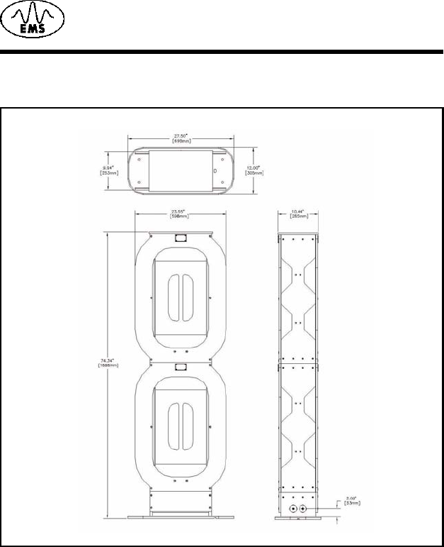
2.1 Dimensions
Figure 2-1. gives the dimensions for the LRP2000 controller.
Installation and Guidelines
4LRP2000 Long Range Passive Reader/Writer
Figure 2-2. gives the dimensions for the LRP2000 antenna.
2.2 Instalation
Antenna Environment
Electromagnetic radiation and the presence of metal within the
reading field of the antenna affect the range of the LRP2000. Mount
the antenna to minimize the impact of these factors.
Installing the Antenna
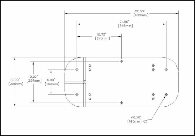
Once a suitable location is selected for the LRP2000 antenna, the
structure should be securely bolted to the floor using the holes
provided in the base. The dimensions for the antenna bolt pattern are
shown in Figure 2.3.
Installation and Guidelines
LRP2000 Long Range Passive Reader/Writer 5
Figure 2-3. Antenna Bolt Pattern
Installation and Guidelines
6LRP2000 Long Range Passive Reader/Writer
LRP2000 Long Range Passive Reader/Writer 7
3
Title
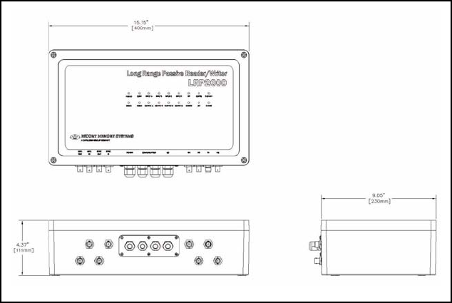
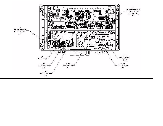
3.1 Connectors and Wiring
Figure 3-1. RF Connectors and Strain Reliefs
Figure 3.1 shows the front connector panel with the four strain reliefs
and the RF connectors. The controller ships with sealing caplugs in
the strain reliefs, which should be left in any unused location for an
environmental seal.
The four strain reliefs will seal around cables ranging in diameter from
0.12 [3.0 mm] minimum to 0.32 [8.0mm] maximum. The wrench flats
are [17mm].
Title
8LRP2000 Long Range Passive Reader/Writer
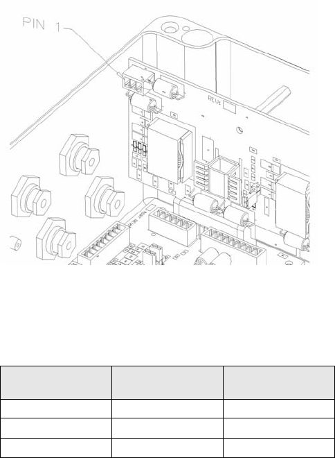
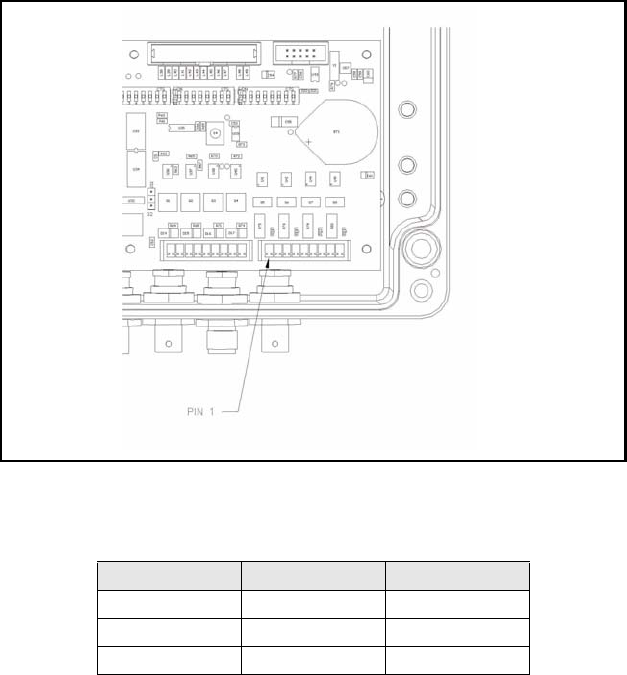
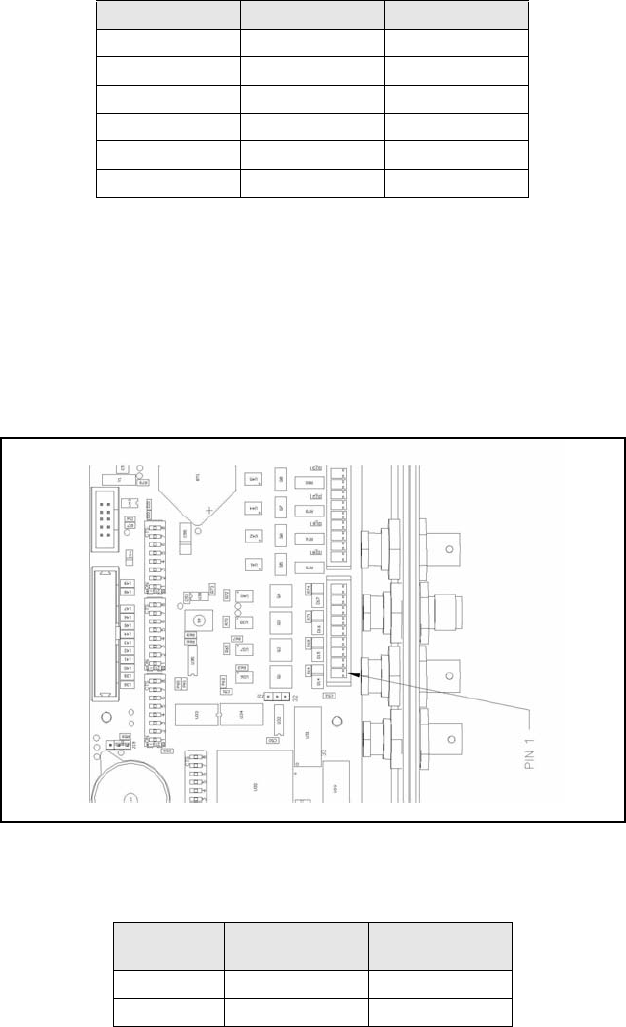
Figure 3-2. Internal Connectors
Figure 3.2 shows an internal view of the controller. It details the
locations of all internal terminal blocks needed for wiring the system.
CAUTION:The controller contains ESD sensitive components.
Always observe ESD-sensitive handling procedures when
working inside the controller.
Terminal Blocks
The controller is equipped with removable terminal blocks to aid
wiring. The data terminals are all equipped with screw terminals which
accept AWG 28 minimum to AWG 16 maximum diameter solid or
stranded wire. The screws heads accept a 3/32 inch [2.0mm] or
[2.5mm] screwdriver blade.
Title
LRP2000 Long Range Passive Reader/Writer 9
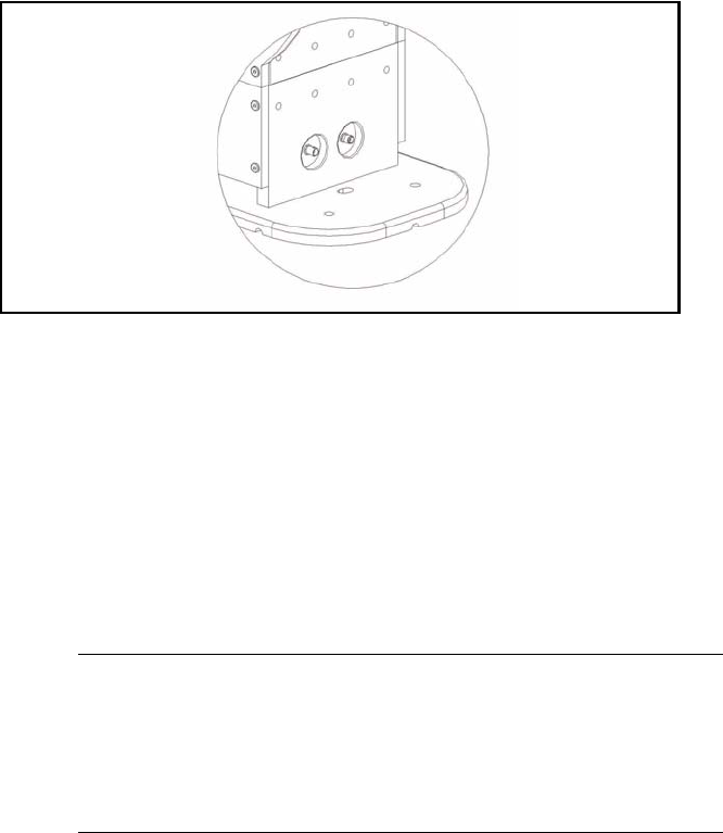
3.2 Antenna Cabling
Figure 3-3. Antenna Connectors
Figure 3.3 shows the two antenna connectors at the base of the
LRP2000 antenna. Connect one end of the antenna cable assembly,
CBL-1475, to the antenna connectors at the base of the antenna.
Mate the connectors at the opposite end of the cable assembly to the
corresponding RF connector on the controller as shown in Figure 3.1.
The cable assembly has two different types of RF connectors, one
threaded TNC and one bayonet-syle BNC. The controller has one
TNC and seven BNC connectors. The BNC connector of the antenna
cable assembly must only be connected to the controller connector
shown in Figure 3.1.
CAUTION:The antenna cables must be properly connected to both
the controller and the antenna at any time that power is
applied to the controller. Failure to properly connect the
controller to the antenna can cause damage to the unit.
Connecting the controller to any antenna other than the
LRP2000 Antenna can not only damage the controller, but
can void the operator's authority to operate the LRP2000.
Title
10 LRP2000 Long Range Passive Reader/Writer
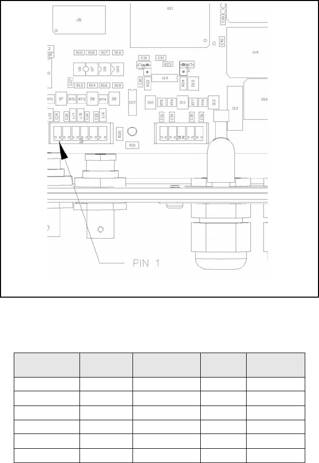
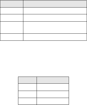
3.3 Data Terminal Blocks
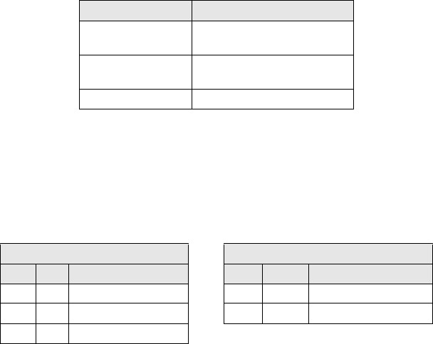
Figure 3-4. J8 COM1 RS232 / COM2 RS232
Figure 3.4 shows the LRP2000 RS232 terminal block, J8, and a detail
view illustrating the arrangement of the terminals.
J
8 Terminal
Number Interface J8 Signal Name DB9 Pin
Number
DB25 Pin
Number
1COM1 RS232 RX 3 2
2COM1 RS232 TX 2 3
3COM1 RS232GND 5 7
4 COM2 RS232 RX 3 2
5COM2 RS232 TX 2 3
6COM2 RS232 GND 5 7
Title
LRP2000 Long Range Passive Reader/Writer 11
NOTE: The signal names given in Table 3.1 refer to the signals from
the LRP2000, not from the host. The DB9 and DB25 pin
numbers are provided for reference. These give the pin
numbers from standard RS232 connectors to which the
LRP2000 terminals should be connected.
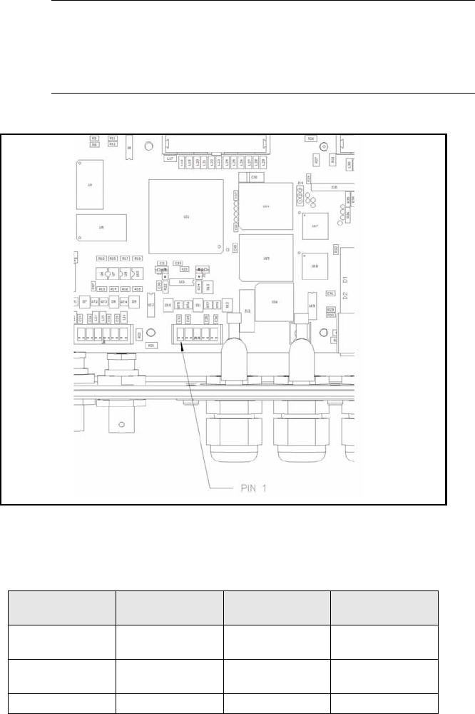
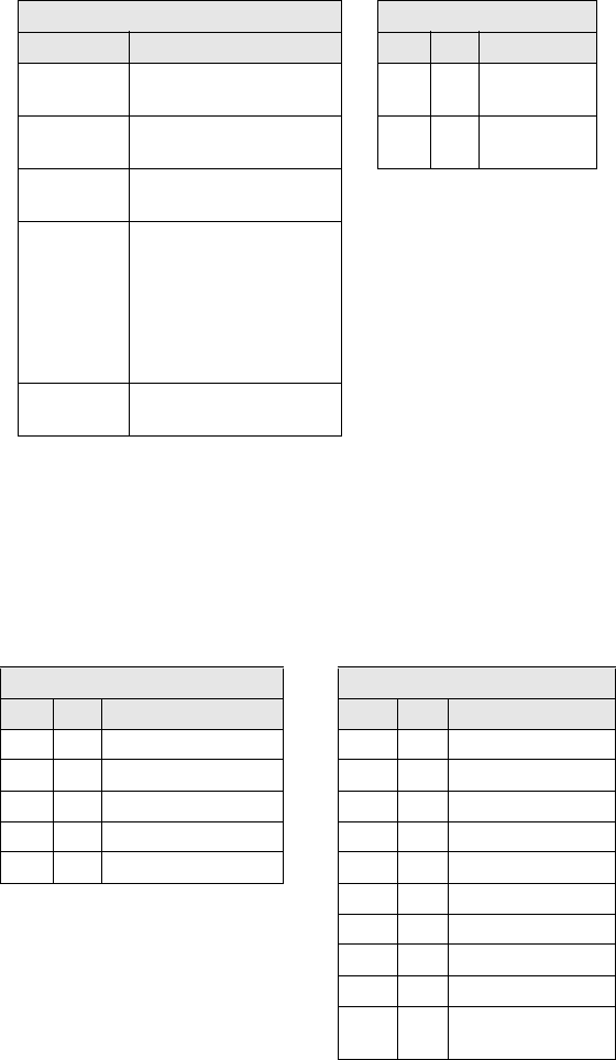
Figure 3-5. J10 COM1 RS422
Figure 3.5 shows the LRP2000 COM1 RS422 terminal block, J10, and
a detail view illustrating the arrangement of the terminals
Table 3-1: J 10 Pinout
J10 terminal
number Signal name Polarity Description
1TX Z - Negative Transmits data to
host
2TX Y + Positive Transmits data to
host
3GND Neutral Auxiliary Ground
Title
12 LRP2000 Long Range Passive Reader/Writer
The signal names given in Table 3.2 refer to the signals from the
LRP2000, not to the signals from the host.
4RX B - Negative Receives data from
host
5RX A + Positive Receives data from
host
Table 3-1: J 10 Pinout
J10 terminal
number Signal name Polarity Description
Title
LRP2000 Long Range Passive Reader/Writer 13
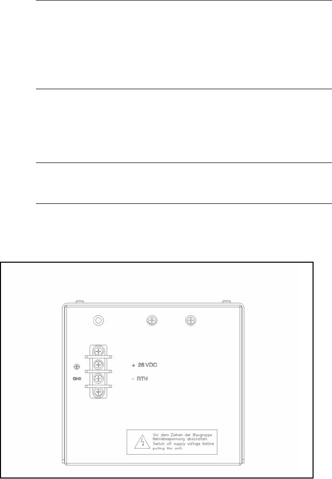
3.4 Power Supply Wiring
CAUTION:The antenna cables must be properly connected to both
the controller and the antenna at any time that power is
applied to the controller. Failure to properly connect the
controller to the antenna can cause damage to the unit.
Connecting the controller to any antenna other than the
LRP2000 Antenna can not only damage the controller, but
can void the operator's authority to operate the LRP2000.
Back out the terminal screws on the terminal block of the power
supply and connect the spade lugs of Cable CBL-1474 to the
terminals according to Table 3.3. Strip 1/4 inch from the opposite ends
of the cable assembly and connect to the input power terminals
according to Table 3.3.
CAUTION:Only after all internal connections are completed should
the LRP2000 Power Supply be connected to the AC
mains.
Figure 3-6. Input Power Supply Lugs
Figure 3.6 Shows the LRP2000 Power Supply and spade lugs.
Title
14 LRP2000 Long Range Passive Reader/Writer
Figure 3-7. Input Power Terminals
Figure 3.7 shows the LRP2000 Input Power Terminals
Table 3-2: Imput Power Pinout
Power Supply Lug Wire color LRP2000 Terminal
Number
+26 RED 3
- RTN BLACK 2
GND Tin 1

Title
LRP2000 Long Range Passive Reader/Writer 15
3.5 RS232 Wiring
The recommended cable medium for RS232 communication is
Belden part number 9941. Specifications for Belden cables can be
found at WWW.BELDEN.COM.
3.6 RS422 Wiring and Termination
In installations where long cable runs must be used, or in noisy
environments, RS422 is them communications standard of choice for
point-to-point serial communications. The recommended cable
medium is Belden p/n 3084A (dropline), or Belden p/n 3082A
(trunkline.) With a maximum baud rate of 38.4 kBaud it is generally
unnecessary to terminate the RS422 terminals to match the
impedance of the cable. The input impedance of the RS422 terminals
is ??? Ohms. This provides an functional impedance match at all baud
rates up 38.4 kBaud, the maximum rate supported by the LRP2000.
NOTE: The RS422 receiver within the LRP2000 controller has
failsafeprotection circuitry which eliminates the need for
any pullup or pulldown resistors on the RS422 lines.
Title
16 LRP2000 Long Range Passive Reader/Writer
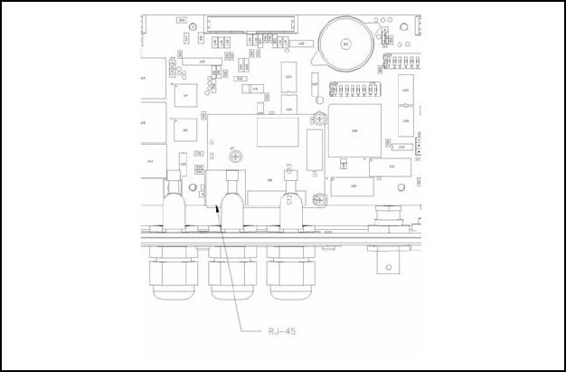
3.7 Ethernet Wiring
Figure 3-8. : The RJ45 Connector on the Optional Ethernet Mod-
ule
.
Because of the narrow size of the strain reliefs on the LRP2000, the
standard RJ-45 connector cannot be inserted through the strain relief.
It is recommended to loosen the nut on the strain relief, feed through
the cable, and crimp the connector in place. After the connector is
crimped onto the cable, the cable can be connected to the Ethernet
module and the excess cable withdrawn from the unit before
tightening the strain relief. Escort Memory Systems recommends
stranded cable for Ethernet wiring in areas where the unit will be
subjected to vibration.
Title
LRP2000 Long Range Passive Reader/Writer 17
3.8 Digital I/O Circuitry
Both the Digital Inputs and Digital Outputs are optically isolated
circuits with no common path between any channel terminal and
another channel, or between any channel and the LRP2000 power.
Because they are independent and floating, the external wiring
controls their use. The inputs can be configured for sensors with a
PNP or NPN output. The outputs can be configured in a Sourcing or
Sinking configuration. The examples in Figures 3.11 through 3.18
show different connections for common input and output devices.
Inputs
The +IN terminal must be at a higher positive potential than the -IN
terminal for current to be sensed correctly. The voltage range is 4.5 to
30V between the +IN and the -IN inputs and the maximum current is
25 mA.
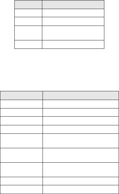
Figure 3-9. J23 Input Connector
Table 3-3: Input Connector Pinout
Terminal number Signal Name Polarity
1+ IN A Positive
2- IN A Negative
3+ IN B Positive
Title
18 LRP2000 Long Range Passive Reader/Writer
Outputs
The output is limited to 30Vdc when off and 500 mA. These are
maximum ratings. A device that operates at 200 mA may destroy the
output due to inrush current if that current exceeds 500 mA(e.g. an
incandescent light). The inductive "kick" (back EMF from a collapsing
magnetic field) when a relay is released can impose a voltage higher
than 30V and destroy the output transistor (use a backwards diode to
clamp the back EMF).
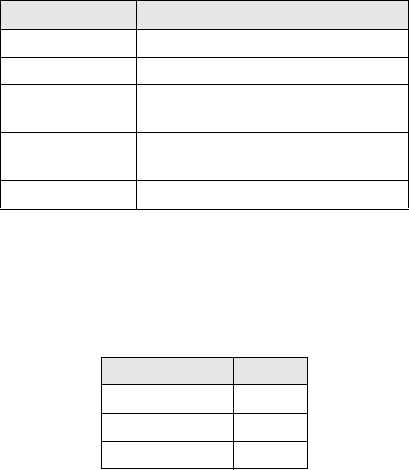
Figure 3-10. J20 Output Connector
4-IN B Negative
5+ IN C Positive
6- IN C Negative
7+ IN D Positive
8- IN D Negative
9GND Neutral
Table 3-4: Output Connector Pinout
Terminal
number Signal name Polarity
1+ OUT A Positive
2- OUT A Negative
Table 3-3: Input Connector Pinout
Terminal number Signal Name Polarity
Title
LRP2000 Long Range Passive Reader/Writer 19
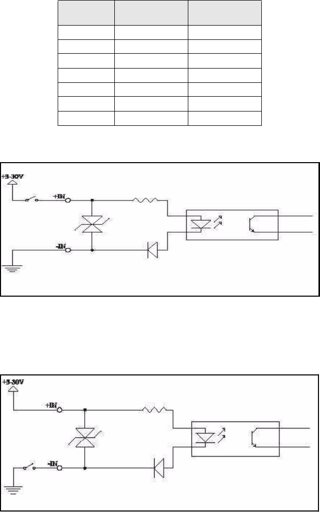
Figure 3-11. Input From Sourcing Contact
Figure 3.11 shows the switch on the high side with the low side
grounded. As this is a "Dry" contact (the current is limited to 15 mA) a
high quality sealed switch should be used.
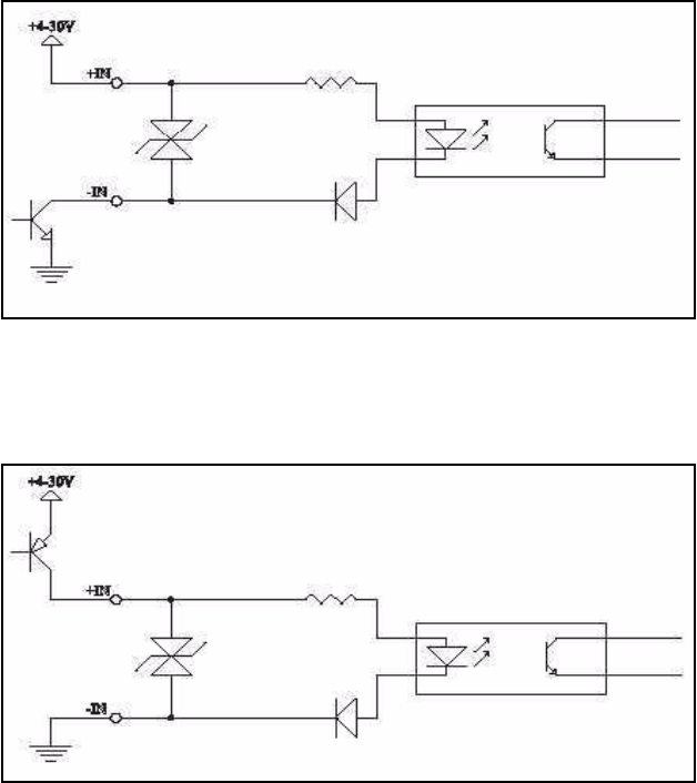
Figure 3-12. Input From Sinking Contact
3+ OUT B Positive
4- OUT B Negative
5+ OUT C Positive
6- OUT C Negative
7+ OUT D Positive
8- OUT D Negative
9GND Neutral
Table 3-4: Output Connector Pinout
Terminal
number Signal name Polarity
Title
20 LRP2000 Long Range Passive Reader/Writer
Figure 3.12 (previous page) shows a switch connected on the low side
with the high side connected to the positive supply. This also requires
a high quality sealed contact.
Figure 3-13. Input From NPN Sensor
Figure 3.13 shows an Open Collector NPN output from a photosensor
switching to ground. It can be wired as a sinking or low-side contact
.
Figure 3-14. Input From NPN Sensor
Figure 3.14 shows an Open Collector PNP output from a photosensor
switches to the positive supply. It can be wired as a sourcing or high-
side contact.
Title
LRP2000 Long Range Passive Reader/Writer 21
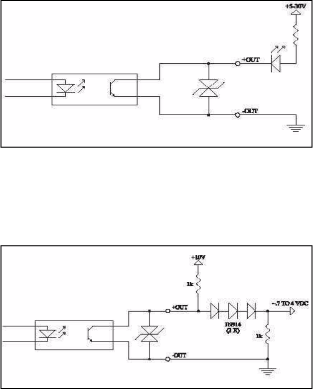
Figure 3-15. Sourcing Output 'Contact'
Figure 3.15 shows a relay connected as a current sourcing "Contact."
The relay is grounded and the +OUT terminal goes to the positive
supply. The diode across the relay coil is essential to protect the
output circuit and reduce noise along the wiring. It should be
connected at the relay to minimize the length of wiring that could
radiate noise. A 1N4001 or similar diode may be used.
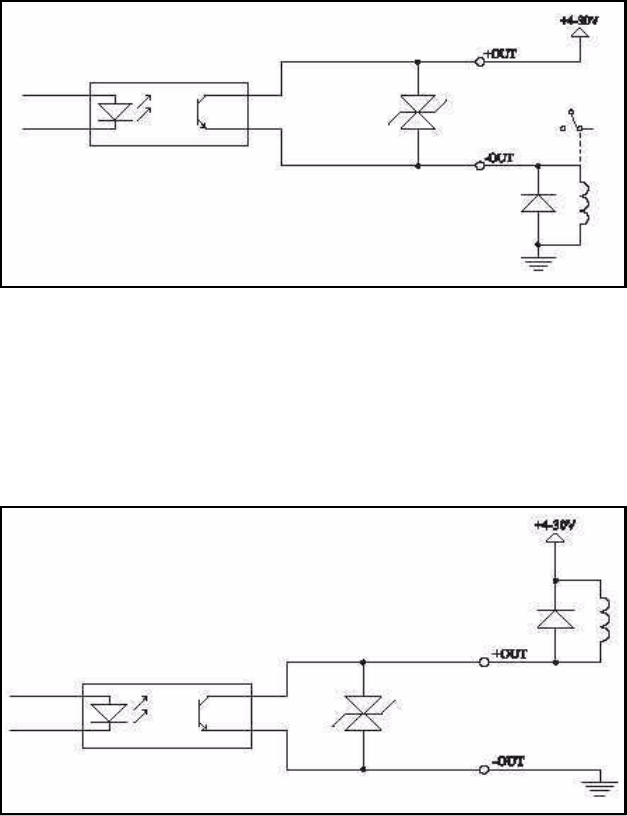
Figure 3-16. Sinking Output 'Contact'
Figure 3.16 shows a "Contact" sinking current from a relay, the -OUT
terminal is grounded and the relay goes to the positive supply. This
configuration must also have a diode across the relay coil to protect
the circuit and reduce noise.
Title
22 LRP2000 Long Range Passive Reader/Writer
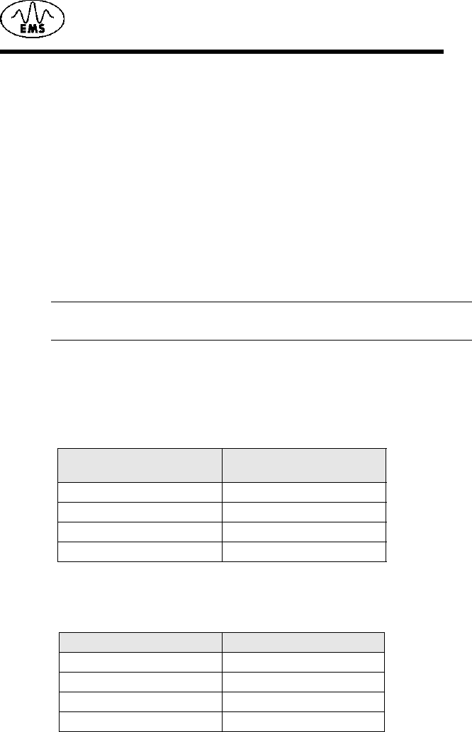
Figure 3-17. Sinking Output LED Driver
In Figure 3.17, the LED and current limiting resistor are in series
between the positive supply and the +OUT terminal. The -OUT
terminal is grounded. The resistor in series with the LED sets the
forward current. 1.2K will provide 20 mA LED current when run from
24 Vdc.
Figure 3-18. Output to TTL or CMOS Logic
In Figure 3.18 the output acts as an Open Collector. This will provide a
TTL or CMOS compatible signal when a 1K to 10K pull-up to +5 Vdc
(the logic supply) is used.
LRP2000 Long Range Passive Reader/Writer 23
4
Communications Interface
4.1 Configuring the Serial Interface
COM1
In normal use for reading and writing RFID tags, communications with
the LRP2000 will be accomplished via the main communications
interface, COM1. This communications interface can be accessed by
both point-to-point and addressed serial communications protocols.
For point-to-point serial communication, the LRP2000 supports
RS232 and RS422 as the standard protocols. For multiplexed
communications, Ethernet is available as an option. Both RS232 and
RS422 interfaces are optically isolated. The RS422 interface is
especially suited for long cable lengths, and for noisy environments.
NOTE: NOTE: The delay between the characters sent to the
controller cannot be longer than 200 ms.
The options for each configuration parameter for the COM1 interface
follow:
The default configuration parameters for COM1 are:
Table 4-2:
Baud rate 9600 bps
Number of Data Bits 8
Number of Stop Bits 1
Parity None
Handshake None
Table 4-1:
Baud rate 1200, 2400, 4800, 9600,
19200, 38400 bps
Number of Data Bits 7, 8
Number of Stop Bits 1
Parity Even, Odd, None
Handshake None, Xon/Xoff

Communications Interface
24 LRP2000 Long Range Passive Reader/Writer
COM2
For the purpose of configuring the controller's operating parameters,
communication will be accomplished via the auxiliary communications
interface, COM2. This auxiliary interface only communicates via
RS232 and is reserved for configuring and updating the operating
parameters and for updating the firmware in the controller. For
example, with the correct hardware dip switch settings, the COM2
interface can be used to configure the parameters of the COM1
interface. The electronics of this interface are also optically isolated
from the other circuits of the controller.
The communication options for the COM2 interface follow:
Table 4-3:
Baud rate 1200, 2400, 4800, 9600,
19200 bps
Number of Data Bits 7, 8
Parity Even, Odd, None
Handshake None, Xon/Xoff
The default configuration parameters for COM2 are:
Table 4-4:
Baud rate 9600 bps
Number of Data Bits 8
Number of Stop Bits 1
Parity None
Handshake None
Digital Board DIP Switch
The digital board is mounted inside the LRP2000 enclosure closest to
the wall with the cable entries. The first 5 switches of the main board
set the COM1 baud rate, electrical interface, and the download
options for COM2. SW6, SW7 and SW8 are not used and should
remain OFF. When switch 1 and 2 are both set ON, the baud rate is
set via the Configuration Menu. The table below illustrates possible
combinations of switch settings for typical applications.
Communications Interface
LRP2000 Long Range Passive Reader/Writer 25
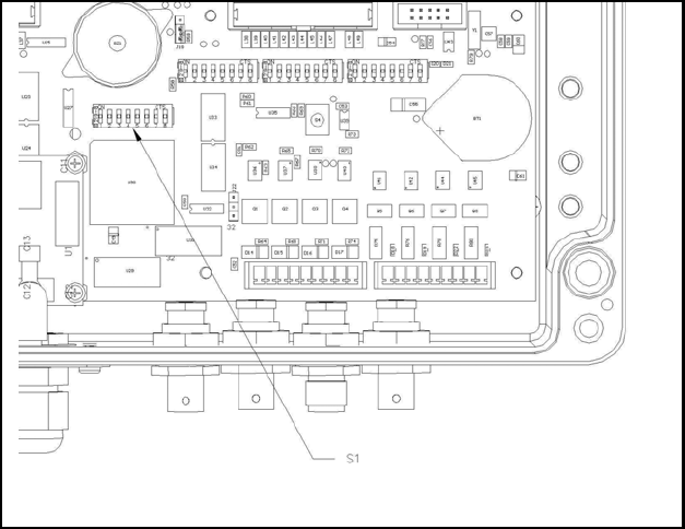
Figure 4-1. Configuration Dip Switch, S1
Figure showing the location of the digital board dip switches, and hard
reset switch. Also includes a detail view of the dip switch array which
indicates the arrangement of the switches from left to right and which
indicates the "ON" and "OFF" directions.
Table 4-5: Dip Switch Settings
Baud Rate Interface
Download/
Restore
Defaults
SW1 SW2 SW3 SW4 SW5 Settings
OFF OFF * *OFF 9600 BAUD
ON OFF * *OFF 19200
OFF ON **OFF 38400
ON ON ** OFF 38400
* *OFF OFF OFF RS232
* * ON OFF OFF RS422
IGNORED IGNORED IGNORED ON OFF Ethernet
IGNORED IGNORED ON ON OFF Reserved
OFF OFF OFF OFF OFF Disabled
IGNORED IGNORED IGNORED IGNORED ON Download /
Restore
Defaults
Communications Interface
26 LRP2000 Long Range Passive Reader/Writer
NOTE: By setting SW5 ON to enable download, the default
parameters will first be restored and saved to the non-volatile
memory, erasing the previously stored communication and
operating parameters. These parameters will take effect after
a hard reset or a power-on reset. A hard reset is invoked by
depressing the hard reset switch, holding for one second,
and releasing. The hard reset switch is shown in Figure 4.1.
The baud rate, as determined by SW1 and SW2, only applies to the
COM1 serial interface. When the optional ethernet interface is
selected by setting switch 4 to the "on" position, the baud rate is set
automatically for Ethernet communication, and switches 1 and 2 are
ignored.
The communication parameters for COM2 can only be changed by
menu configuration. Because COM2 is an auxiliary interface, the
default parameters for COM2 are sufficient for the infrequent use of
this interface, and should not be changed. For example, if a user
changes to a faster baud rate on COM2, a problem can occur when
trying to re-establish communication at a later date. Because there is
no obvious indication that the baud rate has been changed, the next
operator would likely try to reconnect at the default, 9600 baud, and

Communications Interface
LRP2000 Long Range Passive Reader/Writer 27
would be unable to connect. The quickest way to re-establish
communication is to set SW5 ON and reset, then set SW5 OFF and
reset again. This will overwrite all the communication parameters on
COM2 and allow the operator to connect, but it will also overwrite all
the information for COM1, as well as the RFID parameters. The best
practice is always to use the defaults for COM2.
4.2 Optional Ethernet Interface
As an alternative to the RS232 and RS422 interfaces, COM1 of
theLRP2000 can be configured to communicate on Ethernet
networks. Thisoption can be fulfilled by Escort Memory Systems'
Ethernet module. To configure the LRP2000 COM1 to communicate
via Ethernet, set Switch 4 ON. This correctly sets all communication
parameters between the Ethernet module and the controller. Section
4.3 details the configuration of the Ethernet module for network
4.3 Configuring the Ethernet Module for
Network Communication
Once wired correctly, the Ethernet Module must be configured to
communicate on a network of computers and peripherals. This can be
accomplished by connecting the controller's RJ45 jack directly to the
NIC on a PC through a crossover cable. Alternatively, the Ethernet
module can be connected directly to a router of a LAN. This can cause
serious problems if another device on the network has the same IP
address.
The default IP address.
The default IP address of all LRP2000 controllers is set to
192.168.253.222 at the factory. In order to avoid IP address conflicts,
the unit must be assigned a unique IP address before it is installed for
operation. For configuration, the Ethernet module provides an
interactive web page to update addresses.
NOTE: If connecting directly from the NIC on a PC, under some
operating systems with dynamic IP allocation, it is necessary
to fix the IP address of the PC to ensure that the IP address
will not change during configuration.
Communications Interface
28 LRP2000 Long Range Passive Reader/Writer
Once connected, apply power to the LRP2000 and direct the PC's
web browser to http://192.168.253.222. The page shown in Figure 4.2
will be displayed as it is decompressed by the Ethernet module.
Figure 4-2.
Communications Interface
LRP2000 Long Range Passive Reader/Writer 29
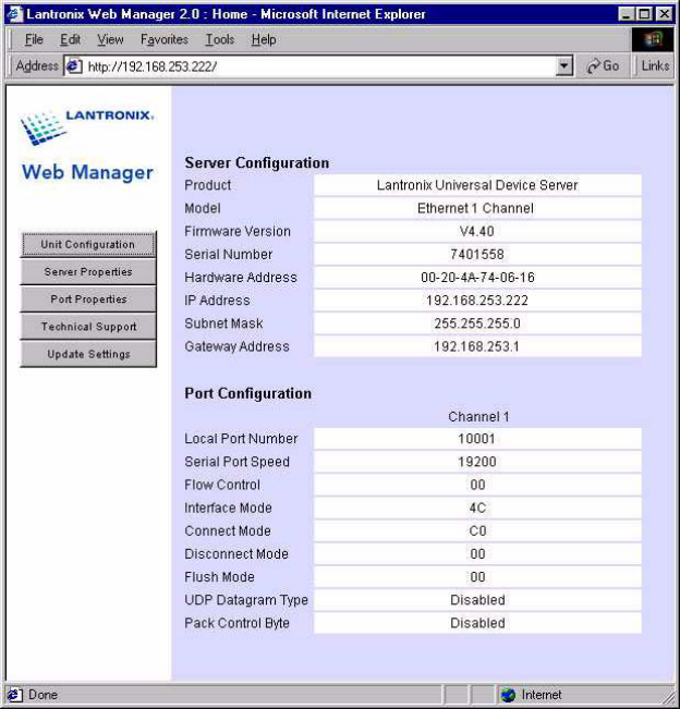
Click "Connect" to see the current configuration of the module as
shown in Figure 4.3.
Figure 4-3.
Communications Interface
30 LRP2000 Long Range Passive Reader/Writer
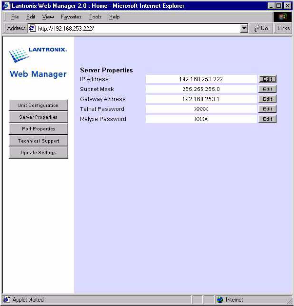
To change the IP address, click "Server Properties" from the menu on
the left side. This will load the Server Properties page as shown in
Figure 4.4.
Figure 4-4.
Click the "Edit" button next to the IP address field to produce a
separate window. Type or paste in the desired IP address and hit
"Enter." Follow the same procedure to change the Subnet Mask and
the Gateway Address. This will only save the information for the
display. After all of the desired parameters are entered correctly, click
"Update Settings" from the menu on the left. This will download the
configuration parameters to the Ethernet Module.

Communications Interface
LRP2000 Long Range Passive Reader/Writer 31
After these steps are completed, reset the LRP2000, and the Ethernet
module will be ready for network communication directed to its new IP
address.
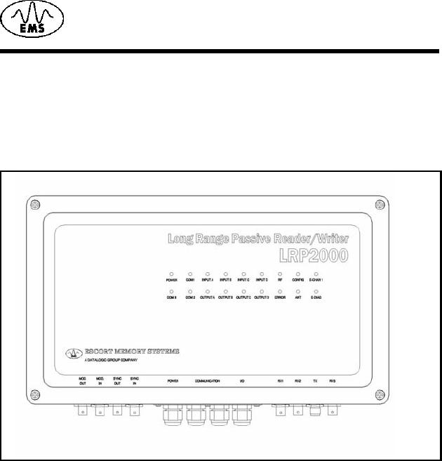
4.4 LED Indicators
The LRP2000 has 18 LED indicators conveniently located on the front
panel to indicate the operating status of the controller. The locations of
the LED indicators is shown in Figure 4.5.
Figure 4-5. LED Indicators
TONY I NEED THIS GRAPHIC
Table 4-6: LED Indicators
LED Color Meaning
POWER RED The LRP2000 is receiving power
COM1 GREEN / RED RED: Incoming data on COM1
RS232 RX
GREEN: Outgoing data on COM1
RS232 TX And COM1 RS422 Y and Z
INPUT A YELLOW The Input is active
INPUT B YELLOW The Input is active
INPUT C YELLOW The Input is active
INPUT D YELLOW The Input is active
RF GREEN RF data transfer
CONFIG GREEN Flashes green for 0.5 seconds to
indicate thesuccessful execution of an
ABx command.
E-CHAN 1 lights solid to indicate that Ethernet
connection is idle, blinks to indicate
that Ethernet Module is connected
and active
COM3 Not Used
COM2 GREEN / RED RED: Incoming data on COM2
RS232 RX
GREEN: Outgoing data on COM2
RS232 TX
OUTPUT A GREEN Output A active
OUTPUT B GREEN Output B active
OUTPUT C GREEN Output C active
OUTPUT D GREEN Output D active

Communications Interface
32 LRP2000 Long Range Passive Reader/Writer
Flashing LED Signals
Flashing LED indicators, or combinations of flashing LED indicators,
are used to indicate certain controller states, or transitions from one
state to another.
ERROR LED - 4 Flashes
The ERROR LED alone will flash four times to indicate that the
controller is entering the download routine. This indicates that Switch
5 is in the ON position during a power-on or hard reset. With a
terminal correctly configured and connected to COM2, the download
menu will be displayed.
ERROR and CONFIG LEDs - 4 Simultaneous
Flashes
The ERROR and CONFIG LEDs will flash simultaneously four times
to indicate that (CTRL-D) has been received within the first seven
seconds of power-on or hard reset. With a terminal correctly
configured and connected to COM2, the configuration menu will be
displayed.
ERROR and CONFIG LEDs - 4 Alternating Flashes
The ERROR and CONFIG LEDs will alternately flash four times to
indicate that the controller is entering operating mode and is ready to
receive commands on COM1.
ERROR RED Flashes red for 0.5 seconds to
indicate the unsuccessful execution of
an ABx command.
ANT RED Antenna is transmitting
E-DIAG Blinks in combination with E-CHAN 1
LED to provide diagnostic information.
See explanation below.
Table 4-6: LED Indicators
LED Color Meaning

Communications Interface
LRP2000 Long Range Passive Reader/Writer 33
E-DIAG and E-CHAN 1 Ethernet Module diagnostic
codes
The E-DIAG LED will light solidly to indicate the following errors.
These errors can be identified by the number of times that the E-
CHAN 1 LED blinks.
Number of
blinks Error
1EPROM
Checksum Error
2RAM Eror
3Network Controller
Error
4EEPROM
Checksum Error
5Duplicate IP
Address on
network
6Software does not
match hardware
The E-DIAG LED and the E-CHAN 1 LEDs will blink at the same time
to indicate the following errors:
Number of
blinks Error
4 Faulty Network
Connection
5 No DHCP Response
Received
Communications Interface
34 LRP2000 Long Range Passive Reader/Writer
LRP2000 Long Range Passive Reader/Writer 35
5
Configuring the Menu
5.1 How to Enter Menu Configuration
Begin by connecting the COM2 port to your PC host and running EC
that is available on the diskette or from Escort Memory Systems Web
site at www.ems-rfid.com. Set the serial parameters to the LRP2000
default settings or the last known state of COM2. The default settings
for COM2 are as follows:
Table 5-1:
Baud 9600
Parity None
Data bits 8
Stop bits 1
Flow control None
If you can not establish communications with COM2, do the following
to restore the default values.
1. 1. Place DIP switch five in the ON position and cycle power to the
LRP2000 or press the reset switch. This will load the default
values.
2. 2. Place DIP switch 5 in the OFF position and cycle power once
more.
Please refer to Chapter 4, Serial and Bus Communications, for more
information on the serial interface. To enter the Main Board
configuration menu, cycle power or press the reset switch, and
thenpress CTRL-D within the first seven seconds of the initialization.
The LRP2000 will enter the Configuration Menu. As the LRP2000
starts the Configuration program, both the RF and CONFIG LEDs will
flash. The Main Board Configuration menu will display with the
current main board software version number together with the DSP
firmware version.
*******************************************
LRP2000 (ISO Only) Standard Program
Main Program V0.5D, Sept 2002
Configuring the Menu
36 LRP2000 Long Range Passive Reader/Writer
DSP Program V0.5c, November 2002
*******************************************
[1] Set-up Operating Parameters
[2] Download Main Program
[3] Download DSP Program
[4] Exit to Operating Mode
Enter Selection:
5.2 Set-up Operating Parameters
To change the operating parameters of the LRP2000, enter 1 at the
initial menu. The following menu will be displayed, listing the current
settings. The exact appearance of the menu display will dependon the
settings you have made, and will be updated when you save your
changes.
Serial Port COM1: RS232, 9600, N, 8, 1, No handshake
(DIP switches)
Serial Port COM2: RS232, 9600, N, 8, 1, No handshake
Operating Mode: ABx Standard
RF Communication: Fast Mode
[1] Set COM1 Parameters
[2] Set COM2 Parameters
[3] Set Operating Mode
[4] Set RF Communications
[5] Restore Factory Defaults
[6] Return to Main Menu
Enter Selection: Enter the number of the sub-menu you wish to enter.
When you have made your selection you will be prompted to save
your changes to the non-volatile EEPROM. For the new settings to
take effect, you must save your changes to the EEPROM and reset
the LRP2000. If you do not save changes to the EEPROM, the new
settings will be effective only until the LRP2000 is reset. The following
sub-menus are presented here in their entirety. When operating, the
menus will be presented one option at time, advancing as you enter
selections. Some options shown are dependent on earlier selections.
Configuring the Menu
LRP2000 Long Range Passive Reader/Writer 37
Set COM1 Parameters
Selecting 1 from the above menu will present the following display for
the COM1 parameters. These settings are valid only if you are not
using the DeviceNet Interfaces (e.g. DIP switch 4 is in the OFF
position). Enter the appropriate number at each prompt. The default
values are indicated by an asterisk (*).
*** Set COM1 Parameters ***
Baud Rate? [0] 1200 [1] 2400 [2] 4800 [3] 9600* [4]
19200 [5] 38400
Data size? [0] 7 bit [1] 8 bit*
Parity? [0] None* [1] Even [2] Odd
Handshake? [0] None* [1] Xon/Xoff
Save Changes to EEPROM? [0] No [1] Yes
Selecting 2 from the "[1] Set-up Operating Parameters" menu will
bring up the following display for the COM2 parameters. Enter the
appropriate number at each prompt. The default values are indicated
by an asterisk.
*** Set COM2 Parameters ***
Baud Rate? [0] 1200 [1] 2400 [2] 4800 [3] 9600* [4]
19200
Data size? [0] 7 bit [1] 8 bit*
Parity? [0] None* [1] Even [2] Odd
Handshake? [0] None* [1] Xon/Xoff
Save Changes to EEPROM? [0] No [1] Yes
Set Operating Mode
The "[3] Set Operating Mode" menu allows you to choose the ABx
command protocol the LRP2000 will use, or configure it to
automatically enter Continuous Read Mode upon start-up.
*** Set Operating Mode ***
Command Protocol? [0] ABx Standard* [1] ABx Fast [2]
ABx ASCII
Checksum? [0] Disabled* [1] Enabled
Power up in Continuous Read Mode? [0] NO [1] Single
Configuring the Menu
38 LRP2000 Long Range Passive Reader/Writer
Tag [2] Multiple Tag
Start Address (0 to 47)
Length (1 to 48)
Delay Between Duplicate Decodes (0 to 60)
Raw Read Response? [0] NO [1] CR terminate [2] CR/LF
terminate
Save Changes to EEPROM? [0] No [1] Yes
Command Protocol?
The LRP2000 offers three modes for the transfer of data and
commands. ABxStandard (ABxS) uses only the LSB for tag data while
ABx Fast (ABxF) will use both the MSB and the LSB for the passing of
data. ABx ASCII (ABxA)mode permits RFID operations using seven
bit data packets in the form of printable ASCII characters.
Checksum
ABx Fast and ABx ASCII also permits you to include a checksum in
the command. To use a checksum value with the ABx commands, you
must enable the checksum option. It is recommended that you enable
the checksum option.
Power up in Continuous Read Mode
You also have the option of setting the LRP2000 to start-up in
Continuous Read Mode. When you have configured the LRP2000 to
function in this manner,you do not issue commands to the LRP2000. It
will, upon start-up, enter directly into a Continuous Read Mode. Since
this bypasses the normal command parameters, you must specify the
Continuous Read Mode parameters. The LRP2000 will respond to
other commands and resume Continuous Read Mode when
completed. If you are using your LRP2000 in this mode, you must
choose if you want the LRP2000 to read a single tag or read multiple
tags within the field. To exit Continuous Read Mode you must either
re-enter the configuration menu and select NO from the Power up in
Continuous Read Mode option, or issue a Continuous Read command
from the host with a read length of 0 as described in Chapter 6, RFID
Interface.
Start Address (0 to 111)
Enter the tag address where you want the read to begin.
Length (1 to 112) 112
Enter the length of the read you wish the LRP2000 to perform. Make
certain that the length value does not exceed the number of possible
addresses following the starting tag address. Entering a read length of
0 will disable Continuous Read Mode.
Configuring the Menu
LRP2000 Long Range Passive Reader/Writer 39
Delay Between Identical Decodes (0-60)
The Delay Between Identical Decodes parameters can have a value
of 0 to 60 seconds. When the Delay Between Identical Decodes is set
to 0, the LRP2000 will continuously read AND transmit tag data to the
host. This can flood the buffers and cause communication errors and
data loss.
Raw Read Response
If you have selected ABx Fast or ABx ASCII, you have the option of
stripping the command protocol from the data and adding a terminator
to separate the data packets. You can choose a CR (0DH) or CR/LF
(0DH, 0AH) to terminate the data.
Set RF Communication
The LRP2000 should be configured with the default (0) Fast Mode.
*** Set RF Communication ***
RF Communication? [0] Fast Mode* [1] Standard Mode 0
Save Changes to EEPROM? [0] No [1] Yes
Restore Factory Defaults
It is often helpful during troubleshooting to restore the LRP2000 to
known default values. To do so, select 5 from the "[1] Set-up
Operating Parameters" menu .
*** Restore Factory Defaults ***
Restore Factory Default? [0] No [1] Yes
The restored defaults will be saved to the EEPROM. The
communication defaults can also be restored by placing the main
board DIP switch number 5 in the ON position and then restarting the
LRP2000. After you have saved any changes, you must re-initialize
the LRP2000 with switch 5 in the OFF position.
Return to Main Menu
When you have completed your configuration, entering 6 will return
you to the initial menu. Unsaved changes will be effective until the
LRP2000 is reset. Saved changes will be loaded automatically the
next time the LRP2000 is reset, or upon selection of "[4] Exit to
Operating Mode" from the main menu.

Configuring the Menu
40 LRP2000 Long Range Passive Reader/Writer
5.3 Download New Program
Before attempting to download new firmware to the LRP2000 main
board,read the instructions provided in a readme.txt file on the update
diskette. When you select 2 from the Main Menu, the LRP2000 will
display information on the current program and prompt you to begin
the download.
*** Download New Program***
Program Size :21824 Bytes
Program Checksum :5AE0H (OK)
Free Program Memory :39600 Bytes
Flash Write Counter :2 times
Press a key to start Downloading
After you have pressed a key, the LRP2000 will display:
Send the Intel Hex file. Downloading now.
Send the new program file via your terminal emulation program in Text
(Hyperterminal: Transfer->Send Text file) or ASCII (EC: PgDn-
>ASCII).
NOTE: It is not necessary to download firmware
into the unit unless instructed to do so
by Escort Memory Systems technical
support personnel.
5.4 Downloading DSP Firmware
Before attempting to download new firmware to the LRP2000 main
board, read the instructions provided in a readme.txt file on the update
diskette. When upgrading software in the controller the number and
meaning of the configuration parameters may not match between the
old and new software. The old settings may not be interpreted
properly with the new software. Before downloading another version
of software, display and record the current configuration settings.
Then download the new software version. Set switch 5 (on the main
board) on and apply power to initialize the configuration parameters to

Configuring the Menu
LRP2000 Long Range Passive Reader/Writer 41
their default states. When the LEDs stop flashing, turn Switch 5 to Off
and press the reset switch. Enter the Configuration Menu and re-enter
any non-default configuration parameters. When you select 3 from the
Main Menu, the LRP2000 will prompt you to begin the download.
*** Download DSP Firmware***
Press a key to start Downloading
After you have pressed a key, the LRP2000 will display:
Send the Intel Hex file. Downloading now.
Send the new firmware via your terminal emulation program in ASCII
text or Hexadecimal format. The firmware will be automatically
transferred to the DSP Flash Memory. Wait 10 seconds after the
download is complete before resetting the LRP2000.
Record: 750
Download OK
File Transfer to DSP
Blocco 24/24
DSP Flash Programming...
New Firmware Transferred to DSP
CAUTION:Do not download a DSP file into the microcontroller.
CAUTION:It is not necessary to download firmware into the unit
unless instructed to do so by Escort Memory Systems
technical support personnel.
42 LRP2000 Long Range Passive Reader/Writer
5.5 Exit to Operating Mode
This option is available if you wish to use temporary, unsaved,
configuration parameters. The unsaved options you have selected will
be used until the LRP2000 is reset and the saved parameters are
restored.

LRP2000 Long Range Passice Reader/Writer 43
6
RFID Interface
6.1 Introduction
Conventions
In this manual, numbers expressed in Hexadecimal are appended
with "H." For example, the number of fingers on a typical person will
be expressed either as "10" in decimal or as "AH" in hexadecimal.
The addresses of the bytes of read/write memory within an RFID tag
are numbered from 0 to N, where N is one less than the number of
read/write bytes in the tag. The number of read/write bytes is equal to
the Block Size multiplied by the Number of Blocks. These parameters
can be found for a particular tag using the ABx Command 16H, Get
Label Information.
Command protocols
The LRP2000 offers three possible command protocols: ABx
Standard, ABx Fast and ABx ASCII. The ABx Standard format is
word-based and shares a common syntax with most existing RFID
systems produced by Escort Memory Systems.The ABx Fast and ABx
ASCII protocols are byte-based packet structures that permit
command execution with fewer total bytes transferred. Escort
Memory Systems offers more support for ABx Fast protocol in terms
of examples and demonstration software. Because of this, and the
fact that ABx Fast speeds communication while increasing error
immunity, operators are encouraged to implement ABx Fast protocol.
The commands in all three protocols consist of the same basic
structure. They comprise a header, a number of parameters, and a
command terminator. The headers and terminators are unique to each
protocol, but are the same for every command within one protocol. For
example, in ABx Standard, every command begins with the one-byte
header "AAH," and ends with the two-byte terminator "FFFFH". In ABx
Fast and in ABx ASCII, every command begins with the 0202H, and
ends with 03H. Like the commands, the responses from the controller
comprise a header, a number of response codes and data, and a
response terminator. The headers and terminators are the same for
the responses as they are for the commands. The ABx command set
is made of three subsets: the single-tag commands, multi-tag
commands, and user I/O commands. The single-tag commands
perform read/write operations on exactly one tag in the range of the
antenna at a time. The presence of more than one tag within the
range of the antenna may cause RFID communication errors. To
avoid these errors, the multi-tag commands allow for simultaneous

RFID Interface
44 LRP820S-Series Long-Range Passive Reader/Writers
communication to and from multiple tags within the reading range of
the antenna. The user I/O commands do not communicate with RFID
tags. They simply interrogate the status of the inputs wired to the unit,
and to the status of the outputs. Table4.1 and 4.2 list the ABx
commands recognized by the LRP2000.
Table 4.1 and 4.2- ABx Command Set Listings
Single tag Commands
04H Fill Tag
05H Block Read
06H Block Write
07H Read Tag Serial Number
08H Tag Search
0DH Continuous Block Read
14H Get Block Status
15H Get Label Information
16H Write Family Code
17H Lock Family Code
Multi tag commands
82H SN Block Read All
83H Start/Stop Continuous SN Block
Read All
84H Fill Tag All
85H Block Read All
86H Block Write All
87H Read Tag SN All
88H Tag Search All
8DH Start/Stop Continuous Read All
8EH Memory Lock All
8BH Write Family Code All
8CH Lock Family Code All
94H SN Fill
95H SN Block Read
96H SN Block Write
User I/O
Commands:
10H
Set Output 11H

RFID Interface
LRP2000 Long Range Passice Reader/Writer 45
NOTE: The delay between the characters of a command sent to the
controller cannot be longer than 200 ms.
6.2 Command Parameters
Command Timeout
All single-tag and multi-tag commands have a timeout value that is
used to specify the time the controller will attempt to complete the
specified operation. The absolute minimum timeout value which can
be issued to the controller is 1 millisecond. The absolute maximum
time for which the controller will attempt to complete a command is
just over one minute. The timeout parameter is passed to the
controller in units of milliseconds with a maximum value of 65,534
(FFFEH) milliseconds. A timeout value of 0 will generate a syntax
error. Thirty milliseconds is the shortest recommended timeout and
should only be used for single tag command applications. Multiple tag
commands will require longer timeout values. For applications where
the time that the tags spend in the field must be short, tests should be
performed to ensure that a sufficiently large timeout value is chosen in
order to read all of the tags. A longer timeout value does not
necessarily mean that a command will take any longer to execute. If
the tags being addressed are in the field, it only represents the period
of time (in milliseconds) the unit will attempt to execute the command.
If the tags are present, the response time to execute the command will
be the same whether the timeout is 100ms or 10,000ms.
Delay Between Duplicate Decodes
The one parameter which is unique to the single-tag command 0DH is
Delay Between Duplicate Decodes. After Continuous Read is started,
any tag that comes within range of the antenna will be read and the
requested data from the tag will be sent to the host. This delay
parameter represents the number of seconds that a tag must remain
out of range before it is read a second time. This delay is implemented
to enable the operator to limit the volume of information sent by the
controller. With this delay parameter set to 00H, the controller will
repeatedly send the requested information until the tag is out of range.
The maximum allowable value is 60(3CH) seconds.
Input Status
82H SN Block Read All
RFID Interface
46 LRP820S-Series Long-Range Passive Reader/Writers
Multi-tag Command Parameters
Tag Repeat Count
This parameter is used on the multi-tag Continuous Read commands,
83H and 8DH. After Continuous Read is initiated, any tag that comes
within range of the antenna will be read and the requested data from
the tag will be sent to the host. The Tag Repeat Count parameter
represents the number of other tags which must be read before the
data from the first tag will be sent for a second time. This count is
implemented to enable the operator to limit the volume of information
sent by the controller. In this way, it is functionally similar to the Delay
parameter used in the single-tag Continuous Read command. The
difference between the two is that the single-tag parameter indicates
an amount of time for which a tag must remain out of range of the
antenna in order for its data to be sent a second time. The Tag Repeat
Count is strictly the number of tags whose data will be sent before the
data from a certain tag is sent again. With this Count parameter set to
00H, the controller will repeatedly send the requested information until
the tags are out of range.
Selectively Reading and Writing Tags By Family
The multi-tag commands always have a Family Code as a parameter.
This parameter manages the reads and writes when multiple tags are
in the reading field. This parameter can be used to differentiate
between tags without communicating directly with all of the tags in the
field at one time. In this condition it is still possible to communicate
with individual tags through the use of commands 94H, 95H, and 96H.
These commands operate on one specific tag by including the tag's
unique serial number as a parameter. The Family Code is a one-byte
field in the tag which resides outside the read/write memory address
space. When the Family Code parameter is set to 0, the command is
broadcast to all the tags in the field. On the other hand, if the Family
Code parameter is set to a non-zero byte value, only tags with
implementing a multi-level organization of the tags, by permitting
thethe specified Family code will respond. This feature can help in
selective reading of tags by Family Code. This gives faster access to
the tags than by using Family Code zero. The Family Code byte can
be read, written, and locked independently of the rest of the read/write
address space in the tag.
Anticollision Index

RFID Interface
LRP2000 Long Range Passice Reader/Writer 47
The multi-tag commands in the ABx protocols include a parameter
which is not used with ISO15693-compliant tags. The Byte allocated
for this obsolete parameter has been left in the multi-tag command
packets. It is referred to as the "Anticollision Index" in documentation
for EMS products with firmware support for LRP-L series tags. This
series of tags does not comply with the ISO-15693 standard. The
Anticollision Index is ignored by the controller and may be set to any
value, but to maintain consistency in the case that this byte is used in
the future, it is recommended to set this Byte to 00H.
Start Continuous Read
This parameter, included only on command 83H, is a one-Byte
parameter which starts the Continuous Read if set to 01H, and stops
the Continuous Read if set to 00H. Both of the other Continuous Read
commands-- 0DH and 8DH rely on the Number of Bytes to be read to
start and stop the command. If the Number of Bytes is set to any valid
nonzero value, the Continuous read starts. If it is set to zero, the
Continuous Read stops. The use of this additional parameter on
command 83H allows for the Number of Bytes to be set to zero upon
initiation of the command, thereby interrogating the tags only for their
serial numbers.
6.3 Standard Abx Protocol
6.3 ABx Standard Protocol
The ABx standard is a binary protocol, word (2-byte) oriented, so
thesyntax table reports the Most Significant Byte (MSB) and the
LeastSignificant Byte (LSB). In the serial transmission, the MSB
istransmitted first.
Field Number
of Bytes Content
Header 1AAH
Command 1 Command Code
Start
Address
2one word gives the first Byte of tag memory
to be accessed
Number of
Bytes
2One word gives the number of contiguous
bytes to be accessed. Not used on 07H,
08H, 14H, 15H, 16H
RFID Interface
48 LRP820S-Series Long-Range Passive Reader/Writers
Block
Addresses
2The first Byte gives the address of the first
block. The second Byte gives the number of
blocks to be interrogated. Only used with
command 14H.
Timeout 20001H to FFFEH milliseconds
Data varies Data which will be written to a tag. Each byte
is included in the LSB of a two-Byte word.
Terminator 1 FFFFH
Field Number of
Bytes Content
Header 1AAH. Always the MSB of the first word of an
ABX Standard command
Command 1Command Code - LSB of the first word
Family code 1LSB 00H to address all tags in field
Reserved 1Reserved for future use, set to 00H
Start Address 2One word gives the first Byte of tag memory to
be accessed
Number of Bytes 2One word gives the number of contiguous
bytes to be accessed - Not used with
commands 87H, 88H, 8EH, 8BH, 8CH
Block Addresses 4 The first word gives the address of the first
block. The second word gives the number of
blocks to be interrogated - Only used with
command 8EH
Timeout 20001H to FFFEH milliseconds
Data varies Data which will be written to a tag. Each byte is
included in the LSB of a two-Byte word.
Terminator 2 FFFFH
Field Number
of Bytes Content

RFID Interface
LRP2000 Long Range Passice Reader/Writer 49
*******************************************************************************
ABxS Command 04H: Fill Tag
DESCRIPTION
Fill an RFID tag with a one byte value over multiple contiguous
addresses.
DISCUSSION
This command is commonly used to clear contiguous segments of a
tag's memory. It writes a one byte value repetitively across a specified
range of tag addresses. The fill function requires one data value byte,
a starting address, and a fill length. It will then proceed to fill the tag
with the data value byte, starting at the specified start address for the
specified number of consecutive bytes. When Fill Length is set to 0,
the controller will write fill data from the start address to the end of the
tag's memory. The timeout value is given in 1 msec increments and
can have a value of 001EH to FFFEH (65,534 ms). When the timeout
is set to 0, the controller will return a syntax error.
Field Remarks
Command Command number in hex
preceded by AAH
Start Address The tag address
where the fill will start
Fill Length The number of tag addresses
to be filled in bytes
Timeout Timeout value given in 1 ms
units (10H - FFFEH)
Data Value Byte The byte to be used as fill
Message Terminator FFFFH

RFID Interface
50 LRP820S-Series Long-Range Passive Reader/Writers
Example
The goal is to write ASCII 'A' (41H) to the ten bytes of tag memory
starting at byte address 5. A timeout of 2 seconds (07D0H = 2000 x 1
msec increments) is set for the completion of the command.
Command from Host SuccessfulResponse From Controller
MSB LSB Remarks AAH 04H Command echo
AAH 04H Perform
Command 4
FFH FFH Message
Terminator
00H 05H Start Address =
0005H
00H 0AH Fill Length= 10
bytes(000AH)
07H D0H Timeout value
00H 41H Data Value Byte =
41H
FFH FFH Message
Te r m i n a t or

RFID Interface
LRP2000 Long Range Passice Reader/Writer 51
****************************************************************************
ABxS Command 5 (05H): Block Read
DESCRIPTION
Read data from contiguous bytes of the RFID tag's read/write
memory.
DISCUSSION
This command is used to read bytes from contiguous areas of tag
memory. The minimum length of the data read from the tag is 1 byte.
The maximum is the entire read/write address space of the tag. The
timeout value is given in 1 msec increments and can have a value of
001EH to FFFEH (65,534 ms). When the timeout is set to 0, the
controller will return a syntax error. The Block Read command
consists of a start address and length, followed by the message
terminator, FFFFH, as shown below. If the read range exceeds the
last tag address, the controller will return error message 21H, invalid
format. The data read from the tag is returned in the less significant
byte of the word, and the more significant byte is always 00H.
Field Remarks
Command Command number in hex
preceded by AAH
Start Address The tag address where the
read will start
Read Length The number of tag addresses
to be read
Timeout Timeout value given in 1 ms
units (001EH - FFFEH)
Message
Terminator
FFFFH
RFID Interface
52 LRP820S-Series Long-Range Passive Reader/Writers
Example
The goal is to read the 8 bytes of data from the tag starting at address
1. A timeout of 2 seconds (07D0H = 2000 x 1 msec increments) is set
for the completion of the Block Read.
Command From Host Response from controller
MSB LSB Remarks MSB LSB Remarks
AAH 05H Perform
Command 5
AAH 05H Command echo
00H 01H Start byte Address
= 0001H
00H 52H Read Data 1
=52H
00H 08H = 8 bytes(0008H) 00H 46H Read Data 2
=46H
07H D0H Timeout Value 00H 49H Read Data 3
=49H
FFH FFH Message
Terminator
00H 44H Read Data 4
=44H
00H 20H Read Data 5
=20H
00H 54H Read Data 6
=54H
00H 61H Read Data 7
=61H
00H 67H Read Data 8
=67H
FFH FFH Message
Terminator

RFID Interface
LRP2000 Long Range Passice Reader/Writer 53
*******************************************************************************
ABxS Command 6 (06H): Block Write
DESCRIPTION
Write a block of data to an RFID tag.
DISCUSSION
This command is used to write segments of data to contiguous areas
of tag memory. It is capable of transferring up to 112 bytes of data
transferred from the Host with one command. The timeout value is
given in 1 msec increments and can have a value of 001EH to FFFEH
(65,534 ms). When the timeout is set to 0, the controller will return a
syntax error. The Block Write command consists of a start address
followed by the data stream to be written to the RFID tag. If the write
range exceeds the last tag address, the controller will return error
message 21H, invalid format. The controller will also return an error if
the write length is 0. The data to be written to the tag is contained in
the LSB of the register, and the MSB is always 00H.
Field Remarks
Command Command number in hex preceded by
AAH
Start Address The tag address where the write will
start
Write Length The number of tag addresses to be
written to in bytes
Timeout Timeout value given in 1 ms units
(001EH - FFFEH)
Write Data The data to be written
Message Terminator FFFFH

RFID Interface
54 LRP820S-Series Long-Range Passive Reader/Writers
Example
Writes 4 bytes of data to the tag starting at address 0020H. A timeout
of 2 seconds (07D0H = 2000 x 1 msec increments) is set for the
completion of the Block Write.
Command from host Response from controller
MSB LSB Remarks MSB LSB Remarks
AAH 06H Perform
Command 6
AAH 06H Command echo
00H 20H Start Address
= 0020H
FFH FFH Message Terminator
00H 04H Write Length =
4 bytes
07H D0H Timeout Value
00H 52H Write Data 1
=52H
00H 46H Write Data 2
=46H
00H 49H Write Data 3
=49H
00H 44H Write Data 4
=44H
FFH FFH Message
Terminator
RFID Interface
LRP2000 Long Range Passice Reader/Writer 55
*******************************************************************************
ABxS Command 7 (07H): Read Tag Serial Number
DESCRIPTION
This command retrieves the eight-byte tag serial number.
DISCUSSION
Each controller tag has a unique serial number. This number cannot
be changed and is not part of the available data bytes. The tag serial
number will be returned in the LSB only, with the MSB as 00H.
Field Remarks
Command Command number in hex
preceded by AAH
Timeout Timeout value given in 1 ms units
(001EH - FFFEH)
Message Terminator FFFFH
Example
This example will wait until a tag is in range and then reads the 8-byte
serial number. In this example the ID is 1E6E3DC200000000H in
hexadecimal.
Command from host Response from controller
MSB LSB Remarks MSB LSB Remarks
AAH 07H Perform
Command 7
AAH 07H Command Echo
07H D0H Timeout 00H 001EH First SN byte
FFH FFH Message
Terminator
00H 6EH Second SN byte
00H 3DH Third SN byte
00H C2H Fourth SN byte
00H 00H Fifth N byte
00H 00H Sixth SN byte
00H 00H Seventh SN byte
00H 00H Eighth SN byte
FFH FFH Message Terminator
RFID Interface
56 LRP820S-Series Long-Range Passive Reader/Writers
*******************************************************************************
ABxS Command 08H: Tag Search
DESCRIPTION
Check to see if there is an RFID tag in the field.
DISCUSSION
This command will activate the controller to search for the presence of
a tag within range of the antenna. If the controller finds a tag it will
return a command echo to the host. The timeout value is given in 1
msec increments and can have a value of 001EH to FFFEH (30 to
65,534 ms). When the timeout is set to 0, the controller will return a
syntax error. If no tag is present, it will return an error message. See
Section 6.2 for more information on error codes.
Field Remarks
Command Command number in hex
preceded by AAH
Timeout Timeout value given in 1 ms
units (001EH - FFFEH)
Message Terminator FFFFH
Example
Checks for an RFID tag in the RF field. A timeout of 2 seconds
(07D0H = 2000 x 1 msec increments) is set for the completion of the
Tag Search.
Command from host Response from controller
MSB LSB Remarks MSB LSB Remarks
AAH 08H Perform Command 8 AAH 08H Command echo
07H D0H Timeout Value FFH FFH Message Terminator
FFH FFH Message Terminator

RFID Interface
LRP2000 Long Range Passice Reader/Writer 57
*******************************************************************************
ABxS Command 0DH: Stop/Start Continuous Block
Read
DESCRIPTION
When in Continuous Block Read mode, the controller sends block
read commands continuously to any tag in range of the antenna.
When a tag comes within range, it is read and the data passed to the
host computer. The controller continues to read the tag but will not
send the same data to the host until the tag has been outside the RF
field for a specified time period. This Delay Between Identical
Decodes parameter prevents redundant data transmissions when the
controller is in Continuous Block Read mode.
DISCUSSION
The Start/Stop Continuous Block Read command contains three
parameters: read length, start address, and delay between identica
decodes. The read length parameter switches the mode. Any valid,
non-zero length (1-48) will set the controller into Continuous Block
Read mode. A read length value of 00H will turn Continuous Block
Mode off. The Delay Between Identical Decodes parameters can have
a value of 0 to 60 seconds. When the Delay Between Identical
Decodes is set to 0, the controller will continuously read AND transmit
tag data to the host. This can flood the buffers and cause
communication errors and data loss. If the controller receives other
commands from the host, it will execute them and then resume
Continuous Block Read mode. To exit Continuous Block Read mode,
issue the command with a read length of 0.
In Continuous Block Read mode, the LEDs will display as follows:
LED Behavior Description
ANT ON Assumes the Antenna
is powered and
functioning
CONFIG BLINK Tag entered the RF
field
RF ON A tag has been read
and is still in the field
RF OFF A read tag has been
out of range for the
specified time
RFID Interface
58 LRP820S-Series Long-Range Passive Reader/Writers
The command and Response from the controller are
formatted as follows
Command Response
Field Remarks MSB LSB Remarks
Command Command number in hex
preceded by AAH
AAH 0DH Command
echo
Start
Address
2 byte value for the start
address in the tag
FFH FFH Message
Terminator
Read
Length
2 byte value for the block
read length
Delay
Between
Identical
Decodes
Time the tag must be out
of the antenna range
before the controller will
transmit data again from
that tag. Value is
expressed in 1 second
units.
Message
Terminator
FFFFH
Example
This example places the controller in Continuous Block Read mode
and reads 8 bytes of data from the tag starting at address 0001H. A
delay between identical reads of 2 seconds (0002H =2 x 1second
increments) is set.
Command from Host Response from controller
MSB LSB Remarks MSB LSB Remarks
AAH 0DH Perform Command D AAH 0DH Command echo
00H 01H Start address 00H 52H Read data byte 1
00H 08H Read 8 bytes 00H 46H Read data byte 2
00H 02H 2 second delay 00H 49H Read data byte 3
FFH FFH Message Terminator 00H 44H Read data byte 4
00H 41H Read data byte 5
00H 20H Read data byte 6
00H 54H Read data byte 7
00H 61H Read data byte 8
FFH FFH Message
Terminator

RFID Interface
LRP2000 Long Range Passice Reader/Writer 59
The controller will first return an acknowledgment of the command
followed by a response containing read data when a tag enters the
antenna field.
To exit Continuous Block Read mode, Send the command with the
read length variable set to 0 as shown below. The value of the other
variables are not considered.
Command from host Response from controller
MSB LSB Remarks MSB LSB Remarks
AAH 0DH Perform
Command D
AAH 0DH Command echo
00H 01H Start address FFH FFH Message
Terminator
00H 00H Read 0 bytes/end
mode
00H 02H 2 second delay
FFH FFH Message
Terminator

RFID Interface
60 LRP820S-Series Long-Range Passive Reader/Writers
*******************************************************************************
ABxS Command 14H: Get Block Status
DESCRIPTION
Returns the lock status of the specified blocks of data.
DISCUSSION
This command can be used to determine whether blocks of tag
memory are locked; marked "read-only." The number of specified
contiguous blocks are addressed from the specified first block. The
response from the controller gives the status of each block through a
one-word value. The value is 0000H if the block is unlocked, 0001H if
locked. The size and organization of the blocks in a particular tag can
be found through the use of command 15H, Get Label Information.
Field Content
Header AAH
Command 14H
First Block Two-Byte value for the first block
whose lock status will be
interrogated
Number of blocks Two-Byte value for the number of
blocks whose lock status will be
interrogated.
Timeout Timeout value given in 1 ms units
(001EH - FFFEH)
Message Terminator FFFFH
Response from controller:
Field Content
Header AAH
Command Echo 14H
Block Status One word represents the status
of each block 0000H indicates
that the block is not locked
0001H indicates that the block is
locked
Terminator FFFFH
RFID Interface
LRP2000 Long Range Passice Reader/Writer 61
*******************************************************************************
ABxS Command 15H: Get Label Information
DESCRIPTION:
This command retrieves manufacturer's data and the Family Code
from the tag.
Field Content
Header AAH
Command 15H
Timeout Timeout value given in 1
ms units (001EH - FFFEH)
Terminator FFFFH
Response from controller
Field Content
Header AAH
Command Echo 15H
Info Flags One-word value
Format Info One-word value
Family Code One word with the tag's family
code in the LSB
Block Size Number of Bytes in each tag block
given in the LSB
Number of blocks Number of blocks of rewriteable
memory given in the LSB
IC Ref One-word value
Terminator FFFFH
RFID Interface
62 LRP820S-Series Long-Range Passive Reader/Writers
*******************************************************************************
ABxS Command 16H: Write Family Code
DESCRIPTION
Change the family code of an RFID tag.
Field Content
Header AAH
Command 16H
Timeout Timeout value given in 1 ms units
(001EH - FFFEH)
New Family code One word with 00H in the MSB and
the new Family Code in the LSB
Terminator FFFFH
Response from controller:
Field Content
Header AAH
Command Echo 16H
Terminator FFFFH
RFID Interface
LRP2000 Long Range Passice Reader/Writer 63
*******************************************************************************
ABxS Command 17H: Lock Family Code
Description:
Locks the Family Code Byte to its current value so that it cannot be
written. Once locked, the Family Code cannot be unlocked.
Field Content
Header AAH
Command 17H
Timeout Timeout value given in 1 ms units
(001EH - FFFEH)
Terminator FFFFH
Response from controller:
Field Content
Header Command Echo
17H Terminator
FFFFH

RFID Interface
64 LRP820S-Series Long-Range Passive Reader/Writers
*******************************************************************************
ABxS Command 82H: SN Block Read All
DESCRIPTION
Command 82H reads the serial numbers and the specified bytes of
data from all RFID tags in the field or those with the specified Family
ID. Returns the serial number of the tags read, along with tag data.
DISCUSSION
This command is used to read segments of data from contiguous
areas of tag memory. It is capable of transferring the entire read/write
address of data transferred to the host with one command. The
timeout value is given in 1 msec increments and can have a value of
001EH to FFFEH (65,534 ms). When the timeout is set to 0, the
controller will return a syntax error. The response to this command will
contain the serial number of the responding tags preceding the data
from those tags. The termination packet is transmitted when the
timeout expires. Each packet will be sent to the host as soon as it is
available. The returned serial numbers can be used to read/write to
tags-in-field via the SN Block Read/Write command. The SN Block
Read All consists of Family ID, Reserved Byte, a start address and
length, followed by a timeout value and the message terminator,
FFFFH. A special termination packet is sent when the timeout expires.
If the read length exceeds the last tag address, the controller will
return a syntax error, code 21H.
Field Remarks
Command Command number in hex
preceded by AAH
Tag Family Tag Family ID - 00H = all tags
Reserved 00H
Start Address The tag address where the read
will start
Read Length The numbers of tag addresses to
be read
Timeout Timeout value given in 1 ms units
(001EH - FFFEH)
Message Terminator FFFFH
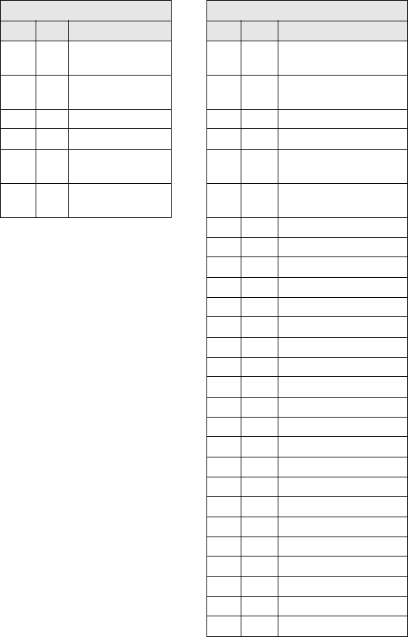
RFID Interface
LRP2000 Long Range Passice Reader/Writer 65
Example:
Reads 2 bytes of data from the tag starting at address 0001H. A
timeout of 2 seconds (07D0H = 2000 x 1 msec increments) is set for
the completion of the SN Block Read All. The Family ID byte is set to
zero so all tags will be read. Two tags respond with read data.
Command from host Response from controller
MSB LSB Remarks MSB LSB Remarks
AAH 82H Perform
Command 82
AAH 82H Command Echo/Tag 1
00H 00H Tag Family 00/
Reserved
00H 10H SN byte 1/Tag 1
00H 01H Start Address 00H 43H SN byte 2/Tag 1
00H 02H Read Length 00H 6CH SN byte 3/Tag 1
07H D0H Timeout 00H 73H SN byte 4/Tag 1
FFH FFH Message
Terminato
00H 92H SN byte 5/Tag 1
00H C0H SN byte 6/Tag 1
00H D6H SN byte 7/Tag 1
00H 54H SN byte 8/Tag 1
00H 30H Data byte 1/Tag 1
00H 31H Data byte 2/Tag 1
FFH FFH Terminator/ Tag 1
AAH 82H Command Echo/Tag 2
00H 08H SN byte 1/Tag 2
00H 0AH SN byte 2/Tag 2
00H 81H SN byte 3/Tag 2
00H 18H SN byte 4/Tag 2
00H 23H SN byte 5/Tag 2
00H CCH SN byte 6/Tag 2
00H D0H SN byte 7/Tag 2
00H EFH SN byte 8/Tag 2
00H 40H Data byte 1/Tag 2
00H 41H Data byte 2/Tag 2
FFH FFH Terminator/ Tag 2
AAH FFH Command end
02H 08H Ntags/Status
FFH FFH Message Terminator

RFID Interface
66 LRP820S-Series Long-Range Passive Reader/Writers
*******************************************************************************
ABxS Command 83H: Start/Stop Continuous SN
Read All
DESCRIPTION
Starts and stops continuous read all mode for multiple tags. It reads
the Serial Number and tag data. If the read length is zero (0), then
only the tag's serial number is read. While in this mode, any other
command can be issued and it will be handled properly. After
processing the new command, the controller will resume the
continuous read. Continuous SN Read all is started or stopped by the
start/stop Byte in the command. A one indicates it is TRUE to start
and a zero (0) indicated it is FALSE to start, or to stop continuous
read. The command has a parameter, Repeat Count, that can prevent
multiple reads of the same tag. A tag is not read a second time until
this specified number of tags have been read since it was last read.
Allowed values are from 0 to 255, where 0 means the tag can be re-
read anytime. When Start/Stop Continuous SN Read All is interrupted
with other command, the repeat count is stopped during execution of
the other commands and then resumed. The Reader/Writer will
respond with an acknowledge packet followed by data packets for
each tag read.
Field Remarks
Command Command number in hex preceded by
AAH
Family ID Tag Family ID - 00H = all tags
Reserved 00H
Start Address Tag address for the start of the read
Read Length One word for the number of bytes to be
read.
Repeat Count Number of tag that must be read before
the same tag will be read again(0-255)
Start/Stop 0001H to start, 0000H to stop
Message Terminator FFFFH
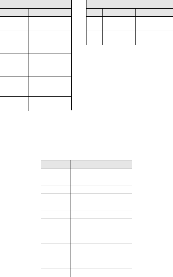
RFID Interface
LRP2000 Long Range Passice Reader/Writer 67
Example:
Starts continuous read of three bytes starting at address two, Repeat
count of four, with a family code of zero.
Command from host Response from controller
MSB LSB Remarks MSB LSB Remarks
AAH 83H Perform
Command 83
AAH 83H Command
Echo
00H 00H Tag Family 00/
Reserved Byte
FFH FFH Message
Terminator
00H 02H Start Address
00H 03H Read Length of
the data bytes
00H 04H Repeat count
00H 01H Stop/Start
continuous read.
This is to Start
FFH FFH Message
Terminator
After the controller sends the acknowledgement, it will send the data
read from the tags in the field.
Data response from controller
MSB LSB Remarks
AAH 83H Command Echo
00H 1EH Serial Number byte /Tag 1
00H 94H Serial Number byte /Tag 1
00H 0BH Serial Number byte /Tag 1
00H 01H Serial Number byte /Tag 1
00H 00H Serial Number byte /Tag 1
00H 00H Serial Number byte /Tag 1
00H 00H Serial Number byte /Tag 1
00H 01H Serial Number byte /Tag 1
00H 6CH Tag data byte /Tag 1
00H 6CH Tag data byte /Tag 1
00H 20H Tag data byte /Tag 1
FFH FFH Message Terminator

RFID Interface
68 LRP820S-Series Long-Range Passive Reader/Writers
AAH 83H Command echo
00H 4BH Serial Number byte /Tag 2
00H C5H Serial Number byte /Tag 2
00H 0BH Serial Number byte /Tag 2
00H 01H Serial Number byte /Tag 2
00H 00H Serial Number byte /Tag 2
00H 00H Serial Number byte /Tag 2
00H 00H Serial Number byte /Tag 2
00H 01H Serial Number byte /Tag 2
00H 6CH Tag data byte /Tag 2
00H 6CH Tag data byte /Tag 2
00H 20H Tag data byte /Tag 2
FFH FFH Message Terminator
AAH 83H Command echo
00H FCH Serial Number byte /Tag 3
00H C5H Serial Number byte /Tag 3
00H 73H Serial Number byte /Tag 3
00H 00H Serial Number byte /Tag 3
00H 00H Serial Number byte /Tag 3
00H 00H Serial Number byte /Tag 3
00H 00H Serial Number byte /Tag 3
00H 01H Serial Number byte /Tag 3
00H 32H Tag data byte /Tag 3
00H 33H Tag data byte /Tag 3
00H 34H Tag data byte /Tag 3
FFH FFH Message Terminator
MSB LSB Remarks

RFID Interface
LRP2000 Long Range Passice Reader/Writer 69
*******************************************************************************
ABxS Command 84H: Fill Tag All
DESCRIPTION
Fill all RFID tags-in-field or all tags in the same family with a one-Byte
value over multiple contiguous addresses.
DISCUSSION
This command is commonly used to clear an RFID tag's memory. It
writes a one-Byte value repetitively across a specified range of tag
addresses. All tags within range of the antenna with the specified
Family ID will be affected by this command. The fill function requires
one data value byte, a starting address, and a fill length. It will then
proceed to fill the tag with the data value byte, starting at the specified
start address for the specified number of consecutive bytes. The Fill
Length must be set to a non-zero value. The timeout value is given in
1 msec increments and can have a value of 001EH to FFFEH (65,534
ms). The controller will return a response after the timeout expires. A
response is returned when a successful operation is performed or
when the timeout has expired. When the timeout is set to 0, the
controller will return a syntax error.
Field Remarks
Command Command number in hex preceded
by AAH
Family Code Tag Family ID - 00H = all tags
Reserved Byte 00H
Start Address The tag address where the fill will
start
Fill Length The number of tag addresses to be
filled (1-48)
Timeout Timeout value given in 1 ms units
(001EH - FFFEH)
Data Value Byte The byte to be used as fill
Message Terminator FFFFH
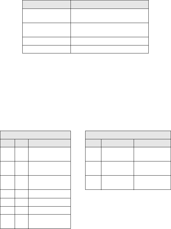
RFID Interface
70 LRP820S-Series Long-Range Passive Reader/Writers
A response to a successful command will follow this form.
Field Remarks
Command Echo Command number in hex preceded
by AAH
Number of Tags filled Number of tags found in the field
and filled
Command Status One byte Error status
Message Terminator FFFFH
Example
Writes 'A' (41H) to all tags of family 01H, starting at tag address
0005H for the following next consecutive 40 bytes with four to eight
tags expected in the field.. A timeout of 2 seconds (07D0H = 2000 x 1
msec increments) is set for the completion of the Fill All Tag. Four tags
are successfully filled within the timeout.
Command from host Response from controller
MSB LSB Remarks MSB LSB Remarks
AAH 84H Perform
Command 84
AAH 84H Command
Echo
01H 00H Tag Family 01 /
Reserved
04H 08H Ntag/Status
00H 05H Start Address FFH FFH Message
Terminator
00H 28H Fill Length
07H D0H Timeout
00H 41H Fill byte
FFH FFH Message
Terminator

RFID Interface
LRP2000 Long Range Passice Reader/Writer 71
*******************************************************************************
ABxS Command 85H: Block Read All
DESCRIPTION
Read a block of data from all RFID tags-in-field or those with the
specified Family ID.
DISCUSSION
This command is used to read segments of data from contiguous
areas of tag memory. It is capable of handling up to 1 kByte of data
transferred to the host with one command. The timeout value is given
in 1 msec increments and can have a value of 001EH to FFFEH
(65,534 ms). When the timeout is set to 0, the controller will return a
syntax error message 21H. The Block Read All consists of Tag
Family ID and Reserved Byte, a start address and number of Bytes,
followed by a timeout value and the message terminator, FFFFH. If
the read length exceeds the last tag address, the controller will return
a syntax error message 21H. The data read from the tag is returned
in the LSB of the register, and the MSB is always 00H. A special
termination packet (AAH FFH) is sent after the timeout expires. The
controller will return a response after the timeout expires. The
command returns a response after the successful operation or when
the timeout expires.
Field Remarks
Command Command number in hex preceded
by AAH
Ta g Fa m i l y Tag Family ID - 00H = all tags
Reserved Byte 00H
Start Address The tag address where the read
will start
Read Length The number of tag addresses to be
read
Timeout Timeout value given in 1 ms units
(001EH - FFFEH)
Message Terminator FFFFH
RFID Interface
72 LRP820S-Series Long-Range Passive Reader/Writers
Example:
Reads 4 bytes of data from the tag starting at address 0001H. A
timeout of 2 seconds (07D0H = 2000 x 1 msec increments) is set for
the completion of the Block Read All. The Family ID byte is set to zero
so all tags will be read. Three tags respond with read data.
Command from host Response from controller
MSB LSB Remarks MSB LSB Remarks
AAH 85H Perform
Command 85
AAH 85H Command Echo/
Tag 1
00H 02H Tag Family 00/
Index 2
00H 30H Data byte 1/Tag 1
00H 01H Start Address 00H 31H Data byte 2/Tag 1
00H 04H Read Length 00H 32H Data byte 3/
Tag 1
00H
07H D0H Timeout 33H Data byte 4/Tag 1 FFH
FFH FFH Message
Terminator
FFH Terminator/ Tag 1 AAH
85H Command Echo/
Tag 2
00H
40H Data byte 1/Tag 2 00H
41H Data byte 2/Tag 2 00H
42H Data byte 3/Tag 2 00H
43H Data byte 4/Tag 2 FFH
FFH Terminator/ Tag 2 AAH
85H Command Echo/
Tag 3
00H
34H Data byte 1/Tag 3 00H
35H Databyte 2/Tag 3 00H
36H Data byte 3/Tag 3 00H
37H Data byte 4/Tag 3 FFH
FFH Terminator/ Tag 3 AAH
FFH Termination Packet 03H
08H Ntag/Status FFH
FFH Terminator
Message

RFID Interface
LRP2000 Long Range Passice Reader/Writer 73
*******************************************************************************
ABxS Command 86H: Block Write All
DESCRIPTION
Write a block of data to all RFID tags or all tags with the same Family
ID.
DISCUSSION
This command is used to write segments of data to contiguous areas
of tag memory. It is capable of transferring up to 1 kByte of data from
the Host with one command. The timeout value is given in 1 msec
increments and can have a value of 001EH to FFFEH (65,534 ms).
When the timeout is set to 0, the controller will return a syntax error.
The BlockWrite consists of a Tag Family ID and an Reserved Byte,
start address followed by the data stream to be written to the RFID
tag. If the write range exceeds the last tag address, the controller wil
return error message 21H, invalid format. The data to be written to
the tag is contained in the LSB of the register, and the MSB is always
00H. The controller returns a response when the timeout expires. The
controller returns a response when the timeout expires.
Field Remarks
Command Command number in hex preceded
by AAH
Family ID Tag Family ID - 00H = all tags
Reserved 00H
Start
Address
The tag address where the write will
start
Write Length The number of tag addresses to be
written to in bytes
Timeout Timeout value given in 1 ms units
(001EH - FFFEH)
Write Data The data to be written
Message Terminator FFFFH

RFID Interface
74 LRP820S-Series Long-Range Passive Reader/Writers
Example:
Writes 4 bytes of data, starting at address 0001H. A timeout of 2
seconds (07D0H = 2000 x 1 msec increments) is set for the
completion of the Block Write. The Family ID byte is set to 2, so all
tags with Family ID of 2 will be written to (four tags in this example).
Command from host Response from controller
MSB LSB Remarks MSB LSB Remarks
AAH 86H Perform Command 86 AAH 86H Command
Echo
02H 00H Tag Family/Reserved 04H 08H Ntags/Status
00H 01H Start Address FFH FFH Message
Terminator
00H 04H Write Length MSB LSB Remarks
07H D0H Timeout AAH 86H Command
Echo
00H 40H Data byte 1 04H 08H Ntags/Status
00H 41H Data byte 2 FFH FFH Message
Terminator
00H 42H Data byte 3 MSB LSB Remarks
00H 43H Data byte 4 AAH 86H Command
Echo
FFH FFH Message Terminator 04H 08H Ntags/Status

RFID Interface
LRP2000 Long Range Passice Reader/Writer 75
*******************************************************************************
ABxS Command 87H: Read Tag SN All
DESCRIPTION
This command retrieves the 8-byte tag serial number from all tags o r
those with the specified Family ID number.
DISCUSSION
Each ISO-15693 compliant tag has an unique (over 280 trillion
possibilities) serial number. This number cannot be changed and is
not part of the available data bytes. The tag serial number is returned
in the LSB only, with the MSB as 00H. The timeout value is given in 1
msec increments and can have a value of 001EH to FFFEH (65,534
ms). When the timeout is set to 0, the controller will return a syntax
error. A special termination packet (starting with AAH FFH) is sent
when the timeout expires. A response is returned after successful
operation or after the timeout has expired.
Field Remarks
Command Command number in hex preceded
by AAH
Family ID Tag Family ID - 00H = all tags
Reserved 00H
Timeout Timeout value given in 1 ms units
(001EH - FFFEH)
Message Terminator FFFFH
RFID Interface
76 LRP820S-Series Long-Range Passive Reader/Writers
Example
This example will read the 8-byte serial number from Tag Family 2. In
this example the ID for the found tag is 1E6E3CD200000000H in
hexadecimal. Multiple tags will return a complete response packet for
each tag.
Command from host Response from controller
MSB LSB Remarks MSB LSB Remarks
AAH 87H Perform Command 87 AAH 87H Command Echo
01H 00H Family ID/Reserved 00H 1EH First SN byte
07H D0H Timeout 00H 6EH Second SN byte
FFH FFH Message Terminator 00H 3CH Third SN byte
00H D2H Fourth SN byte
00H 00H Fifth SN byte
00H 00H Sixth SN byte
00H 00H Seventh SN byte
00H 00H Eighth SN byte
FFH FFH Message
Terminator
AAH FFH Termination
packet
01H 08H Ntags/Status
FFH FFH Message
Terminator
RFID Interface
LRP2000 Long Range Passice Reader/Writer 77
*******************************************************************************
ABxS Command 88H: Tag Search All
DESCRIPTION
Check to see if there is an RFID tag within range of the antenna.
DISCUSSION
This command will activate controller to "look" for a tag in range. As
soon as the controller finds a tag it will return a command echo to the
host. The timeout value is given in 1 msec increments and can have a
value of 001EH to FFFEH (65,534 ms). When the timeout is set to 0,
the controller will return a syntax error. The number of tags returned
can be either 1 (tag found) or 0 (timeout expired without having found
a tag).
Field Remarks Command
Command number in
hex preceded by AAH
Family ID Tag Family ID - 00H =
all tags
Reserved 00H Timeout Timeout value given in
1 ms units (001EH -
FFFEH)
Message Terminator FFFFH

RFID Interface
78 LRP820S-Series Long-Range Passive Reader/Writers
Example
Checks for an RFID tag in the RF field. A timeout of 1 seconds
(07D0H = 2000 x 1 msec increments) is set for the completion of the
Tag Search. The Family ID is set for any tag. One tag is found and the
command is successful.
Command from host Response from controller
MSB LSB Remarks MSB LSB Remarks
AAH 88H Perform
Command 88
AAH 88H Command
Echo
00H 00H Family ID/
Reserved
01H 00H Ntags/Status
07H D0H 2 second Timeout FFH FFH Message
Terminator
FFH FFH Message
Terminator