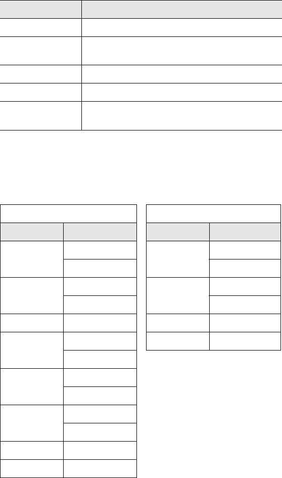
Contents
- 1. Manual R5
- 2. Manual R2
Manual R5

OPERATOR’S MANUAL
LRP75 Long Range
Passive
Reader/Writer
Manual Revision 5, 9-02
Publication # 17-1289
Escort Memory Systems Warranty
Escort Memory Systems warrants that all products of its own manufacture conform to Escort Memory Sys-
tems specifications and are free from defects in material and workmanship when used under normal operat-
ing conditions and within the service conditions for which they were furnished. The obligation of Escort
Memory Systems hereunder shall expire one (1) year after delivery, unless otherwise specified, and is limited
to repairing, or at its option, replacing without charge, any such product which in Escort Memory System's
sole opinion proves to be defective within the scope of this Warranty. In the event Escort Memory Systems is
not able to repair or replace defective products or components within a reasonable time after receipt thereof,
Buyers shall be credited for their value at the original purchase price. Escort Memory Systems must be noti-
fied in writing of the defect or nonconformity within the warranty period and the affected product returned to
Escort Memory Systems factory or to an authorized service center within thirty (30) days after discovery of
such defect or nonconformity. Shipment shall not be made without prior authorization by Escort Memory
Systems.
This is Escort Memory Systems' sole warranty with respect to the products delivered hereunder. No state-
ment, representation, agreement or understanding oral or written, made by an agent, distributor, representa-
tive, or employee of Escort Memory Systems which is not contained in this warranty, will be binding upon
Escort Memory Systems, unless made in writing and executed by an authorized Escort Memory Systems
employee. Escort Memory Systems makes no other warranty of any kind whatsoever, expressed or implied,
and all implied warranties of merchantability and fitness for a particular use which exceed the aforestated
obligation are hereby disclaimed by Escort Memory Systems and excluded from this agreement. Under no
circumstances shall Escort Memory Systems be liable to Buyer, in contract or in tort, for any special, indirect,
incidental, or consequential damages, expenses, losses or delay however caused.
Equipment or parts which have been subject to abuse, misuse, accident, alteration, neglect, unauthorized
repair or installation are not covered by warranty. Escort Memory Systems shall make the final determination
as to the existence and cause of any alleged defect. No liability is assumed for expendable items such as
lamps and fuses. No warranty is made with respect to custom equipment or products produced to Buyer's
specifications except as specifically stated in writing by Escort Memory Systems in the contract for such cus-
tom equipment.
This warranty is the only warranty made by Escort Memory Systems with respect to the goods delivered
hereunder, and may be modified or amended only by a written instrument signed by a duly authorized officer
of Escort Memory Systems and accepted by the Buyer.
Extended warranties of up to four years are available for purchase for most EMS products. Contact EMS or
your distributor for more information.
This document contains proprietary information which is protected by copyright. All rights are reserved. The
information in this manual has been carefully checked and is believed to be accurate; however, no responsi-
bility is assumed for possible inaccuracies or omissions. Specifications are subject to change without notice.
EMS©, Escort Memory Systems™ and the EMS © logo are registered trademarks of Escort Memory Sys-
tems, a Datalogic Group Company. Other brand and product names mentioned are trademarks or registered
trademarks of their respective holders.
Escort Memory Systems
A Datalogic Group Company
170 Technology Circle
Scotts Valley, CA 95066
Telephone (831) 438-7000
FAX (831) 438-5768
www.ems-rfid.com
email: info@ems-rfid.com

LRP75 Long Range Passive Reader/Writer i
Chapter 1 Getting Started
1.1 Introduction. . . . . . . . . . . . . . . . . . . . . . . . . . . . . . . . . . . . . . . . . . 1
1.2 Unpacking and Inspection . . . . . . . . . . . . . . . . . . . . . . . . . . . . . . 1
1.3 FCC Compliance . . . . . . . . . . . . . . . . . . . . . . . . . . . . . . . . . . . . . 2
1.4 Changes and Modifications . . . . . . . . . . . . . . . . . . . . . . . . . . . . . 2
Chapter 2 Mechanical Specifications
2.1 Dimensions. . . . . . . . . . . . . . . . . . . . . . . . . . . . . . . . . . . . . . . . . . 3
2.2 Mounting Options . . . . . . . . . . . . . . . . . . . . . . . . . . . . . . . . . . . . . 3
2.3 RF Range and Orientation . . . . . . . . . . . . . . . . . . . . . . . . . . . . . . 4
2.4 Locating the LRP75 . . . . . . . . . . . . . . . . . . . . . . . . . . . . . . . . . . . 4
2.4.1 Guidelines . . . . . . . . . . . . . . . . . . . . . . . . . . . . . . . . . . . . 5
Chapter 3 Power and Electrical Interface
3.1 Internal Junction Blocks . . . . . . . . . . . . . . . . . . . . . . . . . . . . . . . . 7
3.2 Power . . . . . . . . . . . . . . . . . . . . . . . . . . . . . . . . . . . . . . . . . . . . . . 7
3.2.1 Requirement . . . . . . . . . . . . . . . . . . . . . . . . . . . . . . . . . . 7
3.2.2 Connections . . . . . . . . . . . . . . . . . . . . . . . . . . . . . . . . . . . 8
3.3 Serial Communications. . . . . . . . . . . . . . . . . . . . . . . . . . . . . . . . . 8
3.4 RS232/RS422 Interface . . . . . . . . . . . . . . . . . . . . . . . . . . . . . . . . 8
3.5 Serial Connections . . . . . . . . . . . . . . . . . . . . . . . . . . . . . . . . . . . . 9
3.5.1 RS232 and Power Cable . . . . . . . . . . . . . . . . . . . . . . . . 10
3.5.2 Wiring . . . . . . . . . . . . . . . . . . . . . . . . . . . . . . . . . . . . . . . 10
3.6 LED Indicator . . . . . . . . . . . . . . . . . . . . . . . . . . . . . . . . . . . . . . . 11
Chapter 4 Configuration Menu
4.1 Introduction. . . . . . . . . . . . . . . . . . . . . . . . . . . . . . . . . . . . . . . . . 13
4.1.1 Using the EC Program . . . . . . . . . . . . . . . . . . . . . . . . . . 13
4.2 Configuration Menu . . . . . . . . . . . . . . . . . . . . . . . . . . . . . . . . . . 13
4.2.1 Set COM1 Parameters . . . . . . . . . . . . . . . . . . . . . . . . . . 14
4.2.2 Set Operating Mode . . . . . . . . . . . . . . . . . . . . . . . . . . . . 14
4.2.3 Download Software Updates . . . . . . . . . . . . . . . . . . . . . 16
Chapter 5 Standard RFID Interface
5.1 Introduction. . . . . . . . . . . . . . . . . . . . . . . . . . . . . . . . . . . . . . . . . 17
5.2 Command Timeout Values . . . . . . . . . . . . . . . . . . . . . . . . . . . . . 17
5.3 Address Blocks. . . . . . . . . . . . . . . . . . . . . . . . . . . . . . . . . . . . . . 18
5.4 ABx Error Codes. . . . . . . . . . . . . . . . . . . . . . . . . . . . . . . . . . . . . 19
5.4.1 ABx Standard Error Format . . . . . . . . . . . . . . . . . . . . . . 20
5.5 Command Descriptions . . . . . . . . . . . . . . . . . . . . . . . . . . . . . . . 20
5.6 ABx Standard Commands . . . . . . . . . . . . . . . . . . . . . . . . . . . . . 20
5.6.1 Command 4 (04 Hex): Tag Fill . . . . . . . . . . . . . . . . . . . . 20
5.6.2 Command 5 (05 Hex): Block Read . . . . . . . . . . . . . . . . 22
5.6.3 Command 6 (06 Hex): Block Write . . . . . . . . . . . . . . . . . 24
5.6.4 Command 7 (07H): Read Tag Serial Number . . . . . . . . 25
5.6.5 Command 8 (08 Hex): Tag Search . . . . . . . . . . . . . . . . 26
Table of Contents
Table of Contents
ii LRP75 Long Range Passive Reader/Writer
5.6.6 Command D (0D Hex): Start/Stop Continuous
Block Read . . . . . . . . . . . . . . . . . . . . . . . . . . . . . . . . . . 27
5.6.7 Command E (0EH) Read SN and Data . . . . . . . . . . . . . 30
5.6.8 Command F (0FH) Start/Stop Continuous Read
SN and Data . . . . . . . . . . . . . . . . . . . . . . . . . . . . . . . . . 31
5.7 ABx Fast Commands. . . . . . . . . . . . . . . . . . . . . . . . . . . . . . . . . 33
5.7.1 ABx Command Packet Structure . . . . . . . . . . . . . . . . . 33
5.7.2 Command 4 (04 Hex): Tag Fill . . . . . . . . . . . . . . . . . . . 35
5.7.3 Command 5 (05 Hex): Block Read . . . . . . . . . . . . . . . . 38
5.7.4 Command 6 (06 Hex): Block Write . . . . . . . . . . . . . . . . 40
5.7.5 Command 7 (07H): Read Tag Serial Number . . . . . . . . 42
5.7.6 Command 8 (08 Hex): Tag Search . . . . . . . . . . . . . . . . 44
5.7.7 Command D (0D Hex): Start/Stop Continuous
Block Read . . . . . . . . . . . . . . . . . . . . . . . . . . . . . . . . . . 45
5.7.8 Command E (0EH) Read SN and Data . . . . . . . . . . . . . 49
5.7.9 Command F (0FH) Start/Stop Continuous Read
SN and Data . . . . . . . . . . . . . . . . . . . . . . . . . . . . . . . . . 51
Appendix A Technical Specifications
A.1 Electrical Characteristics . . . . . . . . . . . . . . . . . . . . . . . . . . . . . 55
A.2 Physical Characteristics . . . . . . . . . . . . . . . . . . . . . . . . . . . . . . 55
A.3 Environmental . . . . . . . . . . . . . . . . . . . . . . . . . . . . . . . . . . . . . . 55
A.4 Communication Characteristics . . . . . . . . . . . . . . . . . . . . . . . . 55
Appendix B LRP75 Beta Connections
B.1 Internal Junction Blocks . . . . . . . . . . . . . . . . . . . . . . . . . . . . . . 57
B.2 Power Connections . . . . . . . . . . . . . . . . . . . . . . . . . . . . . . . . . . 57
B.3 Serial Connections . . . . . . . . . . . . . . . . . . . . . . . . . . . . . . . . . . 58
Appendix C Models and Accessories................................ 59
Appendix D ASCII Chart............................................................. 61

LRP75 Long Range Passive Reader/Writer 1
1
Getting Started
1.1 Introduction
Escort Memory Systems' passive read/write system is a complete
family of field-proven read/write Radio-Frequency Identification
products.
The system consists of RFID tags, reader/writers, antennas,
controllers, bus interfaces, and ancillary equipment. Tags can be
attached to a product or its carrier and act as an electronic identifier,
job sheet, portable database, or manifest. Tags are read and updated
via an Escort Memory Systems Reader/Writer, through any non-
conducting material, while moving or standing still.
Escort Memory Systems' LRP-Series long range passive RFID
system is the latest in our line of high performance, industrial RFID
equipment. The passive design of the LRP read/write system uses the
RF field from the antenna to power the tag, eliminating the need for
tag batteries. The LRP passive read/write system is designed to
provide cost effective RFID data collection and control solutions to
automation and material handling applications.
The LRP system uses the internationally recognized ISM frequency of
13.56 MHZ to both power the tag, and to establish a radio link to
transfer the information. LRP-Series passive tags provide 48 bytes of
reprogrammable memory.
The LRP75 is encased in a NEMA2 enclosure. The LRP75 is
equipped with an internal antenna that has a range of 4 inches.
The LRP75 has one serial port that supports RS232 or RS422 serial
communications. The serial port is used to receive commands and
software from the host and to send the data back.
1.2 Unpacking and Inspection
When you unpack the LRP75, retain the original shipping carton and
packing material in case any item has to be returned to Escort
Memory Systems. Inspect each item carefully for evidence of
damage. If any item appears to be damaged, notify your Escort
Memory Systems representative immediately.
The following is supplied with the LRP75:
1 LRP75
2 Short screws
2 Long screws
2 Threaded inserts
Getting Started
2LRP75 Long Range Passive Reader/Writer
The following components are required for configuring a complete
system:
• LRP-Series Passive Read/Write Tags
• LRP75-to-host cable (user-supplied)
• RS232/RS422 host
• 24 Vdc +/- 10%, 5 W power supply
1.3 FCC Compliance
This equipment has been tested and found to comply with the limits
for a Class B digital device, pursuant to Part 15 of the FCC Rules.
These limits are designed to provide reasonable protection against
harmful interference in a residential installation. This equipment
generates, uses and can radiate radio frequency energy and, if not
installed and used in accordance with the instructions, may cause
harmful interference to radio communications. However, there is no
guarantee that interference will not occur in a particular installation. If
this equipment does cause harmful interference to radio or television
reception, which can be determined by turning the equipment off and
on, the user is encouraged to try to correct the interference by one or
more of the following measures:
• Reorient or relocate the receiving antenna.
• Increase the separation between the equipment and receiver.
• Connect the equipment into an outlet on a circuit different from that
to which the receiver is connected.
• Consult the dealer or an experienced radio/TV technician for help.
1.4 Changes and Modifications
Any changes or modifications to the LRP75 not expressly approved
by Escort Memory Systems, could void the user's authority to operate
the equipment.
LRP75 Long Range Passive Reader/Writer 3
2
Mechanical Specifications
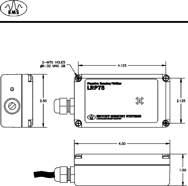
2.1 Dimensions
Figure 2-1 shows the dimensions and mounting hole locations for the
LRP75 Reader/Writer.
Figure 2-1. LRP75 dimensions and mounting hole locations
2.2 Mounting Options
The LRP75 ships with mounting screws and threaded inserts to
provide mounting options. The LRP75 can be through-bolted with the
two longer screws or mounted with an adhesive backing such as
Velcro.®
If you do not use the long screws to through-bolt the LRP75, you
should install the threaded inserts and use the short screws to secure
the lid.
To install the threaded inserts:
1. Place the LRP75 upside down on a firm surface.
2. Place the threaded inserts, smooth end first, into the two holes
and press in firmly.
3. From the lid side of the LRP75, insert the screws and tighten them
until the inserts are flush with the bottom of LRP75.
Mechanical Specifications
4LRP75 Long Range Passive Reader/Writer
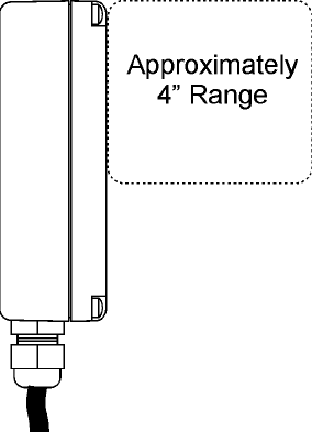
2.3 RF Range and Orientation
The following information should be considered when positioning the
LRP75. The path of the tags through the RF field should be within the
guaranteed reading/writing range unless sufficient site testing has
been performed to assure consistent RF communications.
Figure 2-2. LRP75 reading range
2.4 Locating the LRP75
The reading range of the LRP75 is primarily affected by two
environmental variables. The first, and most influential of these
variables, is the presence of metal or any other electrically conductive
material within the range of the antenna. The reader can be safely
mounted to a metal surface without compromising the reading range;
however, any conductive material within the area in front of and to the
sides of the reader - anywhere a tag can be read - will affect the
reading range to some extent. The most reliable method for
determining the effects of metal on the reading range is to perform site
tests.
Electromagnetic radiation is the second environmental variable that
affects the reading range and overall performance of the LRP75. The
reader should not be located close to any sources of electromagnetic
radiation. Do not mount a LRP75 closer than two meters from another
LRP75, and a greater distance from longer-range readers, such as the
EMS LRP820. Again, site testing will provide the most reliable means
to determine the read range in a given environment.
Mechanical Specifications
LRP75 Long Range Passive Reader/Writer 5
2.4.1 Guidelines
• Isolate the LRP75 from electromagnetic radiation.
• Avoid surrounding the LRP75 with metal.
• Maintain at least two meters spacing between adjacent LRP75s.
• Stay within the guaranteed range of the tag you are using.
• Conform with EIA RS232 and RS422 standards.
Mechanical Specifications
6LRP75 Long Range Passive Reader/Writer
This page left blank intentionally.
LRP75 Long Range Passive Reader/Writer 7
3
Power and Electrical Interface
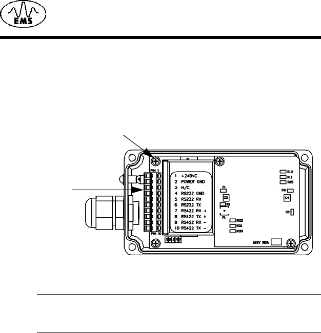
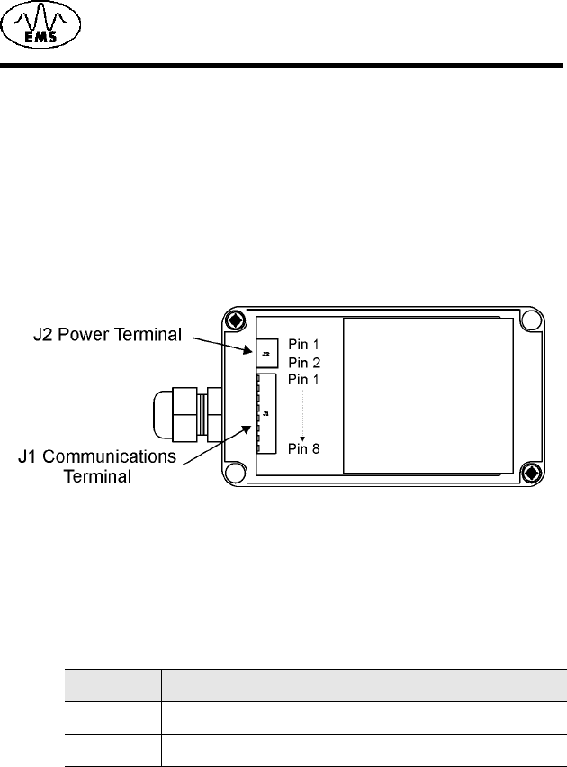
3.1 Internal Junction Blocks
The LRP75 is connected to external power and communications
cabling through an internal terminal strip. The power and serial
communication junction block (J1) has 10 terminals and accepts AWG
22-14 wires.
Figure 3-1. Internal junction block
NOTE:Earlier models of the LRP75 have different power and serial
communications connections. For more information, see
Appendix B,
LRP75 Beta Connections
.
3.2 Power
3.2.1 Requirement
The LRP75 power supply requirements are:
• 24 Vdc +/- 10%
• 5 Watts maximum consumption
The maximum current consumption at 24 Vdc is 200 mA.
J1 Terminal Block
Ground Screw

Power and Electrical Interface
8LRP75 Long Range Passive Reader/Writer
3.2.2 Connections
Connection to DC power is through pins 1 and 2 of the internal
terminal block J1.
3.3 Serial Communications
The LRP75 offers either RS232 or RS422 communications. The
RS422 option provides the superior reliability over longer distances or
in noisy environments. Communication parameters, such as baud
rate, are set by the configuration program.
CAUTION:Do not bundle communications wiring with high current
power lines. This will cause communications errors.
3.4 RS232/RS422 Interface
The LRP75 is set to automatically enter run mode seven seconds
after power-on the device. This allows you to enter the configuration
program by entering a <control D> after power-on. If no commands
are received by the reader/writer during the seven seconds, the
LRP75 enter run mode with existing operating parameters. For more
information on the Configuration Menu refer to Chapter 4.
To communicate with the device via RS232, set the serial
communications parameters of the host as follows:
Baud rate 9600
Parity none
Data bits 8
Stop bit 1
NOTE:The LRP75 automatically resets to 9600, N, 8,1 for seven
seconds whenever the power is cycled, after which it will apply
the setting made in the configuration menu.
Table 3-1: J1 Power Connections
Terminal Description
1+24 Vdc
2 Power Ground

Power and Electrical Interface
LRP75 Long Range Passive Reader/Writer 9
3.5 Serial Connections
The LRP75 can be wired to communicate with the host either through
an RS232 or RS422 interface. Connection to the serial interface is
through the J1 terminal shown in Figure 3-1 on page 7.
Table 3-2 gives the pinouts for the J1 terminal block.
NOTE:In order to configure the unit for RS422, you must first
establish communications through RS232 and update the
communication parameters.
The signals and electrical loads should conform to the electrical
specifications of EIA Standard for RS232 or RS422. The maximum
cable length specified for RS232 is 50 feet. Use the RS422 interface
for longer communications links. Use high quality shielded cable for
these connections.
Table 3-2: J1 Serial Communications Pinouts
Terminal Function
3 Reserved, no connection
4 Signal Ground (DB9, pin 5)
5 RS232 RX (wired to host DB9, pin 3)
6 RS232 TX (wired to host DB9, pin 2)
7RS422 RX +
8RS422 TX +
9RS422 RX -
10 RS422 TX -
Power and Electrical Interface
10 LRP75 Long Range Passive Reader/Writer
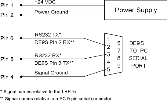
3.5.1 RS232 and Power Cable
Figure 3-2 shows how to construct a demonstration cable with power
and RS232 serial communications to a PC host with a DE9 serial port
connector.
Figure 3-2. LRP75 to PC host demo
3.5.2 Wiring
Use shielded cable only. Connect shield drain of the power and data
cabling to either ground on the J1 connector (terminal 2 or 4).
• Recommended cable for RS422 is Belden 3107A, 3108A or
compatible.
• Recommended cable for RS232 is Belden 9941 or compatible.
To fully comply with FCC and CE Regulations, wind the power and
data cabling around a type 43 ferrite toroid such as Fairrite™ part
number 2643803802 or Amidon™ part number FT-240-43. Install the
toroid as close as possible to the LRP75’s gland nut. You must
connect the internal ground screw, shown in Figure 3-1 on page 7, to
the nearest earth ground outside the unit.
To make the ground connection, first terminate a length of 1/8-inch
copper braid with a ring terminal such as Panduit™ part number P18-
45. Fasten the ring terminal to the ground screw. For a tight seal,
chase the braid through the gland nut against the data and power
cabling.

Power and Electrical Interface
LRP75 Long Range Passive Reader/Writer 11
To connect your cable to the LRP75:
1. Remove the cover of the antenna by loosening the four captive
screws.
2. Loosen the cord grip, feed the cable through the cord grip and
attach the wires to the terminal screws. Tighten the cord grip to
seal the cable. Use a cable of sufficient diameter to properly seal
with the cord grip. The recommended minimum O.D. is .125
inches (3.2 mm).
NOTE:Due to the small size of the LRP75 enclosure and gland nut,
you may have difficulty sealing wires passing through the
gland nut. Olflex® cable part number 911285 is readily
available and will satisfy the requirements of most applications.
3. Re-assemble the enclosure and secure the screws.
3.6 LED Indicator
The LRP75 has one bi-color LED indicating power on and activity on
the serial port. Table 3-3 shows the LED activity and meaning.
Table 3-3: LRP75 LED Indicator
LED Action LRP75 state Description
Slow RED
Blink
Power-up or
reset
The LED will flash RED slowly for about
seven seconds following power-up
during which time the user may send a
<Ctrl> D to enter configuration mode.
Fast RED
Blink
Configuration
mode
If the LRP75 receives a <Ctrl> D during
the initial seven second period, the LED
will flash at a faster rate until
configuration mode has been exited.
Steady
GREEN
Idle The unit is ready for an ABx command.
A steady GREEN LED indicates that the
seven second period has elapsed
without entering configuration mode, or
configuration has been completed.
GREEN
Blink
LRP75
upgrade
While downloading a new, or custom,
program to the LRP75, the LED will
blink GREEN.
Short RED/
GREEN
Blink
Executing
Command
While the reader/writer is occupied with
a command, the LED will be flashing
GREEN to RED. A RED to GREEN
flash indicates a tag is being searched
for, and the command is being
executed.

Power and Electrical Interface
12 LRP75 Long Range Passive Reader/Writer
RED and
GREEN
Executing
Continuous
Block Read
The LED will be both RED and GREEN
(orange) indicates the LRP75 is in
continuous mode. There is short RED
flash when data sent to the host.1
1. When Software Handshaking is enabled, and the host has sent
the LRP75 an XOFF, the RED LED will be on while the LRP75
transmit buffer fills. The LED will remain RED until an XON is
received and the LRP buffer is emptied.
Table 3-3: LRP75 LED Indicator
LED Action LRP75 state Description

LRP75 Long Range Passive Reader/Writer 13
4
Configuration Menu
4.1 Introduction
The LRP75 contains a configuration program in EEPROM memory for
defining the data format and serial protocol. After the LRP75 has been
powered, it pauses for seven seconds waiting for the command to
enter the configuration program. The communication parameters
during this seven second period are:
• 9600 baud
• 8 data bits
•No parity
• 1 stop bit
Use a terminal emulation program (such as EC or HyperTerminal) to
send a <control D> within this seven second period to initialize the
Configuration Menu. If the LRP75 does not receive a <control D>, it
will go "online" with the existing user-defined settings.
4.1.1 Using the EC Program
The terminal emulation program, EC.EXE, is recommended for
LRP75/Host communications. It can be downloaded from Escort
Memory Systems Web site (www.ems-rfid.com). Unlike many other
terminal emulation programs, EC.EXE can transfer binary data in
ASCII hex-based format, as required by the LRP75 commands. The
.HEX file downloads to the LRP are in Intel Hex format.
4.2 Configuration Menu
The Configuration Menu will display the current state of the operating
parameters. To change a parameter, enter the decimal number shown
in the menu for the option you want. An invalid entry will return you to
the Main Menu.
Configuration Menu
14 LRP75 Long Range Passive Reader/Writer
The Main Board Configuration menu displays the current main board
software version number together with the RFID firmware version.
******** LRP75/76 Standard Program V1.3E ********
RF module:4.01J
Serial Port COM1:RS232, 9600, N, 8, 1 No Handshake
Operating Mode:ABx Standard
Tag Type: Phillips I-CODE 1
[1] Set COM1 Parameters
[2] Set Operating Mode
[3] Set Tag Type
[4] Restore Factory Defaults
[5] Download New Program
[6] Download RFID Firmware
[7] Exit to Operating Mode
Enter Selection:
4.2.1 Set COM1 Parameters
The Set COM1 Parameters menu is given below.
*** Set COM1 Parameters **
Operating mode? [0] RS232 [1] RS422
Baud Rate? [0] 1200 [1] 2400 [2] 4800 [3] 9600 [4] 19200
Data size? [0] 7bit [1] 8bit
Parity? [0] None [1] Even [2] Odd
Handshake [0] None [1] Xon/Xoff
Save Changes to EEPROM? [0] No [1] Yes
Enter the number corresponding to the parameter you wish to enable.
4.2.2 Set Operating Mode
The Set Operating Mode menu is given below.
*** Set Operating Mode ***
Commands Protocol? [0] ABx Standard [1] ABx Fast
Checksum? [0] Disabled [1] Enabled
Power up performing Continuous Read?
[0] NO
[1] Continuous Block Read (0DH) active
[2] Continuous Read SN and Data (0FH) active
-> 1
Start Address (0 to 47) 0
Length (1 to 48) 48
Delay Between Duplicate Decodes (0 to 60) 1
Raw Read Response? [0] NO [1] CR terminate [2] CR/LF
terminate 2
Save Changes to EEPROM? [0] No [1] Yes
Configuration Menu
LRP75 Long Range Passive Reader/Writer 15
The LRP75 supports ABx Standard and ABx Fast RFID command
protocols. Select your command protocol from this menu. If you select
ABx fast, you can select an optional checksum. For data delivery
verification to the host, it is recommended to have the checksum
enabled.
You can also select from three Run Mode types. The options are:
[0] NO
LRP75 will wait for an ABx command after reset. If you choose 0
(NO), then the LRP75 configuration is complete and you are given the
option to save the settings.
[1] Continuous Block Read (0DH) active
After reset, the LRP75 will be in Continuous Block Read Mode just as
if you had issued a Continuous Block Read (0DH) to the LRP75. You
must enter the tag start address, read length, and the delay between
identical decodes values.
[2] Continuous Read SN and Data (0FH) active
After reset, the LRP75 will be performing Continuous Read SN Data.
This is the same as if the 0FH command had been issued to the
LRP75. You must enter the tag start address, read length, and the
delay between identical decodes values.
Raw Read Response
It is possible to set the LRP75 to only send raw tag data to the host.
The raw read data does not contain a header, length, command
number, or terminator. If the data on the tag is all printable ASCII, then
the entire packet can be printed on any terminal emulator or EC.
To receive a raw read response, the LRP75 must be set to use ABx
Fast, and to start in Continuous Block Read Run Mode.
Raw Read Response? [0] NO [1] CR terminate [2] CR/LF
terminate
If you choose the raw response option 0 (NO), then standard ABx
response packets are returned when a tag is read. If you choose
option 1 or 2 (CR or CR/LF terminate), then the entire header and
footer are removed from the response.
If you choose CR or CR/LF, then a carriage return (0DH) or carriage
return line feed (0DH, 0AH) is append to the raw string of data from
the tag. There is no header, length, command echo, footer, or
checksum in this response string. Raw Read Response does not
allow any delivery or data verification.
Configuration Menu
16 LRP75 Long Range Passive Reader/Writer
4.2.3 Download Software Updates
The mircocontroller software can be updated by entering the
'Download New Program' mode and sending an Intel Hex file.
Also, the RF firmware can be updated, by means of the 'Download RF
firmware' mode. Use the HFD.EXE Windows application on the PC.
Detailed download instructions are supplied with any custom or
upgrade software.
LRP75 Long Range Passive Reader/Writer 17
5
Standard RFID Interface
5.1 Introduction
The LRP75 features RFID commands to perform the reading/writing
of tag data. The standard commands are based on the established
ABx protocol. Table 5-1 lists the standard commands available in the
LRP75.
The LRP75 stores incoming bytes in a buffer and scans for a start
character (AA Hex or <STX><STX>). When a start character is found,
it will check for the terminating character (FFFF Hex or <ETX>).
Having identified a potentially valid command string, the standard
program will check the format of the data and either perform the
requested function or generate an error message.
5.2 Command Timeout Values
Most commands sent to the LRP75 contain a timeout value field. This
is the maximum number of milliseconds that a command will be
attempted. If a command is not successfully completed within this
time interval, a tag search error (08H) will be returned. When a
command is successfully completed, the appropriate command
response will be returned to the host. This will happen in less time
than the timeout period.
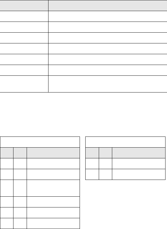
Table 5-1: Standard RFID Commands
Command Hex
Equivalent Command Name
04 Hex Tag Fill
05 Hex RF Port Block Read
06 Hex RF Port Block Write
07 Hex Read Tag Serial Number
08 Hex Tag Search
0D Hex Start/Stop Continuous Block Read
0E Hex Read SN and Data
0F Hex Start/Stop Continuous Read SN and Data

Standard RFID Interface
18 LRP75 Long Range Passive Reader/Writer
For practical reasons (wakeup time, overhead) timeout values less
than 30 ms have negligible affects on LRP75 behavior. Therefore, the
examples given in this manual present the timeout range as 1EH to
FFFEH (30 to 65,534 ms).
Specifying a long timeout will not necessarily affect the time required
to complete a command, but merely instructs the LRP75 how long to
attempt the command before aborting. The timeout error is returned
only if the command can not be successfully executed. For example,
when the tag is not currently in the field.
Using a zero timeout value is not permitted and will return a syntax
error (21H).
NOTE:During write commands, the tag must remain in the field until
either the command completes successfully, or the timeout
period has expired. If a write command is initiated with a tag in
the antenna's active field and then the tag leaves the field
before the command has completed or times out, data may be
lost or corrupted. It is recommended that you use the longest
timeout value permitted by the application.
For applications where the tag positioning may not be controlled and
the tag movement cannot be limited to the antenna field, longer
timeouts and retries should be utilized in the application program. This
will ensure the highest success rates.
If an application demands the tag to travel at high speeds and retries
can not be utilized, it may be required to synchronize the tag travel
speed with the command timeouts. Use of a presence sensor may be
required to ensure that the LRP75 cannot timeout while the tag is
passing by. Many factors need to be considered for high speed
applications such as; address range, command type, tag and antenna
models, and the installation environment. Please contact Escort
Memory Systems' application support team for help with your
application.
5.3 Address Blocks
All read/write operations between the tag and the LRP75 are based
on 4-byte block transfers. Each operation, whether it invokes a single
data byte or 48 bytes, will read/write in multiples of four bytes.
This fact impacts timing issues in two cases:
• When the number of data bytes is not a multiple of 4.
• When the read or write does not start on one of the first block bytes
(0, 4, 8 and so on).

Standard RFID Interface
LRP75 Long Range Passive Reader/Writer 19
In the first case, the RFID interface will first read all tag addresses
affected by the transaction so that data not requested by the host is
not returned or written to. For example, when you request a write to
tag addresses 2 through 5 (4 bytes), the LRP will first read the tag
data at addresses 0 through 7 (8 bytes), and then write to those
addresses with the new data in addresses 2 through 5.
When a write or read operation is executed at a starting address other
than the first byte of a block, the blocks with partial data will also be
included in the operation. For example, a four byte read from an odd
address will take twice as long since the LRP75 will read 8 bytes.
NOTE:To make your application as efficient as possible, design your
tag accesses in 4-byte blocks starting on a the first byte of a
block.
5.4 ABx Error Codes
The LRP75 returns an error if it encounters a fault during operation.
Table 5-2 list the possible error codes in Hexadecimal format.
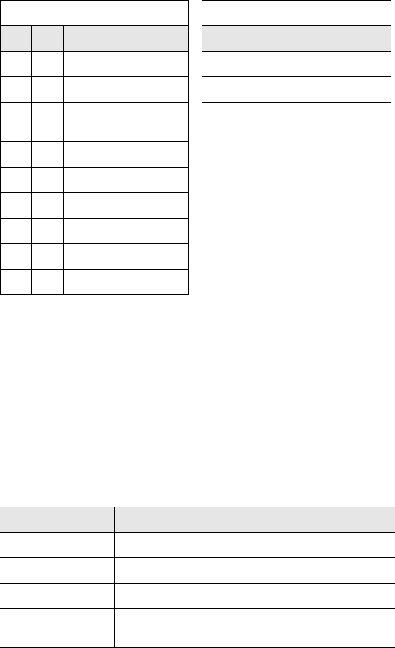
Table 5-2: ABx Error Codes
Error Code Description
05H Block Read has failed
06H Block Write has failed
08H Search Tag Operation failed
21H Syntax error
0DH Command Read error. You will receive a Command Read
error if you send another command while the LRP75 is in
Continuous Read mode.
0FH Command Read SN and Data error. You will receive a
Command Read error if you send another command while
the LRP75 is in Continuous Read SN and Data mode.

Standard RFID Interface
20 LRP75 Long Range Passive Reader/Writer
5.4.1 ABx Standard Error Format
ABxS error codes are returned in the LSB of the second register
passed to the PLC. The format of the error response is shown below.
A Block Write fail error message would appear as: AAFF 0006
FFFFH.
5.5 Command Descriptions
The LRP75 supports two forms of ABx RFID commands; ABx
Standard and ABx Fast.
The ABx Standard is a binary protocol, word (2-byte oriented) so that
the syntax table reports the Most Significant Byte (MSB) and the Least
Significant Byte (LSB). In serial transmission the MSB is transmitted
first. User data is passed only in the LSB meaning that one word is
required for each byte of user data.
ABX Fast is byte oriented and uses both MSB and LSB to pass user
data. This is more efficient as each work passes two bytes of user
data.
5.6 ABx Standard Commands
5.6.1 Command 4 (04 Hex): Tag Fill
DESCRIPTION
Fill an RFID tag with a one byte value over multiple contiguous
addresses.
DISCUSSION
This command is commonly used to clear an RFID tag's memory. It
writes a one byte value repetitively across a specified range of tag
addresses.
The fill function requires one data value byte, a starting address, and a
fill length. It will then proceed to fill the tag with the data value byte,
starting at the specified start address for the specified number of
consecutive bytes. When Fill Length is set to 0, the LRP75 will write fill
Error Response from the LRP75
MSB LSB
AAH FFH
00H Error Code
FFH FFH
Standard RFID Interface
LRP75 Long Range Passive Reader/Writer 21
data from the start address to the end of the tag's memory. The
timeout value is given in 1 msec increments and can have a value of
1EH to FFFEH (65,534 ms). When the timeout is set to 0, the LRP75
will return a syntax error.
EXAMPLE
Writes 'A' (41H) to the tag starting at address 0005H for the following
next consecutive 10 bytes. A timeout of 2 seconds (07D0H = 2000 x 1
msec increments) is set for the completion of the configuration.
Field Description
Header AAH
Command Command number in Hex
Start Address The tag address where the fill will start
Fill Length The number of tag addresses to be filled
Timeout Timeout value given in 1 ms units (1EH - FFFEH)
Data Value Byte The byte to be used as fill
Message
Terminator
FFFFH
Command from the Host Response from the LRP75
MSB LSB Remarks MSB LSB Remarks
AAH 04H Perform Command 4 AAH 04H Command Echo
00H 05H Start Address = 0005H FFH FFH Message Terminator
00H 0AH Fill Length = 10 bytes
(000AH)
07H D0H Timeout value
00H 41H Fill byte
FFH FFH Message Terminator

Standard RFID Interface
22 LRP75 Long Range Passive Reader/Writer
5.6.2 Command 5 (05 Hex): Block Read
DESCRIPTION
Read a block of data from an RFID tag.
DISCUSSION
The RF Block Read command is used to read segments of data from
contiguous areas of tag memory. It is capable of transferring the entire
read/write address range of the tag to the host with one command.
The timeout value is given in 1 msec increments and can have a value
of 1EH to FFFEH. A timeout of 0 will return a syntax error.
The data read from the tag is returned in the LSB of the register, and
the MSB is always 00H.
Field Description
Header AAH
Command Command number in hex
Start Address The tag address where the read will start
Read Length The number of tag addresses to be read
Timeout Timeout value given in 1 ms units (1EH - FFFEH)
Message
Term inato r
FFFFH

Standard RFID Interface
LRP75 Long Range Passive Reader/Writer 23
EXAMPLE
Reads 8 bytes of data from the tag starting at address 01H. A timeout
of 2 seconds (07D0H = 2000 x 1 msec increments) is set for the
completion of the Block Read.
Command from the Host Response from the LRP75
MSB LSB Remarks MSB LSB Remarks
AAH 05H Perform Command 5 AAH 05H Command Echo
00H 01H Start Address = 0001H 00H 52H Read Data 1 = 52H
00H 08H Read Block Length = 8 bytes
(0008H) 00H 46H Read Data 2 = 46H
07H D0H Timeout value 00H 49H Read Data 3 = 49H
FFH FFH Message Terminator 00H 44H Read Data 4 = 44H
00H 20H Read Data 5 = 20H
00H 54H Read Data 6 = 54H
00H 61H Read Data 7 = 61H
00H 67H Read Data 8 = 67H
FFH FFH Message Terminator

Standard RFID Interface
24 LRP75 Long Range Passive Reader/Writer
5.6.3 Command 6 (06 Hex): Block Write
DESCRIPTION
Write a block of data to an RFID tag.
DISCUSSION
The RF Port Block Write command is used to write segments of data
to contiguous areas of tag memory. It is capable of transferring up to
48 bytes of data. The timeout value is given in 1 msec increments and
can have a value of 1EH to FFFEH. A timeout of 0 will return a syntax
error.
The data to be written to the tag is contained in the LSB of the register,
and the MSB is always 00H.
Field Description
Header AAH
Command Command number in hex
Start Address The tag address where the write will start
Write Length The number of tag addresses to be written
Timeout Timeout value given in 1 ms units (1EH - FFFEH)
Write Data The data to be written
Message
Term inato r
FFFFH
Standard RFID Interface
LRP75 Long Range Passive Reader/Writer 25
EXAMPLE
Writes 4 bytes of data to the tag starting at address 0001H. A timeout
of 2 seconds (07D0H = 2000 x 1 msec increments) is set for the
completion of the Block Write.
5.6.4 Command 7 (07H): Read Tag Serial Number
DESCRIPTION
This command retrieves the 8-byte tag serial number.
DISCUSSION
Each LRP tag has a unique serial number. This number can not be
changed and is not part of the 48 available data bytes. The tag serial
number will be returned in the LSB only with the MSB as 00H. The
timeout value is given in 1 msec increments and can have a value of
1EH to FFFEH.
Command from the Host Response from the LRP75
MSB LSB Remarks MSB LSB Remarks
AAH 06H Perform Command 6 AAH 06H Command Echo
00H 01H Start Address = 0001H FFH FFH Message Terminator
00H 04H Write Length= 4 bytes
(0004H)
07H D0H Timeout value
00H 41H Write Data 1 = 41H
00H 46H Write Data 2 = 46H
00H 49H Write Data 3 = 49H
00H 44H Write Data 4 = 44H
FFH FFH Message Terminator
Field Description
Header AAH
Command Command number in hex
Timeout Timeout value given in 1 ms units (1EH - FFFEH)
Message
Terminator
FFFFH
Standard RFID Interface
26 LRP75 Long Range Passive Reader/Writer
EXAMPLE
This example reads the 8-byte serial number. In this example the
serial number is 1E6E3DC200000001 in hexadecimal. A timeout of 2
seconds (07D0H = 2000 x 1 msec increments) is set for the
completion of the Read Tag Serial Number.
5.6.5 Command 8 (08 Hex): Tag Search
DESCRIPTION
Check to see if there is an RFID tag in the LRP75 field.
DISCUSSION
This command will activate the reader/write to "look" for a tag in the
RF field. If the LRP75 finds a tag it will return a command echo to the
host. The timeout value is given in 1 msec increments and can have a
value of 1EH to FFFEH. If no tag is present it will return an error
message.
Command from the Host Response from the LRP75
MSB LSB Remarks MSB LSB Remarks
AAH 07H Perform Command 7 AAH 07H Command Echo
07H D0H Timeout value 00H 1EH Tag ID byte 1
FFH FFH Message Terminator 00H 6EH Tag ID byte 2
00H 3DH Tag ID byte 3
00H C2H Tag ID byte 4
00H 00H Tag ID byte 5
00H 00H Tag ID byte 6
00H 00H Tag ID byte 7
00H 01H Tag ID byte 8
FFH FFH Message Terminator
Field Description
Header AAH
Command Command number in hex
Timeout Timeout value given in 1 ms units (1EH - FFFEH)
Message
Term inato r
FFFFH

Standard RFID Interface
LRP75 Long Range Passive Reader/Writer 27
EXAMPLE
Checks for an RFID tag in the RF field. A timeout of 2 seconds
(07D0H = 2000 x 1 msec increments) is set for the completion of the
Tag Search.
5.6.6 Command D (0D Hex): Start/Stop Continuous
Block Read
DESCRIPTION
When in Continuous Block Read mode, the LRP75 sends block read
commands continuously to any tag in range of the antenna. The value
in the length field controls the command (start/stop).
DISCUSSION
When a tag enters the field of the antenna, the LRP75 reads the
specified data and passes it to the host. The LRP75 continues to read
the tag, but will not send the same data to the host until the tag has
been out of the antenna’s range for a specified time period. This
period is called the Delay Between Identical Reads. It prevents
redundant data transmission when the LRP75 is in Continuous Block
Read mode. The Delay Between Identical Reads can have an integral
value in seconds between 0 and 60. A value of 0 makes the LRP75
continuously read any tag in the RF field and send the data to the
host.
The LRP75 remains in Continuous Block Read mode until it receives
a new continuous read command with a zero read length. To stop
Continuous Block Read Mode, issue the Start/Stop Continuous Read
command with a read length of zero (0).
If the LRP75 receives any other command from the host while
performing continuous read, an error (0DH) will be sent to the host.
Command from the Host Response from the LRP75
MSB LSB Remarks MSB LSB Remarks
AAH 08H Perform Command 8 AAH 08H Command Echo
07H D0H Timeout value FFH FFH Message Terminator
FFH FFH Message Terminator
Standard RFID Interface
28 LRP75 Long Range Passive Reader/Writer
NOTE:Other commands will NOT be performed when the LRP75 is
performing continuous read.
EXAMPLE
The following example reads 8 bytes of data from a tag at address
05H, with a delay between identical reads of 2. After a tag is read, it
must remain out of the RF field for at least 2 seconds before it will be
read again. The LRP75 will send a response confirming its in
Continuous Block Read mode.
Field Description
Header AAH
Command Command number in hex
Start Address The tag address where the read will start
Read Length The number of tag addresses to be read. A 0 length
stops continuous mode.
Delay Between
Identical Reads
Time period that the tag must be out of reading
range before the LRP75 will send the same data to
the host.
Message
Term inato r
FFFFH
Command from the Host Response from the LRP75
MSB LSB Remarks MSB LSB Remarks
AAH 0DH Perform Command D AAH 0DH Command Echo
00H 05H Start Address FFH FFH Message Terminator
00H 08H Read Length
00H 02H Delay Between Identical
Reads
FFH FFH Message Terminator

Standard RFID Interface
LRP75 Long Range Passive Reader/Writer 29
When a tag arrives, the LRP will send the requested tag data.
Command from the Host
MSB LSB Remarks
AAH 0DH Command Echo
00H 44H Data byte 1
00H 20H Data byte 2
00H 54H Data byte 3
00H 61H Data byte 4
00H 67H Data byte 5
00H 20H Data byte 6
00H 20H Data byte 7
00H 20H Data byte 8
FFH FFH Message Terminator
Standard RFID Interface
30 LRP75 Long Range Passive Reader/Writer
5.6.7 Command E (0EH) Read SN and Data
DESCRIPTION
Command E reads the tag's Serial Number along with tag data, and
sends it back to the host in one response packet. If the length is zero
(0), then only the Serial Number is returned to the host.
EXAMPLE
The below example reads the SN and one data byte at tag address
five (05H), with a two second timeout. The tag data is 20H.
Field Description
Header AAH
Command Command number in hex
Start Address The tag address where the read will start
Read Length The number of tag addresses to be read
Timeout Timeout value given in 1 ms units (1EH - FFFEH)
Message
Term inato r
FFFFH
Command from the Host Response from the LRP75
MSB LSB Remarks MSB LSB Remarks
AAH 0EH Perform Command E AAH 0EH Command Echo
00H 05H Start Address 00H 7DH Serial Number byte 1
00H 01H Read Length 00H EFH Serial Number byte 2
07H D0H 2 Second Timeout 00H 4CH Serial Number byte 3
FFH FFH Message Terminator 00H 00H Serial Number byte 4
00H 00H Serial Number byte 5
00H 00H Serial Number byte 6
00H 00H Serial Number byte 7
00H 01H Serial Number byte 8
00H 20H Data byte
FFH FFH Message Terminator

Standard RFID Interface
LRP75 Long Range Passive Reader/Writer 31
5.6.8 Command F (0FH) Start/Stop Continuous Read
SN and Data
DESCRIPTION
When in Continuous Block Read SN and Data mode, the LRP75
sends Read SN and Data commands continuously to any tag in range
of the antenna. The value in the Start/Stop field controls the command
(start/stop).
DISCUSSION
When a tag enters the field of the antenna, the LRP75 reads the SN
and data, and then passes them to the host. The LRP75 continues to
read the tag, but will not send the same data to the host until the tag
has been out of the antenna’s range for a specified time period. This
period is called the Delay Between Identical Reads. It prevents
redundant data transmission when the LRP75 is in Continuous Read
SN and Data mode. The Delay Between Identical Reads can have an
integral value in seconds between 0 and 60. A value of 0 makes the
LRP75 continuously read any tag in the RF field and send the data to
the host.
The Start/Stop Continuous Read SN and Data command has a field to
start and stop continuous reading. To stop Continuous Read SN and
Data, issue the command with zero (0) in the start/stop byte.
If the LRP75 receives any other command from the host while in
continuous mode, an error (0FH) will be sent to the host.
NOTE:Other commands will NOT be performed when the LRP75 is in
continuous mode.
Field Description
Header AAH
Command Command number in hex
Start Address The tag address where the read will start
Read Length The number of tag addresses to be read
Delay Between
Identical Reads
Time period that the tag must be out of reading
range before the LRP75 will send the same data to
the host.
Start/Stop 01H starts continuous mode and 00H stops it.
Message
Terminator
FFFFH
Standard RFID Interface
32 LRP75 Long Range Passive Reader/Writer
EXAMPLE
This example will wait until a tag is in range and then reads 2 bytes of
data from the tag starting at address 05H.
When a tag comes into range of the LRP75, it will perform the read
and return the data as follows.
Command from the Host Response from the LRP75
MSB LSB Remarks MSB LSB Remarks
AAH 0FH Perform Command F AAH 0FH Command Echo
00H 05H Start Address = 0005H FFH FFH Message Terminator
00H 02H Read Length = 2 bytes
00H 0AH 10 second delay between
identical reads
00H 01H Start Continuous mode
FFH FFH Message Terminator
Response from the LRP75
MSB LSB Remarks
AAH 0FH Command Echo
00H 52H Serial Number 1 = 52H
00H 46H Serial Number 2 = 46H
00H 49H Serial Number 3 = 49H
00H 44H Serial Number 4 = 44H
00H 50H Serial Number 5 = 50H
00H 51H Serial Number 6 = 51H
00H 53H Serial Number 7 = 53H
00H 01H Serial Number 8 = 01H
00H 55H Data Byte 1 = 55H
00H 56H Data Byte 2 = 56H
FFH FFH Message Terminator

Standard RFID Interface
LRP75 Long Range Passive Reader/Writer 33
5.7 ABx Fast Commands
The difference from the standard ABx are:
• The command/response packet contains the packet size
• You can include a checksum in the command
• The headers and terminator are ASCII characters
Since ABx Fast is a binary protocol, the Xon/Xoff handshake cannot
be used.
5.7.1 ABx Command Packet Structure
The command protocol is based on the following minimal packet
structure. The data field and the checksum may not be present
depending on the command type and your checksum setting.
Following a successful operation, the LRP75 will respond with the
following. The data field and the checksum may not be present
depending on the command and checksum setting.
Field Number
of Bytes Description
Header 2 <STX><STX> (02H, 02H)
Command
Size
2 Packet length in bytes excluding the header,
command size, checksum and terminator
bytes.
Command 1 Command Code (XXH)
(Data) variable Command parameters/data
Checksum 1 Optional Checksum
Terminator 1 <ETX> (03H)
Field Number
of Bytes Description
Header 2 <STX><STX> (02H, 02H)
Response
Size
2 Packet length in bytes excluding the header,
command size, checksum and terminator
bytes.
Command
Echo
1 Command Echo (XXH)
(Data) variable Response data
Checksum 1 Optional Checksum
Terminator 1 <ETX> (03H)

Standard RFID Interface
34 LRP75 Long Range Passive Reader/Writer
If the LRP75 encounters a fault, it will respond with the following:
• The Header and Terminator are always STX-STX and ETX
respectively.
• All other bytes are interpreted as binary data (0 - 255 dec).
• Fields with two bytes are sent most significant byte (MSB) first.
The sequence for each command is given with the response format in
the following section.
Command/Response Size
The ABx Fast requires that the length of the packet be included in the
command. All parameters and data between the Command/Response
Size and the Checksum or Terminator bytes must be accounted for in
the command/response size word. This includes all command codes
and parameters such as field definitions for Block Read/Writes. The
command/response size will be the same with, or without, a
checksum.
Checksum
The optional checksum must be enabled from the operating mode
menu to be available. The checksum is calculated by adding all the
byte values in the packet (less the values in the header, checksum if
present, and terminator), discarding byte overflow and subtracting the
byte sum from FFH. Thus, when the packet length through the
checksum are added as byte values, the sum will be FFH.
Field Number
of Bytes Description
Header 2 <STX><STX> (02H, 02H)
Response
Size
2 Packet length in bytes excluding the header,
command size, checksum and terminator
bytes.
Error Flag 1 FFH
Error Code 1 Hex error code
Checksum 1 Optional Checksum
Terminator 1 <ETX> (03H)
Standard RFID Interface
LRP75 Long Range Passive Reader/Writer 35
EXAMPLE
The following is a typical command using a checksum.
The summed values begin with the Command Size and end with the
timeout value. That sum, less overflow, is subtracted from FFH for the
checksum value.
Thus: 00 + 03 + 01 +07 + D0 = DB
FF - DB = 24H
5.7.2 Command 4 (04 Hex): Tag Fill
DESCRIPTION
Fill an RFID tag with a one byte value over multiple contiguous
addresses.
DISCUSSION
This command is commonly used to clear an RFID tag's memory. It
writes a one byte value repetitively across a specified range of tag
addresses.
The fill function requires one data value byte, a starting address, and a
fill length. It will then proceed to fill the tag with the data value byte,
starting at the specified start address for the specified number of
consecutive bytes.
Command from Host
Field Contents
Header
<STX><STX> 02H
02H
Command Size 00H
03H
Command Code 01H
Timeout 07H
D0H
Checksum 24H
Terminator <ETX> 03H
Sum these values to
calculate the checksum

Standard RFID Interface
36 LRP75 Long Range Passive Reader/Writer
The timeout value is given in 1 msec increments and can have a value
of 1EH to FFFEH (65,534 ms). When the timeout is set to 0, the
LRP75 will return a syntax error.
Field Description
Header <STX><STX>
Command Size Packet length in bytes, excluding the header,
command size, checksum and terminator bytes.
Command 04H
Start Address 2-byte value for the tag address where the fill will
start
Fill Length 2-byte value for the number of tag addresses to be
filled
Timeout 2-byte timeout value given in 1 ms units (1EH -
FFFEH)
Data Value Byte The byte to be used as fill
Checksum optional checksum
Message
Term inato r
FFFFH
Standard RFID Interface
LRP75 Long Range Passive Reader/Writer 37
A response to a successful command will follow this form.
EXAMPLE
Writes 'A' (41H) to the tag starting at address 0005H for the following
next consecutive 10 bytes. A timeout of 2 seconds (07D0H = 2000 x 1
msec increments) is set for the completion of the configuration.
Field Description
Header <STX><STX>
Response Size Packet length in bytes, excluding the header,
command size, checksum and terminator bytes.
Command Echo 04H
Checksum optional checksum
Message
Terminator
FFFFH
Command from the Host Response from the LRP75
Field Contents Field Contents
Header 02H Header 02H
02H 02H
Command Size 00H Response Size 00H
08H 01H
Command Code 04H Command Echo 04H
Start Address 00H Terminator <ETX> 03H
05H
Fill Length 00H
0AH
Timeout, 2 seconds 07H
D0H
Fill byte 41H
Terminator <ETX> 03H

Standard RFID Interface
38 LRP75 Long Range Passive Reader/Writer
5.7.3 Command 5 (05 Hex): Block Read
DESCRIPTION
Read a block of data from an RFID tag.
DISCUSSION
The RF Block Read command is used to read segments of data from
contiguous areas of tag memory. It is capable of transferring the entire
read/write address range of the tag to the host with one command.
The timeout value is given in 1 msec increments and can have a value
of 1EH to FFFEH. A timeout of 0 will return a syntax error.
The data read from the tag is returned in the LSB of the register, and
the MSB is always 00H.
Field Description
Header <STX><STX>
Command Size Packet length in bytes, excluding the header,
command size, checksum and terminator bytes.
Command 05H
Start Address 2-byte value for the tag address where the read will
start.
Read Length 2-byte value for the number of tag addresses to be
read.
Timeout 2-byte timeout value given in 1 ms units (1EH -
FFFEH)
Checksum optional checksum
Message
Term inato r
FFFFH

Standard RFID Interface
LRP75 Long Range Passive Reader/Writer 39
EXAMPLE
Reads 4 bytes of data from the tag starting at address 01H. A timeout
of 2 seconds (07D0H = 2000 x 1 msec increments) is set for the
completion of the Block Read.
Command from the Host Response from the LRP75
Field Contents Field Contents
Header 02H Header 02H
02H 02H
Command Size 00H Response Size 00H
07H 05H
Command Code 05H Command Echo 05H
Start Address 00H Data from address
0001H 05H
01H Data from address
0002H AAH
Read Length 00H Data from address
0003H E7H
04H Data from address
0004H 0AH
Timeout, 2 seconds 07H Terminator <ETX> 03H
D0H
Terminator <ETX> 03H

Standard RFID Interface
40 LRP75 Long Range Passive Reader/Writer
5.7.4 Command 6 (06 Hex): Block Write
DESCRIPTION
Write a block of data to an RFID tag.
DISCUSSION
The RF Port Block Write command is used to write segments of data
to contiguous areas of tag memory. It is capable of transferring up to
48 bytes of data. The timeout value is given in 1 msec increments and
can have a value of 1EH to FFFEH. A timeout of 0 will return a syntax
error.
The data to be written to the tag is contained in the LSB of the register,
and the MSB is always 00H.
Field Description
Header <STX><STX>
Command Size Packet length in bytes, excluding the header,
command size, checksum and terminator bytes.
Command 06H
Start Address 2-byte value for the tag address where the write will
start.
Write Length 2-byte value for the number of tag addresses to be
written to.
Timeout 2-byte timeout value given in 1 ms units (1EH -
FFFEH)
Data Data bytes to be written
Checksum optional checksum
Te rm in ato r <E TX >

Standard RFID Interface
LRP75 Long Range Passive Reader/Writer 41
EXAMPLE
Writes 4 bytes of data to the tag starting at address 0001H. A timeout
of 2 seconds (07D0H = 2000 x 1 msec increments) is set for the
completion of the Block Write.
Command from the Host Response from the LRP75
Field Contents Field Contents
Header 02H Header 02H
02H 02H
Command Size 00H Response Size 00H
0BH 01H
Command Code 06H Command Echo 06H
Start Address 00H Terminator <ETX> 03H
01H
Write Length 00H
04H
Timeout, 2 seconds 07H
D0H
Data to write to
address 0001H 52H
Data to write to
address 0002H 46H
Data to write to
address 0003H 49H
Data to write to
address 0004H 44H
Terminator <ETX> 03H

Standard RFID Interface
42 LRP75 Long Range Passive Reader/Writer
5.7.5 Command 7 (07H): Read Tag Serial Number
DESCRIPTION
This command retrieves the 8-byte tag serial number.
DISCUSSION
Each LRP tag has an unique serial number. This number can not be
changed and is not part of the 48 available data bytes. The tag serial
number will be return in the LSB only with the MSB as 00H. The
timeout value is given in 1 msec increments and can have a value of
1EH to FFFEH.
Field Description
Header <STX><STX>
Command Size Packet length in bytes, excluding the header,
command size, checksum and terminator bytes.
Command 07H
Timeout 2-byte timeout value given in 1 ms units (1EH -
FFFEH)
Checksum optional checksum
Message
Term inato r
FFFFH
Standard RFID Interface
LRP75 Long Range Passive Reader/Writer 43
EXAMPLE
This example reads the 8-byte serial number. In this example the
serial number is 1E6E3DC200000001 in hexadecimal. A timeout of 2
seconds (07D0H = 2000 x 1 msec increments) is set for the
completion of the Read Tag Serial Number.
Command from the Host Response from the LRP75
Field Contents Field Contents
Header 02H Header 02H
02H 02H
Command Size 00H Response Size 00H
03H 09H
Command Code 07H Command Echo 07H
Timeout, 2 seconds 07H SN Byte 1 1EH
D0H SN Byte 2 6EH
Terminator <ETX> 03H SN Byte 3 3DH
SN Byte 4 C2H
SN Byte 5 00H
SN Byte 6 00H
SN Byte 7 00H
SN Byte 8 01H
Terminator <ETX> 03H

Standard RFID Interface
44 LRP75 Long Range Passive Reader/Writer
5.7.6 Command 8 (08 Hex): Tag Search
DESCRIPTION
Check to see if there is an RFID tag in the LRP75 field.
DISCUSSION
This command will activate the reader/write to "look" for a tag in the
RF field. If the LRP75 finds a tag it will return a command echo to the
host. The timeout value is given in 1 msec increments and can have a
value of 1EH to FFFEH. If no tag is present it will return an error
message.
Field Description
Header <STX><STX>
Command Size Packet length in bytes, excluding the header,
command size, checksum and terminator bytes.
Command 08H
Timeout 2-byte timeout value given in 1 ms units (1EH -
FFFEH)
Checksum optional checksum
Message
Term inato r
FFFFH

Standard RFID Interface
LRP75 Long Range Passive Reader/Writer 45
EXAMPLE
Checks for an RFID tag in the RF field. A timeout of 2 seconds
(07D0H = 2000 x 1 msec increments) is set for the completion of the
Tag Search.
5.7.7 Command D (0D Hex): Start/Stop Continuous
Block Read
DESCRIPTION
When in Continuous Block Read mode, the LRP75 sends block read
commands continuously to any tag in range of the antenna. The value
in the length field controls the command (start/stop).
DISCUSSION
When a tag enters the field of the antenna, the LRP75 reads the
specified data and passes it to the host. The LRP75 continues to read
the tag, but will not send the same data to the host until the tag has
been out of the antenna’s range for a specified time period. This
period is called the Delay Between Identical Reads. It prevents
redundant data transmission when the LRP75 is in Continuous Block
Read mode. The Delay Between Identical Reads can have an integral
value in seconds between 0 and 60. A value of 0 makes the LRP75
continuously read any tag in the RF field and send the data to the
host.
Command from the Host Response from the LRP75
Field Contents Field Contents
Header 02H Header 02H
02H 02H
Command Size 00H Response Size 00H
03H 01H
Command Code 08H Command Echo 08H
Timeout, 2 seconds 07H Terminator <ETX> 03H
D0H
Terminator <ETX> 03H

Standard RFID Interface
46 LRP75 Long Range Passive Reader/Writer
The LRP75 remains in Continuous Block Read mode until it receives
a new continuous read command with a zero read length. To stop
Continuous Block Read Mode, issue the Start/Stop Continuous Read
command with a read length of zero (0).
If the LRP75 receives any other command from the host while
performing continuous read, an error (0DH) will be sent to the host.
NOTE:Other commands will NOT be performed when the LRP75 is
performing continuous read.
Field Description
Header <STX><STX>
Command Size Packet length in bytes, excluding the header,
command size, checksum and terminator bytes.
Command 0DH
Start Address 2-byte value for the tag address where the read will
start
Read Length 2-byte value for the length of the read
Delay Between
Identical Reads
1-byte delay (0-60 seconds)
Checksum optional checksum
Message
Term inato r
FFFFH

Standard RFID Interface
LRP75 Long Range Passive Reader/Writer 47
EXAMPLE
The following example reads 4 bytes of data from a tag at address
05H, with a delay between identical reads of 2. After a tag is read, it
must remain out of the RF field for at least 2 seconds before it will be
read again. The LRP75 will send a response confirming its in
Continuous Block Read mode.
Command from the Host Response from the LRP75
Field Contents Field Contents
Header 02H Header 02H
02H 02H
Command Size 00H Response Size 00H
06H 01H
Command Code 0DH Command Echo 0DH
Start Address 00H Terminator <ETX> 03H
05H
Read Length 00H
04H
Delay Between
Identical Decodes 02H
Terminator <ETX> 03H

Standard RFID Interface
48 LRP75 Long Range Passive Reader/Writer
When a tag arrives, the LRP will send the requested tag data.
Response from the LRP75
Field Contents
Header 02H
02H
Response Size 00H
05H
Command Echo 0DH
Data from address
0005H 05H
Data from address
0006H AAH
Data from address
0007H E7H
Data from address
0008H 0AH
Terminator <ETX> 03H

Standard RFID Interface
LRP75 Long Range Passive Reader/Writer 49
5.7.8 Command E (0EH) Read SN and Data
DESCRIPTION
Command E reads the tag's Serial Number along with tag data, and
sends it back to the host in one response packet. If the length is zero
(0), then only the Serial Number is returned to the host.
Field Description
Header <STX><STX>
Command Size Packet length in bytes, excluding the header,
command size, checksum and terminator bytes.
Command 0EH
Start Address 2-byte value for the tag address where the read will
start
Read Length 2-byte value for the length of the read
Timeout 2-byte timeout value given in 1 ms units (1EH -
FFFEH)
Checksum optional checksum
Message
Terminator
FFFFH

Standard RFID Interface
50 LRP75 Long Range Passive Reader/Writer
EXAMPLE
The below example reads the SN and one data byte at tag address
five (05H), with a two second timeout. The tag data is 20H.
Command from the Host Response from the LRP75
Field Contents Field Contents
Header 02H Header 02H
02H 02H
Command Size 00H Response Size 00H
05H 0AH
Command Code 0EH Command Echo 0EH
Start Address 00H SN Byte 1 1EH
05H SN Byte 2 6EH
Read Length 00H SN Byte 3 3DH
01H SN Byte 4 C2H
Timeout 07H SN Byte 5 00H
D0H SN Byte 6 00H
Terminator <ETX> 03H SN Byte 7 00H
SN Byte 8 01H
Data Byte 20H
Terminator <ETX> 03H
Standard RFID Interface
LRP75 Long Range Passive Reader/Writer 51
5.7.9 Command F (0FH) Start/Stop Continuous Read
SN and Data
DESCRIPTION
When in Continuous Block Read Serial Number and Data mode, the
LRP75 sends Read SN and Data commands continuously to any tag
in range of the antenna. The value in the Start/Stop field controls the
command (start/stop).
DISCUSSION
When a tag enters the field of the antenna, the LRP75 reads the SN
and data, and then passes them to the host. The LRP75 continues to
read the tag, but will not send the same data to the host until the tag
has been out of the antenna’s range for a specified time period. This
period is called the Delay Between Identical Reads. It prevents
redundant data transmission when the LRP75 is in Continuous Read
SN and Data mode. The Delay Between Identical Reads can have an
integral value in seconds between 0 and 60. A value of 0 makes the
LRP75 continuously read any tag in the RF field and send the data to
the host.
The Start/Stop Continuous Read SN and Data command has a field to
start and stop continuous reading. To stop Continuous Read SN and
Data, issue the command with zero (0) in the start/stop byte.

Standard RFID Interface
52 LRP75 Long Range Passive Reader/Writer
If the LRP75 receives any other command from the host while in
continuous mode, an error (0FH) will be sent to the host.
NOTE:Other commands will NOT be performed when the LRP75 is in
continuous mode.
Field Description
Header <STX><STX>
Command Size Packet length in bytes, excluding the header,
command size, checksum and terminator bytes.
Command 0FH
Start Address 2-byte value for the tag address where the read will
start
Read Length 2-byte value for the length of the read
Delay Between
Identical Reads
1-byte delay (0-60 seconds)
Start/Stop Byte 01H starts continuous mode and 00H stops it.
Checksum optional checksum
Message
Term inato r
FFFFH

Standard RFID Interface
LRP75 Long Range Passive Reader/Writer 53
EXAMPLE
This example will wait until a tag is in range and then reads 2 bytes of
data from the tag starting at address 05H.
Command from the Host Response from the LRP75
Field Contents Field Contents
Header 02H Header 02H
02H 02H
Command Size 00H Response Size 00H
07H 01H
Command Code 0FH Command Echo 0FH
Start Address 00H Terminator <ETX> 03H
05H
Read Length 00H
02H
Delay Between
Identical Decodes 02H
Start/Stop Byte 01H
Terminator <ETX> 03H

Standard RFID Interface
54 LRP75 Long Range Passive Reader/Writer
When a tag comes into range of the LRP75, it will perform the read
and return the data as follows.
Response from the LRP75
Field Contents
Header 02H
02H
Response Size 00H
0BH
Command Echo 0EH
SN Byte 1 1EH
SN Byte 2 6EH
SN Byte 3 3DH
SN Byte 4 C2H
SN Byte 5 00H
SN Byte 6 00H
SN Byte 7 00H
SN Byte 8 01H
Data Byte 1 20H
Data Byte 2 20H
Terminator <ETX> 03H

LRP75 Long Range Passive Reader/Writer 55
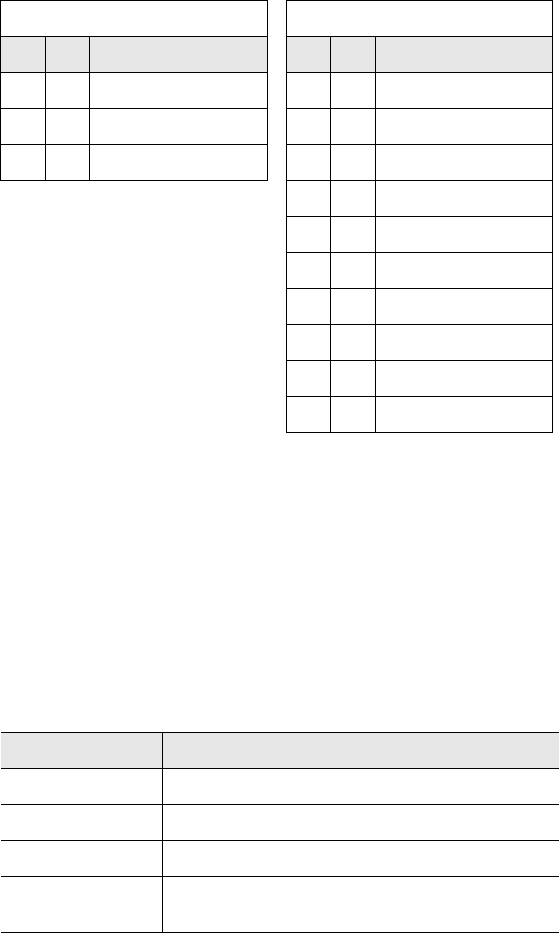
Appendix A
Technical Specifications
A.1 Electrical Characteristics
Power Voltage 24 Vdc +/- 10%
Consumption 250 mA max.
A.2 Physical Characteristics
Dimensions (L x W x H) 4.125 x 2.125 x 1.5"
Enclosure ABS
A.3 Environmental
Protection Class NEMA 2
A.4 Communication Characteristics
RF Interface LRP-Series Passive RFID System
COM1 RS232/RS422
Technical Specifications
56 LRP75 Long Range Passive Reader/Writer
This page left blank intentionally.
LRP75 Long Range Passive Reader/Writer 57
Appendix B
LRP75 Beta Connections
Early models of the LRP75 have two terminal blocks for power and
serial communication. If you are wiring a LRP75 Beta unit, use the
pinouts given in this appendix.
B.1 Internal Junction Blocks
The LRP75 is connected to external power and communications
cabling through two internal terminal blocks. The power and serial
communication junction blocks accept AWG 22-14 wires.
Figure B-1. Internal junction block
B.2 Power Connections
Connection to power is through the internal J2 terminal block.
Table 5-3: J2 Power Connection
Terminal Description
1+24 Vdc
2 Power Ground

LRP75 Beta Connections
58 LRP75 Long Range Passive Reader/Writer
B.3 Serial Connections
The Prod Nm can be wired to communication with the host either
through an RS232 or RS422 interface. Connection to the serial
interface is through the J1 terminal shown in Figure B-1 on page -57.
Connect the signal ground to terminal 2 on the J2 power terminal.
Table 5-4 gives the pinouts for the J1 terminal block.
For more information on power requirements and serial
communication options, see Chapter 3, Power and Electrical
Interface.
Table 5-4: J1 Serial Communications Pinouts
Terminal Function
1 Reserved, no connection
2 Reserved, no connection
3 RS232 RX (from host DB9, pin 3)
4 RS232 TX (from host DB9, pin 2)
5RS422 RX +
6RS422 TX +
7RS422 RX -
8RS422 TX -
J2, pin 2 Connect the signal ground to pin 2 of terminal block J2

LRP75 Long Range Passive Reader/Writer 59
Appendix C
Models and Accessories
Model Description
LRP75 Long Range Passive Reader/Writer for LRP-Series tags
LRP Series
RFID Tags Description
LRP125 Long-range passive read/write tag, 25 mm dia. round, 48 bytes
memory
LRP125HT Long-range passive read/write tag, 25 mm dia. round, 48 bytes
memory, survives 240° temperatures
LRP250 Long-range passive read/write tag, 50 mm square, 48 bytes
memory
LRP250HT Long-range passive read/write tag, 50 mm square, 48 bytes
memory, survives 240° temperatures
LRP125HT-FLX Long-range passive read/write tag, 25 mm dia. round, 48 bytes
memory, survives 240° temperatures, flexible with high
temperature adhesive backing
LRP250HT-FLX Long-range passive read/write tag, 50 mm dia. round, 48 bytes
memory, survives 240° temperatures, flexible with high
temperature adhesive backing
LRP-L5555 Long-range passive read/write tag, 55 mm square, 48 bytes
memory, thermal transfer with adhesive backing
LRP-L2666 Long-range passive read/write tag, 26 x 66 mm, 48 bytes
memory, thermal transfer with adhesive backing
LRP-L4982 Long-range passive read/write tag, 49 x 82 mm, 48 bytes
memory, thermal transfer with adhesive backing
LRP-P125 Long-range passive read/write tag, 25 mm square, 48 bytes
memory, PCB
LRP-P3858 Long-range passive read/write tag, 38 x 58 mm, 48 bytes
memory, PCB
LRP-P5050 Long-range passive read/write tag, 50 mm square, 48 bytes
memory, PCB
Models and Accessories
60 LRP75 Long Range Passive Reader/Writer
This page left blank intentionally.

LRP75 Long Range Passive Reader/Writer 61
Appendix D
ASCII Chart
Decimal Hex Character Decimal Hex Character
000 00 NUL 032 20 (SPACE)
001 01 SOH 033 21 !
002 02 STX 034 22 "
003 03 ETX 035 23 #
004 04 EOT 036 24 $
005 05 ENQ 037 25 %
006 06 ACK 038 26 &
007 07 BEL 039 27 ’
008 08 BS 040 28 (
009 09 HT 041 29 )
010 0A LF 042 2A *
011 0B VT 043 2B +
012 0C FF 044 2C ,
013 0D CR 045 2D -
014 0E SO 046 2E .
015 0F SI 047 2F /
016 10 DLE 048 30 0
017 11 DC1 049 31 1
018 12 DC2 050 32 2
019 13 DC3 051 33 3
020 14 DC4 052 34 4
021 15 NAK 053 35 5
022 16 SYN 054 36 6
023 17 ETB 055 37 7
024 18 CAN 056 38 8
025 19 EM 057 39 9
026 1A SUB 058 3A :
027 1B ESC 059 3B ;
028 1C FS 060 3C <
029 1D GS 061 3D =
030 1E RS 062 3E >
031 1F US 063 3F ?

ASCII Chart
62 LRP75 Long Range Passive Reader/Writer
064 40 @ 096 60 ‘
065 41 A 097 61 a
066 42 B 098 62 b
067 43 C 099 63 c
068 44 D 100 64 d
069 45 E 101 65 e
070 46 F 102 66 f
071 47 G 103 67 g
072 48 H 104 68 h
073 49 I 105 69 i
074 4A J 106 6A j
075 4B K 107 6B k
076 4C L 108 6C l
077 4D M 109 6D m
0784E N 1106E n
079 4F O 111 6F o
08050 P 11270 p
08151 Q 11371 q
08252 R 11472 r
08353 S 11573 s
08454 T 11674 t
08555 U 11775 u
08656 V 11876 v
08757 W 11977 w
088 58 X 120 78 x
089 59 Y 121 79 y
090 5A Z 122 7A z
091 5B [ 123 7B {
092 5C \ 124 7C |
093 5D ] 125 7D }
094 5E ^ 126 7E ~
095 5F _ 127 7F DEL
Decimal Hex Character Decimal Hex Character