Baron Weather KHDD-1000C WEATHER RADAR SYSTEM User Manual Sigmet RVP8 Users Guide
Baron Services Inc WEATHER RADAR SYSTEM Sigmet RVP8 Users Guide
Contents
- 1. Sigmet RVP8 Users Guide
- 2. Page 143 of the Sigmet RVP8 Manual
Sigmet RVP8 Users Guide
141
SIGMET RVP8 USERS GUIDE

142
1. Introduction and Specifications
The RVP8 Lineage
SIGMET Inc. has a 20-year history of supplying innovative, high-quality signal processing products
to the weather radar community. The history of SIGMET products reads like a history of weather
radar signal processing:
Much of the proven, tested, documented software from the highly-successful RVP7
(written in C) is ported directly to the new RVP8 architecture. This allows SIGMET to
reduce time-to-market and produce a high-quality, reliable system from day one. However,
the new RVP8 is not simply a re-hosting of the RVP7. The RVP8 provides new
capabilities for weather radar systems that, until now, were not available outside of the
research community.
Advanced Digital Transmitter Option
For example, the RVP8 takes the next logical step after a digital receiver- a digitally synthesized IF
transmit waveform output that is mixed with the STALO to provide the RF waveform to the
transmitter amplifier (e.g., Klystron or TWT). The optional RVP8/Tx card opens the door for
advanced processing algorithms such as pulse compression, frequency agility and phase agility that
were not possible before, or done in more costly ways.
Units
Year Model Sold Major Technical Milestones
1981 FFT 10 First commercial FFT-based Doppler signal processor for weather
radar applications. Featured Simultaneous Doppler and intensity
processing.
1985 RVP5 161 First single-board low-cost Doppler signal processor. First com-
mercial application of dual PRF velocity unfolding algorithm.
1986 PP02 12 First high-performance commercial pulse pair processor with
18.75-m bin spacing and 1024 bins.
1992 RVP6 150 First commercial floating-point DSP-chip based processor. First
commercial processor to implement selectable pulse pair, FFT or
random phase 2nd trip echo filtering.
1996 RVP7 >200 First commercial processor to implement fully digital IF processing
for weather radar.
2003 RVP8
First digital receiver/signal processor to be implemented using an
open hardware and software architecture on standard PC hardware
under the Linux operating system. Public API’s are provided so that
customers may implement their own custom processing algorithms.
143
Open Hardware and Software Design
Compared to previous processors that were built around proprietary DSP chips, perhaps the most
innovative aspect of the RVP8 is that it is implemented on standard PC hardware and software that
can be purchased from a wide variety of sources. The Intel Pentium/PCI approach promises continued
improvement in processor speed, bus bandwidth and the availability of low–cost compatible hardware
and peripherals. The performance of an entry level RVP8 (currently dual
2.4 GHz Pentium processors) is 6 times faster than the fastest RVP7 ever produced (with two
RVP7/AUX boards).
Aside from the open hardware approach, the RVP8 has an open software approach as well. The
RVP8 runs in the context of the Linux operating system. The code is structured and public API’s are
provided so that research customers can modify/replace existing SIGMET algorithms, or write their
own software from scratch using the RVP8 software structure as a foundation on which to build.
The advantage of the open hardware and software PCI approach is reduced cost and the ability for
customers to maintain, upgrade and expand the processor in the future by purchasing standard, low
cost PC components from local sources.
SoftPlane High–Speed I/O Interconnect
There are potentially many different I/O signals emanating from the backpanel of the RVP8. Most of
these conform to well-known electrical and protocol standards (VGA, SCSI, 10–BaseT, RS-232
Serial, PS/2 Keyboard, etc.), and can be driven by standard commercial boards that are available
from multiple vendors. However, there are other interface signals such as triggers and clocks that
require careful timing. These precise signals cannot tolerate the PCI bus latency. For signals that
have medium–speed requirements (~1 microsec latency) for which the PCI bus is inappropriate; and
others that require a high–speed (~ 1 ns latency) connection that can only be
achieved with a dedicated wire, the RVP8 Softplane᪽᪽provides the solution᪽
Physically, the Softplane᪽ is a 16-wire digital “daisy-chain” bus that plugs into the tops of the
RVP8/Rx, RVP8/Tx, and I/O boards. The wires connect to the FPGA chips on each card, and the
function of each wire is assigned at run–time based on the connectivity needs of the overall system.
The Softplane᪽ allocates a dedicated wire to carry each high-speed signal; but groups of medium-
speed signals are multiplexed onto single wires in order to conserve resources. Even though there are
only 16 wires available, the Softplane is able to carry several high-speed signals and hundreds of
medium–speed signals, as long as the total bandwidth does not exceed about 600MBits/sec.
The Softplane᪽ I/O is configured at run–time based on a file description rather than custom wiring
such as wirewrap. Neither the PCI backplane nor the physical Softplane᪽ are customized in any
way. Since there is no custom wiring, a failed board can be replaced with a generic off–the–shelf
spare, and that spare will automatically resume whatever functions had been assigned to the original
board. Similarly, if the chassis itself were to fail, then simply plugging the boards into another
generic chassis would restore complete operation. Cards and chassis can be swapped between
systems without needing to worry about custom wiring.
144
Standard LAN Interconnection for Data Transfer or Parallel Processing
For communication with the outside world, the RVP8 supports as standard a 10/100/1000 Base T
Ethernet. For most applications, the 100 BaseT Ethernet is used to transfer moment results (Z, T, V,
W) to the applications host computer (e.g., a product generator). However, the gigabit Ethernet is
sufficiently fast to allow UDP broadcast of the I and Q values for the purpose of archiving and/or
parallel processing. In other words, a completely separate signal processor can ingest and process the
I and Q values generated by the RVP8.
145
1.1 System Configuration Concepts
The hardware building blocks of an RVP8 system are actually quite few in number:
᪽RVP8/IFD᪽ IF Digitizer Unit-This is a separate sealed unit usually mounted in the
receiver cabinet. The primary input to the IFD is the received IF signal. In addition, the IFD has
channels to sample the transmit pulse and to take in an external clock to phase lock the A/D
conversion with the transmit pulse (not used for magnetron systems).
᪽RVP8/Rx᪽ Card-A PCI card mounted in the chassis. It connects to the IFD by a
CAT-5E cable which can be up to 25m long. In addition, there are two BNC trigger outputs
and four RS-422 programmable I/O signals.
᪽I/O-62᪽ Card and Connector Panel-These handle all of the various I/O associated
with a radar signal processor, such as triggers, antenna angles, polarization switch controls,
pulse width control, etc. The Connector Panel is mounted on either the front or rear of the
equipment rack and a cable (supplied) connects the panel to the I/O-62.
᪽Optional RVP8/Tx᪽ card-This supplies two IF output signals with programmable
frequency, phase and amplitude modulation. In the simplest case it might merely supply the
COHO which is mixed with the STALO to generate the transmit RF for Klystron or TWT
systems. More interesting applications include pulse compression and frequency agility
scanning. This card is not necessary for magnetron systems.
᪽PC Chassis and Processor with various peripherals- a robust 4U rack mount unit with
a dual-Xeon mother board, diagnostic front panel display, disk (mechanical or flash), CDRW,
keyboard, mouse and optional monitor for local diagnostic work. Redundant power supplies are
used, and there are redundant fans as well.
This modular hardware approach allows the various components to be mixed and matched to support
applications ranging from a simple magnetron system to an advanced dual polarization system with
pulse compression. Typically SIGMET supplies turn-key systems, although some OEM customers
who produce many systems purchase individual components and integrate them by themselves. This
allows OEM customers to put their own custom “stamp” on the processor and even their own custom
software if they so choose.
For the turnkey systems provided by SIGMET, the basic chassis is a 6U rack mount unit as
described above. A 2U chassis can be provided for applications for which space is limited. A very
low cost approach is to use a desk side PC, but this is not recommended for applications that
require long periods of unattended operation.
To illustrate various RVP8 configurations, some typical examples are shown below. For clarity, all
the examples show the single–board computer approach. A mother board approach is equivalent.
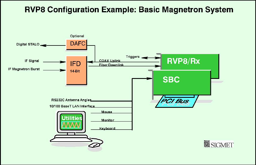
Example 1: Basic Magnetron System
The building blocks required to construct the basic system are:
146
IFD- IF Digitizer installed in the radar receiver cabinet. This can be located up to 100
meters from the RVP8 main chassis (fiber optic connection). The DAFC (Digital AFC) is an
option to interface to a digitally controlled STALO. Like the RVP7, the RVP8 provides full
AFC with burst pulse auto-tracking.
RVP8/Rx- The digital receiver collects digitized samples from the IFD and does the
processing to obtain I/Q. It also provides two trigger connections configurable for input or
output.
SBC Card- Single Board Computer with dual SMP processors (PC) running Linux.
The figure above shows a basic magnetron system constructed with an IFD, and two PCI cards. A
standard RS-232 serial input (included with the SBC) is used for obtaining the antenna angles and
the output/input trigger is provided directly from the Rx card. This system has 5 times the processing
power of the fastest version of the previous generation processor (RVP7/Main board plus 2
RVP7/AUX boards) so that it is capable of performing DFT processing in 2048 rangebins with
advanced algorithms such as random phase 2nd trip echo filtering and recovery.
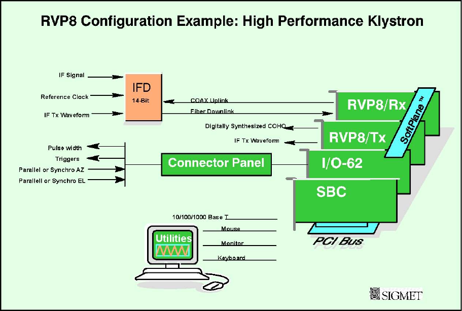
Example 2: Klystron System with Digital Tx
In this case, the IFD can receive a master clock from the radar system (e.g., the COHO). This
ensures that the entire system is phase locked. As compared to the previous example there are two
additional cards shown in this example:
147
RVP8/Tx- The digital transmitter card provides the digital Tx waveform. A second output
can be used to provide a COHO in the event that the RVP8 is used to provide the system
master clock. In any case, the IF transit waveform and the A/D sampling are phase locked.
SIGMET I/O-62 card for additional triggers, parallel, synchro or encoder AZ and EL angle
inputs, pulse width control, spot blanking control output, etc. These signals are brought in via
the connector panel.
The figure shows the SIGMET SoftPlane᪽ which carries time-critical I/O such as clock and
trigger information which is not appropriate for the PCI bus. These signals are limited to the
cards provided by SIGMET, i.e., the SoftPlane᪽ is not connected to any of the standard
commercial cards.
148
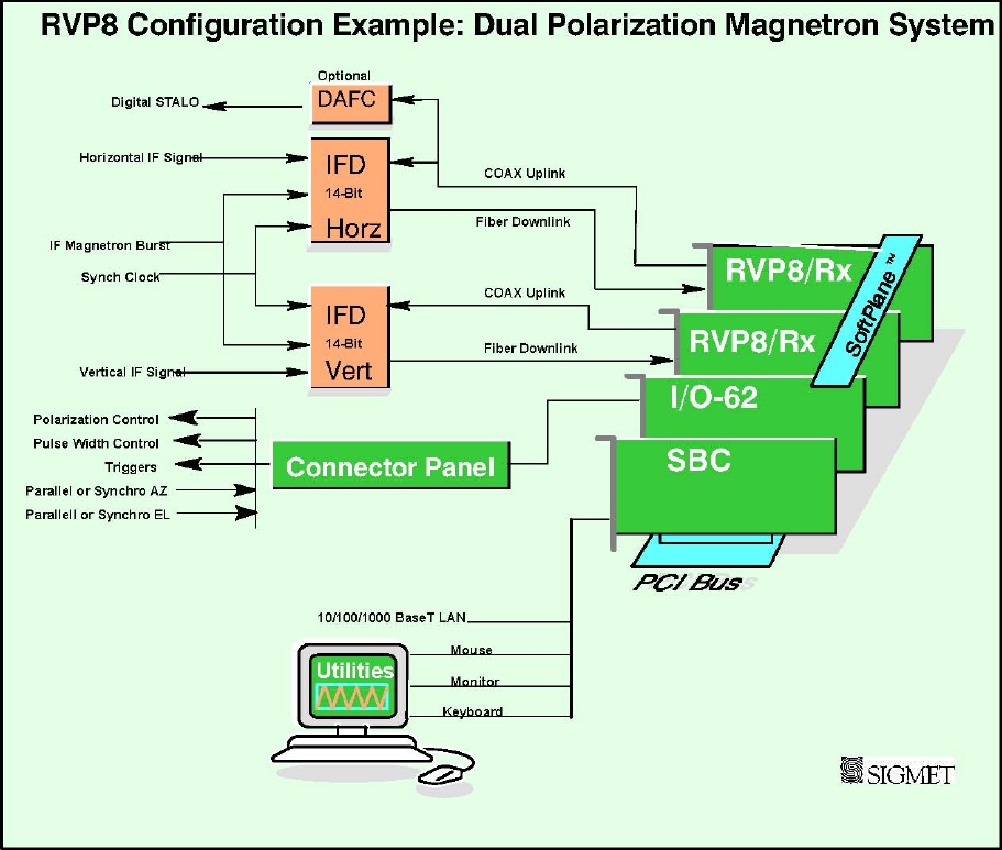
Example 3: Dual Polarization Magnetron System
In this system 2 IFD’s and two RVP8/Rx cards are used for the horizontal and vertical channels of a
dual-channel receiver. The legacy RVP7 technique of using a single IFD and two IF frequencies for
the horizontal and vertical channels (e.g., 24 and 30 MHz) is also supported by the RVP8. In the case
of either dual or single IFD’s, there is a synch clock provided by either the STALO reference
frequency (e.g., 10 MHz) or by the RVP8 itself.
The RVP8 supports calculation of the complete covariance matrix for dual pol, including ZDR,
PHIDP (KDP), RHOHV, LDR, etc. Which of these variables is available depends on whether the
system is a single–channel switching system (alternate H and V), a STAR system (simultaneous
transmit and receive) or a dual channel switching system (co and cross receivers). Note that for the
special case of a single channel switching system, only one IFD is required.
149
COTS Accessories
Aside from the basic PCI cards required for the radar application, there are additional cards that can
be installed to meet different customer requirements, e.g.,
10/100–BaseT Ethernet card for additional network I/O (e.g., a backup network).
RS-232/RS-422 serial cards for serial angles, remote TTY control, etc.
Sound card to synthesize audio waveforms for wind profiler applications.
GPS card for time synch.
IEEE 488 GPIB card for control of test equipment.
The bottom line is that the PCI open hardware approach provides unparalleled hardware
flexibility. In addition, the availability of compatible low-cost replacement or upgrade parts is
assured for years into the future.
150
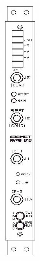
1.1.1 IFD IF Digitizer
The IFD 14-bit IF digitizer is a totally sealed unit for optimum low-noise
performance. The use of digital components within the IFD is minimized
and the unit is carefully grounded and shielded to make the cleanest possible
digital capture of the input IF signal. Because of this, the IFD achieves the
theoretical minimum noise level for the A/D convertors.
There are 4 inputs to the IFD:
IF video signal.
A secondary IF video signal, used for dual polarization or very wide
dynamic range applications.
IF Burst Pulse for magnetron or IF COHO for Klystron.
Optional reference clock for system synchronization. For a Klystron
system, the COHO can be input. Magnetron systems do not require this
signal. This clock can even come from the RVP8/Tx card itself.
All of these inputs are on SMA connectors. The IF signal input is made
immediately after the STALO mixing/sideband filtering step of the receiver
where a traditional log receiver would normally be installed. The required
signal level for both the IF signal and burst is +6.5 dBm for the strongest
expected input signal. A fixed attenuator or IF amplifier may be used to
adjust the signal level to be in this range.
Digitizing is performed for both the IF signal and burst/COHO channels at
approximately 72 MHz to 14-bits. This provides 92 to 105 dB of dynamic
range (depending on pulse width) without using complex AGC, dual A/D
ranging or down mixing to a lower IF frequency.
All communication to the main RVP8 chassis goes over a special CAT5E
type cable. The major volume of data is the raw time series samples sent
down to the RVP8 Rx card. Coming back up is trigger timing and AFC
information to the IFD.
The RVP8 provides comprehensive AFC support for tuning the STALO of a magnetron system.
Alternatively, the magnetron itself can be tuned by a motorized tuning circuit controlled by the
RVP8. Both analog (+–10V) and digital tuning (with optional DAFC to 24 bits) are supported.

151
1.1.2 Digital Receiver PCI Card (RVP8/Rx)
The RVP8/Rx card receives the digitized IF samples from the IFD via the fiber optic
link. The advantage of this design is that the receiver electronics (LNA, RF mixer, IF
preamp, and IFD) can be located as far as 100–meters away from the RVP8 main
chassis. This makes it possible to choose optimum locations for both the IFD and the
RVP8, e.g., the IFD could be mounted on the antenna itself, and the processor box in a
nearby equipment room.
The RVP8/Rx is 100% compatible with the 14-bit RVP7/IFD, but it also includes
hooks for future IFD’s operating at higher sampling clock rates. Two additional BNC
connectors are included on the board’s faceplate. These can be used for trigger input,
programmable trigger output, or a simple LOG analog ascope waveform.
A remarkable amount of computing power is resident on the receiver board, in the
form of an FIR filter array that can execute 6.9 billion multiply/accumulate cycles per
second. These chips serve as the first stage of processing of the raw IF data samples.
Their job is to perform the down–conversion, bandpass, and deconvolution steps that
are required to produce (I,Q) time series. The time series data are then transferred over
the PCI bus to the SBC for final processing.
The FIR filter array can buffer as much as 80 microsec of 36MHz IF samples, and then compute a
pair of 2880–point dot products on those data every 0.83 microsec. This could be used to produce
over-sampled (I,Q) time series having a range resolution of 125–meters and a bandwidth as narrow
as 30Khz. The same computation could also yield independent 125–meter time series data from an
80 microsec compressed pulse whose transmit bandwidth was approximately 1MHz.
Finer range resolutions are also possible, down to a minimum of 25–meters. A special feature of the
RVP8/Rx is that the bin spacing of the (I,Q) data can be set to any desired value between 25 and
2000 meters. Range bins are placed accurately to within +2.2 meters of any selected grid, which does
not have to be an integer multiple of the sampling clock. However, when an integer multiple (N x
8.333–meters) is selected, the error in bin placement effectively drops to zero.
Dual polarization radars that are capable of simultaneous reception for both horizontal and
vertical channels can be interfaced to the RVP8 using a separate RVP8/Rx and IFD for each
channel. Note that the multiplexed dual IF approach used for the RVP7 with a single IFD can also
be used.
One of the primary advantages of the digital receiver approach is that wide linear dynamic range can
be achieved without the need for complex AGC circuits that require both phase and amplitude
calibration.
152
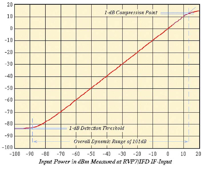
Calibration Plot for RVP8/IFD
The figure above shows a calibration plot for a 14-bit IFD with the digital filter matched to a 2
microsecond pulse. The performance in this case is >100 dB dynamic range. The RVP8
performs several real time signal corrections to the I/Q samples from the Rx, including:
Amplitude Correction- A running average of the transmit pulse power in the magnetron burst
channel is computed in real-time by the RVP8/Rx. The individual received I/Q samples are
corrected for pulse–to–pulse deviations from this average. This can substantially improve the
“phase stability” of a magnetron system to improve the clutter cancelation performance to near
Klystron levels.
Phase Correction- The phase of the transmit waveform is measured for each pulse (either the
burst pulse for magnetron systems or the Tx Waveform for coherent systems). The I/Q values are
adjusted for the actual measured phase. The coherency achievable is better than 0.1 degrees by this
technique.
Large Signal Linearization- When an IF signal saturates, there is still considerable information in
the signal since only the peaks are clipped. The proprietary large signal linearization algorithm used
in the RVP8 provides an extra 3 to 4 dB of dynamic range by accounting for the effects of
saturation.
The RVP8/Rx card provides the same comprehensive configuration and test utilities as the RVP7,
with the difference that no external host computer is required to run the utilities. These utilities
can be run either locally or remotely, over the network! Some examples are shown below:
153
᪽᪽᪽᪽᪽᪽᪽᪽᪽᪽᪽᪽᪽᪽᪽᪽᪽᪽᪽
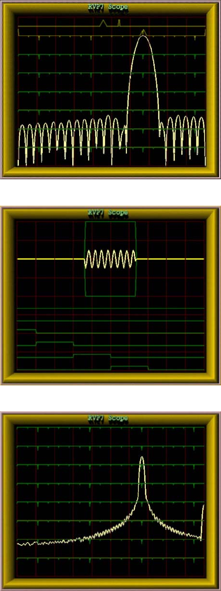
᪽᪽᪽᪽᪽᪽᪽᪽᪽᪽᪽᪽᪽ The built–in filter design tool makes it easy fo
r
anyone to design the optimal IF filter to match
each pulse width and application. Simply specify
the impulse response and pass band and the filte
r
appears. The user interface makes it easy to wid-
en/narrow the filter with simple keyboard com-
mands. There is even a command to automatically
search for an optimal filter.
This display can also show the actual spectrum o
f
the transmit burst pulse for quality control an
d
comparison with the filter.
᪽᪽᪽᪽᪽᪽᪽᪽᪽᪽᪽᪽᪽᪽᪽᪽
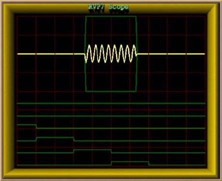
᪽᪽᪽᪽᪽᪽᪽᪽᪽᪽ The quality assessment of the transmit burs
t
p
ulse and its precise alignment at range zero are
easy to do, either manually using this tool and/o
r
automatically using the burst pulse auto-trac
k
feature. This performs a 2D search in both time
and frequency space if a valid burst pulse is no
t
detected. The automatic tracking makes the AFC
robust to start–up temperature changes and pulse
width changes that can effect the magnetron
frequency.
AFC alignment/check is now much easier since
it can be done manually from a central
maintenance site or fully automatically.
᪽᪽᪽᪽᪽᪽᪽᪽᪽᪽᪽᪽᪽᪽᪽᪽᪽᪽᪽᪽᪽᪽᪽
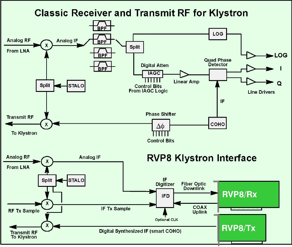
᪽᪽᪽᪽᪽᪽᪽᪽᪽᪽᪽᪽᪽᪽᪽ The RVP8 provides plots of the IF signal versus
range as well as spectrum analysis of the signal
as shown in this example.
In the past, these types of displays and tools re-
quired that a highly-skilled engineer transpor
t
some very expensive test equipment to the rada
r
site. Now, detailed analysis and configuration
can all be done from a central maintenance facil-
ity via the network. For a multi-radar networ
k
this results in substantial savings in equipment,
time and labor.

154
1.1.3 Mother Board or Single-Board Computer (SBC)
The dual-CPU Pentium mother board or single-board computer (SBC) acts as the hos
t
to the Linux operating system and provides all of the compute resources for processing
the I/Q values that are generated by the RVP8/Rx card. Standard keyboard, mouse and
monitor connections are on the Rx backpanel, along with a 10/100/1000 BaseT Ether-
net port. The system does not require that a keyboard, mouse or monitor be connecte
d
which is typically the case at an unattended site. An SBC example is shown on the left.
Motherboards and SBC’s are available from many vendors, at various speeds Typical-
ly the SBC is equipped with 128 MB RAM. The RVP8 chassis has a front bay fo
r
either a >20 GB hard disk or a Flash Disk. The Flash Disk approach is well suited to
applications where high–reliability is important. CDRW is also provided for software
maintenance. Note that the latest versions of the RVP8 software and documentation can
always be down-loaded from SIGMET’s web site for FREE.
The SBC also plays host for SIGMET’s RVP8 Utilities which provide test, configura-
tion, control and monitoring software as well as built–in on-line documentation.
1.1.4 Digital Transmitter PCI Card (RVP8/Tx)
Many of the exciting new meteorological applications for the RVP8 are made possible
by its ability to function as a digital radar transmitter. The RVP8/Tx PCI card synthe-
sizes an output waveform that is centered at at the radar’s intermediate frequency. This
signal is filtered using analog components, then up–converted to RF, and finally am-
plified for transmission. The actual transmitter can be a solid state or vacuum tube de-
vice. The RVP8 can even correct for waveform distortion by adaptively “pre–distort-
ing” the transmit waveform, based on the measured transmit burst sample.
The Tx card has a BNC output for the IF Tx waveform. In addition, there is a secon
d
output for an auxiliary signal or clock, or for a clock input. At the bottom of the card is
a 9–pin connector for arbitrary I/O (e.g., TTL, RS422, additional clock).
The RVP8 digital transmitter finds a place within the overall radar system that exactly
complements the digital receiver. The receiver samples an IF waveform that has been
down–converted from RF, and the transmitter synthesizes an IF waveform for up–con-
version to RF. The beauty of this approach is that the RVP8 now has complete control
over both halves of the radar, making possible a whole new realm of matched Tx/Rx
processing algorithms. Some examples are given below:
᪽Phase Modulation- Some radar processing algorithms rely on modulating the phase of the
transmitter from pulse to pulse. This is traditionally done using an external IF phase modulator that
is operated by digital control lines. While this usually works well, it requires additional hardware
and cabling within the radar cabinet, and the phase/amplitude characteristics may not
155
be precise or repeatable. In contrast, the RVP8/Tx can perform precise phase modulation to any
desired angle, without requiring the use of external phase shifting hardware.
Pulse Compression-There is increasing demand for siting radars in urban areas that also
happen to have strict regulations on transmit emissions. Often the peak transmit power is
limited in these areas; so the job for the weather radar is to somehow illuminate its targets
using longer pulses at lower power. The problem, of course, is that a simple long pulse
lacks the ability (bandwidth) to discern targets in range. The remedy is to increase the Tx
bandwidth by modulating the overall pulse envelope, so that a reasonable range resolution
is restored. The exceptional fidelity of the RVP8/Tx waveform can accomplish this
without introducing any of the spurious modulation components that often occur when
external phase modulation hardware is used.
Frequency Agility- This has been well studied within the research community, but has
remained out of the reach of practical weather radars. The RVP8/Tx changes all of this,
because frequency agility is as simple as changing the center frequency of the synthesized
IF waveform. Many new Range/Doppler unfolding algorithms become possible when
multiple transmit frequencies can coexist. Frequency agility can also be combined with
pulse compression to remedy the blind spot at close ranges while the long pulse is being
transmitted.
COHO synthesis- The RVP8/Tx output waveform can be programmed to be a simple
CW sine wave. It can be synthesized at any desired frequency and amplitude, and its
phase is locked to the other system clocks. If you need a dedicated oscillator at some
random frequency in the IF band, this is a simple way to get it.
156
1.1.5 I/O-62 PCI Card and I/O Panel
The SIGMET I/O-62 is a short format PCI card that provides extensive I/O capabilities
for the RVP8. A typical installation would have one I/O-62 and an RVP8 Connecto
r
Panel shown above. The Softplane᪽ is used to interconnect the I/O 62 with other SIG-
MET PCI cards. Note that the identical card is used in the SIGMET RCP8 radar/antenna
control processor which in general does not use the Softplane᪽ connection. The I/O-62
has a single 62-position, high-density “D” connector. This is attached to the RVP8
Connector Panel (typically mounted on the front or back of the rack which holds the
RVP8). A standard 1:1 cable connects the remote panel to the I/O-62 card in the RCP8
chassis. The standard connector panel provided by SIGMET meets the needs of mos
t
radar sites.
The best part is that the I/O-62 is configurable in software, i.e., there is no need to open
the chassis to configure jumpers or switches. This means that when a spare board is
added, there is no need to perform hardware configuration or custom wiring.
The physical I/O lines are summarized in the system specifications section.
E
SD Protection Features
Since the I/O lines are connected to the radar system, there is a potential for lightning or othe
r
ESD type damage. This is addressed aggressively by the I/O-62 in two ways:
᪽Every wire is protected by a Tranzorb᪽ diode which transitions from an open to a full
clamp between ᪽27 to ᪽35 VDC. Additionally, the Connector Panel uses Tranzorb᪽diodes
on every I/O line for double protection.
᪽High-voltage tolerant front-end receivers/drivers are used. All components connected to
the external pins can tolerate up to ᪽40V. For example, the TTL and wide range inputs use
protectors that normally look like 100 Ohm resistors, but open at high voltage.
157
R
un Time FPGA Con
f
i
g
uration
The SIGMET I/O-62 card is built around a 100K–Gate FPGA which, in addition to driving the I/O
signals on the 62-position connector, also coordinates the PCI and Softplane᪽ traffic. These chips
are SRAM–based, meaning that they are configured at run time. This allows the FPGA code to be
automatically upgraded during each RVP8 code release without needing to physically reprogram any
parts.
The board’s basic I/O services use up only 40% of the complete FPGA. The leftover space makes it
possible to add smart processing right on the I/O-62 board to handle custom needs. For example the
16–bit floating–point (I,Q) data in the previous example could be reformatted into a 32–bit fixed–
point stream. Other examples include generating custom serial formats, data debouncing, and signal
transition detection. In general, I/O functions that would either be tedious or inappropriate for the
host computer SBC can likely be moved onto the I/O-62 card itself.
158
1.2 Comparison of Analog vs Digital Radar Receivers
1.2.1 What is a Digital IF Receiver?
A digital IF receiver accepts the analog IF signal (typically 30 MHz), processes it and outputs a
stream of wide dynamic range digital “I” and “Q” values. These quantities are then processed to
obtain the moment data (e.g., Z, V, W or polarization variables). Additionally, the digital receiver
can accept the transmit pulse “burst sample” for the purpose of measuring the frequency, phase and
power of the transmit pulse. The functions that can be performed by the digital receiver are:
IF band pass filtering
“I” and “Q” calculation over wide dynamic range
Phase measurement and correction of transmitted pulse for magnetron systems – from
burst sample
Amplitude measurement and correction of transmitted pulse – from burst sample
Frequency measurement for AFC output – from burst sample
The digital approach replaces virtually all of the traditional IF receiver components with flexible
software-controlled modules that can be easily adapted to function for a wide variety of radars and
operational requirements.
The digital receiver approach made a very rapid entry into the weather radar market. Up until the
about 1997 weather radars were not supplied with digital receivers. Today in 2003 nearly all new
weather radars and weather radar upgrades use the digital receiver approach. Much of this rapid
change is attributed to the previous generation RVP7 which is the most widely sold weather radar
signal processor of all time.
The number one advantage of a digital receiver is that it achieves a wide linear dynamic range (e.g.,
>95dB depending on pulse width) without having to use AGC circuits which are complex to build,
calibrate and maintain. However, there are other advantages as well:
Lower initial cost by eliminating virtually all IF receiver components.
Lower life cycle cost do to reduced maintenance.
Selectable IF frequency.
Software controlled AFC with automatic alignment.
Programmable band pass filter
Dual or multiple IF multiplexing
Improved remote monitoring down to the IF level.
The following sections compare the digital receiver approach to the analog receiver approach.
This illustrates the advantages of the digital approach and what functions are performed by a
digital receiver.
159
1.2.2 Magnetron Receiver Example
A typical analog receiver for a magnetron system is shown in the top portion of Figure 1–1. The
received RF signal from the LNA is first mixed with the STALO (RF–IF) and the resulting IF signal
is applied to one of several bandpass filters that match the width of the transmitted pulse. The filter
selection is usually done with relays. The narrow band waveform is then split. Half is applied to a
LOG amplifier having a dynamic range of 80–100dB, from which a calibrated measurement of signal
power can be obtained. The LOG amplifier is required because it is almost impossible to build a
linear amplifier with the required dynamic range. However, phase distortion within the LOG
amplifier renders it unsuitable for making Doppler measurements; hence, a separate linear channel is
still required.
The linear amplifier is fed from the other half of the bandpass filter split. It may be preceded by a
gain control circuit (IAGC) which adjusts the instantaneous signal strength to fall within the limited
dynamic range of the linear amplifier. The amplitude and phase characteristics of the IAGC
attenuator must be calibrated so that the “I” and “Q” samples may be corrected during processing.
The IF output from the linear amplifier is applied to a pair of mixers that produce “I” and “Q”. The
mixer pair must have very symmetric phase and gain characteristics, and each must be supplied with
an accurate 0-degree and 90-degree version of the Coherent Local Oscillator (COHO). The later is
usually obtained by sampling a portion of the transmitted pulse, and then phase locking an oscillator
(COHO) that continues to “ring” afterward. Phase locked COHO’s of this sort can be very
troublesome – they often fail to lock properly, drift with age, and fail to maintain coherence over the
full unambiguous range.
The transmit burst that locks the COHO is also used by the Automatic Frequency Control (AFC)
loop. The AFC relies on an FM discriminator and low pass filter to produce a correction voltage that
maintains a constant difference between the magnetron frequency and the reference STALO
frequency. The AFC circuit is often troublesome to set and maintain. Also, since it operates
continuously, small phase errors are continually being introduced within each coherent processing
interval.
In contrast, the RVP8 digital receiver is shown in to lower portion of Figure 1–1. The only old parts
that still remain are the microwave STALO oscillator, and the mixer that produces the transmit burst.
The burst pulse and the analog IF waveform are cabled directly into the IFD on SMA coax cables.
Likewise, the AFC control voltage is also a simple direct connection either with analog tuning (+–
10V from IFD) or digital control via the optional DAFC interface. These cables constitute the
complete interface to the radar’s internal signals; no other connections are required within the
receiver cabinet.

160
RVP8 User’s Manual
October 2006 Introduction and Specifications
Figure 1–1: Analog vs Digital Receiver for Magnetron Systems
161
1.2.3 Klystron or TWT Receiver and Transmit RF Example
A typical analog receiver for a klystron system is shown in the top portion of Figure 1–2. The
arrangement of components is similar to the magnetron case, except that the COHO operates at a
fixed phase and frequency, a phase shifter is included for 2nd trip echo filtering and there is no AFC
feedback required. The phase stability of a Klystron system is better than a magnetron, but the system
is still constrained by limited linear dynamic range, IAGC inaccuracy, quad phase detector
asymmetries, phase shifter inaccuracies, etc.
The RVP8/Tx card now plays the role of a programmable COHO. The digitally synthesized transmit
waveform can be phase, frequency and amplitude modulated (no separate phase shifter is required)
and even produce multiple simultaneous transmit frequencies. These capabilities are used to support
advanced algorithms, e.g., range/velocity ambiguity resolution or pulse compression for low power
TWT systems.
Figure 1–2: Analog vs Digital Receiver for Klystron Systems
162
1.3 RVP8 IF Signal Processing
1.3.1 IFD Data Capture and Timing
The RVP8 design concept is to perform very little signal processing within the IFD digitizer
module itself. This is to minimize the presence of digital components that might interfere with the
clean capture of the IF signals.
The digitized IF and burst pulse samples are multiplexed onto the fiber channel link which provides
the digital data to the RVP8/Main board at approximately 540-MBits/sec. The 14-bit samples are
encoded for transmission over a fiber channel link. This optical link allows the IFD to be as far as
100 meters away from the RVP8/Main board and provides an added degree of noise immunity and
isolation.
The uplink input from the RVP8/Main board provides the timing for multiplexing the burst pulse
sample with the IF signal. In addition, it is used to set the AFC DAC or digital output level, and to
perform self tests.
The sample clock oscillator in the IFD is selected to be very stable. The sample clock serves a
similar function to the COHO on a traditional Klystron system, i.e., it is the master time keeper.
Because of this the IFD sample clock is used to phase lock the entire RVP8, i.e., the Rx, Tx, IO-62
boards and the SoftPlane are all phase locked to the IFD sample clock. Designers have two choices
for factory configuration of the IFD sample clock:
A fixed crystal frequency selected to achieve a desired range resolution. The standard
range resolution corresponds to 25 m increments.
A very narrow band VCXO (50 ppm) selected to lock to an input reference signal from
the radar, and provide a desired range resolution. SIGMET stocks VCXO’s for 25 m range
resolution increments for reference inputs of 10, 20, 30 and 60 MHz. Custom frequency VCXO’s
are available on request. Examples of external reference signal sources are an external COHO,
external STALO reference or perhaps even a GPS clock).
163
1.3.2 Burst Pulse Analysis for Amplitude/Frequency/Phase
The burst pulse analysis provides the amplitude,
frequency and phase of the transmitted pulse.
The phase measurement is analogous to the
COHO locking that is performed by a traditional
magnetron radar. The difference is that the phase
is known in the digital technique, so that range
dealiasing using the phase modulation
techniques is possible. Amplitude measurement
(not performed by traditional radars) can provide
enhanced performance by allowing the “I” and
“Q” values to be corrected for variations in the
both the average and the pulse-to-pulse
transmitted power. In addition, a warning is
issued if the burst pulse amplitude falls below a
threshold value.
The burst pulse data stream is first analyzed by an adaptive algorithm to locate the burst pulse power
envelope (e.g. 0.8 ᪽sec). The algorithm first does a coarse search for the burst pulse in the
time/frequency domain (by scanning the AFC) and then does a fine search in both time and
frequency, to assure that the burst is centered at “range 0” and is at the required IF value. The power-
weighted phase of the burst pulse and the total burst pulse power is then computed. The power
weighted average phase is used to make the digital phase correction. Phase jitter for magnetron
systems with good quality modulator and STALO is better than 0.5 degrees RMS, as measured on
actual nearby clutter targets. For Klystron systems, the phase locking is better than
0.1 degree RMS.
The burst pulse frequency is also analyzed to calculate the frequency error from the nominal IF
frequency. For magnetron systems, the error is filtered with a selectable time constant which is
typically set to several minutes to compensate for slow drift of the magnetron. The digital frequency
error is sent via the uplink to the IFD in the receiver cabinet where a DAC converts it into an analog
output to the magnetron STALO. Optionally, a DAFC unit can be Teed off the uplink cable to
interface to Klystron systems do not require the AFC.
164
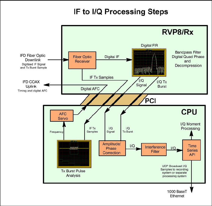
1.3.3 Rx Board and CPU IF to I/Q Processing
Figure 1–3: IF to I/Q Processing Steps
The RVP8/Rx board performs the initial processing of the IF digital data stream and outputs “I” an
d
“Q” data values to the host computer via the PCI bus. In addition, the frequency, phase an
d
amplitude of the burst pulse are measured. The functions performed by the processor are:
Reception of the digital serial fiber optic data stream.
Band pass filtering of the IF signal using configurable digital FIR filter matched to the
pulsewidth.
Range gating and optional coherent averaging (essentially performed during the band pass
filtering step).
165
Computation of “I” and “Q” quadrature values (also performed during the band pass
filtering step).
Transmit burst sample frequency, phase and amplitude calculation
I and Q phase and amplitude correction based on transmit burst sample.
Interference rejection algorithm.
AFC frequency error calculation with output to IFD for digital or analog control of STALO
(for magnetron systems).
The advantage of the digital approach is that the software algorithms for these functions can be
easily changed. Configuration information (e.g., processor major mode, PRF, pulsewidth, gate
spacing, etc.) is supplied from the host computer.
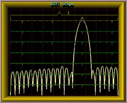
The digital matched filter that computes “I”
and “Q” is designed in an interactive manne
r
using a TTY and oscilloscope for graphical
display. The filter’s passband width an
d
impulse response length are chosen by the
user, and the RVP8 constructs the filte
r
coefficients using built-in design software.
The frequency response of the filter can be
displayed and compared to the frequency
content of the actual transmitted pulse.
Microwave energy can come from a variety of transmitters such as ground-based, ship-based or
airborne radars as well as communications links. These can cause substantial interference to a
weather radar system. Interference rejection is provided as standard in the RVP8. Three different
interference rejection algorithms are supported.
The RVP8/Rx board places the wide dynamic range “I” and “Q” samples directly on the PCI bus
where they are sent to the processor section of the PC (e.g., dual Pentium processors on a single-
board computer or motherboard). The I/Q values are then processed on the Pentium processors to
extract the moment information (Z, V, W and optional polarization parameters).
The I and Q values can also be placed on a gigabit Ethernet line (1000 BaseT) which is provided
directly on the processor board. This means that there is no second PCI bus “hit” required to send the
data to a recording system or a completely separate processing system.
166
1.4 RVP8 Weather Signal Processing
The processing of weather signals by the RVP8 is based on the algorithms used in the previous
generation RVP7 and RVP6. However, the performance of the RVP8 allows a different approach to
some of the processing algorithms, especially the frequency domain spectrum processing. All of the
algorithms start with the wide dynamic range I and Q samples that are obtained from the Rx card
over the PCI bus.
The resulting intensity, radial velocity, spectrum width and polarization measurements are then sent
to a separate host computer to serve as input for applications such as:
Quantitative Rainfall Measurement
Vertical Wind Profiling
ZDR Hail Detection
Tornado Detection and Microburst Detection
Gust Front Detection
Particle Identification
Target Detection and Tracking
᪽General Weather Monitoring To obtain the basic moments, the RVP8 offers the option of
several major processing modes:
Pulse Pair Mode Time Domain Processing
DFT/FFT Mode Frequency Domain Processing
Random Phase Mode for 2nd trip echo filtering
Polarization Mode Processing
N
ote that the RVP8 is the first commercial processor to perform discrete Fourier transforms (DFT) as
well as fast Fourier transforms (FFT). FFT is more computationally efficient than DFT, but the
sample size is limited to be a power of two (16, 32, 64, ...) This is too restrictive on the scan strategy
for a modern Doppler radar since this means, for example, that a one degree azimuth radial must be
constructed from say exactly 64 input I/Q values. The RVP8 has the processing power such that when
the sample size is not a power of 2, a DFT is performed instead of an FFT
These modes share some common features that are described first, followed by descriptions of the
unique features of each mode.
167
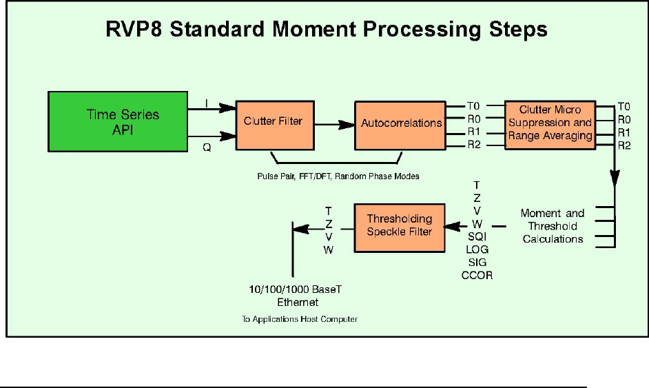
1.4.1 General Processing features
Figure 1–4 shows a block diagram of the processing steps. These are discussed below.
Autocorrelations
The autocorrelations R0, R1 and R2 are produced by all three processing modes. However, the way
that they are produced is different for the three modes, particularly with regard to the filtering that
is performed.
Pulse Pair Mode — Filtering for clutter is performed in the time domain. Autocorrelations
are computed in the time domain.
DFT/FFT Mode — Filtering for clutter is performed in the frequency domain using both
fixed width filters and the Gaussian Model Adaptive Processing (GMAP) technique.
Autocorrelations are computed from the inverse transform.
Random Phase — Filtering for clutter and second trip echo is performed in the frequency
domain by adaptive algorithms. Autocorrelations are computed from the inverse transform.
Figure 1–4: I/Q Processing for Weather Moment Extraction
The use of the R2 lag provides improved estimation of signal-to-noise ratio and spectrum width.
Processors that do not use R2 cannot effectively measure the SNR and spectrum width.
168
Time (azimuth) Averaging
The autocorrelations are based on input “I” and “Q” values over a selectable number of pulses
between 8, 9, 10, ...,256. Any integer number of pulses in this interval may be used including
DFT/FFT and random phase modes.
Selectable angle synchronization using the input AZ and EL tag lines assures that all possible pulses
are used during averaging for each, say, 1 degree interval. This minimizes the number of “wasted”
pulses for maximum sensitivity. Azimuth angle synchronization also assures the accurate vertical
alignment of radial data from different elevation angles in a volume scan (see below).
TAG Angle Samples of Azimuth and Elevation
During data acquisition and processing it is usually necessary to associate each output ray with an
antenna position. To make this task simpler the RVP8 samples 32 digital input “TAG” lines, once at
the beginning and once at the end of each data acquisition period. These samples are output in a
four-word header of each processed ray. When connected to antenna azimuth and elevation, the
TAG samples provide starting and ending angles for the ray, from which the midpoint could easily
be deduced. Since the bits are merely passed on to the user, any angle coding scheme may be used.
The processor also supports an angle synchronization mode, in which data rays are automatically
aligned with a user-defined table of positions. For that application, angles may be input either in
binary or BCD.
Range Averaging and Clutter Microsuppression
To improve the accuracy of the reflectivity measurements, the RVP8 can perform range averaging.
When this is done, autocorrelations from consecutive range bins are averaged, and the result is
treated as if it were a single bin. This type of averaging is useful to lower the number of range bins
that the host computer must process.
Range averaging of the autocorrelations may be performed over 2, 3, 4, ..., 16 bins. Prior to range
averaging, any bins that exceed the selectable clutter-to-signal threshold are discarded. This
prevents isolated strong clutter targets from corrupting the range average, which improves the sub-
clutter visibility.
Moment Extraction
The autocorrelations serve as the basis for the Doppler moment calculations,
Mean velocity – from Arg [ R1 ]
Spectrum width – from |R1| and |R2| assuming Gaussian spectrum
dBZ – from R0 with correction for ground clutter, system noise and gaseous attenuation.
Uses calibration information supplied by host computer.
dBT – identical to dBZ except without ground clutter.
These are the standard parameters that are output to the host computer on the high-speed
Ethernet interface.

169
Thresholding
The RVP8 calculates several parameters that are used to threshold (discard) bins with weak or
corrupted signals. The thresholding parameters are:
Signal quality index (SQI=|R1|/R0)
LOG (or incoherent) signal-to-noise ratio (LOG)
SIG (coherent) signal-to-noise ratio
CCOR clutter correction
These parameters are computed for each range bin and can be applied in AND/OR logical
expressions independently for dBZ, V and W.
Speckle Filter
The speckle filter can be selected to remove isolated single bins of either velocity/width or intensity.
This feature eliminates single pixel speckles which allows the thresholds to be reduced for greater
sensitivity with fewer false alarms (speckles). Both a 1D (single azimuth ray) and 2D (3 azimuth rays
by 3 range bins) are supported.
Velocity Unfolding
A special feature of the RVP8 processor is its ability to “unfold” mean velocity measurements based
on a dual PRF algorithm. In this technique two different radar PRF’s are used for alternate N-pulse
processing intervals. The internal trigger generator automatically produces the correct dual-PRF
trigger, but an external trigger can also be applied. In the later case, the ENDRAY_ output line
p
rovides the indication of when to switch rates. The RVP8 measures the PRF to determine which rate
(high or low) was present on a given processing interval, and then unfolds based on either a 2:3, 3:4
or 4:5 frequency ratio. Table 1–1 gives typical unambiguous velocity intervals for a variety of radar
wavelengths and PRF’s.
Table 1–1: Examples of Dual PRF Velocity Unfolding
Unambiguous Velocity (m/s) for Various Radar Wavelengths
PRF1 PRF2
Unambiguous
Range (km) 3 cm 5 cm 10 cm
500 * 300 3.75 6.25 12.50 No
1000 * 150 7.50 12.50 25.00
U f
ldiUnfoldi
ng
2000 * 75 15.00 25.00 50.00
500 333 300 7.50 12.50 25.00 Two
1000 667 150 15.00 25.00 50.00 TiTimes

170
Unambiguous PRF1 PRF2 Range (km) 3 cm 5 cm 10 cm
Three
Times U f
ldi
Unfolding
Four
Ti
Times
1.4.2 RVP8 Pulse Pair Time Domain Processing
Pulse pair processing is done by direct calculation of the autocorrelation. Prior to pulse pair
processing, the input “I” and “Q” values are filtered for clutter using a a time domain notch filter.
Filters of various selectable widths are available for either 40 or 50 dB stop band attenuation. The
filtered I/Q values are processed to obtain the autocorrelation lags R0, R1 and R2. The unfiltered
power is also calculated (T0). The autocorrelations are then sent to the range averaging and moment
extraction steps.
1.4.3 RVP8 DFT/FFT Processing
The DFT/FFT mode allows clutter cancelation to be performed in the frequency domain. DFT is used
in general, with FFT’s used if the requested sample size is a power of 2.
Three standard windows are supported to provide the best match of window width to the
spectrum dynamic range:
Rectangular
Hamming
Blackman
Exact Blackman
Von Han
After the FFT step, clutter cancelation is done using a selectable fixed width filter that interpolates
across the noise or any overlapped weather or an adaptive filter which automatically determines the
optimal width. This technique preserves overlapped weather as compared to time domain notch
filters which will always attenuate overlapped weather to some extent, depending on the spectrum
width. After clutter cancelation, R0, R1 and R2 are computed by inverse transform and these are
used for moment estimation.
500 375 300 11.25 18.75 37.50
1000 750 150 22.50 37.50 75.00
2000 1500 75 45.00 75.00 150.00
500 400 300 15.00 25.00 50.00
1000 800 150 30.00 15.00 100.00
2000 1600 75 60.00 100.00 200.00
171
1.4.4 Random Phase Processing for 2nd Trip Echo
Second trip echoes can be a serious problem for applications that require operation at a high PRF.
Second trip echoes can appear separately or can be overlaid on first trip echoes (second trip
obscuration). The random phase technique separates the first and second trip echoes so that:
In nearly all cases, the 2nd trip echo can be removed from the first trip even in the case
of overlapped 1st and 2nd trip echoes. The benefit is a clean first trip display.
The 2nd trip echoes can be recovered and placed at their proper range at 1st trip/2nd trip
signal ratios of up to 40 dB difference for overlapped echoes. Because of the wide dynamic
range of weather echoes, this power limit will sometimes be exceeded.
The technique requires that the phase of each pulse be random. Digital phase correction is then
applied in the processor for the first and second trips. The critical step is the adaptive filter which
removes the echo of the other trip to increase the SNR. Magnetrons have a naturally random phase.
For Klystron radars, a digitally controlled precision IF phase shifter is required. The RVP8
provides an 8-bit RS422 output for the phase shifter.
For more information on the technique refer to Joe, et. al., 1995.
1.4.5 Polarization Mode Processing
Polarization processing uses a time domain autocorrelation approach to calculate the various
parameters of the polarization co-variance matrix, i.e., ZDR, LDR, PHIDP, RHOHV, PHIDP (KDP),
etc. In addition, the standard moments T, V, Z, W are also calculated. Which parameters are
available and which algorithms are used to calculate them depends on the type of polarization radar,
e.g., single channel switching, simultaneous transmit and receive (STAR), dual channel switching.
SIGMET, Inc. is licensed by US National Severe Storms Laboratory (NSSL) to use the STAR
hardware and processing techniques and algorithms.
Polarization measurements require special calibration of the ZDR and LDR offsets. The use of a
clutter filter for the polarization variables can sometimes bias the derived parameters. Because of this,
the user decides whether or not to use filtered or unfiltered time series.
1.4.6 Output Data
The RVP8 output data for standard moment calculations consist of mean radial velocity (V),
Spectrum Width (W), Corrected Reflectivity(Z or dBZ) and Uncorrected Reflectivity (T or dBT).
Other data outputs include I/Q time series, DFT/FFT power spectrum points and polarization
parameters. The output can be made in either 8 or 16-bit format. 8-bit format is preferred over 16-
bit format for most applications since the accuracy is more than adequate for an operational radar
system, and the data communications are reduced by 50%. 16-bit formats are sometimes used by
research customers for data archive purposes. Note that time series and DFT are always 16-bit
formats. All data formats are documented in Chapter 6 of this manual.
A standard output is the I/Q time series on gigabit network (1000 BaseT). These are sent via UDP
broadcast to an I/Q archiving system or even a completely independent parallel processing system.
172
1.5 RVP8 Control and Maintenance Features
1.5.1 Radar Control Functions
The RVP8 also performs several important radar control functions:
Trigger generation- up to 6 programmable triggers.
Pulsewidth control (four states controlled by four bits).
Angle/data synchronization- to collect data at precise azimuth intervals (e.g., every 0.5,
1, 1.5 degrees) based on the AZ/EL angle inputs.
Phase shifter- to control the phase on legacy Klystron systems. New or upgrade Klystron
or TWT systems can use the RVP8/Tx card to provide very accurate phase shifting.
ZDR switch control- for horizontal/vertical or other polarization switching scheme.
AFC output (digital or analog) based on the burst pulse analysis for magnetron systems.
Pulsewidth and trigger control are both built into the RVP8. Four TTL output lines can be
programmed to drive external relays that control the transmitter pulsewidth. The internal trigger
generator drives six separate lines, each of which can be programmed to produce a desired waveform.
The trigger generator is unique in that the waveforms are stored in RAM and can be modified
interactively by user software. Thus, precisely delayed and jitter-free strobes and gates can easily be
produced. For each pulsewidth there is a corresponding maximum trigger rate that can be generated.
N
ote, however, that the RVP8 can also operate from an external use
r
-supplied trigger. In either case,
the processor measures the trigger period between pulses so that user software can monitor it as
needed.
The RVP8 also supports trigger blanking during which one or more (selectable) of the transmit
triggers can be inhibited. Trigger blanking is used to avoid interference with other electronic
equipment and to protect nearby personnel from radiation hazard. There are two techniques for this:
2D AZ/EL sector blanking areas can be defined in the RVP8 itself.
An external trigger blanking signal (switch closure to ground, TTL or RS422) can be
supplied, for example from a proximity switch that triggers when the antenna goes below a safe
elevation angle or connected to the radome access hatch.
173
1.5.2 Power-Up Setup Configuration
The RVP8 stores on disk an extensive set of configuration information. The purpose of these data is
to define the exact configuration of the RVP8 upon startup. The setup information can be accessed
and modified using either a local keyboard and monitor, or over the network. For multiple radar
networks, the configuration management can be centrally administered by copying tested “master”
configuration files to the various network radars. It is not necessary to go to the radar to change
ROM’s as was the case for previous generation processors.
1.5.3 Built-In Diagnostics
On power-up, the RVP8 performs a sequence of internal self-tests. The test sequence requires
about four seconds to perform, and tests approximately 95% of the internal digital circuitry. Errors
are isolated to specific sections of the board as much as possible. If any check fails, the user can be
certain that some component is not functioning correctly. However, there is a very small chance
that even a defective board may pass all the tests; the failure may be in one of the few areas that can
not be checked.
The RVP8 displays the test results on the LED front panel (for a standard SIGMET chassis). In this
way, there is immediate visual confirmation of the diagnostic tests, even if the host computer has not
yet been connected. The local keyboard and monitor or a networked workstation can be used to see
the test results in the TTY menus or even invoke a power–up reset and test.
174
1.6 Support Utilities and Available Application Software
The RVP8 system includes a complete set of tools for the calibration, alignment and
configuration of the RVP8. These includes the following utilities:
ascope-a comprehensive utility for manual signal processor control and data display of
moments, times series and Doppler spectra. ascope includes a realistic signal simulator capable
of producing both first and second trip targets. Recording/playback of time series and moments
is included as well.
dspx-an ASCII text-based program to access and control the signal processor, including
providing access to the local setup menus.
speed- a performance measuring utility.
DspExport-exports the RVP8 to another workstation over the network. This allows
utilities on a remote network to run locally, as opposed to exporting the utility display window
over the network.
setup- interactive GUI for creating/editing the RVP8 configuration files.
zauto- calibration utility for use with a test signal generator.
These tools can be run locally on the RVP8 itself or over the network from a central maintenance
facility. The DspExport utility improves the performance of the utilities for network applications by
letting them be run on the workstation that is remote from the RVP8. Note that standard X–Window
export is of course supported but requires more bandwidth.
In addition, complete radar application software can be purchased from SIGMET:
IRIS/Radar on a separate PC, interfaces to the RVP8 by 100 BaseT Ethernet.
IRIS/Radar controls both the RVP8 and the SIGMET RCP8 radar/antenna control processor. The
package provides complete local and remote control/monitoring, data processing and
communication for a radar system.
IRIS/Analysis (and options) runs on a separate PC, often at a central site. One
IRIS/Analysis can support up to 20 radar systems. This functions as a radar product generator
(RPG) to provide outputs such as CAPPI, rain accumulations, echo tops, automatic warning and
tracking, etc. Optional software packages are provided for special applications: wind shear and
microburst detection, hydrometeorology with raingage calibration and subcatchments, composite,
dual Doppler and 3D Display.
IRIS/Web provides IRIS displays to network users on standard PC’s (Windows or
Linux) running Netscape or Internet Explorer.
IRIS/Display can display products sent to it and, with password authorization, can serve
as a remote control and monitoring site for networked radar systems. Features such as looping,
cross–section, track, local warning, annotation, etc. are all provided by IRIS/Display. Note that
both IRIS/Analysis and IRIS/Radar have all of the capabilities of IRIS/Display in addition to
their own functions. This means that any IRIS system can display products.
175
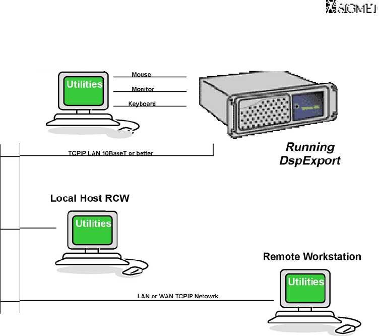
1.7 System Network Architecture
The RVP8 provides considerable flexibility for network operation. This allows remote
control and monitoring of the system from virtually anywhere on the network, subject to
the user’s particular security restrictions.
Unlike the previous generation RVP7, which used a SCSI interface, the RVP8 uses a
network interface exclusively. The “dsp lib” runs locally on the RVP8 and a utility,
called DspExport, exports the library over the network using a TCP/IP socket. Typically
this is exported to a local host radar control workstation (RCW) on the network. Perhaps
this workstation is running the SIGMET IRIS software. At least 10BaseT connection is
recommended for this connection.
Figure 1–5: Network Architecture for Socket Interface with DspExport
Socket Interface Connections
RVP8
Local Keyboard, Mouse, Monitor
Running
DspExport
Mouse
Monitor
Keyboar
d
A remote workstation on the network can also use the DspExport technique to
communicate for configuration, monitoring and diagnostic testing.
176
1.8 Open Architecture and Published API
SIGMET recognizes that certain users may require the ability to write their own signal processing
algorithms which will run on the RVP8. To accommodate this, the RVP8 software is organized to
allow separately compiled plug-in modules to be statically linked into the running code. The
application program interface (API) allows user code to be inserted at the following stages of
processing:
Tx/Rx waveform synthesis and matched filter generation— The API allows the transmit
waveforms to be defined from pulse to pulse, along with the corresponding FIR coefficients that
will extract (I,Q) from that Tx waveform. This allows users to experiment with arbitrary
waveforms for pulse compression and frequency agility.
Time series and spectra processing from (I,Q)- The API allows you to modify the default
time series and spectra data, e.g., to perform averaging or windowing in a different way.
Parameter generation from (I,Q)- This is probably where the greatest activity will occur
for user–supplied code. The API allows you to redefine how the standard parameters (dBZ,
Velocity, Width, PHIDP, etc.) are computed from the incoming (I,Q) time series. You may also
create brand new parameter types that are not included in the basic RVP8 data set.
N
ote that the standard SIGMET algorithms are not made public in this model. Rather, the interface
hooks and development tools are provided so that users can add their own software extensions to the
RVP8 framework. Many of the library routines that are fundamental to the RVP8 are also
documented and can be called by user code; but the source to these routines is not generally released.
Development tools which are not under public license must be purchased separately by the customer.
While most customers will use the signal processing software supplied by SIGMET, the new open
software architecture approach employed by the RVP8 will be very useful to those research
customers who want to try innovative new approaches to signal processing, or to those OEM
manufacturers who are interested in having their own “custom” stamp on the product.
177
1.9 RVP8 Technical Specifications
1.9.1 IFD Digitizer Module, Rev E or later
Input Signals ᪽IF Received Signal: 50᪽, + 6.5 dBm full–scale, +20dBm
absolute max ᪽IF Burst or COHO: 50᪽, +6.5 dBm full–scale, +20dBm absolute
max
᪽Optional Reference Clock: 2–60 MHz –10 to 0 dBm
IF Ranges:
᪽12—34 MHz, 38—70 MHz
Linear Dynamic Range
᪽85 to >100dB depending on pulsewidth/bandwidth filter
A/D Conversion
Resolution 14 bit with jitter <2.5 picosec
Sampling rate 67 to 79 MHz (selectable, standard is 71.9364 MHz)
AFC Output
Analog –10 to +10V
Optional Digital AFC (DAFC) with up to 24 programmable output bits.
Automatic 2-D (time/frequency) burst pulse search and fine tracking algorithms.
IFD Link
᪽Uses shielded CAT 5E cable, non standard signals, requires RVP8/Rx card, rev C or later.
Cable length to RVP8/Rx
᪽2—25 meters, with automatic calibration of round trip time and range correction.
178
1.9.2 RVP8/Rx PCI Card, Rev C or later
Pulse Repetition Frequency
᪽50 Hz to 20 KHz +0.1%, continuously selectable.
IF Band Pass Filter
᪽Programmable Digital FIR with software selectable bandwidth. Built-in filter design
software with graphical user interface.
Impulse Response
᪽Up to 3024 FIR filter taps, corresponding to 75 ᪽sec impulse response length for 72
MHz IF samples at 125 meter range resolution. These very long filters are intended for use with
pulse compression.
Range Resolution
᪽Minimum bin spacing of 25 meters selectable in N*8.33 meter steps. Bins can be
positioned in a configurable range mask with resolution of N* the fundamental bin
spacing, or arbitrarily to an accuracy of ±2.2 meters.
Maximum Range
᪽Up to 1024 km
Number of Range Bins
᪽Full unambiguous range at minimum resolution or 3096 range bins (whichever is less).
The RVP8 processor may only be fast enough to process an average of 50 meter bins.
Electrical Interfaces
᪽CAT 5E cable from the IFD, rev E or
later.
᪽BNC #1 for trigger output (12V, 75᪽), or pretrigger
input. BNC #2 for trigger output (12V, 75᪽).
᪽9-pin “D” connector supporting four RS-422 differential signals for miscellaneous input
and output with SoftPlane᪽ support. Each line pair can operate as a transmitter or as a receiver
depending on what’s needed. Possible uses are: alternate reference clock input, gating input for
CW modes, additional trigger outputs, external phase shift requests, etc.
Data Output via PCI Bus
16-bit floating I and Q values
14-bit raw IF samples
179
1.9.3 RVP8/Tx PCI Card
Analog Waveform Applications
Digitally synthesized IF transmit waveform for pulse compression, frequency agility, and
phase modulation applications.
Master clock or COHO signal to the radar; can be phase locked or free running, arbitrary
frequency.
Analog Output Waveform Characteristics
᪽Two independent, digitally synthesized, analog output waveforms (BNC). These two
outputs are electrically identical and logically independent IF waveform synthesizers that can
produce phase modulated CW signals, finite duration pulses, compressed pulses, etc.
᪽Can drive up to +12dBm into
50᪽.
᪽14-bit interpolating TxDAC provides 71dB Signal-to-Noise
Ratio.
᪽IF center frequency selectable from 8 to 32.4 MHz, and from 48.6 to 75MHz.
᪽Signal bandwidth as large as 15MHz for wideband/multiband Tx applications. Band
width is adjustable in software.
᪽Continuous or pulse modulated output with band width limiting on pulse modulation
output.
᪽Precise phase shifting with transient band width
limiting.
᪽Total harmonic distortion less than –
74dB.
᪽Waveform pre-emphasis compensates for both static and dynamic Tx nonlinearities.
Other I/O signals
᪽Clock In/Out 50᪽ SMA connector. This can receive a CW reference frequency to which
the RVP8/Tx can lock to a P/Q frequency multiple (much like the RVP8/IFD can lock to an
external reference). This connector can also supply the TxData Clock, optionally divided by
some N between 1 and 16, in order to supply external circuitry with +10dBm clock reference at
50᪽.
᪽9-pin “D” connector supporting four RS-422 differential signals for miscellaneous input
and output with SoftPlane᪽ support. Each line pair can operate as a transmitter or as a receiver
depending on what’s needed. Possible uses are: alternate reference clock input, gating input for
CW modes, additional trigger outputs, external phase shift requests, etc.

180
1.9.4 SIGMET I/O-62 PCI Card
Short format PCI card with 62-position “D” connector. Multiple cards may be installed.
Includes D/A, A/D, discrete inputs and outputs (TTL, wide range, RS422, etc.) See
summary table below.
I/O pin assignment mapping by softplane.conf file.
Standard or custom remote backpanels available.
᪽ESD protection using Tranzorb᪽ silicon avalanche diode surge suppressio
n
and high-voltage tolerant components.
SIGMET I/O-62 Summary of Electrical Interfaces
Qty Description
40 Lines configurable in groups of 8 to be either inputs or outputs. The electrical specifications are
software defined within each group as follows: ᪽Single-ended TTL input or output with
software–configured pull-up or pull-down resistors for inputs. ᪽Wide range inputs (᪽27VDC,
threshold +2.5VDC), often used for “lamp voltage” status inputs. ᪽RS-422/485 @ 10 MBit/sec
(requires two lines each). RS-422 receivers can be configured in software to have 100᪽
termination between each pair.
8A/D convertors configurable as 0, 4, or 8 convertors, ᪽2V, 12 bits @ 10 MHz, These lines are
shared with some of the 40 I/O lines listed above.
2D/A convertors, ᪽10V 1 MHz update rate, output can drive a 75᪽ load.
2SPDT relays on the board. These are often used for switching high power relays. Contacts are
diode protected.
2 RS-232C full duplex lines (Tx and Rx)
412V 75᪽ trigger drivers .
2 Power/Ground pairs of 12V power (filtered, fused) for external equipment or remote backpanel
use (up to 24 W total). Polyfuse technology acts like a circuit breaker with auto reset in the event
of an overload.
8 Ground wires for signal grounds from the remote back panel.

181
1.9.5 I/O-62 Standard Connector Panel
Mounts on front or rear of standard 19” EIA rack
Connects to I/O-62 via 1:1 62–pin 1.8–m cable (provided).
Provides standard inputs and outputs required by most weather radars such as triggers,
polarization control, pulse width control and antenna angles.
Az and El synchro and reference inputs (nominal 100V 60 Hz)
3 internal relays and 4 12V relay control signals for switching external devices.
Programmable scope test points with source waveforms selectable in software.
Diagnostic power supply and self test LED’s for troubleshooting.
RVP8 Connector Panel Summary
J-ID Label Type Description
J1 AZ INPUT DBF25 Up to 16–bits of parallel TTL binary or BCD angle
J2 AZ OUTPUT DBF25 Up to 16–bits of parallel TTL binary or BCD angle
J3 PHASE OUT DBF25 Up to 8–bits of parallel TTL or RS422. Angles are configurable.
J4 EL INPUT DBF25 Up to 16–bits of parallel TTL binary or BCD angle
J5 EL OUTPUT DBF25 Up to 16–bits of parallel TTL binary or BCD angle
J6 RELAY DBF25 3 internal relays, contact rating 0.5 A continuous. The switching
load is 0.25 A and 100V, with the additional constraint that the
total power not exceed 4VA. 4, 12V relay control signals, up to
200mA. (Note that external relays should be equipped with proper
diode protection to shunt the back EMF).
J7 SPARE DBF25 20 additional TTL I/O lines each configurable to be input or
output.
J8 SPARE DBF25 10 differential analog inputs, up to ±20V max multiplexed into
A/D convertor sampling each at >1000 Hz.
J9 MISC I/O DBF25 7 additional RS422 lines and 2 each dedicated (non–multiplexed)
A/D inputs (±580V with pot adjust) and D/A outputs (±10V).
J10 SERIAL DBF9 RS232C
J11 SERIAL DBF9 RS232C
J12 S–D Modular 3 x 4 matrix connector for AZ and EL synchro and reference inputs
J13 TP–1 BNC Programmable scope test point. 75 Ohms
J14 TP–2 BNC Programmable scope test point. 75 Ohms
J15 TRIG–1 BNC 12V trigger into 75 Ohms
J16 TRIG–2 BNC 12V trigger into 75 Ohms
J17 TRIG–3 BNC 12V trigger into 75 Ohms
J18 TRIG–4 BNC 12V trigger into 75 Ohms
182
1.9.6 RVP8 Processing Algorithms
Input from Rx Board
16-bit I/Q samples
Optional dual-channel I/Q samples (e.g., for polarization systems or dual frequency
systems)
IQ Signal Correction Options
Amplitude jitter correction based on running average of transmit power from burst pulse.
Interference correction for single pulse interference
Saturation correction (3 to 5 dB)
Primary Processing Modes
Poly-Pulse Pair (PPP) ᪽DFT
Random or Phase Coded 2nd trip echo filtering/recovery
Optional Polarization with full co-variance matrix (ZDR, PHIDP, LDR, RHOHV, etc.)
Optional Pulse Compression
Processing Options
FIR Clutter filters (40 and 50 dB) in pulse pair mode.
Adaptive width clutter filters in DFT and phase coded 2nd trip mode.
Velocity De-Aliasing: Dual PRF Velocity unfolding at 3:2, 4:3 and 5:4 PRF ratios or
Dual PRT Velocity processing for selectable inter-pulse intervals.
Range De-aliasing: Phase coding method (random phase for magnetron) Frequency
coding method (not available for magnetron)
Scan angle synchronization for data acquisition.
Pulse integration up to 1024
Corrections for gaseous attenuation and 1/R2.
Up to 4 pulse widths
Data Outputs
dBZ Calibrated equivalent radar reflectivity, 8 or 16 bits
V Mean radial velocity, 8 or 16 bits
183
W Spectrum width, 8 or 16 bits
I/Q Time series, 16 bits each per sample
DFT Doppler Spectrum output option in DFT mode, 16 bits per component
Optional: ZDR, PHIDP, RHOHV, LDR, RHO, 8 or 16 bits
Data Quality Thresholds
Signal–to–noise ratio (SNR) Used to reject bins having weak signals. Typically
applied to dBZ.
Signal quality index (SQI) Used to reject bins having incoherent signals. Typically
applied to mean velocity and width.
Clutter-to-signal ratio (CSR) Used to reject range bins having very strong clutter.
Typically applied to mean velocity, width and dBZ.
Speckle Filter Filter removes single-bin targets such as aircraft or noise Fills isolated
missing pixels as well.
184
1.9.7 RVP8 Input/Output Summary
Ethernet Input/Output from Host Computer
᪽Data output of calibrated dBZ, V and W during normal operation. Full I/Q timeseries
recording with a separate tsarchive utility, or through a customer’s application using a public
API. Signal processor configuration and verification read–back is performed via the Ethernet
interface.
RS-232C Serial Data I/O
᪽For real time display/monitoring or data remoting.
AZ/EL Angle Input Options
Serial AZ/EL angle tag input using standard SIGMET RCP format.
16-bit each parallel TTL binary angles via the I/O-62 card.
Synchro angle inputs via the I/O-62 card.
SIGMET network antenna packet protocol.
Trigger Output
᪽Up to 10 total triggers available on various connector pins. Triggers are programmable
with respect to trigger start, trigger width and sense (normal or inverted).
Optional Polarization Control
᪽RS-422 differential control for polarization switch.
185
1.9.8 Physical and Environmental Characteristics
Packaging
᪽Motherboard Configuration 4U rack mount with 6 PCI slots
᪽Custom PC configurations available or packaged by customer.
᪽Dimensions of standard 4U chassis
43.2 wide x 43.2 long x 17.8 cm high 17
wide x 17 long x 7.00 inch high
᪽Dimensions IF Digitizer
2.5 wide x 10.9 long x 23.6 cm high 1
wide x 4.3 long x 9.3 inch high
᪽Redundant Power Supplies. Three hot–swap modules with audio failure alarm.
Input Power
IFD 100–240 VAC 47–63 Hz auto–ranging
Main Chassis 60/50 Hz 115/230 VAC Manual Switches
Power Consumption
RVP8/Main Processor 180 Watts with Rx and Motherboard
RVP8/IFD IF Digitizer 12 Watts
Environmental
Temperature 0C (32F) to 50C (122F)
Humidity 0 to 95% non–condensing
Reliability
᪽MTBF>50,000 hours (based on actual RVP7 field data).