Basys Technology PAT2 Theft Deterrent Transmitter User Manual Manual
Basys Technology Ltd Theft Deterrent Transmitter Manual
Contents
Manual

ParSec Reader Installation Manual - Issue:2 - January 1998 - Page 1
ParSec READER
INSTALLATION MANUAL
Part No: IM016
Issue 2 January 1998
Newmark Technology Ltd
21-23, Ormside Way
Redhill
Surrey
RH1 2NT
United Kingdom
Tel:+44(0) 1737 788800
Fax:+44(0) 1737 779535
Web site: www.newmarkworld.com
Document No: A/IM 230 800 Prepared by: Alan Francis &
Jon Hart
ParSec Reader Installation Manual - Issue:2 - January 1998 - Page 2
ParSec READER
INSTALLATION MANUAL
CONTENTS
1 Caution - Static Precautions
2 General Installation Notes
2.1 Reader Design
2.2 Siting the reader
2.3 Power Supply Requirements
2.4 Communications Interfaces
2.4.1 RS-232 Data Port
2.4.2 Wiegand Data Port
2.5 External PIR Operation
3 Installing the reader
3.1 Fixing the Reader Enclosure
3.2 Installing the Backplane Pcb
3.3 Installing the Logic Pcb
4 Commissioning the Reader
4.1 Default Switch Settings
4.2 Adjusting the read Range
4.2.1 Range Adjustment Procedure
4.3 Setting the Reader Identity
4.3.1 Reader Number Programming
4.3.2 Sub-system Code Programming
4.4 Setting the Indicators & Alarm Functions
4.4.1 Indicator LED Programming
4.4.2 Internal Sounder Programming
4.4.3 Alarm Relay Timer Programming
4.5 PIR Operation
4.5.1 The Internal PIR
4.5.2 Using an External PIR
4.6 Setting up the Communications Interfaces
4.6.1 Baud Rate Programming for RS-232 Data Comms.
4.6.2 Adjusting Static Tag Sensitivity
5 Troubleshooting
5.1 Reader Reset
5.2 Tags not read
6 Service & Repair
7 Change Record
ParSec Reader Installation Manual - Issue:2 - January 1998 - Page 3
1. CAUTION - STATIC PRECAUTIONS
Some devices used in the ParSec reader are static sensitive.
Anti-static precautions must be taken when handling the printed circuit boards.
Static discharge will permanently damage the boards.
2. GENERAL INSTALLATION NOTES
2.1. Reader Design
The reader is mounted in a 2-part enclosure for surface mounting. The rear casing has 2
keyholes and 1 slotted hole for the 3 fixing screws and a variety of knock-out positions for
ease of cable entry.
The reader contains two PCB’s for ease of installation and maintenance. The rear BACKPLANE
PCB comprises two cable termination blocks, the power supply regulator and alarm relay, and
two connectors to the front LOGIC PCB. The Backplane PCB will normally remain
permanently mounted after the reader case has been sited and the cables installed.
The LOGIC PCB contains the radio receiver, the microprocessor and communications circuitry,
and the KEYPIC personality module. All reader adjustment and configuration is performed via
the logic PCB, which is mounted onto the Backplane PCB via two push-fit connectors.
This method of construction enables replacement of the logic PCB for maintenance purposes
and also makes it possible for the physical mounting and cabling of the reader enclosure and
Backplane to be carried out prior to system configuration and commissioning.
The reader front cover is protected from unauthorised entry by a recessed security screw.
For this to be removed for installation, you will need a Newmark security driver (Part no
SS0001 or RS part 541-983). Any attempt to remove the front cover will operate an anti-
tamper switch which may be set to trigger a local or remote alarm (e.g. sounder/lamp) and, if
the reader is connected to a computer-based system, to raise an alarm at the system control
console.
There are 2 types of reader. The model PSR-232-1 has an RS232 port and is normally used
with TransAsset or other third party asset management software. The model PSR-W26-1 has
a 26-bit industry standard wiegand card type data output and is normally used with access
control systems. It is possible to convert from 1 model to another by simply changing the
socketed KeyPIC.
All the tags transmit at 418 MHz using a power level which in the UK is MPT 1340 licence
exempt by the DTI. For those countries where 418 MHz is not acceptable, tags and readers
operating at 433 MHz will become available in mid 1998. All units are CE marked and
comply with European EMC directives. However, to maintain this compliance, it is essential
that you follow the installation procedures in this manual and in particular use grounded
screened cables where specified.
ParSec Reader Installation Manual - Issue:2 - January 1998 - Page 4
2.2. Siting the reader
The physical location chosen to site each reader will depend principally upon
(1) The area of coverage required for Static Asset Tags (PS-SAT1-1’s).
(2) The exit/entry points to be protected or monitored with Portable Asset Tags
(PS-PAT1-1’s) and Personnel Tags (PS-PET1-1’s).
For 'portal monitoring' with PS-PAT1-1’s and PS-PET1-1’s, the reader should be sited in line
with the centre of the doorway and midway between the top of the door and the ceiling. (This
is not critical and, in some cases, it may be appropriate to site the reader in a higher position
to deter vandalism.)
Where the system is used solely for monitoring unauthorised movement of items protected by
PS-SAT1-1’s, the reader should be mounted 0.5m below the ceiling and in the centre of a
convenient wall in the location, to optimise the polar pattern of the receiving antenna.
Up to nine of the RS232 type readers can be chained to provide extended coverage of a wide
or irregularly shaped area. (For details of reader addressing, see section 4.3.)
Notes
"DIFFICULT" LOCATIONS
(1) The reader enclosure is partially screened to reduce the sensitivity to tags from
the rear. Where REAR DETECTION is a problem, a new type of uni-directional
antenna is being developed. Contact your supplier or Newmark for more
information.
(2) The reader is supplied with aluminium shield which can be fitted to the reader
after installation to reduce its sensitivity to tags being read through the ceiling
from the floor above. If this is required, peel off the self-adhesive backing
strip and place it inside the top of the reader enclosure. Note that it covers the
2 upper fixing screw holes, so you will need to use countersunk head fixing
screws.
(2) The presence of steel girders, metal filing cabinets/office furniture, false ceiling
supports and aluminium backed plasterboard in the building structure will
cause reflections and will cause blind areas and hot spots. If this occurs, it will
be necessary to move the reader to an alternative location, which may be as
little as 10 cm away in some cases. Installation survey equipment will be
available from Newmark in due course. Radio signals can often travel down
corridors, lift shafts and may even go round corners. Always try and test the
reader temporarily in the intended location first to check that it will work
properly in that location.
(3) Peoples bodies absorb the tag transmissions and it is always good practice to
ParSec Reader Installation Manual - Issue:2 - January 1998 - Page 5
mount the reader as high as possible or even facing downwards from the
ceiling so that bodies do not shield the reader. In some cases it may be
necessary to mount more than 1 reader to provide adequate coverage.
(3) The readers are not weather-resistant and so must only be mounted outside in
an all plastic suitably rated enclosure.
CAUTION
In common with all low power radio frequency based systems, ParSec Universal Readers
should be sited as far away as practicable from sources of electromagnetic interference.
Whilst the internal surfaces of ParSec Readers are partially screened, it is strongly advised
that they should not be mounted close to VDU screens, TV monitors or other sources of radio
frequency emission. The minimum recommended separation is 1.5m from a 15 inch CRT
screen.
2.3. Power Supply Requirements
The reader requires a 12V/300mA, DC power supply, which must be CE approved.
The on board voltage regulator allows the input voltage to vary +/- 3 volts from the nominal
12 volt supply. The reader is protected against reverse polarity but not voltages greater than
16V.
It is recommended that power and signal cables to the reader should be separated from 3-
phase mains supplies by at least 1m and from single phase mains supplies and all types of
cable runs by at least 0.5m. Use screened cables e.g. 2-core Belden 8760 for reader power,
2-core Belden 8761, 9841 or 9501 for RS-232 and 6-core screened e.g. Belden 9536 for
Wiegand data and LED drive. Connect the screen to earth/ground at the remote end.
2.4. Communications Interfaces
2.4.1. RS-232 Data Port (PSR-232-1 model only)
Serial data input and output connections and switch settings are detailed in Section 4.6.1. Full
details of the RS-232 protocol are contained in the separate document “ParSec reader RS-232
Data Specification”.

ParSec Reader Installation Manual - Issue:2 - January 1998 - Page 6
2.4.2. Wiegand Data Port (PSR-W26-1 model only)
Wiegand data format allows ParSec Readers to be connected directly to access control
systems using this standard. This 26-bit version uses the industry standard format as follows.
Bit 1 Even parity on bits 1-13
Bits 2 - 9 Site Code as printed on tags
Bits 10 - 25 Tag no as printed on tags
Bit 26 Odd parity on bits 14-26
Connections for use with an InterPoint are shown below.
ParSec Reader InterPoint Function
TB1 TB4
1 1(12V) 12V
2 3 (0V) 0V
8 4 (R1) D0
9 6 (R3) D1
13 7 (RED) Red LED
11 8 (GRN) Green LED
Set the InterPoint reader mode DIL switch 5 to 8 all off i.e. as for a wiegand card.
2.5. External PIR Operation
If an external PIR is used, it must be fitted with the appropriate Fresnel lens, and be fixed in
its operational position and set to the desired attitude prior to commencing the reader
commissioning procedures.
ParSec Reader Installation Manual - Issue:2 - January 1998 - Page 7
3. INSTALLING THE READER
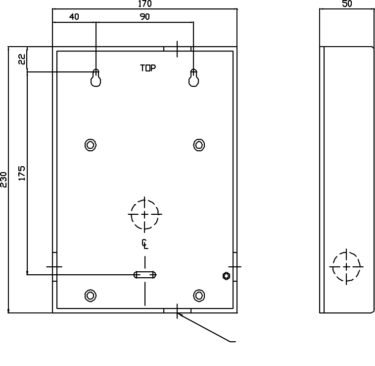
3.1. Fixing the reader enclosure
CABLE ENTRY
KNOCKOUT ∅25mm
IN 5 POS’NS
FIG. 1 - READER REAR CASE
The rear case should be fixed in position with appropriate. screws in the two upper slotted
holes and secured with a third screw in the lower hole.
ParSec Reader Installation Manual - Issue:2 - January 1998 - Page 8
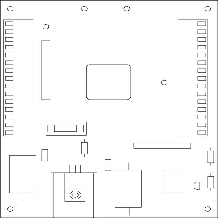
3.2. Installing the Backplane PCB
It is recommended that power and signal cables are routed via the hole in the centre of the
Backplane PCB prior to fixing the PCB and terminating the connectors.
The Backplane PCB is secured to the rear case by the four M3 screws provided.
Cable connections should be made to the two connector blocks shown below. The
designations are also shown on a label affixed to the top inside of the reader housing.
TERM 1
15
1
1
15
SK1
F1
TERM 2
D1
+C3
C4
C2
C1
RLY1
PL1
U1
Q1
D2
R1
+
FIG. 2 - BACKPLANE PCB LAYOUT
The connector blocks are of the sprung type to ensure ease of installation. Prepare each
conductor by stripping back 5 mm insulation then follow the steps below.
1. Insert a 2.5 mm screwdriver in the slot above the required terminal and twist the
screwdriver a few degrees in either direction.
2. Insert the conductor.
3. Withdraw the screwdriver to ensure a reliable connection.

ParSec Reader Installation Manual - Issue:2 - January 1998 - Page 9
TERMINAL
BLOCK
TERMINAL
NUMBER
DESIGNATION
1 1 +12 volt supply input
20V
30V
4 +5 volt output
5 Reader inhibit input
6 Long range inhibit input
7 Not used
8 Wiegand data 0 (D0) out
9 Wiegand data 1 (D1) out
10 Wiegand inhibit input
11 Green LED external input
12 Amber LED external input
13 Red LED external input
14 External sounder input
15 Data ground
2 1 External PIR +12V output
2 External PIR 0V output
3 PIR contact input
4 RS-232 data input
5 RS-232 data output
6 RS-232 data ground
7 RS-232 bypass (looped to 8)
8 RS-232 bypass (looped to 7)
9 Tamper loop from S1
10 Tamper loop to S1
11 Alarm reset input
12 Alarm 0V input
13 Alarm relay C
14 Alarm relay NC (powered down)
15 Alarm relay NO (powered down)
TABLE 1 - BACKPLANE PCB CONNECTOR DESIGNATIONS
ParSec Reader Installation Manual - Issue:2 - January 1998 - Page 10
3.3. Installing the Logic Pcb
Following installation and wiring of the Backplane Pcb, the Logic Pcb is installed by plugging
it onto the two Backplane connectors. Aligning these connectors requires care and some
practice because you are working blind. Mis-aligning them can result in bent or broken pins.
Press the connectors firmly home without exerting undue pressure on the Logic PCB.
CAUTIONS
The Logic Pcb must only be installed or removed from the Backplane Pcb with the power
supply disconnected.
Take great care to ensure that the two connectors between the Backplane and Logic Pcbs
are correctly located. The L-shaped layout of the connectors is designed to assist with
correct location.
Once the two Pcbs are firmly mated, refit the M3 screw and washer.
4. COMMISSIONING THE READER
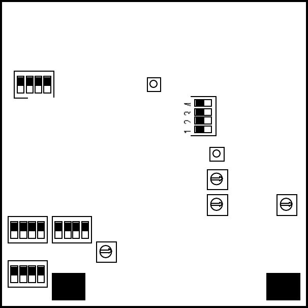
Figure 3 shows the layout of the switches on the reader Logic Pcb which are used to
configure the reader to its required installation settings. It is important that the commissioning
procedure is performed strictly in the sequence which follows.
1 2 3 4
1 2 3 4
4 3 2 4 3 2
S11
S14 S13
S4
S10 S1
S6
S5
S15
S3
S2
S12
S9
FIG.3 - LOGIC PCB SWITCH LOCATIONS

ParSec Reader Installation Manual - Issue:2 - January 1998 - Page 11
4.1. Default Switch Settings
Table 2 below lists the functions of all switches on the Logic Pcb. When installing a reader for
the first time, set the switches to their default conditions shown in italics in the table.
SWITCH POLE SENSE FUNCTION
S1 Depressed Front panel tamper OFF (ON when cover removed)
S2 0-9
(0)Reader Number - Units (User set) for PSR-232-1 type only
S3 0-9
(0)Reader Number - Tens (User set) for PSR-232-1 type only
S4 1 ON Enable external sounder input (+5 to +12VDC)
2ON Enable tamper sounder (set to OFF until unit is installed and
front panel fitted)
3ON Enable static asset tag detect peep
4ON Enable portable asset tag detect peep
S5 Not used - leave all 4 sections off
S6 Press Scanner master reset (starts scanner - indicated by flashing
power LED)
S9 1-7
(3)Static asset tag pulse count setting 1=1, 7=7 (8,9 & 0 unused -
default to 1); also determines number of Static tag pulse
counts before Wiegand data output (RS-232 not affected)
S10 Depressed Front panel tamper OFF (ON when cover removed)
S11 1 ON Disable PIR usage
2OFF No external PIR set
3OFF Disable internal PIR
4OFF Enable internal LED control
(ON disables internal and enables external LED control; logic
= active low input).
S12 0-9
(4)Static asset tag alarm time setting (controls relay contacts and
internal alarm sounder)
0=2s, 1=5s, 2=10s, 3=30s, 4=1m, 5=2m, 6=5m, 7=10m,
8=15m, 9=20m
S13 1 OFF Internal sounder volume low (ON = high volume)
2OFF RS-232 data 9,600 baud (ON = 2,400 baud)
3 & 4 OFF Position dependent on sub-system code; both must match
Static asset tag switch positions;
S14 1 ON Enable Portable asset tag alarm relay
2ON Enable Static asset tag alarm relay
3ON Enable Portable & Static asset tag tamper internal alarm relay
4-Not used
S15 Press Master processor and KeyPIC reset; only used in total
data/reader lock-up condition which may be caused by bad
power or other data error
TABLE 2 - LOGIC PCB SWITCH FUNCTIONS
ParSec Reader Installation Manual - Issue:2 - January 1998 - Page 12
4.2. Adjusting the Read Range
The range at which Portable Asset and Personnel Tags is read by the reader is adjustable from
a maximum free space range of c. 25m down to a few cm. to suit the requirements of the
individual installation.
Notes (1) The nominal 100m long range reading of Static Asset Tags is not adjustable
(2) Tamper alarms, routine reports and low battery conditions are signalled by
Static and Portable Tags at high power (i.e. long range); the Personnel Tag
always signals at low power (short range).
The range of portable asset and personnel tags is adjusted by using the Range Adjusting Tag
(PS-RAT1-1)
4.2.1 Range Adjustment Procedure
1. Power on the reader
2. Press the Scan Reset button (S6) - the red power LED will flash
3. Move to the position where you would like tags to be read and press and hold down
the FIND button on the PS-RAT1-1. Within about 10 seconds the reader will then
find the RAT and set the range. This will be signified by the tone sounder on the
reader operating and the left hand red LED flashing. You can now check the range by
pressing and holding down the SEEK button on the RAT. When the reader sees the
RAT it will operate the tone sounder and the red LED.
4. If you would like to make some minor adjustment to the range you can use the + & -
buttons. Press these keys momentarily and check the red LED on the reader flashes
each time. Note that very brief presses of less than 0.3 seconds will be ignored.
5. Use the SEEK button and check the range in different locations in the area where you
want tags to be read. In all except very large open areas or outdoors, you will find
blind spots and hot spots. This is caused by the radio signals from the tag being
reflected off walls, ceilings, furniture and people.
6. Once you are satisfied with the reading range, press and release S6 and this will store
the range adjustment in the reader memory. The power LED will now show a solid
red. The range setting is stored in non-volatile memory, so it will be retained even if
the reader power is removed.
7. If at any time you wish to alter the range, you can repeat the above procedure as
many times as you like.
Notes
(1) Owing to the nature of RF at the frequencies used in the ParSec system, it may
be desirable to carry out the set up procedure a few times to optimise reader
performance to the location.
(2) Mounting Portable asset tags on metal surfaces may result in a severe loss in
range unless care is taken to find the best location. Generally these tags should
be located as near to a corner as possible with the arrow on the tag pointing to
the outside edge. Although laptop computers appear to have a plastic outer
ParSec Reader Installation Manual - Issue:2 - January 1998 - Page 13
case, there is always a metal screen behind the display. You may have to try
several different positions on a laptop before you find one that does not impair
the range. We recommend that you should always temporarily fit the tag on
assets containing metal and check the range is adequate before fixing it down
permanently. Once you have found the best position on, for example, a
particular model of laptop, you will then be able to fit the tag in the same
position for all similar models. Remember to ensure that the tamper switch
spring is pushed in when doing these tests. The tamper alarm always operates
at high power at long range. Never re-use the adhesive pads on tags.
If you have to re-locate a tag replace the adhesive pad and always de-grease
the mounting surface using methylated spirits or other de-greasing agent.
(3) The range set using the RAT is designed to compensate for the reduction in
range that occurs when asset tags are mounted on metal or when personnel
tags are worn close to the body e.g. in a pocket. You will find that tags held
clear of metal or bodies will operate at a greater range than that set by the
RAT.
(4) The level of ambient background noise will affect range consistency;
whilst noise filtering is employed in the reader design it cannot filter certain
types and levels of noise which are within the scope of the data rate. Please
refer to the Important Installation Notes in Section 2.2 ‘Siting the Reader’.
(5) If after setting the range, the red power LED continues to flash slowly, then
the range setting is invalid. Repeat the range setting process.
ParSec Reader Installation Manual - Issue:2 - January 1998 - Page 14
4.3. Setting the Reader Identity
4.3.1. Reader Number Programming
Switch S2 programs the 'units value' and S3 programs the 'tens value'. Set the required values
before applying power to the reader. Should the reader number need to be changed, select the
new number then depress the reset switch (S15); the new number will be read by the reader
software.
Notes
(1) The reader number is only reported via the RS-232 data port; it is not reported
via the Wiegand data port.
(2) It is possible to set as many Readers as required to the same reader number.
4.3.2. Sub-system Code Programming
This facility is normally only used where more than one Static Asset tag system is used at the
same location; it provides 'isolation' between adjacent systems and prevents Static tag on one
system being read spuriously by the other system.
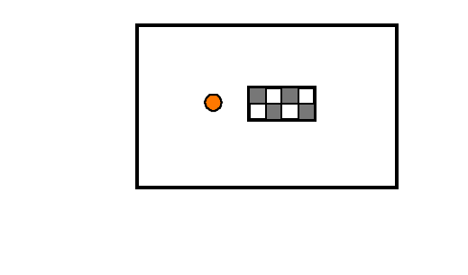
Four sub-system codes are available and they are set via switches S2/3 on the underside of
the Static tag.
Switch 1 - On/Off
Switch 2/3 - Sub-System Code
Switch 4 - Hourly Routine Report
FIGURE 4 - STATIC TAG SWITCH
LOCATIONS
The code setting on the reader
(switch S13 poles 3/4) must match the setting chosen for the Static tags belonging to that
system. Note that PS-SAT1-1 switch 2 corresponds with reader switch S13/4, and PS-SAT1-1
switch 3 with reader switch S13/3.
Notes (1) Sub-system code programming applies only to Static tags.
(2) Portable Asset tags are equipped with the same switch block but
switches 2/3 are non functional.
(3) Portable Asset tags will also give hourly routine reports if switch 4 is
turned ON.
(4) If an asset tag is moved or tampered with the next routine report will
be about an hour later. In other words the internal 1-hour timer inside
the tag is reset every time the tag transmits.
1 2 3 4
ON
OFF
Tamper

ParSec Reader Installation Manual - Issue:2 - January 1998 - Page 15
4.4. Setting the Indicators & Alarm Functions
4.4.1. Indicator LED Programming
Control of the reader status indicator LEDs is set by switch S11/4. In its default position -
OFF - the LEDs are driven by the internal control lines i.e. amber for the personnel and
portable asset tags and green for static asset tag.
Power
Static
Portable
FIGURE 5 - INDICATOR LED FUNCTIONS
All indicator LEDs are individually programmable (except the Power/Scan LED) under the
control of switch S14; see Table 3 for details of the settings.
When switch S11/4 is set to ON, the LED is diverted to the main connector panel where they
can be controlled by an external voltage source; see Section 3.2, Figure 2 for details of the
connections. The external source logic is active low. In an access control application you
may wish to use external LED control to indicate if access has been granted, denied or if the
door is permanently unlocked, locked or forced.
4.4.2 Internal Sounder Programming
The internal sounder may be programmed to selectively operate on detection of conditions
generated by
(1) Portable Tags
(2) Static Tags
(3) Tamper alarms from both Portable and Static Tags.
The sounder may also be activated by external equipment generating a DC voltage between 5
& 12 volts. The activation settings are programmed by switch S4; see table 2 for details.
The volume level of the internal sounder is controlled by switch S13/1; the default setting of
OFF gives low volume, whilst ON will select high volume.
4.4.3. Alarm Relay Timer Programming
The reader is equipped with a relay which may be used to trigger external equipment or, for
example, to supply power to external sounder devices.
The relay can be programmed via switch S12 to de-activate after a pre-set time interval;
details are given in Table 2. Current UK legislation requires that external audible alarms shall
not be operated for longer than 20 minutes. When the internal alarm relay is used, the pulse
count setting determines when the relay is triggered, whilst switch S12 determines how long
the relay will remain latched. Note that this relay is normally operated when power is
applied to the reader. If power is lost, then the relay will de-operate and activate any external
alarm device connected to it. To meet alarm system regulations, once the relay has been
ParSec Reader Installation Manual - Issue:2 - January 1998 - Page 16
operated, it cannot be re-operated until a time equal to its set time has elapsed. For example,
if you set S12 for 5 minutes and a tag is read which causes it to operate for 5 minutes, then it
will not operate again until a further 5 minutes have passed.
4.5. PIR Operation
The default state of switch S11/1 is ON, which disables PIR usage. If either, or both internal
and external PIRs are used, switch S11/1 should be set to OFF.
4.5.1. The Internal PIR
The internal PIR is not fitted with any lens and is only a crude presence detector with very
limited range. Where a more specific zone of detection is required it is recommended that and
external PIR is used. To use the internal PIR, switches S11/1&2 should both be set to OFF.
4.5.2. Using an External PIR
An external PIR may be connected via the Backplane Connector PCB - see Section 3.2 for
terminal identification.
When an external PIR is used, switch S11/2 should be set to the ON position.
Notes
(1) It is possible to enable both the internal and external PIRs - switches S11/2 &
3 should both be set to ON.
(2) It is important that switch S11/1 is set to the OFF position for the PIRs to
operate.
(3) When neither PIR is required, it is important that switch 11/1 is set ON with
switches S11/2 & 3 set OFF otherwise the reader will not detect either
Portable or Personnel Tags.
(4) When setting the scan range using the RAT (Section 4.2.1), switch S11/1 must
be ON.
4.6. Setting up the Communications Interfaces
4.6.1. Baud Rate Programming for RS-232 Data Comms
The default RS-232 port speed is 9,600 baud, with switch S13/2 set to OFF.
A reduced speed of 2,400 baud is available by setting switch S13/2 to ON. It is not necessary
to power down/up to change this setting. The lower speed allows cable lengths up to 60m to
be used; 9600 baud is limited to 15m.
4.6.2. Static Asset Tag Sensitivity
By adjusting switch S9 it is possible to adjust the sensitivity of the reader to Static Asset Tag
movement. So that small movements by say for example the office cleaner will be ignored,
but deliberate attempts to move the asset will be detected. The reader processor resets a
sensitivity counter every 5 seconds, and the global "sensitivity" of all Static Tags is
ParSec Reader Installation Manual - Issue:2 - January 1998 - Page 17
determined by the number of pulses detected within this interval.
With switch S9 in position 1, the tag's code will be transmitted immediately it is moved (this is
equivalent to 1 pulse count). If this is too sensitive try another higher setting. The standard
setting for the Static Tag is between 3 and 5 counts.
5. TROUBLESHOOTING
5.1. Reader Reset
Switch S15 provides a reader reset and should be used, by pressing it for 1-2 seconds, only if
the reader appears to have “hung up”; symptoms may include
(1) Corrupt or no data output.
(2) No scan response to the RAT.
(3) Irregular LED status.
5.2 No response when Tags are activated
The KEYPIC in the reader will only respond to tags with the same company and site codes.
All Newmark readers and tags normally use the company code 01. Demonstration units use
the site code 63.
6. Repair
If for any reason you wish to return the reader for repair or upgrade, before shipping the
reader call the Operations Department at Newmark on +44 (0) 1737 788825 and obtain a
Repair and Service number (RAS No.). When calling, please have the following information
available:
• Reason for return
• Reader serial number
• Our invoice or sales order number - if known
Mark the package with the RAS number and return it to the address on the front page of this
manual.
For readers which are no longer covered by our 12 month warranty, you will need to send us
a new purchase order.

ParSec Reader Installation Manual - Issue:2 - January 1998 - Page 18
The information in this document is subject to change without notice and should not be
construed as a commitment by Newmark Technology Limited. No responsibility is assumed
by Newmark Technology Limited for any errors that appear in this document.
No part of this document may be transmitted or reproduced in any form or by any means,
electronic or mechanical, including photocopy , recording or any information storage or
retrieval system without the express permission in writing from Newmark Technology
Limited.
7. Change Record
Change Date Description of Change Affected Sections
ERN 11145 Sept 1997 First release
ECN 11154 Jan 1998 CaT replaced by RAT 4