Blue Tower Communications CELLTRACKIT-1 User Manual Installation and User Instructions
Blue Tower Communications Ltd Installation and User Instructions
Contents
- 1. Installation and User Instructions
- 2. Revised User Manual
Installation and User Instructions

CellTrackIT user manual Version 0.8 Page 1
Installation and operating instructions
Version 0.7 (draft)
Document history
Version Date Change
V0.8 23.11.99 Add statement on the minimum separation between
transmit antenna and personnel
V0.7 15.11.99 Release planning procedure
V0.6 27/10/99 Various changes
V0.5 16/07/99 Clarification in regulatory notice section
V0.4 16/07/99 Add front page + cosmetic changes
V3 01/07/99 Second iteration (BM/VF)
V2 18/06/99 First iteration (BM, DS, PS,VF
DRAFT
RAMAR Technology •
••
• 1101-A Aviation Parkway •
••
• Morrisville •
••
• North
Carolina •
••
• 27560
(919) 461-0076 •
••
• Fax (919) 461-8553

CellTrackIT user manual Version 0.8 Page 2
Contents
Introduction
Regulatory Notice
FCC Compliance Requirements
Label Requirements
Safety Warning
Warranty
Planning the CellTrackIT Site
Installing the CellTrackIT System
Operating the CellTrackIT system
Troubleshooting
Glossary of Terms
Appendix 1 Installation Check List
Appendix 2 Repeater & Node Receiver Antenna Mounting
Appendix 3 Recommended Parts List & Suppliers
Appendix 4 Lesson Plan for CellTrackIT Installation Training
CellTrackIT user manual Version 0.8 Page 3
Introduction.
The CellTrackIT Manual is designed to provide both the "Trainer" and the
"Installer" a basis from which a CellTrackIT system can be effectively and
efficiently planned and installed. It is assumed that the end user has limited
to no knowledge of radio frequency application. The Manual covers all the
essential and basic procedures that a system designer/installer must follow to
design an efficient system. It also provides the basis from which the installer
can implement the design plan. In most cases, the individual designing the
network will also install the system at the submetering site.
CellTrackIT System Concept.
RAMAR Technology’s product entry into the submetering market consists of
the CellTrackIT system. With this new technology RAMAR plans to capitalize
on the growing need within the utilities market to submeter apartment
complexes.
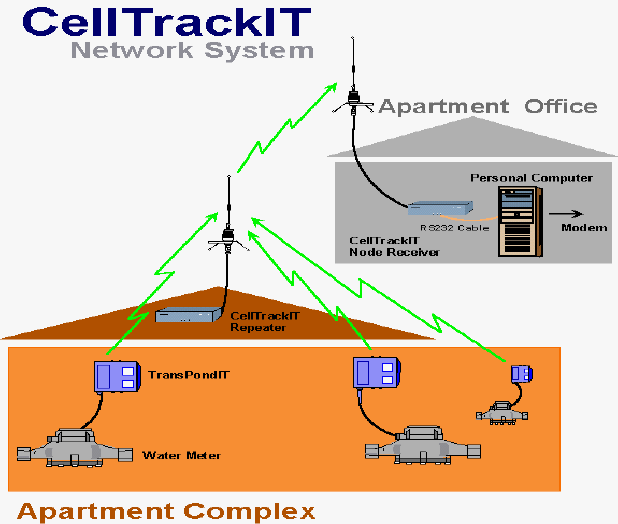
The CellTrackIT is a cost effective entry product designed to operate as a cell
network with up to 500 TransPondIT meter interface units (MIUs). It consists
of three types of functional components: the transponders, repeaters, and
node receiver unit connected to a Personal Computer (figure 1).
Figure 1. CellTrackIT Cell Network

CellTrackIT user manual Version 0.8 Page 4
Operation. The complete system is modeled as a self-contained cell
network adaptable to a variety of submetering applications. The number of
units and the terrain makeup of area covered determine the size of the
network.
The CellTrackIT is a two tier, one way radio system based on an improved
transponder technology and Spread Spectrum methodology for radio wave
propagation. The two-tier approach offers flexibility and robustness while
ensuring data integrity from the MIUs to the data collection computer within
the network. With the two-tier approach the range of the transponders is also
increased allowing for large site coverage. The system uses an open
architecture approach for data integration with existing billing systems.
The first tier comprises of transponders transmitting to a repeater. Each
repeater receives the transponder’s signals and then retransmits them to the
Node Receiver-computer combination. This back link from repeater to
computer is the second tier of the network. The data is transmitted using a
spread spectrum transmission scheme. The Node Receiver converts the
signals to ASCII data and sends it via a COMM cable to the Personal
Computer.
The node receiver is also able to directly receive Transponders. In smaller
apartment complexes a CellTrackIT with only a node receiver and no repeater
could be sufficient to cover the area. In larger apartment properties the
network will contain repeaters. Number of repeater will depend mainly on the
size of the site.
The CellTrackIT Transceiver can be set up as repeater or a node receiver.
The transceiver configures itself as a node whenever it is connected to a PC
running CellTrackIT software, via an RS232 cable. The node receiver function
is automatic upon the CellTrackIT transceiver sensing the connection and
doesn't require any further action on the part of the installer.
The data that resides within the PC can be accessed by telephone line for
remote management or locally through the on screen program.
Regulatory Notice.
Federal Communications Commission (FCC) notice
The following notice is valid for CellTrackIT transceiver when operated
as a node receiver.
NOTE: This equipment has been tested and found to comply with the limits
for a Class B digital device, pursuant to Part 15 of the FCC Rules. These
limits are designed to provide reasonable protection against harmful
interference in a residential installation. This equipment generates, uses and

CellTrackIT user manual Version 0.8 Page 5
can radiate radio frequency energy and, if not installed and used in
accordance with the instructions, may cause harmful interference to radio
communications. However, there is no guarantee that interference will not
occur in a particular installation.
If this equipment does cause harmful interference to radio or television
reception, which can be determined by turning the equipment off and on, the
user is encouraged to try to correct the interference by one or more of the
following measures:
-- Reorient or relocate the receiving antenna.
-- Increase the separation between the equipment and receiver.
-- Connect the equipment into an outlet on a circuit different
from that to which the receiver is connected.
-- Consult the dealer or an experienced radio/TV technician for
help.
WARNINGS!
• Changes or modifications not expressly approved by the manufacturer
could void the user’s authority to operate the equipment.
• The equipment is only authorized for use with the antenna and special
accessories specified in Appendix 3 of this User Manual.
• The equipment must be professionally installed. The equipment is only
authorized for use provided it is installed by qualified installers that have
received the RAMAR certified training in the design and installation of the
system.
• The CellTrackIT is solely industrial and commercial in nature, therefore it
can not be sold to the general public.
• The minimum separation between transmitter antenna and personnel is
20 cm (6 inches) to ensure that the public or the system installer are not
exposed to the radio frequency energy levels in excess of the FCC
guidelines.
Label Requirements. RAMAR complies with FCC and Underwriters
Laboratory (UL) requirements. The label attached to the CellTrackIT unit
specifies this compliance. If the label is missing, please contact RAMAR
before installing the system.
Safety Warning. The CellTrackIT unit is a self-contained product with no
serviceable user parts within. For safety reasons do not open or modify the
unit from its original usage. If the unit is defective please refer to the warranty
for disposition or call RAMAR customer service. Under no circumstances

CellTrackIT user manual Version 0.8 Page 6
should the unit be opened for inspection or troubleshooting. The power cord
receptacle is designed for standard AC power of 110-125 VAC at 10 amps. It
is strongly recommended that the power source outlet be protected against
overloads, short circuits, or surges in accordance with local and national
wiring code regulations.
Warranty. Opening the CellTrackIT voids the warranty and may result in
the user paying for all costs normally covered under warranty.

CellTrackIT user manual Version 0.8 Page 7
Planning and designing the CellTrackIT Site.
The CellTrackIT system installation consists of two phases:
PHASE 1: Planning where the network is conceptualized and designed prior
to an actual visit on site
PHASE 2: Installation phase where CellTrackIT components are installed in
the site according to the plan.
Both phases are essential in ensuring proper installation of the RAMAR
CellTrackIT system.
Basic concept is to reduce time and effort spent on site for installation by
designing the CellTrackIT system implementation before actually visiting the
site. The objective is to reduce uncertainty associated with any site by
properly planning installation and having the site prepared for installer venue.
The planning aspect of the installation is geared towards making the
connection radio-wise from the transponders to the Node Receiver by
effectively placing the node and repeaters, and determining the economical
viability of the cost per point projection.
Planning is important in that it sets the parameters, assumptions, and basic
layout of the installation.
• Planning Procedure Overview. The goal of an efficient site planning is to
minimize the number of repeaters per system while maximizing the
reception of each transponder signal. The following outlines the
procedure:
1. Gathering Data to characterize the site
2. Define the RF Range for First and Second Tiers
3. Place Node Receiver and Repeaters
4. Optimize for Network Efficiency
5. Calculate Costs per Point

CellTrackIT user manual Version 0.8 Page 8
1. Gathering Information.
It is critical to gather pertinent data to properly design the system. The data
gathered will be used for determining typical radio range. It will also be used
for determining potential locations for repeaters and node receiver.
Without the correct site characterization, the whole design process is
compromised and the installation of the CellTrackIT will be less efficient. Poor
efficiency translates to an increase to overhead costs.
The following checklist details information to be gathered
❐ Site name and address
❐ Detailed site map showing all buildings (numbered) with scale
❐ Length and width of the property
❐ Length and height of each building
❐ Outer wall construction materials
❐ Location of transponders in/on buildings
❐ Potential locations to consider for installing repeaters if:
Accessible, dry
Length of cable to externally mounted antenna at roof height < 20 feet
Permanent mains point available or can be installed
❐ Potential locations to consider for installing node receiver and computer if:
Accessible for installation, dry
Central location on the site if possible
office environment where the ambient temperatures are within the 32
to 104 degrees Fahrenheit
Length of cable to externally mounted antenna at roof height < 10 m
Permanent mains point available or can be installed
Permanent telephone connection available or can be installed
If multiple locations are suitable, indicate preference order.
And, if possible:
❐ Description of site terrain
❐ Description and location of radio obstructions not shown on map: trees,
structures, terrain
❐ Identify potential radio interference eg. proximity radio towers etc.
Scale on the map is critical. Planning methodology based on range and
distance requires a reasonable accuracy of distances or dimensions given on
the map.
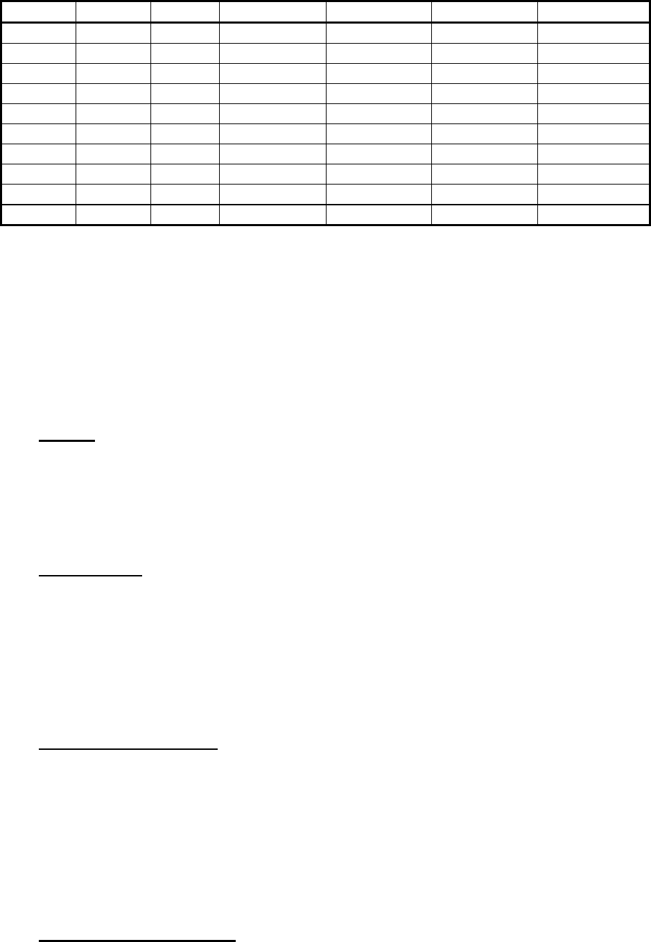
The following chart is a tool for assisting in characterizing the site, building by
building.
Building
no. Number
of Height
(floors) Loft space
suitable for Roof
construction Outer wall
construction Inner wall
construction
CellTrackIT user manual Version 0.8 Page 9
meters Repeater materials materials materials
1
2
3
4
5
6
7
8
9
10
Figure 2. Data Gathering Input Form
Planning Factors.
Certain factors influence the range of the CellTrackIT. These factors effects
are discussed and illustrated in this section. The 1st tier range is particularly
sensitive to these factors. The effects are then illustrated in a suggested
range table at the end of the section.
Height. The location of the antenna determines how well the antenna is
capable of receiving the transponder signals. As the higher the antenna the
greater number of buildings that the antenna will have unobstructed radio
path to. Normally, the higher the antenna the further the distance allowed.
See diagram at end of section. Antenna heights of less than 5 m (15 feet) in
any environment should generally be avoided.
Obstructions. Any obstacle between the transponders and the repeater
antenna will result in an attenuated signal. The obvious obstacle of the inner
and outer building walls around the transponder will be unavoidable. The best
that can be achieved is attempt to get line of sight to the exterior of the
apartment. There may be other buildings in the line of sight, or trees and
shrubs associated with the site that will reduce the radio signal.
A site with many of these unavoidable obstacles will require that the repeater
to transponder distances be reduced to compensate for signal loss.
Building Construction. Building types have to be considered when
determining the range of the installed transponders. The type of construction
will determine, among other things, how much attenuation the signal will
receive. The increased attenuation of the transponder signal due to reinforced
concrete, concrete, stucco(with metal reinforcement) construction leads to a
reduced range. Wood, particleboard or vinyl construction will allow further
range. Identify the construction type of the site buildings as part of the
information gathering process. It will be the basic information to define the
typical range for the site.
Distribution of buildings The range will be affected by the site’s density.
Buildings close together such as a courtyard setting will cause the range to be
CellTrackIT user manual Version 0.8 Page 10
reduced (obstructions). However, this could be compensated for, as the
reduced range will include more apartments and more transponders than a
less dense site.
Landscaping. Trees and shrubs when blocking the line of sight to the
transponder can cause scattering of radio signals and therefore must be
included when planning the network. The terrain plays an important part in
determining how many repeaters are needed. A reduced RF range can result
if hills and valleys cause large variations in the building heights or if hills
obscure the line of sight, resulting in an increased ratio of repeaters to
transponders.
RF Interference. Very strong external radio signals nearby, operating at the
same or near same frequencies as the CellTrackIT system can create
interference that will reduce the range to the Transponder and if present will
need to be compensated for. Potential RF interference sources are Cellular
telephone base stations at a distance of less than 800ft and Paging towers at
a distance of less than 5000ft, or other 900Mhz ISM band AMR systems that
are located close to the repeaters on the site. Many radio systems operate at
peak output during the daylight hours with diminished signal trafficking during
the night. Planning must take into account the operational hours of these
various radio systems to ensure that the system is designed for maximum
efficiency with the minimum number of repeaters.
RF self interference The minimum antenna to CellTrackIT or PC distance
should be greater than 1m. The minimum line of sight distance, repeater to
Node should be 45m.
Cable length
It should be noted that longer RF cable runs will cause the range to be
reduced, the node therefore will typically be used with a longer cable to site
the PC and in such cases will have reduced range.
Aesthetics. This is one factor that may require some negotiating with the
apartment owner or supervisor. In most cases the placing of antennas on
roofs or under eaves will not be an issue. However, it pays to first ask or to
explain the extent of change to the outward appearance of the building(s).
The supervisor or owner will definitely appreciate the consideration. Placing
the antenna inside buildings will reduce first and second tier ranges, as roof
and inner walls will attenuate radio signal.
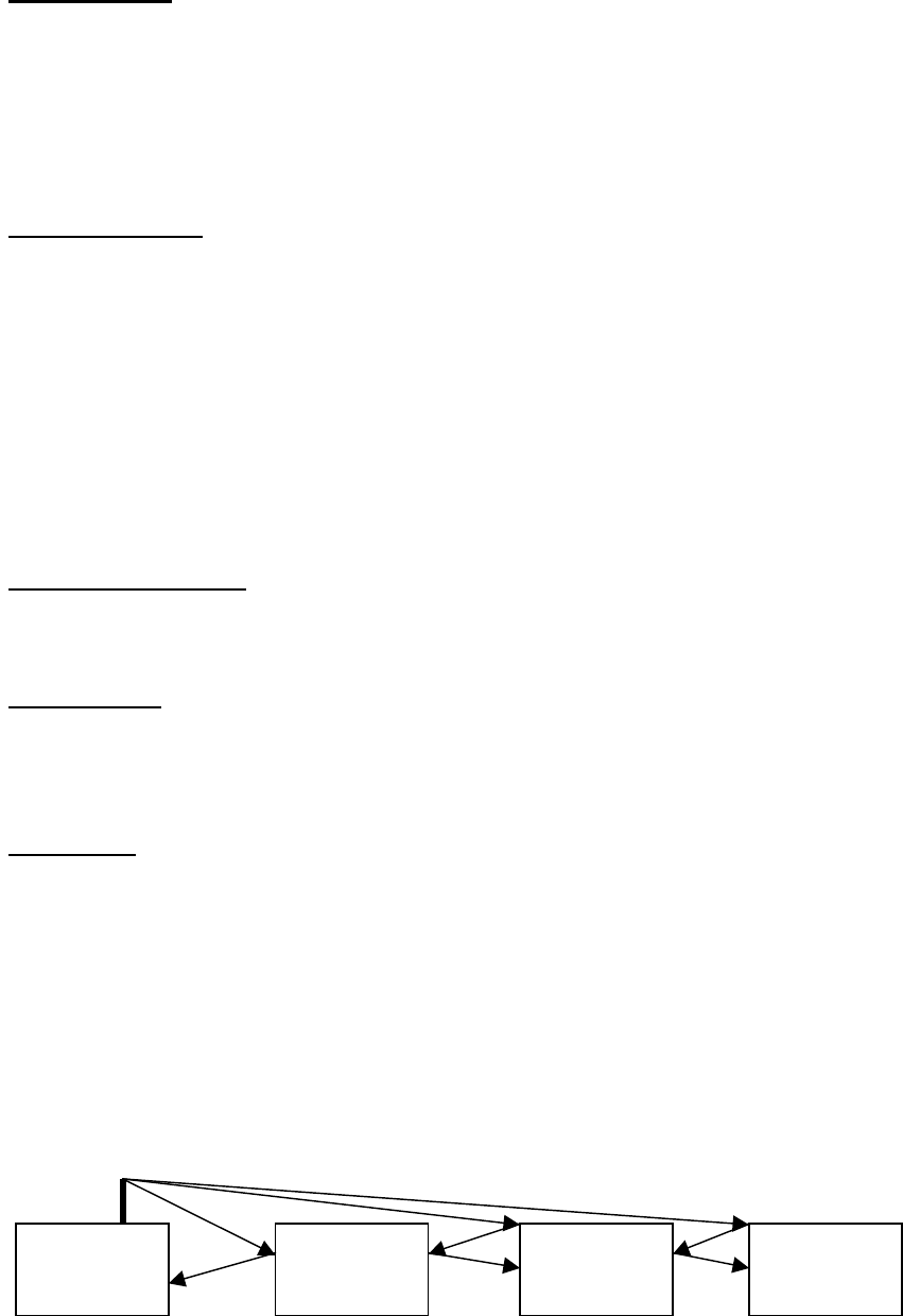
Antenna
CellTrackIT user manual Version 0.8 Page 11
Repeater site Apartment A Apartment B Apartment C
A. Illustration of roof mounted antenna, arrows indicate strongest signal path
(In reverse)
Repeater site Apartment A Apartment B Apartment C
B. Illustration of below roof mounted antenna, arrows indicate strongest signal
path (In reverse)
The advantage of high mounted antennas is shown in case A above. In case
B, for below average roof height antenna, if the buildings are of concrete or
stucco then apartment block B will have only a 50% chance of all
Transponders being read whereas the probability of all Transponders being
read in apartment B is much higher with wood or plastic clad construction.
2. Define the RF Range for first and second Tiers
RF range is defined as the maximum distance between transmitter and
receiver so that RF signal transmitted is reliably received. For planning
purpose, ranges to be used are typical ranges. It is possible that actual range
on the site is higher if RF path loss is lower than typical (e.g. transmitter line
of sight with receiver, no obstacles between transmitter and receiver).
Determine the RF range for the first tier. The first tier, which consists of
the transponder to repeater link, has a transponder signal path that must
travel through the building construction material of both inner and outer walls.
Those units that are in the lower furthermost apartments must also transmit
their signals through the various floors. The following chart provides estimated
ranges of signals that have been attenuated by the construction material of
the buildings.
Figure 3. Transponder to Repeater Ranges
Building construction Typical range
Stucco with metallic mesh frame (apartment complex) 240ft / 75 m
Reinforced concrete (courtyard apartment) 240ft / 75 m
Concrete (apartment complex) 320ft / 100 m
Wood (apartment complex) 420ft / 130 m
Plastic (apartment complex) 420ft / 130 m
Antenna
CellTrackIT user manual Version 0.8 Page 12
This typical range can be reduced according to several factors, (only use the
worst two factors), it assumes a 20ft, ½ inch diameter, cable to the antenna:
Planning factors Typical range reduction
Landscape
Dense vegetation (trees, shrubs) -5 %
Relief (hilly, ridges, valleys) -10% to 20%
Antenna location
Lower than average roof height - 30%
Inside building - 30%
RF environment
Paging transmitter within 1500m
(If antenna inside building) -20%
-10%
60ft cable to antenna -25%
First tier range for a site will be determined by reducing typical range of the
total of the planning factor reductions associated with this site.
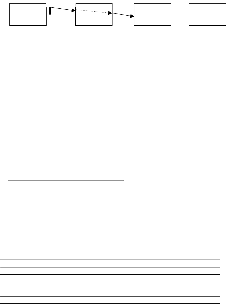
Determining the RF Range for the Second Tier. The second tier ranges,
which consists of repeater to node receiver link, are influenced more by
landscape than by construction materials. Obstacles such as trees, tall
buildings, and terrain contours contribute to the signal path loss experienced
by each retransmitted transponder signal. The following charts illustrates
range based on two typical deployments.
Line of sight
Both antennas at average roof height
typical range 5000ft
Not line of sight
one antenna at average roof height
other antenna at 5m height externally wall mounted
and obscured behind 1 building
typical range 1600ft

CellTrackIT user manual Version 0.8 Page 13
Figure 5. Repeater to Node Receiver Ranges
3. Determine location of Node Receiver and Repeaters
Node Location. Network designing on the site map requires that the designer
first identify the node receiver location. Ideally, the node receiver will be
centrally placed on the site. This would allow for more site area coverage
which will ensure more transponders will be within range. However, in some
cases placing the node receiver in a central location may not be feasible.
Additionally, the only location available may be the clubhouse or the main
office of which neither may be centrally located. The designer then must be
flexible whenever placing the node receiver. Regardless of choice, the node
receiver possible locations need to be identified first. When placing the node
receiver consider where the Personal Computer will be located since it is
attached directly to the node receiver.
Node receiver location specification:
Accessible for installation, dry
Central location on the site if possible
Office environment, ambient temperatures within 32 °F to 104 °F
Length of cable to externally mounted antenna at roof height < 60 feet
Permanent mains point available or can be installed
Permanent dedicated telephone connection available or can be installed
The node receiver is able to receive both transponders and repeaters, by
alternating automatically between these 2 modes. Therefore, the node
receiver can be used as a transponder receiver.
Once node is located on the site map, draw a circle with node location as the
center and 75% of the first tier range determined in stage 2 for this site as the
radius. Reason for using only 75% of the first tier range, is the assumption to
use a 60 feet antenna cable, which introduces more attenuation than a 20
feet one used for repeaters. If the node antenna cable can be 20 feet long,
use full range.
When drawing the circle, verify the scale on the map. Incorrect scale will lead
to wrong distance, therefore wrong planning. Transponders could be out of
range.

CellTrackIT user manual Version 0.8 Page 14
The node will receive all transponders inside the circle. Transponders outside
the circle will need repeaters to be received.
Repeater Location.
Repeaters must be located in attic/loft space in buildings.
Repeater location specification:
Accessible, dry
Length of cable to externally mounted antenna at roof height < 20 feet
Permanent mains point available or can be installed
Determining Repeater Location.
Once the transponders received by the node receiver are determined,
repeaters must be added to cover remaining parts of the site. It is then a
matter of placing circles on the map, with typical range determined for the site
as a radius, to have all the transponders within the range of at least one
repeater. This can be achieved by using a compass, placing the pin on a
possible repeater location and drawing a circle. Check then if some
transponders have been left outside the circle.
The easiest way is probably to cut circles at the right scale in transparent or
thin paper, locating the center with a cross, then place and reposition the
circles on the map until all the transponders are within a repeater range.
When repositioning ensure that the buildings are still maintained within the RF
circle of each repeater. When doing the RF circles take the liberty to
reposition the repeaters to cover areas more efficiently. In some cases, by
moving two repeaters slightly, a third repeater can be eliminated.
When all the repeaters are located, mark the center and remove the paper
circles. Then draw final circles with the compass on the map.
Sketch with only a circle around the node.
CellTrackIT user manual Version 0.8 Page 15
NOTE: A transponder signal may repeated by several repeaters without
diminishing the efficiency of the network. The system is designed to handle
simultaneous reads.
4. Optimize for Network Efficiency
It is critical to verify at this stage that repeaters can actually be placed where
they have been located on the map. Checking in information gathered or
calling the site manager would be helpful at this stage to avoid having to
cancel the plan at arrival on site for installation. This includes access to attic
space or utility room, possibility to use a 20 feet cable between the repeater
and the antenna and possibility to install a power line (115 V AC).
Optimizing goal is to reduce the number of repeaters to be installed on the
site by reducing overlapping or moving repeaters to have a better coverage.
This is achieved by moving circles around the map.
While optimizing the design it is recommended to check furthermost
transponders to the repeaters (closer to the circle lines). They are the most
critical. It is recommended to check for factors that could reduce the range
(buildings, trees, height compared with repeater antenna). Refer to planning
factors table (figure 4).
It is also recommended to check lines of sight to verify the number and the
nature of obstacles between Transponders and Repeaters. For example 2
concrete buildings between a Transponder and a repeater will induce a high
risk not to receive the transponder.
NOTE: The idea is to eliminate repeaters while maintaining adequate
coverage of the transponder points.
Determining Cost Analysis.
The cost of the CellTrackIT system can be determined once the placement of
the repeaters is completed on the site map. Our sample in Figure 7 shows
that two repeaters were needed for the entire system to function properly.
Figuring total cost per point is a matter of identifying the various costs
associated with a CellTrackIT System installation.
CellTrackIT System Cost. The total CellTrackIT System cost is directly tied
to the number of repeaters used within the site. When designing the network
it becomes important that the number of CellTrackIT transceivers be
minimized.
The CellTrackIT transceiver antennas will need a bracket or possibly a metal
pipe for its installation. Depending on how each repeater is installed, the
antennas may also need brackets or metal pipe for setup.

CellTrackIT user manual Version 0.8 Page 16
The antennas also should be wired against lightning strikes, which would
require grounding wire.
Electrical Costs. The cost of installing power conduit in attics or along walls
per repeater has to be factored into the cost per point determination. The
installation of the AC power must comply with standard building codes.
Normally, a licensed electrician will be required to install the electrical wiring.
If the CellTrackIT PC is being located in a secluded place then a power
source will be needed for both the PC and the node receiver.
Telephone Costs. For each CellTrackIT PC a dedicated and direct
telephone line will be required. The cost of installing the line and the various
hookup charges need to be considered. The monthly cost of renting the
telephone line needs to be included in the operating costs of the site and not
in determining installation cost per point.
Man-Hour Costs. Included in this is the hours spent in planning and
coordinating the site or any additional hours associated with the installation
process.
Figuring Costs. Figuring cost per points is as simple as adding the costs
and dividing by the number of apartment units at the site location. Once the
cost per point is determined then a decision to proceed with the installation
can be made.
Site preparation
The objective of site preparation is to reduce the time spent on site to
physically install the components of a CellTrackIT system. Making sure every
person involved and every piece of equipment are available, is critical to a
successful implementation.
The result of the planning phase is a list of locations where repeaters, the
node receiver and the PC have to be installed. Verifying the plan is applicable
will secure an efficient installation. Here again, the easiest way is to phone
the site owner or site maintenance manager and review the plan with him.
Site preparation is a critical element of the CellTrackIT installation
procedures. There are tasks that must be accomplished prior to installing any
component at the apartment site.
CellTrackIT user manual Version 0.8 Page 17
• The installer needs to procure all parts not included in the CellTrackIT
system. This means that a certain amount of lead-time is needed to
ensure that parts arrive prior to the actual on site installation.
• External subcontract work such as the AC power conduit installation for
the repeaters and the telephone line installation for the PC needs to be
scheduled and completed.
• Proper tools need to be identified so that there will not be on site delays
due to improper or missing tools. In particular, determine how the
repeaters and the antennas will be installed on/in the apartment roofs. In
some cases, special ladders will be needed that can reach more then two
stories.
• When installing the water meters with attached transponders track serial
numbers to apartment address or account numbers to minimize confusion
later on. It is very easy to mistake a read from one apartment when it
belongs to another due to wrong record keeping.
Before proceeding to the installation, it is recommended to check the
following items:
❐ Equipment, tools and installation materials are available.
❐ Site owner and site maintenance manager are aware and agree with
installation operations that will be performed.
❐ All the locations where repeaters and node are planned to be installed will
be easily accessible.
❐ Power and phone lines have been installed or their installation is planned to
match with the requirement to leave the site with a fully installed CellTrackIT
system.
❐ All the transponders will be installed before completion of the CellTrackIT
installation
❐ A matching list of transponders ID and meter (or apartment) number is
available.
Any missing item in that list will imply to be addressed on site. That could
delay CellTrackIT installation.
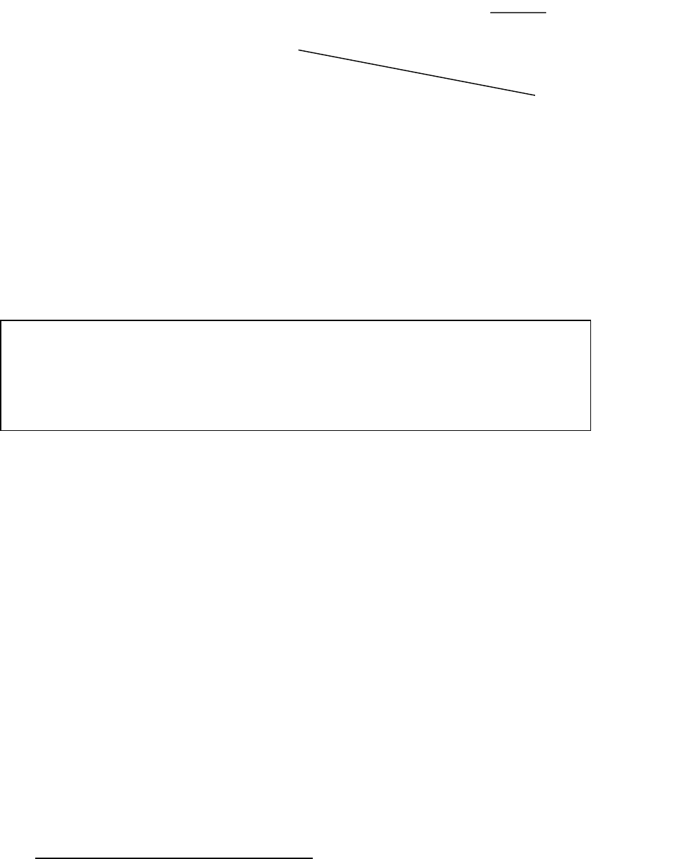
Installing the CellTrackIT System.
Installing the Node Receiver. Installing the Node Receiver consist of
plugging a CellTrackIT transceiver to a 115 VAC power outlet and connecting
the RS232 cable between the COMMS Port of the CellTrackIT unit and the
PC. The Com1 on the PC is normally where the cable is connected. Once
this is done, then the antenna with the associated coaxial wiring is installed.
CellTrackIT user manual Version 0.8 Page 18
Figure 12. Node Receiver Connections.
Installing the Node Receiver Antenna. The coaxial cable that connects the
antenna to the Node Receiver is in the Node accessories box. It is 60 feet
long. One end of the cable requires an N type Male connector that is then
screwed on the antenna. The other end requires a male TNC connector that
attaches to the RX/TX connection on the CellTrackIT unit. Appendix 2 covers
in detail the cable assembly and antenna mounting procedures.
Important: Do not handle the antenna when connected to a powered
CellTrackIT transceiver, or make sure the minimum separation between
antenna and personnel is 20 cm (6 inches). Locate the antenna in a manner
that ensures that the public will not be exposed within this separation distance
for purpose of FCC RF exposure compliance.
The Node Receiver antenna should be installed so that it clears the roof and
isn't obstructed by any part of the building. The antenna should be at least 6
inches away from any metal object along its length and tip. The standard
practice is to attach a 1-inch x 10 feet conduit pipe (normally found at home
improvement stores) to the roof element. If the antenna pole needs to be
longer, use a thicker pipe to compensate for wind velocity or add guide wires
to secure the pole (Check local ordinances for compliance requirements). The
antenna with its attachment bracket is then connected to the pole. Most CB
radio and electronics stores have mounting brackets for mounting antennas
and antenna poles. Run the coaxial cable down the inside of the pipe if
possible.
The coaxial cable that comes out from the end of the antenna pole will need
to be placed in conduit (PVC pipe) or attached to the wall. Avoid damaging
the coaxial cable when attaching it to the wall. Make sure that the attachment
nails do not puncture the black plastic covering or any portion of the cable.
The antenna that is provided with the CellTrackIT transceiver has been FCC
compliance certified and approved and can't be replaced with any other
antenna. Contact RAMAR Technical Support if the antenna needs replacing
or is not available at the time of installation.
• Verifying Node Receiver Operation. Once the node receiver is
installed and the connections are completed check the two red LEDs for
activity. The POWER LED should be on while the DATA LED will be
COMMS
Port
VAC Power

CellTrackIT user manual Version 0.8 Page 19
flickering in an on-off mode. If either malfunction check the AC power
source for the POWER LED and the antenna for the DATA LED. The best
approach would be to replace the CellTrackIT transceiver with another. If
that doesn’t solve the problem then check the power source by simply
turning the PC on and checking operation. The antenna check will require
attaching the HandTrackIT to determine if transponder transmissions are
being received.
Configuring the Node Receiver. The CellTrackIT transceiver will
automatically configure itself to function in a receiver capacity whenever an
RS232 cable is connected to it. The node receiver will be ready for use when
the power cord is plugged into an AC source and the RS232 cable is attached
between the receiver and the PC. The installer will, however, have to provide
aliases for each repeater for identifying the repeaters during maintenance..
Configuring the CellTrackIT PC.
• Hardware. Once the PC has power, plug in the telephone line into
the LINE in jack on the modem card. The system should already have
Windows software installed. Test the phone line by having someone dial in
from their computer once the CellTrackIT system has been installed and is
operational.
The connection between the PC and the CellTrackIT unit will require an
RS232 cable with 9 pin male connector on one end and a 9 pin female
connector on the other. This cable is included in the Node accessories
box.
• Software. Refer to CellTrackIT software installation manual.
Installing the Repeater. The CellTrackIT transceiver is designed to be
installed in lofts or roof spaces and not for external installation. When
installing the repeater write down the 10 digit serial number and building it is
associated with. This information will later be used for configuring the
network.
The unit must be connected to 115 V AC for it to operate correctly. The AC
power should include ground for proper repeater operation. When installing
the power source, ensure that applicable building codes are adhered to.
The repeater accessories box includes a 20 feet of coaxial cable for antenna
installation. The antenna should be installed just under the roof eaves using
the recommended antenna-mounting bracket (see Appendix 2). As in the
Node Receiver antenna, the repeater antenna can't be substituted for a
different kind. When placing the antenna, make sure that it is located on the
side of the building closest to the transponders it is servicing.

CellTrackIT user manual Version 0.8 Page 20
Figure 15. Proper Mounting of CellTrackIT Repeater.
Plug in the power cord and attach the antenna coaxial cable with the male
TNC connector end to the RX/TX TNC hookup. Do not connect the antenna
to the RX connector. Only the RX/TX connector must be used. The other
end of the cable should have a male N Type connector that screws to the
antenna (Appendix 2).
Figure 16. CellTrackIT Repeater Connections.
Both the Node Receiver and repeater antenna connections at the N Type end
should be wrapped in water proof tape to prevent corrosion due to water
seepage (ACE Rubber Splicing Tape --ACE 30986).
• Verifying Repeater Operation. Once the repeater is installed in the
attic and the connections are completed check the two red LEDs for
activity. The POWER LED should be on while the DATA LED will be
flickering in an on-off mode. This flickering shows some Transponder
signals are received.
Trouble shooting
Observe LED lights. The repeater will not transmit if power isn’t applied to it or
if it doesn’t receive any signals from the transponders.
CellTrackIT user manual Version 0.8 Page 21
The POWER LED should be on. Check the power cord is properly connected.
Check the power source by simply plugging in any AC device (plug in light or
power drill) and checking operation.
If the power source is working, try a new power cord or replace the
CellTrackIT transceiver.
The DATA LED should be flickering in an on-off mode. Check that the
antenna cable is properly connected. Then check the antenna. The antenna
check will require attaching the HandTrackIT to determine if transponder
transmissions are being received.
If transponder transmissions are received, replace the CellTrackIT
transceiver.
CellTrackIT user manual Version 0.8 Page 22
GLOSSARY

CellTrackIT user manual Version 0.8 Page 23
Recommended Parts List & Suppliers
Appendix 3
The following parts (with asterisk) have been determined to comply with the
necessary FCC 15 Rule and have been approved by RAMAR for use in the
CellTrackIT system. Use of any other component may result in an FCC
violation and could result in the CellTrackIT system being permanently
disconnected or its operation temporarily suspended. Using components
other then those specified by RAMAR voids the system warranty.
All the basic components needed to install a CellTrackIT system are
contained in CellTrackIT accessories boxes.
PART PART NO. REMARKS
Antenna* B8965C Antenex 1-800-323-3757
Antenna Base* MBC800 Antenex 1-800-323-3757
Antenna Mount Right angle iron appr. 11” X 8.5” X 1”
Antenna Pole 1.5” X 10” Conduit Pipe
Antenna Pole Mount Check local electronics store for kit
Copper wire Standard lightning arresting wire
Copper rod Standard lightning rod
Lesson Plan For CellTrackIT Installation Training
Appendix 4
CellTrackIT user manual Version 0.8 Page 24