Bluecard Software Technology BLUECARD900 UHF Long Range Reader User Manual
Bluecard software Technology Co.Ltd. UHF Long Range Reader
User manual
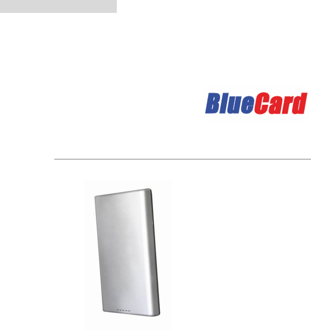
UHF Long Range Reader User Manual
902-928MHz
Model: BU-900R-K
American Standard
Please read this manual carefully, before starting to operate the reader.
ENGLISH
2
Table of Contents
1. INTRODUCTION....................................................................................................................3
1.1. Introduction ...............................................................................................................3
1.2. Audience.....................................................................................................................3
1.3. Reading Guide ..........................................................................................................3
1.4. Reader Description..................................................................................................3
2. CONTROL PANEL.................................................................................................................4
2.1. Power Supply ............................................................................................................4
2.2. Indicator......................................................................................................................4
2.3. Communications ......................................................................................................4
2.3.1. General Input / Output.........................................................................................4
2.3.2. Ethernet Data Transfer........................................................................................4
Communicate between reader to software via Ethernet RJ45 cable (it is based
on TCP/IP protocols)...........................................................................................................4
2.4. Adjust Reading Ranges..........................................................................................5
2.5. Switch Board.............................................................................................................5
2.5.1. Trigger Reading ....................................................................................................5
2.5.2. Command Mode....................................................................................................6
2.5.3. Turn On/Off 2.4G...................................................................................................6
3. READING INSTALLTAION...................................................................................................6
4. CHOOSING & INSTALLING TAGS ....................................................................................7
4.1. Tag Model...................................................................................................................7
4.2. Reader & EPC Card Alignment.............................................................................8
5. TROUBLSHOTTING AND MAINTENANCE .....................................................................8
5.1. Troubleshooting .......................................................................................................8
5.2. Maintenance ..............................................................................................................8
6. TECHNICAL SPECIFICATIONS .........................................................................................9
3
1. INTRODUCTION
1.1. Introduction
BU-900R-K UHF Long Range RFID product is one of the significant RFID products designed
by BlueCard. It is a reader compliant with EPC Gen2 standard, which is widely used in the
fields such as Vehicle Parking Management System, Time & Attendance System, Personnel
Access Control Management, and Stock Management System.
Advantages:
- Reading distance is up to 10 meters with passive card..
- Integrated antenna
- Wiegand output specialized for Access Control Management System.
- GOIP for external device control
1.2. Audience
This document is used only by authorized BU-900R-K distributors, installation engineers. This
manual provides you the instructions of testing, setting, installing of BU-900R-K, please read
the manual carefully before start to use the reader.
1.3. Reading Guide
This document is a detail instruction on BU-900R-K, which includes hardware description, tag
instructions, power supply, host computer instruction, how to test and install the reader,
troubleshooting, reader’s specifications and definition for the pins.
1.4. Reader Description
Bluecard BU-900R-K UHF reader is long reading distance UHF RFID reader with attached
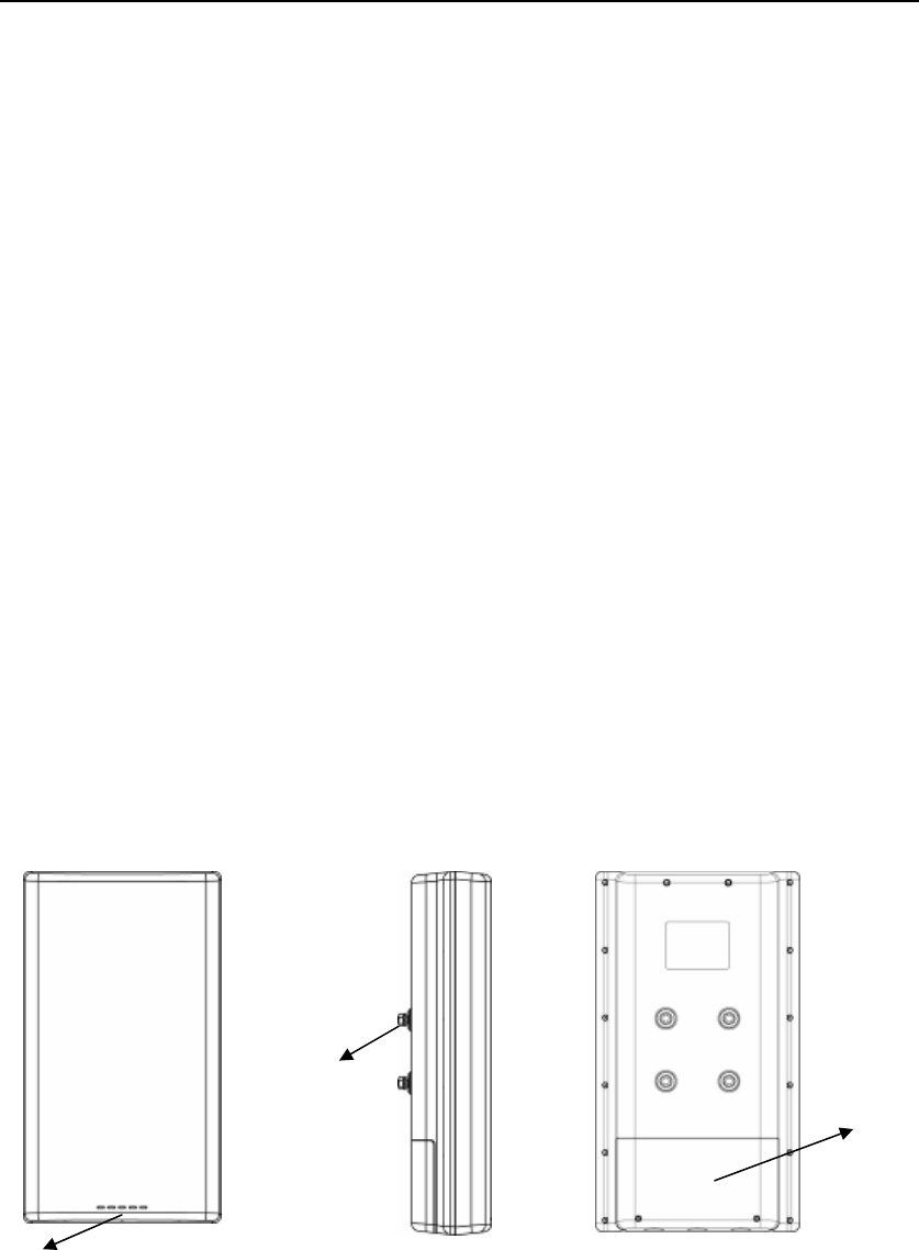
antenna. BU-900R-K has five LED light to indicate the reader status. Please refer to the
following figure for the BU-900R-K detail appearance.
Front View Side View Back View
LED
Stud, Gasket,
and Nuts for
Mounting
Removable Cover
4
2. CONTROL PANEL
2.1. Power Supply
BU-900R-K needs a dedicated power supply at the site in all the time. The acceptable power
supply is 12V DC. Please use the AC-DV adapter supplied by the manufacturer.
INPUT OUTPUT
Voltage/V Power/Hz Voltage/V Ampere/A
100~240 47~63 12 5
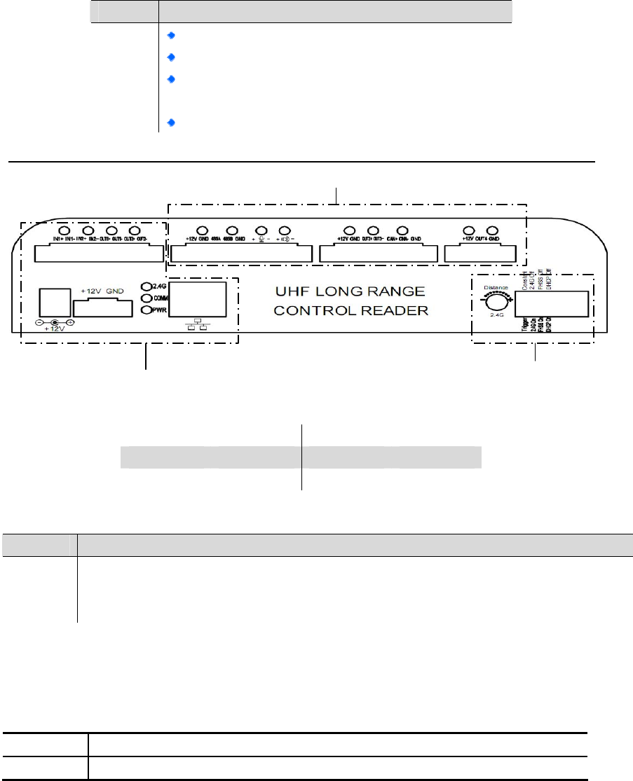
2.2. Indicator
Indicator Definitions
INPUT Under trigger mode, the LED is flashing when reader receive signal from extra devices.
COMM The LED is flashing when communicate with host computer
PWR The LED is constant on when switch power on
2.3. Communications
2.3.1. General Input / Output
The function allows you to receive extra devices’ signal, such as loop detector and optical
sensors (for more details please refer to page 6 Trigger Reading).
INPUT when the external device sends 5~48V will trigger the reader make readings
OUTPUT can only driver the device less than AC110V / DC60V, less than 1A
2.3.2. Ethernet Data Transfer
Communicate between reader to software via Ethernet RJ45 cable (it is based on TCP/IP
protocols).
Color Definition
BLUE
Flash once: the power has been turned on
Flash & Beep once for each reading
Four Blue LED stays on means the environment
is very bad situations
RED Constant On: reader standby with power supply
Other Reserved Conection Ports

5
2.4. Adjust Reading Ranges
This function is for active tag only. A standard BU-900R-K reader can work with both
ECOMPUTER G2 C1 passive tags and active tags. With a passive tag, its reading range can
be up to 10m, depending on tags and/or change the output power of the antenna. Its reading
distances are more flexible on active tags. As there are more tag models selectable.
Each of our major active tag models has several sub-models, shown by suffix e.g. -12, -40 and
-70. These sub-models enable a reader to have variable minimum and maximum adjustable
ranges. For example, to present both BGC-S-12 and BGC-S-70 tags in front of a BU-900R-K,
the min. adjustable range for BGC-S-12, should be around 3-5m, while the min. adjustable
range for BGC-S-40 can reach 20-30m. The maximum adjustable range on a -12 tag can be
12m, while on a -40 tag, it can make 40m and more.
On the same tag, clients can still set different reading ranges by rotating the embedded
potentiometer in the reader.
Clients can use a small screwdriver to rotate the potentiometer clockwise or counter clockwise,
accordingly the reading range becomes longer or shorter. At the adjustable extreme, you can
hear a low spring-like sound, after that, further rotation in the same direction would not change
the reading range any more. There are around five valid rounds between the minimum and
maximum adjustable position.
2.5. Switch Board
BU-900R-K can work on three reading modes. By factory default, when a BU-900R-K is
connected to the appropriate power supply, it will begin to read tags continuously. Also the
reader can be triggered to read by a loop detector or infrared detector.
Users can switch between constant and trigger mode easily on the reader’s panel.
Notes: after switching the reading mode, the reader should restart to make the change
takes effect.
2.5.1. Trigger Reading
To enable this mode, the reader needs to be wired to a trigger (typically a loop detector or
infrared detector) via its general input. For testing purposes, you may short IN+ with IN-, which
will generate a valid trigger signal. Notes: when trigger signals received, BU-900R-K will
continue to make reading for 2 seconds.
6
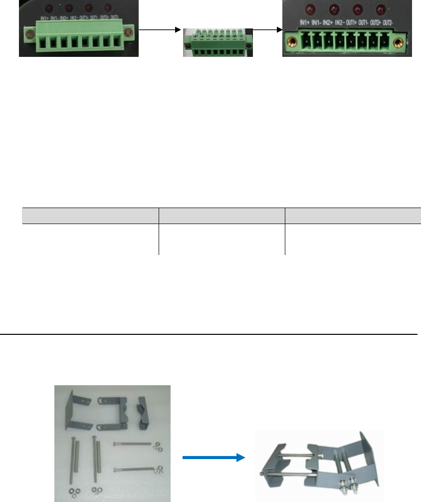
Users can pull out the terminal block on the reader’s interfaces for easy wiring with external
devices, and then put it back to complete connection with the reader (shown below).
2.5.2. Command Mode
In this mode, BU-900R-K will remain on standby until it receives a command from
COMPUTER. For example, the reader will start to make readings when the COMPUTER sent
a read command to a BU-900R-K, meanwhile, the reader will return a confirm data to
computer as confirmation. The command mode is to facilitate clients to integrate the reader.
When a reader is working, it should emit LED and audio signals according to its operation
status.
Turn On/Off
Notes: after the switch, please restart the reader.
3. READING INSTALLTAION
A BU-900R-K can be fixed in sites in any way they see fit. Installers are recommended to order
a standard pole mounted bracket from the manufacturer to install the reader. Below is our
mounted bracket.
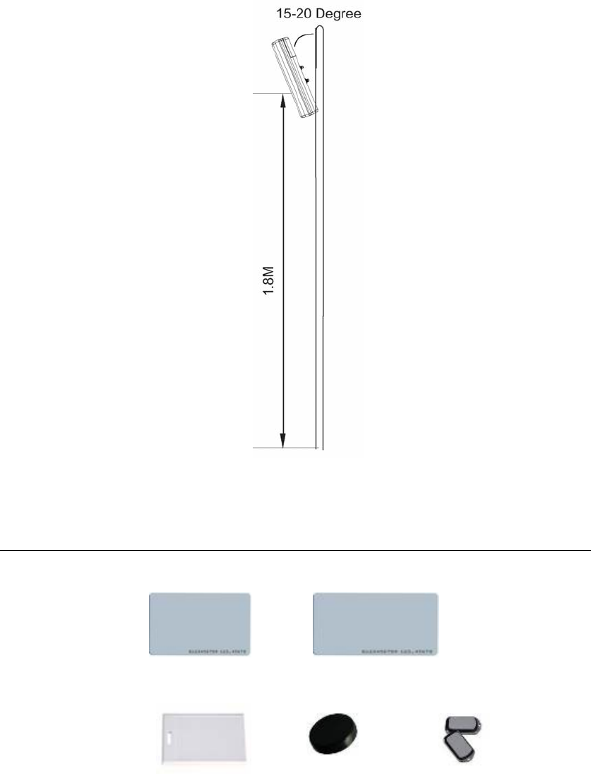
The reader can be mounted on either a pole or wall. The reader is equipped with a linear
horizontal antenna with limited readable angle. It should be installed at a suitable height and
angle towards the ground, so as to give the optimal performance.
Reader Operation Status LED Signals Audio Signals
Standby Red Light Constant On No
Reading Blue Light Keeps Flash Beep Once for Each Read
Pull out terminal blocks
7
A series of factors can affect the reader installation height and angles, including the reading
distance, width of the lane, types of vehicles, etc. The figure below shows a typical installation
for your reference.
4. CHOOSING & INSTALLING TAGS
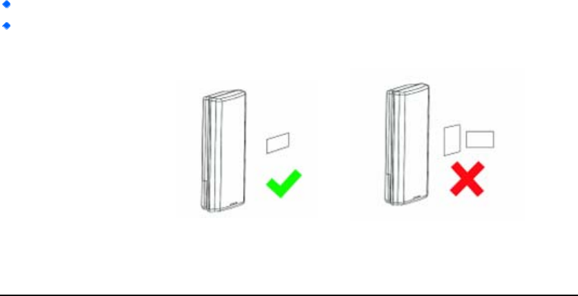
4.1. Tag Model
Passive Card (EPC Standard)
BMC-G2C-01 BMC-G2C-04
Active Tags
BGC-S BGC-04 BGC-K
8
4.2. Reader & EPC Card Alignment
The following criteria must be satisfied to achieve the optimum read reliability:
Polarization of the tag and BU-900R-K must be aligned in the same direction.
The installed tag must be in a direct, unobstructed line of sight to BU-900R-K. All the
materials reduce the RF signal. Metal and water can cause the significant problem by
reflect and absorb single.
Polarization
correct tag position incorrect tag position
5. TROUBLSHOTTING AND MAINTENANCE
5.1. Troubleshooting
Q: Why the blue LED on my reader never flash and the reader cannot read tags?
A: Please check with its reading mode settings. Only at the constant mode, the reader will
read tags automatically. At the trigger mode, however, the reader should receive a triggering
signal to start reading.
Q: My reader can hardly read a tag or the distance shorter than expected, what is the
reason?
A: The reader is equipped with a linear horizontal polarization antenna. So tags should be
placed in a way where its polarization direction is in line with that of the reader’s antenna. If
you consider the reading ranges not so well on a tag, please rotate the tag by 90º and try
again.
Also in one of following situations, the reading distance can be shortened even there is no
problem on the reader: tags are close to or have direct contact with human body, metal screen,
or liquid obstruct between reader and tags.
Q: Why the reading distance of my reader on windshield tags is so short in the open
air?
A: Windshield tags, as the name suggested, should be attached on window so as to get
optimal reading effects. For simulation, you can fix a tag on a piece of glass with crystal tapes,
and try again with the reader.
5.2. Maintenance
There are a few tips to get the optimal performance out of the reader.
9
1. Always use the power adaptor provided by the manufacturer, or consult the supplier for a
compliant power adaptor from a third source.
2. DO NOT disassemble the reader. If there is any problem on the device, please return the
supplier for repairing.
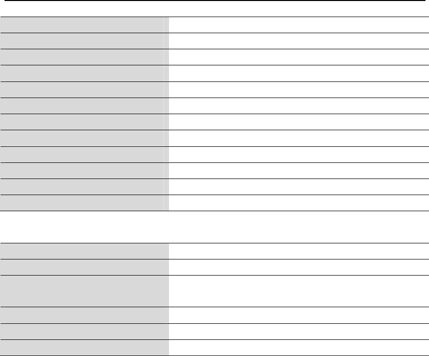
6. TECHNICAL SPECIFICATIONS
Reader Specifications
Power Supply 12V/ DC,5A (current)
Communication Interface Wiegand (26/34); RS232
Serial Port Maximum Data Rate 4800bps, 9600bps, 57600bps, 115200bps
Wiegand Data Rate Pulse width time is 100us, pulse intervals time is 1.0ms
GPIO 1 photo coupler input and output
Dimension 460×260×110mm
Weight 3 Kg
Operating Temperature -20 ºC ~+65 ºC
Storage Temperature -40 ºC ~+85 ºC
Humidity 10-95%
Environmental Sealing IP65, DC ground lightening proof
Housing FRP + stain resistant aluminum
RFID Specifications
Frequency Range 902-928MHz
Operating Mode FHSS or Fixed Frequency
Reading Range Passive tag: up to 10m
Active Tag: depending on tags & adjustment
Operation Mode Constant, trigger, command
Moving Tag Detection ≤40Km/h
Number of Antenna 1 integrated, linear horizontal

10
FCC Statement:
Any changes or modifications to this unit not expressly approved by the party responsible for
compliance could void the user’s authority to operate the equipment.
This device complies with part 15 of the FCC Rules. Operation is subject to the following two
conditions:
(1) This device may not cause harmful interference, and (2) this device must accept any
interference received, including interference that may cause undesired operation.
Note: This equipment has been tested and found to comply with the limits for a Class B digital
device, pursuant to part 15 of the FCC Rules. These limits are designed to provide reasonable
protection against harmful interference in a residential installation. This equipment generates, uses
and can radiate radio frequency energy and, if not installed and used in accordance with the
instructions, may cause harmful interference to radio communications. However, there is no
guarantee that interference will not occur in a particular installation. If this equipment does cause
harmful interference to radio or television reception, which can be determined by turning the
equipment off and on, the user is encouraged to try to correct the interference by one or more of
the following measures:
—Reorient or relocate the receiving antenna.
—Increase the separation between the equipment and receiver.
—Connect the equipment into an outlet on a circuit different from that to which the receiver is
connected.
—Consult the dealer or an experienced radio/TV technician for help.
RF Exposure Statements:
To comply with RF exposure requirements, antennas that are operating near users at stand-alone
desktop of similar configurations must operate with a minimum separation distance of 20cm from
all persons.
RFID devices for use through the EEA have the following restrictions:
• Maximum radiated transmit power of 2W ERP.
Statement of Compliance:
Bluecard software Technology Co., Ltd. hereby, declares that this device is in compliance with the
essential requirements and other relevant provisions of Directive 1999/5/EC.