Bosch Security Systems DCNWAP Wireless Access Point User Manual Part 1
Bosch Security System BV Wireless Access Point Part 1
Contents
- 1. User Manual Part 1
- 2. User Manual Part 2
User Manual Part 1
Installation and User Instructions
Wireless discussion systemen
DCN Wireless

Bosch Security Systems | 2007-02 | 9922 141 70691 en
DCN Wireless | Installation and User Instructions | Important Safeguards en | 3
Important Safeguards
Before you install or operate the DCN Wireless digital
congress network, you must read the Important Safety
Instructions. The Important Safety Instructions are
supplied together with the central control unit.

Bosch Security Systems | 2007-02 | 9922 141 70691 en
DCN Wireless | Installation and User Instructions | Disclaimers en | 4
Disclaimers
CobraNet is a trademark of Peak Audio — a division of
Cirrus Logic, Inc. — in the United States and/or other
countries.
Bosch Security Systems | 2007-02 | 9922 141 70691 en
DCN Wireless | Installation and User Instructions | About this manual en | 5
About this manual
Function
The Installation and User Instructions gives the
installers and the operators the necessary data to install,
configure and operate a basic DCN Wireless Discussion
System.
When you want to make a more advanced DCN
Wireless Discussion System, you also need information
from the DCN Next Generation Installation and User
Instructions.
The product index (refer to appendix B) tells you where
you can find more data about devices that can be
connected to DCN Wireless.
Digital version
The Installation and User Instructions is available as a
digital file (Portable Document File, PDF).
When the PDF refers you to a location that contains
more data, you can click the text to go there. The text
contains hyperlinks.
Admonitions and notes
The Installation and User Instructions uses admonitions
and notes. The admonition gives the effect if you do not
obey the instructions. These are the types:
•Caution
If you do not obey the caution, you can cause
damage to the equipment.
•Warning
If you do not obey the warning, you can cause
personal injury or death.
Signs
The Installation and User Instructions shows each
admonition with a sign. The sign shows the effect if you
do not obey the instruction.
The sign that is shown along with a note gives more
data about the note itself.
Admonition
General sign for cautions and warnings.
Admonition
Risk of electric shock.
Admonition
Risk of electro-static discharges (refer to the
section ’Electro-static discharges’).
Note
General sign for notes.
Note
Refer to another information source.
Bosch Security Systems | 2007-02 | 9922 141 70691 en
DCN Wireless | Installation and User Instructions | About this manual en | 6
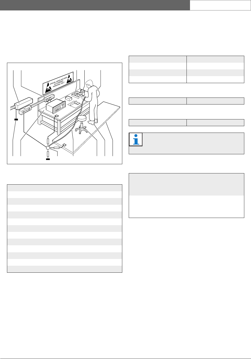
Electro-static discharges
Electro-static discharges can damage electric
components. You must take measures to prevent
electro-static discharges when you touch PCBs (refer to
figure 1).
Conversion tables
Length, mass and temperature are in SI units. Refer to
the data below to change SI units to imperial units.
figure 1: ESD prevention
table 1: ESD prevention
No. Description
1 Safety isolating transformer
2Distribution supply box
3 Conductive compartment trays
4Electro-static voltage sensor
5 Cotton overall
6Conductive floor mat
7 Conductive boots/heel grounding protectors
8Conductive stool
9 Strap (resistance 0.5 to 1.0 MΩ)
10 Common reference point
11 Conductive bench top
12 Supply ground
312
12 11 10 9 8 7 6
4 5
table 2: Conversion of units of length
1 in = 25.4 mm 1 mm = 0.03937 in
1 in = 2.54 cm 1 cm = 0.3937 in
1 ft = 0.3048 m 1 m = 3.281 ft
1 mi = 1.609 km 1 km = 0.622 mi
table 3: Conversion of units of mass
1 lb = 0.4536 kg 1 kg = 2.2046 lb
table 4: Conversion of units of pressure
1 psi = 68.95 hPa 1 hPa = 0.0145 psi
Note
1 hPa = 1 mbar.
table 5: Conversion of units of temperature
°F9
5
--- °C32+⋅=
°C5
9
--- °F32–()⋅=

Bosch Security Systems | 2007-02 | 9922 141 70691 en
DCN Wireless | Installation and User Instructions | Table of Contents en | 7
Table of Contents
Important Safeguards ..................................................................................................................................................3
Disclaimers ......................................................................................................................................................................4
About this manual .........................................................................................................................................................5
Table of Contents ..........................................................................................................................................................7
Section 1 - System Design and Planning............................................................................................................. 11
1. Wireless network design ........................................................................................................................................................... 12
1.1 Introduction ............................................................................................................................................................................ 12
1.2 Limits ....................................................................................................................................................................................... 12
1.3 Frequency band .................................................................................................................................................................... 12
2. DCN design .................................................................................................................................................................................. 14
2.1 Introduction ............................................................................................................................................................................ 14
2.2 Calculation tool ..................................................................................................................................................................... 14
2.3 Concepts ............................................................................................................................................................................... 14
2.4 Limits ....................................................................................................................................................................................... 14
2.5 Control capacity ................................................................................................................................................................... 15
2.6 Power capacity ..................................................................................................................................................................... 15
2.7 Cable lengths ........................................................................................................................................................................ 17
2.8 Examples ................................................................................................................................................................................ 19
2.9 Interpretation devices .......................................................................................................................................................... 21
3. Optical network design .............................................................................................................................................................. 22
3.1 Introduction ............................................................................................................................................................................ 22
3.2 Calculation tool ..................................................................................................................................................................... 22
3.3 Limits ....................................................................................................................................................................................... 22
3.4 Control capacity ................................................................................................................................................................... 22
3.5 Power capacity ..................................................................................................................................................................... 22
3.6 Cabling ................................................................................................................................................................................... 23
3.7 Example layouts .................................................................................................................................................................... 25
4. Camera control ............................................................................................................................................................................. 28
4.1 Introduction ............................................................................................................................................................................ 28
4.2 Scenarios ............................................................................................................................................................................... 28
5. Infra-red wireless language distribution .................................................................................................................................. 28
6. CobraNet ....................................................................................................................................................................................... 29
7. User set-up .................................................................................................................................................................................... 29
7.1 Public areas and walkways ................................................................................................................................................ 29
7.2 Headphones/headsets ........................................................................................................................................................ 29
7.3 Speaking distance ............................................................................................................................................................... 29
7.4 Interpreter booths ................................................................................................................................................................. 29
8. Device set-up ................................................................................................................................................................................ 30
8.1 General ................................................................................................................................................................................... 30
8.2 Cables ..................................................................................................................................................................................... 30
8.3 Temperature .......................................................................................................................................................................... 30
8.4 Ventilation .............................................................................................................................................................................. 30
8.5 Cleaning ................................................................................................................................................................................. 30
8.6 Storage ................................................................................................................................................................................... 30
8.7 Acoustic feedback ............................................................................................................................................................... 31

Bosch Security Systems | 2007-02 | 9922 141 70691 en
DCN Wireless | Installation and User Instructions | Table of Contents en | 8
9. Technical data .............................................................................................................................................................................. 32
9.1 System electrical and electro-acoustic characteristics ............................................................................................... 32
9.2 Environmental conditions ................................................................................................................................................... 33
9.3 Safety ...................................................................................................................................................................................... 33
9.4 Electro-magnetic compatibility .......................................................................................................................................... 34
9.5 Wireless devices .................................................................................................................................................................. 34
9.6 Miscellaneous ....................................................................................................................................................................... 35
Section 2 - Central Devices ...................................................................................................................................... 37
10. DCN-WCCU Wireless Central Control Unit ......................................................................................................................... 38
10.1 Introduction ............................................................................................................................................................................ 38
10.2 Controls, connectors and indicators ............................................................................................................................... 38
10.3 Internal settings .................................................................................................................................................................... 39
10.4 Installation .............................................................................................................................................................................. 43
10.5 External connections ........................................................................................................................................................... 43
10.6 Configuration menu ............................................................................................................................................................. 49
11. DCN-WAP Wireless Access Point ......................................................................................................................................... 60
11.1 Introduction ............................................................................................................................................................................ 60
11.2 Firmware ................................................................................................................................................................................. 60
11.3 Controls, connectors and indicators ............................................................................................................................... 60
11.4 Installation .............................................................................................................................................................................. 61
11.5 External connections ........................................................................................................................................................... 63
11.6 Configuration ......................................................................................................................................................................... 63
11.7 Operation ............................................................................................................................................................................... 65
12. System configuration .................................................................................................................................................................. 67
12.1 Introduction ............................................................................................................................................................................ 67
12.2 Initialization ............................................................................................................................................................................. 67
12.3 Wireless modes .................................................................................................................................................................... 68
12.4 Microphone modes .............................................................................................................................................................. 69
12.5 Repetition rate ....................................................................................................................................................................... 70
12.6 Audio routing modes ........................................................................................................................................................... 70
12.7 Attention chimes ................................................................................................................................................................... 72
12.8 Erase requests-to-speak and speakers ........................................................................................................................... 72
12.9 Floor distribution ................................................................................................................................................................... 72
12.10 Intercom .................................................................................................................................................................................. 73
13. System operation ......................................................................................................................................................................... 74
13.1 Start the system .................................................................................................................................................................... 74
13.2 Stop the system .................................................................................................................................................................... 74
Section 3 - Contribution Devices............................................................................................................................ 75
14. DCN-WDU Wireless Discussion Units .................................................................................................................................. 76
14.1 Introduction ............................................................................................................................................................................ 76
14.2 Controls, connectors and indicators ............................................................................................................................... 76
14.3 Internal settings .................................................................................................................................................................... 79
14.4 Modes ..................................................................................................................................................................................... 81
14.5 Installation .............................................................................................................................................................................. 83
14.6 Subscription .......................................................................................................................................................................... 85
14.7 External connections ........................................................................................................................................................... 86
14.8 Operation ............................................................................................................................................................................... 87

Bosch Security Systems | 2007-02 | 9922 141 70691 en
DCN Wireless | Installation and User Instructions | Table of Contents en | 9
15. DCN-MICL, DCN-MICS Pluggable Microphones ................................................................................................................ 89
15.1 Introduction ............................................................................................................................................................................ 89
15.2 Controls, connectors and indicators ............................................................................................................................... 89
15.3 External connections ........................................................................................................................................................... 90
15.4 Operation ............................................................................................................................................................................... 90
16. DCN-WLIION Battery Pack ...................................................................................................................................................... 91
16.1 Introduction ............................................................................................................................................................................ 91
16.2 Safety ...................................................................................................................................................................................... 91
16.3 Controls, connectors and indicators ............................................................................................................................... 92
16.4 Installation .............................................................................................................................................................................. 92
16.5 Operation ............................................................................................................................................................................... 92
17. DCN-WCH05 Battery Charger ................................................................................................................................................ 93
17.1 Introduction ............................................................................................................................................................................ 93
17.2 Controls, connectors and indicators ............................................................................................................................... 93
17.3 Installation .............................................................................................................................................................................. 94
17.4 External connections ........................................................................................................................................................... 95
17.5 Operation ............................................................................................................................................................................... 96
18. DCN-WPS Power Supply Adapter ......................................................................................................................................... 97
18.1 Introduction ............................................................................................................................................................................ 97
18.2 Installation .............................................................................................................................................................................. 97
18.3 External connections ........................................................................................................................................................... 97
19. DCN-DDI Dual Delegate Interface .......................................................................................................................................... 98
19.1 Introduction ............................................................................................................................................................................ 98
19.2 Controls, connectors and indicators ............................................................................................................................... 98
19.3 Internal settings .................................................................................................................................................................... 99
19.4 Configuration ......................................................................................................................................................................... 99
19.5 Installation ............................................................................................................................................................................101
19.6 External connections .........................................................................................................................................................101
20. DCN-WFCD10 Flight Case for Wireless Discussion Units ............................................................................................103
21. DCN-WFCCU Flight Case for DCN-WCCU and DCN-WAP ........................................................................................103
Section 4 - Appendices ........................................................................................................................................... 105
A Audio levels .................................................................................................................................................................................106
B Product index ..............................................................................................................................................................................108
C Statements for FCC & Industry Canada ..............................................................................................................................110
D Declarations ................................................................................................................................................................................111

Bosch Security Systems | 2007-02 | 9922 141 70691 en
DCN Wireless | Installation and User Instructions | Table of Contents en | 10
Intentionally left blank.

Bosch Security Systems | 2007-02 | 9922 141 70691 en
DCN Wireless | Installation and User Instructions | System Design and Planning en | 11
Section 1 - System Design and Planning
Bosch Security Systems | 2007-02 | 9922 141 70691 en
DCN Wireless | Installation and User Instructions | System Design and Planning en | 12
1 Wireless network design
1.1 Introduction
The DCN Wireless has three parts: the wireless
network, the DCN and the optical network. This
chapter tells how to design the wireless network.
1.2 Limits
Limit 1: Control capacity
The maximum number of devices in the wireless
network that the central control unit can control is 150.
Limit 2: Coverage area
For a good operation of the wireless part, all wireless
discussion units need to be in range of the wireless
access point. The wireless access point has a typical
maximum coverage area of 30 m by 30 m. To
determine the exact coverage area the coverage test kit
can be used.
Limit 3: Frequency
The wireless network must operate in a different
frequency band than adjacent wireless computer
networks (refer to section 1.3).
1.3 Frequency band
1.3.1 802.11g specification
The wireless network is based on the 802.11g
specification for WiFi technology. Devices that comply
to the 802.11g specification operate in frequency bands
between 2.4000 and 2.4835 GHz.
1.3.2 Wireless computer networks
Wireless computer networks are also based on the
802.11g specification for WiFi technology. In the
wireless computer networks, 13 overlapping channels
are available (refer to figure 1.1).
1.3.3 Carriers
In the wireless network of DCN Wireless, three
non-overlapping wireless carriers are available (refer to
figure 1.2).
1.3.4 Interference
The wireless network of DCN Wireless can cause
interference on wireless computer networks. You must
make sure the DCN wireless carrier does not overlap
the WLAN channel.
1.3.5 Example
Refer to figure 1.3. In the example, the WLAN channel
is 3. WLAN channel 3 overlaps DCN wireless carriers 0
and 1. Therefore, use DCN wireless carrier 2.
Note
You can change the power value of the wireless
access point (refer to section 11.6.4).
Note
Although the system operates on frequencies
which are license free world wide, you must be
aware of country specific limitations and follow
them.
Bosch Security Systems | 2007-02 | 9922 141 70691 en
DCN Wireless | Installation and User Instructions | System Design and Planning en | 13
figure 1.1: WLAN channels
figure 1.2: DCN wireless carriers
1
2
3
4
5
6
7
8
9
10
11
12
13
2.412
GHz
GHz
2.417
2.422
2.427
2.432
2.437
2.442
2.447
2.452
2.457
2.462
2.467
2.472
2.484
2.400
012
2.412
GHz
2.417
2.422
2.427
2.432
2.437
2.442
2.447
2.452
2.457
2.462
2.467
2.472
2.484
GHz
2.400
figure 1.3: Example of interference
1
012
2
3
4
5
6
7
8
9
10
11
12
13
2.412
GHz
2.417
2.422
2.427
2.432
2.437
2.442
2.447
2.452
2.457
2.462
2.467
2.472
2.484
GHz
2.400

Bosch Security Systems | 2007-02 | 9922 141 70691 en
DCN Wireless | Installation and User Instructions | System Design and Planning en | 14
2DCN design
2.1 Introduction
The DCN Wireless has three parts: the wireless
network, the DCN and the optical network. This
chapter tells how to design the DCN.
2.2 Calculation tool
The calculation tool makes the planning and design of
the DCN easier. You can find the calculation tool on the
CD-ROM that is supplied with your system.
2.3 Concepts
2.3.1 Introduction
This section gives necessary data to understand the
limitations in section 2.4.
2.3.2 Trunk and tap-off sockets
The DCN uses two types of socket:
•DCN trunk sockets
Use the DCN trunk sockets to make a loop-through
in the trunk of the DCN.
•DCN tap-off sockets
Use the DCN tap-off sockets to make more branches
in the DCN. A DCN tap-off socket always
regenerates the digital DCN signal.
2.3.3 Cables
Many devices used in the DCN have a 2 m cable. If
necessary the extension cable (LBB4116) can extend the
device cables.
2.4 Limits
Make sure that these limits are not exceeded when you
design the DCN:
Limit 1: Control capacity
The maximum number of active devices that the central
control unit can control is 95:
• Max. 93x DCN-IDESK
• Max. 2x DCN-DDI:
• 1x with intercom handset
• 1x with ambient microphone
The number of passive devices is without limit (refer to
section 2.5).
Limit 2: Power capacity
• The maximum power that one DCN socket of the
central control unit can supply is 65 W.
• The total power that the DCN sockets of the central
control unit can supply is 130 W.
• The maximum power that one DCN socket of the
extension power supply can supply is 85 W
• The total power that the DCN sockets of the
extension power supply can supply is 255 W.
Refer to section 2.6.
Limit 3: Loop-throughs
The maximum number of loop-throughs in succession is
50. If there are more than 50 loop-throughs, the signal
must be regenerated with a trunk splitter (LBB4114/00).
Limit 4: Tap-off connections
The maximum number of tap-off connections in
succession between the central control unit and the last
tap-off in a branch is four. If there are more than four
tap-off connections in succession, the system does not
operate correctly.
Bosch Security Systems | 2007-02 | 9922 141 70691 en
DCN Wireless | Installation and User Instructions | System Design and Planning en | 15
Limit 5: Cable lengths
Refer to section 2.7:
• With regenerative tap-offs, the maximum cable
length is 250 m from the central control unit to the
furthest device in any branch of the DCN.
• The maximum cable length from the central control
unit to the first regenerative tap-off is 100 m.
• The maximum length of the cable between
regenerative tap-offs is 100 m.
• Open-ended cables can cause an incorrect operation
of the system.
2.5 Control capacity
2.5.1 Active devices
Active devices are devices that can:
• Receive data from the central control unit.
• Transmit data to the central control unit.
2.5.2 Passive devices
Passive devices can only receive data from the central
control unit.
2.5.3 Overview
The table shows the active and passive devices in the
DCN.
2.6 Power capacity
2.6.1 Introduction
Each device uses power and most devices do not have
an independent power supply.
2.6.2 Power consumption
The table shows the power each device in the DCN
uses.
Note
The total cable length includes the 2 m long
device cables.
Note
Active devices must have an address (refer to
section 12.2).
table 2.1: Active and passive devices
Device Type
DCN-DDB Passive/Active
DCN-DDI Active
DCN-FCS Passive
DCN-IDESK Active
table 2.2: Power consumption
Device Watt
DCN-DDB 2.0
DCN-DDI 4.5
DCN-FCS 0.9
DCN-IDESK 3.6
Bosch Security Systems | 2007-02 | 9922 141 70691 en
DCN Wireless | Installation and User Instructions | System Design and Planning en | 16
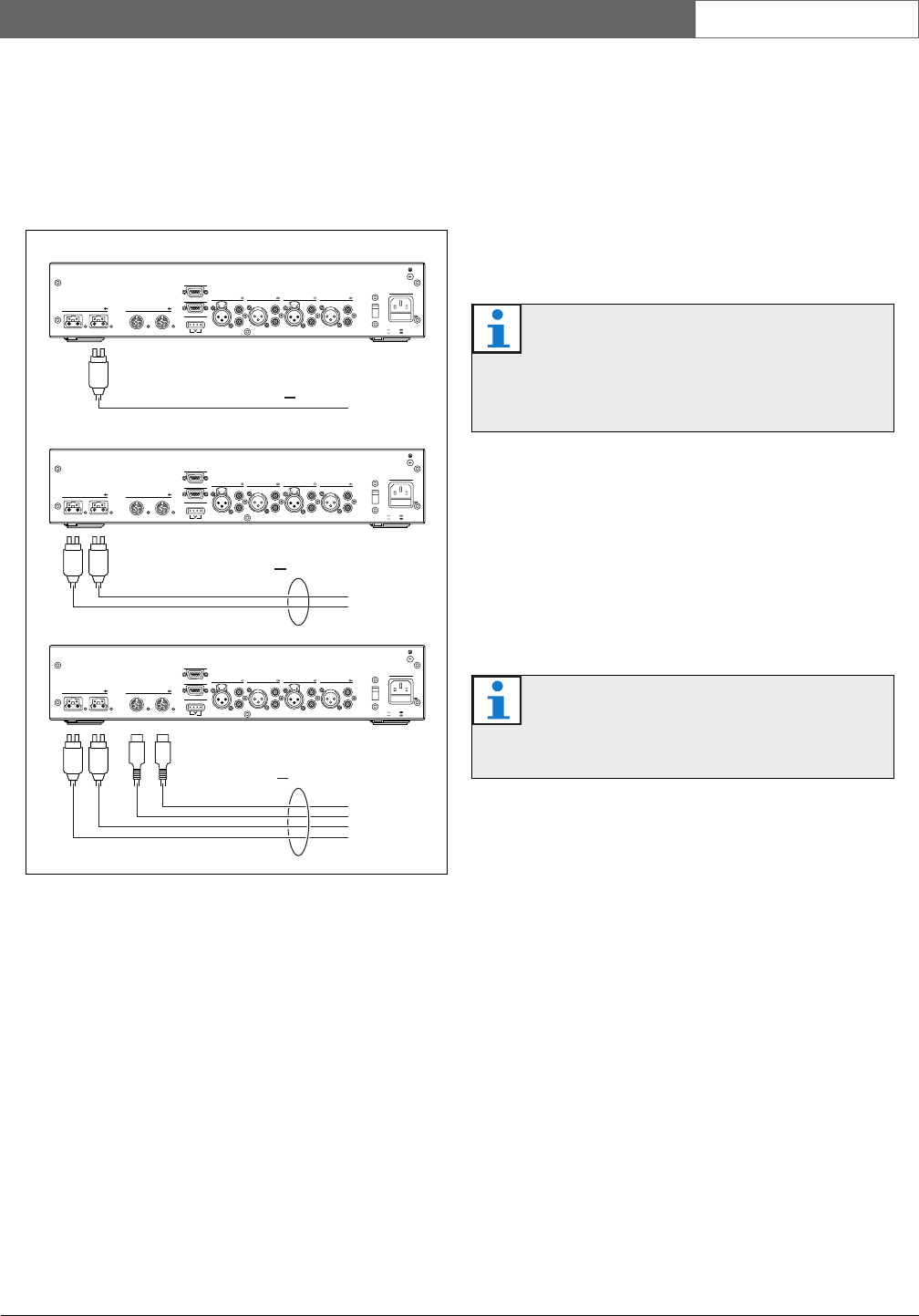
2.6.3 Power supplies
2.6.3.1 Introduction
The devices that supply power to the DCN are the
central control unit and the extension power supply
(refer to figure 2.1 and figure 2.2). The power that the
central control unit supplies includes the power that the
optical network uses.
2.6.3.2 DCN-WCCU
2.6.3.3 DCN-EPS
figure 2.1: DCN power supply: DCN-WCCU
Note
If the power is higher than shown in figure 2.1,
an overload situation occurs (refer to section
2.6.4).
OK Fault
Fault
RS 232
Network
12
Audio In 1 Audio Out 1 Audio In 2 Audio Out 2
Mains
Port 2
115:100-120V 50-60Hz T2.5A 250V
230:220-240V 50-60Hz T2A H 250V
RS 232 Port 1
Trunk
12
230
P<65W
DCN-WCCU
DCN-WCCU
DCN-WCCU
P<130W
P<130W
OK Fault
Fault
RS 232
Network
12
Audio In 1 Audio Out 1 Audio In 2 Audio Out 2
Mains
Port 2
115:100-120V 50-60Hz T2.5A 250V
230:220-240V 50-60Hz T2A H 250V
RS 232 Port 1
Trunk
12
230
OK Fault
Fault
RS 232
Network
12
Audio In 1 Audio Out 1 Audio In 2 Audio Out 2
Mains
Port 2
115:100-120V 50-60Hz T2.5A 250V
230:220-240V 50-60Hz T2A H 250V
RS 232 Port 1
Trunk
12
230
figure 2.2: DCN power supply: DCN-EPS
Note
If the power is higher than shown in figure 2.2,
an overload situation occurs (refer to section
2.6.4).
OutOutOutIn
Tap-offTrunk
OutOutOutIn
Tap-offTrunk
DCN-EPS
DCN-EPS
e
P<85W
P < 255 W

Bosch Security Systems | 2007-02 | 9922 141 70691 en
DCN Wireless | Installation and User Instructions | System Design and Planning en | 17
2.6.4 Overload indication
Each DCN socket of the central control unit and
extension power supply has a red LED that comes on to
show that there is a power overload. An overload occurs
when:
• The necessary power for the devices is greater than
that is supplied.
• A short-circuit occurs.
When an overload occurs, the sockets are deactivated
and the connected devices do not operate. The socket
checks every 8 seconds (DCN-WCCU) or 30 seconds
(DCN-EPS) for power overloads.
2.6.5 Extension cables
Extension cables (LBB4116) have a direct effect on the
available power. The longer an extension cable, the less
power is available to drive the connected devices. You
must chose the length of the extension cables carefully
(refer to section 2.7.5).
2.7 Cable lengths
2.7.1 Maximum length
The cable length between the central control unit and
the furthest device from the central control unit must
not be more than 250 m. The cable length includes the
device cable and extension cables.
2.7.2 To first regenerative tap-off
The total cable length between the central control unit
and the first regenerative tap-off socket must not be
more than 100 m. This includes the device cables and
extension cables.
2.7.3 Between regenerative tap-offs
The total cable length between two regenerative tap-off
sockets must not be more than 100 m. This includes the
device cables and extension cables.
2.7.4 Open-ended DCN cables
‘Open-ended’ DCN cables are DCN cables of which the
socket is not connected to a device in the DCN.
‘Open-ended’ cables can cause an incorrect operation of
the system. You can ‘close’ the extension cable with a
termination plug (refer to the DCN Next Generation
Installation and User Instructions). When the
‘open-ended’ cable is connected to a termination plug,
the system operates correctly.
2.7.5 Power correction
2.7.5.1 Introduction
The necessary power from a DCN socket of the central
control unit and the extension power supply is affected
by:
• The type and number of connected devices.
• The lengths of the connected extension cables.
The power correction graph (refer to figure 2.3) corrects
the power level to compensate for the extension cables.
2.7.5.2 Calculation
To find the correction for each DCN socket of the
central control unit and the extension power supply
with the graph, you must first calculate:
• The total power consumption of the devices that are
connected to the socket. Refer to section 2.7.5.3.
• The length of the longest extension cable sequence.
Refer to section 2.7.5.4.
Bosch Security Systems | 2007-02 | 9922 141 70691 en
DCN Wireless | Installation and User Instructions | System Design and Planning en | 18
2.7.5.3 Total power consumption
Do as follows:
1 Find the power consumption of each device from the
consumption table (refer to table 2.2).
2 Add together the power used by all the devices. The
result is the total power consumption of the devices
that are connected to the socket.
2.7.5.4 Length of the longest extension cable
sequence
Do as follows:
1 Add together the lengths of all extension cables in
the longest sequence.
For example, an extension cable of 20 m is connected
directly to a DCN socket of the central control unit. To
the extension cable, a trunk splitter is connected. To
each tap-off socket of the trunk splitter, an extension
cable is connected. One extension cable has a length of
10 m, the other extension cable has a length of 40 m.
The length of the longest extension cable sequence is, in
this example: 20 + 40 = 60 m.
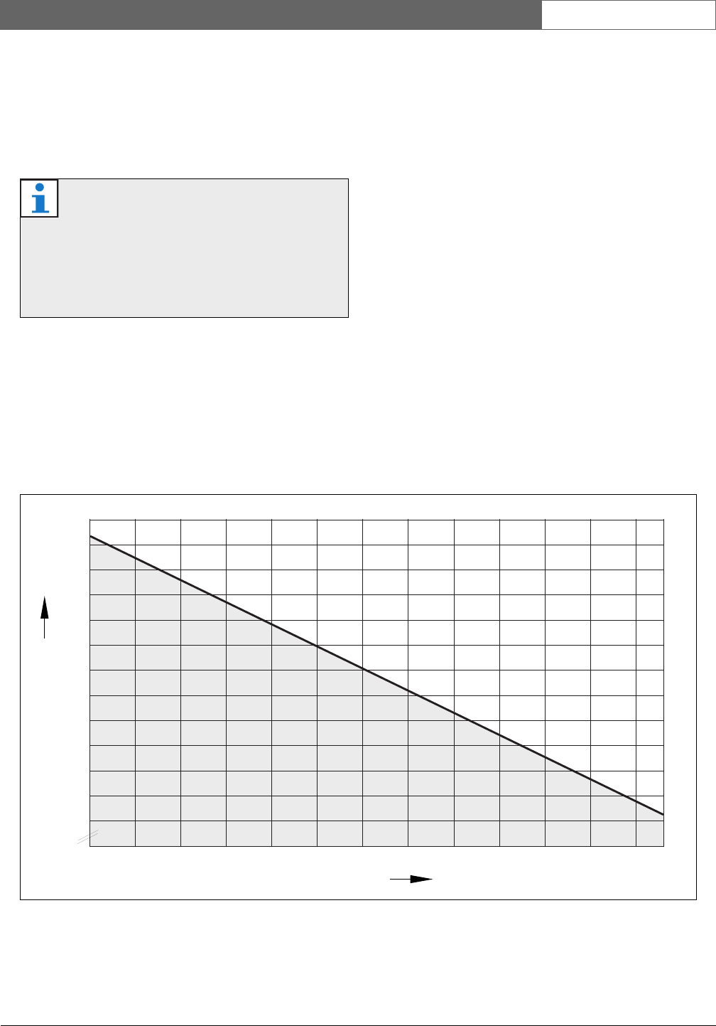
2.7.5.5 Graph
The power correction graph (refer to figure 2.3) corrects
the power level to compensate for the extension cables.
Do as follows:
1 Find the total power consumption (refer to section
2.7.5.3) on the vertical axis (Y) of the power
correction graph. For example, 40 W.
2 Find the length of the longest extension cable
sequence (refer to section 2.7.5.4) on the horizontal
axis (X) of the power correction graph. For example,
60 m.
3 The intersection of both values gives the necessary
power from the socket. For example, 53 W.
figure 2.3: Power correction graph
60
55
50
45
75
70
80
85
65
40
Y: Power (Watt)
35
30
25
20
15
10
20 40 60 80 100 120 140 160 180
X: Extension cable (m)
DCN-WCCU
+ DCN-EPS
200 220 240 250
5
0
6
11
16
21
27
32
38
43
49
54
60
65
70
76
81
6
12
18
24
30
36
42
48
54
60
66
72
78
84
6
13
20
26
33
40
46
53
60
66
73
80
7
15
22
30
37
45
52
60
67
75
82
8
17
25
34
42
51
60
68
77
85
9
18
27
36
46
55
64
73
83
10
20
30
40
50
60
70
80
11
21
32
43
54
65
76
12
24
36
48
60
72
84
13
26
40
53
66
80
15
30
45
60
75
17
34
51
68
85
18
36
55
73
Bosch Security Systems | 2007-02 | 9922 141 70691 en
DCN Wireless | Installation and User Instructions | System Design and Planning en | 19
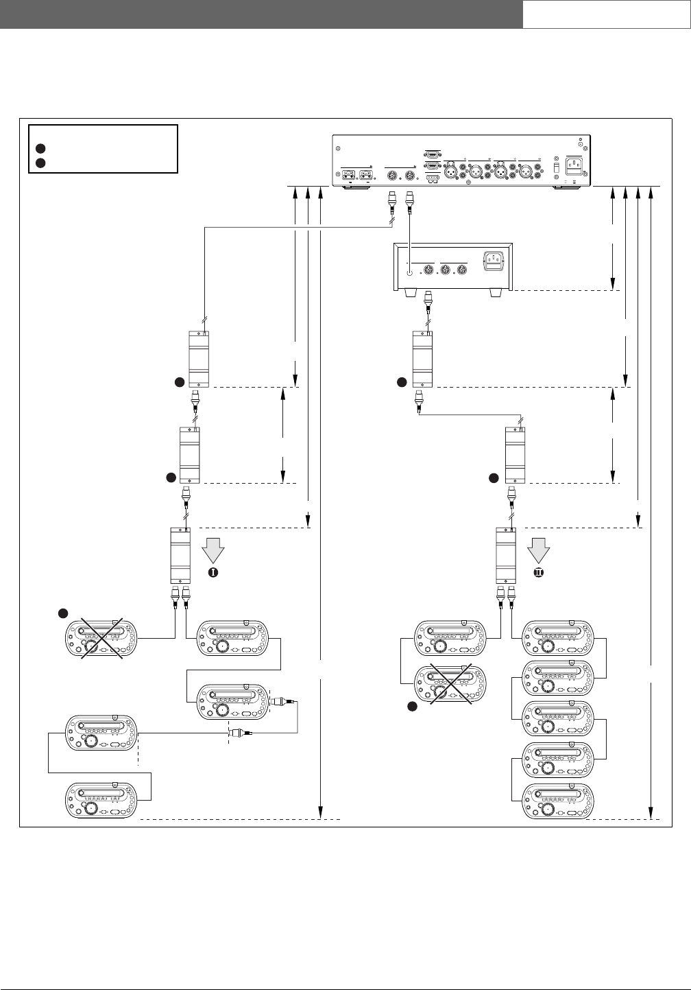
2.8 Examples
2.8.1 Cable lengths
Point I
The maximum available power with 240 m of extension
cables is 19 W (refer to figure 2.3). Because the first and
second trunk splitter use 2.6 W, the available power at
point I is 19 - 2.6 = 16.4 W.
Point II
The maximum available power with 240 m of extension
cable is 25 W (refer to figure 2.3). Because the first and
second trunk splitter use 2.6 W, the available power at
point II is 25 - 2.6 = 22.4 W.
figure 2.4: Example with cable lengths
OutOutOutIn
Tap-offTrunk
NC C C NO
Fault
RS 232
Network
12
AudioIn 1 AudioOut 1 Audio In 2 AudioOut 2
Mains
Port 2
115:100-120V 50-60Hz T2.5A 250V
230:220-240V 50-60Hz T2A H 250V
RS 232 Port 1
Trunk
12
48V 48V
230
Trunk
LBB4114/00
DCN-WCCU
DCN-EPS
250 m (max)
250 m (max)
240 m
240 m
100 m
100 m
2m
LBB4114/00
LBB4114/00 100 m
100 m
5x2m=10m
5x2m=10m
LBB4114/00
2m
LBB4114/00 LBB4114/00
Regenerative tap-off
Legend
R
R R
R
R
P
P
Power overload
P
Bosch Security Systems | 2007-02 | 9922 141 70691 en
DCN Wireless | Installation and User Instructions | System Design and Planning en | 20
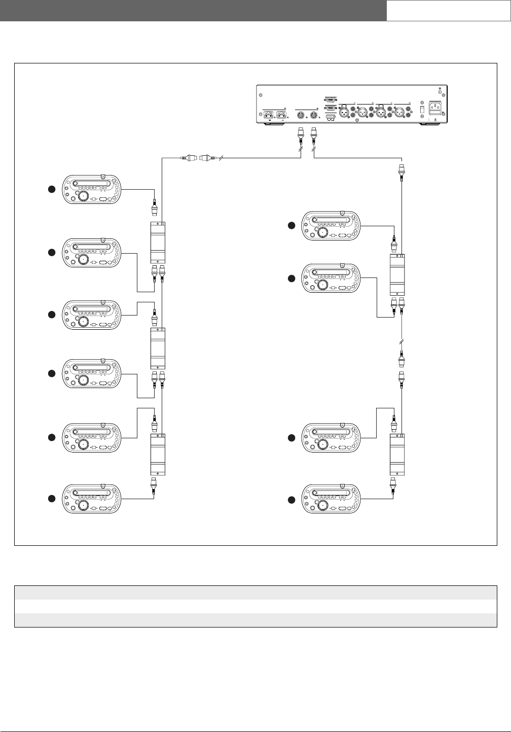
2.8.2 Power correction
figure 2.5: Example with interpreter desks (DCN-IDESK)
LBB4114/00
50 m 20 m
LBB4114/00LBB4114/00
LBB4114/00
LBB4114/00
3
3
4
4
4
2
2
2
2
2
NCCCNO
Fault
RS 232
Network 12
AudioIn 1 AudioOut 1 AudioIn 2 AudioOut 2
Mains
Port 2
115:100-120V 50-60Hz T2.5A 250V
230:220-240V 50-60Hz T2A H 250V
RS 232 Port 1
Trunk 12
48V 48V
230
DCN-WCCU
10 m
table 2.3: Example with interpreter desks (DCN-IDESK)
Socket Power for devices Cable length Corrected power
Trunk 1 50.7 W 50 m 64.0 W
Trunk 2 56.6 W 30 m 64.7 W
Bosch Security Systems | 2007-02 | 9922 141 70691 en
DCN Wireless | Installation and User Instructions | System Design and Planning en | 21
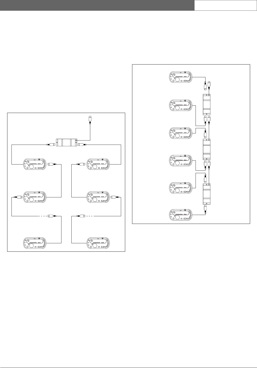
2.9 Interpretation devices
The maximum number of interpreter desks you can
install in an interpreter booth is six. Refer to figure 2.6
and figure 2.7 for two examples that use LBB4114/00
Trunk Splitters and LBB4115/00 Protected Trunk
Splitters.
With an LBB4114/00 Trunk Splitter, you can connect
the interpreter desks in series (refer to figure 2.6). If an
interpreter desk becomes defective, the defective desk
can have an effect on all other interpreter desks that
have a connection to the same trunk.
With an LBB4115/00 Protected Trunk Splitter, you can
connect two interpreter desks (refer to figure 2.7). If an
interpreter desk becomes defective, the defective desk
has no effect on all other interpreter desks that have a
connection to the same trunk.
figure 2.6: Interpreter booths with LBB4114/00
LBB4114/00
figure 2.7: Interpreter booths with LBB4115/00
LBB4115/00
LBB4115/00
LBB4115/00
Bosch Security Systems | 2007-02 | 9922 141 70691 en
DCN Wireless | Installation and User Instructions | System Design and Planning en | 22
3 Optical network design
3.1 Introduction
The DCN Wireless has three parts: the wireless
network, the DCN and the optical network. This
chapter tells how to design the optical network.
3.2 Calculation tool
The calculation tool makes the planning and design of
the optical network easier. You can find the calculation
tool on the CD-ROM that is supplied with your system.
3.3 Limits
Make sure that these limits are not exceeded when you
make the optical network:
Limit 1: Control capacity
The maximum number of nodes in the optical network
is 63 (refer to section 3.4).
Limit 2: Number of devices
The maximum number of devices that you can connect
to the optical network of the central control unit is 16.
The maximum number of DCN-WAP Wireless Access
Points in the optical network is 1.
Limit 3: Power capacity
The maximum power that the optical network sockets
of the central control unit can supply is 65 W (refer to
section 3.5).
Limit 4: Cables
Refer to section 3.6:
• The maximum length of a POF cable is 50 m.
• The maximum cable length (POF and GOF) of the
optical network is dependent on the number of
nodes in the optical network.
• The minimum bend radius of a 90 degree bend in a
POF cable is 110 mm.
• The minimum coiling radius of a POF cable is
110 mm.
3.4 Control capacity
Each device in the optical network has a number of
nodes (refer to table 3.1). The maximum number of
nodes in the optical network is 63.
3.5 Power capacity
3.5.1 Introduction
Each device uses power and most devices do not have
an independent power supply.
3.5.2 Power consumption
The table shows the power each device in the optical
network uses.
table 3.1: Nodes
Device Nodes
DCN-CCU 2
DCN-WAP 1
LBB4402/00 1
LBB4404/00 1
LBB4410/00 1
LBB4414/10 0
INT-TX04 1
INT-TX08 2
INT-TX16 4
INT-TX32 8
PRS-4DEX4 1
table 3.2: Power consumption
Device Watt
DCN-WAP 4
LBB4402/00 7. 6
LBB4404/00 10.5
LBB4410/00 3.9
LBB4414/10 4.6
PRS-4DEX4 6.0
Note
The Integrus transmitters do not use power from
the system.
Bosch Security Systems | 2007-02 | 9922 141 70691 en
DCN Wireless | Installation and User Instructions | System Design and Planning en | 23
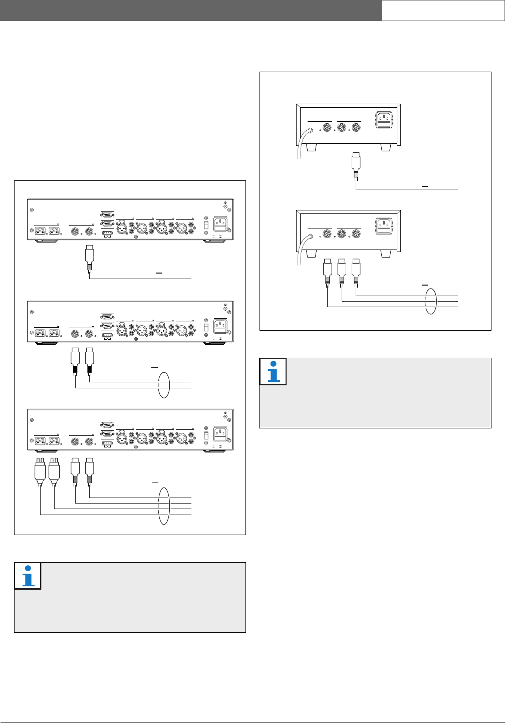
3.5.3 Power supply
The device that supplies power to the optical network is
the central control unit, refer to figure 3.1. The power
that the central control unit supplies includes the power
that the DCN uses.
If more power is necessary, you must install external
power supplies in the optical network. The devices
below can connect to external power supplies:
• LBB4410/00 Network Splitter (refer to the DCN
Next Generation Installation and User Instructions).
• LBB4414/10 Fiber Interface (refer to the DCN Next
Generation Installation and User Instruction).
3.5.4 Overload indication
Each optical network socket of the central control unit
has a red LED that comes on to show that there is a
power overload. An overload occurs when the
necessary power for the devices is greater than that
supplied. The sockets are deactivated and the devices
connected to the central control unit do not operate.
The socket checks every 8 seconds for power overloads.
3.6 Cabling
3.6.1 Introduction
Many devices in the optical network have two optical
network sockets that are interchangeable. You can use
the two optical network sockets to make a redundant
ring.
3.6.2 Definitions
The optical network uses two types of cable:
•POF
Plastic Optical Fiber.
•GOF
Glass Optical Fiber.
figure 3.1: Optical network power supply
OK Fault
Fault
RS 232
Network
12
Audio In 1 Audio Out 1 Audio In 2 Audio Out 2
Mains
Port 2
115:100-120V 50-60Hz T2.5A 250V
230:220-240V 50-60Hz T2A H 250V
RS 232 Port 1
Trunk
12
230
P<65W
DCN-WCCU
DCN-WCCU
DCN-WCCU
P<65W
P<130W
OK Fault
Fault
RS 232
Network
12
Audio In 1 Audio Out 1 Audio In 2 Audio Out 2
Mains
Port 2
115:100-120V 50-60Hz T2.5A 250V
230:220-240V 50-60Hz T2A H 250V
RS 232 Port 1
Trunk
12
230
OK Fault
Fault
RS 232
Network
12
Audio In 1 Audio Out 1 Audio In 2 Audio Out 2
Mains
Port 2
115:100-120V 50-60Hz T2.5A 250V
230:220-240V 50-60Hz T2A H 250V
RS 232 Port 1
Trunk
12
230
Note
If only one of the optical network sockets has a
power overload, the two overload LEDs come
on.
Note
The two optical network connectors are the
same.
Bosch Security Systems | 2007-02 | 9922 141 70691 en
DCN Wireless | Installation and User Instructions | System Design and Planning en | 24
3.6.3 Optical fiber length
Because of optical attenuation, the maximum length of
optical network cables (LBB4416) is 50 m. You can use
GOF and fiber interfaces to increase the distance
between devices to a maximum of 1500 m.
3.6.4 Cable couplers
You can use the LBB4419/00 Cable Couplers to
connect optical network cables to each other. A cable
coupler causes optical attenuation. Each cable coupler
decreases the maximum distance between two devices
in the optical network (normally 50 meters) with
20 meters.
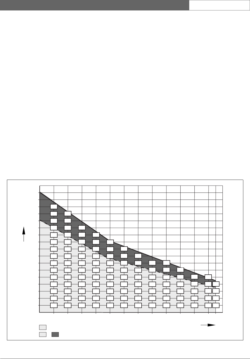
3.6.5 Maximum cable length
The maximum cable length (LBB4416 and GOF) of the
optical network is dependent on:
• The number of nodes
• The number of LBB4414/10 Fiber Interfaces
Do as follows:
1 Find the number of nodes of each device from the
node value table (refer to table 3.1). Add together the
nodes of all devices.
2 With the value of step 1, use the graph (refer to
figure 3.2) to find the maximum cable length without
LBB4414/10 Fiber Interfaces.
3 Count the number of LBB4414/10 Fiber Interfaces.
Each fiber interface decreases the maximum cable
length from step 2 with 18 m.
Note
If the distance between two devices is less than
100 m, use a network splitter between devices
to remove the use of fiber interfaces. Use only
the trunk sockets of the network splitter in this
case.
figure 3.2: Cable correction graph
950
5010152025
Nodes
30 35 40 45 50 55 60 63
1050
1150
1250
1350
1450
1550
1650
1750
1850
1950
2050
2150
Max. cable length (m)

Bosch Security Systems | 2007-02 | 9922 141 70691 en
DCN Wireless | Installation and User Instructions | System Design and Planning en | 25
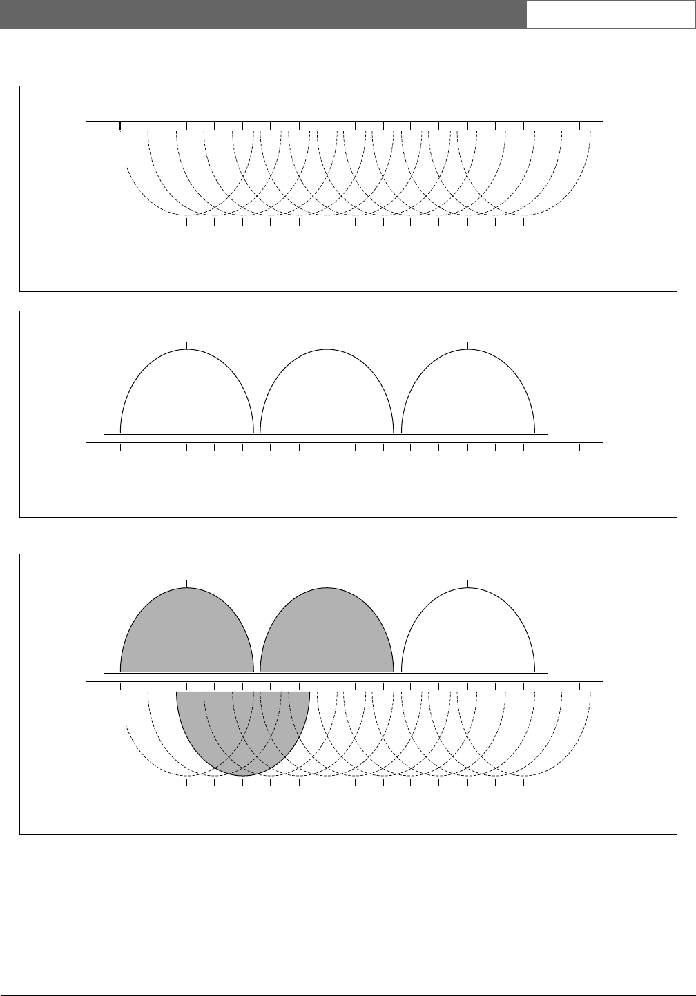
3.6.6 Bending
The minimum bend radius of a 90 degree bend in an
LBB4416 cable is 110 mm (refer to figure 3.3). A
180 degree bend is the same as two 90 degree bends.
3.6.7 Coiling
The minimum coiling radius of an LBB4416 cable is
110 mm (refer to figure 3.4).
3.7 Example layouts
3.7.1 Introduction
The number and type of devices that make the optical
network give the layout of the optical network. This
chapter shows examples of the possible layouts of
optical networks.
figure 3.3: Bend radius
figure 3.4: Coiling radius
R=110 mm
R=110 mm
Bosch Security Systems | 2007-02 | 9922 141 70691 en
DCN Wireless | Installation and User Instructions | System Design and Planning en | 26
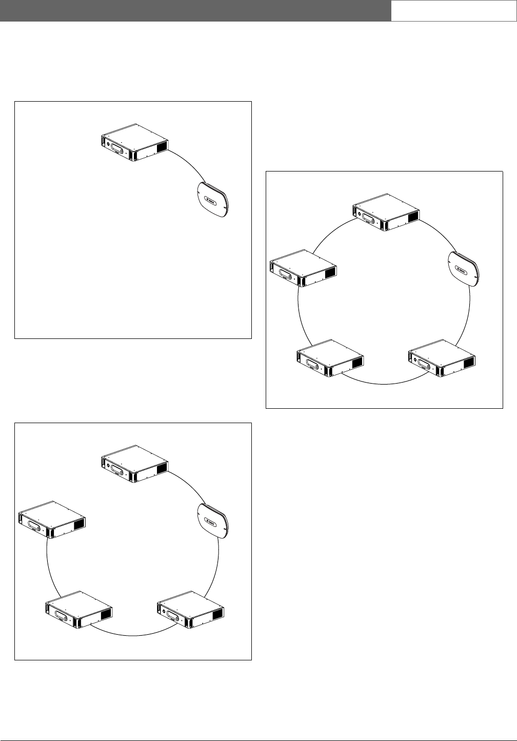
3.7.2 Basic optical network
Refer to figure 3.5 for an example of a basic optical
network.
3.7.3 Extended optical network
Refer to figure 3.6 for an example of an extended
optical network.
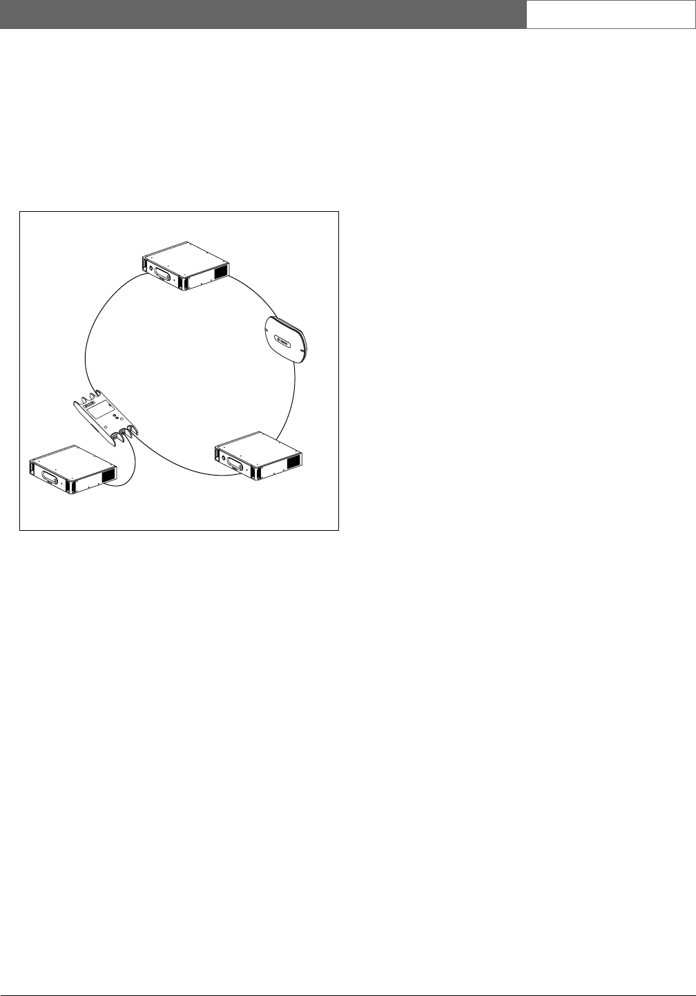
3.7.4 Redundant cables
The example of the extended optical network (refer to
figure 3.6) has no redundant cable. If the cable between
the central control unit (DCN-WCCU) and the wireless
access point (DCN-WAP) breaks, the central control
unit cannot transmit data to the wireless access point. A
solution for this problem is to use redundant cable (refer
to figure 3.7 for an example).
The example of the system without redundant cable
(refer to figure 3.6) has no connection between the
cobranet interface (LBB4404/00) and the central control
unit (DCN-WCCU). The example of the system with
redundant cable has a connection between the Cobranet
Interface and the central control unit. This connection
makes a ring. If a cable breaks, the optical network
continues to operate.
The maximum total power of all devices in the
redundant optical network is 65 W. If the optical
network is defective near the central control unit, the
other socket can supply power to all of the optical
network.
figure 3.5: Basic optical network
figure 3.6: Extended optical network
DCN-WCCU
DCN-WAP
DCN-WCCU
DCN-WAP
LBB4404/00
INT-TX
PRS-4DEX4
figure 3.7: Redundant optical network
DCN-WCCU
DCN-WAP
LBB4404/00
INT-TX
PRS-4DEX4
Bosch Security Systems | 2007-02 | 9922 141 70691 en
DCN Wireless | Installation and User Instructions | System Design and Planning en | 27
3.7.5 Tap-offs
The network splitter (LBB4410/00) lets you make
tap-offs (refer to figure 3.8 for an example). Tap-offs
cannot be redundant. If the cable between the network
splitter and the digital audio expander (PRS-4DEX4)
becomes defective, the digital audio expander has no
connection to the central control unit.
figure 3.8: Redundant optical network with tap-off
DCN-WCCU
DCN-WAP
PRS-4DEX4 INT-TX
LBB4410/00
Bosch Security Systems | 2007-02 | 9922 141 70691 en
DCN Wireless | Installation and User Instructions | System Design and Planning en | 28
4 Camera control
4.1 Introduction
The central control unit can automatically point video
cameras in the direction of the delegate or chairman
who speaks. You can connect video cameras to the
central control unit through a video switcher or directly
to the central control unit. Use a video switcher to
connect more that one video camera and video display
to the central control unit.
4.2 Scenarios
These scenarios are possible:
• Direct camera control in a system without a DCN
control PC. Refer to the DCN Next Generation
Installation and User Instructions.
• Camera control through a video switcher in a system
without a DCN control PC. Refer to the DCN Next
Generation Installation and User Instructions.
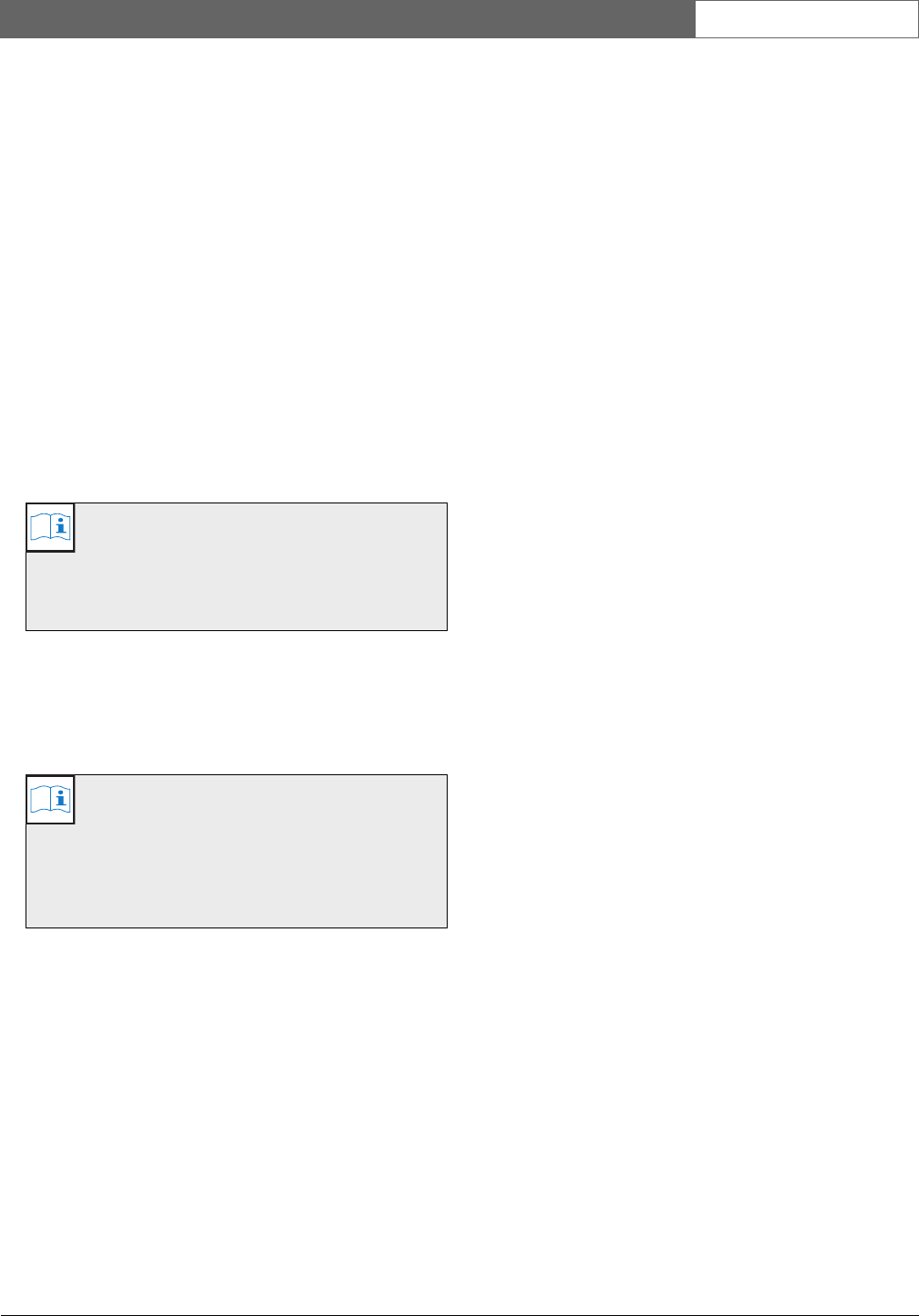
5 Infra-red wireless
language distribution
You can connect the system to an Integrus digital
infra-red language distribution system. This system has a
transmitter, radiators and receivers.
Note
Refer to the Integrus Installation and User
Instructions for more data.
figure 5.1: Integrus
Bosch Security Systems | 2007-02 | 9922 141 70691 en
DCN Wireless | Installation and User Instructions | System Design and Planning en | 29
6 CobraNet
CobraNet is a standard for the transport of real-time
digital audio and control data through an Ethernet
network. A CobraNet network can transport a
maximum of 64 channels of 48 kHz, 20-bit audio
through a 100 Mbit link connection in each direction.
Many manufacturers of professional audio devices
support the CobraNet standard.
The DCN Wireless digital congress network can
connect to CobraNet networks with the LBB4404/00
Cobranet Interface. For example, you can use the
LBB4404/00 Cobranet Interface to:
• Benefit from Ethernet infrastructure
• Transport audio signals over large distances
PC data, for example data from the DCN Wireless
Open Interface can co-exist with CobraNet data on the
same Ethernet network when you use managed
Ethernet switches that are approved by Peak Audio.
7User set-up
7.1 Public areas and walkways
Keep public areas clear of system and extension cables
and connections.
7.2 Headphones/headsets
Put headphones or headsets with:
• Wireless discussion units.
• Interpreter desks.
• Channel selector.
• Integrus receivers.
Acoustic feedback between the connected headphones
or headsets and the microphone occurs when:
• The volume level is set too high.
• The headphones are too close to activated
microphones.
7.3 Speaking distance
The recommended speaking distance from the
microphone is 0.2 m to 0.4 m.
7.4 Interpreter booths
Make sure each interpreter booth has sufficient
dimensions. The International Organization for
Standardization (ISO) gives the specification for
interpreter booths. Refer to standard ISO 2603 ‘Booths
for simultaneous interpretation - General characteristics
and equipment’ for more data.
Note
Refer to the DCN Next Generation Installation
and User Instructions for the LBB4404/00
Cobranet Interface.
Note
Refer to the website of Peak Audio
(www.peakaudio.com) for:
• More data about CobraNet networks.
• A list of approved Ethernet switches.