Busch Jaeger Elektro FHIWD1US ABB-free at home in wall devices User Manual Manual ABB Dimmer Switch 2 wire
Busch-Jaeger Elektro GmbH ABB-free at home in wall devices Manual ABB Dimmer Switch 2 wire
Contents
- 1. Manual - ABB Ceiling Fan Controller
- 2. Manual - ABB Dimmer Switch (2-wire)
- 3. Manual - ABB Dimmer Switch (3-wire)
- 4. Manual - ABB Keypad
- 5. Manual - ABB Light Switch
Manual - ABB Dimmer Switch (2-wire)
QR-Link
English
EN
FR
ES
...
DS-3.1
DS-3.1/ Date
IMPORTANT: Carefully read all instructions and safety
information about this device before operation. Please leave
this document with the homeowner for future reference.
WARNING: Installation must be performed by a licensed
electrician or electrical professional. Improper installation can
cause property damage, personal injury, or loss of life.
WARNING: FIRE
Work performed incorrectly can cause res. Use the device
only in a certied wall box. Recommended: Carlon® products,
which have a high safety standard. Do not connect equipment that
is not intended to be controlled by this device. Please refer to the
equipment manufacturer if it is unclear.
WARNING: DAMAGED DEVICE
A damaged device could result in serious injury or death. If
the device shows any damage to its body or wiring insulation,
immediately turn off the power at the circuit breaker or fuse. Replace
the device with an undamaged device. Do not try to repair the device.
IMPORTANT: Only use with xed lighting loads.
Intended Use
The ABB Dimmer Switch controls dimmable lights. It has a wireless
control unit that connects it to the ABB-free@home system. For
information about the many functions of this device, see the system
manual at www.abb.com/us/freeathome.
INSTALLATION
WARNING: SHOCK HAZARD
1. Turn the power OFF at the circuit breaker before installing.
2. Remove the old wall plate from the wall. Remove the old switch/
dimmer from the wall box.
3. Disconnect all three wires from the switch/dimmer.
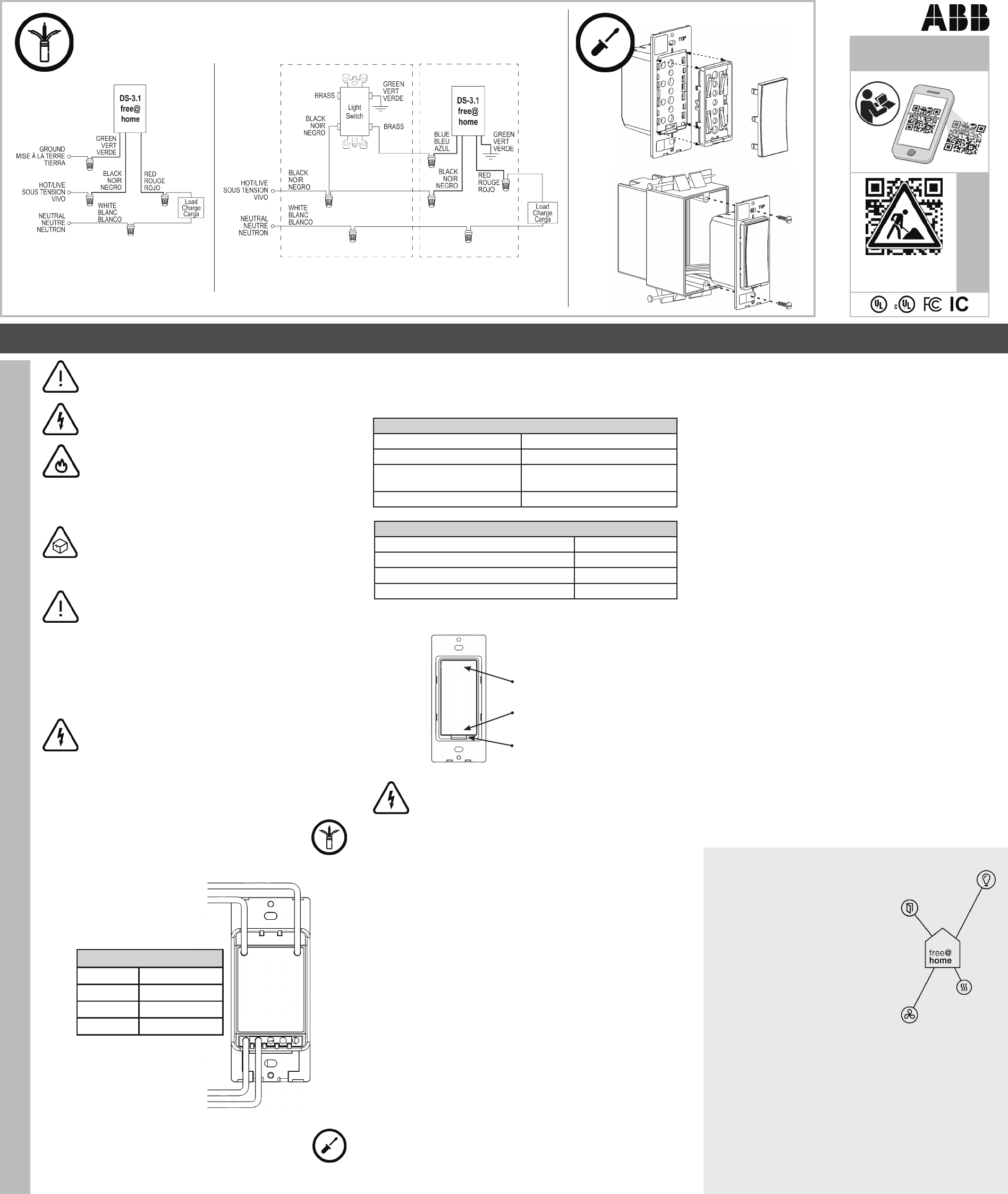
4. Connect the Dimmer Switch. (Refer to the wiring diagrams.)
A) Single-Location Installation
B) 3-Way Installation
Wiring Connection Diagrams
green
blue
black
red
Wiring Connection
Black Hot/Live (120VAC)
Blue Binary Input
Red Load Output
Green Ground
5. Mount the Dimmer Switch. Using a screwdriver and the
screws provided, mount the ABB Dimmer Switch.
6. Replace the wall plate.
7. Turn the power ON at the circuit breaker.
Replacing the Rocker and Bezel: The rocker and bezel of the device
can be exchanged. Turn the power OFF before removing the adapter
bezel with a screwdriver. Turn the power ON after the rocker and bezel
have been assembled.
DS-3.1 Technical Data
Operating Voltage 120 VAC, 60 Hz
Connection No Neutral Wire Required
Wireless Transmission Protocol free@home, 2.400 - 2.483 GHz,
Meshed
Ambient Operating Temperature 23° F to 113° F (-5°C to 45°C)
Load Table
Incandescent or Halogen Lamp 300 W
Electronic Low Voltage Transformer (ELV) 200 W
CFL Lamps 150 W
LED Lamps (Max. 20 Lamps Allowed) 150 W
OPERATION
Short press: Switch ON
Long press: Brighter
Short press: Switch OFF
Long Press: Dim Down
Safety-Off Switch*
WARNING: *SAFETY-OFF SWITCH
May result in serious injury or death. This switch allows the
user to turn off the power to safely replace a lamp. However,
the rocker on the device may have been congured to
operate a lamp other than the one switched off by the Safety Off. Before
replacing a lamp, verify that the wires to the lamp do not have power.
Turn the lamp on, then operate the Safety Off. If the lamp turns off when
the Safety Off is activated, it is safe to replace the lamp.
SETUP AND COMMUNICATION
After installation, the Dimmer Switch will immediately allow the lamp
to function. To control the switch wirelessly, it will need to be added to
the free@home network. Detailed information about setup is available
in the technical reference manual and the online help for the System
Access Point at www.abb.com/us/freeathome.
1. To complete setup, you will need the ABB-free@home System
Access Point (SysAP) and a computer (tablet, laptop, or desktop
computer).
2. Walls, ceilings, and electrical equipment can affect wireless
communication, especially steel reinforcements or other large metal
objects. Electrical devices that send high-frequency signals (such
as computers, wireless routers, audio systems, and video systems)
should be at least 3-feet from this device.
3. When rst powered, the device is in discovery mode for 30 minutes.
This time period allows the SysAP to see and connect to the device.
During this time, the user can login to the SysAP and add the device
to the free@home network.
4. After 30 minutes, the device will automatically exit discovery mode.
To re-enter discovery mode, the user must turn the power OFF and
back ON again. This will place the device in discovery mode for
another 30 minutes.
5. Once a device has been added to a network, it will no longer enter
discovery mode at power-up. To add the device to a new network,
the user must rst force the device to forget its existing network
by resetting it back to factory settings. This takes two people to do
safely. Follow these steps to reset:
A) Turn the power OFF at the circuit breaker.
B) Turn the power ON at the circuit breaker while pressing the
bottom half of the rocker for at least 15 seconds, until the LED
light stops ashing.
C) Return to steps 3-4 of SETUP AND COMMUNICATION to
connect the device to a new network.
Codes
Install according to national and local electrical codes.
Grounding
When there is no ground connector in the wall box, the National
Electrical Code (NEC®) allows a control to be installed as a
replacement ONLY IF 1) a non-metal, non-burning faceplate is attached
with non-metal screws, OR 2) the circuit is protected by a ground fault
circuit interrupter (GFCI). When installing a control, be sure to cap or
remove the green wire before screwing the control into the wall box.
Cleaning:
To clean, wipe with a clean damp cloth. DO NOT use any chemical
cleaning solutions.
FCC/IC Information
This device complies with part 15 of the FCC Rules and Industry Canada license-exempt
RSS standard(s). Operation is subject to the following two conditions: (1) this device
may not cause interference, and (2) this device must accept any interference, including
interference that may cause unwanted operation. Modications not expressly approved by
the manufacturer could void the user’s authority to operate this equipment.
Note: This equipment has been tested and found to comply with the limits for a Class B
digital device, pursuant to part 15 of the FCC Rules. These limits are designed to provide
reasonable protection against harmful interference in a residential installation. This
equipment generates, uses and can radiate radio frequency energy and, if not installed and
used according to the instructions, may cause harmful interference to radio communications.
However, there is no guarantee that interference will not occur in an installation. If this
equipment does cause harmful interference to radio or television reception, which can be
tested by turning the equipment off and on, the user is encouraged to try to correct the
interference by doing one or more of the following:
• Reposition or move the receiving antenna.
• Increase the distance between the equipment and the receiver.
• Connect the equipment to an outlet on a different circuit (not the circuit used by the
receiver).
• Consult the dealer or an experienced radio/TV technician for help.
Customer Service
800-816-7809
7:00 am - 5:30 pm, CST, Monday - Friday
elec_custserv@tnb.com
Technical Support
888-385-1221, Option 1
7:00 am - 5:00 pm, CST, Monday - Friday
lvps.support@us.abb.com
For information about the many functions
of this device, see the system manual at
www.abb.com/us/freeathome
ABB Inc.
Electrication Products
8155 T&B Boulevard
Memphis, TN 38125
www.abb.com/us/freeathome
ABB-free@home is a trademark of ABB Inc. NEC is a registered trademark
of the National Fire Protection Association, Quincy, Massachusetts.
© 2018 ABB Inc.
Dimmer Switch (2-wire), ABB-free@home Installation and Operation Instructions
A B