CalAmp Wireless Networks BDD4T881 Paragon PD User Manual Annex A technical manual preliminary
CALAMP WIRELESS NETWORKS INC. Paragon PD Annex A technical manual preliminary
Contents
- 1. Annex A technical manual preliminary
- 2. Appendix A Preliminary version 2 00 April HC
Annex A technical manual preliminary
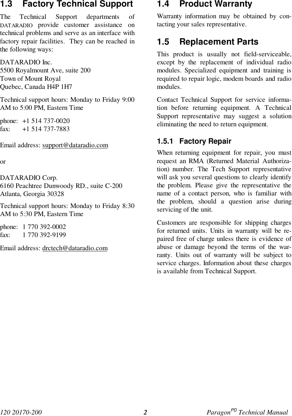
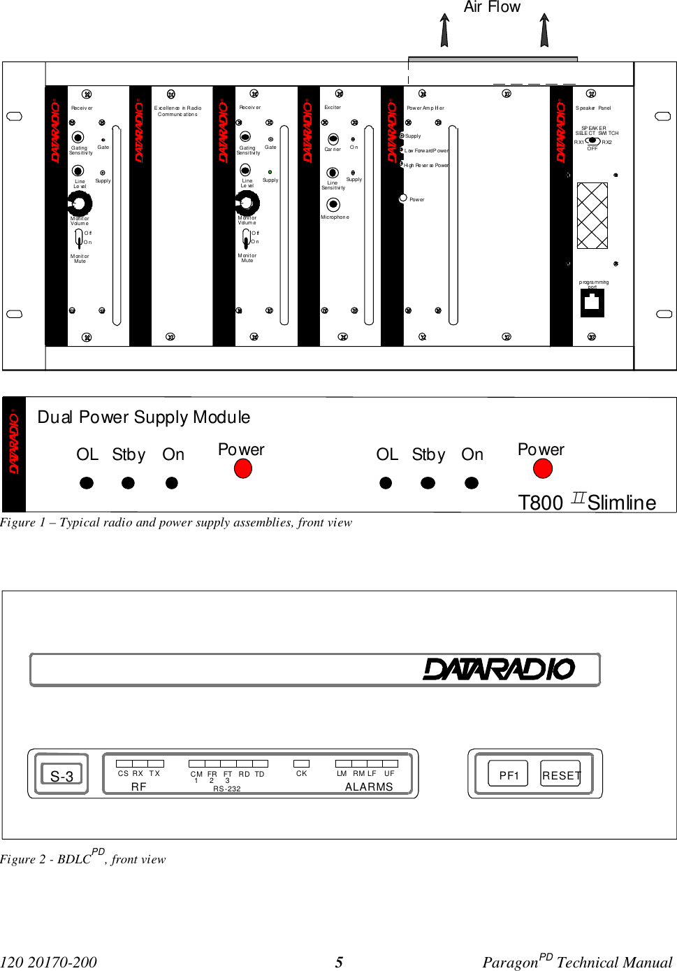
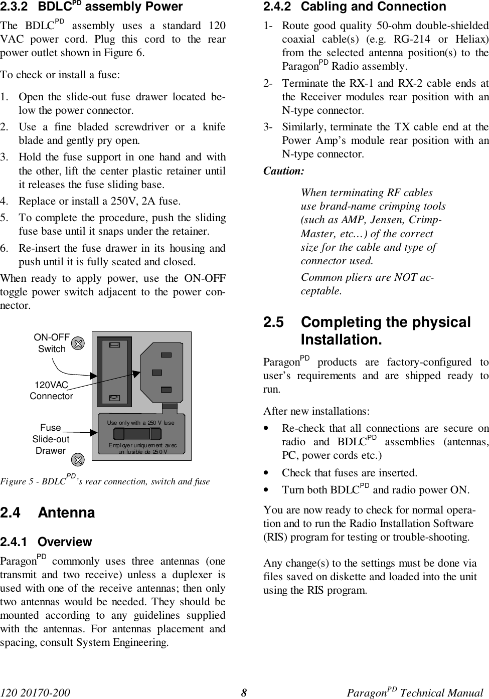
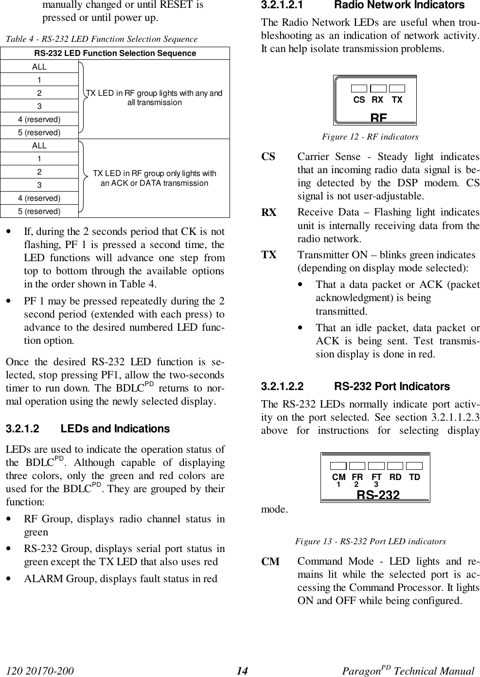
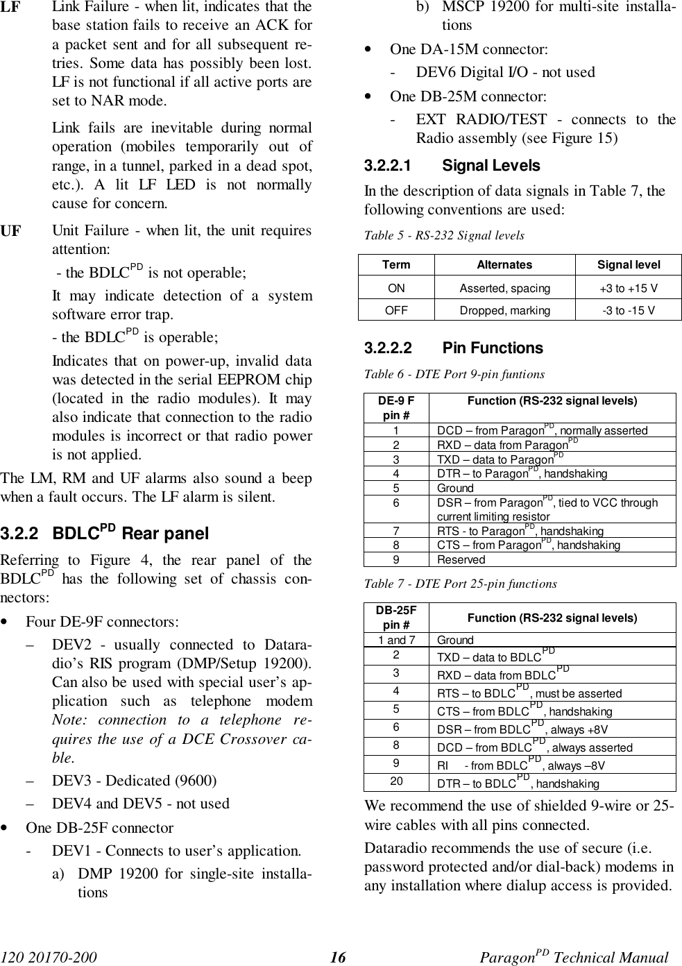
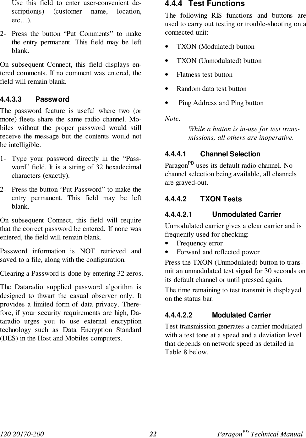
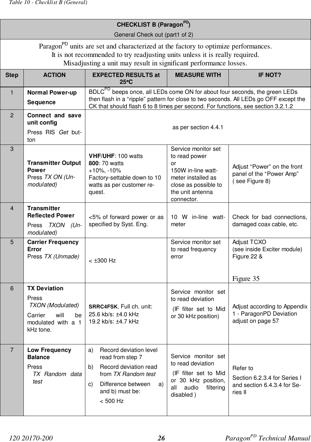
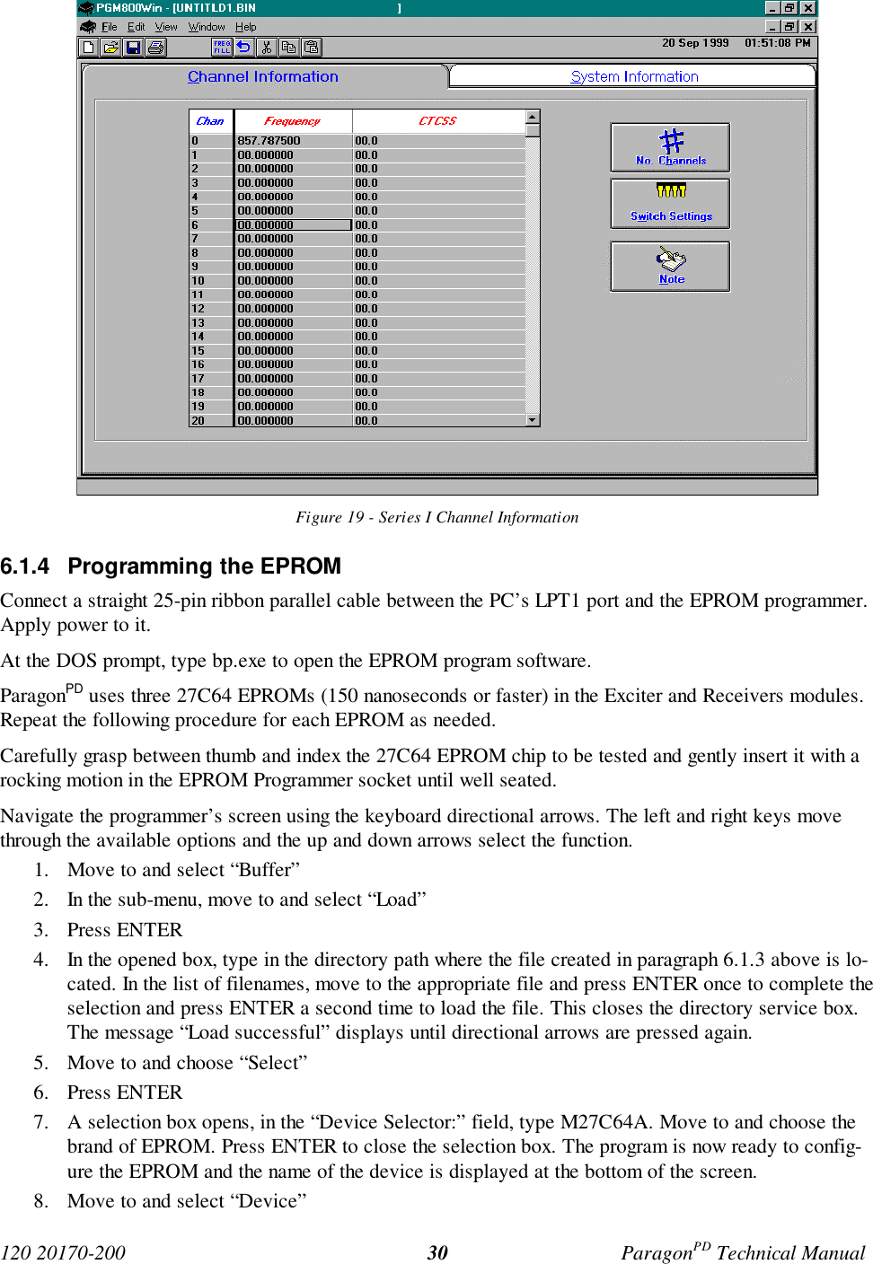
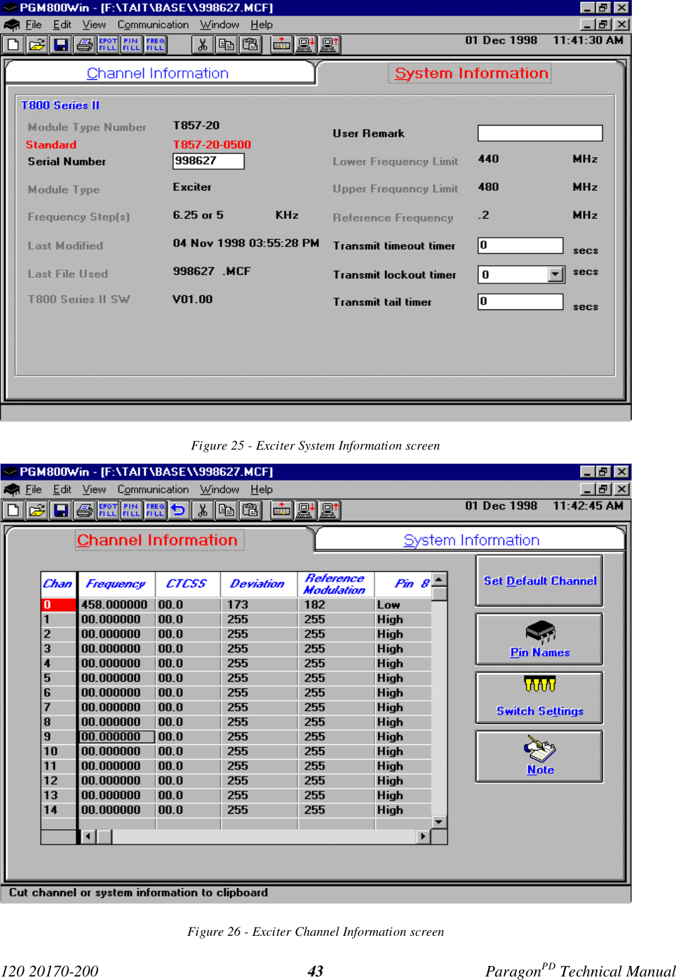
![120 20170-200 ParagonPD Technical Manual20Figure 17 - “Connect using” dialog window4.4.1.1 Connect ButtonThe Connect button is used to establish the re-quired communication link with the connectedParagonPD unit.1. Press the Connect button to open the “Con-nect using ” dialog window (see above).2. Select the appropriate COM port where theParagonPD’s RS-232 cable is connected onyour PC or portable computer and the portspeed (usually 19200) for the COM portselected. This speed is independent of thenetwork bit rate. Bit rates from 2400 to19200 are supported.3. Click OK. This validates the options enteredand starts the connection sequence.The program briefly displays pop-up windowmessages as it establishes a communications linkwith the equipment. Their content is not normallyuser-sensitive and only denotes proper operation.If an Error window opens, check the connectionsand that the right options were selected in the“Connect using” dialog window.Selecting an incorrect port speed in the “Connectusing” window will result in the status bar re-porting Connection failed!When communication linking is complete:• The Status bar reports Connection estab-lished.• All of the buttons grayed-out at startup be-come available.• The “Comment” and “Password” fields andtheir respective Put buttons are activated.• The product field indicates the productmodel connected to.• The Banner information is displayed.4.4.1.2 “Get” buttonAfter communication is established using theConnect button, press the Get button to down-load and automatically save the connectedBDLCPD configuration setting to a file namedwith the unit's on-air address (as set at the timeof manufacture). The RIS status bar will thenreport “All parameters are successfully re-trieved and saved in file [unit's on-air ad-dress].bp2. Any previous configuration in theprogram is overwritten.If you do not wish to overwrite an existing con-figuration or prefer to name the file yourself, usethe Get As button.Example: In a network using multiple BDLCPDhaving a common address, using the “Get As”button allows to uniquely name the files.4.4.1.3 “Get As” buttonAfter communication is established using theConnect button, press the Get As button to:• Open the “File, Save As” window with theASCII file *.bp2 (already selected).• Save the connected BDLCPD’s operatingcharacteristics (configuration setting) to afile, directory or drive of your choice.The program will ask before overwriting anexisting file.• Status bar reports “All parameters are suc-cessfully retrieved and saved in [filename].Connect usingCOM19600OK Cancel](https://usermanual.wiki/CalAmp-Wireless-Networks/BDD4T881.Annex-A-technical-manual-preliminary/User-Guide-127714-Page-27.png)
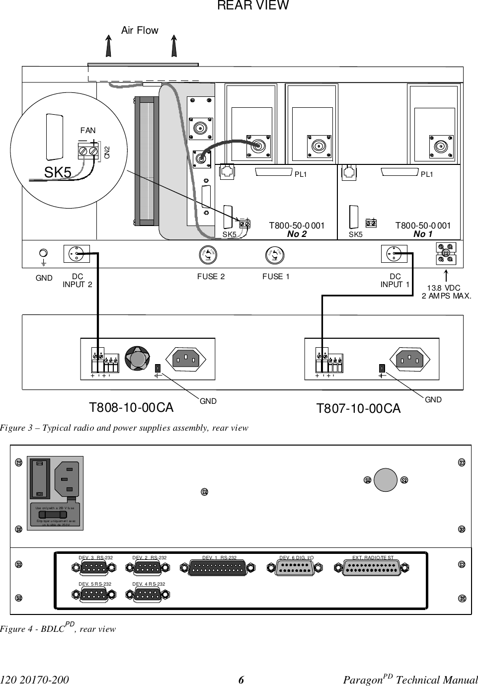
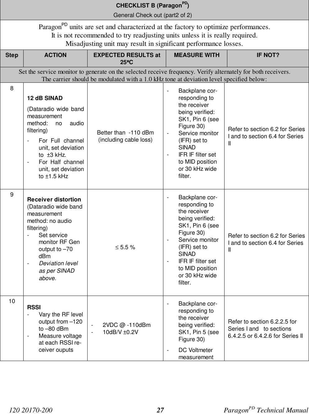
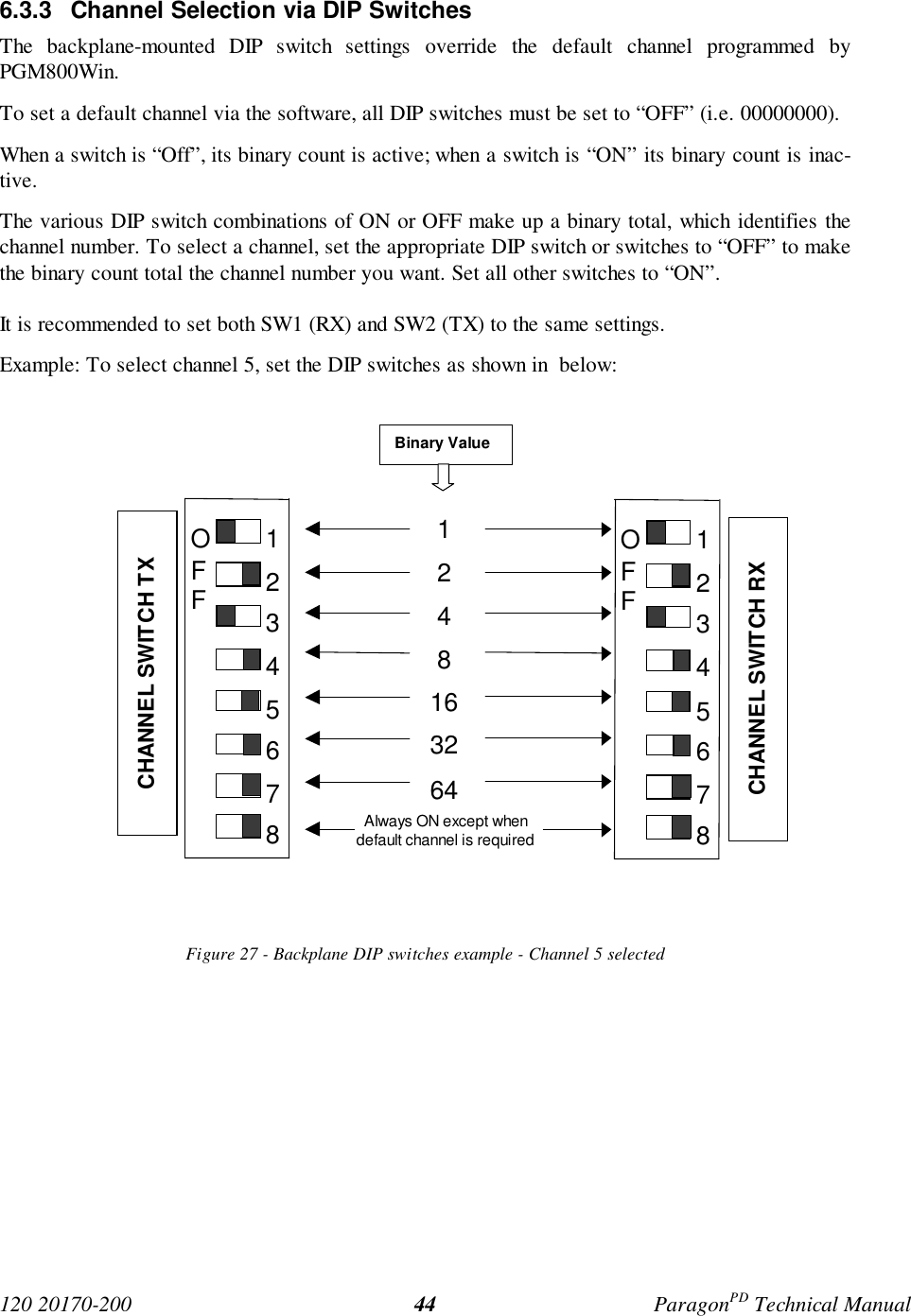
![120 20170-200 ParagonPD Technical Manual214.4.2 Configuration from a FileLoading a configuration from a file to a BDLCPDis useful to:• Restore the operating characteristics of aunit (Requires intervention with technicalsupport.)• Carry out field updates using Dataradiosystem engineering supplied diskette(s).Warning: Do NOT make any change to thesefiles unless called for in the trouble-shootingsection of this manual or by Dataradio’s SystemEngineering or Technical Support departments.Changing unknown parameters may render unitinoperative.4.4.2.1 “Put From” buttonAfter communication linking is established usingthe Connect button:1- Press the Put From button on the button bar.The program selects the bt2 filter file.2- In the opened “File, Put From” window, lo-cate the drive, directory and file name of therelevant file.• This may be a configuration saved ear-lier from a unit.• It can also be from a Dataradio (factoryor system engineering) diskette.4- Select the appropriate file5- Press the “OK” button. The status bar re-ports: “[filename] is downloading into unit”and up to 30 seconds later displays: “All pa-rameters are saved. Apply Station Reset totake effect!”.6- Press the “Station Reset” button (unit willbeep). See the next paragraph for details.4.4.2.2 “Station Reset” buttonPress the Station Reset button as a last step afterdoing a “Put From”. This action has the sameeffect as when pressing the membrane switch“Reset“ (see section 3.2.1.1.1 on page 12 fordetails). Causes downloaded parameters from afile or diskette to take effect in the connectedunit.Pressing Station Reset is not required after doingany Comments or Password configuration changeas these have their own Put Comments and PutPassword buttons.Station Reset does not break the connection.4.4.3 Special FunctionsThe following RIS fields and buttons are used togather specific information concerning the con-nected BDLCPD:• Banner field• “i” button• Comments field and Put Comments button• Password and Put Password button4.4.3.1 Banner Field and “i” buttonThis field displays a string made up of the serialnumber of the connected unit followed by thefirmware(s) used and their version number.Format For ParagonPD model is: [on-air address]:firmware 1 name, its version #,firmware 2 name, its version # (where name 1 isfor DSP and name 2 is for the main cpu). ParagonPD's firmware(s) resides in flashEPROM and are designed to allow field up-grades.When contacting your supplier, give the full ban-ner string and the version of the RIS used. Youwill find the version number in the “About” win-dow. To open it, click the lower left square but-ton (with a lowercase letter “i” in it).The Banner field is blank prior to establishing alink with the equipment using the Connect button.4.4.3.2 Comments1- Type comments directly in the “Comments”field. These can be text up to 24 characters.](https://usermanual.wiki/CalAmp-Wireless-Networks/BDD4T881.Annex-A-technical-manual-preliminary/User-Guide-127714-Page-28.png)
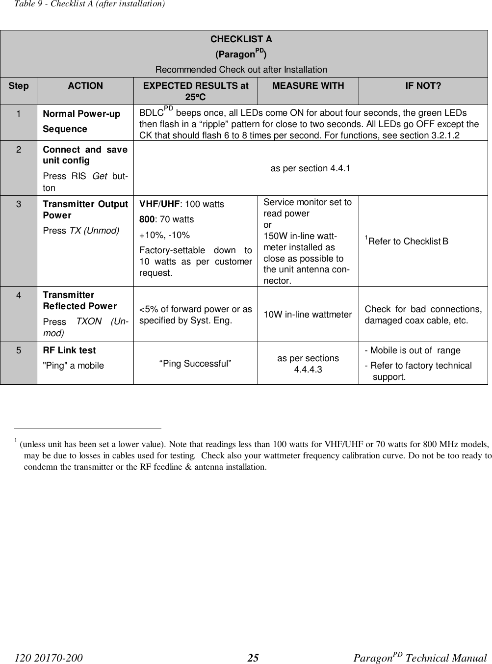
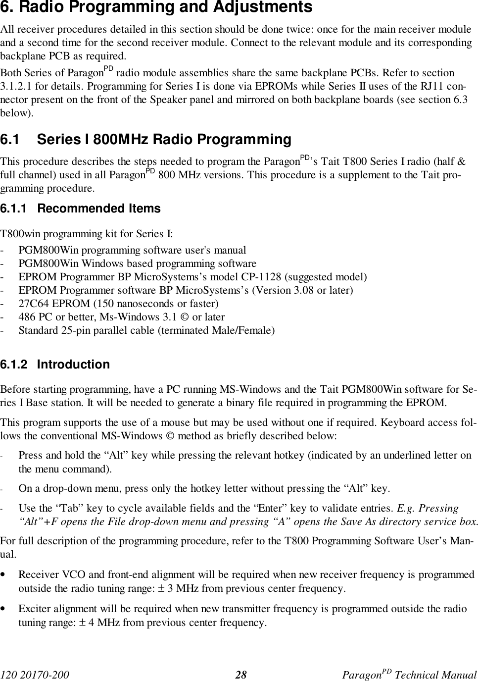

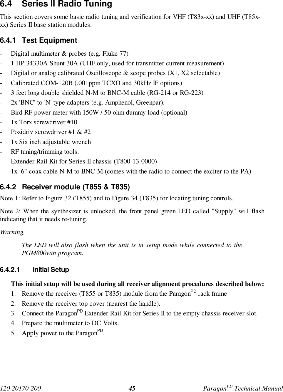
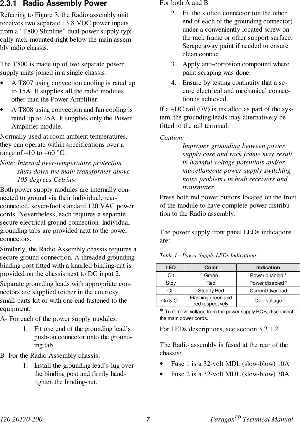
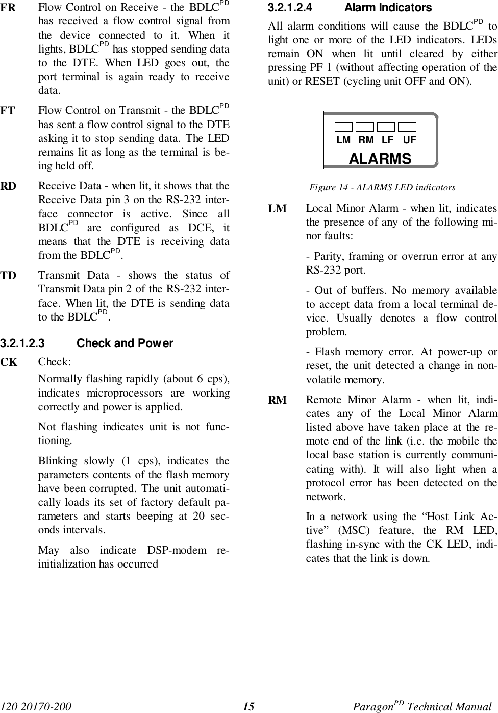
![120 20170-200 ParagonPD Technical Manual57Appendix 1 - ParagonPD Deviation adjust1. Using the RIS, press TX ON (Modulated) and record deviation level as read on the IFR.2. Using Windows Notepad, Edit the .bp2 file named with the corresponding BDLCPD serialnumber (e.g. abcd.bp1). “Save as” to another file name and keep it in case something goeswrong while changing a parameter.3. Locate the line labeled “Dev0 Par85=” and record the value beside the “=” sign. This is thecorresponding parameter value to the deviation read in step 1.4. Apply the following formula to determine the new parameter value to be set:(New Par85 value) = [(initial Par85 value) X (target deviation) / (deviation read)] + 25. Change the value in the file, “Save as” using the BDLCPD serial number file name.6. Run the RIS again and do a “Put From”. From the opened window, select the file that you justmade the change to and then press “OK”7. Again, check deviation level while pressing TX ON (Modulated). If fine-tuning of Par90 valueis still required, Edit the file again and re-do step 5 by changing directly the Par85 value by 1or 2 up or down.8. Re-check deviation level. If the level is now correct, press Stationreset to make the changepermanent.](https://usermanual.wiki/CalAmp-Wireless-Networks/BDD4T881.Annex-A-technical-manual-preliminary/User-Guide-127714-Page-64.png)