CalAmp Wireless Networks BDP3-CRE800 70W Power Amplifier CRE 800 User Manual

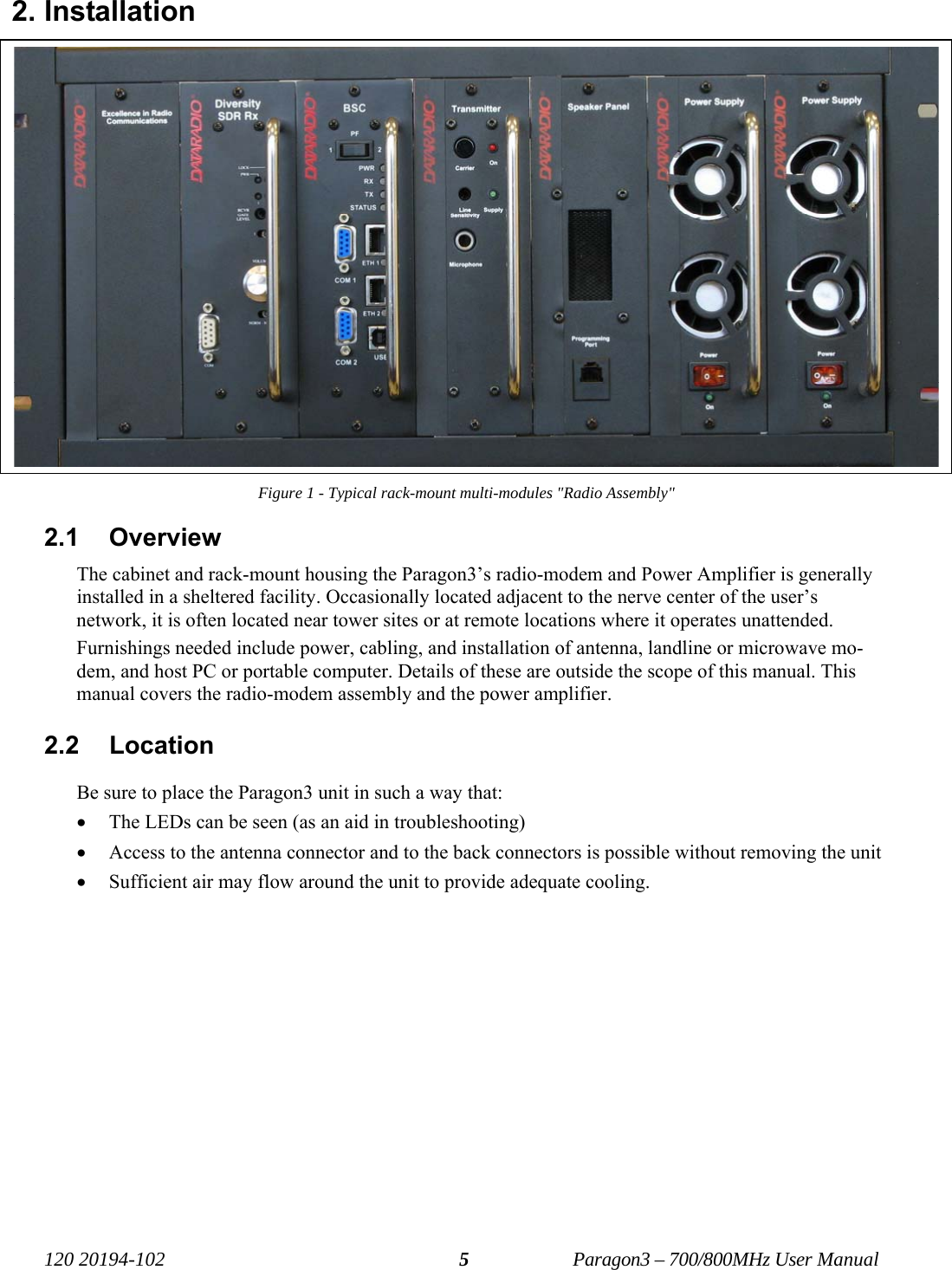
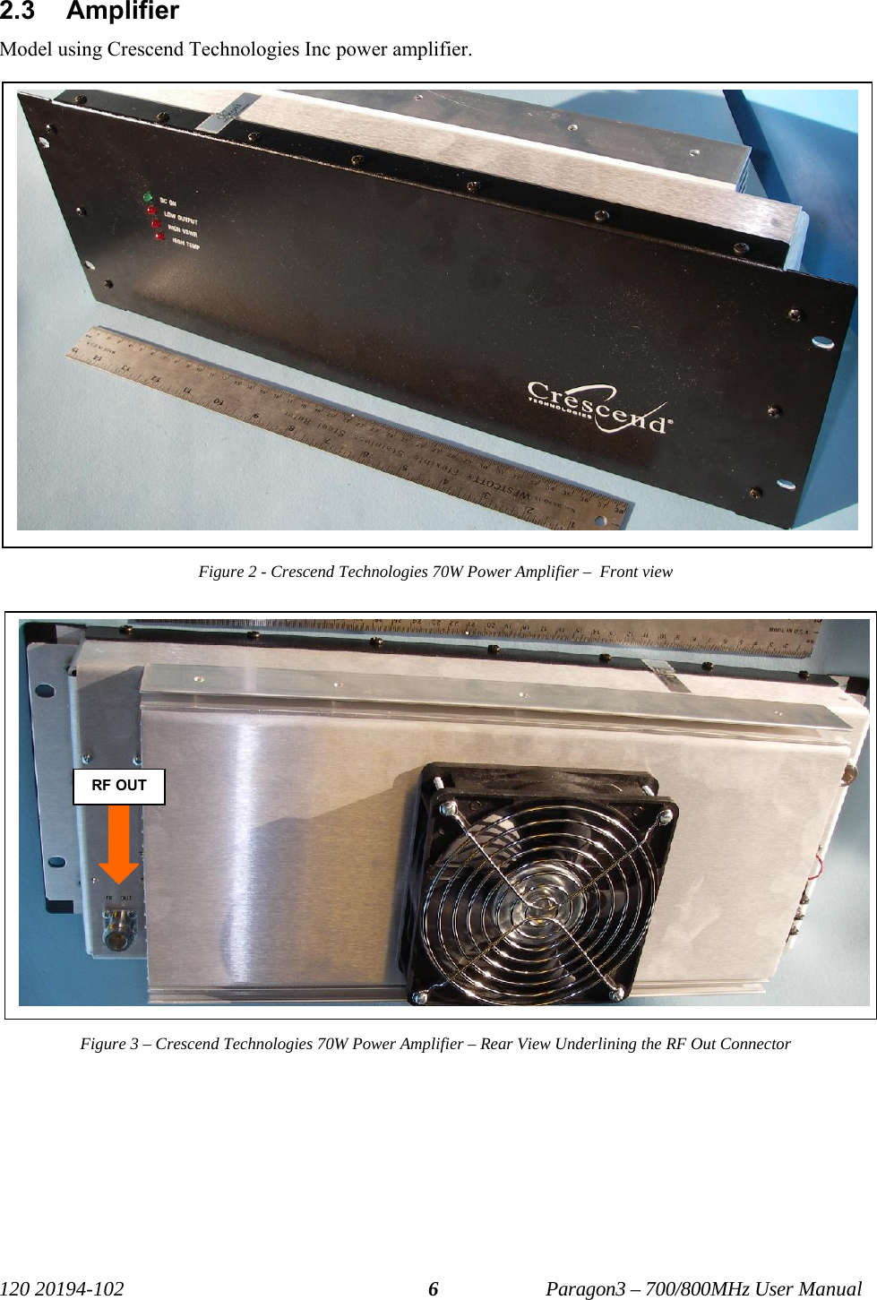
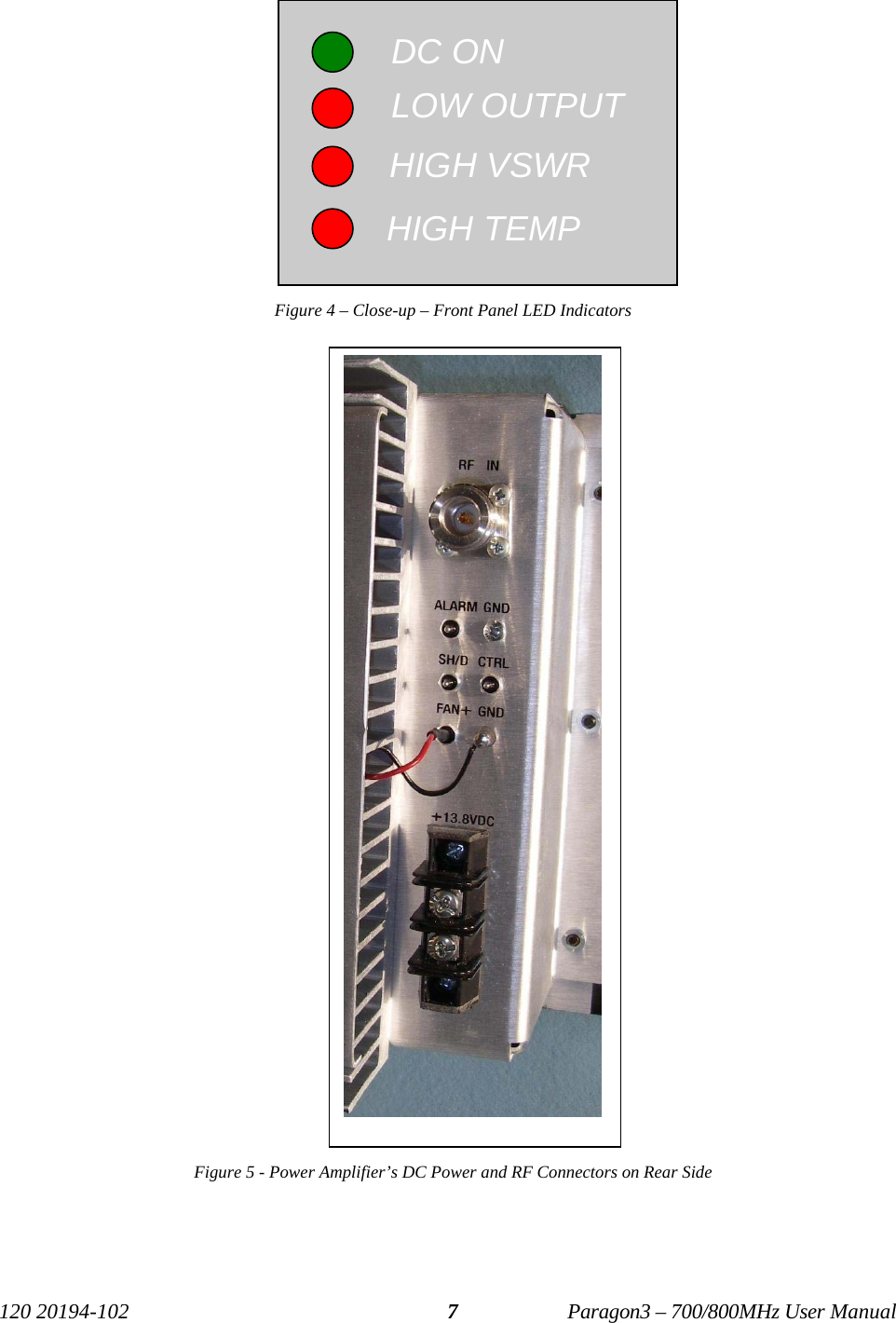
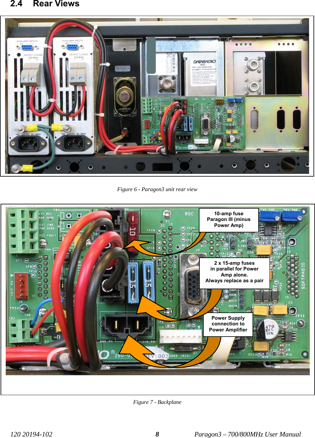
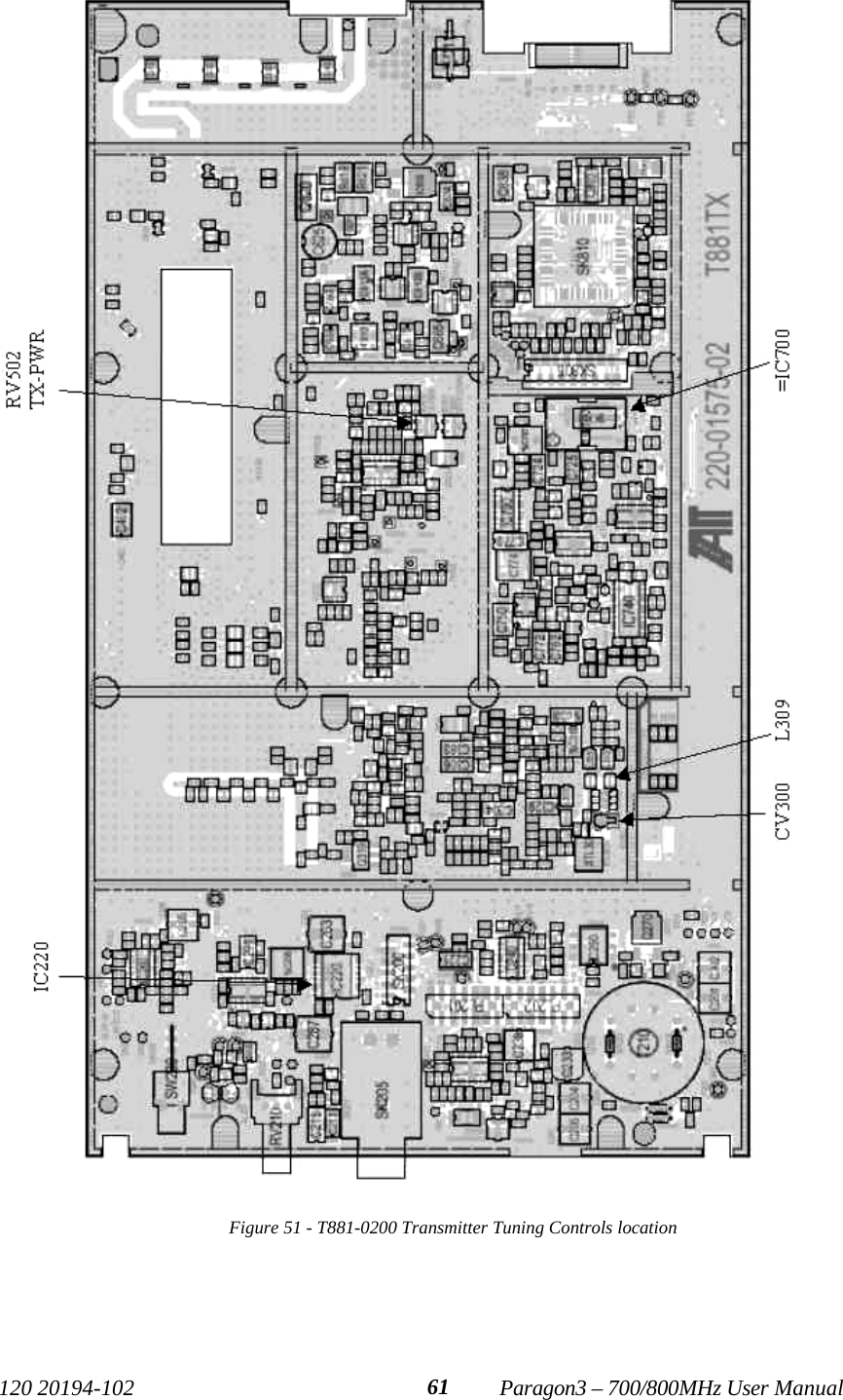
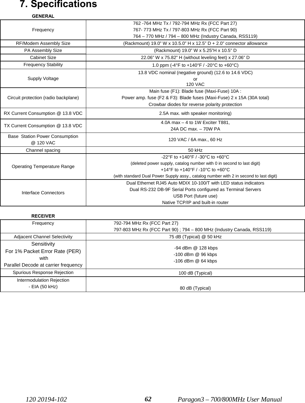
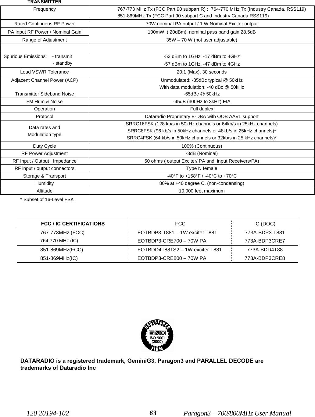
CALAMP WIRELESS NETWORKS INC. 70W Power Amplifier CRE 800

User Manual

Paragon3 (700/800MHz)  Data Base Station (With Crescent 70W PA) User Manual  Version 1.00  Preliminary – For FCC / IC     The entire contents of this manual are copyright 2007 by DATARADIO Inc. Copyright DATARADIO Inc. April 2007 Part no.: 120 20194-102 Preliminary
  120 20194-102   Paragon3 – 700/800MHz User Manual ii  1. PRODUCT OVERVIEW...................................................................................................................................1 1.1 INTENDED AUDIENCE ........................................................................................................................................1 1.2 GENERAL DESCRIPTION ....................................................................................................................................1 1.2.1 Features...................................................................................................................................................2 1.2.2 Configuration...........................................................................................................................................2 1.3 FACTORY TECHNICAL SUPPORT ........................................................................................................................3 1.4 PRODUCT WARRANTY.......................................................................................................................................4 1.5 REPLACEMENT PARTS .......................................................................................................................................4 1.5.1 Factory Repair.........................................................................................................................................4 1.6 PACKAGING.......................................................................................................................................................4 2. INSTALLATION................................................................................................................................................5 2.1 OVERVIEW ........................................................................................................................................................5 2.2 LOCATION .........................................................................................................................................................5 2.3 AMPLIFIER.........................................................................................................................................................6 2.4 REAR VIEWS .....................................................................................................................................................8 2.5 ELECTRICAL ......................................................................................................................................................9 2.5.1 Paragon3 Assembly Power......................................................................................................................9 2.5.1.1 Standard Power Supply Configuration............................................................................................................ 9 2.5.1.2 Backplane Fuses............................................................................................................................................ 10 2.6 POWER AMPLIFIER ..........................................................................................................................................10 2.7 ANTENNA ........................................................................................................................................................11 2.7.1 Overview................................................................................................................................................11 2.7.2 Cabling and Connection........................................................................................................................11 2.8 COMPLETING THE PHYSICAL INSTALLATION. ..................................................................................................11 2.9 CHECKING OUT NORMAL OPERATION .............................................................................................................11 3. OPERATING DESCRIPTION........................................................................................................................12 3.1 RADIO ASSEMBLY ...........................................................................................................................................12 3.1.1 Diversity SDR RX Module .....................................................................................................................12 3.1.2 1W Transmitter module .........................................................................................................................13 3.1.3 70W Power Amplifier ............................................................................................................................13 3.1.4 BSC module ...........................................................................................................................................14 3.1.5 Speaker panel.........................................................................................................................................14 3.1.6 Power Supply Modules ..........................................................................................................................15 3.1.6.1 Power Supply Rear Connections................................................................................................................... 16 3.1.7 Radio Backplane Assembly....................................................................................................................17 4.  OPERATION & CONFIGURATION ............................................................................................................18 4.1 BROWSER-BASED SETUP AND STATUS ............................................................................................................18 4.2 DEFAULT IP SETTINGS ....................................................................................................................................18 4.2.1 Ethernet Interface 1 (DATA)..................................................................................................................18 4.2.2  Ethernet Interface 2 (SETUP)................................................................................................................18 4.2.3 RF Interface...........................................................................................................................................18 4.3 IP NETWORK SETTINGS ...................................................................................................................................19 4.3.1  IP Network Settings (with Host) ............................................................................................................19 4.3.2  IP Network Settings (with Router).........................................................................................................19 4.4 LAN SETUP.....................................................................................................................................................20 4.5 LOGIN SCREEN ................................................................................................................................................20 4.5.1 Initial Installation Login........................................................................................................................21 4.6 INTERFACE ......................................................................................................................................................21 4.6.1  Apply, Cancel, Save Config, and Reset Unit Buttons & Help Icon........................................................22 4.7 ADVANCED IP SETTINGS .................................................................................................................................23 4.7.1 Unit Identification and Status................................................................................................................23 4.7.2 Setup (Basic)..........................................................................................................................................24 4.7.2.1 Setup (Basic) ► General .............................................................................................................................. 24 4.7.2.2 Setup (Basic) ► Basic IP Configuration....................................................................................................... 24 4.7.2.3 Setup (Basic) ► Serial Ports Setup............................................................................................................... 25
  120 20194-102   Paragon3 – 700/800MHz User Manual iii4.7.3 Setup (Advanced)...................................................................................................................................26 4.7.3.1 Setup (Advanced) ► LAN (IP) .................................................................................................................... 26 4.7.3.2 Setup (Advanced) ► RF (IP)........................................................................................................................ 27 4.7.3.3 Setup (Advanced) ► Roaming ..................................................................................................................... 28 4.7.3.4 Setup (Advanced) ► IP Services Setup........................................................................................................ 29 4.7.3.5 Setup (Advanced) ► IP addressing modes................................................................................................... 30 4.7.3.6 Setup (Advanced) ► IP Optimization & Tuning.......................................................................................... 31 4.7.3.7 Setup (Advanced) ► Time Source ............................................................................................................... 32 4.7.3.8 Setup (Advanced) ► Ethernet (PHY)........................................................................................................... 33 4.7.4 Security..................................................................................................................................................34 4.7.4.1 Security ► Password and Encryption Control.............................................................................................. 34 4.7.4.2 Security ► Access Control........................................................................................................................... 35 4.7.5 Statistics.................................................................................................................................................36 4.7.5.1 Statistics ► TCP/IP ...................................................................................................................................... 36 4.7.5.2 Statistics ► Airlink Statistics ....................................................................................................................... 37 4.7.5.3 Statistics ► Interfaces .................................................................................................................................. 38 4.7.6 Maintenance ..........................................................................................................................................39 4.7.6.1 Maintenance ► Ping Test............................................................................................................................. 39 4.7.6.2 Maintenance ► Radio Info........................................................................................................................... 40 4.7.6.3 Maintenance ► Unit Configuration Control................................................................................................. 41 4.7.6.4 Maintenance ► Package Control.................................................................................................................. 42 4.7.6.5 Maintenance ► RSSI Table.......................................................................................................................... 42 4.7.7 OOB Data..............................................................................................................................................43 4.7.7.1 OOB Data ► Out of Band ............................................................................................................................ 43 4.7.8 Remote Table.........................................................................................................................................44 4.7.9 Radio......................................................................................................................................................45 4.7.9.1 Radio ► RF Tests......................................................................................................................................... 45 4.7.10 Help...................................................................................................................................................46 5. TROUBLE-SHOOTING AND TESTING......................................................................................................47 5.1 EQUIPMENT REQUIRED....................................................................................................................................47 5.2 RECOMMENDED CHECKS.................................................................................................................................47 5.3 ADDITIONAL TEST DETAILS .............................................................................................................................50 5.3.1 Carrier Deviations.................................................................................................................................50 5.3.2 Windows/Unix Tools..............................................................................................................................51 5.3.3 Network Connectivity.............................................................................................................................51 5.3.4 Configuration Information.....................................................................................................................51 5.3.5 Statistics Information.............................................................................................................................52 5.4 FIRMWARE UPGRADING ..................................................................................................................................53 5.4.1 Procedure ..............................................................................................................................................53 5.4.1.1 File Integrity Failure ..................................................................................................................................... 54 6.  RADIO PROGRAMMING AND ADJUSTMENTS......................................................................................55 6.1 T881-10 RADIO TRANSMITTER PROGRAMMING ..............................................................................................55 6.1.1 Recommended Items ..............................................................................................................................55 6.1.2 T881-10 Module Programming .............................................................................................................55 6.1.3 Channel Selection via DIP Switches......................................................................................................57 6.2 TRANSMITTER RADIO TUNING ........................................................................................................................58 6.2.1 Test Equipment ......................................................................................................................................58 6.2.2 Transmitter Module (T881-10-xxxx)......................................................................................................58 6.2.2.1 Initial Setup................................................................................................................................................... 58 6.2.2.2 Synthesizer Alignment.................................................................................................................................. 58 6.2.2.3 Low-Frequency Balance Adjustment............................................................................................................ 59 6.2.2.4 TX Frequency Error Adjustment................................................................................................................... 60 6.2.2.5 Exciter Power Output.................................................................................................................................... 60 7. SPECIFICATIONS ..........................................................................................................................................62  FIGURE 1 - TYPICAL RACK-MOUNT MULTI-MODULES "RADIO ASSEMBLY" ....................................................................5 FIGURE 2 - CRESCEND TECHNOLOGIES 70W POWER AMPLIFIER – REAR VIEW – FRONT VIEW.......................................6 FIGURE 3 – CRESCEND TECHNOLOGIES 70W POWER AMPLIFIER – REAR VIEW..............................................................6 FIGURE 4 – CLOSE-UP – FRONT PANEL LED INDICATORS (WHITE LETTERS ON BLACK PANEL) .....................................7
  120 20194-102   Paragon3 – 700/800MHz User Manual ivFIGURE 5 - POWER AMPLIFIER’S DC POWER AND RF CONNECTORS ..............................................................................7 FIGURE 6 - PARAGON3 UNIT REAR VIEW .........................................................................................................................8 FIGURE 7 - BACKPLANE..................................................................................................................................................8 FIGURE 8 - MAXI-FUSE.................................................................................................................................................10 FIGURE 9 - RECEIVER MODULE .....................................................................................................................................12 FIGURE 10 - 1W EXCITER MODULE...............................................................................................................................13 FIGURE 11 - BSC MODULE............................................................................................................................................14 FIGURE 12 - SPEAKER MODULE ....................................................................................................................................14 FIGURE 13 - T-809 POWER SUPPLY MODULE ...............................................................................................................15 FIGURE 14 - T809 REAR PANEL ....................................................................................................................................16 FIGURE 15 - RADIO BACKPLANE ASSEMBLY ................................................................................................................17 FIGURE 16 - IP NETWORK SETTINGS IN ROUTER MODE (WITH HOST) ..........................................................................19 FIGURE 17 - IP NETWORK SETTINGS IN ROUTER MODE (WITH ROUTER)......................................................................19 FIGURE 18 - ENTER NETWORK PASSWORD SCREEN – ETH1 DATA PORT SHOWN .........................................................20 FIGURE 19 - WEB USER INTERFACE – WELCOME SCREEN............................................................................................21 FIGURE 20 - WEB USER INTERFACE..............................................................................................................................22 FIGURE 21 - UNIT IDENTIFICATION AND STATUS ..........................................................................................................23 FIGURE 22 - SETUP (BASIC) – GENERAL SETUP ............................................................................................................24 FIGURE 23 - SETUP (BASIC) – BASIC IP CONFIGURATION.............................................................................................24 FIGURE 24 - SETUP (BASIC) – SERIAL PORTS SETUP.....................................................................................................25 FIGURE 25 - ADVANCED IP CONFIGURATION - LAN (IP) .............................................................................................26 FIGURE 26 - ADVANCED IP CONFIGURATION - RF (IP) ................................................................................................27 FIGURE 27 - ADVANCED IP CONFIGURATION – ROAMING ............................................................................................28 FIGURE 28 - ADVANCED IP CONFIGURATION – IP SERVICES SETUP .............................................................................29 FIGURE 29 - ADVANCED IP CONFIGURATION – IP ADDRESSING MODES .......................................................................30 FIGURE 30 - ADVANCED IP CONFIGURATION - IP OPTIMIZATION & TUNING - OIP (ROUTER MODE)...........................31 FIGURE 31 - ADVANCED IP CONFIGURATION – TIME SOURCE......................................................................................32 FIGURE 32 - ADVANCED IP CONFIGURATION – ETHERNET (PHY) ...............................................................................33 FIGURE 33 - SECURITY – PASSWORD AND ENCRYPTION ...............................................................................................34 FIGURE 34 - SECURITY - ACCESS LIST ..........................................................................................................................35 FIGURE 35 - STATISTICS – TCP/IP................................................................................................................................36 FIGURE 36 - STATISTICS – AIRLINK – CHANNEL UTILIZATION .....................................................................................37 FIGURE 37 - STATISTICS – INTERFACES ........................................................................................................................38 FIGURE 38 - MAINTENANCE – PING TEST .....................................................................................................................39 FIGURE 39 - MAINTENANCE - RADIO INFORMATION.....................................................................................................40 FIGURE 40 - MAINTENANCE - UNIT CONFIGURATION CONTROL (INITIAL SCREEN) ......................................................41 FIGURE 41 – MAINTENANCE – PACKAGE CONTROL .....................................................................................................42 FIGURE 42 - MAINTENANCE – SPECTRUM.....................................................................................................................42 FIGURE 43 - OUT-OF-BAND .........................................................................................................................................43 FIGURE 44 - REMOTE TABLE ........................................................................................................................................44 FIGURE 45 - CONTROL - RF TESTS ...............................................................................................................................45 FIGURE 46 - HELP ICON ................................................................................................................................................46 FIGURE 47 – SAMPLE FTP PROGRAM............................................................................................................................54 FIGURE 48 - EXCITER SYSTEM INFOMATION SAMPLE ...................................................................................................56 FIGURE 49 - EXCITER CHANNEL INFORMATION SAMPLE ..............................................................................................56 FIGURE 50 – BACKPLANE DIP SWITCHES EXAMPLE – CHANNEL 5 SELECTED ...............................................................57 FIGURE 51 - T881-0200 TRANSMITTER TUNING CONTROLS LOCATION........................................................................61  TABLE 1 - ON-AIR DATA SPEEDS AND MODULATION TYPES ............................................................................................2 TABLE 2 - DIVERSITY SDR LEDS................................................................................................................................12 TABLE 3 - 70W POWER AMPLIFIER INDICATORS ..........................................................................................................13 TABLE 4 – TEST POINTS ...............................................................................................................................................17 TABLE 5 - CHECKLIST A (AFTER INSTALLATION) .........................................................................................................48 TABLE 6 - CHECKLIST B (GENERAL) ............................................................................................................................49 TABLE 7 – CARRIER DEVIATIONS .................................................................................................................................50
  120 20194-102   Paragon3 – 700/800MHz User Manual vWHAT'S NEW   History Draft for Crescent Amplifier based Paragon3 700/800MHz Version 1.00: Mars 2007 –Preliminary  • Initial release of Paragon3 700/800MHz radiomodem User Manual drafted from the manual of Paragon3 700MHz part No 120-20191-102. Version 1.01: 1st April 2007 –Preliminary  • Corrections on specifications at page 72. Version 1.02 10th April 2007 –Preliminary  • Added nominal bandwidth information on paragraph 3.1.3 “70W Power Amplifier“.
  120 20194-102   Paragon3 – 700/800MHz User Manual vi     About Dataradio For 25 over years, Dataradio has been a recognized and innovative supplier of advanced wireless data products and systems for mission-critical applications. Public safety organizations, utilities, local gov-ernment, water management, and other critical infrastructure operations depend on Dataradio to ensure that vital wireless data reaches the people who need it, when they need it most. From mobile data systems and radio modems, to analog radios and telemetry devices, Dataradio products are found at the heart of private wireless networks around the world.  www.dataradio.com Dataradio provides product brochures, case studies, software downloads, and product information on our website at http://www.dataradio.com  User Manual Statement Every effort is taken to provide accurate, timely product information in this user manual.  Product updates may result in differences between the information provided herein and the product shipped. The information in this document is subject to change without notice. About CalAmp Corp. CalAmp is a leading provider of wireless equipment, engineering services and software that enable any-time/anywhere access to critical information, data and entertainment content. With comprehensive capa-bilities ranging from product design and development through volume production, CalAmp delivers cost-effective high quality solutions to a broad array of customers and end markets. CalAmp is the leading supplier of Direct Broadcast Satellite (DBS) outdoor customer premise equipment to the U.S. satellite television market. The Company also provides wireless connectivity solutions for the telemetry and asset tracking markets, public safety communications, the healthcare industry, and digital multimedia delivery applications.   www.CalAmp.com For additional information, please visit http://www.calamp.com     DATARADIO and VIS are registered trademarks, GeminiG3, Paragon3, PARALLEL DECODE, and TRUSTED WIRELESS DATA are trademarks of Dataradio Inc
  120 20194-102   Paragon3 – 700/800MHz User Manual viiDefinitions  Access Point  Communication hub for users to connect to a wired LAN. APs are important for providing heightened wireless security. AES  Advanced Encryption Standard (AES) - uses 128-bit encryption to secure data. Airlink   Physical radio frequency connections used for communications between units. ARP   Address Resolution Protocol – Maps Internet address to physical address. AVL  Automatic Vehicle Location. Optional feature that involves using GPS (Global Positioning System) signals from the mobile unit by the Host PC.  Backbone   The part of a network that connects most of the systems and networks together, and handles the most data. Bandwidth   The transmission capacity of a given device or network. Base  Designates products used as base stations in VIS systems. They currently include the Paragon family of products up to the Paragon3.  Browser   An application program that provides a way to look at and interact with all the in-formation on the World Wide Web. BSC  Base Station Controller - An async controller-modem designed for the radio base station in mobile systems. A component of Paragon3™ base station.  COM Port  RS-232 serial communications ports of the Paragon3 wireless radiomodem.  Cycle Mark   Signal transmitted on an E-DBA network that keeps the network synchronized.  Default Gateway   A device that forwards Internet traffic from your local area network. DHCP   Dynamic Host Configuration Protocol - A networking protocol that allows ad-ministrators to assign temporary IP addresses to network computers by "leasing" an IP address to a user for a limited amount of time, instead of assigning perma-nent IP addresses. DNS   Domain Name Server - translates the domain name into an IP address. Domain   A specific name for a network of computers. Dynamic IP Addr  A temporary IP address assigned by a DHCP server. E-DBA  Dataradio’s Enhanced Dynamic Bandwidth Allocation airlink protocol. Ethernet   IEEE standard network protocol that specifies how data is placed on and re-trieved from a common transmission medium. Firewall   A set of related programs located at a network gateway server that protects the resources of a network from users from other networks. Firmware   The programming code that runs a networking device. Fragmentation  Breaking a packet into smaller units when transmitting over a network medium that cannot support the original size of the packet. FTP   File Transfer Protocol - A protocol used to transfer files over a TCP/IP network. Gateway   A device that interconnects networks with different, incompatible communica-tions protocols. GeminiG3  High specs dual DSP mobile radiomodem with Dataradio Parallel Decode™ technology  HDX  Half Duplex. Data transmission that can occur in two directions over a single line, using separate Tx and Rx frequencies, but only one direction at a time. HTTP   HyperText Transport Protocol - The communications protocol used to connect to servers on the World Wide Web.
  120 20194-102   Paragon3 – 700/800MHz User Manual viiiIPCONFIG   A Windows 2000 and XP utility that displays the IP address for a particular net-working device. MAC  ADDRESS  Media Access Control - The unique address that a manufacturer assigns to each networking device. NAT   Network Address Translation - NAT technology translates IP addresses of a local area network to a different IP address for the Internet. Network   A series of computers or devices connected for the purpose of data sharing, stor-age, and/or transmission between users. Network speed  This is the bit rate on the RF link between units.  Node   A network junction or connection point, typically a computer or work station. OIP  Optimized IP – Compresses TCP and UDP headers, and filters unnecessary ac-knowledgments. This makes the most use of the available bandwidth. OTA  Over-The-Air - Standard for the transmission and reception of application-related information in a wireless communications system Paragon3 IP-based data radio base station used in mobile networks and designed specifi-cally to fit the needs of vehicular applications. Runs up to 128 kb/s Parallel Decode  Technology featuring dual receivers for added data decode sensitivity in multi-path and fading environments. Ping   Packet INternet Groper - An Internet utility used to determine whether a particu-lar IP address is online. PLC  Programmable Logic Controller. An user-provided intelligent device that can make decisions, gather and report information, and control other devices. Roaming  Movement of a wireless node (GeminiG3) amongst Multiple Access Points (Paragon3). GeminiG3 supports seamless roaming. Router   A networking device that connects multiple networks together. RS-232  Industry–standard interface for data transfer.  Smart Combining  Digital processing method used to combine “Spatial Diversity” signals to opti-mize performance. (See Parallel Decode) SRRCnFSK  Square Root Raised Cosine (n = level) Frequency Shift Keying. Type of fre-quency modulation of data signals performed by the Paragon3 radiomodem. Spatial Diversity  Composite information from independent diversity branches using antennas spaced apart is used with “Smart Combining” to minimize fading and other unde-sirable effects of multipath propagation. (See Parallel Decode) Static IP Address   A fixed address assigned to a computer or device that is connected to a network. Static Routing   Forwarding data in a network via a fixed path. Subnet Mask   An address code that determines the size of the network. Switch (Ethernet)  A data switch that connects computing devices to host computers, allowing a large number of devices to share a limited number of ports.  Sync   Data transmitted on a wireless network that keeps the network synchronized.  TCP/IP   Transmission Control Protocol/Internet Protocol - A set of instructions PCs use to communicate over a network. Telnet   A user command and TCP/IP protocol used for accessing remote PCs. TFTP   Trivial File Transfer Protocol - A version of the TCP/IP FTP protocol that has no directory or password capability. Topology   The physical layout of a network. Transparent  A transparent unit transmits all data without regard to special characters, etc. UDP   User Datagram Protocol - A network protocol for transmitting data that does not require acknowledgement from the recipient of the data that is sent.
  120 20194-102   Paragon3 – 700/800MHz User Manual ixUpgrade   To replace existing software or firmware with a newer version. URL   Universal Resource Locator - The address of a file located on the Internet. VIS  Vehicular Information Solutions. Dataradio’s name for a series of products spe-cially designed for mobile data. WINIPCFG   A Windows 98 and Me utility that displays the IP address for a particular net-working device.  WLAN   Wireless Local Area Network - A group of computers and associated devices that communicate with each other wirelessly.
  120 20194-102   Paragon3 – 700/800MHz User Manual 11. PRODUCT OVERVIEW This document provides information required for the setting up, operation, testing and trouble-shooting of the Dataradio® Paragon3™ radio-modem base station.  1.1 Intended Audience This document is intended for engineering, installation, and maintenance personnel. 1.2 General Description The Paragon3 radio base station is a factory-integrated industrial-grade IP-based data product used in mobile networks and is designed specifically to fit the needs of vehicular applications. The 700MHz version features diversity Software Defined Radio (SDR) receivers for added data decode sensitivity in multi-path and fading environments. When used with Dataradio’s state-of-the-art GeminiG3 mobile IP data solution, the system delivers unequaled high-speed data performance and unmatched effective throughput.  All Paragon3 models are supplied in a rackmount configuration that includes: • A Paragon3 full-duplex radio-modem assembly that includes a Next generation high-speed Dataradio third generation “Base Station Controller” module (BSC) fitted in the radio chassis assembly.  • A 70W power amplifier (model P8-R1J1-C5 OR P8-R1K1-C5) manufactured by Crescend Technologies Inc. supplied in a stand-alone rackmount configuration. It is DC-powered by the Paragon3 unit. • Duplexer and backup power units are custom furnished items.  • Wire line modem(s) are optional items.  • Laptop PC and its application software are user-supplied items.
  120 20194-102   Paragon3 – 700/800MHz User Manual 21.2.1 Features • Parallel Decode (PD) technology featuring a diversity SDR receiver module for added decode sensitivity in multi-path and fading environments. • Fully IP-based product line, using an optimized IP layer that reduces IP overhead for the RF link • Sophisticated dual DSP-based modem design provides added system performance, fewer retries and more effective throughput. • 700MHz / 50 kHz and 800MHz/25kHz channels for the Public Safety band of operation:  767-773 MHz TX and 851-869 MHz TX  • Full duplex operation  • Base Station with 70W RF Power Amplifier (user adjustable from 35W) • On-air data speeds and modulation types supported: Table 1 - On-air data speeds and modulation types Modulation type  Channel spacing – 25 kHz Channel spacing – 50 kHz SRRC4FSK 32 kb/s  64 kb/s SRRC8FSK 48 kb/s  96 kb/s SRRC16FSK 64 kb/s  128 kb/s  • Uses Dataradio’s Next generation high-efficiency Enhanced-DBA over-the-air protocol • Over-the-air compatible with GeminiG3 mobile products • Out-of-band signaling enables transmission of GPS reports with no effect on system performance. • Flash programmable firmware, including over-the-air programming capability  • Paragon3 units are factory-configured based on each customer’s network system requirements 1.2.2 Configuration Paragon3 units are factory-configured. Configuration changes or upgrades are WEB-based.
  120 20194-102   Paragon3 – 700/800MHz User Manual 3 1.3 Factory Technical Support The Technical Support departments of DATARADIO provide customer assistance on technical prob-lems and serve as an interface with factory repair facilities. They can be reached in the following ways: For Canada and International customers: DATARADIO Inc. 5500 Royalmount Ave, suite 200 Town of Mount Royal Quebec, Canada H4P 1H7 Technical support hours: Monday to Friday 9:00 AM to 5:00 PM, Eastern Time phone: +1 514 737-0020 fax:   +1 514 737-7883   Email address: support@dataradio.com or For U.S. customers:  DATARADIO Corp. 6160 Peachtree Dunwoody RD., suite C-200 Atlanta, Georgia 30328 Technical support hours: Monday to Friday 9:00 AM to 5:00 PM, Eastern Time phone:  1 770 392-0002 fax:   1 770 392-9199 Email address: drctech@dataradio.com
  120 20194-102   Paragon3 – 700/800MHz User Manual 41.4 Product Warranty Warranty information may be obtained by contacting your sales representative. 1.5 Replacement Parts This product is usually not field-serviceable, except by the replacement of individual radio modules. Specialized equipment and training is required to repair logic, modem boards, and radio modules. Contact Technical Support for service information before returning equipment. A Technical Support representative may suggest a solution eliminating the need to return equipment. 1.5.1 Factory Repair When returning equipment for repair, you must request an RMA (Returned Material Authorization) number. The Tech Support representative will ask you several questions to clearly identify the prob-lem. Please give the representative the name of a contact person, who is familiar with the problem, should a question arise during servicing of the unit. Customers are responsible for shipping charges for returned units. Units in warranty will be repaired free of charge unless there is evidence of abuse or damage beyond the terms of the warranty. Units out of warranty will be subject to service charges. Information about these charges is available from Technical Support. 1.6 Packaging Each Paragon3 – 700/800MHz product normally leaves the factory packaged as follows: • A Dataradio base station “Radio-modem assembly”. • A rackmount 70W power amplifier assembly. • Two standard seven-foot 120VAC power cord.  • DC power harness to connect the radio assembly to the power amplifier rackmount assembly.  • Co-ax cable to connect the Exciter module to the power amplifier. Frequently, Paragon3 product components are field-assembled prior to customer delivery.  The cabinetry may then be supplied in one of several custom rack-mount configurations that may also in-clude fan, backhaul modems, duplexer/filters/combiners, and ancillary equipment.  If damage has occurred to the equipment during shipment, file a claim with the carrier immediately.
  120 20194-102   Paragon3 – 700/800MHz User Manual 52. Installation Figure 1 - Typical rack-mount multi-modules "Radio Assembly" 2.1 Overview The cabinet and rack-mount housing the Paragon3’s radio-modem and Power Amplifier is generally installed in a sheltered facility. Occasionally located adjacent to the nerve center of the user’s network, it is often located near tower sites or at remote locations where it operates unattended. Furnishings needed include power, cabling, and installation of antenna, landline or microwave mo-dem, and host PC or portable computer. Details of these are outside the scope of this manual. This manual covers the radio-modem assembly and the power amplifier. 2.2 Location Be sure to place the Paragon3 unit in such a way that: • The LEDs can be seen (as an aid in troubleshooting) • Access to the antenna connector and to the back connectors is possible without removing the unit  • Sufficient air may flow around the unit to provide adequate cooling.
  120 20194-102   Paragon3 – 700/800MHz User Manual 62.3 Amplifier Model using Crescend Technologies Inc power amplifier. Figure 2 - Crescend Technologies 70W Power Amplifier –  Front view Figure 3 – Crescend Technologies 70W Power Amplifier – Rear View Underlining the RF Out Connector  RF OUT
  120 20194-102   Paragon3 – 700/800MHz User Manual 7 Figure 4 – Close-up – Front Panel LED Indicators Figure 5 - Power Amplifier’s DC Power and RF Connectors on Rear Side       DC ON LOW OUTPUTHIGH VSWR HIGH TEMP
  120 20194-102   Paragon3 – 700/800MHz User Manual 82.4 Rear Views  Figure 6 - Paragon3 unit rear view Figure 7 - Backplane   Power Supply connection to Power Amplifier 10-amp fuse Paragon III (minus Power Amp) 2 x 15-amp fuses in parallel for Power Amp alone. Always replace as a pair
  120 20194-102   Paragon3 – 700/800MHz User Manual 9 2.5 Electrical Standard 120 VAC electrical power is required. It should be capable of providing at least 10A to power Paragon3 unit (<6A) and ancillary equipment. 2.5.1  Paragon3 Assembly Power Two distinct power configurations (rear views) are shown in the preceding pages. They are: • Paragon3 Base Station Standard Assembly. This configuration is described in paragraph 2.5.1.1 below. • Paragon3 Base Station Assy. with 3rd party DC supply.  This configuration illustrates typical wiring variation required when using both a third-party power supply and an optional DC-powered BSC setup. Refer to Dataradio System Engineering for further details. 2.5.1.1 Standard Power Supply Configuration The Radio assembly unit receives 13.8 VDC power inputs from two “T809 ” power supply modules powered at 120 VAC. Normally used at room ambient temperatures, it can operate within its specifi-cations over a range of –10 to +60 °C. Note: Internal over-temperature protection shuts down the main transformer above 105° Celsius. Both power supply modules are internally connected to ground via their individual, rear-connected, seven-foot standard 120 VAC power cords. The Radio Assembly chassis requires a secure ground connection. A threaded grounding binding post fitted with a knurled binding-nut is provided on the chassis next to DC input 2.  • For the Radio Assembly chassis, install the grounding lead’s lug over the binding post and firmly hand-tighten the binding-nut. • If a –DC rail (0V) is installed as part of the system, the grounding leads may alternatively be fit-ted to the rail terminal. Caution: Improper grounding between power supply case and rack frame may result in harmful voltage poten-tials and/or miscellaneous power supply switching noise problems in both receivers and transmitter. 2.5.1.1.1  DC Power Supply Connection & Torque Settings Warning: Securing the DC Power Supply cable into the DC connector to provide a good electrical connection is essential. Over time, the wires tend to compress in the DC connector result-ing in an increasingly poorer connection. Consequently, as high current is drawn, the connector heats up increasing the resistance thereby causing still more heat until the connector eventually burns up.  Although screws securing DC cables to the Power Supply terminals are tightened to the torque set-tings given below prior to new system delivery, they must be re-tightened as part of the commission-ing process and re-tightening is also part of the regular maintenance schedule. Prior to replacing a Power Supply module into an existing system, inspect the cable and re-terminate the DC wires if the strands have previously been twisted together or show any sign of damage. Cut the wire at the end of the insulation and then strip approximately .43 inch (11mm) of insula-tion off the cable. DO NOT TWIST THE WIRE STRANDS. Insert the DC cable into the screw terminal and tighten the screw to secure the cable as per the torque settings given below.
  120 20194-102   Paragon3 – 700/800MHz User Manual 10Torque Settings:  The manufacturer recommends torque setting all power supply terminal screws to a minimum of: • 1.5 Nm (or 13.28 In/lb or to 1.107 ft/lb) Note: Dataradio uses a Sturtuvan Richmond 29-pieces adjustable torque screwdriver model CAL36/4K. After tightening, pull on the cable to check the cable is secured tightly into the screw terminal. 2.5.1.1.2 Power Indications Both red-colored translucent power switches located on the front of the power supply modules illu-minate when AC power is available. Toggle both to ON to distribute power to the Radio Assembly and to the Power Amplifier. The LED immediately below the switches light green indicating normal DC power operation.  2.5.1.2 Backplane Fuses Blade fuses (Maxi-Fuse) are used on the Radio assembly backplane:  Dimensions – Inch (mm) Fuse Type  A B C Maxi-Fuse  1.15 (29.21)  1.35 (34.29)  .35 (8.89)  Fuse #  F1 F2 F3 Values 10A  15A*  15A* * Always replace the two 15A fuses as a pair.   Figure 8 - Maxi-Fuse 2.6 Power Amplifier Refer to Figure 5 on page 7 for the location of DC power and RF in and out connectors. Connect the T881 Tx module output to the power amplifier’s input using the set provided by Da-taradio (an RG223 cable with a 10dB attenuator). For the power amplifier output, Dataradio recommends a 50-ohm, low-loss, double-shielded grade RF cable such as RG214 or 1/4" Heliax.  Power adjustments cannot be made on the field without voiding the warranty.   Dataradio does not recommend setting an output lower than 35 watts. Allow a 60-minute warm-up period before setting power. Note: Although the T809-10 is a high efficiency switched mode power supply (PS), a consider-able amount of heat is generated during normal operation with the power amplifier (PA). While in use, ensure that an adequate flow of cooling air is able to circulate around the PS and the PA, and that the air intake vents on the rear and sides of the unit are not inadver-tently covered. Caution:  Do not operate this unit in a completely enclosed cabinet.
  120 20194-102   Paragon3 – 700/800MHz User Manual 112.7 Antenna 2.7.1 Overview Paragon3 unit commonly uses three antennas (one transmit and two receive) unless a duplexer is used with one of the receive antennas; then only two antennas would be needed. They should be mounted according to any guidelines supplied with the antennas. For antennas placement and spacing, consult System Engineering.  2.7.2  Cabling and Connection 1- Route good quality 50-ohm double-shielded coaxial cable(s) (e.g. RG-214 or Heliax) from the se-lected antenna position(s) to the Paragon3 Radio assembly. 2- Terminate the RX-1 (bottom) and RX-2 (top) cable-ends at the SDR module rear position with N-type connectors. 3- Similarly, terminate the TX cable-end at the Power Amp’s module rear position with an N-type connector. Caution:  When terminating RF cables use brand-name crimping tools (such as AMP, Jensen, Crimp-Master, etc…) of the correct size for the cable and type of connector used. Common pliers are NOT acceptable. 2.8  Completing the physical Installation. Paragon3 products are factory-configured to user’s requirements and are shipped ready to run.  After new installations: • Re-check that all connections are secure on the radio-modem assemblies (antennas, PC, power cords etc.) • Check that fuses are inserted. • Turn power supplies ON. You are now ready to check for normal operation (as per paragraph 2.9) and to run the Dataradio web interface (described in section 4) for testing or trouble-shooting.  Any change(s) to the settings must be done via files saved on diskette and loaded into the unit using the web interface program. 2.9  Checking out Normal Operation 1- Check that power is applied. 2- Check Radio assembly lights for proper operation as per section 3.1.1 3- Check for proper operation of the BSC’s LEDs. 4- Using the web interface program and an in-line wattmeter, check forward & reverse power to confirm main antenna installation. 5- Using the web interface, check the RF Data Link with a mobile that can be heard. If user application and mobiles are available, test the installation by going through a normal sequence of transmitting and receiving messages.
  120 20194-102   Paragon3 – 700/800MHz User Manual 123. Operating Description 3.1 Radio Assembly The Radio assembly component of each Paragon product is made up of high performance synthesized radio base station designed for single operation. The Radio Assembly’s modules are commonly installed in a standard, 19-inch wide rack frame.  The complement of modules is: • 1 x  SDR module • 1 x 1W Transmitter • 1 x BSC (controller-modem) • 1 x Speaker panel • 2 x Power Supplies • 1 x 70-Watt Power Amplifier 19” rackmount assembly 3.1.1  Diversity SDR RX Module The Diversity SDR Rx module front panel controls and indicators are: • RCVR GATE LEVEL  - Mute threshold adjustment. • 1 / 2 Switch – Manual selection of Channel 1 or 2 audio. • Monitor Volume – Audio level adjustment. Always set volume knob to minimum when not in use. • NORM-MON Switch – Manual selection between audio unmuted (continuous monitor) or when audio is above the manually adjusted mute threshold. • COM – For factory use.        Figure 9 - Receiver module  Table 2 - Diversity SDR LEDs Green   normal operation Amber   bootloader program running PWR LED Red   malfunction / reset Green   PLL locked LOCK LED  Red         PLL not locked Green   RF carrier signal on audio channel 1 is above manually adjusted mute threshold 1 LED  Off   RF carrier signal on audio channel 1 is below manually adjusted mute threshold Green   RF carrier signal on audio channel 2 is above manually adjusted mute threshold 2 LED  Off   RF carrier signal on audio channel 2 is below manually adjusted mute threshold    PWRRCVR GATE LEVEL 1 – 2 Switch Monitor Volume NORM-MON Switch LOCK12COM®DiversitySDR RxRCVRGATELEVELLOCKPWR1221VOLUMENORM - MONCOM
  120 20194-102   Paragon3 – 700/800MHz User Manual 133.1.2  1W Transmitter module The Exciter’s front panel controls and indicators are: • Carrier Switch - momentarily keys the transmitter ON while pressed (used for test purposes only). • On LED - is lit when transmitting • Line Sensitivity – not used. • Supply LED - is lit when DC power is applied. Fast Flashes when linked with PGM800Win. Slow Flashes indicates VCO (synthesizer) out of lock. Unequal Flashes indicates internal communication error. • Microphone Socket – not used.           Figure 10 - 1W Exciter module  3.1.3  70W Power Amplifier The power amplifier is maintenance free, only LED indications are provided for the user. The amplifier module has a large nominal bandwidth (500-1000MHz) designed platform. The units of the base station are customarily tuned to achieve a +/-0.1dB gain variance over the band of 764-776MHz (700MHz models) or 851-869MHz (800MHz model). Attempting to fix a faulty unit outside manufacturer’s premises can irreversibly damage it.  The 10dB attenuator of the connecting set must be attached at the input of the PA in order to adjust RF input to 100mW (+20dBm).  As per Industry Canada Radio Standard Specification #131, paragraph 5.3: “The manufacturer's rated output power of this equipment is for single carrier operation. It should not be used for multiple carrier operations.” Refer to Figure 4 on the page 7, for the locations of the indicators. Table 3 - 70W Power Amplifier indicators LED Function DC  ON  Lights green when power is applied LOW OUTPUT  Lights red when output RF power falls below threshold HIGH VSWR  Lights red when output VSWR exceeds 3:1  HIGH  TEMP  Lights red when temperature-based shutdown is triggered  Carrier Switch On LED Supply LED Line Sensitivity Microphone Socket ®ExciterCarrier OnLineSensitivitySupplyMicrophone
  120 20194-102   Paragon3 – 700/800MHz User Manual 143.1.4 BSC module The BSC's front panel connectors and indicators are: Green   Normal operation Amber   Step 2 in uMon boot-up – lights for <1 sec. PWR LED Red   Step 1 in uMon boot-up – lights for <1 sec. Green   Flashes for each data packets received RX LED  Red         Discard RX packet (factory-use) Green   Flashes for each data packets transmitted Amber  Flashes for each data packets transmitted  (check for lost Host connection) Red  Continuoulsy ON for TXON test (max. 20 secs.) Flashes ON for CWID key-up event TX LED Off   Check if in “AirLink down mode” Green   Flashes each time PF1 or PF2 is pressed STATUS  Amber  Flashes each second PF1 is kept pressed  Toggles “AirLink down mode” after 4 seconds  • 2x DE-9 RS-232 ports for setup and user data • 1X rocker switch ( positions PF 1 and 2) to select various test modes • 2x Ethernet ports – for setup and user data • 2x Ethernet LEDs (status & activity)  • USB port – reserved.  Figure 11 - BSC module  3.1.5 Speaker panel The speaker panel is fitted with a four-Ω speaker.  The RJ11 connector is used to allow programming the radio transmitter module (only) from the front of the unit via a programming lead.  If the speaker panel needs to be removed, a mirror programming port connec-tor is provided on the backplane.                Figure 12 - Speaker module  ®PWRTXBSCETH 2RXUSBETH 1COM 2COM 1STATUS® Speaker Panelprogrammingport
  120 20194-102   Paragon3 – 700/800MHz User Manual 153.1.6  Power Supply Modules Two switched mode pulse width modulated T-809 power supply modules are used but not connected in parallel. Both power supply units have an ON-OFF switch and an output voltage ad-just potentiometer (13.5 to 18 VDC). Their circuit protection features are: • Inrush current limiting • Over-current (short-circuit) - 37 to 48A constant current limiting - Reset = auto recovery • Over-voltage  - 18 to 21 VDC = shutdown - Reset = Power OFF and ON • Over-temperature - shutdown of output voltage - auto recovery with temperature reduction - temperature sensed on transistors and diodes Front Panel Indications Power Switch  Illuminates when the unit is connected to AC power and voltage is available ON LED   - Lights bright green when voltage output is normal - Lights faint green when module has entered over-current mode - Green LED is OFF, but power switch is ON indicates module has shut down due to over-temperature or over-voltage conditions. Figure 13 - T-809 Power Supply Module ® Power SupplyPowerOn
  120 20194-102   Paragon3 – 700/800MHz User Manual 163.1.6.1  Power Supply Rear Connections The rear panel connections are: • Auxiliary Inputs –  The DE-9 connector on the T809-10 rear panel provides access to the remote control of the power supply (reserved for future use). • Output Voltage Adjust –  The output voltage of the power supply can be increased (up to 18V approximately) to compensate for the voltage drop lost along the cable. Access the trim-pot through a small hole on the rear panel. To adjust the output voltage use a trimmer tool with a Phillips head or 3mm blade (do not use a standard flat blade screwdriver to make the ad-justment): • To increase the output voltage, turn the trim-pot clockwise. • To decrease the output voltage, turn the trim-pot counterclockwise. If the output voltage is increased on a power sup-ply operating at, or close to, full load, the power supply loading must be reduced accordingly or the module may overheat and shut down. • Feedthrough Terminal Block –  The DC Output Terminal block on the rear of the T809-10 is a Phoenix Contact HDFKV 10. This is a screw-type terminal connector that uses a cage mechanism to clamp the conductor(s). See section 2.5.1.1.1 for recommended torque settings. • Protective Bonding Terminal –  The Radio Assembly requires a secure ground connection. See section 2.5.1.1 for connection de-tails. • 120 VAC Connector –  Use the supplied 10A-rated IEC type power cord.    Figure 14 - T809 Rear panel AUXILIARY INPUTS OUTPUT 13.8 VDC 30A MAX -      + -    + 100-240 VAC 50/60Hz 1 9 Output voltage adjustFeedthrough terminal block 13.8 VDC output Negative (-)Positive (+) Protective bonding terminal NeutralLive  Earth
  120 20194-102   Paragon3 – 700/800MHz User Manual 173.1.7  Radio Backplane Assembly  Figure 15 - Radio Backplane Assembly Table 4 – Test Points Backplane Test Points Test   Pinout  Alternate Pinout  Ground    J-9 – Pin 14  JP1 – Pin 3  SINAD  RX1  J-9 – Pin 3  J-18 – Pin 1 SINAD  RX2  J-9 – Pin 4  J-19 – Pin 1  Distortion  RX1  J-9 – Pin 3  J-18 – Pin 1 Distortion  RX2  J-9 – Pin 4  J-19 – Pin 1  RSSI  RSSI 1  J-9 – Pin 1  J-18 – Pin 3 RSSI  RSSI 2  J-9 – Pin 2  J-18 – Pin 3  Power Amplifier 13.8 VDC Maxi-Fuse 10A  2 Maxi-Fuses 15A(Factory  calibration) 15-pin High DensityRJ-45 connector Used for  programming System 13.8 VDC Pin 1 F1 F3 F2 Fan Channel Selection J-9 J-18 Pin 1J-19 Pin 1JP1
  120 20194-102   Paragon3 – 700/800MHz User Manual 184. Operation & Configuration 4.1  Browser-Based Setup and Status A built-in web server makes configuration and status monitoring possible from any browser-equipped computer, either locally or remotely. Status, configuration, and online help are available without requiring special client software. Setup is password-protected to avoid tampering or unauthorized changes.  Both the configuration parameters and operating firmware can be updated remotely, even over the RF network itself, using the standard FTP protocol. 4.2  Default IP Settings • Paragon3 radio modem supports the Router (IP Forwarding) mode 4.2.1  Ethernet Interface 1 (DATA) • MAC:     00:0A:99:XX:YY:ZZ • IP ADDR:     192.168.202.1 • NETMASKS:   255.255.255.0 • Default Gateway:   0.0.0.0 • DHCP Client  Disabled • RIPv2   Disabled 4.2.2  Ethernet Interface 2 (SETUP) • MAC:     00:0A:99:XX:YY:ZZ + 1 • IP ADDR:     192.168.203.1 • NETMASKS:   255.255.255.0 • DHCP Server  Disabled • NAT   Disabled 4.2.3 RF Interface • MAC:     00:XX:YY:ZZ • IP ADDR:     10.XX:YY:ZZ • NETMASK:   255.0.0.0 • Compression Enabled • Encryption   Disabled
  120 20194-102   Paragon3 – 700/800MHz User Manual 194.3  IP Network Settings 4.3.1  IP Network Settings (with Host) Referring to Figure 16 below, set the Paragon3 base station. Set the “Data” port Eth1 IP addresses (for  “Setup” port set Eth2) and IP netmask of both Base and Mobile(s). Keep the RF IP setting as is, providing customer is not using the 10.0.0.0 IP network. Add routes in the Host (route add…) In the illustration, Host and PC are part of different IP subnet Figure 16 - IP Network Settings in Router Mode (with Host) 4.3.2  IP Network Settings (with Router) Referring to Figure 17 below, set the Paragon3 base station. Set the “Data” port Eth1 IP addresses (for    “Setup” port set Eth2) and IP netmask of both Base and Mobile(s). Figure 17 - IP Network Settings in Router Mode (with Router)  Paragon3 Base   SETUP:  Eth2 IP: 192.168.203.1 MASK: 255.255.255.0    RF IP: 10.0.0.1 MASK: 255.0.0.0 Mobile DHCP Server   RF IP: 10.0.0.2 MASK: 255.0.0.0   Eth1 IP: 192.168.201.1 MASK: 255.255.255.0 RF Network Host IP: 192.168.202.2 MASK: 255.255.255.0       route add 10.0.0.0 mask 255.0.0.0 192.168.202.1  PC DHCP Client  DATA: Eth1 IP: 192.168.202.1 MASK: 255.255.255.0  Paragon3 Base SETUP:  Eth1 IP: 192.168.203.1 MASK: 255.255.255.0         RF IP: 10.0.0.1 MASK: 255.0.0.0 Mobile DHCP Server NAT    RF IP: 10.0.0.2 MASK: 255.0.0.0    Eth1 IP: 192.168.201.1 MASK: 255.255.255.0 RF NetworkRouter IP: 192.168.202.2 MASK: 255.255.255.0 route add 10.0.0.0 mask 255.0.0.0 192.168.202.1 PC DHCP Client  DATA: Eth1 IP: 192.168.202.1 MASK: 255.255.255.0 Default Gateway: 192.168.202.2 Host
  120 20194-102   Paragon3 – 700/800MHz User Manual 20Keep the RF IP setting as is, providing customer is not using the 10.0.0.0 IP network. Enable RIPv2 on Base station In the illustration, Host and PC are part of different IP subnet. 4.4 LAN Setup On a PC running MS-Windows with an existing LAN connection, connect either to the ETH1 (Data) or to ETH2 (Setup)  RJ-45 input of the Paragon3 base station. 1. Click Start Î Settings Î Control Panel Î Network and Dial-up Connection 2. Click on the relevant Local Area Connection 3. On the Local Area Connection Status screen, click Properties 4. On the Local Area Connection Properties screen, scroll the List Box until “Internet Protocol (TCP/IP)” is highlighted, click Properties 5. On the Internet Protocol (TCP/IP) Properties screen, follow either method below: A) If using ETH2 (Setup LAN),  select “Obtain an IP address automatically”  B) Select “Use the following IP address” Î Enter 192.168.202.2 (if ETH2 enter 192.168.203.2) in the IP address field Î 255.255.255.0 in the Subnet mask ÎLeave the Default gateway blank. 6. Click the OK button Note: On computers running Windows 9X, reboot to complete the connection process. Steps above specifically apply to MS-Windows 2000. Modify as necessary for the OS you are running 4.5 Login Screen On the Address line of the Internet browser of your choice, type the factory-default IP addresses given to all Paragon3 radiomodem units: 192.168.20x.1 (where x is 2 for the ETH1 Data port and 3 for the ETH2 Setup port). Press Enter. The Enter Network Password screen opens. Figure 18 - Enter Network Password screen – ETH1 Data port shown  192.168.202.1
  120 20194-102   Paragon3 – 700/800MHz User Manual 214.5.1 Initial Installation Login For an initial installation, enter a User Name of 1 to 15 characters and the default Password ADMINISTRATOR (upper case letters). Click OK. The Web interface “Welcome” screen opens Figure 20. Figure 19 - Web User Interface – Welcome Screen For subsequent access to the Paragon3 unit, use the User Name and Password that you will have config-ured.  Notes: User Name field can be left blank. It only serves to identify the person gaining access.  Password is common and affects all User Name entries. 4.6 Interface The Paragon3 user interface (Figure 19) (Figure 20) is used to configure and view your network settings.  To navigate, use the top-level menus on the left, some of which expand to offer submenus, and display the first submenu in the right-hand frame. Click the current submenu entry to refresh the right-hand frame. The tables starting at section 4.7.1 below list action of each function. The interface main screen lists available selections for the selected menu or presents instructions. Notes:  Screen captures used throughout this document may vary from actual screens. At any time, click the Help Icon in the navigation pane to open a help text relating to the window being displayed.
  120 20194-102   Paragon3 – 700/800MHz User Manual 22 Figure 20 - Web User Interface 4.6.1  Apply, Cancel, Save Config, and Reset Unit Buttons & Help Icon  Several submenus have “Apply” and “Cancel” buttons.  The navigation area has “Save Config”, “Reset Unit” buttons and a Help icon.  If you “Apply” changes to any parameters marked  you will need to do a “Save Config” and a “Reset Unit”. Make an entry into a dialog box. When satisfied, click on Apply to temporarily apply the value(s) entered to the relevant parameter(s). If not satisfied, click on Cancel button to restore to the value(s) present be-fore a change was made. Note: Cancel command only affects the dialog boxes or radio buttons in the opened window. If needed, go to other submenu(s) and make more entries. Click Apply before leaving each window. When finished, click the Save Config button to make all changed entries permanent.  Notes: Failure to use the “Apply” command button before leaving a web page will result in the loss of tem-porarily entered selections, addresses, and values. Failure to use the “Save Config” command button before doing a Reset Unit will result in the loss of temporarily entered parameters.  If there are changes to be saved, saving occurs automatically. • Click on Save Config button: • If there are no changes to be saved, a window prompts user to confirm saving.  Click on “Reset Unit” button:  • If there are changes to be saved, a window prompts user to confirm resetting. • If there are no changes to be saved, resetting occurs automatically. A “Station Reset” 20-second timer counts down while the status reports: “Working…” When done, the status reports: “Ready”.
  120 20194-102   Paragon3 – 700/800MHz User Manual 234.7  Advanced IP Settings 4.7.1  Unit Identification and Status  Displays values that identify the unit and show its basic operating condition.  Figure 21 - Unit Identification and Status Item  Description Banner  Displays Paragon3 software revision information retrieved from the connected unit. Have this information handy if contacting Dataradio support. Station Name  Displays name of connected unit.  Configured under Setup Basic Î General Î Station Name  System ID  Displays System’s unique identification number Configured under Setup Basic Î General Î System ID Local Time  24-hour clock format display of the GMT time and date adjusted to the specified time zone.  Configured under Setup Advanced Î Time Source Î SNTP CWID Callsign  Continuous wave ID - Way of sending FCC license ID using Morse code. CWID Interval   Interval between CWID messages in minutes.  Zero = never.
  120 20194-102   Paragon3 – 700/800MHz User Manual 24 4.7.2 Setup (Basic) 4.7.2.1 Setup (Basic) ► General Used to set two basic operating fields on the connected unit. Figure 22 - Setup (Basic) – General Setup Item  Description Station Name  Station name identifier – Enter string up to forty characters in length System ID Factory default ID is zero. To prevent collision and to minimize interference from re-mote systems that may be present on the same frequency, Dataradio recommends changing the System ID to some other value unique to each network.  Upper limit is 255 4.7.2.2 Setup (Basic) ► Basic IP Configuration Sets the IP characteristics of the primary, or only, Ethernet port. Figure 23 - Setup (Basic) – Basic IP Configuration Item  Description Use fixed IP settings  Creates a fixed TCP/IP address connection. You may need to ask your network adminis-trator for the appropriate IP settings. ETH 1 IP Address Set to valid unique IP address for each individual unit.  Factory default is 192.168.202.1 for all Paragon3 units connected to their ETH1 port. For ETH2 configuration, see Setup Advanced Î LAN IP   ETH 1 Netmask  Set to valid IP netmask for each individual unit (may be same or different depending on customer’s IP network topology). Default Gateway  Set to valid Default Gateway.  May change for different groups or locations Use DHCP Client  Dynamic Host Configuration - Dynamically assigns an IP address ETH 1 IP Address ETH 1 Netmask Default Gateway These three read-only fields display the IP addresses obtained from the DHCP Server
  120 20194-102   Paragon3 – 700/800MHz User Manual 254.7.2.3 Setup (Basic) ► Serial Ports Setup The Paragon3 base station serial ports can be logically connected to local and remote services to aid in configuration and troubleshooting, or they can be connected to a remote Host application or even to the serial port of a remote unit. Figure 24 - Setup (Basic) – Serial Ports Setup Item  Description Enabled  Independent check boxes to activate COM-1 PORT and/or COM-2 PORT Speed  Select  300, 1200, 2400, 4800, 9600, 19200, 38400, 57600, 115200 Baud Rate Flow Control  Select None or CTS-based (RTU dependent) Connection Control  Select Permanent (3-wire) or Switched (DTR bringup/teardown) (RTU dependent) IP Gateway Service Select one of:  CLI Service (Command line interface) RS-232 connection to Host PC (Default = SETUP) Custom – Choosing Custom enables the IP Gateway Transport configuration  IP Gateway Transport  Available only if IP Gateway Service selection is Custom, choose the socket connection mode from the drop-down list box choices of TCP Server, TCP Client, or UDP. Local IP Address  Valid unicast or multicast IP address, including the local Loopback interface address.   Default local IP address is set to 0.0.0.0 and can be changed dynamically without a unit reset. Local IP Port For TCP Client and UDP socket connections, set to any value between 1 and 65535. For TCP Server socket connections, set to any value between 1 and 65535 but must not be set to one of the following values or fall within the following ranges of values: 20, 21, 23, 123, 520, 5002, 6254 to 6299, 7000 to 7100. Otherwise, the parameter configuration will be accepted, but no socket connection will be established to accept connection from remote endpoints. Default local port value is set to 1024 and can be changed dynamically without a unit reset. Remote IP Address  Default remote IP address is the Loopback interface address, 127.0.0.1 and can be changed dy-namically without a unit reset Remote IP Port  For socket connection modes (TCP active, UDP), set to any value between 1 and 65535. Default local port value is 23 and can be changed dynamically. 10.255.255.255
  120 20194-102   Paragon3 – 700/800MHz User Manual 264.7.3  Setup (Advanced)  4.7.3.1 Setup (Advanced) ► LAN (IP) Allows the setting of IP characteristics beyond those set in “Setup (Basic)” Î “Basic IP”. When a mobile registers with a new base, the base may send a message to each of its neighbor to assure that their Internet tables are up-to-date. Up to 32 neighbors can be entered. An empty or incomplete table may cause IP routing problems when the mobile roams.  Figure 25 - Advanced IP Configuration - LAN (IP) Item  Description IP Address Netmask Read-only fields showing “IP Address” and “Netmask address” defined earlier in “Setup (Basic)” Î “Basic IP”. MTU Ethernet Interface MTU - Default 1500. –  For optimal performance, set at 1500. Entering a value lower than 1500 may reduce system performance. Flexibility of us-ing lower values may be useful in testing or for particular operational conditions.  Range is 576 to 1500. Interface 1 (ETH1) MAC address  Ethernet Interface MAC address in HEX format (factory-set). IP Address Set to valid unique IP address for each individual unit.  Factory default is 192.168.203.1 for all Paragon3 units connected to their ETH2 port. For ETH1 configuration, see Setup Basic Î Basic IP Configuration   Netmask  Set to valid IP netmask for each individual unit (may be same or different depending on customer’s IP network topology). MTU Ethernet Interface MTU - Default 1500. –  For optimal performance, set at 1500. Entering a value lower than 1500 may reduce system performance. Flexibility of us-ing lower values may be useful in testing or for particular operational conditions.  Range is 576 to 1500. Interface 2  (ETH2) MAC address  Ethernet Interface MAC address in HEX format (factory-set). Add  Type in the “Neighboring Bases” field the IP address in dot decimal format of the base to be added to the neighboring “Base List” table. Delete  Type in the “Neighboring Bases” field the IP address in dot decimal format of the base to be deleted from the neighboring “Base List” table. Neighboring Bases Base List  Read-only listing. Dynamic window expands downward as needed to show all ad-dresses added to the list or shrinks as addresses are removed.
  120 20194-102   Paragon3 – 700/800MHz User Manual 274.7.3.2 Setup (Advanced) ► RF (IP) At the time of manufacture, each Paragon3 base station and Gemini G3 radiomodem is provided with a unique MAC address for its Ethernet and RF interfaces. These addresses cannot be changed. The RF in-terface is also provided with a unique Factory RF IP address. If this IP address conflicts with any existing IP network, it can be overridden. Figure 26 - Advanced IP Configuration - RF (IP) Item  Description RF MAC  RF Interface MAC address in HEX format (factory-set). Displays factory-assigned address: nnn.nnn.nnn.nnn “Factory” RF IP Address Entering 0.0.0.0 sets the RF IP Address to the factory default and highlights the “Factory” name (active address) Entering nnn.nnn.nnn.nnn (RF IP Address of your choice) overrides the factory default and highlights the “Override” name (active address) RF Net Mask  Set to valid common IP netmask for all units within a Paragon3 network RF MTU RF Interface MTU - Default 1242. –  For optimal performance, set at 1242. Entering a value other than 1242 may reduce system performance, especially if set to a higher value. Flexibility of using other values may be useful in testing or for particular operational conditions.  Range is 576 to 1500. Palette Drop-down list box with the following choices: ♦ 01 128K High speed standard palette ♦ 02 96K Wider coverage and increased robustness ♦ 03 64K Widest coverage and robustness Synchronization patterns used to identify the speed and coding of packets trans-mitted over-the-air in E-DBA.
  120 20194-102   Paragon3 – 700/800MHz User Manual 284.7.3.3 Setup (Advanced) ► Roaming The “Host Link Active” feature allows a base to assure the communication backhaul is operating. If not, the base indicates to mobiles on the channel that they should promptly roam to another base The “Base Loaded” feature monitors the amount of network traffic during the previous 10-second period. If there are more than a certain number of mobiles actively sending data and the channel is occupied above a certain percentage, then the base indicates that a portion of the registered mobiles should roam to other bases, until channel loading falls below the thresholds.  Figure 27 - Advanced IP Configuration – Roaming Host Link Active (on ETH1) Link check is…  Disabled (Default), Enabled Host address  IP address of a router/host to be pinged periodically Ping failure threshold  This many failed pings in a row are needed to mark the “Host is…” field as “Unreachable” Ping success threshold  This many successful pings in a row are needed to mark the “Host is…” field as” Reachable” Ping every  How often to send a ping Host is …  Current status of the host link (blank if disabled) Base Loaded Feature is…  Disabled, Enabled Mobile Limit  Minimum number of active mobile before channel can be considered “Loaded” Percentage Threshold  Minimum percentage of data capacity before channel can be considered “Loaded” Base is…  Current status of the base (blank if disabled)
  120 20194-102   Paragon3 – 700/800MHz User Manual 294.7.3.4 Setup (Advanced) ► IP Services Setup  Figure 28 - Advanced IP Configuration – IP Services Setup Server DHCP Server Disabled, Enabled (Default). The Dynamic Host Configuration Pro-tocol provides a framework for passing configuration information  E.g.: IP address to Hosts (i.e. PC/RTU) on a TCP/IP network. Gateway Gateway address handed out by the DHCP Server to the DHCP Client. The default value is set to the IP address of the Ethernet 2 interface. If the gateway is set to 0.0.0.0, no gateway address will be handed out by the DHCP Server. Lease Start Address Pool of addresses allocated for DHCP purpose. If a unit is configured as DHCP Server, this field represents the start IP address pool managed by the DHCP Server. Normally, Paragon3 automatically calculates the Lease Start Address (equal to Ethernet IP Address plus one). Lease Duration The period over which the IP Address allocated to a DHCP client is referred to as a “lease”. Lease Duration is the amount entered in minutes. A value of “0” indicates an infinite lease. Maximum number of leases  Maximum number of DHCP client(s) a unit can serve. IPSD I/P Services Delivery – Disabled (Default), Enabled. Allows or disallows the generation of locally provided IP Services such as online diagnostics, alarms, etc… NAT (ETH2 only) Network Address Translation - Disabled, Enabled (Default) NAT technology is a method by which IP addresses are mapped from one ad-dress space to another. In Paragon3, it is normally used on the WAN side of an IP network to hide local IP addresses from an external IP network (i.e. Internet). RIPV2 (ETH1 only) Router Information Protocol v2 - Disabled, Enabled (Default) RIPv2 is a dynamic IP routing protocol based on the distance vector algorithm and is only used in Router mode.
  120 20194-102   Paragon3 – 700/800MHz User Manual 30  4.7.3.5 Setup (Advanced) ► IP addressing modes  Figure 29 - Advanced IP Configuration – IP addressing modes Item  Description Base address  Broadcast address associated to base unit Directed Broadcast  Disabled, Enabled (Default) – Controls forwarding of Di-rected Broadcast packets Broadcast Limited Enable  Disabled (Default), Enabled – Controls forwarding of Lim-ited broadcast packets Multicast   Disabled (Default), Enabled – Controls forwarding of Multi-cast packets (based on the “Multicast Address List”) Outbound unit address  Multicast address associated to remote unit Multicast Address List Control –  Add / Delete Address Select the Add button and type in the dialog box the new address to be added to the “Multicast Address List”. Valid range of Multicast IP addresses is 224.0.0.1 to 239.255.255.255 Select the Delete button and type in the dialog box the ad-dress to be deleted from the “Multicast Address List” Multicast Multicast Address List Read-only listing. Dynamic window expands downward as needed to show all addresses in the list. When an IP packet is received on the Ethernet side of the unit and the destination IP address matches one of the multicast IP addresses in this list, it is forwarded over the RF interface.  Remote units will send it over their Ethernet interface.
  120 20194-102   Paragon3 – 700/800MHz User Manual 31 4.7.3.6 Setup (Advanced) ► IP Optimization & Tuning  Figure 30 - Advanced IP Configuration - IP Optimization & Tuning - OIP (Router Mode) Item  Description Data Compression  Disabled, Enabled (Default)  Applies data compression over the IP payload. RF ACK Disabled (Default) - TCP packets are always RF acknowledged regard-less of this option setting. Enabled - Use when packets need to be acknowledged at the RF level by the remote unit (destination unit). This option is applicable to all packet types other than TCP. OIP Retries  Number of OIP retries. Default = 2
  120 20194-102   Paragon3 – 700/800MHz User Manual 324.7.3.7 Setup (Advanced) ► Time Source To facilitate tracking of events in a network, the Paragon3 base station and the GeminiG3 unit can initial-ize their real-time clocks using a number of protocols. At reset time, the Paragon3 can use the SNTP pro-tocol (RFC2030) to pick up the current UTC (Universal) time. Setting the “TimeZone” and “Daylight Savings” options allows displaying the correct local time in the “Unit Identification and Status” page. Figure 31 - Advanced IP Configuration – Time Source Item  Description Client  Disabled (Default), Enabled Server address  IP of the SNTP Server in dot decimal format SNTP Period  Period at which the SNTP Server is polled TimeZone  Select from drop-down list Time Zone  Daylight Savings  Disabled (Default), Enabled
  120 20194-102   Paragon3 – 700/800MHz User Manual 334.7.3.8 Setup (Advanced) ► Ethernet (PHY) The Ethernet port(s) must be configured in a mode that is compatible with the other local devices.  Figure 32 - Advanced IP Configuration – Ethernet (PHY) Item  Description PHY Bitrate Auto Negotiate Force to 100 Mbps Force to 10 Mbps (Default) ETH1 PHY PHY Duplex Auto Negotiate (Default) Force to Full Duplex Force to Half Duplex  PHY Bitrate Auto Negotiate Force to 100 Mbps Force to 10 Mbps (Default) ETH2 PHY PHY Duplex Auto Negotiate (Default) Force to Full Duplex Force to Half Duplex
  120 20194-102   Paragon3 – 700/800MHz User Manual 344.7.4  Security 4.7.4.1 Security ► Password and Encryption Control The Setup web pages, the CLI (command line interface) and the FTP server all require a password to pre-vent unauthorized users from changing a unit’s configuration. At the time of manufacture, the password is set to “ADMINISTRATOR” but Dataradio strongly suggests that the password be changed as units are installed.  Figure 33 - Security – Password and Encryption Item  Description User ID Enter a string of any letters or numbers of at least 1 and not exceeding 15 characters The User Name entry is currently not an access-limiting factor. It only serves to identify the person gaining access. User Name may be required by future versions. Old Password  For an initial installation, enter the default Password ADMINISTRATOR (all upper case letters). For subsequent access, use the Password that you will have configured. New Password Enter a string of any letters or numbers of at least 8 and not exceeding 15 characters CAUTION: Do not lose the new password or you will not be able to gain access to the unit; you will need to contact Dataradio for support as detailed in section 1.3 earlier. New Password (confirm)  Re-enter the new password string   Encryption  Disabled, Enabled (Default) Encryption Pass Phrase String of characters used to create a 128-bit AES encryption key. The Pass Phrase can be up to 160 characters long. Using a length of at least 128 characters should provide an adequate security level for most users. A good pass phrase mixes alphabetic and numeric characters, and avoids simple prose and simple names.  Encryption Key  All units in a network must have the same key.  READ ONLY - Displayed in pairs separated with spaces
  120 20194-102   Paragon3 – 700/800MHz User Manual 354.7.4.2 Security ► Access Control Figure 34 - Security - Access List Item  Description Access List Control  Access List Control Access List is used to keep unauthorized unit(s) away from Dataradio RF network. Maximum number of Access List entries = 100. The Access List Control takes the following values: Disabled (Default) White List – Authorized units only. Requests from any unit(s) outside this list will be rejected. Black List – Unauthorized units. Requests from any unit(s) that is part of this list will be rejected Add Entry  Adds entry in the Access Control List Delete Entry  Deletes entry in the Access Control List Import Access list from file Imports Access List from file – Populates Access Control table from the file “accesslist.acl. It is basically a text file that contains a list of RF MAC addresses. E.g.:  0x1234 abcd 2345 where, 0x1234, abcd, and 2345 represent RF MAC addresses in HEX Clear Access List  Clears entire Access Control table. Access List Management Display Access List  Opens the access list in a scrolling window in the space immediately below the button.
  120 20194-102   Paragon3 – 700/800MHz User Manual 364.7.5 Statistics 4.7.5.1 Statistics ► TCP/IP Figure 35 - Statistics – TCP/IP Item  Description TCP – RX Pkts  Total number of packets received by the TCP layer TCP – TX Pkts  Total number of packets sent by the TCP layer UDP – RX Pkts  Total number of packets received by the UDP layer UDP – TX Pkts  Total number of packets sent by the UDP layer ICMP – RX Pkts  Total number of packets received by the ICMP layer ICMP – TX Pkts  Total number of packets sent by the ICMP layer IP – RX Pkts  Total number of packets received by the IP Interface IP – RX Pkts Forwarded  Total number of packets forwarded by the IP Interface IP – TX Pkts  Total number of packets sent by the IP Interface
  120 20194-102   Paragon3 – 700/800MHz User Manual 374.7.5.2 Statistics ► Airlink Statistics Figure 36 - Statistics – Airlink – Channel Utilization Item  Description Outbound: Gives outbound channel usage by reporting on:  ♦ Total slots delivered over-the-air,  ♦ Data slots,  ♦ Percentage of utilization. Channel statistics  Channel Utilization  Inbound: Gives inbound channel usage by reporting on:  ♦ Total slots delivered over-the-air,  ♦ Data slots,  ♦ Percentage of utilization. TX Ctrl Pkts  Total packets delivered over-the-air RX Ctrl Pkts  Total packets received over-the-air TX Data Pkts   Total data packets received over-the-air RF Statistics RX Data Pkts  Total data packets received over-the-air  Packets with no errors  Total packets delivered over-the-air with correct checksum Packets corrected  Total packets received over-the-air with correctable errors FEC Statistics  Packets not correctable  Total packets received over-the-air with errors that could not be corrected and were discarded
  120 20194-102   Paragon3 – 700/800MHz User Manual 384.7.5.3 Statistics ► Interfaces Figure 37 - Statistics – Interfaces Item  Description RX Pkts  Total packets received by Ethernet interface 1 LAN(ETH1)  TX Pkts  Total packets sent by Ethernet interface 1 RX Pkts  Total packets received by Ethernet interface 2 LAN(ETH2)  TX Pkts  Total packets sent by Ethernet interface 2 RX Pkts  Total packets received by RF (OIP) interface RX Error  Total packets received by RF (OIP) interface with errors TX Pkts  Total packets transmitted by RF (OIP) interface  RF(OIP) TX Error  Total packets transmitted by RF (OIP) interface with errors
  120 20194-102   Paragon3 – 700/800MHz User Manual 394.7.6 Maintenance 4.7.6.1 Maintenance ► Ping Test To aid in trouble-shooting IP connectivity issues, the Paragon3 base stations and the GeminiG3 mobiles can transmit ping packets to a given IP address. Four packets are sent and the time taken for each to reach the destination and return is displayed. Figure 38 - Maintenance – Ping Test Item  Description Enter IP address  Enter IP address to ping, in dot decimal format Execute  This button executes the ping command. Ready field displays the out-come of the ping command.
  120 20194-102   Paragon3 – 700/800MHz User Manual 404.7.6.2 Maintenance ► Radio Info  Figure 39 - Maintenance - Radio Information  Item  Description RX main  Indicates the Serial Number and Module model of the main receiver module RX diversity  Indicates the Serial Number and Module model of the diversity receiver TX exciter  Indicates the Serial Number and Module model of the transmitter/exciter module Note: On 700MHz units, both main and diversity receivers reside on one radio module. Therefore, their serial number will always be the same.
  120 20194-102   Paragon3 – 700/800MHz User Manual 414.7.6.3 Maintenance ► Unit Configuration Control Figure 40 - Maintenance - Unit Configuration Control (Initial screen) Item  Description Active Configuration Description Active Configuration Description Field – Available by selecting “Check-point User Configuration” in the “User Configuration Settings “ portion of this window (described below).  Enter descriptive title of up to 40 characters, to help identify the configuration settings saved.  Checkpoint User Configuration – Allows saving a set of the current user configuration settings in the Paragon3. For initial use, click on the radio button to activate the “Description” field. Enter a descriptive title (user choice). Click on “Proceed” to save the settings to the unit.   For subsequent use, click on the top radio button to activate the “Description” field. Change the title in the Description field to identify the settings about to be saved. Click on “Proceed” to overwrite the previously saved set with the new set.  User Configuration Settings Restore User Configuration Checkpoint – (Button is available when a “User Configuration Settings” has been saved). Click the button, check the title of the settings about to be restored. Click on “Proceed” to re-store the settings to the unit. Firmware Upgrade Settings Merge settings bundled in upgrade package with current configuration Note: the "firmware update" process will end up replacing an existing configuration file with the one that came bundled with the firmware upgrade package. Should you decide to "restore factory settings" instead of "merge with bundled settings", perform the firmware upgrade then click on “Restore Factory Settings” radio button on the menu and click on “Proceed”. Factory Settings  Restore Factory Settings
  120 20194-102   Paragon3 – 700/800MHz User Manual 424.7.6.4 Maintenance ► Package Control Figure 41 – Maintenance – Package Control Item  Description Package Control Used for verifying the field upgrade of the Paragon3 mobile radiomodem firmware.  The firmware transfer procedure outlined in section 5.4 instructs to “Click on Maintenance / Package Control to verify integrity and wait a few moments for the results to display.  Figure 41 above shows a “Pass” result indication.  If an upgrade problem arises and persists, click the “Package Control” once more and have the resulting indications handy if contacting Dataradio system engineering.  4.7.6.5 Maintenance ► RSSI Table Figure 42 - Maintenance – Spectrum  Item  Description RSSI Table  Main -120 = dBm value from main radio receiver Diversity -120 = dBm value from diversity radio Range  -120 to –40 dBm RSSI Thresholds  -90 to –60 dBm
  120 20194-102   Paragon3 – 700/800MHz User Manual 434.7.7 OOB Data 4.7.7.1 OOB Data ► Out of Band  Figure 43 - Out-Of-Band Item  Description Delivery Options  Drop-down box for selecting the desired format for the Local Port GPS data delivery Monitor (Local) Open window For testing, clicking the “Open Window” button starts a Telnet session to the port shown in the “Local Port” above to display GPS reports as they are produced.  The Telnet program used will be the one configured for your browser. E.g.: “HyperTerminal” Add/Delete UDP Host Up to five UDP Hosts may be added:  ♦ Enter dot decimal format address of the Host in the address field box. ♦ If adding, add the port number in the Port box, click on the “Format” drop-down box and select appropriate format. ♦ Select the Add or the Delete radio button. ♦ Click on Apply.   GPS Delivery UDP Hosts   Dynamic window expands as Hosts are added or shrinks as Hosts are deleted. (Screen capture shows one UDP Host added – displayed as #1)
  120 20194-102   Paragon3 – 700/800MHz User Manual 444.7.8 Remote Table Figure 44 - Remote Table  Item  Description #  Index of the displayed entry. Up to 25 entries will be displayed at a time. “Previous” and “Next” buttons will appear as necessary. RF MAC  RF MAC address of the mobile RF IP addr  RF IP address of the mobile Proxy  Indicates when the TCP Proxy has been enabled for that mobile (On/Off) Status Indicates the current state of the mobile. Most common values are: ♦ Normal – Mobile is registered to this base ♦ Handoff – Mobile is roaming to another base Time last packet RXd  Date & Time of last received packet P3 RSSI dBm  RSSI (in dBm) of the last data packet received from the mobile Rx Pkts  Count of data packets received from the mobile Tx Pkts  Count of data packets sent to the mobile G3 RSSI dBm  RSSI (in dBm) of a recent data from the base by the mobile. (This information is transmitted to the base along with the GPS report) Last GPS Report: ♦ UTC ♦ Latitude ♦ Longitude In normal operation, indicates the last Time & Position reports recently transmitted to the base from the mobile.  Indicates “GPS report missing or not valid” when originally registered if reporting has not yet begun. Could last up to 3 – 4 minutes. Indicates “No Fix” when validly reporting and stops receiving valid information.
  120 20194-102   Paragon3 – 700/800MHz User Manual 454.7.9 Radio 4.7.9.1 Radio ► RF Tests Test Tones: Select the desired test tone, press the “Execute” button to transmit a test signal on the channel se-lected for 20 seconds or until the “Cancel current test” button is pressed.  The functions of all the other buttons are inoperative during test transmissions.  Figure 45 - Control - RF Tests 1 kHz sine wave Test transmission generates a carrier modulated with 1kHz sine wave, at deviation level that depends on mode of operation and network speed. This function is frequently used for checking frequency deviation. 100 Hz square wave Starts a test transmission of a carrier modulated by a square wave. Used to check low-frequency balance at a frequency of 100 Hz Modulated  Test transmission generates a carrier modulated with a test tone to check deviations. For spe-cific test tone and/or deviation values, see the relevant table in the Paragon3 User manual. Unmodulated Test tone is an unmodulated carrier that gives a clear carrier and used for checking: ♦ Frequency error  ♦ Forward and reverse power Power check: Connect an in-line power meter between the radio and the antenna.  Measure the forward (nominal 70W) and reflected power levels by pressing the Execute button. For reflected power, never exceed 5% of forward power or as specified by System Engineering. Test Tones Random Data Starts a test transmission of a 20 seconds modulated carrier with random data Random data test transmissions are used for checking low-frequency balance and maximum deviation over data. • Low-frequency balance check:  Helps to determine if the radio transmitter is well balanced for data transmission.  Refer to the User manual for values indicated in adjustment tables under “Low Frequency Balance” step. • Maximum deviation check: Helps to verify if the unit is within FCC/IC regulation emission masks.  Refer to the User manual for values. Random data test requires the use of an IFR COM-120B service monitor with option 03= 30kHz IF filter and its DC coupled demodulator output selected.
  120 20194-102   Paragon3 – 700/800MHz User Manual 464.7.10 Help Figure 46 - Help Icon  Item  Description Help Icon  Click the Help Icon in the navigation pane to open a help text relating to the window being displayed.
  120 20194-102   Paragon3 – 700/800MHz User Manual 475. Trouble-Shooting and Testing  The checks described below should be done at time of installation, annual intervals, or whenever de-terioration in performance is noted. 5.1 Equipment Required • In-line wattmeter (5 W range) for the 1W-transmitter module as well as for the reflected power and (100W range) for the power amplifier. • Radio service monitor (IFR-120B with option 03: 30kHz IF filter or equivalent). • RG-214 or RG-223 cable with N-Type male connector to connect Paragon3 base station to the service monitor. Important note: Before proceeding make sure that the service monitor has been calibrated recently and has warmed up for at least the time specified by its manufacturer.  Some reported frequency and deviation problems have actually been erroneous indications from ser-vice monitors that have not adequately warmed up. This is particularly likely when field service is done during winter months. 5.2  Recommended Checks   A) After an installation (see Table 5) 1. Power-up LED Sequence 2. Transmit power output  3. Reflected power output 4. RF Link test between  Paragon3 unit(s) and mobile unit(s) (PING test from the unit Web page as per paragraph 4.7.6.1 or PING test as per paragraph 5.3.3)   B) For annual maintenance & trouble-shooting (see Table 6) Same checks as A) plus: 5. Carrier frequency error 6. TX Deviation 7. Low frequency balance 8. 12dB SINAD 9. Receiver distortion 10. Main RX and Aux. RX RSSI 11. Verify power supply connections & terminals torque settings (see paragraph 2.5.1.1.1)
  120 20194-102   Paragon3 – 700/800MHz User Manual 48Table 5 - Checklist A (After installation) CHECKLIST A  (Paragon3) Recommended Check out after Installation Step  ACTION  EXPECTED RESULTS at 25°C MEASURE WITH  IF NOT? Normal Power-up  Sequence   BSC  PWR LED lights red for four second, turns amber for one second, and stays green thereafter.  TX LED flashes green once about fifteen seconds after power-up then keeps flashing in-tune to the cycle marker RX LED remains OFF STATUS LED remains OFF      ETH 1 LED – if connection present – lights green. Flashes amber with activity ETH 2 LED – If connection present – lights green. Flashes amber with activity Receivers  GATE LED  must remain steady red  SUPPLY LED must remain steady green 1 Transmitter  SUPPLY LED must remain steady green  ON LED  lights red for one second, turns OFF for 10 seconds,  and stays red thereafter For steps below, on the Radio Î Set Up Web page, press the “test” button to enable Test Tone function 2  Power Amplifier Output Power From the Maintenance unit WEB “Test Tone” page, Select Unmodulated and press “Execute” 70 watts nominal  (settable down to 35W in fac-tory) Tolerance: +15%   -20% Service monitor set to read power or 100W in-line wattme-ter installed as close as possible to the unit antenna connector. Check for bad connec-tions, damaged coax cable, etc. 3  Transmitter Reflected Power Select Unmodulated - Execute < 5% of forward power or as specified by System Engineering.   10W in-line wattmeter  Check for bad connec-tions, damaged coax cable, etc.
  120 20194-102   Paragon3 – 700/800MHz User Manual 49Table 6 - Checklist B (General) CHECKLIST B (Paragon-3) General Check out  Paragon3 units are set and characterized at the factory to optimize performances.  It is not recommended to try readjusting units unless it is really required.  Misadjusting a unit may result in significant performance losses. The proposed adjustments in the "IF NOT?" column below, should be tried ONLY if system data perform-ance degradation is noticed combined with out-of-tolerance items. Step  ACTION  Expected Results at 25°C  MEASURE WITH  IF NOT? Normal Power-up  Sequence   BSC  PWR LED lights red for four second, turns amber for one second, and stays green thereafter.  TX LED flashes green once about fifteen seconds after power-up then keeps flash-ing in-tune to the cycle marker RX LED remains OFF STATUS LED remains OFF      ETH 1 LED – if connection present – lights green. Flashes amber with activity ETH 2 LED – If connection present – lights green. Flashes amber with activity Receivers  GATE LED  must remain steady red  SUPPLY LED must remain steady green 1 Transmitter  SUPPLY LED must remain steady green  ON LED  lights red for one second, turns OFF for 10 seconds,  and stays red thereafter For steps below, on the Radio Î Set Up Web page, press the “test” button to enable Test Tone function 2  Transmitter Output Power  From the Maintenance unit WEB “Test Tone” page, select   Unmodulated – Press Execute Adjustment range: 35 - 70 watts Tolerance: +15%  -20% Service monitor set to read power or 100W in-line wattmeter installed as close as pos-sible to the unit antenna connector. Adjust “Power” on the power amplifier front panel  (Figure 4, page 6) 3  Transmitter Reflected Power From the Maintenance unit WEB “Test Tone” page, select  Unmodulated – Press Execute < 5% of forward power or as specified by System Engineering.   10 W in-line wattmeter  Check for bad connec-tions, damaged coax cable, etc. 4  Carrier Frequency Error From the Maintenance unit WEB “Test Tone” page, select   Unmodulated – Press Execute < ±300 Hz  Service monitor set to read frequency error  Adjust TCXO (IC700) (see inside Exciter module at, Figure 51 5  TX Deviation (kHz) From the Maintenance unit WEB “Test Tone” page, select   Modulated – Press Execute Carrier will be modulated with a      1 kHz tone. Refer to Table 7 for TX Deviation details  Tolerance is +5%, -10% Service monitor set to read deviation. (IF filter set to Mid or 30 kHz position)   6  Low Frequency Balance From the Maintenance unit WEB “Test Tone” page, select  Random data – Press Execute a)  Record deviation level read from step 5 b)  Record deviation read from TX Random test c)  Difference between  a) and b) should be:    < 2.5 kHz (SRRC16FSK) Service monitor set to read deviation  (IF filter set to Mid or 30 kHz position, all audio filtering disabled )
  120 20194-102   Paragon3 – 700/800MHz User Manual 507  12dB SINAD (Dataradio wide band measurement method: no audio filtering) Set deviation to  ±6 kHz in 700MHz or ±3 kHz in 800MHz units.  Better than  -105 dBm  including cable loss (Typically -106 dBm)  Backplane test points as detailed in Table 4 and Figure 15   8  Receiver distortion (Dataradio wide band measurement method: no audio filtering)   Set service monitor RF Gen output to –70 dBm  Deviation level as per SINAD above. ≤ 3.0 % (Typically < 2.5 %) Backplane test points as detailed in Table 4 and Figure 15   9  RSSI Apply to each receiver input a RF level of -110dBm 1.4 VDC (+/- 0.2VDC)  BSC must be connected to the radio during the meas-urements Backplane test points as detailed in Table 4 and Figure 15    5.3  Additional test details 5.3.1 Carrier Deviations Table 7 – Carrier Deviations Carrier Modulation SRRC4FSK  SRRC8FSK  SRRC16FSK       Tone   Tone Network Speed (kb/s) Typical deviation in kHz (1000Hz test tone) Network Speed (kb/s) Typical deviation in kHz (1000Hz test tone) Network Speed (kb/s) Typical deviation in kHz (1000Hz test tone) Wide Channel (700MHz) 50kHz bandwidth 64.0  ± 4.6  96.0  ± 5.8  128.0  ± 5.8 Full Channel (800MHz) 25kHz bandwidth 32.0  ± 2.4  48.0  ± 2.7  64.0  ± 2.9
  120 20194-102   Paragon3 – 700/800MHz User Manual 515.3.2 Windows/Unix Tools 5.3.3 Network Connectivity • PING The ping command determines whether a specific IP address is accessible. It works by send-ing a packet to the specified address and waiting for a reply. It is useful for troubleshooting “end-to-end” reachability, network connectivity, and network latency.  The ping test is also convenient to verify more specifically the RF link between a mobile and a known base station Available for MS-Windows 9x, ME, NT, 2000, and XP as well as Unix & Free BSD. EXAMPLE: ping 192.168.204.1 –w 3000 displays the response with turn around time in milli-seconds. • TRACERT (WINDOWS) The tracert command is used to visually see a network packet being sent and received and the amount of hops required for that packet to get to its destination.  Available for MS-DOS 6.2, MS-Windows 9x, ME, NT, 2000, and XP. Note: Users with MS-Windows 2000 or XP who need additional information on network latency and network loss may also use the pathping command. EXAMPLE tracert www.yahoo.com at the command prompt displays the intermediate routers be-tween local host to the ww.yahoo.com site. 5.3.4 Configuration Information • WINIPCFG (WIN95/98), IPCONFIG (WIN2K) or IFCONFIG (UNIX)  Ipconfig is a DOS utility which can be used from MS-DOS or a MS-DOS shell to display the network settings currently assigned and given by a network. This command can be utilized to verify a network connection as well as to verify network settings. Available for MS-DOS, MS-Windows 9x, ME, NT, 2000, and XP. EXAMPLE ipconfig/all at the command prompt displays the Ethernet MAC address, IP address, IP netmask, default IP gateway, DNS server… information. • ARP  View and update the system ARP table The Address Resolution Protocol (ARP) is used with the IP protocol for mapping a 32-bit Internet Protocol address to a MAC address that is recognized in the local network specified in RFC 826. Once recognized the server or networking device returns a response containing the required address. Available for MS-Windows 9x, ME, NT, 2000, and XP. EXAMPLE arp-a displays all entries in the ARP cache. Useful in manipulating ARP caches.
  120 20194-102   Paragon3 – 700/800MHz User Manual 52• ROUTE  View and update the system routing table The function and syntax of the Windows ROUTE command is similar to the UNIX or Linux route command. Use the command to manually configure the routes in the routing table. Available for MS-Windows 9x, ME, NT, 2000, and XP. EXAMPLE  route ? displays help route print displays the routing table  5.3.5 Statistics Information • NETSTAT (WINS & UNIX)  The netstat command symbolically displays the contents of various network-related data struc-tures, i.e. IP, TCP UDP … Available for MS-Windows 9x, ME, NT, 2000, and XP. EXAMPLE  netstat ?   displays help netstat -a   display TCP and UDP connections and listening ports information  For further information on TCP/IP troubleshooting, please visit: http://www.windowsitlibrary.com/Content/466/14/1.html
  120 20194-102   Paragon3 – 700/800MHz User Manual 535.4 Firmware Upgrading The Paragon3 radiomodem firmware is field-upgradable using the unit’s Ethernet port. The process in-volves connecting to the IP address of the base from a host PC and transferring the firmware files via an FTP program.  5.4.1 Procedure 1. Using a file decompression program, such as WinZIP™ or WinXP’s right-click & select the “Expand to…” option, expand the contents of the firmware upgrade package to a directory of your choice on the host PC. Warning: Be aware that base and mobile’s firmware archives are often distributed at the same time. Files intended for the Paragon3 radiomodem are labeled in the form Paragon3_edba_Vx.x_Rx.xx.zip. Be careful not to transfer firmware into the wrong unit!  2. Using an FTP client program of your choice, establish a connection to the base IP address. Please refer to paragraph 4.7.4.1 for “Username” and “Password” usage. 3. Transfer all the files in the upgrade package. Occasionally, long pauses, on the order of 30 to 45 sec-onds, are possible when storing the file in the unit’s flash file system. 4. Once the file transfer is complete, cycle the base power and allow the unit to boot. The unit should re-turn to the state it was in when the update was started.  Note: After resetting, the PWR LED remaining lit steady amber or red indicates the FTP transfer was not successful or that the firmware is corrupt. Please contact Dataradio system engineering for assis-tance.
  120 20194-102   Paragon3 – 700/800MHz User Manual 545. Verify the integrity of the newly transferred files.  a) Connect to the base’s IP address using an Internet browser such as IE (5.0 or later) or Mozilla. b) Enter the user name and password (in the usual manner) and allow the Welcome page to load.  c) In the left pane, click on Unit Status. The Unit Identification and Status pane should display the newly upgraded firmware in its Banner (should correspond to the upgrade package version) and the H/W Status should also show Ok. d) In the left pane, click on Maintenance, then on Package Control. Wait a few moments for the results to display. Figure 41 shows a “Pass” result indication.  Figure 47 – Sample FTP program 5.4.1.1  File Integrity Failure If the message in the result screen points out that file(s) failed the integrity check, retry the FTP transfer for the failed files(s) again.  If the problem persists, please have the Package Control result screen indications handy and contact Data-radio system engineering for assistance.
  120 20194-102   Paragon3 – 700/800MHz User Manual 556. Radio Programming and Adjustments 6.1 T881-10 Radio Transmitter Programming This procedure describes the steps needed to program the Paragon3 radio transmitter module.  6.1.1 Recommended Items - 486 PC or better, MS-Windows 98 © or later - T800win programming kit for Series II: - PGM800Win programming software user's manual - PGM800Win Windows based programming software version 3.0 or later - T800-01-0002 programming cable (DB-25 to RJ-45 cable) - Standard 25-pin parallel cable (terminated Male/Female) 6.1.2  T881-10 Module Programming Before starting programming, have a PC running MS-Windows © and the Tait PGM800Win software for Series II Base station.  This program supports the use of a mouse but may be used without one if required. Keyboard access follows the conventional MS-Windows © method as briefly described below: - Press and hold the “Alt” key while pressing at the same time the relevant hotkey as indicated by an underlined letter on the menu command. - On a drop-down menu, press only the hotkey without pressing the “Alt” key.  - Use the “Tab” key to cycle available fields and the “Enter” key to validate entries. E.g. Pressing “Alt”+F opens the File drop-down menu and pressing “A” opens the Save As directory service box.  The transmitter VCO alignment will be required when new transmitter frequency is programmed outside the radio tuning range: ± 4.0 MHz from previous center frequency. The legal frequency ranges for this transmitter are: 762-764 MHz and 767-773 MHz. The retuning of the VCO will normally only be required  when passing from one range to the other. 1. Connect the PC, via the supplied programming lead, to the speaker panel’s front-mounted RJ11 connector. 2. Run Tait PGM800Win program and follow instructions found in the T800 Programming Soft-ware User’s Manual to select the proper module to be programmed. 3. Program required channel's frequencies. – Do not program any CTCSS tones on channels. – Do not change any other parameters. – Refer to Figure 48 and Figure 49 for screen program examples. 4. Save the base station programming info to a file for further reference.
  120 20194-102   Paragon3 – 700/800MHz User Manual 56 Figure 48 - Exciter System Infomation Sample  Figure 49 - Exciter Channel Information Sample
  120 20194-102   Paragon3 – 700/800MHz User Manual 576.1.3  Channel Selection via DIP Switches The backplane-mounted DIP switch settings override the default channel programmed by PGM800Win.  To set a default channel via the software, all DIP switches must be set to “OFF” (i.e. 0000).  When a switch is “Off”, its binary count is active; when a switch is “ON” its binary count is inactive. The various DIP switch combinations of ON or OFF make up a binary total, which identifies the channel num-ber.  To select a channel, set the appropriate DIP switch or switches to “OFF” to make the binary count total the channel number you want. Set all other switches to “ON”. Example: To select channel 5, set the DIP switches as shown below:  Figure 50 – Backplane DIP switches example – Channel 5 selected  1 2 4  “ON” required: default channel follow-ing the binary count CHANNEL SWITCH TX 1 2 3 4 O NBinary Value
  120 20194-102   Paragon3 – 700/800MHz User Manual 586.2  Transmitter Radio Tuning - This section covers the basic Series II base station 700MHz transmitter radio module and PA radio tuning and verification. Note:  Usually, this section is never done unless called for in section 6.1 “Series II - Radio Pro-gramming” or in Table 6 “Checklist B” (General). 6.2.1 Test Equipment - Digital Multimeter & probes (e.g. Fluke 77) - 1 HP 34330A Shunt 30A (UHF only, used for transmitter current measurement) - Digital or Analog calibrated Oscilloscope & scope probes (X1, X10 selectable) - Calibrated COM-120B (.001ppm OCXO and 30kHz IF options) - 3-foot length of double-shielded N-M to BNC-M cable (RG-214 or RG-223) - 2x 'BNC' to 'N' type adapters (e.g. Amphenol, Greenpar). - Bird RF power meter with 150W / 50 ohm dummy load (optional) - 3dB 150–watt attenuator - 1x Torx screwdriver #T-10 and  #T-20 - Pozidriv screwdriver #1 & #2 - 1x Six-inch adjustable wrench - RF tuning/trimming tools. - Extender Rail Kit for Series II chassis (T800-13-0000)  - 1x  6" coax cable N-M to BNC-M (comes with the radio to connect the exciter to the PA) 6.2.2 Transmitter Module (T881-10-xxxx) Note 1: Refer to Figure 51 (T881). Note 2: When the synthesizer is unlocked, the front panel green LED called "Supply" will flash indi-cating that it needs re-tuning.  Warning:    The LED will also flash when the unit is in setup mode while connected to the PGM800win program.  6.2.2.1 Initial Setup 1. Shut down power to the base station. 2. Prepare the Multimeter to DC Volts. 3. Remove the exciter (T881) module from the base station rack frame. 4. Remove the exciter top cover (nearest the handle). 5. Connect a 3 feet long double shielded cable (N-M to BNC-M) between the IFR T/R output and the exciter antenna connector. 6. Connect the Paragon3 Extender Rail Kit to the empty chassis exciter slot. 7. Apply power to the base station. 6.2.2.2  Synthesizer Alignment  Single channel: Connect the Multimeter to either side of L309 (T881).  - T881 (700 MHz) Tune VCO trimmer CV300 for a synthesizer loop voltage of 10V DC.
 120 20194-102   Paragon3 – 700/800MHz User Manual 59 Multiple channels (adjusting as shown for single channel above):  - T881 (700 MHz) Adjust the VCO loop to 10V using the middle frequency channel.   All channels should lie within the upper and lower limits of 16V and 3V respectively for the T881. Note:   Normally, the fast TX key option is installed and the synthesizer is always ener-gized. In the case where that option was not fitted, key the transmitter by pressing the front panel Carrier button to make the above adjustment possible. 6.2.2.3  Low-Frequency Balance Adjustment  Note: • PGM800Win version 3.00 or later must be used. Electronic potentiometer (256 step) is used to allow channel adjustment of two-point modulation (Low freq. balance). 1. Apply the following settings to the IFR: – Receiver mode and Oscilloscope display (Source Demod out connector, DC coupled). – IFR RX frequency to match the radio transmit frequency – IF Filter set to 30 kHz – Zoom the Deviation window: select 10 kHz Range and DC coupling. 2. Select the active or, the lowest (in the case of multi-channel base) frequency channel (via dip switch, refer to Figure 50). 3. From the web interface “Radio” page (“RF Test Tone”), select 100 Hz square wave – Press Execute. Transmit a square wave and follow the procedure outlined in Table 6 at step 7. 4. Via PGM800Win, press EPOTs button. Adjust IC220 “reference modulation” to obtain the best square wave, no damping, no overshoot. (You can use either the mouse or up and down arrow keys). Record the deviation read.  5. If transmission has not ended by itself, select “Cancel current test” to stop it. For single-channel unit, proceed to step 8. 6. For multi-channel unit, select the highest frequency channel. From the web interface “Radio” page (“RF Test Tone”), select 100 Hz square wave – Press Execute. Transmit a square wave and follow the procedure outlined in Table 6 - Checklist B (General) at step 6. Record deviation again. 7. The difference in deviation between the two channels should be less than ±300 Hz. If not, re-adjust IC220 to "average" the square wave shape on both channels until the spec is met. 8. To confirm the adjustment, select the active, or the lowest frequency channel. Compare the deviation produced between 1000 Hz sine wave test tone and Random data test pattern The difference between the test tone and the test pattern should be: < 2.5 kHz  For multi-channel unit, repeat this step for each frequency channel. Select the active channel. From the web interface “Radio” page (“RF Test Tone”), select modulated – Press Execute and follow the procedure outlined in Table 6 step 6. Make sure that deviation level read on the IFR corresponds to model and bit rate in use as shown in the second column from the left. Re-adjust deviation as necessary referring to Checklist B (Table 6) at step 6.
 120 20194-102   Paragon3 – 700/800MHz User Manual 606.2.2.4  TX Frequency Error Adjustment 1. Apply the following settings to the IFR: - Receiver mode - IFR RX frequency to match the main radio TX frequency - IF Filter set to 30kHz - Zoom the RF Error window: select 10kHz range  2. Key the transmitter by pressing the front panel TX-Key button and measure the carrier output frequency. It should be within ±300 Hz. If it is not, adjust the TCXO (IC700) to trim to meet the requirement, preferably within 100Hz. 6.2.2.5  Exciter Power Output  1. Apply the following settings to the IFR: - Receiver mode, Output T/R - IFR RX frequency to match the main radio TX frequency - IF Filter set to 30kHz - Select auto range in the Power reading window - Connect the coaxial cable from the IFR T/R to the Exciter output connector 2. Key the Exciter by pressing the module PTT button. The output power at the coaxial cable end connecting to the power amplifier should be: - T881 = 1W +0/-300mW (RV502, Figure 51)
 120 20194-102   Paragon3 – 700/800MHz User Manual 61  Figure 51 - T881-0200 Transmitter Tuning Controls location
 120 20194-102   Paragon3 – 700/800MHz User Manual 62 7. Specifications  GENERAL  Frequency 762 -764 MHz Tx / 792-794 MHz Rx (FCC Part 27) 767- 773 MHz Tx / 797-803 MHz Rx (FCC Part 90) 764 – 770 MHz / 794 – 800 MHz (Industry Canada, RSS119) RF/Modem Assembly Size  (Rackmount) 19.0” W x 10.5.0” H x 12.5” D + 2.0” connector allowance PA Assembly Size  (Rackmount) 19.0” W x 5.25”H x 10.5” D Cabinet Size  22.06” W x 75.82” H (without leveling feet) x 27.06” D Frequency Stability  1.0 ppm (-4°F to +140°F / -20°C to +60°C) Supply Voltage 13.8 VDC nominal (negative ground) (12.6 to 14.6 VDC) or 120 VAC Circuit protection (radio backplane) Main fuse (F1): Blade fuse (Maxi-Fuse) 10A :  Power amp. fuse (F2 & F3): Blade fuses (Maxi-Fuse) 2 x 15A (30A total)   Crowbar diodes for reverse polarity protection RX Current Consumption @ 13.8 VDC  2.5A max. with speaker monitoring)  TX Current Consumption @ 13.8 VDC  4.0A max – 4 to 1W Exciter T881,  24A DC max. – 70W PA Base  Station Power Consumption @ 120 VAC  120 VAC / 6A max., 60 Hz Channel spacing  50 kHz  Operating Temperature Range -22°F to +140°F / -30°C to +60°C   (deleted power supply, catalog number with 0 in second to last digit) +14°F to +140°F / -10°C to +60°C   (with standard Dual Power Supply assy., catalog number with 2 in second to last digit) Interface Connectors Dual Ethernet RJ45 Auto MDIX 10-100/T with LED status indicators Dual RS-232 DB-9F Serial Ports configured as Terminal Servers USB Port (future use) Native TCP/IP and built-in router    RECEIVER  Frequency  792-794 MHz Rx (FCC Part 27) 797-803 MHz Rx (FCC Part 90) ; 794 – 800 MHz (Industry Canada, RSS119) Adjacent Channel Selectivity   75 dB (Typical) @ 50 kHz Sensitivity For 1% Packet Error Rate (PER)  with  Parallel Decode at carrier frequency  -94 dBm @ 128 kbps -100 dBm @ 96 kbps -106 dBm @ 64 kbps Spurious Response Rejection  100 dB (Typical) Intermodulation Rejection - EIA (50 kHz)  80 dB (Typical)
 120 20194-102   Paragon3 – 700/800MHz User Manual 63 TRANSMITTER     Frequency  767-773 MHz Tx (FCC Part 90 subpart R) ;  764-770 MHz Tx (Industry Canada, RSS119) 851-869MHz Tx (FCC Part 90 subpart C and Industry Canada RSS119) Rated Continuous RF Power   70W nominal PA output / 1 W Nominal Exciter output  PA Input RF Power / Nominal Gain  100mW  ( 20dBm), nominal pass band gain 28.5dB Range of Adjustment  35W – 70 W (not user adjustable)    Spurious Emissions:    - transmit                            - standby -53 dBm to 1GHz, -17 dBm to 4GHz  -57 dBm to 1GHz, -47 dBm to 4GHz Load VSWR Tolerance  20:1 (Max), 30 seconds Adjacent Channel Power (ACP)  Transmitter Sideband Noise Unmodulated: -85dBc typical @ 50kHz With data modulation: -40 dBc @ 50kHz -65dBc @ 50kHz FM Hum & Noise  -45dB (300Hz to 3kHz) EIA Operation Full duplex Protocol  Dataradio Proprietary E-DBA with OOB AAVL support Data rates and Modulation type SRRC16FSK (128 kb/s in 50kHz channels or 64kb/s in 25kHz channels) SRRC8FSK (96 kb/s in 50kHz channels or 48kb/s in 25kHz channels)* SRRC4FSK (64 kb/s in 50kHz channels or 32kb/s in 25 kHz channels)*  Duty Cycle  100% (Continuous) RF Power Adjustment  -3dB (Nominal) RF Input / Output   Impedance  50 ohms ( output Exciter/ PA and  input Receivers/PA) RF input / output connectors  Type N female Storage & Transport  -40°F to +158°F / -40°C to +70°C Humidity  80% at +40 degree C. (non-condensing) Altitude  10,000 feet maximum * Subset of 16-Level FSK    FCC / IC CERTIFICATIONS  FCC  IC (DOC)  767-773MHz (FCC) 764-770 MHz (IC) EOTBDP3-T881 – 1W exciter T881 EOTBDP3-CRE700 – 70W PA  773A-BDP3-T881 773A-BDP3CRE7 851-869MHz(FCC) 851-869MHz(IC) EOTBDD4T881S2 – 1W exciter T881 EOTBDP3-CRE800 – 70W PA  773A-BDD4T88 773A-BDP3CRE8       DATARADIO is a registered trademark, GeminiG3, Paragon3 and PARALLEL DECODE are trademarks of Dataradio Inc

Navigation menu