CalAmp Wireless Networks GPD9 Gemini/PD+ User Manual Gemini PD Technical Manual
CALAMP WIRELESS NETWORKS INC. Gemini/PD+ Gemini PD Technical Manual
UserManual.wiki
>
CalAmp Wireless Networks
>
GPD9 User Manual
>
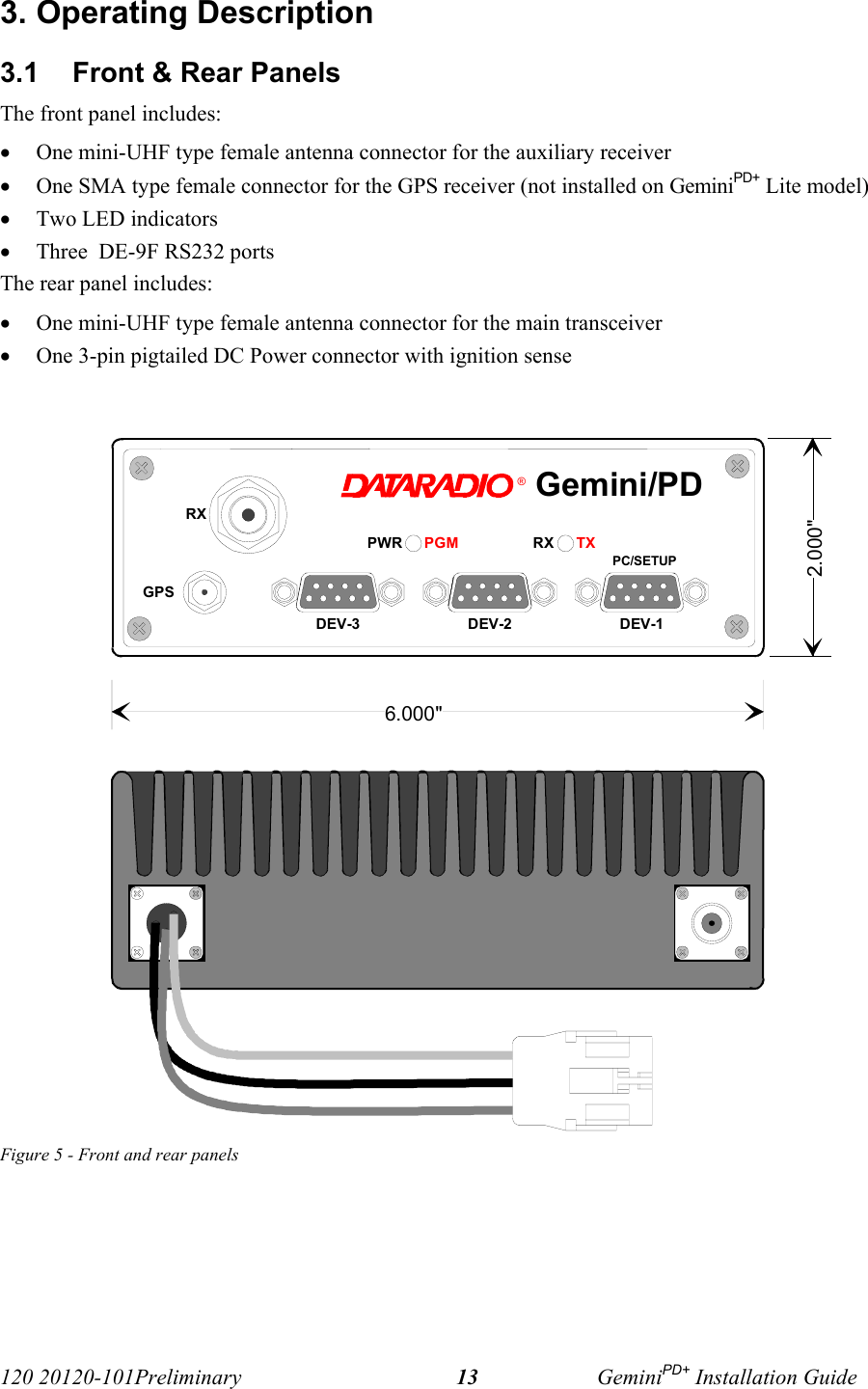
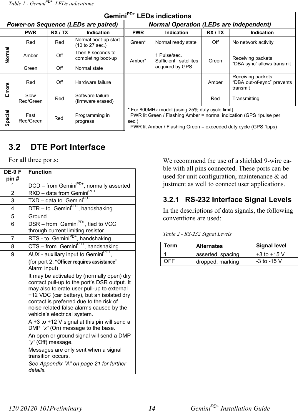
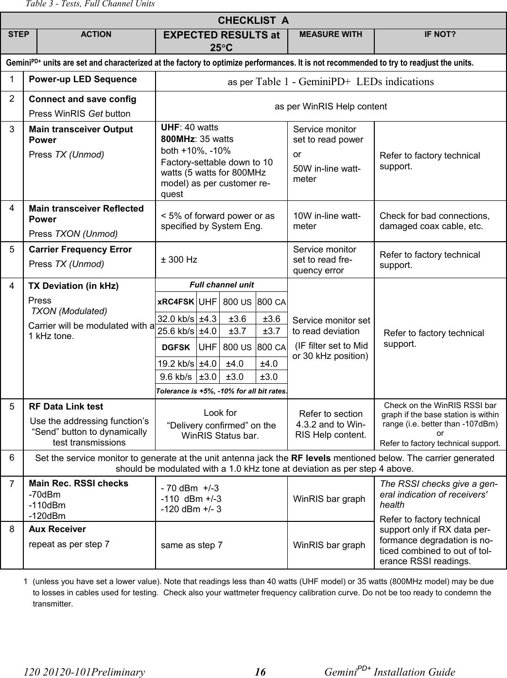
installation manual
Contents
1.
installation manual
2.
updated preliminary manual following MPE test
3.
preliminary version including cable looses as recommended
4.
updated preliminary user manual
5.
preliminary user manual rev 005
installation manual
Navigation menu
Upload a User Manual
Namespaces
Wiki Guide
HTML
PDF
Info
Views
User Manual
Discussion / Help
Navigation