CARRIER Furnace/Heater, Gas Manual L0503144
User Manual: CARRIER CARRIER Furnace/Heater, Gas Manual CARRIER Furnace/Heater, Gas Owner's Manual, CARRIER Furnace/Heater, Gas installation guides
Open the PDF directly: View PDF ![]() .
.
Page Count: 48
88MSA
4-Way MuMtipoise Fixed-Capacity
Condensing Gas Furnace
\isit _ v_w carrier.corn
Installation, Start-Up, and Operating
For Sizes 040--120 Series t50
HEATUNG & COOUNG
I mlCI[NCY
A93040
NOTE: Read the entire instl_action manual be%re starting the
installation
This symbol -->indicates a change since the last issue,
Index Page
DIMENSIONAL DRAWING 3
SAFETY CONSIDERATIONS 2
(learances to ( ombustibles 4
CODES AND STANDARDS ........................................................ 5
ELE< TROSTATIC DIS<HARGE (ESD) PRE(AUTIONS ........ 5
INTRODU< TION .......................................................................... 5
APPLICATIONS ..................................... 6
General ........................................... 6
[pflow Applications ............................... 6
Downflow Applications ............................. 8
Horizontal Lek (Supply-Air Dischmge) Applications ....... 9
Horizontal Right {Supply-Air Discharge) Applications ..... 11
LO< ATION ........................................ 13
Gene*al .......................................... 13
Furnace Location Relative to ( ooling Equipment ......... I4
Hazardous Locations .............................. 14
AIR FOR COMBUSTION AND VENTILATION .......... 14
INSTALLATION ........................................ 18
Leveling Legs (If"Desired) .............................. 18
Installation in Upflow and Downflow Applications ......... 18
Installation In Horizontal Applications .................. 18
Air Ducts ....................................... ! 8
General ........................................ 18
Ductwork Acoustical Treatment .................... 20
Supply Air Connections ......................... 20
Return Air Connections .......................... 20
Filter Arrangement ................................ 20
Bottom Closure Panel ............................ 21
Gas Piping ....................................... 22
Electrical ( onnections ............................. 23
115-v Wiring ................................... 23
24-v Wiring .................................... 24
Accessories .................................. 24
Venting ............................................ 27
Removal of Existing Furnaces from
( ommon Vent Systems .......................... 27
Combustion-Air and Vent Piping ................... 28
Vent Te*mination .............................. 35
Multiventing ................................. 35
As an FNFR(JY ST4Rx¢
Pa_ner Carrier Corpora-
tion has determined that
this pro_tct meets the EN'-
FRGY S fARaV g/iidelines
_r energy efflc{ency
I$O 9001:2000
@
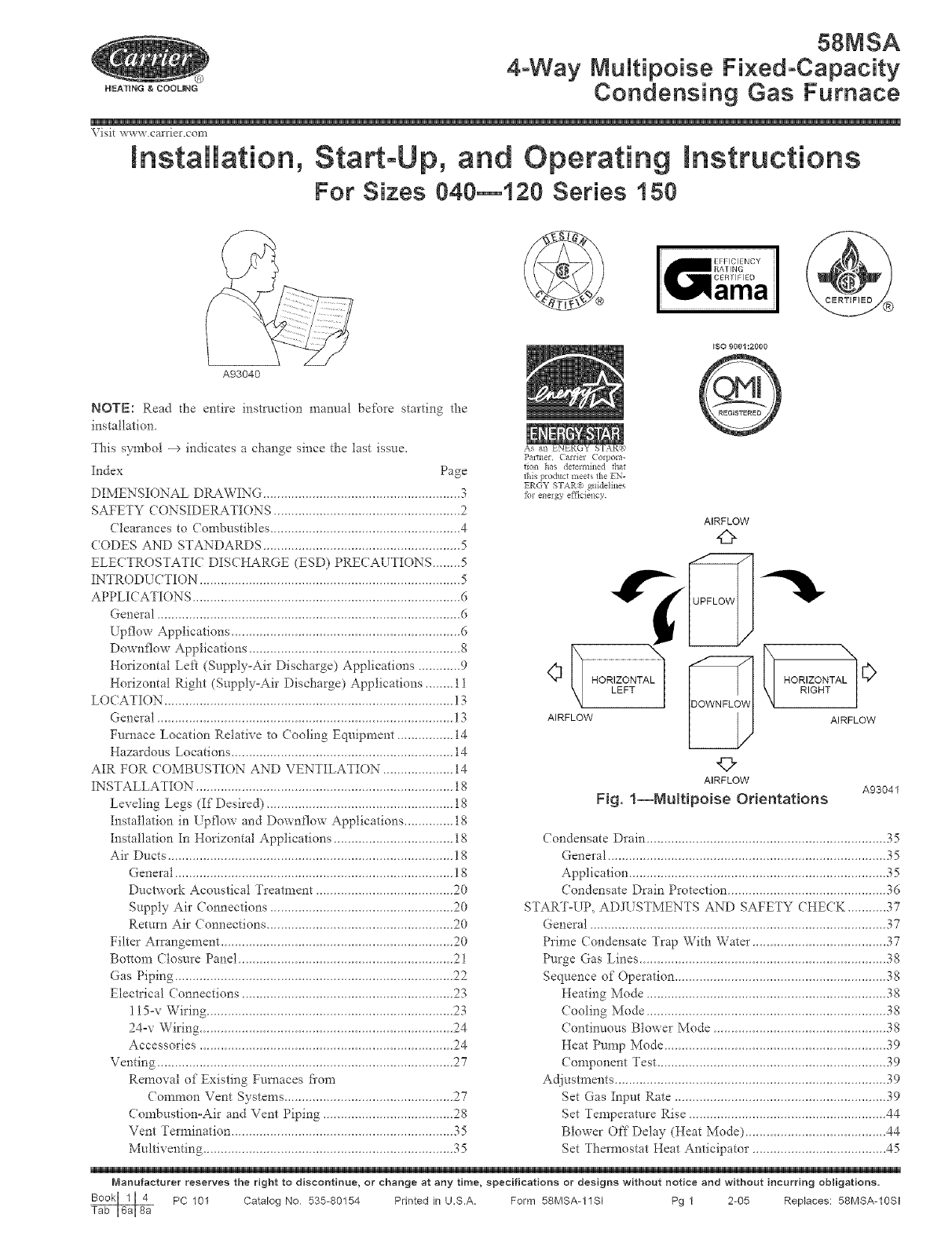
AIRFLOW
42>
r
¢ _ HORLIZOTNTA _ _ _ HO _II_C_NTALN'NI 0
AIRFLOW AIRFLOW
©
AIRFLOW A93041
Fig. 1--NuRipoise Orientations
Condensate Drain .................................................................... 35
General ....................................... 35
Application ....................................... 35
Condensate Drain Protection ...................... 36
START°UP, ADJL STMENTS AND SAFETY (HECK ....... 37
General .......................................... 37
Prime ( ondensate Trap With Warm .................... 37
Purge Gas Lines ................................... 38
Sequence of Operation ............................. 38
Heating Mode ................................. 38
Cooling Mode ................................ 38
Continuous Blowe* Mode ........................ 38
Heat Pump Mode .............................. 39
Component Test ............................... 39
Adjustments....................................... 39
Set Gas Input Rate .............................. 39
Set Temperature Rise ................................ 44
Blower Off"Delay (Heat Mode) .................... 44
Set Thermostat Heat Anticipator .................... 45
Manufacturer reserves the right to discontinue, or change at any time, specifications or designs without notice and without incurring obligations.
PC 101 Catalog No 535-80154 Printed in U.S.A. Form 58MSA-11SI Pg 1 2-05 Replaces: 58MSA-10SI
Check Safhty Controls 45
Check Prima_ Limit Control 45
Check Pressure Switch 45
CHECKLIST ...................................... 45
SAFETY CONSIDERATIONS
FURNACE RELIABILITY HAZARD
Improper installation or misapplication of fml_ace may re=
quire excessive servicing o1" cause premature component
failm'e
Application of this fm'nace should be indoors with special
attention given to vent sizing and material, gas input rate, air
temperature rise, unit leveling, and unit sizing.
FIRE, EXPLOSION, ELECTRICAL SHOCK AND
CARBON MONOXIDE POISONING HAZARD
Failure to follow this warning could result in electrical shock,
firQ personal ir!inry, or death,
Improper installation, adjustment, alteration, service, mainte°
nance, or use can cause carbon monoxide poisoning, explo=
sion, fire, electrical shock, or other conditions which may
cause personal Jr!ire'y.,-or property damage. Consult a qualified
installer, smwice agency, local gas supplier, or your distribu-
tor or branch fbr information or assistance. The qualified
installer or agency must use only [itctory=authorized and
listed kits or accessories when modi_)ing this product.
Installing and servicing heating equipment can be hazardous due to
gas and electrical components. Only trained and qualified
persomiel should instMl, repair, or service heating equipment.
Untrained personnel can perform basic maintenance fimctions
such as cleaning and replacing air filters All other operations must
be performed by trained service personnel. When working on
heating equipment, observe precautions in literature, on tags, and
on labels attached to or shipped with unit and other safety
precautions that may apply
These instructions cover the minimum requirements and confoml
to existing national standards and safkty codes In some instances,
these instructions exceed certain local codes and ordinances,
especially those that may not have kept up with changing resider>
tial construction practices. We require these instrnctions as a
minimum ibr a saf_ installation
Wear safety glasses and work gloves. Have a fire extinguisher
available during start=up and adjustment procedures and service
calls,
CUT HAZARD
Failure to %tlow this caution may result in personal injury.
Sheet metal parts may have sharp edges or bun's Use care and
wear appropriate protective clothing and gloves when ban=
dling parts.
Recognize safety information. This is the safety=alert symbol Z_
When you see this symbol on the unit and in instructions or
manuals, be alert to the potential for personal injury.
--€
--€
--€
--€
--€
-->
Understand these signal words DANGER, WARNING, and (AU°
TION These words are used with the safkty=alert symbol. DAN-
GER identifies the most serious hazards which will result in severe
personal injury or death. WARNING signifies hazards which
could result in personal injury or death. CAUTION is used to
identify unsafe practices which ma? result in minor personal
injury or product and property damage NOTE is used to highlight
suggestions which will result in enhanced installation, reliability,
or operation.
The 58MSA Muhipoise Condensing Gas-Fired Furnaces are CSA
(fbm_erly AGA and (GA) design-certified for natural and propane
gases (see ftmmce rating plate) and fbr installation in alcoves,
attics, basements, closets, utility rooms, erawlspaces, and garages.
The fi/rnace is factory=shipped fbr use with natural gas. A CSA
listed gas conversion kit is required to convert furnace for use with
propane gas.
See Fig. 3 for required clearances to combustibles.
Maintain a l-in. clearance fiom combustible materials to supply air
ductwork for a distance of 36 inches horizontally fiom the fimaace.
See NFPA 90B or local code fbr further requirements.
These furnaces SHALL NOT be installed directly on carpeting,
tile, or any other combustible material other than wood flooring. In
downflow installations, factory accessow floor base MUST be
used when installed on combustible materials and wood flooring.
Special base is not required when this Nmace is installed on
manufacturer's (:oil Assembly Part No. CD5 or CK5, or when Coil
Box Part No. KCAKC is used. The design of this fi/rnace line is
NOT CSA (formerly AGA and CGA) designocertified fbr instal-
lation in recreation vehicles, manufi_ctured mobile homes, or
outdoors.
This furnace is designed for continuous return-air mininmm
temperature of 60_>F db or intermittent operation down to 55°F db
such as when used with a night setback thermometer. Return-air
temperature must not exceed 80°F db. Failure to follow these
return-air limits may affect reliability of heat exchangers, motors,
and controls. (See Fig. 4.)
These Nrnaces are shipped with the drain and pressure robes
connected for UPFLOW applications. Minor modifications are
required when used in DOWNFLOW, HORIZONTAL RIGHT, or
HORIZONTAL LEFT (supply=air discharge direction) applica-
tions as shown in Fig. 1. See details in Applications section.
Install this Nmace only in a location and position as specified in
LOCATION and INSTALLATION sections of these instnlctions.
Combustion products must be discharged outdoors. Connect this
furnace to an approved vent system only, as specified in the
Combustion Air and Vent piping sections of d_ese instructions.
Never test for gas leaks with an open flame. Use a commercially
available soap solution made specifically for detection of leaks to
check all connections as specified in the GAS PIPING section of
these instructions.
Always install the furnace to operate within the fitrnace's intended
rise range with a duct system which has an external static pressure
within the allowable range as specified in the SET TEMPERA-
TURE RISE section of these instructions.
When a Nrnace is installed so that supply ducts carry air circulated
by tl_e fi/rnace to areas outside the space containing the f:umace,
the return air shall also be handled by ducts sealed to the Nrnace
casing and terminating outside the space containing the fhrnace.

22 _"_
T
I4 _" SIDE INLET
TYP
S{OEiNLET
26 _,e"TVp
HORIZONTAL LEFT)
POWER CONN
ACCESSORY [ J
POWERENTRY 2]
_ CONDENSATE
DRAINTRAP
LODATION
(ALTERNATE
UPFLOW) 24
17 :,i_"
9/6" !
TiP
CONDENSATE
DRAIN LO CATION
(UPFLOW)
P
©
A_RFLOW
OaT TYP
t
{DOWNFLOW&
HORIZONTALRIGHT)
ORALTERNATE
gqN DIAGAS CONN
1
30 _;"
DRA_N LOCATION
(UPFLO\M)
DIMPLE LOCATORS
FOR HORIZONTAL
HANGING
i
i
i
i
i
qN DIA
THERMOSTAT ENTRY
2qN VENT CONN
SIDE iNLET
BOTTOM iNLET
UNIT SIZE
040-08
040-t2
080-08
080-t2
080-t6
080-t2
080-t6
080_20
100-16
100-20
120_20
NOTES: 1. Minimum return-air openings at furnace, based on metal duct if flex duct is used,
see flex duct manufacturer's recommendations for equivalent diameters
2 Minimum return-air opening at furnace:
a, For 800 CFM-16-in, round or 14/_ x 12-in rectangle
b For 1200 CFM-20qn, round or 14'h x 19 Lqn, rectangle
c, For 1600 CFM-22qn, round or 14/;, x 23 L-in, rectangle
d For airflow requirements above 1800 CFM see Air Delivery table in Product Data
literature for specific use of single side inlets The use of both side inlets a
combination of 1 side and the bottom, or the bottom only will ensure adequate
return air openings for airflow requirements above 1800 CFM at 0_5 WC ESP
A
17-I/2
17-I/2
17-I/2
17-I/2
17-I/2
17-I/2
17-I/2
21
21
21
24-I/2
Dimensions (In.)
D
15-7/8
15-7/8
15-7/8
15-7/8
15-7/8
15-7/8
15-7/8
19-3/8
19-3/8
19-3/8
22-7/8
E
16
16
16
16
16
16
16
19-1/2
19-1/2
19-1/2
23
A02149
Fig. 2--Dimensional Drawing

--->A gas-fired fire, ace %1"installation in a residential garage must be
installed as specified in the Hazardous Locations section of these
insm/etions,
--> The [:urnaee is not to be used %r tempora Uheating of buildings or
structures under construction unless the furnace installation and
operation complies with the first CAUTION in the LOCATION
section of these instructions,
These fi.u'naces are shipped with the %llowing materials to assist in
proper furnace installation, These materials are shipped in the main
blower compartment,
Installer Packet includes:
Installation, Startup, and Operating instructions
Service and Maintenance instructions
User's Information Manual
Warranty Certificate
Loose Parts Bag includes: Quantity
Pressure tube extension 1
Collector Box or condensate trap extension tube 1
Inducer housing drain tube 1
1/2-in CPVC street elbow 2
Drain tube coupling 1
Drain tube coupiing grommet 1
Vent and combustion-air pipe support 2
Condensate trap hole filler plug 3
Vent and combustion-air intake hole filler ptug 2
Combustion-air pipe perforated disk assembly 1
Vent Pipe Extension 1"
* ONLY supplied with some furnaces.
e This forced air lurnace is equipped for use with natural gas at altitudes 0 -10.000 ff (0 -3,050m), except 140 size _rnaces are only approved for altitudes 0 -7.000 ft.
(0 -2,135m).
¢ An accessory kit, supptied by tbe manufacturer, shall be used to convert to propene gas use or rr_ay be required for some natural gas apptications.
o This furnace is for indoor installation in a building constructed on site. This furnace may be ins"tailed in a manufactiJred (mobile) home when stated on rating plate and
using factory authorked kit..
This furnace may be tilstalled on combustible floodng in alcove or closet at Minimum Inches Clearance To Combustible Construction as described below.
® This furnace requires a special venting system Refer to the installation instructions for parts list and method of installation. This furnace is for use with schedule-40 PVC.
PVC-DW%L CPVC. or ABS-DWV pipe, and must not be vented in common with other gas-tired apptiances. Construction tbrough which vent/air intake pipes may be
installed is maximum 24 inches (600 ram), minimum 3/4 inches (19 ram) thickness (including roofing materials)
e Cetta fournalse &air puls6 est 6quip6e peur utitisation avec gaz naturel et altitudes compdees entre 0 - 3.050m (0 - 10,000 pi),except6 queles fournaises de 140 taille
sont pour altitudes comprises entre 0 - 2,135m 0 - 7,000pi).
® Ut set une trousse de cenvers on. fourn e par e fabr can, pour passer au gaz propane ou pour certaines installations au gaz natureL
o Cetta fournaise a air puls6 es"t pour installation a Fint6rieur darts un bNiment construit sur place. Cetta fournalse a air pulse peut 6tre install6e dens une maison
pr6fabdqu6e (maison mobile) si prescht par la plaque signN6tique et si r on utitise une trousse specifi6e par le labdcant.
e C'etta fournaise peut _tre instati6e sur un plancher combustible darts un enfoncement ou un placard en observant les D_gagement Minimum En Pouces Ave¢
Elements De Construction Combustibles,
® Cetta fournaise n6cessite un systeme d'evaoJation special La m6thede d'installation et la tiste des pieces n6cessaires figurent dens les instructions d'instatiation. Cetle
fournalse doit s'u!itiser avec la tuyautede des nomendatures 40 PVC. PVC-DWV, CPVC, oN ABS-DVW et elle ne peut pas 6tre ventil6e conjointment avec d'autres
appereils a gaz. Epalsseur de la construction au travers de laquetie il est pcesible de laire passer les tuyaux d'a6ration (admlssion/6vacuation): 24 po ('600 ram)
maximum. 3/4 po (19ram) minimum (y cornprls la toiture)
For uptiow and downtiow applications, furnace mu_t be installed level, or pitched within 1/2" of level For a M IN 1/4" TO 1/2" MAX
horizontal apptication, the furnace must be pitched minimum 1/4" to maximum of 1/2" forward for proper
draina:je. See Installation Manual for IMPORTANT unit supped details on horizontal apptications,
Pour des appticatises de flux ascendent et descendant. _ fournaise ddt 8tre install6e de niveau ou indti%,e
pes plus de 1/2" du niveau. Pour une apptication hodzontale, la fournalse doit g,tre inciinde entre minimum
1/4" et maximum 1/2" du nNeau pour le drainage appropd6. En _ d'instatiation en position beCEontale.
consulter les renseignements tMPORTANTS sur le support dens le manuel d'instatiation. HORIZON TAL
NtNINUN iNCHES CLEARANCE TO CONBUSTtBLE CONSTRUCTION
ALL POSITIONS:
Minimum front clearance for service 24 inches (610mm),
? ? 140 size furnaces require 1 inch back clearance to combustible materials,
DOWNFLOW POSITIONS:
t For ir_stallation on cembustible floors only when installed on special base No, KGASB0201ALL,
Coil Assembly Part No, CD5 or CKS, or Coil Casing, Part No, KCAKC,
HORIZONTAL POSITIONS:
Line contact is permissible only between lines formed by intersections of top and two sides of
furnace jacket, and building joists, studs, or framing,
§ Clearance shown is for air inlet and air outlet ends.
O 120 and 140 size furnaces require 1 inch bottom clearance to combustible materials,
DEGAGEMENT MINIMUM EN POUCESAVEC _LEMENTS DE CONSTRUCTIONCOMBUSTIBLES
POUR TOUS LES POSITIONS:
Degagen_ent avant minimum de 610mm (24 po ) pour l'entretien,
tt Pourlesfoumaissede 140taille,1 po (25mm)degagen-entdesn_t@iauxcombustiblseest
requis au-arriere.
POUR LA POSITION COURANT DESCENDANT:
1 Pour Iinstallation sur le plancher combustible seulement quand on utilise la base speciale, piece
n ° KGASB0201ALL, I'sesemble serpentin, piece n° CD5 ou CKS, ou le carter de serpentin,
piece n° KCAKC.
POUR LA POSITION HORIZONTALE:
Le contact n'est pem?is qdentre les ligses forages par les intersections du dessus et des
deuxoStes de la chemise de la foumaise et des selives, des n_ntan% ou de la charpente du
b4,timent,
§ La distance indiquee cenceme I'extr@mit6 du tuyau d'arrivde d'air et Fextremite du tuyau de sortie
d'air,
Pour Ise foumaises de 120 et 140 taille 1 po (25ram) d&Jagement des mat@iaux combusitbles
est requis au<l_'ssous.
TNs furnace is approved for UPFLOW, DOWNFLOW aed
HORIZONTAL instNlations,
Cette toumaise est approuv¢e pour Iinstallaflon HORIZONTALE
e! la circulaJion d'air VERS LE HAUT et VERS LE BAS
Cleat_nce arrows
do not change with ne change pas avec
furnace onentation I'odentation de la
gen@aIeur d'air cbaud.
Vent clearance to
combustibles 0",
Clearance in inches 0 (po) Ocgagement
Degagetnent (po), d'@vent avec combustibles
3280_201 REV, B LITTOP
Fig. 3--Clearances to Combustibles
4
J
A04110

"} MAX 80°F
FRONT
RETURN
AHR MHN60°F
A05004
--9 Fig. 4_Retum-Air Temperature
For accessory installation details, refer to accesse D' installation
instructions
--@ ,
CODES AND STANDARDS
Follow all national and local codes and standards in addition to
these instructions° The installation must comply with regulations
of the serving gas supplier, local building, heating, plumbing, and
other codes. In absence of local codes, the installation must
comply with the national codes listed below and all authorities
having jurisdiction.
In the United States and Canada, follow all codes and standards for
the _bllowing:
Step l--Safety
* US: National Fuel Gas (ode (NFGC) NFPA 54-2002/ANSI
Z223.1 °2002 arid the Installation Standards, Warm Air Heating
and Air (onditioning Systems ANSI NFPA 90B
* CANADA: National Standard of Canada, Natnral Gas and
Propane Installation Code (NS(NGPIC) CSA BI49J-00.
Step 2--General Installation
*US: NFG( and the NFPA 90B. For copies, contact the National
Fire Protection Association Inc, BatteD-march Pad< Quincy,
MA 02269; or for only the NFG( contact the American Gas
Association, 400 N. Capitol, N.W., Washington DC 20001
A manu_hctured (Mobile) home installation must con_brrn with
the Mam!/actured h2)me d'onstl'z¢ctior_ as_d &{fi.-t3' Sta,c/ard
Tide 24 (iFR, Part 3230, or when this standard is not
applicable, the Standard _br _l,Ian@tctz¢red Hnme l_Tst_d]ation
(.hIclmt/act_lred D))me Sites, ('omm_¢nitie.s, and Set-L_.s),
AXIST/A'C_' A225. l, an&or (14A',( %-l-Z240, liD" Serie.s 3/obiIe
Hom_,s'
* CANADA: NSCNGPI& For a copy, contact Standard Sales,
CSA International, 178 Rexdale Boulevard, Etobicoke
(Toronto), Ontario, M9W IR3, Canada.
Step a--Combustion and Ventilation Air
* US: Section 8.3 of the NFGC, Air for (ombnstion arid
Ventilation
* CANADA: Part 7 of d-ie NSCNGPIC, Venting Systems and Air
Supply _k}r Appliances
Step 4--Duct Systems
* US and (ANADA: Air (onditioning (ontractors Association
(AC(A) Manual D, Sheet Metal and Air Conditioning (7on-
tlactors National Association (SMACNA), or American Soci-
ety of Heating, Refrigeration, and Air Conditioning Engineers
(ASHRAE) 2001 Fundamentals Handbook Chapter 34.
Step 5--Acoustical Lining and Fibrous Glass Duct
* US and (ANADA: current edition of SMACNA, NFPA 90B as
tested by UL Standard 181 for (;lass I Rigid Air Ducts
Step g--Gas Piping and Gas Pipe Pressure Testing
*US: NFG( chapters 2, 3, 4_ and 9 and national phn'nbing codes
In the state of Massachusetts:
This product must be installed by a licensed plumber or gas
fitter.
When flexible connectors are used, the maxinmm length shall
not exceed 36 inches.
When lever type gas shutof_is are used they shall not exceed 36
inches.
CANADA: NSCNGPIC Parts 3, 4, 5, A, B, E, and H.
Step 7--Emectrical Connections
* US: National Electrical (ode (NE() ANSIiNFPA 70°2002
CANADA: (anadian Electrical (ode CSA C22.1
ELECTROSTATIC DISCHARGE {ESD) PRECAUTIONS
[NIT DAMAGE HAZARD
Faihn'e to follow this caution may result in damage to unit
components.
Electrostatic discharge can affect electronic components.
Take precautions during furnace installation and servicing to
protect d_e t:umace electronic control. Precautions will pre-
vent electrostatic discharges fiom personnel and hand tools
which are held during the proce&re. These precautions will
help to avoid exposing the control to electrostatic discharge
by putting d_e [:urnace, the control, and the person at the same
electrostatic potential.
1. Disconnect all power to the furnace. Multiple disconnects may
be required. DO NOT TOU(H THE CONTROL OR ANY
WIRE CONNE(TED TO THE ( ONTROL PRIOR TO DIS-
(HARGING YOUR BODY'S ELECTROSTATI( CHARGE
TO GROUND.
2 Firefly touch a clean, unpainted, metal surface of the fmTlace
chassis which is close to the control. Tools held in a person's
hand during grounding will be satisfactorily discharged.
3. After touching the chassis you may proceed to service the
control or connecting wires as tong as you do nothing that
recharges your body with static electricity (fbr example; DO
NOT move or shuffle your feet, DO NOT touch ungrounded
objects, etc)
4 If you touch ungronnded objects (recharge your bo@ with
static electricity), firmly touch the unpainted metal surfi_ce of
the furnace again be_bre touching control or wires.
5. Use this procedure for installed and urdnstalled (ungrounded)
_i/rnaces
6. Befbre removing a new control fiom its container, discharge
your body's electrostatic charge to ground to protect dae
control from damage. If d_e control is to be installed in a
ii/mace, _bllow items 1 through 5 be_bre bringing the control
or yourself into contact with the furnace. Put all used and new
controls into containers be_bre touching ungrounded objects.
7. An ESD service kit (available ti'om commercial sources) may
also be used to prevent ESD damage.
INTRODUCTION
The model 58MSA 4-way multipoise, Gas-Fired, Category IV,
condensing furnaces are available in model sizes ranging in gas
input rates of 40,000 to 120,000 Bmh.

__D FURNACE
OOR
TRAP (INSIDE_ X[
TU% OOSO ETRAP
DRAIN TUBE LOCATION
UPFLOW APPLICATIONS
FIELD--
DRAIN
CONN
/-- CONDENSATE
/TRA uRNAOE7
JS'DV
Y,--? /o
£_2% ......
26_/4 1_/2
SIDE VIEW FRONT VIEW
DOWNFLOW AND ALTERNATE
EXTERNAL UPFLOW APPLICATIONS
_1 FURNACE
OOR
FIELD --
DRAIN
CONN
-- FURNACE
SIDE
¾
END VIEW FRONT VIEW
HORIZONTAL
APPLICATIONS
s'-°7'-%:°:U7
(OPTIONAL) /
Z W, ET,E
GUIDES
(WHEN USED)
71/8
l
COD
COLLECTOR BOX TO
TRAP RELIEF PORT
_OD
INDUCER HOUSING
DRAIN CONNECTION
'_OD
COLLECTOR BOX
DRAIN CONNECTION
SCREW HOLE FOR
UPFLOW OR DOWN-
FLOW APPLICATIONS
(OPTIONAL)
YnlN. PVC OR CPVC
FRONT VIEW SIDE VIEW
A93026
Fig. 8--Condensate Trap
MINOR PROPERTY DAMAGE
Failure to follow this caution may result in minor property
damage,
Local codes may reqnire a drain pan under entire _rnace and
condensate trap when a condensing furnace is used in an attic
application or over a finished ceiling.
APPLiCATiONS
Step l--General
Some assembly and modifications are required for fire, aces
installed in any of the 4 applications shown in Fig. 1. All &ain and
pressure robes are connected as shown in Fig 6 See appropriate
application instructions _br these procedures
Step 2--Upflow Applications
An upflow t'tmlace application is where fm'nace blower is located
below combustion and controls section of ffimace, and conditioned
air is discharged upwards
( ONDENSATE TRAP LO(ATION (FACTORY-SHIPPED
ORIENTATK)N)
The condensate tlap is _hctory installed in the blower shell:"and
fhctory connected for UPFLOW applications. A factory-supplied
tube is used to extend the condensate trap drain connection to the
desired furnace side %r field drain attachment See Condensate
Trap Tubing (FactoQ--Shipped Orientation) section *%r drain tube
extension details. (See Fig. 6.)
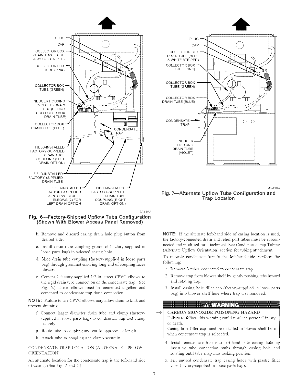
CONDENSATE TRAP TL BING (FACTORY-SHIPPED
ORIENTATION)
NOTE: See Fig. 6 or robe routing label on main furnace door to
confirm tocation of these tubes
l. ( ollector Box Drain, Inducer Housing Drain, Retief Port, and
Pressure Switch Tubes
These tubes are fhcto W attached to the condensate trap and
pressure switch ready _;oruse in UPFLOW applications. These
robes can be identified by their connection location and also
by a color label on each robe. These robes are identified as
£_llows: collector box &ain robe (blue label), inducer housing
&ain robe (violet label or molded), relief port robe (green
label), and pressure switch robe (pink label).
2. (ondensate Trap Drain Tube
The condensate trap drain connection must be extended for
field attachment by doing the *%llowing:
a. Detemine location of field drain connection. (See Fig. 2or
6.)
NOTE: If internal filter is used, drain robe should be located to
opposite side of casing from remm duct attachment to assist in
filter removal.
PLUG
CAP
COLLECTOR
DRAIN TUBE (BLUE
& WHITE STRIPED)
COLLECTOR
TUBE (PINK)
COLLECTOR BOX --_
TUBE (GREEN)
(MOLDED) DRAIN
TUBE (BEHIND
COLLECTOR BOX
DRAIN TUBE)
DRAIN TUBE (BLUE)
FACTORY-SUPPLIED
DRAIN TUBE
COUPLING (LEFT
DRAIN OPTION)
FIELD-INSTALLED
FACTORY-SUPPLiED
DRAIN TUBE
FIELD-INSTALLED
FACTORY-SUPPLIED
V_-IN. CPVC STREET
ELBOWS (2) FOR
LEFT DRAIN OPTION
FIELD-INSTALLED
FACTORY-SUPPLIED
DRAIN TUBE
COUPLING (RIGHT
DRAIN OPTION)
A94163
Fig. 6--Factory-SNpped Upflow Tube Configuration
(Shown With Blower Access Panel Removed}
b. Remove and discard casing drain hole plug button from
desired side.
c Install &ain tube coupling grommet (factor-supplied in
loose parts bag) in selected casing hole.
& Slide drain robe coupling di_ctok_'°supplied in loose parts
bag) through grommet ensuring tong end of coupling fi_ces
blower.
e. Cement 2 factory°supplied 1i2qn. stleet CPVC elbows to
the rigid drain tube connection on the condensate trap. (See
Fig. 6.) These elbows must be cemented together and
cemented to condensate trap drain connection.
NOTE: Failure to use CPV( elbows may allow &ain to kink and
prevent draining.
t_ Connect larger diameter drain tube and clamp (factory°
supplied in loose parts bag) to condensate trap and clamp
securely.
g. Route robe to coupling and cut to appropriate length.
h. Attach robe to coupling and clamp securely.
(ONDENSATE TRAP LOCATION (ALTERNATE UPFLOW
ORIENTATION)
An alternate location fbr the condensate tlap is the left-hand side
of casing. (See Fig 2and 7)
PLUG
CAP
COLLECTOR BOX
DRAIN TUBE (BLUE
& WHITE STRIPED)
COLLECTOR BOX
TUBE (PINK)
COLLECTOR BOX
TUBE (GREEN)
COLLECTOR BOX
DRAIN TUBE (BLUE)
TRAP
HOUSING
DRAIN TUBE
(VIOLET)
O O
A94164
Fig. 7--Alternate Upflow Tube Configuration and
Trap Location
--9
NOTE: If the alternate tef_-hand side of casing location is used_
the factory-connected drain and relief port robes must he discon-
nected and modified for attachment See Condensate Trap Tubing
(Alternate Upflow Orientation) section for tubing attachment
To relocate condensate trap to the te_t-hand side, perfbrm the
following:
1 Remove 3 tubes connected to condensate t_ap.
2 Remove trap from blower shelf by gently pushing tabs inward
and rotating trap.
3. Install casing hole filler cap (_i_ctory=supplied in loose parts
bag) into blower shelf hole where trap was removed.
CARBON MONOXIDE POISONING HAZARD
Failure to follow this warning eoutd result in personal inju W
or death,
Casing hole filler cap must be installed in blower shelf hole
when condensate trap is relocated.
4 Install condensate trap into left=hand side casing hole by
inserting tube cormection stubs through casing hole and
rotating until tabs snap into locking position.
5. Fill unused condensate tlap casing holes with plastic filler
caps (bactory=supplied in loose parts bag).

CONDENSATETRAPTUBING(ALTERNATEt PFL()W
ORIENTATION)
NOTE:SeeFig.7orroberoutinglabelonmainfhrnacedoorto
confirmlocationoftheserobes
1.(ollectorBoxDrainTube
(onnectcollectorboxdrainrobe(bluelabel)tocondensate
t_ap.
NOTE:On17-1/2-in.widetk_rnacesONLY,cuttubebetween
corrugatedsectionstopreventkinksfloraoccurring.
2. InducerHousingDrainTube
a.RemoveanddiscardLOWER(molded)inducerhousing
&Bintubewhichwaspreviouslyconnectedtocondensate
t_ap.
b. [seinducerhousing&Binextensiontube(violetlabeland
fhctow-suppliedinloosepartsbag)toconnectLOWER
inducerhousing&Binconnectiontothecondensatetrap
c.Determineappropriatelength,cut,andconnectrobe
d.Clamprobetopreventanycondensateleakage.
3.ReliefPortTube
a.(onnectreliefporttube(greenlabel)tocondensatetrap.
b. Usesmallerdiametertube(fitctory=suppliedinlooseparts
bag)toextendthistubeif required.
c.Determineappropriatelength,cut,andconnectrobe.
( ONDENSATETRAPFIELDDRAINATTACHMENT
Referto CondensateDrainsectionfor recommendationsand
procedures.
PRESStRESWIT(HTt BING
TheLOWER collector box pressure tube (pink 1abel) is facto W
connected to the pressure switch and should not require any
modificatiom
COLLECTOR
DRAIN TUBE (BLUE)
TUBE (GREEN)
EXTENSION TUBE
TUBE (PINK)
COLLECTOR
DRAIN TUBE (BLUE
& WHITE STRIPED)
EXTENSION TUBE
TRAP ©
INDUCER HOUSING
DRAIN TUBE(VIOLET)
Fig. 8--Downflow Tube Configuration
(Left-Hand Trap Installation)
A94165
NOTE: See Fig 6 or 7 or robe routing label on main furnace door
to check fbr proper connections.
UPPER COLLECTOR BOX AND INDUCER HOUSIN'G
(UNUSED) DRAIN" CONNE(TIONS
tipper (ollector Box Drain Connection
Attached to the tIPPER collector box drain connection is a
factory-installed corrugated, plugged tube (blue and white striped
label). This tube is plugged to prevent condensate leakage in this
application. Ensure this robe is plugged.
NOTE: See Fig. 6 or 7 or tube routing label on main furnace door
to check fbr proper connections.
tipper Inducer Housing Drain (onnection
Attached to the tIPPER (unused) inducer housing &Bin connection
is a cap and clamp. This cap is used to prevent condensate leakage
in this application Ensure this connection is capped.
NOTE: See Fig. 6 or 7 or tube routing label on main fhrnace door
to check fbr proper connections.
CONDENSATE TRAP FREEZE PROTECTION
RefBr to (ondensate Drain Protection section for recommenda-
tions and procedures.
Step 3--Oownflow Applications
A downflow ftn'nace application is where fitmace blower is located
above combustion and controls section of furnace, and conditioned
air is discharged downwards.
CONDENSATE TRAP LOCATION
The condensate trap must be removed from the fhctow-installed
blowe* shelf'location and relocated in selected application location
as shown in Fig 2, 8, or 9.
O O
©
LDRAIN TUBE "_
COUPLING
PLUG
CAP
_ COLLECTOR BOX
DRAIN TUBE (BLUE)
_ COLLECTOR BOX
TUBE (PINK)
COLLECTOR BOX
TUBE (GREEN)
COLLECTOR BOX
EXTENSION TUBE
COLLECTOR BOX
DRAIN TUBE (BLUE
& WHITE STRIPED)
COLLECTOR BOX
EXTENSION TUBE
INDUCER HOUSING
D RAIN TUBE
(VIOLET)
CONDENSATE
TRAP
_'- COLLECTOR BOX
EXTENSION
DRAIN TUBE
Fig. 9--Oownflow Tube Configuration
(Right-Hand Trap Insta{lation)
A94166

-->
To relocate condensate trap fi'om the blower shelf to desired
location, perfbrm the following:
1. Remove 3 tubes connected to condensate t_ap
2. Remove trap from blower shelf by gently pushing tabs inward
and rotating t_ap.
3. Install casing hole filler cap (*hctow-supplied in loose parts
bag) into blower shelf hole where trap was removed.
CARBON MONOXIDE POISONING HAZARD
Failure to fbllow this warning could result in personal in}ury
or death.
Casing hole filler cap must be installed in blower shelf hole
when condensate trap is relocated.
4. Install condensate trap into desired casing hole by inserting
tube connection stubs through casing hole and rotating until
tabs snap into locking position.
5. Fill unused condensate trap casing holes with plastic filler
caps (*i_ctory=supplied in loose parts bag)
CONDENSATE TRAP TUBING
NOTE: See Fig 8 or 9 or robe routing label on main furnace door
to check fbr proper connections.
1. Collector Box Drain Tube
a Remove fimtory=installed plug fi'om LOWER collector box
drain robe (blue and white striped label).
b. Install removed clamp and plug into [PPER collector box
&ain robe (blue label) which was connected to condensate
tlap.
c. Connect LOWER collector box drain connection to con=
densate trap.
(1.) Condensate Trap Located on Left Side of Casing
Ca3 Connect LOWER collector box &ain robe (blue
and white striped label) to condensate tlap. Tube
does not need to be cut.
(b.) Clamp tube to prevent any condensate leakage.
(2.) Condensate Trap Located on Right Side of Casing
Ca3 Install drain robe coupling (fhctow-supplied in
loose parts bag) into collector box drain robe
(blue and white striped label) which was previ=
ously plugged.
(b.) Connect larger diameter &ain robe (_tctory°
supplied in loose parts bag) to &ain tube cou°
piing, extending collector box drain robe for
connection to condensate trap.
(c.) Route extended collector box drain robe between
gas valve and inlet housing as shown in Fig. 9.
(d.) Determine appropriate length and cut.
(e.) Connect to condensate trap.
(f.) Clamp robe to prevent any condensate leakage.
2. Inducer Housing Drain Tube
a Remove fhctoEyoinstalled cap and clamp from LOWER
inducer housing drain connection.
b. Remove and discard UPPER (molded) inducer housing
&ain robe which was previously connected to condensate
t_ap.
c Install cap and clamp on UPPER inducer housing &ain
connection where molded &ain robe was removed.
d. l_se inducer housing &ain robe (violet label and factoQ-
supplied in loose parts bag) to connect LOWER inducer
housing drain connection to the condensate trap.
e. Connect inducer housing drain connection to condensate
trap.
(10 Condensate Trap Located on Left Side of Casing
Ca,) Determine appropriate length and cut,
(b.) Connect tube to condensate trap.
(c.) Clamp robe to prevent any condensate teakage
(20 Condensate Trap Located on Right Side of Casing
Ca.) Route inducer housing drain tube (violet 1abel)
between gas valve and inlet housing behind col-
lector box drain tube
(b) Determine appropriate length and cut
(c.) Connect robe to condensate trap.
(d) Clamp robe to prevent any condensate teakage.
3 Relief Port Tube
Refkr to Pressure Switch Tubing section fbr connection
procedure
CONDENSATE TRAP FIELD DRAIN ATTACHMENT
Refer to Condensate Drain section fbr recommendations and
procedures,
PRESSURE SWITCH TUBING
One collector box pressure tube (pink label) is factory connected to
the pressure switch fbr use when furnace is installed in UPFLOW
applications. This robe MUST be disconnected and used for the
condensate trap relief port robe. The other collector box pressure
robe (green label) which was f_ctory connected to the condensate
trap relief port connection MUST be connected to the pressure
switch in DOVv_TLOW or HORIZONTAL RIGHT applications.
NOTE: See Fig. 8 or 9 or robe routing label on main fhrnace door
to check fbr proper connections
Relocate robes as described below.
1. Disconnect collector box pressure robe (pink label) attached to
pressure switch
2. Use smaller diameter robe (factor-supplied in loose parts
bag) to extend collector box pressure tube (green label) which
was previously connected to condensate t_ap relief port
connection.
3. Connect collector box pressure robe (green label) to pressure
switch connection labeled "collector box."
4. Use remaining smaller diameter robe (factmT-supplied in
loose parts bag) to extend collector box pressure robe (pink
label) which was previously connected to pressure switch.
5. Route this extended tube (pink label) to condensate trap relief
port connection.
6. Determine appropriate length, cut, and connect robe.
7. Clamp robe to relief port connection.
CONDENSATE TRAP FREEZE PROTECTION
Refer to Condensate Drain Protection section for recommenda-
tions and procedures
Step 4--Horizontal Left (Supply-Air Discharge)
Applications
A horizontal left fhrnace application is where fhrnace blower is
located to the right of combustion and controls section of' furnace,
and conditioned air is discharged to the left.

PLUG
AUXILIARY 'U" BOX COLLECTOR BOX
DRAIN TUBE
(BLUE AND WHITE STRIPED)
O
o
CONDENSATE
TRAP COLLECTOR BOX
TUBE (GREEN)
BOX EXTENSION
DRAtNTUBE
COLLECTOR BOX
EXTENSION TUBE
HOUSING
DRAIN TUBE (VIOLET)
BOX
DRAIN TUBE (BLUE)
DRAIN TUBE COUPLING
COLLECTOR BOX TUBE (PINK)
RELOCATE TUBE BETWEEN BLOWER SHELF AND INDUCER HOUSING FOR
040,060, AND 080 HEATING INPUT FURNACES
Fig. 10--Horizontal Left Tube Configuration
A00215
CONDENSATE TRAP LOCATION
The condensate tlap must be removed from the factor-installed
blower shelf location and relocated in selected application location
as shown in Fig. 2or 10.
To relocate condensate trap from the blower shelf to desired
location, perform the Ibllowing:
1. Remove 3 robes connected to condensate trap.
2. Remove tlap flora blower shelf by gently pushing tabs inward
and rotating trap.
3. Install casing hole filler cap (factov-supplied in loose parts
bag) into blower shelf hole where tlap was removed.
-9 CARBON MONOXIDE POISONING HAZARD
Failure to _bllow this warning could result in personal injury
or death.
Casing hole filler cap must be installed in blower shelf hole
when condensate trap is relocated.
4. Install condensate trap into casing hole by inserting tube
connection stubs through casing hole and rotating until tabs
snap into locking position.
5. Fill unused condensate trap casing holes with plastic filler
caps (fi_ctory=supplied in loose parts bag)
CONDENSATE TRAP TUBING
NOTE: See Fig. 10 or tube routing label on main fl/rnace door to
check for proper connections.
10
1. Collector Box Drain Tube
a Install &ain tube coupling (factory-supplied in loose parts
bag) into collector box drain tube (blue label) which was
previously connected to condensate trap
b. Connect large diameter drain robe and clamp (factory-
supplied in loose parts bag) to drain robe coupling, extend-
ing collector box &ain robe
c Route extended robe (blue label) to condensate trap and cut
to appropriate length
d. (lamp robe to prevent any condensate leakage.
2. Inducer Housing Drain Tube
a. Remove and discard LOWER (molded) inducer housing
drain robe which was previously connected to condensate
trap.
b. Use inducer housing &ain extension robe (violet label and
factoryosupplied in loose parts bag) to connect LOWER
inducer housing &ain connection to the condensate trap.
c. Detem_ine appropriate length, cuL and connect robe.
d. (lamp robe to prevent any condensate leakage.
3. Relief Port Tube
a. Use smaller diameter robe (factov-supplied in loose parts
bag) to extend collector box tube (green label) which was
previously connected to the condensate trap.
b. Route extended collector box pressure robe to relief port
connection on the condensate trap.
c. Detem_ine appropriate length, cuL and connect robe.
d. (lamp robe to prevent any condensate leakage.

A 3-IN. MINIMUMCLEARANCE
TO COMBUSTION-AIRINTAKE _VENT
IS REQUIRED.
INTAKE
30-IN. MtN
, A 12-tN. MIN HORIZONTAL PIPE
SECTION tS RECOMMENDED WITH
SHORT (5 TO 8 FT) VENT SYSTEMS
TO REDUCE EXCESSIVE
CONDENSATE DROPLETS FROM
EXITING THE VENT PIPE.
SHUTOFF
GAS VALVE
SEDIMENT
TRAP CONDENSATE
TRAP
DRAIN
ACCESS OPENING
FOR TRAP
NOTE: LOCAL CODES MAY REQUIRE A DRAIN PAN UNDER THE
FURNACE AND CONDENSATE TRAP WHEN A CONDENSING
FURNACE IS INSTALLED ABOVE FINISHED CEILINGS.
Fig. 11--Attic Location and Working Platform
A96184
CONDENSATE TRAP FIELD DRAIN ATTACHMENT
Refer to Condensate Drain section %r recommendations and
procedures
PRESSURE SWIT(H TUBING
The LOWER collector box pressure tube (pink label) is fhctory
connected to the pressure switch for use when [_urnace is installed
in UPFLOW applications. This tube MUST be disconnected,
extended, rerouted, and then reconnected to the pressure switch in
HORIZONTAL LEFT applications.
NOTE: See Fig. 10 or tube routing label on main Nmace door to
check for proper connections.
Modify robe as described below.
1. Disconnect collector box pressure tube (pink label) attached to
pressure switch.
2. Use smaller diameter tube (factory-supplied in loose parts
bag) to extend tube disconnected in item 1.
3. Route extended robe:
a. Behind inducer housing.
b. Between blower shelf and inducer housing.
c. Behind inducer motor bracket.
d. Between inducer motor and pressure switch.
4. Detem_ine appropriate length, cut, and reconnect robe to
pressure switch connection labeled COLLE(TOR BOX.
CONDENSATE TRAP FREEZE PROTECTR)N
Refkr to Condensate Drain Protection section for recommenda°
tions and procedures.
(ONSTRU(T A WORKING PLATFORM
(onstruct working plat%m_ where all required furnace clearances
are met (See Fig. 3 and 11)
INIT MAY NOT OPERATE
Failure to fbltow this caution may result in intem_ittent unit
operation.
The condensate trap MUST be installed below furnace See
Fig. 5 [br dimensions. The drain connection to condensate
nap must also be properly sloped to an open drain.
NOTE: Vent pipe length is restricted to a minimum of 5 It. (See
Table 8.)
NOTE: A 12-in. minimum horizontal pipe section is recom-
mended with short (5 to 8 f_) vent systems. This recommendation
is to reduce excessive condensate droplets fi'om exiting the vent
pipe. (See Fig. 11 or 38.)
Step 5--Horizontal Right (SupplyoAir Discharge)
Applications
A horizontal right furnace application is where furnace blower is
located to the tel} of combustion and controls section of fi/mace,
and conditioned air is discharged to the right.
MINOR PROPERTY DAMAGE
Failure to fbllow this caution may result in minor property
damage
Local codes may require a drain pan under entire furnace and
condensate trap when a condensing fi/rnace is used in attic
application or over a finished ceiling_
11

PLUG
CAP BOX DRAIN TUBE (BLUE)
COLLECTOR BOX TUBE (GREEN)
BOX EXTENSION TUBE
COLLECTOR BOX TUBE (PINK)
BOX RELOCATED HERE
COLLECTOR BOX DRAIN TUBE
(BLUE AND WHITE STRIPED)
INDUCER HOUSING
DRAIN TUBE (VIOLET)
COLLECTOR BOX
EXTENSION TUBE
CONDENSATE
TRAP
A00214
Fig. 12--Horizontal Right Tube Configuration
NOTE: In (anada, installations shall be in accordance with
current NSCNGPIC Installation Codes andor local codes.
NOTE: The auxilial_- junction box (J°Box) MUST be relocated to
opposite side of _/rnace casing. (See Fig. 12.) See Electrical
Connection section _br J-Box relocation.
CONDENSATE TRAP LOCATION
The condensate tlap must be removed from the factor-installed
blower shelf location and relocated in selected application location
as shown in Fig. 2or 12.
To relocate condensate trap from the blower shelf to desired
location, perform the fbllowing:
1. Remove 3 tubes connected to condensate trap.
2. Remove tlap fi'om blower shelf by gently pushing tabs inward
and rotating trap.
3. Install casing hole filler cap (factov-supplied in loose parts
bag) into blower shelf hole where tlap was remo_ ed.
--> (ARBON MONOXIDE POISONING HAZARD
Failure to follow this warning could result in personal in3u D'
or death.
Casing hole filler cap must be installed in blower shelf hole
when condensate trap is relocated.
4. Install condensate trap into casing hole by inserting tube
connection stubs through casing hole and rotating until tabs
snap into locking position.
5. Fill unused condensate trap casing holes with plastic filler
caps (_Sctoryosupplied in loose parts bag)
12
(ONDENSATE TRAP TL BING
NOTE: See Fig 12 or robe routing label on main furnace door to
check for proper connections
1. Collector Box Drain Tube
a Remove _ctoryoinsta!led plug from LOWER collector box
drain robe (blue and white striped label).
b. Install removed clamp and plug into UPPER collector box
&ain tube (blue label) which was previously connected to
condensate tlap.
c. Connect LOWER collector box drain robe (blue and white
striped label) to condensate trap. Tube does not need to be
cut.
d. (lamp robe to prevent any condensate leakage.
2. Inducer Housing Drain Tube
a. Remove fhctoryoinstalled cap and clamp from LOWER
inducer housing drain connection.
b. Remove and discard UPPER (molded) inducer housing
&ain robe which was previously connected to condensate
tlap.
c. Install cap and clamp on UPPER inducer housing &ain
connection where molded &ain robe was removed.
d. Use inducer housing &ain extension tube (violet label and
factory-supplied in loose parts bag) to connect LOWER
inducer housing &ain connection to condensate trap.
e. Detem?ine appropriate length, cuk and connect robe to
condensate trap.
_ Clamp robe to prevent any condensate leakage.
3. Relief Port Tube
Refer to Pressure Switch Tubing section _br connection
procedure.

(ONDENSATETRAP FIELD DRAIN ATTA(HMENT
Ref?r to Condensate Drain section %r recommendations and
procedures
PRESSURE SWITCH TUBING
One collector box pressure tube (pink label) is fhctory connected to
the pressure switch fbr use when furnace is installed in UPFLOW
applications. This robe MUST be disconnected and used for the
condensate trap relief port robe. The other collector box pressure
robe (green label) which was fhctory connected to the condensate
trap relief port connection MUST be connected to the pressure
switch in DOW2qFLOW or HORIZONTAL RIGHT applications.
NOTE: See Fig. 12 or robe routing label on main furnace door to
check for proper connections.
Relocate tubes as described belom
1. Disconnect collector box pressure tube (pink label) attached to
pressure switch.
2. Use smaller diameter robe (factory-supplied in loose parts
bag) to extend collector box pressure robe (green label) which
was previously connected to condensate trap relief port
connection
3. Route extended collector box pressure robe behind inducer
motor bracket then between inducer motor and pressure
switch.
4. Connect collector box pressure tube (green label) to pressure
switch connection labeled COLLECTOR BOX.
5. Use remaining smaller diameter tube (g_ctoryosupplied in
loose parts bag) to extend collector box pressure tube (pink
label) which was previously connected to pressure switch.
6. Route this extended tube (pink label) to condensate trap relief
port connection.
7. Detem_ine appropriate length, cut, and connect robe.
8. (lamp robe to relief port connection.
CONDENSATE TRAP FREEZE PROTECTION
Refer to Condensate Drain Protection section for recommendao
tiGriS and procedures.
CONSTRUCT A WORKING PLATFORM
Construct working platfbrm where all required Nrnace clearances
are met. (See Fig. 3 and 11.)
UNIT MAY NOT OPERATE
Failure to follow this caution may result in intem_ittent unit
operation.
The condensate trap MUST be installed below fire, ace. See
Fig 5 £br dimensions. The drain connection to condensate
trap must also be properly sloped to an open &ain
NOTE: Vent pipe length is restricted to a n_ininmm of 5 ft. (See
Table 8.)
NOTE: A 12-in. minimum horizontal pipe section is recomo
mended with short (5 to 8 f0 vent systems. This recomn_endation
is to reduce excessive condensate droplets from exiting the vent
pipe (See Fig. 11 or 38)
UPFLOW OR DOWNFLOW
V2" MAX
HORIZONTAL
A02146
Fig. 13--Furnace Location for Proper Condensate
Drainage
LOCATION
Step l--General
This furnace must
* be installed so the electrical components are protected from
water.
not be installed directly on any combustible material other than
wood flooring (refkr to SAFETY CONSIDERATIONS).
* be located so combustion-air and vent pipe maximun_ lengths
are not exceeded. Refkr to Table 8
* be located where available eteca'ic power and gas supplies meet
specifications on the furnace rating plate
* be attached to an air distribution system and be located as close
to the center of the distribution system as possible Refer to Air
Ducts section
* be provided with ample space fi_r servicing and cleaning.
Always comply with mininmm fire protection clearances
shown on the Nrnace clearance4oocombustibles label.
NOTE: For upflowidownflow applications install fhrnace so that
it is level or pitched _bnvard within 1/2Gin. for proper hmaace
operation. For horizontal applications pitch 1/4-in. minimum to
li2oin, naaximum forward to ensure proper condensate &ainage
from secondaw heat exchangers. (See Fig. 13.)
When a furnace is installed so that supply ducts car_- air circulated
by the filmace to areas outside the space containing the fine, ace.
the return air shall also be handled by &lct(s) sealed to filmace
casing and terminating outside tl_e space containing the fitrnace to
ensure there will not be a negative pressure condition within
equipment room or space.
UNIT DAMAGE HAZARD
Failure to _bllow this caution may result in intermittent unit
operation.
Do not install furnace in a con'osive or contaminated atmoo
sphere Make sure all combustion and circulating air require°
nlents are met
13

BACK
A93043
Fig. 14_Prohibit Installation on Back
--€ UNIT DAMAGE HAZARD
This gas fire, ace may be used %r construction heat provided
that:
-The hu'nace is permanently installed with all electrical
wiring, piping, air filters, venting and ducting installed
according to these installation instructions. A return air duct
is provided, sealed to the furnace casing, and tem_inated
outside the space containing the Nrnace. This prevents a
negative pressure condition as created by the circulating air
blower, causing a flame rollout and/or &awing combustion
products into d-_estructure.
-The t\lmace is controlled by a thermostat. It may not be "hot
wired" to provide heat continuously to the structure without
thermostatic control.
-Clean omside air is provided for combustion. This is to
minimize the con'osive eff)cts of adhesives, sealers and other
constr_ction materials. It also prevents the entrainment of
dwwall dust into combustion air, which can cause fouling and
plugging of furnace components.
-The temperature of the retmn air to the fhrnace is maintained
between 55_T (13%) and 80°F (27%), with no evening
sethack or shutdown. The use of the filrnace while the
structure is under construction is deemed to be intem_ittent
operation per our installation instructions.
-The air temperature rise is within the rated rise range on the
fm'nace rating plate, and the firing rate has been set to the
nameplate value.
-The filters used to clean the circulating air during the
construction process nmst be either changed or thoroughly
cleaned prior to occupancy.
-The fi/rnace, ductwork and filters are cleaned as necessary to
remove &ywall dust and construction debris tiom all HVA(
system components after construction is completed.
-After construction is complete, verii}' fhmace operating
conditions including ignition, input rate, temperatt_re rise and
venting, according to the manufhcturer's instructions.
Step 2--Furnace Location Relative to Cooling
Equipment
_he cooling coil must be installed parallel with or on downstleam
side of furnace to avoid condensation in heat exchanger. When
installed parallel with a f:tmaace, dampers or other means used to
control flow of air shall be adequate to prevent chilled air tiom
entering filrnace. If dampers are manually operated, they must be
equipped with a means to prevent operation of either unit unless
damper is in fi/ll-heat or fi/tl=cool position.
14
_32°F MINIMUM INSTALLED
/AMBIENT OR FREEZE
_\\ _! PROTECTION REQUIRED
A93058
Fig. 15--Freeze Protection
FIRE, INJURY OR DEATH HAZARD
Failure to %llow this warning could result in fire, personal
iajury, or death
Do not install t'umace on its back. (See Fig. 14.) Safety
control operation will be adversely affected Never connect
return-air ducts to back of fi/rnace.
[N[T DAMAGE HAZARD
Failure to [bllow this caution may result in minor property or
unit damage.
If this f_/rnace is installed in an unconditioned space where
ambient temperatt_res may be 32_>For lower, fieeze protection
measures must be taken. (See Fig 15.)
Step 3--Hazardous Locations
[]
FIRE, EXPLOSION, INJURY OR DEATH HAZARD
Improper location or inadequate protection could result in fire
or explosion
When the 51mace is installed in a residential garage_ the
burners and ignition sources must be located at least 18 in.
above the floor. The filrnace must be located or protected to
avoid physical damage by vehicles. When the 141mace is
installed in a public garage, airplane hangar, or other building
having a hazardous atmosphere, the fi/rnace must be installed
in accordance with the NFG( or NSCNGPIC. (See Fig. 16.)
AIR FOR COMBUSTION AND VENTILATION
Provisions fbr adequate combustion, ventilation, and dilution air
must he provided in accordance with:
* U.S. Ins_alla{ions: Section 8.3 of the NFGC, Air for Combuso
tion and Ventilation and applicable provisions of the local
building codes
* (anadian Installations: Part 7 of the NS(NGPI(, Venting
Systems and Air Supply for Appliances and all authorities
having jurisdiction

18-IN. MINIMUM
TO BURNERS
Fig. 16--1nstNtation in a Garage
A93044
F[ RNA(E CORROSION HAZARD
Air _br con_bustion must not be contaminated by halogen
compounds, which include fluoride, chloride, bromide, and
iodide. These elements could corrode heat exchangers and
shorten fhmace life. Air contaminants are found in aerosol
sprays, detergents, bleaches, cleaning solvents, salts, air
fresheners, and other household products.
The following types of fl_mace installations may require OUT°
DOOR AIR fbr combustion due to chemical exposures:
° Commercial buildings
° Buildings with indoor pools
° LaundQ- rooms
* Hobby or craft rooms, and
* Chemical storage areas
If air is exposed to the fbllowing substances, it should not be used
for combustion air, and outdoor air may be required _br eombus°
tion:
Permanent wave solutions
Chlorinated waxes and cleaners
Chlorine based swimming pool chemicals
Water sokening chemicals
Deqcing salts or chemicals
Carbon tetrachloride
Halogen type refrigerants
Cleaning solvents (such as perchloroethylene)
Printing inks, paint removers, varnishes, etc.
Hydrochloric acid
Cements and glues
Antistatic _hbric softeners _br clothes dQ'ers
Masonry acid washing materials
All fuel=burning equipment must be supplied with air fbr Net
combustion. Sufficient air must be provided to avoid negative
pressure in the equipment room or space. A positive seal must be
made between the Nmace cabinet and the returnoair duct to
prevent pulling air fi'om the burner area and from &aft safeguard
opening.
CARBON MONOXIDE POISONING HAZARD
The operation of exhaust fans, kitchen ventilation _ms,
clothes &yers, attic exhaust fans or fireplaces could create a
NEGATIVE PRESSURE (ONDITION at the furnace.
Make-up air MUST be provided for the ventilation devices, in
addition to that required by the fl/rnace. Refer to the (arbon
Monoxide Poisoning Hazard warning in the venting section
of these instructions to determine if an adequate amount of
make=up air is available.
The requirements for combustion and ventilation air depend upon
whether or not the fl/mace is located in a space having a volmne
of at least 50 cubic feet per 1,000 Bmh input rating ibr all gas
appliances installed in the space.
Spaces having less d-_an 50 cubic feet per 1,000 Bmh require
the O[ TDOOR (OMB[ STION AIR METHOD.
Spaces having at least 50 cubic feet per 1,000 Btuh may use the
INDOOR ( OMBUSTION AIR, STANDARD or KNOWN-
AIR INFILTRATION METHOD.
Outdoor (ombustion Air Method
1. Provide the space with sufficient air %r proper congbustion,
ventilation, and dilution of flue gases using pem_anent hori-
zontal or vertical duct(s) or opening(s) directly comnmnicat-
ing with the outdoors or spaces that freely communicate with
the outdoors
2_ Fig. 17 illustrates how to provide TWO OUTDOOR OPEN-
INGS, one inlet and one outlet combustion and ventilation air
openings to the outdoors.
a. One opening MUST commence within 12" (300 mm) of
the ceiling and the second opening MUST commence
within 12" (300 mm) of the floor.
b. Size openings and ducts per Fig. 17 and Table 1.
c. TWO HORIZONTAL DUCTS require 1 square inch of
free area per 2,000 Btuh (1,100 mm2ikW) of combined
input fi_r all gas appliances in the space per Fig. 17 and
Table 1.
d_ TWO OPEND._GS OR VERTI(AL DUCTS require 1
square inch of flee area per 4,000 Btuh (550 ram2 kW) _br
combined input of all gas appliances in the space per Fig.
17 and Table 1
3. ONE OUTDOOR OPENING requires:
a. 1 square inch of flee area per 3,000 Btnh (734 n'lnl2ikW)
for combined input of all gas appliances in the space per
Table 1 and
b. Not tess than the sum of the areas of all vent connectors in
the space
The opening shall commence within 12" (300 mm) of the
ceiling. Appliances in the space shall have clearances of at
least 1" (25 ram) from the sides and back and 6" (150 mm)
fiom the front. The opening shall directly communicate
with the outdoors or shall communicate through a vertical
or horizontal duct to the outdoors or spaces (crawl or attic)
that fl-eely communicate with the outdoors.
Indoor Combustion Air_) NFPA & AGA
Standard and Known-Air-InfiRration Rate Methods
Indoor air is permitted %r combustion, ventilation, and dilution,
if the Slandard or Known-Air-InfiRration Method is used
15

Table 1--Minimum Free Area Required for Each Combustion Air Opening or Duct to Outdoors
TWO HORIZONTAL DUCTS SINGLE DUCT OR OPENING TWO OP_=N_NGS OR VI=RTICAL DUCTS
FURNACE
iNPUT
(BTUH)
44,000
66,000
88,000
110,000
132,000
154,000
{1 SQ. IN.I2,000 BTUH)
Free Area of
Opening and Duct
(sq. in.)
22
33
44
55
66
77
{t,100 SO. MMtKW)
Round Duct
(in. Dia)
6
7
8
9
10
10
(1 SQ. IN.t3,000 BTUH)
Free Area of
Opening and Duct
(sq In.)
14.7
22
29.3
36.7
44
51.3
(734 SO. MM/KW)
Round Duct
(in. Dia)
5
6
7
7
8
9
{1 SQ. IN.14,000 BTUH)
Free Area of
Opening and Duct
(Sq In.)
11
16.5
22
27.5
33
38.5
(550 SO. MMiKW)
Round Duct
(In. Dia)
4
5
6
6
7
8
EXANPLES: Determining Free Area
FURNACE WATER HEATER TOTAL INPUT
t10,000 + 30,000 = (140,000 divided by 4,000) 35.0 Sq. In. for each two Vertical Ducts or Openings
66,000 + 40,000 = (t06,000 divided by 3,000) 35.3 Sq. In. for a Single Duct or Opening
88,000 + 30,000 = (t 18,000 divided by 2,000) 59.0 Sq. tn. for each of two Horizontal Ducts
Table 2--Minimum Space Volumes for 100% Combustion, Ventilation and Dilution Air from Outdoors
OTHER THAN FAN-ASSISTED TOTAL [ FAN-ASSISTED TOTAL
{1,000'S BTUH GAS INPUT RATE) / {1,000'S BTUH GAS INPUT RATE)
ACH 30 I 40 I 50 44 166 I 88 1110 1132 1154
Space Volume (fts)
0.60 1,050 1,400 1,750 1,100 1,650 2,200 2,750 3,300 3,850
0.50 1,260 1,680 2,100 1,320 1,980 2,640 3,300 3,960 4,620
0.40 1,575 2,100 2,625 1,650 2,475 3,300 4,125 4,950 5,775
0.30 2,100 2,800 3,500 2,200 3,300 4,400 5,500 6,600 7,700
0.20 3,150 4,200 5,250 3,300 4,950 6,600 8,250 9,900 11,550
0.t0 6,390 8,400 10,500 6,600 9,900 13,200 16,500 19,800 23,100
0.00 NP NP NP NP NP NP NP NP NP
CARBON MONOXIDE POISONING HAZARD
Failure to supply outdoor air via grilles or dncts could result
in death and/or personal i11iury.
Many homes require air to be supplied flora outdoors for
ftlrnace combustion, ventilation, and dilution of flue gases.
The _b.mace combustion air supply must be provided in
accordance with this instruction manual.
The Standard Method:
1. The space has no less volume than 50 cubic f)et per 1,go0
Btuh of the n_axinmm input ratings for all gas appliances
installed in the space and
2. The air infiltration rate is not known to be less than 0.40 air
changes per hour (A(H)
The Known Air Infiltration Rate Method shall be used, if the
infiltration rate is known to be:
1. Less than 0.40 ACH and
2. Equal to or greater than 0.10 ACH
Infiltration rates greater than 0.60 ACH shall not be used. The
minimum required volume of tl_e space varies with the number of
ACH and shall be determined per Table 2or Equations 1 and 2.
Determine the mininmna required volume for each appliance in the
space and add the volumes together to get the total mininmm
required volume %r the space.
Table 2:Minimum Space Volumes were detem_ined by using the
following equations flora the Yationa/ F_el Gas Co&_ A:\%7
Z223.J-2002/YFP.t 54-2002,&3.2.2:
1. For ether than fan-assisted appliances, such as a draft
hoodoequipped water heater:
'Volume - 21ft3
ether ACH
A04002
2, For fan-assisted appliances such as this _hrnace:
- 15ft3f- If_,
Volume Fan AOH 00(_ B-_u/hr
A04003
Iom_ combined input of all other than fan-assisted appli-
ances in Bmihr
I_.,, combined input of all fan-assisted appliances in Bm&r
ACH air changes per hour (ACH shall not exceed 0.60.)
The following requirements apply to the Standard Method and to
the Known Air Infiltration Rate Method.
16

TO
OUTDOORS
1 SQ IN.
PER4000
BTUH*
12"MAX
1 SQ IN.
PER2000
BTUH*
T
DUCTS
TO
OUTDOORS
1 SQ IN.
PER2000
BTUH T
12"*MAX
12"
MAX
1 SQ IN.
PER
4000
BTUH*
co
o
o
a
S
o
1 SQ IN.
PER
4000
BTUH*
12 "_
MAX
t
CIRCULATING AIR DUCTS
TO
OUTDOORS
*Minimum dimensions of 3 in.
NOTE: Use any of the following
combinations of openings:
A&B C&D D&E F&G
1SQ IN
PER4000
BTUH*
A03174
Fig. 17--Air for Combustion, Ventilation, and Ditution
for Outdoors
1. Adjoining rooms can be considered part of a space ik
a There are no closable doors between rooms.
b. Combining spaces on same floor level Each opening shall
have free area of at least 1 in.2/1,000 Bmh (2,000 mm2&W)
of the total input rating of all gas appliances in the space,
but not less than 100 in. 2 (0.06 m 2) One opening shall
commence within 12" (300 nrm) of the ceiling and the
second opening shall commence within 12" (300 ram) of
the floor. The mininmm dimension of air openings shall be
at least 3 in. (80 ram). (See Fig. 18.)
c. Combining space on dif£)rent floor levels. The volumes of
spaces on different floor levels shall be considered as
communicating spaces if connected by one or more permao
nest openings in doors or floors having fi'ee area of at least
2in.S/l,000 Bmh (4,400 ramS&W) of total input rating of
all gas appliances.
2. An attic or crawlspace *nay be considered a space that freely
communicates wit}* the outdoors provided there are adequate
permanent ventilation openings directly to outdoors having
fi'ee area of at least 1-in.2/4,000 Bmh of total input rating for
all gas appliances in the space.
3. In spaces that use d_e Indoor Combustion Air Method,
infiltration should be adequate to provide air for combustiom
permanent ventilation and diludon of flue gases. However, in
buildings with unusually tight construction, additional air
MUST be provided using the methods described in the
Outdoor Combustion Air Method section.
_CIRCULATING[DUCTS AIR
I I
VENT THROUGH ROOF
INTERIOR
HEATED
SPACE
- l
CIRCULATING AIR DUCTS
F- _ 1 SQ IN.
co PER 1000
D
ca BTUH* IN DOOR
:_ ORWALL
O
o
mUNCONFINED
O SPACE
k-
Z
o
a: 6" MtN
m(FRONT)t
z
Ld
o 1 SQtN.
z PER 1000
<
a: BTUH* IN DOOR
<: S ORWALL
LU
o
L12" MAX
* Minimum opening size is 100 sq in. with
minimum dimensions of 3 in.
'Minimum of 3 in when type-B1 vent is used
A03175
Fig. 18--Air for Combustion, Ventilation, and Dilution
from Indoors
Lnusually tight construction is defined as
( onstr_/ction with:
a. Walls and ceilings exposed to the outdoors have a continu_
ous, sealed vapor bare'let. Openings are gasketed or sealed
and
b. Doors and openable windows are weatherstripped and
c. Other openings are caulked or sealed. These include joints
around window and door frames, between sole plates and
floors, between wall-ceiling joints, between wal! panels, at
penetrations fbr plumbing, electrical and gas lines, etc.
NOTE: In detem_ining the fi'ee area of an opening, the blocking
ef_kct of the louvers, grilles, and screens must be considered. If the
free area of a louver or grille design is unknown, it may be
assumed that wood louvers have a 20 percent fi'ee area, and metal
louvers or grilles have a 60 percent fi'ee area. Screens, when used,
must not be smaller than 1i4oin. mesh. Louvers and grilles must be
constructed so they cannot be closed.
When combustion air ducts are used, they nmst be of the same
cross sectional area as d-*eflee area of the openings to which they
connect. The minimum dimension of ducts must not be less than 3
in. (80mm).
Combination of Indoor and Outdoor Air
1. [ndoor openings shall compy with the Indoor Combustion
Air Method below and,
2. Outdoor openings shall be located as required in the Outdoor
Combustion Air Method mentioned previously and,
17

3. Outdoor openings shall be sized as %llows:
a. (alculate the Ratio of all Indoor Space volume divided by
required volume fbr Indoor (ombustion Air Method
below.
b. Outdoor opening size rednction Factor is 1 minus the
Ratio in a. above.
c. Minimum size of Outdoor openings shall be the size
required in Outdoor Combus{ion Air Method above
multiplied by reduction Factor in b. above. The mininlnnl
dimension of air openings shall be not tess than 3 in. (80
111111) 0
BNSTALLATION
Step l--Leveling Legs (If Desired)
When furnace is used in opflow position with side inlet(s), leveling
legs may be desired. (See Fig. 19.) Install field-supplied,
corrosion-resistant 5/16-im machine bolts and nuts.
NOTE: The nlaximmll length of bolt should not exceed 1- 1/2 in.
1. Position flmaace on its back. Locate and drill a 5/16=in.
diameter hole in each bottom corner of furnace. (See Fig. 19.)
Holes in bottom closure panel may be used as guide locations.
2. For each hole. install nut on bolt and then install bolt and nut
in hole. (Install flat washer if desired.)
3. Install another nut on other side of fl/mace base. (Install flat
washer if desired.)
4. Adjust outside nut to provide desired height, and tighten inside
nut to secure arrangement.
NOTE: Bottom closure must be used when leveling legs are used
See Bottom Closure Panel section
Step 2--_nstaHation in Upfiow and Downflow
Applications
NOTE: For downflow applications, this fhrnace is approved for
use on combustible flooring when special base (available fl'om
manufacturer) Part No. KGASB0201ALL is used. Special base in
not required when dlis fhmace is installed on manufacturer's (?oil
Assenlbly Part No. CD5 or CK5, or (;oil Box Part No. KCAKC is
used,
1. Determine application being installed from Table 3.
2. (onstruct hole in floor per dimensions specified in Table 3
and Fig. 20.
Fig, 19--Leve{ing Legs
A89014
18
3. (onstruct plenum to dimensions specified in Table 1 and Fig.
20.
4. If downflow subbase (KGASB) is used, install as shown in
Fig. 2!.
If (oil Assembly Part No. CD5 or CK5 or Coil Box Part No
KCAKC is used, install as shown in Fig. 22.
NOTE: Remove t:umace perR_rated, discharge duct flanges when
they interfere with mating flanges on coil on downflow subbase.
To remove fi/rnace perforated, discharge duct flange, use wide
duct pliers or dtlct flange tool to bend flange back and forth until
it breaks off_ Be carefld of sharp edges. (See Fig. 23.)
UNIT MAY NOT OPERATE
Failure to follow this caution could result in intermittent unit
operation.
Do not bend duct flanges inward as shown in Fig 23 This
will affect airflow across heat exchangers arid may cause limit
cycling or premature heat exchanger fifilure. Remove duct
flange completely or bend it inward a nlininlnm of 2!0 ° as
shown in Fig, 23
Step 3--hstaHation in Horizontal Applications
tNIT MAY NOT OPERATE
Failure to %llow tllis caution may result in intermittent unit
operation.
The entire length of flmlace MUST be supported when
furnace is used in a horizontal position to ensure proper
draining. When suspended, bottom brace supports sides and
center blower shelf When unit is supported fi'om file ground,
blocks or pad should support sides and center blower shelf
area.
These furnaces can be installed horizontally in either horizontal
left or right discharge position. In a crawlspace, fmnace can either
be hung from floor joist or installed on suitable blocks or pad.
Furnace can be suspended flora each corner by hanger bolts and
angle iron supports. (See Fig. 24.) (Jut hanger bolts (4 each 3i8=im
all=thread rod) to desired length. Use 1 X 3i8=im flat washers.
3/%in. lockwashers, and 3/8=in. nuts on hanger rods as shown in
Fig. 24. Dimples are provided for hole locations. (See Fig. 2.)
Step 4-==Air Ducts
GENERAL REQUIREMENTS
The duct system should be designed and sized according to
accepted national standards such as those published by: Air
Conditioning Contractors Association (ACCA), Sheet Metal arid
Air Conditioning ContIactors National Association (SMACNA) or
American Society- of Heating, Refrigerating and Air Conditioning
Engineers (ASHRAE) or consult The Ai_' 5)',slems DesNr_ Gzdde-
[i_ves refkrence tables available fi'om your local distributor. The
duct system should be sized to handle the required system design
CFM at the design static pressure.
When a furnace is installed so that the supply ducts caia T air
circulated by the furnace to areas outside _he space containing the
Nrnace, the remm air shall also be handled by a duct(s) sealed to
the furnace casing and temlinating outside the space containing the
furnace
Secure ductwork with proper fasteners for type of ductwork used.
Seal supply° and return-duct connections to furnace with code
approved tape or duct sealer.

A96283
Fig. 20--Floor and Plenum Opening Dimensions
SUBBASE
PLENUM
-- FLOOR --
OPENING
A96285
Fig. 21--Furnace_ Plenum, and Subbase
Installed on a Combustible Floor
FURNACE
CD5 OR CK5
COIL ASSEMBLY
OR KCAKC
COIL BOX
FLOORING
SHEET METAL
PLENUM
__ FLOOR __
OPENING
A96284
Fig. 22--Furnace, Plenum, and CoN
Assembly or Coil Box Installed
on a Combustible Floor
FURNACE
CASING
WIDTH
Table 3--Opening Dimensions (In.)
APPLICATION C
Upflow Applications 16-5/8
Downflow Applications on Non-Combustible Flooring 16-1/2
t7ot/2 Downflow Applications on Combustible Ftooring Using KGASB Subbase 16-3/4
Furnace with or without CD5 or CK5 Coil Assembty or KCAKC Coil Box
Downflow Applications on Combustible Ftooring NOT Using KGASB Subbase 16-1/2
Furnace with CD5 or CK5 Coil Assembly or KCAKC Coil Box
Upflow Applications 20-1/8
Downflow Applications on Non-Combustible Flooring 20
21 Downflow Applications on Combustible Ftooring Using KGASB Subbase 20-1/4
Furnace with or without CD5 or CK5 Coil Assembly or KCAKC Coil Box
Downflow Applications on Combustible Ftooring NOT Using KGASB Subbase 20
Furnace with CD5 or CK5 Coil Assembly or KCAKC Coil Box
Upflow Applications 23-5/8
Downflow Applications on Non-Combustible Flooring 23-1/2
24ott2 Downflow Applications on Combustible Ftooring Using KGASB Subbase 23-3/4
Furnace with or without CD5 or CK5 Coil Assembty or KCAKC Coil Box
Downflow Applications on Combustible Ftooring NOT Using KGASB Subbase 23-1/2
Furnace with CD5 or CK5 Coil Assembly or KCAKC Coil Box
PLENUM OPENING
A B
16 24-1/8
15-7/8 19
15-1/8 19
15-1/2 19
19-1/2 24-1/8
19-3/8 19
18-5/8 19
19 19
23 24-1/8
22W/8 19
22-1/8 19
22-1/2 19
FLOOR OPENING
D
24-3/4
19-5/8
20-3/8
20
24-3/4
19-5/8
20-8/8
20
24-3/4
19-5/8
20-3/8
20
19

DISCHARGE DUCT
FLANGE
NO
Horizontal Furnaces
(onnect supply-air &ct to supply air opening on ftm_ace The
supply-air duct attachment must ONLY be connected to ftmaace
supply/outlet or air conditioning coil casing (when used) DO NOT
cut main f_rnace casing to attach supply side air duct, humidifier,
or other accessories. All accessories MUST be connected external
to fhrnace main casing.
I I
210 ° .....................
MIN
Fig. 23--Duct Flanges
YES
YES
A93029
Flexible connections should be used between ductwork and
_;,/rnace to prevent transmission of vibration Ductwork passing
through unconditioned space should be insulated to enhance
system perforn_ance. When air conditioning is use& a vapor
barrier is recommended.
Maintain a l-in. clearance fi'om comhustible materials to supply air
ductwork fbr a distance of 36 in. horizontally fiom the t_urnace. See
NFPA 90B or local code fbr _hrther requirements.
For a fhmace not equipped with a cooling coil, the outlet duct shall
be provided with a removable access panel. This opening shall be
accessible when the ft,.mace is installed and shall be of such a size
that the heat exchanger can be viewed %r possible openings using
light assistance or a probe can be inserted for sampling the air
stream. The cover attachment shall prevent leaks.
DU(TWORK ACOUSTICAL TREATMENT
Metal duct systems that do not have a 90 degree elbow and 10 fi
of main &ct to the first branch rake-off may require internal
acoustical lining As an ahernative, fibrous ductwork may be used
if constructed and installed in accordance with the latest edition of
SMACNA construction standard on fibrous glass ducts Both
acoustical lining and fibrous ductwork shall comply with NFPA
90B as tested by UL Standard 181%r (lass 1 Rigid air ducts.
SUPPLY AIR (ONNECTIONS
Lpflow Furnaces
Connect supply-air duct to 3/4-in flange on _hrnace supply-air
outlet. The supply-air duct attachment must ONLY be connected
to fbrnace supply-/outlet-air duct flanges or air conditioning coil
casing (when used) DO NOT cut main fhmace casing to attach
supply side air duct, humidifier, or other accessories. All accesso-
ries MUST be connected external to ft_rnace main casing
Downflow Furnaces
(onnect supply-air duct to supply-air opening on t_urnace. The
supply-air duct attachment must ONLY be connected to t'umace
supply/outlet or air conditioning coil casing (when used), when
installed on non-comhustible material. When installed on comhus-
tible material, supply-air duct attachment nmst ONLY be con-
nected to an accesso_- subbase or _i_ctory approved air condition-
ing coil casing. DO NOT cut main fhmace casing to attach supply
side air duct, humidifier, or other accessories. All accessories
MUST be connected external to fi/rnace main casing.
--9
2O
RETETRN AIR (ONNECTIONS
The t:t_rnace and its remm air system shall be designed and
installed so that negative pressure created by the air circulating fan
cannot a£f_ct another appliance's air supply or act to mix products
of combustion with circulating air, and that the air circulating fan
of the fhrnace, if installed in an enclosure communicating with
another fhel-burning appliance not of the direct-vent type, shall be
operable only when any door or panel covering an opening in the
ft_rnace fan compartment or in a return air plenum on ducts is in
the closed position.
FIRE HAZARD
A failure to %11ow this warning could result in fire, personal
Jr{jury, or death
Never connect return-air ducts to the back of the t'umace
Return-air duct connections on ftm_ace side(s) pem_itted in
upflow applications only
Upflow Furnaces
The return-air duct must be connected to bottom, sides (left or
right), or a combination of bottom and side(s) of main furnace
casing as shown in Fig 2 Bypass humidifier may be attached into
unused side remm air portion of the furnace casing. DO NOT
connect any portion of return-air duct to back of furnace casing.
Downflow and Horizontal Furnaces
The return-air duct must be connected to return-air opening
provided as shown in Fig. 2DO NOT cut into casing sides or back
to attach any portion of return-air duct Bypass humidifier connec-
tions should be made at ductwork or coil casing sides exterior to
ft_rnace
Step 5--FHter Arrangement
FIRE, CARBON MONOXIDE AND POISONING
HAZARD
Failure to %11ow this warning could result in fire, personal
injury, or death
Never operate unit without a filter or with blower access
panel removed.
Factory-supplied washable framed filters are shipped in blower
comparm_ent Determine location %r filter and relocate filter
retaining wire if necessaD- See Table 4 to determine correct filter
size %r desired filter location. Table 4 indicates filter size,
location, and quantity- shipped with this _hmace. See Fig. 2for
location and size of bottom and side return-air openings.

A3-1N MINIMUM
CLEARANCE TO INTAKE
IS REQUIRED
3/8-1N. ROD
ANGLE --_
IRON OR
EQUIVALENT "_
(B)
(B)
(A)
ALTERNATE SUPPORT
LOCATION 4-IN MIN
8-IN MAX
(A) ROD LOCATION
USING DIMPLE
LOCATORS
tSEE DIMENSIONAL
DWG FOR
LOCATIONS)
3/8-1N
& WASHER (4)
REQD PER ROD
(A) PREFERRED ROD LOCATION
(B) ALTERNATE ROD LOCATION
13/16-1N.MAX
(B) ALTERNATE SUPPORT
LOCATION FROM BACK
NOTES: 1 A 1 In. clearance minimum between top of
furnace and combustibIe material.
2 The entire length of furnace must be
supported when furnace is used in
horizontal position to ensure proper
drainage.
3 Bottom side combustion-air entry cannot
be used when furnace is installed with
hangers as shown
Fig. 24_Crawlspace HorizontN Application
A96209
TaNe 4--Filter information
FURNACE FILTER SIZE (IN.l* FILTER TYPE
CASING
W{DTN (IN.} Side Return Bottom Return FRAMED
17-1t2 (1) 16 X 25 X 11- (1) 16 X 25 X 11- Cleanable
21 (1)16X25X1 (1)20 X 25 X It C_eanab_e
24_1/2 (1 or 2/ 16 X 25 X 1 (1/ 24 X 25 X 11- C_eanable
* Filters can be field modified by cutting to the desired size. Alternate sizes
can be ordered from your distributor or dealer
? Factory-provided with furnace.
(UT HAZARD
Failure to %llow this caution may result in minor personal
injury
Use care when cutting support rods in filters to protect against
flying pieces and sharp rod ends. Wear safety glasses, gloves,
and appropriate protective clothing.
UNIT MAY NOT OPERATE
Failure to fk_llow this caution may result in intem_ittent unit
operation.
For airflow requirements above 1800 CFM, see Air Deliveo-
table in Product Data literature for specific use of single side
inlets. The use of both side inlets, a combination of 1 side and
the bottom, or the bottom only will ensm'e adequate remm air
openings for airflow requirements above 1800 CFM.
NOTE: Side returnoair openings can ONLY be used in 1_PFLOW
configurations, Install _ter(s) as shown in Fig, 25,
WASHABLE
FILTER \
RETAINER
SPRING
\
A00217
Fig. 25--Filter Installed for Side Inlet
Bottom return-air opening may be used with all 4 orientations.
Filter may need to be cut to fit some I:tmaace widths Install filter
as shown in Fig 26.
Step 6--Bottom Cmosure Panel
These _i/rnaces are shipped with bottom enclosure panel installed
in bottom return-air opening. This panel MUST be in place when
side return air is used.
To remove bottom closure panel, perfbm_ the following:
1. Tilt or raise furnace and remove 2screws holding fiont filler
panel. (See Fig. 27.)
2. Rotate fiont filler panel downward to release holding tabs.
3. Remove bottom closure panel.
2i

171/2oIN.WIDE
CASINGS ONLY:
INSTALL FELD-SUPPLIED
FILTER FILLER STRIP
UNDER FILTER.
21-IN.WIDE
CASINGS ONLY:
SUPPORT RODS (3)
EXTEND 1/4" ON EACH
SIDE OF FILTER AND
REST ON CASING FLANGE
• WASHABLE
FILTER
FILTER
SUPPORT
FILTER
RETAINER
Fig. 26--Bottom Filter Arrangement
4, Reinstall fiont filler panel and screws
A00290
Step 7--Gas Piping
Gas piping must be installed in accordance with national and local
codes Refer to current edition of NFGC in the United States
Canadian installations must be made in accordance with NSCNG°
i:
BOTTOM
CLOSURE
PANEL
FRONT FILLER
PANEL
A93047
Fig. 2g--Removing Bottom Closure Pane{
22
PI( and all authorities having jurisdiction. Gas supply line should
be a separate line running directly fi'om meter to t:urnace, if
possible. Refer to Table 5 fbr recommended gas pipe sizing. Risers
mnst be used to connect to fhrnace and to meter. Support all gas
piping with appropriate stlaps, hangers, etc. l_se a minimum of 1
hanger ever?" 6 ft. Joint compound (pipe dope) should be applied
sparingly and only to male threads of joints. Pipe dope must be
resistant to propane gas.
FIRE OR EXPLOSION HAZARD
Failure to %llow this warning could result in fire, explosion,
personal ir!iury, or death
-Connect gas pipe to t:m'nace using a backup wrench to avoid
damaging gas controls
-Gas vah'e shutoff switch MUST be thcing _:bp,vard or tilted
upward.
-Never purge a gas line into a combustion chamber. Never
test tbr gas leaks with an open flame. Use a commercially
available soap solution made specifically for the detection of
leaks to cheek all connections.
-Use proper length of pipe to avoid stress on gas control
manit'old,
-It" a flexible connector is required or allowed by authori w
having jurisdiction, black iron pipe shall be installed at
fl/rnace gas valve and extend a n_ininmm of 2 in outside
flul_ace casing.
Install a sediment trap in riser leading to flmaace Trap can be
installed by connecting a tee to riser leading to fimaace so
straight-through section of tee is vertical. Then connect a capped
nipple into lower end of tee Capped nipple should extend below
level of gas controls. Place a ground joint union between gas
control manifold and manual gas shutoff valve (See Fig. 28)
If local codes allow the use of a flexible gas appliance connector,
always use a new listed connector. Do not use a connector which
has previously served another gas appliance.
,i
FIRE OR EXPLOSION HAZARD
Failure to %llow the safety warnings exactly could result in
serious injury, death or property damage.
Never test £_r gas leaks with an open flame. Use a commer-
cially available soap solution made specifically £_r the
detection of leaks to check all connections. A fire or explo=
sion could result causing property damage, personal injury or
toss of lit).
An accessible manual shutoff valve MLST be installed external to
the flul_ace casing and within 6 fi of furnace A 1iS=in NPT
plugged tapping, accessible tbr test gauge connection, MUST be
Table 5--Maximum Capacity of Pipe*
NOMINAL
IRON
PIPE
SIZE
(BN.)
tl2
314
1
1-114
1-tl2
INTERNAL
DIAMETER
{BN.)
0.622
0.824
1.049
1.380
1.610
LENGTH OF PiPE (F7)
10 20 30 40 50
175 120 97 82 73
360 250 200 170 151
680 465 375 320 285
1400 950 770 660 580
2100 1460 1180 990 900
* Cubic fl of gas per hr for gas pressures of 05 psig (14-in. wc) or less, and
a pressure drop of 05qn. wc (based on a 060 specific gravity gas).
Ref: Table 12-2 NFPA 54-2002.

GAS A
SUPPLY
MANUAL JII
V A" J
A93324
Fig, 28--Typical Gas Pipe Arrangement
installed immediately upstream of gas supply connection to
ftm_ace and downstleam of manual shutoff valve.
NOTE: The gas valve inlet pressure tap connection is suitable to
use as test gauge connection providing test pressure DOES NOT
exceed maxin_um 0.5 psig (14-in. wc) stated on gas valve. (See
Fig. 460
Piping should be pressure and leak tested in accordance with
NFGC in the United States or NSCNGPI( in Canada, local, and
national plumbing and gas codes bei:ore the t_urnace has been
connected. After all connections have been made, purge lines and
check for leakage at furnace prior to operating furnace.
If pressure exceeds 0.5 psig (14oin. wc), gas supply pipe nmst be
disconnected fiom _i_rnace and capped be_bre pressure test. If test
pressure is equal to or less than 0.5 psig (14=in. wc), turn off
electric shutoff switch located on furnace gas valve and accessible
manual shutoff valve before test.
The gas supply pressure shall be within the n_axinmm and
minimum inlet supply pressures marked on the rating plate with
the f£maace burners ON and OFF.
Step 8--Electrical Connections
See Fig 30 £;orfield wiring diagram showing typical field 115=v
and 24-v wiring Check all _hctory and field electrical connections
for tighmess
Field=supplied wiring shall conform with the limitations of 63_T
(35°C) rise
ELECTRICAL SHOCK HAZARD
Failure to follow this warning could result in serious injury or
death.
Blower access panel door switch opens l l5-v power to
control center. No component operation can occur Do not
bypass or close switch with panel removed.
F[ RNACE MAY NOT OPERATE
Failure to _bllow this caution may result in furnace operation
stopping and water pipes fi'eezing during cold weather
Furnace control must be grounded _br proper operation or
contlol will lock out (ontrol is grounded through
green yellow wire routed to gas valve and burner box screw
115°V WIRING
Befbre proceeding with electrical connections, make certain that
voltage, fi'equency, and phase correspond to that specified on unit
rating plate Also, check to be sure that service provided by power
supply is sufficient to handle toad imposed by this equipment.
Refkr to rating plate or Table 6 for equipment electrical specifi-
cations
Make all electrical connections in accordance with National
Electrical Code (NEC) ANSI NFPA 70°2002 and any local codes
or ordinances that might apply For (anadian installations, all
electrical connections must be made in accordance with Canadian
Electrical (7ode CSA C22.1 or authorities having jurisdiction.
Use a separate, filsed branch electrical circuit containing a properly
sized Nse or circuit breaker [br this furnace. See Table 6 for wire
size and fuse specifications. A disconnecting means must be
located within sight fiom and readily accessible to Nmace.
UNIT
SIZE
040-08
040-12
060-08
06042
08048
08042
08048
080-20
10048
tOO-20
120-20
VOLTS--
HERTZ--
PHASE
115--60--1
115--60--1
115--60--1
115--60--1
115--60--1
115--60--1
115--60--1
115--60--1
115--60--1
115--60--1
115--60--1
OPERATING
VOLTAGE RANGE[
Max* Min*
127 104
127 104
127 104
127 104
127 104
127 104
127 104
127 104
127 104
127 104
127 104
Table 6--ElectricN Data
MAX
UNIT
AMPS
6.1
7.3
6.1
7.1
9.5
7.6
10.0
14.1
10.2
14.8
14.6
MBN
UNiT MAX WRRE
WIRE
AMPACBTY? SRZE LENGTH {FT)_
8.4 14 44
10.0 14 37
8.4 14 44
9.8 14 38
12.8 14 29
10.4 14 36
13.4 14 28
18.4 12 31
13.5 14 27
19.3 12 30
19.1 12 30
MAX FUSE OR
CKT BKR AMPS**
15
15
15
15
15
15
15
2O
15
20
2O
* Permissible limits of voltage range at which unit will operate satisfactorily.
t Unit ampacity = 125 percent of largest operating component's fu{I load amps plus 100 percent of all other potential operating components' (EAC, humidifier, etc.) full
load amps
$ Length shown is as measured 1 way along wire path between unit and service panel for maximum 2 percent voltage drop.
** Time-delay type is recommended.
23

Table 7--Approved
ASTM SPECBFJOATION
(MARKED ON MATER_AL)
D1527
D1788
D2235
D2241
D2466
D2468
D2564
D2881
D2665
Combustion-Air and Vent Pipe, Fitting and Cement Materials
MATERIAL PiPE FITTINGS
ABS Pipe --
PVC Pipe --
For ABS -- --
PVC Pipe --
PVC -- Fittings
ABS -- Fittings
For PVC -- --
ABS Pipe Fittings
PVC Pipe Fittings
SOLVENT CEMENT AND PRBMI=RS
Solvent
Cement
Solvent
Cement
DESCRIPTBON
Schedule-40
Schedule-40
For ABS
SDR-21 & SDR-26
Schedule-40
Schedule-40
For PVC
DWV at Schedule-40 tPS sizes
DWV
F438
F441
F442
F493
F628
F656
F891
CPVC -- Fittings
CPVC Pipe --
CPVC Pipe --
For CPVC -- --
ABS Pipe --
For PVC -- --
PVC Pipe --
Solvent
Cement
Primer
Schedule-40
Schedule-40
SDR
For CPVC
Cellular Core DWV at Schedule-40 IPS sizes
For PVC
Cettular Core Schedule-40 & DWV
NOTE: Proper polarity must be maintained for 115-v wiring If
polarity is incorrect, control center fault code indicator light will
flash rapidly and Alrnace will NOT operate.
FIRE HAZARD
Failure to %11ow this warning could result in serious injury,
death, or property damage.
Do not connect aluminum wire between disconnect switch
and furnace. Use only copper wire. (See Fig. 29.)
ELECTRIC
DISCONNECT
SWITCH
A93033
Fig. 29--Disconnect Switch and Furnace
ELECTRICAL SHOCK AND FIRE HAZARD
Failure to fbllow this warning could result in serious inju W,
death, or property damage.
The cabinet MUST have an unintemlpted or unbroken ground
according to NEC ANSI NFPA 70-2002 and Canadian Elec=
trical (7ode CSA C22.1 or local codes to minimize personal
injury if an electrical fimlt should occur. This may consist of
electrical wire or conduit approved for electrical ground when
installed in accordance with existing electrical codes. Do not
use gas piping as an electrical ground.
J-Box Relocation
1. Remove 2 screws holding auxiliaQ' J-box. (See Fig 31.)
2. Rotate J=box 180° and attach box to leit side, using holes
provided.
24
ELECTRICAL SHOCK AND FIRE HAZARD
Failure to follow this warning may result in serious inju W,
death, or property damage,
If manual disconnect switch is to be mounted on furnace,
select a location where a drill or fhstener will not contact
electrical or gas components.
24-V WIRING
Make field 24-v thermostat connections at 24-v terminal block on
fm'nace control For proper cooling operation, Y wire from
thermostat MUST be connected to ¥ terminal on filrnace connol,
as shown in Fig. 30. The 24=v terminal block is marked fbr easy
connection of field wiring. (See Fig. 320 The 24=vcircuit contains
a 3=amp, automotive4ype fuse located on fi/mace control. (See
Fig. 33.) Any electrical shorts of 24-v wiring during installation,
service, or maintenance may cause lime to blow. If filse replace-
merit is required, use only a time of identical size (3 amp) and type.
The control will flash code 24 when fuse needs replacement.
NOTE: Use AWG No. 18 color-coded copper thermostat wire fbr
lengths up to 100 it. For wire lengths over 100 ft, use AWG No.
16 wire.
A( CESSORIES
l. Electronic Air Cleaner (EAC)
Two quick-connect terminals marked EAC-I and EAC°2 are
provided for EAC connection. (See Fig 33) These terminals
are energized with 115v (1 0-amp maximum) during blower
motor operation.
NOTE: DO NOT connect f:urnace control HI_M tem_inal to HUM
(humidifier) terminal on Thermidistat-f_L Zone Controller or simi-
tar device See Thermidistat TM, Zone Controller, thermostat, or
controller manufi_cturer's instructions fbr proper connection.

-+ Table 8--Maximum Allowable Vent Pipe Length (Ft)
ALTITUDE
0to 2000
ALTITUDE
2001 to 3000
ALTITUDE
3001 to 4000
ALTITUDE
4001 to 5000t
UNiT SRZE
040-08
040-12
060-08
036060
060-16
080-12
080-16
080-20
100-16
100-20
120-20
UNiT SBZE
040-08
040-12
060-08
036060
060-16
080-12
080-16
080-20
100-16
100-20
120-20
UNiT SRZE
040-08
040-12
060-08
036060
060-16
080-12
080-16
080-20
100-16
100-20
120-20
UNiT SBZE
040-08
040-12
060-08
036060
060-16
080-I2
080-16
080-20
100-16
100-20
120-20
VENT PIPE
DIAMETER (IN.)
1
1-1/2
2
1-1/2
2
1-1/2
2
2-1/2
2
2-1/2
3
2-1/2
3*
VENT PIP_=
DIAMETER (iN.)
1-1/2
2
1-1/2
2
2
2-1/2
2-1/2
3
3*
VENT PIPE
DIAMETER (iN.)
1-1/2
2
1-1/2
2
2
2-1/2
2-1/2
3
3*
VENT PIPE
DIAMETER (iN.)
1-1/2
2
1-1/2
2
2
2-1/2
2-1/2
3
3*
NUMBER
1 2 3
5 NA NA
70 70 65
70 70 70
20 15 10
70 70 70
10 NA NA
55 50 35
70 70 70
5 NA NA
40 30 20
70 70 70
10 NA NA
70 70 70
NUMBER
1 2 3
67 62 57
70 70 70
17 12 7
70 67 66
49 44 30
70 70 70
35 26 16
70 70 70
63 62 62
NUMBER
I 2 3
64 59 54
70 70 70
16 11 6
68 63 62
46 41 28
70 70 70
33 24 15
70 70 70
59 59 58
NUMBER
I 2 3
60 55 50
70 70 70
15 10 5
64 59 58
44 39 26
70 70 70
31 22 13
70 70 67
56 55 54
OF 90 ° ELBOWS
4 5
NA NA
60 60
70 70
5 NA
70 70
NA NA
30 30
70 70
NA NA
20 10
70 70
NA NA
70 70
OF 00 ° ELBOWS
4 5
52 52
70 70
NA NA
61 61
25 25
70 70
16 6
70 66
61 61
OF 00° ELBOWS
4 5
49 48
70 70
NA NA
57 57
23 22
70 70
14 5
66 61
57 57
OF 00° ELBOWS
4 5
45 44
70 70
NA NA
53 52
21 20
70 70
12 NA
62 57
53 52
6
NA
55
7O
NA
7O
NA
2O
7O
NA
NA
7O
NA
7O
6
47
70
NA
61
15
70
NA
61
61
6
43
70
NA
56
13
70
NA
56
56
6
39
70
NA
52
11
70
NA
52
52
* Wide radius elbow
? Vent sizing for Canadian installations over 4500 ft (1370 m) above sea level are subject to acceptance by the local authorities having jurisdiction.
NA--Not Allowed; pressure switch will not make
NOTES:
1. Do not use pipe size greater than those specified in table or incomplete combustion, flame disturbance, or flame sense lockout may occur.
2. Assume two 45 ° elbows equal one 90 ° elbow Long radius elbows are desirable and may be required in some cases
3. Elbows and pipe sections within the furnace casing and at the vent termination should not be included in vent length or elbow count.
4. The minimum pipe length is 5 fl for all applications
25

-+ Table8--1VlaxirnumAllowableVentPipeLength(Ft) Continued
ALTITUDE
500t to 6000t
ALTITUDE
600t to 7000t
ALTITUDE
700t to 800Ot
ALTITUDE
800t to 9000?
UNiT SiZE
040-08
040-12
060-08
036060
060-16
080-12
080-16
080-20
100-16
100-20
120-20
UNiT SIZE
040-08
040-12
060-08
036060
060-16
080-12
080-16
080-20
100-16
100-20
120-20
UNIT SiZE
040-08
040-12
060-08
036060
060-16
080-12
080-16
080-20
100-16
100-20
120-20
UNIT SIZE
040-08
040-12
060-08
036060
060-16
080-12
080-16
080-20
100-16
100-20
120-20
VENT PIPE
DIAIVIETER (IN.)
1-1/2
2
1-1/2
2
2
2-1/2
2-1/2
3
3*
VENT PIPE
OIAIVIETER (IN.)
1-1/2
2
1-1/2
2
2
2-1/2
2-1/2
3
3*
VENT P_PE
OIAMETER (IN.)
1-1/2
2
1-1/2
2
2
2-1/2
2-1/2
3
3*
VENT PIPE
DIAIVIETER (IN.)
1-1/2
2
1-1/2
2
2
2-1/2
2-1/2
3
3*
1
57
7O
14
6O
41
7O
29
7O
53
1
53
70
13
57
38
70
27
68
49
1
49
66
12
53
36
66
25
63
46
1
46
62
11
49
33
62
23
59
43
2
52
70
9
55
36
70
21
67
52
2
48
70
8
52
33
70
19
63
48
2
44
65
7
48
31
65
17
58
44
2
41
6O
6
44
28
6O
15
54
41
NUMBER OF 90 °
3
47
70
NA
54
23
70
12
62
50
NUMBER OF 90 °
3
43
68
NA
5O
21
68
10
58
47
NUMBER OF 90 °
3
39
63
NA
46
19
63
8
53
43
NUMBER OF 90°
3
36
58
NA
42
17
58
7
49
39
ELBOWS
4
42
70
NA
49
18
70
11
57
49
ELBOWS
4
38
67
NA
45
16
67
9
53
45
ELBOWS
4
34
62
NA
41
14
62
7
48
41
ELBOWS
4
31
58
NA
37
12
56
5
44
37
5
4O
7O
NA
48
17
7O
NA
52
48
5
37
66
NA
44
15
66
NA
48
44
5
33
60
NA
40
12
60
NA
43
40
5
29
55
NA
35
10
55
NA
39
35
6
35
7O
NA
47
8
7O
NA
47
47
6
32
64
NA
43
6
64
NA
43
43
6
28
59
NA
38
NA
59
NA
38
38
6
24
53
NA
34
NA
53
NA
34
34
Wide radius elbow
i- Vent sizing for Canadian installations over 4500 ft (1370 m) above sea level are subject to acceptance by the local authorities having jurisdiction.
NA--Not Allowed pressure switch will not make
NOTES:
1 Do not use pipe size greater than those specified in table or incomplete combustion, flame disturbance, or flame sense lockout may occur
2 Assume two 45 ° elbows equal one 90 ° e@ow Long radius elbows are desirable and may be required in some cases. 3 Elbows and pipe sections within the furnace
casing and at the vent termination should not be included in vent length or elbow count.
4 The minimum pipe length is 5 ft for all applications
26

-_ Tab{e8--MaximumAllowableVentPipeLength(Ft) Continued
ALTITUDE UNiT S_ZE VENT PIPE
DIAMETER (BN.)
1-1/2
2
040-08
040-12
060-08
036060
060-I6
080-12
080-16
080-20
100-16
100-20
120-20
1
42
57
2
37
55
5
25
49
NUMBER OF 90 ° ELBOWS
3 4
32 27
53 51
38 33
14 9
53 51
5 NA
44 39
35 33
6
2O
47
2 45 40 31 29
9001 to 10,000t 2 30 25 7 NA
2-1/2 57 55 49 47
2-1/2 21 13 NA NA
3 54 49 34 29
3* 39 37 31 29
* Wide radius elbow
? Vent sizing for Canadian installations over 4500 ft (1370 m) above sea level are subject to acceptance by the local authorities having jurisdiction.
NA--Not Allowed; pressure switch will not make
NOTES:
1. Do not use pipe size greater than those specified in table or incomplete combustion, flame disturbance, or flame sense lockout may occur.
2. Assume two 45 ° elbows equal one 90 ° elbow Long radius elbows are desirable and may be required in some cases
3. Elbows and pipe sections within the furnace casing and at the vent termination should not be induded in vent length or elbow count.
4. The minimum pipe length is 5 fl for all applications
.... FIELD 24-V WIRING
.... FIELD 115-, 208/230-, 460-V WIRING
-- FACTORY 24-V WiRiNG
-- FACTORY 115-V WIRING
24-V
TERMINAl
BLOCK
FURNACE
WiRE
NOTES: 1. Connect YZterminal in furnace as shown for proper blower operation.
2. Some thermostats require a "C" terminal connection as shown.
3. if any of the original wire, as supplied, must be replaced, use
same type or equivalent wire.
Fig. 30--Typical Heating and Cooling Application Wiring Diagram
A02174
2. Humidifier (HUM)
A quick-connect terminal (HErM) and screw terminal ((oM
24°v) are provided for 24-v humidifier connection (See Fig
33) HUM terminal is energized with 24v (0.5-amp maximum)
when gas valve is energized
NOTE: A field=supplied, 115-v controlled relay connected to
EAC tem_inals may be added if humidifier operation is desired
dttring blower operation
Step 9--Venting
The 5SMSA Furnaces require a dedicated, (one 58MSA t\mlace
only) sealed vent system. All air for combustion is taken t'rom the
area adjacent to t\_rnace, and all flue gases are discharged to
outdoor atmosphere. The venting system shall be installed in
accordance to these inst_,_ctions.
REMOVAL OF EXISTING EL RNACES FROM
(OMMON VENT SYSTEMS
When an existing < ategory I furnace is removed or replace& the
original venting system may no longer be sized to properly vent
the remaining attached appliances An improperly sized (ategory
I venting system could cause the formation of condensate in the
£t_rnace and vent, leakage of condensate and combustion products,
spillage of combustion products into the living space, etc.
27

CARBON MONOXIDE POISONING HAZARD
Failure to follow the steps outlined below fbr each appliance
connected to the venting system being placed into operation
could result in carbon rnonoxide poisoning or death
The following steps shall be fbllowed for each appliance
connected to the venting system being placed into operation,
while all other appliances connected to the venting system are
not in operation:
1. Seal any unused openings in venting system.
2. Inspect t!-_eventing system for proper size and horizontal
pitch, as required in the National Fuel Gas Code, ANSI
Z223A=2002NFPA 54°2002 or the CSA B149.1, Natural
Gas and Propane Installation (?ode and these instructions.
Determine that there is no blockage or restriction, leakage,
corrosion and other deficiencies, which could cause an
unsafe condition.
3. As far as practical, close all building doors and windows
and all doors between the space in which the appliance(s)
connected to the venting system are located and other
spaces of the building.
4. (?lose fireplace dampers.
5. Turn on clothes dryers and any appliance not connected to
the venting system. Turn on any exhaust fans, such as
range hoods and bathroom exhausts, so they are operating
at maximum speed. Do not operate a summer exhaust tim.
6 Follow t!-_etighting instructions Ptace the appliance being
inspected into operation. Adjust the thermostat so appli=
ance is operating continuously
7 Test for spillage flora drak hood equipped appliances at the
draft hood relief opening after 5 minutes of main burner
operation. Use the flame of a match or candle.
8. If improper venting is observed during any of the above
tests, the venting system must be con'ected in accordance
with the National Fuel Gas (ode, ANSI Z223.1=
2002 NFPA 54-2002 and/or (SA B 149.1, Natural Gas and
Propane Installation Code.
9 After it has been deternrined that each appliance connected
to the venting system properly vents when tested as
outlined above, remm doors, windows, exhaust fans,
fireplace dampers and any other gas-fired appliance to their
previous conditions of use.
Vent system or vent connectors rnay need to be resizcd. For any
other appliances when resizing vent systems or vent connectors,
system or connector must be sized to approach mininmm size as
determined using appropriate table fbund in the NFGC or NSC=
NGPIC.
COMBUSTION=AIR AND VENT PIPING
General
FIRE AND EXPLOSION HAZARD
Failure to %llow this warning could result in fire, property
damage, personal injuw, or death
Solvent cements are combustible. Keep away fiom heat,
sparks, and open flame. Use only in well°ventilated areas.
Avoid breathing in vapor or allowing contact with skin or
eyes.
( ombustion°air and vent pipe, fittings, printers, and solvents must
conform to American National Standards Institute (ANSI) stan=
dards and American Society for Testing and Materials (ASTM)
28
standards See Table 7 for approved rnaterials %r use in the U.S.A.
See Table 8 fPr nlaxinmm pipe lengths and Fig 39, 40, and 41 fbr
exterior piping arrangements
In Canada, construct all cornhustion-air and vent pipes [br this unit
of CSA or UL( listed schedule-40 PVC, PV(-DWV or ABS=
DWV pipe and pipe cement. SDR pipe is NOT approved in
Canada
Vent pipe re*ruination must be installed with adequate clearances
to building openings and equipment to comply with national and
tocal codes,
Combustion Air Pipe
UNIT CORROSION HAZARD
Excessive exposure to contaminated congt_ustion air may
result in safety and perfbrmance related problems.
Combustion air must not be taken front inside a structme that
is fi'equently contaminated by halogens, which include fluo=
rides, chlorides, bromides, and iodides These elements are
found in aerosols, detergents, bleaches, cleaning solvents,
salts, air fresheners, adhesives, paint, and other household
products. Locate combustion-air inlet as fbr as possible fi'om
swimming pool and swimming pool pump house
NOTE: Furnace combustion°air connections are sized fPr 2°in.
pipe. The combustion=air pipe will be 2=in. diameter in all
installations.
See Table 10 fbr required clearances,
Furnace combustion°air connection must be attached as shown in
Fig 34 Combustion-air intake housing plug may need to be
relocated in some applications,
Combustion-air pipe must terminate outside of f:urnace casing with
1 elbow Orient elbow so that opening faces down fbr upflow or
downf]ow applications Orient elbow so that it faces sideways (left
or right) for horizontal left or horizontal right applications (See
Fig 34,) Maintain a 3-in. mininmnt clearance between the opening
of' the comhustion-air inlet pipe and any object,
NOTE: All pipe joints must be cemented except attachment of
comhustion-air inlet pipe to inlet housing connection, since it may
be necessary to remove pipe for servicing.
Install combustion air inlet pipe as fbllows:
1. Assemble combustion-air inlet pipe.
a. Permanently install perforated disk assembly (factory-
supplied in loose parts bag) in combustion°air elbow using
RTV or by cementing. (See Fig. 35.)
For 120,990 Btuh size unRs only: Separate the 2 halves of
perfPrated disk assembly and use only the shouldered disk
half,
b. Determine length of straight portion of combustion°air inlet
pipe fi'om table in Fig. 35.
c. (ut field°supplied 2-in diameter PVC pipe to detem_ined
length.
d, Permanently attach elbowiperfbrated disk assembly to
straight portion of' pipe using RTV or by cementing. (See
Fig. 35)
2, Attach con-{bustion-air inlet pipe
a Detem_ine tocation of combustion-air intake pipe connec°
tion to combustion-air intake housing as shown in Fig 34
fbr application.
b. Reposition combustion°air intake housing plug fitting in
appropriate unused intake housing connection.

TaNe 9--Maximum Allowable Exposed Vent Pipe Length {ft) With and Without Insulation in Winter Design
Temperature Ambient*
WINTER DESIGN MAX PBPE
FURNACE WITHOUT W_TH 3t8=lN. OR
TEMPERATURE DIAMETER
SRZE (°F) (BN.} INSULATION THICKER INSULATIONt
20 1.5 51 70
0 1.5 28 70
-20 1.5 16 70
040 20 2 45 70
0 2 22 70
-20 2 10 58
20 2 65 70
060 0 2 35 70
-20 2 20 70
20 2 55 55
0 2 48 55
-20 2 30 55
080 20 2.5 70 70
0 2.5 47 70
-20 2.5 28 70
20 2.5 40 40
0 2.5 40 40
-20 2.5 38 40
100 20 3 70 70
0 3 50 70
-20 3 28 70
20 3 70 70
0 3 61 70
-20 3 37 70
120 20 4 70 70
0 4 48 70
-20 4 23 70
* Pipe length (fi) specified for maximum pipe lengths located Jn unconditioned spaces. Pipes located in unconditioned space cannot exceed total allowable pipe length
as specified in Table 9.
? Insulation thickness based on R value of 35 per in.
FIELD
LOCATION =FACTORY
INSTALLED
LOCATION
I
A00212
Fig. 31--Relocating &Box
c Install pipe support (_ilctow-supplied in loose parts bag)
into selected fimaace casing combustion-air pipe hole. Pipe
support should be positioned at bottom of casing hole.
d. Insert assembled combustion-air inlet pipe into intake
housing.
29
e. Make sure elbow is oriented in an acceptable direction and
that the minimum clearance of 3 in is observed. (See Fig.
34.)
LDrill a 1/8-in. hole in 2=in. combustion=air inlet pipe using
hole in intake housing as a guide
g. Install a field-supplied No. 6 or No. 8 sheet metal screw
into combustion-air pipe
h Install casing hole filler cap (factow-supplied) in loose
parts bag) in unused combustion-air pipe casing hole
NOTE: Do not attach combustion-air intake pipe permanently to
combustion-air intake honsing since it may be necessaw to remove
pipe for service of igniter or flame sensor.
(OMBUSTION=AIR INTAKE HOUSING PLUG
FITTING
The combustion-air intake plug fitting must be installed in
unused combustion-air intake housing This fitting must be
attached by using RTV sealant, or by &illing a 1i%im hole in
fitting, using hole in intake housing as a guide. Install a
field-supplied No. 6 or No. 8 sheet metal screw.
NOTE: DO NOT OVERTIGHT]EN SCREW. Breakage of intake
housing or fitting may cause air leakage to occur.

E_ VENT TERMINAL (_AIR SUPPLY INLET
25-24-65-2
E_ AREAWHERE TERMINAL IS NOT PERMITED
Item Clearance Descriptions Canadian fastaHaflon (1) U.S fastallation (2)
A Clearance above grade, veranda, porch, deck, bafaony, or 12 (3Ocm) # 12" (36 cm)
anticipated snow level
E Clearancetoawindowordoorthatmaybeopened 6" (15cm)forapplia_ices 10,OOOBTUH(3kW),12 (30 4"(12m)belowortothesideoftheopenfag'l(3Ocm)
cm) for appliances > 10,OOOStut'd3 kW) and 100,OOOBtuh above the opening
(36 kW)j'36 (91 cm)for appliances > 100.000 Btuh (30 kW)
C Clearance to a permanently dosed window
D Vertical clearance to a ventilated soffit located above the
termina_ within a horizontal distance of 2'(61 cm) from the
centedine of the terminal
E Clearance to an unventilated soffit
F Clearance to an outside cornet
G Clearance to an inside corner
H Clearance to each side ofthe centedine extended above _ (91 cm) within 15"(4.5 m) above the meter/regulator 3" (91 cm) withih 15 (45 m) above the meter/regulator
electrical meter or gas service regulator assembly assembly assembly
Clearance to service regulator vent outlet _ (91 cm)
J Clearancetonon-mechanicalairsupplyin_ettobuildfagor 6" (15cm)forapplia_ces 10,OOOBTUH(3kW),12 (30 4" (12m)belowortothesideofdpening:1 (3Ocm)above
the combustion air inlet to any other appliance cm) for appliances > 1O,OOOBtuh_3 kW) and 1OO,6OOEtuh opening
(36 kW)j'36 (91 cm) for appliances > 100,660 Etuh (30 kW)
K Clearance to a mechanical air supply inlet 6 (1 83 m) 3(91 cm) above if withfa 10'(3m horizontally)
L Clearance under a verand& porch, deck, or balcony 12" (30 cm) +
M
7' (2.13m)
Clearance to each side of the centedine extended above or
below vent terminal of the furnace to a dryer or water heater
vent, or other appliance's direct vent intake or exhaust
N Clearance to the vent terminal of a dryer vent, water heater
vent, or other appliances direct vent intake or exhaust
O Clearance from a plumbing vent stack
p Clearance above paved sidewalk or paved 7' (2 13m)**
driveway located on public property
(1) In accordance with the current CSA B149.1, Natural Gas and Propane fastallaflon Code
(2) In accordance with the current ANSI Z223.1/NFPA 54, National Fuel Gas Code
# 18" (46 cm) above roof surface
+ Permitted only if veranda, porch, deck, or balcony is fully open on a minimum of two sides beneath the floor
* For clearances not specified in ANSI Z223 t/NFPA 54 or CSA E149.1, clearances shall be in accordance with Iocat installation codes and the requirements of the gas supplier and the
Manufacturer's installation instructions
** A vent shall not terminate above a sidewalk or paved driveway that is located between two single family dwellings and serves both dwellings
Notes:
1 The vent for this appliance shall not terminate
a Over public walkways: or
b Near soffit vents or crawl space vents or other areas where condensate or vapor could create a nusiance or hazard or property damage; or
c Where condensate vapor could cause damage or could be detrimental to the operation of regulators, relief valves, or other equipment.
2 When locating vent terminations, consideration must be given to prevailing winds, location, and other conditions which may cause recirculafion of the combus6ob products of adjacent vents
Recircuiation can cause poor combustion, inlet condensate problems, and accelerated corrosion of the heat exchangers
3 Avoid venting under a deck or large overhang Recirculafion could occur and cause performance or system problems
A05013
-_ Table 10--Other than Direct Vent Termination Clearance
30

PCB
PL1
SPARE 2 EAC-1
_HT CAP-
PL4 V_ff BRN BRN
CRN/YEI,, ]DM
BLK
NOTE #10
RED (LO)
BLU
(MED LOJ
¢THT (OOM)
BLK
_SCONNECT S/._ITCH (lAdEN REQ'D}
JB ___NOTE_#2
I PU2 I
BLK ---- BLK---_OI" I -- L1
........ I
I ILK G_D 1 I
ILK--
BHT/CLR BLOWER MOTOR SPEED CHANGE RELAY, SPDT
BLWR BLOWER MOTOR RELAY, SPST-(N O)
BLWM BLOWER MOTOR¸ PERMANENTSPUTCAPACITOR PCB
CAP 1,2 CAPACITOR PL1
CPU MICROPROCESSOR AND CIRCUITRy PL2
EAC-1 ELECTRONIC AIR CLEANER CONNECTION (115 VAC 1 0 AMP MAX¸) PL3
EAC_ ELECTRONIC AIR CLEANER CONNECTION (COMMON) PL4
FRS FLAME ROLLOUT SW -MANUAL RESET SPST-(N C ) PRS
FSE FLAME-PROVING ELECTRODE TE SPPRA/IN
FU 1 FUSE, 3 AMP, AUTOMOTIVE BLADE TYPE, FACTORY INSTALLED TRAM
FU 2 FUSE OR CIRCUIT BREAKER CURRENT INTERRUPT DEVICE
(FIELD INSTALLED & SUPPUED)
GND EOUIPMENT GROUND Q
GV GAS MALVE_REDUN DANT m
GMR 1 2 GAS VALVE RELAY, DPS_-(N O ) m
HSI HOT SURFACE IGNITER (115 VAC)
HSIR HOT SURFACE IGNITER RELAY SPS_, (N O)
HUM 24VAC HUMIDIFIER CONNECTION (0 5 AMP MAX¸) -- -- --
IDM INDUCED DRAFT MOTOR¸ PSC ....
IDR INDUCED DRAFT MOTOR RELAY, SPST (NO)
ILK BLOVlJER ACCESS PANEL IN]ERLOCK SWITCH, SPST (N O)
J1 BLOWER - OFF DELAY JUMPER SELECTOR Q
J2 COOLING -OFF DELAY JUMPER
JB JUNCTION BOX
LED LIGH*PEMITTING DIODE FOR STATUS CODES - RED
LGPS LOWGAS PRESSURE SM/ITCH, SPS]:(N O)
LS LIMIT SWITCH, AUTO-RESET SPST (NC) _ )_
AUTO RESET INTERNAL MOTOR OVERLOAD
[EMPERATURE SWITCH (NC)
PRINTED CIRCUIT BOARD CONTROL
11_31RCUIT PCB CONNECTOR
2_CIRCUIT CONNECTOR
2_IRCUIT HSI, CONNECTOR
3dSIRCUIT IDM EXTENSION CONNECTOR
PRESSURE SWITCH, SPST-(N O )
COMPONENT TEST & _RMN TERMIRAL
TRANSFORMER-115VAC!24_,AC
JUNCTION
UNMARKED TERMINAL
PCB CONTROL TERMINAL
FACTORY tMRING (115VAC)
FACTORY WIRING (24VAC)
FIELD WIRING (115VAC)
FIELD WIRING (24MAC)
CONDUCTOR ON CONTROL PCB
FIELD WIRING SCREW TERMINAL
FIELD EARTH GROUND
EQUIPMENT GROUND
FIELD SPLICE
PLUG RECEPTACLE
TO 115VAC FIELD DISCONNECT SCHEMATIC DIAGRAM
NOTE #2 IL 2 GNDi_ 7 EQUI[t%IBXq GROUND (NATURALGAS & PROPANE)
SPARE-2 -" M[DLO CAP-1
HEAT ..
L1D@R_ H}ILO SPAREq L2 I
COOL NOTE #10 EAC_
R® /: I .E.osJ
w®/t/ 1
IM1 i Li,_{_#11_ I
_JM PRS I
NOTES:
1 If ar_y of the onginal eq_ #_leqt '_'_re is iet:Jaced use '_re lated for 105 C
2 Use only copper '_re bet_,een the disconr_ct s,_tde and the fun'ace jul_ction box (JB)
3 This _._.4remust de cor_ected to furnace sheet met_ for control to prove flame
Syrdeols are elec_]cal repiesenta_on onl
Solid lines ir_ide PCB are printed circ_t _oard conductors apd are not ir_,luded in legend
6 Replace ctly with a 3 amp f_se
7 Inducer (IDM) a_d blower (BL_M) motc_s centaln intem_ ad_o-reset therm_ overlead S',Mtches (OL)
8 Neutral connections _ e interchangeaNe _thin the NEUTRAL conr_cto_ block
9 BloweI" moto_ speed selec_or_ ale for avetage condtions see ii_st_lation instrucqons for details on
optimum speed selection
10 YELLOWlead i'_€ on all r_'oto_ s
11 Fantol 3, connected whel LGPS is not used
12 lgnitiol_-Iockout w_ll OCCUr after four consecutive unsuccessful trials-for4gn_tion Control w_ll
auto4-eset alter _ree houis
13 Blower-ct_ delay: gas dealsng 60 seconds, cooling c{ hea_ pt,rnp 2 seconds
14 Blower-off delay: gas dealing selections are 90 120,150 or 180 seconds, coding or heat p_rrlp
90 see_nds Or 5 seconds when J2 is cut
328150-101 RE1L A ./
A02271
Fig. 32--Wiring Diagram

BLOWER OFF-DELAY
J2 JUMPER
TWINNING AND/OR
COMPONENT TEST
TERMINAL
24-V THERMOSTAT
TERMINALS
3-AMP FUSE
LED OPERATION &
DIAGNOSTIC LIGHT
115-VAC(L2)
CONNECTIONS
ob
HUMIDIFIER TERMINAL
(24-VAC 0.5 AMP MAX.)
TRANSFORMER 24-VAC
CONNECTIONS
PL1-LOW VOLTAGE MAIN
HARNESS CONNECTOR
A02100
A plugged drain connection has been provided on this fitting
fbr use when moisture is fbund in combustion-air intake pipe
and combustion box If use of this drain connection is desired,
&ill out fitting's tap plug with a 3/16-in. &ill and connect a
field-supplied 3/8-in. robe. This tube should be routed to open
condensate &ain for furnace and AiC (if used), and should be
tIapped. (See Fig. 36.)
Vent Pipe
NOTE: Furnace vent pipe connections are sized for 2-in. pipe.
Any vent pipe size change should be made outside furnace casing
in vertical pipe. (See Fig. 37.) This allows proper &ainage of vent
condensate.
Detem_ine vent pipe diameter and maximm_a pipe lengths using
Table 8
Furnace vent pipe connection must be attached as shown in Fig.
34. Inducer housing alternate vent cap may need to be relocated in
some applications.
NOTE: Starting at furnace, slope vent pipe a minimum of 1/4 in
per linear ft upward to termination(s) with no sags between
hangers.
UNIT MAY NOT OPERATE
Failure to %ltow this caution may result in intem_ittent unit
operation.
When vent pipe is exposed to temperatures below fi'eezing,
such as when it passes through an unheated space or when a
chimney is used as a raceway, pipe must be insulated as
described in Table 9 with Am_aflex-type insulation
An abandoned masonry chimney may be used as a raceway %r
properly insulated and supported vent pipe Each furnace must
have its own vent pipe and be terminated individually, as shown in
Fig. 41.
Other gas appliances wit}* their own venting system may also use
the abandoned chimney as a raceway providing it is permitted by
local code, the curt'out edition of d_e National Fuel Gas (7ode and
the vent or liner manufi_cmrer's installation instl-uctions. Care must
be taken to prevent the exhaust gases fi'om one appliance from
contaminating the combustion air of other gas appliances.
32

NOTE: Select 1 vent pipe connection and
I combustion-air pipe connection.
AIR
AIRCOMBUSTION- _ COMBUSTION-AIR
VENT _]_
_ _2 72227
UPFLOW
COMBUSTION-
AIR
VENT
"t
HORIZONTAl-LEFT DISCHARGE
NOTE: Select 1 vent pipe connection and
1 combustion-air pipe connection.
V_NT j_[ VENT
AIR AIR AIR
FLOW
DOWNFLOW
COMBUSTION-
AiR VENT
HORIZONTAL-RIGHT DISCHARGE
A96188
[NIT MAY NOT OPERATE
Failu*e to follow this caution may result m intemlittent unit
operation.
Make sure there is adequate clearance (3°in. minhmma) to any
fixed or toose objects in orde* to ensure an adequate
combustion-air supply
Fig. 34_Combustion-Air and Vent Pipe
Connections
HHHH,_, t: IIII
CARBON MONOXIDE POISONING AND PROPERTY
DAMAGE HAZARD
Failure to fbltow this warning could result in property
damage, personal ir_juW, or death.
Vent pipes must be airtight and watertight
NOTE: The mh_imum vent pipe length for these fm'naces is 5 f_
Short pipe lengths (5=8 ft) may discharge water droplets These
droplets may be undesirable, and a 12=in mininmn_ of_get pipe
section is recommended to reduce excessive droplets flora exiting
vent pipe outtet. (See Fig 3g.)
NOTE: Do not count elbows or pipe sections in tem_inations or
within t:umace. See shaded areas in Fig. 40,
FIELD-SUPPLIED
2-IN. DIAMETER ,,--- F ELD-SUPPL ED
PVC 90" ELBOW/ 2-IN. DIAMETER
/_" PVC PIPE
_ _1
t II A I,
_LCOMBUSTION-AIR DISC
(FACTORY-SUPPLIED IN
LOOSE PARTS BAG)
A96211
Length of Straight Pipe Portion of
Combustion-Air 1Net Pipe Assembly (In.)
CASBNGWIDTH A
17-112 8-112+ 112
21 10-1/2 + 1/2
24-112 12+ 1/2
Fig. 38--Combustion-Air Inlet Pipe AssemNy
HOUSING
PLUG INTAKE HOUSING BURNER
BOX
E_COMBUSTION-
AIR PIPE
A96190
Fig. 36--Air Intake Housing Plug Fitting Drain
NOT IN
HORIZONTAL
SECTION
• FURNACE •£j_
TRANSITION iN
VERTICAL SECTION
A93034
Fig. 37--Vent Pipe Diameter Transition Location
and Elbow Configuration
33

i.,,,,_t_ 12" MIN
VENT PIPE VENT PIPE
HORIZONTAL TO ROOF HORIZONTAL TO SIDEWALL
F VENT PIPE
12" MIN
VENT PIPE
VERTICALTO ROOF VERTICAL TO SIDEWALL
NOTE: A 12-1n. minimum offset pipe section is recommended with
short (5 to 8 ft) vent systems. This recommendation is to reduce
excessive condensate droplets from exiting the vent pipe.
Fig. 38--Short Vent (8 to 8 Ft) System
A96189
EXAMPLE:
An 080-12 size furnace located in Indianapolis, elevation
650 ft above sea level, could be installed in an application
requiring 3 elbows and 32 ft of vent pipe Table 8 indicates
this application would allow a 2-in. diameter vent pipe. At
0°2000 k elevation, 2-in. pipe is good fbr up to 35 ft with
3 elbows. If same installation were in Albuquerque, eleva-
tion 5250 ft above sea level installation would require 2° 1/2
in. vent pipe. At 500I- to 6000-_ elevation, 2-in. pipe is
allowed for up to 23 f_ with 3 elbows, but 2-!/2 in. pipe can
be used for up to 70 ft with 3 elbows
Install vent pipe as _bllows:
l. Determine location of vent pipe connection to inducer housing
as shown in Fig 34 fbr application
2. Reposition elastomeric (rubber) inducer housing oudet cap
and clamp to appropriate unused inducer housing connection
Tighten clamp.
--€
___>
34
1
UNIT DAMAGE HAZARD
Failure to follow this caution may result in unit component
damage.
Inducer housing outlet cap must be installed and thlly seated
against inducer housing. Clamp must be tightened to prevent
any condensate leakage.
3, Install pipe support (factowosupplied in loose parts bag) into
selected furnace casing vent pipe hole, Pipe support shoutd be
positioned at bottom of casing hole
(ARBON MONOXIDE POISONING AND [NIT
DAMAGE HAZARD
Failure to fPllow this warning could result in personal injury
or death and unit damage
Vent pipe must be installed and fully seated against inducer
housing internal stop. Clamp must be tightened to prevent any
condensate leakage.
NOTE: A 2=in. diameter pipe must be used within the furnace
casing Make all pipe diameter transitions outside [:urnace casing.
4. Be certain that mating surfaces of inducer housing connection
elastomeric coupling, and 2-in diameter vent pipe are clean

and&y.Assembletheelastomeric(rllbber)ventcoupling
(with2looseclamps)ontoinducerhousingconnection.Insert
the2-in.diameterventpipethroughtheelastomeric(rllbber)
couplingand_hllyintoinducerhousingconnectionuntilit
bottomsontheinternalstop.Tighten both clamps to secure the
pipe to inducer housing. Tighten the clamp screws to 15 inMb.
of torque.
5. Install casing hole filler cap (fhctolT-supplied in loose parts
bag) in unused vent pipe casing hole.
VENT EXTENSION PIPE
Some filrnaces are supplied with a PVC vent extension pipe
(2-in. diameter by 12=in. tong). This pipe has a built-in
channel to assist vent condensate disposal. When this vent
extension pipe is supplied, it must be used to connect the field
vent pipe to filrnace inducer housing on ALL upflow and
downflow applications.
NOTE: See label on vent extension pipe for proper installation
This pipe may be shortened if an elbow is used to connect vent
extension robe to field-installed vent pipe.
5. Working fiom fi/rnace to outside, cut pipe to required
length(s).
7. Deburr inside and outside of pipe.
8. Chamfer outside edge of pipe for better distribution of primer
and cement.
9. Clean and d_ all surfitces to be joined.
10. Check &y fit of pipe and mark insertion depth on pipe.
NOTE: It is recommended that all pipes be cut, prepared, and
preassembled before pem?anently cementing any joint.
11. After pipes have been cut and preassembled, apply generous
layer of cement primer to pipe fitting socket and end of pipe
to insertion mark. Quickly apply approved cement to end of
pipe and fitdng socket Cover primer). Apply cement in a light,
uni[bm_ coat on inside of socket to prevent buildup of excess
cement. Apply second coat.
12. While cement is still wet, twist pipe into socket with 1/4 turn.
Be sure pipe is [:ully inserted into fitting socket.
13. Wipe excess cement fiom joint. A continuous bead of cement
will be visible around perimeter of a properly made joint.
14. Handle pipe joints carefidly until cement sets.
15. Support vent piping a minimum of every 5 ft (3 ft for SDR=2!
or -26 PVC) using perforated metal hanging shap.
16. Slope vent pipe downward toward Nrnace a minimum of 1/4
in. per linear ft with no sags between hangers.
17. Use appropriate methods to seal openings where vent pipe
passes through roof or sidewall.
Extended Exposed Sidewall Pipes
Sidewall vent pipe tem?ination may be extended beyond area
shown in Fig. 40 in outside ambient by insulating pipe as indicated
in Table 9.
1. Detemline vent pipe diameter, as stated above, using total pipe
length and number of elbows.
2. Find appropriate temperature fPr your application and furnace
model using winter design temperature (used in load calcula=
tions).
3. Detem_ine required insulation thickness fbr exposed pipe
lengths.
NOTE: Pipe length (ft) specified l\)r maximum pipe lengths
located in unconditioned spaces cannot exceed total allowable pipe
length as specified in Table 8.
35
VENT TERMINATION
Vent pipe must terminate either through roof or sidewall. See
Table 10 _br required clearances. See Fig 39, 40, and 41 _br
exterior piping an'angements
Consideration of the _Pllowing should be made when determining
an appropriate location for tem_ination:
1. (omply with all clearance requirements stated in Table 10.
2. Termination should be positioned where vent vapors will not
damage plants/shrubs or air conditioning equipment.
3. Tem_ination should be positioned where it will not be dan>
aged by or subjected to foreign objects such as stones, balls,
etc.
4. Termination should be positioned where vent vapors are not
objectionable.
MULTIVENTING
When 2 or more 58MSA Furnaces are vented near each other, each
fitmace must be individually vented NEVER common vent or
breach vent 58MSA fiu_aces
Step lO--Condensate Drain
GENERAL
Condensate trap is shipped installed in the blower shelf and [itctory
connected _br UPFLOW applications. Condensate trap must be
RELOCATED _br use in DOVv_TLOW and HORIZONTAL
applications.
(ondensate trap MUST be used for all applications.
An external trap is not required when connecting the field drain to
this condensate trap.
The field drain connection (condensate flap or drain robe coupling)
is sized fPr 1i2=im CPV(, 1/2-in. PVC, or 5/8=in. ID robe
connection.
Drain pipe and fitdngs must conform to ANSI standards and
ASTM D1785, D2466 or D2846. CPVC or PV( cement must
conform to ASTM D2564 or F493. Primer must conform to ASTM
F656. In Canada, use CSA or ULC listed schedule 40 CPV( or
PVC drain pipe, fittings, and cement.
When a condensate pump is required, select a pump which is
approved tbr condensing furnace applications. To avoid conden-
sate spillage, select a pump with an overflow switch.
UNIT MAY NOT OPERATE
Failure to _bllow this caution may result in intem_ittent unit
operation.
Unit must not be installed, operated, and then mined off and
left in an unconditioned structure doting cold weather when
temperature &ops to 32°F and below unless drain trap and
&ain line have adequate [i'eeze protection. See Service and
Maintenance Instructions _Br winterizing procedures. (See
Fig. 15.)
Furnace condensate is mildly acidic, typically in the pH range of
32 to 4.5 Due to cotl'osive nature of unneutralized condensate, a
condensate pH neutralizing filter may be desired. Check with local
authorities to determine if a pH neutralizer is required
APPLICATION
The f_lrnace, A/C, and humidifier drains may be combined and
drained together. The Ai( drain retest have an external, field-
supplied trap prior to the fi/rnace drain connection. Al! drain
connections (furnace, A/C, or humidifier) must be tem_inated into

ROOF
J
12-1N.
CLEARANCE
ABOVE HIGHEST
ANTICIPATED SNOW
LEVEL OR GRADE,
WHICHEVER IS
GREATER.
PIPE.
10-1N.MAXIMUM PIPE LENGTH
12-IN.
CLEARANCE
ABOVE HIGHEST
ANTICIPATED SNOW
LEVEL OR GRADE,
WHICHEVER IS
GREATER.
A96210
Fig. 41--Sidewall Termination with Straight Pipe
OPEN STAND --7
PiPE FOR /
A/COR/
HUMIDIFIER _[
DRAIN
A94054
Fig. 42--Example of Field Drain Attachment
an open or vented drain as close to the respective equipment as
possible to prevent siphoning of the equipment's drain,
See Fig 42 for example of possible field drain attachment using
li2-in (PVC or PV( tee for vent and AiC or humidifie* &ain
connection,
Outdoor draining of the ihmace is permissible if allowed by local
codes. Caution should be taken Freezing ambient may fieeze drain
pipe and prohibit draining
PERSONAL IN J[ RY HAZARD
Caunon should be taken to prevent draining where slippew
conditions could cause personal injuries
Excessive condensate draining may cause saturated soil
conditions which could result in damage to plants.
CONDENSATE DRAIN PROTECTION
Freezing condensate left in condensate trap and drain line may
cause cracks, and possible water damage may occur. If fieeze
protection is required, use condensate freeze protection accessow
or equivalent 3 to 6 watt per ft at 120v and 40°F sel[:regutating,
shielded, and waterproof heat tape. See Installation Instructions
supplied with accessory or heat tape manufhcmrer's recommenda-
tions
1. Fold heat tape in half and wrap on itself 3 times.
2. Locate heat tape between sides of condensate trap back. (See
Fig. 43)
3. Use wire ties to secure heat tape in place. Wire ties can be
positioned in notches of condensate trap sides. (See Fig. 43j
4. Wrap field drain pipe with remaining heat tape, approximately
1 wrap per ft.
5. When using field=supplied heat rope, fbllow heat rope manu=
_Scturer's instractions for all other installation guidelines.
36

CONDENSATE
WIRE TIE
HEAT
(3 WRAPS MINIMUM)
A93036
Fig. 43--Condensate Trap Heat Tape
START-UP, ADJUSTMENTS AND SAFETY CHECK
Step l--General
1. Furnace mast have a 115-v power supply properly connected
and grounded. Proper polarity must be maintained fbr con'ect
operation.
NOTE: Proper polarity must be maintained for l15-v wiring. If
polarity is incorrect, ft/rnace control fault indicator light will flash
rapidly and furnace will not operate.
2. Them_ostat wire connections at terminals R, W, G, and Y
must be made at 24-v terminal block on thmace control center.
3. Natural gas service pressure must not exceed 0.5 psig (14oin.
we), but must be no tess than 0.16 psig (4.5-in. wc).
4. Blower access panel must be in place to complete l15-v
electrical circuit to furnace.
FIRE HAZARD
Failure to follow this caution may result in intermittent unit
operation.
These thrnaces are equipped with a manual reset limit switch
in burner box. This switch will open and shut offpower to gas
control vah'e if an overheat condition (flame rollout) occurs
in burner enclosure. Correct inadequate combustion-air sup°
ply or improper venting condition and reset switch DO NOT
jumper this switch
Befbre operating f_/mace, check flame rollout manual reset switch
for continuity. If necessa_, press button to reset switch
Step 2--Prime Condensate Trap with Water
UNIT MAY NOT OPERATE
Failure to follow this caution may result in intermittent unit
operation.
Condensate trap must be PRIMED or proper draining may not
occur The condensate trap has 2internal charnbers which can
ONLY be primed by pouring water into the inducer drain side
of condensate trap.
1, Remove upper inducer housing drain connection cap (See
Fig. 44)
2, (onnect field-supplied 1i2oin ID robe to upper inducer
housing &ain connection,
37
......7
A99118
Fig. 44_[nducer Housing Drain Tube Cap
A99119
Fig. 45--FHffng Condensate Trap
3 Insert field-supplied fhnnel into tube
4. Pour 1 quart of water into funnel/robe. Water should run
through inducer housing, overfill condensate tIap, and flow
into open field drain. (See Fig. 45.)
5. Remove funnel and robe fiom inducer housing and replace
drain connection cap and clamp.
Step 3--Purge Gas Lines
FIRE AND EXPLOSION HAZARD
Failure to %llow this warning could result in a fire, explosion,
personal injury, or death
Never purge a gas line into a combustion chamber. Never test
for gas leaks with an open flame. Use a commercially
available soap solution made specifically for the detection of
leaks to check all connections.
[f not previously done, purge lines after all connections have been
made and check for leaks.
Step 4--Sequence of Operation
FURNA(E MAY NOT OPERATE
Failure to %llow this caution may result in t:urnace operation
stopping and water pipes freezing during cold weather.
Furnace control must be grounded for proper operation, or
control will lock out. Control is grounded through
green/yellow wire routed to gas valve and burner box screw
[sing the schematic diagram in Fig. 32, fbllow the sequence of
operation through the diffkrent modes Read and fbltow the wiring
diagram very- carefully.
NOTE: If a power interalpfion occurs during a call for heat (W),
the control will start a 90-second blower-only ON period two
seconds after power is restored, if the thermostat is still calling for
gas heating. The red LED light will flash code 12 during the
90-second period, after which the LED will be ON continuous, as
long as no faults are detected. Afier the 90-second period, the
flul_ace will respond to the thermostat normally
The blower door must be installed for power to be condtlcted
through the blower door interlock switch ILK to the furnace
control (PU, transl\_rmer TRAN, inducer motor IDM, blower
motor BLWM, hot-surface igniter HSI, and gas valve GV.
1. Heating
(See Fig 30 fbr thermostat connections.)
The wall thermostat "calls for heat", closing the R to W
circuit. The fl/mace contlol perfbm_s a self-check, verifies the
pressure switch contacts PRS are open, and starts the inducer
motor IDM.
a. Inducer Prepurge Period- As the inducer motor IDM
comes up to speed, the pressure switch contacts PRS close,
24 vac power is supplied fbr a field installed humidifier at
the HUM terminal and the control begins a 15-second
prepurge period.
b. Igniter Warm-Up- At tl-_eend of the prepurge period, the
Hot-Surfi_ce Igniter HSI is energized fbr a 17-second
igniter warm-up period.
c. Trial-Nr-Ignition Sequence- When the igniter warm-up
period is completed, the main gas valve relay contacts GVR
close to energize the gas valve GV, the gas valve opens.
The gas valve GV pemaits gas flow to the burners where it
is ignited by the Hot Surfhce Igniter HSL Five seconds after
the GVR closes, a 2-second flame period begins. The HSI
igniter will remain energized until d-_e flame is sensed or
until the 2-second flame proving period begins.
d. Flame-Proving- When the burner flame is proved at the
flame-proving sensor electrode FSE, the fl/mace contlol
CPU begins the blower-ON delay period and continues to
hold the gas valve GV open. If the burner flame is not
38
proved within two seconds, the control CPU will close the
gas valve GV, and the control CPU will repeat the ignition
sequence fbr up to three more Trials-For-Ignition befbre
going to Ignition-Lockout. Lockout will be reset auto-
matically after three hours, by momentarily interrupting
115 vac power to the furnace, or by interrupting 24 vac
power at SEC1 or SE(2 to the [:urnace control CPU (not at
W, G, R, etc.)
If flame is proved when flame should not be present, the
fhmace control CPU will lock out of Gas-Heating mode
and operate the inducer motor IDM until flame is no longer
proved.
e. Blower-On Delay- If the burner flame is proven, the
blower motor is energized on HEAT speed 66 seconds after
the gas valve GV is energized.
Simultaneously, the electronic air cleaner terminal EAC-!
is energized and remains energized as tong as the blower
motor BLWM is energized.
f_ Blower-Off Delay- When the thermostat is satisfied, the
R-to-W circuit is opened, de-energizing the gas valve GV,
stopping gas flow to the burclers, and de-energizing the
humidifier terminal HLM. The inducer motor IDM will
remain energized for a 15-second post=purge period. The
blower motor BLWM and air cleaner terminal EAC-I wilt
remain energized fbr 90, 120, 150, or 180 seconds (depend-
ing on the blower-OFF delay selection). The flu'hate
control CPU is fitctory-set for a 120-second blower-OFF
delay.
Cooliug Mode
(See Fig. 30 fbr them_ostat connections)
The thermostat closes the R-to-G-and-Y circuits. The R-to-Y
circuit starts the outdoor unit, and the R-to-G and Y circuits
start the t\lrnace blower motor BLWM on COOL speed.
The electronic air cleaner terminal EAC-1 is energized with
115 vac when the blower motor BLWM is operating.
When the thermostat is satisfied, the R-to-G-and-Y circuits are
opened. The outdoor unit will stop, and the t\trnace blower
motor BLWM will continue operating on the COOL speed fbr
an additional 90 seconds. Cut jumper J2 to reduce the cooling
off'delay to 5 seconds. (See Fig. 33.)
Continuous Blower Mode
When the R-to-G circuit is closed by the themlostat, the
blower motor BLWM will operate on continuous-blower
speed (same as HEAT speed) Terminal EAC-! is energized as
long as ff*e blower motor BLWM is energized
During % call for heat(' the blower BLWM will stop during
igniter wam_-up (17 seconds), ignition (7 seconds), and
blower-ON delay (65 seconds), allowing the fhmace heat
exchangers to heat up more quickly, then restarts at the end of
the blower-ON delay period at HEAT speed
In heating, the furnace control CPU will continue running the
blower motor BLWM at HEAT speed after the selected
blower-OFF delay period is completed.
When the thermostat "calls fbr cooling", the blower motor
BLWM will operate at (OOL speed. When the d_em_ostat is
satisfied, the blower motor BLWM will operate an additional
90 seconds on COOL speed befbre reverting back to HEAT
speed. Jumper J2 can be can be cut to reduce the cooling
offtdelay to 5 seconds. (See Fig. 33.)
When the R-to-G circuit is opened, the blower motor BLWM
will continue operating for an additional 5 seconds, if no other
flmction requires blower motor BLWM operation.

4. HeatPumpMode
Wheninstalledwithaheatpump,thefl/macecontrolauto-
maticallychangesthetimingsequencetoavoidlongblower
offtimesduringdemanddefrostcycles.WhentheR-to-W-
and-Yor R-to=W-and-Y-and-Gcircuitsareenergizedthe
NmacecontrolCPUwillcontinuetoturnontheblowermotor
BLWMat HEATspeed,andbegina heatingcycle.The
blower motor BLWM will remain on until the end of the
prepurge period, then shut off %r 24 seconds then come back
on at HEAT speed. When the W input signal disappears, the
Nrnace control begins a normal inducer post-purge period and
the blower switches to (OOL speed after a 3 second delay. If
the R=to-W-and-Y-and=G signals disappear at the same time,
the blower motor BLWM will remain on for d-_e selected
blower-OFF delay period. If the R=to-W-and=Y signals disap-
pear, leaving the G signal, the blower motor BLWM will
continue running the blower motor BLWM at HEAT speed
after the selected blower-OFF delay period is completed.
( OMPONENT TEST
NOTE: The furnace control component test allows all compo=
nents to run for a short time; except the gas valve and humidifier
terminal HUM are not energized for safety reasons. The EAC-1
terminal is energized when the blower is energized. This feature
helps diagnose a system problem in case of a component f_ilure.
The component test fcatu, e will not operate if any thermostat
signal is present at the control and not until all time delays are
completed.
To Begin Component Self=Test:
ELECTRICAL SHOCK HAZARD
Failure to %ltow d_is warning could result in electrical shocL
personal injury, or death.
Blower access panel door switch opens l15=v power to
control center No component operation can occur. Caution
must be taken when manually closing this switch for service
purposes.
1. Remove blower access door.
2. Disconnect the fl-_ermostat R lead from furnace control.
3. Manually close blower door switch.
4. For approximately 2sec, short 0umper) the COM-24V terminal
on control to the TEST/TWIN 3/16=inch quick-connect termi=
hal on control until the LED goes out. Remover jumper from
terminals. (See Fig. 33.)
NOTE: If TEST/TWIN and (o_,>24v terminals are jumpered
longer than 2sec, LED will flash rapidly and ignore component
test request
Component test sequence is as fbllows:
a. LED will display previous status code 4 dines.
b. Inducer motor starts and continues to run until Step g of
component test sequence
c. After 7 seconds the hot surfSce igniter is energized for 15
sec_ then off'.
d. Blower motor operates on HEAT speed for 10 sec.
e. Blower motor operates on (OOL speed for 10 sec.
£ Inducer motor stops.
5. iReconnect R lead to furnace contiot, remove tape from blower
door switch, and re=install blower door.
6. Operate thmace per instruction on outer door.
39
7 Verify flmaace shut down by lowering thermostat setting
below room temperature
8 Verify that flmaace restarts by raising thermostat setting above
room temperature.
Step 5--Adjustments
SET GAS INPUT RATE
Furnace gas input rate on rating plate is %r installations at ahimdes
up to 2000 It,
In the [,SA, the input ratings fbr ahitudes above 2000 ft must be
reduced by 2 pc*cent %* each 1000 ft above sea tevel,
In Canada, the input ratings must be de*ated by 5 percent fbr
ahimdes of" 2000 ft to 4500 ft above sea level,
Furnace input rate must be within 2 percent of input on furnace
rating plate adjusted fbr altitode.
1 Determine natural gas orifice size and manifold pressure fbr
correct input
a Obtain average gas heat value (at installed altitude) from
local gas supplier
b Obtain average gas specific gravity flora local gas supplier.
c Verif) furnace model. Table 11 can only be used fbr model
58MSA furnaces
d Find installation ahimde in Table 11
NOTE: For Canadian altitudes of 2001 to 4500 It, use USA,
altitudes of"2001 to 3000 ft in Table 11,
e Find closest natural gas heat value and specific gravity on
Table 11
£ Follow heat value and specific gravity lines to point of
intersection to find orifice size and mani%ld pressure
settings for proper operation
REGULATOR
_SEAL CAP
REGULATOR
/_ADJUSTMENT
SCREW
INLET
PRESSURE TAP
REGULATOR SPRING
(PROPANE -WHITE, 6 TURNS
NATURAL - SILVER 10 TURNS)
GAS PRESSURE
REGULATOR
ADJUSTMENT
A03142
Fig. 4g--Redundant Automatic Gas VNve

Table11--Mode{g8MSA Orifice Size and Manifold Pressure for Correct input
(Tabulated Data Based on 20,000 Btuh per Burner, Derated 2% for Each 1000 Ft Above Sea Level)*
o
7
o
7
C
o
<
ALTITUDE
RANGE
(FT)
to
20OO
O%
derate
ALTITUDE
RANGE
(FT)
U.S.A.
Altitudes
200i to
3000
or
Canada
Altitudes
2001 to
4500
5%
derate
ALTITUDE
RANGE
(FT)
300i
to
4000
7%
derate
AVG GAS
NEAT VALUE
AT ALTITUDE
(BTUICU FT)
85O
875
9OO
925
95O
975
1000
1025
1050
1075
1t00
AVG GAS
HEAT VALUE
AT ALTITUDE
(BTUICU FT)
775
8O0
825
850
875
90O
925
950
975
1000
1025
AVG GAS
HEAT VALUE
AT ALTITUDE
(BTUICU FT)
750
775
80O
825
85O
875
9OO
925
950
975
iO00
0.58
Orifice Manifotd
No. Pressure
43 3.7
43 3.5
44 3.7
44 3.5
44 3.4
44 3.2
45 3.7
45 3.5
45 3.3
45 3.2
47 3.6
SPECIFIC GRAVITY OF NATURAL GAS
0.50 0.82
Orifice Manifotd Orifice Manifold
No. Pressure No. Pressure
43 3.8 42 3.2
43 3.6 43 3.7
43 3.4 43 3.5
44 3.7 44 3.8
44 3.5 44 3.6
44 3.3 44 3.4
45 3.8 44 3.2
45 3.5 45 3.7
45 3.4 45 3.5
45 3.3 45 3.4
47 3.7 45 3.2
0.64 0.55
Orifice Manifold Orifice Manifold
No. Pressure No. Pressure
42 3.3 42 3.4
43 3.8 42 3.2
43 3.6 43 3.7
43 3.4 43 3.5
44 3.7 44 3.8
44 3.5 44 3.6
44 3.4 44 3.5
44 3.2 44 3.3
45 3.7 45 3.8
45 3.5 45 3.5
45 3.4 45 3.5
SPECIFIC GRAVITY OF NATURAL GAS
0.58 0.50 0.52
Orifice Manifotd Orifice Manifold Orifice Manifotd
No. Pressure No. Pressure No. Pressure
43 3.8 42 3.2 42 3.3
43 3.5 43 3.7 43 3.8
44 3.8 43 3.4 43 3.6
44 3.6 44 3.7 44 3.8
44 3.4 44 3.5 44 3.6
44 3.2 44 3.3 44 3.4
45 3.7 45 3.8 44 3.2
45 3.5 45 3.5 45 3.7
45 3.3 45 3.4 45 3.5
45 3.1 45 3.2 45 3.4
45 3.0 45 3.t 45 3.2
0.64 0.55
Orifice Manifold Orifice Manifold
No. Pressure No. Pressure
42 3.4 42 3.5
42 3.2 42 3.3
43 3.7 43 3.8
43 3.5 43 3.6
44 3.7 43 3.4
44 3.5 44 3.6
44 3.3 44 3.4
48 3.8 44 3.3
45 3.5 45 3.8
45 3.5 45 3.5
45 3.3 45 3.4
SPECIFIC GRAVITY OF NATURAL GAS
0.58 0.50 0.52
Orifice Manifold Orifice Manifold Orifice Manifold
No. Pressure No. Pressure No. Pressure
43 3.7 43 3.8 42 3.3
43 3.5 43 3.6 43 3.7
44 3.7 43 3.4 43 3.5
44 3.5 44 3.6 44 3.8
44 3.3 44 3.4 44 3.5
45 3.8 44 3.2 44 3.3
45 3.5 45 3.7 45 3.8
45 3.4 45 3.5 45 3.5
45 3.2 45 3.3 45 3.4
45 3.0 45 3.2 45 3.3
45 2.9 45 3.0 45 3.t
0.64 0.55
Orifice Manifold Orifice Manifold
No. Pressure No. Pressure
42 3.4 42 3.5
43 3.8 42 3.2
43 3.6 43 3.7
43 3.4 43 3.5
44 3.7 44 3.8
44 3.5 44 3.6
44 3.3 44 3.4
45 3.7 44 3.2
45 3.5 45 3.7
45 3.4 45 3.5
45 3.2 45 3.3
_Odfice numbers 45 are factory installed.
Percents of derate are based on midpoints of U.S. altitude ranges.
4O

Table 11--Model 58MSA Orifice Size and Manifold Pressure for Correct Input Continued
(Tabulated Data Based on 20,000 Btuh per Burner, Derated 2% for Each 1000 Ft Above Sea Levem)*
ALTITUDE
RANGE
(FT)
4001
O
<." to
5000
9%
derate
ALTBTUDE
RANGE
(FT)
500t
O
_ to
D 6000
11%
derate
ALTITUDE
RANGE
(FT)
6001
O
_ to
7000
t3%
derate
AVG GAS
HEAT VALUE
AT ALTITUDE
(BTUiCU FT)
725
750
775
800
825
850
875
900
925
950
AVG GAS
HEAT VALUE
AT ALTITUDE
(BTUiCU FT)
700
725
750
775
800
825
850
875
900
925
950
975
iO00
AVG GAS
HEAT VALUE
AT ALTITUDE
(BTUICU FT)
650
675
700
725
750
775
800
825
850
875
0.58
Orifice Manifold
No. Pressure
43 3.7
43 3.4
44 3.7
44 3.5
44 3.2
45 3.7
45 3.5
45 3.3
45 3.1
45 3.0
0.58
Orifice Manifold
No. Pressure
43 3.6
43 3.4
44 3.6
44 3.4
44 3.2
45 3.8
48 3.4
48 3.2
48 3.0
48 2.9
48 2.7
48 2.8
48 2.5
0.58
Orifice Manifold
No. Pressure
42 3.2
43 3.6
44 3.8
44 3.6
44 3.3
48 3.8
48 3.5
48 3.3
45 3.1
48 3.8
SPECIFIC GRAVITY OF NATURAL GAS
0.80
Orifice Manifold
No. Pressure
43 3.8
43 3.5
44 3.8
44 3.6
44 3.4
48 3.8
48 3.8
45 3.4
48 3.2
45 3.t
0.82 8.84 8.85
Orifice Manifotd Orifice Manifotd Orifice Manifold
No. Pressure No. Pressure No. Pressure
42 3.2 42 3.3 42 3.4
43 3.7 43 3.8 42 3.2
43 3.4 43 3.5 43 3.7
44 3.7 44 3.8 43 3.4
44 3.5 44 3.6 44 3.7
44 3.3 44 3.4 44 3.5
48 3.7 44 3.2 44 3.3
48 3.5 48 3.8 45 3.8
48 3.3 45 3.4 45 3.8
48 3.2 45 3.3 45 3.4
SPECIFIC GRAVITY OF NATURAL GAS
0.80
Orifice Manifold
No. Pressure
43 3.7
43 3.5
44 3.7
44 3.5
44 3.3
48 3.7
48 3.8
48 3.3
48 3.1
48 3.8
48 2.8
45 2.7
48 2.8
0.82 8.84 8.88
Orifice Manifold Orifice Manifotd Orifice Manifotd
No. Pressure No. Pressure No. Pressure
42 3.2 42 3.3 42 3.4
43 3.6 43 3.7 43 3.8
43 3.4 43 3.5 43 3.6
44 3.6 44 3.7 43 3.4
44 3.4 44 3.5 44 3.6
44 3.2 44 3.3 44 3.4
48 3.8 48 3.8 44 3.2
48 3.4 48 3.8 45 3.7
48 3.3 48 3.4 45 3.8
48 3.1 48 3.2 45 3.3
45 2.9 48 3.0 45 3.t
45 2.8 45 2.9 45 2.9
45 2.8 48 2.7 45 2.8
SPECIFIC GRAVITY OF NATURAL GAS
0.88 0.82 8.84 0.85
Orifice Manifold Orifice Manifold Orifice Manifold Orifice Manifold
No. Pressure No. Pressure No. Pressure No. Pressure
42 3.3 42 3.4 42 3.5 42 3.6
43 3.7 43 3.8 42 3.2 42 3.3
43 3.4 43 3.6 43 3.7 43 3.8
44 3.7 44 3.8 43 3.4 43 3.5
44 3.4 44 3.6 44 3.7 44 3.8
44 3.2 44 3.3 44 3.4 44 3.5
45 3.7 48 3.8 44 3.2 44 3.3
48 3.4 48 3.8 48 3.7 45 3.8
48 3.2 48 3.4 48 3.8 45 3.6
48 3.t 45 3.2 48 3.3 45 3.4
*Orifice numbers 45 are factory installed
Percents of derate are based on midpoints of U.S. altitude ranges
41

Table 11--Model 58MSA Orifice Size and Manifold Pressure for Correct Input Continued
(Tabulated Data Based on 20,000 Btuh per Burner, Derated 2% for Each 1000 Ft Above Sea Levem)*
o
4
o
4
C
o
4
ALTITUDE
RANGE
(FT)
700t
to
8000
19%
derate
ALTITUDE
RANGE
(FT)
800t
to
9000
17%
derate
ALTITUDE
RANGE
(FT)
900t
to
t0,000
19%
derate
AVG GAS
NEAT VALUE
AT ALTITUDE
(BTUICU FT)
929
990
975
700
799
750
775
800
895
890
AVG GAS
NEAT VALUE
AT ALTITUDE
(BTUiCU FT)
900
929
990
975
700
799
750
779
8OO
AVG GAS
NEAT VALUE
AT ALTITUDE
(BTUICU FT)
979
900
929
950
975
700
795
750
779
0.58
Orifice Manifold
No. Pressure
43 3.8
43 3.5
44 3.8
44 3.5
44 3.3
49 9.7
49 9.9
49 3.3
49 3.t
49 2.9
0.58
Orifice Manifold
No. Pressure
43 3.8
43 3.5
44 3.7
44 3.5
44 3.2
49 9.9
49 9.4
49 9.2
49 3.0
0.58
Orifice Manifold
No. Pressure
43 3.8
43 3.5
44 3.7
44 3.4
45 9.8
45 3.9
45 3.3
49 3.1
49 2.9
SPI=CIFIC GRAVITY OF NATURAL GAS
0.90 0.92
Orifice Manifold Orifice Manifold
No. Pressure No. Pressure
42 3.3 42 3.4
43 3.7 43 3.8
43 3.4 43 3.5
44 3.6 44 3.8
44 3.4 44 3.5
45 3.8 44 3.3
45 9.9 49 9.7
49 9.4 49 9.5
45 3.2 45 3.3
49 3.0 45 3.1
0.5.4 0.99
Orifice Manifold Orifice Manifold
No. Pressure No. Pressure
42 3.5 42 3.6
42 3.2 42 3.3
43 3.6 43 3.7
43 3.4 43 3.5
44 3.6 44 3.7
44 3.4 44 3.5
45 9.8 44 3.3
49 9.9 49 3.7
49 9.4 49 3.5
49 9.2 49 3.9
SPECIFIC GRAVITY OF NATURAL GAS
0.90 0.92
Orifice Manifotd Orifice Manifold
No. Pressure No. Pressure
42 3.3 42 3.4
43 3.6 43 3.8
43 3.4 43 3.5
44 3.6 44 3.7
44 3.3 44 3.4
45 3.8 44 3.2
49 9.5 45 9.9
45 3.3 45 3.4
49 9.t 49 3.2
0.64 0.69
Orifice Manifold Orifice Manifold
No. Pressure No. Pressure
42 3.5 42 3.6
42 3.2 42 3.3
43 3.6 43 3.7
44 3.8 43 3.4
44 3.6 44 3.7
44 3.3 44 3.4
49 3.8 44 3.2
45 9.9 49 3.9
49 9.9 49 3.4
SPECIFIC GRAWTY OF NATURAL GAS
0.90 0.92
Orifice Manifold Orifice Manifold
No. Pressure No. Pressure
42 3.2 42 3.3
43 3.6 43 3.7
44 3.8 43 3.5
44 3.5 44 3.7
44 3.3 44 3.4
45 9.7 45 9.8
45 3.4 45 3.9
45 3.2 45 3.3
49 3.0 49 9.1
0.54 0.99
Orifice Manifold Orifice Manifold
No. Pressure No. Pressure
42 3.5 42 3.6
42 3.2 42 3.3
43 3.6 43 3.7
44 3.8 43 3.4
44 3.5 44 3.6
44 3.3 44 3.4
49 9.7 49 3.8
49 3.4 49 3.5
49 3.2 49 3.9
*Orifice numbers 45 are factory installed.
Percents of derate are based on U.S. altitude ranges.
42

-->
EXAMPLE: (0 2000 altitude)
Heating value 1050 Bmicu ft
Specific gravity 062
Therefore: Orifice No. 45
Manifold pressure 3 6=in wc
* Furnace is shipped with No. 45 orifices. In this example
all main burner orifices are the correct size and do not need
to be changed to obtain the proper input rate.
Check and verify7 burner orifice size in fhnaace. NEVER ASSUME
ORIFI(E SIZE; ALWAYS CHECK AND VERIFY
2. Adjust maniibld pressure to obtain input rate
NOTE: Manifold pressure must always be measured with burner
enclosure fiont REMOVED Gas meter must always be clocked
with burner enclosure front INSTALLED.
a Remove burner enclosure flout.
b. Remove cap that conceals adjustment screw fk_r gas valve
regulator. (See Fig 46.)
c Jumper R and W thermostat connections on control to start
f_/rnace operation.
d. Turn adjusting screw, counterclockwise (out) to decrease
manifold pressure or clockwise (in) to increase manifbld
pressure
NOTE: This furnace has been approved for a manifold pressure
of 32 in. wc to 3.8 in. wc when installed at ahimdes up to 2000 ft.
For ahimdes above 2000 ft, the manil:bld pressure can be adjusted
from 22 in. wc to 3.8 in. wc. If manifold pressure is outside this
range, change burner orifices to obtain pressure in this range.
tNIT DAMAGE HAZARD
Failure to ibllow this caution may result in reduced furnace
tifc
DO NOT bottom out gas valve regulator adjusting screw
This can result in unregulated manit\_ld pressure and result in
excess overfire and heat exchanger failures.
NOTE: If orifice hole appears damaged or it is suspected to have
been re&illed, check orifice hole with a numbered &ill bit of
correct size. Never re&ill an orifice. A burr=fi'ee and squarely
aligned orifice hole is essential for proper flame characteristics.
e. Replace gas valve regulator adjustment screw cap.
i\ Replace burner enclosure fi'ont and veri/_ adjusted gas
input rate using method outlined in item 3.
[TNTT DAMAGE HAZARD
Failure to follow t_is caution may result in component
damage due to flame impingement of burners and heat
exchangers.
DO NOT re&ill orifices. Improper &illing (burrs. out=of =
round holes, etc.) can cause excessive burner noise and
misdirection of burner flames. (See Fig. 47.)
g. Look through sight glass in burner enclosure and check
burner flame. Burner flame should be clear blue, ahnost
tlansparent. (See Fig. 480
h. Remove jumper fiom R and W.
3. Verii}- natural gas input rate by clocking gas meter.
NOTE: Be sure all pressure robing, cornbustion=air and vent
pipes, and bunaer enclosure front are in place when checking input
by clocking gas meter.
43
\%
BURNER
---- ORIFICE
Fig. 47--Burner Orifice
A93059
a. Calculate high-altitude adjustment (if required).
United States
At altitudes above 2000 R, this Nrnace has been approved for a 2%
&rate for each 1000 R above sea level. See Table 12 ibr &rate
multiplier ihctor.
EXAMPLE: 100,000 Btuh input furnace installed at 4300 ft.
Furnace input Rate Derate Furnace Input Rate
at Sea Level X Multiplier = at Installation
Factor Altitude
100,000 X 0.91 = 91,000
Canada
At installation altitudes fiom 200! to 4500 it, this _:_/macemust be
&rated 5% by an aud_orized Gas (;onve*sion Station. To deter-
mine con'ect input rate for ahimd< see example above and use
095 as derate multiplier fhctor.
b Reinstall burner box cover.
c. Gas valve regulator seal cap MUST be installed
d Turn off all other gas appliances and pilots.
e Start furnace and let operate for 3 minutes
i_ Measure time (in sec) ibr gas meter test dial to complete 1
revolution
g. Reibr to Table 13 %r cuft of gas per hr.
h. Multiply gas rate (cu flihr) X heating value (Bmicu it)
using natural gas heating value from local gas
utility/supplier
Table 12--Ntitude Derate MuNplier for U.S.A.
ALTITUDE
{FT}
0--2000
2001--3000
3001--4000
4001--5000
8001--6000
6001--7000
7001--8000
8001--9000
9001--10,000
* Derate multiplierfactoris
% OF DI=RATE MULTiPLiER
BERATE FACTOR FOR U.S.A*
0 1.00
4--6 0.95
6--8 0.93
8--10 0.91
10--12 0.89
12--14 0.87
14--16 0.85
16--18 0.83
18--20 0.81
based on midpoint altitude for altitude range.

BURNER FLAME'-_ _ BURNER
MANIFOLD J
Fig. 48--Burner Flame
Table 13--Gas Rate {Cu Ft/Hr)
SECONDS SIZE OF TEST DIAL SECONDS
FOR 1 I 2 5 FOR 1
REVOLUTION cuff cu fl cu fl REVOLUTION
10 360 720 1800 50
11 327 655 1636 51
12 300 600 1500 52
13 277 555 1385 53
14 257 514 1286 54
15 240 480 1200 55
16 225 450 1125 56
17 212 424 1059 57
18 200 400 1000 58
19 189 379 947 59
20 180 360 900 60
21 171 343 857 62
22 164 327 818 64
23 157 313 783 66
24 150 300 750 68
25 144 288 720 70
26 138 277 692 72
A89020
27 133 267 667 74
28 129 257 643 76
29 124 248 621 78
30 120 240 600 80
31 116 232 581 82
32 113 225 563 84
33 109 218 545 86
34 106 212 529 88
35 103 206 514 90
36 100 200 500 92
37 97 195 486 94
38 95 189 474 96
39 92 185 462 98
40 90 180 450 100
41 88 176 439 102
42 86 172 429 104
43 84 167 419 106
44 82 164 409 108
45 80 160 400 110
46 78 157 391 112
47 76 153 383 116
48 75 150 375 120
49 73 147 367 124
SIZE OF TEST DIAL
125
cu fl cu fl cu fl
72 144 360
71 141 355
69 138 346
68 136 340
67 133 333
65 131 327
64 129 321
63 126 316
62 124 310
61 122 305
60 120 300
58 116 290
56 112 281
54 109 273
53 106 265
51 103 257
50 100 250
48 97 243
47 95 237
46 92 231
45 90 225
44 88 220
43 86 214
42 84 209
41 82 205
40 80 200
39 78 196
38 76 192
38 75 188
37 74 184
36 72 180
35 71 178
35 69 173
34 68 170
33 67 167
33 65 164
32 64 161
31 62 155
30 60 150
29 58 145
EXAMPLE: (0 2000 fi altitude)
Furnace input fi'om rating plate is 100,000 Bmh.
Bm heating input Bmicu ft X cu ftihr
Heating value of gas 975 Btuicu 1:i
Time for 1 revolution of 2-cu fl dial 70 sec
Gas rate 103 cu ftihr (f?om Table 11)
Bm heating input 103 X 975 100,425 Btuh
In this example, the orifice size and manifbld pressure
adjustment is within !2 percent of the fl/mace input rate.
SET TEMPERATURE RISE
[NIT DAMAGE HAZARD
Failure to fbllow this caudon may result in overheating d-xe
heat exchangers or condensing flue gases in heat exchanger
areas not designed for condensate.
Temperature rise must be within limits specified on hlmace
rating plate. Recommended operation is at mi@oint of rise
range or slightly above.
Determine and ac[iust air temperature rise as fbllows:
1. Place thermometers in return and supply ducts as close to
fi/rnace as possible Be sure thermon_eters do not see heat
exchanger so that radiant heat does not affect readings This
practice is particularly important with stlaight-run ducts.
2. When tlaern_ometer readings stabilize, subtract return-air tern:
perature fl'om supply-air temperature to detemaine air tem-
perature rise.
3. Acliust temperature rise by adjusting blower speed. Increase
blower speed to redtlce temperature rise. Decrease blower
speed to increase temperature rise.
ELECTRICAL SHOCK HAZARD
Failure to %llow this warning could result in personal injury
or death.
Disconnect 115-v electrical power before changing speed tap
4. To change blower motor speed selections for heating mode,
remove blower motor lead J:'rom control center HEAT termi-
nal. (See Fig 33) Select desired blower motor speed lead
fi'om 1 of the other motor leads and relocate it to HEAT
terminal See Table 14 for lead color identification. Reconnect
original lead on SPARE terminal
Follow this same procedure %r proper selection of (OOL
speed selection
BLOWER OFF DELAY (HEAT MODE)
The blower offdelay has 4 adjustable settings h'om 90 sec to 180
sec. (See Table 15.) The blower off delay jumpers are located on
the fl/rnace control board (See Fig. 33) To change the blower off
Table 14--Speed Selector
FACTORY-
COLOR SPEED SHIPPED
CONNECTION
Black High Cool
Yellow (When Present) Medium High Spare
Blue Medium Low Heat
Red Low Spare
White Common Corn
44

Table18--BlowerOff DelaySetupPosition
PiNS 1 AND 2 2AND 3 3 AND 4 4 AND 8
Time (in sec) 90 120 150 180
delay setting, move the jumper flora one set of pins on the conhol
board to the pins used for the desired blower off delay. Factoiw
blower off delay setting is 120 sec.
SET THERMOSTAT HEAT ANTI(IPATOR
When using a nonelectronic them_ostat, the them_ostat heat
anticipator must be set to match amp draw of components in R-W
circuit. Accurate amp draw measurements can be obtained at
thermostat subbase terminals R and W. Fig. 49 illustrates an easy
method of obtaining these measurements. The anap reading should
be taken after blower motor has started and furnace is heating.
Connect ammeter wires as shown in Fig. 49. The thermostat
anticipator should NOT be in the circuit while measuring current.
If them_ostat has no subbase, the them?ostat must be disconnected
from R and W wires during cun'ent measurement. See thermostat
manufacturer's instructions for adjusting heat anticipator and for
raving heating cycle tengd_.
For an electronic thermostat, set cycle rate for 3 cycles per hour.
CHECK SAFETY CONTROLS
This section covers the safety controls that must be checked be_bre
the installation is complete. The flame sensor, gas valve, and
pressure switch were all checked in the Start=up procedure section
as part of nom_al operation.
Step l--Check Primary Limit Control
This control shuts off gas control system and energizes air-
circulating blower motor it" fm'nace overheats Recommended
method of checking this limit control is to gradually block off
return air aker furnace has been operating for a period of at least
5 minutes. As soon as limit control has shut offburners, return-air
opening should be unblocked to pem_it nora?HI air circulation. By
using this method to check limit control, it can be established that
limit is t\mctioning properly and operates if there is a restricted
return-air duct or motor _i_ilure. If limit control does not [hnction
during this test, cause must be determined and con'ected.
Step 2--Check Pressure Switch
This control pIoves opeiation of draf_ inducer (heel< switch
operation as fbllows:
1. Turn off 115-v power to furnace.
TERMINALS WITH
THERMOSTAT REMOVED
2 Remove main fi/rnace door and disconnect inducer motor lead
wires flora wire harness.
3. Turn on 115-v power to furnace.
4 Set them_ostat to "call for heat" and wait 1 minute When
pressure switch is _imctioning properly, hot surface igniter
should NOT glow, and control status code LED flashes status
code 31 _imlt. [f hot sur_itce igniter g!ows when inducer motor
is disconnected, shut furnace down immediately. Determine
reason pressure switch did not function properly and correct
condition.
5. Turn off 115=v power to _i/rnace.
6. Reconnect inducer motor leads, reinstall main furnace door,
and mm on 115=v power supply.
CHECKUST
1 Put away tools and instruments. (lean up debris.
2 Verify flame rollout manual reset switch has continuity.
3. Verify that blower and main access doors are properly
installed.
4. Cycle test fi_rnace with room them_ostat.
5. Check operation of accessories per manufacturer's instl_ac-
lions.
6 Review User's Guide with owner
7. Leave literature packet near furnace.
FROM UNIT 24-VOLT
TERMINAL BLOCK
EXAMPLE: 5 0 AMPS ON AMMETER = 0.5 AMPS FOR THERMOSTAT SETTING
10 TURNS AROUND JAWS
A80201
Fig. 49--Amp Draw Check w{th Ammeter
45

CH ECKL[ST--BNSTALLAT[ON
LOAD CALCULATION
Heating Load (Btuh)
Cooling Load (Btuh)
Furnace Model Selection
VENT PIPING
Termination Location
Roof or Sidewall
Vent Pipe Length
Vent Pipe Elbow Quantity
Pipe Diameter Determined from Sizing Table
Pipe Sloped To Furnace
Pipe Insulation
Over Ceitings
Low-Ambient Exposed Pipes
Condensate Drain
Unit Level or Pitched Forward
Internal Tubing Connections Free of Kinks
and Traps
External Drain Connection Leak Tight and
Sloped
Condensate Trap Primed before Start-Up
Heat Tape Installed if Required
CHECKLIST--START-UP
Gas Input Rate (Set Within 2 percent of
Rating Plate)
Temperature Rise Adjusted
Thermostat Anticipator
Anticipator Setting Adjusted or
Cycte Rate (3 Cyctes per Hr) Setected
Safety Controls Check Operation
Primary Limit
Pressure Switch
4d

47

Copyright 2005 CARRIER Corp. _ 7310 W. Morris St • Indianapolis, IN 46231 58msa1 lsi
Manufacturer reserves the right to discontinue, or change at any time, specifications or designs without notice and without incurring obligations,
Book 1 4
Tab 6a 8a PC 101 Catalog No 535-80154 Printed in U.S.A. Form 58MSA-11SI Pg 48 2-05 Replaces: 58MSA-10SI
