CUB CADET Lawn, Riding Mower Rear Engine Manual L0502210
User Manual: CUB CUB CADET Lawn, Riding Mower Rear Engine Manual CUB CADET Lawn, Riding Mower Rear Engine Owner's Manual, CUB CADET Lawn, Riding Mower Rear Engine installation guides
Open the PDF directly: View PDF ![]() .
.
Page Count: 52

OPERATOR'S MANUAL
TRACTOR
Model Number
RZT 50
w/50" Mower Deck
IMPORTANT: READ SAFETY RULES AND INSTRUCTIONS CAREFULLY
Warning: This unit is equipped with an internal combustion engine and should not be used on or near any unimproved forest-
covered, brush-covered or grass-covered land unless the engine's exhaust system is equipped with a spark arrester meeting
applicable local or state laws (if any). If a spark attester is used, it should be maintained in effective working order by the operator.
In the State of California the above is required by law (Section 4442 of the California Public Resources Code). Other states may have
similar laws. Federal laws apply on federal lands. A spark arrester for the muffler is available through your nearest engine authorized
service dealer or contact the service department, P.O. Box 361131 Cleveland, Ohio 44136-0019.
CUB CADET LLC P.O. BOX 361131 CLEVELAND, OHIO 44136-0019 [www.cubcadet.com]
PRINTED IN U.S.A. FORM NO. 769-01126A
(11/04)
TABLE OF CONTENTS
TRACTOR PREPARATION .................................................................................................... 2
IMPORTANT SAFE OPERATION PRACTICES ..................................................................... 3
SAFETY DECALS AND LABELS ............................................................................................ 6
TO THE OWNER .................................................................................................................... 8
CALLING SERVICE INFORMATION ...................................................................................... 8
RECORDING MODEL AND SERIAL NUMBER INFORMATION ........................................... 8
SECTION 1: CONTROLS AND FEATURES ........................................................................... 9
SECTION 2: OPERATION .................................................................................................... 12
SECTION 3: ADJUSTMENTS ............................................................................................... 19
SECTION 4: MAINTENANCE ............................................................................................... 20
SECTION 5: MOWER DECK ................................................................................................ 25
SLOPE GAUGE .................................................................................................................... 30
ENGINE MANUAL .................................................................................................................. 31
WARRANTY .......................................................................................................................... 52
TRACTOR PREPARATION
Remove the upper crating material from the shipping
pallet, and cut any bands or tie straps securing the trac-
tor to the pallet.
Use the lift handle to raise the deck to its highest posi-
tion; engage the transmission bypass rods (Refer to
SECTION 1, CONTROLS AND FEATURES); and care-
fully roll the tractor off the shipping pallet. Disengage the
bypass rods.
Remove the deck wash system nozzle adapter and the
oil drain tube from the manual bag and store for future
use.
CONNECTTHE BATTERY
WARNING
Battery posts, terminals and related accessories
contain lead and lead compounds. Wash hands
after handling.
The tractor is shipped with an activated sealed battery,
with the positive battery cable factory connected. The
negative cable must be connected.
Note: Make sure the ignition switch is in the "OFF" po-
sition before attaching the battery cable.
1. Pull the protective cap off the negative terminal of
the battery, and remove the hex cap screw and nut
from the free end of the negative battery cable.
2. Connect the negative battery cable (heavy black)
to negative terminal (NEG) of the battery using the
hex cap screw and nut. Slide the black terminal
cover over the negative terminal of the battery.

WARNING
•The engine exhaust, some of its constituents, and certain vehicle components contain or emit chemicals known
to the State of California to cause cancer, birth defects or other reproductive harm.
• This unit is equipped with an internal combustion engine and should not be used on or near any unimproved
forest-covered, brush-covered, or grass-covered land unless the engine's exhaust system is equipped with a
spark arrester meeting applicable local or state laws (if any). If a spark arrester is used, it should be maintained
in effective working order by the operator.
• In the State of California, the above is required by law (Section 4442 of the California Public Resources Code).
Other States may have similar laws. Federal laws apply to federal lands. A spark arrester muffler is available
at your nearest engine authorized service center.
IMPORTANT SAFE OPERATION PRACTICES
THIS SYMBOL POINTS OUT IMPORTANT SAFETY INSTRUCTIONS WHICH, IF NOT FOLLOWED,
COULD ENDANGER THE PERSONAL SAFETY AND/OR PROPERTY OF YOURSELF AND
OTHERS. READ AND FOLLOW ALL INSTRUCTIONS IN THIS MANUAL BEFORE ATTEMPTING
TO OPERATE YOUR UNIT. FAILURE TO COMPLY WITH THESE INSTRUCTIONS MAY RESULT
IN PERSONAL INJURY. WHEN YOU SEE THIS SYMBOL-- _IL HEED ITS WARNING.
DANGER
Your lawn mower was built to be operated according to the rules for safe operation
in this manual. As with any type of power equipment, carelessness or error on the
part of the operator can result in injury. This lawn mower is capable of amputating
hands and feet or throwing objects. Failure to observe the following safety
instructions could result in serious injury or death.
,_ I. GENERAL OPERATION
1. Read, understand and follow all instructions in the
manual and on the machine before starting. Keep
this manual in a safe place for future and regular
reference.
2. Only allow responsible individuals familiar with
the instructions to operate the machine. Know the
controls and how to stop the machine quickly.
3. Do not put hands or feet under the cutting deck or
near rotating parts.
4. Clear the area of objects such as rocks, toys,
wire, etc. which could be picked up and thrown by
the blades. A small object may have been
overlooked and could be accidentally thrown by
the mower in any direction and cause injury to
you or a bystander. To help avoid a thrown
objects injury, keep children, animals, bystanders
and helpers at least 75 feet from the mower while
it is in operation. Always wear safety glasses with
side shields or safety goggles during operation or
while performing an adjustment or repair, to
protect eyes from foreign objects. Stop the blades
when crossing gravel drives, walks or roads.
5. Be sure the area is clear of other people before
mowing. Stop machine if anyone enters the area.
6. Never carry passengers.
7. Disengage the blades before shifting into reverse
and backing up. Always look down and behind
before and while backing.
8. Be aware of the mower and attachment discharge
direction and do not point it at anyone. Do not
operate the mower without either the entire grass
catcher or the chute guard in place.
9. Slow down before turning. Operate the machine
smoothly. Avoid erratic operation and excessive
speed.
10. Never leave a running machine unattended.
Always turn off the blades, place the transmission
in neutral, set the parking brake, stop the engine
and remove key before dismounting.
Turn off blades when not mowing.
11.
12. Stop the engine and wait until the blades come to
a complete stop before (a) removing the grass
catcher or unclogging chute, or (b) making any
repairs, adjusting or removing any grass or debris.

13.Mowonlyindaylightorgoodartificiallight.
14.Do not operatethe machinewhileunderthe
influenceof alcoholordrugs.
15.Watchfortrafficwhenoperatingnearorcrossing
roadways.
16.Useextracarewhenloadingor unloadingthe
machineintoatrailerortruck.Thisunitshouldnot
bedrivenupordowna rampontoatrailerortruck
underpower,becausethe unit couldtip over
causingseriouspersonalinjury.Theunitmustbe
pushedmanuallyon a rampto loador unload
properly.
17.Nevermakea cuttingheightadjustmentwhilethe
engineisrunningif theoperatormustdismountto
doso.
18.Wearsturdy,rough-soledworkshoesandclose-
fittingslacksandshirts.Donotwearloosefitting
clothesorjewelry.Theycanbecaughtinmoving
parts.Neveroperatea unitinbarefeet,sandals
or sneakers.
19.Checkoverheadclearancecarefullybeforedriving
underpowerlines,wires,bridgesorlowhanging
tree branches, before entering or leaving
buildings,or in any other situationwherethe
operatormaybe struckor pulledfromthe unit,
whichcouldresultinseriousinjury.
20.Disengageall attachmentclutches,set the
parkingbrakeintheonposition,andputthelap
bars to the neutral or out position before
attemptingto starttheengine.
21.Yourmowerisdesignedtocutnormalresidential
grassof a heightno morethan 10". Do not
attemptto mowthroughunusuallytall,drygrass
(e.g.pasture)or pilesof dryleaves.Debrismay
builduponthemowerdeckorcontacttheengine
exhaustpresentinga potentialfirehazard.
22.Useonlyaccessoriesapprovedforthismachine
by Cub Cadet. Read, understand and follow all
instructions provided with the approved
accessory.
i_11. SLOPE OPERATION
Slopes are a major factor related to loss of control and
tip-over accidents, which can result in severe injury or
death. All slopes require extra caution. If you cannot
back up the slope or if you feel uneasy on it, do not
mow it.
For your safety, use the slope gauge included as part
of this manual to measure slopes before operating this
unit on a sloped or hilly area. If the slope is greater
than 15° as shown on the slope gauge, do not operate
this unit on that area or serious injury could result.
DO:
Mow across slopes, not up and down.
Keep all movement on the slopes slow and gradual.
Do not make sudden changes in speed or direction.
Rapid acceleration or deceleration could cause the
front of the machine to lift and rapidly flip over back-
wards, which could cause serious injury.
Avoid starting or stopping on a slope. If the tires are
unable to maintain traction, disengage the blades and
proceed slowly and carefully straight down the slope.
Do not mow the slope until able to maintain traction.
Use slow speed. Choose a low enough speed so that
you will not have to stop while on the slope.
Remove obstacles such as rocks, limbs, etc.
Watch for holes, ruts or bumps. Uneven terrain could
overturn the machine. Tall grass can hide obstacles.
Follow the manufacturer's recommendations for coun-
terweights with attachments to improve stability.
Use extra care with grass catchers or other attach-
ments. These can change the stability of the machine.
DO NOT:
Do not turn on slopes unless necessary; then turn
slowly and use extra care while turning.
Do not mow near drop-offs, ditches or embankments.
The mower could suddenly turn over if a wheel is over
the edge of a cliff or ditch, or if an edge caves in.
Do not mow on wet grass. Reduced traction could
cause sliding.
Do not try to stabilize the machine by putting your foot
on the ground.
Do not use the grass catcher on steep slopes.
III. CHILDREN
Tragic accidents can occur if the operator is not alert
to the presence of children. Children are often
attracted to the machine and the mowing activity.
Never assume that children will remain where you
last saw them.
1. Keep children out of the mowing area and in
watchful care of an adult other than the operator.
2. Be alert and turn the machine off if children enter
the area.
3. Before and when backing up, look behind and
down for small children.
4. Never carry children, even with the blades off.
They may fall off and be seriously injured or may
interfere with safe machine operation.

5. Never allow children under 14 years old to
operatethemachine.Children14yearsandover
shouldonly operatethe machineunderclose
parentalsupervisionandproperinstruction.
6. Useextracarewhenapproachingblindcorners,
shrubs,treesor otherobjectsthatmayobscure
yourvisionof a childorotherhazard.
7. Removethe key when the machineis left
unattendedtopreventunauthorizedoperation.
,_ IV. SERVICE
1. Use extreme care in handling gasoline and other
fuels. They are extremely flammable and the
vapors are explosive.
a. Use only an approved container.
b. Never remove fuel cap or add fuel with the en-
gine running. Allow the engine to cool at least
two minutes before refueling.
c. Replace the fuel cap securely and wipe off any
spilled fuel before starting the engine as it may
cause a fire or explosion.
d. Extinguish all cigarettes, cigars, pipes and oth-
er sources of ignition.
e. Never refuel the machine indoors because fuel
vapors will accumulate in the area.
f. Never store the fuel container or machine
inside where there is an open flame or spark,
such as a gas hot water heater, space heater
or furnace.
2. Never run a machine inside a closed area.
3. To reduce fire hazard, keep the machine free of
grass, leaves or other debris build-up. Clean up
oil or fuel spillage. Allow the machine to cool at
least 5 minutes before storing.
4. Before cleaning, repairing or inspecting, make
certain the blade and all moving parts have
stopped. Disconnect the spark plug wire, and
keep the wire away from the spark plug to prevent
accidental starting.
5. Check the blade and engine mounting bolts at fre-
quent intervals for proper tightness. Also visually
inspect blades for damage (e.g., excessive wear,
bent, cracked). Replace with blades which meet
original equipment specifications.
6. Keep all nuts, bolts and screws tight to be sure
the equipment is in safe working condition.
7. Never tamper with safety devices. Check their
proper operation regularly. Use all guards as
instructed in this manual.
8. After striking a foreign object, stop the engine,
remove the wire from the spark plug and
thoroughly inspect the mower for any damage.
Repair the damage before restarting and
operating the mower.
9. Grass catcher components are subject to wear,
damage and deterioration, which could expose
moving parts or allow objects to be thrown. For
your safety protection, frequently check the
components and replace with manufacturer's
recommended parts when necessary.
10. Mower blades are sharp and can cut. Wrap the
blades or wear gloves, and use extra caution
when servicing blades.
11. Check the park brake operation frequently. Adjust
and service as required.
12. Muffler, engine and belt guards become hot
during operation and can cause a burn. Allow to
cool down before touching.
13. Do not change the engine governor settings or
overspeed the engine. Excessive engine speeds
are dangerous.
14. Observe proper disposal laws and regulations.
Improper disposal of fluids and materials can
harm the environment and the ecology.
a. Prior to disposal, contact your local
Environmental Protection Agency to
determine the proper method for disposing of
the waste. Recycling centers are established
to properly dispose of materials in an
environmentally safe fashion.
b. Use proper containers when draining fluids.
Do not use food or beverage containers that
may mislead someone into drinking from
them. Properly dispose of the containers im-
mediately following the draining of fluids.
c. DO NOT pour oil or other fluids into the
ground, down a drain or into a stream, pond,
lake, or other body of water. Observe Environ-
mental Protection Agency regulations when
disposing of oil, fuel, coolant, brake fluid, fil-
ters, batteries, tires and other harmful waste.
15. With the exception of utilizing the deck wash
feature, we do not recommend the use of a
pressure washer or garden hose to clean your
tractor. Water may cause damage to electrical
components; pulleys; bearings; or the engine.
The use of water will result in shortened life and
reduce serviceability.
,_ WARNING - YOUR RESPONSIBILITY: Restrict the use of this power machine to persons who
read, understand and follow the warnings and instructions in this manual and on the machine.

SAFETY DECALS AND LABELS
Keep product safety graphics (decals) clean. Replace any safety graphic that is damaged, destroyed, missing, paint-
ed over or can no longer be read. Replacement safety graphics are available through your dealer.
GENERAL SAFETY INSTRUCTIONS
- LOCATED ON LEFT CONSOLE
ASIDE OPERATOR'S SEAT
GENERAL OPERATING INSTRUCTIONS
- LOCATED ON RIGHT CONSOLE
ASIDE OPERATOR'S SEAT
DECK HEIGHT INDICATOR
- LOCATED ON RIGHT SIDE
OF SEAT BOX FRAME
THROTTLE CONTROL
INDICATOR- LOCATED ON
LEFT CONSOLE
PARK BRAKEINDICATOR
-LOCATED ON LEFT SIDE
OFSEAT BOX FRAME

SAFETY DECALS AND LABELS
AVOID SERIOUS INJURY OR DEATH
Read The Operator's Manual.
Go Across Slopes, Not Up And Down.
It Machine Stops Going Uphill, Stop Blade And Back Down Slowly.
Avoid Sudden Turns.
Do Not Mow When Children Or Others Are Around.
Never Carw Children Even With Blades Off.
Look Down And Behind Before And While Backing.
Keep Safety Devices (Guards, Shields, Switches, Etc.) In Place And Working.
Remove Objects That Could Be Thrown By The Blade.
Do Not Operate Unit Where It Could Slip Or Tip.
Know Location And Function Of All Controls,
Be Sure Blades And Engine Are Stopped Before Placing Hands Or Feet Near Blades.
Before Leaving Operator Position, Disengage Blades, Place In Neutral,
Engage Parking Brake, Shut Off And Remove Key,
When Using The Optional Grass Bagging Attachment, The Front Counter
Weight Included With Bagger Must Be Installed,
•Do not add fuel while the engine is hot or running,
•Stop engine, disconnect spark plug before adjusting or servicing.
•Before leaving operator's position:
• DISENGAGE IMPLEMENT DRIVE.
•Place speed controls in neutral and set parking brake.
• Wait for all movement to stop.
•Do not allow operation by untrained personnel.
GENERAL SAFETY INSTRUCTIONS
WARNING - LOCATED IN CENTER
OF SEAT BOX FRAME
DEFLECTOR and SAFETY GRAPHIC -
LOCATED ON RIGHT SIDE OF DECK
SAFETY GRAPHIC - LOCATED ON
LEFT SIDE OF MOWER DECK
INFORMATION GRAPHIC - BELT
ROUTING LOCATED ON
LEFT SIDE OF MOWER DECK

TO THE OWNER
This Operator's Manual is an important part of your new tractor. The information contained in this manual has been
prepared in detail to help you better understand the features, correct operation, adjustments, and maintenance of
your tractor. The performance and dependability of this tractor rely greatly on the manner in which it is operated and
maintained. Therefore, it is recommended that all operators of the tractor carefully read this manual and fully under-
stand its operation. Also keep the manual available for reference to ensure proper operation, and that maintenance
procedures are performed as scheduled to assure the tractor's optimal mechanical condition.
NOTE: All references to LEFT, RIGHT, FRONT, and REAR, unless specifically stated otherwise, indicate that rela-
tive position on the tractor when facing forward while seated in the operator's seat.
CAUTION: DO NOT tow your Model RZT50 tractor. Towing may damage the transmissions. Place the tractor on a
LEVEL SURFACE before pulling the transmission bypass rods to the engaged position (transmission disengaged).
Your local authorized Cub Cadet dealer is interested in the performance you receive from your tractor, and with the
maintenance needed to ensure the satisfactory operation of your tractor. The dealer has trained service personnel
familiar with the latest servicing information, is equipped with the latest tools, and has a complete line of genuine
Cub Cadet service parts which assure proper fit and high quality.
CALLING SERVICE INFORMATION
The engine manufacturer is responsible for all engine-related issues with regards to performance, power-rating, and
specifications.
If you have difficulties with the tractor and/or equipment; have any questions regarding the operation or maintenance
of this equipment; or desire additional information not found in this manual, contact your nearest authoriFed Cub
Cadet dealer. If you need assistance in locating a dealer in your area, contact the Customer Dealer Referral Line by
calling:
1-877-282-8684
Or you may contact Cub Cadet via the internet by logging on to our Web Site at:
www.cubcadet.corn
To obtain top performance and assure economical operation, the tractor should be inspected by your authoriFed
dealer periodically or at least once a year, depending on its hours of use. Before calling your dealer, make sure that
you have your model number(s) and manufacturing date available for the dealer.
RECORDING MODEL AND SERIAL NUMBER INFORMATION
Product identification plates are provided for major components of your tractor. The numbers on these plates are
important if your tractor should require dealer service, or if you need additional information on your tractor. Prior to
using your tractor for the first time, record the numbers from the identification plates in the appropriate spaces pro-
vided below.
The chassis model plate, showing the factory model number and Mfg. Date (See Figure 1) can be found either on
the underside of the seat mounting base or on the right frame rail near the right front tire.
The engine information is stamped in the upper surface of the of the valve cover (See Figure 2).
Model Factory Model No. Mfg. Date
Delivery Date Engine Model/Type No. Engine Code No.
XXXXXXXXXXX XXXXXXXXXX
Model Number Mfg. Date
P. o. BOX 361 131
•,_,a/_v.oubo_det.collr'l CLEVELAND, OH 44136
DEALER LOCATOR PHONE NUMBER: 877 282 8684
I
Figure 1 Figure 2
VALVE
COVER

SECTION 1" CONTROLS AND FEATURES
i
K¸
\
_H
/
Figure 3
A. Deck Height Index
B. Deck Lift Handle
C. RH and LH Drive Control Levers
D. Ignition Switch
E. PTO Switch
F. Transmission Bypass Rod (Not Shown)
G. Cup Holder
H. Storage Tray
J. Seat Adjustment Knobs (Not Shown)
K. Fuel Tank Cap
L. Hour Meter/Indicator Panel
M. Throttle Control
N. Choke Control
O. Parking Brake Engagement Lever
P. Trans. Oil Expansion Reservoir (Under Seat)

NOTE: References to LEFT, RIGHT, FRONT, and
REAR indicate that position on the tractor when
facing forward while seated in the operator's seat.
A. Deck Height Index
The deck height index consists of six index notches
located on the front/right of the seat box frame. Each
notch corresponds to a 1/2 inch change in the deck
height position ranging from 1-1/2 inches at the low-
est notch to 4 inches at the highest notch.
B. Deck Lift Handle
The deck lift handle is located on the front/right of the
seat box frame, and is used to raise and lower the
mower deck.
Pull the handle to the left out of the index notch and
push downward to lower the deck, or pull upward to
raise the deck. When the desired height is attained,
move the lift handle to the right until fully in the index
notch.
C. RH and LH Drive Control Levers
The RH and LH control levers are located to each
side of the operator's seat. These hinged levers open
out to the side in the neutral position to permit the
operator to be seated or to leave the tractor seat. The
levers must be fully opened out in the neutral position
to start the tractor engine.
Each lever controls the respective RH or LH transmis-
sion. Consequently, these levers control all of the
movements of the tractor. Driving and steering utiliz-
ing these control levers is quite different from
conventional tractors, and will take some practice to
master. Refer to SECTION 2: OPERATION for
instructions on using the control levers.
D. Ignition Switch
The ignition switch is located on the RH console to
the right of the operator's seat.
The ignition switch has three positions as follow:
Figure 4
OFF - The engine and electrical system is turned off.
ON - The tractor electrical system is energized.
START- The starter motor will turn over the engine.
Release the key immediately when the
engine starts
NOTE: To prevent accidental starting and/or battery
discharge, remove the key from the ignition switch
when the tractor is not in use.
E. Power Take-Off (PTO) Switch
The PTO switch is located on the RH console to the
right of the operator's seat.
Figure 5
The PTO switch operates the electric PTO clutch
mounted on the bottom of the engine crankshaft. Pull
the switch knob upward to engage the PTO clutch, or
push the knob downward to disengage the clutch.
The PTO switch must be in the "disengaged" position
when starting the engine.
F. Transmission Bypass Rods (Not Shown)
The transmission bypass rods (one for each the RH
and LH transmission) are located beneath the frame
platform, just inside each rear wheel.
When engaged, the two rods open a bypass within the
hydrostatic transmissions, which allows the tractor to
be pushed short distances by hand. Refer to
SECTION 2: OPERATION for instructions on using
the bypass feature.
WARNING: Never tow your tractor.
Towing the tractor with the rear wheels
on the ground may cause severe damage
to the transmissions.
G. Cup Holder
The cup holder is located toward the rear of the RH
console to the right of the operator's seat.
H. Storage Tray
The storage tray is located at the rear of the RH
console.
J. Seat Adjustment Knobs (Not Shown)
The seat adjustment knobs are located underneath
the seat hinge bracket. The knobs allow for tool free
adjustment of the fore to aft position of the operator's
seat. Refer to SECTION 3: ADJUSTMENTS for
instructions on adjusting the seat position.
K. Fuel Tank Cap
The fuel tank cap is located at the rear of the LH
console. Turn the cap counterclockwise to unscrew
and remove from the fuel tank. Always re-install the
fuel cap tightly onto the fuel tank after removing.
10

WARNING: Never fill the fuel tank when
the engine is running. If the engine is hot
from recently running, allow to cool for
several minutes before refueling. Highly
flammable gasoline could splash onto
the engine and cause a fire.
L. Hour Meter/Indicator Panel
The hour meter/indicator panel is located on the LH
console to the left of the operator's seat.
Battery_
Indicator _ [_ "(_)*(_--
PTO Engaged j
Indicator
Oil Pressure
--Indicator
_Hour Meter
_I_ Parking Brake
Engaged Indicator
Figure 6
Hour Meter Feature
The purpose of the hour meter is to record the hours
(tenths of an hour-right most digit) that the tractor has
been operated.
•The hour meter is activated whenever the ignition
switch is turned to the "ON" position. Because of
this, a record of the actual hours of operation
should be kept to assure all maintenance
procedures are completed according to the
schedule in this manual.
When key is turned to the "ON" position, the
battery indicator light briefly illuminates and the
battery voltage is briefly displayed. The display
then changes to the accumulated hours.
Indicator Panel Feature
Battery Indicator (Refer to Figure 6)
• Illuminates and the battery voltage is displayed
briefly when the ignition switch it turned to the
"ON" position.
Illuminates to indicate the battery voltage has
dropped below 11.5 (+0.5/-1.0) volts. The battery
voltage is also displayed on the hour meter. If this
indicator and display come on during operation,
check the battery and charging system for possi-
ble causes and/or contact your Cub Cadet dealer.
Oil Pressure Indicator (Refer to Figure 6)
• This warning lamp indicates low engine oil
pressure. If the indicator comes on while the
engine is running, stop the engine immediately
and check for possible causes. Do not run the
engine while this indicator is illuminated. Contact
your Cub Cadet dealer to have the tractor and
engine inspected.
NOTE: The oil pressure indicator may illuminate
when the ignition switch is in the ON position, but
should turn off when the engine is started.
PTO Engaged Indicator (Refer to Figure 6)
• This indicator illuminates when the PTO switch is
pulled upward in the "ENGAGED" position and
the ignition switch is turned to the "START"
position. Check this indicator if the engine will not
crank with the ignition switch in the "START"
position. If necessary, move the PTO switch to
the "DISENGAGED" position.
Parking Brake Engaged Indicator (Refer to Figure 6)
• This indicator illuminates when the parking brake
is in the DISENGAGED position and the ignition
switch is turned to the "START" position. Check
this indicator if the engine will not crank with the
ignition switch in the "START" position. If neces-
sary, move the parking brake to the ENGAGED
position.
This indicator also illuminates when the ignition
switch is turned to the "START" position and the
RH and/or LH drive control levers are in a posi-
tion other than the fully out in neutral position.
Move the control levers fully outward.
M. Throttle Control
The throttle control is located on the LH console to
the left of the operator's seat. When set in a given
position, a uniform engine speed will be maintained.
This symbol indicates the
fast position.
This symbol indicates the
slow position.
Figure 7
• Push the control handle forward to increase the
engine speed. The tractor is designed to operate
with the control handle in the fast position (full
throttle) when the tractor is being driven and the
mower deck is engaged.
• Pull the control handle rearward to decrease the
engine speed.
11

N. Choke Control
The choke knob controls the position of the engine
choke. Pull the knob out to choke the engine; push the
knob in to open the choke.
O. Parking Brake Engagement Lever
The parking brake engagement lever is located on
the front/left of the seat box frame, and is used to
engage the parking brake.
• Pull the lever fully upward and to the left and
lower into the "J" slot to engage the parking
brake.
• Pull the lever up out of the "J" slot and to the
right; then lower completely to disengage the
parking brake.
IMPORTANT: If the LH and RH drive control levers
are not fully opened out in the neutral position when
engaging the parking brake, the engine will stop. The
parking brake must be placed in the engaged position
when starting the tractor engine.
P. Transmission Oil Expansion Reservoir
The transmission oil expansion reservoirs are
connected by hoses to the RH and LH transmission
assemblies, and are located beneath the seat. The
function of each reservoir is to hold the natural
expansion of transmission oil that occurs as the
transmission warms up during operation. DO NOT
FILL THE RESERVOIRS.
Under normal operating conditions, no oil should be
added to the reservoirs. The COLD oil level should be
no higher than 1/4" above the bottom of the reservoir.
SECTION 2: OPERATION
GENERAL SAFETY
• RECEIVE INSTRUCTION - Read the operator's
manual. Learn to operate this machine SAFELY.
Don't risk INJURY or DEATH. Allow only those
who have become competent in its usage to
operate this tractor.
• Familiarize yourself with the operations of all the
instruments and controls.
• Before starting the engine or beginning operation,
be familiar with the controls. The operator should
be in the operator's seat. The PTO switch must
be in the disengaged position, the parking brake
engaged, and the RH and LH drive control levers
moved fully outward in the neutral position.
• Keep all shields in place. Keep away from moving
parts.
• NO RIDERS! Keep all people and pets a safe
distance away. Look behind and down to both
sides of the tractor before and while backing up.
• DO NOT direct the mower discharge at people.
• Avoid slopes where possible. Never operate on
slopes greater than 15°. Slopes with a greater
incline present dangerous operating conditions.
Tractors can be rolled over.
• Before leaving the operator's seat: Shut off the
PTO, move the RH and LH drive control levers
fully outward in the neutral position, engage the
parking brake, shut off the engine and remove
the ignition key. Wait for all movement to stop
before servicing or cleaning.
• Operate the drive control levers smoothly and
avoid any sudden movements of the levers
when starting and stopping. Keep a firm grip on
the control levers; do not allow the levers to
return to neutral on their own.
• Be careful when operating near roadways. Stop
the tractor motion and wait for vehicles to pass
before operating along the road.
• Do not operate the tractor with the mower deck
removed. Removal of the deck will change the
balance of the tractor, and could contribute to a
tractor rollover.
• Avoid operation on traction surfaces that are
unstable; use extreme caution if the surface is
slippery.
• Slow down before turning and come to a
complete stop before any zero turn maneuver.
• Do not stop the tractor or park the tractor over
combustible materials such as dry grass, leaves,
debris, etc.
• Do not fill the fuel tank when the engine is
running or while the engine is hot. Allow the
engine several minutes to cool before refueling.
Tighten the fuel cap securely.
12

BEFORE OPERATING YOUR TRACTOR
•Before you operate the tractor, study this manual
carefully to familiarioe yourself with the opera-
tions of all the instruments and controls. It has
been prepared to help you operate and maintain
your tractor efficiently.
• This engine is certified to operate on unleaded
gasoline. For best results, fill the fuel tank with
only clean, fresh, unleaded gasoline with a pump
sticker octane rating of 85 or higher. Unleaded
gasoline is recommended because it leaves less
combustion chamber deposits.
Some fuels are gasoline blended with alcohols or
ethers. Excessive amounts of the these blends
can damage the fuel system or cause engine
performance problems. If undesirable operating
symptoms occur, use gasoline with a lower
percentage of alcohol or ether. Do not use
gasoline that contains Methanol.
• Check the engine oil level.
• Clean the air cleaner element if necessary.
• Check the tire inflation pressures.
• Adjust the seat for operator's maximum comfort,
visibility and for maintaining complete control of
the tractor.
SAFETY INTERLOCK SYSTEM
This tractor is equipped with a safety interlock system
for the protection of the operator. If the interlock
system should ever malfunction, do not operate the
tractor. Contact your authorized Cub Cadet Dealer.
• The safety interlock system prevents the engine
from cranking or starting unless the RH and LH
drive control levers are moved fully outward in the
neutral position, the parking brake is engaged,
and the PTO is disengaged.
• To avoid sudden movement when disengaging
the parking brake, the safety interlock system will
shut off the engine if the RH and/or LH drive
control levers are moved to a position other than
the fully out in neutral position when the parking
brake is engaged
• The safety interlock system will shut off the
engine if the operator leaves the seat before
engaging the parking brake.
• The safety interlock system will shut off the
engine if the operator leaves the seat with the
PTO engaged, regardless of whether the parking
brake is engaged.
NOTE: The PTO switch must be moved to the
"OFF" position to restart the engine.
• The safety interlock system will shut off the PTO
and the mower blades will stop if both drive con-
trol levers are moved into the reverse position.
The PTO will re-engage when one or both of the
levers are moved back to the neutral or forward
position.
STARTING THE ENGINE
,_ WARNING: This unit is equipped with a
safety interlock system designed for the
protection of the operator. Do not oper-
ate the tractor if any part of the interlock
system is malfunctioning. Regularly
check the functions of the interlock sys-
tem for proper operation (See "Checking
the Safety Interlock Circuits" at the end
of this section).
,_ WARNING: For personal safety, the
operator must be sitting in the tractor
seat when starting the engine.
• Move the RH and LH drive control levers fully
outward in the neutral position. Refer to Figure 8.
• Operator must be sitting in the tractor seat.
• Engage the parking brake. Refer to Figure 8.
• Make certain the PTO switch is in the disen-
gaged (down) position. Refer to Figure 8.
• Pull the choke control knob upward to the full
choke position. NOTE: If the engine is warmed
up, it may not be necessary to choke the engine.
• Move the throttle control lever fully forward to the
"fast" position.
LH Control Lever
Out in Neutral RH Control Lever
Out in Neutral
Parking Brake
Throttle Control
to "FAST" PTO Switch in Down
(Disengaged) Position
Figure 8
Turn the ignition key clockwise to the "START"
position and release it as soon as the engine
starts; however, do not crank the engine continu-
ously for more than 5 seconds at a time. If the
engine does not start within this time, turn the key
to "OFF" and wait a minute to allow the engine's
13

startermotorto cool.Tryagainafterwaiting.If
aftera fewattemptstheenginefailsto start,do
notkeeptryingtostartitwiththechokeclosedas
thiswill causefloodingandmakestartingmore
difficult.
As the enginewarmsup, graduallypush the
chokeknobdownwardto openthechoke.Donot
usethechoketo enrichthefuelmixture,except
asnecessaryto starttheengine.
Allowtheengineto runfor a fewminutesat mid
throttlebeforeputtingtheengineunderload.
Observethe hour meter/indicatorpanel.If the
batteryindicatorlightor oil pressurelightcome
on,immediatelystoptheengine.Havethetractor
inspectedbyyourCub Cadet dealer.
COLD WEATHER STARTING
Be sure to use the proper oil for the expected
temperatures (Check the table in the engine section
at the back of this manual). Follow the normal engine
starting instructions above. However, allow the
engine ample time to warm up before putting the
tractor under load.
USING JUMPER CABLES TO START ENGINE
_ WARNING: Batteries contain sulfuric acid
and produce explosive gasses. Make
certain the area is well ventilated, wear
gloves and eye protection, and avoid
sparks or flames near the battery.
If the battery charge is not sufficient to crank the
engine, recharge the battery. If a battery charger is
unavailable and the tractor must be started, the aid of
a booster battery will be necessary. Connect the
booster battery as follows:
• Connect the end of one cable to the disabled
tractor battery's positive terminal; then connect
the other end of that cable to the booster
battery's positive terminal.
• Connect one end of the other cable to the booster
battery's negative terminal; then connect the
other end of that cable to the frame of the dis-
abled tractor, as far from the battery as possible.
• Start the disabled tractor following the normal
starting instructions previously provided; then
disconnect the jumper cables in the exact reverse
order of their connection.
• Have the tractor's electrical system checked and
repaired as soon as possible to eliminate the
need for jump starting.
STOPPING THE ENGINE
• Place the PTO switch in the "OFF" position.
• Engage the parking brake.
• Move the RH and LH drive control levers fully
outward in the neutral position.
• Place the throttle control lever to the slow (idle)
position.
• Turn the ignition key to the "OFF" position and
remove the key from the ignition switch.
NOTE: Always remove the key from the ignition
switch to prevent accidental starting or battery
discharge if the equipment is left unattended.
PRACTICE OPERATION (INITIAL USE)
Operating a zero-turn tractor is not like operating a
conventional type riding tractor. Although and be-
cause a zero-turn tractor is more maneuverable, get-
ting used to operating the control levers takes some
practice.
We strongly recommend that you locate a reason-
ably large, level and open "practice area" where there
are no obstructions, pedestrians, or animals. You
should practice operating the tractor for a minimum of
30 minutes.
Carefully move (or have moved) the tractor to the
practice area. When performing the practice session,
the PTO should not be engaged. While practicing,
operate the tractor at approximately 1/2-3/4 throttle
and at less than full speed in both forward and
reverse.
Carefully practice maneuvering the tractor using the
instructions in the following section "Driving the Trac-
tor." Practice until you are confident that you can
safely operate the tractor.
DRIVING THE TRACTOR
_ARNING: Avoid sudden starts, exces-
sive speed and sudden stops.
WARNING: Do not leave the seat of the
tractor without disengaging the PTO,
moving drive control levers fully outward
in the neutral position, and engaging the
parking brake. If leaving the tractor
unattended, turn the ignition key off and
remove key.
14

Adjust the operator's seat to the most
comfortablepositionthat allowsyouto operate
the controls. See seat adjustmentin the
ADJUSTMENTS section.
• Release the parking brake.
• Move the RH and LH drive control levers inward
in the neutral position. See Figure 9.
Control Lever Moved
Inward and in Neutral
o
Figure 9
• Move the throttle control lever forward to the full
throttle position (3500-3600 RPM).
NOTE: The tractor and engine are designed to run at
full throttle. If performing a practice session, it is
preferable that the tractor is operated at less than full
throttle (approximately 2500-3000 RPM), but this only
applies to practice operation.
_WARNING: Always maintain a firm grip
on the control levers. DO NOT release the
control levers to slow or stop the tractor;
move the levers to the neutral position
using your hands.
To drive the tractor, firmly grasp the respective drive
control levers with your right and left hands and
proceed as follows:
Driving the Tractor Forward
_WARNING: Keep all movement of the
drive control levers slow and smooth.
Abrubt movement of the control levers
can affect the stability of the tractor and
could cause the tractor to flip over,
which may result in serious injury or
death to the operator.
• Slowly and evenly move both drive control levers
forward. The tractor will start to move forward.
See Figure 10.
• As the control levers are pushed farther forward
the speed of the tractor will increase.
DRIVING FORWARD
Faster
Slower
Neutral
Position
Figure 10
• To slow the tractor move the controls lever
rearward to attain the desired speed, or move the
levers to the neutral position to stop the tractor.
IMPORTANT: Always maintain your grasp on the
drive control levers. Do not release the levers to
slow the tractor or to return to neutral.
Turning the Tractor While Driving Forward
_WARNING: When reversing the direction
of travel, we recommend performing
GRADUAL 'U' turns where possible.
Sharper turns increase the possibility of
turf defacement, and could affect control
of the tractor. ALWAYS slow the tractor
before making sharp turns.
To turn the tractor while driving forward, move the
control levers as necessary so that one lever is
rearward of the other. The tractor will turn in the
direction of the rearward control lever.
- To turn to the left, move the left drive control
lever rearward of the right lever. See Figure 11.
FORWARD LEFT TURN
Figure 11
15

- Toturntotheright,movetherightdrivecontrol
leverrearwardoftheleftlever.SeeFigure12.
FORWARD RIGHT TURN
Figure 12
The greater the fore-to-aft distance between the
two levers, the sharper the tractor will turn.
To execute a "pivot turn," move the turn side
drive control lever to the neutral position, while
moving the other control lever forward.
IMPORTANT: Making a "pivot turn" on grass
will greatly increase the potential for
defacement of the turf.
Driving the Tractor In Reverse
_WARNING: Always look behind and
down on both sides of the tractor before
backing up. Always look behind while
traveling in the reverse direction.
• Slowly and evenly move both drive control levers
rearward. The tractor will start to move in the
reverse direction. See Figure 13.
DRIVING REARWARD
Neutral
Position
Slower
Figure 13
As the control levers are pushed farther rearward
the speed of the tractor will increase.
To slow the tractor move the controls lever
forward to attain the desired speed, or move the
levers to the neutral position to stop the tractor.
IMPORTANT: Always maintain your grasp on the
drive control levers. Do not release the levers to
slow the tractor or to return to neutral.
Turning While Driving Rearward
• To turn the tractor while driving rearward, move
the control levers as necessary so that one lever
is forward of the other. The tractor will turn in the
direction of the forward control lever.
- To turn to the left while traveling in reverse,
move the left drive control lever forward of the
right lever. See Figure 14.
REARWARD LEFT TURN
Figure 14
- To turn to the right while traveling in reverse,
move the right drive control lever forward of the
left lever. See Figure 15.
REARWARD RIGHT TURN
Figure 15
The greater the fore-to-aft distance between the
two levers, the sharper the tractor will turn.
To execute a "pivot turn," move the turn side
drive control lever to the neutral position, while
moving the other control lever rearward.
IMPORTANT: Making a"pivot turn" on grass
will greatly increase the potential for
defacement of the turf.
16

Executing a Zero Turn
,_ WARNING: When executing a zero turn,
the tractor MUST BE STOPPED.
Executing a zero turn while the tractor is
moving can significantly reduce your
control of the tractor and will cause
severe turf defacement to occur.
•Stop the forward or reverse motion of the tractor
by moving the two drive control levers to neutral.
• To turn clockwise, slowly move the left control
lever forward while simultaneously moving the
right control lever rearward. See Figure 16.
CLOCKWISE ZERO TURN
Figure 16
To turn counterclockwise, slowly move the right
control lever forward while simultaneously moving
the left control lever rearward, See Figure 17.
COUNTERCLOCKWISE ZERO TURN
Figure 17
STOPPING THE TRACTOR
• Move both drive control levers to the neutral
position to stop the motion of the tractor.
• Push the PTO switch downward to the
disengaged position.
• Use the deck lift handle to raise the deck to its
highest position.
• If dismounting the tractor, move the drive control
handles fully outward in the neutral position,
engage the parking brake, move the throttle
control lever to the slow position, turn the ignition
switch to "OFF'" and remove the key from the
switch.
DRIVING ON SLOPES
Refer to the SLOPE GAUGE on page 30 to help
determine slopes where you may not operate safely.
,_ WARNING: Do not operate on inclines
with a slope in excess of 15 degrees (a
rise of approximately 2-1/2 feet every 10
feet). The tractor could overturn and
cause serious injury.
• Always drive across slopes, never up and down.
Control the speed and direction of the tractor
using primarily the control lever on the downhill
side of the tractor, with the uphill control lever
remaining essentially in a fixed position.
• Avoid turning downhill if possible. Start at the
bottom of a slope and work upward. Always slow
down before turning.
• Use extra care and go slowly when turning
downhill.
OPERATING THE PTO
Operate the PTO clutch as follows:
• Move the throttle control lever to approximately
the mid throttle position.
• Pull the PTO switch upward to the "ENGAGED"
position.
• Advance the throttle lever to the operating speed
(full engine speed).
• The operator must remain in the tractor seat at all
times. If the operator should leave the seat
without turning off the power take-off switch, the
tractor's engine will shut off.
• The PTO clutch cannot be operated when the
tractor is driving in the reverse direction. The
PTO will disengage when both drive control
levers are moved to the reverse position, and will
re-engage when one (or both) control lever(s) is
moved to the neutral or forward position.
17

USING THE MOWER DECK
WARNING: Make certain the area to be
mowed is free of debris, sticks, stones,
wire or other objects that can be thrown
by the rotating blades.
IMPORTANT: Do not engage the mower deck when
lowered in grass. Premature wear and possible failure
of the 'V" belt and PTO clutch will result. Fully raise
the deck or move to a non grassy area before
engaging the mower deck.
• Mow across slopes, not up and down. If mowing
a slope, start at bottom and work upward to
ensure turns are made uphill.
• On the first pass pick a point on the opposite side
of the area to be mowed.
• Engage the PTO clutch using the PTO switch and
move the throttle control to the fast position.
• Lower the mower deck to the desired height
setting using the lift handle.
• Slowly and evenly push the RH and LH drive
control levers forward to move the tractor
forward, and keep the tractor headed directly
toward the alignment point.
NOTE: The speed of the tractor will affect the
quality of the mower cut. Mowing at full speed will
adversely affect the cut quality. Control the
ground speed with the control levers.
• When approaching the other end of the strip,
slow down or stop before turning. A U-turn is
recommended unless a pivot or zero turn is
required.
• Align the mower with an edge of the mowed strip
and overlap approximately 3 inches.
• Direct the tractor on each subsequent strip to
align with a previously cut strip.
• To prevent rutting or grooving of the turf, if
possible, change the direction that the strips are
mowed by approximately 45° for the next and
each subsequent mowing.
,_ WARNING: Be careful when crossing
gravel paths or driveways. Disengage
the PTO and raise the deck to the
highest position before crossing.
IMPORTANT: When stopping the tractor for any
reason while on a grass surface, always:
• Place the shift lever in neutral,
• Engage the parking brake,
• Shut engine off and remove the key.
Doing so will minimize the possibility of having your
lawn "browned" by hot exhaust from your tractor's
running engine.
CHECKING THE SAFETY INTERLOCK CIRCUITS
Periodically check the safety interlock circuits to
ensure they are working properly. If a safety circuit is
not working as designed, contact you Cub Cadet
dealer to have the tractor inspected. DO NOT operate
the tractor if any safety circuit is not functioning
properly. To check the safety circuits, proceed as
follows:
• Sitting in the tractor seat with both drive control
levers opened fully outward, disengage the
parking brake and momentarily turn the ignition
switch to the start position. The engine should not
crank.
• Engage the parking brake and pull the PTO
switch upward to the engaged position.
Momentarily turn the ignition switch to the start
position; the engine should not crank.
• Push the PTO switch downward to the disen-
gaged position and engage the parking brake.
Start the engine and move one of the drive con-
trol levers from the fully outward neutral position.
The engine should stop running. Repeat the pro-
cedure with the opposite control lever.
• Move both control levers fully outward in the neu-
tral position and disengage the parking brake;
then lift upward from the operator's seat. The
engine should stop.
• With both control levers fully outward in the neu-
tral position and the parking brake engaged,
engage the PTO. Lift upward from the operator's
seat; the engine should stop.
• Start the tractor, disengage the parking brake,
and move the control levers inward to the neutral
operating position. Engage the PTO and move
both control lever slowly into the slow reverse
position; the PTO should disengage and the
mower deck should stop until one or both of the
control levers is moved to the neutral or forward
position.
18

SECTION 3: ADJUSTMENTS
ADJUSTING THE OPERATORS SEAT
The seat may be adjusted fore and aft for the comfort
of the operator. To adjust the seat proceed as follows:
• Pivot the seat partially forward and hold in a
position that allows you to access the adjustment
knobs on the bottom of the seat.
Loosen the two adjustment knobs and slide the
seat forward or backward in the adjustment slots
to the desired position, then retighten the knobs.
See Figure 18.
Adjustment
• Remove the two hex insert lock nuts from the hex
cap screws securing the control lever to the
control pivot bracket. Refer to Figure 19.
• While holding the hex cap screws in the control
lever mounting bracket, remove the control lever
w/screws from the pivot bracket and reposition by
inserting the screws into the other pair of holes.
• Secure the control lever with the two hex insert
lock nuts. NOTE: If also adjusting the forward/
rearward position of the control levers, do not
fully tighten the hex insert lock nuts now, but
proceed to the next step.
Hex Insert
Lock Nut Pivot Bracket
..... _ , sControl Lever
Slots
Figure 18
ADJUSTING RH & LH DRIVE CONTROL LEVERS
The RH and LH drive control levers can be adjusted
up or down and fore-and-aft for the comfort of the
operator. The levers can be placed in either of two
height positions, or can be moved forward or
rearward within the range of the upper slots on each
control lever mounting bracket.
To adjust the drive control lever height, proceed as
follows:
Hgt. Adjust Holes
Slot
Hex Cap Screw
/ -j
Figure 19
To adjust the drive control levers forward or rearward,
proceed as follows:
• Loosen, but do not remove, the two hex insert
lock nuts and hex cap screws securing the
control lever to the control pivot bracket. Refer to
Figure 19.
• Rotate the control lever either forward or
rearward to the desired position.
• Tight the two hex insert lock nuts and hex cap
screws to secure in the control lever.
19

SECTION 4: MAINTENANCE
ENGINE MAINTENANCE
Engine maintenance procedures and schedules can
be found in the engine manual found at the back of
this manual. Follow these schedules for performing
engine maintenance.
Using the Engine Oil Drain Valve
• Locate the oil drain valve on the left side of the
engine.
• Pop open the protective cap on the end of the oil
drain valve to expose the oil drain port. See
Figure 20.
• Push the oil drain hose (packed with this manual)
onto the oil drain port. Route the opposite end of
the hose into an appropriate oil collection
container with a capacity great enough to collect
the used oil (64 oz.; 1.9 liters).
Protective
Cap _'_
o,,o o,o
Hose_ /_ ._ Y_Turnand
_/ k_-_'_"_ Pull Out
\
.... _Oil Drain
Valve
Figure 20
• Push the oil drain valve in slightly, then rotate
counterclockwise and pull outward to begin
draining oil. See Figure 20.
HYDROSTATIC TRANSMISSION MAINTENANCE
The zero turn tractor is equipped with dual integrated
hydrostatic pumps, motors, and transaxles that are
sealed and do not require regular maintenance.
Under normal operating conditions, the oil level in the
expansion reservoirs does not need to be checked
and no additional oil is needed.
If checking the reservoir oil level, proceed as follows:
IMPORTANT: Check the oil level ONLY before
starting the tractor when the transmission oil is
fully cooled.
• Pivot the operator's seat forward
• Clean the reservoir caps and the area around the
caps to prevent debris from contaminating the
transmission oil. Refer to Figure 21.
• Turn reservoir cap counterclockwise to remove
and check the oil level in the reservoir. Oil should
be visible at the bottom of the cup, but the oil
level must NOT be above 1/4" from the bottom of
the cup. DO NOT FILL THE RESERVOIR.
• If needed, use a quality 20W50 motor oil and add
only enough oil to bring the level within 1/4" of the
bottom of the reservoir.
• Reinstall the cap and fully tighten.
Reservoir
Caps
Y
.... Pivot seat
I O_ forward
J
Figure 21
All service work on the hydrostatic transmissions
should be performed by your Cub Cadet dealer.
GENERAL BATTERY INFORMATION
_ WARNING:
• Battery posts, terminals and related accessories
contain lead and lead compounds. Wash hands
after handling.
• Should battery acid accidentally splatter into the
eyes or onto the skin, rinse the affected area
immediately with clean cold water. If there is any
further discomfort, seek prompt medical attention.
• If acid spills on clothing, first dilute it with clean
water, then neutralize with a solution of ammonia/
water or baking soda/water.
• NEVER connect (or disconnect) battery charger
clips to the battery while the charger is turned on,
as it can cause sparks.
• Keep all sources of ignition (cigarettes, matches,
lighters) away from the battery. The hydrogen
gas generated during charging can be
combustible.
As a further precaution, only charge the battery in
a well ventilated area.
Always shield eyes and protect skin and clothing
when working near batteries.
WARNING: Batteries contain sulfuric
acid and may emit explosive gases. Use
extreme caution when handling batter-
ies. Keep batteries out of the reach of
children.
2O

BATTERY REMOVAL
WARNING: Battery posts, terminals and
related accessories contain lead and
lead compounds. Wash hands after
handling.
The battery is located on the right/rear of the tractor
beneath the seat box frame.
To remove the battery:
• Grasp the bottom of the battery holddown strap
and pull downward and rearward to release it
from the tab in the frame.
• Remove the hex cap screw and sems nut secur-
ing the black negative battery lead to the negative
battery post (marked NEG). Move the cable away
from the negative battery post.
• Remove the hex cap screw and sems nut secur-
ing the red positive battery lead to the positive
battery post (marked POS).
• Carefully lift the battery out of the tractor.
Install the battery by repeating the above steps in the
reverse order.
WARNING: Always connect the positive
lead to the battery before connecting the
negative lead. This will prevent sparking
or possible injury from an electrical short
caused by contacting the tractor body
with tools being used to connect the
cables.
CHARGING THE BATTERY
Test and, if necessary, recharge the battery after the
tractor has been stored for a period of time.
• A voltmeter or load tester should read 12.6 volts
(DC) or higher across the battery terminals.
• Charge the battery with a 12-volt battery charger
at a MAXIMUM rate of 10 amps.
Voltmeter State of Charging
Reading Charge Time
12.7 100% Full Charge
12.4 75% 90 Min.
12.2 50% 180 Min.
12.0 25% 280 Min.
BATTERY MAINTENANCE
The battery is filled with battery acid and then sealed
at the factory. However, even a "maintenance free"
battery requires some maintenance to ensure its
proper life cycle.
• Spray the terminals and exposed wire with a
battery terminal sealer, or coat the terminals with
a thin coat of grease or petroleum jelly, to protect
against corrosion.
Always keep the battery cables and terminals
clean and free of corrosion.
Avoid tipping. Even a sealed battery will leak
electrolyte when tipped.
BATTERY STORAGE
• When storing the tractor for extended periods,
disconnect the negative battery cable. It is not
necessary to remove the battery.
• All batteries discharge during storage. Keep the
exterior of the battery clean, especially the top. A
dirty battery will discharge more rapidly.
• The battery must be stored with a full charge. A
discharged battery can freele sooner than a
charged battery. A fully charged battery will store
longer in cold temperatures than hot.
• Recharge the battery before returning to service.
Although the tractor may start, the engine charging
system may not fully recharge the battery.
SERVICING ELECTRICAL SYSTEM
A fuse is installed to protect the tractor's electrical
system from damage caused by excessive amper-
age. Always use the same capacity fuse for
replacement. If the electrical system does not func-
tion, check for a blown fuse. See Figure 22
If you have a recurring problem with blown fuses,
have the tractor's electrical system checked by your
Cub Cadet dealer.
GOOD BAD
Figure 22
There are several safety switches in the electrical
system. If a function of the safety interlock system
described earlier is not functioning properly, have the
electrical system checked by your Cub Cadet dealer.
LUBRICATION
• Using a pressure lubricating gun, lubricate the
front castor axles with Cub Cadet 251H EP
grease after every 10 hours of service.
• From underneath the left rear of the tractor,
locate the tractor drive belt idler pulley and idler
bracket. Using a pressure lubricating gun,
lubricate the idler bracket with Cub Cadet 251H
EP grease after every 10 hours of service.
21

• Referto the"MOWERDECK"sectionlaterinthis
manualfordecklubricationprocedures.
• Periodicallylubricateallotherpivotpointswitha
qualitylubricatingoil.
TIREMAINTENANCE
Checkthetire air pressureafterevery50 hoursof
operationor weekly.Keepthe tires inflatedto the
recommendedpressures.Improperinflation will
shortentheservicelifeof a tire.Seethetiresidewall
for properinflationpressures.Observethefollowing
guidelines:
• Donotinflatea tireabovethemaximumpressure
shownonthesidewallof thetire.
• Do notreinflatea tire that hasbeenrunflat or
seriouslyunder inflated.Have a qualifiedtire
mechanicinspectandservicethetire.
USING THE TRANSMISSION BYPASS RODS
If for any reason the tractor will not drive or you wish
to move the tractor, the two hydrostatic transmis-
sions are equipped with bypass rod that will allow you
to manually move the tractor short distances.
,_ WARNING: Do not tow the tractor, even
with the bypass rod engaged. Serious
transmission damage will result from
doing so.
• From just in front of the two rear tires, locate the
transmission bypass rods. See Figure 23.
• Pull one rod toward the front of the tractor until
the flange on the rod is forward of the keyhole
slot in the frame assembly.
• Lower the bypass rod into the keyhole slot and
release so the rod flange is against the front of
the frame bracket.
• Repeat the above procedure to engage the other
bypass rod.
RH Transmission
Bypass Pull out Rod
i_ Then LowerIn Slot
Figure 23
• After moving the tractor, disengage both bypass
rods. Lift the rod and guide the flange of the rod
back through the larger circular opening of the
keyhole, then release the rod.
IMPORTANT: The tractor will not drive with the
bypass rods in the engage position.
TRACTOR CREEPING
Creeping is the slight forward or backward movement
of the tractor when the engine is running at high idle
and the drive control levers are opened out in the
neutral position.
If after operating the tractor for some time, it begins to
creep while in the neutral position, adjust the
transmission control rods as follows.
• Place the front of the tractor against an
immovable object (e.g. wall, post, etc.).
• Jack up the rear of the tractor so that both rear
wheels are approximately an inch off the ground.
• With the engine running at high idle and the drive
control levers opened out in the neutral position,
and the parking brake disengaged, check the rear
wheels for rotation.
• If only one wheel is rotating, locate the transmis-
sion control rod beneath the frame at the front of
the rear tire. If both wheels rotate, locate both
control rods. See Figure 24.
RH Transmission Internal
Control Rod Pin
Transmission
Control Arm
Figure 24
• Remove the internal cotter pin securing the
ferrule to the transmission control arm and
withdraw the ferrule. Wheel rotation should stop.
If it does not, contact your Cub Cadet dealer.
• If the rotation stops, adjust the ferrule up or down
the control rod as necessary to align with the hole
in the transmission control arm. Re-insert the
ferrule into the hole in the control arm and secure
with the internal cotter pin.
• If necessary, repeat the previous two steps to
adjust the other transmission control rod.
• Lower the tractor and remove the jack.
22

TRACTORHIGHSPEEDTRACKING
Ifthetractortrackstoonesidewithbothdrivecontrol
levers fully forward,adjust the controllevers as
follows:
Checkfor properand balancedair pressurein
both front and rear tires. Refill tires if necessary.
Perform the first three steps in the previous sub-
section, Tractor Creeping, to verify that the tractor
is not creeping. If creeping, adjust following the
instructions in that sub-section.
• Recheck the tracking after making any adjust-
ments to the transmission control rods.
• If uneven tracking persists, note which direction
the tractor is tracking.
- If the tractor tracks to the right, adjust the
control lever stop bolt on the left side.
- If the tractor tracks to the left, adjust the control
lever stop bolt on the right side.
• Locate the applicable stop bolt on the left or right
console. See Figure 25.
Jam Nut
Bolt
/
/
\
Figure 25
• Loosen the jam nut on the stop bolt, then turn the
stop bolt counterclockwise to make it longer.
Recheck the tracking and fine tune the adjust-
ment as necessary.
NOTE: If the stop bolt is adjusted too far, the
tracking problem will change sides. Make fine
tuning adjustments by shortening the same bolt.
• Tighten the jam nut against the console and repo-
sition the control lever if necessary.
TRANSMISSION DRIVE BELT
If the transmission drive belt becomes worn and
causes the drive transmissions to slip, the drive belt
must be replaced. To replace the drive belt, proceed
as follows:
• Remove the deck drive belt from the PTO clutch
on the bottom of the engine following the instruc-
tions in Deck Removal, SECTION 5: MOWER
DECK.
• From beneath the rear of the tractor, insert a 3/8
inch drive ratchet into the square hole of the drive
idler bracket. See Figure 26.
Transmission
Drive Pulley
SqHole
Idler
Bracket
Engine
Idler Brkt. Pulley
Spring
Figure 26
Drive
Belt
Pulley
• Using the ratchet for leverage, pivot the idler
bracket and idler pulley away from the backside
of the 'V" belt; then lift the belt oft and above the
engine pulley and oft the idler pulley.
• With the belt loose, lift the belt off, up and over
the two transmission drive pulleys. Remove the
belt from the engine and idler pulleys.
• Loop the new belt and slide over and onto the
two transmission pulleys.
• Route the belt above the idler bracket back to the
engine drive pulley. Lift the belt over the PTO pul-
ley and above the engine drive pulley.
• Using the ratchet for leverage, pivot the idler
bracket and idler pulley against the spring ten-
sion; then slip the belt down into the engine drive
pulley and onto the idler pulley.
• Release the idler bracket so that the idler pulley
tightens against the back side of the belt and ten-
sions the drive belt.
• Reinstall the deck drive belt.
23

TRACTOR STORAGE
If your tractor is not going to be operated for an
extended period of time (thirty days to approximately
six months), the tractor should be prepared for stor-
age. Store the tractor in a dry and protected location.
If stored outside, cover the tractor (including the tires)
to protect it from the elements. The procedures out-
lined below should be performed whenever the tractor
is placed in storage.
1. Change the engine oil and filter following the
instructions provided in the engine information at
the back of this manual.
WARNING: Never store the tractor with
fuel in the tank indoors or in poorly ven-
tilated enclosures, where fuel fumes may
reach an open flame, spark or pilot light
as on a furnace, water heater, clothes
dryer, etc.
,_ WARNING: Fuel left in the fuel tank dete-
riorates and will cause serious starting
problems.
2. If storing the tractor for 30 days or more:
To prevent gum deposits from forming inside the
engine's carburetor and causing possible malfunc-
tion of the engine, the fuel system must be either
completely emptied, or the gasoline must be
treated with a stabilizer to prevent deterioration.
Using a fuel stabilizer:
• Read the product manufacturer's instructions
and recommendations.
• Add to clean, fresh gasoline the correct amount
of stabilizer for the capacity (approximately 3
gallons) of the fuel system.
• Fill the fuel tank with treated fuel and run the
engine for 2-3 minutes to get stabilized fuel into
the carburetor.
Emptying the fuel system:
• Prior to putting the tractor in storage, monitor
fuel consumption with the goal of running the
fuel tank empty.
• Run the engine until it begins to stall. Use the
choke to keep the engine running until all fuel in
the carburetor has been exhausted.
3. Clean the engine and the entire tractor
thoroughly.
4. Fully charge the battery, then disconnect the neg-
ative cable at the battery to prevent possible
discharge. Recharge the battery periodically
when in storage.
NOTE: Remove the battery if exposed to prolonged
periods of sub-freezing temperatures. Store in a cool,
dry location where temperatures are above freezing.
5. Lubricate all lubrication points.
NOTE: We do not recommend the use of a pressure
washer or garden hose to clean your unit. They may
cause damage to electrical components; spindles;
pulleys; bearings; or the engine. The use of water will
result in shortened life and reduce serviceability.
REMOVING THE TRACTOR FROM STORAGE
• Check the engine oil.
• Fully charge the battery and inflate the tires to the
recommended pressure.
• Start the engine and allow to idle for a few
minutes to ensure engine is operating properly.
• Drive the tractor without a load to make certain all
the tractor systems are functioning properly.
24

SECTION 5: MOWER DECK
This section contains removal, installation, adjust-
ment, and maintenance information for the 50-inch
mower deck. Instructions for installation and removal
of the optional mulching plug are located at the end of
this section.
DECK REMOVAL
Remove the mower deck from the tractor as follows:
• Move the tractor to a level surface, disengage the
PTO, stop the engine, and set the parking brake.
• Move the deck gauge wheels to their highest
setting (lowest deck setting).
• Lower the deck to the ground using the deck lift
handle.
From beneath the middle of the tractor, insert a
1/2 inch ratchet into the square hole of the deck
idler bracket. Refer to Figure 27.
Using the ratchet for leverage, pivot the idler
bracket and movable idler pulley away from the
backside of the 'V" belt; then lift the belt off of
both the movable and fixed idler pulleys. See
Figure 27.
Movable Idler
Fixed
Pulley
_Square
Hole
Figure 27
• From beneath the rear of the tractor, slide the belt
off of the PTO pulley on the bottom of the engine.
• Locate the LH and RH deck support pins on each
side of the deck. Pull the deck support pins
outward and lock in the disengaged position to
release the deck from the tractor's LH and RH
deck lift arms. Refer to Figure 28.
• Raise the deck lift arms out of the rear hanger
bracket slots by raising the deck lift handle on the
tractor to its highest position.
Deck Lift Arm
Rear Deck
Hanger Bracket
Rear Hanger
Bracket Slot
Figure 28
• Slide the deck forward so that the deck front
hanger rod can be lifted out of the two slots of the
front deck bracket. After lifting the front hanger
rod out of the slots, slide the deck rearward so
that the rod can no longer engage the slots.
• Using care to prevent the front hanger rod from
falling back into the deck slots, gently slide the
cutting deck (from the right side) out from
underneath the tractor.
DECK INSTALLATION
To install the mower deck, proceed as follows:
• While holding up the deck front hanger rod,
carefully slide the deck underneath the right side
of the tractor.
• While still holding the front hanger rod, slide the
deck forward until the front hanger rod can be
lowered into the slots at the front of the deck.
• Lower the front hanger rod into the slots of the
front deck bracket, then slide the deck rearward.
• Maneuver the deck so that the slots in the two
rear deck hanger brackets approximately align
with the deck lift arms of the tractor. Refer to
Figure 28.
• Use the tractor deck lift handle to lower the deck
lift arms into the slots of the rear deck hanger
brackets.
• Pull the deck support pins outward and maneuver
the deck as necessary to align the holes in the
deck lift arm with the pins. Refer to Figure 28.
• When aligned, push each pin fully inward through
the lift arms to secure the arms in the rear hanger
bracket slots.
• Route the 'V' belt rearward beneath the tractor
frame and install the belt in the pulley of the PTO
clutch.
25

• Routethe backsideof the beltaroundthefixed
idlerpulleyofthedeck.Referto Figure27.
• Inserta 1/2inchratchetintothe squareholeof
thedeckidlerbracket.Referto Figure27.
• Usingthe ratchetfor leverage,pivot the idler
bracketrearwardagainstthe springtensionand
slidethe backsideof thebeltontothe movable
idlerpulley.Referto Figure27.
LEVELINGTHEMOWERDECK
Whenleveledcorrectlythe mowerdeckshouldbe
levelsideto side,andshouldbeapproximatelya 1/8
to1/4inchlowerinthefrontofthedeck.
Sideto SideLeveling
Ifthecuttingdeckappearsto bemowingunevenly,a
sideto sideadjustmentcanbe performed.Adjustif
necessaryasfollows:
• Withthe tractorparkedon a firm,levelsurface,
placethedecklifthandleinthetopnotch(highest
position)androtatebothbladessothattheyare
perpendiculartothetractorframe.
• Measurethedistancefromtheoutsideleftblade
tip to the groundand the distancefrom the
outside right blade tip to the ground. The
measurementsshouldbe equal.If they'renot,
proceedtothenextstep.
• Comparingthe two measurements,determine
whethertheleft sideof thedeckmustbe raised
orlowered.
• Loosen,butdonotremove,thehexcapscrewon
theleftdeckhangerbracket.Referto Figure29.
• Levelthe deck by usinga wrenchto turn the
adjustmentgear(foundimmediatelybehindthe
hexcapscrewjust loosened)clockwiseto raise
the leftsideof thedeck,or counterclockwiseto
lowertheleftsideofthedeck.SeeFigure29.
<,
..................... J
• Retighten the hex cap screw on the left deck
hanger bracket when proper adjustment is
achieved.
Front to Back Leveling.
The front of the deck should be approximately 1/8 to
1/4 inch lower than the rear of the deck. Adjust if nec-
essary as follows:
• With the deck raised off of the ground, rotate the
blades so that they are parallel to the frame of the
tractor.
• If the side to side leveling was done correctly,
measuring just the right blade should be
acceptable to attain the correct back to front pitch
of the deck.
• Measure the distance from the front tip of the
blade to the ground and the distance from the
rear tip to the ground. The front distance should
be 1/8 to 1/4 inch less than the rear. If it is not,
proceed to the next step.
• From the front of the tractor, on the rearward side
of the front hanger rod bracket, locate the two
hex jam nuts on the deck front hanger rod. See
Figure 30.
Front Hanger
i / Rod Bracket
Fror_t "_'" ." "\
Hanger _'J
Rod Hex Jam Nut
Figure 30
Lower LT.
Side of Deck
Ad Hex Cap \
Gear Screw
Figure 29
The deck is properly leveled when both blade tip
measurements taken earlier are equal.
• Loosen the two hex jam nuts and turn them away
from the backside of the front hanger rod bracket.
• If the front of the deck was too low, turn the hex
flange nuts on the ends of the front hanger rod
clockwise to raise the front of the deck. See
Figure 30.
• If the front of the deck was too high, turn the hex
flange nuts counterclockwise to lower the front of
the deck.
IMPORTANT: The deck front hanger rod should
be at the front of the slots of the front deck
bracket. If one side of the rod is not at the front of
26

its slot, turn the hex flange nut on the that side
until rod just touches the front of the slot. Then
re-measure and re-adjust the front hanger rod as
necessary.
•When the correct pitch of the deck is acquired,
tighten the hex jam nuts against the front hanger
rod bracket.
ADJUSTING THE GAUGE WHEELS
The cutting height of the mower deck can be set in
any of six height settings using the deck lift handle of
the tractor. The deck heights range from 1-1/2 inches
to 4 inches. The deck gauge wheel position should be
approximately 1/4 to 1/2 inch above the ground when
the deck is set in the desired height setting.
WARNING: Keep hands and feet away
from the discharge opening of the
cutting deck.
NOTE: The deck gauge wheels are an anti-scalp
feature of the deck and are not designed to support the
weight of the cutting deck.
Using the lift handle, set the deck in the desired
height setting, then check the gauge wheel and if
necessary adjust as follows.
• With the deck set at the desired height, visually
check the distance between the gauge wheels
and the ground. If the gauge wheels are near or
touching the ground, they should be raised. If the
gauge wheels are more than 1/2" above the
ground, they should be lowered.
• Remove the lock nut securing one of the gauge
wheel shoulder screws to the deck. Remove the
gauge wheel and shoulder screw. See Figure 31.
• Insert the shoulder screw in the one of four index
holes that will give the gauge wheel a 1/4 to 1/2
inch clearance with the ground.
• Note the index hole of the just adjusted wheel,
and adjust the other gauge wheels into the
respective index holes on the other gauge wheel
brackets on the deck.
Shoulder
Screw --_ /...... \ Front Gauge
Gauge "-- Wheel
Rear Gauge Wheel
Wheel Bracket
Index
Shoulder
Screw
Holes
Lock Gaul,= Lock
Wheel=V Nut
Bracket
DECK MAINTENANCE
Using the Deck Wash System
,_ WARNING: When using the deck wash
system, never engage the deck from any
position other than the operator's seat of
the tractor. Do not use an assistant or
engage deck in the presence of any
bystanders.
• Attach the nozzle adapter to a standard garden
hose connected to a water supply.
• Move the tractor to an area within reach of the
hose where the dispersal of wet grass clippings is
not objectionable to you. Disengage the PTO,
engage the parking brake, and stop the engine.
• Pull back the lock collar of the nozzle adapter and
push the adapter onto one of the deck wash
nozzles at either end of the mower deck. Release
the lock collar to lock the adapter on the nozzle.
See Figure 32.
Nozzle ' Pull Lock
A- . ' Co ar Back
aap_er --_ A
Adapter _ _ 1_
Lock Collar
Deck Wash
Nozzle
/F " \
Figure 32
• Turn on the water supply.
• From the tractor operator's seat, start the engine
and engage the PTO. Allow to run as needed.
Disengage the PTO and stop the engine.
• Turn off the water supply.
• Pull back the lock collar of the nozzle adapter to
disconnect the adapter from the nozzle.
• Repeat the previous steps to clean the deck
using the nozzle at the other end of the deck.
Cleaning the Spindle Pulleys
Once a month remove the belt covers to remove any
accumulation of grass clippings from around the
spindle pulleys and V-belt. Clean more often when
mowing tall, dry grass.
Figure 31
27

Mower Blade Care
,_ WARNING: Before performing any main-
tenance, place the PTO switch in the
"OFF" position, engage the parking
brake lever, turn the ignition key to the
"OFF" position and remove the key from
the switch. When servicing the mower
deck, be careful not to cut yourself on
the sharpened blades.
The cutting blades must be kept sharp at all times.
Sharpen the cutting edges of the blades evenly so
that the blades remain balanced and the same angle
of sharpness is maintained. If the cutting edge of a
blade has been sharpened to within 5/8 inch of the
wind wing radius, it is recommended that new blades
be installed. See Figure 33.
Wind
Wing 5/8" From
Radius
Figure 33
The blades may be removed as follows.
• Remove the deck from beneath the tractor, (refer
to Deck Removal on page 25) then gently flip the
deck over to expose its underside.
• Use a 15/16 inch wrench to hold the hex nut on
top of the spindle assembly when loosening the
hex nut securing the blade. A block of wood may
be placed between the deck housing and the
cutting edge of the blade to assist in removal of
the hex nut securing the blade. Refer to Figure
34.
• When reinstalling the blades, be sure they are
installed so that the wind wings are pointing
upward toward the top of the deck.
• Tighten the blade nuts to 70-90 ft. Ibs.
• Reinstall the deck (refer to Deck Installation on
page 25).
Hex Nut
Wood Block
In Position
Figure 34
DECK LUBRICATION
• After every 10 hours of operation and/or before
putting the deck into winter storage, lubricate
the spindle assemblies with 251H EP grease or
an equivalent No. 2 multipurpose lithium
grease. The lube fittings are located in the
spindle housing and can be accessed from
underneath the deck.
• After every 10 hours of operation and/or before
putting the deck into winter storage, lubricate
the deck idler bracket with 251H EP grease or
an equivalent No. 2 multipurpose lithium
grease. The lube fitting is located in the top of
the shoulder bolt securing the idler bracket.
• After every 25 hours of operation and/or before
putting the deck into winter storage, lubricate
the deck gauge wheels with 251H EP grease or
an equivalent No. 2 multipurpose lithium
grease.
28

REPLACINGTHEDECKDRIVEBELT
• Removethedeckfrombeneaththetractor,(refer
to DeckRemovalonpage25).
• Removethehextappingscrewssecuringthebelt
coversto thedeckandremovethebeltfromthe
spindlepulleys.Referto Figure35.
• Installthenewbeltaroundthespindlepulleysas
showninFigure35andreinstallthebeltcovers.
• Routethe belt rearwardbetweenthe two idler
pulleysand reinstall the deck followingthe
instructionsinDeckInstallationonpage25.
'V' Belt
Belt Cover
Idler Pulley
Figure 35
Idler Pulley
29

USE THIS PAGE AS A GUIDE TO DETERMINE SLOPES WHERE YOU MAY NOT OPERATE SAFELY.
co
o
I
I
SIGHT AND HOLD THIS LEVEL WITH A VERTICAL TREE
A POWER POLE
15°
I
,_ WARNING
Do not mow on inclines with a slope in excess of 15 degrees (a rise of approximately 2-1/2 feet every 10 feet).
A riding mower could overturn and cause serious injury. If operating a walk-behind mower on such a slope, it is
extremely difficult to maintain your footing and you could slip, resulting in serious injury.
Operate RZT zero turn tractors across the face of slopes rather than up and down. Begin with the first pass
across the bottom of the slope and turn uphill at the end of each pass whenever possible.

ENGINE MANUAL
The Briggs & Stratton model 40757-0317-E1 engine is used on this RZT model tractor. The following section is a
reproduction of the Briggs & Stratton engine manual that applies to the engine.
Read this manual in its entirety. Observe all warnings and follow all operation and maintenance instructions pro-
vided in the manual.
NOTE: Although the engine manual provides B&S service contact information, always first contact your Cub
Cadet dealer if you experience engine problems or have questions regarding the engine.
31

BRIGGS & STRATTON Operating & Maintenance
Instructions
Model Series
Covered in
This Manual
400000 _i
440000
IModel Type Code J
IIIIIIIIIIIIIIIIit11111
Note: General Model Series numbers noted above are inclusive of the specific mod- Moith/ Day /yia r
el number found on your engine. To get replacement parts or technical assistance I
in the future, write your engine Model, Type, Code and date of purchase here. I
TABLE OF CONTENTS
Safety ................................. 3-5
Engine Information ........................ 6
Oil ....................................... 7
Fuel and Starting Information ............... 8
Starting and Stopping ...................... 9
Maintenance ......................... 10-13
Adjustments .......................... 13-14
Parts and Service & Storage ............ 15-16
Warranty Information ..................... 17
_Ib WARNING
Bfiggs& Strattondoes notapproveor authorizethe use of
theseengineson3-wheelAll TerrainVehicles(ATVs),motor
bikes, aircraft products or vehicles intendedfor use {n
competitiveevents.Useoftheseenginesin suchapplications
could result in property damage, serious injury (including
paralysis), or even death.
PRINTED IN U.S.A. © Copyright 2003 by Briggs & Stratton Corporation FORM NO, 275475-5/03

BRIGGS&STRATrON The Power That Works For You. TM
Look For Relevant Emissions Durability Period and
Air Index Information On Your Engine Emissions Label
Engines that are certified to meet the California Air Resources Board (CARB) "Ser 2 Emission Standards must display
information regarding the Emissions Durability Period and the Air Index. Briggs & Stratton makes this information available
to the consumer on our emission labels.
The Emissions Durability Period describes the number of hours of actual running time for which the engine is certified to
be emissions compliant, assuming proper maintenance in accordance with the Operating & Maintenance Instructions. The
following categories are used:
Moderate: Engine is certified to be emission compliant for ! 25 hours of actual engine running time.
Intermediate: Engine is certified to be emission compliant for 250 hours of actual engine running time.
Extended: Engine is certified to be emission compliant for 500 hours of actual engine running time.
For example, a typical walk-behind lawn mower is used 20 to 25 hours per year. Therefore, the Emissions Durability
Period of an engine with an intermediate rating would equate to 10 to 12 years.
The Air Index is a calculated number describing the relative level of emissions for a specific engine family. The lower the
Air Index, the cleaner the engine. This information is displayed in graphical form on the emissions label.
After July 1, 2000, Look For Emissions Compliance Period On
Engine Emissions Compliance Label
After July 1,2000 certain Briggs & Stratton engines will be certified to meet the United States Environmental Protection
Agency (USEPA) Phase 2 emission standards. For Phase 2 certified engines, the Emissions Compliance Period referred
to on the Emissions Compliance label indicates the number of operating hours for which the engine has been shown to
meet Federal emission requirements. For engines less than 225 cc displacement, Category C = 125 hours, B = 250 hours
and A = 500 hours. For engines of 225 cc or more, Category C = 250 hours, B = 500 hours and A = 1000 hours.
The displacement of Model Series 400000 is 656 cc and 440000 engines is 725 cc.
This is a generic representation
of the emission label typically
found on a certified engine,
FAMILY YSSX$.3t 92VA

,_ [_ BEFORE OPERATING ENGINE
•Read entire Operating & Maintenance Instructions AND
the instructions for the equipment this engine powers.*
• Failure to follow instructions could result in serious injury
or death.
275475
THE OPERATING & MAINTENANCE INSTRUCTIONS
CONTAIN SAFETY INFORMATION TO
• Make you aware of hazards associated with engines
• Inform you of the risk of injury associated with those hazards, and
• Tell you how to avoid or reduce the risk of injury.
The safety alert symbol (_)is used to identify safety
information about hazards that can result in personal injury.
A signal word (DANGER, WARNING, or CAUTION) is
used with the alert symbol to indicate the likelihood and the
potential severity of injury. In addition, a hazard symbol
may be used to represent the type of hazard.
DANGER indicates a hazard which, if not
avoided, will result in death or serious injury.
_i, WARNING indicates a hazard which, if not
avoided, could result in death or serious injury.
CAUTION indicates a hazard which, if not
avoided, might result in minor or moderate
injury.
CAUTION, when used without the alert symbol,
indicates a situation that could result in damage
to the engine.
WARNING
The engine exhaust from this prod-
uct contains chemicals known to the
State of California to cause cancer,
birth defects, or other reproductive
harm.
HAZARD SYMBOLS AND MEANINGS
Fire Explosion Moving Parts
Toxic Fumes Hot Surface Shock
Kickback
THE INTERNATIONAL SYMBOLS USED
ON THE ENGINE OR
IN THIS MANUAL INCLUDE:
Safety Alert Read Owner's On Off
Manual
I×1
Oil Stop Fuel Shutoff Choke Fuel
Briggs & Stratton does not necessarily know what equipment this engine will power. For that reason, you should carefully read
and understand the operating instructions for the equipment on which your engine is placed,

SAFETY [B.. Gs sT., ro,3
, LWARNING
WHEN ADDING FUEL
•Turn engine OFF and let engine cooI at least 2
minutes before removing gas cap.
• Fill fuel tank outdoors or in well-ventilated area.
• Do not overfill fuel tank. Fill tank to approximately
1-1/2 inches below top of neck to allow for fuel
expansion.
• Keep gasoline away from sparks, open flames,
pilot lights, heat, and other ignition sources.
• Check fuel lines, tank, cap, and fittings frequently
for cracks or leaks. Replace if necessary.
WHEN STARTING ENGINE
• Make sure spark plug, muffler, fuel cap and air
cleaner are in place.
• Do not crank engine with spark plug removed.
• If fuel spills, wait until it evaporates before starting
engine.
• If engine floods, set choke to OPEN/RUN position,
place throttle in FAST and crank until engine starts.
WHEN OPERATING EQUIPMENT
•Do not tip engine or equipment at angle which
causes gasoline to spill.
•Do not choke carburetor to stop engine.
WHEN TRANSPORTING EQUIPMENT
• Transport with fuel tank EMPTY or with fuel shut-off
valve OFE
WHEN STORING GASOLINE OR EQUIPMENT
WITH FUEL IN TANK
• Store away from furnaces, stoves, water heaters or
other appliances that have pilot light or other
ignition source because they can ignite gasoline
vapors.
, WARNING
•If there is natural or LP gas leakage in area, do not
start engine.
• Do not use pressurized starting fluids because
vapors are flammable.
, WARNING
• When starting engine, pull cord slowly until
resistance is felt, then pull rapidly.
*Remove all external equipment/engine loads
before starting engine.
• Direct coupled equipment components such as,
but not limited to, blades, impellors, pulleys,
sprockets, etc., must be securely attached.
, WARNING
IK, r.
• Operate equipment with guards in place.
•Keep hands and feet away from rotating parts.
• Tie up long hair and remove jewelry.
• Do not wear loose-fitting clothing, dangling
drawstrings or items that could become caught:

SAFETY
WARNING
•Start and run engine outdoors.
• Do not start or run engine in enclosed area, even if
doors or windows are open.
WARNING
• Allow muffler, engine cylinder and fins to cool
before touching.
• Remove accumulated combustibles from muffler
area and cylinder area.
• Install and maintain in working order a spark
arrester before using equipment on forest-covered,
grass-covered, brush-covered unimproved land.
The state of California requires this (Section 4442
of the California Public Resources Code). Other
states may have similar laws. Federal laws apply
on federal land.
, WARNING
BEFORE PERFORMING ADJUSTMENTS OR
REPAIF;S
•Disconnect spark plug wire and keep it away from
spark plug.
• Disconnect battery at negative terminal (only
engines with electric start).
WHEN TESTING FOR SPARK
•Use approved spark plug tester.
•Do not check for spark with spark plug removed.
I S.,G S.ST.. O.3ENGINE INFORMATION
TECHNICAL INFORMATION
POWER RATINGS: The power ratings for an individual engine
model areinitiallydevelopedby startingwithSAE(Societyof Auto-
motive Engineers) code J1940 (Small Engine Power & Torque
Rating Procedure) (Revision 2002-05). Given boththe wide array
of products on whichour enginesare placed, andthe variety ofen-
vironmentalissuesapplicableto operatingthe equipment,it may
be thatthe engine you have purchased wilt notdevelop the rated
horsepower whenusedina piece of powerequipment (actual "on-
site"power).Thisdifferenceisdueto a varietyof factorsincluding,
but not limitedto, the following: differencesinaltitude, tempera-
ture, barometric pressure, humidity, fuel, engine lubrication, maxi-
mum governed engine speed, individual engine to engine variabil-
ity, design of the particular piece of power equipment, the manner
in which the engine is operated, engine run-in to reduce friction
and clean out of combustion chambers, adjustments to the valves
and carburetor, and other factors. The power ratings may also be
adjusted based on comparisons to other similar engines utilized
in similar applications, and will therefore not necessarily match the
values derived using the foregoing codes.

IENGINE INFORMATION
1, Rotating screen
2, Oilfill/Dipstick
3. 12V electric starter
4, Fuel filter (if equipped)
5, Oil drain plug
6, Spark plug wire
7. Fuel pump
8. Air cleaner
9. Intake manifold
10. Choke control bracket
11. Carburetor
12. Throttle control bracket
13. _ Model Type
XXXXXX XXXX XX
14. Oil filter
Code
×XXXXXXX
GENERALINFORMATION
This is a twin cylinder, overhead valve (OHV), air-cooled engine.
It is a low emissions engine.
In the state of California, Model Series 400000 and 440000 en-
gines are certified by the California Air Resources Board to meet
emissions standards for 250 hours. Such certification does not
grant the purchaser, owner or operator of this engine any addition-
al warranties with respect to the performance or operational life of
this engine. This engine is warranted solely according to the prod-
uct and emissions warranties stated elsewhere in this manual.
TUNE-UP SPECIFICATIONS
Armature air gap ... 0.008 - 0.012 in. (0.20 - 0.30 mm)
Spark plug gap .................. 0.030 in. (0.76 mm)
Valve clearance with valve springs installed and piston 1/4 in.
(6 mm) past top dead center (check when engine is cold).
See Repair Manual P/N 273521.
Intake ............. 0.004 - 0,006 in. (0.10 - 0.15 ram)
Exhaust ........... 0.004-0,006 in. (0.10- 0.15 mm)
MODEL SERIES 400000
Bore ........................... 2.97 in. (75.44 mm)
Stroke ........................... 2.89 in. (73.4 mm)
Displacement ................... 40.0 cu. in. (656 cc)
MODEL SERIES 440000
Bore ........................... 3.12 in. (79.25 mm)
Stroke ........................... 2.89 in. (73.4 ram)
Displacement ................... 44.2 cu. in. (725 cc)
Note: For practical operation, the horsepower loading should
not exceed 85% of rated horsepower. Engine power will
decrease 3-1/2% for each 1,000 leer (300 meters) above
sea level and 1% for each 10° F (5.6 ° C) above 77 ° F
(25° C). Itwill operatesatisfactorilyat anangle upto 15°.

275475
CAUTION: This engine is shipped from Briggs &
Stratton without oil. Check oil level before starting
engine. If you start the engine without oil, the engine
will be damaged beyond repair and will not be
covered under warranty.
OIL CAPACITY
Engine without oil filter holds approximately 1-7/8 quarts
(60 ounces; 1.8 liter).
Engine equipped with oil filter holds approximately
2 quarts (64 ounces; 1.9 liters).
TYPE OF OIL TO USE
• Use a high quality detergent oil classified "For Service
SF, SG, SH, SJ" or higher, such as Briggs & Stratton
30W, Part Number 100005 (20 oz) or 100028 (48 oz).
• Do not use special additives.
• Choose a viscosity according to the table opposite.
Note: Synthetic oil meeting ILSAC GF-2, API
certification mark and APt service symbol
(shown at left) with "SJ/CF ENERGY CON-
SERVING" or higher, is an acceptable oil at all
temperatures. Use of synthetic oil does not
alter required oil change intervals.
OIL
SAE Viscosity Grades
I
o_-2o, ,0 _ 3_ff 60 8£ lo,o
STARTING TEMPERATURE RANGE ANTICIPATED BEFORE NEXT OIL CHANGE
* CAUTION: Air cooled engines run hotter than
automotive engines. The use of non-synthetic
multi-viscosity oils (5W-30, 10W-30, etc.) in
temperatures above 40° F (4° C) will result in higher
than normal oil consumption. When using a
multi-viscosity oil, check oil level more frequently.
** CAUTION: SAE 30 oil, if used below 40° F (4° C), will
result in hard starting and possible engine bore
damage due to inadequate lubrication.
CHECKING AND ADDING OIL
• Check oil level before starting the engine.
• Check level daily, or after every eight (8) hours.
[1] Remove oil fill cap
(if equipped).
Pour oil slowly.
• Keep oil level at FULL.
• Do not overfill.
[2] Fill to FULL line on
dipstick- recheck. [3]
Oil Fill
t
[4] Place engine level. Clean
around oil fill and dipstick. [5] Remove dipstick and
wipe clean with cloth. [6]
Replace di 3stick firmly.
Tighten dipstick down.
Remove & check oil level

IFUEL
TYPE OF FUEL TO USE
• Use clean, fresh, regular unleaded gasoline with a
minimum of 85 octane. Fresh fuel prevents gum from
forming inthe fuel system or on essential carburetor parts.
Purchase fuel in quantity that can be used within 30 days.
•Do not use gasoline which contains Methanol.
• Do not mix oil with gasoline.
• For engine protection use Briggs & Stratton Gasoline
Additive available from your Authorized Briggs &
Stratton Dealer (P/N 5041 or single use pouch).
• This engine is certified to operate on gasoline. Exhaust
Emissicn Control System: EM (Engine Modifications
CAUTION: Some fuels, called oxygenated or reformu-
lated gasoline, are gasoline blended with alcohols or
ethers. Excessive amounts of these blends can damage
the fuel system or cause performance problems. If any
undesirable operating symptoms occur, use gasoline
with a lower percentage of alcohol or ether.
ADDING FUEL
, WARNING
• Turn engine OFF and let engine cool at least 2
minutes before removing gas cap.
• Fill fuel tank outdoors or in well-ventilated area.
• Keep gasoline away from sparks, open flames,
pilot lights, heat, and other ignition sources.
• If fuel spills, wait until it evaporates before
starting engine.
[1] Remove cap. Fill tank to approximately 1-1/2
inches below top of neck to allow for fuel
expansion. Be careful not to overfill.
Briggs & Stratton Smart-fill® fuel can fills to the
correct level and automatically shuts off, reduc-
ing spills and emissions.
[2] Replace cap before starting.
STARTING _BRIGGS & STRATTON_
WARNING
• Do not use pressurized starting fluids.
• Vapors are flammable.
OIL PRESSURE SWITCH
If engine is equipped with an oil pressure switch, the switch
will either activate a warning light or stop the engine when
the engine runs low on oil. (Read the operating instructions
supplied by the equipment manufacturer to determine
which way your engine is equipped because the equipment
manufacturer supplies the oil pressure gauge.)
See OIL PRESSURE on page 11 for oil filling instructions.
• Periodically remove grass bu dup under mower
• Use fresh fuel. (See Fuel.)
• Use correct type of oil for expected starting •After engine has started let it warm up severa
temperature. (See Oil.) seconds to several minutes, depending c_noutside
• Remove external equipment/engine loads. (See temperature.
equipment operating instructions.)
Start lawn mower on hard surface or over previously • For maximum performance and re, operate engine
cut grass, wth choke in RUN and throttle in FAST.
deck. (See Maintenance.)

ELECTRIC (KEY) STARTER
TO START ENGINE
[1]
FULL
/
Check oil level (see p. 7).
[2]
[3]
Choke
Open fuel shut-off valve
(if equipped).
Movechokecontrolto
CHOKE or START.
STARTING AND STOPPING
FAST
[4]
©
STOP
Move throttle (if equipped) to
FAST. Operate engine with
throttle in FAST
I
U_
START
[5] Insert key and turn to
START.
[6] Let engine warm up.
Choke Equipped: Move
choke control lever toward
RUN a short distance at a
time over several seconds
in warm weather or min-
utes in cold weather. Let
engine run smoothly be-
fore each change. Oper-
ate with choke in RUN.
CAUTION: To prolong
starter life, use short
starting cycles (5 se-
conds maximum, then
wait one minute).
Follow equipment
manufacturer's rec-
ommendations for
charging battery.
TO STOP ENGINE
[1]
STOP
Move throttle
(if equipped) to SLOW.
LL
START
[2] Turn key to OFF. Remove key and store out of reach of children.
[3] Close fuel shut-off valve (if equipped).
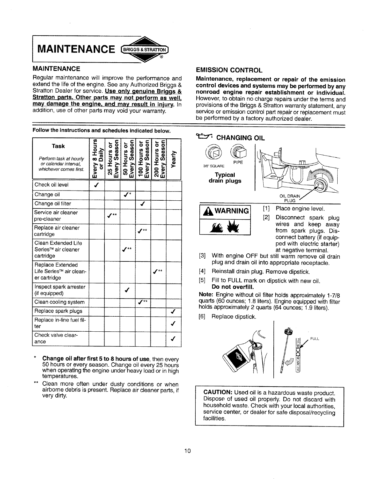
MAINTENANCE
MAINTENANCE
Regular maintenance will improve the performance and
extend the life of the engine. See any Authorized Briggs &
Stratton Dealer for service. Use only genuine Briggs &
Stratton parts. Other parts may not perform as well,
may damage the engine, and may result in injury. In
addition,use of other parts may void your warranty.
Follow the instructions and schedules indicated below.
EMISSION CONTROL
Maintenance, replacement or repair of the emission
control devices and systems may be performed by any
nonroad engine repair establishment or individual.
However, to obtain no charge repairsunderthe terms and
provisions of the Briggs & Stratton warranty statement, any
service or emission control part repair or replacement must
be performed by a factory authorized dealer.
•= = =
Task 5> _ _o_ _ _o=
Perform task at hour/y oo t't _t.13 _ _ OtJ_ _t,tj
or calendar interval,
whichever comes first. =_ "7- _ .1- _ "1- >, -r. _ _.
,., ,,, ,,, .-,,>,.,,>,
Check oil level _"
Changeoil J*
Change oil filter ,/"
Serviceair cleaner
pre-cleaner
Replace a r cleaner ,/.**
cartndge
Clean ExtendedLife
SeriesTM air cleaner ,_**
cartridge
Replace Extended
LifeSeriesTM air clean- ,[**
er cartridge
Inspectsparkarrester
(if equipped)
Cleancooling system ,f**
Replace spark plugs ,f
Replace in-linefuel fil-
ter J
Checkvalve clear- j
ance
CHANGING OIL
PIPE
3/8" SQUARE
Typical
drain plugs
OIL DRA
[1]
[2]
[3]
[4]
[5]
Place engine level.
Disconnect spark plug
wires and keep away
from spark plugs. Dis-
connect battery (if equip-
ped with electric starter)
at negative terminal.
With engine OFF but still warm remove oil drain
plug and drain oil into appropriate receptacle.
Reinstall drain plug. Remove dipstick.
Fill to FULL mark on dipstick with new oil.
Do not overfill.
Note: Engine without oil filter holds approximately 1-7/8
quarts (60 ounces; 1.8 liters). Engine equipped with filter
holds approximately 2 quarts (64 ounces; 1.9 liters).
[6] Replace dipstick.
" FULL
*Change oil after first 5 to 8 hours of use, then every
50 hours or every season. Change oil every 25 hours
when operatingthe engineunderheavy load or inhigh
temperatures.
** Clean more often under dusty conditions or when
airbornedebris is present. Replace air cleaner parts, if
very dirty. CAUTION: Used oil is a hazardous waste product.
Dispose of used oil properly. Do not discard with
household waste. Check with your local authorities,
service center, or dealer for safe disposal/recycling
facilities.
10

MAINTENANCE
CHANGING OIL FILTER
Change oil filter after every 100 hours or every season.
[1] Drain engine oil and remove oil filter.
[2] Before installing new filter, lightly oil filter gasket with
fresh, clean oil.
[3] Screw filter on by hand until gasket contacts oil filter
adapter. Tighten 1/2 to 3/4 turn more.
[4] Add fresh oil. Fill to FULL line on dipstick.
[5] Start and run engine at idle to check for leaks.
[6] Stop engine. Re-check oil level. Add oil if required.
OIL PRESSURE
If oil pressure drops below 4-6 psi (.2-.4 kg/cm2), an oil
pressure switch (if engine is equipped) will either activate a
warning light or stop the engine. Check oil level with
dipstick. If oil level is between ADD and FULL mark on
dipstick, Do not try.to restart engine. Contact an Authorized
Briggs & Stratton Service Dealer. Do not operate engine
until oil pressure is corrected.
If oil level is below ADD mark on dipstick, add oil to bring
level to FULL mark. Restart engine and check oil pressure.
If pressure is normal, continue to operate engine.
Note: Oil pressure gauge, if engine is equipped, is supplied
by manufacturer of equipment.
AIR CLEANER
Always replace cartridge and pre-cleaner if damaged.
CAUTION: Do not use _ CARTRIDGE
pressurized air or solvents
to clean cartridge. FOAM
PRE-CLEANER
Pre-cleaner
To clean, wash in liquid detergent and water. Squeeze dry
in a clean cloth. Saturate with engine oil. Remove all
excess oil on pre-cleaner by squeezing inside a clean
absorbent cloth.
REMOVING AND INSTALLING AIR CLEANER
[1] See illustrations for disassembly and reassembly of
your air cleaner style.
[2] Carefully remove air cleaner cartridge and pre-clean-
er to prevent debris from entering carburetor.
[3] Install pre-cleaner in base with mesh side up.
[4] Install cartridge on pre-cleaner.
[5] Replace cover. To ensure proper fit, tabs must be
hooked into slots. Tabs are painted a different color in
some instances.
[6] Latch handle or tighten knobs completely to secure
cover.
I CAUTION: Improper installation of air cleaner
cover may cause damage to engine.
EXTENDED LIFE SERIES T"CARTRIDGE ONLY
This filter, IF STAMPED 'WASHABLE', can be washed
with warm water and mild soap.
IMPORTANT: Rinse in
tap water with SCREEN
side up allowing dirt and
debris to filter out. Leave
filter to dry overnight be-
fore reinstalling.
\
\

MAINTENANCE
ENGINE AND ENGINE PARTS
We recommend that you see an authorized Briggs & Stratton Service Dealer for all maintenance and service of the engine
and engine parts. Use only genuine Briggs & Stratton parts.
If you perform any maintenance on the engine, first disconnect the spark plug wires
WARNING from the spark plugs, and disconnect the battery at the negative terminal (electric
starter engines only) to prevent unintentional sparking. Unintentional sparking can
result in fire or electric shock. Unintentional start-up can result in entanglement,
traumatic amputation or laceration. Use only correct tools.
WARNING • Do not strike the flywheel with a hammer or hard object because the flywheel may
later shatter during operation.
• Do not tamper with governor spring, links or other parts to increase engine speed.
MUFFLER
Replacement parts for theWARNING muffler must be the same and
installed in the same position
as the original parts, other-
wise fire can occur.
If muffleris equipped with spark
arrestor screen, remove
screen for inspection.Replacescreen if damaged or plugged.
FUEL SYSTEM
WARNING Replacement parts for fue!
system (cap, hoses, tanks,
filters, etc.) must be the same
as original parts, otherwise
fire can occur.
FUEL FILTER (if equipped)
WARNING
__/_ FILTER
[1] Disconnect spark plug
wires and keep away
from spark plugs.
[2] Drain fuel tank or close
fuel shut-off valve before
replacing fuel filter.
Otherwise, fuel can leak
out, creating a fire/explo-
sion hazard.
AIR COOLING SYSTEM
Debris may clog the engine's air cooling system. Remove
blower housing and clean area shown to prevent overheat-
ing and engine damage.
CLEAN AREAS UNDER
AIR CLEANER BLOWER HOUSING
KNOBS /OF ALL DEBRIS
_ AI_NTAKE
screws
SPARK PLUG
Use only Briggs & Stratton Spark Tester (part number
19368) to check for spark.
Note: In some areas, local .o3o"(o.76mm)
law requires using resistor ..y..--_WtREGAGE
spark plug to suppress igni-
tion signals. If this engine
was originally equipped with
resistor spark plug, use \
same type for replacement. \
VALVE CLEARANCE
Check valve clearance yearly. (See Tune-up Specifications
on page 6).
12

CLEANING DEBRIS
I CAUTION: Do not use water to clean engine parts. I
Water could contaminate fuel system. Use a brush I
or dry cloth.
_i_ WARNING Engine parts should be kept
clean to reduce the risk of
overheating and ignition of
accumulated debris. This is
especially important if cutting
tall grass. Daily or before every use, clean accumulated
debris from engine.
Keep linkage, springs and controls clean.
Keep area around and behind muffler free of any combus-
tible debris.
Keep muffler area clean and muffler in working order. Daily
or more often, before running engine, clean muffler area to
remove all grass and combustible debris. If engine muffler
is equipped with spark arrester screen, remove for cleaning
and inspection. Replace if damaged or plugged.
I B.,GGS.ST. T O.)MAINTENANCE
ROTATING SCREEN
Rotating Screen
CLEAN
Linkage, Springs and Controls
I
CONTROL ADJUSTMENTS
_WARNING
Prevent unintentional starting.
Before performing adjustments:
• Remove spark plug wires from spark plugs.
• Disconnect battery at negative terminal (only
engines with electric start).
!
sT.. o.;IADJ USTME NTS I
I
TO ADJUST REMOTE CHOKE CONTROL
PULL TO CHOKE
WIRE AND
CASING
CASING CLAMP SCREW
[1] Remove air cleaner.
[2] Move choke control to CHOKE or START position.
(Carburetor choke should be completely closed.)
[3] If not, loosen casing clamp screw.
[4] Then move casing, wire and engine choke lever in
direction shown until choke is _ closed.
[5] Tighten casing clamp screw. Replace air cleaner.
13

ADJUSTMENTS
TO ADJUST REMOTE THROTTLE CONTROL
If the engine does not start or if it runs roughly, the remote
throttle control may need adjustment. See your authorized
Briggs & Stratton dealer or follow the instructions below.
THROTTLE
STO P
FAST
[1]
[2]
SWIVEL
CASING
CLAMP
SCREW
Move throttle control to FAST. (Swivel should be
against throttle stop.)
If not, loosen casing clamp screw. Move casing
and wire in direction shown by arrow until swivel is
against throttle stop.
[3] Tighten casing clamp screw.
CARBURETOR ADJUSTMENT
WARNING
The manufacturer of the equipment on which this
engine is installed specifies top speed at which the
engine will be operated. DO NOT EXCEED this speed.
Differences in fuel, temperature, altitude or load may
require minor carburetor adjustment. Air cleaner and air
cleaner cover must be assembled to carburetor before
starting engine.
The carburetor on this engine is low emission. It is not
adjustable except for idle speed. Governed idle speed
is1750 rpm, set at the factory.
TO ADJUST CARBURETOR
Double Barrel
IDLE
SCREW
CARBURETOR
THROTTLE
LEVER
Single Barrel
IDLE
SPEED
SCREW
CARBURETOR
THROTTLE
LEVER
14
[1] Start engine and warm up approximately 5 minutes
before adjusting.
[2] With engine running, place throttle control in SLOW
position.
[3] Rotate carburetor throttle lever against the idle speed
screw and hold it.
[4] Turn idle speed screw to obtain 1500 rpm.
[5] Release carburetor throttle lever. Movethrottle control
to FAST position. Engine should accelerate smoothly.
Note: Engines operated at about 3000 feet (900 meters) or
higher above sea level may require a high altitude carbure-
tor main jet. If erratic performance is observed, contact a
Briggs & Stratton Authorized Service Dealer for cost to
install/purchase a high altitude carburetor main jet.

SERVICE & STORAGE
PARTIAL LIST OF GENUINE BRIGGS &
STRATTON PARTS
BRIGGS & STRATTON
PART PART NO. (or equivalent)
Extended Life Series TM air cleaner cartridge 695667
Air cleaner cartridge
Air cleaner pre-cteaner
Oil
Extended Life SeriesTM oil filter
Oil filter
Fuel filter (2.75" length)
Fuel filter (3.5' length)
Gas additive
499486
273638
100005-or-100028
696854
492932-or-5049
691035
695666
5041
Resistor spark plug (Champion RC12YC) 491055
Static suppressionspark plug (Champion QC12YC) 691043
Long life platinum spark plug 696202 -or- 5066
Spark plug wrench 19374
Spark tester 19368
Oil pump kit 5056
(uses standard electric drill to remove oil from engine quickly)
SERVICE
See an Authorized Briggs & Stratton Service Dealer. Each
one carries a stock of Genuine Briggs & Stratton Parts and
is equipped with special service tools. Trained mechanics
assure expert repair service on all Briggs & Stratton
engines• Only dealers advertising as "Authorized Briggs &
Stratton" are required to meet Briggs & Stratton standards.
When you purchase equipment powered by a 1t_5_ _ iK
Bnggs & Stratton engine, you are assured of
highly skilled, reliable service at more than _!_,,_'
30,000 Authorized Service Dealers "_t_"
worldwide, including more than 5,000 Master
Service Technicians• Look for these signs
wherever Briggs & Stratton service is offered. " _ "
You may locate your nearest Authorized Briggs & Stratton
Service Dealer in our dealer Iocator map on our web site
www.briggsandstratton.com or in the "Yellow Pages _M''
r_ directory under "Engines, Gasoline" or "Gasoline
T_ Engines," or "Lawn Mowers" or similar category.
Note: Walking fingers logo and "Yellow Pages" are regis-
tered trademarks in various jurisdictions.
An illustrated shop manual includes
common specifications and detailed in-
formation covering adjustment, tune-up
and repair of Briggs & Stratton twin
cylinder, OHV, 4 cycle engines. It is
available for purchase from an Autho-
rized Briggs & Stratton Service Dealer or
you can order it from the factory. Write:
Briggs & Stratton Corporation
Attn: Service Division
P. O. Box 1144
Milwaukee, Wl 53201
Pa_ No. 273521
15
.----__
• _-
Co
c
me-
.__o o
:=oo
_.-_o
o m

SERVICE & STORAGE [B.,QGS.ST...o.]
STORAGE
Engines stored over 30 days need special attention•
[1] To prevent gum from forming in fuel system or on
essential carburetor parts:
a) if fuel tank contains oxygenated or reformulated
gasoline (gasoline blended with an alcohol or an
ether), run engine until it stops from lack of fuel, or b) if
fuel tank contains gasoline, either run engine until it
stops from lack of fuel, or add a gasoline additive to the
gas inthe tank. (See parts list. Single - use pouches of
gas additive are available from your service dealer.) If
you use a gas additive, run the engine for several
minutes to circulate the additive through the carburetor•
Then, engine and fuel can be stored up to 24 months.
[2] While engine is still warm, change oil.
[3] Remove spark plugs and pour about 1 oz. (30 ml) of
engine oil into each cylinder. Replace spark plugs and
crank slowly to distribute oil.
[4]
[5]
Clean engine of surface debris, chaff or grass•
A WARNING Store in a clean, dry area.
Do not store in same area
as a stove, furnace, water
heater, or other appliance
that uses a pilot light or
has a device that can
create a spark.
,==
I C I,.
I=O
! o.o o
u} t,/) _- -
It"- "P'_
I"5 '_ x-,
--_ O"_
I __=,_ _
I.---_ -_ E
----'E0--
ILZm n'_= z
L
o
o
r_
I
8
Q.--
S
0
co
c
o o
>,r-
m o
•_= o
Eo&
m o
_mc
._ 1.1.!
16

Effective January 1, 2003 replaces all undated Warranties and all Warranties dated before January 1, 2003
LIMITED WARRANTY
Briggs & Stratton Corporation will repair or replace, free of charge, any part(s) of the engine that is defective in material or workmanship or both.
Transportation charges on parts submitted for repair or replacement under this warranty must be borne by purchaser. This warranty is effective for the
time periods and subject to the conditions stated below. For warranty service, find the nearest Authorized Service Dealer in our dealer locater map
at www.briggsandstratton.com or by calling 1-800-233-3723, or as listed in the 'Yellow Pages TM'.
THERE IS NO OTHER EXPRESS WARRANTY. IMPLIED WARRANTIES, INCLUDING THOSE OF MERCHANTABILITY AND FITNESS FOR A
PARTICULAR PURPOSE, ARE LIMITED TO ONE YEAR FROM PURCHASE, OR TO THE EXTENT PERMITTED BY LAW ANY AND ALL IMPLIED
WARRANTIES ARE EXCLUDED. LIABILITY FOR INCIDENTAL OR CONSEQUENTIAL DAMAGES ARE EXCLUDED TO THE EXTENT
EXCLUSION IS PERMn-FED BY LAW. Some states or countries do not allow limitations on how long an implied warranty lasts, and some states or
countries do not allow the exclusion or limitation of incidental or consequential damages, so the above limitation and exclusion may not apply to you.
This warranty gives you specific legal rights and you may also have other rights which vary from state to state and country to country.
Vanguard TM
iii! iii!_i i_iiii i!i
Consumer Use
Commercial Use
Note the following special warranty periods: 2 years for ClassicTM engines in the European Union and Eastern European countries, for all consumer products in
the European Union, and for emission control systems on engines certified by EPA and CARB. 5 years for consumer use, 90 days for commercial use of Touch-N-
Mow@ starter on Quantum@ and Intek TM engines. Engines used in competitive racing or on commercial or rental tracks are not warrantied,
The warranty period begins on the date of purchase by the first retail consumer or commercial end user, and continues for the period of time stated in the table
above. "Consumer use" means personal residential household use by a retail consumer. "Commercial use" means all other uses, including use for commercial,
income producing or rental purposes. Once an engine has experienced commerciaI use, it shall thereafter be considered as a commercial use engine for pur-
poses of this warranty.
NO WARRANTY REGISTRATION IS NECESSARY TO OBTAIN WARRANTY ON BRIGGS & STRATTON PRODUCTS. SAVE YOUR PROOF OF PURCHASE
RECEIPT. IF YOU DO NOT PROVIDE PROOF OF THE INITIAL PURCHASE DATE AT THE TIME WARRANTY SERVICE IS REQUESTED, THE
MANUFACTURING DATE OF THE PRODUCT WILL BE USED TO DETERMINE THE WARRANTY PERIOD.
Bdggs &Strattonwelcomeswarrantyrepairand apologizesto
you for beinginconvenienced.AnyAuthorized Service Dealer
may perform warrantyrepairs. Most warranty repairs are
handled routinely, but sometimes requests for warranty
se_co may notbe appropriate.For example,warranty would
not applyif engine damageoccurredbecause of misuse,lack
of routine maintenance, shipping, handling, warehousing or
improperinstallation. Similarly, warranty is void if the serial
number of the engine hasbeen removedor the engine has
been altered or modified.
ffa customerdifferswiththe decision ofthe Service Dealer,an
investigationwillbe made to determine whetherthewarranty
applies.Ask the ServiceDealerto submitatIsupporting factsto
his Distributororthe Factoryfor review.Ifthe Distributoror the
Factory decides that theclaim isjustified, the customerwil be
fully reimbursed for those itemsthat are defective. To avoid
misunderstanding whichmight occur between the customer
and the Dealer,listed beloware some of thecauses of engine
failure that thewarranty does not cover.
Normal wear:
Engines, like atl mechanical devices, need periodic parts
service and replacementto performwelL Warranty wit_not
coverrepairwhennormalusehas exhaustedthe fifeof a partor
an engine.
Improper maintenance:
The Jifeofan enginedepends uponthe conditionsunderwhich
itoperates, end the care it receives. Some applications, such
as tilters, pumps and rotary mowers, are very often used in
dustyor dirtyconditions,whichcancause what appearsto be
prematurewear.Such wear,whencaused by dirt, dust, spark
plugcleaninggrit, or otherabrasivematerialthat has entered
the engine because of improper maintenance,is not covered
by warranty.
This warranty covers engine related defective material
and/or workmanship_and not replacementor refund
of the equipmentto whichthe engine may be mounted=
Nor duesthe warranty extendto repairsrequired because
of:
1. PROBLEMS CAUSED BY PARTS THAT ARE NOT
ORIGINAL BRIGGS & STRATI'ON PARTS.
2. Equipmentcontrolsorinstallationsthat preventstarting,
cause unsatisfactoryengine performance, or shorten
engine life. (Contact equipment manufacturer.
3. Leaking carburetors,cloggedfuel pipes, stickingvalves,
orotherdamage,causedby usingcontaminated orstale
fuel. (Useclean, fresh, lead-free gasotineand Briggs &
Stratton Fuel Stabilizer,Part No.5041.)
4. Parts whichare scored or brokenbecause an engine
was operated with insufficient or contaminated
lubricating oil, or an incorrect grade of lubricating oil
(check oil leveldailyor after every 8 hours of operation.
Refill when necessary and change at recommended
intervals.) OIL GARD® may not shut down running
engine. Engine damage may occur if oil level is not
properly maintained. Read Operating & Maintenance
Instructions.
5. Repair oradjustmentof associatedpartsorassemblies
such as cIutches,transmissions,remote controIs, etc.,
whichare not manufacturedby Briggs &Stratto;1.
6. Damage orwear toparts causedby dirt,which entered
the engine because of improper air cleaner
maintenance, re-assembiy,or use of a non-originalair
cleaner element or cartridge. (At recommended
17
intervals, cleanand re-oiltheOil-Foam® elementorthe
foam pre-cleaner, and replace the cartridge.)Read
Operating & Maintenance Instructions.
7. Parts damaged by over-speeding, or overheating
caused bygrass,debris,or dirt, whichplugsor dogsthe
cooling fins, or flywheel area, or damage caused by
operating theengine in aconfinedarea withoutsufficient
ventilation (Cleanfinson thecylindeficylinderheadand
flywheel at recommendedintervals.) ReadOperating &
Maintenancethst[uctions.
8. Engine or equipment parts broken by excessive
vibration caused by a loose engine mounting, Ioose
cutter blades, unbalanced blades or loose or
unbalanced impellers, improper attachment of
equipment to enginecrankshaft,over-speeding or other
abuse in operation.
9. A bent or brokencrankshaft, causedby striking a solid
object with the cutterblade of a rotary lawnmower, or
excessive v-belt tightness.
10. Routine tune-up oradjustment of the engine.
11. Engine or engine componentfailure, i.e., combustion
chamber, valves, valve seats, valve guides, or burned
starter motor windings, causedby the use of alternate
fuels such as, liquified petroleum,naturat gas, altered
gasolines,etc.
Warranty is availableonly through servicedealers which
have been authorized by Briggs & Straiten Corporation.
your nearest Authorized Service Dealer is listed in the
"Yellow PagesTM" of your telephone directory under
"Engines, Gasoline" or "Gasoline Engines," "Lawn
Mowers,"or similar category.

EMISSION CONTROL WARRANTY COVERAGE IS APPLICABLE TO CERTIFIED ENGI NES PURCHASED tN CALIFORNIA IN 1995 AND THERE-
AFTER, WHICH ARE USED IN CALIFORNIA, AND TO CERTIFIED MODEL YEAR 1997 AND LATER ENGINES WHICH ARE PURCHASED AND
USED ELSEWHERE IN THE UNITED STATES (AND AFTER JANUARY 1, 2001 IN CANADA).
The California Air Resources Board (CARB), U.S.
EPA and B&S are pleased to explain the Emission
Control System Warranty on your model year
2002 and later small off-road engine (SORE). In
Califomia, new small off-road engines must be de-
signed, built and equipped to meet the State's
stnngent antFsmog standards.
Elsewhere in the United States, new non-road,
spark-ignition engines certified for model year
1997 and later must meet similar standards set
forth by the U.S. EPA. B&S must warrant the emis-
sion control system on your engine for the periods
of time listed below, provided there has been no
abuse, neglect or improper maintenance of your
small off-road engine.
Your emission control system includes parts
such as the carburetor, air cleaner, ignition sys-
tem, muffler and catalytic converter. Also in-
cluded may be connectors and other emission
related assemblies.
Where a warrantable condition exists B&S will
repair your small off-road engine at no cost to
you including diagnosis, parts and labor.
Small off-road engines are warranted relative to emission control parts defects for a period of two years, subject to provisions set forth below. If any
covered part on your engine is defective, the part will be repaired or replaced by B&S.
As the small off-road engine owner, you are re-
sponsible for the performance of the required
maintenance listed in your Operating and Main-
tenance Instructions. B&S recommends that
you retain all your receipts covering mainte-
nance on your small off-road engine, but B&S
cannot deny warranty solely for the lack of re-
ceipts or for your failure to ensure the perfor-
mance of all scheduled maintenance.
As the small off-road engine owner, you should
however be aware that B&S may deny you war-
ranty coverage if your small off-road engine or a
part has failed due to abuse, neglect, improper
maintenance or unapproved modifications.
You are responsible for presenting your small
off-road engine to an Authorized B&S Service
Dealer as soon as a problem exists.
The undisputed warranty repairs should be
completed in a reasonable amount of time, not
to exceed 30 days.
If you have any questions regarding your war-
ranty rights and responsibilities, you should con-
tact a B&S Service Representative at
1-4t 4-259-5262.
The emission warranty is a defects warranty.
Defects are judged on normal engine perfor-
mance. The warranty is not related to an in-use
emission test.
The following are specific provisions relative to your Emission Control Defects Warranty Coverage.
regulated engines found in the Operating and Maintenance Instructions.
Warranted Parts
Coverage under this warranty extends only
to the parts listed below (the emission con-
trol systems parts) to the extent these parts
were present on the engine purchased.
a. Fuel Metering System
• Cold start enrichment system
• Carburetor and internal parts
• Fuel Pump
b. Air Induction System
• Air cleaner
• Intake manifold
c. Ignition System
• Spark plug(s)
• Magneto ignition system
d. Catalyst System
• Catalytic converter
• Exhaust manifold
• Air injection system, Pulse valve
e. Miscellaneous Items
• Vacuum, temperature, position,
time sensitive valves
and switches
• Connectors and assemblies
2. Length of Coverage
B&S warrants to the initial owner and each
subsequent purchaser that the Warranted
Parts shall be free from defects in materials
and workmanship which caused the failure
of the Warranted Parts for a period of two
years from _he date the engine is delivered to
a retail purchaser.
3. No Charge
Repair or replacement of any Warranted
Part will be performed at no charge to the
owner, including diagnostic labor which
leads to the determination that a Warranted
Part is defective, if the diagnostic work is
performed at an Authorized B&S Service
Dealer. For emissions warranty service
contact your nearest Authorized B&S Ser-
vice Dealer as listed in the "Yellow Pages"
under "Engines, Gasoline," "Gasoline En-
gines," "Lawn Mowers," or similar category.
4. Claims and Coverage Exclusions
Warranty claims shall be filed in accordance
with the provisions of the B&S Engine War-
ranty Policy. Warranty coverage shall be ex-
cluded for failures of Warranted Parts which
are not original B&S parts or because of
abuse, neglect or improper maintenance as
It is in addition to the B&S engine warranty for non-
set forth in the B&S Engine Warranty Policy.
B&S is not liable to cover failures of War-
ranted Parts caused by the use of add-on,
non-original, or modified parts.
5. Maintenance
Any Warranted Part which is not scheduled
for replacement as required maintenance or
which is scheduled only for regular inspec-
tion to the effect of "repair or replace as nec-
essary" shall be warranted as to defects for
the warranty period. Any Warranted Part
which is scheduled for replacement as re-
quired maintenance shall be warranted as to
defects only for the period of time up to the
first scheduled replacement for that part. Any
replacement part that is equivalent in perfor-
mance and durability may be used in the per-
formance of any maintenance or repairs,
The owner is responsible for the perfor-
mance of all required maintenance, as de-
fined in the B&S Operating and Maintenance
Instructions.
6. Consequential Coverage
Coverage hereunder shall extend to the fail-
ure of any engine components caused by
the failure of any Warranted Part still under
warranty.
8dggs & StrattonEnginesAre Made UnderOneOr Mote Of TheFetlowingPalents: DesignD-247,177(0ther PatentsPending)
6,325,036 6,077,063 5,819,5t3 5,606,948 5,497,679 5,235,943 5,138,996 4,998,958
6,284,123 6,064,027 5,8t3,384 5,606,851 5,320,795 5,197,425 5,086,890 4,977,879
6,260,529 6,014,808 5,765,713 5,548,955 5,271,363 5,197,422 5,070,829 4,971,219
6,230,678 5,894,715 5,64&025 5,546,901 5,269,713 5,191,864 5,058,544 4,895,119
6,202,616 5,852,951 5,642,701 5,503,t25 5,265,700 5,188,069 5,040,644 4,819,593
8,116,212 5,823,153 5,619,845 5,501,203 5,243,878 5,186,142 5,009,208 4,719,682
18
4,633,555 4,430,984 DES 308,871
4,630,498 DES 308,872
4,522,080 DES. 309,457
4,520,288 DES. 356,951
4,512,499 DES 361,771
4,453,507 DES. 375,963

(Cette page ne s'appIique que pour le Canada et les Etats-Unis)
La Corporation Briggs & Stratton (B&S), le California Air Resources Board (CARB)
et Io Bureau de protection envtronnementala des Etats-Unis (US EPA)
G0rantie sur le syst_me d'_chappement (Garantie contro les d_fectuosit6s, droits et ob get ons du propr _ta re)
LA GAP,_NT1ESUF_LE SYSTEMED'ECHAPPEMENTEST APPUCABLE SUR LES MOTEURS VANTESQUI ONTE_'EACHETESETUTIUSESAILLEURSAUXETATS-UNIS(ETAPRt_SLE1ER
CE.RTIFIESACHETESENCAUFORNIEEN199_ETLESANN_ES SUIVANTESETQUl S(_NTUTI- JANVIER200t AU CANADA).
USESEN CAUFORNIE,AJNSIQU'AUXMODELESCERTIFIESDE 1997 El- LESANNEES SUI-
D_claraUon de garanUe sur le syst_me d'6chappement pour la Californie, les Etats-Unis
LeCaliforniaAir ResourcesBoard (CARB_,ie Bureau am_ricain de protectionenvironnementale pementde votre moteur pour la p_fiode de temps mentionn_eci-contre, saut s'il a fair ]'objet
(US, EPA)et B& S sontheureux d'expliquer]agarantie surle syst_med'_chappement des petits d'abus,de n_gtigenceou d'un entretien inappropri_.
moteurs hors-route de votre module2000 et des ann_es uif6rieures SORE. EnCalifurnie, tes Votresyst6medecontr61ed'_chappomentcomprenddespi6oestellesquelecarburateur letiltxe
nouveaux petitsmoteurs horsroutedovent 6trecongas,construts et _qu p_spourrencontrerles air,le syst_me #ignition, lesilencieux et le convertisseurcatalytique, ti peut aussi comprendreIes
standards rigoureux d'antipollution.Ailleursaux Etats-Unis, los nouveaux muteurs hors route & connecteurset autres pi6cesreli6es & l'_mission.
bougie d'allumagecertifies pour lesmodulesde 1997 et plus doiventrencontrerdes normes simi- Lorsqu'ily acondition&garantie, B&S r_pareragratuitementvotrepetitmuteurhors-route incluant
taires raisesde I'avantpar le U.S.EPA. Briggs& Strattongarantit le systSmede contrSled'_chap- le diagnostic, los pi_ceset la main d'oeuvre.
Couverture de garantie Briggs & Stratton contre toute d_fectuosit6 du syst_me de contr61e d'_chacoement
Los petitsmoteurshorsroutesontgarantiscontre;ad_fectuosit_des pi_oesdusyst_mede contr6- te quelle pi_cade votre rnoteur couverte parca_e ga antie est d_fectueuse,eile serar_par_e ou
_eo'_cnappementpourone p_riooeoe 2 arts,sujetteauxconditions stipol6esci-contre. Sin'impor- remplac6e par B&S,
Responsabilit_s du propri6taire
Entant quepropri_taired'unpetitmoteurhers route,vous _tesresponsable deveiller _l'ex_cution Voos avez ]arespon-_abi]it_d'apportervotrepo imoteur hers route_un d_ta antautoris_ B&S
de !'entretienrequistelque stipul_dartsvotremanueld'op_ration et d'entretien.B&Svous recom- aussit6tque survientun probl_me. Losr_parationssous garantiedoivent6ire compl6t_esdans un
mande deconservertousles re;uscnuvraetlos travaux d'entretiende votre petitmoteurhors rou- d_lai raisonnable ne devant pas exc_der 30 ours.
to, mais B&S ne poutrefuser lagarantie en raisond'absence de re_usou pour d6faut d'avoir suivi Si vous avez desquestions relativement & votre garantie, vos droits et responsabilit_s,veuiUez
tout 1'6ch_ancierdu programmed'entrstien, communiqueravec un repr6sentantde service B&S au num_ro1-414-259-5262.
Enrantque propri_taired'unpetitmoteurborsroute,vousdevez _treinform_ que B&Spout refuser Lagarantie dusysteme d'_chappementest unegarantie contreles d_fuctuosit_s.Les d_fectuosi
d'honorer cette garantiesila d_fectuosti_devotremoteur oud'une pantiede votremoteur estdue ._ tes sont ug_ns en fonctiond'une utilisation normale du moteor,La garantie n'est pasreliSe_ on
unemptoi abusif, une n_gligenca,un entretienincorrect oo une modificationnon approuv_e, test d _chappementeffectu__ rint_rieur.
Dispositions de la garantie du syst_me d'_chappement Briggs & Stratton
Ce qui suitconcerneIns dispositionssp_ciflquesrelativement &votre garantiesur le syst_mede contr6ied'bchappement.Cestuneaddition _ la garan ie B&S pouresmoteurs non rbglementbscontenue
dans le manuel d'entretieo et d'utilisation.
1. Pi_ces sous garantie
La couverturede cettegarantiene #applique que sur los pi_ceslist6es ci-contre(les parties
dusyst_mede contr61ed'_chappement)dans lamesure o_ cespieces_taient pr_sentessurle
muteur au momentde I'achat.
a. Syst_me de dosagedu carburant
• Syst_med'endchissementde dbmarrage & froid
•Cartiuratearet partiesinternes
• Pompe _essence
b. Systbme d'inductiond'air
•Fi_tre_air
•Tubulumd'admission
c. Syst_me d'ignition
• Bougiesd'allumage
• Syst_med'allumage _lectromagn_tique
d. Syst_me catalyseur
• Convertisseurcatalytique
• Coflecteurd'_chappement
• Systbmed'injection d'airoo& pulsion
e. Autres pibcesutilis_es dans les syst_mes ci-haot mentionn6s
• Soupapes et interrupteursde d_pression, de temperature, de position.
• Connecteurset assemblages,
2, Dur_e de la couverture
B&S garantit]epropri_taireinitialettousIns acheteurssubs_quentsque les pi_cessousga-
rantiesootexemptesdevice demati_reou defabricationqui pourraientcauserdesd_fectunsi-
t_s des pi_cassousgarantie pourone p6riode de deux arts& partirde la date& laqueUele mo-
teura _t_livr_ &racheteur.
3. AucunsFrais
La rdparation ou le remplacament de toute piecesous garantie sera effectu6esans aucuns
frais pourle propri_taire,inciuantles frais de maind'ceuvrepourle diagnosticafinde d_termi-
netsi la pi_casous garantieest d_fectueuse,conditionnel &ce que le diagnosticsoit effectu6
chezund_taillant autods_B&S. Pourlagarantie relativeau systeme d'_chappement,commu-
niquezavec le d6taillant autoris_ B&S le plus prochetel que list_dans Ins pagesjaanns de
votreIocalit_ soas la rubdquemoteur &essence, tondeuseou autrecat_gode similaire.
4. Rdclamations et exclusions de la oouverture.
Los r6clamations de garantie doivent _tre compl_t_es an accord a'veclos dispositionsde la
politiquede garantie B&S. La garantie ne couvrepas Ins d_fectuosif_sde pi_cesqui nesoot
pasdes pi_cesd'origineB&Sou danslecas d'abus n_gligence oud'un entretieninappropri6.
La garant e B&Sne couvrepasles d_fectuosti_s de pi_cessoas garantiequi ont fairI'objet
d'ajouts, ont _t_modifi_esoude pi_cesqui ne son'_pas des pi_cas B&S d'origine.
5. Entretien
Toutepiecesous garantiequi n'estpas remplac_e aumoment requisselonle manuel #entre-
tien ouqui nst planifi_eseulement pouroneinspection r_guli_re sous la mention ,, r_parer ou
remplacersi n_cessaire _ est garantie contre toute d_fecfuosit_pour la p_riodede garantie.
Toutepi_casous garantiequi est planifi_epourunremplacementtel que requis dans I'entre-
tien estgarantiecontretouted_fectuosit_ seulementpour la p_riodede temps qui va usqu'au
premier remplacementpr_v_ pourcatte piece.Toutep_ce de rempacement _quivalenteen
performanceet durabilit_ pout_tre utilis_e pour!'entmtien ou la r_paration.Le propri_taireest
responsable deI'ex_cution de tout entretien requis telque d_fini dans le manuel d'instruction
B&S surrentretien et ta r_paration,
6. Couverfure ind;recte
Lacouvertureci-contres'6tend &route d_fecfuosit_descomposantesdu moteurcaus6e par
la d_fectuositdden'importe quelle pi_cacouverteparla garantieet pont lagarantieest encore
on wgueur.
Consultez los informations sur la p_riode de durabilit_ d'_mission et I'INDICE d'air sur I'_tiquette d'_mission de votre moteur
Losmeteors qui sootcertifiesconformesaux normes standardsd'_missionda CaliforniaAir Resources Board (GARB) -tier2, doivent afficher rinformation concemantla p_riode de durabilit_ du syst_me
d'_mission et I'INDICEd'air. Cette informationest indiqu_e sur les _tiquettes appos_es sur les moteurspar Briggs & Stratton.L'_tiquette du moteurindiqueralos renseignements concernantla certification.
Lap_riodede durabitit_d'_missionindiquele hombred'heuresd'utitisationnormalepour lequel lemoteurest certifi_conformeauxnormes d'_missionsousr_served'uo entretienappropri_telqu'indiqu_dans
le manuel d'op_ration et d'entretien Loscategoriessuivantessoot utilis6es:
Mod_r_ le moteurest certifi_conformepour 125 heuresd'utitisationnormale.
Interm_diaire le moteurest cartifi6 conformepour250 heuresd'utilisationnormale.
Prolong_ le moteorest certifi_conformepour500 heuresd'utilisationnormale.
Parexemple,one tondeusede mod_testandardest utilis_e environ20 _25heuresparannie. Parconsequent,la p_riodededurabilit_ d'_mission d'unmoteurdanala cat_gorieinterm_diairepourcetypede
tondeuse equivaut_ t0 a t2 ans.
L'indice d'air est unhombrequi d_critle niveau relatif d'6mission pour une cat_goriesp6cifique demoteur.P_usI'indice d'air est has,plus le moteurest _cologiqoe. Cette informationest indiqu_e sous une
forme graphiquesur I'_tiquette d'_r_ission.
A compter du 1erjuillet 2000, surveillez la p_riodede conformit_d'_mission sur les _tiquettes
Apr_s le 1erjuiltet2000, certainsmoteursB&S seront certifiesconfurmesaox normes environnementalesd'_missionstandard du United States Environmental ProtectionAgency (US EPA)Phase 2, Pour los
moteurs certifiSspourla Phase 2, la p_riode de conformit6 d'_mission mentionn_e sur tes _tiquettes indique ]ehombred'heures d'utilisation pour lequel le moteur rencontreIns normesf_d_rales. Pour los
moteurs de force moindreqae 225 co, la cat_gorie C= 125 heures, B = 250 heures et A = 500 heures, Pour los moteursde 225 cc et plus, la cat_goite C = 250 heures, B = 500 heures et A = 1000 heures,
Leremplacement du moteur portant Ie mod_le de s6rie 400000 est 656co. Le remplacamentdu moteur portantlemodele de s_rie 440000 est 725 co.
Ceci est unerepresentationdes_tiquettes d'_mission
quevousretrouverezsur lesmoteurscertifies:

BRIGGS & STRATTON
®

MANUFACTURER'S LIMITED WARRANTY FOR:
RESIDENTIAL USE ONLY
COMMERCIAL USE VOIDS WARRANTY
The limited warranty set forth below is given by Cub Cadet
LLC with respect to new merchandise purchased and used in
the United States, its possessions and territories.
"Cub Cadet" warrants this product against defects in material
and workmanship for a period of two (2) years commencing
on the date of original purchase and will, at its option, repair or
replace, free of charge, any part found to be defective in
materials or workmanship. This limited warranty shall only
apply if this product has been operated and maintained in
accordance with the Operator's Manual furnished with the
product, and has not been subject to misuse, abuse,
commercial use, neglect, accident, improper maintenance,
alteration, vandalism, theft, fire, water, or damage because of
other peril or natural disaster. Damage resulting from the
installation or use of any part, accessory or attachment not
approved by Cub Cadet for use with the product(s) covered
by this manual will void your warranty as to any resulting
damage.
Normal wear parts or components thereof are subject to
separate terms as follows: All normal wear parts or
component failures will be covered on the product for a period
of 30 days regardless of cause. After 30 days, but within the
two year period, normal wear part failures will be covered
ONLY IF caused by defects in materials or workmanship of
OTHER component parts. Normal wear parts and
components include, but are not limited to: batteries, belts,
blades, blade adapters, grass bags, rider deck wheels, seats,
snow thrower skid shoes, shave plates, auger spiral rubber,
and tires.
HOW TO OBTAIN SERVICE: Warranty service is available,
WITH PROOF OF PURCHASE, through your local authorized
service dealer. To locate the dealer in your area, check your
Yellow Pages, or contact Cub Cadet LLC at P.O. Box 361131,
Cleveland, Ohio 44136-0019, or call 1-877-282-8684, or log
on to our Web site at www.cubcadet.com.
This limited warranty does not provide coverage in the
following cases:
a. Log splitter pumps, valves, and cylinders have a
separate one year warranty.
b. Routine maintenance items such as lubricants, filters,
blade sharpening, tune-ups, brake adjustments, clutch
adjustments, deck adjustments, and normal
deterioration of the exterior finish due to use or
exposure.
c. Cub Cadet does not extend any warranty for products
sold or exported outside of the United States, its
possesions and territories, except those sold through
Cub Cadet's authorized channels of export
distribution.
d. Replacement parts that are not genuine Cub Cadet
parts.
e. Service completed by someone other than an
authorized service dealer.
f. Transportation charges and service calls.
No implied warranty, including any implied warranty of
merchantability of fitness for a particular purpose,
applies after the applicable period of express written
warranty above as to the parts as identified. No other
express warranty, whether written or oral, except as
mentioned above, given by any person or entity,
including a dealer or retailer, with respect to any product,
shall bind Cub Cadet. During the period of the warranty,
the exclusive remedy is repair or replacement of the
product as set forth above.
The provisions as set forth in this warranty provide the
sole and exclusive remedy arising from the sale. Cub
Cadet shall not be liable for incidental or consequential
loss or damage including, without limitation, expenses
incurred for substitute or replacement lawn care services
or for rental expenses to temporarily replace a warranted
product.
Some states do not allow the exclusion or limitation of
incidental or consequential damages, or limitations on how
long an implied warranty lasts, so the above exclusions or
limitations may not apply to you.
In no event shall recovery of any kind be greater than the
amount of the purchase price of the product sold. Alteration
of safety features of the product shall void this warranty.
You assume the risk and liability for loss, damage, or injury to
you and your property and/or to others and their property
arising out of the misuse or inability to use the product.
This limited warranty shall not extend to anyone other than the
original purchaser or to the person for whom it was purchased
as a gift.
HOW STATE LAW RELATES TO THIS WARRANTY: This
limited warranty gives you specific legal rights, and you may
also have other rights which vary from state to state.
IMPORTANT: Owner must present Original Proof of
Purchase to obtain warranty coverage.
CubCadetLLC,P.O.BOX361131CLEVELAND,OHIO44136-0019; Phone:1-877-282-8684
