CalAmp Wireless Networks BDD4T85-1 Paragon/PD User Manual TITLE
CALAMP WIRELESS NETWORKS INC. Paragon/PD TITLE
Contents
- 1. Annex A technical maual preliminary veersion
- 2. the technical manual a preliminary version
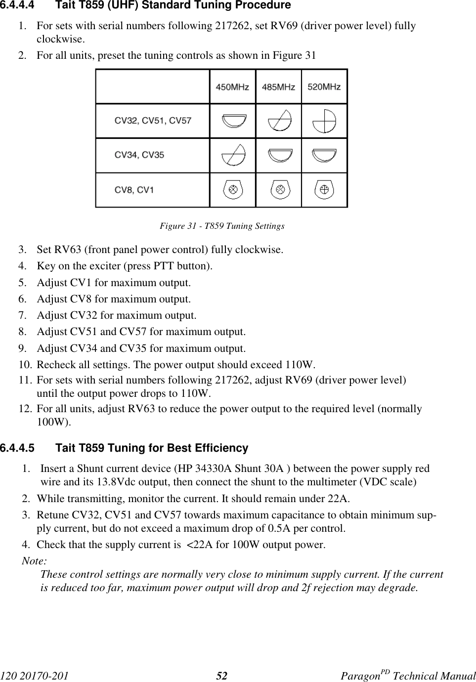
- 3. prelinimary version 202 nov 2001
- 4. preliminary version 100a
- 5. IVIS option technical appendix
- 6. proposed user manual
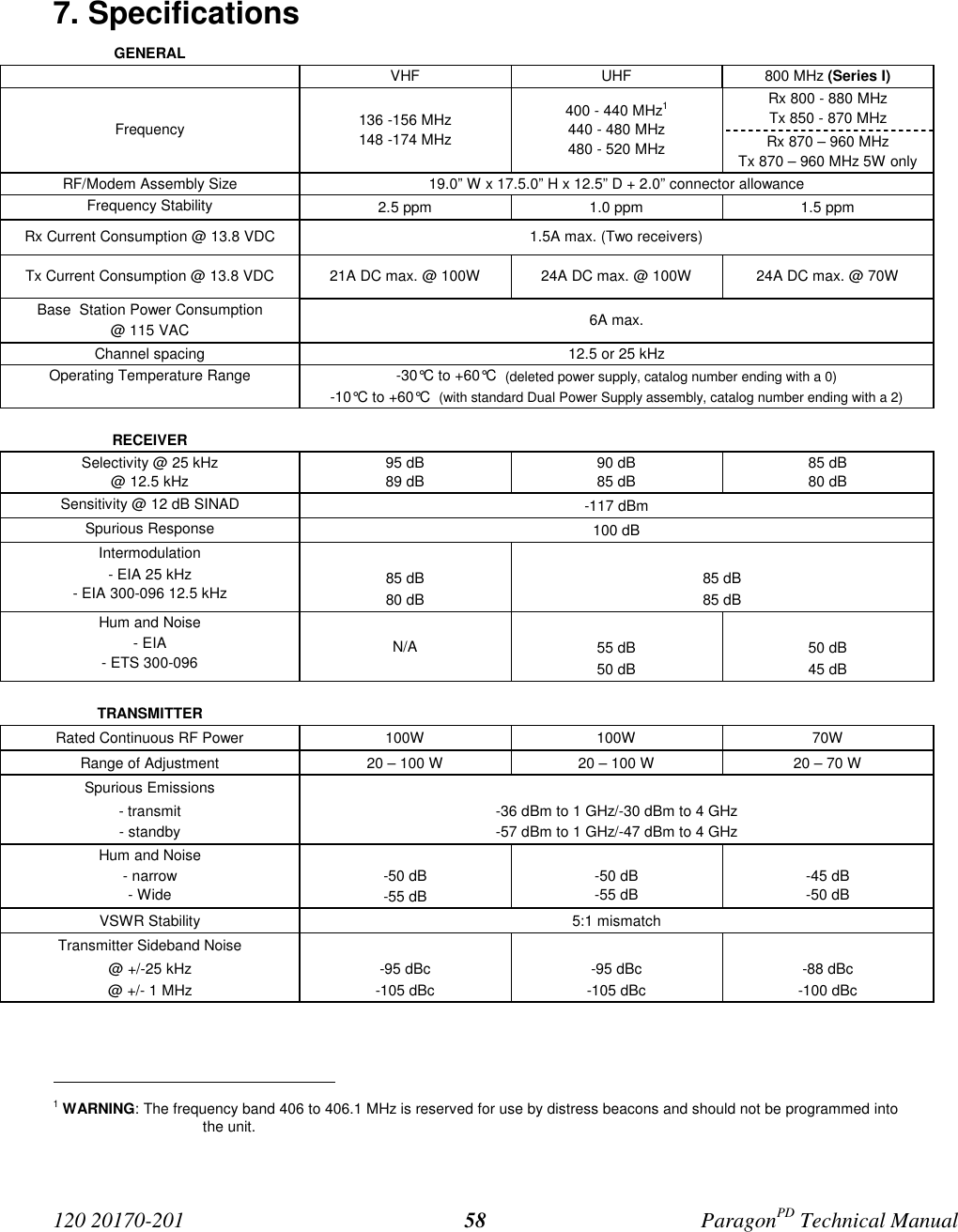
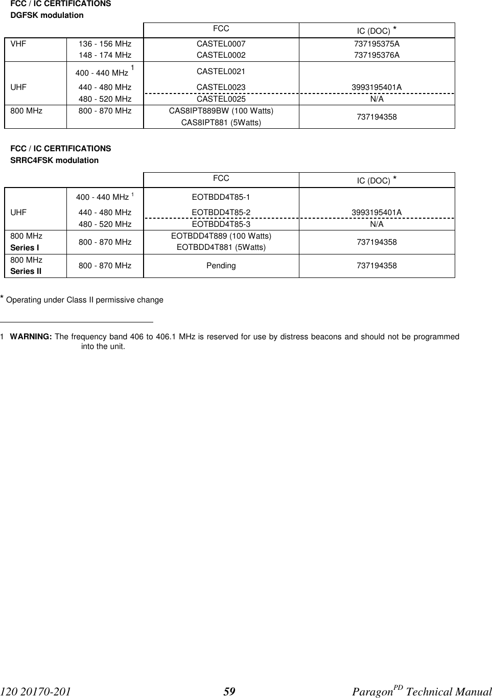
the technical manual a preliminary version

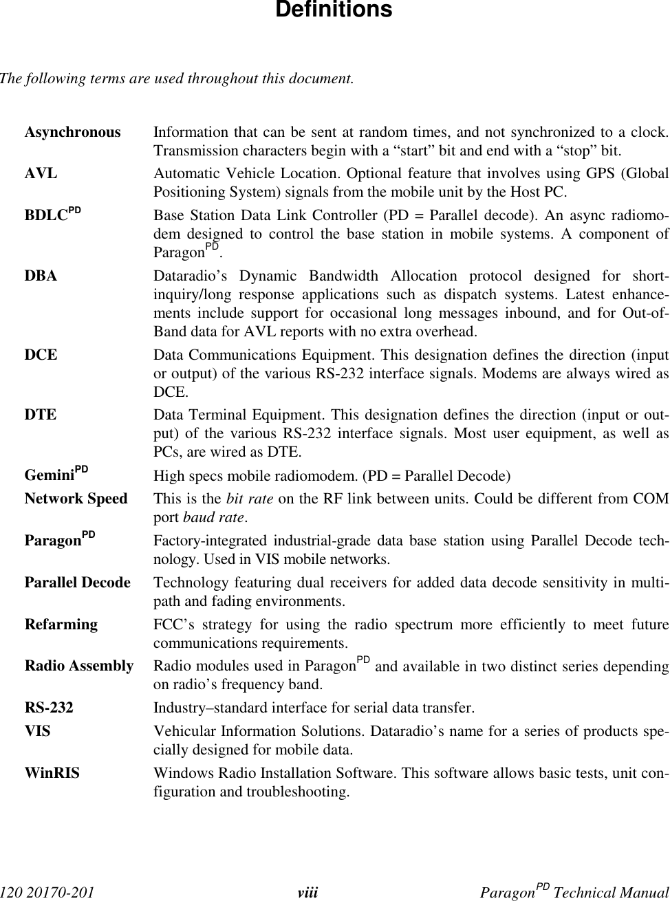


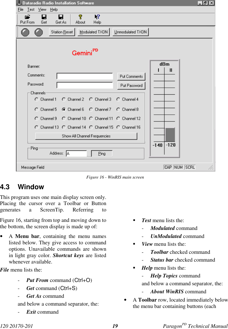
![120 20170-201 ParagonPD Technical Manual184. WinRIS programThe Windows Radio Installation Software(WinRIS) program is used to:• Check and troubleshoot ParagonPD.• Save an existing configuration.• Upload files for field configuring of units(Requires intervention with technical sup-port).To run the program, you will need:- A PC or portable computer running a 32-bitMS-Windows application:Win MEWin2000Win NTWin 9x (For Win 95, if COMCTL32.DLL has beenupdated to the most recent version andcopied to the \windows\system\ directory).Note:WinRIS does not operate under:- Win CE (embedded in PocketPC)- 16-bit Windows 3.x- A hard disk.- An available COM port.- A serial mouse, with its own driver installedis strongly recommend however most ac-tions can also be done using keyboardcommand4.1 OperationThis support program can be run in MS-Windows © mode.DO NOT have more than one copy of this pro-gram loaded at any given time in separate win-dows. Doing so creates COM port sharing con-flicts and failure to run the program alone re-sults in unexpected transmissions.Only left mouse button operation is supported.Any command or selection shown in gray is ei-ther unavailable or is awaiting another actionbefore activating.Help in the program is available at all points bypressing the F1 key. If a subject is highlighted,the help displayed will be context sensitive.4.2 To connect and startWinRISGeminiPD’s and ParagonPD’s share a commonWinRIS program available on diskette, Datara-dio p/n 980 03392-00n.Refer to the WinRIS Readme.txtfile for details on how to set theMS-Windows environment, andhow to connect, install and runthis program.In summary, before starting the WinRIS whenrunning MS-Windows, click on “Start”, then on"Run". Type the relevant path and variables onthe command line (or select by browsing) lead-ing to:WinRIS.EXE COM[x], [speed],8,n,1(where x is the PC COM port to be used) Ofcourse, the executable command may be usedalone without any variable added.Click on “OK”.It is also possible to create a PC desktop short-cut icon for WinRIS:• Start by right clicking anywhere on thedesktop,• Select New,• Select Shortcut and type the path as detailedabove directly on the command line (with orwithout variables).• Click Next,• Type in an applicable name for the shortcuticon,• Click Next• Select an icon (your choice) and• Click on Finish.Command line settings override the environmentvariable, if any.](https://usermanual.wiki/CalAmp-Wireless-Networks/BDD4T85-1.the-technical-manual-a-preliminary-version/User-Guide-148222-Page-26.png)
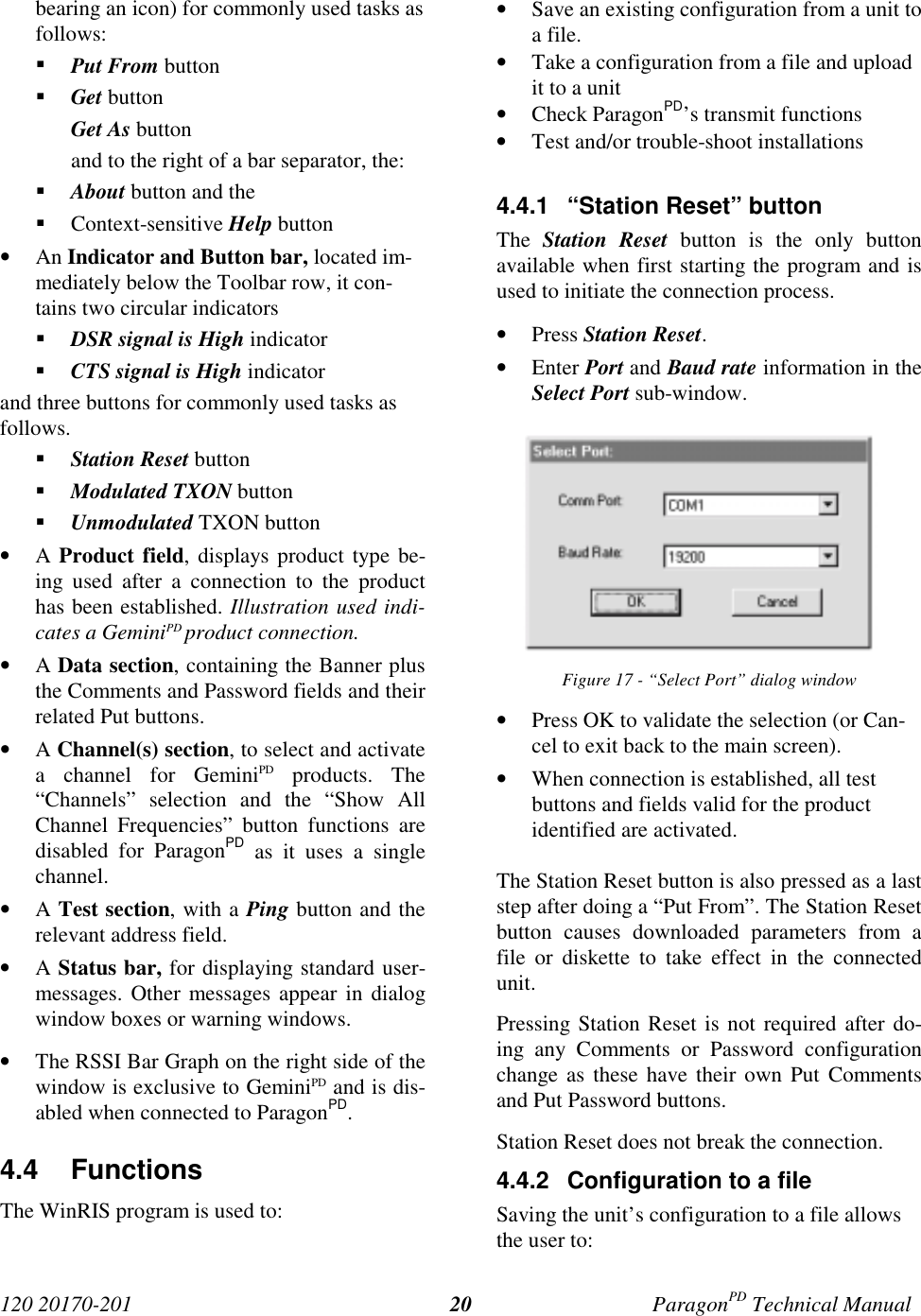
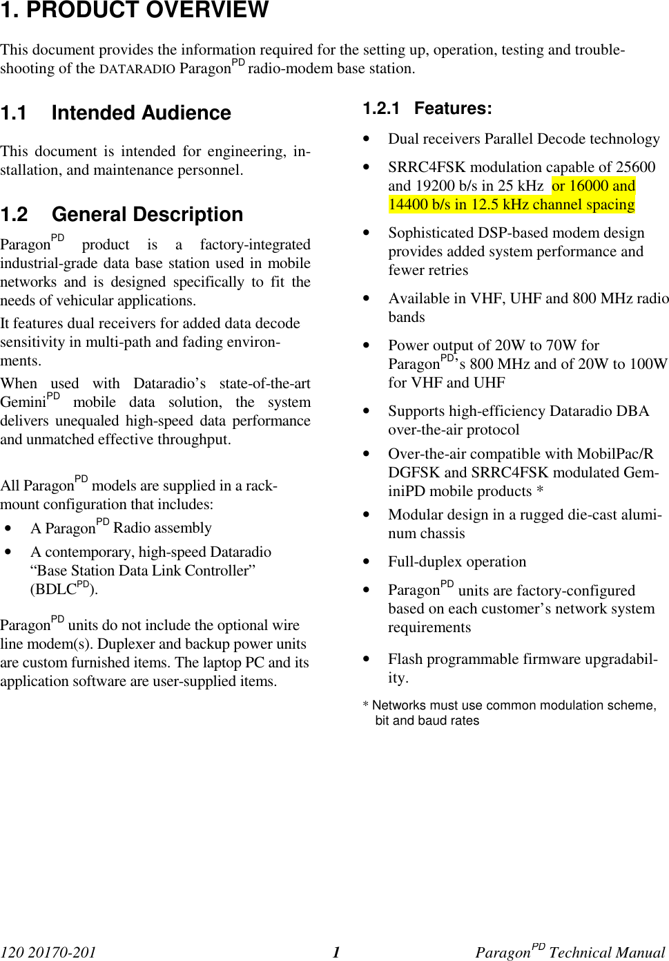
![120 20170-201 ParagonPD Technical Manual21• Subsequently restore the configuration.• Safeguard a copy as documentation of theconfiguration.Note: The configuration and status files areASCII files and may be e-mailed or faxed totechnical support when requested to do so.Warning:Do not make any changes to these files. Anychanges made to the configurations MUST bedone at factory or by Dataradio system engi-neering.4.4.2.1 “Get” buttonOn the menu bar, select “File”, then the “Get”command or press the “Get” button on theToolbar to:• Establish linking• Download and automatically save the con-nected unit’s configuration setting to a filenamed with the unit' serial number: TheWinRIS status bar will then report “All pa-rameters are successfully retrieved andsaved in file [unit' s/n].BP2. Any previousconfiguration in the program is overwritten.If you do not wish to overwrite an existing con-figuration or prefer to name the file yourself,use the “Get As” button.4.4.2.2 “Get As” buttonAfter communication is established using theConnect button, press the Get As button to:• Open the “File, Save As” window with theASCII file *.bp2 (already selected). Save theconnected BDLCPD’s operating characteris-tics (configuration setting) to a file, direc-tory or drive of your choice.The program will ask before overwriting anexisting file.• Status bar reports “All parameters are suc-cessfully retrieved and saved in [file-name]”.4.4.3 Configuration from a FileLoading a configuration from a file to a unit isuseful to:• Restore the operating characteristics of aunit (Requires intervention with technicalsupport.)• Carry out field updates using Dataradiosystem engineering supplied diskette(s).Warning:Do not make any changes to these files. Anychanges made to the configurations MUST bedone at factory or by Dataradio system engi-neering.4.4.3.1 “Put From” button1- On the menu bar, select “File”, then the “PutFrom” command or press the “Put From”button on the Toolbar.2- In the “Open” window, locate the drive, di-rectory and file name of the relevant file.• This may be a configuration saved ear-lier from a unit.• It can also be from a Dataradio (factoryor system engineering) diskette.4- Select the appropriate file5- Press the “OK” button.The status bar reports: “[filename] isdownloading into unit” and up to 30seconds later displays: “All parameters aresaved. Apply Station Reset to take effect!”6- Press the “Station Reset” button. See section4.4.1 for details.4.4.4 Special FunctionsThe following WinRIS fields and buttons areused to gather specific information concerningthe connected unit:• Banner field• Comments field and Put Comments button• Password and Put Password button](https://usermanual.wiki/CalAmp-Wireless-Networks/BDD4T85-1.the-technical-manual-a-preliminary-version/User-Guide-148222-Page-29.png)
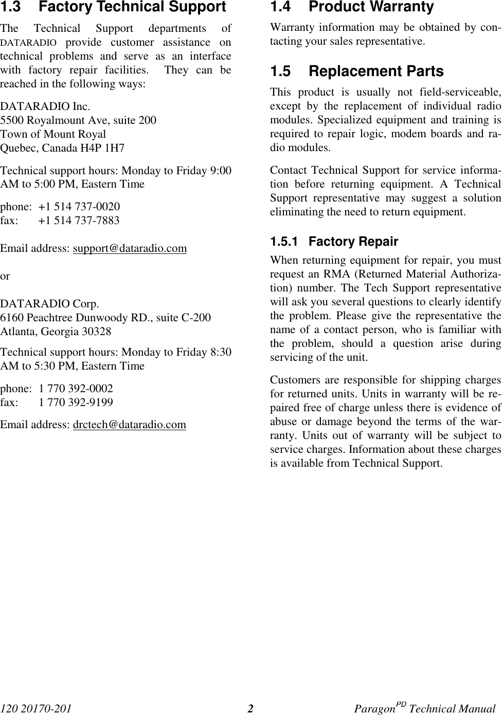
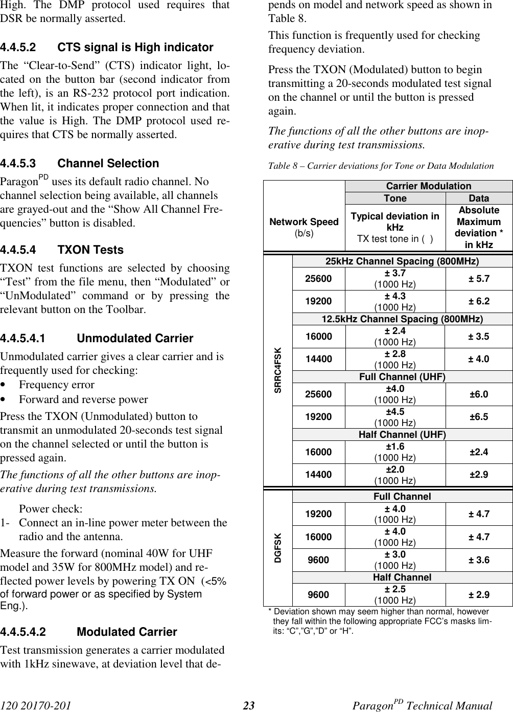
![120 20170-201 ParagonPD Technical Manual224.4.4.1 Banner FieldThis field displays a string made up of the serialnumber of the connected unit followed by thefirmwares used and their version number.Format is:[serial number]:firmware 1 name, its version #,firmware 2 name, its version #.The serial number portion uniquely identifiesthe unit. It is a variable length, maximum eight-character alphabetic string assigned at the timeof manufacture. It is identical to the serial num-ber printed on the label of the unit. This numbercannot be changed and is used as part of the on-air protocol.ParagonPD's firmwares reside in flash EPROMand are designed to allow field upgrades.When contacting your supplier, give the fullbanner string and the version of the WinRISused. You will find the version number by se-lecting the “Help” menu option, then “AboutWinRIS” command or pressing the “About”button on the Toolbar.The “Banner” field is blank prior to doing a"Get", "Get As" or "Put From".4.4.4.2 Comments1- Type comments directly in the “Comments”field. These can be text up to 24 characters.Use this field to enter user-convenient de-scription(s) (customer name, location,etc…).2- Press the button “Put Comments” to makethe entry permanent. This field may be leftblank.On subsequent “Get”, “Get As” or “Put From”,this field displays entered comments. If nocomment was entered, the field will remainblank.4.4.4.3 PasswordThe password feature is useful where two (ormore) fleets share the same radio channel. Mo-biles without the proper password would stillreceive the message but the contents would notbe intelligible.1- Type your password directly in the “Pass-word” field. It is a string of 32 hexadecimalcharacters (exactly).2- Press the button “Put Password” to make theentry permanent. This field may be leftblank.On subsequent “Get”, “Get As” or “Put From”,this field displays entered comments. If nocomment was entered, the field will remainblank.Password information is NOT retrieved andsaved to a file, along with the configuration.Clearing a Password is done by entering 32 zeros.The Dataradio supplied password algorithm isdesigned to thwart the casual observer only. Itprovides a limited form of data privacy. There-fore, if your security requirements are high,Dataradio urges you to use external encryptiontechnology such as Data Encryption Standard(DES) in the Host and Mobiles computers.4.4.5 Test FunctionsThe following WinRIS functions and buttonsare used to carry out testing or trouble-shootingon a connected unit:• DSR signal is High indicator• CTS signal is High indicator• TXON (Modulated)• TXON (Unmodulated)• Ping Address and Ping buttonWhile a button is in-use for test transmissions,all others are inoperative.4.4.5.1 DSR signal is High indicatorThe “Data Set Ready” (DSR) indicator light,located on the button bar (leftmost), is an RS-232 protocol port indication. When lit, it indi-cates proper connection and that the value is](https://usermanual.wiki/CalAmp-Wireless-Networks/BDD4T85-1.the-technical-manual-a-preliminary-version/User-Guide-148222-Page-30.png)
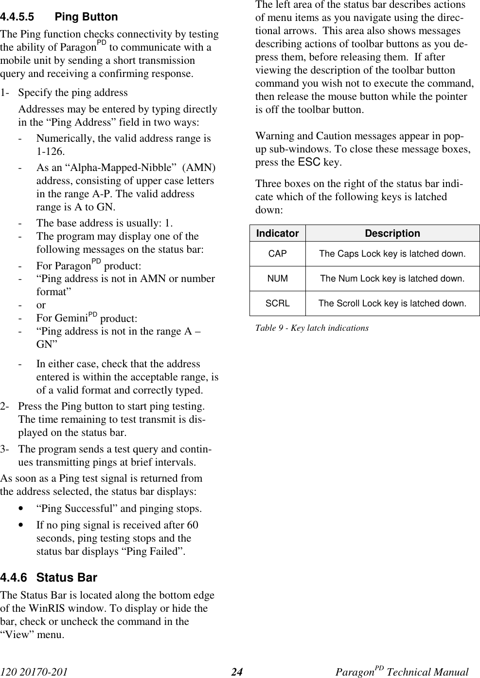


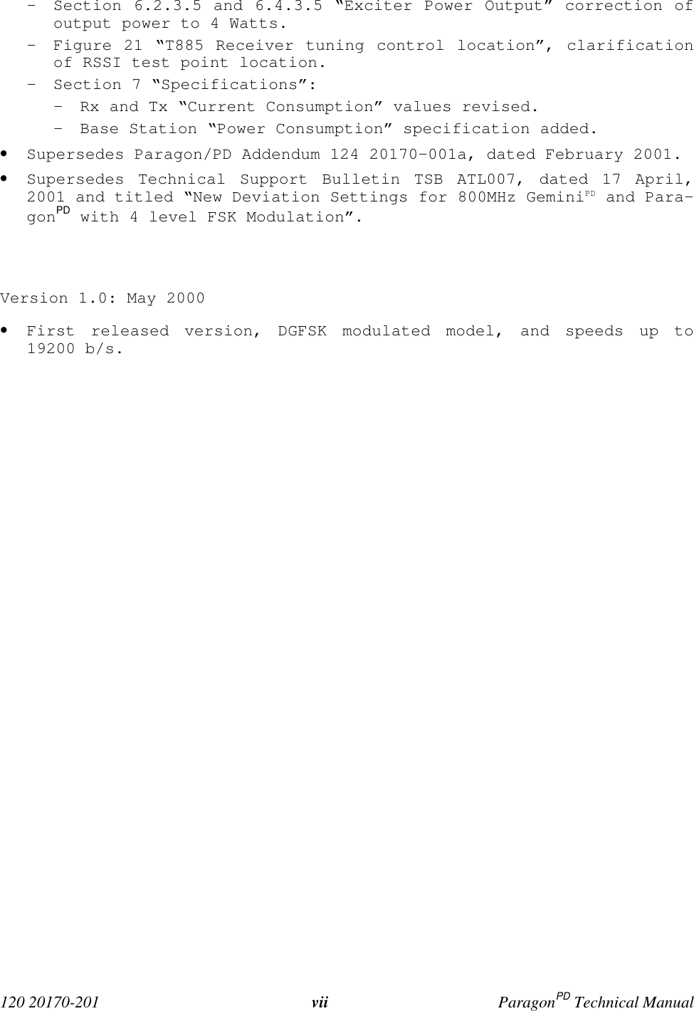
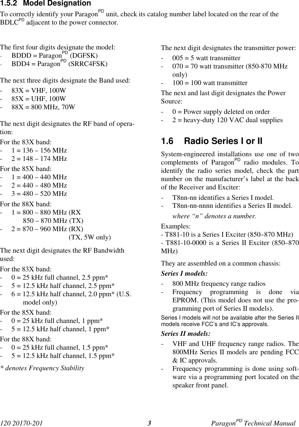
![120 20170-201 ParagonPD Technical Manual57Appendix 1 - ParagonPD Deviation adjust1. Using the WinRIS, press TX ON (Modulated) and record deviation level as read on the IFR.2. Using Windows Notepad, Edit the .bp2 file named with the corresponding BDLCPD serialnumber (e.g. abcd.bp2). “Save as” to another file name and keep it in case something goeswrong while changing a parameter.3. Locate the line labeled “Dev0 Par85=” and record the value beside the “=” sign. This is thecorresponding parameter value to the deviation read in step 1.4. Apply the following formula to determine the new parameter value to be set:(New Par85 value) = [(initial Par85 value) X (target deviation) / (deviation read)] + 25. Change the value in the file, “Save as” using the BDLCPD serial number file name.6. Run the WinRIS again and do a “Put From”. From the opened window, select the file thatyou just made the change to and then press “OK”7. Again, check deviation level while pressing TX ON (Modulated).• If the level is now correct, press Stationreset to make the change permanent.• Otherwise do step 5 again, changing the value entered in the file by 1 or 2 digit(s) upor down, fine-tuning directly the Par85 (DSP deviation) parameter. Do steps 6 and 7again to confirm acceptance.This last step may have to be repeated once or twice while varying the entered valueup or down. If unable to obtain the correct level after editing up and/or down by nomore than 2, contact System Engineering.](https://usermanual.wiki/CalAmp-Wireless-Networks/BDD4T85-1.the-technical-manual-a-preliminary-version/User-Guide-148222-Page-65.png)