Carlson Wireless Technologies RC2-CPE White Space Broadband Radio User Manual Revised Operator Manual
Carlson Wireless Technologies Inc White Space Broadband Radio Revised Operator Manual
Contents
- 1. Revised Operator Manual
- 2. Revised Operator Manual 1.74g
Revised Operator Manual
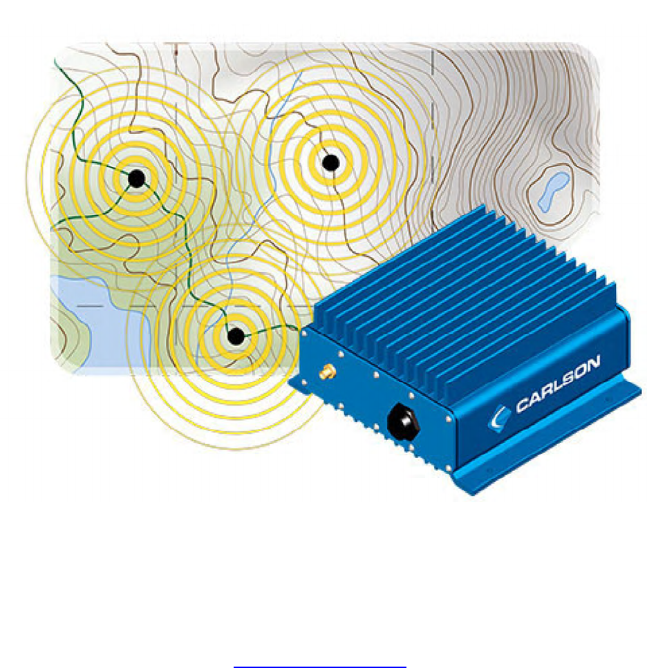
PRELIMINARY RELEASE
*** This is a confidential document. Do not distribute. ***
Revised December 2, 2013
RuralConnect
®
TV White Space Radio
Installation & User Guide
Carlson Wireless Technologies, Inc.
2700 Foster Avenue, Arcata, CA 95521
Tel: (707) 822-7000 Fax: (707) 822-7010
www.CarlsonWireless.com

PRELIMINARY RELEASE
*** This is a confidential document. Do not distribute. ***
Trademarks
RuralConnect® and the RuralConnect® logo are registered trademarks of Carlson Wireless
Technologies, Inc. Windows® is a registered trademark of the Microsoft Corporation in the
United States and other countries.
Copyright
Copyright© 2013 Carlson Wireless Technologies, Inc. All Rights Reserved. No person may
reproduce this manual without explicit permission from Carlson. The information contained in
this publication is the latest available, as of the date printed on each page. Carlson reserves the
right to make changes without notice. Current revisions are available upon request.
Carlson Headquarters: 2700 Foster Avenue, Arcata, CA 95521 USA
Sales Inquiries and Application Support
Please contact the Carlson Sales Department for sales and/or application inquiries. Purchasers
of Carlson products are required to make their own evaluations of product suitability for their
specific application(s). Carlson’s obligations regarding the use and/or application of our products
and/or the use of this manual are limited to the terms set forth in the Standard Terms and
Conditions of Sale for a delivered product.
Technical Support
Training and support are only available for products purchased directly from Carlson; the
purchaser is responsible for technical assistance for all other system components. Carlson
Support is available from 7:30 AM to 4:30 PM Pacific Standard Time, excluding weekends and
holidays.
Tel: +1 (707) 822-7000
Email: support@carlsonwireless.com
Repair and Return
Carlson will replace or repair this product within one year from the date of shipment if it does not
meet published specifications, or if it fails while in service due to a manufacturer’s defect. You
must obtain a return merchandise authorization (RMA) prior to returning equipment to Carlson.
You can request an RMA on our web site at http://www.carlsonwireless.com/support/rma-
request.html.
Safety Warnings
In order to prevent personal injury, property damage, and/or equipment failure, it is essential that
the installer employ appropriate safety measures when testing, installing, or maintaining
RuralConnect® equipment. You are required to review all safety warnings in this manual prior to
testing, installing, and/or maintaining the system.
Qualified Personnel
Professionally trained service technicians are the only personnel qualified to perform the testing
and/or configuration steps outlined in this manual. Technicians are responsible for adhering to
all applicable safety regulations and industry-standard best practices. Carlson does not
Page | 2

PRELIMINARY RELEASE
*** This is a confidential document. Do not distribute. ***
authorize non-qualified personnel to work on equipment without the direct supervision of a
professionally trained service technician.
Proper Handling and Grounding
The electronic components of the RuralConnect® equipment are sensitive to electrostatic
discharge (ESD). In order to prevent potential warranty voiding damage, you must use an
adequately grounded anti-static wrist strap when handling the equipment. It is also important to
avoid the use of conductive tools. In order to prevent electric shock, always disconnect the
remote power source and all cables from the system prior to disconnecting the grounding
connection.
Installation
You must never perform any installation work on a tower, mast, or rooftop during lightning
storms or other inclement weather. Dangerous work of this nature could result in serious injury
and/or death. It is important to adhere to all of the applicable local, state, and federal regulations
pertaining to safety equipment and tower climbing practices.
RF Hazards
Per FCC regulations, RuralConnect® systems must be installed in a manner that ensures a
minimum of 40 centimeters (15.7 inches) separation between the antenna and any person.
Failure to do so could result in a fine and/or personal injury.
RF Exposure
The radio described in this manual transmits RF energy. The concentrated energy from the
antenna may pose a health hazard. All antennas used with this radio must be installed to
provide a minimum separation from all persons of 40 cm (15.7 inches). The above separation
distance must be maintained at all times. More information can be obtained from the FCC at the
following website:
http://www.fcc.gov/Bureaus/Engineering_Technology/Documents/bulletins/oet65/oet65.pdf
Regulatory Compliance Information
Per Part 15 of the FCC regulations, the RuralConnect® operates within the specified limits of a
Class A digital device. Those limits ensure reasonable protection from harmful interference
when operating the equipment in a commercial setting. This system generates, utilizes, and may
radiate radio frequency energy. Incorrect installation and/or equipment use inconsistent with the
instructions in the manual may result in harmful interference to radio communications. Operation
of this equipment in a residential area may cause harmful interference in which case the user
will be required to correct the interference at his or her expense.
RuralConnect® operation is subject to the following two conditions:
1. This device may not cause harmful interference.
2. This device must accept any interference received, including interference that may
cause undesired operation.
Page | 3
PRELIMINARY RELEASE
*** This is a confidential document. Do not distribute. ***
Additional Information on TV Band Interference Protection
This equipment has been tested and found to comply with the rules for TV band devices,
pursuant to Part 15 of the FCC Rules. These rules are designed to provide reasonable
protection against harmful interference. This equipment generates, uses and can radiate radio
frequency energy and, if not installed and used in accordance with the instructions, may cause
harmful interference to radio communications. If this equipment does cause harmful interference
to radio or television reception, which can be determined by turning the equipment off and on,
the user is encouraged to try to correct the interference by one or more of the following
measures:
1. Reorient or relocate the receiving antenna.
2. Increase the separation between the equipment and receiver.
3. Connect the equipment into an outlet on a circuit different from that to which the
receiver is connected.
4. Consult the manufacturer, dealer or an experienced radio/ TV technician for help.
FCC Registration Requirements
Per FCC regulations; you must register your RuralConnect® system with a certified spectrum
database (such as Spectrum Bridge) prior to performing any bench tests and/or completing the
final installation. You will need a Special Temporary Authority (STA) if you are using uncertified
experimental hardware or software.
Compliance and US Regulatory Information
FCC Identifier OPA-RC2
FCC Part 15H 470-608 MHz (TV channels 14-36)
FCC Part 15H 614-698 MHz (TV channels 38-51)
Emission designators
6 MHz channels 6M00F1D
Declaration of Conformity
Manufacturer’s Name: Carlson Wireless Technologies Inc.
Manufacturer’s Address: 2700 Foster Ave, Arcata, CA 95521 USA
Declares that the product:
Product Name: RuralConnect®
Conforms to the following standard(s) or other normative document(s):
EMC:
FCC Part 15.247 subpart H
Page | 4
PRELIMINARY RELEASE
*** This is a confidential document. Do not distribute. ***
Table of Contents
1.1. Scope of Manual.............................................................................................................7
1.2. Overview.........................................................................................................................7
2.1. Proper Handling..............................................................................................................7
2.2. Grounding.......................................................................................................................8
2.3. Lightning Protection........................................................................................................8
2.4. Cable Recommendations ...............................................................................................8
2.4.1. RF Cables ...............................................................................................................9
2.4.2. Data Cables.............................................................................................................9
2.5. Recommended Tools .....................................................................................................9
2.6. Before Arrival................................................................................................................10
2.7. Unpacking.....................................................................................................................10
2.8. Spectrum Database Registration..................................................................................10
2.9. Bench Testing...............................................................................................................10
2.9.1. Test Cable Set.......................................................................................................11
2.9.2. Setting up the Bench .............................................................................................11
2.9.3. Getting Started on the OMC ..................................................................................12
2.9.4. Verifying Geographical Coordinates......................................................................13
2.9.5. Verifying Cell Control.............................................................................................14
2.10. RF Testing with RadioTest........................................................................................15
2.10.1. Minimum System Requirements........................................................................15
2.10.2. Download the RadioTest Software ....................................................................15
3.1. Field Installation............................................................................................................15
3.1.1. Professional Installers ...........................................................................................15
3.1.2. Antenna height and RF exposure warnings ..........................................................15
3.1.3. Installing RuralConnect® CPE units......................................................................15
3.1.4. Installing RuralConnect® Basestation units ..........................................................16
4.1. Basestation...................................................................................................................16
4.2. CPE (Customer Premise Equipment) ...........................................................................17
5.1. Registration ..................................................................................................................18
5.2. Signing into the OMC....................................................................................................18
5.3. Home Page...................................................................................................................19
5.4. Operations Panel..........................................................................................................19
5.4.1. System Health .......................................................................................................19
5.4.2. Network Map .........................................................................................................19
5.4.3. Cells ......................................................................................................................20
5.5. Stations.........................................................................................................................20
5.6. Cell Control...................................................................................................................21
5.6.1. Modulation Modes .................................................................................................21
5.7. Station Properties .........................................................................................................22
5.7.1. Basestation Details................................................................................................22
5.7.2. CPE Properties/Details..........................................................................................24
6.1. Specifications ...............................................................................................................26
6.2. Warranty .......................................................................................................................27
6.3. Acronyms/Abbreviations...............................................................................................28
6.4. Glossary .......................................................................................................................28
6.5. Useful URLs .................................................................................................................30
Page | 5
PRELIMINARY RELEASE
*** This is a confidential document. Do not distribute. ***
6.6. Manual Revision Notes.................................................................................................31
Table of Figures
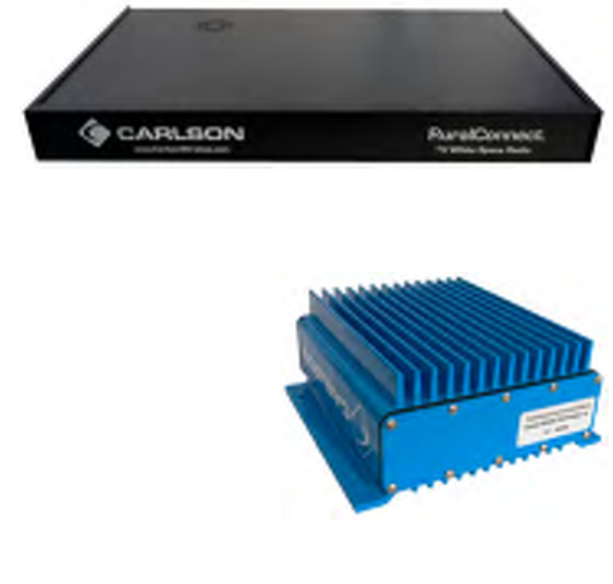
Figure 1: RuralConnect® Base Unit..............................................................................................7
Figure 2: RuralConnect® CPE Unit...............................................................................................7
Figure 3: Bench-Testing Cable Set .............................................................................................11
Figure 4: Basestation with Ethernet cable connected .................................................................11
Figure 5: Basestation Connections .............................................................................................11
Figure 6: POE Injector Connections............................................................................................11
Figure 7: OMC Sign-In ................................................................................................................12
Figure 8: OMC Shortcut Tabs .....................................................................................................12
Figure 9: Station Listing ..............................................................................................................12
Figure 10: Individual Basestation Detail......................................................................................12
Figure 11: Messages Listing .......................................................................................................13
Figure 12: Properties Tab ...........................................................................................................13
Figure 13: Latitude/Longitude Settings .......................................................................................13
Figure 14: Cell Control Tab .........................................................................................................14
Figure 15: Cell Control - Basestation & CPEs.............................................................................14
Figure 16: CPE pole mount detail ...............................................................................................16
Figure 17: Carlson Basestation...................................................................................................16
Figure 18: Carlson Basestation Rear Panel................................................................................17
Figure 19: Carlson Basestation Ethernet Cable Connections.....................................................17
Figure 20: RuralConnect® CPE..................................................................................................17
Figure 21: RuralConnect® CPE Bottom......................................................................................18
Figure 22: OMC Sign-In Screen..................................................................................................18
Figure 23: Home Page - Text Hyperlinks ....................................................................................19
Figure 24: Messages ..................................................................................................................19
Figure 25: Network Map..............................................................................................................19
Figure 26: Filtering Choices ........................................................................................................20
Figure 27: Expanded "Cell" List ..................................................................................................20
Figure 28: Stations Display .........................................................................................................20
Figure 29: Cell Control Display ...................................................................................................21
Figure 30: Modulation Settings ...................................................................................................21
Figure 31: Station Links ..............................................................................................................22
Figure 32: Basestation Details ....................................................................................................22
Figure 33: Channel Allocation.....................................................................................................23
Figure 34: Interface Date/Time Stamps ......................................................................................23
Figure 35: Base Registration Details...........................................................................................24
Figure 37: CPE Details ...............................................................................................................24
Figure 39: CPE Channel Allocations...........................................................................................25
Figure 40: Interfaces Last Reported............................................................................................25
Figure 41: SNR History Graph ....................................................................................................26
Page | 6
PRELIMINARY RELEASE
*** This is a confidential document. Do not distribute. ***
poor
1. Introduction
1.1. Scope of Manual
The purpose of this manual is to provide professional planning and installation personnel with
the appropriate information and procedures required to install and operate the RuralConnect®
TV White Space Broadband Radio and accessory equipment. In order to avoid harm to persons
or damage to the product, please ensure that you have read and understand the safety,
unpacking, and installation sections before proceeding.
1.2. Overview
The RuralConnect® TV White Space
Broadband Radio is designed to utilize
“white space” spectrum in the 470–608
MHz (TV channels 14–36) and 614–698
MHz (TV channels 38–51) frequencies
in order to provide reliable, high speed
broadband for applications where
traditional microwave solutions won’t provide adequate RF
performance.
The system uses state of the art Single Carrier Frequency
Domain Equalization (SC-FDE) to provide protection against
signal fading caused by multipath interference (phase-shifting)
while offering a robust clean transmit spectrum. Reflections
from trees, buildings and hills are inevitable for long range
wireless links. These reflections arrive at slightly different
times, causing deep fading across the channels used by white
space systems. Without equalization, this fading causes
performance; even for links between devices that are
theoretically in range. SC-FDE allows more flexible installations
where obstructions and foliage are known factors. Combined with a proprietary adaptive
equalization system, SC-FDE allows the system to correct for multipath fading. This ensures
reliable connections even in mountainous, forested, and/or built-up areas where strong signal
reflections are common.
Figure 2: RuralConnect® CPE Unit
In the U.S., the RuralConnect® is only available with a 6 MHz channel bandwidth. The system is
fully compliant with FCC Part 15H regulations.
Our international models ensure worldwide compatibility, regardless of the TV broadcast
technology in use. International users must ensure compliance with their regulatory authorities.
For export only, international models are available in both 6 MHz and 8 MHz versions.
2. Pre-test and System Planning
2.1. Proper Handling
You must follow precautionary measures when handling RuralConnect® devices. Improper
handling of your equipment may cause damage and void your warranty. The electronic
Page | 7
PRELIMINARY RELEASE
*** This is a confidential document. Do not distribute. ***
components of the RuralConnect® equipment are sensitive to electrostatic discharge (ESD).
Use adequate ESD protection, such as an anti-static wrist strap, whenever handling the
equipment. It is also important to avoid the use of conductive tools.
2.2. Grounding
A ground is a low impedance electrical connection to the earth utilized for energy dissipation.
Grounding the RuralConnect® is very important for safety reasons, as well as protecting the
system from damage due to lightning and/or static charge build up. Since lightning strikes and
surges are high-current and high-frequency events; short, straight ground wires (not coiled or
looped) must be used. Choose the largest diameter ground wire your ground connectors will
accept for good electrical conductivity. We recommended a #8 gauge copper wire or larger.
Utility company grounds, grounding rods, well casings, and cold water pipes constructed of
continuous metal are strongly recommended. A note of caution: sometimes repaired and/or
extended metal cold-water pipes include PVC sections hidden behind drywall. PVC will disrupt
conductivity and render the pipe unacceptable as a ground. Conductivity is often poor in desert
areas, so multiple ground rods may be required (preferably bonded together to make a suitable
connection). The impedance of your grounding should never exceed 5 Ohms. Carlson
recommends maintaining a ground with less than 3 Ohms. Undesirable grounds include, but are
not limited to, sprinkler pipes, PVC pipes, conduit, and buried wire. Never use an unverified
ground.
In order to prevent electric shock, always disconnect the remote power source and all cables
from the system prior to removing the grounding connection.
2.3. Lightning Protection
Poorly grounded lightning protection is the same as having no protection at all!
Lightning is one of the most dangerous, yet most common, natural hazards for a RuralConnect®
system. It is absolutely essential to install and maintain adequate lightning protection for your
equipment. Verified ground connections are imperative for lightning protection to work correctly.
Primary lightning protection is located outside the enclosure. Install primary lightning protection
with a good ground on all RF and/or data connections that have even a moderate outdoor line
build-out. Best practices dictate all lines entering or exiting a building need protection. You must
use protection on both ends of the cables between buildings! Contact your sales representative
for detailed specifications and usage information for the primary lightning protection solutions
available from Carlson.
In areas with frequent lighting activity, augmenting the client station install with a nearby
lightning rod is strongly recommended. Lightning can be unpredictably strike, might miss the
antenna mast altogether, and make contact with underlying wiring/cabling instead. Lightning
discharges into the lowest impedance path to ground, i.e. earth. In many cases this will be the
master ground in the primary AC panel, unless nearby grounding is installed.
2.4. Cable Recommendations
Use of proper high-quality cabling is important to ensure the best performance for your
RuralConnect® system. Carlson extensively researched and tested cabling before selecting
those offered for RuralConnect® customers. It is recommended that you use only Carlson
approved cables. Discuss your cabling options with your Carlson Sales Representative.
Page | 8

PRELIMINARY RELEASE
*** This is a confidential document. Do not distribute. ***
2.4.1. RF Cables
Carlson carries professional-grade RF coax cables that provide greater durability and less
attenuation/loss than those readily available. We offer and recommend well-insulated 75-Ohm
broadband coaxial cable with gas-injected foam polyethylene insulation. For short jumper
connections, use 18 AWG RG-6/U cables with a solid .040” bare copper conductor. For longer
runs, use 14 AWG RG-11 cables with a .064” bare copper conductor.
Only use cables with 100% solid copper center conductors. Lower-quality copper-clad
conductors have decreased performance and can lead to failures.
75-Ohm cabling used for RuralConnect® installation cannot exceed 150-feet (45.72 meters).
Terminate all coax cables with weather-sealed 75-Ohm F-type compression connectors with
PVC jackets. Do not use crimp-type connectors.
Avoid cable bends as much as possible; do not put more than a 90-degree bend in any cable
run.
2.4.2. Data Cables
Network performance is greatly affected by the quality of the data cabling used. Carlson carries
and recommends shielded, grounded, outdoor Category-5 or higher twisted pair cable.
2.5. Recommended Tools
These are the tools needed to set up a RuralConnect® system. Make sure you have them
handy to ensure a seamless installation.
ESD gear
Wrench set (Standard)
Socket set (Standard)
Screwdriver set (Phillips and Standard)
Multimeter/multitester
Wire cutters
Wire strippers
Vapor wrap
Electrical tape
You will need an IBM PC-compatible computer (or equivalent virtual machine) equipped with the
following:
Microsoft Windows 7 or greater
Microsoft .NET Framework 4.5
At least 512 Megabytes (MB) of RAM
Keyboard and mouse (or other compatible pointing device)
Display adapter and monitor (1024x768 or higher resolution)
100/1000 Mbps Ethernet network adapter
Pre-Installation
Page | 9
PRELIMINARY RELEASE
*** This is a confidential document. Do not distribute. ***
2.6. Before Arrival
Users operate the RuralConnect® system from the Online Management Center, or OMC. After
placing your order, and prior to receiving the equipment, you will need to have a registered OMC
user account.
If you do not have an OMC account, visit http://omc.neul.com and click “register a new account”.
You may wish to have multiple accounts for your employees. Send your new username(s) to
Carlson Support, at support@carlsonwireless.com.
Carlson will assign each account to a user group for your company, along with your desired set
of permissions for each user/group.
Please note: You will not be able to properly test or configure your RuralConnect radios until you
have a registered OMC account.
2.7. Unpacking
Before opening package(s), inspect them and report any damage to the shipping carrier. Per
shipping insurance agreements, the shipping carrier is responsible for any damage to the
equipment. Unpack and compare the contents against the packing slip and inspect everything
for damage. Report any missing or damaged components to your Carlson Customer Service
Representative.
2.8. Spectrum Database Registration
Unless registered with a Certified TVWS Database Administrator, it is necessary to apply for a
Special Temporary Authority (STA) before conducting any over-the-air testing. If the fixed TVBD
is moved to another location or if its stored coordinates become altered, the operator shall re-
establish the device’s registration with the database based on the device’s new coordinates.
Follow this link to apply for an STA:
https://apps.fcc.gov/oetcf/els/forms/STANotificationPage.cfm
Note: Prior to powering your radios and conducting tests, you must have a list/map of allowable
channels specific to the Basestation and CPE locations. Use the online Spectrum Bridge Show
My White Spaces tool to get a list of channel available in your areas.
2.9. Bench Testing
Prior to deploying your
RuralConnect® units, it is
important to become familiar
with their operation and
verify their functionality. The
following section provides
detailed instructions
required for a complete
bench test. Please contact
Carlson Support if you
require further information
and/or assistance with that
process.
Page | 10
PRELIMINARY RELEASE
*** This is a confidential document. Do not distribute. ***
Warning: Never power up a unit without proper cabling and attenuation. You must have at least
60 dB of attenuation between RuralConnect® units. Failure to do so could result in system
damage that may void the warranty.
2.9.1. Test Cable Set
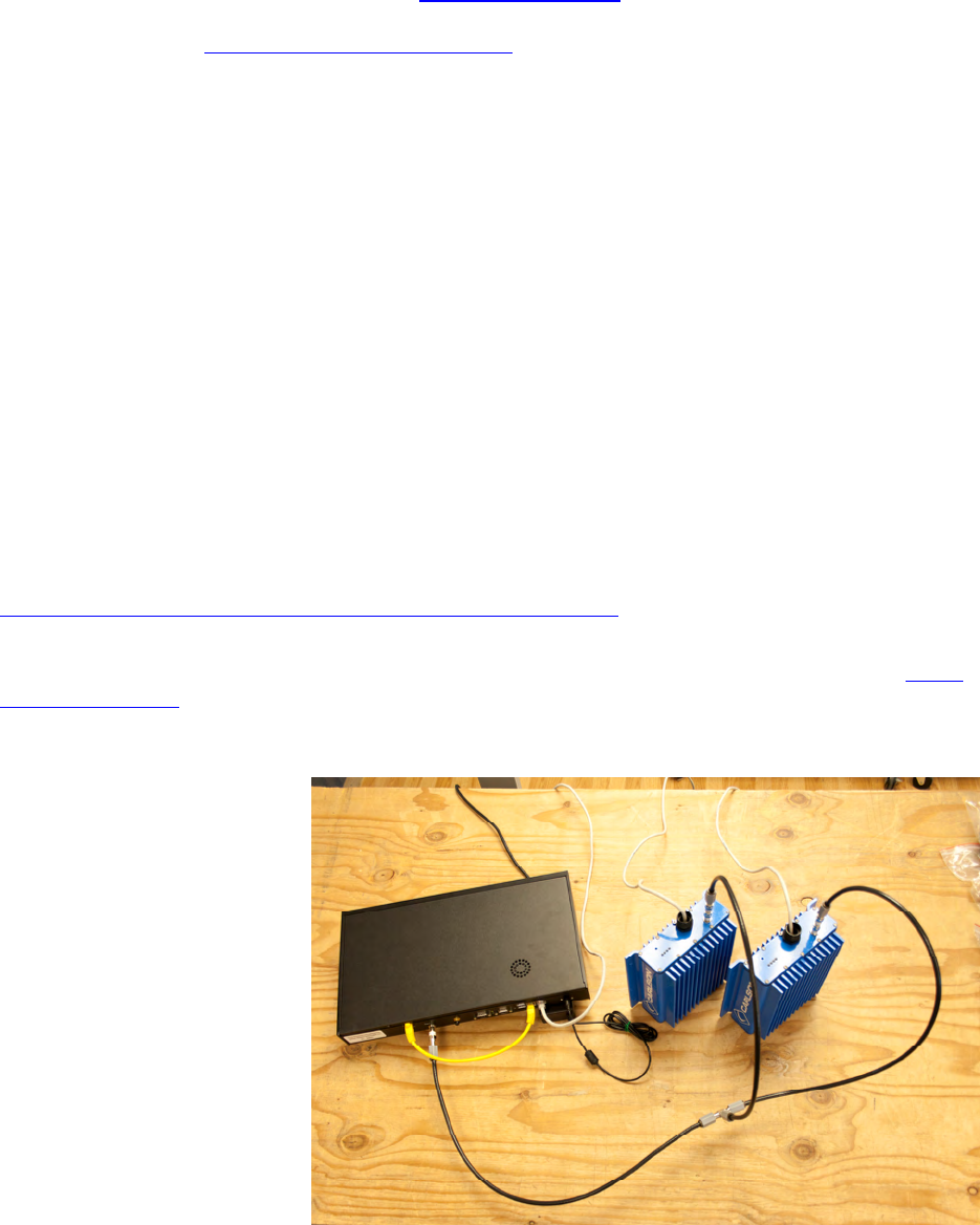
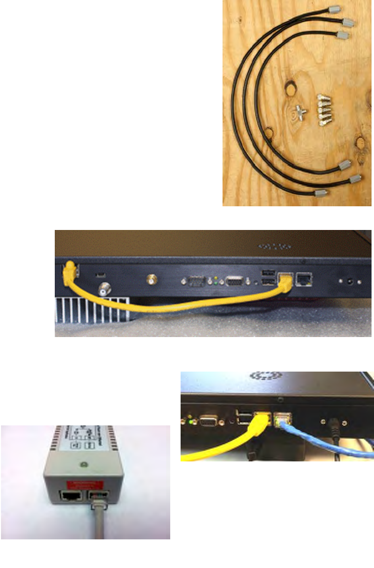
The bench-testing cable set (“RC-TECH-KIT”) will allow you to
bench test a Basestation with two CPEs. Connect the units with
the supplied cables and connectors. This consists of a set of
coax jumper cables (one for each unit), an F-type splitter and
five 19 dB attenuators (one for the Basestation, two for each
CPE).
2.9.2. Setting up the Bench
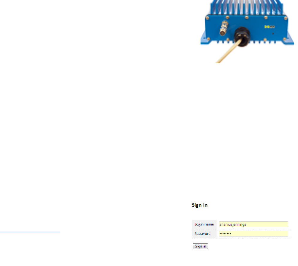
Use the supplied yellow Ethernet patch cable to connect the
radio’s Ethernet port to the Base controller board Ethernet port
as shown in Figure 4.
For Internet access, connect the Basestation unit to a DHCP-
enabled network via a standard Ethernet cable. Plug the
Ethernet cable into the Ethernet port nearest to the power jack. Figure 3: Bench-Testing Cable Set
Note the blue cable in
tation
Ethernet
Figure 5 as an example:
Connect the Bases
unit’s power supply to its
barrel-type power jack, as
shown in photo.
Using a standard
cable (not supplied),
connect each CPE unit to
the “Out” connection of a
POE injector as shown
below:
Figure 4: Basestation with Ethernet cable connected
Connect each unit to a power source.
Wait approximately 3-5 minutes for the system to
initialize.
Figure 5: Basestation Connections
Figure 6: POE Injector Connections
Page | 11
PRELIMINARY RELEASE
*** This is a confidential document. Do not distribute. ***
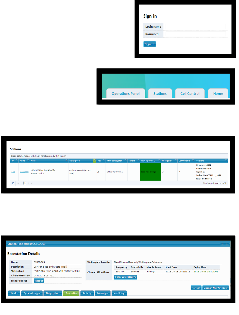
2.9.3. Getting Started on the OMC
You will use the Neul/Carlson Operation &
Management Center to test and operate your
RuralConnect® radios. Open a web browser and
browse to http://omc.neul.com.
Enter your OMC user name and password. You
should have an OMC account created by Carlson.
The username will match your Carlson Customer
ID. If you do not have a user
account, you will need to create
and submit a request to have your
radios assigned to your new
Figure 7: OMC Sign-In
one
a
e page, click the
“Stations” tab.
for your Basestation (i.e., "CSB00123"), which will take you to the
“Basestation Details” page.
ccount.
Note: database requests take a
minimum of 24 hours to process.
On the Welcom
Figure 8: OMC Shortcut Tabs
Figure 9: Station Listing
Note: If you do not have any stations listed, contact Carlson Support.
Click on the named hyperlink
Figure 10: Individual Basestation Detail
Page | 12
PRELIMINARY RELEASE
*** This is a confidential document. Do not distribute. ***
by either
installer.
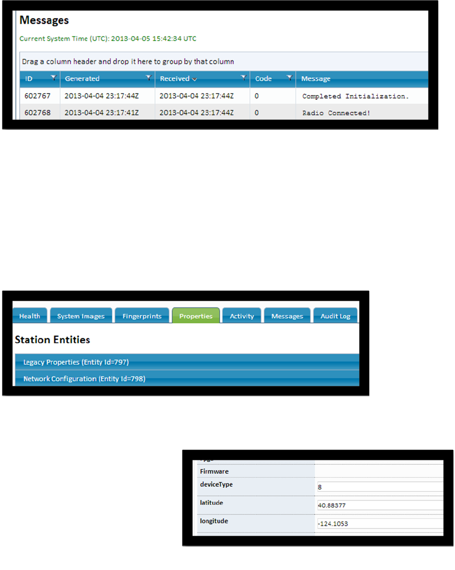
On the “Basestation Details” page, click the “Messages” tab.
The last few messages should include “Radio Connected!” and “Completed Initialization”.
Figure 11: Messages Listing
Verify that the message dates and times are correct for system initialization.
If “Radio Connected!” and “Completed Initialization” messages are not displayed, then
troubleshoot your Internet connection and/or wait another 3-5 minutes. If the system still fails to
initialize, contact Carlson Support.
2.9.4. Verifying Geographical Coordinates
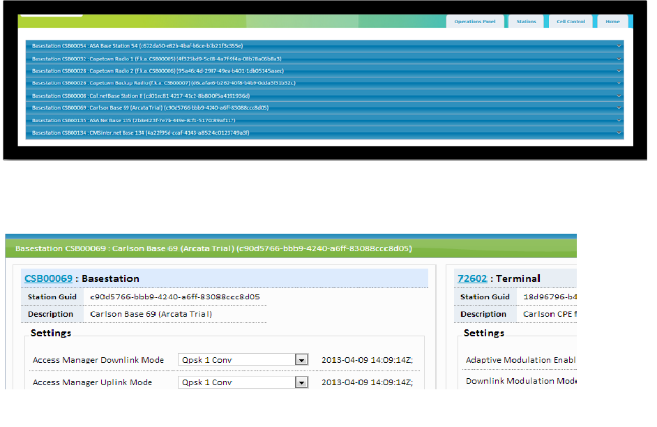
Click the “Properties” tab.
Under “Station Entities”, select the “Legacy Properties” drop-down tab.
Figure 12: Properties Tab
Scroll down to view latitude and
longitude information.
Verify the latitude and longitude
information is correct for the
Basestation. Geographic
coordinates shall be determined to
an accuracy of ±50 meters
an incorporated geo-location
capability or a professional Figure 13: Latitude/Longitude Settings
Page | 13
PRELIMINARY RELEASE
*** This is a confidential document. Do not distribute. ***
on and/or wait
assistance.
OE injector
ection
t
son Support.
Turn to Page 18 for more information about the Operation and Management Center (OMC).
If your find incorrect latitude and longitude information, contact Carlson Support or your
spectrum database manager for correction.
Close the “Basestation Details” window.
2.9.5. Verifying Cell Control
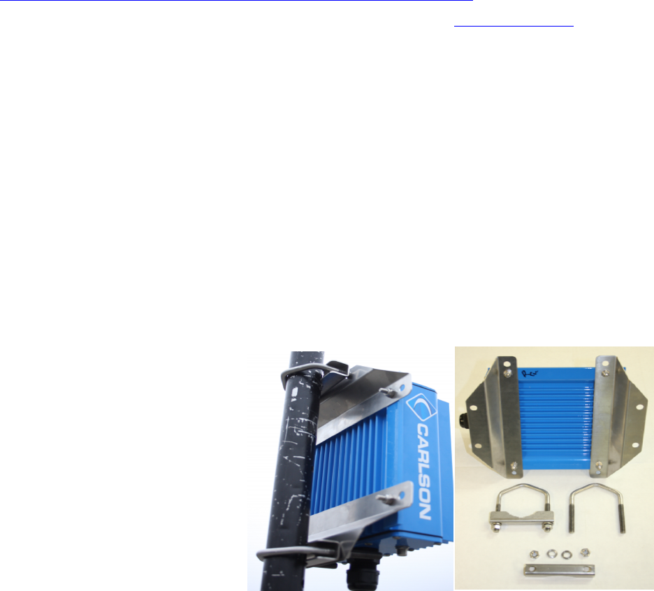
At the top of the page, click the “Cell Control” tab.
Select the tab shown for your Basestation. Both the Basestation and its active CPEs will appear.
Figure 14: Cell Control Tab
Figure 15: Cell Control - Basestation & CPEs
If the Basestation and CPEs do not appear, troubleshoot the Internet connecti
another 3-5 minutes. If they fail to appear, contact Carlson Support for technical
Using a standard Ethernet cable (not supplied), connect a PC to the “IN” port of the P
connected to the first CPE.
Open a web browser and navigate to a webpage of your choice. A successful conn
verifies the operational status of the link.
ur Internet connection and/or waiIf you are unable to browse to a website, troubleshoot yo
another 3-5 minutes. If you need assistance, contact Carl
Repeat link verification steps for remaining CPE unit(s).
Once you have verified the operational status of every unit, congratulations! You have
completed the first step in testing your new RuralConnect system.
Page | 14
PRELIMINARY RELEASE
*** This is a confidential document. Do not distribute. ***
2.10. RF Testing with RadioTest
Either on the bench or in the field, you can use the RadioTest software to test the RF
performance of the radio. This software will provide you with accurate measurement of the
signal-to-noise ratio (SNR), bit error rate (BER) and more.
2.10.1. Minimum System Requirements
Use of the RadioTest software requires two IBM-compatible PCs with the following:
1 GHz processor
512 MB of RAM
Microsoft Windows 7 operating system
Microsoft .NET Framework 4.5
An Ethernet patch cable
2.10.2. Download the RadioTest Software
You may obtain the RadioTest software from our website by following the link below:
http://www.carlsonwireless.com/applications/RadioTest/RadioTest.zip
This section of the manual is under development. Visit the Carlson Online Help Desk if you have
any questions.
3. Installation
3.1. Field Installation
3.1.1. Professional Installers
RuralConnect® radios can only be installed by professionally trained personnel.
3.1.2. Antenna height and RF exposure warnings
RuralConnect® installations must adhere to all local, state, and federal regulations. Failure to
follow those guidelines could result in costly fines, damage to the equipment, and/or inadequate
RF protection for end users. Per FCC regulations; antennas used with fixed TV Band devices
may not be more than 30 meters above ground level, or 250 meters above average terrain. All
persons are required to maintain at least a 40 cm distance from the device; additional hardware
may be required to ensure that separation. All regulatory compliance requirements related to the
installation and operation of
RuralConnect® devices are the
sole responsibility of the operator.
3.1.3. Installing
RuralConnect® CPE
units
Most CPE installs will use pole
mounts for mounting
RuralConnect® Tower Top units
Page | 15
PRELIMINARY RELEASE
*** This is a confidential document. Do not distribute. ***
directly below the antenna (see Figure 16).
The pole mount clamp is reversible for a wide variety of mast sizes. Please note that the
articulating bolts need to be tighter than you would expect in order to retain their position.
This section of the manual is under
development. Visit the Carlson
Online Help Desk if you have any
questions.
Figure 16: CPE pole mount detail
3.1.4. Installing RuralConnect® Basestation units
Rack-mounted Basestations require 3U of 19" rack space.
This section of the manual is under development. Visit the Carlson Online Help Desk if you have
any questions.
4. Configuration and Setup
This section of the manual is under development. Visit the Carlson Online Help Desk if you have
any questions.
4.1. Basestation
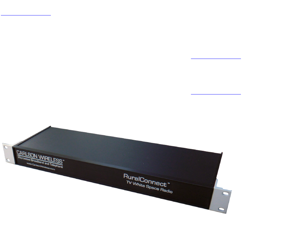
The Basestation is a 19” rack mountable device that will normally be installed in a weatherproof
cabinet at or close to the mounting point for its external antenna. Suitable antennas are
available from Carlson.
Figure 17: Carlson Basestation
The Basestation connects to the internet via a standard Ethernet port, where it automatically
obtains an IP address from a DHCP server. It encodes data from the Ethernet connection for
transmission to one or more CPE units. It decodes transmissions from the CPEs and sends
these to the internet.
Carlson designers have deliberately limited the number of physical controls on the Basestation.
All of the control, configuration and management options of the Basestation are handled via the
cloud-based OMC interface.
Page | 16
PRELIMINARY RELEASE
*** This is a confidential document. Do not distribute. ***
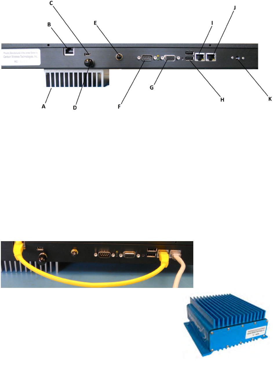
Figure 18: Carlson Basestation Rear Panel
The rear panel of the Basestation has the following ports:
A. Heat Sink
B. Radio Board Ethernet Port*
C. Mini USB Diagnostic Port (Unused)
D. RF Port
E. GPS Antenna Port
F. Serial Port (Unused)
G. VGA Port (Unused)
H. USB Ports (Unused)
I. Base Controller Board Ethernet Port*
J. Ethernet Port (Internet in/out)
K. AC Power
*Base Controller Board and Radio Card Connected via Ethernet Cable
4.2. CPE (Customer Premise Equipment)
The CPE, also call "Client Station", is installed at the subscriber’s premises. RuralConnect®
CPEs use external antennas that operate over the entire UHF band; from 470 MHz to 698 MHz.
Speak to your Carlson Sales Representative about the antenna selection available.
ses. RuralConnect®
CPEs use external antennas that operate over the entire UHF band; from 470 MHz to 698 MHz.
Speak to your Carlson Sales Representative about the antenna selection available.
Figure 19: Carlson Basestation Ethernet Cable Connections
Figure 20: RuralConnect® CPE
Page | 17
PRELIMINARY RELEASE
*** This is a confidential document. Do not distribute. ***
CPEs connect to a Basestation via a UHF radio signal. Due to
the unique propagation characteristics of signals in the UHF
band, good connections are generally possible even if there is a
non-line-of-sight path to the Basestation. Once a link to the
Basestation is established, CPEs provide network access via a
standard Ethernet connection.
The bottom plate of the CPE has an RF port, Ethernet port and
four (4) RSSI LEDs.
Figure 21: RuralConnect® CPE Bottom
5. Operation and Management Center (OMC)
5.1. Registration
The Carlson/Neul Operation and Management Center (OMC) provides a cloud level view of all
RuralConnect® devices registered under a given user name. You will use this online tool to
manage your RuralConnect® network.
The RuralConnect® Basestation obtains and reports information to and from the OMC via the
Internet. Regardless of the RF status, the OMC pushes settings to the Basestation, and polls its
status. If the Basestation is offline during a configuration change, the OMC will apply those
changes upon re-establishing a connection to the Basestation.
This user guide will provide you with all the information you need to operate your
RuralConnect® system.
5.2. Signing into the OMC
Open your web browser and navigate to
http://omc.neul.com.
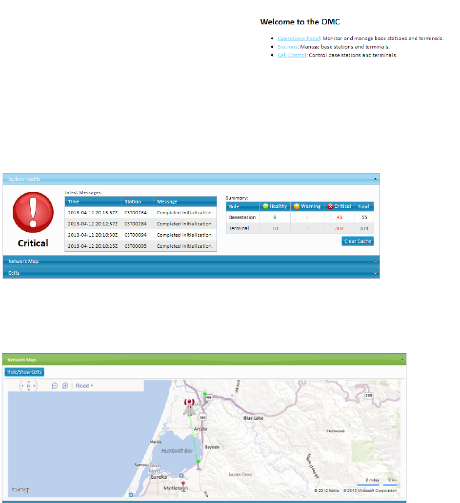
At the sign-in screen, enter your login name and password.
Press Enter or click the “Sign in” button.
Your account(s) should be setup ahead of time. If you do not
have an OMC account, click “Register a new account”. Enter a desired username and your
email address. You must then send your username to Carlson Support, who will send a
permissions request to allow access to your RuralConnect radios.
Figure 22: OMC Sign-In Screen
Note: database requests take a minimum of 24 hours to process.
If you do not remember your password, click “Retrieve forgotten login information”. You will
receive an email with a verification link to gain access to your account.
Page | 18
PRELIMINARY RELEASE
*** This is a confidential document. Do not distribute. ***
5.3. Home Page
After logging in, you will see the Home page, displaying bulleted text hyperlinks to help you
navigate to each section.
The OMC also has navigation tabs, available from
any page. While browsing around the OMC, the
“Home” tab will bring you back to this page.
5.4. Operations Panel
To access the Operations Panel, click on its link.
This section of the OMC provides you with a high-
level overview of your entire RuralConnect®
network.
Figure 23: Home Page - Text Hyperlinks
5.4.1. System Health
The first drop-down tab shown is “System Health”. This section displays the most recent
messages and a status summary of your entire system.
Figure 24: Messages
5.4.2. Network Map
Click on the next drop-down tab, “Network Map”. This displays all your radios, based on the
roles and coordinates of each.
Figure 25: Network Map
The map displays Basestations with tower-like figures, and CPEs as smaller beacon-like figures.
Page | 19
PRELIMINARY RELEASE
*** This is a confidential document. Do not distribute. ***
5.4.3. Cells
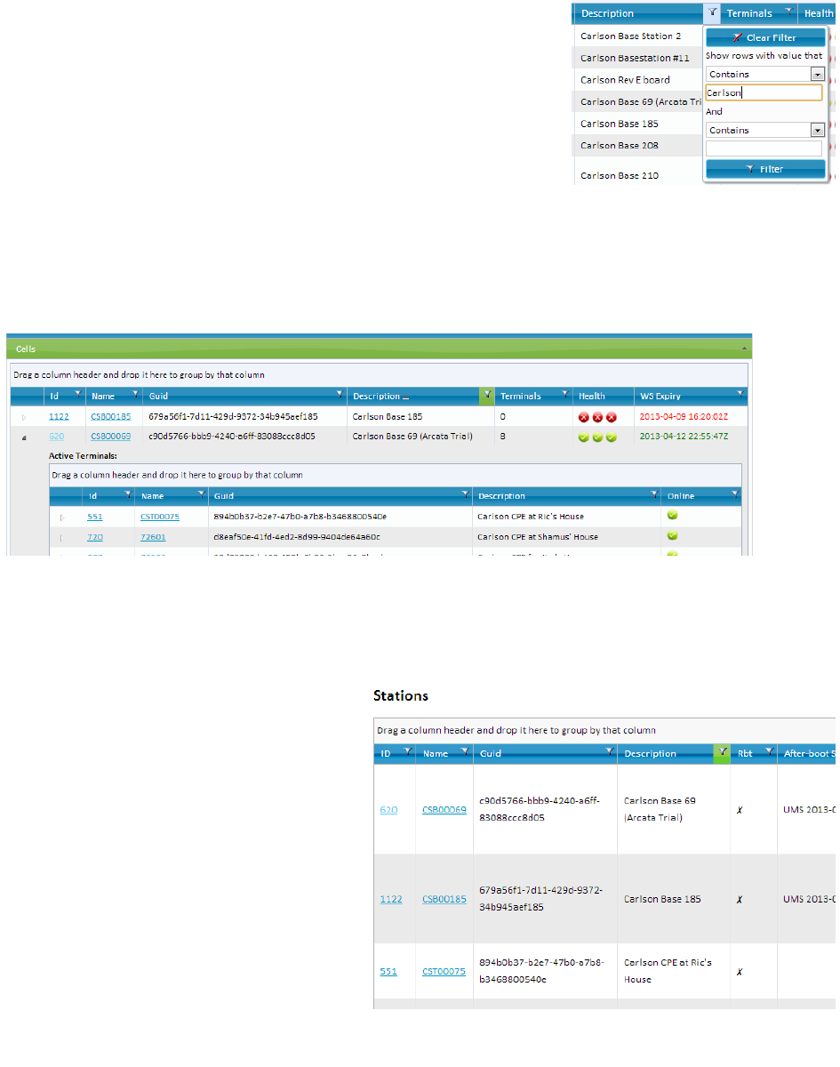
Click on the “Cells” drop-down tab. This section displays each
Basestation assigned to your account and the associated CPEs
of each. You will see each station name, its Globally Unique
Identifier (GUID), description and health.
To filter the list of Basestations, click on the filter icon next to
any column heading. Enter any keywords you wish to search for
and press Enter, or click the “Filter” button.
After a brief delay, you will see the results of your search. Figure 26: Filtering Choices
Click on the arrow to the left of any Basestation. This will
expand the “cell” list, showing associated CPEs.
Clicking the “Id” or “Name” hyperlink of any station will give you a popup “Station Properties”
window. See Section 5.7 of this manual to learn more about Station Properties.
Figure 27: Expanded "Cell" List
5.5. Stations
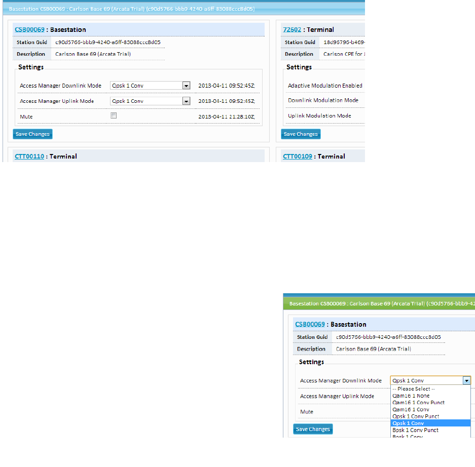
Click on the “Stations” tab at the top of the OMC window.
This is a list of radios assigned to your
account. The OMC will only display
radios assigned to your account. If an
expected radio does not appear in this
list, you must make a request to Carlson
Support for a database update.
Each radio will have a customized name
and description. Unless requested
otherwise, Carlson will use a default
naming convention. Basestation names
begin with “CSB”, followed by the serial
number with one leading zero removed
(i.e., “CSB00123”). CPE names begin
with “CST”, using the same serial
number syntax (i.e., "CST00123").
Figure 28: Stations Display
The “Rbt” column shows if the
Page | 20
PRELIMINARY RELEASE
*** This is a confidential document. Do not distribute. ***
Basestation is currently in a “soft-reboot” state, indicated by a checkmark. The radio is not
accessible while in this state; access will resume upon successful completion of the boot
sequence.
Note: the Basestation boot process can take up to five (5) minutes or more.
The “Last Reported” column displays the amount of time elapsed since your Basestation last
reported state to the OMC. Active Basestations always report in less than one minute, indicated
in green.
5.6. Cell Control
Click the “Cell Control” tab at the top of the OMC window.
Figure 29: Cell Control Display
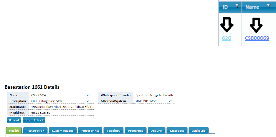
Cell Control is the area of the OMC where you can view and edit the settings affecting the
performance of each radio.
As of April 13, 2013, this is the only area of the OMC where end users can make changes.
After making your desired changes, click the “Save Changes” button to apply them.
Use the “Mute” button to disable the radio on the Basestation. Place a check into the box to
enable this feature. This will disable the Basestation radio. Your RuralConnect® network will not
function with this feature enabled.
5.6.1. Modulation Modes
The performance of each RF link is determined by the
signal quality and the modulation mode used. These
drop-down menus allow you to select the modulation
mode for both the uplink and downlink of each CPE.
You can only change the setting for one station at a
time. After making changes, press the “Save Changes”
button. The changes will be applied and the Cell
Control tab will reset.
Complex modulation types are at the top of the list,
followed by simpler modulation types and various
forms of forward error correction (FEC). Complex Figure 30: Modulation Settings
Page | 21
PRELIMINARY RELEASE
*** This is a confidential document. Do not distribute. ***
modulations, such as quadrature amplitude modulation (QAM) provide a mechanism for higher
bit rates, and thus more available throughput. These complex modulations, however, have a
negative impact on the receive threshold of the radio, the signal level at which the link is
unreliable.
Modulation modes are in order of net bit rate, with the highest bit rate at the top of the list. The
effective throughput of an RF link is based on the net bit rate, less the PHY and link-layer
overheads. Modulation modes in Cell Control include acronyms for modulation types and
abbreviations for FEC types. “Conv_Punct”, a 3/4 punctured convolutional coding rate, provides
25% FEC, reducing the available payload to 75% of the gross bit rate. “Conv” is a 1/2
convolutional coding rate. This 50% FEC produces a reliable communications channel, while
reducing the available payload to 50% of the gross bit rate.
Basestations will commonly use “Qpsk_1_Conv” for the Uplink and Downlink modulation modes.
This modulation mode provides a good link reliability and provides enough bandwidth for system
controls
Set your CPE stations with the modulation mode that meets the needs of the installation and
application. Stronger signal-to-noise ratios will allow the use of higher modulation modes,
providing higher throughput. An SNR of 25 or greater will allow the use of QAM16 with FEC,
while an SNR of 30 or greater is required before you can disable FEC (“QAM16_None”).
For troubleshooting RF links with errors and/or poor signals, select a lower modulation mode.
An “Adaptive Modulation” button is available, which will enable dynamic control of the link
modulation mode, to maintain link stability in varied conditions. Although this is useful feature, a
fixed modulation type will provide better performance.
5.7. Station Properties
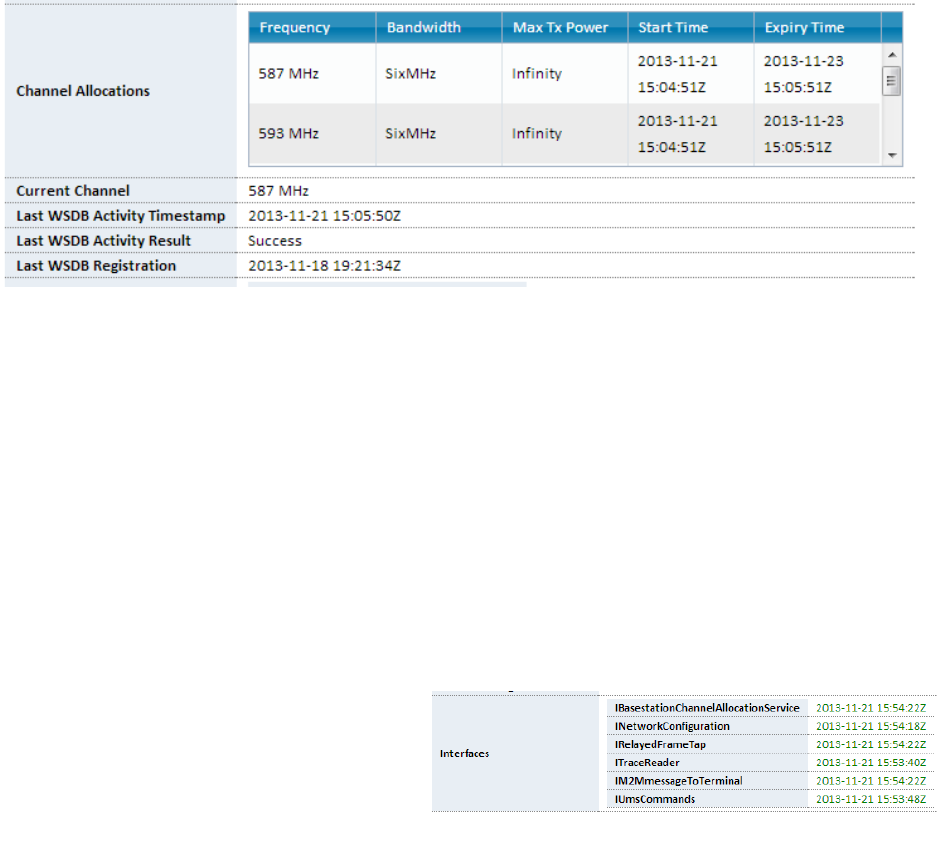
From many areas around the OMC, you can click on the “Id” or “Name”
hyperlink of a station to open a “Station Properties” pop-up window.
Clicking the ID will open a new webpage. Clicking the Name will open a
pop-up window.
Basestations and CPEs have similar properties, along with sections
unique to each role. The upper section includes the Stations Details. The
lower section includes various tabs for each control and status area of the
station.
Figure 31: Station Links
5.7.1. Basestation Details
Figure 32: Basestation Details
For smaller screens, you can maximize the window by clicking its header/title bar.
Page | 22
PRELIMINARY RELEASE
*** This is a confidential document. Do not distribute. ***
Basestation Details include the name, description, GUID, IP Address, whitespace database
provider. You will also see the “AfterBootSystem”, the boot image used to initialize the
Basestation with the OMC upon establishing a connection.
You will also see two buttons. To perform a “soft reboot” of a Basestation, click the “Reboot”
button. To restart the station software alone, without a reboot, click the “Restart Stack” button.
Health
The first Station Properties tab, “Health”, is open by default, displaying the last reported date
and time for each control interface. Basestations also report the current channel and channel
allocations.
Channel Allocations
The spectrum database provides a list of available channels, based on the registration details.
The OMC displays the allocated channel is a list on this tab.
Figure 33: Channel Allocation
An active RuralConnect network requires an active channel allocation. You can find this
information in other areas of the OMC, as well.
On the right of each channel listed, you will see the expiration, or “Expiry Time”. This is a color-
coded indicator of the expiration of the channel allocation lease provided by the spectrum
database. If the Basestation fails to acquire a new lease before the Expiry Time shown, it will
cease transmission. The radio will not transmit until the OMC obtains a new channel allocation
lease.
Underneath the channel allocations, you will also see the current channel and details of the last
spectrum database activity results.
Interfaces
Each radio has multiple network connections created for controls to and from the OMC. This
value indicates the most recent date and time interface successfully established a connection to
the station. If an Internet connection fails,
these interfaces will fail to communicate.
During such down time, the OMC cannot
control the station, though local network
functionality will continue until the channel
Figure 34: Interface Date/Time Stamps
Page | 23
PRELIMINARY RELEASE
*** This is a confidential document. Do not distribute. ***
se.
allocation lease expires.
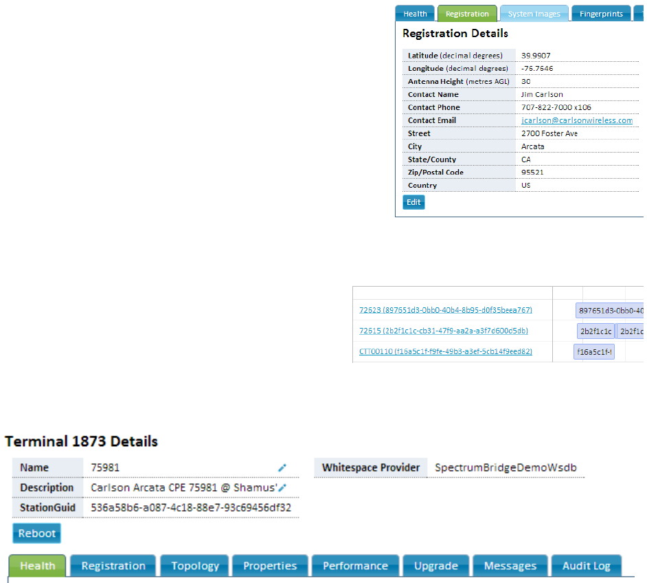
Registration
The Registration Details include the station site
coordinates, antenna height and your contact
information. These fields are required for registration
with the spectrum databa
Click the “Edit” button, fill out all the fields and then click
the “Confirm” button.
Activity
Click on the “Activity” tab to view the RF network history
of the RuralConnect Basestation.
This is a list of all currently and recently active CPE
connections, listed by GUID. On the right, a bar
graph indicates the timeline of each active CPE
connection. Click and drag this timeline to scroll it
left and right, viewing the history of these
connections.
Figure 35: Base Registration Details
Figure 36: Active Terminals
5.7.2. CPE Properties/Details
This screen displays the name, description, GUID and spectrum database provider.
Figure 37: CPE Details
Click the “Reboot” button to reboot the CPE from this screen.
Health
The first Station Properties tab, “Health”, is open by default, displaying the last reported date
and time for each control interface. Stations also report the current channel and channel
allocations.
Page | 24
PRELIMINARY RELEASE
*** This is a confidential document. Do not distribute. ***
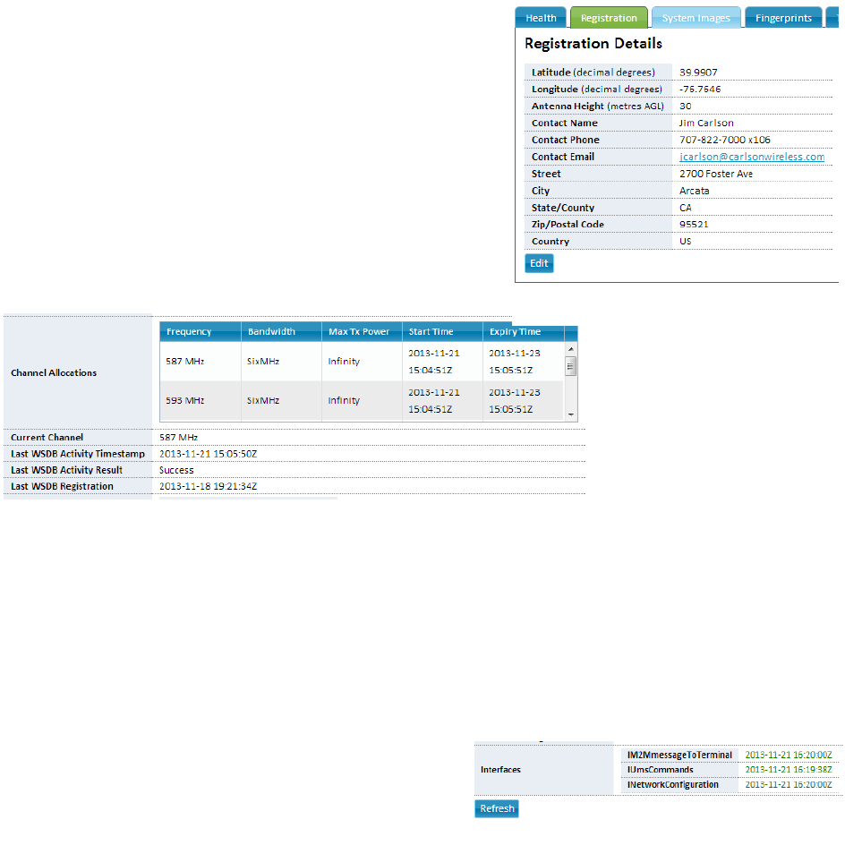
Registration
The Registration Details include the station site
coordinates, antenna height and your contact
information. These fields are required for registration
with the spectrum database.
Click the “Edit” button, fill out all the fields and then click
the “Confirm” button.
Channel Allocations
The spectrum database provides a list of available
channels, based on the registration details. The OMC
displays the allocated channel is a list on this tab.
Figure 38: CPE Registration Details
Figure 39: CPE Channel Allocations
On the right of each channel listed, you will see the expiration, or “Expiry Time”. This is a color-
coded indicator of the expiration of the channel allocation lease provided by the spectrum
database. If the CPE fails to acquire a new lease before the Expiry Time shown, it will cease
transmission. The radio will not transmit until the OMC obtains and allocates a list of available
channels.
Underneath the channel allocations, you will also see the current channel and details of the last
spectrum database activity results.
Interfaces
Each radio has multiple network connections
created for controls to and from the OMC. This
value indicates the most recent date and time each
interface successfully established a connection to
the station. If an Internet connection fails, these
interfaces will fail to communicate. During such down time, the OMC cannot control the station,
though wireless network functionality will continue until the channel allocation lease expires.
Figure 40: Interfaces Last Reported
Page | 25
PRELIMINARY RELEASE
*** This is a confidential document. Do not distribute. ***
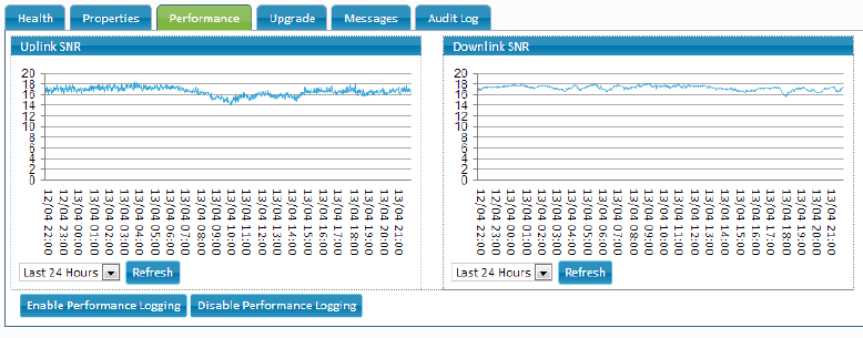
Performance
This tab provides a line graph of the uplink and downlink SNR history for the CPE.
Figure 41: SNR History Graph
The drop-down menu allows a choice of timelines. Click “Enable/Disable Performance Logging”
to start/stop the log,
6. Appendices
6.1. Specifications
SYSTEM SPECIFICATIONS
Frequency Bands UHF 470-786 MHz (US and ETSI)
Channel Spacing 6 MHz (US), 8 MHz (ETSI)
Bandwidth 100 kHz (M2M) to 4.5 MHz (Rural BB)
Modulation QPSK, 16QAM
Data Rates 4, 6, 8, 12, and 16 Mb/s
Data Rate Control Dynamic or fixed
Receive Interface Proprietary technology is used to reduce
co-channel interference
RX Sensitivity -89 dBm for 10-6 BER using QPSK 1/2
-86 dBm for 10-6 BER using 16QAM 1/2
RX Blocking Resistance -50dBm TV transmission on chan N+2
-20 dBm cellular station transmissions
RX Max Signal -16dBm with full linearity
Operating Mode TDD (Time Division Duplexing)
User Ports 10/100 baseT Ethernet
Warranty Limited Warranty, USA
NETWORK SPECIFICATIONS
Multipoint Client Capacity 4096 (M2M)
Typical Client Loading 20 clients with 3Mb/1Mb residential SLA
Management Web-based browser using https interface
End-to-End Latency 30-100 ms typ.
Page | 26

PRELIMINARY RELEASE
*** This is a confidential document. Do not distribute. ***
REGULATORY SPECIFICATIONS
ACP and Spectrum Mask Meets FCC and Ofcom specifications
-55 dBr +/- 3 MHz relative to 12.2 dBm
(measured at 100 KHz increments)
ENVIRONMENTAL SPECIFICATIONS Operating Temperature -30° to 55° C
Operating Humidity Up to 95%, non-condensing
Shock and Vibration MIL-STD-810
SECURITY
Security Mechanism WPA2/AES-128 bit shared secret key
BASESTATION
Antenna System SISO with MIMO Space Diversity option
Antenna Connector “F” type female 75 Ohms
MECHANICAL SPECIFICATIONS
Unit Dimensions 19.6” x 6” x 1.75”
Enclosure Material Painted steel
Weight 5 lbs
Mounting 19 inch EIA 2 unit rack
POWER - INDOOR RACK MOUNT
Voltage 100-240 VAC, 50-60 Hz or 12 VDC
Current Tx: 30W, Rx: 15W, Idle: 13W
Connector POE
6.2. Warranty
Carlson Wireless Technologies, Inc. or Carlson Wireless USA, collectively referred to as
“Carlson“), will repair this product with new or rebuilt parts, free of charge, in the USA or Puerto
Rico for one (1) year from the date of original purchase in the event of a defect in material or
workmanship. You can obtain mail-in service in the USA during the warranty period from a
Carlson Factory Service Center by visiting http://www.carlsonwireless.com/support/rma-
request.html for an RMA (Return Materials Authorization) number. After receiving your RMA
number, ship your product adequately packed, postage paid and insured to the address
provided. This warranty extends to the original purchaser only. A purchase receipt or other proof
of the date of original purchase will be required before the rendering of warranty services. This
warranty only covers failures due to defects in materials or workmanship, which occur during
normal use. It does not cover damages incurred in shipment or failures caused by products not
supplied by Carlson. It also does not cover failures which result from accident, misuse, abuse,
neglect, mishandling, misapplication, alteration, modification, lightning, power line surge,
introduction of sand, dust, humidity and/or liquids, or service by anyone other than a Carlson
Factory Service Center or authorized Carlson Service Center, or damage that is attributable to
acts of God.
Limits and Exclusions
There are no express warranties except as listed above.
Page | 27
PRELIMINARY RELEASE
*** This is a confidential document. Do not distribute. ***
CARLSON SHALL NOT BE LIABLE FOR INCIDENTAL OR CONSEQUENTIAL DAMAGES
RESULTING FROM THE USE OF THIS PRODUCT OR ARISING OUT OF ANY BREACH OF
THIS WARRANTY. ALL EXPRESS AND IMPLIED WARRANTIES, INCLUDING THE
WARRANTIES OF MERCHANTABILITY AND FITNESS FOR A PARTICULAR PURPOSE, ARE
LIMITED TO THE APPLICABLE WARRANTY PERIOD SET FORTH ABOVE.
Some states do not allow the exclusion or limitation of incidental or consequential damages or a
limitation on how long an implied warranty lasts, so the above exclusions or limitations may not
apply to you. This warranty gives you specific legal rights. You may also have other rights, which
vary from state to state. If a problem with this product develops during or after the warranty
period, you may contact your dealer or service center.
6.3. Acronyms/Abbreviations
API application programming interface
CPE Customer Premises Equipment (Client Station)
dB decibel
EMC electromagnetic compatibility
ESD electrostatic discharge
FTDI Future Technology Devices International
GUI graphical user interface
IP Internet protocol
LAN local area network
OMC Operations and Management Center
OSHA Occupational Safety and Health Administration
QAM Quadrature amplitude modulation
RF Radio frequency
RG-11 75 ohm cable standard (1.63 mm core with triple/quad
shielding)
RG-6/U 75 ohm cable standard (1.0 mm core with double shielding)
RMA return material authorization
Rx receive
SC-FDE Single Carrier Frequency Domain Equalization
STA Special Temporary Authority
SU subscriber unit
Tx transmit
USB Universal Serial Bus
6.4. Glossary
Access Point
An access point is a device that allows a wireless device (or multiple devices) to connect to a
network (or the Internet).
Attenuation
Amplitude reduction of an electrical signal.
Page | 28
PRELIMINARY RELEASE
*** This is a confidential document. Do not distribute. ***
bps
Bits per second, the rate of at which data is transmitted.
Byte
A digital “word” usually made up of eight bits.
CPE
Customer Premise Equipment, or “Client Station”; an endpoint, usually at a customer’s
location, that connects to a network (or the Internet) via an access point
Ethernet
A set of computer networking technologies for local area networks (LANs).
IP
Internet protocol provides for transmitting blocks of data between hosts identified by fixed-
length addresses.
LAN
Local area network, a privately owned network that offers high-speed communications
channels connecting information processing equipment in a limited geographic area.
Modulation
Any of several techniques for combining user information with a transmitter carrier signal.
Packet
Data encapsulated with control information. The three principal elements of a packet include
the header, text, and trailer bits (for error detection and correction). A header contains the data
needed to route the packet through a network to its final destination.
Quadrature amplitude modulation (QAM)
A modulation method that conveys two bit streams by changing the amplitudes of two carrier
waves.
Router
A network device used to forward data between multiple networks.
Single Carrier Frequency Domain Equalization (SC-FDE)
An alternative to solve the common multipath issues associated with commonly-used OFDM
systems. This advanced carrier technique improves performance of a non-line-of-sight
wireless system, allowing the RuralConnect® to deliver high-speed Internet access to areas
where traditional wireless technologies will not operate.
Single Carrier Frequency Division Multiple Access (SC-FDMA)
A frequency-division multiple access scheme that deals with the assignment of multiple users
to a shared communication resource.
Special Temporary Authority (STA)
A type of broadcast license which temporarily allows a broadcast station to operate outside of
its normal technical or legal parameters.
Page | 29

PRELIMINARY RELEASE
*** This is a confidential document. Do not distribute. ***
6.5. Useful URLs
Carlson provides the following URLs for reference purposes only. This is not a comprehensive
source for this information. The purchaser must be familiar themselves with all relevant safety
and/or regulatory information prior to the operation of a RuralConnect® system. Carlson does
not authorize untrained and/or unqualified personnel to work on the system without the
supervision of a qualified technician.
FCC Experimental License Application License for TVWS Device Operation
https://apps.fcc.gov/oetcf/els/forms/STANotificationPage.cfm
US Federal Regulations
Title 47: Telecommunications
http://ecfr.gpoaccess.gov/cgi/t/text/text-idx?c=ecfr&tpl=/ecfrbrowse/Title47/47tab_02.tpl
Part 15: Radio Frequency Devices
http://ecfr.gpoaccess.gov/cgi/t/text/text-
idx?c=ecfr;sid=f1da62e9cb3d6edca075f32556594ab7;rgn=div5;view=text;node=47%3A1.0.1.1.16;id
no=47;cc=ecfr
Subpart H: Television Band Devices
http://ecfr.gpoaccess.gov/cgi/t/text/text-
idx?c=ecfr&sid=ec1bcacee1c437294c3e48e0acbf755b&rgn=div6&view=text&node=47:1.0.1.1.16.8&
idno=47
Spectrum Registration
FCC information regarding White Space Database Administration
http://www.fcc.gov/encyclopedia/white-space-database-administration
ESD Protection
General information
http://en.wikipedia.org/wiki/Electrostatic_discharge
ESD Association
http://www.esda.org/
IPC: Association Connecting Electronics Industries
http://www.ipc.org/default.aspx
Cable information
General Coaxial Cable information
http://en.wikipedia.org/wiki/Coaxial_cable
General F Connector information
http://en.wikipedia.org/wiki/F_connector
Page | 30

PRELIMINARY RELEASE
*** This is a confidential document. Do not distribute. ***
Page | 31
Weatherproofing RF connections
http://www.dxengineering.com/pdf/WeatherProofingCoax-TechTip.pdf
RF Safety information
FCC: Radio Frequency Safety
http://transition.fcc.gov/oet/rfsafety/rf-faqs.html
VHF/UHF Exposure information/warnings
http://transition.fcc.gov/oet/rfsafety/rf-faqs.html#Q17
Tower Safety information
Tower installation crews MUST be; adequately trained, licensed, and properly equipped with all
of the safety equipment required by law. Failure to follow federal and/or local regulations may
result in; warranty voiding equipment damage, personal injury, fines, and/or the loss of
applicable licenses. Information provided here is strictly for reference purposes.
OSHA Guidelines: Part 1910 – Occupational Safety and Health Standards
http://www.osha.gov/pls/oshaweb/owasrch.search_form?p_doc_type=STANDARDS&p_toc_level=1
&p_keyvalue=1910
General Tower Safety Guide
http://homepower.com/view/?file=HP128_pg66_Woofenden
General TV White Space information
http://en.wikipedia.org/wiki/White_spaces_(radio)
General IEEE 802.22 information
http://en.wikipedia.org/wiki/IEEE_802.22
Manufacturer Information
Carlson Wireless Technologies, Inc
http://www.carlsonwireless.com/
Neul Ltd
http://www.neul.com/
6.6. Manual Revision Notes
Revision History
Rev 1.5. January 2013 Development draft
Rev 1.6. April 2013 Preliminary release draft
Rev 1.74 June 2013 New OMC release, removed a few tabs
Rev 1.74c November 2013 Overview, Current & Allocated Channels
Rev 1.74d December 2013 Verified mandatory FCC language