ChronoTrack Systems CON-M800-USA1 MC627 Timekeeping System User Manual ChronoTrack UserManual v1 2
ChronoTrack Systems LLC MC627 Timekeeping System ChronoTrack UserManual v1 2
Users Manual

ChronoTrackSystems,Inc.ChronoTrackUserManualTableofContents
Issued:January2010
ChronoTrackSystems,Inc.
111EastDiamondAvenue
Evansville,Indiana47711
U.S.A.
812‐423‐7800Main
314‐406‐7243Sales
812‐759‐7877Support
812‐423‐7801Fax
www.chronotrack.com
ChronoTrackUserManual

ChronoTrackSystems,Inc.ChronoTrackUserManualTableofContents
Issued:January2010 1‐2
© Copyright 2010 ChronoTrack Systems, Inc. All rights reserved.
“ChronoTrack”, “D-Tag”, and “D-Tag Interrogator” are trademarks of ChronoTrack Systems, Inc. “Windows” is a
registered trademark of Microsoft Corporation in the United States and other countries. All other trademarks used
herein are property of their respective owners.
ChronoTrack Systems, Inc. makes no warranty of any kind with regard to this material, including, but not limited to,
the implied warranties of merchantability and fitness for a particular purpose. ChronoTrack Systems shall not be liable
for errors contained herein or for incidental or consequential damages in connection with the furnishing, performance,
or use of this material.
This document contains proprietary information, which is protected by copyright. No part of this document may be
photocopied, reproduced, or translated into another language without the prior written consent of ChronoTrack
Systems.
ChronoTrack Systems shall not be liable for technical or editorial errors or omissions contained herein. The
information is provided “as is” without warranty of any kind and is subject to change without notice.

ChronoTrackSystems,Inc.ChronoTrackUserManualTableofContents
Issued:January2010 1‐3
1 TableofContents
1 Table of Contents ............................................................................................................................................. 1-3
2 Introduction ....................................................................................................................................................... 2-1
2.1 About This Guide .................................................................................................................................... 2-1
2.2 ChronoTrack System Overview .............................................................................................................. 2-1
3 Gator Setup and Configuration ......................................................................................................................... 3-1
3.1 Possible Gator Configurations ................................................................................................................ 3-1
3.2 Positioning and Linking Gators ............................................................................................................... 3-3
3.3 Connecting Antennas .............................................................................................................................. 3-4
3.4 Creating a “Dead Zone” .......................................................................................................................... 3-4
4 Controller Setup ................................................................................................................................................ 4-1
4.1 The Controller Interface .......................................................................................................................... 4-1
4.1.1 Status Indicator LEDs ......................................................................................................................... 4-2
4.2 Powering ON ........................................................................................................................................... 4-3
4.3 Pre-Event Configuration .......................................................................................................................... 4-3
4.4 Charging ................................................................................................................................................. 4-3
5 Using BoxScore ................................................................................................................................................ 5-1
5.1 The Main Screen ..................................................................................................................................... 5-1
5.1.1 Creating a Gun Start Timestamp and File Markers ............................................................................ 5-1
5.2 Configure Menu ...................................................................................................................................... 5-2
5.2.1 Network Configuration ........................................................................................................................ 5-2
5.2.1.1 Setting the Server Address ........................................................................................................................ 5-2
5.2.1.2 Advanced Network Configuration ............................................................................................................ 5-3
5.2.2 Powering ON/OFF Internal Components ............................................................................................ 5-3
5.2.3 Point Configuration ............................................................................................................................. 5-3
5.2.3.1 Point Configuration Data Input ................................................................................................................. 5-4
5.2.4 Copying Files to USB ......................................................................................................................... 5-5
5.2.4.1 File Copy Status Messages ....................................................................................................................... 5-5
5.2.5 Setup Wizard ...................................................................................................................................... 5-6
5.3 System Menu .......................................................................................................................................... 5-6
5.3.1 Shutting Down the System ................................................................................................................. 5-6
5.3.2 Setting the Time and Date .................................................................................................................. 5-7
5.3.2.1 Setting the Time on a Controller ............................................................................................................... 5-7
5.3.2.2 Synchronizing the Time on Multiple Controllers ...................................................................................... 5-7
5.3.2.3 Setting the Time with GPS ........................................................................................................................ 5-7
5.3.3 Maintenance ....................................................................................................................................... 5-8
5.3.3.1 Fast-Charging............................................................................................................................................ 5-8
5.3.3.2 Dry Mode .................................................................................................................................................. 5-8
5.4 Status Menu ............................................................................................................................................ 5-9
5.4.1 System Status .................................................................................................................................... 5-9
5.4.2 Reader Status .................................................................................................................................. 5-10

ChronoTrackSystems,Inc.ChronoTrackUserManualTableofContents
Issued:January2010 1‐4
5.4.2.1 Sending Reader Commands .................................................................................................................... 5-10
5.4.2.2 Checking Connected Antennas ............................................................................................................... 5-10
5.4.3 Establishing Network Connections ................................................................................................... 5-10
5.4.3.1 Establishing a Cellular (GPRS) Connection ........................................................................................... 5-12
5.4.3.2 Establishing a Wireless Connection ........................................................................................................ 5-12
5.4.3.3 Establishing a Wired Connection ............................................................................................................ 5-13
5.4.4 Operations ........................................................................................................................................ 5-13
5.4.4.1 Immediate Mode ..................................................................................................................................... 5-13
5.4.4.2 Zeroing Tag Counts ................................................................................................................................ 5-13
5.5 Messages Menu .................................................................................................................................... 5-14
5.5.1 Acknowledging Alerts ....................................................................................................................... 5-15
5.6 Updating BoxScore ............................................................................................................................... 5-15
6 Using CCSLite .................................................................................................................................................. 6-1
6.1 Configuration of CCSLite ........................................................................................................................ 6-1
6.2 Establishing Controller Connections ....................................................................................................... 6-1
6.3 CCSLite Raw Mode ................................................................................................................................. 6-2
6.4 Adding a Firewall Exception for CCSLite ................................................................................................ 6-2
7 Using SimpleClient ........................................................................................................................................... 7-1
7.1 SimpleClient Operation Modes ............................................................................................................... 7-1
7.1.1 Local Network Mode ........................................................................................................................... 7-1
7.1.2 Internet Server Mode .......................................................................................................................... 7-1
7.2 Connecting to the Server and Retrieving Data ........................................................................................ 7-1
7.3 Streaming Data ....................................................................................................................................... 7-2
7.4 Tag Invalidation ....................................................................................................................................... 7-3
7.5 File Formats ............................................................................................................................................ 7-3
7.6 Saving SimpleClient Data ....................................................................................................................... 7-3
7.7 Filtering Data ........................................................................................................................................... 7-4
7.7.1 Creating Tag Ranges for an Event ..................................................................................................... 7-4
7.8 Creating Virtual Points ............................................................................................................................ 7-4
7.9 Creating and Using an Announcer Line .................................................................................................. 7-5
7.10 Loading Controller Files .......................................................................................................................... 7-5
7.11 Establishing a Direct Socket Connection with Scoring Software ............................................................. 7-6
7.12 Setting Time Intervals for Pass Counts and Same Tag Observations .................................................... 7-6
7.13 Creating Time Shifts ................................................................................................................................ 7-6
7.13.1 Disabled ........................................................................................................................................ 7-6
7.13.2 UTC to Local Timezone ................................................................................................................. 7-7
7.13.3 Manual ........................................................................................................................................... 7-7
7.13.4 00:00 Start ..................................................................................................................................... 7-7
7.14 Renaming Events/Points ......................................................................................................................... 7-7
7.15 More SimpleClient Functions .................................................................................................................. 7-7
8 Printing and Re-encoding D-Tags ..................................................................................................................... 8-1

ChronoTrackSystems,Inc.ChronoTrackUserManualTableofContents
Issued:January2010 1‐5
8.1 Printer Installation ................................................................................................................................... 8-1
8.1.1 Printer Setup - Hardware .................................................................................................................... 8-1
8.1.2 Printer Setup – Software .................................................................................................................... 8-4
8.1.3 Printer Setup - Windows ..................................................................................................................... 8-5
8.2 RFID Encoder Installation ....................................................................................................................... 8-9
8.3 Barcode Scanner Installation ................................................................................................................ 8-12
8.4 Installation of Software .......................................................................................................................... 8-13
8.4.1 PrintDTag Software .......................................................................................................................... 8-13
8.4.2 Wasp Labeler – Barcode Label Software ......................................................................................... 8-13
8.5 PrintDTag Software ............................................................................................................................... 8-14
8.5.1 PrintDTag Main Menu ...................................................................................................................... 8-14
8.5.2 PrintDTag Default Settings ............................................................................................................... 8-14
8.5.3 Printing D-Tags ................................................................................................................................ 8-17
8.5.4 Validating D-Tags ............................................................................................................................. 8-19
8.5.5 Re-encoding D-Tags ........................................................................................................................ 8-20
8.5.6 Reading D-Tags ............................................................................................................................... 8-21
9 Troubleshooting ................................................................................................................................................ 9-1
10 Appendix .................................................................................................................................................... 10-1
10.1 System Specifications ........................................................................................................................... 10-1
10.2 File Format Specifications ..................................................................................................................... 10-1
10.2.1 Available Fields ........................................................................................................................... 10-2
10.2.2 File Format Indicator .................................................................................................................... 10-2
10.2.3 Fixed Width Size Considerations ................................................................................................. 10-5
11 Index ................................................................................................................................................................ 1

ChronoTrackSystems,Inc.ChronoTrackUserManualIntroduction
Issued:January2010 2‐1
2 Introduction
ChronoTrack is a cost-effective timing and tracking system for use at athletic events, such as a marathon or a road
race. ChronoTrack “D-Tag” technology uses specially designed RFID controllers and antennas to track an EPC-
certified, UHF RFID tag that is attached to the runner’s foot during the race. Using this system, ChronoTrack
Systems, Inc. provides full-service race timing packages, including internationally certified race timers, bibs, tags, and
race timing equipment.
2.1 AboutThisGuide
This guide describes how to set up, configure, and use ChronoTrack system components to time and track athletic
events.
This symbol indicates cautions and warnings where necessary.
2.2 ChronoTrackSystemOverview
The ChronoTrack system is comprised of the components listed below. See System Specifications in the Appendix
for more details.
D-Tag Interrogator (“Gator”)
A D-Tag Interrogator, also known as a Gator, is a specially designed modular track that is placed at each
timing location. Each Gator is 42 inches long and is connected with other Gators until they span the entire
width of the roadway at the designated timing location.
D-Tag Interrogator Core (Antenna)
A D-Tag Interrogator Core Antenna fits inside each Gator and reads participant D-Tags as they pass over
that portion of track. This information is then sent to the ChronoTrack controller.
ChronoTrack Controller (400 or 800 Series)
A ChronoTrack controller stores and reads the RFID data that is recorded by the antennas at its timing
location. A 400 Series controller can support a configuration of up to four Gators (a span of up to 14 feet),
and the 800 Series controller can support a configuration of up to eight Gators (a span of up to 28 feet).
DC Power Cable
The DC Power Cable enables you to run the ChronoTrack controller from an auxiliary battery source.

ChronoTrackSystems,Inc.ChronoTrackUserManualIntroduction
Issued:January2010 2‐2
Cable Sets (Short or Long)
Cable sets connect the Gator Core Antennas together and to the controller. The short cable set supports a
full 400 Series controller, and the long cable set in combination with a short set supports a full 800 Series
controller.
ChronoTrack Software
The system comes equipped with the following software:
BoxScore software that enables information to be downloaded from a controller during or after an
event using a simple touch screen interface.
SimpleClient software that retrieves and manipulates controller data for use in third-party scoring
software.
CCSLite software that helps establish LAN and Wi-Fi connections with the SimpleClient software.
PrintDTag software is also available separately for printing your own D-Tags.
DOTregulationsprohibittheshippingoflithiumbatteriesbyaircraftorvessel.Shippedcontrollersmustincludethe
followinglabel:“LITHIUMBATTERIES:FORBIDDENFORTRANSPORTABOARDAIRCRAFTANDVESSEL”.
ChronoTrackSystems,Inc.ChronoTrackUserManualGatorSetupandConfiguration
Issued:January2010 3‐1
3 Gato rSetupandConfiguration
The ChronoTrack Controller and modular Gators are versatile and allow for multiple configurations. Timing locations
can be configured to be as narrow as 42 inches or as wide as 56 feet of continuous lengths, with one controller
covering as much as 28 feet.
3.1 PossibleGatorConfigurations
In preparation for an event, it is important to determine the width of the roadway at the designated timing locations.
This information is used to determine which configurations of Gators and controllers will best suit your needs. With
the ChronoTrack system, a backup start line is recommended to increase overall performance of the system and as a
fail-safe measure to ensure every tag is read.
The following are some possible configurations. Note that spacing is not to scale.
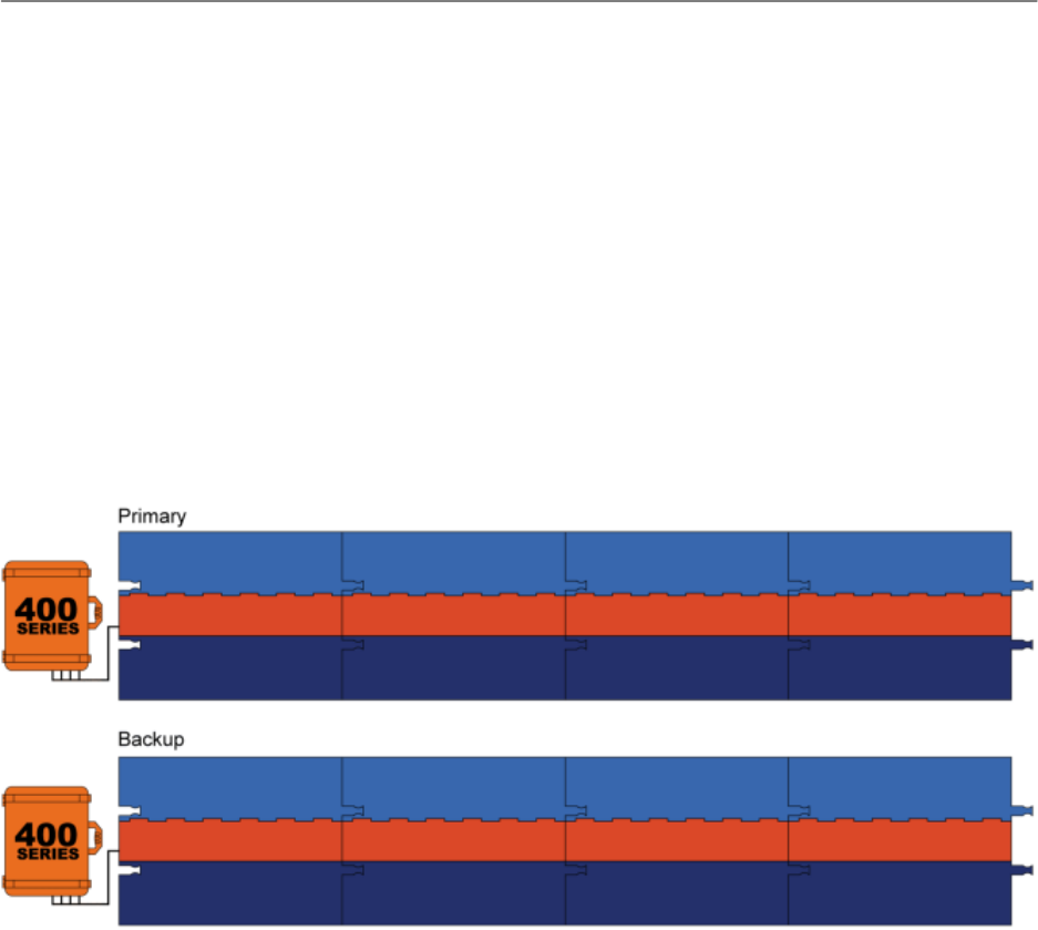
Primary and Backup with Two 400 Series Controllers
14 Feet (4.27 Meters)
UnnetworkedPointConfiguration:1Controller,1Reader,4Gators
NetworkedPointConfiguration:1Controller,1Reader,4Gators
ChronoTrackSystems,Inc.ChronoTrackUserManualGatorSetupandConfiguration
Issued:January2010 3‐2
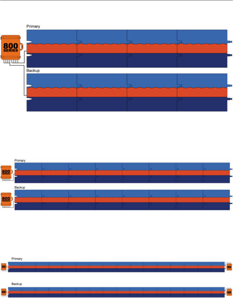
Primary and Backup on a Single 800 Series Controller
14 Feet (4.27 Meters)
UnnetworkedPointConfiguration:1Controller,2Readers,8Gators
NetworkedPointConfiguration:N/A
Primary and Backup with Two 800 Series Controllers
28 Feet (8.53 Meters)
UnnetworkedPointConfiguration:1Controller,2Readers,8Gators
NetworkedPointConfiguration:2Controllers,4Readers,16Gators
Primary and Backup with Four 800 Series Controllers
56 Feet (17.07 Meters)
UnnetworkedPointConfiguration:1Controller,2Readers,8Gators
NetworkedPointConfiguration:4Controllers,8Readers,32Gators
ChronoTrackSystems,Inc.ChronoTrackUserManualGatorSetupandConfiguration
Issued:January2010 3‐3
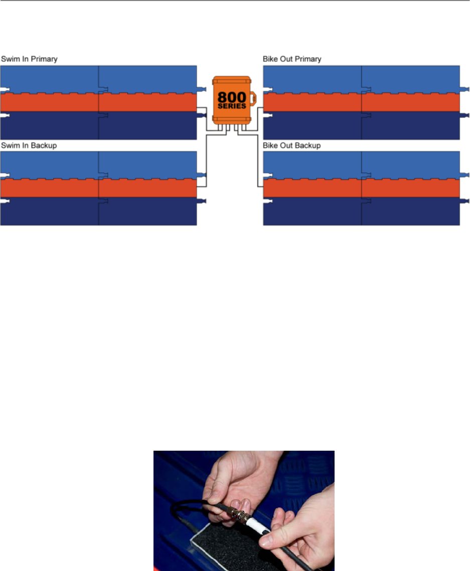
Primary and Backup Triathlon In and Out on a Single 800 Series Controller
7 Feet (2.13 Meters)
UnnetworkedPointConfiguration:1Controller,2Readers,8Gators
NetworkedPointConfiguration:N/A
3.2 PositioningandLinkingGators
To position and link Gators, complete the following procedure:
1. Position the Gators on the ground with the cable compartment hinges facing in the direction from which
runners will be approaching, and then link the connecting ends together. Primary and backup lines should
be spaced 10 to 12 feet apart.
2. Insert the Impinj Threshold antenna into the cable compartment of each Gator, placing it in the direction of
the controller with the writing on top. The Impinj logo will face the runners.
3. Starting with the Gator farthest from the controller, connect the Core antennas together using the
appropriate cable set for your configuration. When the connectors tangibly ‘click’, the cables are connected
correctly.
4. Pass the cables through the Gators using the top trough in the cable compartments. Make sure the cables
do not cross over the top of a trough. This can cause the lid of the Gator to close unevenly.
5. Connect the cables from the nearest Gator to the corresponding ports on the controller, matching the color
of each cable to the color of the port (Red cable to red port, blue to blue, etc.)
ChronoTrackSystems,Inc.ChronoTrackUserManualGatorSetupandConfiguration
Issued:January2010 3‐4
6. The only antenna licensed for use with this controller is the Impinj Threshold Antenna P/N: IPJ-A031-USA0E
using the cable sets provided by ChronoTrack Systems LLC. CAUTION – Any changes or modifications to
antenna and or cables used to attach the antennas to the controller without the express permission of
ChronoTYrack System LLC will void the user’s authority to operate this equipment.
3.3 Creatinga“DeadZone”
In order to avoid cross-reads when lines are placed next to each other, for example, two races finishing at the same
location on different ChronoTrack lines, it is necessary to either create an 8’ x 12’ “dead zone” or use a reflective
insulation barrier.

ChronoTrackSystems,Inc.ChronoTrackUserManualControllerSetup
Issued:January2010 4‐1
4 ControllerSetup
4.1 TheControllerInterface
ChronoTrack Controllers housed in crush-proof, waterproof, heat-resistant transport cases. The cases also provide
magnetized lid supports to shield the controller interface during inclement weather. In harsh conditions, you can place
controllers in plastic bags for further protection.
The controllers run on the Windows CE operating system and are pre-loaded with BoxScore software for easy setup
and configuration. A touch panel LCD screen is used to interface with the controller.
Two RFID readers are inside each controller. The readers correspond to the ports on the controller: Ports 1-4
correspond to Reader 1, and Ports 5-8 correspond to Reader 2. To ensure accurate D-Tag readings, tags are read
within eight feet of a timing line, and the data is tracked and calculated as participants pass over the line so that the
most accurate time is reported.
ChronoTrackSystems,Inc.ChronoTrackUserManualControllerSetup
Issued:January2010 4‐2
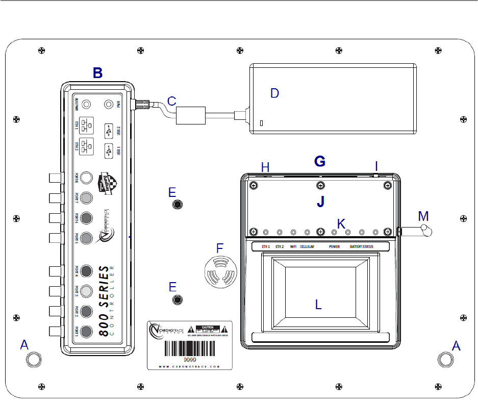
The controller interface and legend are shown as follows:
A. LidSupportMagnets
B. ConnectionMesa
C. ACPowerCable
D. PowerSupply
E. Wi‐FiAntennas
F. Loudspeaker
G. DisplayMesa
H. ResetButtonPinhole
I. PowerSwitch
J. TPC(TouchPanelComputer)Mesa
K. StatusIndicatorLEDs
L. TouchPanelScreen
M. CellularAntenna(GPRS)
4.1.1 StatusIndicatorLEDs
When a controller is powered ON, LEDs on the Display Mesa light up depending on the status/activity. The LEDs are
described in the following table.

ChronoTrackSystems,Inc.ChronoTrackUserManualControllerSetup
Issued:January2010 4‐3
LED Name Color Function
ETH 1 Flashing green Activity
None No activity
ETH 2 Flashing green Activity
None No activity
WIFI Flashing green Activity
None No activity
Cellular Flashing green Activity
None No activity
Power Green Power ON
None Power OFF
Battery Status Green Total battery charge over 50%
Amber Total battery charge at 50% or
less
Red Total battery charge at 10% or
less
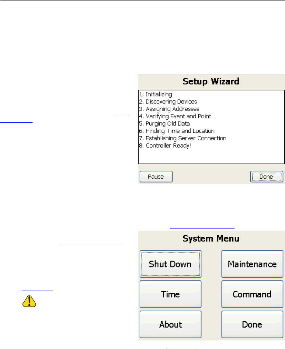
4.2 PoweringON
To power ON a controller, press the red switch on the back of the Display Mesa.
Each time a controller is powered ON, the Setup Wizard initializes the box. The first time the Setup Wizard runs, you
are prompted to enter information about the event, such as the event name, point name, and number of controllers
and Gators being used (see Point Configuration). When the controller is subsequently powered ON, if properly
configured, the Setup Wizard ensures that the proper connections are made and completes without interruption.
NOTE: When networking controllers together, the number of Controllers, Readers and Gators must be configured
during initial setup of each controller. The time and date can be set on one controller and synchronized with the
others. See Synchronizing the Time on Multiple Controllers for more information.
4.3 PreEventConfiguration
Before an event, you must configure the type of point (start, split, etc.), and set the time and date using the BoxScore
software. After configuring these items, shut down the controller and deploy it to its proper timing point. See Point
Configuration and Setting the Time and Date for more information.
4.4 Charging
Each controller contains up to six batteries. The charge on each battery is good for approximately eight hours with a
single reader (400 Series) in use, and four hours with two readers (800 Series) in use. LED lights on the controller
TPC Mesa indicate the total battery charge. The battery charge percentages are also shown on the System Status

ChronoTrackSystems,Inc.ChronoTrackUserManualControllerSetup
Issued:January2010 4‐4
screen. When the total battery charge is depleted to 10% of its capacity, the controller sends an alert (see
Acknowledging Alerts).
To charge the controller battery, use one of the following methods:
Use the power cord: Connect the power cord to the PWR jack on the Connection Mesa and power the
system ON. The controller must be powered ON in order to charge.
Use an external battery: Unplug the power cord and connect the external battery to the PWR jack. (This
method of charging is not power efficient)
To operate the controller using an auxiliary battery source, connect the DC cable to the auxiliary battery and plug it
into the AUX PWR jack on the Connection Mesa. Power the system ON.
Turn off ports that are not being used and other internal components for increased battery life. See Powering
ON/OFF Internal Components for more information.
ChronoTrackSystems,Inc.ChronoTrackUserManualUsingBoxScore
Issued:January2010 5‐1
5 UsingBoxScore
BoxScore is the software application that runs on the controllers.
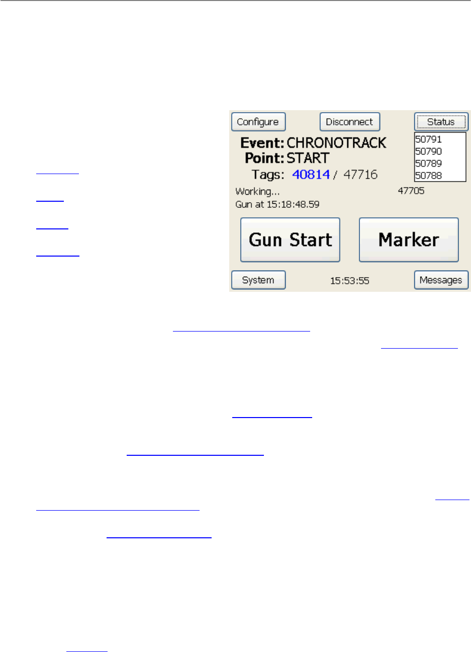
5.1 TheMainScreen
After a controller is powered ON and the Setup Wizard
completes, the main screen is displayed.
The following menus can be accessed using buttons
on each corner of the screen:
Configure menu: Used to configure settings
before an event.
Status menu: Used during an event to
display status.
System menu: Used for system maintenance
after an event.
Messages menu: Used to view and
acknowledge system alerts, and to display
gun and marker timestamps.
Other elements of the main screen include:
Connect or Disconnect: This button is used to establish a cellular, wireless, or LAN connection to the
server. When a network is connected, the button text changes to “Disconnect” and can be used to
disconnect from the network. See Establishing Network Connections for more information.
Event and Point: These fields display the event and point names as configured in the Point Configuration.
Tags: The blue count indicates the total number of unique D-Tags read by the controller. The black count
indicates the total number of tags read by the controller. (A tag is read again if a participant passes over the
same timing line beyond the five second read window, for example, if the start line is also used as the finish
line.) The box to the right of the tag count (beneath the Status button) displays up to five of the most recent
tag reads. Data is not displayed here until after the accurate time is calculated and assigned for the tag
(about five seconds). To clear the tag count, see Zeroing Tag Counts.
Network connection status: The area beneath the Tags label indicates the controller’s network connection
status. The black number next to the connection status is the total number of reads that have been passed
over the network. See Establishing Network Connections for more information.
Message line: The line below the network connection status displays messages such as the controller’s
working status, gun start times, and marker times.
Gun Start and Marker: These buttons are used during an event to set gun starts and markers. See Creating
a Gun Start Timestamp and File Markers.
System time: The current system time is displayed in the bottom center of the main screen. To change the
system time, see Setting the Time and Date.
5.1.1 CreatingaGunStartTimestampandFileMarkers
To set the Gun Start during an event, touch the Gun Start button on the BoxScore main screen. This creates a gun
start timestamp in the data files for later use in your scoring software.
To create a marker timestamp, touch the Marker button. Creating file markers helps you organize the data. When
you set a marker, data from that point on is collected in a different session.
Gun start and marker timestamps are displayed on the message line of the BoxScore main screen, and can also be
viewed from the Messages menu.
ChronoTrackSystems,Inc.ChronoTrackUserManualUsingBoxScore
Issued:January2010 5‐2
5.2 ConfigureMenu
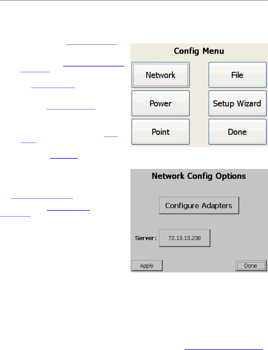
The Configure menu provides the following buttons:
Network: Used to set the server address for LAN, Wi-Fi and cellular connections and for advanced network
configurations. See Network Configuration.
Power: Used to power internal controller
components on and off for battery
conservation. See Powering ON/OFF Internal
Components.
Point: Used to configure events and points.
See Point Configuration.
File: Used to copy files from the controller to
a USB device, usually before or after an
event. See Copying Files to USB.
Setup Wizard: Used to run the Setup Wizard
to reinitialize the controller. The Setup Wizard
resets all settings to the defaults and can be
used as a troubleshooting step. See Setup
Wizard.
Done: Used to exit the Configure menu and
return to the main screen.
5.2.1 NetworkConfiguration
Network configuration options are available to set the
server address for LAN, Wi-Fi and cellular connections
(see Setting the Server Address), and to reconfigure
the IP address, netmask, and gateway for LAN and
Wi-Fi networks (see Advanced Network
Configuration). To access these options, complete the
following steps:
1. From the BoxScore main screen, touch
Configure.
2. On the Config Menu screen, touch Network.
3. When finished working with Network Config
options, touch Done.
5.2.1.1 Setting the Server
Address
In order to download controller data directly to a laptop, a network connection must be established with a server. To
set the server address, complete the following steps:
1. On the Network Config Options screen, touch the Server button.
2. Enter the IP address you wish to use as the server, Touch OK.
The Server button displays the server or IP address that you entered.
3. Touch Apply, and then touch Done.
After setting the server address, you must establish the network connection. See Establishing Network Connections
for more information.
ChronoTrackSystems,Inc.ChronoTrackUserManualUsingBoxScore
Issued:January2010 5‐3
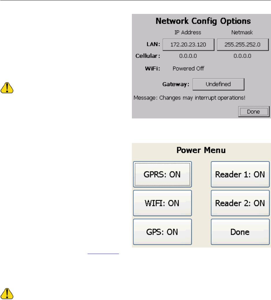
5.2.1.2 Advanced Network
Configuration
To change the IP address, netmask, and gateway for
LAN and Wi-Fi networks, click the Configure
Adapters button on the Network Config Options
screen.
Click the buttons to change the addresses and
gateway. The Cellular addresses are assigned by the
Internet service provider and are read-only.
Do not make changed here unless directed.
5.2.2 PoweringON/OFFInternal
Components
Battery power can be conserved by turning off individual controller components that are not being used. The readers
consume the most power. If you are only using four ports on an 800 Series controller, turn off the second reader to
nearly double battery life.
To power on/off internal components, complete the
following steps:
4. From the BoxScore main screen, touch
Configure.
5. On the Config Menu screen, touch Power.
On the Power Menu screen, buttons indicate
whether a component is on or off.
6. Touch the desired item to switch to the
opposite setting.
7. When finished, touch Done.
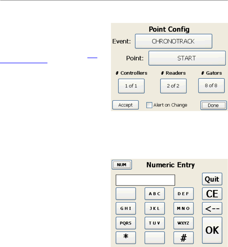
5.2.3 PointConfiguration
When you first set up a controller, the Setup Wizard
prompts you to configure the timing point by displaying the Point Config screen. Thereafter, as long as the proper
connections are made based on the configuration, the Setup Wizard continues through the point configuration. For
example, if the controller is configured as shown in the image and only four antennas are connected, the Setup
Wizard will display the Point Config screen and the # Gators box will display 4 of 8, until the other four antennas are
connected or until you touch Done.
TouchingDonewithoutproperconfigurationwillresultinreducedperformanceofthesystem.
ChronoTrackSystems,Inc.ChronoTrackUserManualUsingBoxScore
Issued:January2010 5‐4
You can make changes to the point configuration at any time. To access the Point Config screen, do the following:
1. From the BoxScore main screen, touch
Configure.
2. On the Config Menu screen, touch Point.
Buttons on the Point Config screen display the current
settings. Touch a button to name or rename an event
or point, or to specify the number of controllers,
readers, and Gators used for this event. See Point
Configuration Data Input for information about
switching between alpha and numeric text entry.
Event values should be unique per event, for example,
“NYMARATHON” or “CHICAGO5K”. Point values
should be unique based on their location, for example,
“START”, “10KSPLIT”, or “FINISH”. All controllers for
an event should have the same event name.
When Alert on Change is checked, an audible alert is
sounded and the Display Mesa flashes red lights when
the controller detects a disconnect, such as loss of
antenna or network connection.
Note: Selecting Alert on Change does not require hitting Accept.
5.2.3.1 Point Configuration Data Input
When entering values for point configuration items, you can use the Alpha Entry screen or Numeric Entry screen.
To switch between the two screens, touch the ALPHA
or NUM button in the top left corner of each screen.
When done entering text, touch OK. A blank value is
entered if there is no entry. To cancel without making
changes, touch Quit.
The Alpha Entry screen is similar to a telephone
alphabet. To select a letter that is not the first listed in
the block, you must touch that button multiple times.
For example, to enter an R, you would touch the
PQRS button three times.
ChronoTrackSystems,Inc.ChronoTrackUserManualUsingBoxScore
Issued:January2010 5‐5
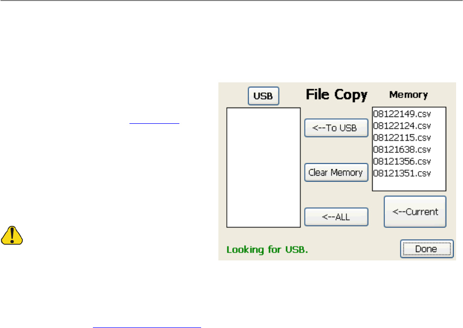
5.2.4 CopyingFilestoUSB
When a controller is powered ON, it creates and works on one data file until the box is powered OFF. If a controller is
powered ON and sees no tags during that session,
an empty file is created.
You can copy the data files from a controller to a
USB device to load the data into SimpleClient.
To copy files to a USB device, complete the
following procedure:
1. From the BoxScore main screen, touch
Configure.
2. On the Config Menu screen, touch File.
3. Insert a USB device into one of the USB 1.0
drives on the controller.
WhiletheUSB2.0Standardisbackward‐
compatiblewith1.0,notallUSBdevicesmeettheUSB
2.0standards.Werecommendtestingyourflashdrive
beforeanevent.Wealsorecommendusingthumbdriveslessthan2GB;largerdrivestakelongertoinitializeandsometimes
appeartohavecausedthesystemtolockupwhenithasnot.
4. Confirm that the status line in the lower left corner states “Ready to Copy”. If the status line does not display
“Ready to Copy” in 15 seconds, touch the USB button on the top left of the File Copy screen to reinitialize
the drive. See File Copy Status Messages for more possible status line messages.
5. When the status line indicates that the system is ready, select file(s) to copy by doing one of the following:
To copy an individual file, touch the file to copy in the Memory section, then touch To USB.
To copy all files, touch ALL.
To copy the current working file, touch Current. This function can be used during an event to
capture waves of participants. For example, if the first 100 participants have finished, you may want
to copy the current file to obtain that data immediately.
If the files are large, it can take several seconds for the file to copy. The status line on the File Copy screen
displays a count to indicate the progress.
6. When finished, touch Done. A folder is created on the USB device with a name matching the point name.
Data files are time and date stamped (MM/DD/TIME) in CSV (Comma Separated Value) format.
Files older than two weeks are erased automatically to conserve memory. To clear data files manually, touch the
Clear Memory button on the File Copy screen.
5.2.4.1 File Copy Status Messages
The following is a list of possible messages displayed on the status line of the File Copy screen:
ReadytoCopy
ErrorCopyingFile
LookingforUSB
CopyComplete
InsertUSB
CopyAllComplete
CopyinProgress
ChronoTrackSystems,Inc.ChronoTrackUserManualUsingBoxScore
Issued:January2010 5‐6
ClearinProgress
SelectItemtoCopy
ClearComplete
SystemBusy
5.2.5 SetupWizard
The Setup Wizard runs automatically each time a
controller is powered ON, performing steps to initialize
the box. The first time the Setup Wizard runs, you are
prompted to configure a point for this event. When the
controller is subsequently powered ON, the Setup
Wizard completes without any prompts as long as
connections match the point configuration. See Point
Configuration for more information.
The Setup Wizard can be run manually at any time to
reinitialize the controller as a troubleshooting step. To
run the Setup Wizard manually, do the following:
1. From the BoxScore main screen, touch
Config.
2. On the Config Menu screen, touch Setup
Wizard.
3. When done, touch Done to exit this screen.
5.3 SystemMenu
The System menu provides the following buttons:
Shut Down: Used to properly power OFF the controller. See Shutting Down the System.
Time: Used to set the time and date on the
controller. See Setting the Time and Date.
About: Displays ChronoTrack Systems
contact information and BoxScore version
information.
Maintenance: Used to “fast-charge” the
battery and to dry out the controller. See
Maintenance.
Do not touch this button during an
event. Thiswillcausethecontrollertostop
collectingdata.
Command: Used by ChronoTrack Support to
help you troubleshoot issues.
Done: Used to exit from the System Menu and return to the main screen.
5.3.1 ShuttingDowntheSystem
To properly shut down a controller, do the following:
1. From the BoxScore main screen, touch System.
2. On the System Menu, touch Shut Down.
ChronoTrackSystems,Inc.ChronoTrackUserManualUsingBoxScore
Issued:January2010 5‐7
3. On the confirmation screen, touch YES.
This procedure ensures that the proper processes are complete and the data is saved.
A hard shut-down is not recommended, but can be accomplished by pressing the power button for seven seconds.
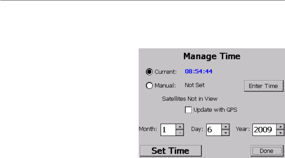
5.3.2 SettingtheTimeandDate
To set the time and date, do the following:
1. From the BoxScore main screen, touch
System.
2. On the System menu, touch Time.
3. Select one of the following three options for
setting the time:
Current: Set and synchronize the time
on networked controllers.
Manual: Set the time on this controller.
Update with GPS: Obtain the time
automatically from a GPS satellite.
4. Set the date by typing into the Month, Day,
and Year boxes or by using the up/down arrows. Setting the date is important if events run past 24 hours or
roll over to the next day during an event.
5. After setting the time and date, to exit from this screen, touch Done.
5.3.2.1 Setting the Time on a Controller
To set the time on a single controller, complete the following procedure:
1. On the Manage Time screen, touch Manual.
2. Touch the Enter Time button.
3. On the Enter Time screen, enter the correct time in [hh]:[mm]:[ss] format. Be sure to insert colons as
appropriate.
4. When done, touch OK.
5. On the Manage Time screen, make sure the date is correct or make adjustments.
6. Touch Set Time.
The Display Mesa glows red to indicate that the time is now synchronized. If the controller does not glow reset the
time.
5.3.2.2 Synchronizing the Time on Multiple Controllers
To synchronize one controller with other networked controllers, complete the following procedure on the controller
you would like to synchronize to:
1. Connect the controllers together using a network cable. (This does not need to be a crossover cable, and a
hub/switch/router is not necessary since the controllers have two network ports.)
2. On the Manage Time screen, touch Current.
3. Touch Set Time.
The Display Mesa glows red on all networked controllers to indicate that the time is now synchronized. If one
controller does not glow, check the cables to make sure they are properly connected and re-sync the time.
ChronoTrackSystems,Inc.ChronoTrackUserManualUsingBoxScore
Issued:January2010 5‐8
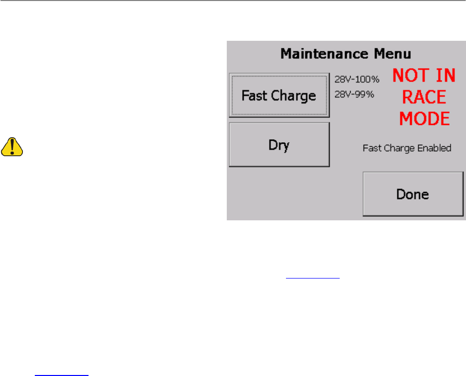
5.3.2.3 Maintenance
The Maintenance menu can be used to perform a
quick charge of the battery or to turn on fans to dry out
the controller.
To perform maintenance, do the following:
1. From the BoxScore main screen, touch
System.
2. On the System menu, touch Maintenance.
DonotenterintoMaintenanceduringanevent.
Theoperationsonthisscreencausethecontrollertostop
collectingdata.
5.3.2.4 Fast-Charging
Fast-charging is useful when you need to quickly
obtain as much power as possible, for example, when you have two back-to-back events.
To perform a fast charge, touch the Fast Charge button on the Maintenance Menu screen. This shuts down unused
components. The battery charge status is displayed next to the button.
To stop fast-charging and exit the Maintenance Menu, touch Done. The Setup Wizard runs to initialize the controller.
5.3.2.5 Dry Mode
Dry mode causes the controller to enable both readers to produce heat, and turns on fans to pump air through the
box.
To start Dry mode, touch Dry on the Maintenance Menu screen.
To stop Dry mode and exit from the Maintenance Menu, touch Done. It can take several seconds for the fans to stop,
then the Setup Wizard runs to initialize the controller.
ChronoTrackSystems,Inc.ChronoTrackUserManualUsingBoxScore
Issued:January2010 5‐9
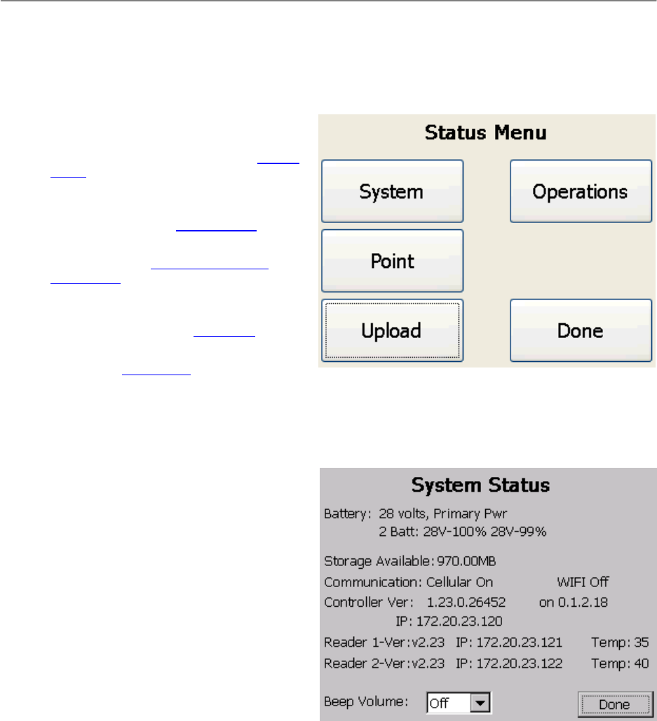
5.4 StatusMenu
The Status menu provides the following buttons:
System: Displays battery and memory
usage, version information, and other status
information about the controller. See System
Status.
Point: Used to send commands directly to a
reader and to check the status of antenna
port connections. See Reader Status.
Upload: Used to establish cellular network
connections. See Establishing Network
Connections.
Operations: Used for enabling Immediate
mode for working with live results and for
resetting tag counts. See Operations.
Done: Used to exit from the Status Menu and
return to the main screen.
5.4.1 SystemStatus
The System Status screen is used to view status information about the controller. To access this screen, do the
following:
1. From the main BoxScore screen, touch
Status.
2. On the Status Menu screen, touch System.
The information is organized as follows:
Battery: This area shows the number of
batteries and the voltage and available
charge percentage of each.
Storage Available: Displays the amount of
available memory. Each controller provides
up to one GB of storage.
Communication: Displays whether Cellular
and Wi-Fi is on or off.
Controller Ver: The top number displays the
current version of BoxScore software. The
bottom number displays the static IP address of this controller. If networked with other controllers, each
controller must use a unique static IP address.
Reader 1 and Reader 2: The first number displays the current reader version. The second number displays
the IP address of each reader. Current reader temperatures are shown to the right. One temperature is
typically higher because the readers are stacked inside the unit.
Beep Volume: This option controls whether an audible alert is sounded whenever a D-Tag is read. Select
Off for no alert, or select Low or High to enable the alert and set the volume.
To exit from the System Status screen, touch Done.
ChronoTrackSystems,Inc.ChronoTrackUserManualUsingBoxScore
Issued:January2010 5‐10
5.4.2 ReaderStatus
Using the Reader Status screen, you can send
commands directly to a reader, bypassing the
BoxScore application, and check the status of
connected antennas on each reader. To access this
screen, do the following:
1. From the BoxScore main screen, touch
Status.
2. On the Status Menu screen, touch Point.
3. When you are finished working with the
Reader Status screen, touch Done.
5.4.2.1 Sending Reader
Commands
The left side of the Reader Status screen (with the
controller image) lets you send commands directly to readers, bypassing the BoxScore application.
Donotattempttousethisfeaturewithoutadvancedknowledgeofthesecommands.Ifcontrollersarenetworked,
thesecommandsaresenttoallcontrollersandsubsequentreadersonthenetwork.
To send a command to either or both readers, do the following:
1. In the first drop-down menu, select All, Reader1, or Reader2.
2. In the second drop-down menu, select the command to send.
3. Touch Send.
5.4.2.2 Checking Connected Antennas
The right side of Reader Status screen displays a list of reader ports. This information is useful as a troubleshooting
step. When ports are connected, the status next to the port number shows OK. When ports are disconnected, the
status is displayed as “--”.
5.4.3 EstablishingNetworkConnections
Before you can send live data from a controller box to
SimpleClient on your computer, you need to establish
a network connection. There are three methods for
establishing a network connection: Cellular, Wireless,
and Wired (LAN).
The Upload Status screen is used to establish cellular
network connections. To access this screen, do the
following:
1. From the BoxScore main screen, touch
Status.
2. On the Status Menu, touch Upload.
A status message in the top right corner of the screen
indicates when a network connection has been
established. The MAC address of the controller and
connection type are also displayed.
The following buttons are available on the left side of the screen:
Power: Displays the cellular modem status. Touch the button to power the modem on or off.

ChronoTrackSystems,Inc.ChronoTrackUserManualUsingBoxScore
Issued:January2010 5‐11
Start: Starts the cellular modem when establishing a cellular connection.
Svr Cnct: Re-establishes a server connection.
Modem: Displays the Cellular screen, if the modem software is running.
The large box displays a connection log showing server activity and other details. To clear the log, touch Clear.
When you are done working with this screen, touch Done.
ChronoTrackSystems,Inc.ChronoTrackUserManualUsingBoxScore
Issued:January2010 5‐12
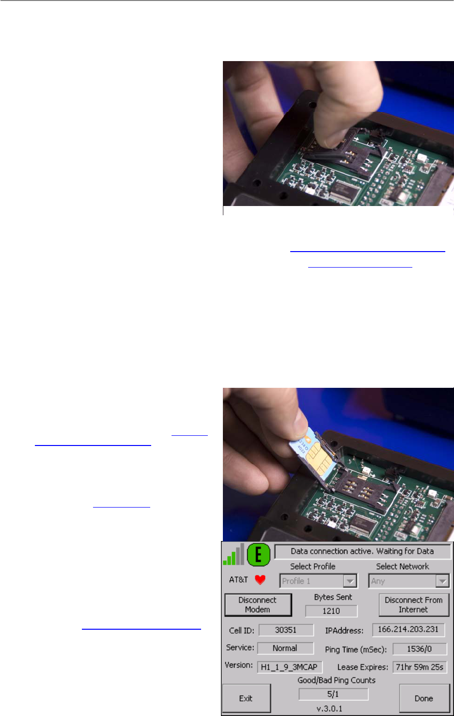
5.4.3.1 Establishing a Cellular (GPRS) Connection
To establish a cellular (GPRS) network connection,
complete the following procedure:
1. Install a SIM card in the controller. To do this,
use the following steps:
a. Unscrew the top plate to the TPC
Mesa.
b. Unlock the SIM card sleeve by
sliding it to the left.
c. Flip up the SIM card sleeve, as
shown in Figure 1.
d. Insert the card into the sleeve, as
shown in Figure 2.
e. Fold the sleeve back down into place
sliding it into the locked position and reattach the top plate.
2. Confirm that the Cellular LED is on. If not, enable the GPRS (see Powering ON/OFF Internal Components).
3. Use the Network Config Options screen to set the server address (see Setting the Server Address). Use the
ChronoTrack server by entering the IP address 72.13.13.238 (Backup: 72.13.13.239).
4. Start the modem by touching Start on the Upload Status screen.
5. On the Cellular screen (shown at right), touch Initialize Modem. Wait until the status line at the top reports
Profile activated – Connect to Internet, then touch Connect to Internet.
6. Confirm that the controller has received an IP address.
7. Return to the BoxScore main screen, and touch Connect.
5.4.3.2 Establishing a Wireless
Connection
To establish a wireless network connection, do the
following:
1. Enable Wi-Fi on the controller (see Powering
ON/OFF Internal Components). Make sure the
WIFI LED light on the controller is green.
2. Make sure your computer firewall is not
blocking port 61610.
3. Start the CCSLite bridge application on your
computer (see Using CCSLite).
<<insert screenshot>>
4. Create a wireless ad hoc network on your
local computer. Please refer to your operating
system or network card manufacturer for
instructions. The IP assigned should be
192.168.0.X (preferably between 2-99). If an
appropriate IP address is not assigned,
please manually assign an IP address in this
range. For the appropriate networking key
and SSID, please refer to the ChronoTrack
user forum (https://secure.chronotrack.com).
Fi
1
Figure2
ChronoTrackSystems,Inc.ChronoTrackUserManualUsingBoxScore
Issued:January2010 5‐13
Note that a valid ChronoTrack user account is needed to log in to the forum.
<<insert screenshot>>
5. Configure the server IP address on the controller to match the IP address of the wireless device on your
computer.
<<insert screenshot>>
6. Touch Connect on the main screen.
5.4.3.3 Establishing a Wired Connection
To establish a wired network connection using an Ethernet cable:
1. Configure the computer with a designated static IP address and subnet mask. Set the IP address to a
number in the range 172.20.23.2-99 (do not use 172.20.23.1). Set the Subnet Mask to 255.255.252.0.
Consult your operating system manufacturer for networking instructions.
<<insert screenshot>>
2. Make sure your computer firewall is not blocking port 61610.
3. Start the CCSLite bridge application on your computer (see Using CCSLite).
4. Change the server IP address on the controller to match the IP address that you set on your computer (see
Setting the Server Address).
5. Connect an Ethernet cable from the controller to your computer.
6. On the BoxScore main screen, touch Connect.
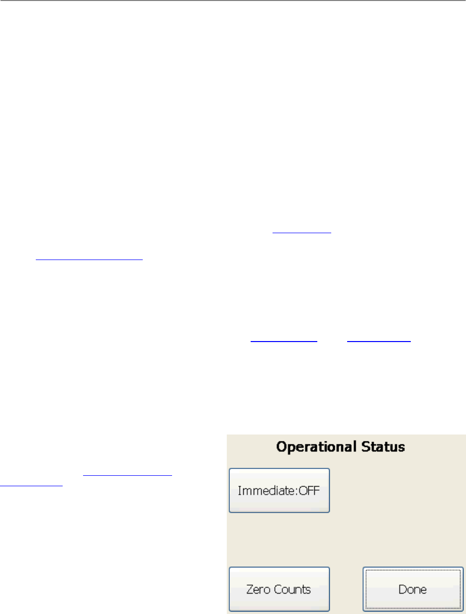
5.4.4 Operations
The Operational Status screen is used to put the controller into Immediate mode and to reset tag counts. To access
this screen, do the following:
1. From the BoxScore main screen, touch Status.
2. On the Status Menu screen, touch Operations.
3. When finished working with the Operational Status screen, touch Done.
5.4.4.1 Immediate Mode
Touch the Immediate button to work with live results
reporting for an announcer line. To create an
announcer line, you must also enable Immediate mode
in SimpleClient. See Creating and Using an
Announcer Line for more information.
NOTE: When the controller and SimpleClient are
Immediate mode, tags are only reported once despite
the number of reads.
5.4.4.2 Zeroing Tag Counts
Touch the Zero Counts button to reset the unique and
total tag count numbers that are displayed in blue and
black on the BoxScore main screen. You might want to
zero tag counts if you are using the same timing line
for a start and finish. After all participants have
crossed the start line, you can zero the tag counts in
order to have a fresh count for the finish line.
ChronoTrackSystems,Inc.ChronoTrackUserManualUsingBoxScore
Issued:January2010 5‐14
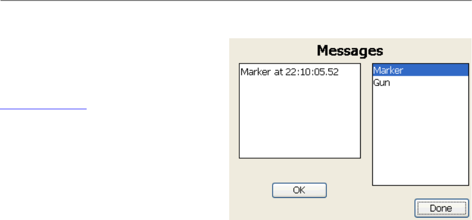
5.5 MessagesMenu
The Messages screen is used to view and
acknowledge system alerts, and to view gun and
marker timestamps. To access this screen from the
BoxScore main screen, touch Messages.
Alerts are shown in the box on the right (see
Acknowledging Alerts). To view markers or gun starts,
select the type of item to view in the box on the right.
The box on the left updates to display those
timestamps.
When finished working with the Messages screen,
touch Done.

ChronoTrackSystems,Inc.ChronoTrackUserManualUsingBoxScore
Issued:January2010 5‐15
5.5.1 AcknowledgingAlerts
Message alerts are listed in the box on the left side of the screen. To acknowledge an alert, touch OK.
The following table shows possible message alerts and meanings.
Alert Message Meaning
Readers missing The number of readers is set incorrectly. This message is displayed if the Alert
on Change option is enabled on the Point Config screen. See Point
Configuration.
Gators missing The number of Gators is configured incorrectly. This message is displayed if the
Alert on Change option is enabled on the Point Config screen. See Point
Configuration.
Primary Pwr Lost AC power is lost.
Aux Pwr Lst DC power is lost.
BATTERY CRITICAL The battery is below 10%. This message will only display once.
Y2K Problem The date and time have been reset to 1/1/2000 00:00:00.
Cell Connection Lost GPRS has lost its connection.
Bad Cell Connection This message is displayed when there are 15 consecutive poor ping responses
to the cellular network.
5.6 UpdatingBoxScore
The BoxScore software version information is listed on the About screen of the System Menu. To install a
software update on the controller, complete the following procedure:
1. Copy the update files that you receive from ChronoTrack onto a USB drive in a directory named “new”.
2. Power OFF the controller by using the proper shut-down process (see Shutting Down the System).
3. Insert the USB drive into a USB port on the controller.
4. Power ON the controller (see Powering ON).
5. During the start-up process, you will be prompted to update the BoxScore application.
ChronoTrackSystems,Inc.ChronoTrackUserManualUsingCCSLite
Issued:January2010 6‐1
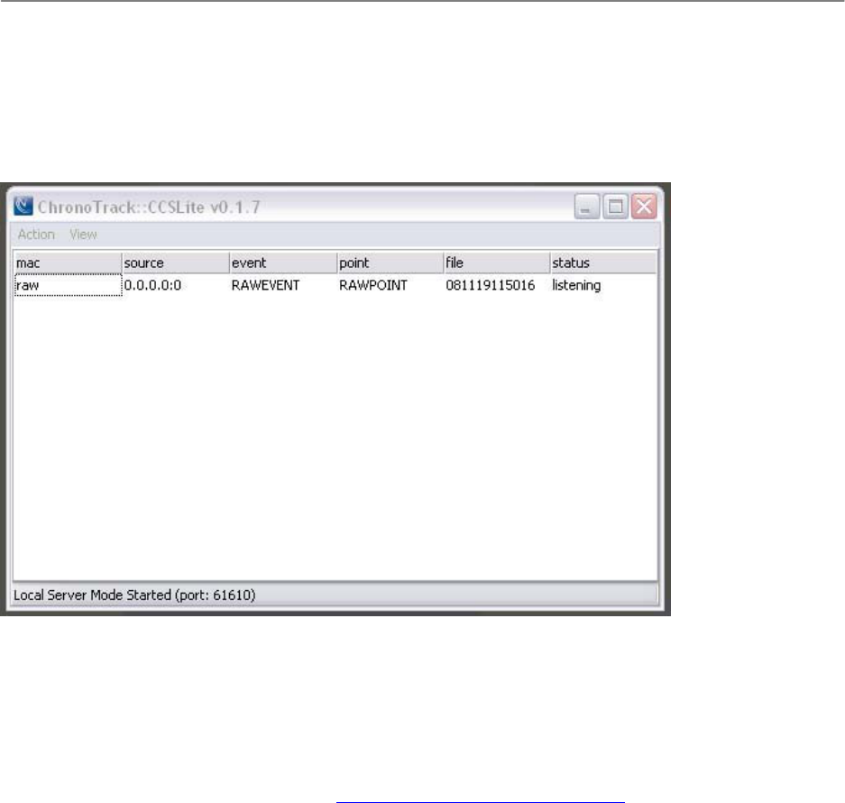
6 UsingCCSLite
CCSLite is an application that acts as a bridge between wired (LAN) and Wi-Fi network connections on the controller
and SimpleClient, an application for retrieving and manipulating controller data.
CCSLite must be running when establishing a wired or Wi-Fi network.
6.1 ConfigurationofCCSLite
To configure CCSLite, complete the following steps:
1. Start the CCSLite application on your computer.
2. Make sure Windows is not blocking TCP port 61610. When CCSLite is started for the first time, you are
prompted to choose whether or not the program is allowed to listen for incoming connections. If not, this
setting can be altered manually—see Adding a Firewall Exception for CCSLite.
3. From the menu, click Action > Storage Directory, and set the path where CCSLite will store controller data.
4. From the menu, click Action > SimpleClient Path, and select the SimpleClient executable to use when
opening data streams from the CCSLite controller grid.
5. Close CCSLite to store the settings and apply them for the next start-up of CCSLite.
6.2 EstablishingControllerConnections
To establish controller connections with CCSLite:
1. Start the CCSLite application on your computer.
2. With the controller’s BoxScore software, make a server connection to CCSLite, using the local IP address of
your computer as the server address.
3. If the controller is connected to CCSLite, you will find a new entry in CCSLite's connection grid displayed on
the main screen.
4. Double-click the entry of the controller in the CCSLite grid. This will open an instance of SimpleClient
showing you the available sessions from that controller's active file.

ChronoTrackSystems,Inc.ChronoTrackUserManualUsingCCSLite
Issued:January2010 6‐2
6.3 CCSLiteRawMode
If controllers are connected to the local network, CCSLite will listen for tag observations straight from the readers.
This is called raw mode.
This information does not contain markers (event names, point names, gun markers, and manual markers) and
BoxScore is completely ignored. However, a backup of all raw observation data on the local network is available for
use.
The raw stream also contains the information gathered from a “raw reader dump” in case of a controller lock-up. Raw
reader dumps are the final option in data recovery and should only be used if all other actions have failed. To isolate
data from the different controllers on the network, a virtual point configuration file (with .rmg extension) can be used
(see Creating Virtual Points).
6.4 AddingaFirewallExceptionforCCSLite
If you use a 3rd-party firewall, check the supplied documentation. Otherwise, complete the following steps to add a
firewall exception to Windows XP:
1. Start the security center: From the Windows Start menu, open the Control Panel and select the Security
Center menu item.
2. From the Security Center, open the Windows Firewall settings.
3. On the General tab, make sure the Don’t allow exceptions box is unchecked if the firewall is activated
(preferred).
4. On the Exceptions tab, check to see if the list box of allowed exceptions shows CCSLite. If not, unlock the
program by using either the Add Program button or the Add Port button.
NOTE: If you choose to add the program to the exception list, this port is only unlocked for the CCSLite program
started from the specified path. You will block it again if you change the path of CCSLite. Instead, add TCP port
61610 to ensure that any program attaching to that port can be reached, regardless of its program path. Also, there
may be other applications running with firewalls set (specifically programs like anti-virus, spyware protection, and ad
blockers); either disable these programs, or add exceptions for CSSLite.

ChronoTrackSystems,Inc.ChronoTrackUserManualUsingSimpleClient
Issued:January2010 7‐1
7 UsingSimpleClient
SimpleClient is an application used to retrieve and manipulate controller data. Data from events, including real-time
stats, can be filtered and streamed from SimpleClient to your computer or directly into your race scoring software.
7.1 SimpleClientOperationModes
There are two modes of operation when working with SimpleClient:
Local network mode
Internet server mode
7.1.1 LocalNetworkMode
Local network mode is used when connecting controllers through the wired (LAN) or wireless network (802.11). To
load controller files in this mode, you must either use CCSLite as a bridging application (see Using CCSLite), or load
them from a USB drive. To load from USB, use one of the following methods:
From the SimpleClient main menu, click File > Load Controller File.
Drag and drop a .mrk or .csv file onto the ChronoTrack logo on the SimpleClient main screen.
7.1.2 InternetServerMode
Controllers can send their data to the ChronoTrack CCS servers located on the Internet by using either the built-in
cellular modem or a connected router (wired LAN or wireless 802.11).
The following servers are available for North American users:
Main server: usa1.chronotrack.net (72.13.13.238)
Backup server: usa2.chronotrack.net (72.13.13.239)
The CCS Server will show sessions from all controllers and any uploaded events. This data is stored for
approximately three weeks.
To obtain data from the CCS Server online and use it on your local computer, establish a connection with the CCS
Server using your ChronoTrack user account. See Connecting to the Server and Retrieving Data for more
information.
7.2 ConnectingtotheServerandRetrievingData
You can send data from a controller into SimpleClient by connecting to the CCS Server. To connect to the CCS
Server, complete the following procedure:
1. Establish a network connection on the controller. See Establishing Network Connections.
2. Start the SimpleClient application on your computer.
3. If you want to be connected directly to your scoring software, see Establishing a Direct Socket Connection
with Scoring Software.
4. From the main menu, click CCS Server > Connect.
5. A connection box is displayed. Make sure that the box contains the following information:
Hostname:72.13.13.238orusa1.chronotrack.net
TCPPort:61612
Yourlog‐inusername
Yourpassword
ChronoTrackSystems,Inc.ChronoTrackUserManualUsingSimpleClient
Issued:January2010 7‐2
6. Click Connect.
The Select Device Session screen is displayed and you are now connected to the server with all of your
events.
7. Filter to display only your current event by unchecking All events.
8. Use the drop-down list to select the event from which you want to retrieve data.
9. Click on the segment to load, then click Select at the bottom of the screen.
The SimpleClient main screen is displayed. You can now either start streaming the data and/or save the
data for import into your software:
To start the data stream onto your computer, click Play. If you have a direct connection with your
scoring software, you will see the times in your software.
To save the data, click Play. From the main menu, click File > Save As.
10. Repeat these steps to connect to other checkpoints. Alternately, open a new session of SimpleClient to run
multiple streams at the same time.
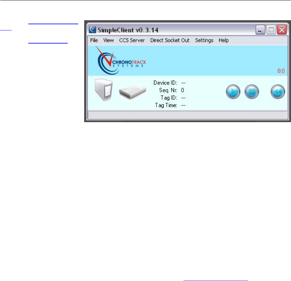
7.3 StreamingData
After selecting a file segment to stream onto your computer (see Connecting to the Server and Retrieving Data), use
the following buttons on the SimpleClient interface to start, stop, and rewind data:
Play: Starts the data stream into a buffer on your computer.
Stop: Stops the data stream. To pick up where you left off, press Play.
Rewind: Starts the data stream over from the beginning.
ChronoTrackSystems,Inc.ChronoTrackUserManualUsingSimpleClient
Issued:January2010 7‐3
As the data plays, there are two red numbers above the buttons. The first red number indicates the size of the save
buffer (see Saving SimpleClient
Data). The second indicates
the size of the invalidated tags
buffer (see Tag Invalidation).
The middle section of the
screen displays the data for
each tag as it plays.
7.4 Tag
Invalidation
Tags can be invalidated in
order to prevent them from
appearing in your race scoring
software. There are three
features that can be used to specify which tags should be invalidated:
Activated tag range filtering
Ignore same tag for X seconds
Activated invalidate negative times
To inspect tags that have been invalidated, from the SimpleClient main menu, select View > Invalidated Tags.
The screen shows all invalidated tags listed by order of arrival. The reason for invalidation of each tag is also shown.
If a tag has been invalidated in error, it can be revalidated:
1. Select the tag entries on the grid that should be revalidated.
2. Right-click and select Validate Selected.
The revalidated tags will be removed from the grid and the observations will be put at the end of the save buffer,
ready to be streamed to the race scoring software or saved to text file.
7.5 FileFormats
SimpleClient lets you export data and specify how the files are formatted (separators, line terminators, etc.). This is
useful when you need to send data to a third-party application that requires a specific file format.
To specify file formats, from the main menu, click File > File Format. See File Format Specifications in the Appendix
for information about available formats and syntax.
7.6 SavingSimpleClientData
You can manually save the current feed/buffer, or configure SimpleClient to save files automatically:
To save the current buffer in SimpleClient (as indicated by the first red number on the main screen), from the
main menu, click File > Save File.
To automatically save files, click File > Auto Save and set the path where the files should be saved. You
can then configure your scoring software to retrieve data from that path.
If you want each session that you open for a different point to be automatically saved using the point
designation as the file name, click File > Auto Save and check Single Point/File. When this option is not
checked, each stream is saved to its event designation (so you can have multiple points in a file belonging to
the same event) and uses the event designation in the file name.
When saving files, both manually and with Auto Save, the output is sent to either a text file or, if established, to a
direct socket connection, for streaming into your scoring software. A direct sockect connection is the preferred
solution with RunScore scoring software.

ChronoTrackSystems,Inc.ChronoTrackUserManualUsingSimpleClient
Issued:January2010 7‐4
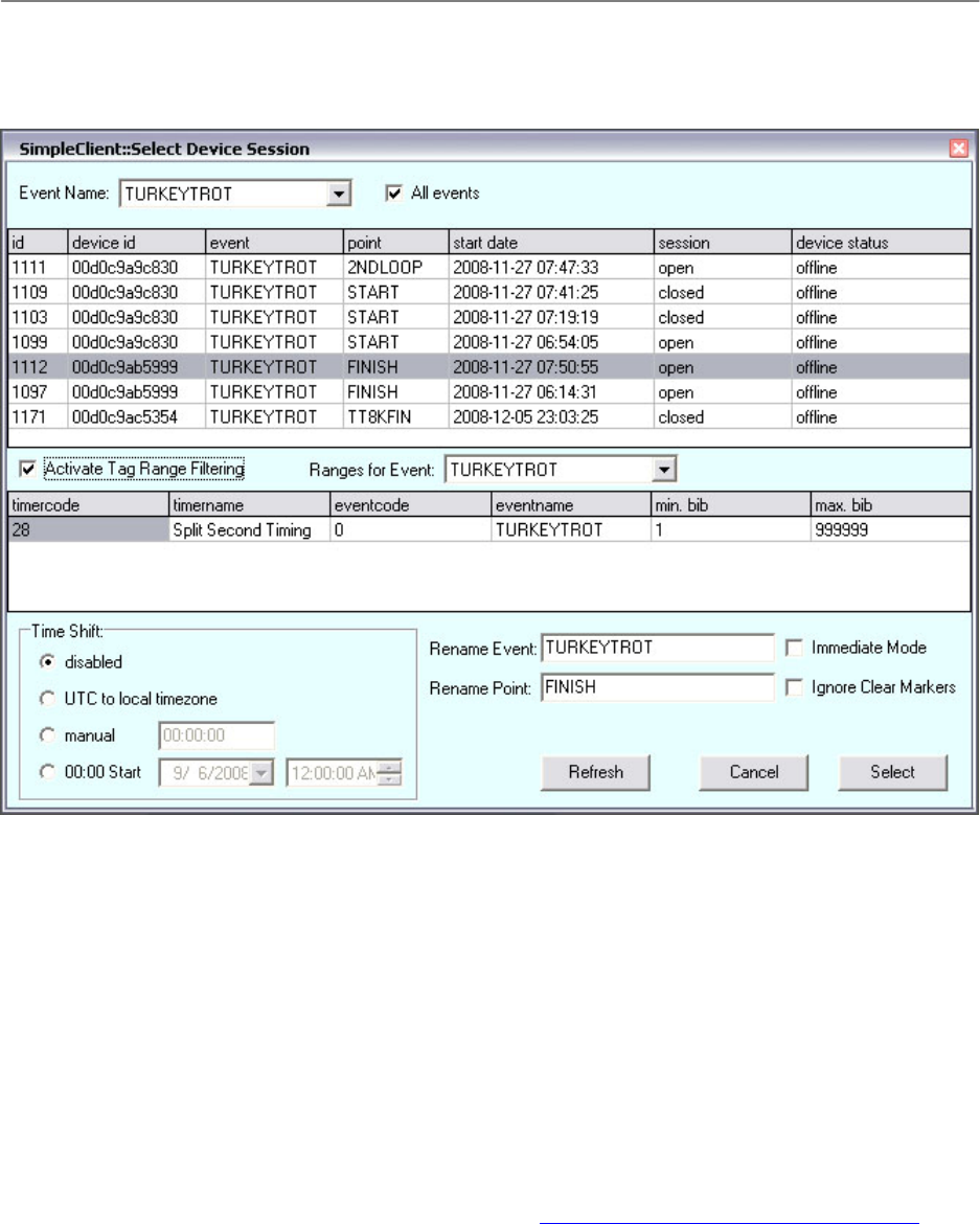
7.7 FilteringData
Filters can be applied to organize your data. You can filter out bib numbers from previous events or filter by various
segments such as leagues. Tag filters can be created online and applied in SimpleClient so that only tag data within
specified bib ranges, event codes, and/or timer codes is streamed.
The Select Session File screen in SimpleClient is used to activate tag range filters that you create online. To filter the
data shown in SimpleClient, complete the following procedure:
1. On the Select Session screen, select the point containing the data you want to filter.
2. Select the Activate Tag Range Filtering option.
3. The Tag Ranges for Event drop-down menu contains a list of tag ranges that you have created pre-event.
Select the tag ranges for your event.
4. The columns in the middle of the screen display the filtering selections of timer and event codes and names,
and minimum and maximum bib numbers. D-Tags are assigned a timer and event code when they are
printed and encoded.
7.7.1 CreatingTagRangesforanEvent
To create tag ranges for an event, complete the following procedure:
1. Prior to the event, log in to the ChronoTrack StreamManager at https://secure.chronotrack.com with your
valid ChronoTrack user account. After logging in, a Welcome page with your name is displayed.
2. Click the Manage Events heading.
3. Click Add an Event.
4. Enter the information about your event.
5. Click Submit. The page now shows the tag range you created.
6. To save the tag ranges locally to your computer, from the main menu, click CCS Server > Update Local
TagRange DB.
7.8 CreatingVirtualPoints
Some events, like triathlons, will utilize multiple points at the same location (run in, bike out). For these types of
events, it is possible either to use multiple controllers in normal mode, or to split up the points based on individual
Gators or combinations of Gators from a single controller. To split the point names, you will need to relocate point
information on your readers and Gators by creating and loading a virtual point file in Simple Client. This file specifies
which MAC addresses should be assigned to which reader and ports.
The virtual point file must be an ASCII file with an RMG file extension. The text must be semicolon-delimited with
each new point on a separate row. The syntax for each row is:
[ReaderMACAddress];[FirstGatorID];[LastGatorID];[NameOfNewPoint]
Valid Gator IDs are 1, 2, 4, and 8.
Below is an example of a virtual point file:
003487;1;1;GATOR1
003487;2;2;GATOR2
003487;4;4;GATOR3
003487;8;8;GATOR4
This example relocates each Gator to a new point name. The most common setup would be to separate both readers
and can be done like this:
003487;1;8;READER1
0034AF;1;8;READER2

ChronoTrackSystems,Inc.ChronoTrackUserManualUsingSimpleClient
Issued:January2010 7‐5
After creating the virtual point file, load it into SimpleClient with the following steps:
1. From the SimpleClient main menu, click Settings > Relocate Point Info on Reader/Gator.
2. Select Virtual Points.
3. Click Configure.
The file is now loaded and will be included in the Select Session screen, labeled “Virtual Points”.
7.9 CreatingandUsinganAnnouncerLine
Announcers can view live data about participants during an event with an announcer line. To create, load, and view
an Announcer Line, do the following:
1. Create a bib file.
A bib file is an ASCCI semicolon-delimited file with field headers. The field headers are displayed as column
headers in the announcer line. The first field header must be the bib number, but you can add as many other
fields as you like. Below is an example of the first few lines of a bib file:
BIB;FIRSTNAME;LASTNAME;AGE;SEX;CITY;DIVCODE
25;Scott;Abrams;51;M;LA PINE;G
26;Julio A;Aguirre;62;M;HIGHLAND PARK;I
27;Claus G.;Ahrens;25;M;JERSEY CITY;C
2. From the SimpleClient main menu, click File > Load Bib File and select the file you just created. This loads
the file into SimpleClient.
3. In order to view live data streaming into the Announcer Line, make sure there is a network connection with
the controller, then put the controller into Immediate mode (see Immediate Mode).
4. Enable Immediate mode in SimpleClient by selecting it from the Tag Mode drop-down list on the Select
Session screen.
NOTE: When the controller and SimpleClient are in Immediate mode, tags are only reported once despite
the number of reads.
5. From the SimpleClient main menu, click View > Announcer Display.
6. On the SimpleClient main screen, click the Play button.
You can resize the Announcer Display window to zoom text by dragging the edges.
The Flush Queue option clears the grid and can be used to help announcers keep up with participants if the
streaming data is coming in too quickly (like runners crossing a finish line). Other options are available to set the
scroll speed in seconds, change number of rows, colors, and more.
To hide tags that do not contain participant data, from the Announcer Display window, click View > Hide Unknown
Tags.
7.10 LoadingControllerFiles
After copying a file from a controller to a USB device, load it into SimpleClient by doing one of the following:
From the SimpleClient main menu, click File > Load Controller File, then select the file to load.
Drag the file onto the SimpleClient main screen.
When you load a controller file, the Select Session screen displays the event and point names. If markers exist in the
file, any tags after a marker are listed on another row.
To stream the data, select the event and point and click Select, then click the Play button on the SimpleClient main
screen.

ChronoTrackSystems,Inc.ChronoTrackUserManualUsingSimpleClient
Issued:January2010 7‐6
To connect directly to your scoring software, follow the instructions under Establishing a Direct Socket Connection
with Scoring Software. Alternately, you can save the data to a file that you can import into your scoring software by
clicking File > Save File from the main menu.
Repeat this process to import, play, and save other files that you have copied from the controller.
7.11 EstablishingaDirectSocketConnectionwithScoringSoftware
You can connect SimpleClient to your scoring software with a direct socket connection. This enables data to stream
directly into your scoring software when you start a data stream in SimpleClient.
To establish a direct socket connection, complete the following procedure:
1. Open your scoring software (for example, RunScore, Race Director, or your own software).
2. Initialize your software to allow connections from SimpleClient on port 61611.
3. Open SimpleClient.
4. On the main menu, click Direct Socket Out, and make sure Enabled and Auto Reconnect are checked.
5. Click Direct Socket Out > Connect.
A connection window is displayed showing the hostname as “local host” and the TCP port as “61611”.
6. Click Connect on the connection window.
Connecting opens the socket so that when you play data in SimpleClient, the data is also streamed directly into the
scoring application.
7.12 SettingTimeIntervalsforPassCountsandSameTagObservations
You can set the time interval for pass counts so that if the same tag is read twice within a specified time, it is not
marked as a second lap. For example, if it takes at least five minutes to complete one lap, you could set the time
interval to four minutes so that any tags read twice within four minutes are not counted.
To set the time interval from the SimpleClient main menu, click Settings > Time Interval for Pass Count.
You can also specify that the same tag should be ignored for a specified number of seconds. This is useful to prevent
the same tag from being reported twice when you have primary and backup lines. To set this option, from the main
menu, click Settings > Ignore Same Tag for … Seconds. Ignored tags are placed in the invalidated tags list (see
Tag Invalidation).
7.13 CreatingTimeShifts
If the controller time was not accurate for your needs when it was collecting data, you can adjust the time using
SimpleClient. To create a time shift, use the Time Shift set of options on the Select Session screen:
Disabled: No time shift adjustments.
UTC to local timezone: Shifts the time to match your computer’s local time.
Manual: Enables you to enter a specific time.
00:00 Start: Used to set the date and time if the time at Gun Start was a zero time.
7.13.1 Disabled
By default, tag observations are not time-shifted. Since most race scoring software cannot handle dates and the
ChronoTrack controller holds both date and time, the controller timing information needs to be converted. To allow
timing events with a duration over 24 hours, the normal output mode is in a special 24h+ format. To convert the
controller time to 24h+ format, SimpleClient introduces a concept of base dates. When a session is selected and the
stream is started, the first tag observation or gun marker (whichever comes first) is inspected. The date found in this
tag observation or gun marker is now set as the base date. Each consecutive observation or marker is inspected for
its date and compared to the base date. If the date is the same, a normal time output can be expected, ranging

ChronoTrackSystems,Inc.ChronoTrackUserManualUsingSimpleClient
Issued:January2010 7‐7
between 0:00:00.00 and 23:59:59.99. If the date found is later than the base date, the difference in days is multiplied
by 24 and added to the hours section of the time of day. If the date found is earlier than the base date, the output will
contain a negative time showing the difference between the observed time and midnight at the base date. If you do
not want to output negative times, you can disable the output of negative times from the SimpleClient Settings menu.
7.13.2 UTCtoLocalTimezone
Use this mode when you synchronize the controllers by GPS to the UTC timezone. In this mode, the difference
between UTC timezone and your computer's timezone setting will be used for a time shift, resulting in timing output
converted to local time of day. After times are shifted, SimpleClient will continue to use its base date logic.
7.13.3 Manual
If you find a controller to be off by a specific amount of time, you can use the manual option to adjust the controller's
misaligned timing. A positive offset will increase the times, while a negative offset will decrease times. After times are
shifted, SimpleClient will continue to use its base date logic.
7.13.4 00:00Start
This option can be used for multiple timing issues and is very powerful. By setting the date and time part of this
option, you pinpoint an exact moment in time on which the timing output of SimpleClient will be equal to 0:00:00.00.
The difference between a tag observation’s date and time and this zero point will be the output to your race scoring
software.
By only setting the date and keeping the time to 0:00:00, you can set the base date manually, overriding
SimpleClient's automated base date discovery in case it gives you timing errors.
By also setting the time, you can actually convert SimpleClient's output to race time instead of time of day. If you
enter both date and time equal to the gun time, you will get this behavior. If you have used a gun marker on the
controller and its timing information is displayed on SimpleClient's session form, you can drag the gun marker to the
00:00 Start Time Shift option to automatically fill it in.
7.14 RenamingEvents/Points
Events and points can be renamed in SimpleClient. On the Select Session screen, type the new names in the
Rename Event and Rename Point text boxes. When you change an event or point name in SimpleClient, the name
is relabeled in the text file output or direct socket protocol.
7.15 MoreSimpleClientFunctions
More SimpleClient functions are described below.
To view gun times, from the main menu, click View > Gun Times. This displays information about each gun
start set in the file.
To view invalidated tags, from the main menu, click View > Invalidated Tags.
If you have already loaded a session from a controller file, you can go back to the same CSV file and select
another session from it to load. To do this from the main menu, click File > Show Available Sessions. This
option is only available when working in local mode (as opposed to server mode, when you are connected to
the CCS Server).
If you are working on a session, you can close local mode and switch to a CCS Server stream without
closing Simple Client. To do this from the main menu, click File > Close Local mode.
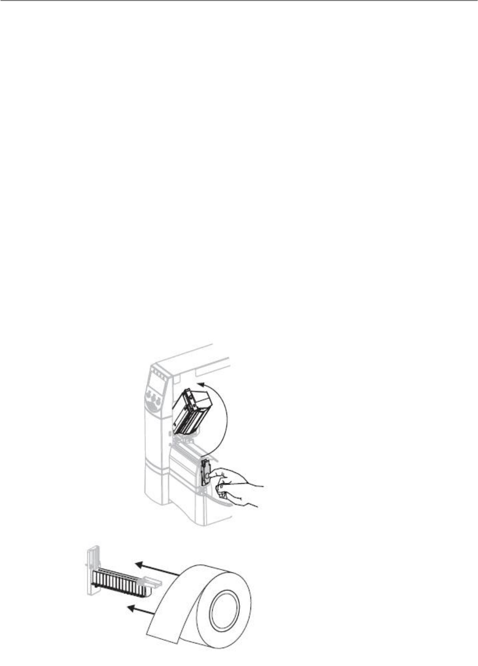
ChronoTrackSystems,Inc.ChronoTrackUserManualPrintingandRe‐encodingD‐Tags
Issued:January2010 8‐1
8 PrintingandReencodingDTags
The ChronoTrack printing system is used to print and re-encode D-Tags. It is comprised of the following hardware
and software:
Zebra RZ600 Printer
Ensyc RF2400 RFID Reader
Symbol LS 2208 Barcode Scanner
ChronoTrack PrintDTag software
Wasp Labeler 6.06 software
8.1 PrinterInstallation
Load ChronoTrack PrintDTag CD-ROM.
Copy Drivers\Zebra\ZD1452 to C:\ZD1452.
Copy Drivers\Ensyc\RF1200 to C:\RF1200 Driver
8.1.1 PrinterSetupHardware
Once printer is placed in suitable location, open lift-up cover and install labels and ribbon (see RZ600 manual for
detailed description).
Open printhead:
Load labels:
ChronoTrackSystems,Inc.ChronoTrackUserManualPrintingandRe‐encodingD‐Tags
Issued:January2010 8‐2
Load Ribbon:
Notice that labels roll off from top and ribbon rolls off the bottom. Make sure label and ribbon roll are snug against
back of printer. Also make sure label backing is flush with inner cardboard label core.
ChronoTrackSystems,Inc.ChronoTrackUserManualPrintingandRe‐encodingD‐Tags
Issued:January2010 8‐3
Close printhead:
Line leading edge of label with metal tear-off bar.
Line up ribbon with vertical line on upper guide plate (top arrow above).
Line up label backing with ride edge of “V” on tear-off bar (bottom arrow above).
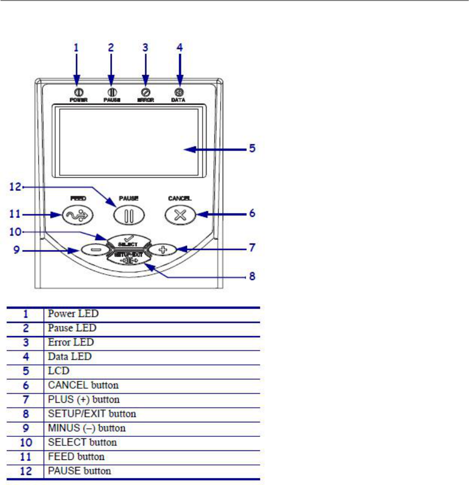
ChronoTrackSystems,Inc.ChronoTrackUserManualPrintingandRe‐encodingD‐Tags
Issued:January2010 8‐4
8.1.2 PrinterSetup–Software
Power on printer (switch in rear).
On printer control panel (see above), press Setup/Exit.
Press “+” 3 times, should display Print Mode RFID
Press Select, then press “-“ until Tear Off is displayed.
Press Select.
Press Setup/Exit – should display Permanent, press Setup/Exit again.
Press Feed to verify printer detects labels correctly.
Printer Modes Diagram:
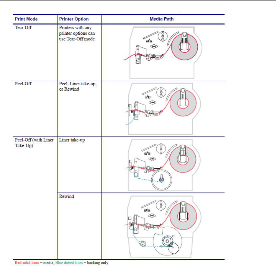
ChronoTrackSystems,Inc.ChronoTrackUserManualPrintingandRe‐encodingD‐Tags
Issued:January2010 8‐5
8.1.3 PrinterSetupWindows
Once the printer is initially powered on and setup, plug bi-directional parallel cable (preferred) or USB cable from PC
to printer. Windows will detect new hardware. The following images are from an XP Professional installation:
ChronoTrackSystems,Inc.ChronoTrackUserManualPrintingandRe‐encodingD‐Tags
Issued:January2010 8‐6
Click No for automatic update.
Click to specify location.
ChronoTrackSystems,Inc.ChronoTrackUserManualPrintingandRe‐encodingD‐Tags
Issued:January2010 8‐7
Specify C:\ZD1452 as search location.
Click Continue Anyway.
Windows may prompt for additional driver, again point to location C:\ZD1452.
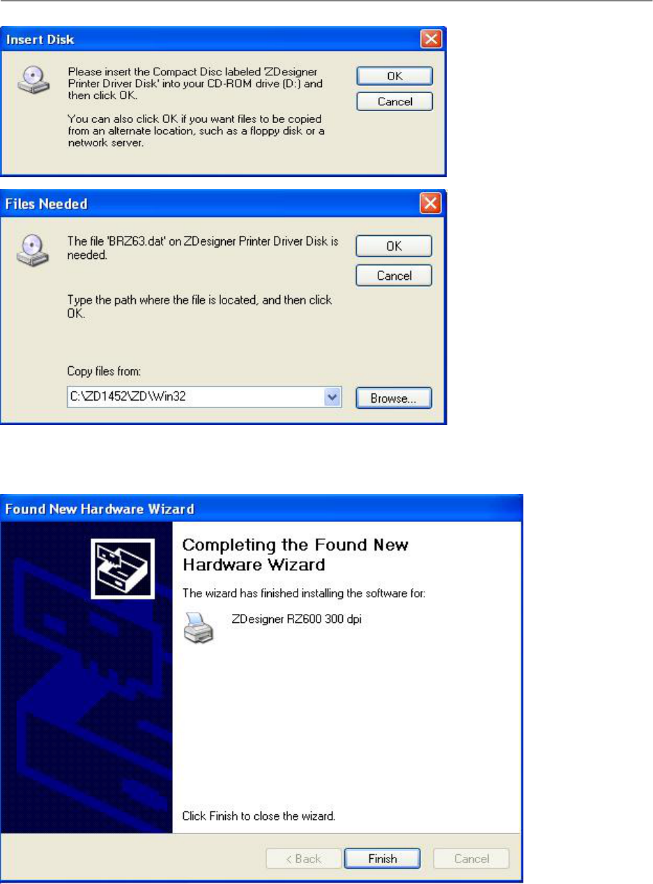
ChronoTrackSystems,Inc.ChronoTrackUserManualPrintingandRe‐encodingD‐Tags
Issued:January2010 8‐8
Last, Finish screen should appear indicating printer has been installed.
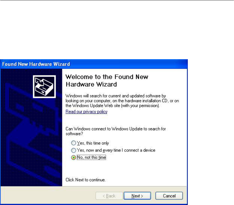
ChronoTrackSystems,Inc.ChronoTrackUserManualPrintingandRe‐encodingD‐Tags
Issued:January2010 8‐9
8.2 RFIDEncoderInstallation
Plug USB cable into RFID Encoder.
Plug USB cable into PC.
RFID Encoder should beep and PC should detect new hardware.
The following images are from an XP Professional installation:
Click No for automatic update.
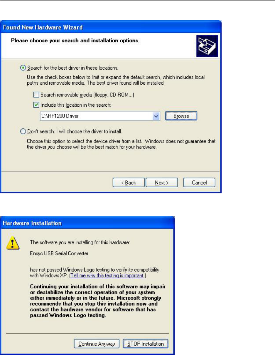
ChronoTrackSystems,Inc.ChronoTrackUserManualPrintingandRe‐encodingD‐Tags
Issued:January2010 8‐10
Specify driver location as C:\RF1200 Driver
Select Continue Anyway.
Click Finish
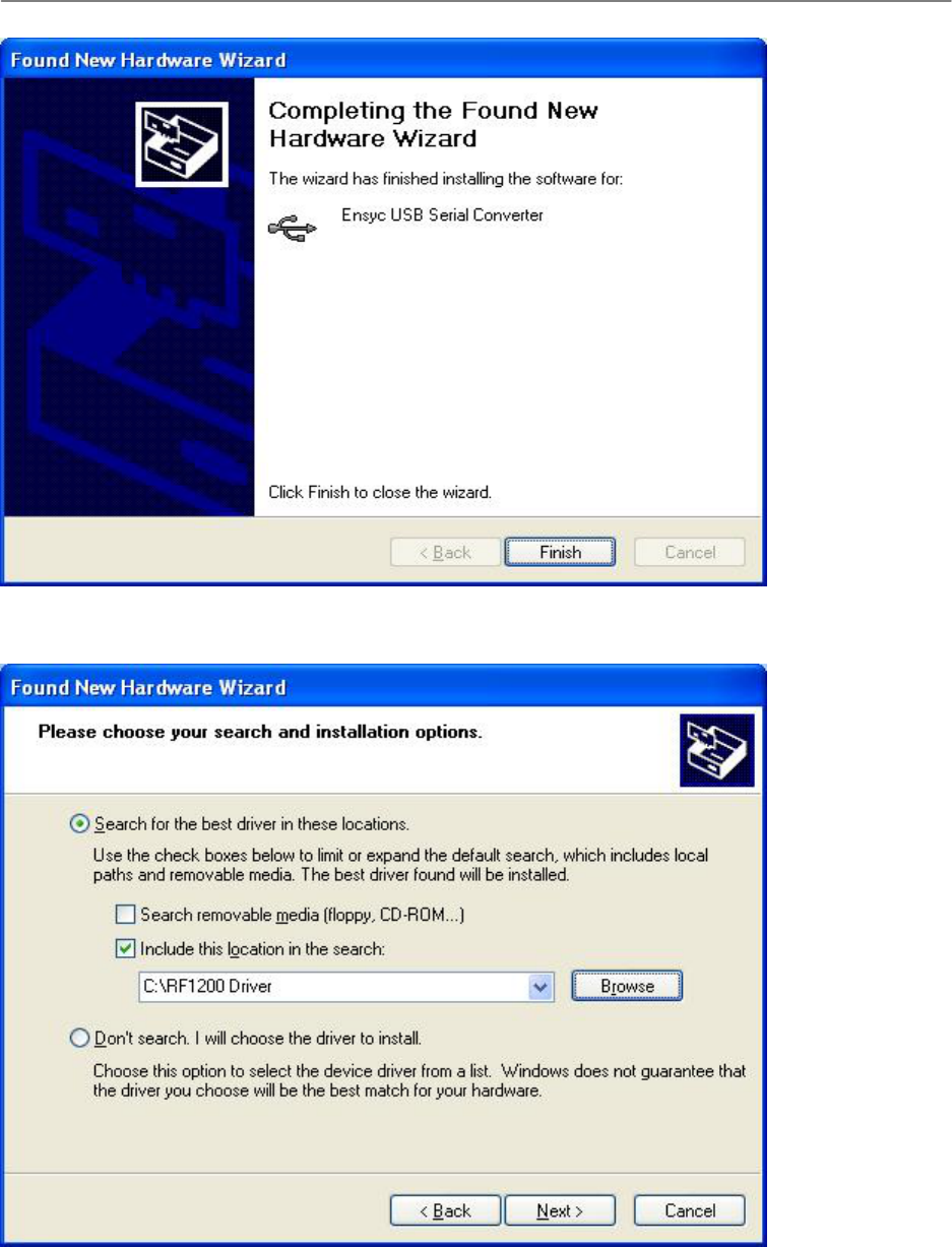
ChronoTrackSystems,Inc.ChronoTrackUserManualPrintingandRe‐encodingD‐Tags
Issued:January2010 8‐11
Windows will detect another piece of hardware. Follow same procedure as above.
Continue Anyway and then Finish Installation.
ChronoTrackSystems,Inc.ChronoTrackUserManualPrintingandRe‐encodingD‐Tags
Issued:January2010 8‐12
Message should appear that hardware is ready to use.
NOTES:
If Encoder device is not detected by PrintDTag software or if reading/writing is not working properly:
Stop PrintDTag program and unplug encoder from PC.
Reconnect encoder to PC.
Start PrintDTag program.
If problem persists, reboot PC.
8.3 BarcodeScannerInstallation
Assemble scanner stand and plug cable into handle of scanner.
Plug USB cable into PC. PC should detect hardware but not require any drivers to be installed.
Open Notepad or other text entry program and scan barcode to verify it works.
Must set post-scan character to be <ENTER>. Open scanner Quick Start Guide and scan the following
barcodes in succession:

ChronoTrackSystems,Inc.ChronoTrackUserManualPrintingandRe‐encodingD‐Tags
Issued:January2010 8‐13
Scan Options scanner beeps
<DATA> <SUFFIX> scanner beeps
ENTER scanner beeps with different tone
8.4 InstallationofSoftware
8.4.1 PrintDTagSoftware
Place CD-ROM into PC and navigate to PrintDTag folder.
Execute PrintDTag-Setup.msi. Follow install prompts; recommend installing to C:\Program
Files\ChronoTrack\PrintDTag.
8.4.2 WaspLabeler–BarcodeLabelSoftware
Place Wasp Labeler CD-ROM into PC. Again follow prompts to install. Installation requires serial number which is
on CD packaging.
Recommend using Avery 5160 size labels (1” x 2 5/8”) as these fit well with D-Tag label space.
ChronoTrackSystems,Inc.ChronoTrackUserManualPrintingandRe‐encodingD‐Tags
Issued:January2010 8‐14
8.5 PrintDTagSoftware
8.5.1 PrintDTagMainMenu
PrintDTag is the software application used to print, validate (future release), and re-encode (rewrite) D-Tags. When
you run the PrintDTag application for the first time, you are prompted to configure default settings (select Yes).
See PrintDTag Default Settings for more information.
After saving these settings, and when you start PrintDTag again, the main menu screen is displayed.
The main menu screen provides buttons to access the following operations:
Print Labels
Validate Labels
Label Rewrite
To exit the PrintDTag application, click Done on the main menu screen, or select File > Exit from the main menu.
8.5.2 PrintDTagDefaultSettings
You can change the default settings at any time by clicking the File > Default Settings menu item.
ChronoTrackSystems,Inc.ChronoTrackUserManualPrintingandRe‐encodingD‐Tags
Issued:January2010 8‐15
IMPORTANT!! When using printer for the first time, or if printer set to restore default settings, click Send Printer
Setup button. Make sure Zebra printer has been selected and saved as Primary Printer. Clicking this button sends
configuration settings to the printer. Next, click Send Printer Images button. This loads the label images to the
printer. Printer images can be loaded without printer setup.
After making changes to these settings, click Save and Quit to save changes and go to the main menu screen.
The System Settings box contains the following information:
Timer ID: The Timer ID must be a numeric value in the range 1-254. Do not use a Timer ID of 153 as this
number is used for internal tag testing of the software.
Event Code: The Event code must be a numeric value in the range 1-127.
Primary Printer: Used to specify the printer for printing the tags.
Current Row ID: Do not change—this ID is used for internal system purposes.
Debug Logging On: When checked, a debugging log named “debugfile.txt” is created and saved to the
software installation directory.
The Print Label Settings box contains the following options:
“Remove Selected…” Removes Saved Records: When checked, clicking Remove Selected Rows on
the Print Labels screen removes selected rows from the display grid and the database, so that the data is
removed permanently.
Prompt for Merge File When Printing: When checked and a participant data file is loaded, you are
prompted to merge the data when printing each D-Tag.
Prompt to Update Saved Record If Exists: When checked, if you have modified any records that were
previously saved, you are prompted to update the saved record when printing.

ChronoTrackSystems,Inc.ChronoTrackUserManualPrintingandRe‐encodingD‐Tags
Issued:January2010 8‐16
Print Labels: When checked, D-Tags are printed. If this option is not checked, you can work with database
entries without printing.
AutoFill First RFID Value: When checked, the First RFID Value entry is automatically filled with the value
used in First Label Number entry. For the majority of events, the participants’ visible number will match the
RFID number and having this setting will potentially lessen the chance of data entry errors.
Print From CSV File: When checked, all values used in printing will come from user supplied .csv file. The
default Timer ID is used, but user must enter an Event Code.
Save Data When Printing: When checked, event data is saved when you click the Save Event Data on the
Print Labels screen. A database file named “CHRONOPRINT.MDB” is created and saved to the software
installation directory. The event data can be retrieved on the Print Labels screen by selecting it from the
Event ID + Name drop-down list. If this option is not checked and you click Save Event Data on the Print
Labels screen, no data will be saved.
Make DBF File Automatically: When checked, a file named “CHRONODB.DBF” is created in the software
installation directory. This is a DBASE IV format file containing printed label information.
Do Reverse Print: Prints the tag with the last label number first, and the first label number last. This is
useful when rolling tags to make sure the correct number comes off the roll first.
Prompt To Continue Printing: When checked, printing stops after each row and you are prompted to
continue.
Label Template Value: This number (1-x) represents the label template used printing. The templates are
displayed and can be selected from Select Label Template form.
RFID AutoIncrement: When checked, after tag is successfully re-encoded, the value written is incremented
by one and this value appears in the RFID Write box. The user can then press <ENTER> or Alt +W to re-
encode the next D-Tag.
The Rewrite Settings box contains the following options:
RFID Autowrite On: This setting controls the default setting of the Write RFID After Scan option on the
Rewrite Labels screen. When Autowrite is on, every time you use the RFID Reader, the tag will be
automatically written and read. When Autowrite is off, you will need to click the Write button on the Rewrite
Labels screen to write the tag.
RFID Autowrite Delay (secs): This setting controls the default setting of the Write Delay option on the
Rewrite Labels screen. You can specify the number of seconds to wait between the RFID Reader scan and
the write operation.
ChronoTrackSystems,Inc.ChronoTrackUserManualPrintingandRe‐encodingD‐Tags
Issued:January2010 8‐17
8.5.3 PrintingDTags
Use the Print Labels screen to set up a print job and print D-Tags.
To add a new event and set up a print job, complete the following procedure:
1. Enter the new Event Name, then click New Event. The Event ID + Name field shows the saved event code
and name. The default Timer ID and Event Code are configured in the Default Settings.
Event names that you type in the Event Name box are remembered if the default setting Save Data When
Printing is checked, and will be available in the Event ID + Name drop-down for setting up future print jobs.
2. On the first row, set the Label Prefix. This is a single alpha character that does not get coded into the D-
Tag; it just prints on the tag and can be used as an identifier. For example, if you have a women’s category,
the label prefix could be “W”.
3. Set the First and Last Label Number. The first label number cannot be higher than the second. The label
numbers can be the same if you just need to print one for testing. The last label number cannot exceed
100,000. The label number ranges must be unique on each row.
If you are printing tags for different segments, like a women’s segment and a men’s segment, you could set
the label ranges on the first row to be 1-10 with a “W” prefix for women, and set the label ranges on the
second row to be 20-30 with a “M” prefix for men.
4. Set the First RFID Value. This is the value encoded on the first label and is incremented for each label
printed. RFID values cannot exceed 100,000.
If AutoFill First RFID Value is selected in the Default Settings, the First RFID Value entry is
automatically filled with the value used in First Label Number entry.

ChronoTrackSystems,Inc.ChronoTrackUserManualPrintingandRe‐encodingD‐Tags
Issued:January2010 8‐18
5. Set the # Copies. Multiples of the same tag can be printed for events such as a relays.
6. Click Load Participant Data File. This is a comma-delimited (CSV) file that you can create (similar to
creating an announcer line file). The first entry or column of each line must be the bib number. The label
image on the screen illustrates where the fields will be printed. The status line indicates if a participant data
file has been loaded.
Example .csv file:
1,Joy,Worth, F35,Murray Striders ,"Murray,KY”
2,John,Adams,M55,Berea Bulldogs,"Berea,KY”
7. If Print From CSV File? is checked, participant data must be loaded from CSV file. The data from the CSV
file is used to determine the label number, RFID number and label printing order. The Event Label
Information area is disabled when printing from CSV file.
8. Select the row(s) to print, then click Print.
9. To save the print job, select the rows to save by placing a check in the Select column, then click Save
Event Data.
This creates a database file that you can bring back up using the Reload Event button. The Save Data
When Printing setting must be checked in order to save event data.
You can remove a selected row or rows from the grid display by clicking Remove Selected Rows. If the “Remove
Selected…” Removes Saved Records setting is checked, these rows are also removed from the database and can
never be retrieved.
To just remove the rows from the grid display, click Clear All Rows.
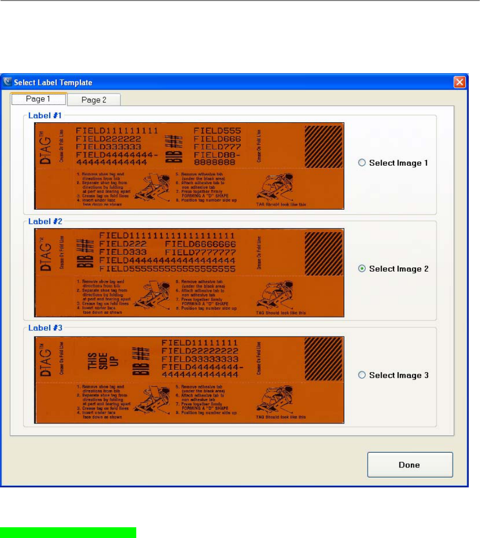
ChronoTrackSystems,Inc.ChronoTrackUserManualPrintingandRe‐encodingD‐Tags
Issued:January2010 8‐19
Select Label Template – Click this button to view or change the template used in label text layout. Templates can
be added as a user request, but will currently require a new software release. Click Done to save and return to Print
Labels.
NOTE: Multiple tabs contain other templates.
8.5.4 ValidatingDTags
Documentation to be added later.
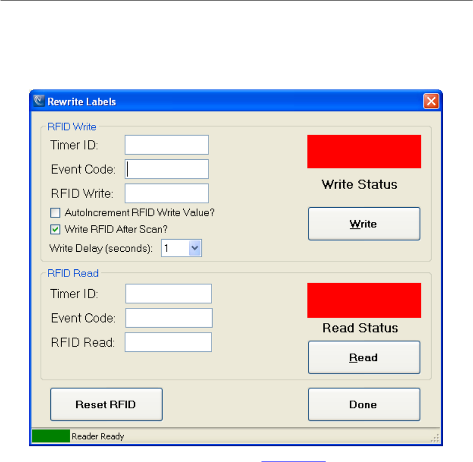
ChronoTrackSystems,Inc.ChronoTrackUserManualPrintingandRe‐encodingD‐Tags
Issued:January2010 8‐20
8.5.5 ReencodingDTags
You can rewrite the RFID encoding on leftover tags from one event so that they can be used for a new event. Wasp
Labeler 6.06 software is provided for printing new barcode labels for these tags for quick scanning. Use the
PrintDTag Rewrite Labels screen along with the RFID Reader and Barcode Scanner to re-encode the tag RFIDs.
The Timer ID and Event Code are displayed as configured in the Default Settings. You can change the Timer ID and
Event Code here; however, these changes will not be remembered.
There are two methods for re-encoding a tag: with a scanner and barcoded labels applied to D-Tags, or with no
scanner.
To re-encode a tag using a scanner and barcoded D-Tags, complete the following steps:
1. Make sure that the Write RFID After Scan option is checked and the cursor is in the RFID Value field.
2. Scan the barcode on the D-Tag.
3. Hold the D-Tag over the center of the RFID Reader, approximately 1/2 inch above surface.
4. The system will attempt to write the RFID after the number of seconds specified in the Write Delay
(seconds) box.
5. The status line at the bottom of the screen indicates the tag read/write success or failure.
If the write was successful, the Write Status and Read Status areas will turn green and a success
tone will sound. The Timer ID, Event Code, and RFID Value fields in the RFID Read section will
be populated with the values written to the D-Tag.
If the write failed, an error tone will sound and the status boxes will remain red.

ChronoTrackSystems,Inc.ChronoTrackUserManualPrintingandRe‐encodingD‐Tags
Issued:January2010 8‐21
6. When you are finished rewriting tags, click Done.
To re-encode a tag without using a scanner, complete the following steps:
1. Type the RFID number into the RFID Value field in the RFID Write section, then click Write.
2. Hold the D-Tag over the center of the RFID Reader, approximately 1/2 inch above surface.
3. The status line at the bottom of the screen indicates the tag read/write success or failure.
If the write was successful, the Write Status and Read Status areas will turn green and a success
tone will sound. The Timer ID, Event Code, and RFID Value fields in the RFID Read section will
be populated with the values written to the D-Tag.
If the write failed, an error tone will sound and the status boxes will remain red.
4. Confirm that RFID Read values for Timer ID, Event Code, and RFID Value match the information in RFID
Write section.
5. When you are finished rewriting tags, click Done.
If AutoIncrement RFID Write Value? is checked, once a D-Tag is successfully re-encoded, the value written is
automatically incremented by 1 and appears in the RFID Write field. To re-encode the next D-Tag, press <ENTER>
or Alt + W.
If you make a mistake or need to start over, click Reset RFID to stop and reset the event handler.
If problems persist, close the PrintDTag program, unplug the USB cable from the RFID Reader, and wait 10 seconds.
Plug the USB cable back into the RFID Reader (wait for beep) and restart the PrintDTag program.
8.5.6 ReadingDTags
To determine the Timer ID, Event Code, and RFID Value for a tag, open the Rewrite Labels screen. Place the tag
over the RFID Reader, then click Read. Tag data is displayed in the RFID Read group box. A read can also be done
by pressing Alt + R on the keyboard.

ChronoTrackSystems,Inc.ChronoTrackUserManualTroubleshooting
Issued:January2010 9‐1
9 Troubleshooting
The following table lists issues that might arise when using the ChronoTrack system, and provides steps for
troubleshooting.
Issue Steps to Resolution
Controller will not charge 1. Check that the unit is powered ON.
2. Confirm that the power supply LED is
green.
3. If the LED is not green, unplug the cable
connecting the power supply to the
connection mesa, then unplug and replug
the AC cable.
4. Confirm the power supply LED is now
green. If so, reconnect the cable from the
power supply to the connection mesa.
Controller will not connect to CCSLite 1. Disable all firewalls on the PC.
2. Make sure that the PC IP address is in the
range 172.20.23.2-99.
Antenna will not report connected on controller 1. Use the Reader Status screen (Status >
Point) to confirm disconnection.
2. Check the cable connections at controller
and antenna.
3. Swap ports to confirm working antenna and
cables.

ChronoTrackSystems,Inc.ChronoTrackUserManualAppendix
Issued:January2010 10‐1
10 Appendix
10.1 SystemSpecifications
DOTregulationsprohibittheshippingoflithiumbatteriesbyaircraftorvessel.Shippedcontrollersmustincludethe
followinglabel:“LITHIUMBATTERIES:FORBIDDENFORTRANSPORTABOARDAIRCRAFTANDVESSEL”.
Component Specification
D-Tag Interrogator (“Gator”)
ADA‐compliant
Physicaldimensions:42”(L)x31.5”(W)x1”(H)
ChronoTrack Controller
400Seriesprovidesfourports
800Seriesprovideseightports
Four,eight,and12‐hourbatteryconfigurations
3.5”QVGATFTLCDXScaleTouchPanel
Computer
IntelPXA270Processor
WindowsCEandBoxScoresoftware
802.11a/b/g
GSM
TwopoweredUSBports
TwoLANports
LEDsystemstatusindicators
Buzzer
110vpowerconnection
Physicaldimensions:19”(L)x14.5”(W)x7.62”(H)
Cable Sets (Short/Long)
Belden7808R
BNC‐MaletoBNC‐Male
Shortsetforconnectingupto14feetoflinked
Gators
Longsetforconnectingupto14‐28feetof
linkedGators
AC Power Cable
3‐pronggroundedmaleplug(NEMA5‐15)to3‐
pinshroudfemale(IEC‐320C13)
14’AWG18/3
SJT
DC Cable
KyconKPPX‐4P
10.2 FileFormatSpecifications
ChronoTrack offers file format flexibility. By use of a file format indicator available in the first seven bytes of a file line,
it is easy to distinguish a ChronoTrack file from other files and determine the file format and layout.

ChronoTrackSystems,Inc.ChronoTrackUserManualAppendix
Issued:January2010 10‐2
10.2.1 AvailableFields
Field Data Type Comment
file format indicator string 7 chars fixed Describes file format field separator, line
termination, and line size (see syntax described
below)
sequence number unsigned integer (max. 6
digits) Range: 1-999999
Location string max. 16 characters Invalid chars: , ; ~ | <tab> <null> since they can
be used as field terminator
Tag string max. 8 characters With ChronoTrack Systems, tag code is same as
bib number
Time string 11-12 chars 24-hour enhanced output:
0-24h: 08:19:28:84 (11 chars)
24+: 102:12:32:37 (12 chars)
lap count unsigned integer (max. 3
digits) Range: 1-999
reader id hex string 6 chars fixed NIC-specific part (4-6th octet) of MAC address
from internal reader
gator number unsigned integer (max. 2
digits) Line segment identification must be done by using
a combination of reader ID and Gator number
10.2.2 FileFormatIndicator
The file format indicator makes it easy to automatically identify a ChronoTrack file and its formatting. It is up to third-
party software to use this formatting logic or to implement a single file format. If a single format is implemented, it is
best to implement the default format (CT01_13) which uses variable width lines, comma-delimited field separators,
and <Cr><Lf> windows-style line termination.
Syntax:
CT<2-digit format number>_<2-digit format setting>
Example:
CT01_13
Comment:
This document describes format number 01. In the future, other formats may become available if
new technologies or functionalities become available. Format setting 13, which uses variable width
lines, comma-delimited field separators, and <Cr><Lf> windows-style line termination, is the default
setting in ChronoTrack.
The 2-digit format setting is used by a file parser to identify field termination, line termination, and fixed or variable line
width. It contains two nibbles (O-F) where the first (highest) nibble defines the field separator and the second nibble
the line termination and width-mode.

ChronoTrackSystems,Inc.ChronoTrackUserManualAppendix
Issued:January2010 10‐3
The following field separator options are available:
Nibble Value Separator Comment
0 <none> No separator (only available in fixed width mode)
1 , Comma
2 ; Semicolon
3 ~ Tilde, also used as separator in the socket protocol
4 | Pipe
5 <tab> Tab
6 <space> Only available in fixed width mode
The second nibble can be calculated from the following bit options:
Bit Option
1 <Cr>
2 <Lf>
3 <null>
4 fixed width mode

ChronoTrackSystems,Inc.ChronoTrackUserManualAppendix
Issued:January2010 10‐4
Using the bit-option table, the following nibble values can be calculated:
Nibble
Value Terminator Width Mode Comment
0 - - Not available
1 <Cr> Variable Carriage return \r
Mac OS 9-style line termination
2 <Lf> Variable Line feed \n
UNIX/BSD-style line termination
3 <Cr><Lf> Variable Carriage return + line feed \r\n
MS Windows-style line termination and preferred line
termination for Internet protocols
4 <null> Variable Null character \0
C-style string termination
5 <Cr><null> variable
6 <Lf><null> Variable
7 <Cr><Lf><null> Variable
8 <none> Fixed No line terminators; calculates fields and lines by size of
fixed width fields and, if used, the amount of field
separators.
9 <Cr> Fixed
A <Lf> Fixed
B <Cr><Lf> Fixed
C <null> Fixed
D <Cr><null> Fixed
E <Lf><null> Fixed
F <Cr><Lf><null> Fixed
Examples:
Format description:
CT01_13 = Variable width, comma-delimited, carriage return + line feed terminated
Example:
CT01_13,1,start,12,06:08:32.02,1,0FA22E,4<Cr><Lf>
CT01_13,2,start,69,06:38:31.86,1,04BE82,2<Cr><Lf>
Format description:

ChronoTrackSystems,Inc.ChronoTrackUserManualAppendix
Issued:January2010 10‐5
CT01_0C = Fixed width, no field delimiter, null terminated
Example:
CT01_0C 1start 12 06:08:32.02 10FA22E 4<null>
CT01_0C 2start 69 06:38:31.86 104BE82 2<null>
10.2.3 FixedWidthSizeConsiderations
A default line without field separators and without a line terminator is 60 characters wide. If a field separator is used,
the size increases by 7 (field count -1) to 67 characters. Line termination adds one to three bytes depending on the
termination used. This allows the following line sizes.
Format Settings Line Size Comment
CT01_08 60 No field separators
No line terminators
CT01_09
CT01_0A
CT01_0C 61 No field separators
Single byte line terminators
CT01_0B
CT01_0D
CT01_0E 62 No field separators
Double byte line terminators
CT01_0F 63 No field separators
Triple byte line terminators
CT01_18 – CT01_68 67 Field separators
No line terminators
CT01_19 – CT01_69
CT01_1A – CT01_6A
CT01_1C – CT01_6C 68 Field separators
Single byte line terminators
CT01_1B – CT01_6B
CT01_1D – CT01_6D
CT01_1E – CT01_6E 69 Field separators
Double byte line terminators
CT01_1F – CT01_6F 70 Field separators
Triple byte line terminators

ChronoTrackSystems,Inc.ChronoTrackUserManualIndex
Issued:January2010
11 Index
acknowledge alerts, 5-17
Alert on Change, 5-5
announcer line, 7-6
antennas
connecting, 3-3
checking connection, 5-13
Auto Save, 7-4
auxiliary battery, 4-4
bib file, 7-6
BoxScore, 5-1
updating, 5-17
CCSLite, 6-1
configuration, 6-1
controller connections, 6-2
firewall, 6-2
raw mode, 6-2
cellular connection, 5-14
charging, 4-4
clear connection log, 5-13
Config menu, 5-2
Controller
charging, 4-4
interface, 4-2
setup, 4-1
copy files, 5-6
dead zone, 3-3
direct socket, 7-7
Dry mode, 5-10
fast-charging, 5-10
file format specs, 10-1
file formats, 7-4
filter data, 7-4
firewall exceptions, 6-2
Gator setup, 3-1
GPS time, 5-9
gun start, 5-2
Immediate mode, 5-16
Internet server mode, 7-1
invalidated tags, 7-3, 7-10
LAN connection, 5-15
LEDs, 4-3
linking Gators, 3-3
load controller files, 7-7
local network mode, 7-1
Maintenance Menu, 5-10
marker, 5-2
memory, 5-11
Messages Menu, 5-16
networking controllers, 4-3
Numeric Entry screen, 5-5
Operational Status, 5-15
participant data file, 8-19
play, 7-3
Point Configuration, 5-4
power OFF, 5-8
internal components, 5-4
power ON, 4-3
internal components, 5-4
pre-event config, 4-4
PrintDTag, 8-14
settings, 8-15
printing D-Tags, 8-18
printing system, 8-1
raw mode, 6-2
read tag data, 8-22
reader commands, 5-12
Reader Status, 5-12
re-encode D-Tag, 8-21
rename event, 7-9
rename point, 7-9
rewind, 7-3
RFID readers, 4-1
save print job, 8-19
saving files, 7-4
server address, 5-3
Setup Wizard, 5-7
shutting down, 5-8
SimpleClient, 7-1
Internet server mode, 7-1
local network mode, 7-1
server connection, 7-1
Status Menu, 5-11
stop, 7-3
streaming data, 7-3
synchronizing time, 5-9
System Menu, 5-7
system specifications, 10-1
System Status screen, 5-11
tag ranges, 7-5
time and date, 5-8
time interval, 7-8
time shifts, 7-8
troubleshooting, 9-1
Upload Status screen, 5-13
USB (copy files), 5-6
view gun times, 7-9
virtual points, 7-5
wired (LAN) connection, 5-15
wireless connection, 5-15
zero counts, 5-16

ChronoTrackSystems,Inc.ChronoTrackUserManualIndex
Issued:January2010