Cisco Linksys WSB24-1 Wireless Router with Booster User Manual users manual 1
Cisco-Linksys, LLC Wireless Router with Booster users manual 1
Contents
- 1. users manual 1
- 2. users manual 2
users manual 1
WWW. LINKS YS . C O M
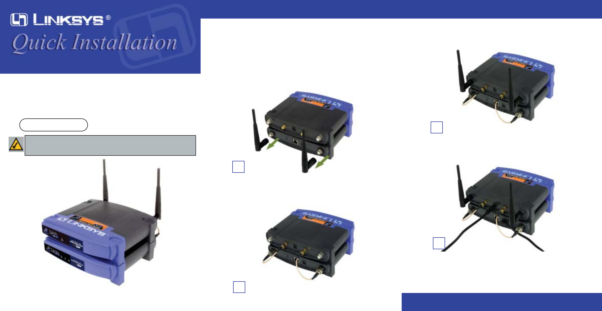
A. With your Access Point/Router powered off, place the Wireless Signal
Booster on top of the Access Point/Router.
B. Disconnect the Access Point’s/Router’s antennas.
C. Connect the Signal Booster Cables from the Access Point’s/Router’s anten-
na ports to the Wireless Signal Booster’s cable ports.
D. Connect the antennas to the Wireless Signal Booster’s antenna ports.
E. Connect the appropriate power adapters to both the Access Point/Router
and Wireless Signal Booster.
F. Now you are ready to use the Wireless Signal Booster in your wireless
network.
Connecting the Wireless Signal Booster to
Your Linksys Access Point/Router
QI-WSB24-10/25/02NC BW
B
Package Contents
• One Linksys Wireless Signal Booster
• Two Signal Booster Cables
• Two Power Adapters
• One Quick Installation and User Guide
• One Wireless Router, BEFW11S4
Wireless Signal
Booster
Instant Wireless®
WSB24-1
The Wireless Signal Booster with Access Point C
D
E
Note: The images in this document show the Wireless Signal Booster being con-
nected to an Access Point; the same directions can be followed when connecting the
Wireless Signal Booster to a wireless Router.
wsb24 quick install-2.qxd 2002/12/20 ¤U¤È 04:07 Page 1

COPYRIGHT & TRADEMARKS
Copyright c 2002 Linksys, All Rights Reserved. All other trademarks and brand
names are the property of their respective proprietors.
LIMITED WARRANTY
Linksys guarantees that every Wireless Signal Booster WSB24-1 is free from physi-
cal defects in material and workmanship under normal use for one years from the
date of purchase. If the product proves defective during this warranty period, call
Linksys Customer Support in order to obtain a Return Authorization Number. BE
SURE TO HAVE YOUR PROOF OF PURCHASE ON HAND WHEN CALLING.
RETURN REQUESTS CANNOT BE PROCESSED WITHOUT PROOF OF PUR-
CHASE. When returning a product, mark the Return Authorization Number clearly
on the outside of the package and include a copy of your original proof of purchase.
All customers outside of the United States of America and Canada shall be held
responsible for shipping and handling charges.
IN NO EVENT SHALL LINKSYS’ LIABILITY EXCEED THE PRICE PAID FOR THE
PRODUCT FROM DEFECT, INDIRECT, SPECIAL, INCIDENTAL, OR CONSE-
QUENTIAL DAMAGES RESULTING FROM THE USE OF THE PRODUCT, ITS
ACCOMPANYING SOFTWARE, OR ITS DOCUMENTATION. LINKSYS DOES NOT
ISSUE REFUNDS. WARRANTY DOES NOT COVER NATURAL DISASTERS OR
ACTS OF NATURE.
Linksys makes no warranty or representation, expressed, implied, or statutory, with
respect to its products or the contents use of this documentation and all accompany-
ing software, and specially disclaims its quality, performance, merchantability, or fit-
ness for any particular purpose. Linksys reserves the right to revise or update its
products, software, or documentation without obligation to notify any individual or
entity. Please direct all inquiries to :
Linksys P.O.Box 18558, Irvine, CA 92623
CAUTION : ANY CHANGES OR MODIFICATIONS NOT EXPRESSLY APPROVED
IN THIS MANUAL COULD VOID YOUR AUTHORIZATION TO USE
THIS DEVICE.
This device should be operated
at least 2.0m away from any person
FCC STATEMENT
The Wireless Signal Booster WSB24-1 has been tested and found to comply with
the limits for a class B digital device, pursuant to part 15 of the FCC Rules. These
limits are designed to provide reasonable protection against harmful interference in a
residential installation.
This equipment generates, uses and can radiate radio frequency energy and, if not
installed and used in accordance with the instructions, may cause harmful interfer-
ence to radio communications. However, there is no guarantee that interference will
not occur in a particular installation. If this equipment does cause harmful interfer-
ence to radio or television reception, which can be determined by turning the equip-
ment off and on, the user is encouraged to try to correct the interference by one or
more of the following measures:
—-Reorient or relocate the receiving antenna.
—-Increase the separation between the equipment and receiver.
—-Connect the equipment into an outlet on a circuit different from that to which the
receiver is connected.
—-Consult the dealer or an experienced radio/TV technician for help.
Regulatory information / Disclaimers
Installation and use of this Wireless LAN device must be in strict accordance with
the instructions included in the user documentation provided with the product. Any
changes or modifications (including the antennas) made to this device that are not
expressly approved by the manufacturer may void the user’s authority to operate
the equipment. The manufacturer is not responsible for any radio or television inter-
ference caused by unauthorized modification of this device, or the substitution of the
connecting cables and equipment other than manufacturer specified. It is the respon-
sibility of the user to correct any interference caused by such unauthorized modifica-
tion, substitution or attachment. Manufacturer and its authorized resellers or distribu-
tors will assume no liability for any damage or violation of government regulations
arising from failing to comply with these guidelines.
CAUTION: To maintain compliance with FCC’sRF exposure guidelines, this
equipment should be installed and operated with minimum distance
20cm between the radiator and your body. Use on the supplied
antenna. Unauthorized antenna, modification, or attachments could
damage the transmitter and may violate FCC regulations.
MPE Statement (Safety Information)
Your device contains a low power transmitter. When device is transmitted it sends
out Radio Frequency (RF) signal.
Safety Information
In order to maintain compliance with the FCC RF exposure guidelines, this equip-
ment should be installed and operated with minimum distance 20cm between the
radiator and your body.
Use only with supplied antenna. Unauthorized antenna, modification, or attachments
could damage the transmitter and may violate FCC regulations.
Caution Statement of the FCC Radio Frequency
Exposure
This Wireless LAN radio device has been evaluated under FCC Bulletin OET 65C
and found compliant to the requirements as set forth in CFR 47 Sections 2.1091,
2.1093, and 15.247(b)(4) addressing RF Exposure from radio frequency devices.
The radiation output power of this Wireless LAN device is far below the FCC radio
frequency exposure limits. Nevertheless, this device shall be used in such a manner
that the potential for human contact during normal operation-as a mobile or portable
device but use in a body-worn way is strictly prohibit. When using this device, a cer-
tain separation distance between antenna and nearby persons has to be kept to
ensure RF exposure compliance. In order to comply with the RF exposure limits
established in the ANSI C95.1 standards, the distance between the antennas and
the user should not be less than 20cm.
Contact Information
For help with the installation or operation of this product, contact Linksys
Technical Support at one of the phone numbers or Internet addresses below.
Sales Information 800-546-5797 (LINKSYS)
Technical Support 800-326-7114
RMA Issues 949-261-1288
Fax 949-261-8868
Email support@linksys.com
Web http://www.linksys.com
FTP Site ftp.linksys.com
wsb24 quick install-2.qxd 2002/12/20 ¤U¤È 04:07 Page 2
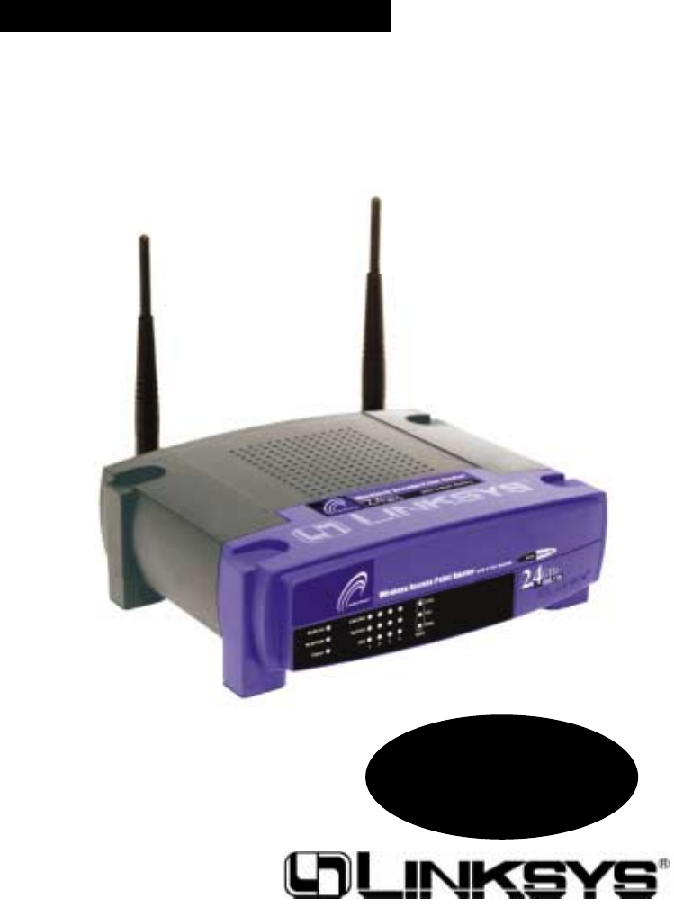
Instant Wireless™ Series
Wireless Access Point Router
with 4-Port Switch
Use this Guide to install:
BEFW11S4 Fast Start
Guide

EC DECLARATION OF CONFORMITY (EUROPE)
Linksys Group declares that the Instant Wireless™ Series products included in the Instant
Wireless™ Series conform to the specifications listed below, following the provisions of
the EMC Directive 89/336/EEC and Low Voltage Directive 73/23/EEC:
• ETS 300-826, 301 489-1 General EMC requirements for Radio equipment.
• EN 609 50 Safety
• ETS 300-328-2 Technical requirements for Radio equipment.
Note: This equipment is intended to be used in all EU and EFTA countries. Outdoor use
may be restricted to certain frequencies and/or may require a license for operation. For
more details, contact Linksys Corporate Compliance.
Note: Combinations of power levels and antennas resulting in a radiated power level of
above 100 mW are considered as not compliant with the above mentioned directive and
are not allowed for use within the European community and countries that have adopted
the European R&TTE directive 1999/5/EC and/or the CEPT recommendation Rec 70.03.
For more details on legal combinations of power levels and antennas, contact Linksys
Corporate Compliance.
• Linksys Group™ vakuuttaa täten että Instant Wireless IEEE 802.11 PC Card tyyppinen
laite on direktiivin 1999/5/EY, direktiivin 89/336/EEC ja direktiivin 73/23/EEC oleellis-
ten vaatimusten ja sitä koskevien näiden direktiivien muiden ehtojen mukainen.
• Linksys Group™ déclare que la carte PC Instant Wireless IEEE 802.11 est conforme
aux conditions essentielles et aux dispositions relatives à la directive 1999/5/EC, la
directive 89/336/EEC, et à la directive 73/23/EEC.
• Belgique B L’utilisation en extérieur est autorisé sur le canal 11 (2462 MHz), 12 (2467
MHz), et 13 (2472 MHz).
Dans le cas d’une utilisation privée, à l’extérieur d’un bâtiment, au-dessus d’un
espace public, aucun enregistrement n’est nécessaire pour une distance de moins
de 300m. Pour une distance supérieure à 300m un enregistrement auprès de l’IBPT
est requise. Pour une utilisation publique à l’extérieur de bâtiments, une licence de
l’IBPT est requise. Pour les enregistrements et licences, veuillez contacter l’IBPT.
• France F: Bande de fréquence restreinte: seuls les canaux 10, 11, 12, 13 (2457,
2462, 2467, et 2472 MHz respectivement) doivent être utilisés en France. Toute util-
isation, qu'elle soit intérieure ou extérieure, est soumise à autorisation. Vous pouvez
contacter l'Autorité de Régulation des Télécommuniations (http://www.art-telecom.fr)
pour la procédure à suivre.
• France F: Restricted frequency band: only channels 10, 11, 12, 13 (2457, 2462,
2467, and 2472 MHz respectively) may be used in France. License required for
every indoor and outdoor installations. Please contact ART for procedure to follow.
• Deutschland D: Anmeldung im Outdoor-Bereich notwending, aber nicht genehmi-
gungspflichtig. Bitte mit Händler die Vorgehensweise abstimmen.
• Germany D: License required for outdoor installations. Check with reseller for proce-
dure to follow.
• Italia I: E' necessaria la concessione ministeriale anche per l'uso interno. Verificare
con i rivenditori la procedura da seguire. L'uso per installazione in esterni non e' per-
messa.
• Italy I: License required for indoor use. Use with outdoor installations not allowed.
• the Netherlands NL License required for outdoor installations. Check with reseller for
procedure to follow.
• Nederlands NL Licentie verplicht voor gebruik met buitenantennes. Neem contact op
met verkoper voor juiste procedure.
1
Table of Contents
English 2
Français 30
Deutsch 58
Italiano 86
Portuguese 114
Español 142

COPYRIGHT & TRADEMARKS
Copyright © 2002 Linksys, All Rights Reserved. Instant Wireless is a trademark of
Linksys. Microsoft, Windows, and the Windows logo are registered trademarks of
Microsoft Corporation. All other trademarks and brand names are the property of their
respective proprietors.
FCC STATEMENT
The Instant Wireless™ Wireless Access Point Router with 4-Port Switch has been tested
and complies with the specifications for a Class B digital device, pursuant to Part 15 of
the FCC Rules. These rules are designed to provide reasonable protection against
harmful interference in a residential installation. This equipment generates, uses, and
can radiate radio frequency energy and, if not installed and used according to the
instructions, may cause harmful interference to radio communications. However, there is
no guarantee that interference will not occur in a particular installation. If this equipment
does cause harmful interference to radio or television reception, which is found by turn-
ing the equipment off and on, the user is encouraged to try to correct the interference by
one or more of the following measures:
• Reorient or relocate the receiving antenna
• Increase the separation between the equipment or devices
• Connect the equipment to an outlet other than the receiver’s
• Consult a dealer or an experienced radio/TV technician for assistance
Table of Contents
Introduction 4
Step 1: Connect the Router 6
Step 2: Configure the PCs 8
Step 3: Configure the Router 12
Help 16
Configuring Wireless Security 21
Configuring Wireless
Security in Windows XP 24
FSG-BEFW11S4 ver. 3-21008 TE
32
For product support and product registration, contact us at the addresses below:
E-mail europe-support@linksys.com
latam-soporte@linksys.com
Web http://www.linksys.com/international
Use the instructions in this Fast Start to help you connect the Router, configure your
PCs, and configure the Router in your network. These instructions should be all you
need to get you up and running with a basic network, sharing your Internet access.
The Router also comes equipped with more advanced functions,but these functions
should not be utilized without a further understanding of routers and networks.
These and other issues are explained in the User Guide on the Setup Wizard CD-ROM.
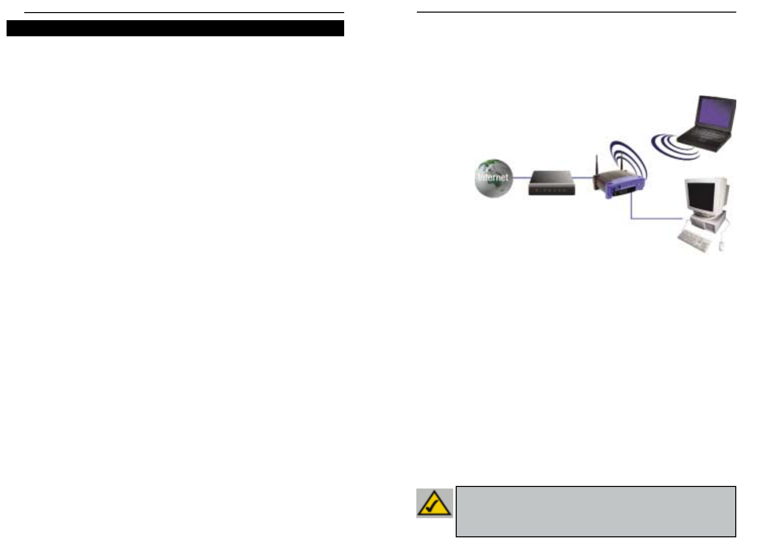
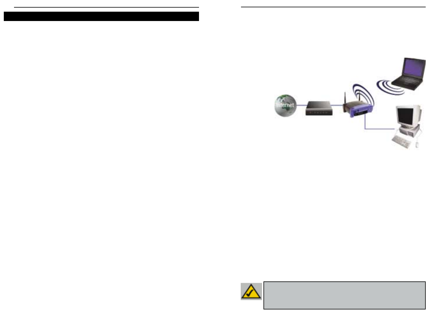
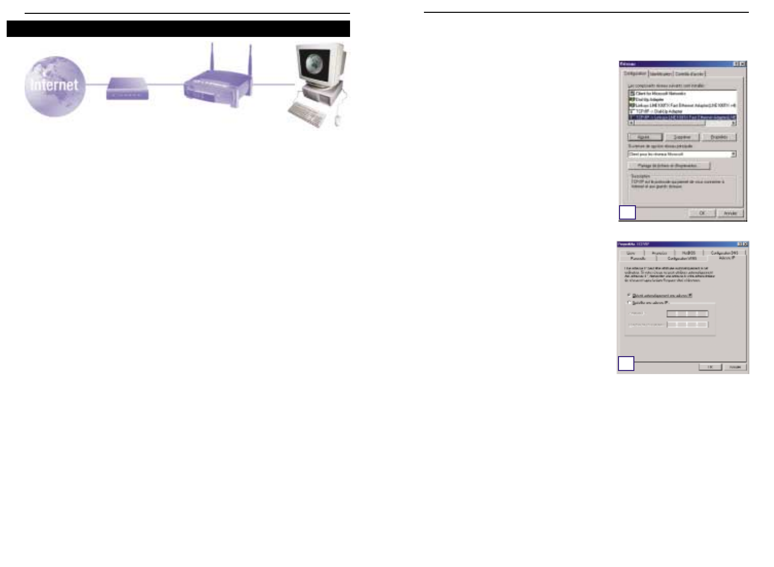
The Router’s setup is similar to that shown in the figure above for any Windows PC.
The Router lets you share your cable or DSL connection among several computers
in your home or business. This is called a Local Area Network or LAN.
This Fast Start guide gives you the “big picture” of what you need to set up a basic
home or business network. The next three sections explain how you will set up and
configure your equipment to enable shared high-speed access to the Internet.
Step 1: Connect the Router
This walks you through the process of connecting the Router to your cable or DSL
modem. Then, it shows you how your PCs are connected to the Router.
Step 2: Configure the PCs
This describes how your PCs are configured to communicate with the Router.
Step 3: Configure the Router
This step walks you through some basic Router settings, making it work with your
cable or DSL modem and your ISP’s settings.
Wireless Access Point Router with 4-Port Switch
54
Instant Wireless™ Series
Thank you for choosing the Instant Wireless™ Wireless Access Point Router. This
Router will allow you to set up a network with your PCs and even share your
Internet connection.
How does the Router do all of this? By connecting your cable or DSL modem
directly to the Router and using the Router's Ethernet ports to connect your PCs,
it's almost as if each PC is connected directly to the Internet. In this way, you can
have several PCs utilizing one Internet connection simultaneously. Plus, because
it's also an Access Point, the Router can bridge your Ethernet network with your
wireless PCs.
But what does all of this mean?
Networks are useful tools for sharing computer resources. You can access one
printer from different computers and access data located on another computer's
hard drive. Networks are even used for playing multiplayer video games. So, net-
works are not only useful in homes and offices, they can also be fun.
The PCs you connect to the Router's four LAN ports, when properly configured,
create a LAN, or Local Area Network. They are connected with an Ethernet cable
plugged into your computer's Ethernet adapter at one end and into one of the
Router's LAN ports (numbered from one to four) at the other end. The term
"Ethernet" is used to refer to your network accessories, such as cables and
adapters,because Ethernet refers to the type of network you are setting up. In your
Router's documentation, Ethernet refers to accessories that transfer computer
data from 10Mbps to 100Mbps. (10Mbps and 100Mbps refer to the speeds used
by network devices. When transferring data at 10Mbps, you are moving the equiv-
alent of over seven floppy disks every second! Network accessories that function
at 100Mbps move data ten times faster!)
PCs can also interact with the Router wirelessly. By configuring your wireless PCs
with the same wireless settings as the Router, you can bridge these wireless PCs
while integrating them into your existing Ethernet network.
Perhaps the most remarkable thing the Router does is to allow you to share your
cable or DSL connection. This is done by connecting your cable or DSL modem to
the Router's WAN port with an Ethernet cable. (WAN refers to a Wide Area
Network.) The Internet is a network that, being global, covers the widest area of
all! The PCs connected to the Router share this connection.
Introduction
NNoottee::This Fast Start Guide will direct you how to set up the Router with
Ethernet cables. While the Router can be set up through a wireless connec-
tion, details about setting up the Router wirelessly will not be addressed in
this Fast Start Guide. Those who wish to set up the Router through their wire-
less connection should refer to the Linksys website at www.linksys.com.
This is What You Will Be Setting Up

In Step 1, you will connect the Router to your cable or DSL modem and to your
home or business computers.
First,make sure that all devices you’ll be working with are powered down, includ-
ing your PCs, modem, and the Router.
A. If you haven’t already done so, connect your cable or DSL modem to its prop-
er connection—the coaxial jack for cable (Figure A1),or the phone jack for DSL
(Figure A2). (Follow the instructions from your cable or DSL modem’s installa-
tion guide.)
Instant Wireless™ Series
6
B. Using an Ethernet cable, connect the
LAN or Ethernet port of the cable or DSL
modem to the Router’s WAN port.
C. Connect an Ethernet cable to
your PC’s Ethernet adapter.
Connect the other end of the
cable to one of the Router’s
LAN ports. Repeat this
process for every PC you wish
to connect to the Router.
Note: If your PC’s Ethernet adapter is not set up, please refer to the Ethernet
adapter’s documentation for more information.
For ease of installation, start with LAN
Port 1 on the Router, then Port 2, Port 3,
and finally Port 4.
If you are connecting more than four
PCs to the Router, you will need to con-
nect a hub or switch to the Router’s
Uplink port (if you use the Uplink port,
then you cannot use Port 4). For infor-
mation on Uplinking,please refer to the
User Guide located on the Setup Wizard
CD-ROM.
D. Connect the power adapter to the Router’s Power port. Then, connect the
power adapter to an electrical outlet. Turn on the cable or DSL modem. Then
turn on the first PC you wish to use when configuring the Router.
Proceed to Step 2: Configure the PCs on the next page.
7
Wireless Access Point Router with 4-Port Switch
A1A2
Step 1: Connect the Router
B
C1
C2
In Step 2, you will configure each of your computers to communicate with the
Router.
To do this,you will need to configure your PC’s network settings to obtain an IP (or
TCP/IP) address automatically. Computers use IP addresses to communicate with
each other across a network or the Internet.
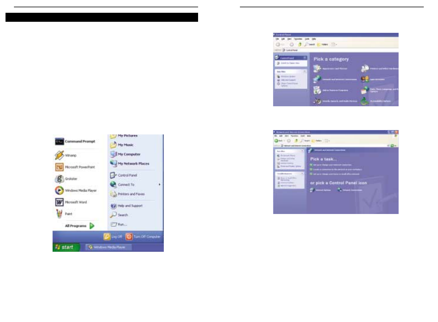
Find out which operating system your computer is running, such as Windows 95,
98, Millennium, 2000, or XP. You will need to know which operating system your
computer is running. You can find out by clicking the Start button and then select-
ing the Settings option. (If your Start menu doesn’t have a Settings option, you’re
running Windows XP. You can select the Control Panel directly from the Start
Menu.) Then, click Control Panel and double-click the System icon. Click the
Cancel button when done.
Once you know which Windows operating system you are running, follow the
directions in this step for your computer’s operating system. You may need to do
this for each computer you are connecting to the Router.
The next few pages tell you, step by step, how to configure your TCP/IP settings
based on the type of Windows operating system you are using. Once you've con-
figured your computers, continue to Step 3: Configure the Router.
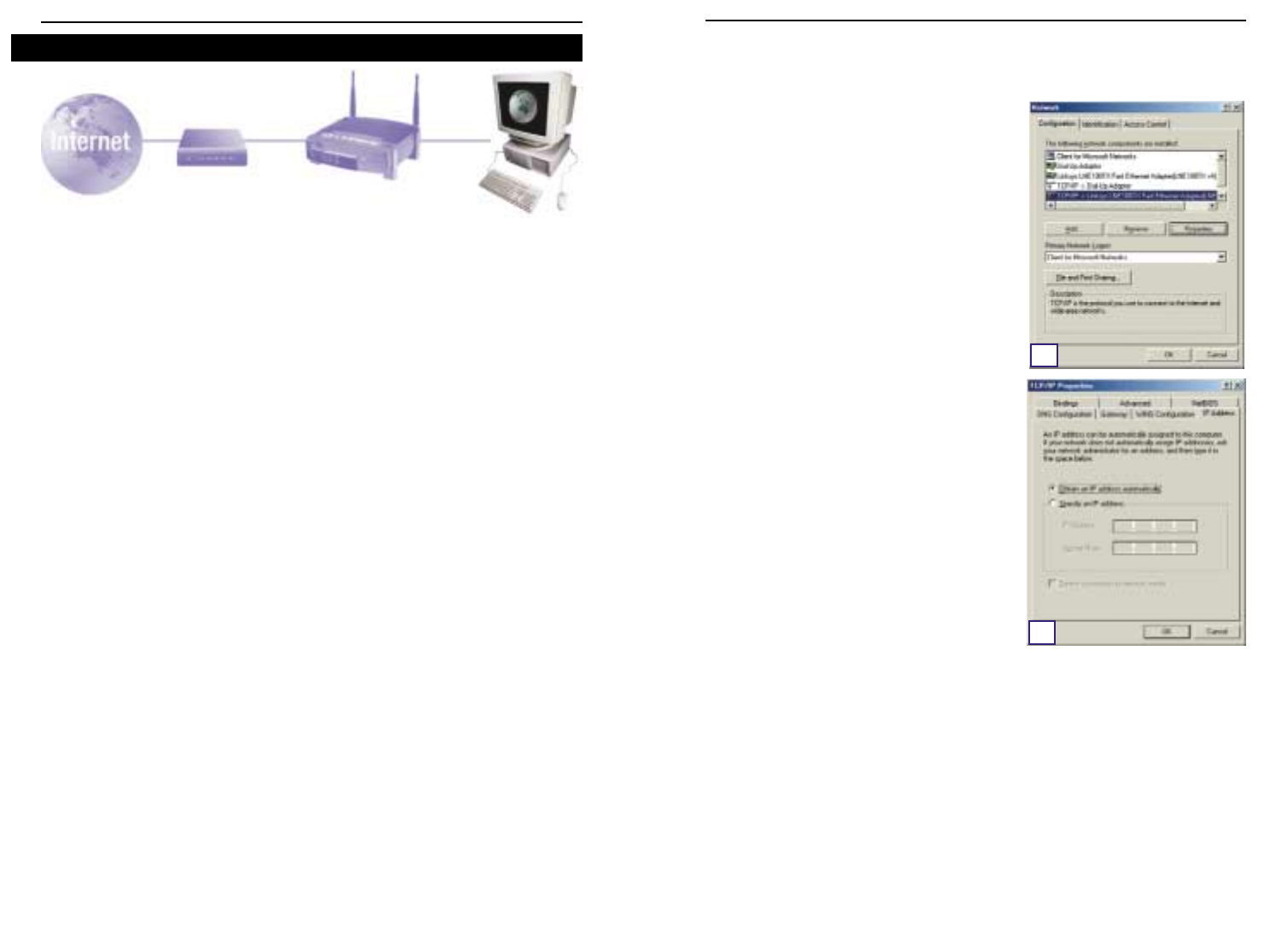
A. Click the Start button, click Settings and
open the Control Panel. From there, dou-
ble-click the Network icon to open the
Network screen.
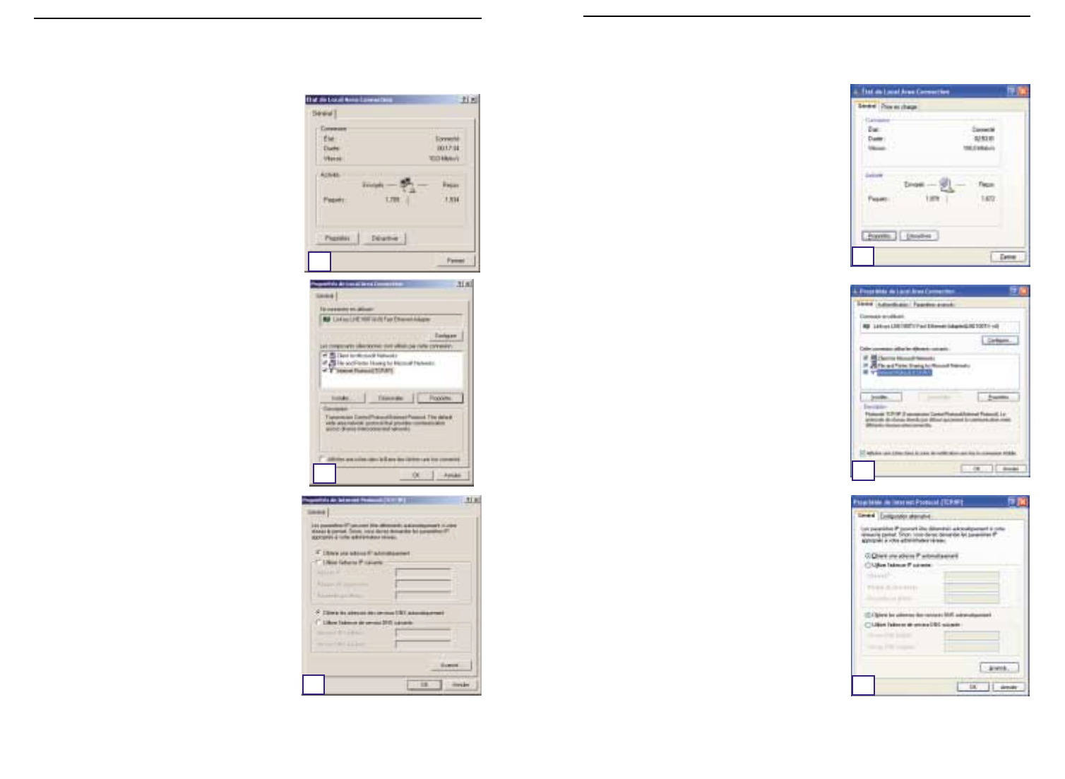
B. Select the Configuration tab and highlight
the TCP/IP line for the applicable
Ethernet adapter*. If the word TCP/IP
appears by itself, select that line**. Then,
click the Properties button.
C. Click the IP Address tab and select
Obtain an IP address automatically.
D. Click the Gateway tab and verify that the
Installed Gateway field is blank. Click the
OK button.
E. Click the OK button again. Windows may
ask you for the original Windows installa-
tion disk or additional files. Supply them
by pointing to the correct file location,e.g.,
D:\win98, D:\win9x, c:\windows\options\cabs, etc. (This assumes that “D” is
the letter of your CD-ROM drive).
F. If Windows asks you to restart your PC, click the Yes button. If Windows does
not ask you to restart, restart your computer anyway.
*Note: Do not choose a TCP/IP entry whose name mentions DUN, PPPoE, VPN, or
AOL.
**Note: If there is no TCP/IP line listed, refer to the User Guide found on the Setup
Wizard CD-ROM or your Ethernet adapter’s documentation to install TCP/IP
now.
8 9
Instant Wireless™ Series Wireless Access Point Router with 4-Port Switch
Step 2: Configure the PCs If you are running:
Windows 95, Windows 98, Windows Me
B
C
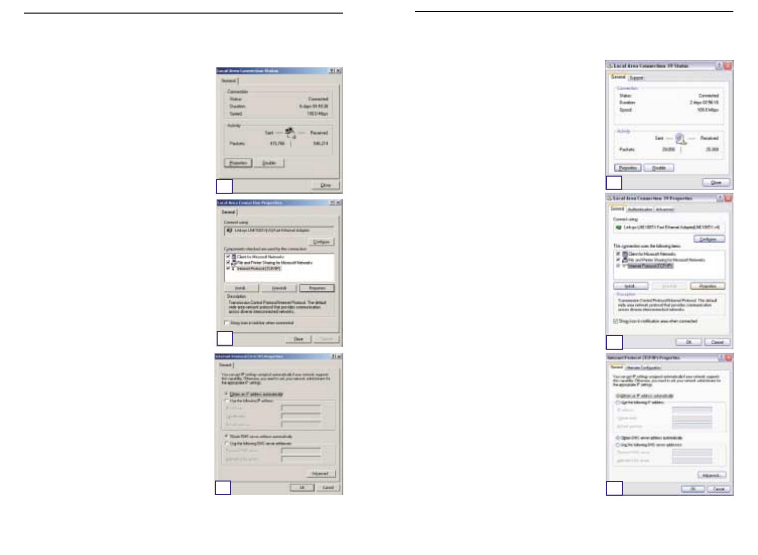
The following instructions assume you are run-
ning Windows XP’s default interface. If you are
using the Classic interface (where the icons
and menus look like previous Windows ver-
sions), please follow the instructions for
Windows 2000.
A. Click the Start button, open the Control
Panel. and click the Network and Internet
Connections icon. Then, click the Network
Connections icon to display the Network
screen.
B. Select the Local Area Connection icon for
the applicable Ethernet adapter (usually it
is the first Local Area Connection listed).
Double-click Local Area Connection.
C. When the Local Area Connection Status
screen appears, click the Properties but-
ton.
D. Select Internet Protocol (TCP/IP) and
click the Properties button.
E. Select Obtain an IP address automati-
cally and click the OK button on the subse-
quent screens to complete the PC’s config-
uration.
F. Restart your computer.
A. Click the Start button, click Settings and
open the Control Panel. From there, dou-
ble-click the Network and Dial-up
Connections icon. This will display the
Network screen.
B. Select the Local Area Connection icon for
the applicable Ethernet adapter* (usually it
is the first Local Area Connection listed).
Double-click Local Area Connection.
C. When the Local Area Connection Status
screen appears, click the Properties but-
ton.
D. Select Internet Protocol (TCP/IP) and
click the Properties button.
E. Select Obtain an IP address automatical-
ly and click the OK button on the subse-
quent screens to complete the PC’s config-
uration.
F. Restart your computer.
*Note: Do not choose a TCP/IP entry whose
name mentions DUN,PPPoE,VPN, or AOL.
10 11
Instant Wireless™ Series Wireless Access Point Router with 4-Port Switch
If you are running:
Windows 2000
E
D
C
If you are running:
Windows XP
C
D
E
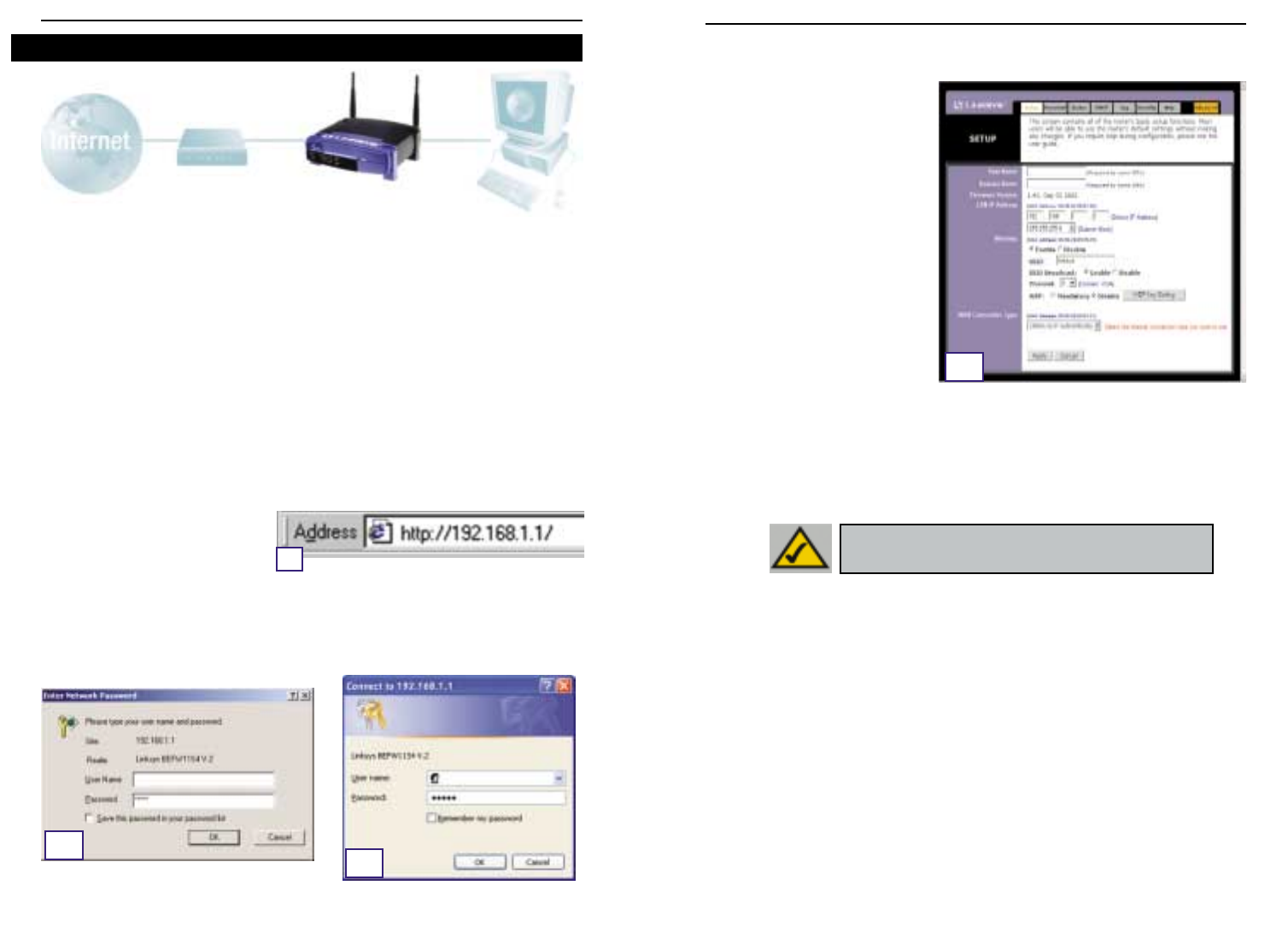
C. If required by your ISP,enter the Router’s Host Nameand Domain Namein the
appropriate fields on the Setup tab. (This is usually required by cable ISPs.)
D. To configure the Router for
your wireless network, verify
that the Setup tab’s Wireless
fields (shown in Figure D) are
completed as follows:
Enable/Disable: Selecting
the Enable radio button will
enable the Router’s wireless
feature. Wireless functions
will not be available unless
enabled.
SSID:The SSID (or ESSID) is a
unique name for your wire-
less network. It is case sen-
sitive and must not exceed 32 characters. The default SSID is "linksys " but
you should change this to a personal wireless network name. All wireless
points in your network must use the same SSID.
Channel:Select the appropriate channel for your network from the list provid-
ed. All wireless points in your network must use the same channel in order to
function properly.
E. The Router supports five connection types: DHCP (obtain an IP automatically),
PPPoE, Static IP Address, RAS, and PPTP. These types are selected from the
pull-down menu beside WAN Connection Type. The Setup screen and avail-
able features will differ depending on what kind of connection type you select,
the instructions for which are included here:
1. Obtain an IP Automatically
If your ISP says that you are connecting through a dynamic IP address (or DHCP),
perform these steps:
a. Select Obtain an IP automatically as the WAN Connection Type (as previous-
ly shown in Figure D).
b. Click the Apply button to save the settings.
In Step 3,you will configure the Router to function in your network and gain access
to the Internet through your Internet Service Provider (ISP). Your ISP may require
the use of a Host Name and Domain Name. Further, you will set the WAN
Configuration Type on the Router’s Setup tab from the information given by your
ISP.
You will need this setup information from your ISP.
If you do not have this infor-
mation,please contact your ISP before proceeding. To find out what questions you
should ask your ISP, refer to question #1 in the Help section.
The instructions from your ISP tell you how to set up your PC for Internet access.
Since you are now using the Router to share Internet access among several com-
puters, you will use this setup information for Router configuration.
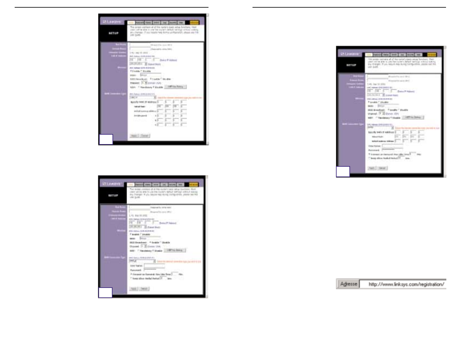
A. Open your web browser. (It’s all right if you get an error message at this point.
Continue following these instructions) Enter 192.168.1.1 into the web brows-
er’s Address field and press
the Enter key.
B. An Enter Network Password window, shown in Figure B1, will appear.
(Windows XP users will see a Connect to 192.168.1.1 window,shown in Figure
B2.) Leave the User Name field empty,and enter admin (the default password)
in lowercase letters in the Password field. Then, click the OK button.
12 13
Instant Wireless™ Series Wireless Access Point Router with 4-Port Switch
Step 3: Configure the Router
A
B1B2
D
NNoottee:: If you are interested in changing the Router’s WEP set-
tings, turn to the section for Configuring Wireless Security.

Wireless Access Point Router with 4-Port Switch
4. RAS
RAS is a service used in Singapore only. If you are using a RAS connection, check
with your ISP for the necessary setup information.
5. PPTP
PPTP is a service used in Europe
only. If you are using a PPTP con-
nection, check with your ISP for
the necessary setup information.
F. If you haven’t already done so, click the Apply button to save the settings.
G. Reset the power on your cable or DSL modem and restart your computers.
They will now obtain the Router's new settings.
Note: You only need to configure the Router from one computer. If you need
advanced setting information, please refer to the Linksys support website at
support.linksys.com
or the User Guide on the Setup Wizard CD-ROM.
Congratulations! You’ve successfully configured the Router. You can test the
setup by opening your web browser from any computer and entering
www.linksys.com/registration
.
If you are unable to reach our
website, you may want to review what you did in this section or refer to the
Help section in this Fast Start guide.
15
Instant Wireless™ Series
2. Static IP
If your ISP says that you are con-
necting through a static (or fixed)
IP address,perform these steps:
a. Select Static IP as the WAN
Connection Type.
b. In the fields beside “Specify
WAN IP Address”, enter the IP
Address.
c. Enter the Subnet Mask.
d. Enter the Default Gateway
Address.
e. Enter the DNS in the 1, 2,
and/or 3 fields. You must enter at least one DNS address.
f. Click the Apply button to save the settings.
3. PPPoE
If your DSL provider says that you
are connecting through PPPoE or
if you normally enter a user name
and password to access the
Internet, perform these steps:
a. Select PPPoE as the WAN
Connection Type.
b. Enter the User Name.
c. Enter the Password.
d. Click the Apply button to save
the settings.
e. Click the Status tab, followed by the Connect button, to start the connection.
14
E2
E3
E5

Wireless Access Point Router with 4-Port Switch
2. I’m having problems connecting to the Internet, what LEDs should be lit
on the front of the Router?
•Each Router’s LED will light up for any proper connection made on the back of
the Router—whether it is an Ethernet cable or power cord.
For example, the following are typical LEDs that light up once a computer and
a cable or DSL modem are connected:
- When the Router is turned on (the power adapter is plugged into the
Router), the
Power
LED lights up.
- When an Ethernet cable is properly connected between a PC and Port 4 of
the Router, the
Link/Act
,
Ful/Col
, and
100
LEDs in Column 4 light up.
- A cable or DSL modem connection causes the
WAN Link
LED to light up.
17
Instant Wireless™ Series
The Help section contains the most frequently asked Internet connection ques-
tions. If you have additional setup needs or you wish to get information on the
Advanced Features,please visit
kb.linksys.com
or see the User Guide, which con-
tains a Troubleshooting appendix (available on the Setup Wizard CD-ROM).
1. I’m not sure what information I need from my Internet Service Provider
(ISP) to get my network up and running. What questions should I ask?
What type of connection do I have: dynamic IP address, static IP address, or
PPPoE?
•If I am using a dynamic IP address, I should ask:
- What is my Host Name (if needed)?
- What is my Domain Name (if needed)?
•If I am using a static IP address, I should ask:
- What is my IP Address?
- What is my Gateway?
- What is my DNS?
•If I am using PPPoE (typically used by DSL ISPs), I should ask:
- What is my User Name?
- What is my Password?
After you obtain the information, follow the instructions in the Fast Start - Step 3:
Configure the Router, and use this information to enter on the Setup tab. In the
WAN Connection Type section, refer to the chart on the next page:
16
Help ?Dynamic IP
Address (DHCP) 1. Select Obtain an IP automatically as the WAN
Connection Type.
2. Click the Apply button to save the setting.
Perform these steps:
PPPoE 1. Select PPPoE as the WAN Connection Type.
2. Enter the User Name.
3. Enter the Password.
4. Click the Apply button to save the settings.
Static IP Address 1. Select Static IP as the WAN Connection Type.
2. Enter the IP Address.
3. Enter the Subnet Mask.
4. Enter the Gateway Address.
5. Enter the DNS in the 1, 2, and/or 3 fields. You need to
enter at least one DNS address.
6. Click the Apply button to save the settings.
RAS or PPTP If you are using RAS (Singapore SingTel) or PPTP (service
in Europe), check with your ISP for the necessary setup
information.
If you have this type
of connection:

Wireless Access Point Router with 4-Port Switch
•The IP Address field should show an IP address of 192.168.1.100 or
192.168.1.xxx, with “xxx” being any number greater than 100.
If your IP address is not in that range, hold the reset button on the front
of the Router for more than 30 seconds. This will cause your Router to be
set to factory default, so you will need to re-configure the Router's Setup
page. After re-configuring the Setup page,restart the computer.
C. Now you will configure some settings in Windows.
- Go to your desktop and double-click My Computer, and then double-click
Control Panel (Windows XP users using the default interface, click Start, and
then select Control Panel).
- When the Control Panel window pops up, double-click the Internet Options
icon (Windows XP users using the default interface, click Network and
Internet Connections, and then click Internet Options).
- When the Internet Options window appears, click the Connections tab.
- Check Never Dial Up a Connection. (If this choice is grayed out,that is fine.)
- Click the LAN Settings … button in the lower right-hand corner.
- When the Local Area Network (LAN) Settings window appears,uncheck all boxes.
- Click the OK button and the Apply button (the Apply button will be grayed out
if you did not have to make any changes). Then click the OK button again.
- Exit the Control Panel, and restart your computer.
4. When I click on the icon to access the Internet, and enter the user name
and password that my ISP gave me, I cannot connect to the Internet.
What is wrong?
This means that you’re using the software given to you by your ISP. Please use
Internet Explorer or Netscape Navigator, which is located on your desktop (located
on the Start Menu in Windows XP).
5. When I use Internet Explorer, a box pops up prompting me to dial up a
connection. How can I disable that?
A. Go to your desktop and double-click My Computer, and then double-click
Control Panel (Windows XP users using the default interface, click Start, and
then select Control Panel).
B. When the Control Panel window pops up, double-click the Internet Options
icon (Windows XP users using the default interface, click Network and
Internet Connections, and then click Internet Options).
C. When the Internet Options window appears, click the Connections tab.
19
Instant Wireless™ Series
•My
WAN Link
LED isn’t lit. What should I check?
- Check that the cable you are using between your cable or DSL modem
and the Router is the same cable that came with your modem. Depending
on the type of connection your modem uses, you may need either a
“straight-through” or “crossover” Ethernet cable (the “straight-through”
type is more common).
•Some of the lights on the front of the Router don’t light up when I plug in a PC.
- Only the
Link/Act
LED is required for a connection to work correctly.
3. I cannot get onto the Internet, nor can I access the Router’s Setup page.
What should I check?
A. First check that the cable or DSL modem and computers are properly con-
nected to the Router. See Question #2 for how to verify that the connections
are good.
B. Then, check that you have properly configured your PCs to communicate with
the Router. Below you will find instructions for the various versions of
Windows.
-Windows 95, 98, or ME
•Click the Start menu,and then click Run. After the Run window appears,
enter winipcfg in the Open field, and then click the OK button.
•When the IP Configuration window appears, click the gray box with a
black arrow pointing down.
•A list of adapters will appear. Select the adapter that you use to connect
to the Internet. These items should not contain “PPP”, “VPN”, “AOL”, or
“Dial-Up adapter” as part of the entry.
•The IP Address field should show an IP address of 192.168.1.100 or
192.168.1.xxx, with “xxx” being any number greater than 100.
If your IP address is not in that range, hold the reset button on the front
of the Router for more than 30 seconds. This will cause your Router to be
set to factory default, so you will need to re-configure the Router's Setup
page. After re-configuring the Setup page,restart the computer.
-Windows NT, 2000, and XP
•Click the Start menu,and then click Run. After the Run window appears,
enter cmd in the Open field, and then click the OK button.
•This will open a command prompt. Enter ipconfig /all and then press the
Enter key.
18
Wireless Access Point Router with 4-Port Switch
21
Instant Wireless™ Series
D. Check Never Dial Up a Connection.
E. Click the Apply button.
F. Click the OK button.
6. I get no signal strength or link quality or signal strength, what can I do?
A. Verify that the Router’s WLAN LED is illuminated.
B. Verify that all of your wireless PCs are using “Infrastructure” mode.
7. How can I improve the Router’s range?
A. Verify that the Router is as high off of the ground as possible.
B. Verify that there are no large sources of electrical interference nearby. (For
example: speakers breaker boxes,florescent lights, microwaves, etc.)
C. Change the wireless channel being used. To do this:
- Open your web browser and type http://192.168.1.1 into the "Address" field.
- In the "Enter Network Password" box, leave the "User Name" field blank and
type admin as the password. Then,click OK.
- From the Setup tab, change the channel to 1.
- Click the Apply button to save the settings.
- Continue doing this until you find the channel that provides the best range.
20
An acronym for Wired Equivalent Privacy, WEP is an encryption method used
to protect your wireless data communications. WEP uses a combination of 64-
bit or 128-bit keys to provide access control to your network and encryption
security for every data transmission. To decode a data transmission, each point
in a network must use an identical 64-bit or 128-bit key. Higher encryption lev-
els mean higher levels of security, but due to the complexity of the encryption,
they may mean decreased network performance.
You may also have heard the term “40-bit” used in conjunction with WEP
encryption. This is simply another term for 64-bit WEP encryption. This level
of WEP encryption has been called 40-bit because it uses a 40-bit secret key
along with a 24-bit Initialization Vector (40 + 24 = 64). Wireless vendors may
use either name. Linksys uses the term “64-bit” when referring to this level of
encryption.
Make sure your wireless network is functioning before attempting to configure
WEP encryption.
A 128-bit WEP encrypted wireless network will NOT communicate with a 64-
bit WEP encrypted wireless network. Therefore, make sure that all of your
wireless devices are using the same encryption level. All wireless devices com-
plying with the 802.11b standard will support 64-bit WEP.
In addition to enabling WEP, Linksys also recommends the following security
implementations:
•Changing the SSID from the default “linksys”
•Changing the WEP key regularly
Note: WEP encryption is an additional data securi-
ty measure and not essential for router operation.
Note: In order for WEP Encryption to be enabled, wireless functions must first
be enabled. Select Enable on the Router’s Wireless tab before proceeding.
Configuring Wireless Security
Wireless Access Point Router with 4-Port Switch
23
Instant Wireless™ Series
22
• WEP (64Bit or 128B) Select the level of encryption from the drop-down
box. 128-bit WEP encryption is unique to Linksys and may conflict with
other vendors’ WEP encryption.
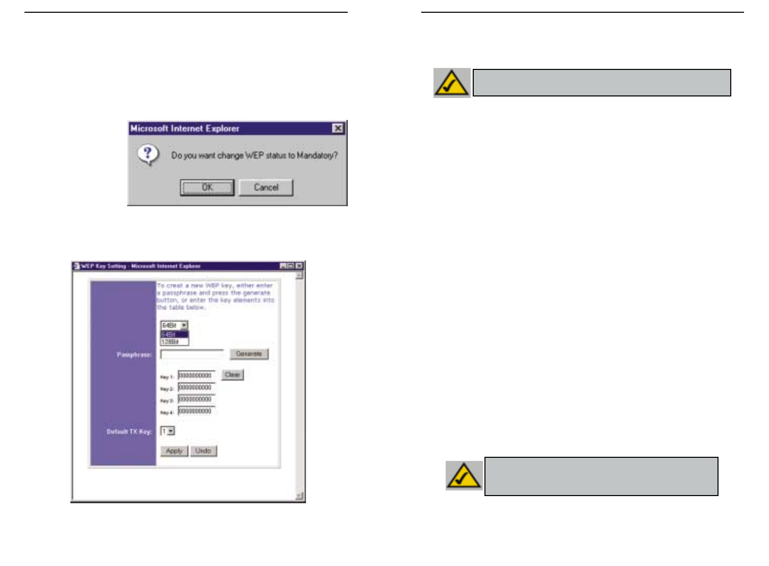
The WEP Encryption key is generated in one of two ways:
1. You may create an encryption key by using a Passphrase.
a. Enter a Passphrase, a user-defined password, into the Passphrase field.
The Passphrase can be a maximum of 31 letters, symbols, and numbers.
No spaces can be used.
b. Click the Generate button to create a key. The key will be 10 digits if
you chose 64-bit encryption, or 26 digits if you chose 128-bit encryption.
This key will be used to encrypt and decrypt the data being sent between
the Router and your network’s wireless PCs.
The Key field may not display all digits. Using the mouse, click any-
where within the Key field. Move the cursor to the right to view the rest
of the Key. Make sure your write down the entire Key EXACTLY the
way it is displayed.
2. You may enter the encryption key manually.
Make a note of the Passphrase or Manual Key. You will need it for the other
wireless devices on the network, as the same WEP encryption key must be
entered in all wireless devices on the network.
Once you have chosen your key encryption method and entered either the
Passphrase or manual key, click the Apply button, and the encryption portion
of the setup is complete.
Note: In order to utilize WEP encryption, all points in your wireless
network must have WEP enabled and be set to the same Key Setting.
Note: In Windows XP, a 128-bit Key generated by the Router
will be called a "104 bits (26 digits)" key, and a 64-bit Key gen-
erated by the Router will be called a “40 bits (10 digits)” key.
The following steps will show you how to utilize WEP encryption
1. From the Web-based Utility’s Setup tab, select Mandatory under the WEP
section.
2. Press the WEP Key Setting button to set the WEP Encryption type and
level.
3. The screen dis-
played in Figure
C-1 may appear,
verifying that you
are enabling WEP
Encryption. Press
the OK button to
continue.
4. This will display the screen shown in Figure C-2. From this screen, you will
choose your WEP Encryption settings.
Figure C-2
Figure C-1
Wireless Access Point Router with 4-Port Switch
25
Instant Wireless™ Series
24
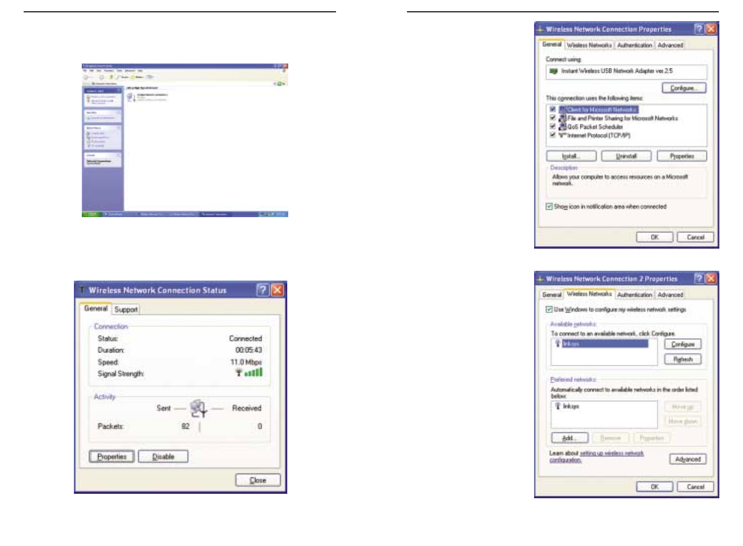
2. In the “Control Panel” window, click the Network and Internet
Connections icon, shown in Figure C-4.
3. Click the Network Connections icon, shown in Figure C-5.
4. The “Network Connections” window will appear, as shown in Figure C-6.
Under LAN or High-Speed Internet you will see all Network cards that are
installed and operating in your computer. Double-click the Wireless
Network Connection icon associated with your wireless adapter.
If the “Wireless Network Connection Status” window appears, continue to
the next step
Figure C-4
Figure C-5
As Windows XP does not allow for the use of the Linksys Passphrase feature
with the wireless PC adapters, you will need to manually enter the key gener-
ated in the previous section.
The following steps will help you enable WEP and enter the encryption key
manually for your wireless PC cards, in order to enable your Windows XP sys-
tem to communicate with the Router wirelessly.
These steps assume that your CD-ROM drive is letter D and that you are run-
ning Windows XP in the default mode.
Be sure you have the WEP Key generated by the Router.
1. As shown in Figure C-3, click the Start button and go to the Control Panel.
Figure C-3
Configuring Wireless Security in Windows XP
Wireless Access Point Router with 4-Port Switch
27
Instant Wireless™ Series
26
6. When the “Wireless
Network Connection
Properties” window
appears, as in Figure C-
8, click the Wireless
Networks Tab.
7. If the appropriate wire-
less network, specified
by the Router’s SSID, is
displayed in the
“Preferred networks”
section, as shown in
Figure C-9, double-
click it and continue to
the next step.
Otherwise, click on the
appropriate wireless
network, specified by
the Router’s SSID, in
the “Available net-
works” section. Then,
click the Configure
button
Figure C-8
Figure C-9
If a “Connect to Wireless Network” window appears, in the Available
Networks section, click the desired wireless network, specified by the
Router’s SSID. Then, double-click the Wireless Network Connection icon.
5. When the “Wireless Network Connection Status” window appears, as in
Figure C-7, click the Properties button.
Figure C-6
Figure C-7
29
Instant Wireless™ Series
28
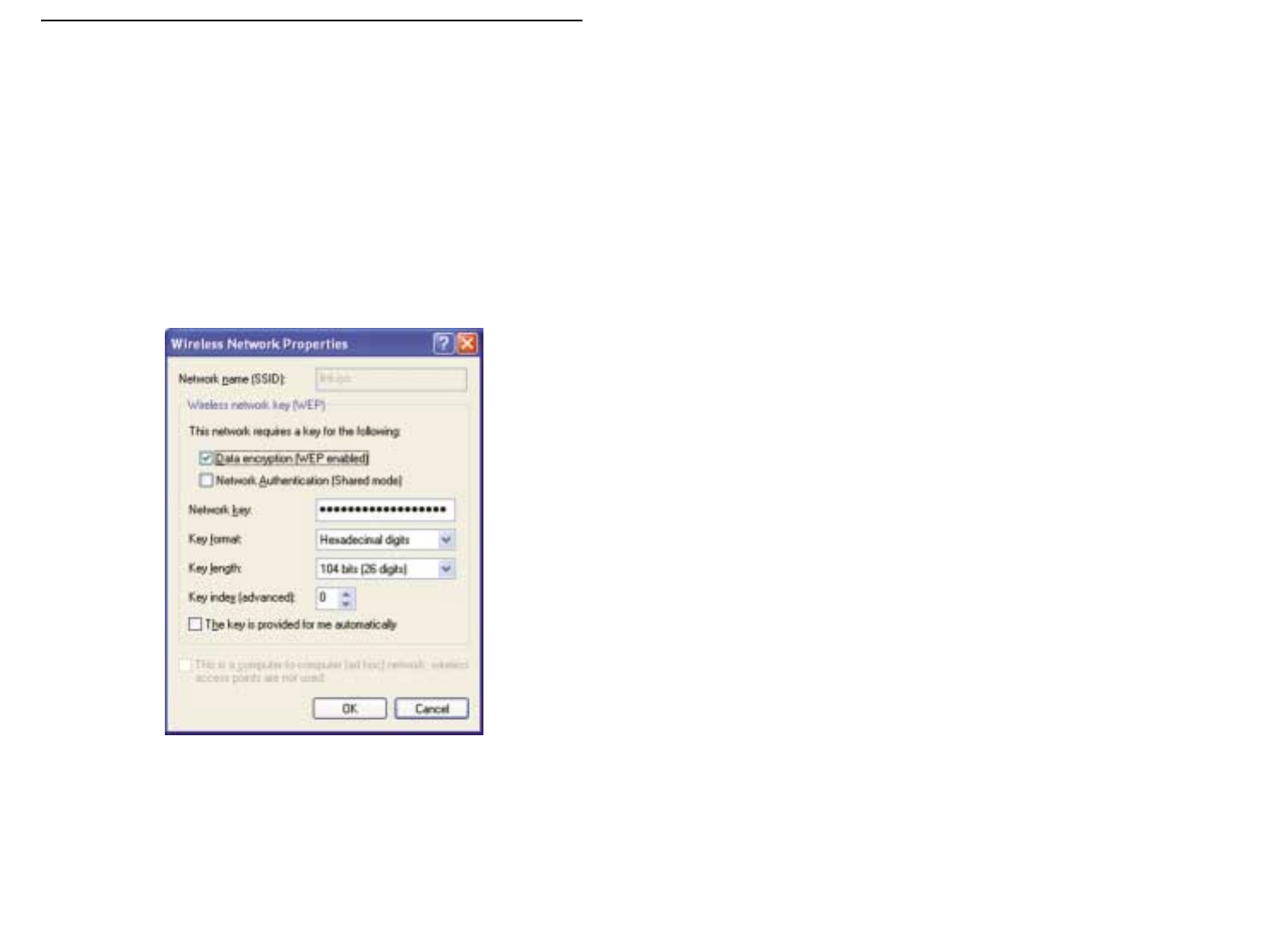
8. The “Wireless Network Properties” window (shown in Figure C-10) will
appear.
Click the check box for the Data encryption (WEP enabled) option.
Remove the check from the Network Authentication (Shared mode) and
The key is provided for me automatically fields.
In the "Network key" field, enter the exact Key (all 10 or 26 digits, depend-
ing on the level of encryption) generated by the Router.
Verify that the “Key format” field displays “Hexadecimal digits” and that
the “Key length” field displays either “40 bits (10 digits)” or “104 bits (26
digits)”. If this is not displayed, you have entered the key incorrectly.
Click the OK button to save the settings. Click on OK buttons until you
get back to the “Wireless Network Connection Status” window. Close any
open windows to get back to the Windows XP desktop.
Close any applications and reboot your PC. After reboot, WEP configuration
is complete and you should be able to connect wirelessly to the Router.
Figure C-10

3130
COPYRIGHT ET MARQUES
Copyright © 2002 Linksys, Tous droits réservés. Instant Wireless est une marque de
commerce de Linksys. Microsoft, Windows et le logo Windows sont des marques
déposées de Microsoft Corporation. Toutes les autres marques de commerce et
tous les autres noms commerciaux appartiennent à leurs propriétaires respectifs.
AVIS DE CONFORMITÉ FCC
Les tests de conformité effectués sur le routeur de point d’accès sans fil avec commu-
tateur 4 ports Instant Wireless™ ont montré qu’il respecte les limites fixées pour un
appareil numérique de classe B en vertu de l’article 15 des règlements de la FCC. Ces
limites sont conçues pour apporter une protection adéquate contre le brouillage
radioélectrique préjudiciable des installations résidentielles. Cet équipement produit,
utilise et peut émettre de l’énergie radioélectrique et il peut, lorsqu’il n’est pas installé et
utilisé conformément aux instructions données, causer un brouillage préjudiciable des
radiocommunications. Cependant, rien ne garantit qu’une installation particulière ne pro-
duira pas de brouillage. Si l’appareil venait à causer un brouillage préjudiciable de la
réception d’émissions radio ou télévisuelles, ce qui peut être déterminé en l’éteignant et
en le rallumant, nous vous conseillons d’essayer d’y remédier en prenant une ou
plusieurs des mesures suivantes :
• réorienter ou déplacer l’antenne de réception ;
• éloigner l’appareil du récepteur ;
• brancher l’appareil et le récepteur sur des prises de courant différentes ;
• consulter le revendeur ou un technicien radiotélévision expérimenté.
Table des matières
Introduction 32
Étape 1 : connexion du routeur 34
Étape 2 : configuration des PC 36
Étape 3 : configuration du routeur 40
Aide 44
Configuration de la sécurité sans fil 49
Configuration de la sécurité sans fil dans
Windows XP 52
Pour le support produit, contactez-nous aux adresses indiquées ci-dessous :
E-mail europe-support@linksys.com
latam-soporte@linksys.com
Web http://www.linksys.com/international
3332
Utilisez les instructions de ce Guide de démarrage rapide pour connecter le routeur, configurer
vos PC et configurer le routeur sur votre réseau. Ces instructions contiennent toutes les infor-
mations nécessaires à la mise en service d’un réseau de base avec partage de votre accès à
Internet. Le routeur est également équipé de fonctions plus avancées, mais elles ne doivent
pas être utilisées sans une connaissance approfondie des routeurs et des réseaux. Celles-ci,
ainsi que d’autres sujets, sont abordés dans le Guide de l’utilisateur figurant sur le CD-ROM
Setup Wizard (Assistant Installation).
La configuration du routeur est similaire à celle illustrée à la figure ci-dessus pour tout PC
Windows. Le routeur vous permet de partager votre connexion DSL ou par câble entre
plusieurs ordinateurs à domicile ou au bureau. Cela s’appelle un réseau local ou LAN.
Ce Guide de démarrage rapide vous donne un « aperçu général » de ce dont vous avez besoin
pour configurer un réseau de base chez vous ou au bureau. Les trois prochaines sections
expliquent comment installer et configurer votre équipement pour permettre un accès partagé
et grande vitesse à Internet.
Étape 1 : connexion du routeur
Cette étape vous guide à travers la procédure de connexion du routeur à votre modem câble
ou DSL. Elle explique ensuite comment connecter vos PC au routeur.
Étape 2 : configuration des PC
Cette étape indique comment configurer vos PC pour communiquer avec le routeur.
Étape 3 : configuration du routeur
Cette étape décrit certains paramètres de base du routeur qui lui permettent de fonctionner
avec votre modem câble ou DSL de même qu’avec les paramètres de votre ISP.
Routeur de point d’accès sans fil avec commutateur 4 ports
Instant Wireless™ Series
Merci d’avoir choisi le routeur de point d’accès sans fil Instant Wireless™. Ce routeur per-
met de relier des PC en réseau et même de partager une connexion Internet.
Comment le routeur procède-t-il ? En connectant votre modem câble ou DSL directement au
routeur et en utilisant les ports Ethernet du routeur pour relier vos PC,c’est un peu comme
si chaque PC était directement connecté à Internet. Plusieurs PC peuvent ainsi utiliser
simultanément une même connexion Internet. Le routeur constituant également un point
d’accès, il peut établir un pont entre votre réseau Ethernet et vos PC sans fil.
Possibilités offertes
Les réseaux constituent de puissants outils pour partager des ressources informatiques.
Vous pouvez utiliser une imprimante depuis différents ordinateurs et accéder aux données
résidant sur le disque dur d’un autre ordinateur. Les réseaux permettent également d’uti-
liser à plusieurs des jeux vidéo. Les réseaux sont donc non seulement très utiles,mais peuvent
également s’avérer ludiques.
Les PC que vous connectez aux quatre ports de réseau local du routeur, s’ils sont correcte-
ment configurés, créent un réseau local. Ils sont connectés au moyen d’un câble Ethernet
branché à une extrémité sur l’adaptateur Ethernet de l’ordinateur et sur les ports de réseau
local du routeur (numérotés de 1 à 4) à l’autre extrémité. Le terme « Ethernet » fait
référence aux accessoires de réseau, tels que câbles et adaptateurs, et désigne le type de
réseau mis en place. Dans la documentation du routeur, Ethernet fait référence aux acces-
soires qui transfèrent les données informatiques à un débit compris entre 10 Mbits/s et
100 Mbits/s. 10 Mbits/s et 100 Mbits/s désignent les vitesses utilisées par les périphériques
réseau. Lors d’un transfert de données à 10 Mbits/s,vous transférez l’équivalent de plus de
sept disquettes par seconde ! Les accessoires réseau qui fonctionnent à 100 Mbits/s offrent
des débits dix fois plus rapides !
Les PC peuvent également être raccordés au routeur par une connexion sans fil. En confi-
gurant les PC sans fil avec les mêmes paramètres sans fil que le routeur, vous pouvez rac-
corder ces PC tout en les intégrant à votre réseau Ethernet existant.
Mais le routeur permet surtout de partager votre connexion câble ou DSL. Pour cela, il suf-
fit de connecter votre modem câble ou DSL au port WAN du routeur avec un câble Ethernet.
Le terme WAN (Wide Area Network) désigne un réseau étendu. Internet est un réseau glo-
bal couvrant la zone la plus vaste qui soit ! Les PC connectés au routeur partagent cette
connexion.
Introduction
RReemmaarrqquuee :: ce Guide de démarrage rapide décrit l’installation du routeur avec des
câbles Ethernet. Bien que le routeur puisse être installé au moyen d’une connexion sans
fil, cette configuration n’est pas décrite dans ce Guide de démarrage rapide. Si vous
souhaitez installer le routeur en employant une connexion sans fil, reportez-vous aux
informations présentées sur le site Web Linksys à l’adresse www.linksys.com.
Vue d’ensemble de l’installation

3534
À l’étape1, vous allez connecter le routeur à votre modem câble ou DSL, ainsi qu’aux ordi-
nateurs de votre domicile ou bureau.
Vérifiez d’abord que tous les appareils que vous utiliserez sont hors tension,notamment les
PC,le modem et le routeur.
A. Si ce n’est déjà fait,branchez votre modem câble ou DSL sur la prise adéquate :la prise
coaxiale pour câble (figure A1) ou la prise téléphonique pour DSL (figure A2). (Suivez les
instructions du Guide d’installation de votre modem câble ou DSL.)
Instant Wireless™ Series
B. À l’aide d’un câble Ethernet, raccordez le
port Ethernet du modem câble ou DSL au
port WAN du routeur.
C. Branchez un câble Ethernet sur
l’adaptateur Ethernet du PC.
Branchez l’autre extrémité du
câble sur l’un des ports de réseau
local du routeur. Recommencez
cette opération pour chaque PC à
connecter au routeur.
Remarque : si l’adaptateur Ethernet du PC n’est pas installé, reportez-vous à sa docu-
mentation pour plus d’informations.
Pour simplifier l’installation, commencez par
le port de réseau local 1 sur le routeur,puis le
port 2, le port 3 et enfin le port 4.
Si vous connectez plus de quatre PC au rou-
teur, vous devrez connecter un hub ou un
commutateur au port de liaison montante
(Uplink) du routeur (si vous utilisez le port de
liaison montante, vous ne pouvez pas utili-
ser le port 4). Pour plus d’informations sur
les liaisons montantes, reportez-vous au
Guide de l’utilisateur figurant sur le CD-ROM
Setup Wizard (Assistant Installation).
D. Branchez l’adaptateur de courant sur le port d’alimentation du routeur, puis sur une
prise électrique. Mettez le modem câble ou DSL sous tension. Mettez ensuite sous ten-
sion le premier PC à utiliser lors de la configuration du routeur.
Passez à l’étape 2 : configuration des PC (page suivante).
Routeur de point d’accès sans fil avec commutateur 4 ports
A1A2
Étape 1 : connexion du routeur
B
C1
C2
3736
À l’étape 2,vous allez configurer chacun de vos ordinateurs pour communiquer avec le rou-
teur.
Pour cela, vous devrez configurer les paramètres réseau du PC afin d’obtenir automatique-
ment une adresse IP (ou TCP/IP). Les ordinateurs emploient des adresses IP pour commu-
niquer entre eux sur un réseau ou sur Internet.
Identifiez le système d’exploitation utilisé sur votre ordinateur, par exemple Windows 95,98,
Millennium, 2000 ou XP. Vous devez savoir sous quel système d’exploitation votre ordina-
teur fonctionne. Pour cela, cliquez sur le bouton Démarrer, puis sélectionnez l’option
Paramètres. (Si le menu Démarrer ne comporte pas d’option Paramètres, vous utilisez
Windows XP. Vous pouvez accéder directement au Panneau de configuration depuis le menu
Démarrer.) Cliquez ensuite sur Panneau de configuration,puis double-cliquez sur l’icône
Système. Cliquez sur le bouton Annuler une fois que vous avez terminé.
Une fois que vous connaissez le système d’exploitation Windows utilisé, suivez les direc-
tives de cette étape correspondant au système d’exploitation de l’ordinateur. Vous devrez
éventuellement suivre cette procédure pour chaque ordinateur à connecter au routeur.
Les pages suivantes présentent la procédure pas à pas de configuration des paramètres
TCP/IP en fonction du type de système d’exploitation Windows employé. Une fois les ordi-
nateurs configurés, passez à l’étape 3 : configuration du routeur.
A. Dans le menu Démarrer, choisissez
Paramètres et ouvrez le Panneau de config-
uration. Dans le Panneau de configuration,
double-cliquez sur l’icône Réseau pour ouvrir
l’écran Réseau.
B. Sélectionnez l’onglet Configuration et mettez
en surbrillance la ligne TCP/IP de l’adaptateur
Ethernet concerné*. Si le mot TCP/IP apparaît
seul, sélectionnez cette ligne**. Cliquez ensuite
sur le bouton Propriétés.
C. Cliquez sur l’onglet Adresse IP et sélectionnez
Obtenir une adresse IP automatiquement.
D. Cliquez sur l’onglet Passerelle et vérifiez que
le champ Passerelles installées est vide.
Cliquez ensuite sur le bouton OK.
E. Cliquez de nouveau sur le bouton OK. Windows
peut vous demander la disquette d’installation
Windows d’origine ou des fichiers supplémen-
taires. Indiquez leur emplacement, par exemple
D:\win98, D:\win9x, c:\windows\options\cabs,
etc. Cela suppose que « D » soit la lettre du
lecteur de CD-ROM.
F. Si Windows vous demande de redémarrer le PC, cliquez sur le bouton Oui. Même si
Windows ne vous le demande pas, redémarrez quand même l’ordinateur.
*Remarque :ne choisissez pas une entrée TCP/IP dont le nom contient le terme DUN,PPPoE,
VPN ou AOL.
**Remarque : si aucune ligne TCP/IP n’est répertoriée, reportez-vous au Guide de l’utilisa-
teur se trouvant sur le CD-ROM Setup Wizard (Assistant Installation) ou à la documen-
tation de votre adaptateur Ethernet pour installer TCP/IP maintenant.
Instant Wireless™ Series Routeur de point d’accès sans fil avec commutateur 4 ports
Étape 2 : configuration des PC Si vous utilisez :
Windows 95, Windows 98, Windows Me
B
C
3938
Les instructions suivantes partent du principe que
vous utilisez l’interface par défaut de Windows XP. Si
vous utilisez l’interface classique (dans laquelle les
icônes et les menus ressemblent à ceux des ver-
sions précédentes de Windows), veuillez suivre les
instructions fournies pour Windows 2000.
A. Dans le menu Démarrer,ouvrez le Panneau de
configuration et cliquez sur l’icône
Connexions réseau et Internet. Cliquez
ensuite sur l’icône Connexions réseau pour
afficher l’écran Connexions réseau.
B. Sélectionnez l’icône Connexion au réseau
local pour l’adaptateur Ethernet concerné (il
s’agit généralement de la première connexion
au réseau local répertoriée). Double-cliquez sur
Connexion au réseau local.
C. Lorsque l’écran État de la connexion au réseau
local apparaît,cliquez sur le bouton Propriétés.
D. Sélectionnez Protocole Internet (TCP/IP) et
cliquez sur le bouton Propriétés.
E. Sélectionnez Obtenir une adresse IP automa-
tiquement et cliquez sur le bouton OK dans les
écrans suivants pour terminer la configuration
du PC.
F. Redémarrez l’ordinateur.
A. Dans le menu Démarrer, choisissez
Paramètres et ouvrez le Panneau de configu-
ration. Double-cliquez sur l’icône Connexions
réseau et accès à distance. L’écran Réseau
s’affiche.
B. Sélectionnez l’icône Connexion au réseau
local pour l’adaptateur Ethernet concerné* (il
s’agit généralement de la première connexion au
réseau local répertoriée). Double-cliquez sur
Connexion au réseau local.
C. Lorsque l’écran État de la connexion au réseau
local apparaît, cliquez sur le bouton Propriétés.
D. Sélectionnez Protocole Internet (TCP/IP) et
cliquez sur le bouton Propriétés.
E. Sélectionnez Obtenir une adresse IP automa-
tiquement et cliquez sur le bouton OK dans les
écrans suivants pour terminer la configuration
du PC.
F. Redémarrez l’ordinateur.
*Remarque : ne choisissez pas une entrée TCP/IP
dont le nom contient le terme DUN, PPPoE, VPN ou
AOL.
Instant Wireless™ Series Routeur de point d’accès sans fil avec commutateur 4 ports
Si vous utilisez :
Windows 2000
E
D
C
Si vous utilisez :
Windows XP
C
D
E
4140
C. Si votre fournisseur de services Internet le demande, entrez le nom d’hôte et le nom
de domaine du routeur dans les champs appropriés de l’onglet Setup (Configuration).
Ces informations sont habituellement demandées par les fournisseurs de services
Internet proposant un accès par câble.
D. Pour configurer le routeur pour
votre réseau sans fil,vérifiez que
les champs Wireless (Sans fil) de
l’onglet Setup (Configuration)
(figure D) sont renseignés de la
façon suivante :
Enable/Disable (Activer/Désactiver)
:
La sélection de la case d’option
Enable (Activer) active la fonc-
tion sans fil du routeur. Les fonc-
tions sans fil ne sont disponibles
que si elles sont activées.
SSID : L’identificateur SSID (ou ESSID) est un nom unique attribué à votre réseau
sans
fil. Il respecte la casse et ne doit pas comporter plus de 32 caractères. L’identificateur
SSID par défaut est « linksys », mais vous pouvez le remplacer par un nom de réseau sans
fil personnel. Tous les points sans fil de votre réseau doivent utiliser le même SSID.
Channel (Canal) : Sélectionnez le canal approprié pour votre réseau à partir de la liste
proposée. Tous les points sans fil de votre réseau doivent utiliser le même canal pour
fonctionner correctement.
E. Le routeur prend en charge cinq types de connexion : DHCP (obtention automatique
d’une adresse IP), PPPoE, Adresse IP permanente, RAS et PPTP. Ces types sont sélec-
tionnés dans le menu déroulant en regard de WAN Connection Type (Type de con-
nexion WAN). L’écran Setup (Configuration) et les fonctions disponibles varient selon le
type de connexion choisie. Les instructions correspondantes sont présentées ici :
1. Obtain an IP Automatically (Obtenir une adresse IP automatiquement)
Si votre fournisseur de services Internet indique que vous vous connectez par l’intermé-
diaire d’une adresse IP dynamique (ou DHCP), procédez comme suit :
a. Sélectionnez Obtain an IP automatically (Obtenir une adresse IP automatiquement)
pour WAN Connection Type (Type de connexion WAN) (comme à la figure D plus haut).
b. Cliquez sur le bouton Apply (Appliquer) pour enregistrer les paramètres.
À l’étape 3,vous configurez le routeur pour l’utiliser dans votre réseau et accéder à Internet
par l’intermédiaire de votre fournisseur de services Internet (ISP). Votre ISP peut imposer
l’emploi d’un nom d’hôte et d’un nom de domaine. Vous indiquerez aussi le type de confi-
guration WAN dans l’onglet Setup (Configuration) du routeur à partir des informations
fournies par votre ISP.
Vous devrez demander ces informations de configuration à votre ISP.
Si vous ne disposez pas de ces informations, veuillez contacter votre ISP avant de conti-
nuer. Pour savoir quelles questions poser à votre fournisseur de services Internet, reportez-
vous à la question 1 de la section Aide.
Les instructions de votre fournisseur de services Internet indiquent comment configurer
votre PC pour un accès Internet. Comme vous utilisez maintenant le routeur pour partager
un accès Internet entre plusieurs ordinateurs, vous aurez besoin de ces informations pour
configurer le routeur.
A.
Ouvrez le navigateur Web. Il est normal d’obtenir un message d’erreur à ce stade. Continuez
à suivre ces instructions. Entrez
192.168.1.1 dans le champ
Adresse de votre navigateur Web et
appuyez sur la touche Entrée.
B. Une fenêtre Mot de passe réseau,présentée à la figure B1, apparaît. (Les utilisateurs de
Windows XP verront une fenêtre Connexion 192.168.1.1, présentée à la figure B2).
Laissez le champ Nom d’utilisateur vide et entrez admin (le mot de passe par défaut)
en minuscules dans le champ Mot de passe. Cliquez ensuite sur le bouton OK.
Instant Wireless™ Series Routeur de point d’accès sans fil avec commutateur 4 ports
Étape 3 : configuration du routeur
A
B1B2
D
RReemmaarrqquuee ::si vous souhaitez changer les paramètres WEP
du routeur, passez à la section Configuration de la sécurité
sans fil.
4342
Routeur de point d’accès sans fil avec commutateur 4 ports
4. RAS
RAS est un service utilisé à Singapour uniquement. Si vous utilisez une connexion RAS,
demandez à votre fournisseur de services Internet les informations de configuration néces-
saires.
5. PPTP
PPTP est un service utilisé en Europe
uniquement. Si vous utilisez une con-
nexion PPTP, demandez à votre four-
nisseur de services Internet les infor-
mations de configuration nécessaires.
F. Si ce n’est déjà fait, cliquez sur le bouton Apply (Appliquer) pour enregistrer les
paramètres.
G. Remettez le modem câble ou DSL sous tension et redémarrez les ordinateurs. Ils
utilisent à présent les nouveaux paramètres du routeur.
Remarque :vous ne devez configurer le routeur que sur un seul ordinateur. Si vous avez
besoin d’informations sur la configuration avancée,visitez le site Web de support tech-
nique Linksys à l’adresse
support.linksys.com
ou reportez-vous au Guide de l’utilisa-
teur figurant sur le CD-ROM Setup Wizard (Assistant Installation).
Félicitations ! La configuration du routeur est terminée. Vous pouvez tester la configu-
ration en ouvrant votre navigateur Web à partir d’un ordinateur et en tapant
www.linksys.com/registration
.
Si vous ne parvenez pas à accéder à notre site Web, examinez à nouveau les procé-
dures de cette section ou la section Aide de ce Guide de démarrage rapide.
Instant Wireless™ Series
2. Adresse IP permanente
Si votre fournisseur de services Internet
indique que vous vous connectez par
l’intermédiaire d’une adresse IP perma-
nente (ou statique), procédez comme
suit :
a. Sélectionnez Static IP (Adresse IP
permanente) pour WAN Connection
Type (Type de connexion WAN).
b. Dans les champs situés en regard
de « Specify WAN IP Address »
(Spécifier l’adresse IP WAN), entrez
l’adresse IP.
c. Renseignez le champ Subnet Mask
(Masque de sous-réseau).
d. Renseignez le champ Default
Gateway Address (Adresse de
passerelle par défaut).
e. Entrez l’adresse DNS dans les
champs 1,2 et/ou 3. Vous devez entrer au moins une adresse DNS.
f. Cliquez sur le bouton Apply (Appliquer) pour enregistrer les paramètres.
3. PPPoE
Si votre fournisseur DSL indique que
vous vous connectez par l’intermédiaire
de PPPoE ou si vous entrez normale-
ment un nom d’utilisateur ainsi qu’un
mot de passe pour accéder à Internet,
procédez comme suit :
a. Sélectionnez PPPoE pour WAN
Connection Type (Type de con-
nexion WAN).
b. Renseignez le champ User Name
(Nom d’utilisateur).
c. Renseignez le champ Password
(Mot de passe).
d. Cliquez sur le bouton Apply
(Appliquer), pour enregistrer les
paramètres.
e. Cliquez sur l’onglet Status (État),puis sur le bouton Connect (Se connecter) pour lancer la con-
nexion.
E2
E3
E5

4544
Routeur de point d’accès sans fil avec commutateur 4 ports
2. Je rencontre des problèmes lors de la connexion à Internet. Quels voyants
doivent être allumés à l’avant du routeur ?
•Le voyant de chaque routeur s’allume pour toutes les connexions correctes établies à
l’arrière du routeur, qu’il s’agisse d’un câble Ethernet ou d’un cordon d’alimentation.
Par exemple, voici les voyants qui s’allument en général lorsqu’un ordinateur et un
modem câble ou DSL sont connectés :
- Lorsque le routeur est sous tension (l’adaptateur secteur est branché sur le
routeur), le voyant
Power
s’allume.
- Lorsqu’un câble Ethernet est correctement raccordé à un PC et au port 4 du
routeur, les voyants
Link/Act
,
Ful/Col
et
100
de la colonne 4 s’allument.
-
Si une connexion par modem câble ou DSL est établie, le voyant
WAN Link
s’allume.
Instant Wireless™ Series
La section Aide contient les questions les plus fréquentes sur la connexion à Internet. Si
vous devez effectuer une configuration supplémentaire ou si vous souhaitez obtenir des
informations sur les fonctions avancées,visitez le site
kb.linksys.com
ou consultez le Guide
de l’utilisateur,qui contient une annexe consacrée au dépannage. Ce dernier est disponible
sur le CD-ROM Setup Wizard (Assistant Configuration).
1. Je ne suis pas certain des informations que je dois me procurer auprès de mon
fournisseur de services Internet (ISP) pour la mise en service de mon réseau.
Quelles questions dois-je poser ?
Quel est mon type de connexion : adresse IP dynamique, adresse IP permanente ou PPPoE ?
•Si j’utilise une adresse IP dynamique, je dois demander :
- Quel est mon nom d’hôte (éventuel) ?
- Quel est mon nom de domaine (éventuel) ?
•Si j’utilise une adresse IP permanente, je dois demander :
- Quelle est mon adresse IP ?
- Quelle est ma passerelle ?
- Quel est mon DNS ?
•Si j’utilise PPPoE (généralement employé par les ISP DSL), je dois demander :
- Quel est mon nom d’utilisateur ?
- Quel est mon mot de passe ?
Lorsque vous avez obtenu ces informations, suivez les instructions du Guide de démarrage
rapide - Étape 3 : configuration du routeur et utilisez ces informations pour accéder à l’on-
glet Setup (Configuration). Dans la section WAN Connection Type (Type de connexion WAN),
reportez-vous au graphique de la page suivante :
Aide ?Adresse IP
dynamique (DHCP) 1. Sélectionnez Obtain an IP automatically (Obtenir une
adresse IP automatiquement) pour WAN Connection Type
(Type de connexion WAN).
2. Cliquez sur le bouton Apply (Appliquer) pour enregistrer les
paramètres.
Procédez comme suit :
Protocole PPPoE 1. Sélectionnez PPPoE pour WAN Connection Type (Type de
connexion WAN).
2. Renseignez le champ User Name (Nom d’utilisateur).
3. Renseignez le champ Password (Mot de passe).
4. Cliquez sur le bouton Apply (Appliquer) pour enregistrer les
paramètres.
Adresse IP
permanente 1. Sélectionnez Static IP (Adresse IP permanente) pour WAN
Connection Type (Type de connexion WAN).
2. Renseignez le champ IP Address (Adresse IP).
3. Renseignez le champ Subnet Mask (Masque de sous-
réseau).
4. Renseignez le champ Gateway Address (Adresse de
passerelle).
5. Entrez l’adresse DNS dans les champs 1, 2 et/ou 3. Vous
devez entrer au moins une adresse DNS.
6. Cliquez sur le bouton Apply (Appliquer) pour enregistrer les
paramètres.
RAS ou protocole
PPTP Si vous utilisez RAS (Singapore SingTel) ou le protocole PPTP
(service en Europe), demandez à votre fournisseur de services
Internet les informations de configuration nécessaires.
Si vous avez ce type
de connexion :

4746
Routeur de point d’accès sans fil avec commutateur 4 ports
•Le champ Adresse IP doit indiquer l’adresse IP 192.168.1.100 ou 192.168.1.xxx,
où « xxx » représente un nombre supérieur à 100. Si votre adresse IP n’est pas
comprise dans cette plage, maintenez enfoncé le bouton Reset (Réinitialisation)
situé à l’avant du routeur pendant plus de 30 secondes. De cette manière, les
valeurs par défaut du routeur sont rétablies et vous devez reconfigurer sa page
de configuration. Cette dernière opération effectuée, redémarrez l’ordinateur.
C. À présent, vous devez configurer certains paramètres dans Windows.
- Accédez à votre bureau et double-cliquez sur Poste de travail, puis sur Panneau de
configuration (pour les utilisateurs de Windows XP qui emploient l’interface par
défaut, cliquez sur Démarrer, puis sélectionnez Panneau de configuration).
- Lorsque la fenêtre Panneau de configuration s’affiche, double-cliquez sur l’icône
Options Internet (les utilisateurs de Windows XP qui emploient l’interface par défaut
doivent cliquer sur Connexions réseau et Internet, puis sur Options Internet).
- Lorsque la fenêtre Options Internet apparaît,cliquez sur l’onglet Connexions.
- Activez la case à cocher Ne jamais établir de connexion (peu importe que cette
option soit grisée).
- Cliquez sur le bouton Paramètres LAN situé dans l’angle inférieur droit.
- Lorsque la fenêtre Paramètres du réseau LAN apparaît, désactivez toutes les cases à
cocher.
- Cliquez sur le bouton OK, sur le bouton Appliquer (le bouton Appliquer est grisé si
vous n’avez modifié aucun paramètre),puis de nouveau sur le bouton OK.
- Quittez le Panneau de configuration et redémarrez votre ordinateur.
4. Lorsque je clique sur l’icône permettant d’accéder à Internet et que j’entre le
nom d’utilisateur ainsi que le mot de passe fournis par mon FAI, je ne parviens
pas à me connecter à Internet. Quel est le problème ?
Cela signifie que vous utilisez le logiciel fourni par votre FAI. Utilisez Internet Explorer ou
Netscape Navigator, qui se trouvent sur votre bureau (ou dans le menu Démarrer de
Windows XP).
5. Lorsque j’utilise Internet Explorer, une boîte de dialogue s’affiche pour m’inviter
à établir une connexion. Comment puis-je la désactiver ?
A. Accédez à votre bureau et double-cliquez sur Poste de travail, puis sur Panneau de
configuration (les utilisateurs de Windows XP qui emploient l’interface par défaut
doivent cliquer sur Démarrer, puis sélectionner Panneau de configuration).
B. Lorsque la fenêtre Panneau de configuration s’affiche, double-cliquez sur l’icône
Options Internet (les utilisateurs de Windows XP qui emploient l’interface par défaut
doivent cliquer sur Connexions réseau et Internet, puis sur Options Internet).
C. Lorsque la fenêtre Options Internet apparaît, cliquez sur l’onglet Connexions.
Instant Wireless™ Series
•Mon voyant
WAN Link
n’est pas allumé. Que dois-je vérifier ?
- Vérifiez que le câble qui relie le modem câble ou DSL et le routeur est identique
à celui fourni avec votre modem. Selon le type de connexion utilisé par votre
modem, il se peut que vous ayez besoin d’un câble Ethernet « droit » ou
« croisé » (le type « droit » est plus courant).
•Certains des voyants situés à l’avant du routeur ne s’allument pas lorsque je le branche
un PC.
- Seul le voyant
Link/Act
doit s’allumer pour qu’une connexion fonctionne cor-
rectement.
3. Je ne parviens à accéder ni à Internet ni à la page de configuration du routeur.
Que dois-je vérifier ?
A. Vérifiez d’abord que le modem câble ou DSL et les ordinateurs sont correctement con-
nectés au routeur. Pour savoir comment vérifier les connexions,voir la question 2.
B. Vérifiez ensuite que vous avez bien configuré vos PC pour communiquer avec le rou-
teur. Vous trouverez ci-dessous des instructions destinées aux différentes versions de
Windows.
-Windows 95, 98 ou ME
•Dans le menu Démarrer,cliquez sur Exécuter. Lorsque la fenêtre Exécuter appa-
raît, entrez winipcfg dans le champ Ouvrir, puis cliquez sur le bouton OK.
•Lorsque la fenêtre Configuration IP s’affiche, cliquez sur la case grise munie
d’une flèche noire vers le bas.
•Une liste de cartes s’affiche. Sélectionnez la carte que vous utilisez pour vous
connecter à Internet. Ces entrées ne doivent pas contenir les termes « PPP »,
« VPN », « AOL » ou « Dial-Up adapter ».
•Le champ Adresse IP doit indiquer l’adresse IP 192.168.1.100 ou 192.168.1.xxx,
où « xxx » représente un nombre supérieur à 100. Si votre adresse IP n’est pas
comprise dans cette plage, maintenez enfoncé pendant plus de 30 secondes le
bouton Reset (Réinitialisation) situé à l’avant du routeur. De cette manière, les
valeurs par défaut du routeur sont rétablies et vous devez redéfinir sa page de
configuration. Cette dernière opération effectuée, redémarrez l’ordinateur.
-Windows NT, 2000 et XP
•Dans le menu Démarrer, cliquez sur Exécuter. Lorsque la fenêtre Exécuter
apparaît, entrez cmd dans le champ Ouvrir, puis cliquez sur le bouton OK.
•Une invite de commande s’ouvre. Entrez ipconfig /all,puis appuyez sur la touche
Entrée.
4948
Routeur de point d’accès sans fil avec commutateur 4 ports
Instant Wireless™ Series
D. Activez la case à cocher Ne jamais établir de connexion.
E. Cliquez sur le bouton Appliquer.
F. Cliquez sur le bouton OK.
6. Je n’obtiens aucune intensité de signal ni qualité de liaison. Que puis-je faire ?
A. Assurez-vous que le voyant WLAN du routeur est allumé.
B. Vérifiez que tous vos PC sans fil utilisent le mode « Infrastructure ».
7. Comment puis-je améliorer la portée du routeur ?
A. Éloignez au maximum le routeur du sol.
B.
Vérifiez qu’il n’existe aucune source importante de brouillage électrique. (Par exemple :
des enceintes, des lampes fluorescentes, des micro-ondes, etc.)
C. Modifiez le canal sans fil utilisé. Pour ce faire :
- Ouvrez votre navigateur Web et tapez http://192.168.1.1 dans le champ « Adresse ».
- Dans la zone « Enter Network Password » (Mot de passe réseau), laissez le champ
« User Name » (Nom d’utilisateur) vide et tapez admin comme mot de passe. Cliquez
ensuite sur OK.
- Dans l’onglet Setup (Configuration), sélectionnez le canal 1.
- Cliquez sur le bouton Apply (Appliquer) pour enregistrer les paramètres.
- Répétez cette procédure jusqu’à ce que vous trouviez le canal offrant la meilleure
portée.
« xxx »
WEP (Wired Equivalent Privacy) est une méthode de cryptage employée pour protéger
vos communications sans fil. WEP utilise une combinaison de clés 64 bits ou 128 bits
pour mettre en œuvre un contrôle d’accès à votre réseau et des fonctions de sécurité par
cryptage pour chaque transmission de données. Pour décoder une transmission de don-
nées, chaque point du réseau doit utiliser une clé 64 bits ou 128 bits identique. Des
niveaux de cryptage élevés augmentent le niveau de sécurité, mais, en raison de leur
complexité, peuvent entraîner une diminution des performances du réseau.
Le terme « 40 bits » désigne parfois le cryptage WEP. Il correspond simplement au
cryptage WEP 64 bits. Ce niveau de cryptage WEP est qualifié de cryptage 40 bits
parce qu’il utilise une clé secrète 40 bits avec un vecteur d’initialisation 24 bits (40 + 24
= 64).
Les fournisseurs sans fil utilisent indifféremment ces deux noms. Linksys utilise
le terme « 64 bits » pour désigner ce niveau de cryptage.
Vérifiez le fonctionnement de votre réseau sans fil avant de tenter de configurer le
cryptage WEP.
Un réseau sans fil à cryptage WEP 128 bits NE PEUT PAS communiquer avec un
réseau sans fil à cryptage WEP 64 bits. Par conséquent, vérifiez que tous vos disposi-
tifs sans fil utilisent le même niveau de cryptage. Tous les dispositifs sans fil con-
formes à la norme 802.11b prennent en charge le cryptage WEP 64 bits.
Outre l’activation du cryptage WEP, Linksys recommande également la mise en œuvre
des mesures de sécurité suivantes :
•Changement du SSID par défaut « linksys »
•Changement régulier de la clé WEP
Remarque : le cryptage WEP est une mesure de
sécurité des données supplémentaire, non essen-
tielle au fonctionnement du routeur.
Remarque : pour activer le cryptage WEP, vous devez d’abord activer les fonc-
tions sans fil. Sélectionnez Enable (Activer) dans l’onglet Wireless (Sans fil)
du routeur avant de continuer.
Configuration de la sécurité sans fil

5150
Routeur de point d’accès sans fil avec commutateur 4 ports
Instant Wireless™ Series
•
WEP (64 Bit or 128 B) (WEP 64 bits ou 128 bits) Sélectionnez le niveau de cryptage
dans la zone de liste déroulante. Le cryptage WEP 128bits est propre à Linksys et
peut créer des conflits avec le cryptage WEP d’autres fournisseurs.
La clé de cryptage WEP est générée de l’une des deux manières suivantes :
1. Vous pouvez créer une clé de cryptage en utilisant une phrase de passe
(Passphrase).
a. Renseignez le champ Passphrase (mot de passe défini par l’utilisateur). Cette
phrase peut comporter jusqu’à 31 lettres, symboles et chiffres. Les espaces sont
interdits.
b. Cliquez sur le bouton Generate (Générer) pour créer une clé. La clé comportera
10 chiffres si vous choisissez un cryptage 64 bits ou 26 chiffres si vous choisis-
sez un cryptage 128 bits. Cette clé sera utilisée pour crypter et décrypter les don-
nées échangées entre le routeur et les PC sans fil de votre réseau.
Le champ Key (Clé) n’affiche pas nécessairement tous les chiffres. Cliquez dans
le champ Key (Clé). Déplacez le curseur vers la droite pour afficher le reste de
la clé. Notez toute la clé EXACTEMENT telle qu’elle apparaît.
2. Vous pouvez entrer la clé de cryptage manuellement.
Notez la phrase de passe ou la clé manuelle. Vous aurez besoin de ces informations pour
les autres dispositifs sans fil sur le réseau, puisque la même clé de cryptage WEP doit
être entrée sur tous les périphériques sans fil sur le réseau.
Une fois que vous avez choisi la méthode de cryptage de clé et entré la phrase de passe
ou la clé manuelle, cliquez sur le bouton Apply (Appliquer) pour mettre fin à la partie
cryptage de la configuration.
Remarque : pour utiliser le cryptage WEP, tous les points du réseau
sans fil doivent activer le cryptage WEP et être configurés avec les
mêmes paramètres de clé.
Remarque : dans Windows XP, une clé 128 bits générée par le
routeur sera qualifiée de clé « 104 bits (26 chiffres) » et une clé
64 bits générée par le routeur de clé « 40 bits (10 chiffres) ».
La procédure suivante indique comment utiliser le cryptage WEP
1. Dans l’onglet Setup (Configuration) de l’utilitaire Web, sélectionnez Mandatory
(Obligatoire) dans la section WEP.
2. Cliquez sur le bouton WEP Key Setting (Paramètre de clé WEP) pour définir le
type et le niveau de cryptage WEP.
3. L’écran affiché à la
figure C-1 peut
apparaître pour véri-
fier que vous activez
le cryptage WEP.
Cliquez sur le bou-
ton OK pour contin-
uer.
4. L’écran présenté à la figure C-2 apparaît. Vous pouvez y choisir les paramètres de
cryptage WEP.
Figure C-2
Figure C-1
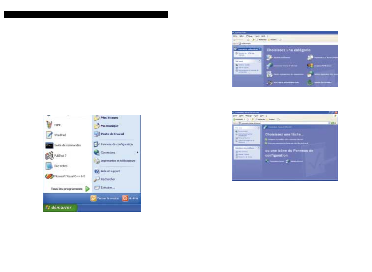
5352
Routeur de point d’accès sans fil avec commutateur 4 ports
Instant Wireless™ Series
2. Dans la fenêtre « Panneau de configuration », cliquez sur l’icône Connexions
réseau et Internet (figure C-4).
3. Cliquez sur l’icône Connexions réseau (figure C-5).
4. La fenêtre « Connexions réseau » apparaît (figure C-6). Sous Réseau local ou
Internet à haute vitesse sont répertoriées toutes les cartes réseau installées et util-
isées dans votre ordinateur. Double-cliquez sur l’icône Connexion réseau sans fil
associée à votre adaptateur sans fil.
Si la fenêtre « État de la connexion du réseau sans fil » apparaît, passez à l’étape
suivante.
Figure C-4
Figure C-5
Windows XP ne permettant pas l’utilisation de la fonction « phrase de passe » Linksys
avec les adaptateurs PC sans fil, vous devez entrer manuellement la clé générée dans la
section précédente.
Les instructions suivantes indiquent comment activer le cryptage WEP et entrer la clé
de cryptage manuellement pour vos cartes PC sans fil afin de permettre au système
Windows XP d’établir une communication sans fil avec le routeur.
Ces instructions partent du principe que votre lecteur de CD-ROM correspond à la let-
tre d’unité D et que vous utilisez Windows XP dans le mode par défaut.
Vérifiez que la clé WEP est générée par le routeur.
1. Dans le menu Démarrer, choisissez Panneau de configuration (figure C-3).
Figure C-3
Configuration de la sécurité sans fil dans Windows XP
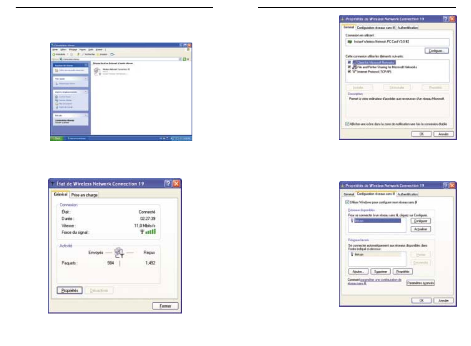
5554
Routeur de point d’accès sans fil avec commutateur 4 ports
Instant Wireless™ Series
6.
Lorsque la fenêtre « État de
la connexion du réseau
sans fil » apparaît (figure
C-8), cliquez sur l’onglet
Configuration réseaux
sans
fil.
7. Si le réseau sans fil appro-
prié, spécifié par le SSID
du routeur, est affiché dans
la section
«
Réseaux favoris »
(figure C-9), double-cliquez
dessus et passez à l’étape
suivante.
Sinon, cliquez sur le
réseau sans fil approprié,
spécifié par le SSID du
routeur, dans la section
«
Réseaux disponibles ».
Cliquez ensuite sur le bou-
ton Configurer.
Figure C-8
Figure C-9
Si une fenêtre « Connexion à un réseau sans fil » apparaît, dans la section Réseaux
disponibles, cliquez sur le réseau sans fil concerné, spécifié par le SSID du routeur.
Double-cliquez ensuite sur l’icône Connexion réseau sans fil.
5. Lorsque la fenêtre « État de la connexion du réseau sans fil » apparaît (figure C-7),
cliquez sur le bouton Propriétés.
Figure C-6
Figure C-7
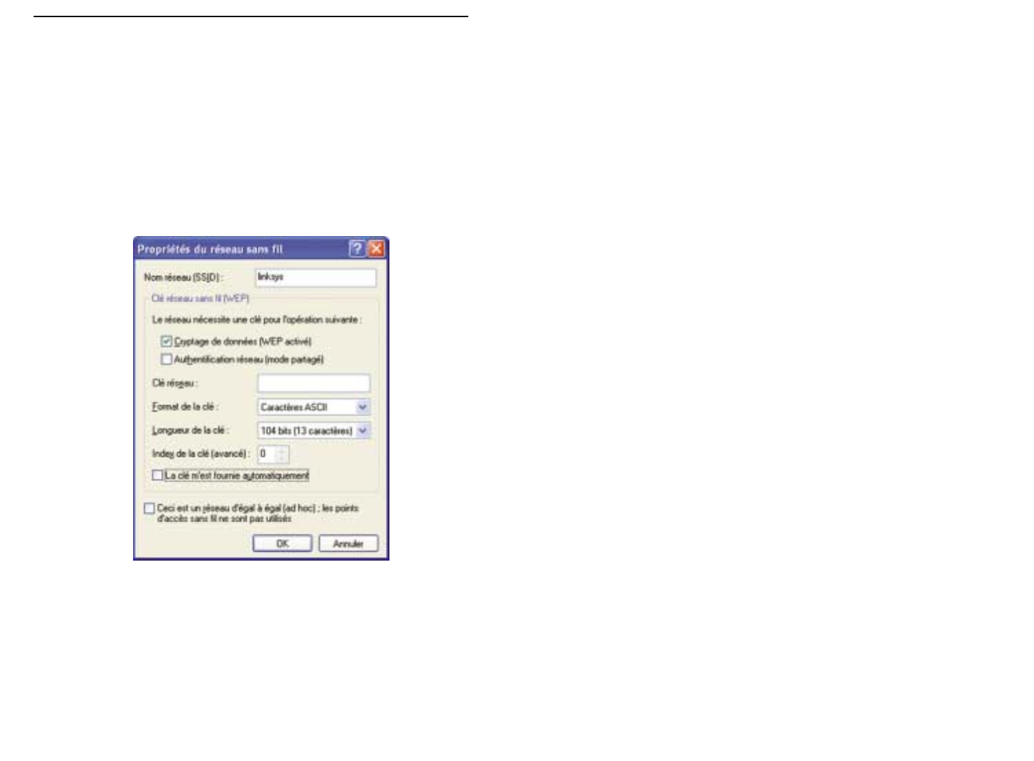
5756
Instant Wireless™ Series
8. La fenêtre
«
Propriétés du réseau sans fil
»
(figure C-10) apparaît.
Activez la case à cocher Cryptage de données (WEP activé).
Désactivez les cases à cocher Authentification réseau (mode partagé) et La clé
m’est fournie automatiquement.
Dans le champ
«
Clé réseau
»
, entrez la clé exacte (tous les 10 ou 26 chiffres, selon
le niveau de cryptage) générée par le routeur.
Vérifiez que le champ « Format de la clé » contient « Chiffres hexadécimaux » et
que le champ « Longueur de la clé » contient « 40 bits (10 chiffres) » ou « 104 bits
(26 chiffres)
»
. Si tel n’est pas le cas, vous n’avez pas entré la clé correctement.
Cliquez sur le bouton OK pour enregistrer les paramètres. Cliquez sur les boutons
OK jusqu’à ce que vous reveniez à la fenêtre
«
État de la connexion réseau sans fil
»
.
Fermez toutes les fenêtres pour revenir au bureau de Windows XP.
Fermez toutes les applications et redémarrez le PC. Après le redémarrage, la configuration
WEP est terminée et vous devriez pouvoir établir une connexion sans fil au routeur.
Figure C-10

5958
COPYRIGHT UND MARKEN Copyright © 2002 Linksys. Alle Rechte vorbehalten. Instant
Wireless ist eine Marke von Linksys. Microsoft, Windows und das Windows-Logo sind
eingetragene Marken der Microsoft Corporation. Alle anderen Marken und
Markennamen sind Eigentum der jeweiligen Firmen.
FCC-KONFORMITÄTSERKLÄRUNG Der Instant Wireless™ Wireless Access Point-Router
mit 4-Port-Switch wurde nach Maßgabe der Grenzwerte von Abschnitt 15 der FCC-
Vorschriften geprüft und als digitales Gerät der Klasse B eingestuft. Zweck dieser
Grenzwerte ist es, für angemessenen Schutz vor schädlichen Störungen im Umfeld einer
Privatinstallation zu sorgen. Dieses Gerät erzeugt und verwendet Funkfrequenzenergie
und kann diese ausstrahlen. Bei unsachgemäßer Installation und Verwendung kann es
Störungen des Funkverkehrs verursachen. Es kann nicht grundsätzlich ausgeschlossen
werden, dass in bestimmten Installationen Störungen auftreten. Für den Fall, dass das
Gerät Störungen des Funk- oder Fernsehempfangs auslöst, die sich durch Aus- und
Einschalten des Geräts feststellen lassen, wird dem Benutzer empfohlen, die Störung
durch eine oder mehrere der folgenden Maßnahmen zu beseitigen:
• Antenne neu ausrichten oder an einem anderen Ort aufstellen
• Abstand zum Empfänger oder Gerät erhöhen
• Empfänger und Gerät an getrennten Stromkreisen anschließen
• Händler oder erfahrenen Radio/TV-Fachmann hinzuziehen
Inhaltsverzeichnis
Einführung 61
Schritt 1: Anschließen des Routers 62
Schritt 2: Konfigurieren der PCs 64
Schritt 3: Konfigurieren des Routers 68
Hilfe 72
Konfigurieren der Wireless-Sicherheit 77
Konfigurieren der Wireless-Sicherheit unter
Windows XP 80
Produktunterstützung erhalten Sie unter den folgenden Adressen:
E-mail europe-support@linksys.com
latam-soporte@linksys.com
Web http://www.linksys.com/international
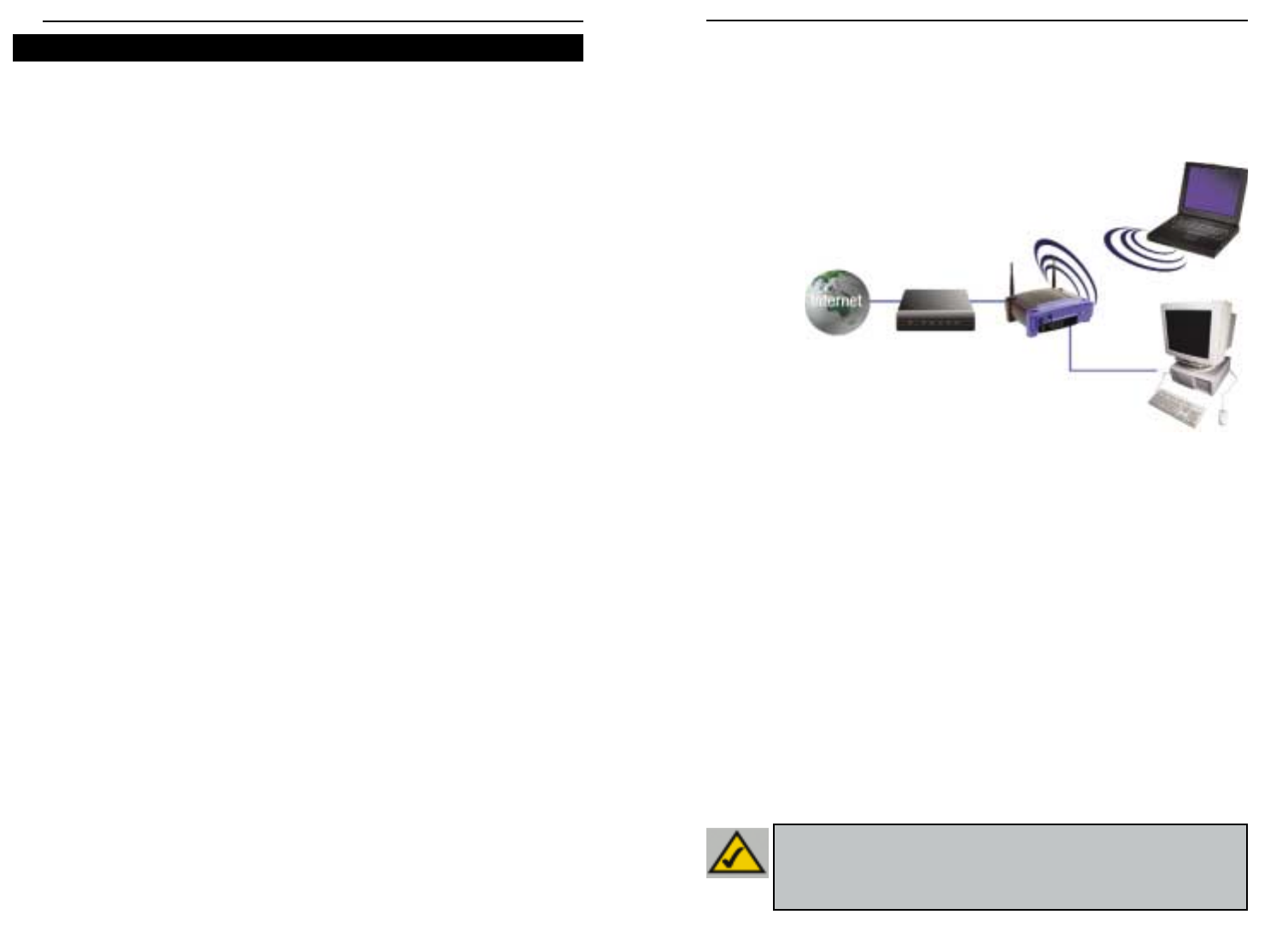
6160
Die Anweisungen in dieser Kurzanleitung helfen Ihnen, den Router anzuschließen,Ihre PCs zu
konfigurieren und den Router in Ihrem Netzwerk einzurichten. Diese Anweisungen sollten
ausreichen, um ein einfaches Netzwerk mit freigegebenem Internetzugriff in Betrieb zu
nehmen. Der Router verfügt auch über erweiterte Funktionen,die jedoch ein entsprechendes
Fachwissen über Router und Netzwerke voraussetzen. Diese und andere Themen werden im
Benutzerhandbuch behandelt,das sich auf der CD des Setup-Assistenten befindet.
Das Setup des
Routers ist dem
in der oben ste-
henden Abbildung für Windows-PCs gezeigten Setup vergleichbar. Mit dem Router können Sie
Ihre Kabel- oder DSL-Verbindung für mehrere Computer in Ihrem privaten oder geschäftlichen
Umfeld freigeben. Eine solche Struktur wird LAN (Local Area Network) genannt.
Diese Kurzanleitung vermittelt eine Übersicht der Komponenten zur Einrichtung eines ein-
fachen privaten oder geschäftlichen Netzwerks. In den nächsten drei Abschnitten erfahren
Sie, wie Sie Ihre Geräte einrichten und konfigurieren müssen, um über einen gemeinsamen
Hochgeschwindigkeitszugang zum Internet zu verfügen.
Schritt 1: Anschließen des Routers
In diesem Schritt schließen Sie den Router an Ihr Kabel- oder DSL-Modem an. Anschließend
verbinden Sie Ihre PCs mit dem Router.
Schritt 2: Konfigurieren der PCs
Hier ist beschrieben, wie Sie Ihre PCs konfigurieren müssen,um mit dem Router zu kommu-
nizieren.
Schritt 3: Konfigurieren des Routers
In diesem Schritt lernen Sie grundlegende Einstellungen des Routers kennen,die den Betrieb
mit Ihrem Kabel- oder DSL-Modem und Ihren ISP-Einstellungen ermöglichen.
Wireless Access Point-Router mit 4-Port-Switch
Instant Wireless™-Serie
Vielen Dank für die Wahl des Instant Wireless™ Wireless Access Point-Routers. Dieser
Router ermöglicht Ihnen die Einrichtung eines Netzwerks mit Ihren PCs sowie die Freigabe
Ihrer Internet-Verbindung im Netzwerk.
Wie kann der Router diese Funktionen erfüllen? Wenn Sie Ihr Kabel- oder DSL-Modem
direkt mit dem Router verbinden und Ihre PCs an den Ethernet-Ports des Routers
anschließen,ist die Wirkung dieselbe,als wäre jeder PC direkt mit dem Internet verbunden.
Auf diese Weise können mehrere PCs gleichzeitig eine Internet-Verbindung verwenden. Da
der Router zugleich ein Access Point ist, kann er Ihr Ethernet-Netzwerk mit Ihren kabellosen
PCs als Bridge verbinden.
Was bedeutet das?
Netzwerke sind ein wirkungsvolles Mittel zur gemeinsamen Nutzung von
Computerressourcen. Über Netzwerke können Sie beispielsweise von verschiedenen
Computern aus auf einen Drucker zugreifen und mit Daten arbeiten, die sich auf der
Festplatte eines anderen Computers befinden. Netzwerke werden sogar dazu verwendet,
Videospiele mit mehreren Spielern zu ermöglichen. Sie sind also nicht nur für die Arbeit
zuhause und im Büro,sondern auch für die Freizeit nützlich.
Die PCs, die Sie an die vier LAN-Ports des Routers anschließen, bilden bei richtiger
Konfiguration ein so genanntes LAN (Local Area Network), d. h. ein Nahbereichsnetzwerk.
Sie sind über Ethernet-Kabel verbunden, die jeweils an den Ethernet-Karten der Computer
und an den von 1 bis 4 nummerierten LAN-Ports des Routers angeschlossen sind. Der
Begriff „Ethernet“, mit dem Netzwerkkomponenten wie Kabel und Netzwerkkarten be-
zeichnet werden, weist darauf hin, dass Ethernet der Typ des Netzwerks ist, das Sie einrichten
.
In der Dokumentation des Routers bezeichnet „Ethernet“ alle Netzwerkkomponenten, die
Computerdaten mit 10 bis 100 Mbit/s übertragen. (10 und 100 Mbit/s sind die von den
Netzwerkgeräten verwendeten Übertragungsraten. Wenn Daten mit 10 Mbit/s übertragen
werden, entspricht dies dem Inhalt von mehr als sieben Disketten pro Sekunde!
Netzwerkkomponenten, die mit 100 Mbit/s arbeiten, transportieren die Daten sogar noch
zehnmal schneller!)
PCs können mit dem Router auch kabellos kommunizieren. Wenn Sie Ihre kabellosen PCs
und den Router mit denselben Wireless-Einstellungen konfigurieren, können Sie diese
kabellosen PCs in Ihr vorhandenes Ethernet-Netzwerk einbinden.
Ein besonders interessanter Aspekt ist, dass der Router die gemeinsame Nutzung Ihrer
Kabel- oder DSL-Internetverbindung ermöglicht. Hierzu müssen Sie lediglich Ihr Kabel- oder
DSL-Modem über ein Ethernet-Kabel an den WAN-Port des Routers anschließen. (WAN ist
die Abkürzung von „Wide Area Network“, d. h. Weitbereichsnetzwerk.) Das Internet weist
als globales Netzwerk die größte Ausdehnung aller Netzwerke auf! Die an den Router
angeschlossenen PCs können diese Verbindung nutzen.
Einführung
HHiinnwweeiiss::Diese Kurzanleitung beschreibt die Einrichtung des Routers mit Ethernet-
Kabeln. Der Router kann zwar auch über eine kabellose Verbindung eingerichtet wer-
den. In dieser Kurzanleitung werden jedoch keine Details zur kabellosen Einrichtung des
Routers beschrieben. Wenn Sie den Router über eine kabellose Verbindung einrichten
möchten, finden Sie weitere Informationen auf der Linksys-Website unter
www.linksys.com.
So sieht die fertig gestellte Struktur aus:

6362
In Schritt 1 verbinden Sie den Router mit Ihrem Kabel- oder DSL-Modem und Ihren priva-
ten oder geschäftlichen Computern.
Vergewissern Sie sich zunächst, dass alle Geräte ausgeschaltet sind, mit denen Sie arbei-
ten werden, also die PCs, das Modem und der Router.
A. Soweit Sie dies nicht bereits durchgeführt haben, schließen Sie jetzt Ihr Kabel- oder
DSL-Modem richtig an. Für den Kabelbetrieb ist eine Koaxialbuchse (Abbildung A1) und
für den DSL-Betrieb eine Telefonbuchse vorgesehen (Abbildung A2). (Folgen Sie den
Anweisungen im Installationshandbuch Ihres Kabel- oder DSL-Modems.)
Instant Wireless™-Serie
B. Verbinden Sie mit einem Ethernet-Kabel den
LAN- bzw. Ethernet-Port des Kabel- oder
DSL-Modems mit dem WAN-Port des
Routers.
C. Schließen Sie ein Ethernet-Kabel
an die Ethernet-Karte Ihres PCs
an. Schließen Sie das andere
Ende des Kabels an einen LAN-
Port des Routers an. Wiederholen
Sie diesen Vorgang für jeden
weiteren PC, den Sie an den
Router anschließen möchten.
Hinweis: Ist die Ethernet-Karte Ihres PCs nicht eingerichtet, finden Sie weitere
Informationen in der Dokumentation der Ethernet-Karte.
Um die Installation zu vereinfachen,beginnen
Sie mit dem LAN-Port 1 des Routers.
Schließen Sie anschließend Port 2, Port 3 und
schließlich Port 4 an.
Wenn Sie mehr als vier PCs an den Router
anschließen möchten, müssen Sie an den
Uplink-Port des Routers einen Hub oder
Switch anschließen (wenn Sie den Uplink-
Port verwenden, ist Port 4 nicht verfügbar).
Weitere Informationen zum Uplink-
Verfahren finden Sie im Benutzerhandbuch
auf der CD des Setup-Assistenten.
D. Verbinden Sie das Netzgerät mit dem Stromversorgungsanschluss des Routers.
Schließen Sie das Netzgerät an einer Netzsteckdose an. Schalten Sie das Kabel- oder
DSL-Modem ein. Schalten Sie dann den ersten PC ein, den Sie zum Konfigurieren des
Routers verwenden möchten.
Fahren Sie mit Schritt 2 fort: Konfigurieren Sie die PCs (siehe nächste Seite).
Wireless Access Point-Router mit 4-Port-Switch
A1A2
Schritt 1: Anschließen des Routers
B
C1
C2
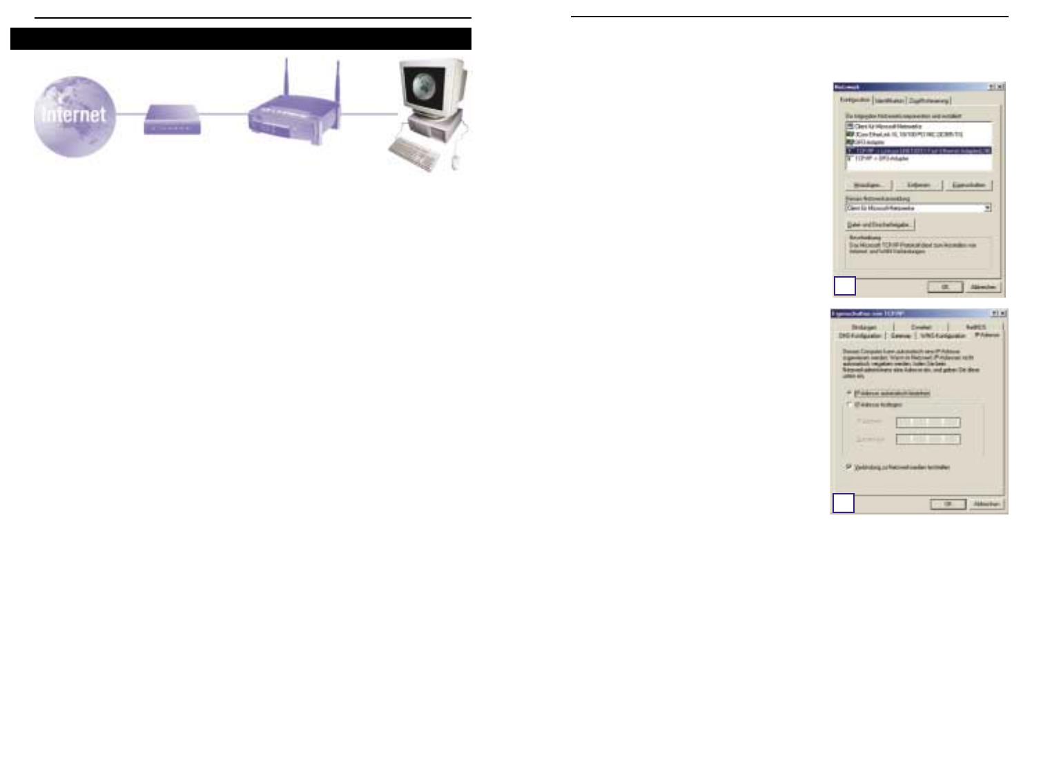
6564
In Schritt 2 werden Sie die einzelnen Computer für die Kommunikation mit dem Router kon-
figurieren.
Hierzu müssen Sie die Netzwerkeinstellungen Ihres PCs so einstellen,dass eine IP-Adresse
(auch TCP/IP-Adresse genannt) automatisch bezogen wird. Computer verwenden IP-
Adressen zur gegenseitigen Kommunikation über ein Netzwerk oder das Internet.
Ermitteln Sie,unter welchem Betriebssystem Ihr Computer läuft,z. B. unter Windows 95,98,
Millennium, 2000 oder XP. Sie müssen den Typ des verwendeten Betriebssystems kennen,
um fortzufahren. Hierzu können Sie auf die Schaltfläche Start klicken und anschließend die
Option Einstellungen auswählen. (Wenn Ihr Startmenü die Option Einstellungen nicht
enthält, handelt es sich um Windows XP. Hier können Sie die Systemsteuerung direkt aus
dem Startmenü wählen.) Doppelklicken Sie dann auf Systemsteuerung, und klicken Sie
auf das Symbol System. Klicken Sie auf die Schaltfläche Abbrechen, wenn Sie fertig sind.
Nachdem Sie jetzt wissen, welches Windows-Betriebssystem Sie verwenden, folgen Sie in
diesem Schritt den Anweisungen für das Betriebssystem Ihres Computers. Diesen Vorgang
müssen Sie gegebenenfalls für jeden Computer wiederholen, den Sie mit dem Router
verbinden.
Auf den nächsten Seiten erfahren Sie Schritt für Schritt, wie Sie Ihre TCP/IP-Einstellungen
für das verwendete Windows-Betriebssystem konfigurieren. Nachdem Sie die Konfiguration
Ihrer Computer abgeschlossen haben, fahren Sie mit Schritt 3 fort: Konfigurieren des
Routers
A. Klicken Sie auf die Schaltfläche Start, klicken
Sie auf Einstellungen, und öffnen Sie die
Systemsteuerung. Doppelklicken Sie hier auf
das Symbol Netzwerk, um das Fenster
Netzwerk zu öffnen.
B. Wählen Sie die Registerkarte Konfiguration
aus, und markieren Sie Zeile TCP/IP für die
entsprechende Ethernet-Karte*. Wenn das
Wort TCP/IP separat angezeigt wird, wählen
Sie diese Zeile aus**. Klicken Sie anschließend
auf die Schaltfläche Eigenschaften.
C. Klicken Sie auf die Registerkarte IP-Adresse,
und wählen Sie die Option IP-Adresse
automatisch beziehen.
D. Klicken Sie auf die Registerkarte Gateway,und
vergewissern Sie sich, dass das Feld
Installierte Gateways leer ist. Klicken Sie auf
die Schaltfläche OK.
E. Klicken Sie erneut auf die Schaltfläche OK.
Möglicherweise werden Sie nun vom System
nach den Original-Installationsdateien von
Windows oder nach zusätzlichen Dateien
gefragt. Geben Sie den richtigen Dateipfad für
diese Ressourcen an, z. B. „D:\win98“,
„D:\win9x“,„C:\Windows\Options\cabs“ usw. (hierbei wird angenommen,dass „D“ der
Laufwerkbuchstabe Ihres CD-ROM-Laufwerks ist).
F. Wenn Sie vom System gefragt werden, ob Sie Ihren PC neu starten möchten,klicken Sie
auf die Schaltfläche Ja. Führen Sie den Neustart in jedem Fall durch, auch wenn Sie
hierzu nicht aufgefordert werden.
*Hinweis: Wählen Sie keinen TCP/IP-Eintrag, dessen Name die Zeichenfolgen „DUN“,
„PPPoE“, „VPN“ oder „AOL“ enthält.
**
Hinweis: Ist keine TCP/IP-Zeile aufgelistet, sehen Sie im Benutzerhandbuch auf der Setup-CD
des Assistenten oder in der Dokumentation Ihrer Ethernet-Karte nach, wie Sie TCP/IP
jetzt installieren.
Instant Wireless™-Serie Wireless Access Point-Router mit 4-Port-Switch
Schritt 2: Konfigurieren der PCs Betriebssystem:
Windows 95, Windows 98, Windows Me
B
C
6766
Die folgenden Anweisungen setzen voraus, dass Sie
die Standardoberfläche von Windows XP verwen-
den. Wenn Sie die klassische Oberfläche verwenden
(bei der die Symbole und Menüs wie in den vorheri-
gen Windows-Versionen aussehen), folgen Sie den
Anweisungen für Windows 2000.
A. Klicken Sie auf die Schaltfläche Start, öffnen
Sie die Systemsteuerung, und klicken Sie auf
das Symbol Netzwerk- und
Internetverbindungen. Klicken Sie dann auf
das Symbol Netzwerkverbindungen, um das
Fenster Netzwerk zu öffnen.
B. Wählen Sie das Symbol LAN-Verbindung für
die entsprechende Ethernet-Karte aus (in der
Regel ist dies die erste aufgelistete LAN-
Verbindung). Doppelklicken Sie auf LAN-
Verbindung.
C. Wenn das Statusfenster für die LAN-Verbindung
angezeigt wird, klicken Sie auf die Schaltfläche
Eigenschaften.
D. Wählen Sie Internetprotokoll (TCP/IP),und kli-
cken Sie auf die Schaltfläche Eigenschaften.
E. Wählen Sie IP-Adresse automatisch
beziehen, und klicken Sie in den folgenden
Dialogfeldern auf die Schaltfläche OK, um die
Konfiguration des PCs abzuschließen.
F. Starten Sie Ihren Computer neu.
A. Klicken Sie auf die Schaltfläche Start, klicken
Sie auf Einstellungen, und öffnen Sie die
System-steuerung. Doppelklicken Sie hier auf
das Symbol Netzwerk- und DFÜ-
Verbindungen. Hierdurch wird das Fenster
Netzwerk geöffnet.
B. Wählen Sie das Symbol LAN-Verbindung für die
entsprechende Ethernet-Karte* aus (in der Regel
ist dies die erste aufgelistete LAN-Verbindung).
Doppelklicken Sie auf LAN-Verbindung.
C. Wenn das Statusfenster für die LAN-Verbindung
angezeigt wird, klicken Sie auf die Schaltfläche
Eigenschaften.
D. Wählen Sie Internetprotokoll (TCP/IP),und kli-
cken Sie auf die Schaltfläche Eigenschaften.
E. Wählen Sie IP-Adresse automatisch beziehen,
und klicken Sie in den folgenden Dialogfeldern
auf die Schaltfläche OK, um die Konfiguration
des PCs abzuschließen.
F. Starten Sie Ihren Computer neu.
*Hinweis: Wählen Sie keinen TCP/IP-Eintrag, dessen
Name die Zeichenfolgen „DUN“, „PPPoE“, „VPN“
oder „AOL“ enthält.
Instant Wireless™-Serie Wireless Access Point-Router mit 4-Port-Switch
Betriebssystem:
Windows 2000
E
D
C
Betriebssystem:
Windows XP
C
D
E
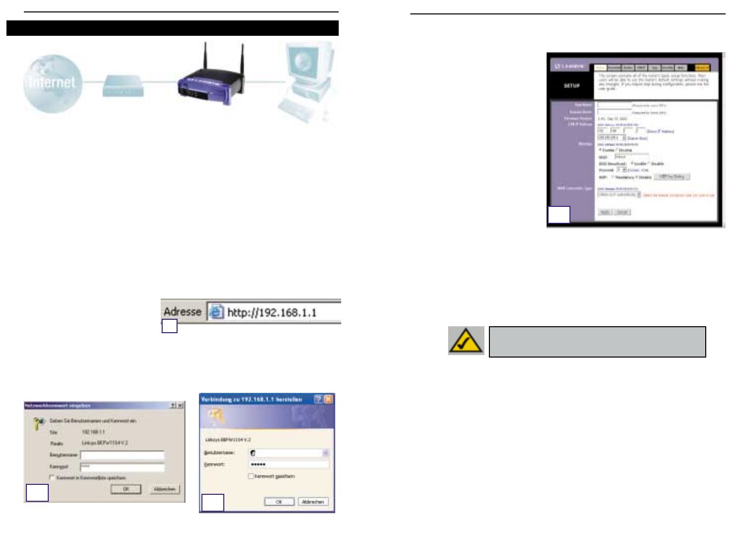
6968
C. Sofern dies von Ihrem ISP vorgeschrieben wird, geben Sie den Hostnamen und den
Domänennamen des Routers in den entsprechenden Feldern Host Name und Domain
Name der Registerkarte Setup ein (dies ist üblicherweise bei Kabel-ISPs der Fall).
D. Um den Router für Ihr kabelloses
Netzwerk zu konfigurieren, verge-
wissern Sie sich, dass die
Wireless-Felder auf der Regis-
terkarte Setup (siehe Abbildung
D) wie folgt ausgefüllt sind:
Enable/Disable
(Aktivieren/Deaktivieren):
Durch
Auswahl des Optionsfelds Enable
(Aktivieren) werden die Wireless-
Funktionen des Routers aktiviert.
Die Wireless-Funktionen sind nur
nach Aktivierung verfügbar.
SSID: Die SSID (bzw. ESSID) ist ein
eindeutiger Name für Ihr kabel-
loses Netzwerk. Er darf maximal
32 Zeichen umfassen; die Groß-/Kleinschreibung wird berücksichtigt. Die Standard-
SSID lautet „linksys“. Sie sollten diese jedoch auf einen persönlichen Netzwerknamen
ändern. Alle Wireless Access Points in Ihrem Netzwerk müssen dieselbe SSID verwen-
den.
Channel (Kanal): Wählen Sie den entsprechenden Kanal für Ihr Netzwerk aus der
angezeigten Liste. Alle Wireless Access Points in Ihrem Netzwerk müssen denselben
Kanal verwenden, um einwandfrei zu funktionieren.
E. Der Router unterstützt fünf Verbindungstypen: DHCP (automatischer Bezug der IP-
Adresse), PPPoE, statische IP-Adresse, RAS und PPTP. Diese Typen können aus dem
Pulldownmenü neben WAN Connection Type (WAN-Verbindungstyp) ausgewählt wer-
den. Abhängig von Ihrer Auswahl des Verbindungstyps wird ein entsprechender Setup-
Bildschirm mit spezifischen Funktionen angezeigt. Die Anweisungen hierzu finden Sie
nachfolgend:
1. Obtain an IP Automatically (IP-Adresse automatisch beziehen)
Wenn Ihr ISP vorschreibt, dass Sie eine Verbindung über eine dynamische IP-Adresse (oder
DHCP) herstellen sollen, führen Sie diese Schritte aus:
a. Wählen Sie für den WAN-Verbindungstyp die Option Obtain an IP automatically (IP-
Adresse automatisch beziehen), wie zuvor in Abbildung D gezeigt.
b. Klicken Sie auf die Schaltfläche Apply (Übernehmen) um die Einstellungen zu speich-
ern.
In Schritt 3 konfigurieren Sie den Router für Ihr Netzwerk und richten den Internetzugang
über Ihren Internetdienstanbieter (ISP) ein. Ihr ISP schreibt möglicherweise die Verwendung
eines Hostnamens und eines Domänennamens vor. Außerdem legen Sie den WAN-
Konfigurationstyp auf der Registerkarte Setup des Routers nach den Setup-Informationen
Ihres ISP fest.
Diese Setup-Informationen müssen Ihnen vorliegen.
Sollte dies nicht der Fall
sein, wenden Sie sich an Ihren ISP, bevor Sie fortfahren. Die richtigen Fragestellungen an
Ihren ISP finden Sie in Frage Nr. 1 im Hilfeabschnitt.
Die Anweisungen Ihres ISP beschreiben,wie Sie Ihren PC für den Internetzugriff einrichten.
Da Sie jetzt den Router zur gemeinsamen Nutzung des Internetzugangs durch mehrere
Computer verwenden, werden diese Setup-Informationen für die Router-Konfiguration
benötigt.
A. Öffnen Sie Ihren Webbrowser. (Wenn Sie an diesem Punkt eine Fehlermeldung erhalten,
können Sie diese ignorieren. Fahren Sie den Anweisungen entsprechend fort.) Geben
Sie im Adressfeld des Web-
browsers 192.168.1.1 ein, und
drücken Sie die EINGABETASTE.
B. Nun wird ein Fenster zur Eingabe
des Netzwerkkennworts angezeigt (siehe Abbildung B1). Unter Windows XP wird das
Fenster Verbinden mit 192.168.1.1 angezeigt (siehe Abbildung B2.). Lassen Sie das
Feld Benutzername leer, und geben Sie im Feld Kennwort das Standardkennwort
admin in Kleinbuchstaben ein. Klicken Sie anschließend auf die Schaltfläche OK.
Instant Wireless™-Serie Wireless Access Point-Router mit 4-Port-Switch
Schritt 3: Konfigurieren des Routers
A
B1B2
D
HHiinnwweeiiss:: Wenn Sie die WEP-Einstellungen des Routers
ändern möchten, fahren Sie mit dem Abschnitt zum
Konfigurieren der Wireless-Sicherheit fort.
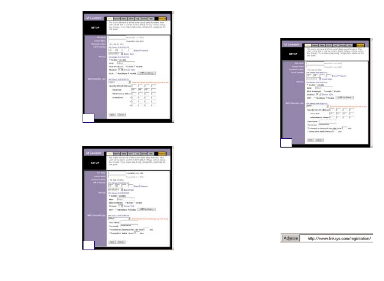
7170
Wireless Access Point-Router mit 4-Port-Switch
4. RAS
RAS ist ein Dienst,der nur in Singapur verwendet wird. Wenn Sie eine RAS-Verbindung ver-
wenden, fragen Sie Ihren ISP nach den erforderlichen Setup-Informationen.
5. PPTP
PPTP ist ein Dienst, der nur in Europa
verwendet wird. Wenn Sie eine PPTP-
Verbindung verwenden, fragen Sie
Ihren ISP nach den erforderlichen
Setup-Informationen.
F. Soweit Sie dies nicht bereits durchgeführt haben, klicken Sie jetzt auf die Schaltfläche
Apply (Übernehmen) um die Einstellungen zu speichern.
G. Schalten Sie das Kabel- oder DSL-Modem aus und wieder ein, und starten Sie Ihre
Computer neu. Damit übernehmen diese Geräte jetzt die neuen Einstellungen des
Routers.
Hinweis:Der Router muss nur von einem Computer aus konfiguriert werden. Erweiterte
Setup-Informationen finden Sie auf der Support-Website von Linksys unter
support.linksys.com
oder im Benutzerhandbuch auf der CD des Setup-Assistenten.
Das Setup ist beendet! Der Router ist nun vollständig konfiguriert. Sie können das Setup
testen, indem Sie Ihren Webbrowser auf einem der Computer öffnen und
www.linksys.com/registration
eingeben.
Wenn Sie diese Website nicht öffnen können, sollten Sie die einzelnen Schritte in
diesem Abschnitt noch einmal überprüfen oder im Hilfeabschnitt dieser Kurzanleitung
nachschlagen.
Instant Wireless™-Serie
2. Statische IP-Adresse
Wenn Ihr ISP vorschreibt, dass Sie eine
Verbindung über eine statische
(unveränderliche) IP-Adresse herstellen
sollen, führen Sie diese Schritte aus:
a. Wählen Sie als WAN-Verbin-
dungstyp die Option Static IP
(statische IP-Adresse).
b. Geben Sie in den Feldern neben
Specify WAN IP Address (IP-
Adresse angeben) die IP-Adresse ein.
c. Geben Sie unter Subnet Mask die
Subnetmask ein.
d. Geben Sie unter Default Gateway
Address die Standard-Gateway-
adresse ein.
e. Geben Sie unter DNS die DNS-
Adresse in den Feldern 1,2 bzw. 3
ein. Sie müssen mindestens eine
DNS-Adresse eingeben.
f. Klicken Sie auf die Schaltfläche Apply (Übernehmen) um die Einstellungen zu speichern.
3. PPPoE
Wenn Ihr DSL-Anbieter vorschreibt,
dass Sie eine Verbindung über PPPoE
herstellen, oder wenn Sie üblicher-
weise einen Benutzernamen und ein
Kennwort eingeben, um auf das
Internet zuzugreifen, führen Sie diese
Schritte aus:
a. Wählen Sie als WAN-Verbin-
dungstyp die Option PPPoE.
b. Geben Sie unter User Name den
Benutzernamen ein.
c. Geben Sie unter Password das
Kennwort ein.
d. Klicken Sie auf die Schaltfläche
Apply (Übernehmen)
um die
Einstellungen zu speichern.
e. Klicken Sie auf die Registerkarte
Status und anschließend auf die Schaltfläche Connect (Verbinden), um die Verbindung
herzustellen.
E2
E3
E5

7372
Wireless Access Point-Router mit 4-Port-Switch
2. Ich habe Probleme beim Herstellen einer Verbindung zum Internet. Welche der
LEDs an der Vorderseite des Routers sollen leuchten?
•Eine leuchtende Router-LED zeigt jeweils an, dass die zugehörige Verbindung an der
Rückseite des Routers einwandfrei ist, gleich ob es sich dabei um das Ethernet-Kabel
oder um die Stromversorgung handelt.
Beispielsweise leuchten üblicherweise die folgenden LEDs,nachdem ein Computer und
ein Kabel- oder DSL-Modem angeschlossen wurde:
- Wenn der Router eingeschaltet ist (wenn also das Netzteil am Router
angeschlossen ist), leuchtet die LED
Power
.
- Wenn ein Ethernet-Kabel an Port 4 des Routers und an einen PC richtig
angeschlossen ist, leuchten die LEDs
Link/Act
,
Ful/Col
und
100
in Spalte 4.
- Der Anschluss eines Kabel- oder DSL-Modems bewirkt das Aufleuchten der LED
WAN Link
.
Instant Wireless™-Serie
Im Hilfeabschnitt finden Sie die am häufigsten gestellten Fragen zu Internetverbindungen.
Wenn Sie zusätzliche Optionen festlegen möchten oder Informationen zu den erweiterten
Funktionen benötigen, besuchen Sie
kb.linksys.com
, oder schlagen Sie im
Benutzerhandbuch nach, das einen Anhang zur Fehlerbehebung enthält (es befindet sich
auf der CD des Setup-Assistenten).
1. Ich bin mir nicht sicher, welche Informationen ich von meinem
Internetdienstanbieter (ISP) benötige, um mein Netzwerk in Betrieb nehmen zu
können. Welche Fragen muss ich stellen?
Welchen Verbindungstyp verwenden Sie:dynamische IP-Adresse,statische IP-Adresse oder
PPPoE?
•Wenn Sie eine dynamische IP-Adresse verwenden, benötigen Sie folgende Daten:
- Ihren Hostnamen (soweit erforderlich)
- Ihren Domänennamen (soweit erforderlich)
•Wenn Sie eine statische IP-Adresse verwenden, benötigen Sie folgende Daten:
- Ihre IP-Adresse
- Ihre Gateway-Adresse
- Ihre DNS-Adresse
•Wenn Sie PPPoE verwenden (üblich bei DSL-ISPs),benötigen Sie folgende Daten:
- Ihren Benutzernamen
- Ihr Kennwort
Nachdem Sie diese Informationen erhalten haben,folgen Sie den Anweisungen in Schritt 3
der Kurzanleitung:Konfigurieren Sie den Router,und verwenden Sie diese Informationen zur
Eingabe auf der Registerkarte Setup. Beziehen Sie sich für den Abschnitt WAN Connection
Type (WAN-Verbindungstyp) auf das Diagramm auf der nächsten Seite:
Hilfe ?Dynamische
IP-Adresse (DHCP) 1. Wählen Sie als WAN-Verbindungstyp die Option Obtain an IP
automatically (IP-Adresse automatisch beziehen).
2. Klicken Sie auf die Schaltfläche Apply (Übernehmen) um die
Einstellung zu speichern.
Führen Sie diese Schritte aus:
PPPoE 1. Wählen Sie als WAN-Verbindungstyp die Option PPPoE.
2. Geben Sie unter User Name den Benutzernamen ein.
3. Geben Sie unter Password das Kennwort ein.
4. Klicken Sie auf die Schaltflächen Apply (Übernehmen) um die
Einstellungen zu speichern.
Statische
IP-Adresse 1. Wählen Sie als WAN-Verbindungstyp die Option Static IP
(statische IP-Adresse).
2. Geben Sie unter IP Address die IP-Adresse ein.
3. Geben Sie unter Subnet Mask die Subnetmask ein.
4. Geben Sie unter Gateway Address die Gatewayadresse ein.
5. Geben Sie unter DNS die DNS-Adresse in den Feldern 1, 2
bzw. 3 ein. Sie müssen mindestens eine DNS-Adresse
eingeben.
6. Klicken Sie auf die Schaltfläche Apply (Übernehmen) um die
Einstellungen zu speichern.
RAS oder PPTP Wenn Sie RAS (Singapore SingTel) oder PPTP (einen europäischen
Dienst) verwenden, fragen Sie Ihren ISP nach den erforderlichen
Setup-Informationen.
Verbindungstyp:

7574
Wireless Access Point-Router mit 4-Port-Switch
•Das Feld IP-Adresse muss die IP-Adresse 192.168.1.100 bzw. 192.168.1.xxx
enthalten, wobei „xxx“ für eine Zahl größer 100 steht. Befindet sich Ihre IP-
Adresse nicht in diesem Bereich,drücken Sie die Reset-Taste an der Vorderseite
des Routers länger als 30 Sekunden. Hierdurch wird der Router auf die
Werksvorgabe zurückgesetzt, daher müssen Sie die Setup-Seite des Routers neu
konfigurieren. Führen Sie nach der Neukonfiguration der Setup-Seite einen
Neustart des Computers aus.
C. Anschließend konfigurieren Sie einige Einstellungen von Windows.
- Doppelklicken Sie auf dem Desktop auf Arbeitsplatz und dann auf Systemsteuerung
(bei Verwendung der Standardoberfläche von Windows XP klicken Sie auf Start und
wählen dann Systemsteuerung).
- Wenn das Fenster Systemsteuerung angezeigt wird, doppelklicken Sie auf das Symbol
Internetoptionen (bei Verwendung der Standardoberfläche von Windows XP klicken
Sie auf Netzwerk- und Internetverbindungen und dann auf Internetoptionen).
- Wenn das Fenster Internetoptionen angezeigt wird, klicken Sie auf die Registerkarte
Verbindungen.
- Aktivieren Sie die Option Keine Verbindung wählen. (Wenn diese Option abgeblendet
ist, müssen Sie nichts ändern.)
- Klicken Sie auf die Schaltfläche LAN-Einstellungen in der unteren rechten Ecke.
- Wenn das Fenster Einstellungen für lokales Netzwerk (LAN) angezeigt wird,deaktivieren
Sie alle Kontrollkästchen.
- Klicken Sie auf die Schaltfläche OK und anschließend auf die Schaltfläche
Übernehmen (wenn Sie keine Änderungen vornehmen mussten, ist die Schaltfläche
Übernehmen abgeblendet). Klicken Sie anschließend erneut auf die Schaltfläche OK.
- Schließen Sie die Systemsteuerung, und starten Sie Ihren Computer neu.
4. Wenn ich auf das Symbol für den Internetzugang klicke und die Benutzer-
name/Kennwort-Kombination eingebe, die mir mein ISP mitgeteilt hat, kann ich
keine Verbindung zum Internet herstellen. Was ist der Fehler?
Sie verwenden die von Ihrem ISP bereitgestellte Software. Verwenden Sie stattdessen
Internet Explorer bzw. Netscape Navigator. Diese Browser können Sie von Ihrem Desktop
aus (unter Windows XP aus dem Startmenü) aufrufen.
5. Wenn ich Internet Explorer verwende, wird ein Feld eingeblendet, dass zum
Herstellen einer DFÜ-Verbindung auffordert. Wie kann ich diese Einstellung
deaktivieren?
A. Doppelklicken Sie auf dem Desktop auf Arbeitsplatz und dann auf Systemsteuerung
(bei Verwendung der Standardoberfläche von Windows XP klicken Sie auf Start und
wählen dann Systemsteuerung).
B. Wenn das Fenster Systemsteuerung angezeigt wird,doppelklicken Sie auf das Symbol
Internetoptionen (bei Verwendung der Standardoberfläche von Windows XP klicken
Sie auf Netzwerk- und Internetverbindungen und dann auf Internetoptionen).
C. Wenn das Fenster Internetoptionen angezeigt wird, klicken Sie auf die Registerkarte
Verbindungen.
Instant Wireless™-Serie
•Die LED
WAN Link
leuchtet nicht. Was muss ich überprüfen?
-
Prüfen Sie, ob es sich bei dem Kabel zwischen dem Kabel- oder DSL-Modem und dem
Router um das mit dem Modem gelieferte Kabel handelt. Abhängig von dem
Verbindungstyp, den Ihr Modem verwendet, benötigen Sie entweder ein „ge-
rades“ oder ein „gekreuztes“ Ethernet-Kabel (das „gerade“ Kabel ist das üblichere).
•Nach dem Anschließen eines PCs leuchten einige der LEDs an der Vorderseite des
Routers nicht.
- Die einwandfreie Funktion einer Verbindung ist bereits gewährleistet, wenn nur
die LED
Link/Act
leuchtet.
3. Ich kann keine Verbindung zum Internet herstellen und nicht auf die Setup-Seite
des Routers zugreifen. Was muss ich überprüfen?
A. Prüfen Sie zunächst, ob das Kabel- oder DSL-Modem und die Computer richtig mit dem
Router verbunden sind. In der Antwort zur Frage Nr. 2 ist beschrieben, wie Sie diese
Verbindungen überprüfen.
B. Prüfen Sie dann, ob Sie die PCs richtig für die Kommunikation mit dem Router konfig-
uriert haben. Nachfolgend finden Sie Anweisungen hierzu für die verschiedenen
Versionen von Windows.
-Windows 95, 98 oder Me
•Klicken Sie auf das Menü Start und dann auf Ausführen. Wenn das Fenster
Ausführen angezeigt wird,geben Sie im Feld Öffnen die Zeichenfolge winipcfg
ein. Klicken Sie anschließend auf die Schaltfläche OK.
•Wenn das Fenster IP-Konfiguration angezeigt wird, klicken Sie auf das grau
unterlegte Feld mit dem schwarzen,nach unten weisenden Pfeil.
•Nun wird eine Liste mit Netzwerkkarten angezeigt. Wählen Sie die Karte aus,mit
der Sie die Verbindung zum Internet herstellen. Diese Karteneinträge dürfen nicht
die Zeichenfolgen „PPP“, „VPN“, „AOL“ oder „DFÜ-Adapter“ enthalten.
•Das Feld IP-Adresse muss die IP-Adresse 192.168.1.100 bzw. 192.168.1.xxx
enthalten, wobei „xxx“ für eine Zahl größer 100 steht. Befindet sich Ihre IP-
Adresse nicht in diesem Bereich,drücken Sie die Reset-Taste an der Vorderseite
des Routers länger als 30 Sekunden. Hierdurch wird der Router auf die
Werksvorgabe zurückgesetzt, daher müssen Sie anschließend die Setup-Seite
des Routers neu konfigurieren. Führen Sie nach der Neukonfiguration der Setup-
Seite einen Neustart des Computers aus.
-Windows NT, 2000 und XP
•Klicken Sie auf das Menü Start und dann auf Ausführen. Wenn das Fenster
Ausführen angezeigt wird, geben Sie im Feld Öffnen die Zeichenfolge cmd ein.
Klicken Sie anschließend auf die Schaltfläche OK.
•Hierdurch wird eine Eingabeaufforderung angezeigt. Geben Sie ipconfig /all ein,
und drücken Sie dann die Eingabetaste.
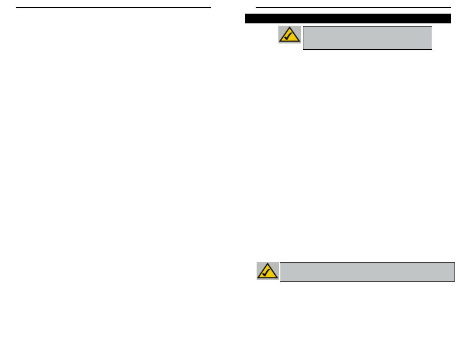
7776
Wireless Access Point-Router mit 4-Port-Switch
Instant Wireless™-Serie
D. Aktivieren Sie die Option Keine Verbindung wählen.
E. Klicken Sie auf die Schaltfläche Übernehmen.
F. Klicken Sie auf die Schaltfläche OK.
6. Es wird keine ausreichende Signalstärke oder Verbindungsqualität angezeigt;
was kann ich tun?
A. Vergewissern Sie sich, dass die WLAN-LED des Routers leuchtet.
B. Vergewissern Sie sich, dass alle Ihre kabellosen PCs den Infrastrukturmodus verwen-
den.
7. Wie kann ich die Betriebsreichweite des Routers verbessern?
A. Vergewissern Sie sich,dass der Router möglichst hoch über dem Boden aufgestellt ist.
B. Vergewissern Sie sich, dass sich in der Nähe keine großen elektrischen
Störungsquellen befinden (wie beispielsweise Lautsprecher, Schaltschränke,
Leuchtstoffröhren, Mikrowellengeräte usw.)
C. Wechseln Sie den verwendeten Wireless-Kanal. Hierzu gehen Sie wie folgt vor:
- Öffnen Sie Ihren Webbrowser, und geben Sie im Adressfeld http://192.168.1.1 ein.
- Lassen Sie im Dialogfeld Enter Network Password (Netzwerkkennwort eingeben) das
Feld User Name (Benutzername) leer, und geben Sie admin als Kennwort ein. Klicken
Sie anschließend auf OK.
- Ändern Sie auf der Registerkarte Setup den Kanal auf 1.
- Klicken Sie auf die Schaltfläche Apply (Übernehmen) um die Einstellungen zu speich-
ern.
- Wiederholen Sie diesen Vorgang,bis Sie den Kanal mit der besten Reichweite gefunden
haben.
WEP steht als Abkürzung für „Wired Equivalent Privacy“, ein Verschlüsse-
lungsverfahren zum Schutz Ihrer kabellosen Datenkommunikation. WEP verwendet
eine Kombination aus 64-Bit- oder 128-Bit-Schlüsseln, um den Zugriff auf das
Netzwerk zu kontrollieren und die einzelnen Datenübertragungen sicher zu verschlüs-
seln. Um eine Datenübertragung zu decodieren, muss jeder Access Point im Netzwerk
einen identischen 64-Bit- bzw. 128-Bit-Schlüssel verwenden. Höhere Verschlüsse-
lungsstärken gewährleisten zwar eine höhere Sicherheit, aufgrund der Komplexität der
Verschlüsselung können sie jedoch eine verminderte Netzwerkleistung bewirken.
Vielleicht haben Sie im Zusammenhang mit der WEP-Verschlüsselung auch den Begriff
„40-Bit“ gehört. Auch damit ist die 64-Bit-WEP-Verschlüsselung gemeint. Diese
WEP-Verschlüsselungsstufe wird „40-Bit“ genannt, weil sie einen geheimen 40-Bit-
Schlüssel zusammen mit einem 24-Bit-Initialisierungsvektor verwendet (40 + 24 = 64).
Die Hersteller von Wireless-Geräten verwenden beide Bezeichnungen. Linksys bezeich-
net diese Verschlüsselungsstufe mit „64-Bit“.
Vergewissern Sie sich, dass Ihr kabelloses Netzwerk funktioniert, bevor Sie versuchen,
die WEP-Verschlüsselung zu konfigurieren.
Ein nach dem 128-Bit-WEP-Verfahren verschlüsseltes kabelloses Netzwerk kann
NICHT mit einem nach dem 64-Bit-WEP-Verfahren verschlüsselten kabellosen
Netzwerk kommunizieren. Vergewissern Sie sich daher, dass alle Ihre kabellosen Geräte
die gleiche Verschlüsselungsstufe verwenden. Alle kabellosen Geräte, die der Norm
802.11b entsprechen, unterstützen 64-Bit-WEP.
Linksys empfiehlt nicht nur, WEP zu aktivieren, sondern darüber hinaus auch folgende
Sicherheitsmaßnahmen zu ergreifen:
•Ändern der SSID von der Vorgabe „linksys“
•Regelmäßiges Ändern des WEP-Schlüssels
Hinweis: Die WEP-Verschlüsselung ist ein zusätzliches
Mittel zur Datensicherheit und für die Funktion des
Routers nicht erforderlich.
Hinweis: Möchten Sie die WEP-Verschlüsselung aktivieren, müssen zuerst die Wireless-
Funktionen aktiviert sein. Wählen Sie auf der Registerkarte Wireless (Kabellos) des
Routers die Option Enable (Aktivieren), bevor Sie fortfahren.
Konfigurieren der Wireless-Sicherheit
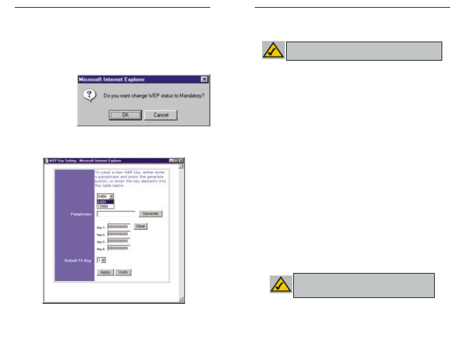
7978
Wireless Access Point-Router mit 4-Port-Switch
Instant Wireless™-Serie
• WEP (64-Bit oder 128-Bit) Wählen Sie die Verschlüsselungsstufe aus dem
Dropdownfeld. Die 128-Bit-WEP-Verschlüsselung von Linksys ist herstellerspezi-
fisch und möglicherweise nicht kompatibel mit der WEP-Verschlüsselung anderer
Hersteller.
Der WEP-Schlüssel wird nach einem der folgenden beiden Verfahren generiert:
1. Durch Verwendung eines Kennwortsatzes
a. Geben Sie einen Kennwortsatz als benutzerdefiniertes Kennwort in das Feld
Passphrase (Kennwortsatz) ein. Der Kennwortsatz kann bis zu 31 Buchstaben,
Sonderzeichen und Ziffern enthalten. Leerzeichen sind nicht zulässig.
b. Klicken Sie auf die Schaltfläche Generate (Generieren), um einen Schlüssel zu
erstellen. Wenn Sie die 64-Bit-Verschlüsselung gewählt haben, besteht der
Schlüssel aus 10 Ziffern, bei der 128-Bit-Verschlüsselung aus 26 Ziffern. Mit
diesem Schlüssel werden die zwischen dem Router und den kabellosen PCs des
Netzwerks übertragenen Daten verschlüsselt bzw. entschlüsselt.
Im Feld Key (Schlüssel) werden möglicherweise nicht alle Ziffern angezeigt. In
diesem Fall klicken Sie mit der Maus an eine beliebige Stelle in diesem Feld.
Verschieben Sie den Mauszeiger nach rechts, um den Rest des Schlüssels
anzuzeigen. Der gesamte Schlüssel muss exakt so übernommen werden, wie er
angezeigt wird.
2. Alternativ können Sie einen Schlüssel auch manuell eingeben.
Notieren Sie sich den Kennwortsatz bzw. den manuellen Schlüssel. Sie benötigen diese
Angaben für die anderen kabellosen Geräte im Netzwerk, da bei diesen immer derselbe
WEP-Schlüssel eingegeben werden muss.
Nachdem Sie das Verschlüsselungsverfahren ausgewählt und entweder den
Kennwortsatz oder einen manuellen Schlüssel eingegeben haben, klicken Sie auf die
Schaltfläche Apply (Übernehmen). Damit ist die Verschlüsselungskomponente des
Setup abgeschlossen.
Hinweis: Um die WEP-Verschlüsselung einsetzen zu können, muss diese bei
allen Access Points in Ihrem kabellosen Netzwerk aktiviert und auf dieselbe
Schlüsseleinstellung eingestellt sein.
Hinweis: Unter Windows XP wird der vom Router generierte 128-Bit-
Schlüssel „104-Bit-Schlüssel (26 Ziffern)“ genannt und der vom
Router generierte 64-Bit-Schlüssel heißt „40-Bit-Schlüssel
(10 Ziffern)“.
Die folgenden Schritte zeigen Ihnen, wie Sie die WEP-Verschlüsselung einsetzen.
1. Wählen Sie auf der Registerkarte Setup des Web-Dienstprogramms im Abschnitt
WEP die Option Mandatory (Obligatorisch).
2. Klicken Sie auf die Schaltfläche WEP Key Setting (WEP-Schlüsseleinstellung),
um den Typ und die Stufe der WEP-Verschlüsselung einzustellen.
3. Nun wird gegebenenfalls das in Abbildung C-1 dargestellte Dialogfeld angezeigt, in
dem bestätigt wird,
dass Sie die WEP-
Verschlüsselung
aktivieren. Klicken
Sie auf die Schalt-
fläche OK, um fort-
zufahren.
4. Nun wird das in
Abbildung C-2 dargestellte Dialogfeld angezeigt. Hier können Sie Ihre WEP-
Verschlüsselungseinstellungen wählen.
Abbildung C-2
Abbildung C-1
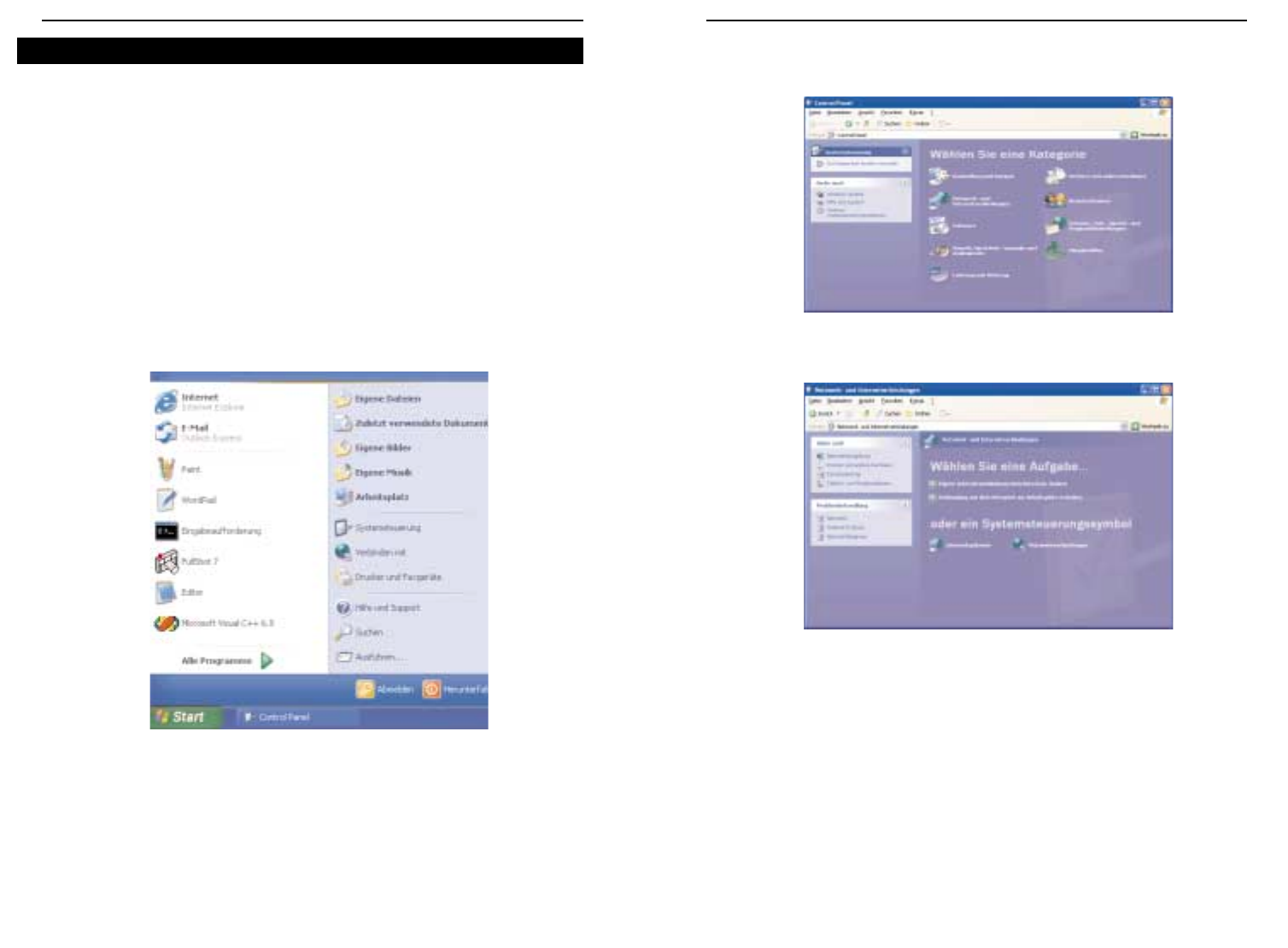
8180
Wireless Access Point-Router mit 4-Port-Switch
Instant Wireless™-Serie
2. Klicken Sie im Fenster Systemsteuerung auf das Symbol Netzwerk- und
Internetverbindungen (siehe Abbildung C-4).
3. Klicken Sie auf das Symbol Netzwerkverbindungen (siehe Abbildung C-5).
4. Nun wird das Fenster Netzwerkverbindungen angezeigt (siehe Abbildung C-6).
Unter LAN oder Hochgeschwindigkeitsinternet sehen Sie alle Netzwerkkarten,
die in Ihrem Computer installiert und aktiviert sind. Klicken Sie dann auf das
Symbol Drahtlose Netzwerkverbindung zu Ihrer Wireless-Karte.
Wird das Fenster Status von Drahtlose Netzwerkverbindung angezeigt, fahren
Sie mit dem nächsten Schritt fort.
Abbildung C-4
Abbildung C-5
Da Windows XP die Verwendung der Linksys-Kennwortsatzfunktion mit Wireless PC-
Karten nicht gestattet, müssen Sie den im vorherigen Abschnitt generierten Schlüssel
manuell eingeben.
Die folgenden Schritte zeigen Ihnen, wie Sie WEP aktivieren und den Schlüssel für Ihre
kabellosen PC-Karten manuell eingeben, um Ihr Windows XP-System für die kabellose
Kommunikation mit dem Router einzurichten.
Für diese Schritte wird vorausgesetzt, dass der Laufwerkbuchstabe Ihres CD-ROM-
Laufwerks „D“ lautet und dass Sie Windows XP im Standardmodus ausführen.
Außerdem muss Ihnen der vom Router generierte WEP-Schlüssel vorliegen.
1. Wie in Abbildung C-3 gezeigt, klicken Sie auf die Schaltfläche Start und öffnen die
Systemsteuerung.
Abbildung C-3
Konfigurieren der Wireless-Sicherheit unter Windows XP
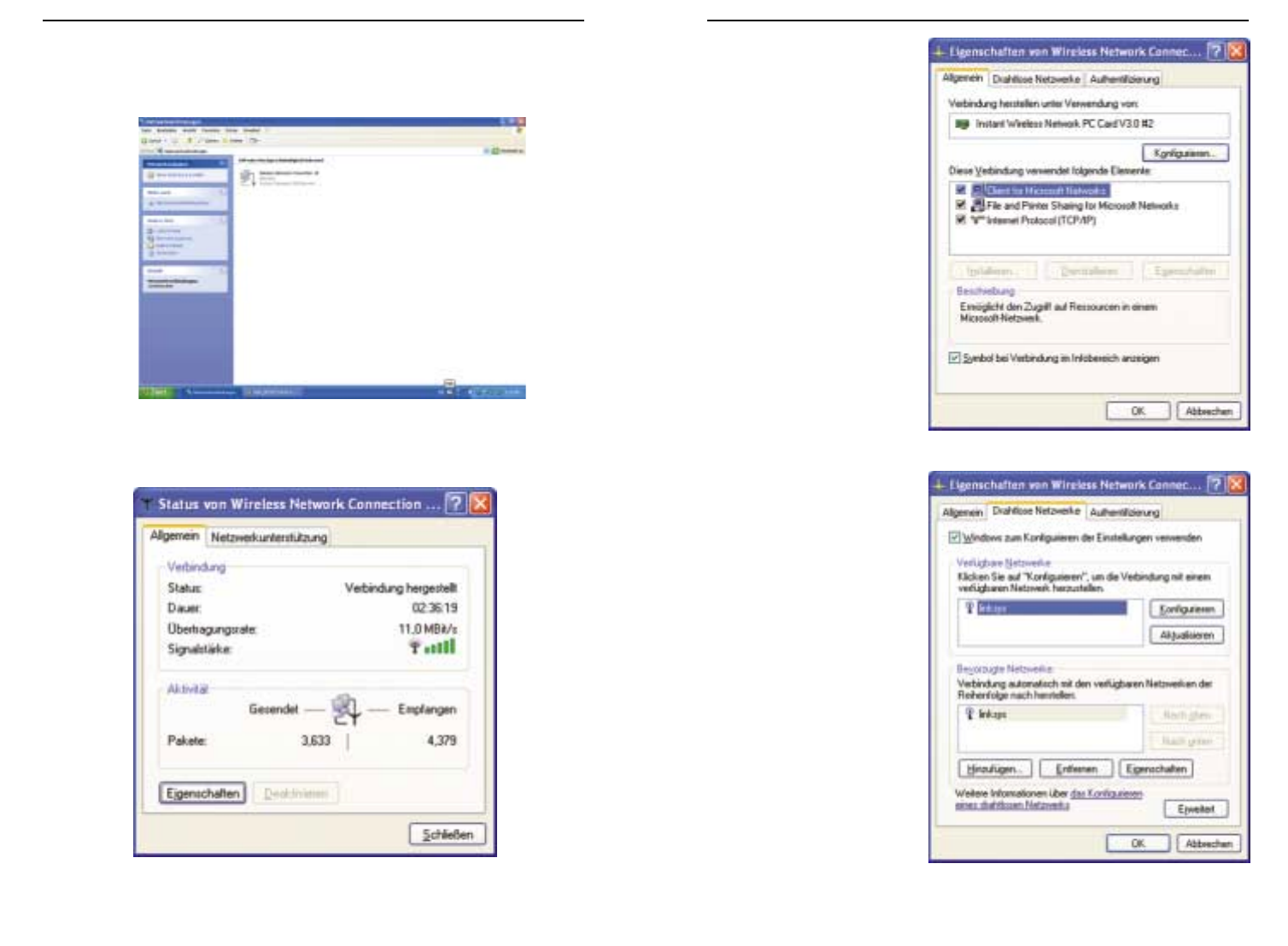
8382
Wireless Access Point-Router mit 4-Port-Switch
Instant Wireless™-Serie
6. Wird das Fenster
Eigenschaften von
Drahtloses Netzwerk
angezeigt (siehe
Abbildung C-8), klicken
Sie auf die Registerkarte
Drahtlose Netzwerke.
7. Wird im Abschnitt Bevor-
zugte Netzwerke das
entsprechende kabellose
Netzwerk über die SSID
des Routers angezeigt
(siehe Abbildung C-9),
doppelklicken Sie darauf
und fahren mit dem näch-
sten Schritt fort.
Andernfalls klicken Sie im
Abschnitt Verfügbare Netz-
werke auf das entspre-
chende, über die SSID des
Routers angezeigte
Netzwerk. Klicken Sie
anschließend auf die
Schaltfläche
Konfigurieren.
Abbildung C-8
Abbildung C-9
Wird das Fenster Mit dem drahtlosen Netzwerk verbinden angezeigt, klicken Sie
unter Verfügbare Netzwerke auf das gewünschte Netzwerk, das über die SSID des
Routers angegeben ist. Doppelklicken Sie dann auf das Symbol Drahtlose
Netzwerkverbindung.
5. Wird das Fenster Status von Drahtlose Netzwerkverbindung angezeigt (siehe
Abbildung C-7), klicken Sie auf die Schaltfläche Eigenschaften.
Abbildung C-6
Abbildung C-7
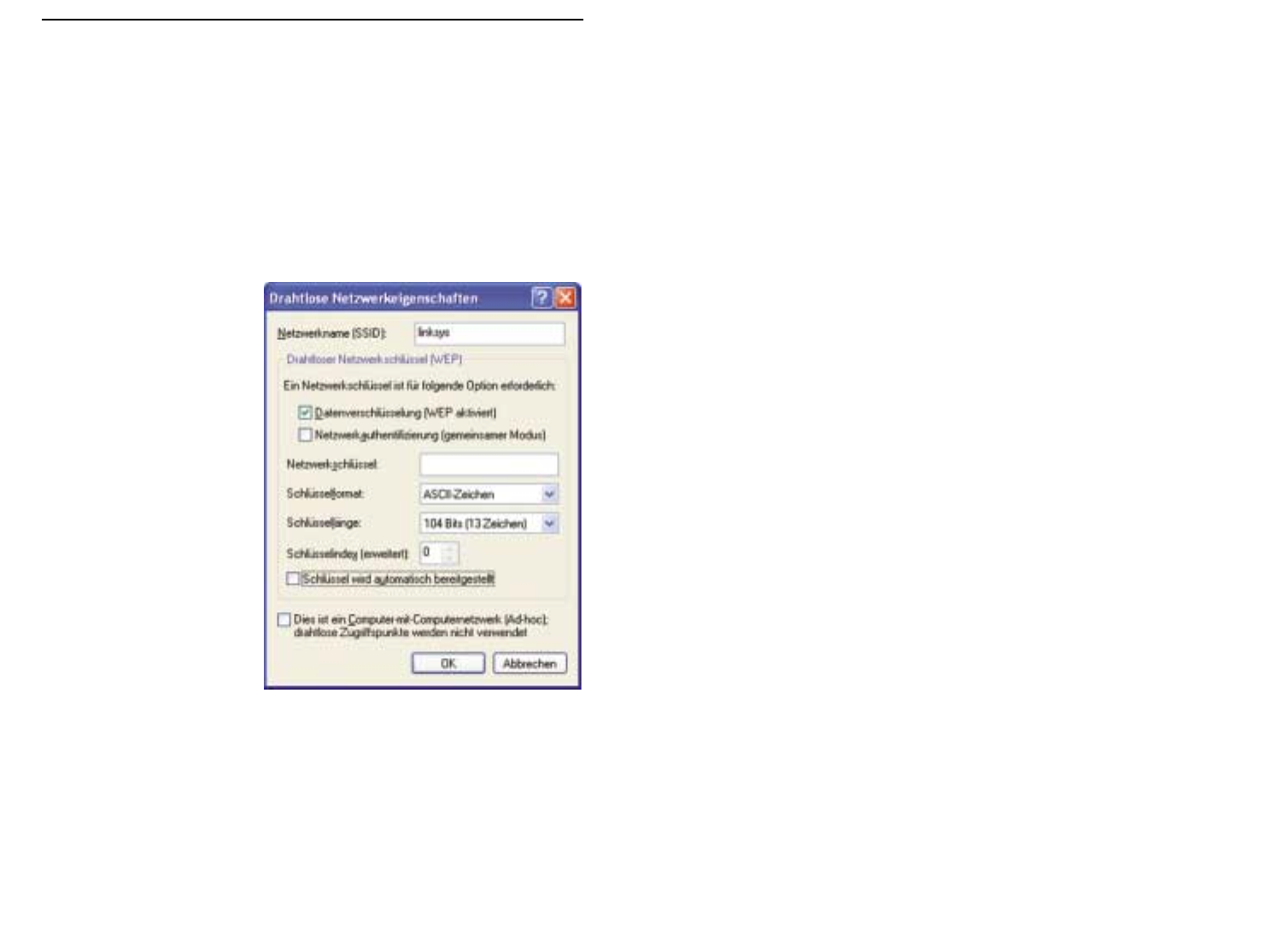
8584
Instant Wireless™-Serie
8. Das Fenster Eigenschaften von Drahtloses Netzwerk (siehe Abbildung C-10) wird
angezeigt.
Klicken Sie auf das Kontrollkästchen für die Option Datenverschlüsselung (WEP
aktiviert).
Deaktivieren Sie die Kontrollkästchen für die Optionen
Netzwerkauthentifizierung (gemeinsamer Modus) und Schlüssel wird automa-
tisch bereitgestellt.
Geben Sie im Feld Netzwerkschlüssel den exakten, vom Router generierten
Schlüssel ein (alle 10 bzw. 26 Ziffern, abhängig von der Verschlüsselungsstufe).
Vergewissern Sie sich, dass im
Feld Schlüsselformat die
Option Hexadezimalziffern
und im Feld Schlüssellänge
entweder die Option 40 Bits
(10 Ziffern) oder 104 Bits (26
Ziffern) angezeigt wird. Wird
keine diese Optionen
angezeigt, haben Sie den
Schlüssel falsch eingegeben.
Klicken Sie auf die Schaltfläche OK, um die Einstellungen zu speichern. Klicken
Sie auf die Schaltflächen OK, bis Sie wieder zum Fenster Status von Drahtlose
Netzwerkverbindung zurückgekehrt sind. Schließen Sie alle offenen Fenster, um
zum Desktop von Windows XP zurückzukehren.
Beenden Sie alle Anwendungen, und starten Sie Ihren PC neu. Nach dem Neustart ist
die WEP-Konfiguration abgeschlossen, und Sie sollten eine kabellose Verbindung zum
Router herstellen können.
Abbildung C-10

8786
COPYRIGHT E MARCHI REGISTRATI Copyright © 2002 Linksys. Tutti i diritti sono riser-
vati. Instant Wireless è un marchio della Linksys. Microsoft, Windows e il logotipo
Windows sono marchi registrati della Microsoft Corporation. Tutti gli altri marchi e nomi
commerciali sono di proprietà dei rispettivi titolari.
DICHIARAZIONE RELATIVA ALLA NORMATIVA FCC In base alle prove eseguite sull’ap-
parecchio Instant Wireless™ Wireless Access Point Router con switch a 4 porte si è deter-
minato che esso è conforme ai limiti relativi ai dispositivi digitali di classe B, secondo la
Parte 15 delle norme emanate dall’FCC (ente federale statunitense per le telecomuni-
cazioni). Tali norme sono state concepite per fornire una protezione adeguata da inter-
ferenze pericolose in ambienti residenziali. Questo apparecchio genera, utilizza e può
irradiare energia a radiofrequenza e, se non è installato e impiegato seguendo le
istruzioni, può causare interferenze dannose alle trasmissioni radio. Tuttavia non si può
garantire che non si verificheranno interferenze in installazioni specifiche. Se questo
apparecchio causasse interferenze dannose alle trasmissioni radio o televisive, con-
dizione determinabile spegnendo e accendendo l’apparecchio, si suggerisce all’utente
di cercare di eliminare le interferenze adottando una o più delle seguenti misure:
• orientare diversamente o spostare l’antenna ricevente;
• porre l’apparecchio ad una maggiore distanza dall’impianto ricevente;
• collegare l’apparecchio a una presa di corrente diversa da quello dell'impianto
ricevente;
• richiedere assistenza a un rivenditore o a un tecnico radiotelevisivo esperto.
Sommario
Introduzione 88
Passaggio 1: Collegamento del router 90
Passaggio 2: Configurazione dei PC 92
Passaggio 3: Configurazione del router 96
Guida 100
Configurazione della protezione Wireless 105
Configurazione della protezione Wireless in
Windows XP 108
Per assistenza, rivolgersi alla Linksys ai seguenti indirizzi:
E-mail europe-support@linksys.com
latam-soporte@linksys.com
Web http://www.linksys.com/international

8988
Le istruzioni fornite in questa Guida di avviamento rapido facilitano il collegamento al router,
la configurazione dei PC e la configurazione del router nella rete. Tali istruzioni dovrebbero
essere sufficienti per configurare e mettere in esecuzione una rete di base,condividendo l’ac-
cesso a Internet. Il router dispone inoltre di funzioni più avanzate il cui utilizzo però è con-
sigliato solo a chi ha familiarità con router e reti. Questi e altri problemi sono trattati nel
Manuale dell’utente sul CD-ROM di Setup Wizard (Installazione guidata).
L’impostazione
del router è
simile a quella
mostrata nella
figura prece-
dente per qualsiasi PC Windows. Il router consente di condividere la connessione cable o DSL
tra più computer a casa o in ufficio. Questo tipo di connessione è definito Local Area Network
(rete locale) o LAN.
Questa Guida di avviamento rapido fornisce un quadro generale di ciò che occorre per
impostare una rete di base in casa o in ufficio. Nelle tre sezioni successive viene spiegato
come impostare e configurare i propri apparecchi per consentire un accesso a Internet con-
diviso ad alta velocità.
Passaggio 1: Collegamento del router
L’utente viene assistito nel processo di collegamento del router al modem cable o DSL. Viene
quindi mostrato in che modo i PC sono collegati al router.
Passaggio 2: Configurazione dei PC
Viene descritto in che modo i PC sono configurati per comunicare con il router.
Passaggio 3: Configurazione del router
L’utente viene assistito in alcune impostazioni di base del router, che ne consentono il fun-
zionamento con il modem cable o DSL e le impostazioni del proprio ISP.
Wireless Access Point Router con switch a 4 porte
Serie Instant Wireless™
Grazie per aver scelto Instant Wireless™ Wireless Access Point Router. Questo router con-
sentirà di configurare una rete con i propri PC e di condividere il collegamento a Internet.
In che modo il router realizza tutto ciò? Collegando il modem cable o DSL direttamente al
router e utilizzando le porte Ethernet del router per collegare i PC,è come se ogni PC fosse
collegato direttamente a Internet. In questo modo,è possibile disporre di diversi PC in grado
di utilizzare simultaneamente un collegamento Internet. Inoltre, poiché è un Access Point,il
router può creare un ponte di collegamento tra la rete Ethernet e i PC Wireless.
Qual è il significato di tutto ciò quindi?
Le reti sono strumenti utili per la condivisione delle risorse del computer. È possibile
accedere a una stampante da computer differenti e accedere ai dati ubicati sull’unità disco
rigido di un altro computer. Le reti vengono inoltre utilizzate per i videogiochi in modalità
multiplayer. Non sono quindi destinate solamente ad un uso domestico e di ufficio, ma
hanno anche una funzione ludica.
I PC collegati alle quattro porte LAN del router, se configurati in modo appropriato, creano
una LAN o Local Area Network (rete locale). Vengono collegati con un cavo Ethernet inseri-
to nell’adattatore Ethernet del computer ad un’estremità e in una delle porte LAN del router
(con numero progressivo da uno a quattro) all’altra estremità. Il termine “Ethernet” viene
utilizzato per fare riferimento agli accessori di rete,come cavi e adattatori,poiché il termine
Ethernet fa riferimento al tipo di rete che si sta configurando. Nella documentazione relati-
va al router, il termine Ethernet fa riferimento agli accessori che trasferiscono i dati del
computer a una velocità compresa tra 10 Mbps e 100 Mbps. I termini 10 Mbps e 100 Mbps
fanno riferimento alla velocità utilizzata dai dispositivi di rete. Il trasferimento dei dati alla
velocità di 10 Mbps, è equivalente al trasferimento del contenuto di oltre sette floppy disk
al secondo. Gli accessori di rete che funzionano alla velocità di 100 Mbps trasferiscono i dati
a una velocità 10 volte superiore.
I PC possono inoltre interagire con il router in modalità Wireless. Configurando i PC in
modalità Wireless con le stesse impostazioni Wireless del router, è possibile creare un ponte
di collegamento tra i PC in modalità Wireless, integrandoli comunque nella rete Ethernet
esistente.
Tuttavia, la funzione più importante del router è che consente di condividere il collegamen-
to cable o DSL. Ciò viene effettuato collegando il modem cable o DSL alla porta WAN del
router con un cavo Ethernet. (WAN è l’acronimo di Wide Area Network). Internet è una rete
che, essendo globale, ricopre un’area vastissima. I PC collegati al router condividono tale
collegamento.
Introduzione
NNoottaa::questa Guida di avviamento rapido indicherà all’utente le modalità di configu-
razione del router con cavi Ethernet. Mentre il router può essere configurato attraverso
un collegamento Wireless, i dettagli relativi alla configurazione del router in modalità
Wireless non verranno approfonditi in questa Guida di avviamento rapido. Gli utenti che
desiderassero configurare il router attraverso il collegamento Wireless, dovrebbero fare
riferimento al sito Web di Linksys: www.linksys.com.
Quanto segue è ciò che si andrà a configurare

9190
Nel passaggio 1, si collegherà il router al modem cable o DSL e ai computer di casa o di
ufficio.
Innanzitutto,accertarsi che tutti gli apparecchi da utilizzare, inclusi i PC, il modem e il router,
siano scollegati dalla fonte di alimentazione.
A. Se non è già stato fatto, collegare correttamente il modem cable o DSL, ovvero utiliz-
zando il jack coassiale con il modem cable (Figura A1) o il jack telefonico con il modem
DSL (Figura A2). Seguire le istruzioni fornite nel manuale di installazione allegato al
modem cable o DSL.
Serie Instant Wireless™
B. Utilizzando un cavo Ethernet, collegare la
porta LAN o Ethernet del modem cable o
DSL alla porta WAN del router.
C. Collegare un cavo Ethernet all’a-
dattatore Ethernet del PC.
Collegare l’altra estremità del
cavo a una delle porte LAN del
router. Ripetere questo processo
per ogni PC che si desidera colle-
gare al router.
Nota: se l’adattatore Ethernet del PC non è configurato, fare riferimento alla documen-
tazione relativa all’adattatore Ethernet per ulteriori informazioni.
Per semplicità di installazione, iniziare con la
Porta LAN 1 sul router, proseguire con la
Porta 2, la Porta 3 e per finire con la Porta 4.
Se si stanno collegando più di quattro PC al
router, sarà necessario collegare un hub o
switch alla porta Uplink del router (se si uti-
lizza la porta Uplink, non è possibile utiliz-
zare la Porta 4). Per informazioni sul col-
legamento tramite porta Uplink, fare riferi-
mento al Manuale dell’utente contenuto nel
CD-ROM dell’Installazione guidata.
D. Collegare l’alimentatore di corrente alla
porta di alimentazione del router. Successivamente, collegare l’alimentatore a una
presa di corrente. Attivare il modem cable o DSL. Quindi accendere il primo PC che si
desidera utilizzare durante la configurazione del router.
Procedere al passaggio 2: Configurazione dei PC, alla pagina successiva.
Wireless Access Point Router con switch a 4 porte
A.1A.2
Passaggio 1: Collegamento del router
B
C1
C2

9392
Nel passaggio 2, verrà configurato ogni computer per la comunicazione con il router.
Per effettuare ciò, sarà necessario configurare le impostazioni di rete del PC in modo che
ottenga un indirizzo IP (o TCP/IP) automaticamente. I computer utilizzano gli indirizzi IP per
comunicare reciprocamente attraverso una rete o attraverso Internet.
Determinare il tipo di sistema operativo utilizzato dal computer: Windows 95, 98,
Millennium, 2000 o XP. È necessario conoscere il tipo di sistema operativo utilizzato dal
computer. È possibile determinarlo facendo clic sul pulsante Start/Avvio e successiva-
mente selezionando l’opzione Impostazioni. (Se il menu Start/Avvio non dispone del-
l’opzione Impostazioni,il sistema utilizzato è Windows XP. È possibile selezionare il Pannello
di controllo direttamente dal menu Start/Avvio). Successivamente, fare clic su Pannello di
controllo e fare doppio clic sull’icona Sistema. Fare clic sul pulsante Annulla al termine.
Una volta determinato il sistema operativo Windows utilizzato,seguire le istruzioni riportate
in questo passaggio relative al sistema operativo del proprio computer. È possibile sia ne-
cessario effettuare ciò per ogni computer da collegare al router.
Le pagine successive forniscono all’utente le indicazioni, passo dopo passo,per configurare
le impostazioni TCP/IP, sulla base del tipo di sistema operativo Windows utilizzato. Una volta
configurati i computer, proseguire con il passaggio 3:Configurazione del router
A. Fare clic sul pulsante Start/Avvio, quindi su
Impostazioni e aprire il Pannello di control-
lo. Da tale posizione, fare doppio clic sull’icona
Rete per aprire la schermata relativa alla rete.
B. Selezionare la scheda Configurazione e evi-
denziare la voce TCP/IP relativa all’adattatore
Ethernet* utilizzabile. Se il termine TCP/IP
viene visualizzato da solo, selezionarlo**.
Successivamente, fare clic sul pulsante
Proprietà.
C. Fare clic sulla scheda Indirizzo IP e
selezionare Ottieni automaticamente un ind-
irizzo IP.
D. Fare clic sulla scheda Gateway e verificare che
il campo Gateway installati sia vuoto. Fare clic
sul pulsante OK.
E. Fare nuovamente clic sul pulsante OK.
Windows potrebbe richiedere il disco originale
di installazione di Windows o file aggiuntivi.
Fornire tali file, indicando l’ubicazione corretta
degli stessi: ad esempio, D:\win98, D:\win9x,
c:\windows\options\cabs ,ecc. (Ciò presuppone che “D”corrisponda alla lettera dell’u-
nità CD-ROM).
F. Se Windows richiede di riavviare il PC, fare clic sul pulsante Sì. Se Windows non
richiede il riavvio, riavviare comunque il computer.
*Nota: non selezionare una voce TCP/IP il cui nome contenga DUN,PPPoE,VPN o AOL.
**Nota: se non è elencata una linea TCP/IP, fare riferimento al Manuale dell’utente con-
tenuto nel CD-ROM dell’Installazione guidata o nella documentazione relativa all’adat-
tatore Ethernet per installare ora il protocollo TCP/IP.
Serie Instant Wireless™ Wireless Access Point Router con switch a 4 porte
Passaggio 2: Configurazione dei PC Se si utilizza:
Windows 95, Windows 98, Windows Me
B
C
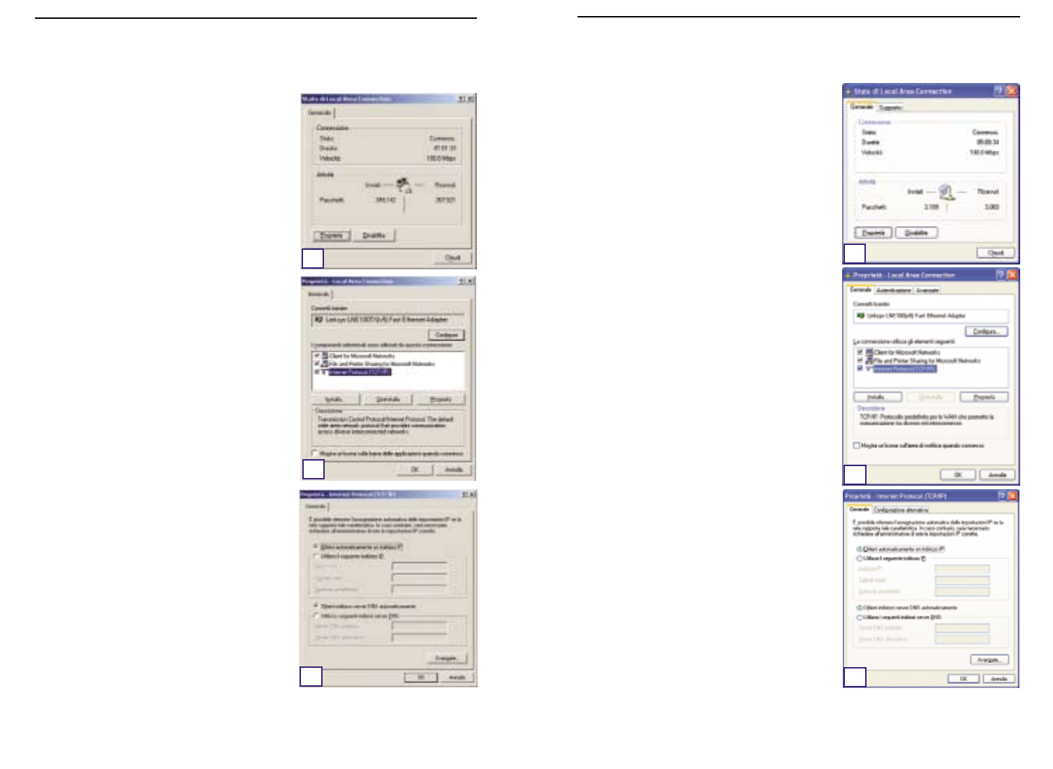
9594
Le istruzioni seguenti presuppongono l’utilizzo del-
l’interfaccia predefinita di Windows XP. Se si utilizza
l’interfaccia Classica (in cui le icone e i menu hanno
lo stesso aspetto delle precedenti versioni di
Window), seguire le istruzioni relative a Windows
2000.
A. Fare clic sul pulsante Start,aprire il Pannello di
controllo e fare clic sull’icona Rete e connes-
sioni Internet. Successivamente, fare clic sul-
l’icona Connessioni di rete per visualizzare la
schermata relativa alla Rete.
B. Selezionare l’icona Connessione alla rete
locale (LAN) per l’adattatore Ethernet* utilizz-
abile (solitamente è la prima Connessione alla
rete locale elencata). Fare doppio clic su
Connessione alla rete locale (LAN).
C. Quando viene visualizzata la schermata Stato di
Connessione alla rete locale (LAN), fare clic sul
pulsante Proprietà.
D. Selezionare Protocollo Internet (TCP/IP) e fare
clic sul pulsante Proprietà.
E. Selezionare Ottieni automaticamente un indi-
rizzo IP e fare clic sul pulsante OK sulle scher-
mate successive per completare la configu-
razione del PC.
F. Riavviare il computer.
A. Fare clic sul pulsante Start/Avvio, quindi su
Impostazioni e aprire il Pannello di controllo.
Da tale posizione, fare doppio clic sull’icona Rete
e connessioni remote. In questo modo verrà
visualizzata la schermata relativa alla Rete.
B. Selezionare l’icona Connessione alla rete
locale (LAN) per l’adattatore Ethernet* utilizz-
abile (solitamente è la prima Connessione alla
rete locale elencata). Fare doppio clic su
Connessione alla rete locale (LAN).
C. Quando viene visualizzata la schermata Stato di
Connessione alla rete locale (LAN), fare clic sul
pulsante Proprietà.
D. Selezionare Protocollo Internet (TCP/IP) e fare
clic sul pulsante Proprietà.
E. Selezionare Ottieni automaticamente un indi-
rizzo IP e fare clic sul pulsante OK sulle scher-
mate successive per completare la configu-
razione del PC.
F. Riavviare il computer.
*Nota: non selezionare una voce TCP/IP il cui nome
contenga DUN,PPPoE,VPN o AOL.
Serie Instant Wireless™ Wireless Access Point Router con switch a 4 porte
Se si utilizza:
Windows 2000
E
D
C
Se si utilizza:
Windows XP
C
D
E
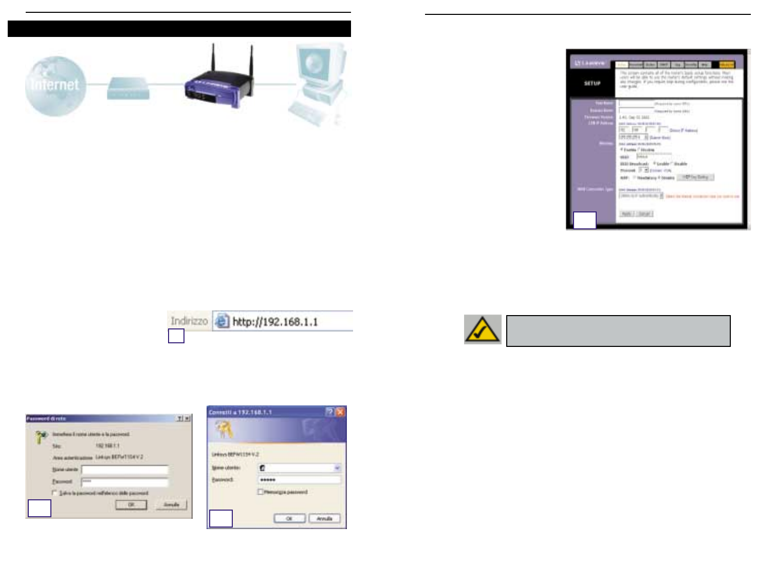
9796
C.
Se richiesto dall’ISP, immettere l’Host Name (Nome host) e il Domain Name (Nome
dominio) del router nei campi appropriati della scheda Setup (Configurazione). (Ciò viene
richiesto solitamente dagli ISP che
offrono una connessione cable).
D. Per configurare il router per la
rete Wireless, verificare che i
campi Wireless della scheda
Setup (Configurazione) (mostrati
nella figura D) vengano comple-
tati nel modo seguente:
Enable/Disable
(Abilita/Disabilita): La selezione
del pulsante di opzione Enable
(Abilita), consentirà l’abilitazione
della funzionalità Wireless del
router. Le funzionalità Wireless
non saranno disponibili se non
abilitate.
SSID: SSID (o ESSID) è un nome univoco per la rete Wireless. Fa distinzione tra il
maiuscolo e il minuscolo e non deve superare i 32 caratteri. L’SSID predefinito è
“linksys “ ma è necessario modificarlo con un nome di rete Wireless personale. Tutte
le postazioni della rete Wireless devono utilizzare lo stesso SSID.
Channel (Canale): Selezionare il canale appropriato alla propria rete dall’elenco forni-
to. Tutte le postazioni Wireless della rete devono utilizzare lo stesso canale per fun-
zionare in maniera appropriata.
E. Il router supporta cinque tipi di connessione: DHCP (ottiene un indirizzo IP automatica-
mente), PPPoE, Static IP Address (Indirizzo IP statico) , RAS e PPTP. Questi tipi vengono
selezionati dal menu a discesa accanto a WAN Connection Type (Tipo di connessione
WAN). La schermata Setup (Configurazione) e le funzionalità disponibili differiranno in
relazione al tipo di connessione selezionata, le cui istruzioni sono incluse nel presente
manuale:
1. Obtain an IP Automatically (Ottieni un indirizzo IP automaticamente)
Se l’ISP determina che il collegamento avviene tramite un indirizzo IP dinamico (o DHCP),
seguire i passaggi di seguito riportati:
a. Selezionare Obtain an IP automatically (Ottieni un indirizzo IP automaticamente)
come tipo di connessione WAN (secondo quanto mostrato in precedenza nella figura
D).
b. Fare clic sul pulsante Apply (Applica) per salvare le impostazioni.
Nel passaggio 3, verrà configurato il router per il funzionamento nella propria rete e per
ottenere l’accesso a Internet tramite il proprio ISP (Internet Service Provider). L’ISP potrebbe
richiedere l’utilizzo di un Nome host e di un Nome dominio. Inoltre,verrà configurato il tipo
di configurazione WAN (WAN Configuration Type) sulla scheda Setup (Configurazione) del
router sulla base delle informazioni fornite dall’ISP.
Tali informazioni di configurazione sono
messe a disposizione dall’ISP.
Se non si è in possesso di tali informazioni, contattare il pro-
prio ISP prima di continuare. Per determinare le informazioni da richiedere all’ISP, fare riferi-
mento alla domanda n°1 contenuta nella sezione Guida.
Le istruzioni fornite dall’ISP indicano le modalità di configurazione del PC per l’accesso a
Internet. Poiché ora si sta utilizzando il router per la condivisione dell’accesso a Internet
tra diversi computer, tali informazioni di configurazione verranno impiegate per la configu-
razione router.
A. Aprire il browser Web. (È normale che venga visualizzato un messaggio di errore a
questo punto. Continuare a seguire queste istruzioni). Immettere 192.168.1.1 nel
campo Indirizzo del browser Web
e premere il tasto Invio.
B. Viene visualizzata la finestra Enter
Network Password (Password di
rete), mostrata nella figura A1. (Agli utenti di Windows XP verrà visualizzata la finestra
Connect to 192.168.1.1 (Connetti a 192.168.1.1), mostrata nella figura A2.). Lasciare il
campo User Name (Nome utente) vuoto e immettere admin (la password predefinita) in
caratteri minuscoli nel campo Password. Successivamente, fare clic sul pulsante OK.
Serie Instant Wireless™ Wireless Access Point Router con switch a 4 porte
Passaggio 3: Configurazione del router
A
A.1A.2
D
NNoottaa:: se si desidera modificare le impostazioni WEP del
router, passare alla sezione Configurazione della protezione
Wireless.
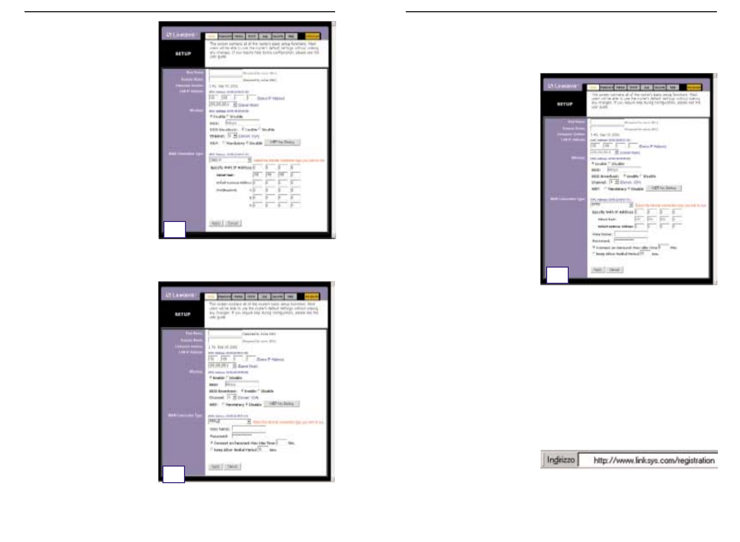
9998
Wireless Access Point Router con switch a 4 porte
4. RAS
RAS è un servizio utilizzato solo a Singapore. Se si utilizza una connessione RAS, verificare
con il proprio ISP le informazioni di configurazione necessarie.
5. PPTP
PPTP è un servizio utilizzato solo in
Europa. Se si utilizza una connessione
PPTP, verificare con il proprio ISP le
informazioni di configurazione neces-
sarie.
F. Se non è ancora stato fatto, fare clic sul pulsante Apply (Applica) per salvare le
impostazioni.
G. Fornire di nuovo l’alimentazione al modem cable o DSL e riavviare i computer. Le nuove
impostazioni del router diventeranno effettive.
Nota:è necessario configurare il router solo da un computer. Se occorrono informazioni
sulle impostazioni avanzate, visitare il sito Web dell’assistenza di Linksys all’indirizzo
support.linksys.com
o consultare il Manuale dell’utente nel CD-ROM di Setup Wizard
(Installazione guidata).
Congratulazioni. Il router è stato correttamente configurato. È possibile verificarne la
configurazione aprendo una sessione del browser Web da un qualsiasi computer e
immettendo
www.linksys.com/registration
.
Se non si riesce a raggiungere il sito Web di Linksys, potrebbe essere necessario
rivedere le impostazioni effettuate in questa sezione oppure consultare la sezione Guida
in questa Guida di avviamento rapido.
Serie Instant Wireless™
2. Static IP (IP statico)
Se l’ISP determina che il collegamento
avviene tramite un indirizzo IP statico
(o fisso), seguire i passaggi riportati di
seguito.
a. Selezionare Static IP (IP statico)
come tipo di connessione WAN.
b. Nei campi accanto a “Specify WAN
IP Address” (Specificare indirizzo
IP WAN) immettere l’indirizzo IP.
c. Immettere la Subnet Mask.
d. Immettere il Default Gateway
Address (Indirizzo gateway
predefinito).
e. Immettere il DNS nei campi 1, 2
e/o 3. È necessario immettere
almeno un indirizzo DNS.
f. Fare clic sul pulsante Apply (Applica) per salvare le impostazioni.
3. PPPoE
Se il provider DSL determina che il
collegamento avviene tramite una
connessione PPPoE o se di solito si
immette un nome utente e una pass-
word per accedere a Internet, seguire
i passaggi riportati di seguito.
a. Selezionare PPPoE come tipo di
connessione WAN.
b. Immettere lo User Name (Nome
utente).
c. Immettere la Password.
d. Fare clic sul pulsante Apply
(Applica) per salvare le
impostazioni.
e. Fare clic sulla scheda Status
(Stato) seguita dal pulsante Connect (Collegare) per avviare la connessione.
E2
E3
E5

101100
Wireless Access Point Router con switch a 4 porte
2. Si stanno verificando dei problemi di connessione a Internet. Quali LED dovreb-
bero essere accesi sul pannello anteriore del router?
•Si accenderà un LED del router per ogni collegamento correttamente effettuato sulla
parte posteriore del router, sia che si tratti di un cavo Ethernet o di un cavo di ali-
mentazione.
Di seguito sono riportati i tipici LED che si accendono dopo aver collegato un computer
e un modem cable o DSL:
- Quando il router è acceso (l’adattatore di alimentazione è inserito nel
router), il LED
Power (Alimentazione)
è acceso.
- Quando un cavo Ethernet è correttamente collegato tra un PC e la porta 4 del
router, i LED
Link/Act
,
Ful/Col
e
100
nella colonna 4 sono accesi.
- Con una connessione modem cable o DSL il LED
WAN Link
è acceso.
Serie Instant Wireless™
Nella sezione Guida sono contenute le domande più frequenti relative alla connessione a
Internet. In caso occorrano ulteriori informazioni sull’installazione o sulle funzioni avanzate,
andare all’indirizzo
kb.linksys.com
o consultare il Manuale dell’utente contenente un’ap-
pendice Risoluzione dei problemi, disponibile nel CD-ROM di Setup Wizard (Installazione
guidata).
1. In caso di dubbio sulle informazioni da richiedere all’Internet Service Provider
(ISP) per configurare e mettere in funzione la rete, quali domande si dovrebbero
fare?
Di che tipo di connessione dispongo: indirizzo IP dinamico, indirizzo IP statico o PPPoE?
•Se utilizzo un indirizzo IP dinamico,dovrei chiedere:
- Qual è il mio nome host (se necessario)?
- Qual è il mio nome dominio (se necessario)?
•Se utilizzo un indirizzo IP statico,dovrei chiedere:
- Qual è il mio indirizzo IP?
- Qual è il mio gateway?
- Qual è il mio DNS?
•Se utilizzo PPPoE (in genere utilizzato dagli ISP che offrono una connessione DSL),
dovrei chiedere:
- Qual è il mio nome utente?
- Qual è la mia password?
Una volta ottenute le informazioni, seguire le istruzioni nella Guida di avviamento rapido al
passaggio 3:Configurazione del router e immettere queste informazioni nella scheda Setup
(Configurazione). Nella sezione WAN Connection Type (Tipo di connessione WAN) fare riferi-
mento al grafico sulla pagina successiva:
Guida ?Dynamic IP Address
(DHCP) (Indirizzo IP
dinamico)
1. Selezionare Obtain an IP automatically (Ottieni un indiriz-
zo IP automaticamente) come tipo di connessione WAN.
2. Fare clic sul pulsante Apply (Applica) per salvare le
impostazioni.
Seguire i passaggi riportati di seguito:
PPPoE 1. Selezionare Static IP (IP statico) come tipo di connessione
WAN.
2. Immettere lo User Name (Nome utente).
3. Immettere la Password.
4. Fare clic sul pulsante Apply (Applica) per salvare le
impostazioni.
Static IP Address
(Indirizzo IP statico) 1. Selezionare Static IP (IP statico) come tipo di connessione
WAN.
2. Immettere l’IP Address (Indirizzo IP).
3. Immettere la Subnet Mask.
4. Immettere il Gateway Address (Indirizzo gateway).
5. Immettere il DNS nei campi 1, 2 e/o 3. È necessario immet-
tere almeno un indirizzo DNS.
6. Fare clic sul pulsante Apply (Applica) per salvare le
impostazioni.
RAS o PPTP Se si utilizza RAS (Singapore SingTel) o PPTP (servizio europeo),
verificare presso il proprio ISP le informazioni di configurazione
necessarie.
Se si dispone di questo
tipo di connessione:

103102
Wireless Access Point Router con switch a 4 porte
•Nel campo Indirizzo IP sarà visualizzato un indirizzo IP, come 192.168.1.100 o
192.168.1.xxx, dove “xxx” è un numero maggiore di 100. Se l’indirizzo IP visualizzato
non rientra in questo intervallo,tenere premuto il pulsante Reset (Ripristina) sulla parte
anteriore del router per più di 30 secondi. Verranno così ripristinate le impostazioni pre-
definite del router e sarà necessario riconfigurarlo attraverso la pagina Setup
(Impostazione). Al termine, riavviare il computer.
C. Configurare ora alcune impostazioni in Windows.
- Sul desktop fare doppio clic su Risorse del computer, quindi fare doppio clic su
Pannello di controllo (per gli utenti di Windows XP che utilizzano l’interfaccia pre-
definita, fare clic sul pulsante Start e scegliere Pannello di controllo).
- Nella finestra del Pannello di controllo fare doppio clic sull’icona Opzioni Internet (per
gli utenti di Windows XP che utilizzano l’interfaccia predefinita,fare clic su Rete e con-
nessioni Internet, quindi scegliere Opzioni Internet).
- Nella finestra Opzioni Internet fare clic sulla scheda Connessioni.
- Selezionare Non utilizzare mai connessioni remote (questa opzione potrebbe anche
essere inattiva).
- Fare clic sul pulsante Impostazioni LAN nell’angolo inferiore destro.
- Nella finestra Impostazioni rete locale (LAN) deselezionare tutte le caselle.
- Fare clic sul pulsante OK,quindi su Applica (se non è stata apportata alcuna modifica,
il pulsante Applica è inattivo). Successivamente, fare di nuovo clic sul pulsante OK.
- Uscire dal Pannello di controllo e riavviare il computer.
4. È impossibile eseguire la connessione a Internet anche dopo aver fatto clic sul-
l’icona per accedere a Internet e aver immesso il nome utente e la password for-
niti dall’ISP. Qual è il problema?
Il problema deriva dal fatto che si sta utilizzando il software fornito dall’ISP. Utilizzare invece
il browser Internet Explorer o Netscape Navigator situati sul desktop (nel menu di avvio in
Windows XP).
5. Durante l’utilizzo di Internet Explorer, viene visualizzata una finestra popup in
cui viene richiesto di effettuare una connessione remota. Come è possibile dis-
attivarla?
A. Sul desktop fare doppio clic su Risorse del computer, quindi fare doppio clic su
Pannello di controllo (per gli utenti di Windows XP che utilizzano l’interfaccia pre-
definita, fare clic sul pulsante Start e scegliere Pannello di controllo).
B. Nella finestra del Pannello di controllo fare doppio clic sull’icona Opzioni Internet (per
gli utenti di Windows XP che utilizzano l’interfaccia predefinita,fare clic su Rete e con-
nessioni Internet, quindi scegliere Opzioni Internet).
C. Nella finestra Opzioni Internet fare clic sulla scheda Connessioni.
Serie Instant Wireless™
•Il LED
WAN Link (collegamento WAN)
non è acceso. Quali verifiche occorre fare?
- Verificare che il cavo utilizzato per collegare il modem cable o DSL al router sia
quello fornito in dotazione con il modem. A seconda del tipo di connessione uti-
lizzato dal modem, potrebbe essere necessario un cavo Ethernet “semplice”
o “incrociato” (il tipo “semplice” è quello più comune).
•Alcune delle spie luminose sulla parte anteriore del router non si accendono quando si
collega un PC.
- Affinché una connessione funzioni correttamente è sufficiente che sia acceso il
LED
Link/Act
.
3. È impossibile accedere a Internet o visualizzare la pagina per l’impostazione del
router. Quali verifiche occorre fare?
A. Innanzitutto controllare che il modem cable o DSL e i computer siano correttamente
collegati al router. Per informazioni su come verificare che le connessioni funzionino
correttamente, tornare alla domanda n. 2.
B. Verificare quindi di aver configurato correttamente il PC per la comunicazione con il
router. Di seguito sono riportate le istruzioni per diverse versioni di Windows.
-Windows 95, 98 o ME
•Fare clic sul pulsante Start (Avvio) e scegliere Esegui. Nella finestra di dialogo
Esegui immettere winipcfg nel campo Apri, quindi fare clic sul pulsante OK.
•Nella finestra Configurazione IP fare clic sulla casella grigia con una
freccia nera rivolta verso il basso.
•Verrà visualizzato un elenco di adattatori. Selezionare l’adattatore da utilizzare
per connettersi a Internet. Le voci dell’elenco non devono contenere nel nome
“PPP”,“VPN”,“AOL” o “Dial-Up adapter”.
•Nel campo Indirizzo IP sarà visualizzato un indirizzo IP, come 192.168.1.100 o
192.168.1.xxx, dove “xxx” è un numero maggiore di 100. Se l’indirizzo IP visual-
izzato non rientra in questo intervallo, tenere premuto il pulsante Reset
(Ripristina) sulla parte anteriore del router per oltre 30 secondi. Verranno così
ripristinate le impostazioni predefinite del router e sarà necessario riconfigurar-
lo attraverso la pagina Setup (Impostazione). Al termine,riavviare il computer.
-Windows NT, 2000 e XP
•Fare clic sul pulsante Start (Avvio) e scegliere Esegui. Nella finestra di dialogo
Esegui immettere cmd nel campo Apri, quindi fare clic sul pulsante OK.
•Verrà visualizzato un prompt dei comandi. Immettere ipconfig /all, quindi pre-
mere il tasto Invio.
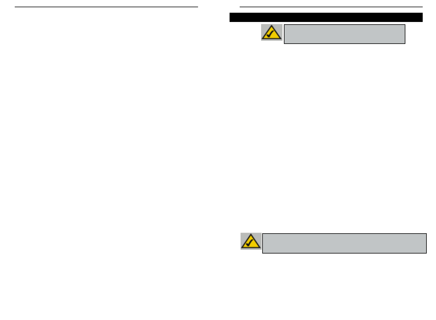
105104
Wireless Access Point Router con switch a 4 porte
Serie Instant Wireless™
D. Selezionare Non utilizzare mai connessioni remote.
E. Fare clic sul pulsante Applica.
F. Fare clic sul pulsante OK.
6. Cosa fare se non si riceve l’intensità del segnale o la qualità del collegamento?
A. Verificare che il LED WLAN del router sia acceso.
B. Verificare che tutti i PC wireless stiano utilizzando la modalità “Infrastructure”
(Infrastruttura).
7. In che modo è possibile incrementare il raggio di azione del router?
A. Verificare che il router si trovi il più in alto possibile da terra.
B. Verificare che nelle vicinanze non vi siano grandi sorgenti di interferenze elettriche (ad
esempio,altoparlanti, luci fluorescenti,forni a microonde e così via).
C. Cambiare il canale wireless in uso nel modo seguente:
- Aprire una sessione del browser e digitare http://192.168.1.1 nel campo “Indirizzo”.
- Nella finestra “Password di rete” lasciare vuoto il campo “Nome utente” e digitare
admin come password. Quindi fare clic su OK.
- Nella scheda Setup (Configurazione) impostare il canale su 1.
- Fare clic sul pulsante Apply (Applica) per salvare le impostazioni.
- Ripetere l’operazione fino a trovare il canale che fornisce il migliore raggio di azione.
WEP, un acronimo di Wired Equivalent Privacy, è un metodo di crittografia utilizzato
per proteggere le comunicazioni dei dati in modalità Wireless. WEP utilizza una com-
binazione di chiavi a 64 bit o 128 bit per fornire il controllo di accesso alla rete e per
fornire la protezione di tipo crittografico ad ogni trasmissione di dati. Per decodificare
una trasmissione di dati, ogni postazione della rete deve utilizzare una chiave a 64 bit o
a 128 bit identica. Livelli superiori di crittografia comportano livelli più elevati di pro-
tezione, tuttavia, a causa della complessità della crittografia, potrebbero comportare un
minore rendimento della rete.
Quando si parla di crittografia WEP, ricorre a volte il termine “40 bit” . Si tratta sem-
plicemente di un altro termine che sta ad indicare la codifica WEP a 64 bit. Questo li-
vello di crittografia WEP è stato denominato a 40 bit poiché si serve di una chiave se-
greta a 40 bit unitamente a un vettore di inizializzazione a 24 bit (40 + 24 = 64). È pos-
sibile che i fornitori di accessori Wireless utilizzino una denominazione differente.
Linksys utilizza il termine “64 bit” quando fa riferimento a questo livello di crittografia.
Accertarsi che la rete Wireless sia funzionante prima di tentare la configurazione della
crittografia WEP.
Una rete Wireless con crittografia WEP a 128 bit NON comunicherà con una rete
Wireless con crittografia WEP a 64 bit. Pertanto, accertarsi che tutti i dispositivi
Wireless stiano utilizzando lo stesso livello di crittografia. Tutti i dispositivi Wireless
conformi allo standard 802.11b supporteranno la crittografia WEP a 64 bit.
Oltre ad abilitare la crittografia WEP, Linksys raccomanda inoltre le implementazioni di
protezione seguenti:
•Modificare l’SSID predefinito “linksys”
•Modificare la chiave WEP regolarmente
Nota: la crittografia WEP è una misura di protezione dati
aggiuntiva e non essenziale per il funzionamento del
router.
Nota: per poter abilitare la Crittografia WEP, è necessario prima abilitare le
funzionalità Wireless. Selezionare Enable (Abilita) sulla scheda Wireless del
router prima di continuare.
Configurazione della protezione Wireless
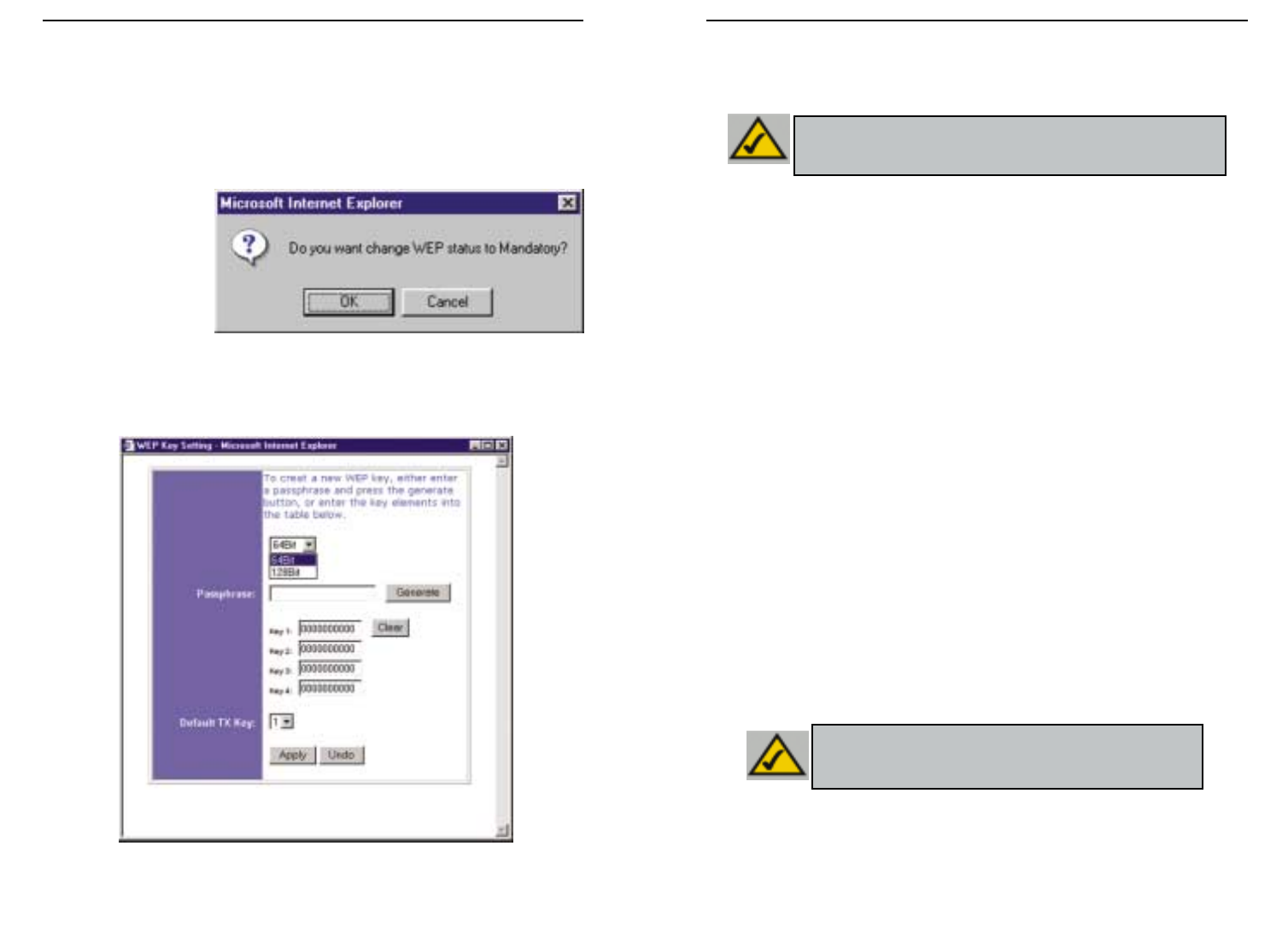
107106
Wireless Access Point Router con switch a 4 porte
Serie Instant Wireless™
• WEP (64 Bit o 128 Bit) Selezionare il livello di crittografia dalla casella a discesa.
La crittografia WEP a 128 bit è univoca per Linksys e potrebbe andare in conflitto
con altre forme di crittografia WEP di altri fornitori.
La chiave di crittografia WEP viene generata in uno dei seguenti modi:
1. È possibile creare una chiave di crittografia utilizzando una Passphrase.
a. Immettere una Passphrase, una password definita dall’utente, nel campo
Passphrase. La Passphrase può contenere un massimo di 31 lettere, simboli e
numeri. Non è possibile utilizzare spazi.
b. Fare clic sul pulsante Generate (Genera) per creare una chiave. La chiave sarà
costituita da 10 cifre se è stata scelta una crittografia a 64 -bit o da 26 cifre se è
stata scelta una crittografia a 128 bit. Questa chiave verrà utilizzata per codifi-
care e decodificare i dati scambiati tra il router e i PC Wireless della rete.
È possibile che il campo Key (Chiave) non visualizzi tutte le cifre. Con il mouse,
fare clic in qualsiasi punto del campo Key (Chiave). Spostare il cursore sulla
destra per visualizzare il resto della chiave. Accertarsi di aver annotato l’intera
chiave ESATTAMENTE nel modo in cui viene visualizzata.
2. È possibile immettere la chiave di crittografia manualmente.
Prendere nota della Passphrase o della chiave manuale (Manual Key). Sarà necessaria
per gli altri dispositivi Wireless presenti nella rete, poiché è necessario immettere la
stessa chiave di crittografia WEP per tutti i dispositivi Wireless presenti nella rete.
Una volta scelto il metodo di crittografia a chiavi e una volta immessa la Passphrase o
la chiave manuale, fare clic sul pulsante Apply (Applica) e la parte relativa alla crit-
tografia della configurazione è completata.
Nota: per poter utilizzare la crittografia WEP, tutte le postazioni nella
rete Wireless devono avere il protocollo WEP abilitato e configurato
con la stessa configurazione della chiave.
Nota: in Windows XP, una chiave a 128 bit generata dal router,
verrà denominata chiave a “104 bit (26 cifre)” e una chiave a
64 bit verrà denominata chiave a “40 bit (10 cifre)”.
I passaggi seguenti mostrano come utilizzare la crittografia WEP
1. Dalla scheda Utility’s setup (Configurazione dell’Utilità) basata su Web, selezionare
Mandatory (Obbligatorio) sotto la sezione WEP.
2. Premere il pulsante WEP Key Setting (Impostazione chiave WEP) per configu-
rare il tipo e il livello di Crittografia WEP.
3. È possibile che
venga visualizzata la
schermata riportata
nella figura C-1, che
richiede la conferma
dell’abilitazione
della crittografia
WEP. Premere il
pulsante OK per
continuare.
4. Ciò porterà alla visualizzazione della schermata riportata nella figura C-2. Da tale
schermata, verranno scelte le impostazioni di crittografia WEP.
Figura C-2
Figura C-1
109108
Wireless Access Point Router con switch a 4 porte
Serie Instant Wireless™
2. Nella finestra “Pannello di controllo”, fare clic sull’icona Rete e connessioni
Internet, riportata nella figura C-4.
3. Fare clic sull’icona Connessioni di rete, riportata nella figura C-5.
4. Verrà visualizzata la finestra “Connessioni di rete” , come riportato nella figura C-
6. Sotto la voce LAN o Internet ad alta velocità, verranno visualizzate tutte le
schede di rete installate e funzionanti del computer. Fare doppio clic sull’icona
Connessione di rete Wireless associata all’adattatore Wireless.
Se viene visualizzata la finestra “Stato di Connessione alla rete Wireless”, pro-
seguire al passaggio successivo.
Figura C-4
Figura C-5
Poiché Windows XP non consente di utilizzare la funzionalità Passphrase di Linksys
con gli adattatori Wireless del PC , sarà necessario immettere manualmente la chiave
generata nella sezione precedente.
I passaggi seguenti consentiranno di abilitare il WEP e di immettere la chiave di crit-
tografia per le schede Wireless dei PC, al fine di consentire al sistema Windows XP di
comunicare con il router in modalità Wireless.
Questi passaggi presuppongono che all’unità CD-ROM sia assegnata la lettera D e che
si stia utilizzando Windows XP nella modalità predefinita.
Accertarsi di disporre della chiave WEP generata dal router.
1. Secondo quanto visualizzato nella figura C-3, fare clic sul pulsante Start e portar-
si sul Pannello di controllo.
Figura C-3
Configurazione della protezione Wireless in Windows XP
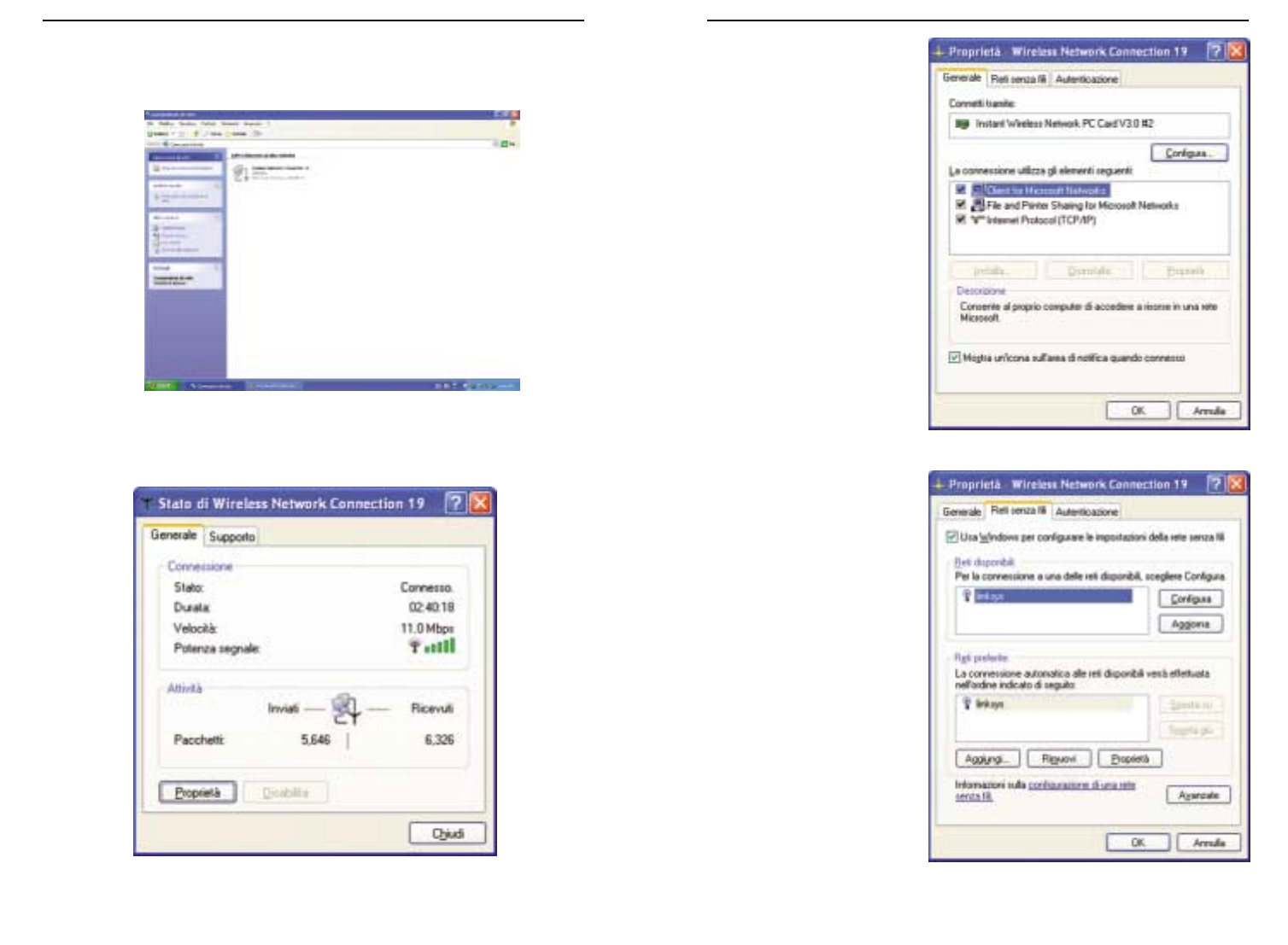
111110
Wireless Access Point Router con switch a 4 porte
Serie Instant Wireless™
6. Quando viene visualizzata
la finestra “Proprietà -
Connessione alla rete
Wireless”, secondo quanto
riportato nella figura C-8,
fare clic sulla scheda Reti
Wireless.
7.
Se la rete Wireless appro-
priata, specificata dall’SSID
del router, viene visualizzata
nella sezione “Reti pre-
ferite”, come riportato nella
figura C-9, fare doppio clic
su di essa e proseguire al
passaggio successivo.
Altrimenti, fare clic sulla
rete Wireless appropriata,
specificata dall’SSID del
router, nella sezione “Reti
disponibili”. Successi-
vamente, fare clic sul pul-
sante Configura.
Figura C-8
Figura C-9
Se viene visualizzata la finestra “Connessione alla rete Wireless”, nella sezione Reti
disponibili, fare clic sulla rete Wireless desiderata, specificata dall’SSID del router.
Successivamente, fare doppio clic sull’icona Connessione alla rete Wireless.
5. Quando viene visualizzata la finestra “Stato di connessione alla rete Wireless”,
come riportato nella figura C-7, fare clic sul pulsante Proprietà.
Figura C-6
Figura C-7
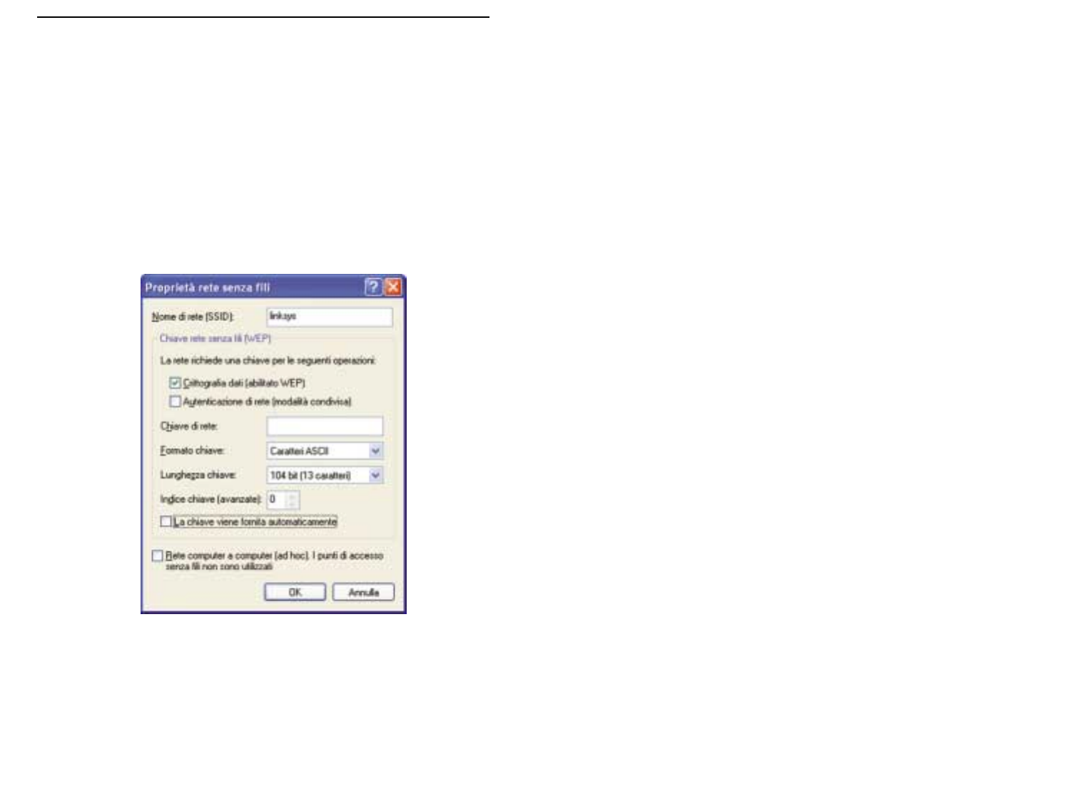
113112
Serie Instant Wireless™
8.
Verrà visualizzata la finestra “Proprietà - Rete Wireless” (riportata nella figura C-10).
Fare clic sulla casella di controllo relativa all’opzione Crittografia dati (WEP abilita-
to).
Deselezionare i campi Autenticazione di rete (Modalità condivisa) e La chiave
viene fornita automaticamente.
Nel campo “Chiave di rete”, immettere la chiave esatta (a 10 o 26 cifre, in relazione
al livello di crittografia) generata dal router.
Verificare che nel campo “Formato chiave” sia visualizzato “Cifre esadecimali” e
nel campo “Lunghezza chiave” “40 bit (10 cifre)” o “104 bit (26 cifre)”. Se ciò non
viene visualizzato, la chiave è stata immessa in maniera non corretta.
Fare clic sul pulsante OK per salvare le impostazioni. Fare clic sui pulsanti OK fino
a ritornare alla finestra “Stato di Connessione di rete Wireless”. Chiudere tutte le
finestre aperte per ritornare al desktop di Windows XP.
Chiudere tutte le applicazioni e riavviare il PC. Dopo il riavvio, la configurazione WEP
è completata e sarà possibile connettersi in modalità Wireless al router.
Figura C-10

115114
DIREITOS DE AUTOR E MARCAS COMERCIAIS
Copyright © 2002 Linksys, Todos os direitos reservados. Instant Wireless é uma marca
comercial da Linksys. Microsoft, Windows e o logótipo Windows são marcas comerciais
registadas da Microsoft Corporation. Todas as outras marcas comerciais e nomes de
marcas pertencem aos respectivos proprietários.
DECLARAÇÃO DA FCC
O router de ponto de acesso sem fios com switch de 4 portas Instant Wireless™ foi tes-
tado e está em conformidade com os limites para um dispositivo digital da Classe B, de
acordo com a Parte 15 das regras da FCC. Estas regras foram concebidas para pro-
porcionar uma protecção razoável contra interferência nociva numa instalação residen-
cial. Este equipamento gera, utiliza e pode emitir energia de frequência de rádio e, se
não for instalado e utilizado de acordo com as instruções, pode causar interferência
nociva a comunicações de rádio. No entanto, não existe qualquer garantia de que não
ocorrerá interferência numa determinada instalação. Se este equipamento causar inter-
ferência nociva à recepção de rádio ou de televisão, o que pode ser determinado desli-
gando e voltando a ligar o equipamento, o utilizador deverá tentar corrigir a interferên-
cia através de uma ou mais das seguintes medidas:
• Alterar a orientação ou localização da antena de recepção
• Aumentar a distância entre o equipamento ou dispositivo
• Ligar o equipamento a uma tomada diferente da utilizada pelo receptor
• Consultar um técnico com experiência de rádio/TV
Índice
Introdução 116
Passo 1: Ligação do router 118
Passo 2: Configuração dos PCs 120
Passo 3: Configuração do router 124
Ajuda 128
Configurar a segurança sem fios 133
Configurar a segurança sem fios no Windows
XP 136
Para obter suporte técnico, contacte-nos nos endereços abaixo indicados:
Correio electrónico europe-support@linksys.com
latam-soporte@linksys.com
Web http://www.linksys.com/international
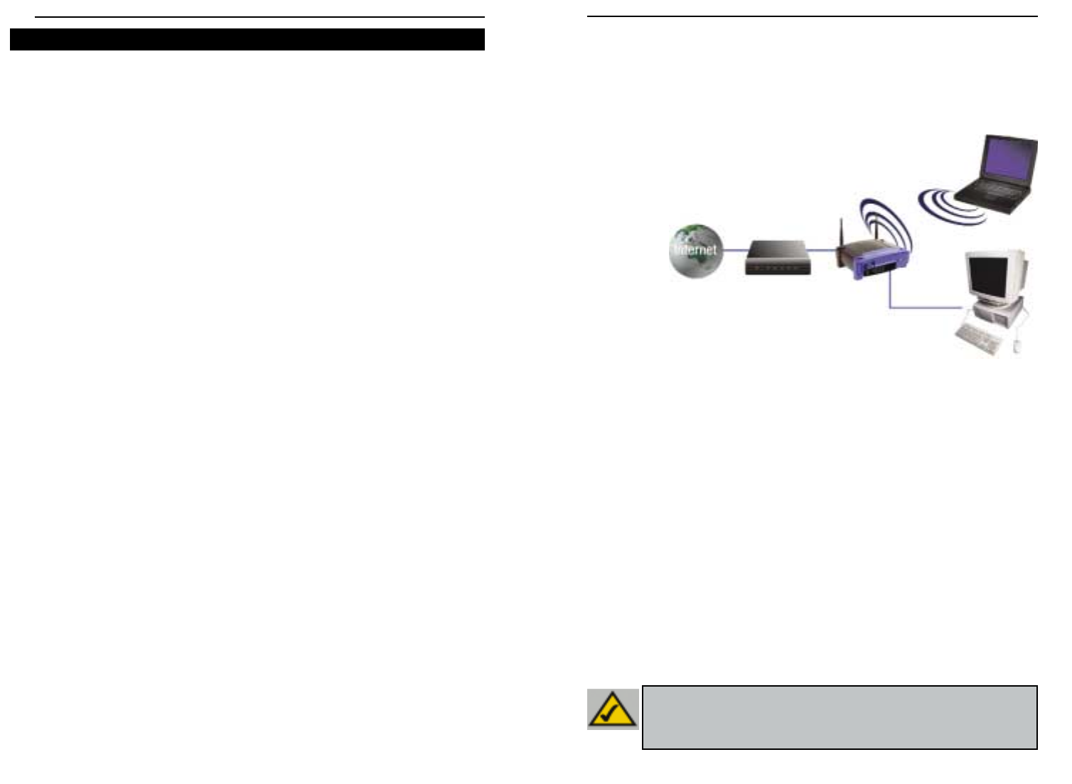
117116
Utilize as instruções neste manual de iniciação rápida para ligar o router, configurar os seus
PCs e configurar o router na sua rede. Estas instruções devem ser suficientes para colocar
uma rede básica em funcionamento e partilhar o acesso à Internet. O router também vem
equipado com funções mais avançadas,mas estas não devem ser utilizadas sem uma com-
preensão mais aprofundada do funcionamento dos routers e das redes. Estas e outras
questões são explicadas no manual do utilizador no CD-ROM do assistente de configuração.
A configuração do router é semelhante à que é mostrada na figura acima, para qualquer PC
a executar o Windows. O router permite-lhe partilhar a sua ligação por cabo ou DSL entre
vários computadores em casa ou no escritório. Esta é chamada uma rede local ou LAN (Local
Area Network).
Este manual de iniciação rápida fornece-lhe uma perspectiva geral do que é necessário para
configurar uma rede básica em casa ou no escritório. As três secções que se seguem expli-
cam como configurar o equipamento de modo a permitir a partilha do acesso de alta veloci-
dade à Internet.
Passo 1: Ligação do router
É explicado o processo de ligação do router ao modem por cabo ou DSL. Em seguida, é
mostrado como os PCs são ligados ao router.
Passo 2: Configuração dos PCs
É descrito como os PCs são configurados para comunicar com o router.
Passo 3: Configuração do router
São explicadas algumas das definições básicas do router para que funcione com o modem
por cabo ou DSL e com as definições do ISP.
Router de ponto de acesso sem fios com switch de 4 portas
Série Instant Wireless™
Obrigado por escolher o router de ponto de acesso sem fios Instant Wireless™. Este router
irá permitir-lhe configurar os seus PCs em rede e partilhar a ligação à Internet.
Como é que o router lhe permite tudo isto? Ligando o modem por cabo ou DSL directamente
ao router e utilizando as portas Ethernet do router para ligar os PCs, como se cada PC
estivesse directamente ligado à Internet. Desta forma, uma ligação à Internet pode ser uti-
lizada simultaneamente por vários PCs. Além disso,por ser também um ponto de acesso,o
router pode estabelecer uma ponte entre a rede Ethernet e os PCs sem fios.
Mas o que significa tudo isto?
As redes são ferramentas úteis para partilhar recursos informáticos. É possível aceder a
uma impressora a partir de diferentes computadores, bem como a dados localizados no
disco rígido de outro computador. As redes são também usadas para jogos de computador
multi-jogador. Então, conclui-se que as redes não só são muito úteis em casa e no
escritório,como podem ser também muito divertidas.
Os PCs ligados às quatro portas LAN do router, depois de adequadamente configurados,
constituem uma rede local (LAN:Local Area Network). Os computadores são ligados através
de um cabo Ethernet que é ligado, numa extremidade, ao adaptador de Ethernet do com-
putador e, na outra extremidade,a uma das portas LAN do router (numeradas de um a qua-
tro). O termo “Ethernet”é utilizado para designar os acessórios de rede, tais como cabos e
adaptadores, porque Ethernet se refere ao tipo de rede que está a ser configurado. Na do-
cumentação do router,Ethernet refere-se aos acessórios que transferem os dados do com-
putador de 10Mbps a 100Mbps. (10Mbps e 100Mbps referem-se às velocidades utilizadas
pelos dispositivos de rede. Ao transferir dados a 10Mbps, está a mover o equivalente a mais
de sete disquetes por segundo! Os acessórios de rede que funcionam a 100Mbps movem
os dados dez vezes mais rapidamente!)
Os PCs também podem interagir com o router sem fios. Ao configurar os PCs sem fios uti-
lizando as mesmas definições sem fios do router, é possível estabelecer uma ponte entres
estes PCs sem fios, integrando-os na rede Ethernet existente.
A funcionalidade mais espantosa do router é, talvez, o facto de permitir partilhar a ligação
por cabo ou DSL. Poderá usufruir desta funcionalidade ligando o modem por cabo ou DSL
à porta WAN do router por meio de um cabo Ethernet (WAN refere-se a uma rede alargada:
Wide Area Network). A Internet é uma rede global que abrange a maior área possível! Os
PCs ligados ao router partilham esta ligação.
Introdução
NNoottaa::Este manual de iniciação rápida irá ajudá-lo a configurar o router com cabos
Ethernet. Apesar de ser possível configurar o router através de uma ligação sem fios,
este manual de iniciação rápida não fornece pormenores sobre como configurar o
router sem fios. Os utilizadores que pretendem configurar o router através de uma lig-
ação sem fios deverão consultar o Web site da Linksys em www.linksys.com.
Esquema de configuração:

119118
No passo 1, irá ligar o router ao modem por cabo ou DSL e aos computadores de
casa ou do escritório.
Primeiro,certifique-se de que todos os dispositivos com que está a trabalhar estão
desligados da corrente incluindo os PCs, o modem e o router.
A. Se ainda não o fez, ligue o modem por cabo ou DSL à ligação adequada—a tomada
coaxial para cabo (figura A1) ou a tomada de telefone para DSL (figura A2) (Siga as
instruções do manual de instalação do modem por cabo ou DSL.)
Série Instant Wireless™
B. Utilizando um cabo Ethernet, ligue a porta
LAN ou Ethernet do modem por cabo ou DSL
à porta WAN do router.
C. Ligue um cabo Ethernet ao adap-
tador de Ethernet do PC. Ligue a
outra extremidade do cabo a uma
das portas LAN do router. Repita
este processo para cada PC que
pretender ligar ao router.
Nota: Se o adaptador de Ethernet do PC não estiver configurado, consulte a documen-
tação do adaptador de Ethernet para obter mais informações.
De modo a facilitar a instalação,comece pela
porta LAN 1 do router, utilize em seguida a
porta 2, depois a porta 3 e, finalmente, a
porta 4.
Se pretender ligar mais de quatro PCs ao
router, será necessário ligar um hub ou
switch à porta Uplink do router (se utilizar a
porta Uplink, não poderá utilizar a porta 4).
Para obter informações sobre o Uplink,con-
sulte o manual do utilizador no CD-ROM do
assistente de configuração.
D. Ligue o adaptador de corrente à porta de ali-
mentação do router. Em seguida, ligue o adaptador de corrente a uma tomada eléctri-
ca. Ligue o modem por cabo ou DSL. Em seguida,ligue o primeiro PC que pretender uti-
lizar ao configurar o router.
Prossiga para o passo 2: Configuração dos PCs, na página seguinte.
Router de ponto de acesso sem fios com switch de 4 portas
A1A2
Passo 1: Ligação do router
B
C1
C2

121120
No passo 2, irá configurar cada um dos computadores para comunicarem com o router.
Para tal, será necessário configurar as definições de rede do PC de modo a obter um
endereço IP (ou TCP/IP) automaticamente. Os computadores utilizam os endereços IP para
comunicar uns com os outros através de uma rede ou da Internet.
Descubra que sistema operativo está a ser executado pelo computador, como Windows 95,
98, Millennium, 2000 ou XP. Será necessário saber qual o sistema operativo utilizado pelo
computador. Para tal,clique no botão Iniciar e seleccione a opção Definições. (Se o menu
‘Iniciar’ não tiver uma opção ‘Definições’,significa que está a utilizar o Windows XP. É pos-
sível seleccionar ‘Painel de controlo’ directamente a partir do menu ‘Iniciar’.) Em seguida,
clique em Painel de controlo e faça duplo clique no ícone Sistema. Clique no botão
Cancelar quando terminar.
Depois de saber qual o sistema operativo do Windows a ser executado pelo computador,
siga as instruções neste passo adequadas ao seu sistema operativo. Poderá ser necessário
repetir este procedimento para todos os computadores que ligar ao router.
As páginas que se seguem informam-no, passo a passo, sobre como configurar as
definições TCP/IP com base no tipo de sistema operativo do Windows que está a utilizar.
Depois de configurar os computadores, prossiga para o passo 3: Configuração do router.
A. Clique no botão Iniciar, clique em Definições
e abra o Painel de controlo. A partir daí, faça
duplo clique no ícone Rede para abrir o ecrã
‘Rede’.
B. Seleccione o separador ‘Configuração’ e clique
na Linha TCP/IP para o adaptador de Ethernet
aplicável*. Se a palavra TCP/IP aparecer soz-
inha, seleccione essa linha**. Em seguida,
clique no botão Propriedades.
C. Clique no separador Endereço IP e seleccione
Obter automaticamente um endereço IP.
D. Clique no separador Gateway e verifique se o
campo ‘Gateway instalada’ está em branco.
Clique no botão OK.
E. Clique novamente no botão OK. O Windows
poderá solicitar-lhe o disco de instalação
original do Windows ou ficheiros adicionais.
Forneça-os apontando a localização correcta
do ficheiro, por exemplo, D:\win98, D:\win9x,
c:\windows\options\cabs, etc. (sendo “D” a
letra da unidade de CD-ROM).
F. Se o Windows lhe perguntar se pretende reiniciar o computador, clique no botão Sim.
Se o Windows não lhe solicitar que reinicie o computador, faça-o ainda assim.
*Nota: Não escolha uma entrada TCP/IP cujo nome mencione DUN,PPPoE,VPN, ou AOL.
**Nota: Se não existir uma linha TCP/IP listada,consulte o manual do utilizador no CD-ROM
do assistente de configuração ou a documentação do adaptador de Ethernet para insta-
lar o TCP/IP.
Série Instant Wireless™ Router de ponto de acesso sem fios com switch de 4 portas
Passo 2: Configuração dos PCs Se estiver a utilizar:
Windows 95, Windows 98, Windows Me
B
C
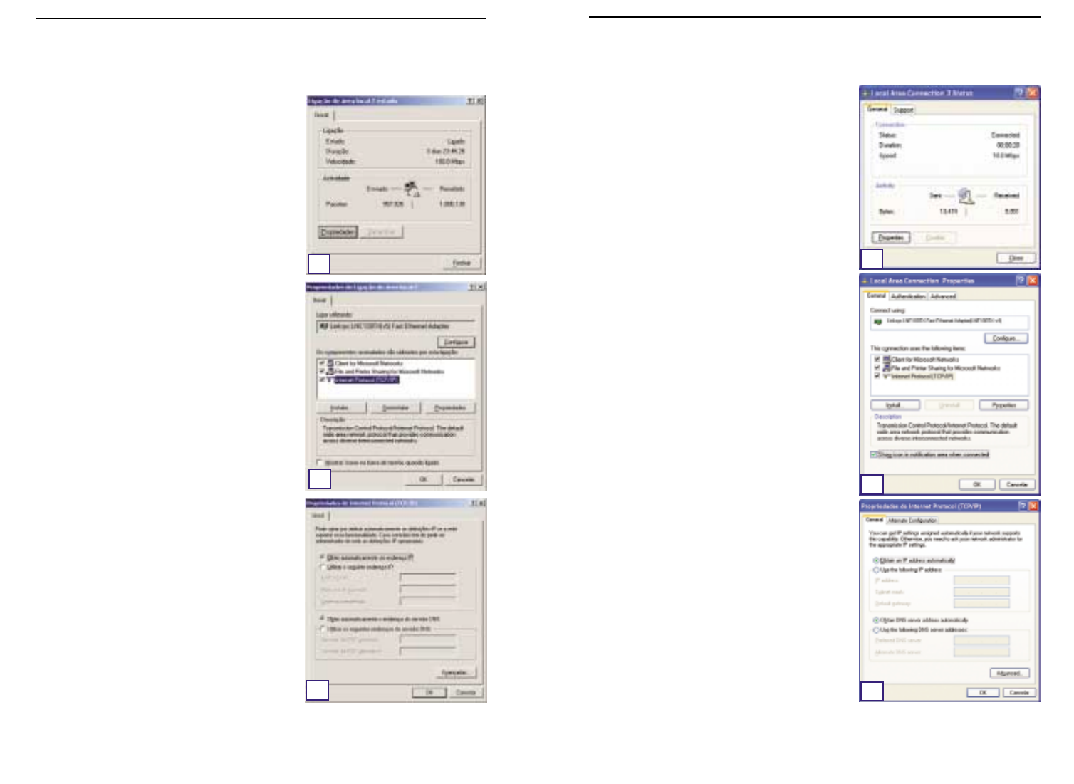
123122
As instruções que se seguem assumem que está a
ser executada a interface predefinida do Windows
XP. Se estiver a utilizar a interface clássica (em que
os ícones e menus se assemelham às versões ante-
riores do Windows), siga as instruções para o
Windows 2000.
A. Clique no botão Iniciar, abra o Painel de con-
trolo e clique no ícone Ligações de Internet e
de rede. Em seguida, clique no ícone Ligações
de rede para apresentar o ecrã ‘Rede’.
B. Seleccione o ícone Ligação de rede local para
o adaptador de Ethernet (normalmente, é a
primeira ligação de rede local listada). Faça
duplo clique em Ligação de rede local.
C. Quando o ecrã ‘Estado da ligação de rede local’
aparecer, clique no botão Propriedades.
D. Seleccione Protocolo Internet (TCP/IP) e
clique no botão Propriedades.
E. Seleccione Obter automaticamente um
endereço IP e clique no botão OK nos ecrãs
subsequentes para concluir a configuração do
PC.
F. Reinicie o computador.
A. Clique no botão Iniciar, clique em Definições e
abra o Painel de controlo. A partir daí, faça
duplo clique no ícone Ligações de acesso tele-
fónico e de rede. Será apresentado o ecrã
‘Rede’.
B. Seleccione o ícone Ligação de rede local para
o adaptador de Ethernet* (normalmente, é a
primeira ligação de rede local listada). Faça
duplo clique em Ligação de rede local.
C. Quando o ecrã ‘Estado da ligação de rede local’
aparecer, clique no botão Propriedades.
D. Seleccione Protocolo Internet (TCP/IP) e
clique no botão Propriedades.
E. Seleccione Obter automaticamente um
endereço IP e clique no botão OK nos ecrãs
subsequentes para concluir a configuração do
PC.
F. Reinicie o computador.
*Nota: Não escolha uma entrada TCP/IP cujo nome
mencione DUN,PPPoE,VPN, ou AOL.
Série Instant Wireless™ Router de ponto de acesso sem fios com switch de 4 portas
Se estiver a utilizar:
Windows 2000
E
D
C
Se estiver a utilizar:
Windows XP
C
D
E
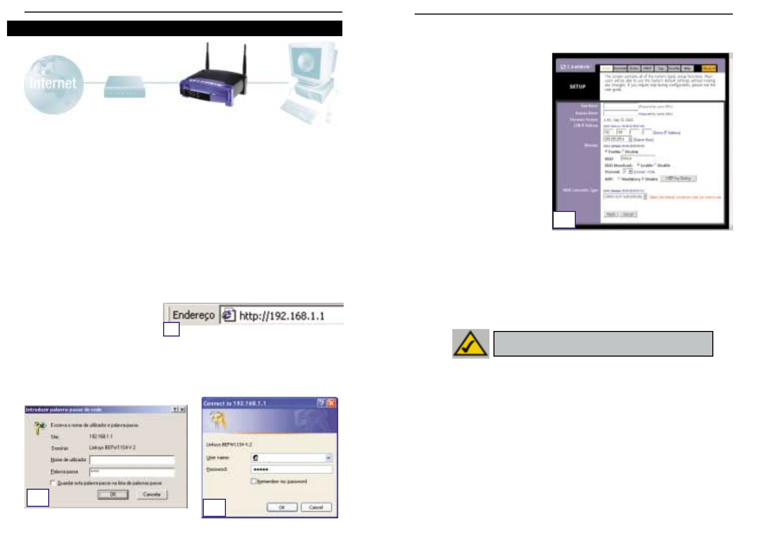
125124
C. Se for exigido pelo ISP,introduza o nome de anfitrião e o nome de domínio nos campos
Host Name e Domain Name, respectivamente, no separador ‘Setup’ (Configuração).
(Este procedimento é normalmente exigido pelos ISPs de cabo.)
D. Para configurar o router para a
sua rede sem fios, verifique se
os campos ‘Wireless’ (Sem fios)
no separador ‘Setup’
(Configuração), apresentados na
figura D, estão preenchidos da
seguinte forma:
Enable/Disable(Activar/desacti-
var): Se seleccionar o botão de
opção Enable (Activar), irá acti-
var a funcionalidade sem fios do
router. As funções sem fios só
estarão disponíveis se forem
activadas.
SSID: O SSID (ou ESSID) é um nome exclusivo para a sua rede sem fios. É sensível a
maíusculas/minúsculas e não pode ultraassar os 32 caracteres. O SSID predefinido é
“linksys “ mas deverá atribuir um nome pessoal à rede sem fios. É necessário que
todos os pontos na rede sem fios utilizem o mesmo SSID.
Channel (Canal):Seleccione o canal apropriado para a sua rede a partir da lista forneci-
da. É necessário que todos os pontos na rede sem fios utilizem o mesmo canal para
funcionarem correctamente.
E. O router suporta cinco tipos de ligações: DHCP (obtain an IP automatically) (DHCP, obter
automaticamente um endereço IP),PPPoE, Static IP Address (Endereço IP estático),RAS
e PPTP. Estes tipos são seleccionados a partir do menu pendente junto a WAN
Connection Type (Tipo de ligação WAN). O ecrã de configuração e as funcionalidades
disponíveis dependem do tipo de ligação seleccionado,apresentando-se em seguida as
instruções para cada um deles:
1. Obter automaticamente um endereço IP
Se o ISP lhe disser que está a ligar através de um endereço IP dinâmico (ou DHCP),efectue
os seguintes procedimentos:
a. Seleccione Obtain an IP automatically (Obter automaticamente um endereço IP)
como tipo de ligação WAN (tal como foi anteriormente mostrado na figura D).
b. Clique no botão Apply (Aplicar) para guardar as definições.
No passo 3,irá configurar o router para funcionar em rede e obter acesso à Internet através
do seu fornecedor de serviços Internet (ISP). O ISP pode requerer o uso de um nome de
anfitrião e nome de domínio. Em seguida, irá definir o tipo de configuração WAN no sepa-
rador de configuração do router, a partir das informações fornecidas pelo ISP.
É necessário
obter estas informações de configuração junto do ISP.
Se não possuir estas informações,
contacte o ISP antes de prosseguir. Para saber que questões deve colocar ao ISP, consulte
a pergunta n.º 1 na secção ‘Ajuda’.
As instruções do ISP informam-no sobre como configurar o PC para acesso à Internet. Uma
vez que está a utilizar o router para partilhar o acesso à Internet entre diversos computa-
dores, estas informações de configuração serão necessárias para configurar o router.
A. Abra o Web browser (não se preocupe se receber uma mensagem de erro nesta altura.
Continue a seguir as instruções). Introduza 192.168.1.1 no campo ‘Endereço’ do Web
browser e prima a tecla Enter.
B. Irá aparecer uma janela para introduzir a palavra-passe da rede,mostrada na figura B1.
(Os utilizadores do Windows XP irão ver a janela ‘Ligar a 192.168.1.1’, mostrada na figu-
ra B2.). Deixe o campo ‘User Name’ (Nome de utilizador) vazio e introduza admin (a
palavra-passe predefinida),em minúsculas, no campo ‘Password’. Em seguida, clique
no botão OK.
Série Instant Wireless™ Router de ponto de acesso sem fios com switch de 4 portas
Passo 3: Configuração do router
A
B1B2
D
NNoottaa:: Se estiver interessado em alterar as definições WEP do router,
consulte a secção ‘Configurar a segurança sem fios’.
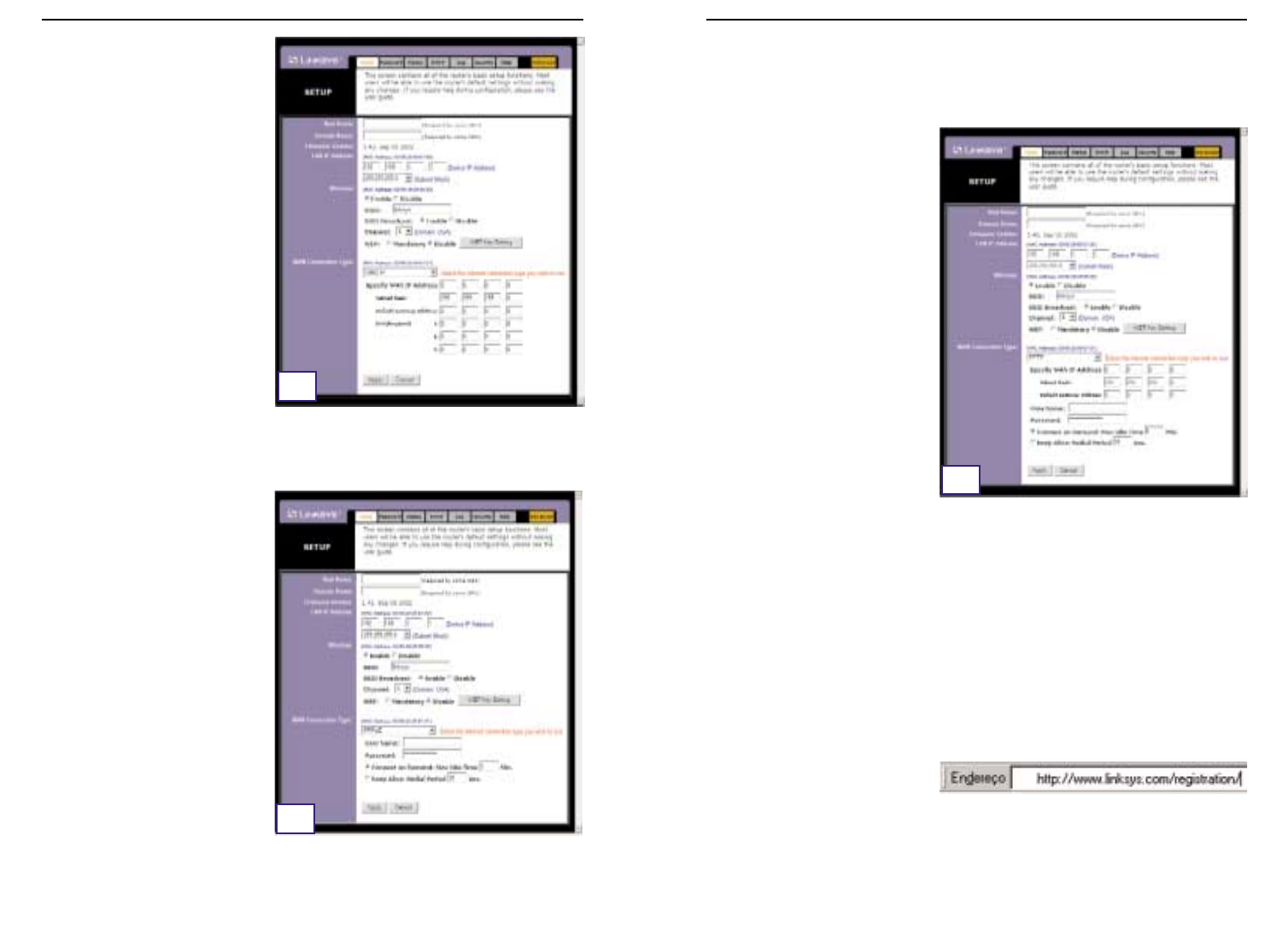
127126
Router de ponto de acesso sem fios com switch de 4 portas
4. RAS
O RAS é um serviço utilizado apenas em Singapura. Se estiver a utilizar uma ligação RAS,
consulte o seu ISP para obter as informações de configuração necessárias.
5. PPTP
O PPTP é um serviço utilizado apenas
na Europa. Se estiver a utilizar uma
ligação PPTP, consulte o seu ISP para
obter as informações de configuração
necessárias.
F. Se ainda não o tiver feito,clique no botão Apply (Aplicar) para guardar as definições.
G. Desligue e volte a ligar o modem por cabo ou DSL à corrente e reinicie os computa-
dores. Os computadores irão obter as novas definições do router.
Nota: Só é necessário configurar o router a partir de um computador. Para obter infor-
mações de configuração avançadas,consulte o Web site de suporte da Linksys em
sup-
port.linksys.com
ou o manual do utilizador no CD-ROM do assistente de configuração.
Parabéns! Concluiu com êxito a configuração do router. Pode testar a configuração
abrindo o Web browser a partir de qualquer computador e entrando em
www.linksys.com/registration
.
Se não conseguir ir ao nosso Web site, reveja os procedimentos efectuados nesta secção
ou consulte a secção de ajuda deste manual de iniciação rápida.
Série Instant Wireless™
2. IP estático
Se o ISP lhe disser que está a ligar
através de um endereço IP estático (ou
fixo), efectue os seguintes procedi-
mentos:
a. Seleccione Static IP (IP estático)
como tipo de ligação WAN.
b.
Nos campos junto a ‘Specify WAN IP
Address’ (Especificar endereço IP
da WAN), introduza o endereço IP.
c. Introduza a Subnet Mask
(Máscara de sub-rede).
d. Introduza o Default Gateway
Address (Endereço da gateway
predefinida).
e. Introduza o DNS nos campos 1, 2,
e/ou 3. É necessário introduzir
pelo menos um endereço de DNS.
f. Clique no botão Apply (Aplicar) para guardar as definições.
3. PPPoE
Se o fornecedor de DSL lhe disser que
está a ligar através de PPPoE ou se cos-
tuma introduzir um nome de utilizador e
palavra-passe para aceder à Internet,
efectue os seguintes procedimentos:
a. Seleccione PPPoE como tipo de
ligação WAN.
b. Introduza o User Name (Nome de
utilizador).
c. Introduza a Password (Palavra-
passe).
d. Clique no botão Apply (Aplicar)
para guardar as definições.
e. Clique no separador Status
(Estado), seguido do botão
Connect (Ligar) para estabelecer a ligação.
E2
E3
E5

128 129
Router de ponto de acesso sem fios com switch de 4 portas
2. Estou a ter problemas para ligar à Internet.Que LEDs devem acender na parte da
frente do router?
•Cada LED do router irá acender por cada ligação bem estabelecida na parte de trás do
router—quer seja um cabo Ethernet ou um cabo de alimentação.
Por exemplo,os seguintes LEDs acendem quando se liga um computador e um modem
por cabo ou DSL:
- Quando o router é ligado (o adaptador de corrente está ligado ao
router), o LED
Power
acende.
- Quando um cabo Ethernet é correctamente ligado entre um PC e a porta 4 do
router, os LEDs
Link/Act
,
Ful/Col
e
100
na coluna 4 acendem.
- A ligação de um modem por cabo ou DSL faz com que o LED
WAN Link
acenda.
Série Instant Wireless™
A secção de ajuda contém as perguntas mais frequentes relacionadas com a ligação à
Internet. Se tiver necessidades de configuração adicionais ou pretender obter informações
acerca das funcionalidades avançadas, visite
kb.linksys.com
ou consulte o manual do uti-
lizador, que contém um anexo dedicado à resolução de problemas (disponível no CD-ROM
do assistente de configuração).
1. Não tenho a certeza sobre as informações que necessito de obter junto do meu
fornecedor de serviços Internet (ISP) para colocar a rede a funcionar. Que
questões devo colocar?
Que tipo de ligação tenho: endereço IP dinâmico, endereço IP estático ou PPPoE?
•Se estiver a utilizar um endereço IP dinâmico,devo perguntar:
- Qual é o meu nome de anfitrião (se necessário)?
- Qual é o meu nome de domínio (se necessário)?
•Se estiver a utilizar um endereço IP estático,devo perguntar:
- Qual é o meu endereço IP?
- Qual é a minha gateway?
- Qual é o meu DNS?
•Se estiver a utilizar PPPoE (tipicamente utilizado por ISPs de DSL), devo perguntar:
- Qual é o meu nome de utilizador?
- Qual é a minha palavra-passe?
Depois de obter as informações, siga as instruções indicadas no passo 3 do manual de ini-
ciação rápida,‘Configuração do router’,e introduza estas informações no separador ‘Setup’
(Configuração). Na secção ‘WAN Connection Type’ (Tipo de ligação WAN),consulte o gráfico
na página seguinte:
Ajuda ?Dynamic IP Address
(DHCP) (Endereço IP
dinâmico, DHCP)
1. Seleccione Obtain an IP automatically (Obter automatica-
mente um endereço IP) como tipo de ligação WAN .
2. Clique no botão Apply (Aplicar) para guardar as definição.
Efectue os seguintes procedimentos:
PPPoE 1. Seleccione PPPoE como tipo de ligação WAN .
2. Introduza o User Name (Nome de utilizador).
3. Introduza a Password (Palavra-passe).
4. Clique no botão Apply (Aplicar) para guardar as definição.
Static IP Address
(Endereço IP estáti-
co)
1. Seleccione Static IP (IP estático) como tipo de ligação WAN .
2. Introduza o IP Address (Endereço IP).
3. Introduza a Subnet Mask (Máscara de sub-rede).
4. Introduza o Gateway Address (Endereço de gateway).
5. Inrroduza o DNS nos campos 1, 2,e/ou 3. É necessário intro-
duzir pelo menos um endereço de DNS.
6. Clique no botão Apply (Aplicar) para guardar as definição.
RAS ou PPTP Se estiver a utilizar RAS (SingTel na Singapura) ou PPTP (serviço
na Europa),consulte o seu ISP para obter as informações de con-
figuração necessárias.
Se tiver este tipo de
ligação:

131130
Router de ponto de acesso sem fios com switch de 4 portas
•O campo ‘Endereço IP’ deve mostrar 192.168.1.100 ou 192.168.1.xxx, sendo
“xxx” qualquer número superior a 100. Se o seu endereço IP não estiver dentro
desse intervalo, mantenha o botão ‘Reset’ na parte da frente do router premido
durante mais de 30 segundos. Isto fará com as predefinições de fábrica sejam
repostas, de forma que será necessário voltar a configurar a página de configu-
ração do router. Depois de configurar novamente a página de configuração,reini-
cie o computador.
C. Em seguida, irá configurar algumas definições em Windows.
- No ambiente de trabalho,faça duplo clique em O meu computador e, em seguida,faça
duplo clique em Painel de controlo (Os utilizadores do Windows XP com a interface
predefinida devem clicar em Iniciar e seleccionar Painel de controlo).
- Quando a janela do painel de controlo aparecer, faça duplo clique no ícone Opções da
Internet (os utilizadores do Windows XP com a interface predefinida devem clicar em
Ligações de Internet e de rede e, em seguida, em Opções da Internet).
- Quando a janela ‘Opções da Internet’ aparecer, clique no separador Ligações.
- Seleccione Nunca estabelecer uma ligação (está tudo bem se esta opção não estiv-
er disponível).
- Clique no botão Definições da rede local… no canto inferior direito.
- Quando a janela ‘Definições da rede local’ aparecer,desmarque todas as caixas.
- Clique no botão OK e no botão Aplicar (o botão Aplicar não poderá ser seleccionado
se não tiver efectuado nenhuma alteração). Em seguida,clique no botão OK novamente.
- Saia do painel de controlo e reinicie o computador.
4. Quando clico no ícone para aceder à Internet e introduzo o nome de utilizador e
palavra-passe fornecidos pelo ISP, não consigo estabelecer uma ligação à
Internet. O que se passa?
Se isto acontecer, significa que está a utilizar o software fornecido pelo seu ISP. Utilize o
Internet Explorer ou o Netscape Navigator, localizados no ambiente de trabalho (ou no menu
‘Iniciar’ no Windows XP).
5. Quando utilizo o Internet Explorer, aparece uma caixa a solicitar que estabeleça
uma ligação de acesso telefónico. Como posso desactivar essa opção?
A. No ambiente de trabalho,faça duplo clique em O meu computador e, em seguida,faça
duplo clique em Painel de controlo (Os utilizadores do Windows XP com a interface
predefinida devem clicar em Iniciar e seleccionar Painel de controlo).
B. Quando a janela do painel de controlo aparecer, faça duplo clique no ícone Opções da
Internet (os utilizadores do Windows XP com a interface predefinida devem clicar em
Ligações de Internet e de redee, em seguida, em Opções da Internet).
C. Quando a janela ‘Opções da Internet’ aparecer, clique no separador Ligações.
Série Instant Wireless™
•O LED
WAN Link
não está aceso. O que devo verificar?
- Verifique se o cabo que está a usar entre o modem por cabo ou DSL e o router é
o que foi fornecido com o modem. Consoante o tipo de ligação utilizada pelo
modem, poderá necessitar de um cabo Ethernet directo (‘straight-through’) ou
cruzado (‘crossover’). O tipo directo é o mais comum.
•Algumas das luzes na parte da frente do router não acendem quando eu ligo um PC.
- Apenas o LED
Link/Act
é necessário para que uma ligação funcione correcta-
mente.
3. Não consigo aceder à Internet nem à página de configuração do router. O que
devo veri-ficar?
A. Em primeiro lugar, verifique se o modem por cabo ou DSL e os computadores estão cor-
rectamente ligados ao router. Consulte a pergunta n.º 2 para obter informações sobre
como verificar se as ligações estão correctas.
B. Em seguida, verifique se configurou correctamente os PCs para comunicarem com o
router. Abaixo poderá encontrar instruções referentes às diversas versões do Windows.
-Windows 95, 98 ou ME
•Clique no menu Iniciar e, em seguida, clique em Executar. Quando aparecer a
janela ‘Executar’, introduza winipcfg no campo ‘Abrir’ e, em seguida, clique no
botão OK.
•Quando aparecer a janela ‘Configuração IP’, clique na caixa cinzenta com
uma seta preta a apontar para baixo.
•Irá aparecer uma lista de adaptadores. Seleccione o adaptador que utiliza para
se ligar à Internet. Estes itens não devem conter “PPP”, “VPN”, “AOL” ou
“Adaptador de acesso telefónico” como parte da entrada.
•O campo ‘Emdereço IP’ deve mostrar 192.168.1.100 ou 192.168.1.xxx, sendo
“xxx” qualquer número superior a 100. Se o seu endereço IP não estiver dentro
desse intervalo, mantenha o botão ‘Reset’ na parte da frente do router premido
durante mais de 30 segundos. Isto fará com as predefinições de fábrica sejam
repostas, de forma que será necessário voltar a configurar a página de configu-
ração do router. Depois de configurar novamente a página de configuração,reini-
cie o computador.
-Windows NT, 2000 e XP
•Clique no menu Iniciar e, em seguida, clique em Executar. Quando aparecer a
janela ‘Executar’, introduza cmd no campo ‘Abrir’ e,em seguida, clique no botão
OK.
•Irá aparecer uma linha de comandos. Introduza ipconfig /all e, em seguida,
prima a tecla Enter.
133132
Router de ponto de acesso sem fios com switch de 4 portas
Série Instant Wireless™
D. Seleccione Nunca estabelecer uma ligação.
E. Clique no botão Aplicar.
F. Clique no botão OK.
6. Não obtenho intensidade do sinal nem qualidade da ligação. O que posso fazer?
A. Verifique se o LED WLAN do router está iluminado.
B. Verifique se todos os PCs sem fios estão a utilizar o modo ‘Infrastructure’.
7. Como posso aumentar a amplitude do router?
A. Coloque o router tão elevado do chão quanto possível.
B. Verifique se não existem fontes de interferência eléctrica significativa nas proximi-
dades. (Por exemplo: caixas de altifalantes, luzes fluorescentes, microondas,etc.)
C. Mude o canal sem fios utilizado. Para o fazer:
- Abra o Web browser e escreva http://192.168.1.1 no campo ‘Endereço’.
- Na caixa ‘Enter Network Password’ (Introduzir palavra-passe da rede), deixe o campo
do nome de utilizador em branco e escreva a palavra-passe admin. Em seguida, clique
em OK.
- No separador ‘Setup’ (Configuração), mude o canal para 1.
- Clique no botão Apply (Aplicar) para guardar as definições.
- Continue a efectuar este procedimento até encontrar o canal que forneça a maior
amplitude.
Sendo um acrónimo para privacidade equivalente com fios (WEP: Wired Equivalent
Privacy), este constitui um método de encriptação utilizado para proteger as comuni-
cações de dados sem fios. A WEP utiliza uma combinação de chaves de 64 ou 128 bits
para proporcionar o controlo do acesso à sua rede e segurança de encriptação para todas
as transmissões de dados. Para descodificar uma transmissão de dados, cada ponto na
rede tem de utilizar uma chave de 64 ou 128 bits idêntica. Níveis de encriptação supe-
riores significam maiores níveis de segurança, mas devido à complexidade da encrip-
tação, podem também significar uma diminuição no desempenho da rede.
Também poderá ter ouvido falar no termo “40 bits” utilizado em associação com encrip-
tação WEP . Este é outro termo para encriptação WEP de 64 bits . Este nível de encrip-
tação WEP foi apelidado de 40 bits porque utiliza uma chave secreta de 40 bits junta-
mente com um vector de inicialização de 24 bits (40 + 24 = 64). Os fornecedores de
equipamento sem fios poderão usar qualquer um dos nomes. A Linksys utiliza o termo
“64 bits” para se referir a este nível de encriptação.
Certifique-se de que a rede sem fios está a funcionar antes de tentar configurar a encrip-
tação WEP.
Uma rede sem fios com encriptação WEP de 128 bits NÃO comunicará com uma rede
sem fios com encriptação WEP de 64 bits. Por isso, certifique-se de que todos os dis-
positivos sem fios utilizam o mesmo nível de encriptação. Todos os dispositivos sem
fios em conformidade com a norma 802.11b suportam WEP de 64 bits.
Para além da activação da WEP, a Linksys também recomenda a implementação das
seguintes medidas de segurança:
•Alteração do SSID cujo valor predefinido é “linksys”
•Alteração regular da chave WEP
Nota: A encriptação WEP é uma medida adicional de
segurança de dados não essencial para o funcionamento
do router.
Nota: Para activar a encriptação WEP, é necessário activar, em primeiro lugar,
as funções sem fios. Seleccione Enable (Activar) no separador ‘Wireless’
(Sem fios) antes de prosseguir.
Configurar a segurança sem fios
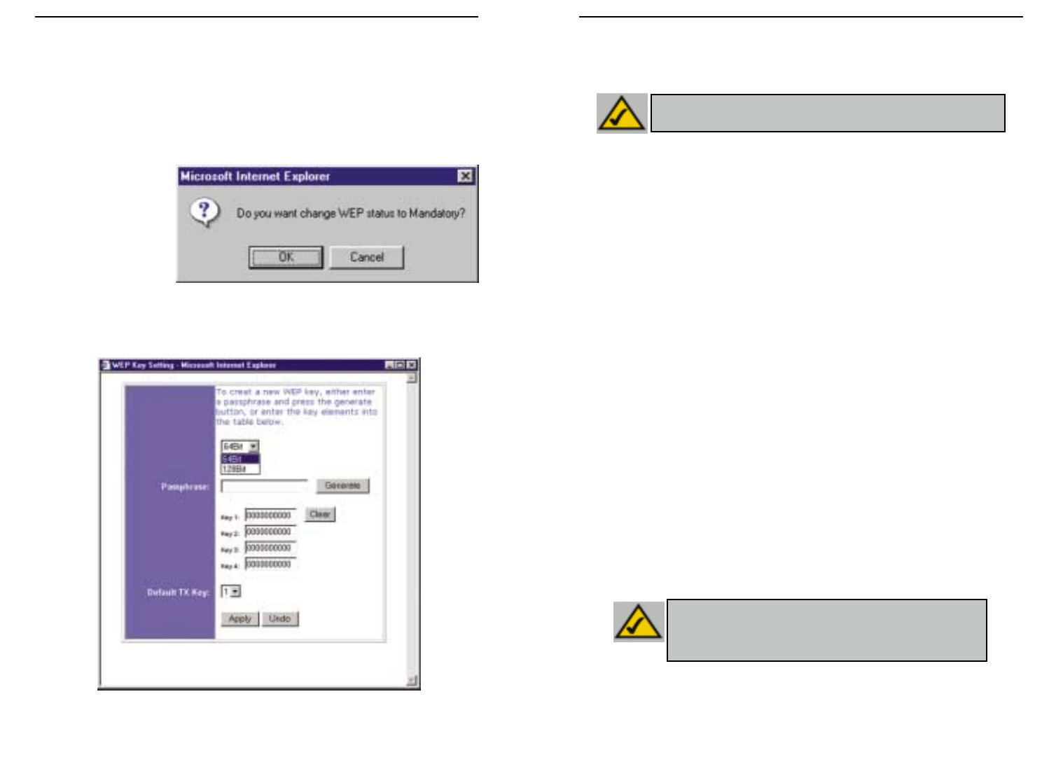
135134
Router de ponto de acesso sem fios com switch de 4 portas
Série Instant Wireless™
• WEP (64B ou 128B) Seleccione o nível de encriptação a partir da caixa pendente.
A encriptação WEP de 128 bits é exclusiva da Linksys e pode entrar em conflito
com a encriptação WEP de outros fornecedores.
A chave de encriptação WEP é gerada de uma das seguintes formas:
1. O utilizador pode criar uma chave de encriptação utilizando uma Passphrase (Frase-
passe).
a. Introduza uma frase-passe, uma palavra-passe definida pelo utilizador, no campo
Passphrase. A frase-passe pode conter até 31 letras, símbolos e números. Não é
possível utilizar espaços.
b. Clique no botão Generate (Gerar) para criar uma chave. A chave terá 10 dígitos,
se escolher encriptação de 64 bits ou 26 dígitos, se escolher encriptação de 128
bits. Esta chave será utilizada para encriptar e desencriptar os dados enviados
entre o router e os PCs sem fios da rede.
O campo ‘Key’ (Chave) pode não apresentar todos os dígitos. Com o rato, clique
em qualquer parte no campo ‘Key’ (Chave). Mova o cursor para a direita para
ver o resto da chave. Certifique-se de que escreve toda a chave EXACTA-
MENTE da forma como é mostrada.
2. Pode introduzir a chave de encriptação manualmente.
Tome nota da frase-passe ou chave manual. Ela será necessária para os outros disposi-
tivos sem fios da rede, uma vez que todos têm de possuir a mesma chave de encriptação
WEP.
Uma vez escolhido o método da chave de encriptação e introduzida a frase-passe ou
chave manual, clique no botão Apply (Aplicar) para concluir a parte do processo de
configuração destinada à encriptação.
Nota: Para utilizar a encriptação WEP, todos os pontos na rede sem
fios têm de ter a WEP activada e possuir a mesma definição de chave.
Nota: No Windows XP, uma chave de 128 bits gerada pelo
router será designada por chave de “104 bits (26 dígitos)” e
uma chave de 64 bits gerada pelo router será designada por
chave de “40 bits (10 dígitos)” .
Os passos que se seguem irão mostrar como utilizar a encriptação WEP
1. A partir do separador ‘Setup’ (Configuração) do utilitário baseado na Web, selec-
cione Mandatory (Obrigatório) na secção WEP.
2. Prima o botão WEP Key Setting (Definição da chave WEP) para definir o tipo e o
nível da encriptação WEP.
3. Poderá aparecer o
ecrã apresentado na
figura C-1, a confir-
mar se pretende acti-
var a encriptação
WEP. Prima o botão
OK para continuar.
4. Em seguida, será apresentado o ecrã mostrado na figura C-2. A partir daqui, poderá
escolher as suas definições de encriptação WEP.
Figura C-2
Figura C-1
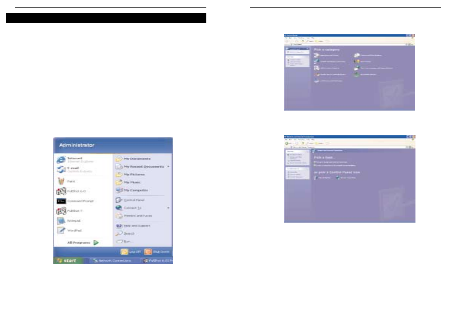
137136
Router de ponto de acesso sem fios com switch de 4 portas
Série Instant Wireless™
2. Na janela do painel de controlo, clique no ícone Ligações de Internet e de rede
mostrado na figura C-4.
3. Clique no ícone Ligações de rede mostrado na figura C-5.
4. A janela “Ligações de rede” irá aparecer, tal como é mostrado na figura C-6. Em
LAN ou Internet de alta velocidade, poderá ver todas as placas de rede instaladas e
a funcionar no computador. Faça duplo clique no ícone Ligação de rede sem fios
associado ao seu adaptador sem fios.
Se a janela “Estado da ligação de rede sem fios” aparecer, prossiga para o passo
seguinte.
Figura C-4
Figura C-5
Uma vez que o Windows XP não permite o uso da funcionalidade da frase-passe da
Linksys com os adaptadores sem fios, será necessário introduzir manualmente a chave
gerada na secção anterior.
Os seguintes procedimentos irão ajudá-lo a activar a WEP e introduzir manualmente a
chave de encriptação para as placas PC Card sem fios, permitindo que o sistema
Windows XP comunique com o router sem fios.
Estes procedimentos assumem que a letra da unidade de CD-ROM é ‘D’ e que o
Windows XP está a ser executado no modo predefinido.
Certifique-se de que possui a chave WEP gerada pelo router.
1. Tal como é mostrado na figura C-3, clique no botão Iniciar e vá para o Painel de
controlo.
Figura C-3
Configurar a segurança sem fios no Windows XP
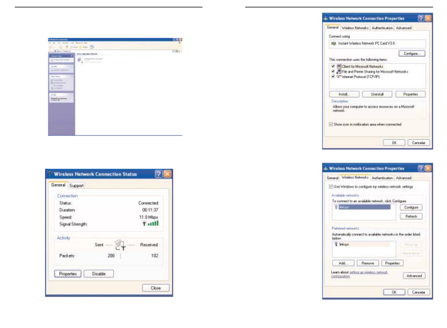
139138
Router de ponto de acesso sem fios com switch de 4 portas
Série Instant Wireless™
6. Quando a janela “Propri-
edades da ligação de rede
sem fios” aparecer, tal
como é mostrado na figura
C-8, clique no separador
Redes sem fios.
7. Se for apresentada a rede
sem fios apropriada,
especificada pelo SSID do
router, na secção “Redes
preferidas”, tal como é
mostrado na figura C-9,
faça duplo clique na
mesma e prossiga para o
passo seguinte.
Caso contrário, clique na
rede sem fios apropriada,
especificada pelo SSID do
router, na secção “Redes
disponíveis”. Em seguida,
clique no botão
Configurar.
Figura C-8
Figura C-9
Se aparecer uma janela “Ligar à rede sem fios” na secção “Redes disponíveis”,
clique na rede sem fios pretendida especificada pelo SSID do router. Em seguida,
faça duplo clique no ícone Ligação de rede sem fios.
5. Quando a janela “Estado da ligação de rede sem fios” aparecer, tal como é mostra-
do na figura C-7, clique no botão Propriedades.
Figura C-6
Figura C-7
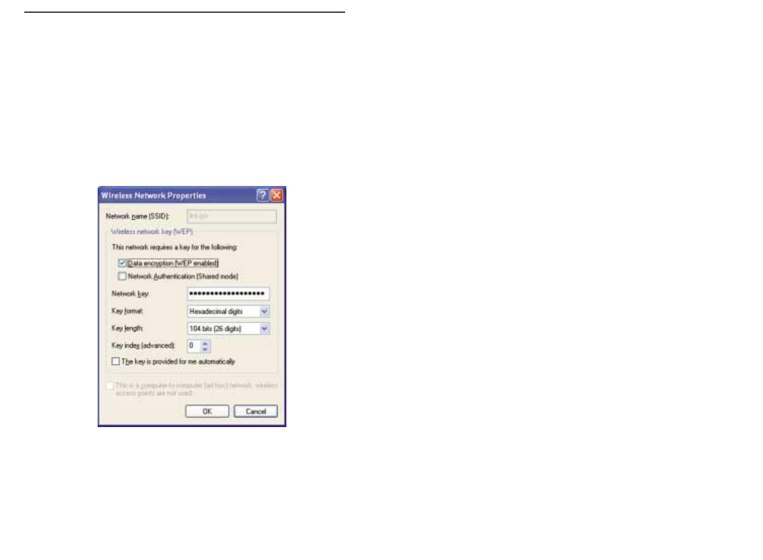
141140
Série Instant Wireless™
8. Irá aparecer a janela “Propriedades da rede sem fios” (mostrada na figura C-10).
Marque a opção Encriptação de dados (WEP activada), na caixa de verificação.
Desmarque os campos Autenticação de rede (modo partilhado) e Chave forneci-
da automaticamente.
No campo ”Chave de rede”, introduza a chave tal e qual como foi gerada pelo router
(os 10 ou 26 dígitos, consoante o nível de encriptação).
Verifique se o campo “Formato da chave” apresenta “Dígitos hexadecimais” e se o
campo “Comprimento da chave” apresenta “40 bits (10 dígitos)” ou “104 bits (26
dígitos)”. Se assim não for, significa que a chave foi introduzida incorrectamente.
Clique no botão OK para guardar as definições. Clique nos botões OK até chegar
à janela “Estado da ligação de rede sem fios”. Feche todas as janelas abertas para
regressar ao ambiente de trabalho do Windows XP.
Feche todas as aplicações e reinicie o computador. Depois de reiniciar, a configuração
WEP é concluída e deverá ser possível estabelecer uma ligação sem fios ao router.
Figura C-10

143142
COPYRIGHT Y MARCAS COMERCIALES.
Copyright © 2002 Linksys. Todos los derechos reservados. Instant Wireless es una
marca comercial de Linksys. Microsoft, Windows y el logotipo de Windows son marcas
comerciales registradas de Microsoft Corporation. Las demás marcas comerciales y
nombres de productos pertenecen a sus respectivos propietarios.
NORMATIVA DE LA FCC.
El ruteador Access Point para conexiones inalámbricas con switch de 4 puertos Instant
Wireless™ ha sido probado y cumple las especificaciones de la Clase B para disposi-
tivos digitales, con arreglo a la Sección 15 de la normativa de la FCC. Estas normas
están diseñadas para proporcionar una protección razonable contra interferencias per-
judiciales en instalaciones residenciales. Este equipo genera, utiliza y puede emitir
energía radioeléctrica. Si no se instala y utiliza según las instrucciones, podría causar
interferencias perjudiciales en las comunicaciones por radio. No obstante, no se garan-
tiza que no se produzcan interferencias en una instalación concreta. Si este equipo lle-
gara a producir interferencias perjudiciales para la recepción de radio o televisión,
detectadas al encender y apagar el equipo, se recomienda tomar las medidas sigu-
ientes para corregirlas:
• Reoriente o cambie la ubicación de la antena receptora
• Aumente la distancia entre los equipos o los dispositivos
• Conecte el equipo a un enchufe distinto al del receptor
• Consulte a un distribuidor o técnico especializado de radio y TV
Índice de materias
Introducción 144
Paso 1: Conexión del ruteador 146
Paso 2: Configuración de los PC 148
Paso 3: Configuración del ruteador 152
Ayuda 156
Configuración de la seguridad inalámbrica 161
Configuración de la seguridad inalámbrica en
Windows XP 164
Si necesita asistencia técnica sobre los productos, póngase en contacto con
nosotros en las direcciones siguientes:
correo electrónico europe-support@linksys.com
latam-soporte@linksys.com
Web http://www.linksys.com/international
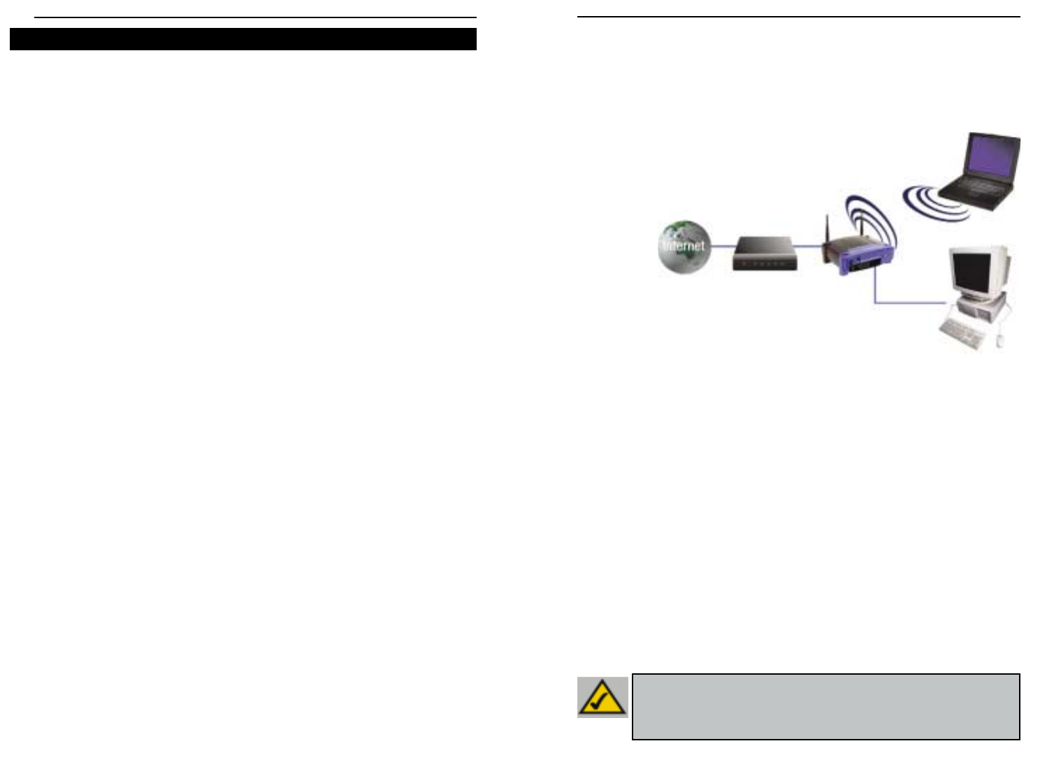
145144
Siga las instrucciones de esta Guía rápida para conectar el ruteador y configurar los PC y el
ruteador en la red. En estas instrucciones se explican todos los pasos necesarios para con-
figurar y poner en marcha una red normal y compartir el acceso a Internet. El ruteador dispone
también de otras funciones más avanzadas,no obstante,no deberán utilizarse hasta no tener
un conocimiento más amplio de ruteadores y redes. Estos temas y otros se tratan en el
Manual del usuario del CD-ROM del Asistente para instalación.
La configuración del ruteador para cualquier PC Windows es similar a la figura mostrada arri-
ba. El ruteador permite compartir la conexión de un módem por cable o DSL con varios
equipos en casa en la oficina. Este tipo de conexión se denomina Red de área local o LAN.
En esta Guía rápida encontrará una descripción general de todos los pasos necesarios para
configurar una red normal en su casa o en la oficina. En los tres apartados siguientes se expli-
ca cómo conectar y configurar los equipos para que utilicen un acceso compartido de alta
velocidad a Internet.
Paso 1: Conexión del ruteador
En este paso se describe el proceso de conexión del ruteador al módem por cable o DSL. A
continuación, se muestra cómo conectar los PC al ruteador.
Paso 2: Configuración de los PC
En este paso se explica cómo configurar los PC para que puedan comunicarse con el ruteador.
Paso 3: Configuración del ruteador
En este paso se muestran los ajustes que hay que realizar en el ruteador para que pueda
conectarse con el módem por cable o DSL utilizando la información de su ISP.
Ruteador Access Point para conexiones inalámbricas con conmutador de 4 puertos
Instant Wireless™ Series
Gracias por elegir el ruteador Access Point para conexiones inalámbricas con switch de 4
puertos Instant Wireless™. Este ruteador le permitirá configurar una red en su PC y,
además, compartir la conexión a Internet.
¿Cómo consigue el ruteador hacer todo esto? Al conectar un módem por cable o DSL al
ruteador y los PC a los puertos Ethernet de éste,cada PC queda configurado como si estu-
viera conectado directamente a Internet. De este modo, varios PC pueden compartir
simultáneamente una conexión a Internet. Además, puesto que también es Access Point
(punto de acceso), el ruteador puede conectar la red Ethernet a los equipos inalámbricos.
¿Qué significa?
Las redes son herramientas muy útiles para compartir recursos. Permiten el acceso a una
impresora desde varios equipos o a los datos localizados en el disco duro de otros equipos.
Las redes también se utilizan para compartir videojuegos entre varios participantes. Por lo
tanto, no sólo son útiles para los hogares y las oficinas, sino que también pueden propor-
cionar diversión.
Los PC conectados a los cuatro puertos LAN del ruteador y configurados correctamente for-
man una LAN o red de área local. Se comunican mediante un cable Ethernet conectado al
adaptador Ethernet del equipo y a los puertos LAN del ruteador (numerados del uno al cua-
tro). Se utiliza la expresión “Ethernet” para referirse a los accesorios de la red, como cables
y adaptadores, ya que el tipo de red que va a configurar es Ethernet. En la documentación
del ruteador, Ethernet se refiere a los accesorios que transfieren datos informáticos entre
10 Mbps y 100 Mbps. (10 Mbps y 100 Mbps son las velocidades de transmisión de los dis-
positivos de la red. Una velocidad de transferencia de datos de 10 Mbps equivale a trans-
ferir siete disquetes por segundo. Los accesorios de red que funcionan a 100 Mbps trans-
fieren los datos diez veces más rápido)
Los PC también pueden interactuar con el ruteador mediante conexiones inalámbricas. Al
configurar los PC inalámbricos con los mismos parámetros que el ruteador, es posible inter-
conectarlos e integrarlos en la red Ethernet existente.
Quizá, la función más importante del ruteador es la que permite compartir la conexión por
cable o DSL. Se consigue conectando el módem por cable o DSL al puerto WAN del ruteador
con un cable Ethernet. (WAN son las siglas en inglés de Red de área extensa.) Internet es
una red global que cubre el área más extensa. Los PC conectados al ruteador comparten
esta conexión.
Introducción
NNoottaa::En esta Guía rápida se explica cómo configurar el ruteador con cables
Ethernet. Aunque el ruteador puede configurarse para una conexión inalámbrica,
en esta Guía rápida no se incluyen los detalles para este tipo de conexión. Si
desea configurar el ruteador para una conexión inalámbrica, visite el sitio Web de
Linksys en la dirección www.linksys.com.
Descripción de la configuración
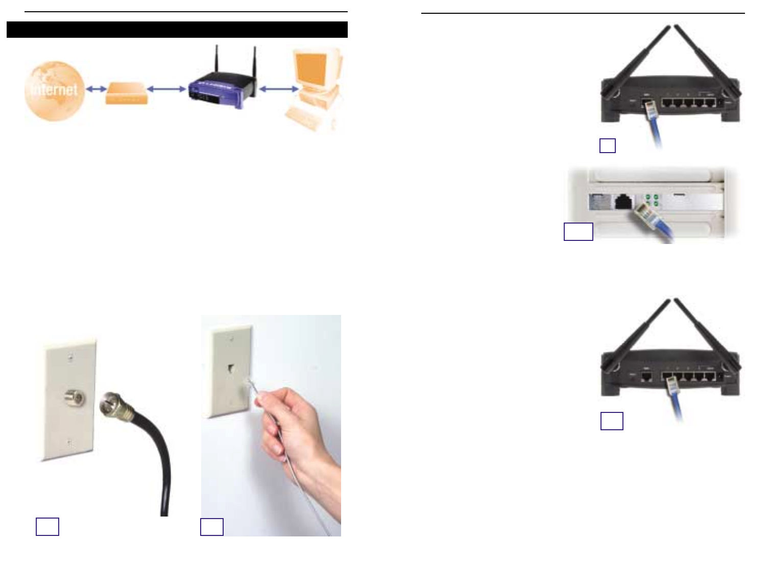
147146
En el Paso 1, conectará el ruteador al módem por cable o DSL y a los equipos de su casa u
oficina.
Compruebe que todos los dispositivos que va a utilizar están apagados,incluidos los PC, el
módem y el ruteador.
A. Conecte el módem por cable o DSL a su toma correspondiente: la toma coaxial para el
módem por cable (Figura A1) o la toma de teléfono para el módem DSL (Figura A2). (Siga
las instrucciones del manual de instalación de los módems.)
Instant Wireless™ Series
B. Con un cable Ethernet, conecte el puerto
LAN o Ethernet del módem por cable o DSL
al puerto WAN del ruteador.
C. Conecte un cable Ethernet al
adaptador Ethernet del PC.
Conecte el otro extremo del cable
a uno de los puertos LAN del
ruteador. Repita este proceso con
cada PC que desee conectar al
ruteador.
Nota: Si no está configurado el adaptador Ethernet del PC, consulte las instrucciones en
la documentación del adaptador Ethernet.
Para facilitar la instalación,utilice los puertos
LAN del ruteador en orden consecutivo de
menor a mayor, primero el 1, luego el 2 y así
sucesivamente.
Si va a conectar más de cuatro PC, deberá
conectar un hub o un switch al puerto Uplink
del ruteador (si utiliza el puerto Uplink,debe
dejar libre el Puerto 4). Para obtener más
información sobre cómo usar el puerto
Uplink, consulte el Manual del usuario del
CD-ROM del Asistente para instalación.
D. Conecte el cable de alimentación a la toma
de corriente del ruteador. A continuación, conecte el enchufe a una toma de corriente.
Encienda el módem por cable o DSL y el primer PC que va a configurar en el ruteador.
Continúe con el Paso 2: Configuración de los PC en la página siguiente.
Ruteador Access Point para conexiones inalámbricas con switch de 4 puertos
A1A2
Paso 1: Conexión del ruteador
B
C1
C2
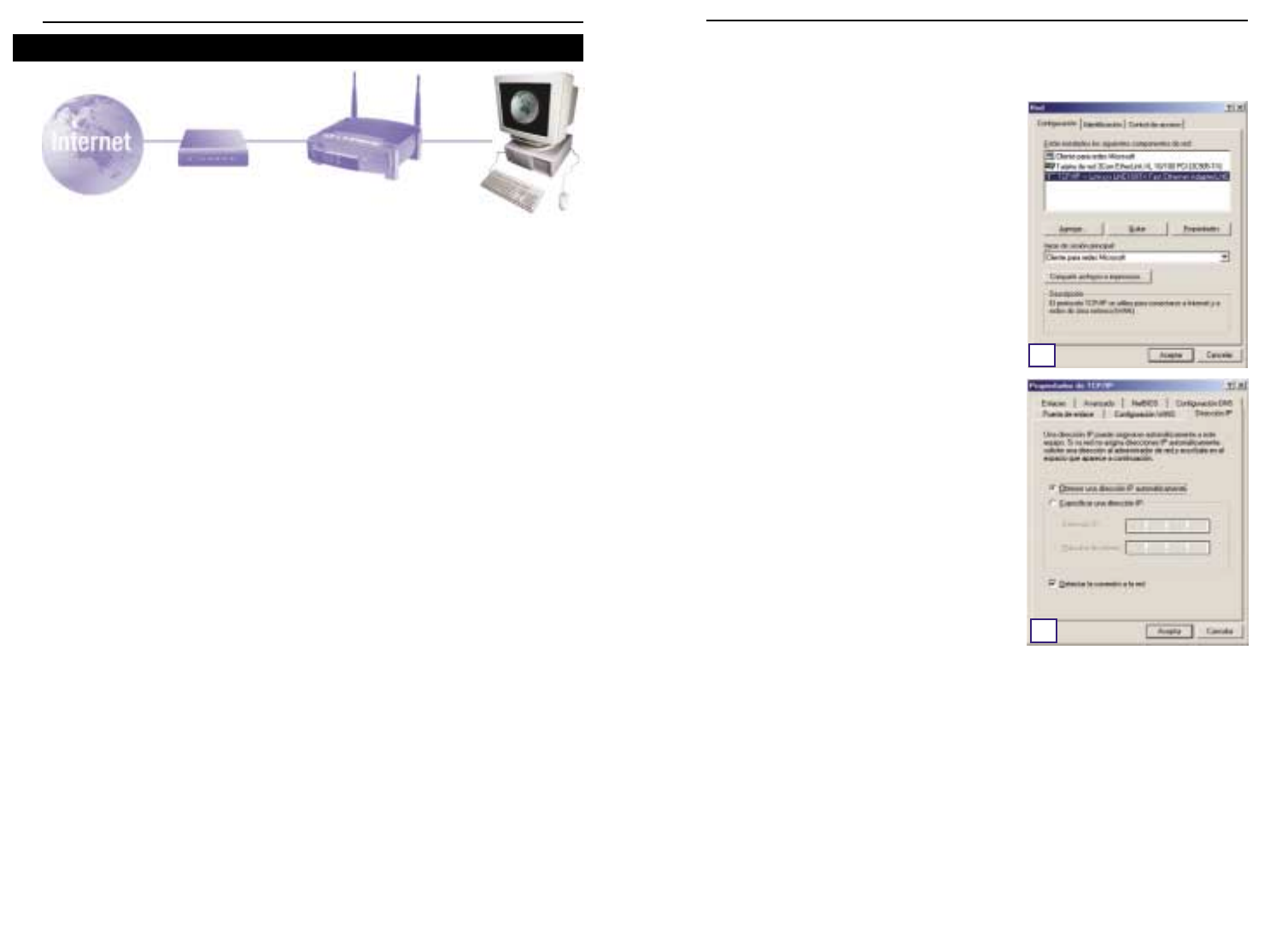
149148
En el Paso 2, se configuran los PC para su comunicación con el ruteador.
Para ello, deberá configurar los parámetros de la red de PC de forma que obtengan las
direcciones IP (o TCP/IP) automáticamente. Los equipos utilizan las direcciones IP para
comunicarse entre sí a través de una red o de Internet.
Averigüe qué sistema operativo utiliza su equipo, por ejemplo,Windows 95, 98,Millennium,
2000 o XP. Esta comprobación es necesaria. Puede averiguarlo haciendo clic en el botón
Inicio y eligiendo la opción Configuración. (Si en el menú Inicio no aparece la opción
Configuración, está utilizando Windows XP. Puede abrir el Panel de control directamente
desde el menú Inicio.) A continuación, haga clic en Panel de control y haga doble clic en
el icono Sistema. Cuando termine,haga clic en el botón Cancelar.
Después de comprobar la versión del sistema operativo Windows,siga las instrucciones de
este paso para el sistema que corresponda a su equipo. Si es preciso, repita estos pasos
para cada equipo que vaya a conectar al ruteador.
En las páginas siguientes se describe paso a paso cómo configurar los parámetros TCP/IP
para los distintos tipos de sistemas operativos Windows. Después de configurar los
equipos, vaya al Paso 3: Configuración del ruteador.
A. Haga clic en el botón Inicio, elija
Configuración y abra el Panel de control. En
el Panel de control, haga doble clic en el icono
Red para abrir el cuadro de diálogo Red.
B. En la ficha Configuración, seleccione la línea
TCP/IP del adaptador Ethernet correspondien-
te*. Si aparece únicamente TCP/IP,seleccione
esta línea**. A continuación, haga clic en el
botón Propiedades.
C. Haga clic en la ficha Dirección IP y seleccione
Obtener una dirección IP automáticamente.
D. Haga clic en la ficha Puerta de enlace y com-
pruebe que el campo Puertas de enlace insta-
ladas está vacío. Haga clic en el botón
Aceptar.
E. Vuelva a hacer clic en el botón Aceptar. Es
posible que Windows le pida el disco de insta-
lación original u otros archivos adicionales.
Cuando se le pida,indique la ubicación correc-
ta de los archivos, p. ej., D:\win98, D:\win9x,
c:\windows\options\cabs, etc. (Se presupone
que “D” es la letra correspondiente a la unidad de CD-ROM).
FSi Windows solicita que reinicie el equipo, haga clic en el botón Sí. Reinicie el equipo
de todas formas aunque el programa no lo pida.
*Nota: no seleccione las líneas TCP/IP donde se indique DUN, PPPoE,VPN o AOL.
**Nota: si no aparece TCP/IP en ninguna línea, consulte el Manual del usuario del CD-ROM
del Asistente para instalación de la documentación del adaptador Ethernet e instale el
protocolo TCP/IP.
Instant Wireless™ Series Ruteador Access Point para conexiones inalámbricas con switch de 4 puertos
Paso 2: Configuración de los PC Para los sistemas operativos:
Windows 95, Windows 98 y Windows Me
B
C
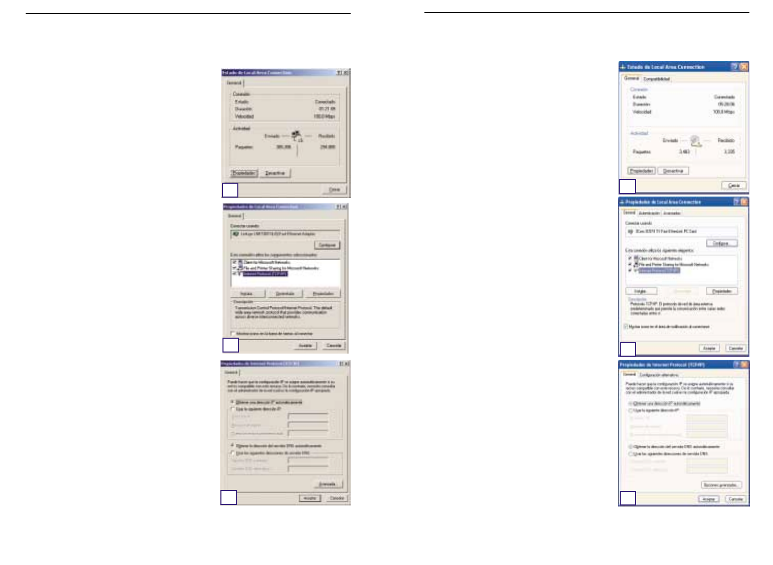
151150
Las siguientes instrucciones se refieren únicamente
a la interfaz predeterminada de Windows XP. Si uti-
liza la interfaz Clásica (que muestra los iconos y los
menús parecidos a las versiones anteriores de
Windows), siga las instrucciones para Windows
2000.
A. Haga clic en el botón Inicio, abra el Panel de
control y haga clic en el icono Conexiones de
red e Internet. A continuación, haga clic en el
icono Conexiones de red para abrir la pantalla
Red.
B. Seleccione el icono Conexión de área local
correspondiente a su adaptador Ethernet (normal-
mente, la primera conexión de área local de la
lista). Haga doble clic en Conexión de área
local.
C. En la pantalla de estado que aparece, haga clic
en el botón Propiedades.
D. Seleccione Protocolo de Internet (TCP/IP) y
haga clic en el botón Propiedades.
E. Seleccione Obtener una dirección IP
automáticamente y haga clic en el botón
Aceptar de las siguientes pantallas hasta com-
pletar la configuración del PC.
FReinicie el equipo.
A. Haga clic en el botón Inicio,elija Configuración
y abra el Panel de control. En el Panel de con-
trol, haga doble clic en el icono Conexiones de
red y de acceso telefónico. Se abre el cuadro
de diálogo Red.
B. Seleccione el icono Conexión de área local
correspondiente a su adaptador Ethernet* (nor-
malmente, la primera conexión de área local de
la lista). Haga doble clic en Conexión de área
local.
C. En la pantalla de estado que aparece, haga clic
en el botón Propiedades.
D. Seleccione Protocolo de Internet (TCP/IP) y
haga clic en el botón Propiedades.
E. Seleccione Obtener una dirección IP
automáticamente y haga clic en el botón
Aceptar de las siguientes pantallas hasta com-
pletar la configuración del PC.
FReinicie el equipo.
*Nota: no seleccione las líneas TCP/IP donde se
indique DUN,PPPoE,VPN o AOL.
Instant Wireless™ Series Ruteador Access Point para conexiones inalámbricas con switch de 4 puertos
Para el sistema operativo:
Windows 2000
E
D
C
Para el sistema operativo:
Windows XP
C
D
E
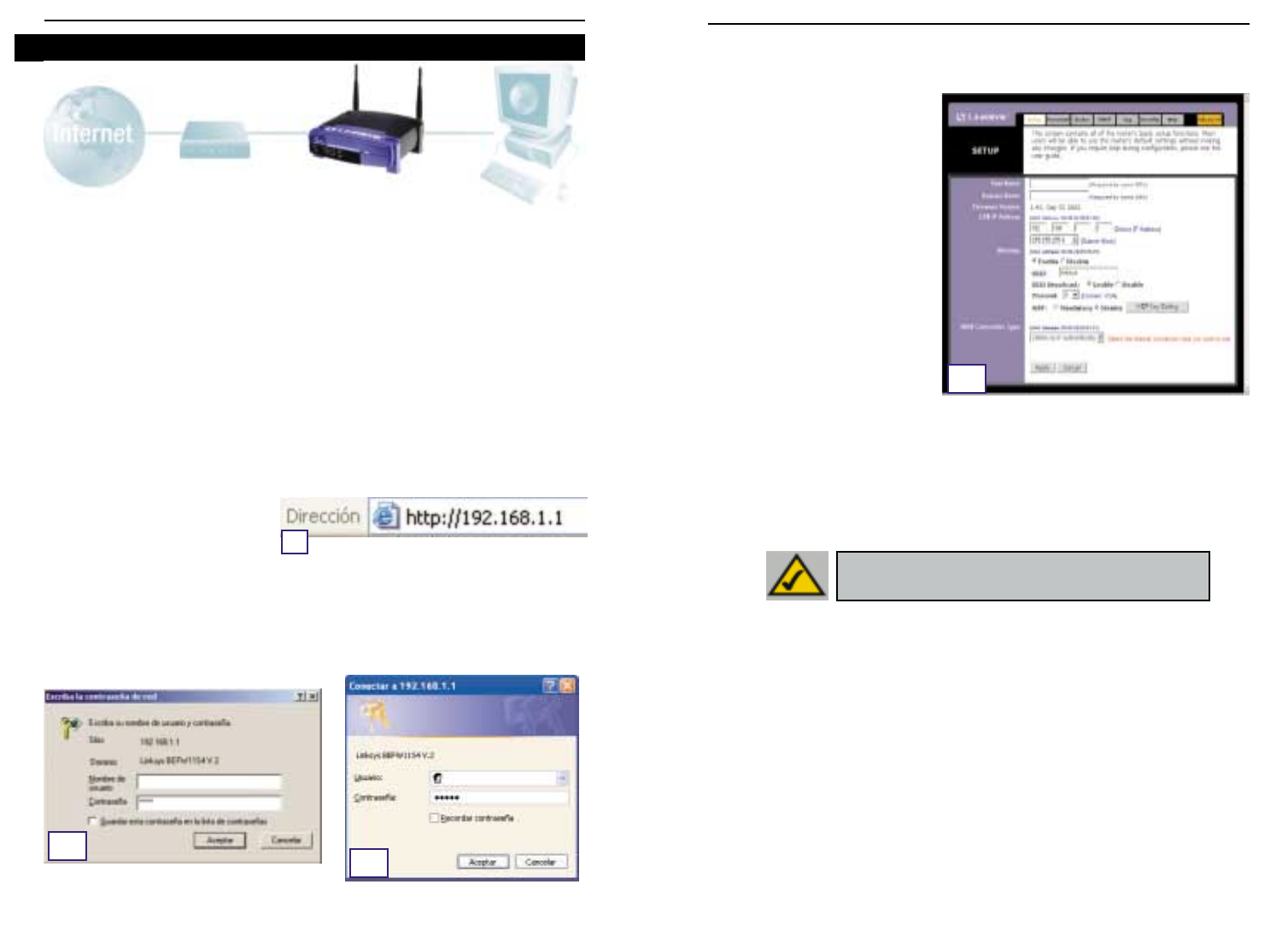
153152
C. Si su ISP lo requiere,escriba el Nombre de host y el Nombre de dominio del ruteador
en los campos correspondientes de la ficha de configuración. (Normalmente, estos
datos son necesarios para los ISP de conexión por cable.)
D. Para configurar el ruteador para
una red inalámbrica, compruebe
que los campos Wireless
(Inalámbrico) de la ficha Setup
(Configuración), que muestra la
Figura D, se han completado
como sigue:
Enable/Disable
(Activar/desactivar): Al selec-
cionar el botón de opción Enable
(Activar) se activan las fun-
ciones inalámbricas del
ruteador. Estas funciones no
estarán disponibles si no se
selecciona este botón.
SSID: SSID (o ESSID) es un nombre exclusivo para la red inalámbrica. El nombre dis-
tingue entre mayúsculas y minúsculas y no debe superar los 32 caracteres. El SSID pre-
determinado es “linksys “, pero se recomienda cambiarlo por un nombre más descrip-
tivo de la red inalámbrica. Todos los puntos de la red inalámbrica deben utilizar el
mismo SSID.
Channel (Canal): Seleccione en la lista el canal apropiado de la red. Todos los puntos
de la red inalámbrica deben usar el mismo canal para funcionar correctamente.
E. El ruteador admite cinco tipos de conexiones: DHCP (obtener una dirección IP automáti-
camente), PPPoE, Dirección IP estática, RAS y PPTP. Estos tipos se seleccionan en el
menú desplegable que aparece junto a WAN Connection Type (Tipo de conexión WAN).
La pantalla de configuración y las distintas características varían según el tipo de
conexión seleccionado. Vea las instrucciones a continuación:
1. Obtener una dirección IP automáticamente
Si el ISP le indica que su conexión es a través de una dirección IP dinámica (o DHCP), siga
estos pasos:
a. Seleccione Obtener una dirección IP automáticamente en el Tipo de conexión WAN
(como se muestra en la Figura D).
b. Haga clic en el botón Apply (Aplicar) para guardar la configuración.
En el Paso 3,configurará el ruteador para su funcionamiento en la red y para obtener acce-
so a Internet mediante un Proveedor de servicios de Internet (ISP). Es posible que su ISP le
pida que utilice un Nombre de host y un Nombre de dominio. A continuación,definirá el tipo
de configuración WAN en la ficha de configuración de ruteador con los datos obtenidos de
su ISP.
Estos datos son necesarios.
Si no los tiene, consulte a su ISP antes de continuar. Para
saber qué datos necesita obtener de su ISP, consulte la pregunta nº 1 de la Ayuda.
El ISP le proporcionará las instrucciones para configurar el acceso a Internet desde su PC.
Puesto que se va a utilizar para compartir el acceso a Internet entre varios equipos, tam-
bién deberá utilizar esta información para la configuración del ruteador.
A. Abra el navegador Web. (Es posible que aparezca algún mensaje de error en este
momento. Continúe con las siguientes instrucciones) Escriba 192.168.1.1 en el campo
Dirección del navegador y pulse la tecla Entrar.
B. Aparece el cuadro de diálogo Escribir contraseña de red, como muestra la Figura B1.
(Los usuarios de Windows XP verán la ventana Conectar con 192.168.1.1, que muestra
la Figura B2.) Deje vacío el campo Nombre de usuario y escriba en minúsculas admin
(la contraseña predeterminada) en el campo Contraseña. A continuación, haga clic en
el botón Aceptar.
Instant Wireless™ Series Ruteador Access Point para conexiones inalámbricas con switch de 4 puertos
Paso 3: Configuración del ruteador
A
B1B2
D
NNoottaa:: Si desea modificar la configuración WEP del ruteador,
elija Configuración de la seguridad inalámbrica.

155154
Ruteador Access Point para conexiones inalámbricas con conmutador de 4 puertos
Instant Wireless™ Series
2. Static IP (IP estática)
Si el ISP le indica que su conexión es a
través de una dirección IP estática (o
fija), siga estos pasos:
a. Seleccione Static IP en WAN
Connection Type (Tipo de conexión
WAN) .
b. En los campos que aparecen junto
a “Specify WAN IP Address”,
escriba la Dirección IP.
c. Escriba la Máscara de subred.
d. Escriba la Dirección de la puerta
de enlace predeterminada.
e. Escriba el DNS en los campos 1, 2
y 3. Debe indicar al menos una
dirección de servidor DNS.
f.
Haga clic en
el botón
Apply (Aplicar) para guardar la configuración.
3. PPPoE
Si su proveedor de DSL le indica que
utiliza una conexión PPPoE, o si
escribe normalmente un nombre de
usuario y una contraseña para conec-
tarse a Internet, siga estos pasos:
a. Seleccione PPPoE como Tipo de
conexión Wan (WANConnection
Type).
b. Escriba el Nombre de usuario.
c. Escriba la Contraseña.
d. Haga clic en el botón Apply
(Aplicar)para guardar la configu-
ración.
e. Haga clic en la ficha Status (Estado) y, a continuación, en el botón Connect (Conectar)
para iniciar la conexión.
E2
E3
4. RAS
El servicio RAS se utiliza únicamente en Singapur. Si utiliza una conexión RAS,
solicite a su ISP los datos necesarios para la configuración.
5. PPTP
El servicio PPTP se utiliza única-
mente en Europa. Si utiliza una
conexión PPTP, solicite a su ISP
los datos necesarios para la con-
figuración.
FHaga clic en el botón Apply (Aplicar) para guardar la configuración.
G. Conecte el módem por cable o DSL y reinicie los equipos. Se cargan los nuevos
valores del ruteador.
Nota: sólo necesita configurar el ruteador para un equipo. Si desea consultar
la información avanzada,visite el sitio Web de asistencia técnica de Linksys en
la dirección
support.linksys.com
o vea el Manual del usuario en el CD-ROM del
Asistente para instalación.
Ha completado la configuración del ruteador. Para probar su funcionamiento,
abra el navegador Web en cualquier equipo y escriba
www.linksys.com/registration
.
Si no puede abrir nuestra página Web, vuelva a comprobar los pasos que ha
realizado anteriormente o consulte la sección de ayuda de este manual.
E5

157156
2. Tengo problemas para conectar a Internet. ¿Que indicadores tienen que
estar encendidos en la parte frontal del ruteador?
•Por cada equipo conectado correctamente en la parte posterior del ruteador
deberá encenderse un indicador, independientemente de si se utiliza un cable
Ethernet o uno de alimentación.
Por ejemplo,normalmente,al conectar un equipo y un módem por cable o DSL
se encienden los siguientes indicadores:
- Al encender el ruteador (el adaptador de alimentación conectado al
ruteador), se enciende el indicador
Power
.
- Al conectar correctamente un cable Ethernet a un PC y al Puerto 4 del
ruteador, se encienden los indicadores
Link/Act
,
Ful/Col
y
100
de la
Columna 4.
- Al conectar un módem por cable o DSL, se enciende el indicador
WAN
Link
.
Instant Wireless™ Series
En la sección de ayuda puede encontrar las preguntas más frecuentes sobre la conexión a
Internet. Si necesita más información sobre la configuración o sobre las funciones avan-
zadas, visite
kb.linksys.com
o consulte el apéndice de solución de problemas en el Manual
del usuario del CD-ROM del Asistente para instalación.
1. No conozco los datos que debo obtener del Proveedor de servicios de Internet
(ISP) para poner la red en funcionamiento. ¿Qué preguntas tengo que hacer?
Cuál es el tipo de conexión: dirección IP dinámica, dirección IP estática o PPPoE
•Si utiliza una dirección IP dinámica, deberá averiguar:
- El nombre del host (si procede)
- El nombre de dominio (si procede)
•Si utiliza una dirección IP estática, deberá averiguar:
- La dirección IP
- La pasarela
- El DNS
•Si utiliza PPPoE (lo utilizan normalmente los ISP de DSL), deberá averiguar:
- El nombre de usuario
- La contraseña
Cuando tenga la información, siga las instrucciones del apartado Inicio rápido - Paso 3:
Configuración del ruteador. Utilice esta información para rellenar la ficha Setup
(Configuración) al configurar el ruteador. Para la sección WAN Connection Type (Tipo de
conexión WAN) consulte el gráfico de la página siguiente:
Ayuda ?Dirección IP
dinámica (DHCP) 1. Seleccione Obtener una dirección IP automáticamente en
el Tipo de conexión WAN .
2. Haga clic en el botón Apply (Aplicar) para guardar la configu-
ración.
Siga estos pasos:
PPPoE 1. Seleccione PPPoE en el Tipo de conexión WAN .
2. Escriba el Nombre de usuario.
3. Escriba la Contraseña.
4. Haga clic en el botón Apply (Aplicar) para guardar la configu-
ración.
Dirección IP
estática 1.
Seleccione Static IP (IP estática) en el Tipo de conexión WAN.
2. Escriba la Dirección IP.
3. Escriba la Máscara de subred.
4. Escriba la Dirección de la puerta de enlace.
5. Escriba el DNS en los campos 1, 2 y 3. Debe indicar al menos
una dirección DNS.
6. Haga clic en el botón Apply (Aplicar) para guardar la configu-
ración.
RAS o PPTP Si utiliza RAS (SingTel de Singapur) o PPTP (servicio para Europa),
consulte a su ISP los datos necesarios para la instalación.
Si tiene este tipo de
conexión:
Ruteador Access Point para conexiones inalámbricas con conmutador de 4 puertos

159158
Ruteador Access Point para conexiones inalámbricas con conmutador de 4 puertos
•En el campo Dirección IP deberán aparecer las direcciones IP 192.168.1.100 o
192.168.1.xxx, donde “xxx”es un número mayor de 100. Si su dirección IP no se
encuentra dentro de este rango, mantenga pulsado el botón Reset de la parte
frontal del ruteador durante más de 30 segundos. Esta operación restablece los
valores predeterminados de fábrica del ruteador, por lo que deberá volver a com-
pletar la página de configuración del ruteador. Después de configurar la página,
reinicie el equipo.
C. A continuación, configurará algunos parámetros en Windows.
- Haga doble clic en el icono Mi PC del Escritorio y, a continuación, haga doble clic en
Panel de control (Si utiliza Windows XP y la interfaz predeterminada, haga clic en
Inicio y elija Panel de control).
- En el Panel de control, haga doble clic en el icono Opciones de Internet (Si utiliza
Windows XP y la interfaz predeterminada, haga clic en Conexiones de red e Internet
y, a continuación, haga clic en Opciones de Internet).
- En el cuadro de diálogo Opciones de Internet, haga clic en la ficha Conexiones.
- Active la casilla de selección No marcar nunca una conexión. (Si la opción aparece
difuminada, no es necesario activarla.)
- Haga clic en el botón Configuración LAN… de la esquina inferior derecha.
- En el cuadro de diálogo Configuración de red de área local (LAN) que aparece, desactive
todas las casillas de selección.
- Haga clic en los botones Aceptar y Aplicar (el botón Aplicar aparece atenuado si no
se han hecho cambios). A continuación, vuelva a hacer clic en el botón Aceptar.
- Cierre el Panel de control y reinicie el equipo.
4. Al hacer clic en el icono de acceso a Internet y escribir el nombre de usuario y
la contraseña proporcionados por mi ISP, no puedo conectar a Internet. ¿Cuál es
el error?
Posiblemente, está utilizando el software que le ha proporcionado su ISP. Utilice Internet
Explorer o Netscape Navigator, que puede encontrar en el Escritorio (en Windows XP, se
encuentran en el menú Inicio).
5. Al abrir Internet Explorer, aparece un cuadro de diálogo de conexión de Acceso
telefónico a redes. ¿Cómo se desactiva?
A. Haga doble clic en el icono Mi PC del Escritorio y, a continuación, haga doble clic en
Panel de control (Si utiliza Windows XP y la interfaz predeterminada, haga clic en
Inicio y elija Panel de control).
B. En el Panel de control, haga doble clic en el icono Opciones de Internet (Si utiliza
Windows XP y la interfaz predeterminada, haga clic en Conexiones de red e Internet
y, a continuación, haga clic en Opciones de Internet).
C. En el cuadro de diálogo Opciones de Internet, haga clic en la ficha Conexiones.
Instant Wireless™ Series
•No se enciende el indicador
WAN Link
. ¿Qué debo comprobar?
- Compruebe si el cable conectado al módem por cable o DSL y el ruteador es el
mismo que venía con el módem. Dependiendo del tipo de conexión del módem,
necesitará un cable Ethernet “recto” o “cruzado” (el cable “recto” es el más
habitual).
•Algunos indicadores de la parte frontal del ruteador no se encienden al conectar un PC.
- Para que la conexión funcione correctamente sólo es necesario que se encienda
el indicador
Link/Act
.
3. No puedo entrar en Internet ni acceder a la página de configuración del ruteador.
¿Qué debo comprobar?
A. En primer lugar, compruebe que el módem por cable o DSL y los equipos están conec-
tados correctamente. Para verificar si el estado de las conexiones es correcto,consulte
la Pregunta nº 2.
B. A continuación, compruebe si los PC están configurados correctamente para comuni-
carse con el ruteador. A continuación se describen las instrucciones para las distintas
versiones de Windows.
-Windows 95, 98 o ME
•Haga clic en el menú Inicio y elija Ejecutar. En el cuadro de diálogo Ejecutar,
escriba winipcfg en el campo Abrir y haga clic en el botón Aceptar.
•En el cuadro de diálogo Configuración IP, haga clic en el cuadro gris con la
flecha hacia abajo.
•Se abre una lista de adaptadores. Seleccione el adaptador que utiliza para
conectarse a Internet. En los adaptadores no debe aparecer “PPP”, “VPN”,
“AOL” ni “Adaptador de Acceso telefónico a redes”.
•En el campo Dirección IP deberán aparecer las direcciones IP 192.168.1.100 o
192.168.1.xxx, donde “xxx”es un número mayor de 100. Si su dirección IP no
se encuentra dentro de este rango, mantenga pulsado el botón Reset de la
parte frontal del ruteador durante más de 30 segundos. Esta operación
restablece los valores predeterminados de fábrica del ruteador, por lo que
deberá volver a completar la página de configuración del ruteador. Después de
configurar la página, reinicie el equipo.
-Windows NT, 2000 y XP
•Haga clic en el menú Inicio y elija Ejecutar. En el cuadro de diálogo Ejecutar,
escriba cmd en el campo Abrir y haga clic en el botón Aceptar.
•Se abre la ventana de la línea de comandos. Escriba ipconfig /all y pulse la
tecla Entrar.
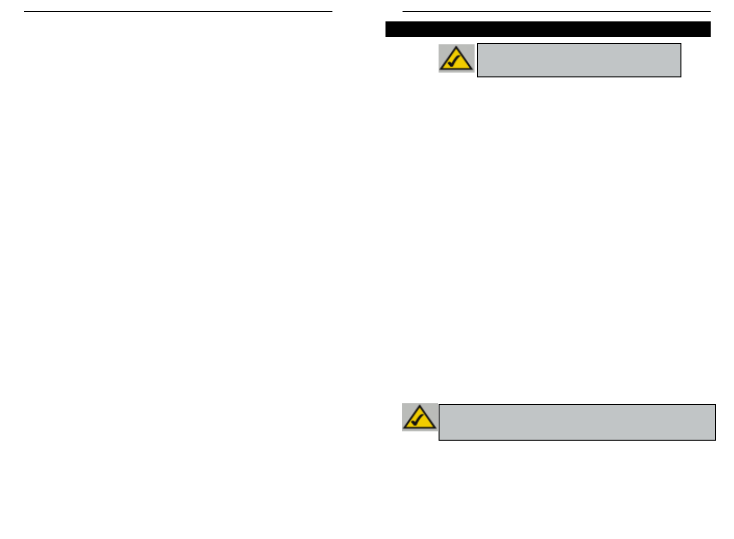
161160
Ruteador Access Point para conexiones inalámbricas con conmutador de 4 puertos
Instant Wireless™ Series
D. Active la casilla de selección No marcar nunca una conexión.
E. Haga clic en el botón Aplicar.
F. Haga clic en el botón Aceptar.
6. No aparece la señal de potencia de calidad de conexión. ¿Qué puedo hacer?
A. Compruebe si el indicador WLAN LED del ruteador está encendido.
B. Asegúrese de que todos los PC inalámbricos utilizan el modo “Infraestructura”.
7. ¿Cómo se amplía el alcance del ruteador?
A. El ruteador debe estar colocado en el lugar más alto posible.
B. No debe colocarse junto a equipos que produzcan muchas interferencias. (Por ejemplo:
altavoces, tubos fluorescentes, microondas, etc.)
C. Cambie el canal inalámbrico. Para hacerlo:
- Abra el navegador Web y escriba http://192.168.1.1 en el campo “Dirección”.
- En el cuadro “Escribir contraseña de red”, deje vacío el campo “Nombre de usuario” y
escriba admin en el campo de contraseña. A continuación,haga clic en Aceptar.
- En la ficha Configuración, cambie el canal a 1.
- Haga clic en le botón Aplicar y Continuar para guardar la configuración.
- Repita estos pasos hasta encontrar el canal que proporciona el mayor alcance.
Las siglas en inglés WEP (Wired Equivalent Privacy) significan Privacidad equivalente
al cableado, un sistema de protección de datos para las comunicaciones inalámbricas.
WEP emplea una combinación de claves de 64 o 128 bits para proporcionar control de
acceso a la red y seguridad encriptada para todas las transmisiones de datos. Para des-
encriptar una transmisión, todos los puntos de la red deben utilizar una clave idéntica de
64 o 128 bits. Cuanto más alto sea el nivel de encriptación, mayor será la seguridad,
aunque, debido a la complejidad de la encriptación, podría afectar negativamente al
rendimiento de la red.
Es posible que también haya oído la expresión “40 bits” relacionada con la encriptación
WEP. Se trata sencillamente de otro término utilizado para la encriptación WEP de 64
bits. Este nivel de encriptación WEP se denomina de 40 bits porque emplea una clave
secreta de 40 bits y un vector de iniciación de 24 bits (40 + 24 = 64). Los proveedores
de comunicaciones inalámbricas utilizan los dos nombres. Linksys usa la expresión “64
bits” para referirse a este nivel de encriptación.
Antes de empezar a configurar la encriptación WEP, compruebe que la red inalámbrica
funciona correctamente.
Una red inalámbrica con encriptación WEP de 128 bits NO puede comunicarse con otra
red que utilice la encriptación WEP de 64 bits. Por lo tanto, asegúrese de que todos los
dispositivos inalámbricos utilizan el mismo nivel de encriptación. Los dispositivos que
cumplen el estándar 802.11b son compatibles con la encriptación WEP de 64 bits.
Además de habilitar WEP, Linksys recomienda tomar las siguientes medidas de seguri-
dad:
•Cambiar el SSID predeterminado “linksys” por otro distinto
•Cambiar la clave WEP regularmente
Nota: La encriptación WEP es una medida de seguridad
de datos adicional no necesaria para el funcionamiento
del ruteador.
Nota: Para activar la encriptación WEP, debe activar antes las funciones
inalámbricas. Seleccione Enable (Activar) en la ficha Wireless (Inalámbricas)
del ruteador antes de continuar.
Configuración de la seguridad inalámbrica
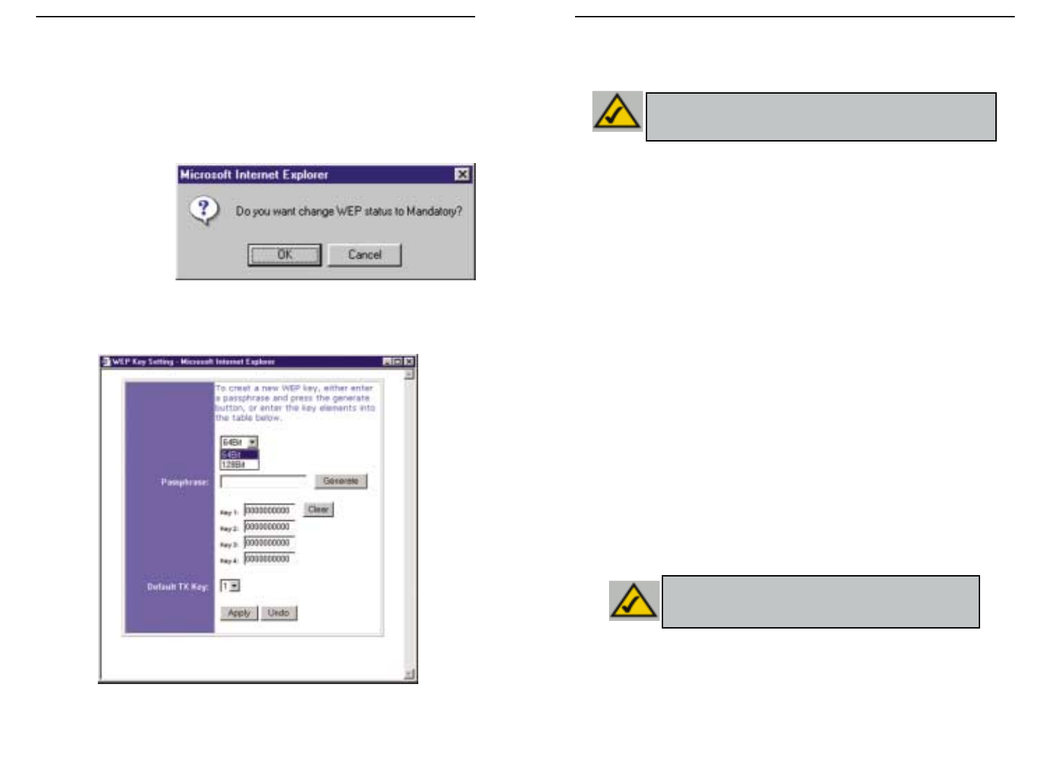
163162
Ruteador Access Point para conexiones inalámbricas con conmutador de 4 puertos
Instant Wireless™ Series
• WEP (64Bit o 128B) Seleccione el nivel de encriptación en la lista desplegable. La
encriptación WEP de 128 bits es exclusiva de Linksys y podría interferir con la
encriptación WEP de otros fabricantes.
La clave de encriptación WEP se genera de una de estas dos formas:
1. Puede crear una clave de encriptación mediante una Frase clave.
a. Escriba la Frase clave, una contraseña definida por el usuario, en el campo
Passphrase (Frase clave). La Frase clave no debe superar los 31 caracteres entre
letras, símbolos y números, y no se pueden utilizar espacios.
b. Haga clic en el botón Generate (Generar) para crear la clave. La clave será de
10 dígitos si elige la encriptación de 64 bits o de 26 dígitos si elige la
encriptación de 128 bits. Esta clave se utilizará para encriptar y desencriptar los
datos transferidos entre el ruteador y la red inalámbrica de PC.
Es posible que el campo Key (Clave) no muestre todos los dígitos. Haga clic en
cualquier parte del campo Key y mueva el cursor hacia la derecha para ver el
resto de la clave. Anote la clave completa EXACTAMENTE como aparece.
2. También puede introducir manualmente la clave de encriptación.
Anote la Frase clave o la Clave manual. Necesita conservarla ya que es necesario intro-
ducir la misma clave de encriptación WEP en todos los dispositivos inalámbricos de la
red.
Cuando haya elegido el método de encriptación de claves y especificado la Frase clave
o la clave manual, haga clic en el botón Apply (Aplicar) para completar la configu-
ración de la encriptación.
Nota: Para utilizar la encriptación WEP, todos los puntos de la red
inalámbrica deben tener activada la encriptación WEP y la misma
configuración de claves.
Nota: En Windows XP, una clave de 128 bits generada por el
ruteador se denomina clave de “104 bits (26 dígitos)” y una de
64 bits sería una clave de “40 bits (10 dígitos)” .
En los pasos siguientes se explica cómo utilizar la encriptación WEP
1. En la ficha Setup (Configuración) de la utilidad basada en Web, elija Mandatory
(Obligatorio) en la sección WEP.
2. Haga clic en el botón WEP Key Setting (Configuración de la clave WEP) para
definir el tipo y el nivel de encriptación WEP.
3. Es posible que aparez-
ca una pantalla
como la que muestra
la Figura C-1 solici-
tando que confirme
la activación de la
encriptación WEP.
Pulse el botón
Aceptar para conti-
nuar.
4. Se abre una pantalla como la que muestra la Figura C-2 en la que deberá seleccionar
los parámetros de la encriptación WEP.
Figura C-2
Figura C-1
165164
Ruteador Access Point para conexiones inalámbricas con conmutador de 4 puertos
Instant Wireless™ Series
2. En el “Panel de control”, haga clic en el icono Conexiones de red e Internet, como
muestra la Figura C-4.
3. Haga clic en el icono Conexiones de red, como muestra la Figura C-5.
4. Se abre el cuadro de diálogo “Conexiones de red”, como muestra la Figura C-6. En
LAN o Internet de alta velocidad se muestran todas las tarjetas de red instaladas y
en funcionamiento en su equipo. Haga doble clic en el icono Conexiones de red
inalámbricas asociado a su adaptador inalámbrico.
Si se abre un cuadro de diálogo de estado de la conexión inalámbrica, continúe en
el paso siguiente.
Figura C-4
Figura C-5
Puesto que Windows XP no permite utilizar la función de Frase clave de Linksys en los
adaptadores de PC inalámbricos, debe introducir manualmente la clave generada en el
apartado anterior.
En los pasos siguientes se explica cómo activar la encriptación WEP y escribir manual-
mente la clave de encriptación de las tarjetas de PC inalámbricos para que el sistema
Windows XP pueda comunicarse sin cables con el ruteador.
En estos pasos se presupone que la unidad de CD-ROM tiene asignada la letra D y que
se está ejecutando Windows XP en el modo predeterminado.
Compruebe si tiene la clave WEP generada por el ruteador.
1. Como muestra la Figura C-3, haga clic en el botón Inicio y abra el Panel de control.
Figura C-3
Configuración de la seguridad inalámbrica en Windows XP
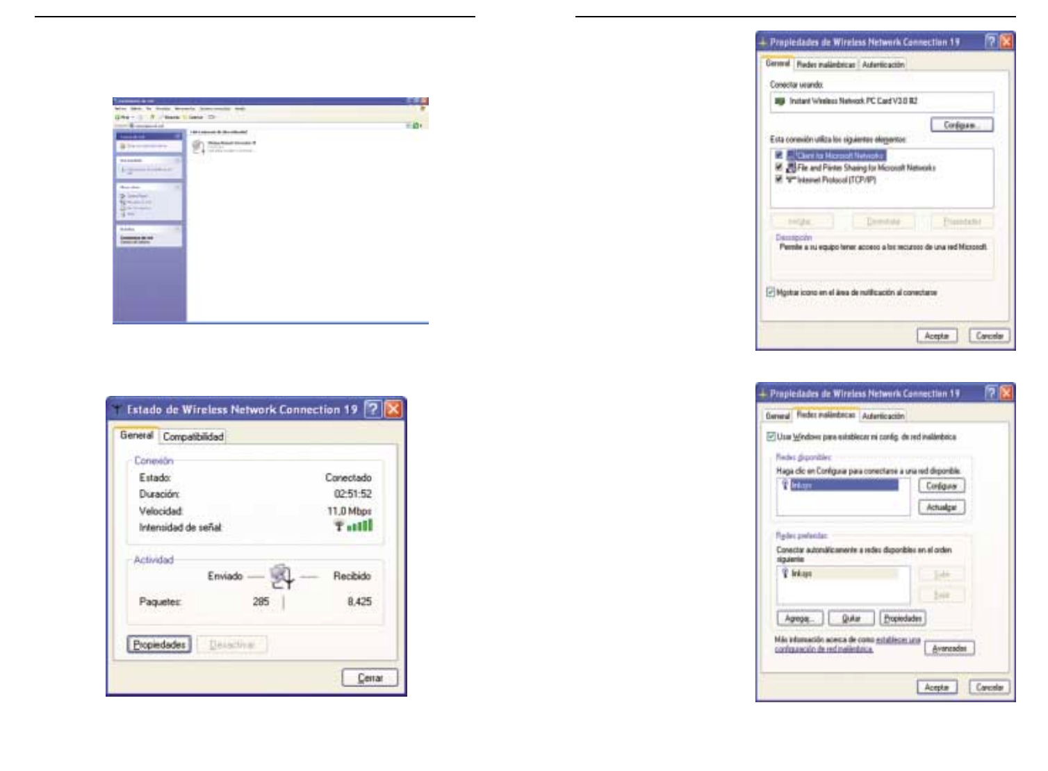
167166
Ruteador Access Point para conexiones inalámbricas con conmutador de 4 puertos
Instant Wireless™ Series
6. Cuando se abra el cuadro
de diálogo de propiedades
de la conexión inalámbrica
que muestra la Figura C-8,
haga clic en la ficha Redes
inalámbricas.
7. Si en la sección “Redes
preferidas” aparece la red
inalámbrica correcta que
indica el SSID del
ruteador, como muestra la
Figura C-9, haga doble clic
en ella y continúe en el
siguiente paso.
Si no aparece, en la sec-
ción “Redes disponibles”
haga clic en la red inalám-
brica que indica el SSID
del ruteador. A continua-
ción, haga clic en el botón
Configurar.
Figura C-8
Figura C-9
Si se abre el cuadro de diálogo “Conectar a red inalámbrica”, en la sección Redes
disponibles, haga clic en la red inalámbrica que va a utilizar y que aparece marcada
con el SSID de ruteador. A continuación, haga doble clic en el icono Conexiones de
red inalámbricas.
5. Cuando se abra el cuadro de diálogo de estado de la conexión inalámbrica que
muestra la Figura C-7, haga clic en el botón Propiedades.
Figura C-6
Figura C-7
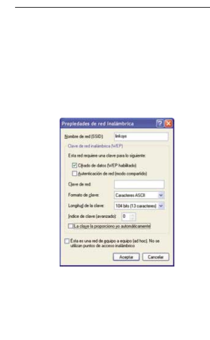
168
Instant Wireless™ Series
8. Se abre el cuadro de diálogo de propiedades de la red inalámbrica, como muestra la
Figura C-10.
Active la casilla de selección de la opción Encriptación de datos (WEP habilita-
do).
Desactive las casillas de selección de los campos Autenticación de red (modo
compartido) y La clave la proporciono yo automáticamente.
En el campo “Clave de red”, escriba la clave exacta (los 10 o 26 dígitos, según el
nivel de encriptación) generada por el ruteador.
Compruebe que el campo “Formato de clave” muestra “Dígitos hexadecimales” y
que el campo “Longitud de la clave” muestra “40 bits (10 dígitos)” o “104 bits (26
dígitos)”. Si no aparecen estos datos, la clave que ha escrito no es correcta.
Haga clic en el botón Aceptar para guardar la configuración. Haga clic en los
botones Aceptar restantes hasta que regrese al cuadro de diálogo de estado de la
conexión de red inalámbrica. Cierre los cuadros de diálogo abiertos para regresar al
Escritorio de Windows XP.
Cierre todas las aplicaciones y reinicie el equipo. Cuando vuelva a arrancar, la configu-
ración de WEP estará completa y podrá conectarse sin cables al ruteador.
Figura C-10

© Copyright 2002 Linksys, All Rights Reserved.
Printed in the USA.
www.linksys.com
Instant Wireless™ Series
Wireless Access Point Router
with 4-Port Switch
Use this Guide to install: BEFW11S4
User Guide

COPYRIGHT & TRADEMARKS
Copyright © 2002 Linksys, All Rights Reserved. Instant Wireless is a trademark of
Linksys. Linksys and the Linksys logo are registered trademarks of Linksys Group, Inc.
Microsoft, Windows, and the Windows logo are registered trademarks of Microsoft
Corporation. All other trademarks and brand names are the property of their respective
proprietors.
FCC STATEMENT
The Instant Wireless™ Wireless Access Point Router with 4-Port Switch has been tested
and complies with the limits for a Class B digital device, pursuant to Part 15 of the FCC
Rules. These limits are designed to provide reasonable protection against harmful inter-
ference in a residential installation. This equipment generates, uses, and can radiate
radio frequency energy and, if not installed and used according to the instructions, may
cause harmful interference to radio communications. However, there is no guarantee that
interference will not occur in a particular installation. If this equipment does cause harm-
ful interference to radio or television reception, which is found by turning the equipment
off and on, the user is encouraged to try to correct the interference by one or more of the
following measures:
• Reorient or relocate the receiving antenna
• Increase the separation between the equipment or devices
• Connect the equipment to an outlet other than the receiver’s
• Consult a dealer or an experienced radio/TV technician for assistance
UG-BEFW11S4 v3-21009NC TE
EC DECLARATION OF CONFORMITY (EUROPE)
Linksys Group declares that the Instant Wireless™ Series products included in the Instant
Wireless™ Series conform to the specifications listed below, following the provisions of
the EMC Directive 89/336/EEC and Low Voltage Directive 73/23/EEC:
•ETS 300-826, 301 489-1 General EMC requirements for Radio equipment.
•EN 609 50 Safety
•ETS 300-328-2 Technical requirements for Radio equipment.
Note: This equipment is intended to be used in all EU and EFTA countries. Outdoor use
may be restricted to certain frequencies and/or may require a license for operation. For
more details, contact Linksys Corporate Compliance.
Note: Combinations of power levels and antennas resulting in a radiated power level of
above 100 mW are considered as not compliant with the above mentioned directive and
are not allowed for use within the European community and countries that have adopted
the European R&TTE directive 1999/5/EC and/or the CEPT recommendation Rec 70.03.
For more details on legal combinations of power levels and antennas, contact Linksys
Corporate Compliance.
•Linksys Group™ vakuuttaa täten että Instant Wireless IEEE 802.11 PC Card tyyppinen
laite on direktiivin 1999/5/EY, direktiivin 89/336/EEC ja direktiivin 73/23/EEC oleellis-
ten vaatimusten ja sitä koskevien näiden direktiivien muiden ehtojen mukainen.
•Linksys Group™ déclare que la carte PC Instant Wireless IEEE 802.11 est conforme
aux conditions essentielles et aux dispositions relatives à la directive 1999/5/EC, la
directive 89/336/EEC, et à la directive 73/23/EEC.
•Belgique B L’utilisation en extérieur est autorisé sur le canal 11 (2462 MHz), 12 (2467
MHz), et 13 (2472 MHz).
Dans le cas d’une utilisation privée, à l’extérieur d’un bâtiment, au-dessus d’un
espace public, aucun enregistrement n’est nécessaire pour une distance de moins
de 300m. Pour une distance supérieure à 300m un enregistrement auprès de l’IBPT
est requise. Pour une utilisation publique à l’extérieur de bâtiments, une licence de
l’IBPT est requise. Pour les enregistrements et licences, veuillez contacter l’IBPT.
•France F: Bande de fréquence restreinte: seuls les canaux 10, 11, 12, 13 (2457,
2462, 2467, et 2472 MHz respectivement) doivent être utilisés en France. Toute util-
isation, qu'elle soit intérieure ou extérieure, est soumise à autorisation. Vous pouvez
contacter l'Autorité de Régulation des Télécommuniations (http://www.art-telecom.fr)
pour la procédure à suivre.
•France F: Restricted frequency band: only channels 10, 11, 12, 13 (2457, 2462,
2467, and 2472 MHz respectively) may be used in France. License required for
every indoor and outdoor installations. Please contact ART for procedure to follow.
•Deutschland D: Anmeldung im Outdoor-Bereich notwending, aber nicht genehmi-
gungspflichtig. Bitte mit Händler die Vorgehensweise abstimmen.
•Germany D: License required for outdoor installations. Check with reseller for proce-
dure to follow.
•Italia I: E' necessaria la concessione ministeriale anche per l'uso interno. Verificare
con i rivenditori la procedura da seguire. L'uso per installazione in esterni non e' per-
messa.
•Italy I: License required for indoor use. Use with outdoor installations not allowed.
•the Netherlands NL License required for outdoor installations. Check with reseller for
procedure to follow.
•Nederlands NL Licentie verplicht voor gebruik met buitenantennes. Neem contact op
met verkoper voor juiste procedure.
For product support and product registration, contact us at the addresses below:
E-mail europe-support@linksys.com
latam-soporte@linksys.com
Web http://www.linksys.com/international

Instant WirelessTM Series
Table of Contents
Chapter 1: Introduction 1
The Linksys Wireless Access Point Router with 4-Port Switch 1
Features 1
Minimum Requirements 2
An Introduction to LANs and WANs 2
IP Addresses 3
The Wireless Access Point Router’s Ports 5
The Wireless Access Point Router’s LEDs 6
Chapter 2: Connecting the Router 8
Before You Start 8
Connecting Your Hardware Together & Booting Up 8
Chapter 3: Configuring the PCs 11
Overview 11
Configuring Windows 95, 98, and Millennium PCs 11
Configuring Windows 2000 PCs 13
Configuring Windows XP PCs 15
Chapter 4: Configuring the Router 17
Chapter 5: Using the Router’s Web-Based Utility 22
Setup 23
Password 27
Status 28
DHCP 30
Log 31
Security 33
Help 35
Advanced Tab: Filters 37
Advanced Tab: Port Range Forwarding 41
Advanced Tab: Dynamic Routing 46
Advanced Tab: Static Routing 47
Advanced Tab: DMZ Host 49
Advanced Tab: MAC Address Cloning 50
Advanced Tab: Wireless 51
Appendix A: Troubleshooting 54
Common Problems and Solutions 54
Frequently Asked Questions 67
Appendix B: How to Ping Your
ISP’s E-mail and Web Addresses 73
Appendix C: Configuring Wireless Security 76
Configuring Wireless Security in Windows XP 79
Appendix D: Finding the MAC Address
and IP Address for Your Ethernet Adapter 84
Appendix E: Setting Up AOL®
Broadband Cable & DSL 88
AOL Broadband via Cable 88
AOL Broadband via DSL 90
Appendix F: Glossary 91
Appendix G: Specifications 105
Environmental 106
Appendix H: Contact Information 107
Appendix I: Warranty Information 108
Wireless Access Point Router with 4-Port Switch

Wireless Access Point Router with 4-Port Switch
Chapter 1: Introduction
Congratulations on your purchase of a Wireless Access Point Router with 4-
Port Switch. The Wireless Access Point Router with 4-Port Switch provides the
ideal solution for connecting your wireless network to a high-speed broadband
Internet connection and a 10/100 Fast Ethernet backbone. Configurable as a
DHCP server for your existing network, the Wireless Access Point Router with
4-Port Switch acts as the only externally recognized Internet gateway on your
local area network (LAN) and serves as an Internet NAT firewall against
unwanted outside intruders. The Wireless Access Point Router with 4-Port
Switch can also be configured to filter internal users’ access to the Internet.
A typical router relies on a hub or a switch to share its Internet connection, but
the Linksys Wireless Access Point Router with 4-Port Switch channels this
connection through the blazing, full duplex speed of its built-in EtherFast®
10/100 4-Port Switch. This cutting-edge combination of wireless router and
switch technology eliminates the need to buy an additional hub or switch and
extends the range of your wireless network. Now your entire wireless network
can enjoy blazing broadband Internet connections supported by its robust
switched backbone. With the dual-function speed and power of the Wireless
Access Point Router with 4-Port Switch, your network will take off at speeds
faster than you ever imagined possible.
•Supports Universal Plug-and-Play for easy configuration
•Capable of up to 128-bit WEP Encryption
•Supports enhanced security using NAT firewall, ZoneAlarm Pro and PC-
cillin Software*
•Access your network remotely over the Internet through Virtual Private
Networking (VPN)
•Supports IPSec and PPTP Pass-Through
•Administer and upgrade the Router remotely over the Internet
•Configurable as a DHCP Server on your network
•Advanced security management functions for Port Filtering, MAC Address
Filtering, and DMZ Hosting
•Includes one Ethernet Cable to Connect to a Cable or DSL modem
*Full versions can be downloaded and/or purchased separately (Windows versions).
Support for PC-cillin and Zone Alarm Pro may be limited or not available outside of
United States and Canada.
2
Features
•One Windows 98 SE, Millennium, 2000, or XP PC equipped with:
•TCP/IP Protocol,
•Internet Explorer 4.0 or Netscape Navigator 4.7 for web-based
configuration,
•a CD-ROM Drive, and
•an Ethernet Adapter with a UTP CAT 5 Network Cable
•Cable or DSL Modem with Ethernet Connection and Internet Access
Simply put, a router is a network device that connects two networks together.
In this instance, the Router connects your Local Area Network (LAN), or the
group of PCs in your home or office, to the Wide Area Network (WAN) that is
the Internet. The Router processes and regulates the data that travels between
these two networks.
Think of the Router as a network device with two sides. The first side is made
up of your private Local Area Network (LAN) of PCs. The other, public side
is the Internet, or the Wide Area Network (WAN), outside of your home or
office.
The Router’s firewall (NAT) protects your network of PCs so users on the pub-
lic, Internet side cannot “see” your PCs. This is how your LAN, or network,
remains private. The Router protects your network by inspecting the first pack-
et coming in from the WAN port before delivery to the final destination on the
LAN port. The Router inspects Internet port services like the web server, ftp
server, or other Internet applications, and, if allowed, it will forward the packet
to the appropriate PC on the LAN side.
1
The Linksys Wireless Access Point Router with 4-Port Switch
Minimum Requirements
An Introduction to LANs and WANs
Instant WirelessTM Series

What’s an IP Address?
IP stands for Internet Protocol. Every device on an IP-based network, includ-
ing PCs, print servers, and routers, requires an IP address to identify its “loca-
tion,” or address, on the network. This applies to both the WAN and LAN con-
nections.
There are two ways of assigning an IP address to your network devices.
Static IP Addresses
A static IP address is a fixed IP address that you assign manually to a PC or
other device on the network. Since a static IP address remains valid until you
disable it, static IP addressing insures that the device assigned it will have that
same IP address until you change it. Static IP addresses are commonly used
with network devices such as server PCs or print servers.
If you use the Router to share your cable or DSL Internet connection, contact
your ISP to find out if they have assigned a static IP address to your account.
If so, you will need that static IP address when configuring the Router. You can
get the information from your ISP.
3
Dynamic IP Addresses
A dynamic IP address is automatically assigned to a device on the network,
such as PCs and print servers. These IP addresses are called “dynamic”
because they are only temporarily assigned to the PC or device. After a certain
time period, they expire and may change. If a PC logs on to the network (or the
Internet) and its dynamic IP address has expired, the DHCP server will assign
it a new dynamic IP address.
For DSL users, many ISPs may require you to log on with a user name and
password to gain access to the Internet. This is called “Point to Point Protocol
over Ethernet” or PPPoE. PPPoE is similar to a dial-up connection but does not
have a phone number to dial into, and PPPoE is a dedicated high-speed con-
nection. PPPoE also will provide the Router with a dynamic IP address to
establish a connection to the Internet.
DHCP (Dynamic Host Configuration Protocol) Servers
DHCP frees you from having to assign IP addresses manually every time a new
user is added to your network. PCs and other network devices using dynamic
IP addressing are assigned a new IP address by a DHCP server. The PC or net-
work device obtaining an IP address is called the DHCP client. The Router’s
WAN port is, by default, set as a DHCP client.
DHCP servers can either be a designated PC on the network or another network
device, such as the Router. By default, a DHCP server is enabled on your
Router’s LAN ports. If you already have a DHCP server running on your net-
work, you must disable one of the two DHCP servers. If you run more than one
DHCP server on your network, you will experience network errors, such as
conflicting IP addresses. To disable the Router’s DHCP function, see the
DHCP section in Chapter 3: Configuring the Router.
IP Addresses
Note: Since the Router is a device that connects two networks, it needs two
IP addresses—one for the LAN side, and one for the WAN side. In this User
Guide, you’ll see references to the “WAN IP address” and the “LAN IP
address.”
Since the Router has firewall security (NAT), only the Router’s WAN IP address
can be seen from the Internet.
However, even the WAN IP address can be blocked, so that the Router and
network seem invisible to the Internet—This is shown in the Filters section in
“Chapter 5: Using the Routers Web-Based Utility”.
Note: Even if you assign a static IP address to a PC, other PCs can still use
DHCP’s dynamic IP addressing, as long as the static IP is not within the
DHCP range of the LAN IP Address.
If the Router’s DHCP function fails to provide a dynamic IP address for any
reason, please refer to Appendix A: Troubleshooting.
Instant WirelessTM Series Wireless Access Point Router with 4-Port Switch
4
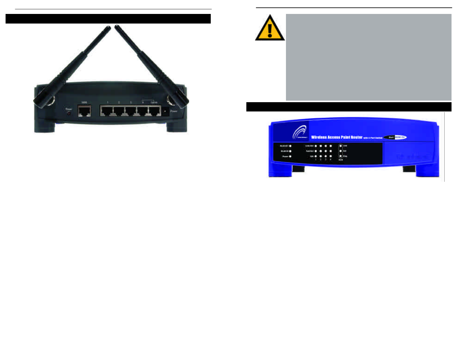
The LAN Indicators
WLAN Act Green. This LED indicates wireless activity.
WLAN Link Green. This LED indicates that the Router’s wireless func-
tions have been enabled through the Web-based utility.
Power Green. This LED indicates that the Router’s power is on.
Link/Act Green. This LED serves two purposes. When this LED is lit
continuously, this indicates that the Router is connected to a
device through the corresponding port (1, 2, 3, or 4). A blink-
ing LED indicates that the Router is actively sending or
receiving data over that port. When the Uplink Port is in use,
the LED for Port 4 will be lit continuously.
6
The Wireless Access Point Router’s LEDs
The Reset Button
Pressing the Reset Button and holding it in for a few seconds will clear all
of the Router’s data and restore the factory defaults. This should be done
only if you are experiencing heavy routing problems, and only after you
have exhausted all of the other troubleshooting options. By resetting the
Router, you run the risk of creating conflicts between your PCs’ actual IP
Addresses and what the Router thinks their IP Addresses should be. You
may be forced to reboot each network PC.
If the Router locks up, simply press the reset button or power it down for
three to five seconds by removing the power cable from the Router’s
Power Port. Leaving the power off for too long could result in the loss of
network connections.
Figure 1-2
The Router’s rear panel (as shown in Figure 1-1) is where all of its connections
are made.
WAN The WAN (Wide Area Network) Port is where you will con-
nect your cable or DSL modem with an Ethernet cable. Your
modem connection will not work from any other port.
Ports 1-4 These four LAN (Local Area Network) ports are where you
will connect networked devices, such as PCs, print servers,
and any other Ethernet devices you want to put on your net-
work. If Port 4 is being used, the Uplink Port will not work.
Uplink The Uplink Port is where you can expand your network by
connecting to another switch or hub. Uplinking to another
switch or a hub is done by simply running a cable from the
Uplink Port to the other device. The Uplink Port is shared
with Port 4. If the Uplink port is being used, Port 4 will not
work.
Power The Power Port is where you will connect the included AC
Power adapter.
Antenna Jacks The Antenna Jacks are where the included antennas are con-
nected.
Figure 1-1
The Wireless Access Point Router’s Ports
Instant WirelessTM Series Wireless Access Point Router with 4-Port Switch
5

Chapter 2: Connecting the Router
Before plugging everything together, it’s always a good idea to have everything
you’ll need to get the Router up and running. Depending upon how you config-
ure the Router in Chapter 4: Configuring the Router, you may need some of the
following values from your ISP:
When connecting through a Static IP connection, be sure to have 1) Your
broadband-configured PC’s fixed Internet IP Address, 2) Your broadband-
configured PC’s Computer Name and Workgroup Name, 3) Your Subnet
Mask, 4) Your Default Gateway, and 5) Your Primary DNS IP address.
When connecting through a PPPoE connection, be sure to have 1) Your
PPPoE User Name and 2) Your PPPoE Password.
The installation technician from your ISP should have left this information with
you after installing your broadband connection. If not, you can call your ISP to
request the data.
Once you have the above values, you can begin the Router’s installation and
setup.
Once you are sure that you have the above values on hand, you can begin the
Installation and Setup of the Router.
1. Power everything down, including your PCs, your cable or DSL modem and
the Router.
2. Connect an Ethernet cable from one of
your PC’s Ethernet ports to one of the
Router’s LAN ports (as shown in Figure 2-
1). Do the same with all the PCs you wish
to connect to the Router. (LAN Port 4 will
become inactive if you use the Uplink
port.)
In addition to accessing the Router through
an Ethernet connection, a wireless connec-
Before You Start
Full/Col Green. This LED also serves two purposes. When this LED
is lit continuously, the connection made through the corre-
sponding port is running in Full Duplex mode. A blinking
LED indicates that the connection is experiencing collisions.
Infrequent collisions are normal. If this LED blinks too
often, there may be a problem with your connection. Refer to
the Troubleshooting Appendix if you think there is a prob-
lem.
100 Orange. This LED indicates when a successful 100Mbps
connection is made through the corresponding port.
The WAN Indicators
Link Green. This LED indicates a connection between the Router
and your broadband device or network.
Act Green. This LED blinks when the Router is sending or
receiving data over the broadband (WAN) port.
Diag Red. This LED indicates the Router’s self-diagnosis mode
during boot-up and restart. It will turn off upon completing
the diagnosis. If this LED stays on for an abnormally long
period of time, refer to the Troubleshooting Appendix.
7
Connecting Your Hardware Together and Booting Up
Figure 2-1
Instant WirelessTM Series Wireless Access Point Router with 4-Port Switch
8
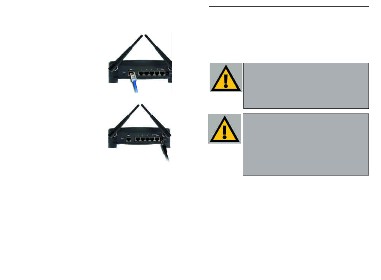
For Wireless Connections: In addition to accessing the Router through an
Ethernet connection, a wireless connection can be used to access the Router.
After powering on the Router and connecting it to your modem, enter the
Router’s IP Address in the Address field of your wireless PC’s web-browser as
follows: http://192.168.1.1 and press Enter.
Important: The Wireless Access Point Router with 4-Port Switch is
configured by default to work out of the box with all Linksys Wireless
Adapters. If you have changed the defaults on your Linksys Wireless
Adapters, or are using other wireless adapters, you must temporar-
ily change your wireless adapter settings to: (SSID = linksys) in
order to initially access the Router wirelessly. After you have
accessed the Router with the default settings, you can change the
router settings to coincide with your Network settings and reset your
adapters.
Important: Some ISPs—most notably some cable providers—config-
ure their networks so that you do not have to enter a full Internet
address into your web browser or e-mail application to reach your
home page or receive your e-mail. If your Internet home page
address is something very simple, such as “www”, rather than
“www.linksys.com”, or your e-mail server’s address is something sim-
ilar to “e-mail” or “pop3”, rather than “pop.mail.linksys.com”, you
won’t be able to properly configure the Router until you determine the
actual Internet addresses of your Web and e-mail connections.
You must obtain this information prior to connecting the Router to
your network. You can obtain this information by contacting your ISP.
10
tion can be used to access the Router. See the “For Wireless Connections”
section that follows these connection instructions.
3. Connect another Ethernet cable from your
cable or DSL modem to the Router’s WAN
port (as shown in Figure 2-2).
4. Connect the Power Adapter (included) to
the Router’s Power port (as shown in
Figure 2-3) and plug the other end into a
power outlet.
•The Power LED will illuminate green
as soon as the power adapter is con-
nected.
•The Diag LED will illuminate red for a
few seconds while the Router goes
through its internal diagnostic test. The
LED will turn off when the self-test is
complete.
5. Power on the cable or DSL modem. Verify
that the power is on by checking the Link LED in the WAN column on the
front of the Router. The Link LED will be illuminated if the power is on and
the modem is ready.
6. Press the Reset button on the back of the Router. Hold the button in for three
seconds, or until the Diag LED illuminates red. This restores the Router’s
default settings.
7. Power on your PC.
The Router is now connected. Continue to the next chapter to configure
your PCs.
Figure 2-2
Figure 2-3
Instant WirelessTM Series Wireless Access Point Router with 4-Port Switch
9
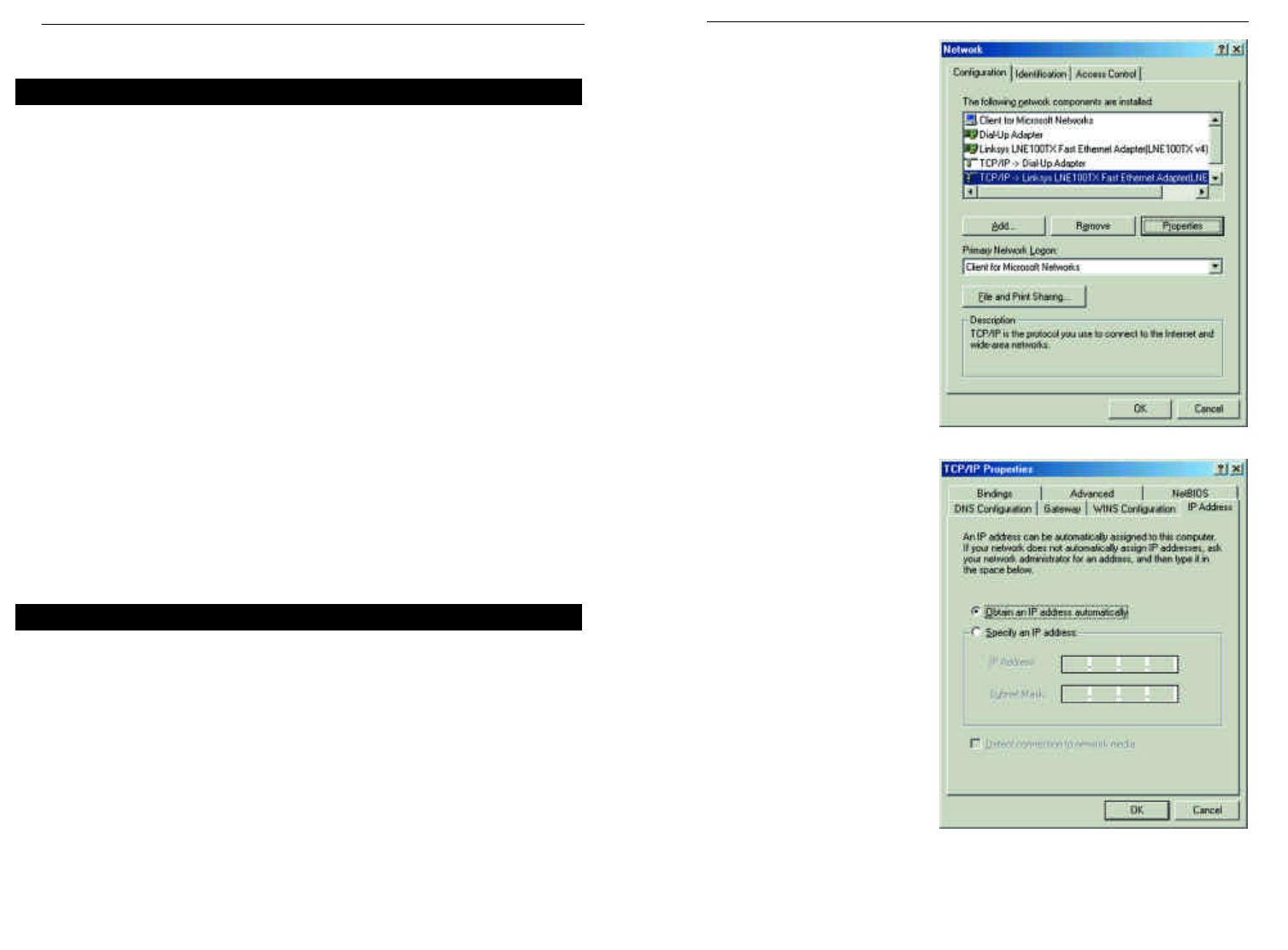
2. Select the Configuration tab
and highlight the TCP/IP
line for the applicable
Ethernet adapter (as shown
in Figure 3-1). If the word
TCP/IP appears by itself,
select that line. (Note: If
there is no TCP/IP line list-
ed, refer to your Ethernet
adapter’s documentation to
install TCP/IP now.) Then,
click the Properties button.
3. Click the IP Address tab
and select Obtain an IP
address automatically (as
shown in figure 3-2).
4. Click the Gateway tab and verify that the Installed Gateway field is blank.
Click the OK button.
Chapter 3: Configuring the PCs
These instructions will help you configure each of your computers to commu-
nicate with the Router.
To do this, you will need to configure your PC’s network settings to obtain an
IP (or TCP/IP) address automatically. Computers use IP addresses to commu-
nicate with each other across a network or the Internet.
You will need to know which operating system your computer is running, such
as Windows 95, 98, Millennium, 2000, or XP. You can find out by clicking the
Start button and then selecting the Settings option. (If your Start menu does -
n’t have a Settings option, you’re running Windows XP. You can select the
Control Panel directly from the Start Menu.) Then, click Control Panel and
double-click the System icon. Click the Cancel button when done.
Once you know which Windows operating system you are running, follow the
directions in this step for your computer’s operating system. If you PC is not
configured with the TCP/IP protocol, you will need to do this for each com-
puter you are connecting to the Router.
The next few pages tell you, step by step, how to configure your TCP/IP set-
tings based on the type of Windows operating system you are using. Once
you've configured your computers, continue to Chapter 4: Configuring the
Router.
1. Click the Start button, click Settings and open the Control Panel. From
there, double-click the Network icon to open the Network screen.
12
Overview
Configuring Windows 95, 98, and Millennium PCs
Figure 3-1
Figure 3-2
Instant WirelessTM Series Wireless Access Point Router with 4-Port Switch
11
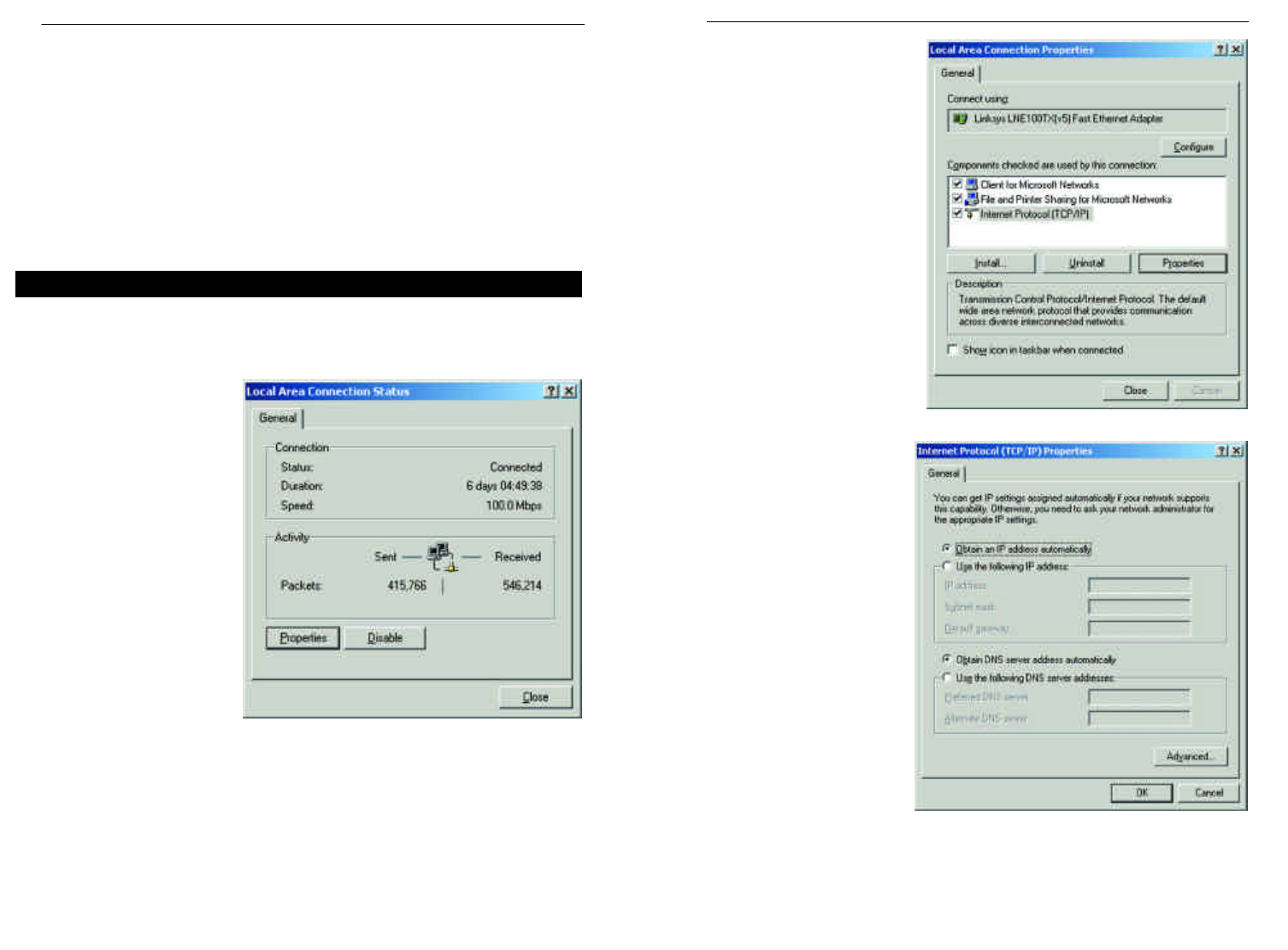
5. Click the OK button again. Windows may ask you for the original
Windows installation disk or additional files. Supply them by pointing to
the correct file location, e.g., D:\win98, D:\win9x,
c:\windows\options\cabs, etc. (This assumes that “D” is the letter of your
CD-ROM drive).
6. If Windows asks you to restart your PC, click the Yes button. If Windows
does not ask you to restart, restart your computer anyway.
Repeat steps 1-6 for each PC on your network. When all of your PCs are
configured, proceed to Chapter 4: Configuring the Router.
1. Click the Start button, click Settings and open the Control Panel. From
there, double-click the Network and Dial-up Connections icon. This will
display the Network screen.
2. Select the Local Area
Connection icon for the
applicable Ethernet
adapter (usually it is the
first Local Area
Connection listed).
3. When the Local Area Connection Status screen appears, click the
Properties button. (See Figure 3-3.)
4. Select Internet Protocol
(TCP/IP) (as shown in
Figure 3-4) and click the
Properties button.
5. Select Obtain an IP
address automatically
and verify that Obtain
DNS server address
automatically is select-
ed (as shown in Figure
3-5). Then, click the OK
button and click the OK
button on the subse-
quent screens to com-
plete the PC’s configura-
tion.
Repeat steps 1-5 for each PC on your network. When all of your PCs are
configured, proceed to Chapter 4: Configuring the Router.
Configuring Windows 2000 PCs
Figure 3-3
Figure 3-4
Figure 3-5
Instant WirelessTM Series Wireless Access Point Router with 4-Port Switch
13 14
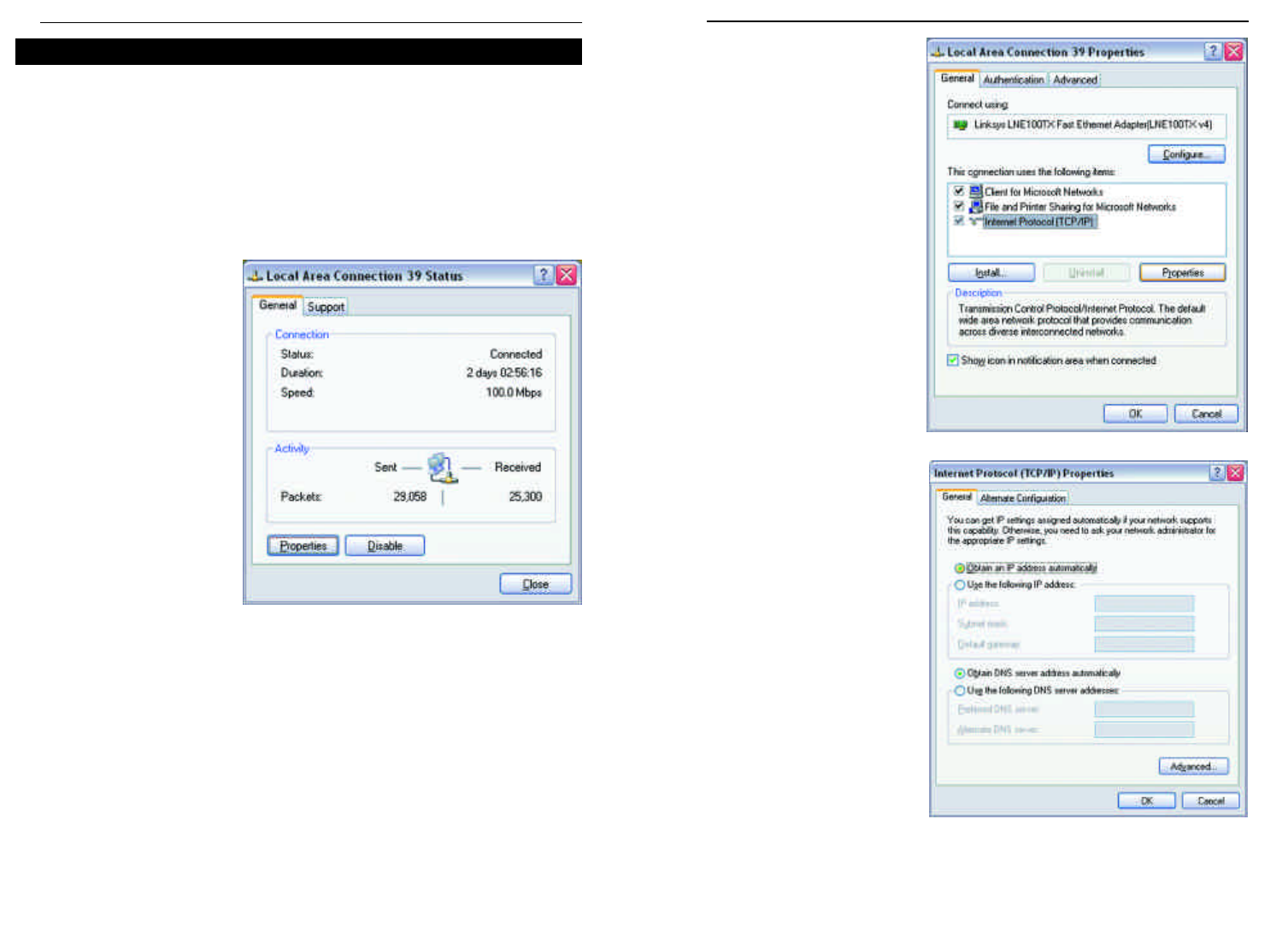
The following instructions assume you are running Windows XP’s default
interface. If you are using the Classic interface (where the icons and menus
look like previous Windows versions), please follow the instructions for
Windows 2000.
1. Click the Start button, open the Control Panel. and click the Network and
Internet Connections icon. Then, click the Network Connections icon to
display the Network screen.
2. Select the Local Area
Connection icon for
the applicable Ethernet
adapter (usually it is
the first Local Area
Connection listed).
3. When the Local Area Connection Status screen appears, click the
Properties button. (See Figure 3-6.)
4. Select Internet Protocol
(TCP/IP) (as shown in
Figure 3-7) and click the
Properties button.
5. Select Obtain an IP
address automatically
and verify that Obtain
DNS server address auto-
matically is selected (as
shown in Figure 3-8).
Then, click the OK button
and click the OK button on
the subsequent screens to
complete the PC’s configu-
ration.
Repeat steps 1-5 for each PC on your network. When all of your PCs are
configured, proceed to Chapter 4: Configuring the Router.
Configuring Windows XP PCs
Figure 3-6
Figure 3-7
Figure 3-8
Instant WirelessTM Series Wireless Access Point Router with 4-Port Switch
15 16
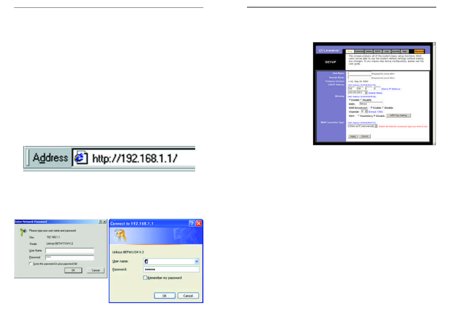
3. If required by your ISP, enter the Router’s Host Nameand Domain Name
in the appropriate fields on the Setup tab. (This is usually required by cable
ISPs.)
4. To configure the
Router for your wire-
less network, verify
that the Setup tab’s
Wireless fields (shown
in Figure 4-3) are
completed as follows:
Enable/Disable:
Selecting the Enable
radio button will
enable the Router’s
wireless feature.
Wireless functions
will not be available
unless enabled.
SSID: The SSID is a unique name for your wireless network. It is case sen-
sitive and must not exceed 32 characters. The default SSID is "linksys " but
you should change this to a personal wireless network name. All wireless
points in your network must use the same SSID.
SSID Broadcast - Allows the SSID to be broadcast on your network. You
may want to enable this function while configuring the Router, but make
sure that you disable it when you are finished. With this enabled, someone
could easily obtain the SSID information with site survey software and gain
unauthorized access to your network. Click Enable to broadcast. Click
Disable to increase network security and prevent the SSID from being seen
on networked PCs.
Channel: Select the appropriate channel for your network from the list pro-
vided. All wireless points in your network must use the same channel in
order to function properly.
Do not change the WEP setting from the default, “Disabled”, without first
referring to the Wireless Security sections of the User Guide or Setup
Wizard CD-ROM for advanced features and settings.
17 18
Chapter 4: Configuring the Router
This chapter will show you how to configure the Router to function in your net-
work and gain access to the Internet through your Internet Service Provider
(ISP). Detailed description of the Router’s Web-based Utility can be found in
the Chapter 5: Using the Router’s Web-Based Utility. Your ISP may require the
use of a Host Name and Domain Name. Further, you will set the WAN
Configuration Type on the Router’s Setup tab from the information given by
your ISP. You will need this setup information from your ISP. If you do not have
this information, please contact your ISP before proceeding.
The instructions from your ISP tell you how to set up your PC for Internet
access. Since you are now using the Router to share Internet access among sev-
eral computers, you will use this setup information for Router configuration.
1. Open your web browser, and enter 192.168.1.1 into the web browser’s
Address field, as shown in Figure 4-1. Then, press the Enter key.
2. An Enter Network Password window, shown in Figure 4-2a, will appear.
(Windows XP users will see a Connect to 192.168.1.1 window, shown in
Figure 4-2b.) Leave the User Name field empty, and enter admin (the
default password) in lowercase letters in the Password field. Then, click the
OK button.
Figure 4-1
Figure 4-2a
Figure 4-2b
Figure 4-3
Instant WirelessTM Series Wireless Access Point Router with 4-Port Switch
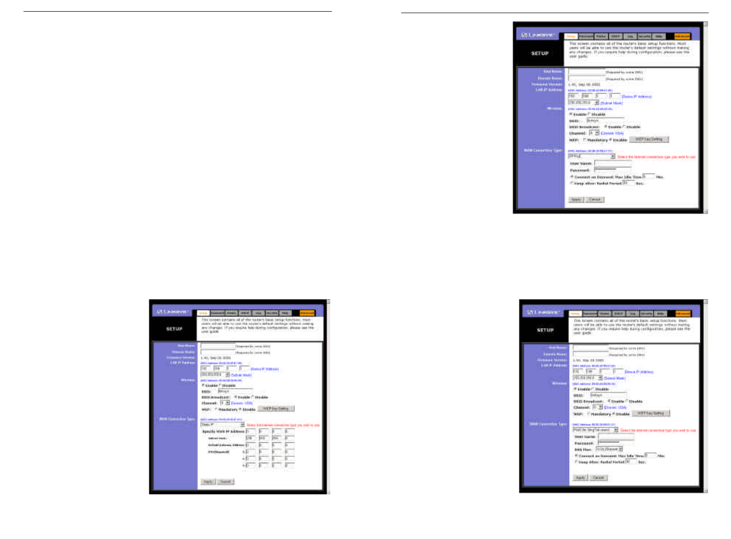
PPPoE
If your DSL provider
says that you are con-
necting through PPPoE
or if you normally enter
a user name and pass-
word to access the
Internet, perform these
steps (shown in Figure
4-5):
a. Select PPPoE as the
WAN Connection
Type.
b. Enter the User
Name.
c. Enter the Password.
d. Click the Apply button to save the settings.
RAS (for SingTel Users)
RAS is a service used in
Singapore only. If you are
using a RAS connection
(as shown in Figure 4-6),
check with your ISP for
the necessary setup infor-
mation.
19 20
5. The Router supports five connection types: DHCP (obtain an IP automati-
cally), PPPoE, Static IP Address, RAS, and PPTP. These types are selected
from the drop-down menu beside WAN Connection Type. The Setup tab
and available features will differ depending on what kind of connection type
you select, the instructions for which are included here:
Obtain an IP Automatically
If your ISP says that you are connecting through a dynamic IP address (or
DHCP), perform these steps:
a. Select Obtainan IP automatically as the WAN Connection Type (as
previously shown in Figure 4-3).
b. Click the Apply button to save the settings.
Static IP
If your ISP says that you are connecting through a static (or fixed) IP
address, perform these steps (as shown in Figure 4-4):
a. Select Static IP as the WAN Connection Type.
b. In the fields beside
“Specify WAN IP
Address”, enter the IP
Address.
c. Enter the Subnet Mask.
d. Enter the Default
Gateway Address.
e. Enter the DNS in the 1,
2, and/or 3 fields. You
must enter at least one
DNS address.
f. Click the Apply button
to save the settings.
Figure 4-4
Figure 4-5
Figure 4-6
Instant WirelessTM Series Wireless Access Point Router with 4-Port Switch
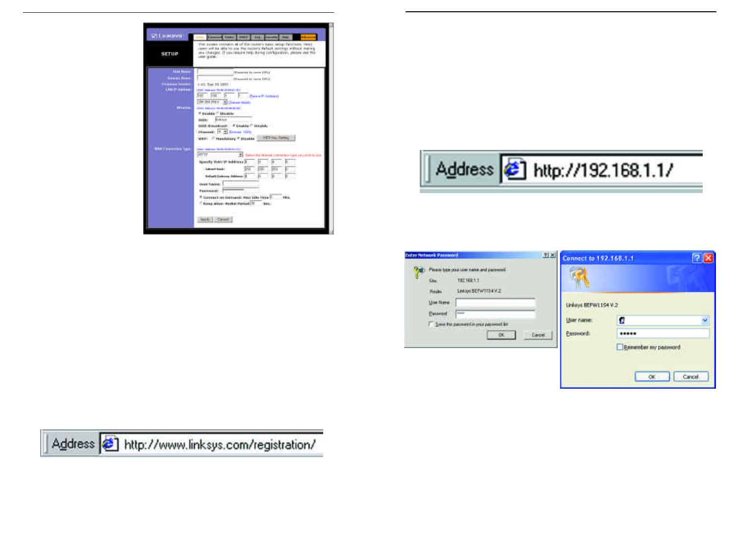
Chapter 5: Using the Router’s Web-
Based Utility
For your convenience, an administrative utility has been programmed into the
Router. This chapter will explain all of the functions in this utility. All router-
based administrative tasks are performed through this web utility. The web util-
ity can be accessed by any PC on the network by typing “http://192.168.1.1” in
the PC’s web browser address window, as shown in Figure 5-1.
Upon entering the address into the web browser, a password request page will
pop up, as shown in Figure 5-2a. (Windows XP users will see a “Connect to
192.168.1.1” window, shown in Figure 5-2b.)
Leave the User Name field empty, and enter admin (the default password) in
lowercase letters in the Password field. Then, click the OK button.
In this chapter, you will find brief descriptions of each of the utility’s tabs and
its more important functions. More detailed explanations and instructions can
be found by clicking each page’s Help button or on Linksys’s website at
www.linksys.com. To clear any values you’ve entered on any page, click the
Cancel button. To apply any settings you’ve altered on any page, click the
Apply button.
21
PPTP
PPTP is a service used in
Europe only. If you are
using a PPTP connection
(as shown in Figure 4-7),
check with your ISP for
the necessary setup infor-
mation.
6. If you haven’t already done so, click the Apply button to save the settings.
7. Reset the power on your cable or DSL modem and restart your computers.
They will now obtain the Router's new settings.
Note: You only need to configure the Router from one computer. If you
need advanced setting information, please refer to the Linksys support web-
site at support.linksys.com or the User Guide on the Setup Wizard CD-
ROM.
Congratulations! You’ve successfully configured the Router. You can test
the setup by opening your web browser from any computer and entering
www.linksys.com/registration (as shown in Figure 4-8).
If you are unable to reach our website, you may want to review what you
did in this section or refer to the Troubleshooting Appendix.
Figure 4-7
Figure 4-8
Figure 5-1
Figure 5-2a
Figure 5-2b
Instant WirelessTM Series Wireless Access Point Router with 4-Port Switch
22
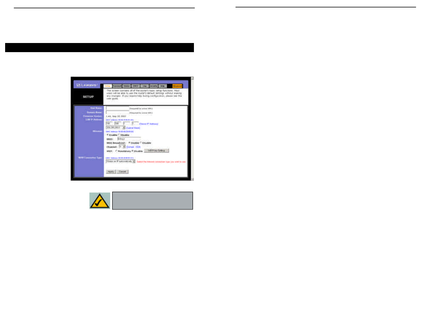
• SSID: The SSID is a unique name for your wireless network. It is case sensi-
tive and must not exceed 32 characters. The default SSID is "linksys " but you
should change this to a personal wireless network name. All wireless points
in your network must use the same SSID. Verify that you are using the correct
SSID and click the Apply button to set it.
•SSID Broadcast - Allows the SSID to be broadcast on your network. You may
want to enable this function while configuring the Router, but make sure that
you disable it when you are finished. With this enabled, someone could easily
obtain the SSID information with site survey software and gain unauthorized
access to your network. Click Enable to broadcast. Click Disable to increase
network security and prevent the SSID from being seen on networked PCs.
•Channel Select the appropriate channel from the list provided to correspond
with your network settings, between 1 and 11. (Higher channels can only be
used outside of the United States and Canada.) All points in your wireless net-
work must use the same channel in order to function correctly. Verify that the
correct channel is selected and click the Apply button to set it.
•WEP (Mandatory/Disable). In order to utilize WEP encryption, select
Enable. If you do not wish to utilize WEP encryption, make sure Disable is
selected.
•WEP Key Setting When WEP Encryption is Enabled, press this button to
modify the WEP Key Settings.
For further details on configuring Wireless Security, using WEP, refer to
Appendix C: Configuring Wireless Security.
•WAN Connection Type The Router supports five connection types: DHCP
(obtain an IP automatically), PPPoE, Static IP Address, RAS, and PPTP. These
types are selected from the drop-down menu beside WAN Connection Type.
The Setup tab and available features will differ depending on what kind of
connection type you select. Each option is described on the following pages.
Obtain an IP Automatically
If your ISP says that you are connecting through a dynamic IP address (or
DHCP), select this option from the drop-down menu (as shown in Figure 5-3).
Now, the Router will accept the dynamic IP addresses assigned by your ISP
when connecting to the Internet.
23 24
The utility’s tabs: Setup, Password, Status, DHCP, Log, Security and Help are
used for Basic Setup of the Router. When the Advanced Tab is clicked, further
options will be displayed for Filters, Forwarding, Dynamic Routing, Static
Routing DMZ Host, MAC Address Cloning, and Wireless configuration.
The Setup tab is the first tab you will see when you access the Utility. If you
have already installed and set up the Router, you have already seen this tab and
have already properly configured all of the values.
•Host Name This
entry is necessary
for some ISPs and
can be provided by
them.
•Domain Name
This entry is neces-
sary for some ISPs
and can be provided
by them.
•Firmware Version
This displays the
firmware version
the Router is cur-
rently using. As future ver-
sions of the Router’s
firmware become available,
they can be downloaded from the Linksys website at www.linksys.com.
•LAN IP Address and Subnet Mask This is the Router’s IP Address and
Subnet Mask as seen on the internal LAN. The default value is 192.168.1.1
for IP Address and 255.255.255.0 for Subnet Mask.
•Wireless (Enable/Disable). In order to utilize the Router’s wireless func-
tions, select Enable. If you do not wish to utilize any wireless functions,
make sure Disable is selected. (Note: No other wireless functions will be
available unless you enable this setting.)
Setup
Figure 5-3
Note: Due to differences in web
browsers, some screen shots may differ.
Instant WirelessTM Series Wireless Access Point Router with 4-Port Switch
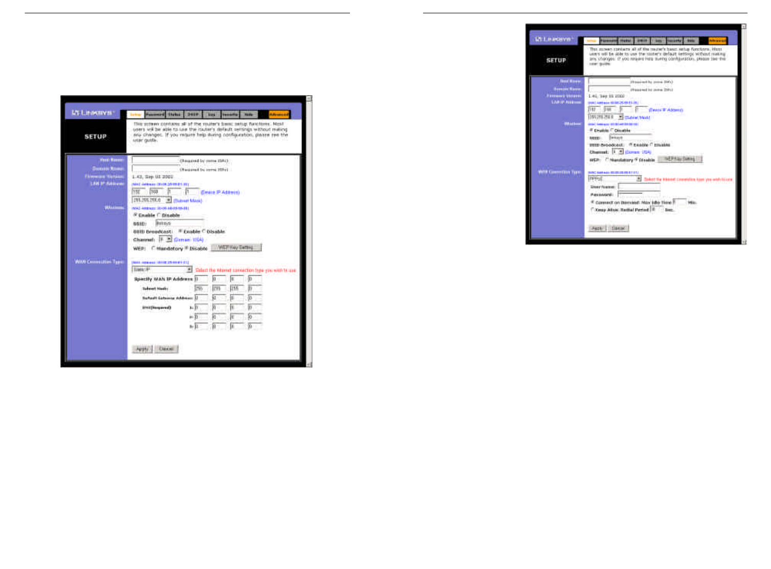
25
PPPoE
Some DSL-based
ISPs use PPPoE
(Point-to-Point
Protocol over
Ethernet) to estab-
lish communica-
tions with an end-
user. If you are
using a DSL line,
check with your ISP
to see if they use
PPPoE. If they do
use PPPoE, select
this from the drop-
down menu (as
shown in Figure 5-
5).
If you do enable PPPoE, remember to remove any existing PPPoE applica-
tions already on any of your PCs.
•User Name and Password Enter the User Name and Password you use
when logging onto your ISP connection.
•Connect on Demand and Max Idle Time You can configure the Router
to disconnect your ISP connection after a specified period of time (Max
Idle Time). If you have been disconnected due to inactivity, Connect on
Demand enables the Router to automatically re-establish your connection as
soon as you attempt to access the Internet again. If you wish to activate
Connect on Demand, click the radio button. If you want your Internet con-
nection to remain on at all times, enter 0in the Max Idle Time field.
Otherwise, enter the number of minutes you want to have elapsed before
your Internet access disconnects.
•Keep Alive Option and Redial PeriodThis option keeps you connected to
your ISP indefinitely, even when your connection sits idle. To use this
option, click the radio button next to Keep Alive. The default Redial Period
is 30 seconds.
26
Static IP
If your ISP says that you are connecting through a static (or fixed) IP
address, select this option from the drop-down menu (as shown in Figure 5-
4). The Router will utilize that static IP Address when the following infor-
mation is entered into the appropriate field:
•WAN IP Address and Subnet Mask This is the Router’s IP Address and
Subnet Mask as seen by external users on the Internet (including your
ISP).
• Default Gateway Address Your ISP will provide you with the Gateway
IP Address.
• DNS (Domain Name Server) IP Address Your ISP will provide you
with at least one DNS IP Address.
Figure 5-4
Figure 5-5
Instant WirelessTM Series Wireless Access Point Router with 4-Port Switch
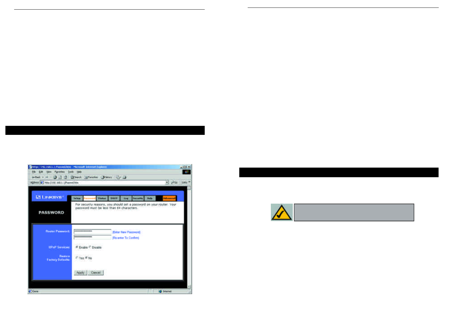
28
•Router Password For greater security, you should set a password for the
Router. If you don’t set the password, all users on your network will be able
to access the Router using the default password admin. We recommend that
you change your password often.
• UPnP Services Universal Plug and Play (UPnP) allows systems, such as
Windows XP PCs to automatically configure the Router for various Internet
applications, such as gaming and videoconferencing. Click the radio button
next to Enable to enable UPnP Services, or Disable to disable UPnP
Services.
• Restore Factory Defaults If you select the Restore Factory Default option
and click the Apply button, you will clear all of the Router’s settings and
restore the default settings.
Do not restore the factory defaults unless you are having difficulties with the
Router and have exhausted all other troubleshooting measures. Once the Router
is reset, you will have to re-enter all of your configuration data.
To clear any values you’ve entered on any page, click the Cancel button. To
apply any settings you’ve altered on any page, click the Apply button.
The Status tab, shown in Figure 5-8, displays the Router’s current status; it
reflects the data and selections you’ve entered using the Setup tab and provides
options for DHCP users.
All of the information provided on the Status tab is read-only and can be
changed using the Setup tab.
•Host Name This field shows the name of the Router. This entry is neces-
sary for some ISPs.
•Firmware Version This field shows the installed version and date of the
firmware. Version dates are slightly more accurate than version numbers.
•Login This indicates if you are using a dial-up style connection like
PPPoE, RAS, or PPTP. For PPPoE, RAS, or PPTP only, there is a Connect
button to click if you are disconnected and want to re-establish a connec-
tion.
RAS (for SingTel Users)
RAS is a service used in Singapore only. If you are using a RAS connection
(as shown in Figure 4-6), check with your ISP for the necessary setup infor-
mation.
PPTP
PPTP is a service used in Europe only. If you are using a PPTP connection
(as shown in Figure 4-7), check with your ISP for the necessary setup infor-
mation.
You can confirm that the above settings are correct by successfully connecting
to the Internet.
To clear any values you’ve entered on any page, click the Cancel button. To
apply any settings you’ve altered on any page, click the Apply button.
From the Password tab, shown in Figure 5-7, you can change the Router’s
Password, enable Universal Plug and Play (UPnP) Services for systems such as
Windows XP PCs, and restore the Router’s factory default settings.
Password
Figure 5-7
Status
Note: The information provided on the Status
tab may vary depending on the Router’s settings.
Instant WirelessTM Series Wireless Access Point Router with 4-Port Switch
27
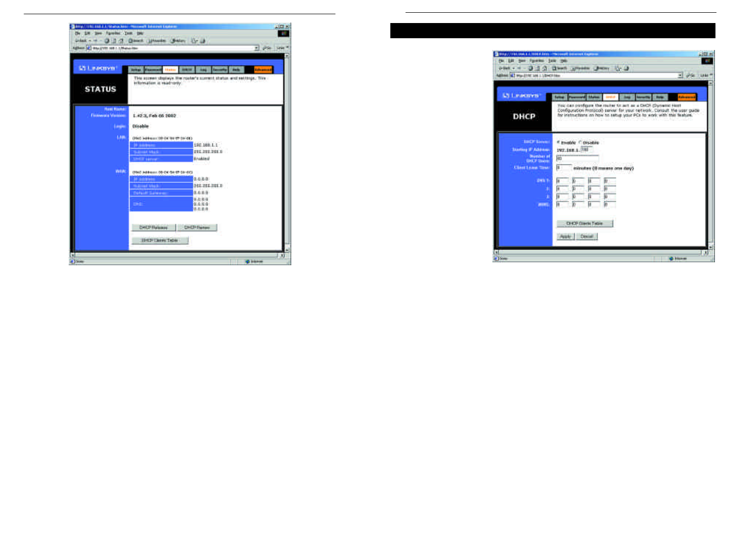
29
A DHCP (Dynamic
Host Configuration
Protocol) Server
automatically
assigns IP addresses
to each computer on
its network. Unless
you already have
one, you should set
the Router up as a
DHCP server. This
is done on the DHCP
tab, shown in Figure
5-9.
•DHCP Server Click the Enable option to enable the Router’s DHCP serv-
er function If you already have a DHCP server on your network, set the
Router’s DHCP option to Disable.
•Starting IP Address Enter a numerical value for the DHCP server to start
with when issuing IP addresses.
•Number of DHCP users Enter the maximum number of PCs that will
require IP addresses assigned by the Router. No more than 253 computers
can be used. In order to determine the DHCP IP Address range, add the
starting IP address (e.g., 100) to the number of DHCP users. By default, as
shown in Figure 5-9, if you add 50 users, the range or IP Addresses will be
192.168.1.100 to 192.168.1.149.
•Client Lease Time The Client Lease Time is the amount of time a network
user will be allowed connection to the Router with their current dynamic IP
address. Enter the amount of time, in minutes, that the user will be “leased”
this dynamic IP address.
DHCP
30
•LAN These fields display the current IP Address and Subnet Mask of the
Router, as seen by users on your local area network. The DHCP Server field
shows the status of the Router’s DHCP server function, which is either
enabled or disabled.
•WAN These fields display the WAN IP Address, WAN Subnet Mask, and
WAN Default Gateway IP Address of the Router, as seen by external users on
the Internet. The DNS (Domain Name System) IP Address fields show the IP
address(es) of the DNS currently used by the Router. Multiple DNS IP set-
tings are common. In most cases, the first available DNS entry is used.
•DHCPRelease Click the DHCP Release button to delete the current IP
address of the device connected to the Router’s WAN port.
•DHCPRenew Click the DHCP Renew button to replace the current IP
address—of the device connected to the Router’s WAN port—with a new IP
address.
•DHCPClients Table This table lists the PCs that were given IP addresses by
the Router.
Figure 5-9
Figure 5-8
Instant WirelessTM Series Wireless Access Point Router with 4-Port Switch
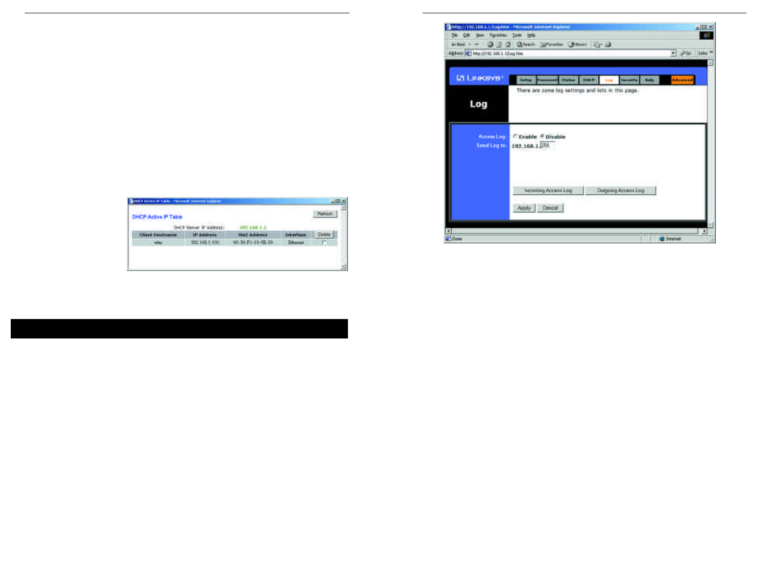
For a permanent record of these logs, Logviewer software must be used. This
software is downloadable from the Linksys website at www.linksys.com. The
Logviewer saves all incoming and outgoing activity as a permanent file on your
PC’s hard drive. Next to “Send Log to”, enter the fixed IP address of the PC
running the Logviewer software. The Router will now send updated logs to that
PC.
To clear any values you’ve entered on any page, click the Cancel button. To
apply any settings you’ve altered on any page, click the Apply button.
32
•DNS The Domain Name System (DNS) is how the Internet translates
domain or website names into Internet addresses or URLs. Your ISP will
provide you with at least one DNS Server IP Address. If you wish to use
another, type that IP Address in one of these fields. You can type up to
three DNS Server IP Addresses here. The Router will use these for quicker
access to functioning DNS servers.
•WINS The Windows Internet Naming Service (WINS) manages each PC’s
interaction with the Internet. If you use a WINS server, enter that server’s
IP Address here. Otherwise, left this blank.
•DHCP Clients Table When this button is clicked, a table similar to that
shown in Figure 5-10 appears, displaying a list of PCs assigned IP address-
es by the Router. Click the Refresh button to display the most current
information. If you
wish to delete a
client’s IP address,
select that client by
clicking the box to
the right and click
the Delete button.
To clear any values you’ve entered on any page, click the Cancel button. To
apply any settings you’ve altered on any page, click the Apply button.
The Log tab, shown in Figure 5-11, provides you with a log of all incoming and
outgoing URLs or IP addresses for your Internet connection.
To access activity logs, select the Enable option next to “Access Log”. This
function can be disabled by clicking the Disable radio button.
With logging Enabled, you can choose to view temporary logs or have a per-
manent record, using the Logviewer software. Temporary logs can be accessed
from the Log tab by clicking either the Incoming Access Log or Outgoing
Access Log buttons. The Incoming Access Log gives you a log of all the
incoming Internet traffic while the Outgoing Access Log lists all the URLs and
IP addresses of Internet sites that users on your network have accessed.
Figure 5-10
Log
Figure 5-11
Instant WirelessTM Series Wireless Access Point Router with 4-Port Switch
31
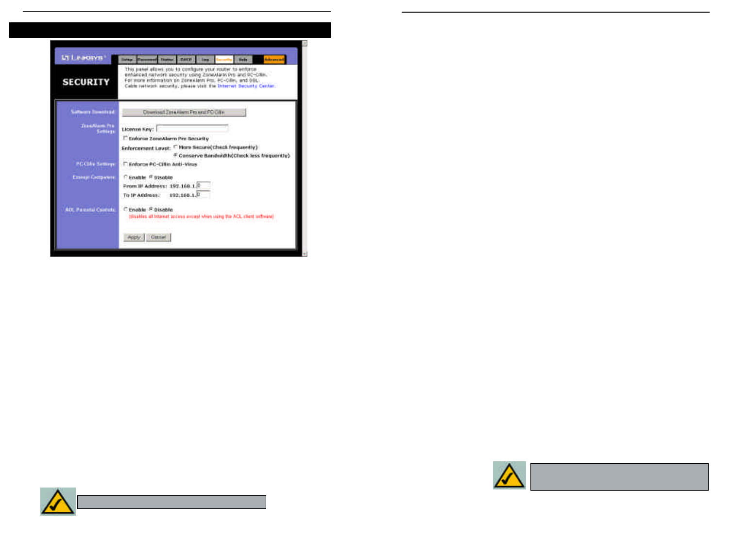
The Security tab, as shown in Figure 5-12, enables configuration of the Router
to provide enhanced network security using ZoneAlarm Pro and PC-cillin
(each sold separately). While the Router provides a built-in Internet NAT fire-
wall, ZoneAlarm Pro enhances the Router’s security capabilities for increased
protection against hackers and other threats from the Internet and PC-cillin pro-
tects against viruses. ZoneAlarm Pro and PC-cillin work independently of each
other. For more information on ZoneAlarm Pro, PC-cillin, and DSL or cable
network security, please click the on-screen link to the Internet Security Center.
Software Download
Click this button to purchase and download ZoneAlarm Pro and/or PC-cillin at
the Internet Security Center. Print the summary page, which contains the
license key needed for installation, or write down the license key if you are
unable to print the page. You will also be e-mailed a confirmation invoice with
the key included. When adding security enhancements to your other networked
computers, you can either copy the downloaded files to the other PCs or re-
download the software on each individual PC without incurring any more costs.
ZoneAlarm Pro Settings
If you have downloaded ZoneAlarm Pro, complete this section.
License Key Enter the License Key for ZoneAlarm Pro. The License Key
will be e-mailed to you after you purchase ZoneAlarm Pro.
Enforce ZoneAlarm Pro Security Check this box to enable ZoneAlarm Pro
on the Router. This will require every PC to have ZoneAlarm Pro installed
before being allowed to access the Internet (except for exempt computers).
Enforcement Level This sets how often ZoneAlarm Pro will check for unau-
thorized intrusions. More Secure (default setting) enables ZoneAlarm Pro to
check frequently. Conserve Bandwidth enables ZoneAlarm Pro to check less
frequently; this uses less bandwidth. It is recommended to set the Enforcement
Level at the More Secure setting unless there is a decrease in the Router’s per-
formance.
PC-cillin Settings
If you have downloaded PC-cillin, complete this section.
Enforce PC-cillin Anti-Virus Check this box to enable PC-cillin Anti-Virus
on the Router.
Exempt Computers
If you wish to exempt any computers from enforcement of ZoneAlarm Pro and/or
PC-cillin, complete this section.
Enable/Disable To enable or disable computer exemptions, click Enable or
Disable.
From IP Address/To IP Address Enter the range of IP addresses for the
computers you want to exempt from enforcement of ZoneAlarm Pro and/or
PC-cillin.
AOL Parental Controls
Enabling this engages AOL’s proprietary “Parental Control” feature. Enabling this
will disable all options under the Advanced tab except MAC Address cloning.
To apply any of the settings you change on a page, click the Applybutton. To can-
cel any values you’ve entered on any page, click the Cancel button.
Security
Note:Your license key will be e-mailed to you.
Figure 5-12
Instant WirelessTM Series Wireless Access Point Router with 4-Port Switch
33 34
Note: AOL Parental Controls are available
to AOL customers in the Unites States Only.
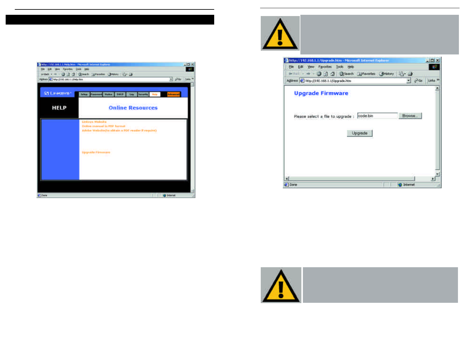
2. Click the Browse button and find the firmware upgrade file that you
downloaded from the Linksys website. Double-click the upgrade file.
This will place the file into the “File Path:” field.
3. When the correct file is in the “File Path:” field, click the Upgrade but-
ton and follow the instructions there. This will complete your firmware
upgrade.
Filters
35
Important:Do not interrupt the firmware upgrade process in
any way or power down the Router while the upgrade is in
progress as this could damage the Router.
The Help tab, as shown in Figure 5-13, contains links to all of the Utility’s inter-
nal support documentation, a link to Linksys’s website, and the application that
upgrades the Router’s firmware. To utility these links, you must have an active
Internet connection.
Click the Linksys Website link to connect to the Linksys homepage for
Knowledgebase help files and information about other Linksys products.
For an Online Manual in PDF format, click that text link. The manual will appear
in Adobe PDF format. If you do not have the Adobe PDF Reader installed on your
computer, click the Adobe Website link to download this software.
Firmware can be upgraded by clicking the Upgrade Firmware link. Do not upgrade
your firmware unless you are experiencing problems with the Access Point.
To upgrade the Router’s firmware:
1. Access the Help tab and click Upgrade Firmware. A new page, shown in
Figure 5-14, will appear.
36
Important: In order to upgrade the Router’s firmware, you
must use Internet Explorer 5.0 or higher, or Netscape
Navigator 4.7 or higher. Upgrading the firmware may cause
the Router to be reset to the factory defaults. Make a record of
all settings before attempting the upgrade.
Help
Figure 5-13
Figure 5-14
Instant WirelessTM Series Wireless Access Point Router with 4-Port Switch
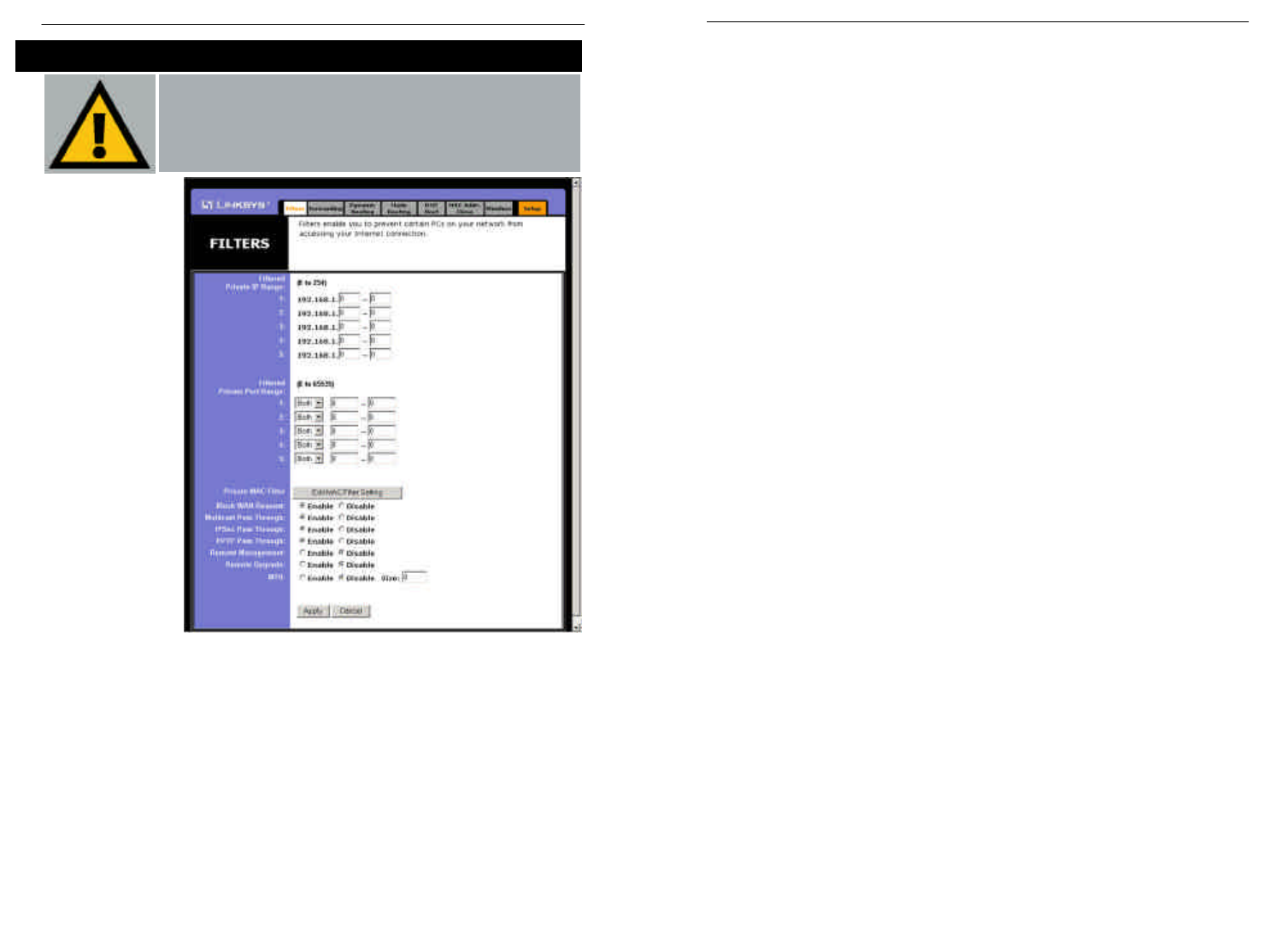
To filter users by network port number, enter a network port number or a
range of network ports. Enter the port numbers you want to filter in the port
numbers fields. Users connected to the Router will no longer be able to
access any port number listed there.
•Editing MAC Filter Setting
This feature filters the Ethernet adapter’s specific MAC address from going
out to the Internet.
To check your Ethernet adapter’s MAC address, run winipcfg or ipconfig
in the command prompt, depending on which Windows operating system
you are using. To set the MAC filter, click the Edit MAC Filter Setting
button. When a second window appears, select the range in the drop-down
menu, and in a MAC number field, enter the 12-digit MAC address you
want to filter. Click the Apply button before closing the window. For infor-
mation on obtaining a MAC address, go to Appendix D: Finding the MAC
Address and IP Address for Your Ethernet Adapter.
•Blocking WAN Requests
By enabling the Block WAN Request feature, you can prevent your network
from being “pinged,” or detected, by other Internet users. The Block WAN
Request feature also reinforces your network security by hiding your net-
work ports. Both functions of the Block WAN Requestfeature make it more
difficult for outside users to work their way into your network.
Click the Apply button to save your changes.
•Using Multicast Pass Through
This feature allows for multiple transmissions to specific recipients at the
same time. Select Enable to support the feature, or Disable to keep the
Router from multicasting.
37
Filters block spe-
cific internal users
from accessing the
Internet. From the
Filters tab, as
shown in Figure 5-
15, you can set up a
filter through an IP
address or a net-
work port number.
•Setting Up Filters
To set up a filter using IP addresses, enter the range of IP addresses you
wish to filter in the IP address fields. Users who have filtered IP addresses
will not be able to access the Internet at all. If you only want to filter one
IP address instead of a range of IP addresses, enter the same value into both
fields. For instance, if you wish to filter the PC with the IP address of
192.168.1.5, enter 5into both fields on one line: 192.168.1.5 ~ 192.168.1.5.
Click the Apply button when you’re done.
38
Advanced Tab: Filters
Important: Filtering is an Advanced Function. No changes
should be made to this tab without a thorough understanding
of networking concepts.
Figure 5-15
Instant WirelessTM Series Wireless Access Point Router with 4-Port Switch
•Using Multicast Pass Through
This feature allows for multiple transmissions to specific recipients at the
same time. Select Enable to support the feature, or Disable to keep the
Router from multicasting.
•Using IPSec Pass Through
This feature lets you use IPSec Pass Through. To use this feature, click the
Enable button next to IPSec Pass Through, and then the Apply button.
IPSec Pass Through is enabled by default. To disable IPSec Pass Through,
click on Disable and then the Apply button.
•Using PPTP Pass Through
Point-to-Point Tunneling Protocol is the method used to enable VPN
sessions. To enable this feature, click the Enable button next to PPTP Pass
Through, and click the Apply button.
PPTP Pass Through is enabled by default. To disable this feature, click on
Disable next to PPTP Pass Through, and then the Apply button.
•Using Remote Management
This feature allows you to manage the Router from a remote location, such
as over the Internet. To enable this feature, click on Enable, and click the
Apply button. Remote Management must be activated before you can man-
age the Router from a remote location.
To disable Remote Management, click on Disable, and click the Apply but-
ton. If you wish to use this feature, enter http:\\<WAN IP Address>:8080
into your web browser’s address field and press the Enter key. (Enter your
specific WAN IP Address in place of <WAN IP Address>.)
To disable this feature, click on Disable, and click the Apply button.
•Using Remote Upgrade
This feature allows you to upgrade the Router’s firmware from a remote
location. To enable Remote Upgrade, click on Enable, and then click the
Apply button. Remote Management must be activated before you can man-
age the Router from a remote location.
•Using MTU (Maximum Transmission Unit)
This feature specifies the largest packet size permitted for network trans-
mission. Select Enable and enter the value desired. It is recommended that
you leave this value in the 1200 to 1500 range. For most DSL users, it is
recommended to use the value 1492. By default, MTU is set at 1500 when
disabled.
Important:Upgrading may cause the
Router to be reset to the factory
defaults. Make a record of all set-
tings before attempting the upgrade.
Instant WirelessTM Series Wireless Access Point Router with 4-Port Switch
39 40
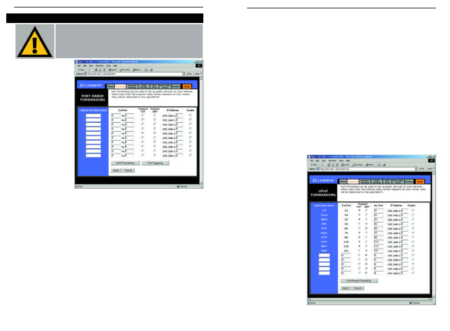
3. On the same line, select the protocol TCP or UDP, or select both protocols.
4. Enter the IP address of the server that you want the Internet users to be
able to access. To find the IP address, go to Appendix D: Finding the MAC
Address and IP Address for Your Ethernet Adapter.
5. Check the Enable box to enable the services you have defined. Port Range
Forwarding will not function if the Enable button is left unchecked. This is
disabled (unchecked) by default.
6. Configure as many entries as needed—the Router supports up to 10 ranges
of ports. Click the Apply button when you are done.
UPnP Forwarding
Clicking the UPnP Forwarding button on the Port Range Forwarding tab will
display the UPnP Forwarding tab. The UPnP Forwarding tab, shown in Figure
5-17, displays preset application settings as well as options for customization
of port services for other applications.
This table is similar to
the Port Forwarding
table, but the items on
this table will automat-
ically synchronize with
other UPnP devices
and operating systems,
such as Windows XP.
Figure 5-17
Port Range Forwarding
from this tab, as shown
in Figure 5-16, sets up
public services on your
network, such as web
servers, ftp servers, e-
mail servers, or other
specialized Internet
applications.
(Specialized Internet
applications are any
applications that use
Internet access to per-
form functions such as
videoconferencing or
online gaming. Some
Internet applications
may not require any
forwarding.) When
users send this type of request to your network via the Internet, the Router will
forward those requests to the appropriate PC. Before using Forwarding, the
DHCP function on the PC whose port is being forwarded must be disabled and
have a new static IP address assigned because its IP address may change when
using the DHCP function.
If you need to forward all ports to one PC, see the “DMZ” section.
To add a server using Port Range Forwarding:
1. Enter the name of the application in the appropriate Customized
Applications field.
2. Next to the name of the application, enter the number or range of the
external port(s) used by the server or Internet application in the Ext. Port
column. Check with the Internet application software documentation for
more information. 42
Advanced Tab: Port Range Forwarding
Important: Port Range Forwarding is an Advanced
Function. No changes should be made to this tab without a
thorough understanding of networking concepts.
Figure 5-16
Instant WirelessTM Series Wireless Access Point Router with 4-Port Switch
41

• POP3 (Post Office Protocol 3) A standard mail server commonly used on
the Internet. It provides a message store that holds incoming e-mail until
users log on and download it. POP3 is a simple system with little selectivity.
All pending messages and attachments are downloaded at the same time.
POP3 uses the SMTP messaging protocol.
• NNTP (Network News Transfer Protocol) The protocol used to connect to
Usenet groups on the Internet. Usenet newsreaders support the NNTP pro-
tocol.
• SNMP (Simple Network Management Protocol) A widely used network
monitoring and control protocol. Data is passed from SNMP agents, which
are hardware and/or software processes reporting activity in each network
device (hub, router, etc.) to the workstation console used to oversee the net-
work. The agents return information contained in a MIB (Management
Information Base), which is a data structure that defines what is obtainable
from the device and what can be controlled (turned off, on, etc.).
You must check the Enable box to enable the applications you have defined.
To add a server using UPnP Forwarding:
1. Enter the name of the application in the appropriate Application Name
field.
2. Next to the name of the application, enter the number of the external port
used by the server in the Ext. Port column. Check with the Internet appli-
cation software documentation for more information.
3. On the same line, select the protocol UDP or TCP.
4. Enter the number of the internal port used by the server in the Int. Port col-
umn. Check with the Internet application software documentation for more
information.
5. Enter the IP address of the server that you want the Internet users to be able
to access. To find the IP address, go to Appendix D: Finding the MAC
Address and IP Address for Your Ethernet Adapter.
6. Check the Enable box to enable the services you have defined. UPnP
Forwarding will not function if the Enable button is left unchecked. This is
disabled (unchecked) by default.
The Preset Applications are among the most widely used Internet applications
that may require forwarding. They include the following:
• FTP (File Transfer Protocol) A protocol used to transfer files over a TCP/IP
network (Internet, UNIX, etc.). For example, after developing the HTML
pages for a website on a local machine, they are typically uploaded to the
web server using FTP. FTP includes functions to log onto the network, list
directories, and copy files. It can also convert between the ASCII and
EBCDIC character codes. FTP operations can be performed by typing com-
mands at a command prompt or via an FTP utility running under a graphical
interface such as Windows. FTP transfers can also be initiated from within a
web browser by entering the URL preceded by ftp://.
• Telnet A terminal emulation protocol commonly used on Internet and
TCP/IP-based networks. It allows a user at a terminal or computer to log onto
a remote device and run a program.
• SMTP (Simple Mail Transfer Protocol) The standard e-mail protocol on the
Internet. It is a TCP/IP protocol that defines the message format and the
message transfer agent (MTA), which stores and forwards the mail.
• DNS (Domain Name System) The way that Internet domain names are
located and translated into IP addresses. A domain name is a meaningful and
easy-to-remember “handle” for an Internet address.
• TFTP (Trivial File Transfer Protocol) A version of the TCP/IP FTP proto-
col that has no directory or password capability.
• Finger A UNIX command widely used on the Internet to find out informa-
tion about a particular user, such as a telephone number, whether the user is
currently logged on, and the last time the user was logged on. The person
being “fingered” must have placed his or her profile on the system in order
for the information to be available. Fingering requires entering the full
user@domain address.
• HTTP (HyperText Transport Protocol) The communications protocol used
to connect to servers on the World Wide Web. Its primary function is to
establish a connection with a web server and transmit HTML pages to the
client web browser.
Instant WirelessTM Series Wireless Access Point Router with 4-Port Switch
43 44
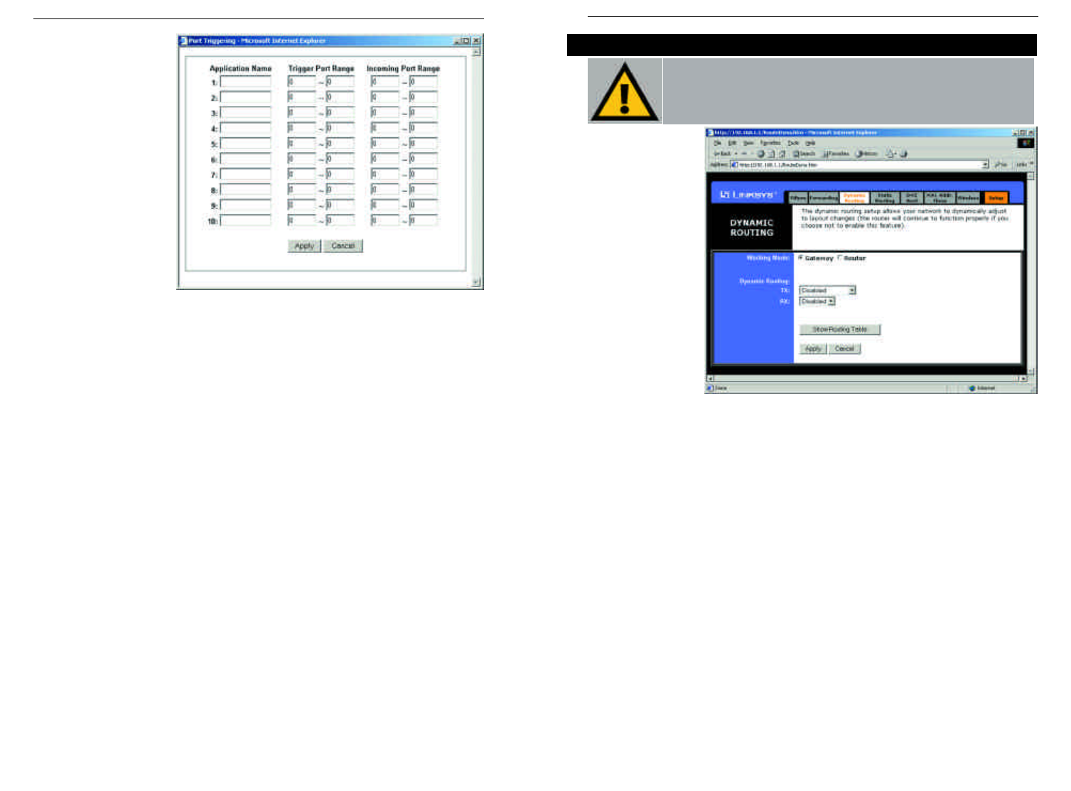
From the Dynamic
Routing tab, shown
in Figure 5-19, you
can automatically
adjust to physical
changes in the net-
work’s layout. The
Router, using the
RIP protocol,
determines the net-
work packets’
route based on the
fewest number of
hops between the
source and the des-
tination. The RIP
protocol regularly broadcasts routing information to other routers on the net-
work. To set up Dynamic Routing:
1. Choose the correct Working Mode. Gateway Mode should be used if the
Router is hosting your network’s connection to the Internet. Router Mode
should be selected if the Router exists on a network with other routers.
2. In the TX field, choose the protocol by which you transmit data on the net-
work.
3. In the RX field, choose the protocol by which the Router receives network
data.
4. Click the Apply button to save your changes.
To view the Routing Table, which shows the network layout, click the Show
Routing Table button.
To clear any values you’ve entered on any page, click the Cancel button. To
apply any settings you’ve altered on any page, click the Apply button.
45
Advanced Tab: Dynamic Routing
Important: Dynamic Routing is an Advanced Function. No
changes should be made to this tab without a thorough under-
standing of networking concepts.
Figure 5-19
Port Triggering
From the Port Range
Forwarding tab, shown
in Figure 5-18, click
the Port Triggering
button to allow the
Router to watch out-
going data for specific
port numbers. The IP
address of the comput-
er that sends the
matching data is
remembered by the
Router, so that when
the requested data
returns through the Router, the data is pulled back to the proper computer by
way of IP address and port mapping rules.
1. Enter the Application Name of the trigger.
2. Enter the Trigger Port Range used by the application. Check with the
Internet application for the port number needed.
3. Enter the Incoming Port Range used by the application. Check with the
Internet application for the port number needed.
4. Click the Apply button.
Figure 5-18
Instant WirelessTM Series Wireless Access Point Router with 4-Port Switch
46
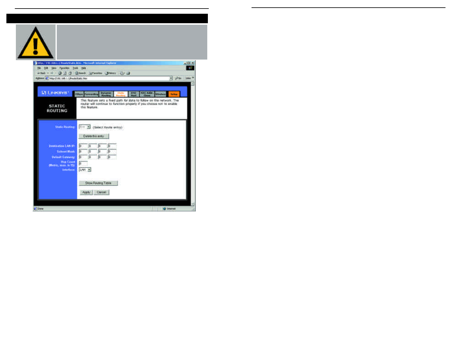
2. Enter the following data to create a new static route:
Destination LAN IP. The Destination LAN IP is the address of the remote
network or host to which you want to assign a static route. Enter the IP
address of the host for which you wish to create a static route here. If you
are building a route to an entire network, be sure that the host portion of the
IP address is set to zero. For example, the Router’s standard IP address is
192.168.1.1. Based on this address, the address of the network to which the
Router is connected is 192.168.1. You would enter the IP address
192.168.1.0 if you wanted to route to the entire network, rather than just to
the Router.
Subnet Mask. The Subnet Mask indicates which portion of an IP address
is the network portion and which portion is the host portion. If, for instance,
you use a Subnet Mask of 255.255.255.0 with the example shown above for
Destination LAN IP, then this would indicate that the first three numbers of
an network IP address identifies this particular network, while the last
number in the network address (from 1 to 254) would identify the specific
host.
Gateway IP. This IP address should be the IP address of the gateway
device that allows for contact between the Router and the remote network
or host.
Hop Count. This value gives the number of nodes that a data packet pass-
es through before reaching its destination. A node is any device
on the network, such as switches, PCs, etc.
Interface. This interface tells you whether your network is on the internal
LAN or the WAN, or the external Internet. If you’re connecting to a sub-
network, select LAN. If you’re connecting to another network through the
Internet, select WAN.
To delete a Static Routing entry, select an entry, and click the Delete this entry
button.
To clear any values you’ve entered on any page, click the Cancel button. To
apply any settings you’ve altered on any page, click the Apply button.
If the Router is connected to more than one network, it may be necessary to set
up a static route between them. This is set on the Static Routing tab, as shown
in Figure 5-20. A static route is a pre-determined pathway that network infor-
mation must travel to reach a specific host or network. Click the Show
Routing Table button to view the current static routing configuration.
To create a static route entry:
1. Select Static Route Entry from the drop-down list. The Router supports
up to 20 static route entries.
48
Advanced Tab: Static Routing
Important: Static Routing is an Advanced Function. No
changes should be made to this tab without a thorough under-
standing of networking concepts.
Figure 5-20
Instant WirelessTM Series Wireless Access Point Router with 4-Port Switch
47
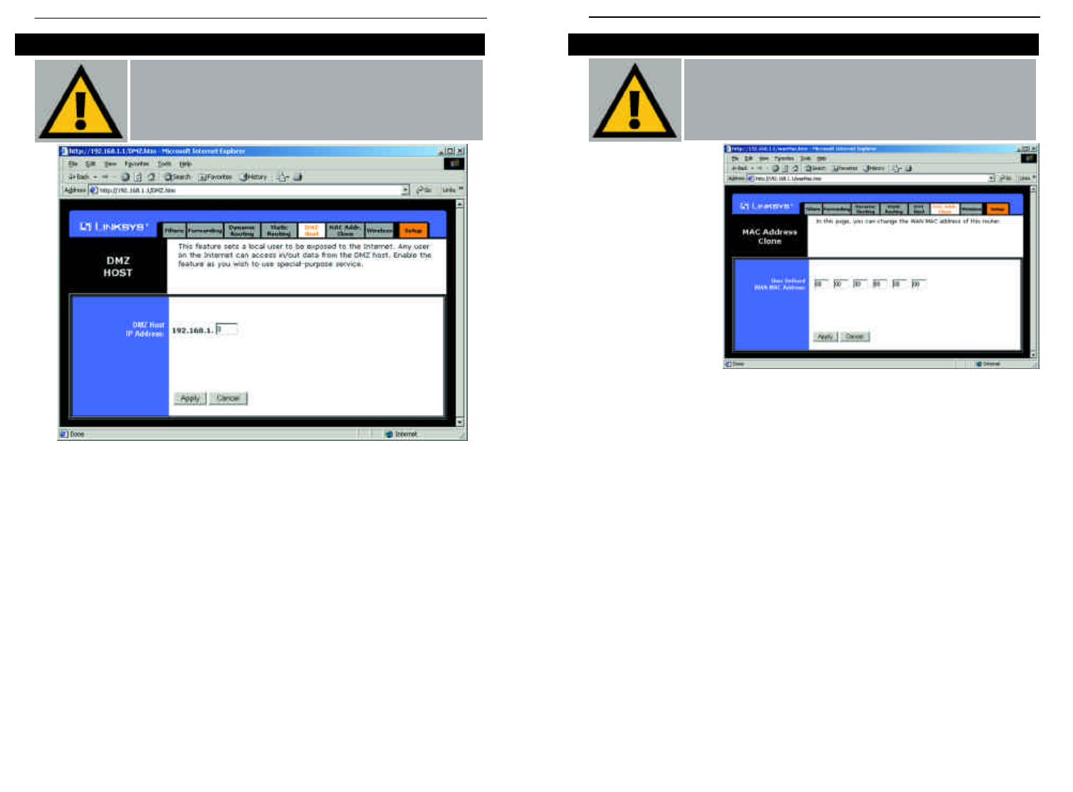
From the MAC
Address Cloning tab,
shown in Figure 5-22,
you can assign the
Router a MAC
address, which is a 12-
digit code assigned to
a unique piece of
hardware for identifi-
cation, like a social
security number.
Some ISPs require
that you register the
MAC address of your
network card/adapter, which was connected to your cable or DSL modem during
installation. Therefore, in order to connect the Router to your cable or DSL
modem in place of the PC (network card or adapter), you must change the Router
MAC to duplicate (or clone) your network card/adapter MAC. You can find your
adapter's MAC address by doing the following:
•If you are running Windows 95, 98 or Millennium:
Go to Start, Run, type in command, and press Enter. At the DOS prompt,
type winipcfg.
•If you are running Windows NT 4.0 or 2000:
Go to Start, Run, type in command, and press Enter. At the DOS prompt,
type ipconfig /all.
The Physical Address with 12 digits is your adapter’s MAC address. Enter
those 12 digits into the MAC Address fields, and click Apply. This “clones”
your network adapter’s MAC address onto the Router, and prevents you from
having to call your ISP to change the registered MAC address to the adapter’s
MAC address.
Advanced Tab: MAC Address Cloning
50
Important: MAC Address Cloning is an Advanced
Function. No changes should be made to this tab without a
thorough understanding of networking concepts.
Figure 5-22
The DMZ Hosting feature, accessed from the DMZ Host tab as shown in
Figure 5-21, allows one local user to be exposed to the Internet for use of a spe-
cial-purpose service such as Internet gaming and videoconferencing.
Whereas Port Range Forwarding can only forward a maximum of ten port
ranges, DMZ hosting forwards all the ports at the same time to one PC.
Before using this feature, the DHCP function on the PC whose port is being
exposed must be disabled and have a new static IP address assigned because its
IP address may change when using the DMZ function.
To expose one PC, enter the computer’s IP address. To get the IP address of a
computer, refer to Appendix D: Finding the MAC Address and IP Address for
Your Ethernet Adapter.
Deactivate DMZ by entering a zero in the field.
When finished, click the Applybutton to save the settings. Otherwise, click the
Cancel button to undo changes made on this screen.
Advanced Tab: DMZ Host
49
Important: DMZ Hosting is an Advanced Function. No
changes should be made to this tab without a thorough under-
standing of networking concepts.
Figure 5-21
Instant WirelessTM Series Wireless Access Point Router with 4-Port Switch
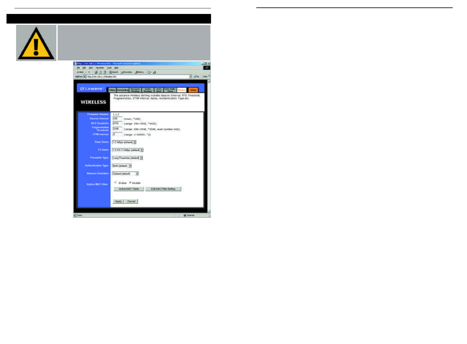
•Fragmentation Threshold. This value indicates how much of the Router’s
resources are devoted to recovering packet errors. The value should remain
at its default setting of 2,346. If you have decreased this value and experi-
ence high packet error rates, you can increase it again, but it will likely
decrease overall network performance. Only minor modifications of this
value are recommended.
•DTIM Interval. This value indicates the interval of the Delivery Traffic
Indication Message (DTIM). A DTIM field is a countdown field informing
clients of the next window for listening to broadcast and multicast mes-
sages. When the Router has buffered broadcast or multicast messages for
associated clients, it sends the next DTIM with a DTIM Interval value.
Clients for the Router hear the beacons and awaken to receive the broadcast
and multicast messages.
•Basic Rates. The basic transfer rates should be set depending on the speed
of your wireless network. You must select 1-2 (Mbps) if you have older
802.11 compliant equipment on your network, such as wireless adapters
that support only 1 or 2 Mbps. Selecting 1-2 (Mbps), however, does not
limit the basic transfer rates of faster adapters.
•TX Rates.Select all the supported rates at which an access point will com-
municate with a client.
•Preamble Type. The preamble defines the length of the CRC block for
communication between the Router and the roaming Network Card. (High
network traffic areas should use the shorter preamble type.) Select the
appropriate preamble type and click the Apply button to set it.
•Authentication Type. You may choose between Open System, Shared
Key, and Both. The Authentication Type default is set to Open System, in
which the sender and the recipient do NOT share a secret key. Each party
generates its own key-pair and asks the receiver to accept the randomly-
generated key. Once accepted, this key is used for a short time only. Then
a new key is generated and agreed upon. Shared Key is when both the
sender and the recipient share a secret key.
•Antenna Selection. This selection is for choosing which antenna transmits
data. By default, the Diversity Antenna selection, used to increase recep-
tion, is chosen.
52
Before making any
changes to the
Wireless tab, shown
in Figure 5-23,
please check the
wireless settings for
all your wireless
PCs, as these
changes will alter the
Router’s effective-
ness. In most cases,
these settings do not
need to be changed.
•Firmware Version. This indicates the Router’s firmware version.
•Beacon Interval. This value indicates the frequency interval of the beacon.
A beacon is a packet broadcast by the Router to keep the network synchro-
nized. A beacon includes the wireless LAN service area, the IP address, the
Broadcast destination addresses, a time stamp, Delivery Traffic Indicator
Maps, and the Traffic Indicator Message (TIM).
•RTS Threshold. This value should remain at its default setting of 2,346.
Should you encounter inconsistent data flow, only minor modifications are
recommended.
Advanced Tab: Wireless
51
Important: Wireless is an Advanced Function. No changes
should be made to this tab without a thorough understanding
of networking concepts.
Figure 5-23
Instant WirelessTM Series Wireless Access Point Router with 4-Port Switch
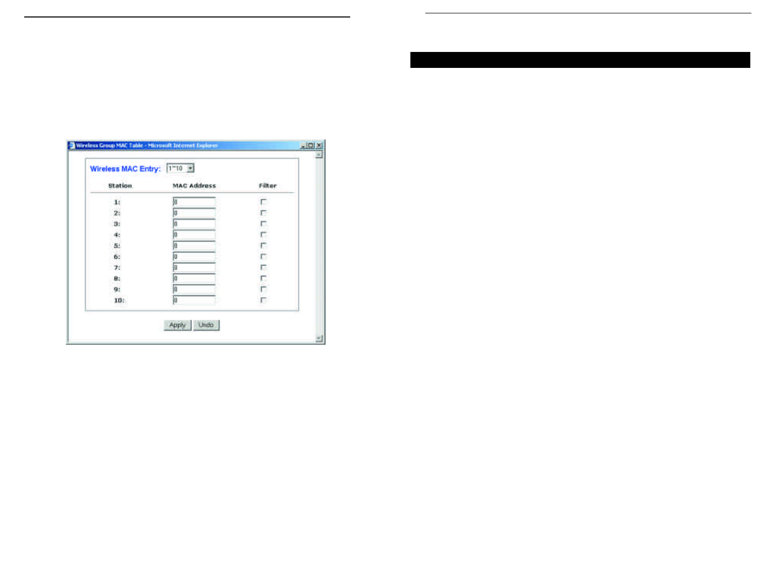
Appendix A:Troubleshooting
This appendix consists of two parts: “Common Problems and Solutions” and
“Frequently Asked Questions.” Provided are possible solutions to problems
regarding the installation and operation of the Router. If your situation is described
here, the problem should be solved by applying the corresponding solution. If you
can’t find an answer here, check the Linksys website at www.linksys.com.
1. I need to set a static IPaddress on a PC.
The Router, by default, assigns an IP address range of 192.168.1.100 to
192.168.1.150 using the DHCP server on the Router. To set a static IP address, you
can only use the ranges 192.168.1.2 to 192.168.1.99 and 192.168.1.151 to
192.168.1.254. Each PC or network device that uses TCP/IP must have a unique
address to identify itself in a network. If the IP address is not unique to a network,
Windows will generate an IP conflict error message. You can assign a static IP
address to a PC by performing the following steps:
For Windows 95, 98, and Me:
A. Click Start, Settings, and Control Panel. Double-click Network.
B. In The following network components are installed box, select the TCP/IP->
associated with your Ethernet adapter. If you only have one Ethernet adapter
installed, you will only see one TCP/IP line with no association to an Ethernet
adapter. Highlight it and click the Properties button.
C. In the TCP/IP properties window, select the IP addresstab, and select Specify
an IP address. Enter a unique IP address that is not used by any other com-
puter on the network connected to the Router. You can only use an IP address
in the ranges 192.168.1.2 to 192.168.1.99 and 192.168.1.151 to
192.168.1.254. Make sure that each IP address is unique for each PC or net-
work device.
D. Click the Gateway tab, and in the New Gateway prompt, enter 192.168.1.1,
which is the default IP address of the Router. Click the Add button to accept
the entry.
E. Click the DNS tab, and make sure the DNS Enabled option is selected. Enter
the Host and Domain names (e.g., John for Host and home for Domain).
Enter the DNS entry provided by your ISP. If your ISP has not provided the
DNS IP address, contact your ISP to get that information or go to its website
for the information.
F. Click the OK button in the TCP/IP properties window, and click Close or the
OK button for the Network window.
G. Restart the computer when asked.
53
Common Problems and Solutions
•Station MAC Filter. This option will allow you to prevent wireless users
on your network from accessing the Router’s functions.
Clicking the Active MAC Table button will display the MAC Addresses of
all users on your wireless network. Addresses in green show access to the
Router, while addresses in red do not have access.
To filter users, click the Edit MAC Filter Setting button. The window
shown in Figure 5-24 will appear.
Click the Wireless MAC Entry drop-down menu to select a range of
entries for your network. From within this range, select the entry for which
you’d like to manage access. Verify that the appropriate MAC Address is
entered into the MAC Address field. Click the Filter checkbox beside that
MAC Address. Now, this user will be prevented from accessing the Router.
All other users will have access. To allow only that user and deny access to
all others, leave Filter unchecked.
Click the Apply button to set these changes or Undo if you do not wish
these changes to go into effect.
When finished with the Wireless Tab, click the Apply button to save the set-
tings. Otherwise, click the Cancel button to undo changes made on this screen.
Figure 5-23
Instant WirelessTM Series Wireless Access Point Router with 4-Port Switch
54

For Windows XP:
The following instructions assume you are running Windows XP with the default
interface. If you are using the Classic interface (where the icons and menus look
like previous Windows versions), please follow the instructions for Windows 2000.
A. Click Start and Control Panel.
B. Click the Network and Internet Connections icon and then the Network
Connections icon.
C. Right-click the Local Area Connection that is associated with the Ethernet
adapter you are using, and select the Properties option.
D. In the This connection uses the following items box, highlight Internet
Protocol (TCP/IP). Click the Properties button.
E. Enter a unique IP address that is not used by any other computer on the net-
work connected to the Router. You can only use an IP address in the ranges
192.168.1.2 to 192.168.1.99 and 192.168.1.151 to 192.168.1.254.
F. Enter the Subnet Mask, 255.255.255.0.
G. Enter the Default Gateway, 192.168.1.1 (Router’s default IP address).
H. Toward the bottom of the window, select Use the following DNS server
addresses, and enter the Preferred DNS server and Alternative DNS server
(provided by your ISP). Contact your ISP or go on its website to find the infor-
mation.
I. Click the OK button in the Internet Protocol (TCP/IP) Properties window.
Click the OK button in the Local Area Connection Properties window.
2. I want to test my Internet connection.
A. Check your TCP/IP settings.
For Windows 95, 98, and Me:
Refer to your Ethernet adapter’s documentation for details. Make sure Obtain
IP address automatically is selected in the settings.
For Windows 2000:
• Click Start, Settings, and Control Panel. Double-click Network and Dial-
Up Connections.
• Right-click the Local Area Connectionthat is associated with the Ethernet
adapter you are using, and select the Properties option.
• In the Components checked are used by this connection box, highlight
Internet Protocol (TCP/IP), and click the Properties button. Make sure
that Obtain an IP address automatically and Obtain DNS server address
automatically are selected.
55
For Windows 2000:
A. Click Start, Settings, and Control Panel. Double-click Network and
Dial-Up Connections.
B. Right-click the Local Area Connectionthat is associated with the Ethernet
adapter you are using, and select the Properties option.
C. In the Components checked are used by this connection box, highlight
Internet Protocol (TCP/IP), and click the Properties button. Select Use
the following IP address option.
D. Enter a unique IP address that is not used by any other computer on the
network connected to the Router. You can only use an IP address in the
ranges 192.168.1.2 to 192.168.1.99 and 192.168.1.151 to 192.168.1.254.
E. Enter the Subnet Mask, 255.255.255.0.
F. Enter the Default Gateway, 192.168.1.1 (Router’s default IP address).
G. Toward the bottom of the window, select Use the following DNS server
addresses, and enter the Preferred DNS server and Alternative DNS
server (provided by your ISP). Contact your ISP or go on its website to find
the information.
H. Click the OK button in the Internet Protocol (TCP/IP) Properties window,
and click the OK button in the Local Area Connection Properties window.
I. Restart the computer if asked.
For Windows NT 4.0:
A. Click Start, Settings, and Control Panel. Double-click the Network icon.
B. Click the Protocol tab, and double-click TCP/IP Protocol.
C. When the window appears, make sure you have selected the correct
Adapter for your Ethernet adapter.
D. Select Specify an IP address, and enter a unique IP address that is not
used by any other computer on the network connected to the Router. You
can only use an IP address in the ranges 192.168.1.2 to 192.168.1.99 and
192.168.1.151 to 192.168.1.254.
E. Enter the Subnet Mask, 255.255.255.0.
F. Enter the Default Gateway, 192.168.1.1 (Router’s default IP address).
G. Click the DNS tab, and enter the Host and Domain names (e.g., John for
Host and home for Domain). Under DNS Service Search Order, click the
Add button. Enter the DNS IP address in the DNS Server field, and click
the Add button. Repeat this action for all DNS IP addresses given by your
ISP.
H. Click the OK button in the TCP/IP Protocol Properties window, and click
the Closebutton in the Network window.
I. Restart the computer if asked.
56
Instant WirelessTM Series Wireless Access Point Router with 4-Port Switch

C. In the command prompt, type ping 192.168.1.1 and press the Enter key.
• If you get a reply, the computer is communicating with the Router.
• If you do NOT get a reply, please check the cable, and make sure Obtain
an IP address automatically is selected in the TCP/IP settings for your
Ethernet adapter.
D. In the command prompt, type ping followed by your WAN IP address and
press the Enter key. The WAN IP Address can be found in the web inter-
face of the Router. For example, if your WAN IP address is 1.2.3.4, you
would enter ping 1.2.3.4 and press the Enter key.
• If you get a reply, the computer is connected to the Router.
• If you do NOT get a reply, try the ping command from a different com-
puter to verify that your original computer is not the cause of the prob-
lem.
E. In the command prompt, type ping www.yahoo.com and press the Enter
key.
• If you get a reply, the computer is connected to the Internet. If you can-
not open a webpage, try the ping command from a different computer to
verify that your original computer is not the cause of the problem.
• If you do NOT get a reply, there may be a problem with the connection.
Try the ping command from a different computer to verify that your orig-
inal computer is not the cause of the problem.
3. I am not getting an IP address on the WAN with my Internet connection.
A. Refer to “Problem #2, I want to test my Internet connection” to verify that
you have connectivity.
B. If you need to register the MAC address of your Ethernet adapter with your
ISP, please see “Appendix F: Finding the MAC address and IP Address for
Your Ethernet Adapter.” If you need to clone the MAC address of your
Ethernet adapter onto the Router, see the MAC Address Clone section of
“Chapter 5: Using the Router’s Web-based Utility” for details.
C. Make sure you are using the right WAN settings. Contact your ISP to see if
your WAN connection type is DHCP, Static IP Address, or PPPoE (com-
monly used by DSL consumers). Please refer to the Setup section of
“Chapter 5: Using the Router’s Web-based Utility” for details on WAN set-
tings.
D. Make sure you have the right cable. Check to see if the WAN column has a
solidly lit Link LED.
E. Make sure the cable connecting from your cable or DSL modem is con-
nected to the Router’s WAN port. Verify that the Status page of the Router’s
web interface shows a valid IP address from your ISP.
57
• Click the OK button in the Internet Protocol (TCP/IP) Properties win-
dow, and click the OK button in the Local Area Connection Properties
window.
• Restart the computer if asked.
For Windows XP:
The following instructions assume you are running Windows XP with the
default interface. If you are using the Classic interface (where the icons and
menus look like previous Windows versions), please follow the instructions
for Windows 2000.
• Click Start and Control Panel.
• Click the Network and Internet Connections icon and then the
Network Connections icon.• Right-click the Local Area Connection
that is associated with the Ethernet adapter you are using, and select the
Properties option.
• In the This connection uses the following items box, highlight Internet
Protocol (TCP/IP), and click the Properties button. Make sure that
Obtain an IP address automatically and Obtain DNS server address
automatically are selected.
• Click the OK button in the Internet Protocol (TCP/IP) Properties win-
dow, and click the OK button in the Local Area Connection Properties
window.
• Restart the computer if asked.
For Windows NT 4.0:
• Click Start, Settings, and Control Panel. Double-click the Network
icon.
• Click the Protocol tab, and double-click on TCP/IP Protocol.
• When the window appears, make sure you have selected the correct
Adapter for your Ethernet adapter and set it for Obtain an IP address
from a DHCP server.
• Click the OK button in the TCP/IP Protocol Properties window, and
click the Close button in the Network window.
• Restart the computer if asked.
B. Open a command prompt.
• For Windows 95, 98, and Me, please click Start and Run. In the Open
field, type in command. Press the Enter key or click the OK button.
• For Windows NT, 2000, and XP, please click Start and Run. In the
Open field, type cmd. Press the Enter key or click the OK button.
58
Instant WirelessTM Series Wireless Access Point Router with 4-Port Switch

F. Turn off the computer, Router, and cable/DSL modem. Wait 30 seconds,
and then turn on the Router, cable/DSL modem, and computer. Check the
Status tab of the Router’s web-based utility to see if you get an IP address.
4. I am not able to access the Router’s web interface Setup page.
A. Refer to “Problem #2, I want to test my Internet connection” to verify that
your computer is properly connected to the Router.
B. Refer to “Appendix D: Finding the MAC Address and IP address for Your
Ethernet Adapter” to verify that your computer has an IP Address, Subnet
Mask, Gateway, and DNS.
C. Set a static IP address on your system; refer to “Problem #1: I need to set a
static IP address.”
D. Refer to “Problem #10: I need to remove the proxy settings or the dial-up
pop-up window (for PPPoE users).”
5. I can’t get my Virtual Private Network (VPN) working through the Router.
Access the Router’s web interface by going to http://192.168.1.1 or the IP
address of the Router, and go to the Advanced => Filter tab. Make sure you
have IPsec pass-through and/or PPTP pass-through enabled.
VPNs that use IPSec with the ESP (Encapsulation Security Payload known as
protocol 50) authentication will work fine. At least one IPSec session will work
through the Router; however, simultaneous IPSec sessions may be possible,
depending on the specifics of your VPNs.
VPNs that use IPSec and AH (Authentication Header known as protocol 51)
are incompatible with the Router. AH has limitations due to occasional incom-
patibility with the NAT standard.
Change the IP address for the Router to another subnet to avoid a conflict
between the VPN IP address and your local IP address. For example, if your
VPN server assigns an IP address 192.168.1.X (X is a number from 1 to 254)
and your local LAN IP address is 192.168.1.X (X is the same number used in
the VPN IP address), the Router will have difficulties routing information to
the right location. If you change the Router’s IP address to 192.168.2.1, that
should solve the problem. Change the Router’s IP address through the Setup tab
of the web interface. If you assigned a static IP address to any computer or net-
work device on the network, you need to change its IP address accordingly to
192.168.2.Y (Y being any number from 1 to 254). Note that each IP address
must be unique within the network.
60
Your VPN may require port 500/UDP packets to be passed to the computer that
is connecting to the IPSec server. Refer to “Problem #7, I need to set up online
game hosting or use other Internet applications” for details.
Check the Linksys website for more information at www.linksys.com.
6. I need to set up a server behind my Router.
To use a server like a web, ftp, or mail server, you need to know the respective
port numbers they are using. For example, port 80 (HTTP) is used for web;
port 21 (FTP) is used for FTP, and port 25 (SMTP outgoing) and port 110
(POP3 incoming) are used for the mail server. You can get more information
by viewing the documentation provided with the server you installed. Follow
these steps to set up port forwarding through the Router’s web-based utility. We
will be setting up web, ftp, and mail servers.
A. Access the Router’s web-based utility by going to http://192.168.1.1 or the
IP address of the Router. Go to the Advanced => Forwarding tab.
B. Enter any name you want to use for the Customized Application.
C. Enter the Ext. Port range of the service you are using. For example, if you
have a web server, you would enter the range 80 to 80.
D. Check the protocol you will be using, TCP and/or UDP.
E. Enter the IP address of the PC or network device that you want the port
server to go to. For example, if the web server’s Ethernet adapter IP address
is 192.168.1.100, you would enter 100 in the field provided. Check
“Appendix D: Finding the MAC Address and IP Address for Your Ethernet
Adapter” for details on getting an IP address.
F. Check the Enable option for the port services you want to use. Consider the
example below:
Customized Ext. Port TCP UDP IP Address Enable
Application
Web server 80 to 80 X X192.168.1.100 X
FTP server 21 to 21 X192.168.1.101 X
SMTP (outgoing) 25 to 25 XX192.168.1.102 X
POP3 (incoming) 110 to 110 XX192.168.1.102 X
When you have completed the configuration, click the Apply button.
Instant WirelessTM Series Wireless Access Point Router with 4-Port Switch
59

7. I need to set up online game hosting or use other Internet applications.
If you want to play online games or use Internet applications, most will work
without doing any port forwarding or DMZ hosting. There may be cases when
you want to host an online game or Internet application. This would require
you to set up the Router to deliver incoming packets or data to a specific com-
puter. This also applies to the Internet applications you are using. The best way
to get the information on what port services to use is to go to the website of the
online game or application you want to use. Follow these steps to set up online
game hosting or use a certain Internet application:
A. Access the Router’s web interface by going to http://192.168.1.1 or the IP
addressof the Router. Go to the Advanced => Forwarding tab.
B. Enter any name you want to use for the Customized Application.
C. Enter the Ext. Port range of the service you are using. For example, if you
want to host Unreal Tournament (UT), you would enter the range 7777 to
27900.
D. Check the protocol you will be using, TCP and/or UDP.
E. Enter the IP address of the PC or network device that you want the port
server to go to. For example, if the web server’s Ethernet adapter IP address
is 192.168.1.100, you would enter 100 in the field provided. Check
“Appendix D: Finding the MAC Address and IP Address for Your Ethernet
Adapter” for details on getting an IP address.
F. Check the Enableoption for the port services you want to use. Consider the
example below:
Customized Ext. Port TCP UDP IP Address Enable
Application
UT 7777 to 27900 XX192.168.1.100 X
Halflife 27015 to 27015 XX192.168.1.105 X
PC Anywhere 5631 to 5631 X192.168.1.102 X
VPN IPSEC 500 to 500 X192.168.1.100 X
When you have completed the configuration, click the Apply button.
8. I can’t get the Internet game, server, or application to work.
If you are having difficulties getting any Internet game, server, or application
to function properly, consider exposing one PC to the Internet using
DeMilitarized Zone (DMZ) hosting. This option is available when an applica-
tion requires too many ports or when you are not sure which port services to
use. Make sure you disable all the forwarding entries if you want to success-
fully use DMZ hosting, since forwarding has priority over DMZ hosting. (In
other words, data that enters the Router will be checked first by the forwarding
settings. If the port number that the data enters from does not have port for-
warding, then the Router will send the data to whichever PC or network device
you set for DMZ hosting.) Follow these steps to set DMZ hosting:
A. Access the Router’s web-based utility by going to http://192.168.1.1 or the
IP address of the Router. Go to the Advanced => Forwarding tab.
B. Disable or remove the entries you have entered for forwarding. Keep this
information in case you want to use it at a later time.
C. Click the DMZ Host tab.
D. Enter the Ethernet adapter’s IP address of the computer you want exposed
to the Internet. This will bypass the NAT firewall for that computer. Please
refer to “Appendix D: Finding the MAC Address and IP Address for Your
Ethernet Adapter” for details on getting an IP address.
Once completed with the configuration, click the Apply button.
9. I forgot my password, or the password prompt always appears when saving set-
tings to the Router.
Reset the Router to factory default by pressing the Reset button for 30 seconds
and then releasing it. If you are still getting prompted for a password when sav-
ing settings, then perform the following steps:
A. Access the Router’s web interface by going to http://192.168.1.1 or the IP
address of the Router. Enter the default password admin, and click the
Password tab.
B. Enter a different password in the Router Password field, and enter the
same password in the second field to confirm the password.
C. Click the Apply button.
Instant WirelessTM Series Wireless Access Point Router with 4-Port Switch
61 62

13. The firmware upgrade failed, and/or the Diag LED is flashing.
The upgrade could have failed for a number of reasons. Follow these steps to
upgrade the firmware and/or make the Diag LED stop flashing:
A. If the firmware upgrade failed, use the TFTP program (it was downloaded
along with the firmware). Open the pdf that was downloaded along with the
firmware and TFTP program, and follow the pdf’s instructions.
B. Set a static IP address on the PC; refer to “Problem #1, I need to set a stat-
ic IP address.” Use the following IP address settings for the computer you
are using:
IP Address: 192.168.1.50
Subnet Mask: 255.255.255.0
Gateway: 192.168.1.1
C. Perform the upgrade using the TFTP program or the Router’s web-based
utility through its Help tab.
14. My DSL service’s PPPoE is always disconnecting.
PPPoE is not actually a dedicated or always-on connection. The DSL ISP can
disconnect the service after a period of inactivity, just like a normal phone dial-
up connection to the Internet. There is a setup option to “keep alive” the con-
nection. This may not always work, so you may need to re-establish connec-
tion periodically.
A. To connect to the Router, go to the web browser, and enter
http://192.168.1.1 or the IP address of the Router.
B. Enter the password, if asked. (The default password is admin.)
C. In the Setup tab, select the option Keep Alive, and set the Redial Period
option at 20 (seconds).
D. Click the Apply button.
E. Click the Status tab, and click the Connect button.
F. You may see the login status display as Connecting. Press the F5 key to
refresh the screen, until you see the login status display as Connected.
G. Click the Apply button to continue.
If the connection is lost again, follow steps E to G to re-establish connection.
10. I am a PPPoE user, and I need to remove the proxy settings or the dial-up pop-
up window.
If you have proxy settings, you need to disable these on your computer.
Because the Router is the gateway for the Internet connection, the computer
does not need any proxy settings to gain access. Please follow these directions
to verify that you do not have any proxy settings and that the browser you use
is set to connect directly to the LAN.
For Microsoft Internet Explorer 5.0 or higher:
A. Click Start, Settings, and Control Panel. Double-click Internet Options.
B. Click the Connections tab.
C. Click the LAN settingsbutton and remove anything that is checked.
D. Click the OK button to go back to the previous screen.
E. Click the option Never dial a connection. This will remove any dial-up
pop-ups for PPPoE users.
For Netscape 4.7 or higher:
A. Start Netscape Navigator, and click Edit, Preferences, Advanced, and
Proxies.
B. Make sure you have Direct connection to the Internet selected on this
screen.
C. Close all the windows to finish.
11. To start over, I need to set the Router to factory default.
Hold the Reset button for up to 30 seconds and then release it. This will return
the password, forwarding, and other settings on the Router to the factory
default settings. In other words, the Router will revert to its original factory
configuration.
12. I need to upgrade the firmware.
In order to upgrade the firmware with the latest features, you need to go to the
Linksys website and download the latest firmware at www.linksys.com. Follow
these steps:
A. Go to the Linksys website at http://www.linksys.com and download the
latest firmware.
B. To upgrade the firmware, follow the steps in the Help section found in
“Chapter 5: Using the Router’s Web-based Utility.”
Instant WirelessTM Series Wireless Access Point Router with 4-Port Switch
63 64

17. The Diag LED stays lit continuously.
• The Diag LED lights up when the device is first powered up. Meantime,
the system will boot up itself and check for proper operation. After fin-
ishing the checking procedure, the LED turns off to show that the system
is working fine. If the LED remains lit after this time, the device is not
working properly. Try to flash the firmware by assigning a static IP
address to the computer, and then upgrade the firmware. Try using the
following settings, IP Address: 192.168.1.50 and Subnet Mask:
255.255.255.0.
18. When I enter a URL or IP address, I get a time-out error or am prompted to retry.
• Check if other PCs work. If they do, ensure that your workstation’s IP set-
tings are correct (IP Address, Subnet Mask, Default Gateway, and DNS).
Restart the computer that is having a problem.
• If the PCs are configured correctly, but still not working, check the
Router. Ensure that it is connected and ON. Connect to it and check its
settings. (If you cannot connect to it, check the LAN and power connec-
tions.)
• If the Router is configured correctly, check your Internet connection
(DSL/cable modem, etc.) to see if it is working correctly. You can remove
the Router to verify a direct connection.
• Manually configure the TCP/IP with a DNS address provided by your
ISP.
• Make sure that your browser is set to connect directly and that any dial-
up is disabled. For Internet Explorer, click Tools, Internet Options, and
then the Connection tab. Make sure that Internet Explorer is set to Never
dial a connection. For Netscape Navigator, click Edit, Preferences,
Advanced, and Proxy. Make sure that Netscape Navigator is set to
Direct connection to the Internet.
19. The Full/Col LED keeps flickering continuously.
• Check the Category 5 Ethernet cable and its RJ-45 connectors.
• There may be interference with other network devices. Try removing
other PCs or network devices to see if the problem persists. Eliminate
each network device one at a time to determine the cause.
15. I can't access my email, web, or VPN, or I am getting corrupted data from the
Internet.
The Maximum Transmission Unit (MTU) setting may need to be adjusted. By
default, the MTU is set at 1500. For most DSL users, it is strongly recom-
mended to use MTU 1492. If you are having some difficulties, perform the fol-
lowing steps:
A. To connect to the Router, go to the web browser, and enter
http://192.168.1.1 or the IP address of the Router.
B. Enter the password, if asked. (The default password is admin.)
C. Click the Advanced => Filter tab.
D. Look for the MTU option, and select Enable. In the Size field, enter 1492.
E. Click the Apply button to continue.
If your difficulties continue, change the Size to different values. Try this list of
values, one value at a time, in this order, until your problem is solved:
1462
1400
1362
1300
16. I need to use port triggering.
Port triggering looks at the outgoing port services used and will trigger the
Router to open a specific port, depending on which port an Internet application
uses. Follow these steps:
A. To connect to the Router, go to the web browser, and enter
http://192.168.1.1 or the IP address of the Router.
B. Enter the password, if asked. (The default password is admin.)
C. Click the Advanced => Forwarding tab, and click the Port Trigger button.
D. Enter any name you want to use for the Application Name.
E. Enter the Triggered Port Range. Check with your Internet application
provider for more information on which outgoing port services it is using.
F. Enter the Incoming Port Range. Check with your Internet Application
provider for more information on which incoming port services are
required by the Internet application.
Instant WirelessTM Series Wireless Access Point Router with 4-Port Switch
65 66

What is the maximum number of IP addresses that the Router will support? The
Router will support up to 253 IP addresses.
Is IPSec Pass-Through supported by the Router? Yes, it is a built-in feature that
the Router automatically enables.
Where is the Router installed on the network? In a typical environment, the
Router is installed between the cable/DSL modem and the LAN. Plug the
Router into the cable/DSL modem’s Ethernet port.
Does the Router support IPX or AppleTalk? No. TCP/IP is the only protocol stan-
dard for the Internet and has become the global standard for communications.
IPX, a NetWare communications protocol used only to route messages from
one node to another, and AppleTalk, a communications protocol used on
Apple and Macintosh networks, can be used for LAN to LAN connections,
but those protocols cannot connect from WAN to LAN.
Does the WAN connection of the Router support 100 Mbps Ethernet? Because of
the speed limitations of broadband Internet connections, the Router’s current
hardware design supports 10 Mbps Ethernet on its WAN port. It does, of
course, support 100 Mbps over the auto-sensing Fast Ethernet 10/100 switch
on the LAN side of the Router.
What is Network Address Translation and what is it used for? Network Address
Translation (NAT) translates multiple IP addresses on the private LAN to one
public address that is sent out to the Internet. This adds a level of security
since the address of a PC connected to the private LAN is never transmitted
on the Internet. Furthermore, NAT allows the Router to be used with low cost
Internet accounts, such as DSL or cable modems, when only one TCP/IP
address is provided by the ISP. The user may have many private addresses
behind this single address provided by the ISP.
Does the Router support any operating system other than Windows 95, Windows
98, Windows 2000, Windows NT, or Windows XP? Yes, but Linksys does not, at
this time, provide technical support for setup, configuration or troubleshoot-
ing of any non-Windows operating systems.
Frequently Asked Questions Does the Router support ICQ send file? Yes, with the following fix: click ICQ
menu -> preference -> connections tab->, and check I am behind a fire-
wall or proxy. Then set the firewall time-out to 80 seconds in the firewall set-
ting. The Internet user can then send a file to a user behind the Router.
I set up an Unreal Tournament Server, but others on the LAN cannot join. What do
I need to do? If you have a dedicated Unreal Tournament server running, you
need to create a static IP for each of the LAN computers and forward ports
7777, 7778, 7779, 7780, 7781, and 27900 to the IP address of the server. You
can also use a port forwarding range of 7777 ~ 27900. If you want to use the
UT Server Admin, forward another port (8080 usually works well but is used
for remote admin. You may have to disable this.), and then in the
[UWeb.WebServer] section of the server.ini file, set the ListenPort to 8080 (to
match the mapped port above) and ServerName to the IP assigned to the
Router from your ISP.
Can multiple gamers on the LAN get on one game server and play simultaneously
with just one public IP address? It depends on which network game or what
kind of game server you are using. For example, Unreal Tournament supports
multi-login with one public IP.
How do I get Half-Life: Team Fortress to work with the Router? The default client
port for Half-Life is 27005. The computers on your LAN need to have
“+clientport 2700x” added to the HL shortcut command line; the x would be
6, 7, 8, and on up. This lets multiple computers connect to the same server.
One problem: Version 1.0.1.6 won’t let multiple computers with the same CD
key connect at the same time, even if on the same LAN (not a problem with
1.0.1.3). As far as hosting games, the HL server does not need to be in the
DMZ. Just forward port 27015 to the local IP address of the server comput-
er.
How can I block corrupted FTP downloads? If you are experiencing corrupted
files when you download a file with your FTP client, try using another FTP
program.
The web page hangs; downloads are corrupt, or nothing but junk characters are
being displayed on the screen. What do I need to do? Force your Ethernet
adapter to 10Mbps or half duplex mode, and turn off the “Auto-negotiate”
feature of your Ethernet adapter as a temporary measure. (Please look at the
Network Control Panel in your Ethernet adapter’s Advanced Properties tab.)
Instant WirelessTM Series Wireless Access Point Router with 4-Port Switch
67 68

Make sure that your proxy setting is disabled in the browser. Check our web-
site at www.linksys.com for more information.
If all else fails in the installation, what can I do? Reset the Router by holding
down the reset button until the Diag LED fully turns on and off. Reset your
cable or DSL modem by powering the unit off and then on. Obtain and flash
the latest firmware release that is readily available on the Linksys website,
www.linksys.com.
How will I be notified of new Router firmware upgrades? All Linksys firmware
upgrades are posted on the Linksys website at www.linksys.com, where they
can be downloaded for free. The Router’s firmware can be upgraded with
TFTP programs. If the Router’s Internet connection is working well, there is
no need to download a newer firmware version, unless that version contains
new features that you would like to use. Downloading a more current version
of Router firmware will not enhance the quality or speed of your Internet con-
nection, and may disrupt your current connection stability.
Will the Router function in a Macintosh environment? Yes, but the Router’s setup
pages are accessible only through Internet Explorer 4.0 or Netscape
Navigator 4.0 or higher for Macintosh.
I am not able to get the web configuration screen for the Router. What can I do?
You may have to remove the proxy settings on your Internet browser, e.g.,
Netscape Navigator or Internet Explorer. Or remove the dial-up settings on
your browser. Check with your browser documentation, and make sure that
your browser is set to connect directly and that any dial-up is disabled. Make
sure that your browser is set to connect directly and that any dial-up is dis -
abled. For Internet Explorer, click Tools , Internet Options, and then the
Connection tab. Make sure that Internet Explorer is set to Never dial a con-
nection. For Netscape Navigator, click Edit, Preferences, Advanced, and
Proxy. Make sure that Netscape Navigator is set to Direct connection to the
Internet.
What is DMZ Hosting? Demilitarized Zone (DMZ) allows one IP address (com-
puter) to be exposed to the Internet. Some applications require multiple
TCP/IP ports to be open. It is recommended that you set your computer with
a static IP if you want to use DMZ Hosting. To get the LAN IP address, see
“Appendix D: Finding the MAC Address and IP Address for Your Ethernet
Adapter.”
If DMZ Hosting is used, does the exposed user share the public IP with the Router?
No.
Does the Router pass PPTP packets or actively route PPTP sessions? The Router
allows PPTP packets to pass through.
Is the Router cross-platform compatible? Any platform that supports Ethernet
and TCP/IP is compatible with the Router.
How many ports can be simultaneously forwarded? Theoretically, the Router can
establish 520 sessions at the same time, but you can only forward 10 ranges
of ports.
Does the Router replace a modem? Is there a cable or DSL modem in the Router?
No, this version of the Router must work in conjunction with a cable or DSL
modem.
Which modems are compatible with the Router? The Router is compatible with
virtually any cable or DSL modem that supports Ethernet.
What are the advanced features of the Router? The Router’s advanced features
include IP Filtering, Port Range Forwarding, Dynamic Routing, Static
Routing, DMZ hosting, and MAC Address Cloning.
What is the maximum number of VPN sessions allowed by the Router?
The maximum number depends on many factors. At least one IPSec session
will work through the Router; however, simultaneous IPSec sessions may be
possible, depending on the specifics of your VPNs.
How big is the memory buffer on the Router? 1MB buffer and 512KB flash.
How can I check whether I have static or DHCP IP Addresses? Consult your ISP
to obtain this information.
How do I get mIRC to work with the Router? Under the Port Range Forwarding
tab, set port forwarding to 113 for the PC on which you are using mIRC.
Can the Router act as my DHCP Server? Yes. The Router has DHCP Server soft-
ware built-in.
Can I run an application from a remote computer over the wireless network? This
will depend on whether or not the application is designed to be used over a
Instant WirelessTM Series Wireless Access Point Router with 4-Port Switch
69 70

network. Consult the application’s documentation to determine if it supports
operation over a network.
What is the IEEE 802.11b standard? The IEEE 802.11b Wireless LAN standards
subcommittee formulates the standard for the industry. The objective is to
enable wireless LAN hardware from different manufacturers to communicate.
What IEEE 802.11 features are supported? The product supports the following
IEEE 802.11 functions:
• CSMA/CA plus Acknowledge protocol
• Multi-Channel Roaming
• Automatic Rate Selection
• RTS/CTS feature
• Fragmentation
• Power Management
What is BSS ID? A specific Ad-hoc LAN is called a Basic Service Set (BSS).
Computers in a BSS must be configured with the same BSS ID.
What is SSID? An Infrastructure configuration could also support roaming
capability for mobile workers. More than one BSS can be configured as an
Extended Service Set (ESS). Users within an ESS could roam freely between
BSSs while maintaining a continuous connection to the wireless network sta-
tions and Access Points.
What is ISM band? The FCC and their counterparts outside of the U.S. have set
aside bandwidth for unlicensed use in the ISM (Industrial, Scientific and
Medical) band. This presents a truly revolutionary opportunity to place con-
venient high speed wireless capabilities in the hands of users around the
globe.
What is Spread Spectrum? Spread Spectrum technology is a wideband radio
frequency technique developed by the military for use in reliable, secure, mis -
sion-critical communications systems. It is designed to trade off bandwidth
efficiency for reliability, integrity, and security. In other words, more band-
width is consumed than in the case of narrowband transmission, but the trade-
off produces a signal that is, in effect, louder and thus easier to detect, pro-
vided that the receiver knows the parameters of the spread-spectrum signal
being broadcast. If a receiver is not tuned to the right frequency, a spread-
spectrum signal looks like background noise. There are two main alternatives,
Direct Sequence Spread Spectrum (DSSS) and Frequency Hopping Spread
Spectrum (FHSS).
What is DSSS? What is FHSS? And what are their differences? Frequency
Hopping Spread Spectrum (FHSS) uses a narrowband carrier that changes
frequency in a pattern that is known to both transmitter and receiver. Properly
synchronized, the net effect is to maintain a single logical channel. To an
unintended receiver, FHSS appears to be short-duration impulse noise. Direct
Sequence Spread Spectrum (DSSS) generates a redundant bit pattern for each
bit to be transmitted. This bit pattern is called a chip (or chipping code). The
longer the chip, the greater the probability that the original data can be recov-
ered. Even if one or more bits in the chip are damaged during transmission,
statistical techniques embedded in the radio can recover the original data
without the need for retransmission. To an unintended receiver, DSSS appears
as low power wideband noise and is rejected (ignored) by most narrowband
receivers.
Would the information be intercepted while transmitting on air? WLAN features
two-fold protection in security. On the hardware side, as with Direct
Sequence Spread Spectrum technology, it has the inherent security feature of
scrambling. On the software side, the WLAN series offers the encryption
function (WEP) to enhance security and access control. Users can set it up
depending upon their needs.
What is WEP? WEP is Wired Equivalent Privacy, a data privacy mechanism
based on a 40/64 bit shared key algorithm, as described in the IEEE 802.11
standard.
What is a MAC Address? The Media Access Control (MAC) address is a unique
number assigned by the manufacturer to any Ethernet networking device,
such as a network adapter, that allows the network to identify it at the hard-
ware level. For all practical purposes, this number is usually permanent.
Unlike IP addresses, which can change every time a computer logs on to the
network, the MAC address of a device stays the same, making it a valuable
identifier for the network.
If your questions are not addressed here, refer to the Linksys website,
www.linksys.com.
Instant WirelessTM Series Wireless Access Point Router with 4-Port Switch
71 72

3. At the DOS command prompt, type “ping mail” (assuming that the loca-
tion for which you’re trying to find an IP address is configured as “mail”).
Press Enter. Information such as the following data, taken from a ping of
Microsoft Network’s e-mail server, will be displayed.
4. Write down the IP address returned by the ping command. (In the
example above: 24.53.32.4.) This IP address is the actual IP address of the
server “mail,” or any other word or value you have pinged.
Step Two: Pinging for a Web Address
While the IP address returned above would work as your e-mail server address,
it may not be permanent. IP addresses change all the time. Web addresses, how-
ever, usually don’t. Because of this, you’re likely to have fewer problems by
configuring your system with web addresses rather than IP addresses. Follow
the instructions below to find the web address assigned to the IP address you
just pinged.
1. At the DOS command prompt, type “ping -a 24.53.32.4,” where
24.53.32.4 is the IP address you just pinged. Information such as the fol-
lowing data will be displayed.
C:\>ping mail
Pinging mail [24.53.32.4] with 32 bytes of data:
Reply from 24.53.32.4: bytes=32 time<10ms TTL=128
Reply from 24.53.32.4: bytes=32 time<10ms TTL=128
Reply from 24.53.32.4: bytes=32 time<10ms TTL=128
Reply from 24.53.32.4: bytes=32 time<10ms TTL=128
Ping statistics for 24.53.32.4:
Packets: Sent = 4, Received = 4, Lost = 0 (0%
loss),
Approximate round trip times in milli-seconds:
Minimum = 0ms, Maximum = 0ms, Average = 0ms
74
Appendix B: How to Ping Your ISP’s
E-mail and Web Addresses
Virtually all Internet addresses are configured with words or characters (i.e.,
www.linksys.com, www.yahoo.com, etc.) In actuality, however, these Internet
addresses are assigned to IP addresses, which are the true addresses on the
Internet. For example, www.linksys.com is actually 216.23.162.142. Entering
that into your web browser will bring up at the Linksys home page every time.
IP and web addresses, however, can sometimes be long and hard to remember.
Because of this, certain ISPs will shorten their server addresses to single words
or codes on their users’ web browser or e-mail configurations. If your ISP’s e-
mail and web server addresses are configured with single words (“www,” “e-
mail,” “home,” “pop3,” etc.) rather than whole Internet Addresses or IP
Addresses, the Router may have problems sending or receiving mail and
accessing the Internet. This happens because the Router has not been config-
ured by your ISP to accept their abbreviated server addresses.
The solution is to determine the true web addresses behind your ISP’s code
words. You can determine the IP and web addresses of your ISP’s servers by
“pinging” them.
Step One: Pinging an IP Address
The first step to determining your ISP’s web and e-mail server address is to
ping its IP address.
1. Power on the computer and the cable or DSL modem, and restore the
network configuration set by your ISP if you have since changed it.
2. Click Start, then Run, and type “command.” This will bring up the DOS
window.
73
Note: If you don’t have your ISP’s web and e-mail IP addresses, you must
either get them from your ISP or follow these steps prior to connecting the
Router to your network.
Instant WirelessTM Series Wireless Access Point Router with 4-Port Switch
Appendix C: Configuring Wireless
Security
An acronym for Wired Equivalent Privacy, WEP is an encryption method used
to protect your wireless data communications. WEP uses a combination of 64-
bit or 128-bit keys to provide access control to your network and encryption
security for every data transmission. To decode a data transmission, each point
in a network must use an identical 64-bit or 128-bit key. Higher encryption lev-
els mean higher levels of security, but due to the complexity of the encryption,
they may mean decreased network performance.
You may also have heard the term “40-bit” used in conjunction with WEP
encryption. This is simply another term for 64-bit WEP encryption. This level
of WEP encryption has been called 40-bit because it uses a 40-bit secret key
along with a 24-bit Initialization Vector (40 + 24 = 64). Wireless vendors may
use either name. Linksys uses the term “64-bit” when referring to this level of
encryption.
Make sure your wireless network is functioning before attempting to configure
WEP encryption.
A 128-bit WEP encrypted wireless network will NOT communicate with a 64-
bit WEP encrypted wireless network. Therefore, make sure that all of your
wireless devices are using the same encryption level. All wireless devices com-
plying with the 802.11b standard will support 64-bit WEP.
In addition to enabling WEP, Linksys also recommends the following security
implementations:
•Changing the SSID from the default “linksys”
•Changing the WEP key regularly
Note: WEP encryption is an additional data securi-
ty measure and not essential for router operation.
Note: In order for WEP Encryption to be enabled, wireless functions must
first be enabled. Select Enable under the Wireless section before proceeding.
2. Write down the web address returned by the ping command (in the
example above: mail.msnv3.occa.home.com.). This web address is the web
address assigned to the IP address you just pinged. While the IP address of
“mail” could conceivably change, it is likely that this web address will not.
3. Replace your ISP’s abbreviated server address with this extended web
address in the corresponding Internet application (web browser, e-mail
application, etc.).
Once you have replaced the brief server address with the true server address,
the Router should have no problem accessing the Internet through that Internet
application.
C:\>ping -a 24.53.32.4
Pinging mail.msnv3.occa.home.com [24.53.32.4] with
32 bytes of data:
Reply from 24.53.32.4: bytes=32 time<10ms TTL=127
Reply from 24.53.32.4: bytes=32 time<10ms TTL=127
Reply from 24.53.32.4: bytes=32 time<10ms TTL=127
Reply from 24.53.32.4: bytes=32 time<10ms TTL=127
Ping statistics for 24.53.32.4:
Packets: Sent = 4, Received = 4, Lost = 0 (0%
loss),
Approximate round trip times in milli-seconds:
Minimum = 0ms, Maximum = 0ms, Average = 0ms
75
Instant WirelessTM Series Wireless Access Point Router with 4-Port Switch
76
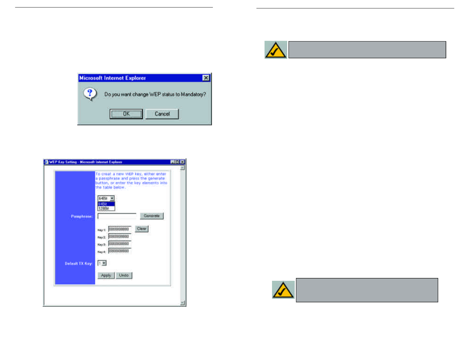
•WEP (64Bit or 128B) Select the level of encryption from the drop-down
box. 128-bit WEP encryption is unique to Linksys and may conflict with
other vendors’ WEP encryption.
The WEP Encryption key is generated in one of two ways:
1. You may create an encryption key by using a Passphrase.
a. Enter a Passphrase, a user-defined password, into the Passphrase field.
The Passphrase can be a maximum of 31 letters, symbols, and numbers.
No spaces can be used.
b. Click the Generate button to create a key. The key will be 10 digits if
you chose 64-bit encryption, or 26 digits if you chose 128-bit encryption.
This key will be used to encrypt and decrypt the data being sent between
the Router and your network’s wireless PCs.
The Key field may not display all digits. Using the mouse, click any-
where within the Key field. Move the cursor to the right to view the rest
of the Key. Make sure your write down the entire Key EXACTLY the
way it is displayed.
2. You may enter the encryption key manually.
Make a note of the Passphrase or Manual Key. You will need it for the other
wireless devices on the network, as the same WEP encryption key must be
entered in all wireless devices on the network.
Once you have chosen your key encryption method and entered either the
Passphrase or manual key, click the Apply button, and the encryption portion
of the setup is complete.
Note: In order to utilize WEP encryption, all points in your wireless
network must have WEP enabled and be set to the same Key Setting.
Note: In Windows XP, a 128-bit Key generated by the Router
will be called a "104 bits (26 digits)" key, and a 64-bit Key gen-
erated by the Router will be called a “40 bits (10 digits)” key.
The following steps will show you how to utilize WEP encryption
1. From the Web-based Utility’s Setup tab, select Mandatory under the WEP
section.
2. Press the WEP Key Setting button to set the WEP Encryption type and
level.
3. The screen dis-
played in Figure
C-1 may appear,
verifying that you
are enabling WEP
Encryption. Press
the OK button to
continue.
4. This will display the screen shown in Figure C-2. From this screen, you will
choose your WEP Encryption settings.
Figure C-2
Figure C-1
Instant WirelessTM Series Wireless Access Point Router with 4-Port Switch
77 78
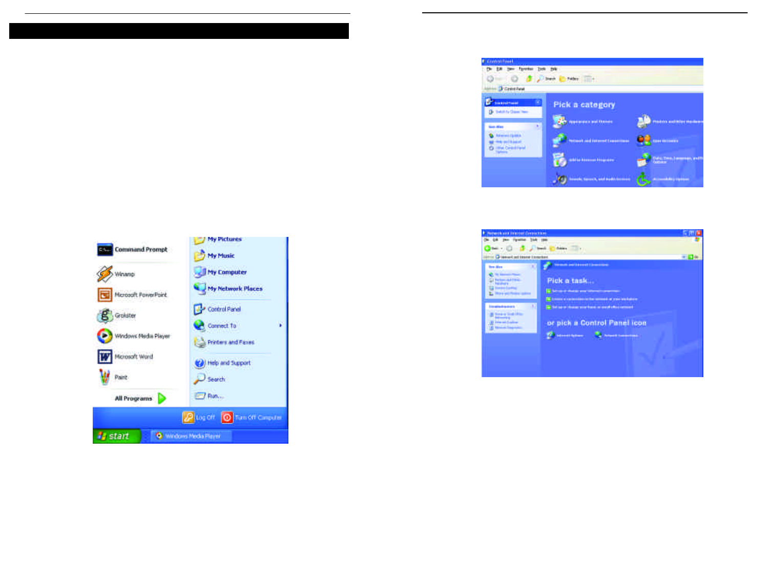
2. In the “Control Panel” window, click the Network and Internet
Connections icon, shown in Figure C-4.
3. Click the Network Connections icon, shown in Figure C-5.
4. The “Network Connections” window will appear, as shown in Figure C-6.
Under LAN or High-Speed Internet you will see all Network cards that are
installed and operating in your computer. Double-click the Wireless
Network Connection icon associated with your wireless adapter.
If the “Wireless Network Connection Status” window appears, continue to
the next step
Figure C-4
Figure C-5
As Windows XP does not allow for the use of the Linksys Passphrase feature
with the wireless PC adapters, you will need to manually enter the key gener-
ated in the previous section.
The following steps will help you enable WEP and enter the encryption key
manually for your wireless PC cards, in order to enable your Windows XP sys-
tem to communicate with the Router wirelessly.
These steps assume that your CD-ROM drive is letter D and that you are run-
ning Windows XP in the default mode.
Be sure you have the WEP Key generated by the Router.
1. As shown in Figure C-3, click the Startbutton and go to the Control Panel.
Figure C-3
Configuring Wireless Security in Windows XP
Instant WirelessTM Series Wireless Access Point Router with 4-Port Switch
79 80
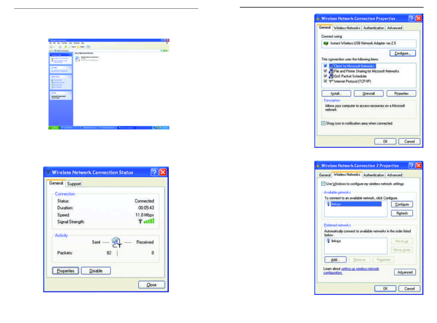
6. When the “Wireless
Network Connection
Properties” window
appears, as in Figure C-
8, click the Wireless
Networks Tab.
7. If the appropriate wire-
less network, specified
by the Router’s SSID, is
displayed in the
“Preferred networks”
section, as shown in
Figure C-9, double-
click it and continue to
the next step.
Otherwise, click on the
appropriate wireless
network, specified by
the Router’s SSID, in
the “Available net-
works” section. Then,
click the Configure
button
Figure C-8
Figure C-9
If a “Connect to Wireless Network” window appears, in the Available
Networks section, click the desired wireless network, specified by the
Router’s SSID. Then, double-click the Wireless Network Connection icon.
5. When the “Wireless Network Connection Status” window appears, as in
Figure C-7, click the Properties button.
Figure C-6
Figure C-7
Instant WirelessTM Series Wireless Access Point Router with 4-Port Switch
81 82
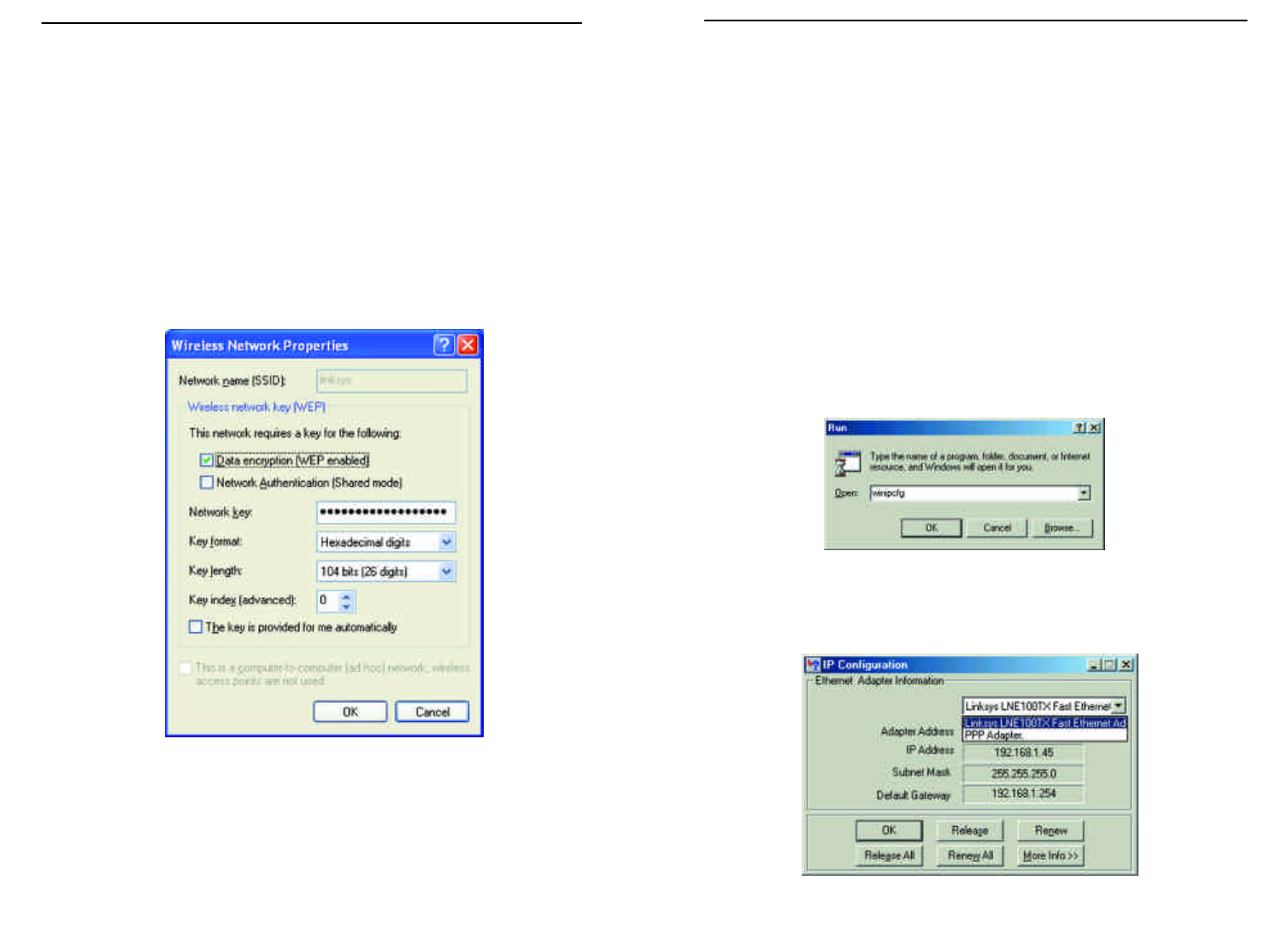
Appendix D: Finding the MAC
Address and IPAddress for Your
Ethernet Adapter
This section describes how to find the MAC address for your Ethernet adapter
to do either MAC Filtering or MAC Address Cloning for the Router and ISP.
You can also find the IP address of your computer’s Ethernet adapter. The IP
address is used for filtering, forwarding, and DMZ. Follow these steps to find
the MAC address or IP address for your adapter in Windows 95, 98, ME, NT,
2000, and XP.
For Windows 95, 98, and ME:
1. Click on Start and Run. In the Open field, enter winipcfg, as shown in
Figure D-1. Then press the Enter key or the OK button.
2. When the IP Configuration window appears, as shown in Figure D-2, select
the Ethernet adapter you are using to connect to the Router via a CAT 5
Ethernet cable.
Figure D-1
Figure D-2
8. The “Wireless Network Properties” window (shown in Figure C-10) will
appear.
Click the check box for the Data encryption (WEP enabled) option.
Remove the check from the Network Authentication (Shared mode) and
The key is provided for me automatically fields.
In the "Network key" field, enter the exact Key (all 10 or 26 digits, depend-
ing on the level of encryption) generated by the Router.
Verify that the “Key format” field displays “Hexadecimal digits” and that
the “Key length” field displays either “40 bits (10 digits)” or “104 bits (26
digits)”. If this is not displayed, you have entered the key incorrectly.
Click the OK button to save the settings. Click on OK buttons until you
get back to the “Wireless Network Connection Status” window. Close any
open windows to get back to the Windows XP desktop.
Close any applications and reboot your PC. After reboot, WEP configuration
is complete and you should be able to connect wirelessly to the Router.
Figure C-10
Instant WirelessTM Series Wireless Access Point Router with 4-Port Switch
83 84
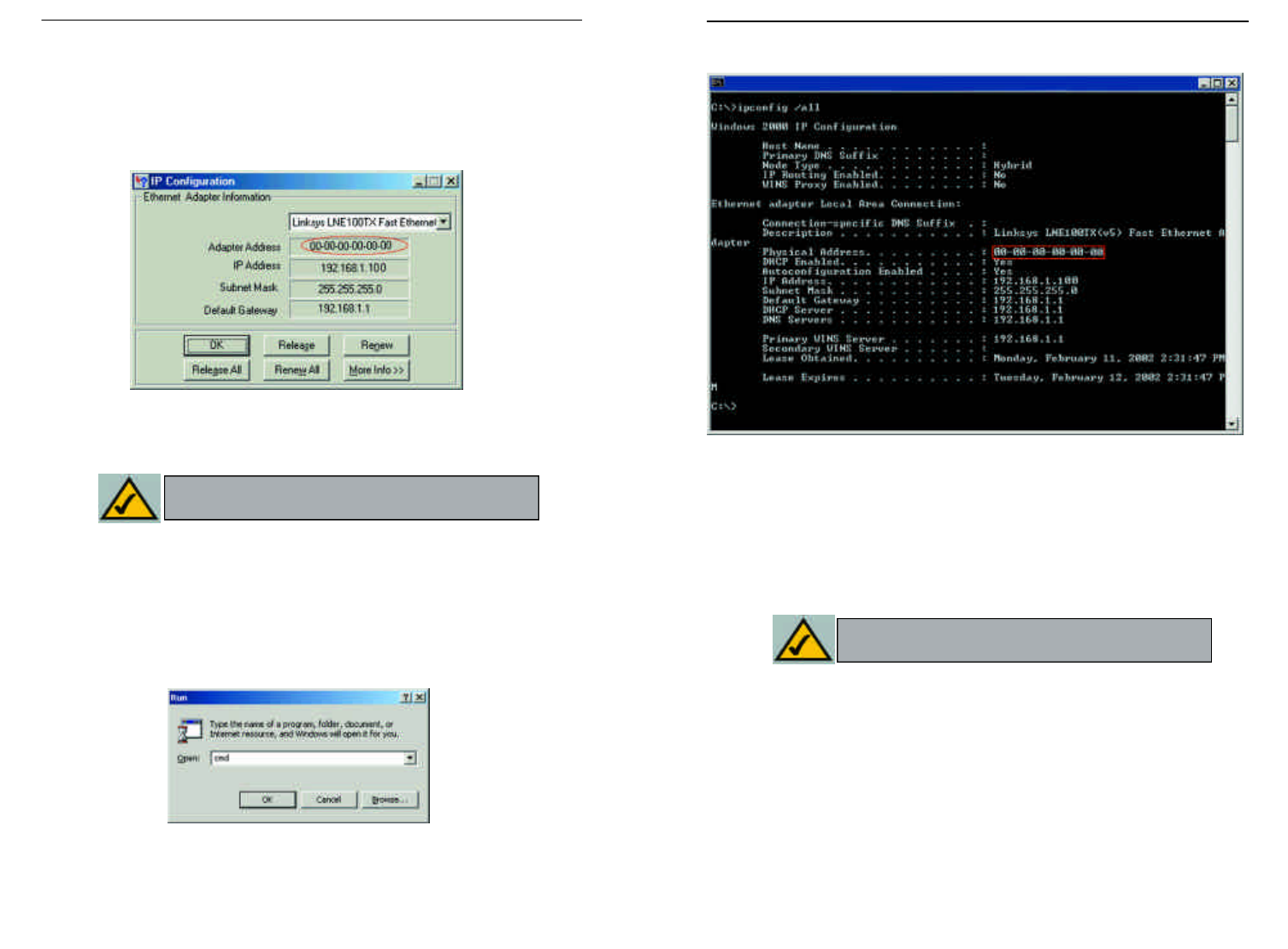
2. In the command prompt, enter ipconfig /all. Then press the Enter key.
3. Write down the Physical Address as shown on your computer screen; it is
the MAC address for your Ethernet adapter. This will appear as a series of
letters and numbers.
The MAC address/Physical Address is what you will use for MAC Address
Cloning or MAC Filtering.
The example in Figure D-5 shows the IP address of your Ethernet adapter
as 192.168.1.100. Your computer may show something different.
Figure D-5
Note:The MAC address is also called the Physical
Address.
3. Write down the Adapter Address as shown on your computer screen (see
Figure D-3). This is the MAC address for your Ethernet adapter and will
be shown as a series of numbers and letters.
The MAC address/Adapter Address is what you will use for MAC Address
Cloning or MAC Filtering.
The example in Figure F-3 shows the IP address of your Ethernet adapter
as 192.168.1.100. Your computer may show something different.
For Windows NT, 2000, and XP:
The following steps show an alternative way of obtaining the MAC address and
IP address for your Ethernet adapter.
1. Click on Start and Run. In the Open field, enter cmd, as shown in Figure
D-4. Press the Enter key or click the OK button.
Figure D-3
Figure D-4
Note:The MAC address is also called the Adapter
Address.
Instant WirelessTM Series Wireless Access Point Router with 4-Port Switch
85 86
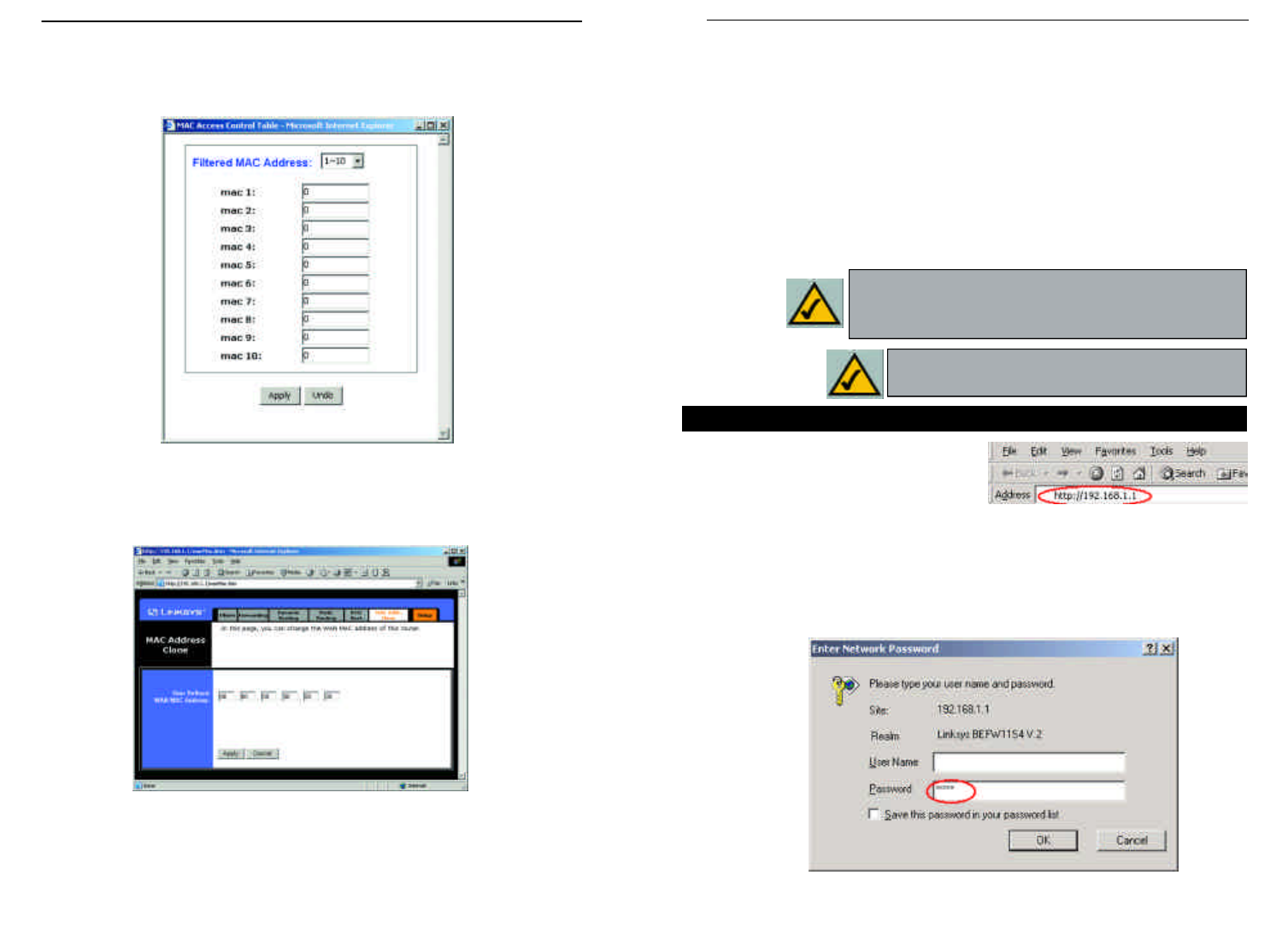
When entering the information using the Router’s web-based utility, you will
type the 12-digit MAC address in this format, XXXXXXXXXXXX without
the hyphensfor MAC Filtering. See Figure D-6.
When entering information for MAC Address Cloning, type the 12-digit MAC
address (see Figure D-7).
Figure D-6
Figure D-7
Instant WirelessTM Series
87
Appendix E: Setting Up AOL®
Broadband Cable & DSL
This document provides instructions for setting up the Router using firmware
version 1.43 or above to work with AOL Broadband via a Cable or DSL con-
nection. This Router's AOL Parental Controls feature is available for AOL cus-
tomers in the US only. Please follow the instructions in the appropriate section
below to configure for AOL Broadband for the type of broadband connection
you have.
1. Open your web browser. Enter
http://192.168.1.1 in the web
browser’s Address field, as shown in
Figure E-1, and press the Enter key.
2. A password request page, shown in Figure E-2 will appear. (Windows XP
users will see a Connect to 192.168.1.1 window slightly different from that
shown). Leave the User Name field blank, and enter admin in the Password
field. Then click the OK button. Ro
AOL Broadband via Cable
Figure E-1
Figure E-2
Note: Some of the screens in this section may look
slightly different than what appears on your screen.
Note: You must install AOL 7.0 or above to all computers
using AOL Services. Those with earlier versions of AOL
can find details at AOL Keyword: Linksys Setup.
88
Wireless Access Point Router with 4-Port Switch
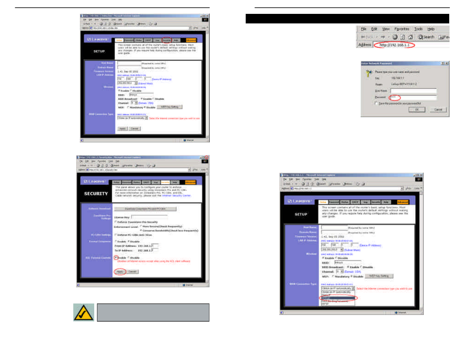
3. From the Setup
screen that appears,
shown in Figure E-3,
select Obtain an IP
automatically from
the WAN Connection
Type drop-down
menu. Then, click the
Security tab.
4. Select Enable for
AOL Parental
Controls from the
Security tab, shown
in Figure E-4, and
click the OK button
on the screen that
appears. Enabling
this will disable all
options under the
Advanced tab
except MAC
Address cloning.
Then, click the OK
button to save these
settings. Click the X
button on the top
right side of the win-
dow to close it.
Figure E-3
Figure E-4
Note: AOL Parental Controls are available
to AOL customers in the Unites States Only.
1. Open your web browser. Enter
http://192.168.1.1 in the web
browser’s Address field, as shown in
Figure E-5, and press the Enter key.
2. A password request page, shown in
Figure E-6 will appear. (Windows XP
users will see a Connect to
192.168.1.1 window slightly different
from that shown). Leave the User
Name field blank, and enter admin in
the Password field. Then click the
OK button.
3. From the Setup screen that appears, shown in Figure E-7, select PPPoE
from the WAN Connection Type drop-down menu. Enter america online
for the User Name. In the password field, multiple asterisks will appear.
Keep these settings and click the Apply button to save them. Click the X
button on the top right side of the window to close it.
AOL Broadband via DSL
Figure E-5
Figure E-6
Figure E-7
89 90
Instant WirelessTM Series Wireless Access Point Router with 4-Port Switch

Bit - A binary digit. The value - 0 or 1-used in the binary numbering system.
Also, the smallest form of data.
Boot - To cause the computer to start executing instructions. Personal comput-
ers contain built-in instructions in a ROM chip that are automatically executed
on startup. These instructions search for the operating system, load it and pass
control to it.
Broadband - A data-transmission scheme in which multiple signals share the
bandwidth of a medium. This allows the transmission of voice, data and video
signals over a single medium. Cable television uses broadband techniques to
deliver dozens of channels over one cable.
Browser - A browser is an application program that provides a way to look at
and interact with all the information on the World Wide Web or PC. The word
"browser" seems to have originated prior to the Web as a generic term for user
interfaces that let you browse text files online.
BSS (Basic Service Set) - An infrastructure network connecting wireless
devices to a wired network using a single access point.
Buffer - A buffer is a shared or assigned memory area used by hardware
devices or program processes that operate at different speeds or with different
sets of priorities. The buffer allows each device or process to operate without
being held up by the other. In order for a buffer to be effective, the size of the
buffer and the algorithms for moving data into and out of the buffer need to be
considered by the buffer designer. Like a cache, a buffer is a "midpoint holding
place" but exists not so much to accelerate the speed of an activity as to sup-
port the coordination of separate activities.
Cable Modem - A device that connects a computer to the cable television net-
work, which in turn connects to the Internet. Once connected, cable modem
users have a continuous connection to the Internet. Cable modems feature
asymmetric transfer rates: around 36 Mbps downstream (from the Internet to
the computer), and from 200 Kbps to 2 Mbps upstream (from the computer to
the Internet).
CAT 5- ANSI/EIA (American National Standards Institute/Electronic
Industries Association) Standard 568 is one of several standards that specify
"categories" (the singular is commonly referred to as "CAT") of twisted pair
91
Wireless Access Point Router with 4-Port Switch
Appendix F: Glossary
10BaseT - An Ethernet standard that uses twisted wire pairs.
100BaseTX - IEEE physical layer specification for 100 Mbps over two pairs of
Category 5 wire.
Adapter - Printed circuit board that plugs into a PC to add to capabilities or
connectivity to a PC. In a networked environment, a network interface card is
the typical adapter that allows the PC or server to connect to the intranet and/or
Internet.
Ad-hoc Network - An ad-hoc network is a group of computers, each with a
wireless adapter, connected as an independent 802.11 wireless LAN. Ad-hoc
wireless computers operate on a peer-to-peer basis, communicating directly
with each other without the use of an access point. Ad-hoc mode is also
referred to as an Independent Basic Service Set (IBSS) or as peer-to-peer
mode.
AppleTalk - An Apple Computer networking system that support Apple's pro-
prietary local talk.
Auto-negotiate - To automatically determine the correct settings. The term is
often used with communications and networking. For example, Ethernet
10/100 cards, hubs and switches can determine the highest speed of the node
they are connected to and adjust their transmission rate accordingly.
Backbone - The part of a network that connects most of the systems and net-
works together and handles the most data.
Bandwidth - The transmission capacity of a given facility, in terms of how
much data the facility can transmit in a fixed amount of time; expressed in bits
per second (bps).
Beacon Interval - A beacon is a packet broadcast by the Access Point to keep
the network synchronized. A beacon includes the wireless LAN service area,
the AP address, the Broadcast destination addresses, a time stamp, Delivery
Traffic Indicator Maps, and the Traffic Indicator Message (TIM).
92
Instant WirelessTM Series

cially useful in education and other environments where users change fre-
quently. Using very short leases, DHCP can dynamically reconfigure networks
in which there are more computers than there are available IP addresses.
DHCP supports static addresses for computers containing Web servers that
need a permanent IP address.
DMZ (Demilitarized Zone) - Allows one IP address (or computer) to be
exposed to the Internet. Some applications require multiple TCP/IP ports to be
open. It is recommended that you set your computer with a static IP address if
you want to use DMZ Hosting.
DNS - The domain name system (DNS) is the way that Internet domain name
are located and translated into Internet Protocol (IP) addresses. A domain name
is a meaningful and easy-to-remember "handle" for an Internet address.
Domain - A subnetwork comprised of a group of clients and servers under the
control of one security database. Dividing LANs into domains improves per-
formance and security.
Download - To receive a file transmitted over a network. In a communications
session, download means receive, upload means transmit.
DSL (Digital Subscriber Line) - A technology that dramatically increases the
digital capacity of ordinary telephone lines into the home or office and, by
employing unused bandwidth, still allows for normal phone usage. DSL pro-
vides "always-on" operation, eliminating the need to dial in to the service.
DSSS (Direct-Sequence Spread Spectrum) - DSSS generates a redundant bit
pattern for all data transmitted. This bit pattern is called a chip (or chipping
code). Even if one or more bits in the chip are damaged during transmission,
statistical techniques embedded in the receiver can recover the original data
without the need for retransmission. To an unintended receiver, DSSS appears
as low power wideband noise and is rejected (ignored) by most narrowband
receivers. However, to an intended receiver (i.e. another wireless LAN end-
point), the DSSS signal is recognized as the only valid signal, and interference
is inherently rejected (ignored).
DTIM (Delivery Traffic Indication Message) - A DTIM field is a countdown
field informing clients of the next window for listening to broadcast and mul-
ticast messages. When the AP has buffered broadcast or multicast messages for
93
Wireless Access Point Router with 4-Port Switch
cabling systems (wires, junctions, and connectors) in terms of the data rates
that they can sustain. CAT 5 cable has a maximum throughput of 100 Mbps and
is usually utilized for 100BaseTX networks.
CAT 5e - The additional cabling performance parameters of return loss and far-
end crosstalk (FEXT) specified for 1000BASE-T and not specified for
10BASE-T and 100BASE-TX are related to differences in the signaling imple-
mentation. 10BASE-T and 100BASE-TX signaling is unidirectional-signals
are transmitted in one direction on a single wire pair. In contrast, Gigabit
Ethernet is bi-directional-signals are transmitted simultaneously in both direc-
tions on the same wire pair; that is, both the transmit and receive pair occupy
the same wire pair.
CSMA/CA (Carrier Sense Multiple Access/Collision Avoidance) - In local
area networking, this is the CSMA technique that combines slotted time-divi-
sion multiplexing with carrier sense multiple access/collision detection
(CSMA/CD) to avoid having collisions occur a second time. This works best if
the time allocated is short compared to packet length and if the number of sit-
uations is small.
Data Packet - One frame in a packet-switched message. Most data communi-
cations is based on dividing the transmitted message into packets. For example,
an Ethernet packet can be from 64 to 1518 bytes in length.
Default Gateway - The routing device used to forward all traffic that is not
addressed to a station within the local subnet.
DHCP (Dynamic Host Configuration Protocol) - A protocol that lets network
administrators manage centrally and automate the assignment of Internet
Protocol (IP) addresses in an organization's network. Using the Internet's set of
protocol (TCP/IP), each machine that can connect to the Internet needs a
unique IP address. When an organization sets up its computer users with a con-
nection to the Internet, an IP address must be assigned to each machine.
Without DHCP, the IP address must be entered manually at each computer and,
if computers move to another location in another part of the network, a new IP
address must be entered. DHCP lets a network administrator supervise and dis -
tribute IP addresses from a central point and automatically sends a new IP
address when a computer is plugged into a different place in the network.
DHCP uses the concept of a "lease" or amount of time that a given IP address
will be valid for a computer. The lease time can vary depending on how long a
user is likely to require the Internet connection at a particular location. It's espe-
94
Instant WirelessTM Series

Firewall - A firewall is a set of related programs, located at a network gateway
server, that protects the resources of a network from users from other networks.
(The term also implies the security policy that is used with the programs.) An
enterprise with an intranet that allows its workers access to the wider Internet
installs a firewall to prevent outsiders from accessing its own private data
resources and for controlling what outside resources to which its own users
have access.
Basically, a firewall, working closely with a router, examines each network
packet to determine whether to forward it toward its destination.
Firmware - Code that is written onto read-only memory (ROM) or program-
mable read-only memory (PROM). Once firmware has been written onto the
ROM or PROM, it is retained even when the device is turned off.
Fragmentation - Breaking a packet into smaller units when transmitting over
a network medium that cannot support the original size of the packet.
FTP (File Transfer Protocol) - A protocol used to transfer files over a TCP/IP
network (Internet, UNIX, etc.). For example, after developing the HTML pages
for a Web site on a local machine, they are typically uploaded to the Web serv-
er using FTP.
FTP includes functions to log onto the network, list directories and copy files.
It can also convert between the ASCII and EBCDIC character codes. FTP oper-
ations can be performed by typing commands at a command prompt or via an
FTP utility running under a graphical interface such as Windows. FTP transfers
can also be initiated from within a Web browser by entering the URL preceded
with ftp://.
Unlike e-mail programs in which graphics and program files have to be
"attached," FTP is designed to handle binary files directly and does not add the
overhead of encoding and decoding the data.
Full Duplex - The ability of a device or line to transmit data simultaneously in
both directions.
Gateway - A device that interconnects networks with different, incompatible
communications protocols.
Half Duplex - Data transmission that can occur in two directions over a single
line, but only one direction at a time.
95
Wireless Access Point Router with 4-Port Switch
associated clients, it sends the next DTIM with a DTIM Interval value. AP
Clients hear the beacons and awaken to receive the broadcast and multicast
messages.
Dynamic IP Address- An IP address that is automatically assigned to a client
station in a TCP/IP network, typically by a DHCP server. Network devices that
serve multiple users, such as servers and printers, are usually assigned static IP
addresses.
Dynamic Routing- The ability for a router to forward data via a different route
based on the current conditions of the communications circuits. For example,
it can adjust for overloaded traffic or failing lines and is much more flexible
than static routing, which uses a fixed forwarding path.
Encryption - A security method that applies a specific algorithm to data in
order to alter the data's appearance and prevent other devices from reading the
information.
ESS (Extended Service Set) - A set of more than two or more BSSs (multiple
access points) forming a single network.
Ethernet - IEEE standard network protocol that specifies how data is placed
on and retrieved from a common transmission medium. Has a transfer rate of
10 Mbps. Forms the underlying transport vehicle used by several upper-level
protocols, including TCP/IP and XNS.
Fast Ethernet - A 100 Mbps technology based on the 10Base-T Ethernet
CSMA/CD network access method.
FHSS (Frequency Hopping Spread Spectrum) - FHSS continuously changes
(hops) the carrier frequency of a conventional carrier several times per second
according to a pseudo-random set of channels. Because a fixed frequency is not
used, and only the transmitter and receiver know the hop patterns, interception
of FHSS is extremely difficult.
Finger - A UNIX command widely used on the Internet to find out informa-
tion about a particular user, such as telephone number, whether currently
logged on or the last time logged on. The person being "fingered" must have
placed his or her profile on the system. Fingering requires entering the full
user@domain address.
96
Instant WirelessTM Series

IP Address - In the most widely installed level of the Internet Protocol
(Internet Protocol) today, an IP address is a 32-binary digit number that identi-
fies each sender or receiver of information that is sent in packet across the
Internet. When you request an HTML page or send e-mail, the Internet
Protocol part of TCP/IP includes your IP address in the message (actually, in
each of the packets if more than one is required) and sends it to the IP address
that is obtained by looking up the domain name in the Uniform Resource
Locator you requested or in the e-mail address you're sending a note to. At the
other end, the recipient can see the IP address of the Web page requestor or the
e-mail sender and can respond by sending another message using the IP address
it received.
IPCONFIG - A Windows NT or 2000 utility that provides for querying, defin-
ing and managing IP addresses within a network. A commonly used utility for
configuring networks with static IP addresses.
IPSec (Internet Protocol Security) - A suite of protocols used to implement
secure exchange of packets at the IP layer. IPSec supports two basic modes:
Transport and Tunnel. Transport encrypts the payload of each packet, leaving
the header untouched, while Tunnel mode encrypts both the header and the pay-
load and is therefore more secure. IPSec must be supported on both transmit-
ter and receiver and must share a public key. Tunnel mode is widely deployed
in VPNs (Virtual Private Networks).
IPX (Internetwork Packet EXchange) - A NetWare communications protocol
used to route messages from one node to another. IPX packets include network
addresses and can be routed from one network to another.
ISM band - The FCC and their counterparts outside of the U.S. have set aside
bandwidth for unlicensed use in the ISM (Industrial, Scientific and Medical)
band. Spectrum in the vicinity of 2.4 GHz, in particular, is being made avail-
able worldwide. This presents a truly revolutionary opportunity to place con-
venient high-speed wireless capabilities in the hands of users around the globe.
ISP - An ISP (Internet service provider) is a company that provides individuals
and companies access to the Internet and other related services such as Web site
building and virtual hosting.
LAN - A local area network (LAN) is a group of computers and associated
devices that share a common communications line and typically share the
resources of a single processor or server within a small geographic area (for
example, within an office building).
Wireless Access Point Router with 4-Port Switch
97
Hardware - Hardware is the physical aspect of computers, telecommunica-
tions, and other information technology devices. The term arose as a way to dis -
tinguish the "box" and the electronic circuitry and components of a computer
from the program you put in it to make it do things. The program came to be
known as the software.
Hop - The link between two network nodes.
HTTP (HyperText Transport Protocol) - The communications protocol used
to connect to servers on the World Wide Web. Its primary function is to estab-
lish a connection with a Web server and transmit HTML pages to the client
browser.
Hub - The device that serves as the central location for attaching wires from
workstations. Can be passive, where there is no amplification of the signals; or
active, where the hubs are used like repeaters to provide an extension of the
cable that connects to a workstation.
ICQ - A conferencing program for the Internet that provides interactive chat,
e-mail and file transfer and can alert you when someone on your predefined list
has also come online.
IEEE (The Institute of Electrical and Electronics Engineers) - The IEEE
describes itself as "the world's largest technical professional society, promoting
the development and application of electrotechnology and allied sciences for
the benefit of humanity, the advancement of the profession, and the well-being
of our members."
The IEEE fosters the development of standards that often become national and
international standards. The organization publishes a number of journals, has
many local chapters, and several large societies in special areas, such as the
IEEE Computer Society.
Infrastructure Network - An infrastructure network is a group of computers
or other devices, each with a wireless adapter, connected as an 802.11 wireless
LAN. In infrastructure mode, the wireless devices communicate with each
other and to a wired network by first going through an access point. An infra-
structure wireless network connected to a wired network is referred to as a
Basic Service Set (BSS). A set of two or more BSS in a single network is
referred to as an Extended Service Set (ESS). Infrastructure mode is useful at
a corporation scale, or when it is necessary to connect the wired and wireless
networks.
Instant WirelessTM Series
98

Plug-and-Play - The ability of a computer system to configure expansion
boards and other devices automatically without requiring the user to turn off
the system during installation.
Port - A pathway into and out of the computer or a network device such as a
switch or router. For example, the serial and parallel ports on a personal com-
puter are external sockets for plugging in communications lines, modems and
printers.
PPPoE (Point to Point Protocol over Ethernet) - PPPoE is a method for the
encapsulation of PPP packets over Ethernet frames from the user to the ISP
over the Internet. One reason PPPoE is preferred by ISPs is because it provides
authentication (username and password) in addition to data transport. A PPPoE
session can be initiated by either a client application residing on a PC, or by
client firmware residing on a modem or router.
PPTP (Point-to-Point Tunneling Protocol) - A protocol (set of communication
rules) that allows corporations to extend their own corporate network through
private "tunnels" over the public Internet. Effectively, a corporation uses a
wide-area network as a single large local area network. A company no longer
needs to lease its own lines for wide-area communication but can securely use
the public networks. This kind of interconnection is known as a virtual private
network.
RIP(Routing Information Protocol) - A simple routing protocol that is part of
the TCP/IP protocol suite. It determines a route based on the smallest hop count
between source and destination. RIP is a distance vector protocol that routine-
ly broadcasts routing information to its neighboring routers.
RJ-45 (Registered Jack-45) - A connector similar to a telephone connector that
holds up to eight wires, used for connecting Ethernet devices.
Roaming - In an infrastructure mode wireless network, this refers to the abili-
ty to move out of one access point's range and into another and transparently
reassociate and reauthenticate to the new access point. This reassociation and
reauthentication should occur without user intervention and ideally without
interruption to network connectivity. A typical scenario would be a location
with multiple access points, where users can physically relocate from one area
to another and easily maintain connectivity.
Wireless Access Point Router with 4-Port Switch
99
MAC (Media Access Control) Address - A unique number assigned by the
manufacturer to any Ethernet networking device, such as a network adapter,
that allows the network to identify it at the hardware level.
Mbps (MegaBits Per Second) - One million bits per second; unit of measure-
ment for data transmission.
MIB (Management Information Base) - A set of database objects. This set con-
tains information about a specific device for utilizing SNMP.
mIRC - mIRC runs under Windows and provides a graphical interface for log-
ging onto IRC servers and listing, joining and leaving channels.
Multicasting - Sending data to a group of nodes instead of a single destination.
NAT (Network Address Translation) - The translation of an Internet Protocol
address (IP address) used within one network to a different IP address known
within another network. One network is designated the inside network and the
other is the outside.
Network - A system that transmits any combination of voice, video and/or data
between users.
NNTP (Network News Transfer Protocol) - The protocol used to connect to
Usenet groups on the Internet. Usenet newsreaders support the NNTP protocol.
Node - A network junction or connection point, typically a computer or work
station.
Packet- A unit of data routed between an origin and a destination in a network.
Passphrase - Used much like a password, a passphrase simplifies the WEP
encryption process by automatically generating the WEP encryption keys for
Linksys products.
PC Card - A credit-card sized removable module that contains memory, I/O,
or a hard disk.
Ping (Packet INternet Groper) - An Internet utility used to determine whether
a particular IP address is online. It is used to test and debug a network by send-
ing out a packet and waiting for a response.
Instant WirelessTM Series
100

If a receiver is not tuned to the right frequency, a spread-spectrum signal looks
like background noise. There are two main alternatives, Direct Sequence
Spread Spectrum (DSSS) and Frequency Hopping Spread Spectrum (FHSS).
SPI (Stateful Packet Inspection) - A firewall technology that monitors the state
of the transaction so that it can verify that the destination of an inbound pack-
et matches the source of a previous outbound request. It examines not just the
headers of the packet, but also the contents, to determine more about the pack-
et than just its source and destination information. It is called "stateful" because
verifies that the stated destination computer has previously requested the cur-
rent communication. In this way, it verifies that all communications are initiat-
ed by the recipient computer and are taking place only with sources that are
known and trusted from previous interactions. In addition to being a more rig-
orous inspection, stateful packet inspection closes off ports until connection to
the specific port is requested. This allows an added layer of protection from the
threat of port scanning.
SSID (Service Set IDentifier) - A unique name shared among all points in a
wireless network. The SSID must be identical for each point in the wireless net-
work and is case-sensitive.
Static IP Address - A permanent IP address that is assigned to a node in an IP
or a TCP/IP network.
Static Routing - Forwarding data in a network via a fixed path. Static routing
cannot adjust to changing line conditions as can dynamic routing.
Subnet Mask - The method used for splitting IP networks into a series of sub-
groups, or subnets. The mask is a binary pattern that is matched up with the IP
address to turn part of the host ID address field into a field for subnets.
Switch - 1. A data switch connects computing devices to host computers,
allowing a large number of devices to share a limited number of ports. 2. A
device for making, breaking, or changing the connections in an electrical cir-
cuit.
TCP (Transmission Control Protocol) - A method (protocol) used along with
the IP (Internet Protocol) to send data in the form of message units (datagram)
between network devices over a LAN or WAN. While IP takes care of handling
the actual delivery of the data (routing), TCP takes care of keeping track of the
individual units of data (called packets) that a message is divided into for effi-
Wireless Access Point Router with 4-Port Switch
101
Router - Protocol-dependent device that connects subnetworks together.
Routers are useful in breaking down a very large network into smaller subnet-
works; they introduce longer delays and typically have much lower throughput
rates than bridges.
RTS (Request To Send) - An RS-232 signal sent from the transmitting station
to the receiving station requesting permission to transmit.
Server - Any computer whose function in a network is to provide user access
to files, printing, communications, and other services.
SMTP (Simple Mail Transfer Protocol) - The standard e-mail protocol on the
Internet. It is a TCP/IP protocol that defines the message format and the mes -
sage transfer agent (MTA), which stores and forwards the mail.
SNMP (Simple Network Management Protocol) - A widely used network
monitoring and control protocol. Data is passed from SNMP agents, which are
hardware and/or software processes reporting activity in each network device
(hub, router, bridge, etc.) to the workstation console used to oversee the net-
work. The agents return information contained in a MIB (Management
Information Base), which is a data structure that defines what is obtainable
from the device and what can be controlled (turned off, on, etc.).
Software - Instructions for the computer. A series of instructions that performs
a particular task is called a "program." The two major categories of software are
"system software" and "application software." System software is made up of
control programs such as the operating system and database management sys-
tem (DBMS). Application software is any program that processes data for the
user.
A common misconception is that software is data. It is not. Software tells the
hardware how to process the data.
Spread Spectrum - Spread Spectrum technology is a wideband radio frequen-
cy technique developed by the military for use in reliable, secure, mission-crit-
ical communications systems. It is designed to trade off bandwidth efficiency
for reliability, integrity, and security. In other words, more bandwidth is con-
sumed than in the case of narrowband transmission, but the trade off produces
a signal that is, in effect, louder and thus easier to detect, provided that the
receiver knows the parameters of the spread-spectrum signal being broadcast.
Instant WirelessTM Series
102

UTP - Unshielded twisted pair is the most common kind of copper telephone
wiring. Twisted pair is the ordinary copper wire that connects home and many
business computers to the telephone company. To reduce crosstalk or electro-
magnetic induction between pairs of wires, two insulated copper wires are
twisted around each other. Each signal on twisted pair requires both wires.
Since some telephone sets or desktop locations require multiple connections,
twisted pair is sometimes installed in two or more pairs, all within a single
cable.
VPN(Virtual Private Network) - A technique that allows two or more LANs to
be extended over public communication channels by creating private commu-
nication subchannels (tunnels). Effectively, these LANs can use a WAN as a
single large "virtually private" LAN. This removes the need to use leased lines
for WAN communications through secure use of a publicly available WAN
(such as the Internet). Examples of VPN technology are: PPTP (Point to Point
Tunneling Protocol), L2TP (Layer 2 Tunneling Protocol), and IPSec (Internet
Protocol Security).
WAN (Wide Area Network)- A communications network that covers a rela-
tively large geographic area, consisting of two or more LANs. Broadband
communication over the WAN is often through public networks such as the
telephone (DSL) or cable systems, or through leased lines or satellites. In its
most basic definition, the Internet could be considered a WAN.
WEP (Wired Equivalent Privacy) - A data privacy mechanism based on a 64-
bit or 128-bit shared key algorithm, as described in the IEEE 802.11 standard.
WINIPCFG - Configuration utility based on the Win32 API for querying,
defining and managing IP addresses within a network. A commonly used util-
ity for configuring networks with static IP addresses.
Wireless Access Point Router with 4-Port Switch
103
cient delivery over the network. TCP is known as a "connection oriented" pro-
tocol due to requiring the receiver of a packet to return an acknowledgment of
receipt to the sender of the packet resulting in transmission control.
TCP/IP (Transmission Control Protocol/Internet Protocol) - The basic com-
munication language or set of protocols for communications over a network
(developed specifically for the Internet). TCP/IP defines a suite or group of
protocols and not only TCP and IP.
Telnet - A terminal emulation protocol commonly used on the Internet and
TCP/IP-based networks. It allows a user at a terminal or computer to log onto
a remote device and run a program.
TFTP (Trivial File Transfer Protocol) - A version of the TCP/IP FTP protocol
that has no directory or password capability.
Throughput - The amount of data moved successfully from one place to
another in a given time period.
TX Rate - Transmission Rate.
UDP (User Datagram Protocol) - A method (protocol) used along with the IP
(Internet Protocol) to send data in the form of message units (datagram)
between network devices over a LAN or WAN. While IP takes care of handling
the actual delivery of the data (routing), UDP takes care of keeping track of the
individual units of data (called packets) that a message is divided into for effi-
cient delivery over the network. UDP is known as a "connection-less" protocol
due to NOT requiring the receiver of a packet to return an acknowledgment of
receipt to the sender of the packet (as opposed to TCP).
Upgrade- To replace existing software or firmware with a newer version.
Upload - To transmit a file over a network. In a communications session,
upload means transmit, download means receive.
URL (Uniform Resource Locator) - The address that defines the route to a file
on the Web or any other Internet facility. URLs are typed into the browser to
access Web pages, and URLs are embedded within the pages themselves to pro-
vide the hypertext links to other pages.
Instant WirelessTM Series
104

105
Dimensions 186mm x 154mm x 62mm (7.31" x 6.06" x 2.44")
Unit Weight 0.56 kg. (19.2 oz.)
Power Input External, 5V DC, 2.5A
Certifications FCC Class B, CE Mark
Operating Temperature 0ºC to 40ºC (32ºF to 104ºF)
Storage Temperature -20ºC to 70ºC (-4ºF to 158ºF)
Operating Humidity 10% to 85%, Non-Condensing
Storage Humidity 5% to 90%, Non-Condensing
Environmental
Wireless Access Point Router with 4-Port Switch
Appendix G: Specifications
Standards IEEE 802.3 (10BaseT), IEEE 802.3u
(100BaseTX), IEEE 802.11b (Wireless)
Protocol CSMA/CD
Ports
WAN: One 10Base-T RJ-45 Port for cable or DSL
Modem
LAN: Four 10/100 RJ-45 Switched Ports,
One Shared Uplink Port
Speed (Mbps) WAN: 10 (Half Duplex)
LAN: 10/100 (Half Duplex)
20/200 (Full Duplex)
Cabling Type UTP Category 5 or better
Button Reset
TX Power 19 dbm
Throughput (average) 4.2 Mbps
Receiver Sensitivity (Typical) 1Mbps 0-5 BER @ -89dbm
5.5Mbps 10-5 BER @ -83dbm
11Mbps 10-5 BER @ -79dbm
Topology Star (Ethernet)
LED Indicators Power, WLAN Activity, WLAN Link
WAN Link/Activity, Diag for WAN
LAN Full Duplex/Collision, Link/Activity 100
Connectors 2 Antenna Connectors
106
Instant WirelessTM Series

Appendix I: Warranty Information
LIMITED WARRANTY
Linksys guarantees that every Instant Wireless™ Wireless Access Point Router with 4-Port
Switch is free from physical defects in material and workmanship for two years from the
date of purchase (Africa, Europe and Latin America only, other regions may have a dif-
ferent warranty period), when used within the limits set forth in the Specifications section
of this User Guide. If you suspect the product is defective during the warranty period,
contact the Linksys Technical Support in order to obtain a Return Authorization number
(RMA) or contact the location where the product was purchased (if applicable). BE SURE
TO HAVE YOUR PROOF OF PURCHASE ON HAND WHEN CONTACTING TECHNICAL
SUPPORT. RETURN REQUESTS CANNOT BE PROCESSED WITHOUT PROOF OF PUR-
CHASE.
IN NO EVENT SHALL LINKSYS’ LIABILITY EXCEED THE PRICE PAID FOR THE PROD-
UCT FROM DIRECT, INDIRECT, SPECIAL, INCIDENTAL, OR CONSEQUENTIAL DAM-
AGES RESULTING FROM THE USE OF THE PRODUCT, ITS ACCOMPANYING SOFT-
WARE, OR ITS DOCUMENTATION. LINKSYS OFFERS NO REFUNDS FOR ITS PROD-
UCTS. Linksys makes no warranty or representation, expressed, implied, or statutory,
with respect to its products or the contents or use of this documentation and all accom-
panying software, and specifically disclaims its quality, performance, merchantability, or
fitness for any particular purpose. Linksys reserves the right to revise or update its prod-
ucts, software, or documentation without obligation to notify any individual or entity.
Please direct all inquiries to the address listed below or contact Technical support:
Linksys
P.O. Box 18558
Irvine, California 92623
U.S.A.
107
Wireless Access Point Router with 4-Port Switch
108
Appendix H: Contact Information
For help with installation or operation of this product, contact Linksys
Technical Support at one of the phone numbers listed in the Technical
Support insert or Internet addresses below:
E-mail
Europe europe-support@linksys.com
United Kingdom & Ireland uks@linksys.com
Latin America latam-soporte@linksys.com
U.S. and Canada support@linksys.com
For unlisted regions or updated contact information please visit the website
below:
Web http://www.linksys.com/international
Instant WirelessTM Series

© Copyright 2002 Linksys, All Rights Reserved.
Printed in the USA.
http://www.linksys.com