Clou IOT Technologies CLOUIOTCL7206C RFID Reader User Manual
Shenzhen Clou IOT Technologies Co.,Ltd. RFID Reader
User Manual

User Manual of
CL7206C RFID Reader
Shenzhen Clou IOT Technologies Co., Ltd
(V2.0.2)
Welcome to be user of CLOU RFID products. Thanks for choosing CLOU’s 4-port
Fixed RFID Reader CL7206C. We believe our device will bring convenience for your
work.
Catalogue
1. Technical Specification ............................................................................................................................................ 6
1.1 Feature ............................................................................................................................................................................ 6
1.2 Technical ......................................................................................................................................................................... 6
1.2.1 Main function ...................................................................................................................................................... 6
1.2.2 Technical parameter ......................................................................................................................................... 7
1.2.3 Operational environment ............................................................................................................................. 7
2. Sketch map .................................................................................................................................................................... 8
2.1 Physical construction ............................................................................................................................................... 8
2.2 Weight ............................................................................................................................................................................. 8
2.3 Illustration of LED display ..................................................................................................................................... 8
2.4 Interfaces ....................................................................................................................................................................... 9
2.4.1 Power supply, communication and I/O interface ............................................................................. 9
2.4.2 I/O Interface definition ................................................................................................................................ 10
2.4.3 Feeding line(optional) .................................................................................................................................. 12
2.4.4 Network connection diagram ................................................................................................................... 12
3. Installation ................................................................................................................................................................... 14
3.1 Notes ............................................................................................................................................................................. 14
3.2 Installation conditions .......................................................................................................................................... 14
3.3 Device connection .................................................................................................................................................. 14
3.3.1 Power on ............................................................................................................................................................. 14
3.3.2 Antenna connection ...................................................................................................................................... 15
3.3.3 PC connection ................................................................................................................................................... 15
3.4 Device installation ................................................................................................................................................... 15
3.5 Acceptance ................................................................................................................................................................. 15
3.5.1 Acceptance of structure ............................................................................................................................... 15
3.5.2 Performance acceptance ............................................................................................................................. 16
4. Software operating ................................................................................................................................................. 17
4.1 Demo software ......................................................................................................................................................... 17
4.2 Application environment ..................................................................................................................................... 17
4.3 Software version ...................................................................................................................................................... 17
4.4 Installation .................................................................................................................................................................. 17
4.5 Operation .................................................................................................................................................................... 18
4.5.1 Device connection .......................................................................................................................................... 18
4.5.2 Data display area ............................................................................................................................................. 22
4.5.3 Write data ........................................................................................................................................................... 26
4.5.4 TCP server / client mode ............................................................................................................................. 29
4.5.5 Antenna configuration ................................................................................................................................. 30
4.5.6 Base band parameter configuration ..................................................................................................... 31
4.5.7 Antenna port power setting ...................................................................................................................... 32
4.5.8 Clock setting ...................................................................................................................................................... 33
4.5.9 Frequency Hopping ....................................................................................................................................... 34
4.5.10 Label filtering ................................................................................................................................................. 35
4.5.11 Buffer and breakpoint resume ............................................................................................................... 36
4.5.12 Auto idle set up ............................................................................................................................................. 38
4.5.13 GPI/O configuration .................................................................................................................................... 39
4.5.14 Others ................................................................................................................................................................. 41
4.5.15 Tools .................................................................................................................................................................... 42
5. Common failures ...................................................................................................................................................... 45
5.1 Daily maintenance .................................................................................................................................................. 45
5.2 Common failure analysis and solution ......................................................................................................... 45
6. Package .......................................................................................................................................................................... 47
6.1 Package ........................................................................................................................................................................ 47
6.2 Accessories ................................................................................................................................................................. 47
6.3 Storage environment ............................................................................................................................................. 48
7. After-sale service ...................................................................................................................................................... 52
6
1. Technical Specification
1.1 Feature
CL7206C is a high performance eight antenna port fixed UHF RFID reader and writer;
support ISO18000-6C/6B protocols. The work frequency includes China standard dual
frequency 920MHz ~ 925MHz and 840MHz~845MHz, FCC 902MHz ~ 928MHz and ETSI
865MHz ~ 868MHz.
Output power from 0 ~ 33dBm optional, with long identification distance, fast reading
speed, high accurate rate, strong anti-interference ability, good protection performance and
easy installation
1.2 Technical
1.2.1 Main function
Protocol: support ISO18000-6C/6B standard
Built-in LINUX operating system
Multiple communication port (Ethernet, RS232, RS485, USB),
Support tag data filtering
Support RSSI: the intensity of the perceived signal
Adjustable RF output power
Optional working mode: constant frequency / frequency hopping
Supports antenna detection function
Supports online and remote upgrade
I/O interface: 4 port opt coupler input, 4 port relay output and Weigand output
7
1.2.2 Technical parameter
Working frequency: ETSI 865MHz~868MHz
Output power (port): 33dBm + 1dB (MAX)
Power adjustment: 1 dB step-by-step
Reading distance: 0 ~8meters (depending on tags, antennas and environment)
Channel bandwidth: <200 KHz
RS232 serial communication rate: 115200bps (default), 19200 bps, 9600bps
RS485 interface communication rate: 115200bps (default), 19200 bps, 9600bps
Wiegand output support wiegand 66, 34 & 26 types.
Power supply: 30V ~ 10V (power capacity is not less than 60W)
Power adapter: AC input 100V ~ 50Hz, 240V ~ 60Hz
DC output: 24V/2.5A
High protection grade: IP53
1.2.3 Operational environment
Working environment: -20℃~+30℃
Relative Humidity: 5%RH~90%RH(+25℃)
8
2. Sketch map
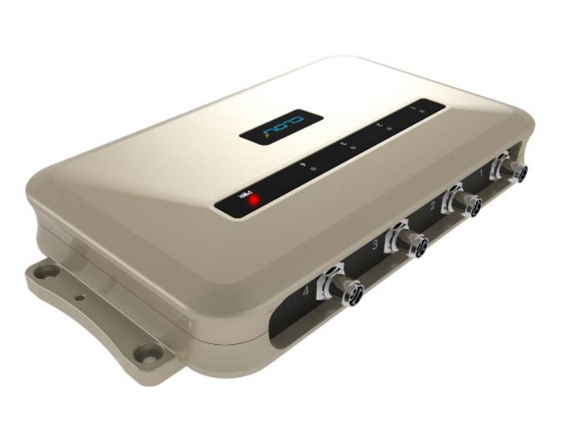
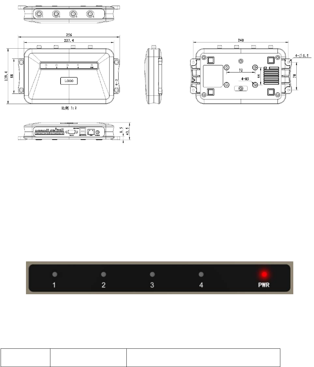
2.1 Physical construction
Image 2-1 Structure diagram of CL7206C
Size: 256mm*147.6mm*43.47mm
2.2 Weight
Main body: 1.14kg(accessories excluded)
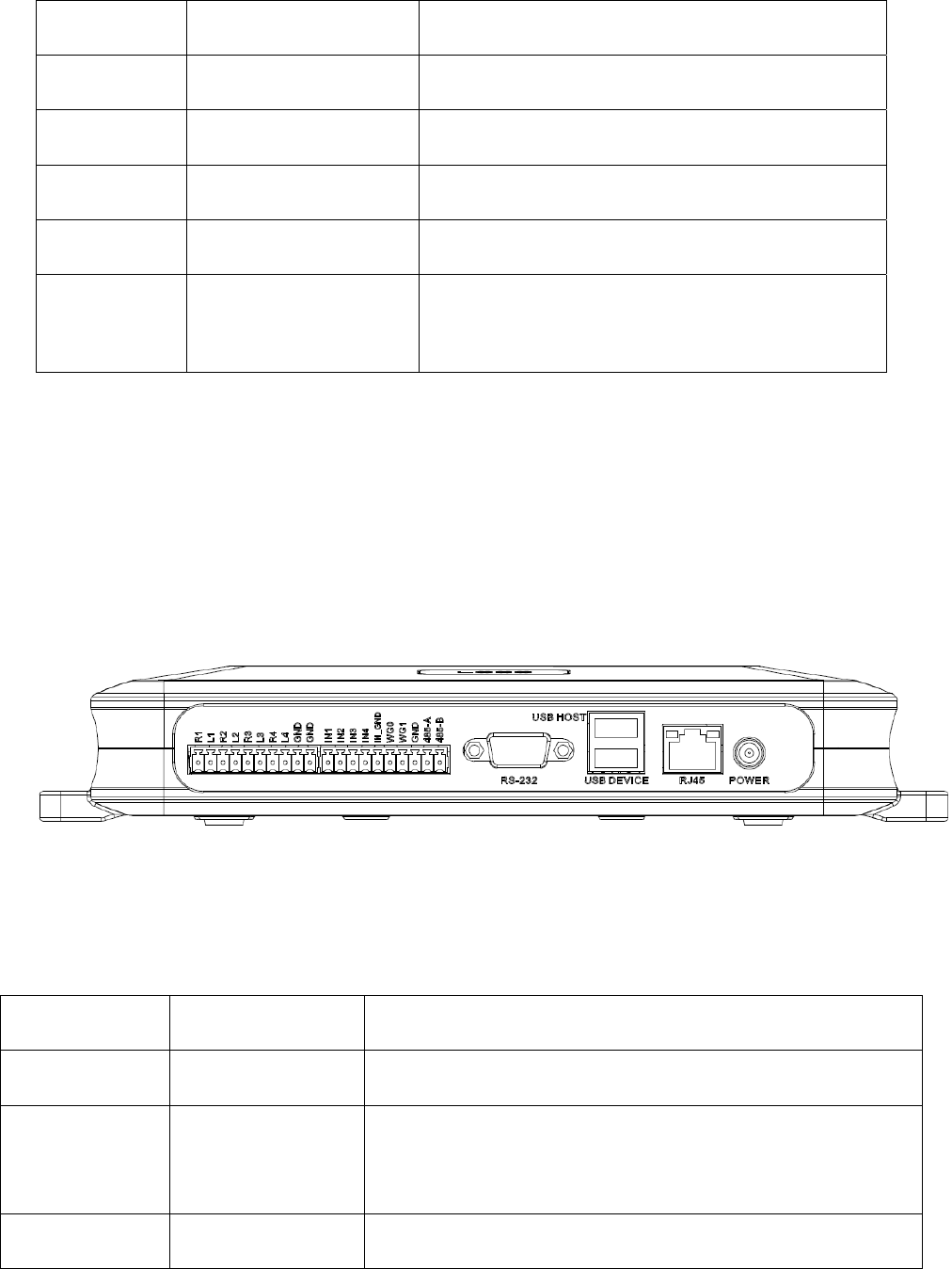
2.3 Illustration of LED display
Image2-2 Sketch map of reader’s LED indicator
LED indicator panel describe as below Form 2-1:
Form 2-1 LED indicator description
LED Mark Mark NO. Status description
9
NO.
ANT1 Antenna 1 indicator Indicates antenna 1 is working
ANT2 Antenna 2 indicator Indicates antenna 2 is working
ANT3 Antenna 3 indicator Indicates antenna 3 is working
ANT4 Antenna 4 indicator Indicates antenna 4 is working
POWER Power indicator
Keep bright indicates power supply working
normally
2.4 Interfaces
2.4.1 Power supply, communication and I/O interface
Image 2-3 Sketch map of reader’s power supply, communication and I/O interface,
Details are shown in form 2-2
Form 2-2 Reader’s power supply, communication and I/O interface,
Interface ID Interface Name Detail description
POWER Power supply DC,10~30V, power capacity no less than 60W.
RJ45 Ethernet interface
10/100M Ethernet interface, the reader control and
communication interface.
USB DEVICE USB device port PC and other PC connected, the reader control and
10
communication interface.
USB HOST USB host port
For external U disk, wireless LAN and other expansion
devices.
RS-232 RS-232 serial port Serial communication interface with control reader.
Other I/O interface See detailed definition 2.4.2.
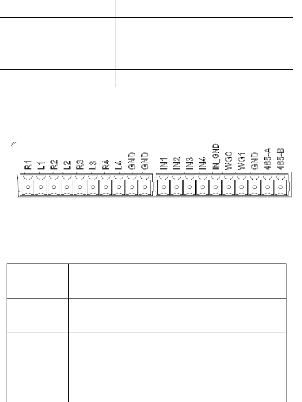
2.4.2 I/O Interface definition
Image 2-4 Sketch map of I/O control interface
I/O control signal define as follow form 2-3
Form 2-3 I/O control signal definitions
PIN
Identification
PIN Description
R1 Relay Output # 1; DC_MAX: 30V, 2A; AC_MAX: 125V, 0.3A; logic '0'
indicates the open, a logic '1' means close, the default is open.
L1 Relay output # 1, DC_MAX: 30V, 2A; AC_MAX: 125V, 0.3A; logic '0'
indicates the open, a logic '1' means close, the default is open
R2 Relay output # 2, DC_MAX: 30V, 2A; AC_MAX: 125V, 0.3A; logic '0'
indicates the open, a logic '1' means close, the default is open.

11
L2 Relay output # 2, DC_MAX: 30V, 2A; AC_MAX: 125V, 0.3A; logic '0'
indicates the open, a logic '1' means close, the default is open.
R3 Relay # 3 output, DC_MAX: 30V, 2A; AC_MAX: 125V, 0.3A; logic '0'
indicates the open, a logic '1' means close, the default is open.
L3 Relay # 3 output, DC_MAX: 30V, 2A; AC_MAX: 125V, 0.3A; logic '0'
indicates the open, a logic '1' means close, the default is open.
R4 Relay output # 4, DC_MAX: 30V, 2A; AC_MAX: 125V, 0.3A; logic '0'
indicates the open, a logic '1' means close, the default is open.
L4 Relay output # 4, DC_MAX: 30V, 2A; AC_MAX: 125V, 0.3A; logic '0'
indicates the open, a logic '1' means close, the default is open.
GND ground
GND ground
IN1
# 1 optocoupler input, DC, 0 ~ 12V, higher than 9V is high, less than 8V
is low level.
IN2
# 2 optocoupler input, DC, 0 ~ 12V, higher than 9V is high, less than 8V
is low level.
IN3 # 3 optocoupler input, DC, 0 ~ 12V, higher than 9V is high, less than 8V
is low level.
IN4
# 4 optocoupler input, DC, 0 ~ 12V, higher than 9V is high, less than 8V
is low level.
IN_GND
Optocoupler input, the reader optocoupler external input signal
ground.
WG0 Wiegand Data 0 signal, the default state is high.
12
WG1 Wiegand Data 1 signal, the default state is high.
GND Ground
485-A RS485 A-side signal
485-B RS485 B-side signal
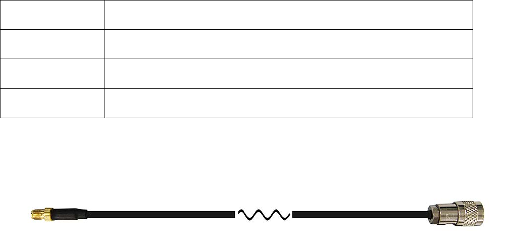
2.4.3 Feeding line(optional)
Image 2-6 schematic diagram of feeder line
RF cable TNC(Reverse polarity, internal thread, inner pin) connector connect with
reader antenna TNC connector, RF cable SMA connector connect with external circular
polarization antennas SMA connector, cable maximum length is 5m, impedance 50Ω,
insertion loss is less than 2dB, or you also can choose a high performance cable,
appropriate increase in length, insertion loss is less than 2dB.
Note: If Ultra long RF cable or the cable joint is not contacted well, may cause
performance deterioration on the read and write because of the emission signal and the
received echo signal’s attenuation.
2.4.4 Network connection diagram
Network interface used for long-distance high-speed connection (less than 80 m), can be
connected with the switcher or router through the network cable, or directly connected
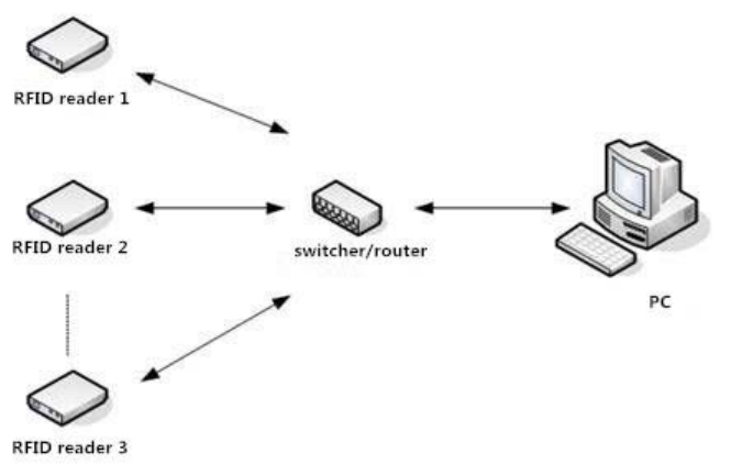
13
with the PC network interface, as shown in figure 2-7:
Image 2-7 Network application connection diagram
14
3. Installation
3.1 Notes
To ensure the normal and stable operation of the device and your personal property and
safety, please carefully read the following notes before install CL7206C reader and writer:
1. Firstly, check whether the power socket is connected to the ground, and to see whether
the local power supply voltage is in accordance with the applicable voltage range of the reader;
2. Check the device and the external connection if is closely connected;
3. Pay attention to the type selection and the length limit of the cable and the serial line:
Network cable connects directly, no longer than 80 meters
Serial line connects directly, no longer than 10 meters
4. When installing several readers, the antenna position and the antenna spacing should be
appropriate to avoid interference with each other.
3.2 Installation conditions
Before installing the reader, please carefully check if the product is in good condition, the
accessories are complete or not, if there is any damage, please contact the supplier.
3.3 Device connection
3.3.1 Power on
Insert the power cord into the AC power supply socket and plug another end into the
power connector of the device and tighten.
Turn on and wait about 20 seconds, the system initialization process is completed and is
standby state.
15
3.3.2 Antenna connection
The device built with four TNC coaxial cable connector for connecting an external antenna,
select low consumption RF cable, connectors should be tightened (Ensure to be waterproof
when install outdoors);
The reader antenna angle or corner to adjust to the best position through the actual test
according to the specific application,.
3.3.3 PC connection
The device provides special adapter cable, including interface of network, serial and power;
RS232 interface is for short distance communication (less than 10m), through the DB9
connector and the PC serial port connection to realize the communication of PC and the device.
RJ45 network port used for long distance communication (less than 80m), connect PC with
extend cable.
3.4 Device installation
The reading and writing range of the reader depends on the onsite application, the tilt angle
of the antenna is adjusted to achieve the best reading and writing performance.
3.5 Acceptance
Mainly from two aspects of acceptance criteria: structure and performance.
3.5.1 Acceptance of structure
Check below details:
Whether reader is fixed firmly, without loose;
Whether the cable connected firmly ;
16
Whether the screws are tighten
3.5.2 Performance acceptance
Whether the reader is working properly;
Whether the read and write range is reasonable.
17
4. Software operating
4.1 Demo software
The demo software mainly carries on system control, communication mode selection,
parameter setting and searching, read and write tags and data presentation and so on.
Before using the demon software, please check if the connection of the reader hardware is
completed, mainly ensure the following tips:
1, If the reader and computer serial port (network or RS485) is connected correctly
2, If the antenna ports have been connected to the antenna (ANT, ANT1 2, ANT 3, ANT totally
four ports)
3, If the reader and writer start up (hear "drop" buzzer sound).
4.2 Application environment
The software environment
Windows 2000 Service Pack 3、 Windows Server 2003、Windows XP Service Pack 2、
Windows 7 system
The hardware environment
P4/1.7GHz above PC, 512M or more memory, 40GB hard drive
4.3 Software version
V2.0.2
4.4 Installation
1. Copy the software to the PC, open the software installation package, double click “setup”
application, and follow the installation guide.
2. Click the next step, and select the installation path, click next, and the software will begin to

18
install.
3. Click the "Install", and software installation progress takes about 1mins.
4. After the progress of the software is finished, click the "finish" button to complete the
installation.
4.5 Operation
4.5.1 Device connection
All functions can be operated only after successful connection.
4.5.1.1 Serial communication connection
Double click the icon to start the Demo software, the main interface of the toolbar
icons are gray means reader is not connected, in the ‘connecting reader’ option list select
communication mode ‘serial connection’, ‘connection parameters’ select ‘COM?’
(choose PC serial number), communication baud rate select 115200 (default), click
“OK“ button, as shown in image
4-6.
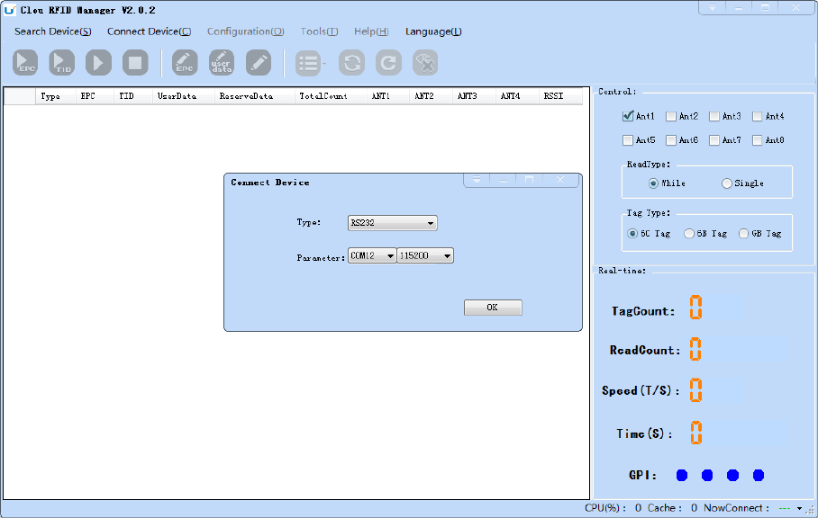
19
Image 4-6 Serial communication connection
If the connection is successful, all the icons in the toolbar are illuminated, as shown in
image 4-7, means the serial communication connection is successful.
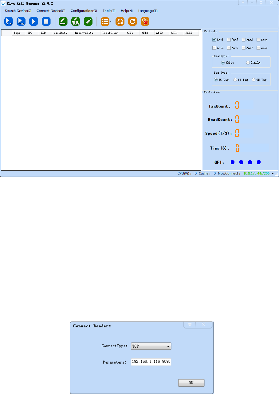
20
Imag4-7 serial port communication connect successful
4.5.1.2 Network port communication connection
Network port used for long distance connection (within 80 m), connect to the router
through cable and switcher, router, or connected with the PC network port directly. Select the
communication mode "TCP connection" in the "connect reader" option list, "connect
parameter" input reader IP (default 192.168.1.116), enter the communication port number
(default 9090), and click OK button, as shown in image 4-8
21
Image 4-8 Network port communication connection
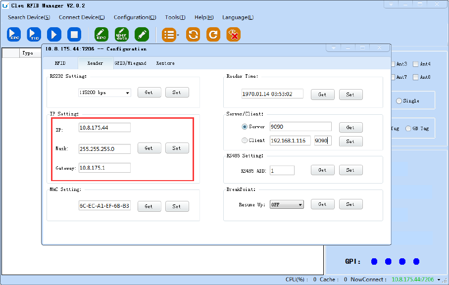
The device has been written IP address 192.168.1.116 as default. If you forget or need to
modify, using serial connection "connection" after connect successfully, then you can found the
current IP address through select “settings” > "senior" > “configuration”, set up the IP
address in “Network port settings” when “configuration” dialog pops up. See image 4-9
Note: The IP address of the reader can’t be repeated. Use the Ping command to test
whether the network is connected on PC.
image 4-9 reader configuration
4.5.1.3 RS485 communication connection
Select the communication mode in the "connect to the reader" option "485 connection
(serial port)", "connect parameter" select "COM?" (select PC serial number), communication rate
select "115200", enter the RS485 address, then click OK, as shown in image 4-10.
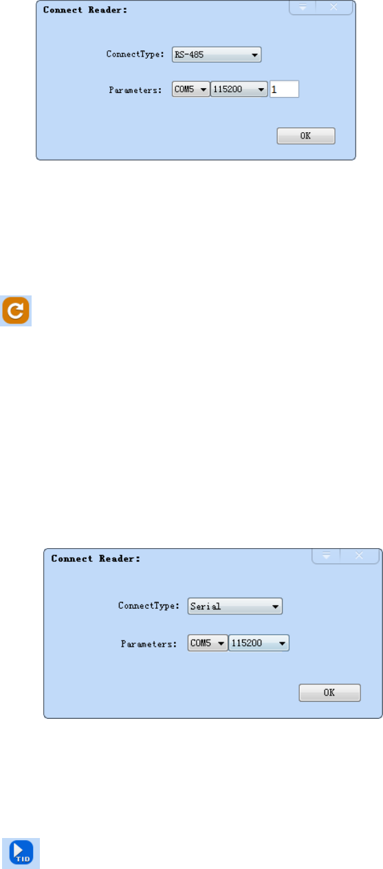
22
Image 4-10 485 communication connection
RS485 address defaults to 1
RS485 address range 1~255
Note: Click the button after changing the configuration
4.5.1.4 USB communication connection
Select the communication mode "serial port" in the "connect
reader" option list, "connect parameter" select "COM?" (the USB
serial number detected by PC), the communication rate is selected
"115200" (the default value), and click OK button, as shown in image
4-11.
Image 4-11 USB communication connection
4.5.2 Data display area
Click the button ,the data display area will show as image 4-12
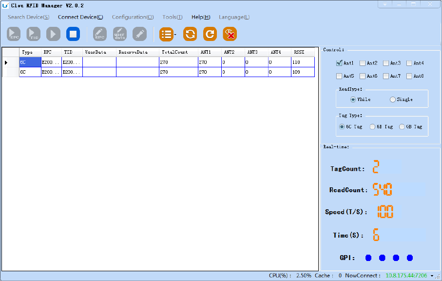
23
Image 4-12 data display area parameter meanings
Type: label type: 6C, 6B two types
EPC: EPC data of tags, can be read and write.
TID: the TID data of the label, the only logo, read only
User Data: user data area, can be read and write.
Reserve Data: reserved area data, store the password data, etc.
Total Count: total number of tags
ANT1: the reading times of NO.1 antenna
ANT2: the reading times of NO.2 antenna
ANT3: the reading times of NO.3 antenna
ANT4: the reading times of NO.4 antenna
RSSI:Signal Intensity
4.5.2.1 Read EPC

24
Click the button , the data display area will display the current read EPC data
EPC display as hexadecimal character string, use the word as length unit (1 word = 2 bytes = 4
hexadecimal character)
If you want to read the EPC data of the custom length, please refer to chapter 4.5.2.3 custom
read
4.5.2.2 Read TID
Click the button , the data display area will display the current read EPC and TID data
TID data display as hexadecimal character string, use the word as length unit (1 word = 2
bytes = 4 hexadecimal character).
TID length, the default is 6 words.
If you want to read the TID data of the custom length, please refer to chapter 4.5.2.3 custom
read
4.5.2.3 Custom read
Click the button , pop-up dialog box, as shown in Image 4-13
Select "6C tag configuration"
Matching read, you can matching read through known EPC data or TID data of tags.
Read TID, select to read the tag TID data, the read mode default as "adaptation", use the word
as length unit.
Read the user area, select to read the tag user area data, use the word as the starting address
and read length unit
Read the reserved area, select to read the tag retains data, use the word as the starting
address and read length unit
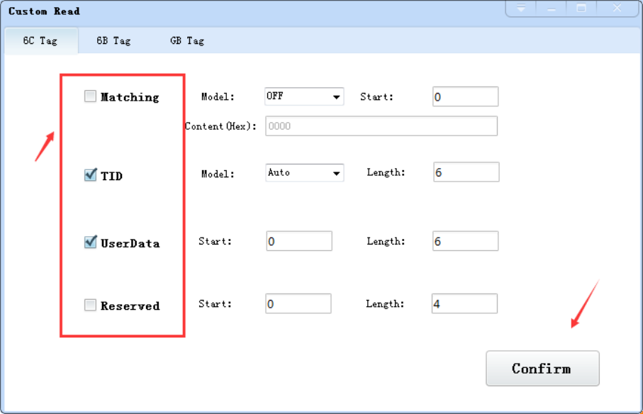
25
Image 4-13 6C Tag custom configurations
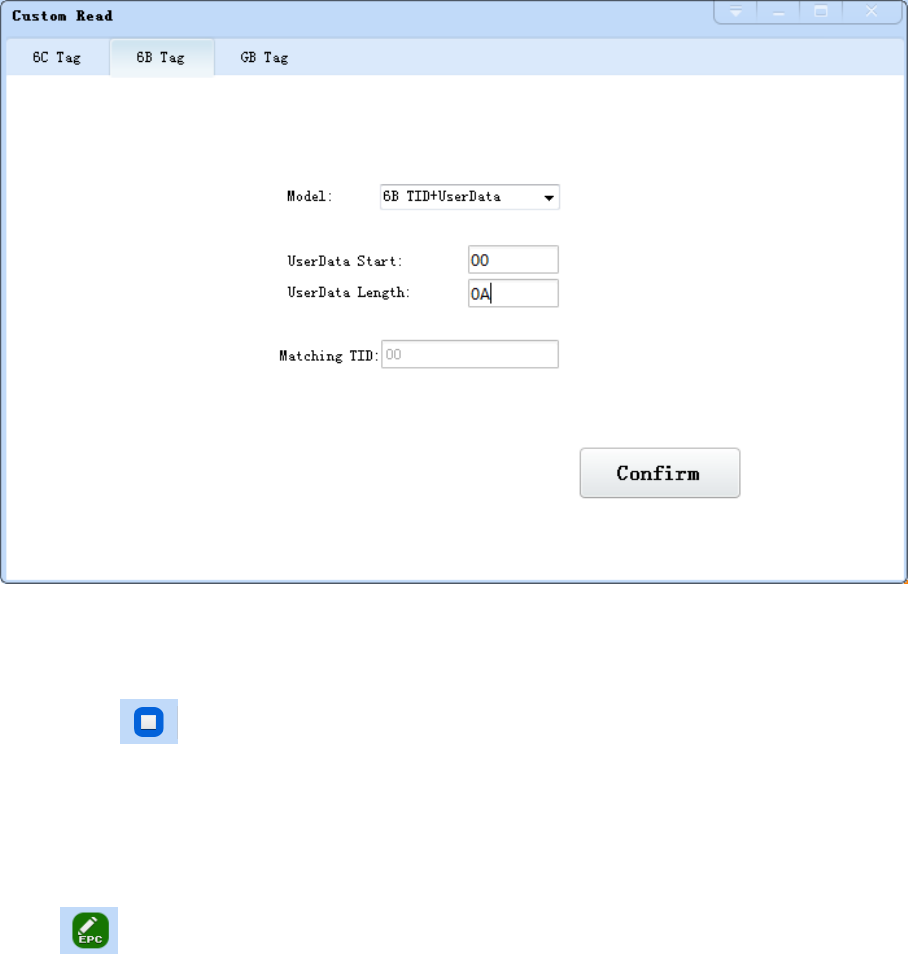
Select the 6B tag configuration, and pop up dialog box as shown in image 4-14
Can choose to read TID data or user data
Can matching read TID data.
Tip: Customer who not familiar with the label agreement, please ignore this feature
26
Image 4-14 6B Tag custom configurations
4.5.2.4 Stop read
Click button stop all read and write operations.
4.5.3 Write data
4.5.3.1 Write EPC data
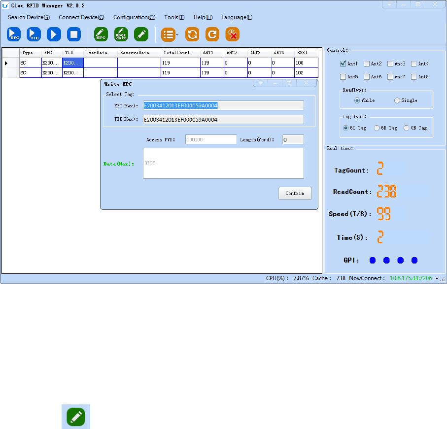
Click button and pop up dialog box as shown in image 4-15:

27
Image 4-15 write EPC data
Select a label data (contains TID information) has been read, fill in the EPC data (16 hex string),
click "OK".
4.5.3.2 Write user data
Click button and pop up dialog box as shown in image 4-16:
28
Image 4-16 write user data
Select a label data (contains TID information)has been read, fill in the user data (16 hex string),
click "OK".
4.5.3.3 Custom tag action
Click button and pop up dialog box as shown in image 4-17:

29
Image 4-17 Custom tag action
1. Select a tag data that has been read;
2. Click the "custom operation" button;
3. Take detailed action to write / lock / destroy tag according to the reader protocol
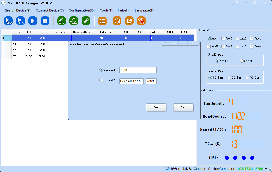
4.5.4 TCP server / client mode
Select configuration on the main demo interface > "read and write configuration >" TCP
server / client mode ", pop-up dialog box, as shown in Image 4-18:
30
Image 4-18 Mode setting
When the reader is configured as a "server" mode, the connection is initiated by PC; when
the reader set as a "client" mode, it will connect to the PC side automatically.
4.5.5 Antenna configuration
Select" configuration" on the DEMO main interface-- > "senior"-- > "reader configuration ",
then pop-up dialog box, as shown in image 4-19.
31
Image 4-19 Antenna enable configuration
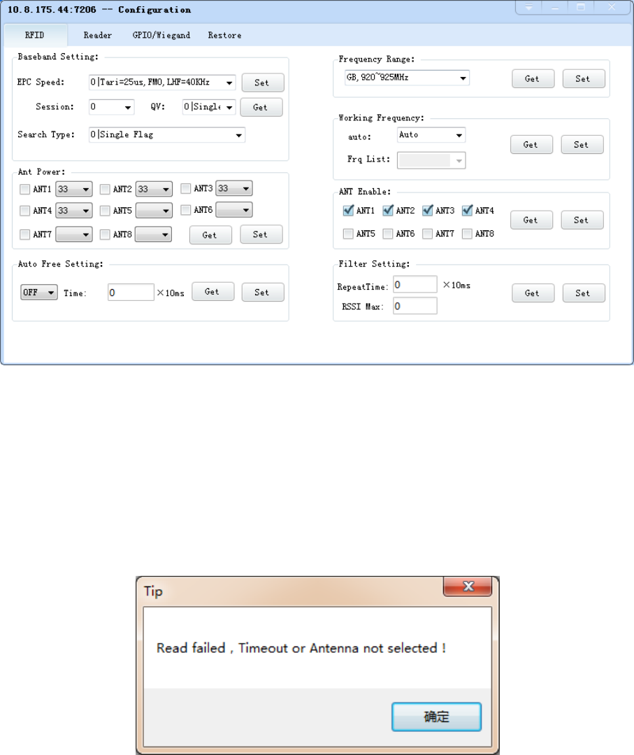
Select all antenna enable configuration, click the "configuration", pop up dialog box, click
"OK" means configure succeeds. If the antenna enable is not selected, when select the
corresponding reader on the DEMO main interface, will pop up dialogue box as shown in image
4-20.
Image 4-20 Antenna selection
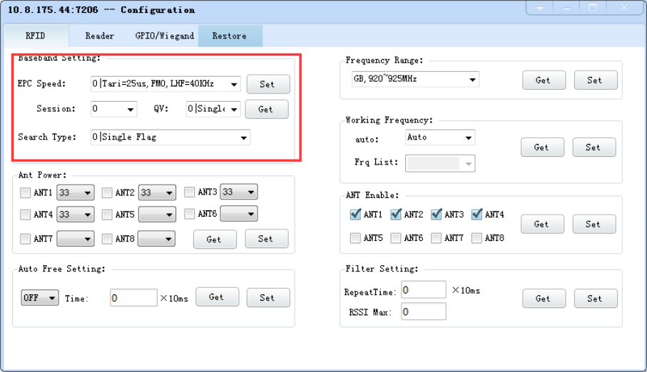
4.5.6 Base band parameter configuration
Select "configuration" on the DEMO main interface --> "senior" --> "reader", then pop-up
dialog box, as shown in image 4-21.
32
Image 4-21 Base band parameter configuration
Changing the base band parameter configuration can change the actual effect of the read
and write (can be reasonably configured according to the application scenarios, but it needs to
be operated under the guidance of our engineers).
EPC base band rate provides five options: Tair=25us, FM0, LHF=40KHz, dense reading mode;
Tair=25us, Miller4, LHF=300KHz; fast reading mode; 255/OUTO.
Session four choices: 0; 1; 2; 3.
Q values provide sixteen options: 0/ single label; 1; 2; 3; 4/ multi label; 5; 6; 7; 8; 9; 10; 14; 11;
12; 13; 15.
There are three options for searching tags: one side search; inventory only with Flag B;
double search.
4.5.7 Antenna port power setting
Select "configuration" on the DEMO main interface --> "senior" --> "reader", pop-up
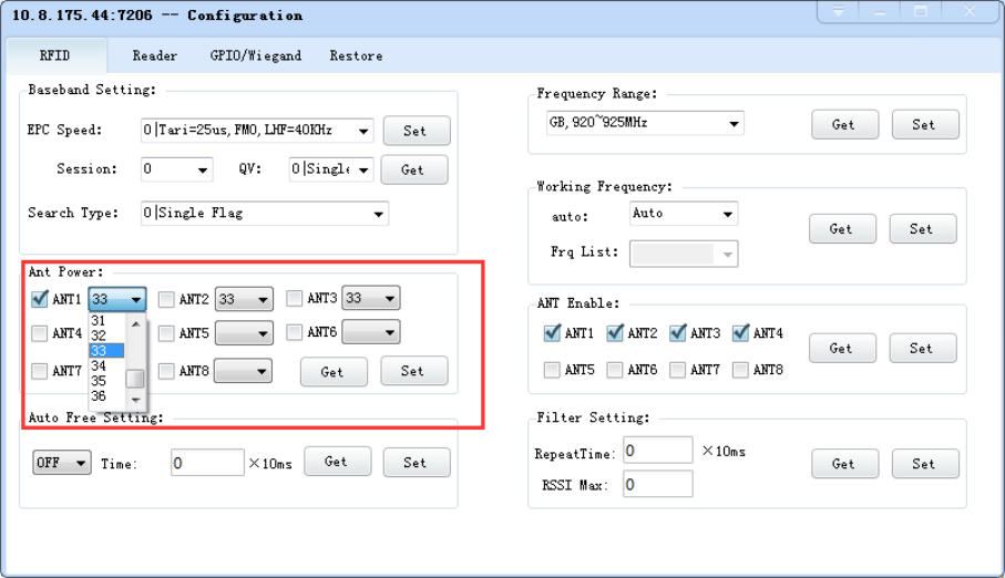
33
dialog box, as shown in image 4-22.
Image 4-22 Antenna port power setting
Select the corresponding antenna port (external antenna connected), select the appropriate
power values from the power list, click Configure, pop up the configuration of the success of the
dialog box, click OK to complete power configuration.
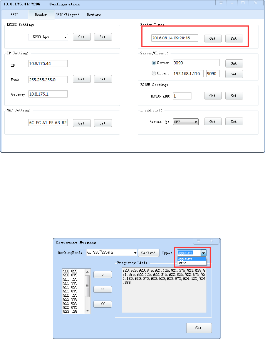
4.5.8 Clock setting
Select "configuration" on the DEMO main interface --> "senior" --> "reader configuration",
then pop-up dialog box, as shown in image 4-23. The current time of the reader can be check in
the area of the “reader time”. If you need to modify the reader time, modify the “reader
time” then click “configuration” button, pop-up dialog box then click OK.
34
Image 4-23 Clock display setting
4.5.9 Frequency Hopping
Click “configuration” on the main interface > RFID configuration > "hopping
management", pop-up frequency hopping management dialog box, as shown in image 4-24
Imag 4-24 Frequency Hopping management
Select "CMII, 920-925MHz" (see Image 4-25) in the "working band" drop-down list, click the
"Settings", select single frequency points from the left frequency list box(see Image 4-24) then
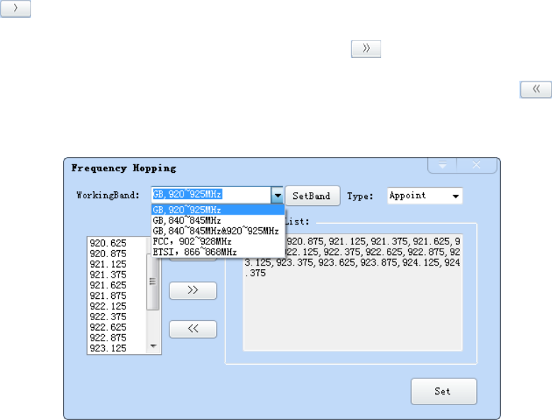
35
click the " " button, right into the list box, and then click the "configuration" to confirm; If
you want to select the full band frequency hopping just click all the frequency points will
show on the right side of the list box, click the "configuration" to confirm. If you click , all
frequency points on the right side of the list box will be cleared.
Image 4-25 Frequency Band selection
Note: The purpose of setting up the "automatic" is to avoid the interference of the external
signal and select the fast frequency hopping. The default configuration for general application
is automatically (as shown red mark dropdown list in image 4-24).
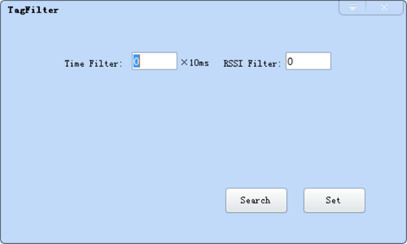
4.5.10 Label filtering
Select "configuration" on the main interface > "RFID configuration" > "label filter", then
pop-up dialog box, as shown in image 4-26:
36
Image 4-26 label filtering
Filtering time: indicates that the same label content within a specified period of time within
a read card instruction is only uploaded once, 0~65535, and time units: 10ms.
RSSI threshold: When label RSSI value small than the threshold value, the label data will not
be uploaded and discarded.
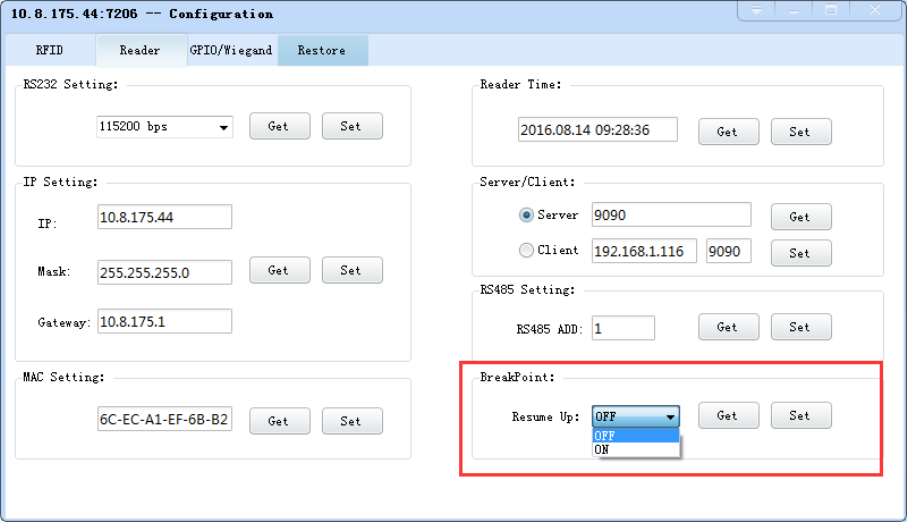
4.5.11 Buffer and breakpoint resume
For make sure the reader ‘s complete collection of rfid tags’ data, CL7206C support tag
data-caching mechanism and breakpoint resume, in case that the tag’s data loss because of
the communication interrupted or PC application error exit, the tag data by caching mechanism
could be saved without power.
Data caching mechanism mode’s start:
Main manu’s setting Advanced Reader setting Breakpoint, choose “ON” then it
will validate the function of tag’s caching mechanism. As image 4-27 shows.
37
Image 4-27 tag filter
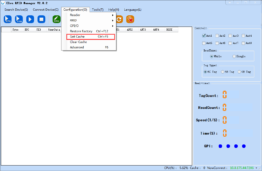
After the validate the breakpoint resume function, the PC will reply each data of tags
uploading, reader will automatically save the tag’s data which are not uploaded. PC could
operate the saved data through setting Obtain saved data or setting clear saved data. As
below image 4-28.
38
Image 4-28 tag buffer data operation
As under the breakpoint resume mode, PC will confirm to each tag data from reader, under
mass quantity of
tag data will reduce the communication efficiency, increase the system load, we suggest:
When start the breakpoint upload functions, according to your application, can set up
suitable “tag filter parameter” “filter time” to reduce the extra data uploading.
4.5.12 Auto idle set up
Select "configuration" on the main interface > "RFID configuration" > "auto idle ", then
pop-up dialog box, as shown in image 4-29:

39
Image 4-29 Auto idle configuration
Auto idle mode means when the reader continuous reading tags, all using antenna didn’t
identify the tags for three times continuously ,then the reader automatically enter a period of
idle state to save power consumption, the reader re-enter the card reader automatically after
idle time.
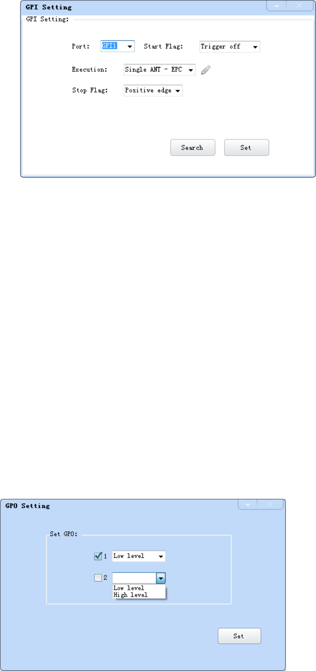
4.5.13 GPI/O configuration
GPI/O control is to provide the query and set up the I/O port state, control the function of the
I/O device.
GPI configuration
Select “configuration “on the main interface --> "GPI/O configuration" --> “GPI
configuration "then pop-up dialog box, as shown in image 4-30:
40
Imag 4-30 GPI configuration
Check: check the various port trigger parameters
Configuration: select the port need to set, click button to execute the settings after modify
Trigger start condition: select the mode from the drop-down list
Trigger execution instruction: select the mode from the drop-down list
Trigger stop condition: select the mode from the drop-down list
Description: when the start condition is satisfied, the reader will perform the configuration
of the reader/ writer command.
GPO configuration
Select “configuration” on the main interface > "GPI/O configuration" > " GPO
configuration "then pop-up dialog box, as shown in image 4-3:
41
Image 4-3 GPO configuration
CL7206C reader only supports four GPO outputs, that is "1" “2”, “3”, “4”.
Select the high / low level, click this configuration to execute settings after modify.
4.5.14 Others
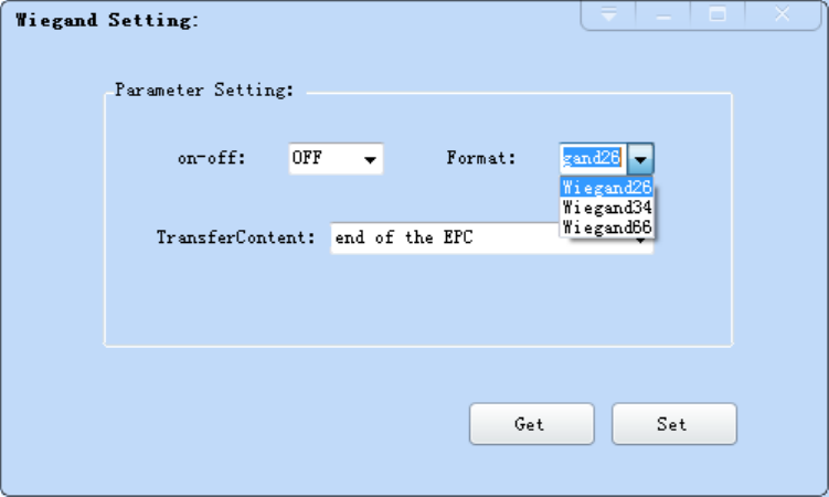
Wigand configuration
Select “configuration” on the main interface --> "GPI/O configuration" --> “Wigand "then
pop-up dialog box, as shown in image 4-30:
Image 4-30 Weigand configuration
In the Weigand parameter settings area, set up the “communication switch” for the "open"
state, and select the corresponding "communication format" and "transmission data content",
click on the "configuration" to determine.
Weigand port Parameter configuration: includes “Weigand 26, “Weigand 34" and
42
“Weigand 66"models.
Weigand 26: TID or EPC data reported from the end of the Weigand port is valid for 3 bytes.
Weigand 34: TID or EPC data reported from the end of the Weigand port is valid for 4 bytes.
Weigand 66: TID data reported from the end of the Weigand port is valid for 8 bytes.
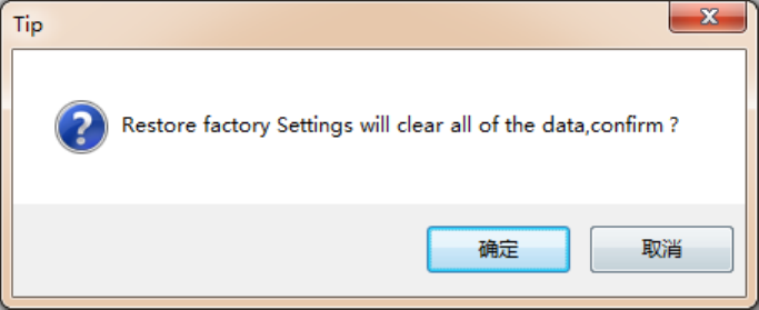
Restore factory settings
Select “configuration” on the main interface > “restore factory settings” then pop-up
dialog box, as shown in image 4-31:
Image 4-31 restore factory settings
When connected to the reader in any form, click OK button, and all settings of the reader
will be restored to the factory setting.
4.5.15 Tools
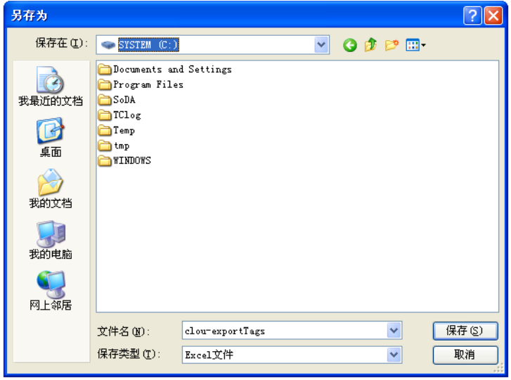
Data export
Select "tools" on the main interface > "data export" > "form (*. XLS), in the pop-up dialog
box, as shown in image 4-32, select the required export file save path.
43
Image 4-32 Data export
Read the tag data to support data export, export format can be.csv (comma file) and.Xls (Excel).
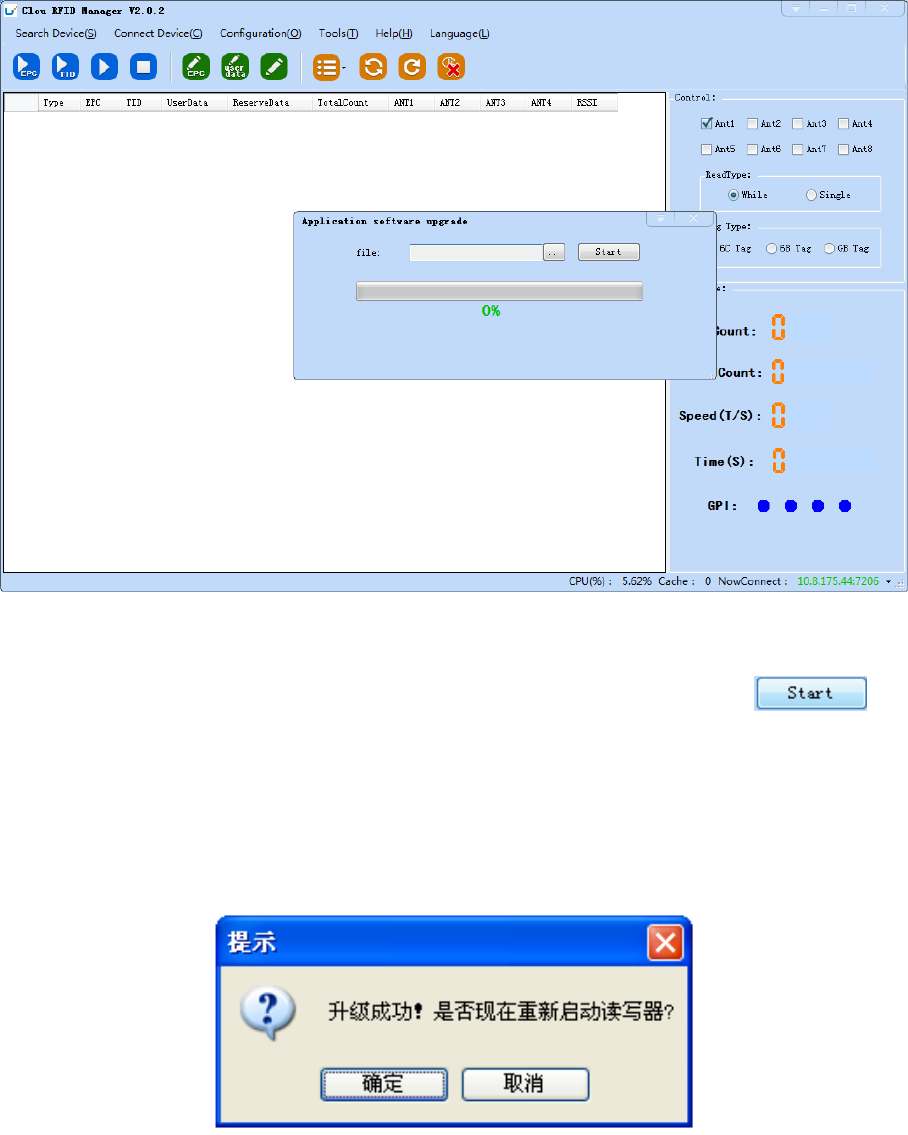
Software upgrade
The reader support for online upgrade, software upgrades support the baseband software
upgrade (the underlying software) and application software upgrades (system software
applications). Select "tools" on the main interface > "software upgrade" > "software", the
pop-up dialog box, as shown in image 4-33:
44
Image 4-33 Application software upgrade
To find the Bin upgrade file path in the upgrade file drop-down list, click the
upgrade progress bar shows 100% that means the application software upgrade successfully,
pop-up upgrade prompted success dialog box, click OK to restart the reader, as shown in image
4-34.
Image 4-34 Software upgrade successfully
The process of the application of the base band software is the same as that of the
application software.
45
5. Common failures
5.1 Daily maintenance
The routine maintenance of CL7206C usage:
☆To check whether the tightening of RF connector
☆To check if the screw fixed reader and antenna is loose
☆To check whether the RF cable joints appear outsourcing breaking the shielding layer
☆To check if the reader power line connection is reliable
5.2 Common failure analysis and solution
Power supply system failures:
Check whether the power adapter is normal, and the AC supply voltage is between 100V ~
240V.
The panel indicator light failed when power on:
Check whether the communication is normal; please contact customer service if it’s not
normal.
The serial port unable to connect:
Check if the serial cable is not connected or connected unstable.
Check if the serial port connect baud rate of the reader is correct
Check if the selected COM port is right.
The network port cannot connect:
Factory set the default IP address: 192.168.1.116 when CL7206C reader device ex-factory,
ensure the IP address of the PC and reader in the same network segment, such as
"192.168.1.XXX" then you can connect to the reader, if you forget the IP address of the device,
46
you can reset the reader’s IP address through the serial port.
The reader can't read the tag
Check if the setting of antenna number is correct
Check if the label is damaged
Check if the label is placed in the reader's valid reading and writing range.
Check if the electromagnetic interference between the reader and the other device.
For the problem users cannot solve, please contact customer service.
47
6. Package
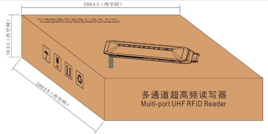
6.1 Package
Imag6-1 Carton box size
Carton box size: 290X290X76MM
6.2 Accessories
In order to facilitate the storage and transportation in near future, the packing box and the
packing material should be kept properly after unpack.
Besides of the device in the box, accessories equipped with the reader are also included in,
please check the product packing list to confirm whether the product and accessories are
complete, if any discrepancies or damage, please contact with the after-sale service in time.
The specific list of accessories as shown in table 6-1

48
Table 6-1 Package list
6.3 Storage environment
CL7206C fixed reader should be stored in below conditions:
NO. Name Material Code Qty Unit Remark
1 CL7206C Four-port fixed reader —————— 1 set Included
2 Power adapter 24V/2.5A 20109000000324 1 pcs Included
3 AC power cord 20350000000195 1 unit Included
4 Network cable 20350000000188 1 unit Included
5 RS232 blackcable 20351000000478 1 pcs Included
6 USB cable 20351000000036 1 pcs Included
7 9dBi circularly polarized antenna 20351000000035 4 pcs Optional
8 Feeder line SMA-K--TNC-J reversed polarity 20351000000814 4 pcs Optional
9 Mounting screws M4*28 W01-104028-100 4 pcs Included
10 Warranty card 20420000001651 1 pcs Included
11 Certificate of approval 20420000001650 1 pcs Included
12 CD N10-010000-002 1 pcs Optional
49
☆ Environment temperature:-40℃~+85℃
☆ Relative humidity:5% RH~95%RH

50
DECLARATION OF CONFORMITY
Hereby,Shenzhen Clou IOT Technologies Co.,Ltd. declares that this Integrated Fixed Reader
product in compliance with the essential requirements and other relevant provisions of
Directive 1999/5/EC. A copy of the Declaration of Conformity can be found an Website:
http://www.clouiotech.com/
Testing standards:
EN 60950-1:2006 + A11:2009 + A1:2010+A12:2011+A2:2013
EN 62311:2008
EN 301 489-1 V1.9.2(2011-09)
ETSI EN 301 489-3 V1.6.1(2013-08)
EN 302 208-1 V2.1.1: 2015-02
EN 302 208-2 V2.1.1: 2015-02
Manufacturer's Name: Shenzhen Clou IOT Technologies Co.,Ltd.
RFID Reader
Trade Mark: N/A
Model number: CL7206C
This device was tested for typical body‐worn operations. To comply with RF exposure
requirements, a minimum separation distance of 50cm must be maintained between the
user’s body and the handset, including the antenna. Third‐party belt‐clips, holsters, and
similar accessories used by this device should not contain any metallic components. Body‐worn
accessories that do not meet these requirements may not comply with RF exposure
requirements and should be avoided. Use only the supplied or an approved antenna.
This device in compliance with the essential requirements and other relevant provisions of
Directive 1999/5/EC. All essential radio test suites have been carried out.
1. CAUTION : RISK OF EXPLOSION IF BATTERY IS REPLACED BY AN INCORRECT TYPE. DISPOSE

51
OF USED BATTERIES ACCORDING TO THE INSTRUCTIONS
2. The device complies with RF specifications when the device used at 50cm form your body
Care for the environment! Must not be discarded with household waste!
This product contains electrical or electronic components that should be recycled. Leave the
product for recycling at the designated station, e.g. the local authority's recycling station.
3. Adapter shall be installed near the equipment and shall be easily accessible.
4. The plug considered as disconnect device of adapter
FCC WARNING
This device complies with part 15 of the FCC Rules. Operation is subject to the condition that this
device does not cause harmful interference (1) this device may not cause harmful interference, and (2)
this device must accept any interference received, including interference that may cause undesired
operation.
Any changes or modifications not expressly approved by the party responsible for compliance
could void the user's authority to operate the equipment.
NOTE: This equipment has been tested and found to comply with the limits for a Class B digital device,
pursuant to Part 15 of the FCC Rules. These limits are designed to provide reasonable protection
against harmful interference in a residential installation. This equipment generates, uses and can
radiate radio frequency energy and, if not installed and used in accordance with the instructions, may
cause harmful interference to radio communications. However, there is no guarantee that interference
will not occur in a particular installation.
If this equipment does cause harmful interference to radio or television reception,
which can be determined by turning the equipment off and on, the user is encouraged to try to
correct the interference by one or more of the following measures:
-- Reorient or relocate the receiving antenna.
-- Increase the separation between the equipment and receiver.
-- Connect the equipment into an outlet on a circuit different
from that to which the receiver is connected.
-- Consult the dealer or an experienced radio/TV technician for help.
To maintain compliance with FCC’s RF Exposure guidelines, This equipment should be installed and
operated with minimum distance between 20cm the radiator your body: Use only the supplied
antenna.
FCC ID: 2AKAGCLOUIOTCL7206C
52
7. After-sale service
Letter to Customers
Since our aim is to continuously improve our products for better user experience, we may
modify the product characteristics, composition and design of circuits without given
notifications. Thus the real product may be not in accordance with this manual. Generally, we
will provide timely amendments to this manual. If it’s not provided timely, please consult our
service department.
Shenzhen Clou IOT Technologies Co., Ltd.
Tel of Sales Dept: 0755-36901039
Tel of Customer Service Dept: 0755-36901039
Email: RFIDoverseas@szclou.com
Guarantee card of Shenzhen Electrical Technology Co.,Ltd

53
Product Name Model No.
Product Code Level
Description of
troubles
User’s name Postcode
Contact person Contact no.
Address of factory: Block 3 of CLOU Electronics Industrial Park, Baolong Industrial City,
Longgang District ,Shenzhen, Guangdong, China (Interchange of Baolong road and Qingfeng
Road)
Post code: 518057 Customer service centre: +86-755-36901057
Warranty Description: In order to offer users better service, our company provide warranty
card with each device, please keep it to enjoy the service.
1, Products can replace free under conditions within one month after sale, in the precondition
of normal operation without repairing.
2, Free maintenance won’t be given under the following circumstance:
①The damage of the terminal caused by high voltage of the power grid.
② The damage caused by misuse or operated improperly.
③The damage caused by excessive vibration when user delivering.
3, The software of this product can be upgraded freely, users can be training in our company for
free.
4, Will be charge appropriately if the user don’t have a warranty card.
5, Users will need to fill out the warranty card for repair service, and sent back to CLOU.