Compex Systems WLE1216V520 WiFi Module User Manual WLE1216V5 20 rev2
Compex Systems Pte Ltd WiFi Module WLE1216V5 20 rev2
Contents
- 1. WLE1216V5-20-User Manual rev2
- 2. Users Manual_rev
- 3. Users Manual
- 4. Users Manual rev
WLE1216V5-20-User Manual rev2
wireless modules
Last Updated: 06/07/17
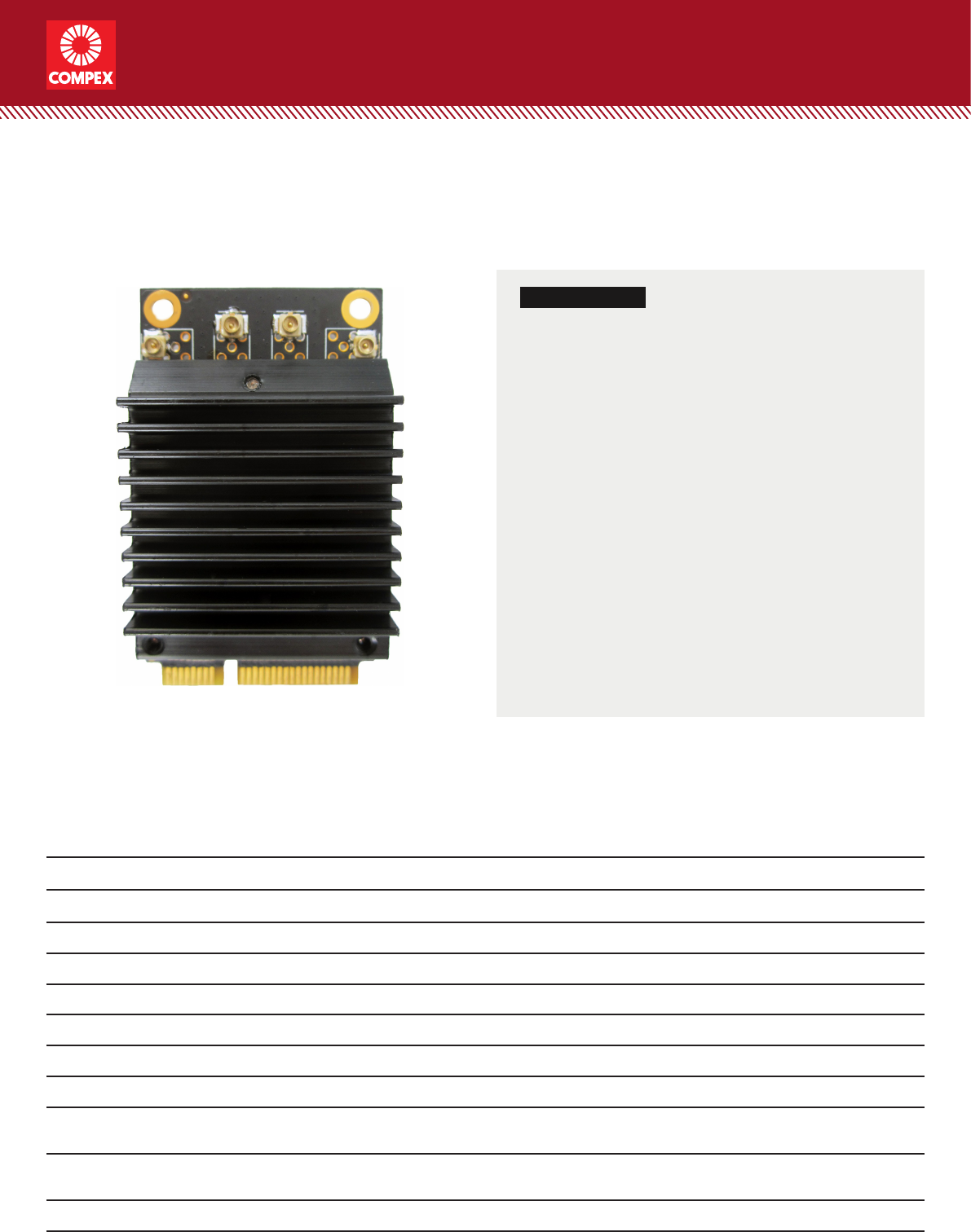
KEY FEATURES
• Qualcomm Atheros ‘Cascade’ QCA9984
•
• Heat sink allows free air operation
• IEEE 802.11ac compliant & backward compatible with
802.11a/n, up to 1733Mbps
• Multi-user MIMO (MU-MIMO)
• 4 spatial streams (4SS) at 80MHz
• 2 spatial streams (2SS) at 80+80MHz
• Mini PCI Express 2.0 interface
• Supports Spatial Multiplexing
Low-Density Parity Check (LDPC) Codes
Maximal Ratio Combining (MRC), Space Time Block
Code (STBC)
• Supports IEEE 802.11d, e, h, i, j, k, r, u, v time stamp, w ,
and z standards
• Supports Dynamic Frequency Selection (DFS)
• Designed for High Bandwidth Enterprise Wireless
Access Points
4x4 Wave-2 802.11ac/a/n Mini PCIe WiFi Module
Full size form factor with 80+80MHz bandwidth support
Specications
Chipset QCA9984
System Memory 256Kbit serial I²C bus EEPROM
Host Interface Mini PCI Express 2.0 Standard
Operating Voltage 3.3V
Antenna Connector 4x U.FL
Frequency Range 5.180 ~ 5.825 GHz
Power Consumption 8.5W (Max)
Modulation Techniques OFDM: BPSK, QPSK, 16-QAM, 64-QAM, 256-QAM
Supported Operating System CompexWRT
Temperature Range Operating: -20ºC to 70ºC
Storage: -40ºC to 90ºC
Humidity Operating: 5% to 95% (non-condensing)
Storage: Max. 90% (non-condensing)
ESD Sensitivity Class 1B
Dimensions (H x W x D) 50.8mm x 29.9mm x 12.9mm
Model: WLE1216V5-20
COMPEX SYSTEMS
PRELIMINARY
3
wireless modules
Compex Systems Pte Ltd | www.compex.com.sg | (+65) 6286 2086 | sales@compex.com.sg | Last Updated: 06/07/17 WH XG SB SY HB
Copyright © Compex Systems. All rights reserved. COMPEX and the COMPEX logo, are registered trademarks of Compex Inc.
Atheros and other trademarks are properties of their respective owners. While every effort is made to ensure the information is accurate,
Compex does not accept liability for any errors or mistakes that may arise. All specifications are subject to change without notice.
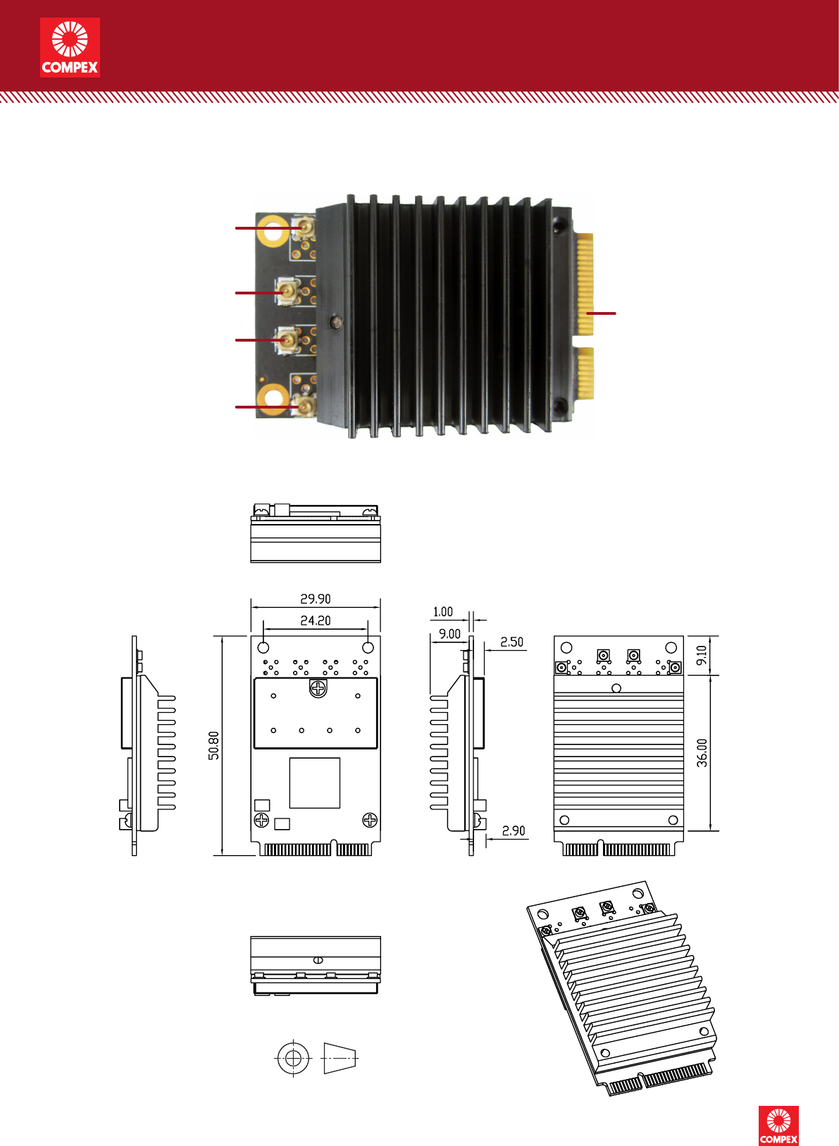
Mechanical Dimensions
Feature Guide
U.FL connectors
CH3
CH0
Mini PCIe 2.0
edge connector
CH2
CH1
COMPEX SYSTEMS
PRELIMINARY
4
wireless modules
Compex Systems Pte Ltd | www.compex.com.sg | (+65) 6286 2086 | sales@compex.com.sg | Last Updated: 06/07/17 WH XG SB SY HB
Copyright © Compex Systems. All rights reserved. COMPEX and the COMPEX logo, are registered trademarks of Compex Inc.
Atheros and other trademarks are properties of their respective owners. While every effort is made to ensure the information is accurate,
Compex does not accept liability for any errors or mistakes that may arise. All specifications are subject to change without notice.
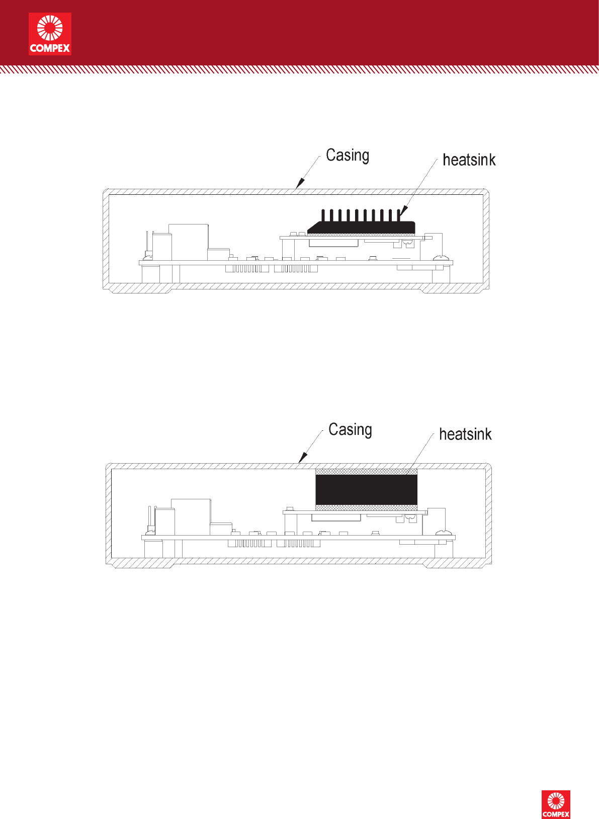
Heat Dissipation Options
Using the pre-installed heatsink for heat dissipation
Using a custom design metal enclosure for heat dissipation
COMPEX SYSTEMS
PRELIMINARY

5
wireless modules
Compex Systems Pte Ltd | www.compex.com.sg | (+65) 6286 2086 | sales@compex.com.sg | Last Updated: 06/07/17 WH XG SB SY HB
Copyright © Compex Systems. All rights reserved. COMPEX and the COMPEX logo, are registered trademarks of Compex Inc.
Atheros and other trademarks are properties of their respective owners. While every effort is made to ensure the information is accurate,
Compex does not accept liability for any errors or mistakes that may arise. All specifications are subject to change without notice.
Ordering Conguration
Item Code Chipset Form Factor Card Information
WLE1216V5-207A00001.01 QCA9984 Standard size card 4x4 802.11ac/a/n
5GHz Wave 2
Packaging Content
Item Quantity
WLE1216V5-20 Wireless Module 1
Packaging Information
Packaging Type Dimensions Weight Dimensional Weight
Packing Box (50 units) 385 x 207 x 76 mm 1.514 kg 1.5 kg
Carton Box
(5 packing boxes / 250 units) 422 x 410 x 240 mm 8.3 kg 9 kg
COMPEX SYSTEMS
PRELIMINARY
Compliance Information
FCC 15.105
For a Class B digital device or peripheral, the instructions furnished the user shall
include the following or similar statement, placed in a prominent location in the text of
the manual:
NOTE: This equipment has been tested and found to comply with the limits for a
Class B digital device, pursuant to part 15 of the FCC Rules. These limits are
designed to provide reasonable protection against harmful interference in a residential
installation. This equipment generates, uses and can radiate radio frequency energy
and, if not installed and used in accordance with the instructions, may cause harmful
interference to radio communications. However, there is no guarantee that
interference will not occur in a particular installation. If this equipment does cause
harmful interference to radio or television reception, which can be determined by
turning the equipment off and on, the user is encouraged to try to correct the
interference by one or more of the following measures:
—Reorient or relocate the receiving antenna.
—Increase the separation between the equipment and receiver.
—Connect the equipment into an outlet on a circuit different from that to which the
receiver is connected.
—Consult the dealer or an experienced radio/TV technician for help.
FCC 15.19
This device complies with Part 15 of the FCC Rules. Operation is subject to the
following two conditions:
(1) This device may not cause harmful interference, and
(2) this device must accept any interference received, including interference that may
cause undesired operation.
FCC 15.21
Any changes or modifications not expressly approved by the party responsible for
compliance could void the user’s authority to operate the equipment.
FCC 15.203
This equipment complies with FCC RF radiation exposure limits set forth for an
uncontrolled environment. This device and its antenna must not be co-located or
operating in conjunction with any other antenna or transmitter.
RF exposure warning
The antennas used for this transmitter must be installed to provide a separation
distance of at least 20 cm from all persons and must not be co-located or operating in
conjunction with any other antenna or transmitter.

OEM Integration Instructions:
This device is intended only for OEM integrators under the following conditions:
The module is only limited to installation in mobile applications. The antenna must be
installed such that 20 cm is maintained between the antenna and users,and the
transmitter module may not be co-located with any other transmit or antenna. The
module shall be only used with the integral antenna(s) that has been originally tested
and certified with this module.
As long as 3 conditions above are met,further transmitter test will not be required.
However,the OEM integrator is still responsible for testing their end-product for any
additional compliance requirement with this module installed (for example, digital
device emission, PC peripheral requirements,etc.)
IMPORTANT NOTE:
In the event that these conditions cannot be met (for example certain laptop
configuration or co-location with another transmitter), then the FCC authorization for
this module in combination with the host equipment is no longer considered valid and
the FCC ID of the module cannot be used on the final product. In these and
circumstance,the OEM integrator will be responsible for re-evaluating. The end
product (including the transmitter) and obtaining a separate FCC authorization
The final end product must be labeled in a visible area with the following: “Contains
Transmitter Module FCC ID: TK4WLE1216V520 or Contains FCC ID:
TK4WLE1216V520”
The module will be restricted on these host (Detail information show as below)
Manufacturer: Compex Systems Pte Ltd
Product name:Access Point
Product Model Number:WPJXXX
This host is used for point-to-point access point (client terminal) that will provide
network service through LAN port.
No. Antenna Manufacturer Frequency
Band
(MHz)
Max Peak
Gain
(dBi)
Wi-Fi External Antenna List (5GHz 4*4 MIMO)
1# Omni Directional Exceltek Electronics Technology
Co., Ltd.
2400 ~ 2500 3.0
5150 ~ 5850 5.0
2# Omni Directional Laird Smart Technology Co., Ltd. 2400 ~ 2500 2.2
5150 ~ 5850 3.5
3# Omni Directional Linx Technologies 2400 ~ 2500 2.5
5150 ~ 5850 4.6
4# Omni Directional Kenbotong Technology Co., Ltd. 5150 ~ 5850 10.0
Note 1: The device didn’t support beam-forming technology and Cyclic Delay Diversity (CDD)
technology, and the transmit signals are uncorrected, so no add array gain to the band power and
band PSD.
Note 2: We selected the max peak gain antenna 4# to perform all RF testing.