COMPUTIME AAHZT01 Digital ZigBee Thermostat User Manual
Computime Limited Digital ZigBee Thermostat
UserManual.wiki
>
COMPUTIME
>
AAHZT01 User Manual
User Manual
Navigation menu
Upload a User Manual
Namespaces
Wiki Guide
HTML
PDF
Info
Views
User Manual
Discussion / Help
Navigation


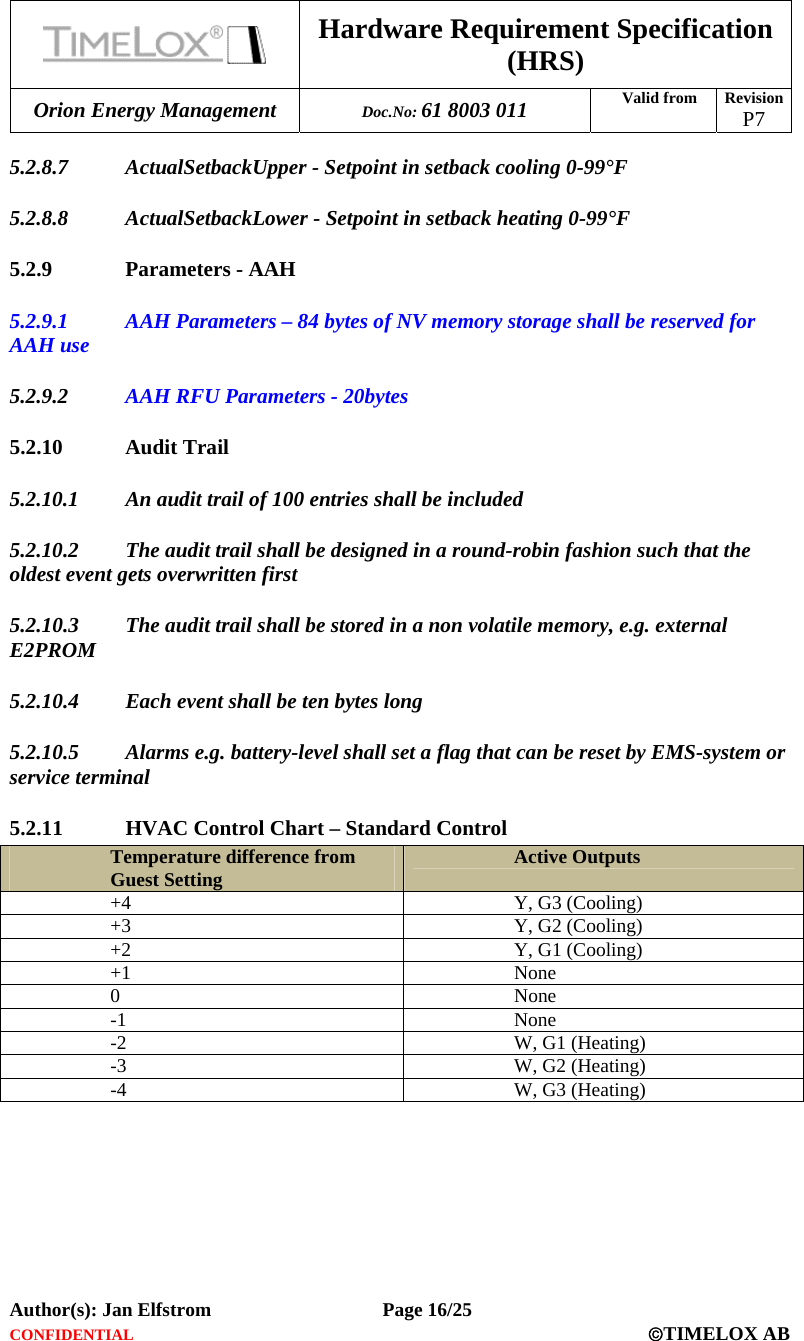
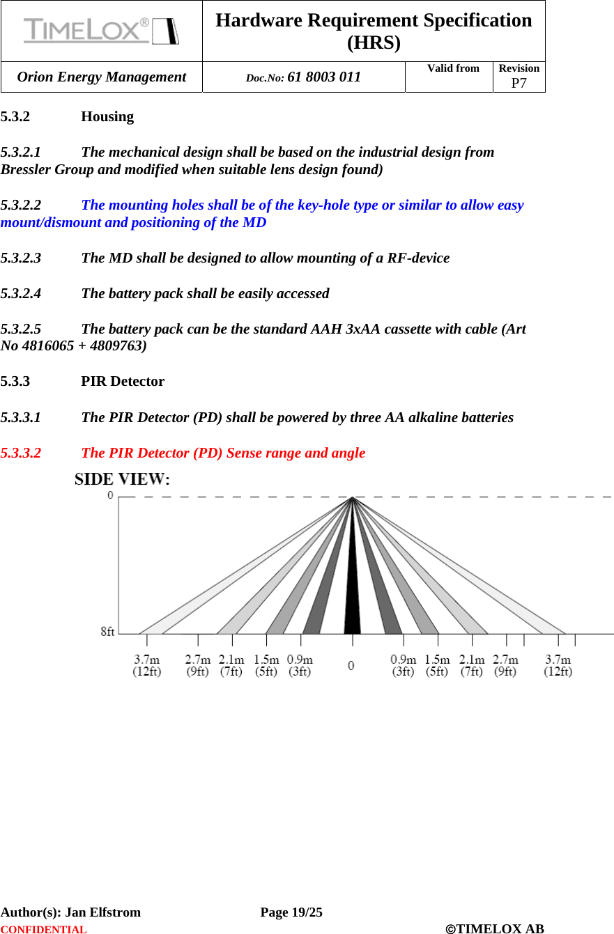
![Hardware Requirement Specification (HRS) Orion Energy Management Doc.No: 61 8003 011 Valid from Revision P7 Author(s): Jan Elfstrom Page 17/25 CONFIDENTIAL ©TIMELOX AB 5.2.12 Real Time Clock (RTC) 5.2.12.1 A RTC shall be designed based on a standard low power 32kHz crystal 5.2.12.2 The RTC function can be an internal MCU timer clocked by the low power crystal 5.2.12.3 Maximum time deviation over a year shall be +/-15 minutes 5.2.12.4 The minimum resolution shall be one minute 5.2.12.5 The real time shall be an incremental number with the length of four bytes 5.2.12.6 The start time for the real-time count (0) shall be 1996-07-20 00:00 5.2.12.7 No support for day-light saving shall exist 5.2.13 Counters 5.2.13.1 Counter for total HVAC run time [32-bit value, minute resolution] 5.2.13.2 Counter for HVAC run time maintaining the guest set-point (starts when guest set-point is first reached from set-back) [32-bit value, minute resolution] 5.2.13.3 Counter for total HVAC run time in unoccupied and unsold set-back including recovery time from setback to set point [32-bit value, minute resolution] 5.2.13.4 Counter for total occupancy time [32-bit value, minute resolution] 5.2.13.5 Three maintenance run time parameters [32-bit value, minute resolution] • tlmMaintenanceCounter1 • tlmMaintenanceCounter2 • tlmMaintenanceCounter3](https://usermanual.wiki/COMPUTIME/AAHZT01/User-Guide-1335284-Page-17.png)