COMPUTIME CTL2607 ZigBee-Ready RF Transceiver User Manual CTL2607 Product Specifications R1
Computime Ltd. ZigBee-Ready RF Transceiver CTL2607 Product Specifications R1
UserManual.wiki
>
COMPUTIME
>
CTL2607 User Manual
User manual
Navigation menu
Upload a User Manual
Namespaces
Wiki Guide
HTML
PDF
Info
Views
User Manual
Discussion / Help
Navigation
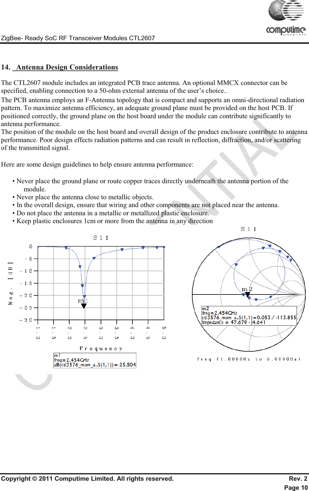
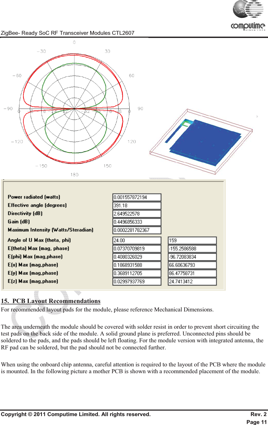
![ZigBee- Ready SoC RF Transceiver Modules CTL2607 Copyright © 2011 Computime Limited. All rights reserved. Rev. 2 Page 9 13. RF Frequency DetailThe following table shows the RF channels as defined by the IEEE 802.15.4 standard. RF channel Frequency 11 2405MHz 12 2410MHz 13 2415MHz 14 2420MHz 15 2425MHz 16 2430MHz 17 2435MHz 18 2440MHz 19 2445MHz 20 2450MHz 21 2455MHz 22 2460MHz 23 2465MHz 24 2470MHz 25 2475MHz 26 2480MHz The output power level of em250 can be configured in the range -32 to 4.5 dBm and the gain of FEM is 17dB, So the module output can controlled in range -15 to 20dBm. The RF transceiver uses direct sequence spread spectrum (DSSS) with 2 Mchip/s chip rate, giving a raw data rate of 250 kbit/s. The modulation format is Offset – Quadrature Phase Shift Keying (O-QPSK). It is robust even under noisy environments when sharing the same frequency band with other applications. Note: the output power of em260 should be configured lower than -15dBm for 2480M channel to Comply FCC The use of RF frequencies and maximum allowed RF power should according to different national regulations. The]CTL2607 is complying with the applicable regulations for the world wide 2.4GHz ISM band. [Subject to final approval: Specifically it complies with the European Union R&TTE directive meeting EN 300 328 and EN300 440 class 2. It also meets the FCC CFR47 Part15 regulations for use in the US and the ARIB T-66 for use in Japan.] -19dBm-20 to 19dBm](https://usermanual.wiki/COMPUTIME/CTL2607/User-Guide-2777992-Page-10.png)