G5LE 0813 1
G5Le 0813 G5LE_0813 G5LE_0813 [sku] product ation
G5Le 0813 G5LE_0813 G5LE_0813 assets.controlanything.com
G5Le 0813 0 G5LE_0813_0 G5LE_0813_0 assets.controlanything.com
2015-04-03
: Controlanything G5Le 0813 1 G5LE_0813_1
Open the PDF directly: View PDF ![]() .
.
Page Count: 6
PCB Relay G5LE 191
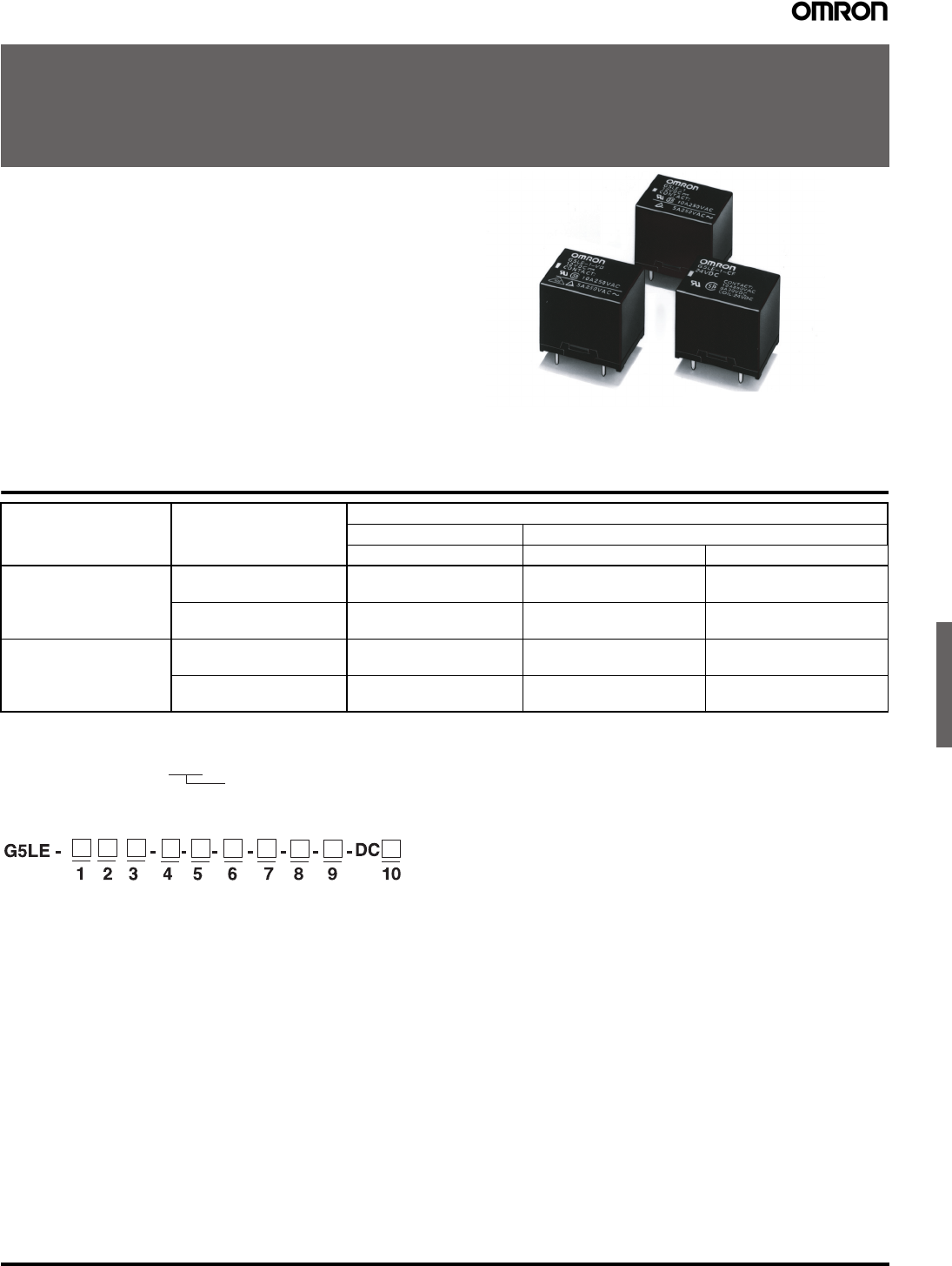
PCB Relay
G5LE
A Cubic, Single-pole 10-A Power Relay
• High Capacity (-E) versions
• Subminiature “sugar cube” relay with universal footprint.
• Conforms to EN 61810-1. UL recognized/ CSA certified.
• UL class-F coil insulation model available
(UL class-B coil insulation for standard model).
• Withstands impulse of up to 4,500 V.
• 400-mW and 360-mW coil power types available.
• RoHS Compliant
RC
VDE
X
Ordering Information
Model Number Legend
1. Number of Poles
1: 1 pole
2. Contact Form
None: SPDT
A: SPST-NO
3. Enclosure Ratings
None: Flux protection
4: Fully sealed
(Not applicable with -E versions)
4. Contact Material
None: AgSnO2(AgSnIn for -E versions)
ASI: AgSnIn
5. Insulation System
None: Class B (Class F for -E versions)
CF: Class F (UL and CSA only)
6. Classification
E: High capacity type
7. Coil Power Consumption/Coil Characteristic
None: Approx. 400 mW (Approx. 700mW for -G versions)
36: Approx. 360 mW (Not applicable for -G versions)
8. Approved Standards
None: UL, CSA, and VDE
9. Packaging
None: Standard polystyrene tray
SP: Anti-static tube packaging
10.Rated Coil Voltage
5, 9, 12, 24, 48 VDC
Enclosure ratings Contact form/Style
Contact material
AgSnO2AgSnIn
Standard Standard High Capacity
Flux protection SPDT G5LE-1
G5LE-1-CF
G5LE-1-ASI
G5LE-1-ASI-CF
G5LE-1-E
SPST-NO G5LE-1A
G5LE-1A-CF
G5LE-1A-ASI
G5LE-1A-ASI-CF
G5LE-1A-E
Fully sealed SPDT G5LE-14
G5LE-14-CF
G5LE-14-ASI
G5LE-14-ASI-CF
---
SPST-NO G5LE-1A4
G5LE-1A4-CF
G5LE-1A4-ASI
G5LE-1A4-ASI-CF
---
Rated coil voltage
Note: When ordering, add the rated coil voltage to the model number.
Example: G5LE-1 DC12
192 PCB Relay G5LE
Specifications
■Coil Ratings
400-mW Type
Note: The rated current and coil resistance are measured at a coil temperature of 23°C with a tolerance of ±10%.
360-mW Type
Note: The rated current and coil resistance are measured at a coil temperature of 23°C with a tolerance of ±10%.
■Contact Ratings
Note: Reference value-Plevel:λ60 =0.1x10
–6 operations
Rated voltage 5 VDC 9 VDC 12 VDC 24 VDC 48 VDC
Rated current 79.4 mA 45 mA 33.3 mA 16.7 mA 8.33 mA
Coil resistance 63 Ω200 Ω360 Ω1,440 Ω5,760 Ω
Must operate voltage 75% max. of rated voltage (max.)
Must release voltage 10% min. of rated voltage (min.)
Max. voltage 130% of rated voltage at 85°C, 170% of rated voltage at 23°C
Power consumption Approx. 400 mW
Rated voltage 5 VDC 9 VDC 12 VDC 24 VDC 48 VDC
Rated current 72 mA 40 mA 30 mA 15 mA 7.5 mA
Coil resistance 70 Ω225 Ω400 Ω1,600 Ω6,400 Ω
Must operate voltage 75% max. of rated voltage (max.)
Must release voltage 10% min. of rated voltage (min.)
Max. voltage 130% of rated voltage at 85°C, 170% of rated voltage at 23°C
Power consumption Approx. 360 mW
Standard G5LE-E
Load Resistive load (cosφ=1)
Rated load 10Aat120VAC;8Aat30VDC
10A at 240VAC (12 and 24 VDC coil)
16A at 250VAC
Contact Material AgSnO2(AgSnIn optional) AgSnIn
Rated carry current 10 A 16A
Max. switching voltage 250 VAC, 125 VDC
(30 VDC when UL/CSA standard is applied)
250VAC
Max. switching current AC: 10 A; DC: 8 A AC: 16A
Max. switching power 1,200 VA, 240 W 4,000VA
Minimum Permissible Load (See note) 100 mA at 5 VDC
PCB Relay G5LE 193
■Characteristics
■Approved Standards
UL Recognized (File No. E41643)
CSA Certified (File No. LR34815)
EN 61810-1, EN 60255, IEC (VDE TUV Reg No. R9151267, VDE Reg No. 6850UG)
Contact resistance 100 mΩmax.
Operate time 10 ms max.
Release time 5 ms max.
Bounce Time Operate: Approx. 0.6ms
Release: Approx. 7.2ms
Max. switching frequency Mechanical: 18,000 operations/hr
Electrical: 1,800 operations/hr at rated load
Insulation resistance 100 MΩmin. (at 500 VDC)
Dielectric strength 2,000 VAC, 50/60 Hz for 1 min between coil and contacts
750 VAC, 50/60 Hz for 1 min between contacts of same polarity
Impulse withstand voltage 4,500 V (1.2 x 50 μs) between coil and contacts
Insulation
Distance
Creepage (Typ) 3.3 mm
Clearance (Typ) 2.7 mm
Tracking Resistance (CTI) 250 V
Vibration resistance Destruction: 10 to 55 to 10 Hz, 0.75-mm single amplitude (1.5-mm double amplitude)
Malfunction: 10 to 55 to 10 Hz, 0.75-mm single amplitude (1.5-mm double amplitude)
Shock resistance Destruction: 1,000 m/s2
Malfunction: 100 m/s2
Endurance Mechanical: 10,000,000 operations min. (at 18,000 operations/hr)
Electrical: 100,000 operations min. (at 1,800 operations/hr) for standard type
36,000 operations min. (10A at 250VAC)
100,000 operations min. (at 1,800 operations/hr), 12A 250 VAC) - applicable for
G5LE-1-E,NO contact only
Ambient temperature Operating: −40°Cto85°C (with no icing)
Ambient humidity Operating: 5% to 85%
Weight Approx. 12 g
Model Coil rating Contact rating
G5LE 3 to 48 VDC
(Standard)
5to24VDC
(-E versions)
10 A, 250 VAC (general use), 6,000 cycles, 40°C (excluding -G type)
10 A, 125 VAC (general use), 100,000 cycles, 40°C (excluding -E, -G types)
8 A, 30 VDC (resistive load), 6,000 cycles, 40°C (excluding -E, -G types)
125 VA, 125 VAC, pilot duty, 100,000 cycles, 105°C (excluding -G type)
NO:
13 A, 120 VAC, resistive, 100,000 cycles, 85°C (AgSnO2& -E types, only)
1/2 hp, 125 VAC, 100,000 cycles, 40°C (excluding -G type)
1/3 hp, 125 VAC, 30,000 cycles, 70°C (AgSnO2type only, excluding -E, -G types)
400W-T (3.3A), 120 VAC, tungsten, 100,000 cycles (AgSnO2type only, excluding -E, -G types)
TV-5, 120 VAC, 40°C (-ASI type only, excluding -E, -G types)
12 A, 250 VAC, general use, 100,000 cycles, 1s=on, 1s=off, 105°C (-E type only)
TV-8,120 VAC, 25,000 cycles, 40°C (-E type only)
10 A, 35 VDC, resistive, 100,000 cycles, 1s=on, 1s=off, 40°C (-G type only)
NC:
12 A, 250 VAC, general use, 30,000 cycles, 1s=on, 9s=off, 40°C (-E type only)
10 A, 35 VDC, resistive, 50,000 cycles, 5s=on, 5s=off, 40°C (-G type only)
1/8 hp, 120 VAC, 50,00 cycles, 40°C (AgSnO2type only, excluding -E, -G types)
Model Coil rating Contact rating
G5LE Approx. 400 mW
3, 5, 6, 9, 12, 24, 48 VDC
Approx. 360 mW
5, 6, 12, 24, 48 VDC
10A, 250VAC (resistive load, 50,000 cycles at 85°C)
5A, 30VDC
2.5 A, 250 VAC (cosφ= 0.4)
194 PCB Relay G5LE
Engineering Data
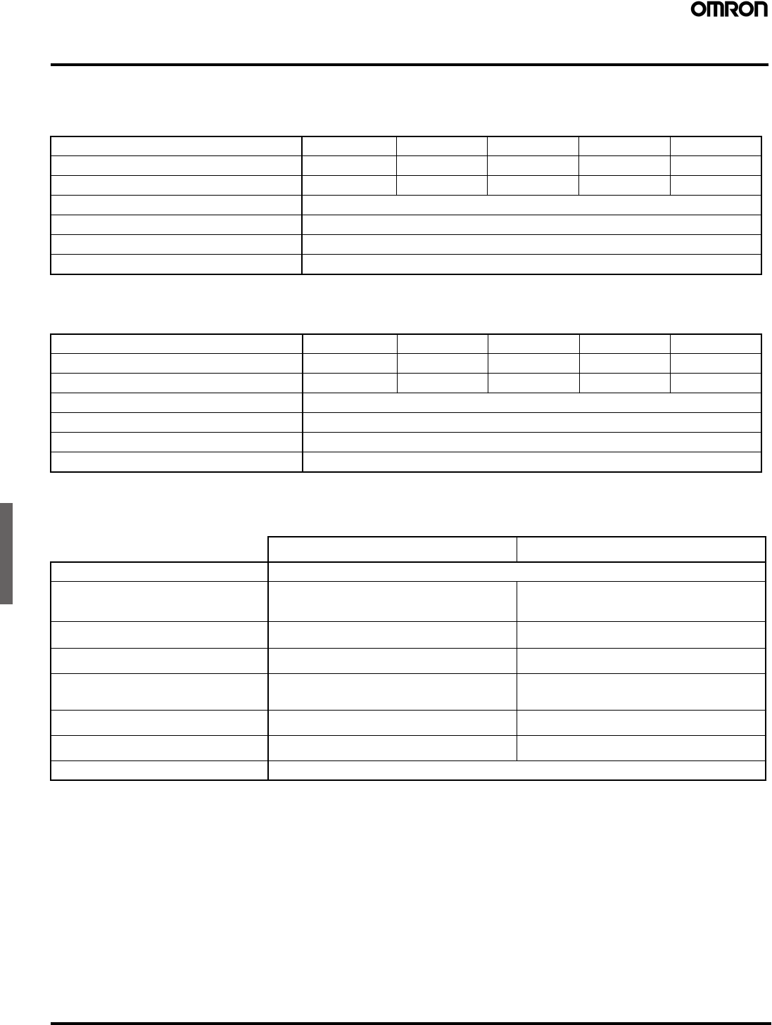
For standard type
For suffix -E
Switching current (A)
0.3
0.5
0.7
1
3
5
7
10
0
10
30
50
125
250
500
1,000
Switching Voltage (V)
DC resistive
load
AC resist ive
load
Life expectancy (x10
3
operations)
Switching current (A)
10
30
50
70
100
300
500
700
1,000
3,000
5,000
2
4
6
8
10
12
0
30VDC
resistive load
12 0 V A C inductive
CosØ=0.4
(see note)
120VAC
resistive load
30VDC
inductive
(L/R=7ms)
Maximum Voltage (%)
0
100
120
140
160
180
200
-25
20
30
40
50
60
70
80
90
100
23
Switching temperature (°C)
Max. Switching Capacity Life Expectancy Ambient Temp. Vs. Max. Voltage
Note: Same curve as for 250-VAC
resistive load
Note: The maximum coil voltage refers
to the maximum value in a varying
range of operating power voltage,
not a continuous voltage.
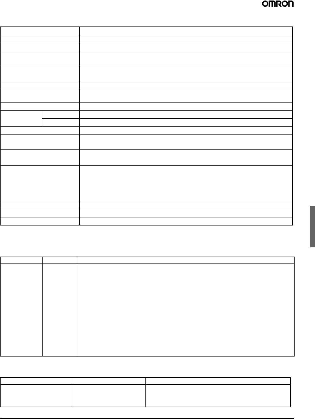
Life expectancy (x10
3
operations)
Switching current (A)
10
30
50
70
100
300
500
700
1,000
3,000
5,000
2
4
6
8
10
12
0
35 VDC
resistive load
14
16
250 VAC
resistive load
0
100
120
140
160
180
200
-25
20
30
40
50
60
70
80
90
100
23
Maximum voltage (%)
Switching temperature (°C)
G5LE-1-E
Max. Switching Capacity Life Expectancy Ambient Temp. Vs. Max. Voltage
Note: The maximum coil voltage refers
to the maximum value in a varying
range of operating power voltage,
not a continuous voltage.
Switching current (A)
Switching voltage (V)
1,000
AC resistive
load (for -E)
0.5
1
5
10
12
14
16
0
10
30
50
125
250
500
8
PCB Relay G5LE 195
Dimensions
Note: 1. All units are in millimeters unless otherwise indicated.
2. Orientation marks are indicated as follows:
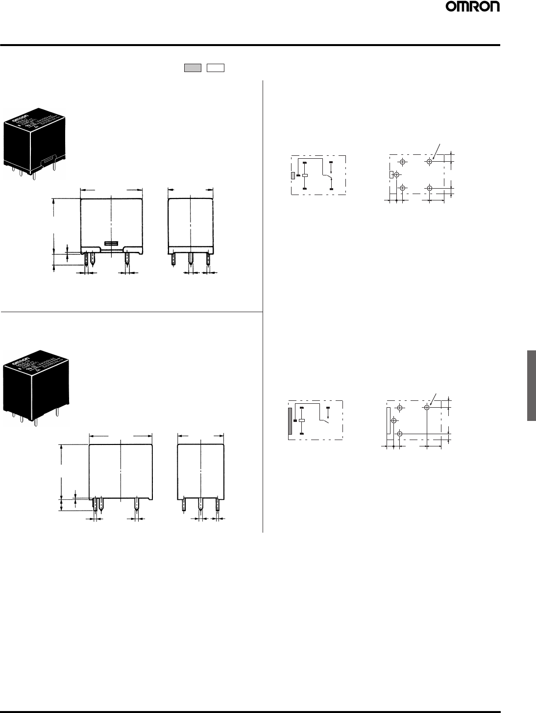
G5LE-14
G5LE-1A4
22.5 max.
(21.6)*
16.5 max.
(15.6)*
19.0 max.
(18.5)*
0.5
3.5
0.2 1 1.2 0.4
Terminal
Arrangement/Internal
Connections (Bottom View)
Mounting Holes
(Bottom View)
SPDT
Tolerance: ±0.1 mm
unless specified
SPDT
12.2
12
2(2.55)
(2.25)
Five, 1.3 dia. holes
+0.2
0
(5.75)
(2.25)
1
2
5
3
4
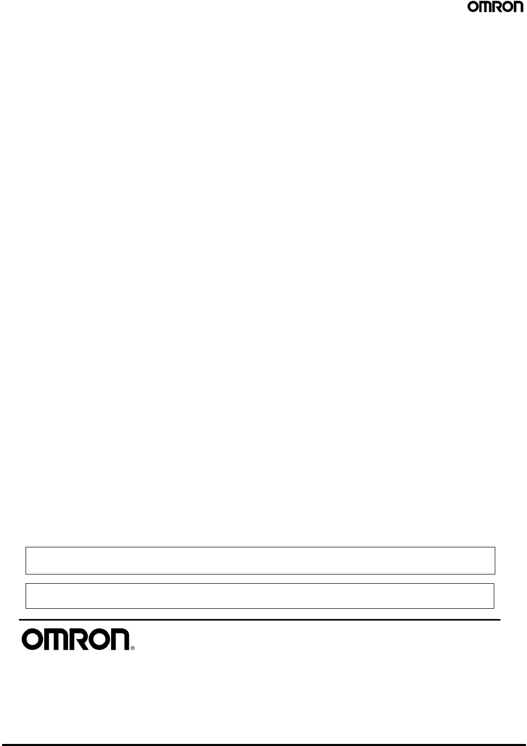
G5LE-1
G5LE-1A
*Average value
22.5 max.
(21.6)*
19.0 max.
(18.5)*
0.5
3.5
0.2 1
16.5 max.
(15.6)*
1.2 0.4
Terminal
Arrangement/Internal
Connections (Bottom View)
Mounting Holes
(Bottom View)
SPST-NO
Tolerance: ±0.1 mm
unless specified
1
2
5
3
*Average value
SPST-NO
12.2
12
2
(2.55)
(2.25)
(5.75)
Four, 1.3 dia. holes
+0.2
0
(2.25)
PCB Relay G5LE
OMRON ON-LINE
Global - http://www.omron.com
USA - http://www.components.omron.com
Cat. No. X301-E-1d Printed in USA
OMRON ELECTRONIC
COMPONENTS LLC
55 E. Commerce Drive, Suite B
Schaumburg, IL 60173
847-882-2288
08/13 Specifications subject to change without notice
All sales are subject to Omron Electronic Components LLC standard terms and conditions of sale, which
can be found at http://www.components.omron.com/components/web/webfiles.nsf/sales_terms.html
ALL DIMENSIONS SHOWN ARE IN MILLIMETERS.
To convert millimeters into inches, multiply by 0.03937. To convert grams into ounces, multiply by 0.03527.
