Corning Optical Communication Wireless 1MXU25 ONE - MXU ADD-ON TDD 2496-2690MHz User Manual
Corning Optical Communication Wireless ONE - MXU ADD-ON TDD 2496-2690MHz
Contents
- 1. User Manual
- 2. User Manual Warning Attestation
User Manual

Mid-Power Remote
Expansion Unit (MxU)
User Manual
Corning Optical Communications User Manual | CMA-xxx-AEN | Page 2
Warranties
Hardware Warranty
Corning Optical Communications LLC (
“
Corning
”
) warrants to
the original purchaser (
“
Customer
”
) that for the duration of
the warranty period, one (1) year, commencing on the date of
shipment of the Hardware, unless otherwise agreed in writing
by Corning (the
“
Hardware Warranty Period
”
), the Hardware
furnished by Corning shall be free in all material respects from
defects in material and workmanship, and shall conform to
the applicable portions of the Specifications, as defined below
(the
“
Hardware Warranty
”
). If notified by Customer of any
such defects in material or workmanship or nonconformity
with applicable portions of the Specifications within the
Hardware Warranty Period, Corning shall promptly, at its own
election and expense, repair or replace any such Hardware
proven to be defective under the terms of this Hardware
Warranty. Such repair or replacement shall be Customer
’
s sole
remedy and Corning
’
s sole obligation in the event this
Hardware Warranty is invoked. If any components comprising
a part of the Hardware are replaced or repaired during the
Hardware Warranty Period, the Hardware Warranty Period for
such repaired or replaced components shall extend to the
longer of (i) the balance of the Hardware Warranty Period or
(ii) three (3) months from the date of repair or replacement.
For purposes of this Warranty,
“
Specifications
”
shall mean the
specifications and performance standards of the Products as
set forth in documents published by Corning and delivered to
Customer which contain technical specifications or
performance standards for the Products.
If Customer invokes this Hardware Warranty, it shall notify
Corning promptly of the claimed defect. Customer will allow
Corning to inspect the Hardware at Customer
’
s location, or to
return the Hardware to Corning
’
s closest repair facility. For
Hardware returned to Corning
’
s repair facility, Customer shall
be responsible for payment of all transportation and freight
costs (including insurance) to Corning
’
s repair facility, and
Corning shall be responsible for all transportation and freight
costs (including insurance) incurred in connection with the
shipment of such Hardware to other repair facilities of
Corning and/or its return to Customer.
Notwithstanding the foregoing, in no event will Corning be
liable for damage to products resulting from improper
handling during or after shipment, misuse, neglect, improper
installation, operation or repair (other than by authorized
Corning personnel), alteration, accident, or for any other cause
not attributable to defects in materials or workmanship on
the part of Corning. Corning shall not reimburse or make any
allowance to Customer for any labor charges incurred by
Customer for replacement or repair of any goods unless such
charges are authorized in advance in writing by Corning.
Software Warranty
Corning Optical Communications LLC (“Corning”) warrants to
the original purchaser (“Customer”) that for the duration of the
warranty period, one (1) year, commencing on the date of
shipment of the Software, unless otherwise agreed in writing by
Corning (the “Software Warranty Period”), the Software shall
conform with, and perform the functions set forth in the
Specifications, and shall be free from defects in material or
workmanship (the “Software Warranty”). In the event the
Software is proven to be defective under the terms of this
Software Warranty, Corning shall correct such defects or failure
and ensure that the Software conforms with, and performs the
functions set forth in, the Specifications. Customer will allow
Corning to inspect the Software at Customer’s location or to
return it to Cornings’ closest repair facility.
Notwithstanding the foregoing, Corning shall have no obligation
under the Software Warranty if the Software is modified or used
with hardware or software not supplied or approved by Corning
or if the Software is subject to abuse, improper installation or
application, accident, electrical or environmental over-stress,
negligence in use, storage, transportation or handling.
Third-party software distributed with the software may carry
certain warranties which, to the maximum extent allowed by
law, Corning hereby assigns, transfers and otherwise conveys to
Customer, provided, however, that Corning itself provides no
warranty of any kind, express, implied, statutory or otherwise,
for any third-party software provided hereunder.
Corning does not warrant any hardware, software or services not
provided by Corning.
THIS WARRANTY IS THE ONLY WARRANTY MADE BY CORNING
AND IS IN LIEU OF ALL OTHER WARRANTIES, EXPRESS OR IMPLIED
INCLUDING, BUT NOT LIMITED TO, THE IMPLIED WARRANTIES OF
MERCHANTABILITY AND FITNESS FOR A PARTICULAR PURPOSE.
CORNING SHALL NOT BE LIABLE FOR ANY OTHER DAMAGE
INCLUDING, BUT NOT LIMITED TO, INDIRECT, SPECIAL OR
CONSEQUENTIAL DAMAGES ARISING OUT OF OR IN
CONNECTION WITH FURNISHING OF GOODS, PARTS AND
SERVICE HEREUNDER, OR THE PERFORMANCE, USE OF, OR
INABILITY TO USE THE GOODS, PARTS AND SERVICE. CORNING
SALES AGENTS OR REPRESENTATIVES ARE NOT AUTHORIZED TO
MAKE COMMITMENTS ON WARRANTY RETURNS.
Corning Optical Communications User Manual | CMA-xxx-AEN | Page 3
Returns
In the event that it is necessary to return any product against
above warranty, the following procedure shall be followed:
1.
Return authorization is to be received from Corning prior
to returning any unit. Advise Corning of the model, Serial
number, and discrepancy. The unit may then be
forwarded to Corning, transportation prepaid. Devices
returned collect or without authorization may not be
accepted.
2.
Prior to repair, Corning will advise the customer of our
test results and any charges for repairing
customer-caused problems or out-of-warranty conditions
etc.
3.
Repaired products are warranted for the balance of the
original warranty period, or at least 90 days from date of
shipment.
Limitations of Liabilities
Corning’s liability on any claim, of any kind, including
negligence for any loss or damage arising from, connected
with, or resulting from the purchase order, contract,
quotation, or from the performance or breach thereof, or from
the design, manufacture, sale, delivery, installation,
inspection, operation or use of any equipment covered by or
furnished under this contact, shall in no case exceed the
purchase price of the device which gives rise to the claim.
Except as expressly provided herein, Corning makes no
warranty, expressed or implied, with respect to any goods,
parts and services provided in connection with this agreement
including, but not limited to, the implied warranties of
merchantability and fitness for a particular purpose. Corning
shall not be liable for any other damage including, but not
limited to, indirect, special or consequential damages arising
out of or in connection with furnishing of goods, parts and
service hereunder, or the performance, use of, or inability to
use the goods, parts and service.
Reporting Defects
The units were inspected before shipment and found to be
free of mechanical and electrical defects. Examine the units
for any damage that may have been caused in transit. If
damage is discovered, file a claim with the freight carrier
immediately. Notify Corning as soon as possible in writing.
Note: Keep all packing material until you have completed the
inspection.
Warnings and Admonishments
There may be situations, particularly for workplace
environments near high-powered RF sources, where
recommended limits for safe exposure of human beings to RF
energy could be exceeded. In such cases, restrictive measures
or actions may be necessary to ensure the safe use of RF energy.
The equipment has been designed and constructed to prevent,
as far as reasonably, practicable danger. Any work activity on or
near equipment involving installation, operation or maintenance
must be, as far as reasonably, free from danger.
Where there is a risk of damage to electrical systems involving
adverse weather, extreme temperatures, wet, corrosive or dirty
conditions, flammable or explosive atmospheres, the system
must be suitably installed to prevent danger.
Equipment provided for the purpose of protecting individuals
from electrical risk must be suitable for the purpose and properly
maintained and used. This covers a range of activities including
lifting, lowering, pushing, pulling, carrying, moving, holding or
restraining an object, animal or person from the equipment. It
also covers activities that require the use of force or effort, such
as pulling a lever, or operating power tools.
Where some of the abovementioned activities are required, the
equipment must be handled with care to avoid being damaged.
Observe standard precautions for handling ESD-sensitive
devices. Assume that all solid-state electronic devices are
ESD-sensitive. Ensure the use of a grounded wrist strap or
equivalent while working with ESD-sensitive devices. Transport,
store, and handle ESD-sensitive devices in static-safe
environments.
Regulatory Compliance
Information
WARNINGS!
•
This is
NOT
a
CONSUMER
device. It is designed for
installation by
FCC LICENCEES
and
QUALIFIED INSTALLERS
.
You
MUST
have an
FCC LICENSE
or express consent of an
FCC Licensee to operate this device. Unauthorized use may
result in significant forfeiture penalties, including penalties in
excess of $100,000 for each continuing violation.
•
ANTENNAS
: Use only authorized and approved antennas,
cables and/or coupling devices! The use of unapproved
antennas, cables or coupling devices could cause damage and
may be of violation of FCC regulations. The use of unapproved
antennas, cables and/or coupling devices is illegal under FCC
regulations and may subject the user to fines.
RF Safety
WARNING!
To comply with FCC RF exposure compliance requirements,
each individual antenna used for this transmitter must be
installed to provide a separation distance greater than 100 cm
or more from all persons during normal operation and must

Corning Optical Communications User Manual | CMA-xxx-AEN | Page 4
not be co-located with any other antenna for meeting RF
exposure requirements.
•
The design of the antenna installation needs to be
implemented in such a way so as to ensure RF radiation
safety levels and non-environmental pollution during
operation.
•
Antenna gain should not exceed 12.5 dBi.
•
Each individual antenna used for this transmitter must be
installed to provide a separation distance greater than 100
cm or more from all persons and must not be co-located
with any other antenna for meeting RF exposure
requirements.
•
The design of the antenna installation needs to be
implemented in such a way so as to ensure RF radiation
safety levels and non-environmental pollution during
operation.
Compliance with RF safety requirements:
•
Corning products have no inherent significant RF radiation.
•
The RF level on the downlink is very low at the downlink
ports. Therefore, there is no dangerous RF radiation when
the antenna is not connected.
Standards and Certifications
Corning products have met the approvals of the following
certifying organizations:
Category Standards
Safety:
IEC 60950-1
UL 60950-1, Second edition,
Information technology equipment
TUV safety certifications
Radio: FCC 47 CFR Part 15, Subpart B
FCC 47 CFR Part 27, Subpart C – TDD
2500 MHz frequency band
FCC Part 2
NEBS OSP Class 2
Licensee Contact Information
Industrial boosters may only be used by FCC licensees or those
given express (individualized) consent of license. Corning Optical
Communications certifies all of the VARs listed as licensed
installers for Corning. For the list of licensed VARs, please contact
the Tech Support Hotline: (U.S.) 410-553-2086 or 800-787-1266
About This Manual
This user manual describes how to perform the physical
installation of the mid-power remote expansion unit (MxU). The
installation procedures of other units (e.g., HEU/IHU, OIU, and
MRU) relevant to the system are detailed in their user manuals
(see Additional Relevant Documentation).
Additional Relevant Documents
The following documents are required if the corresponding units
are included in your system.
Document Name
Corning® Optical Network Evolution (ONE™) Solutions
System Installation User Manual (includes HEU/IHU
information)
Mid-Power Remote Unit User Manual
Corning® Optical Network Evolution (ONE™) Solution
Software and Management GUI v3.2

Corning Optical Communications User Manual | CMA-xxx-AEN | Page 5
TABLE OF CONTENTS
1 Introduction
1.1 Key Features and Capabilities ................................................... 6
1.2 System Description ....................................................................... 7
1.3 System Monitoring and Management .................................. 8
1.4 MxU Interfaces ............................................................................... 9
2 Installation Guidelines
2.1 Installation Requirements ......................................................... 11
2.2 Installation Location .................................................................... 11
2.3 Environmental ............................................................................... 11
2.4 Powering .......................................................................................... 11
2.5 Grounding Requirement ............................................................ 11
2.6 Cable Routing ................................................................................. 11
2.7 Manual Handling .......................................................................... 11
3 System Installation
3.1 Unpacking and Inspection ........................................................ 12
3.2 Additional Required Items........................................................ 12
3.3 Installing MxU in 19-in Rack .................................................... 13
3.4 MxU Connections ........................................................................ 13
3.4.1 Grounding Connections................................................. 13
3.4.2 RF and Coax Connections to MRU ............................. 13
3.4.3 Management Connections ........................................... 14
3.4.4 Power Connections.......................................................... 14
3.4.4.1 AC Power Connections ............................... 14
3.4.4.2 DC Models ....................................................... 15
3.5 Verifying Normal Operation .................................................... 16
4
Appendices
4.1 Appendix A: System Specifications ........................................ 17
4.2 Appendix B: Ordering Information ...................................... 20
Corning Optical Communications User Manual | CMA-586-AEN | Page 6
1
1
INTRODUCTION
The mid-power remote expansion unit (MxU) is a new addition
to the Corning® optical network evolution (ONE™) solution
mid-power product line which enables medium power
transmission for the 2.5 GHz band (TDD). The MxU is a 1U
add-on unit that enhances the scalable multiservice MRU
solution, adding additional service support at a relatively low
cost.
The MxU expands the MRUs service distribution at remote
locations to include the 2.5 GHz LTE (TDD) band, enabling up to
eight operator services (with the MRU) to be distributed over a
single broadband infrastructure.
The MxU interfaces to the MRU, providing broadband
frequency support over UL/DL RF expansion ports. It supports
the 2.5 GHz frequency band in a single enclosure and includes a
future option for connecting additional add-on units for even
more band support.
All eight services are distributed over the same infrastructure:
routed to the MRU over a single optic fiber, distributed over the
same footprint and managed as a single element via a web
session to the headend control module (HCM) — as the MRU.
MxU | Figure 1.1
1.1 Key Features and Capabilities
Supported service
Supports the 2.5 GHz LTE (TDD) band
Supported channels
Supports three contiguous 20 MHz channels
Expands mid-power remote unit (MRU) services
Expands MRU support to eight services per coverage area over
the same footprint
Support for future bands via extension port interfaces to
additional add-on unit
Optical fiber savings
All eight services are routed over a single optic fiber pair
Design and deployment flexibility
MxU available in AC or DC power supply options
Antenna splitting schemes are possible due to the higher
power output capability
Scalable design
Scalable design enables future support of additional band via
connection to additional expansion unit without disruption to
existing services
Simple installation and maintenance
All connections and status LEDs located on front panel
Rack and wall-mountable installation
Field upgrdeable
Management and control
MxU management and control are supported by Corning®
optical network evolution (ONE™) solution software v3.2 and
higher
Management and control via the MRU
Corning Optical Communications User Manual | CMA-xxx-AEN | Page 7
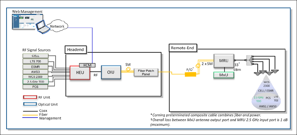
1.2 System Description
In the downlink, at the headend, BTS/BDA RF signals are
conditioned by service-specific RIMs installed in the headend unit
(i.e., HEU/IHU), ensuring a constant RF level. All eight conditioned
signals (MRU + MxU) are then forwarded to the optical interface
unit (OIU) and converted by the OIMs to an optical signal for
transporting over single-mode fiber to the MRU at the remote
location.
The services supported by the MRU are filtered and amplified
by the MRU, whereas the 2.5 GHz band is filtered and amplified
by the MxU. All eight services are combined and distributed via
the MRU antenna port over the broadband antenna
infrastructure installed at the remote locations. In the uplink,
the process is reversed.
MxU System Block Diagram | Figure 1.2
Corning Optical Communications User Manual | CMA-xxx-AEN | Page 8
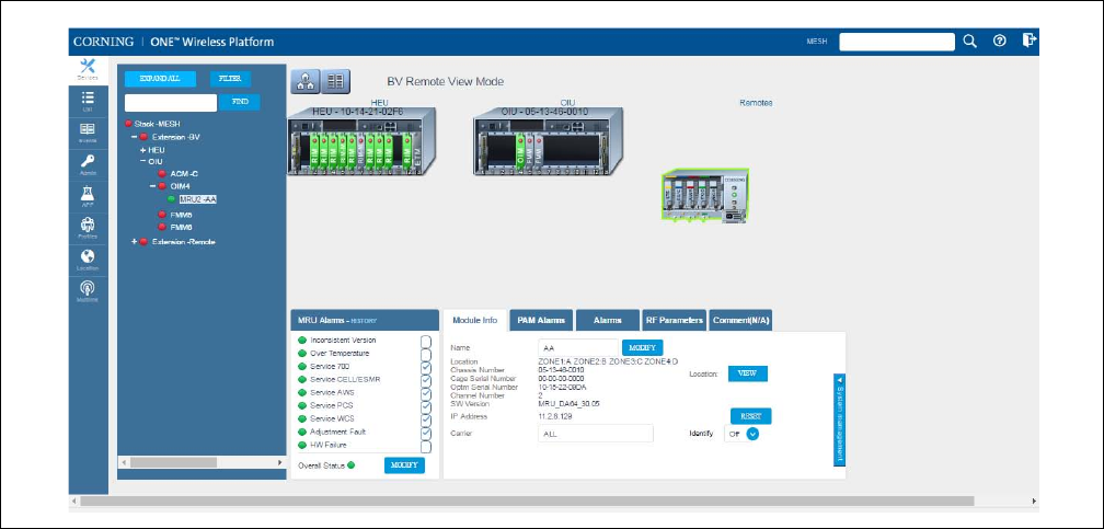
1.3 System Monitoring and
Management
The Corning Optical Network Evolution (ONE
™
) Solution
headend control module (HCM) enables centralized,
system-level element management and
provides
c
omprehensive end-to-end, single source setup and
management of the active RF system components after their
physical installation. Management capabilities are provided for
the MxU via the host MRU.
Note: Refer to the Corning ONE™ HCM and management GUI user
manual for a complete description of the web management
application.
Example of MxU Device View Tab | Figure 1.3
Corning Optical Communications User Manual | CMA-xxx-AEN | Page 9
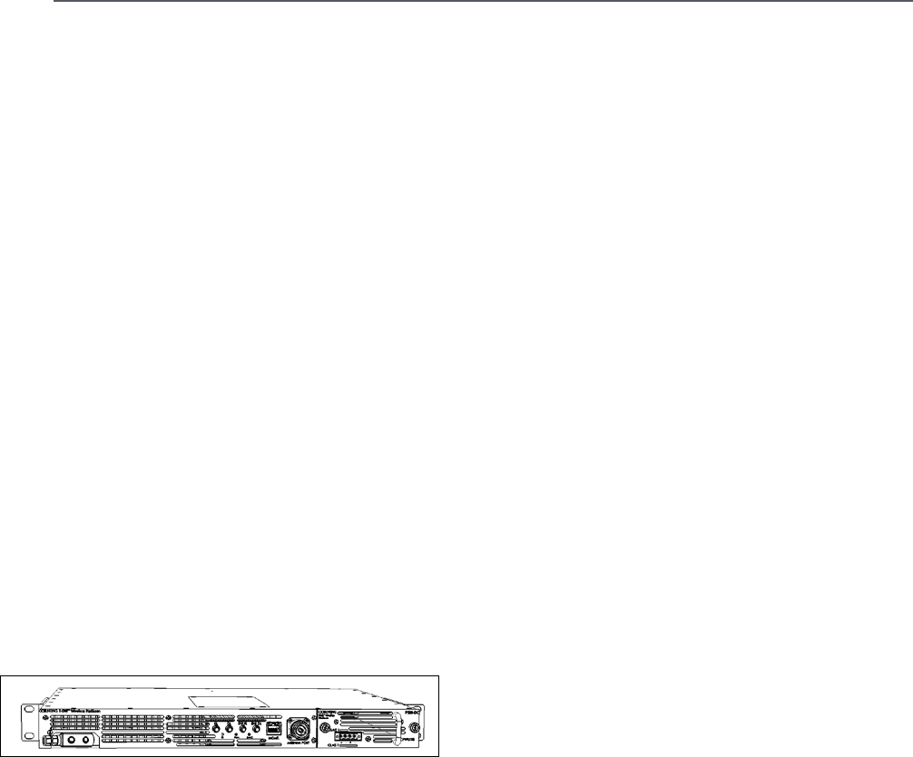
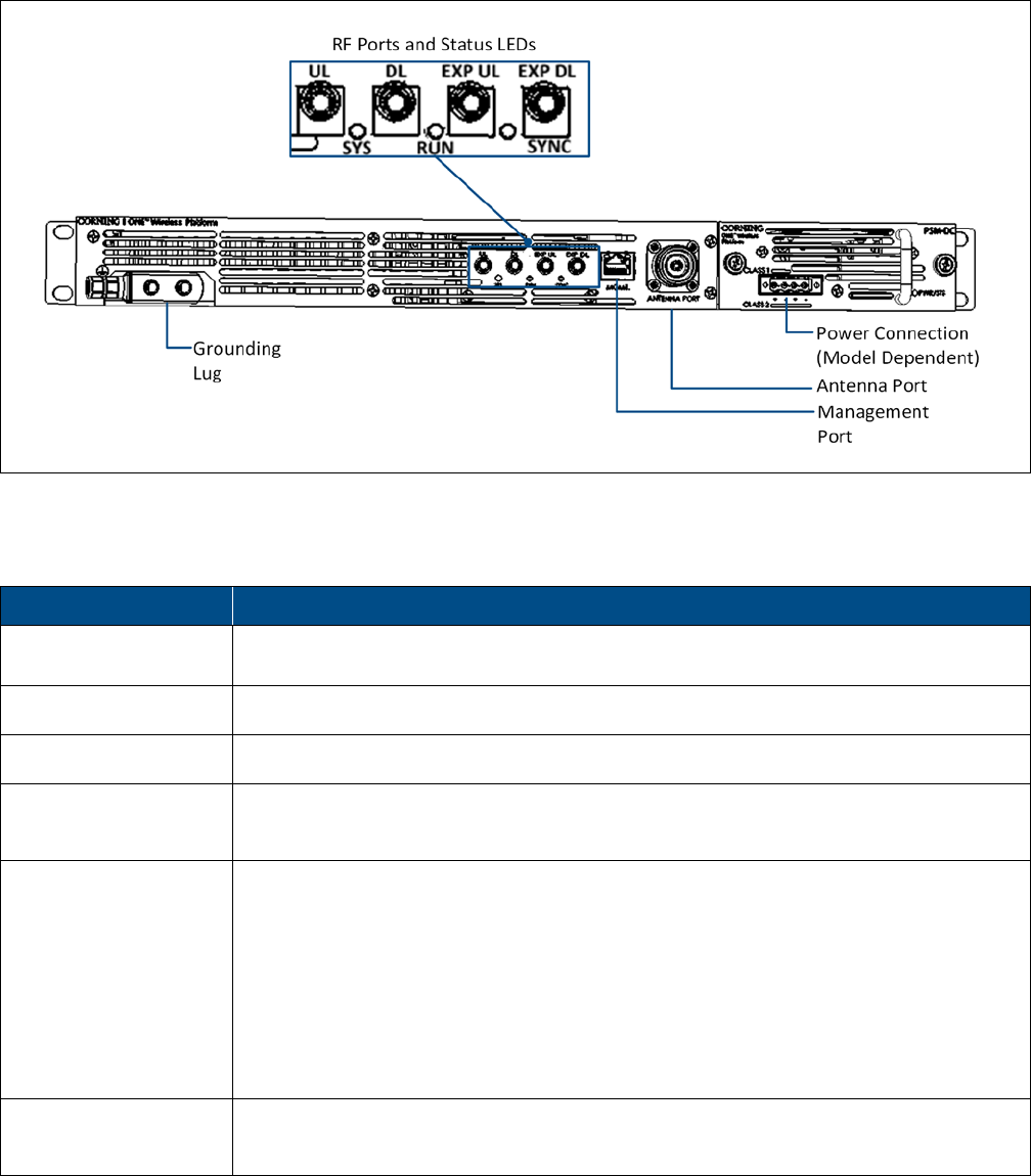
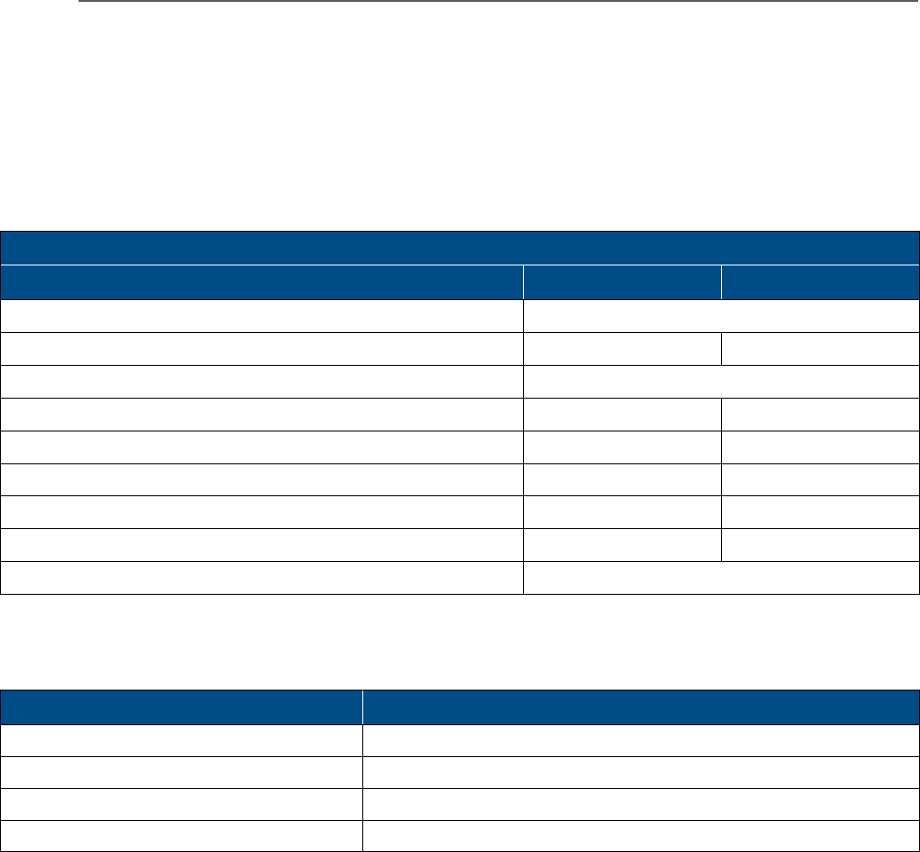
1.4 MxU Interfaces
The MxU consists of the MxU enclosure and power supply
module (AC / DC). All of the MxU interfaces are located on the
units’ front panel. The unit interfaces include the RF, power
(PSM), and management connections as well as status LEDs.
MxU Interface Ports | Figure 1.4
Table 1.1 and Table 1.2 provide descriptions of the MxU interfaces and LEDs.
Port Description
UL / DL QMA RF output connectors — used for MRU expansion connections
Exp. UL / Exp. DL Future option (N / A)
MGMT RJ45 local management port — used for MxU-to-MRU management connection
Antenna port 4.3-10 DIN male type duplexed RF antenna port — used for connecting to MRUs 2.5 GHz
input port
Power connector AC or DC power input connector (depending on PSM model):
AC - three-pin AC connector compatible with provided AC power cable; 100-240 VAC
DC connector – four-pin terminal block connector supporting 12-16 AWG for both Class1 and
Class2 power connections; DC Class1 power input — 48 VDC (40-60 VDC); DC Class2 power
input — 30-60 VDC
Note: See Appendix A for complete power specifications.
Grounding lug Two-hole, standard barrel grounding lug; for use with stranded copper wire conductors;
10-14 AWG; holes - 1/4 inch
MxU Interface Descriptions | Table 1.1

Corning Optical Communications User Manual | CMA-xxx-AEN | Page 10
LED Description
PWR / STS
(PSM-AC / PSM-DC)
Steady green — power supply module power input OK
Red — faulty power input
RUN Blinking green — module software is running and operational
Rapid blinking green — “Identify” feature has been enabled via the management GUI
Off — No power input detected
SYNC Steady green — TDD sync locked
Steady red — TDD signal out of sync
STS Steady green — normal operation; overall status OK
Steady red — indicates generated alarm in unit
Blinking red — “Over temperature” alarm active; Indicates temperature has exceeded
threshold (with door open)
Note: Temperature alarm is set as first priority and overrides any other alarm indication.
MGMT RJ45 Port LEDs Blinking green — Ethernet connection to MRU OK
MxU LED Description | Table 1.2

Corning Optical Communications User Manual | CMA-xxx-AEN | Page 11
2
2
INSTALLATION GUIDELINES
This chapter provides the general guidelines for installing the
MxU and includes information such as site considerations and
installation requirements.
2.1 Installation Requirements
•
Working space available for installation and maintenance for
each mounting arrangement. Ensure unrestricted airflow.
•
Ensure grounding connector is within reach of the ground
wire.
•
Ensure a power source is within reach of the power cord and
the power source has sufficient capacity.
•
Where appropriate, ensure unused RF connectors are
terminated.
•
Reduce signal loss in feeder cable by minimizing the length
and number of RF connections.
•
Ensure the equipment will be operated within the stated
environment (refer to datasheet).
•
Where appropriate, confirm availability of suitably
terminated grade of RF and optical fiber.
•
Observe handling of all cables to prevent damage.
2.2 Installation Location
•
Mounting surface shall be capable of supporting the weight
of the equipment.
•
In order to avoid electromagnetic interference, a proper
mounting location must be selected to minimize interference
from electromagnetic sources such as large electrical
equipment
•
Do not locate the equipment near large transformers or
motors that may cause electromagnetic interference.
2.3
2.4 Environmental
Humidity has an adverse effect on the reliability of the
equipment. It is recommended to install the equipment in
locations having stable temperature and unrestricted airflow.
The installation location for the system should be well
ventilated. The equipment has been designed to operate at the
temperature range and humidity level as stated in the product
specifications at temperatures ranging from -40~65 degrees
Celsius and a relative humidity of maximum 85 percent.
2.5 Powering
The power supply unit provides power to all modules within
the equipment. Depending on the product variant, it is
recommended that the PSU operates on a dedicated AC circuit
breaker or fused circuit.
ATTENTION!
The MxU is intended for connection to a TN power
system and IT power system of Norway only.
2.6 Grounding Requirement
Verify that the equipment has been well grounded. This
includes MxU, MRU, antennas, and all cables connected to the
system. Ensure lightning protection for the antennas is
properly grounded.
2.7 Cable Routing
Ensure all cables, e.g., power cable, feeder cable,
commissioning cable, connecting are properly routed (use drip
loops) and secured so that they are not damaged.
2.8 Manual Handling
During transportation and installation, take necessary
handling precautions to avoid potential physical injury to the
installation personnel and the equipment.

Corning Optical Communications User Manual | CMA-xxx-AEN | Page 12
3
3
SYSTEM INSTALLATION
This chapter describes the installation procedure for the MxU
add-on unit. THE MxU supports the 2.5 GHz TDD band and is
installed in conjunction with the mid-power remote unit
(MRU) (ordered and installed separately), expanding the
number of supported services to eight.
3.1 Unpacking and Inspection
Unpack and inspect the cartons as follows:
Item Description Quantity
Mid-power Expansion Unit:
MRU-ASM-AO-AC
MRU-ASM-AO-DC
1
Rack-Mount Brackets (factory
assembled)
2
QMA/QMA RF cables — used for UL/DL
RF connections
2
RJ45 100 Base-T Ethernet Cable
(P/N: 705A055702) — used for
management port connection
1
4.3-10 DIN RF Jumper Cable (P/N:
705A055602) — used for antenna port
connection
1
AC Power Cable (for MxU AC models
only) - straight, U.S 10 A ,UL, L=8-2.5 m
,black,110 V (P/N 705900007)
1
MxU Package Items | Table 3.1
1. Open the shipping carton and carefully unpack each unit
from the
prote
ctive
packing material.
2. Please verify that the items listed in Table 3.1 are included
in your package and check for signs of external damage. If
there is any damage, call your Corning service
representative.
3.2 Additional Required Items
The following additional items / tools are required (not provided)
for installing the MxU:
1. Four rack-mount nuts and screws for securing unit in
communication rack (type depends on rack.
2. Torque wrench for RF connectors (i.e., QMA, 4.3-10 DIN).
3. Grounding tools and components:
•
Grounding wire - grounding wire should be sized
according to local and national installation
requirements. The provided grounding lug supports
14 AWG to 10 AWG stranded copper (or 12 AWG to 10
AWG solid) wire conductors.
Note: The length of the grounding wire depends on the proximity
of the switch to proper grounding facilities.
•
Phillips-head screwdriver
•
Crimping tool to crimp the grounding wire to the
grounding lug
•
Wire-stripping tool to remove the insulation from the
grounding wire
Corning Optical Communications User Manual | CMA-xxx-AEN | Page 13
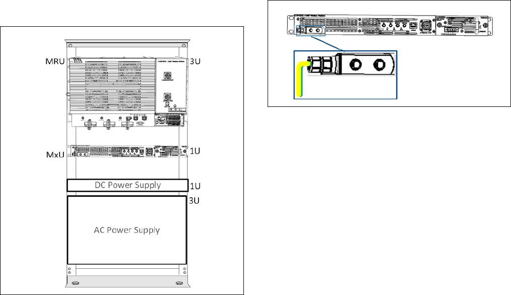
3.3 Installing MxU in 19-in Rack
Note: MxU requires 1U rack height availability.
1. Determine the location of the MxU in the rack while
considering additional units (e.g., MxU, power supply).
Refer to Figure 3.1.
Example of Rack Installation | Figure 3.1
2. Install the unit in the rack and secure to rack frame via
applicable bracket holes using appropriate rack nuts and
screws.
3.4 MxU Connections
3.4.1 Grounding Connections
WARNING!
This unit must always be grounded. Consult an
appropriate electrical inspection authority or an electrician if
you are uncertain that suitable grounding is available.
DO NOT
CONNECT POWER BEFORE GROUNDING!
Note: An internationally acceptable color code of the ground
connection wire is green/yellow.
To ground the MxU
The grounding connection is performed via a two-hole,
standard barrel grounding lug located on the left of the front
panel (see Figure 3.2).
Prise de terre du châssis MxU
La mise à la terre est réalisée en utilisant une cosse deux trous
a œillet standard, située à gauche de la face avant (voir Figure
3.2).
MxU Grounding Connection | Figure 3.2
1. Use a wire-stripping tool to remove approximately 0.4 inch
(10.9 mm) of the covering from the end of the grounding
wire.
2. Insert the stripped end of the grounding wire into the open
end of the grounding lug.
3. Crimp the grounding wire in the barrel of the grounding
lug. Verify that the ground wire is securely attached to the
ground lug by holding the ground lug and gently pulling on
the ground wire.
4. Prepare the other end of the grounding wire and connect it
to an appropriate grounding point at the site to ensure
adequate earth ground.
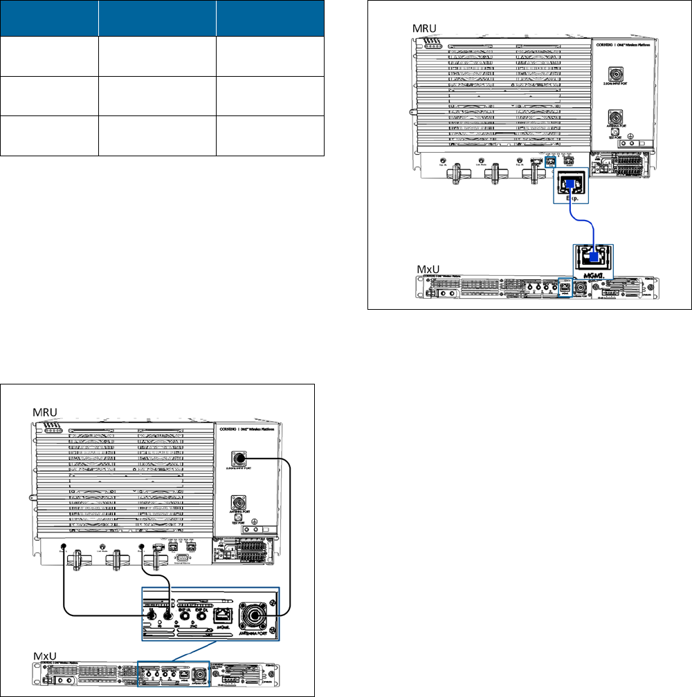
3.4.2 RF and Coax Connections to MRU
Refer to Figure 3.3 and connect the RF cables according to the
Table 3.2.
Note: The MRU connections are detailed in the quick installation
sheet provided with the MRU (CMA-398-AEN) and in the user
manual (CMA-438-AEN) which can also be downloaded from the
Corning portal.
Corning Optical Communications User Manual | CMA-xxx-AEN | Page 14
Connect MxU
Port…
To MRU Port… Using the
Provided…
“UL” “Exp. UL” QMA/QMA RF
cable
“DL” “Exp. DL” QMA/QMA RF
cable
“Antenna
Port”
“2.5 GHz Input
Port”
4.3-10 DIN RF
Cable
MxU-to-MRU Connections | Table 3.2
IMPORTANT!
•
Keep the cable straight or adhere to the bend radius of the
cable when tightening the nuts:
•
Minimum bend radius (one time): 8 mm
•
Minimum bend radius (repetition): 40 mm
•
Screw torque > = 5 Nm
•
Make sure that the cable is not stressed when tightened
Example of MxU-to MRU Connections | Figure 3.3
3.4.3 Management Connections
Referring to Figure 3.4, connect the MxU “MGMT” port to the
MRU RJ45 “Exp” Port using and RJ45 Ethernet cable.
Example of MxU-to MRU Connections | Figure 3.4
3.4.4 Power Connections
CAUTION!
Any open RF port on the MxU or improper connection
between units, can damage internal power amplifier after the
equipment is powered on. Make sure all connections are
performed correctly before powering.
Note the following:
•
The MxU power supply module (PSM) is located on the right
side of the front panel.
•
The PSM is model dependent: PSM-AC / PSM-DC
3.4.4.1 AC Power Connections
ATTENTION!
1. Approved power cable
–
the
entire length of the power
cable (or flexible cord) and the insulation must be intact.
The cable must be firmly connected to both the electrical
plug and the unit itself.
2. Standard plug
–
the use of a standard plug is mandatory.
The use of a non-standard power plug can cause
electrocution! Also, plugging a non-standard plug into a
standard socket that does not correspond to the plugs’
shape, can damage the socket making it a safety hazard.
Connect the MxU power connector to the AC power source
using the provided AC power cable (P/N 705900007):
•
Power input: 100-240 VAC/50-60 Hz
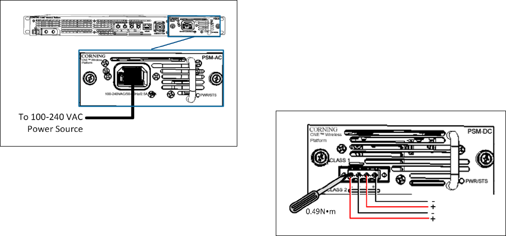
Corning Optical Communications User Manual | CMA-xxx-AEN | Page 15
•
Power consumption: 128 W (maximum)
•
Maximum AC current consumption: 2.5 A
See Figure 3.5 for AC connector location.
MxU PSM-AC Connection | Figure 3.5
Modèles Électriques AC
ATTENTION!
1. Câble d'alimentation qui est approuvé
-
la totalité de la
longueur du câble d'alimentation (ou cordon souple ) et de
l'isolation doit être intact. Le câble doit être bien connecté
à la fois à la prise électrique et l'appareil.
2. Prise électrique standard
–
l'utilisation d'une fiche
standard est obligatoire. L'utilisation d'un cordon
d'alimentation non standard peut entraîner
l'électrocution!
De meme, brancher une fiche non-standard sur une prise
standard ne correspondant pas à la forme de de la fiche, peut
endommager la Prise, ce qui en fait un danger de sécurité.
Branchez la prise d'alimentation du MxU à la source
d'alimentation secteur à l'aide du câble d'alimentation secteur
fourni:
•
Alimentation: 100-240 VAC / 50-60 Hz
•
Consommation d'énergie : 128 W (maximum)
•
La consommation de courant maximale: 2.5 A
Voir Figure 3 pour l'emplacement du connecteur AC
3.4.4.2 DC Models
DC models include one four pin terminal block connector
which supports both NEC CLASS1 and CLASS2 :
•
CLASS2 (default) – supported by the four pins of the DC
terminal block connector for remote feed supporting two DC
wiring pairs (see Figure 3.6)
•
CLASS1 - supported by the first two pins (LT-to-RT) of the DC
terminal block for local plant feed. To use CLASS1 - user must
change default connector mode from CLASS2 to CLASS1 (see
“Local plant feed – CLASS1 connector” description).
Example of DC CLASS2 Wiring | Figure 3.6
Remote feed – CLASS2 connector (default)
DC CLASS2 connector specs:
Supported wire AWG:
•
Conductor cross-section, solid (AWG/mm²): 30~12 /
0.2~2.5
•
Conductor cross-section, flexible (AWG/ mm²): 30~12 /
0.2~2.5
•
Wire strip length: 9~10 mm
DC Power input: 24 VDC / 48 VDC (20-60 VDC)
Power amplifier consumption per pair:
•
First pair: 50 W
•
Second pair: 78 W
Maximum power consumption
:
131 W
Maximum current consumption:
•
First pair: 2.1 A
•
Second pair: 3.3 A
Maximum current draw per pair: 64 W
Corning Optical Communications User Manual | CMA-xxx-AEN | Page 16
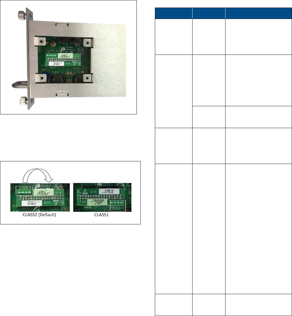
To connect local plant feed — CLASS1 connector:
1. Open PSM captive screws and pull out module from
chassis.
2. Remove the four screws on the top panel to access the
CLASS1/CLASS2 connector. See Figure 3.7.
PSM-DC Top Panel Removed | Figure 3.7
3. Disconnect DC input source type connector and re-connect
with the arrows pointing to the “CLASS1” setting. See
Figure 3.8.
Modifying DC Source Input Setting to CLASS1 | Figure
3.8
4. Close top panel and insert PSM-DC in chassis slot.
5. Route DC pair from the first two DC CLASS1 connector pins
to the local power source.
Power input: 48 VDC (40-60 VDC) 9 A maximum
3.5 Verifying Normal Operation
Upon powering up the MxU:
•
Confirm the fans are working after powering.
•
Refer to status LEDs on front panel to confirm normal system
operation according to Table 3.3.
LED Status Description
PWR / STS
(PSM-AC /
PSM-DC)
Steady
green
Power supply module
power input OK
Red Faulty power input
RUN Blinking
green (1
sec.):
“Identify” feature has
been enabled via the
management GUI
Rapid
blinking
System initialized
Off No power input
detected
SYNC Steady
green
TDD sync locked
Steady red TDD signal out of sync
STS Steady
green:
Normal operation;
Overall status OK
Steady red Indicates generated
alarm in unit
Blinking
red
“Over temperature”
alarm active; Indicates
temperature has
exceeded threshold
(with door open)
Note: Temperature
alarm is set as first
priority and overrides
any other alarm
indication.
MGMT RJ45
Port LEDs
Steady
red:
Fault
MxU Status LED Description | Table 3.3
Corning Optical Communications User Manual | CMA-xxx-AEN | Page 17
4
4
APPENDICES
4.1 Appendix A: System Specifications
System Level RF Parameters per 2.5 GHz Service
LTE 2500 MHz (TDD)
RF Parameters DL UL
Frequency Range (MHz) 2496-2690
Maximum Output Power (dBm) 33
Maximum Loss between MxU and MRU (dB) 1.0
Input Power (dBm) -11 to 37
UL Gain Range (dB) -19 to 15
SFDR (dB) 60*
Maximum Intermod Distortion (dBm) ≤ -13
UL NF (dB) (Typical) 12
Gain Flatness/Ripple (dB)
§
+/- 2.0
*For 5 MHz bandwidth
Environmental Specifications
Parameter Value
Operating Temperature -40 to +65°C (-40 to +149°F)
Storage Temperature -30
°
to 85
°
C (-22
°
to 185
°
F)
Humidity 5 percent to 85 percent RH
MTBF 15 years

Corning Optical Communications User Manual | CMA-xxx-AEN | Page 18
DRAFT
Standards and Approvals
Parameter Value
EMC / Radio FCC 47 CFR Part 15, Subpart B
FCC 47 CFR Part 27, Subpart C – TDD 2500 MHz frequency band
FCC Part 2
Safety IEC 60950-1
UL 60950-1, Second edition, Information technology equipment
TUV safety certifications
NEBS OSP Class 2
Physical Specifications
Parameter Value
Ports One 4.3-10 DIN male type duplexed RF antenna port
One UL QMA output connector
One DL QMA output connector
One RJ45 MGMT (local) connection – used for MxU-to-MRU
management connection
One two-hole, standard barrel grounding lug; for use with stranded
copper wire conductors; 10-14 AWG; holes - 1/4 inch
DC IN connectors (for models with PSM-DC) — four pin terminal block
connector supporting 12-16 AWG for both Class1 and Class2 power
connections
One QMA input connector for EXP UL (future option)
One QMA output connector for EXP DL (future option)
Power AC: Power input: 100-240 VAC / 50-60 Hz
Maximum power
consumption:
128 W
Maximum AC
current
consumption:
2.5 A
DC: Power input: DC class 1: 48 VDC (40-60 VDC) 9 A
maximum
DC class 2: 30-60 VD)
Power consumption:
•
First pair: 50 W
•
Second pair: 78 W
Maximum power consumption: 131 W
Maximum current consumption:
•
First pair: 2.1 A
•
Sec
ond pair: 3.3 A

Corning Optical Communications User Manual | CMA-xxx-AEN | Page 19
DRAFT
Parameter Value
Physical Characteristics Mounting: 19-in rack (1U rack height)
Wall-mountable (separately ordered
accessory kit)
Dimensions: 1.75 x 19 x 17.7 in (44.4 x 482.6 x 449.5 mm)
Cooling Feature Active heat dissipation (fan)

Corning Optical Communications User Manual | CMA-xxx-AEN | Page 20
DRAFT
4.2 Appendix B: Ordering Information
Note: The information listed below is updated up to the publishing date. Refer to the MxU datasheet for the most updated ordering
information
MxU Assembly Configurations
Part Number Description
MRU-ASM-AO-AC MRU Add-On Assembly with AC power supply module supporting the 2.5
GHz (TDD) band
MRU-ASM-AO-DC MRU Add-On Assembly with DC power supply module supporting the 2.5
GHz (TDD) band
Extended Radio Interface Modules (RIMe)
Part Number Description
RIMe-25T Extended Radio Interface Module supporting the 2.5 GHz (TDD) band; RF
input — -11 to 37 dBm
Accessories
Part Number Description
BR-MxU_W Mid-Power Expansion Unit Wall-Mountable Bracket

DRAFT
Notes
Corning Optical Communications LLC
•
PO Box 489
•
Hickory, NC 28603-0489 USA
800-743-2675
•
FAX: 828-325-5060
•
International: +1-828-901-5000
•
www.corning.com/opcomm
Corning Optical Communications reserves the right to improve, enhance, and modify the features and specifications of Corning Optical
Communications products without prior notification. A complete listing of the trademarks of Corning Optical Communications is available at
www.corning.com/opcomm/trademarks. All other trademarks are the properties of their respective owners. Corning Optical Communications
is ISO 9001 certified. © 2017 Corning Optical Communications. All rights reserved.
P/N 709C01xxx Rev A00