Criticare Systems orporated CSI8600 Telemetry Device User Manual Manual
Criticare Systems, Incorporated Telemetry Device Manual
Contents
Manual
Page i
VerisTM 8600
Vital Signs Monitor
Operation Manual
3010796 Revision 0
Date 10/04
PRELIMINARY

Page ii
VerisTM 8600
Operation Manual
Copyright 2004, MEDRAD Inc. All rights reserved.
Reproduction of this manual is strictly prohibited
without express written consent of MEDRAD, Inc.
For more information about MEDRAD products
and services, please visit www.medrad.com

Page iii
Contents
Contents................................................................................................................iii
In Case of Emergency Contact .............................................................................xi
MEDRAD Subsidiaries.....................................................................................xi
International Offices.........................................................................................xi
Symbols .............................................................................................................. xiii
Regulatory Symbols....................................................................................... xiii
Safety Symbols.............................................................................................. xiii
System Symbols............................................................................................xiv
Port Symbols .................................................................................................xiv
Miscellaneous Symbols................................................................................. xiv
Safety...................................................................................................................xv
Definitions.......................................................................................................xv
Warnings.........................................................................................................xv
Cautions........................................................................................................ xvii
Introduction .........................................................................................................xxi
Description.....................................................................................................xxi
Intended Use ................................................................................................. xxi
Clinical Use................................................................................................... xxii
Section 1 - Panel Features
Front Panel ................................................................................................................... 1-1
Menu Knob......................................................................................................... 1-2
Color Display...................................................................................................... 1-2
Water Trap and Gas Sampling Connection ....................................................... 1-2
Left Side Panel (Main Monitor) ..................................................................................... 1-3
Communication Port (Main Monitor) ............................................................................. 1-4
Main Monitor Base Connections................................................................................... 1-5
Chassis Ground ................................................................................................. 1-5
DC Connection................................................................................................... 1-5
Exhaust Port....................................................................................................... 1-5
Air Intake Port .................................................................................................... 1-5
Remote Display.................................................................................................. 1-6
Printer ........................................................................................................................... 1-8
Accessory Tray............................................................................................................. 1-8
Veris 8600 Configurations............................................................................................. 1-9
Section 2 - Monitor Setup
Battery Power ............................................................................................................... 2-1
Charging the Battery.......................................................................................... 2-1
Battery Indicators ............................................................................................... 2-2
System Start and Auto-calibration ................................................................................ 2-3
Sensor and Probe Messages............................................................................. 2-4
Gas Calibration .................................................................................................. 2-4
Screen Display and Interface........................................................................................ 2-5
Waveform Slots.................................................................................................. 2-6
Numerical Parameter Boxes .............................................................................. 2-9
Main Menu ....................................................................................................... 2-11
Alarm and Message Areas............................................................................... 2-12
System Status Box........................................................................................... 2-12
Patient Information and Clock.......................................................................... 2-12
Keypad........................................................................................................................ 2-13
Softkey Functions (Main Menu) .................................................................................. 2-14
Changing Settings............................................................................................ 2-14
Saved Setting Profiles...................................................................................... 2-15

Page iv
MEDRAD
Veris
8600
ALARMS Softkey.........................................................................................................2-16
Primary ALARMS Window................................................................................2-17
Invasive Blood Pressure Alarm Settings ..........................................................2-18
Agent Gas Alarms ............................................................................................2-19
PARAMS Softkey (Physiological Parameters)............................................................2-21
Primary PARAMS Window ...............................................................................2-21
SpO2, Respiration, Temperature Menu............................................................2-24
Gas Settings.....................................................................................................2-25
DISPLAY Softkey ........................................................................................................2-27
Waveform Description......................................................................................2-27
Double Height Slots..........................................................................................2-28
Cascaded Slots ................................................................................................2-29
Gain and Sweep...............................................................................................2-30
ADM/DIS Softkey (Admit/Discharge)...........................................................................2-31
Admitting and Discharging Patients..................................................................2-31
Adult/Pediatric/Neonatal (Patient Size) ............................................................2-32
Patient Information ...........................................................................................2-32
Procedure for Admitting a Patient.....................................................................2-32
Procedure for Discharging a Patient.................................................................2-33
CONFIG Softkey (System Configuration)....................................................................2-34
Password Protection.........................................................................................2-35
Date Format......................................................................................................2-35
Time/Date Setting.............................................................................................2-35
Freeze Timeout ................................................................................................2-35
Standby Timeout ..............................................................................................2-35
Standby Tone ...................................................................................................2-35
Alarm Tone Warning.........................................................................................2-35
Print Device ......................................................................................................2-35
Language Settings............................................................................................2-36
PRINT Softkey.............................................................................................................2-37
Default Settings...........................................................................................................2-38
Factory Defaults ...............................................................................................2-38
Section 3 - Alarms and Messages
Alarm Description..........................................................................................................3-1
Remote Display Alarms......................................................................................3-1
Audible Alarms ...................................................................................................3-1
Visible Alarms.....................................................................................................3-2
Waveforms Frozen .............................................................................................3-2
Alert Icons...........................................................................................................3-3
Special Alarm Conditions ..............................................................................................3-3
Alarms at Start Up ..............................................................................................3-3
Alarm Silence .....................................................................................................3-3
Alarms tone warning (Warning Tone).................................................................3-4
Alarm Volume.....................................................................................................3-4
Minimum Volume Auto-Reset.............................................................................3-4
Standby Mode ....................................................................................................3-5
Agent Standby Mode..........................................................................................3-5
Standby Mode Timeout ......................................................................................3-5
SpO2 Low Limit Auto-Reset................................................................................3-5
SpO2 Low Limit Off Alarm ..................................................................................3-5
Triggering an Alarm.......................................................................................................3-6
Alarms Testing ..............................................................................................................3-6

Page v
Contents
Alarm Message List ...................................................................................................... 3-7
Shared Source Alarms....................................................................................... 3-7
ECG Alarms ....................................................................................................... 3-7
SpO2 Alarms ...................................................................................................... 3-7
Temperature Alarms .......................................................................................... 3-8
NIBP Alarms....................................................................................................... 3-9
IBP Alarms ....................................................................................................... 3-10
Capnometry (CO2) Alarms and Messages....................................................... 3-11
Agent Gas Alarms and Messages.................................................................... 3-11
Oxygen Monitoring (O2) Alarms....................................................................... 3-13
System Alerts.............................................................................................................. 3-14
Section 4 - Trends
Description.................................................................................................................... 4-1
Trend Interval..................................................................................................... 4-1
Capacity ............................................................................................................. 4-1
Trend Screen Update......................................................................................... 4-1
Trend Setup .................................................................................................................. 4-2
Graphical Trends .......................................................................................................... 4-4
Scrolling the Graph ............................................................................................ 4-4
Interruption Due to Power Cycling or Standby Mode ......................................... 4-4
Graphical Trend Display..................................................................................... 4-5
Tabular Trends.............................................................................................................. 4-6
Tabular Trend Markers....................................................................................... 4-6
Trend Messages ................................................................................................ 4-6
Data Format....................................................................................................... 4-7
Clearing the Memory................................................................................................... 4-10
Section 5 - ECG
Theory of Operation...................................................................................................... 5-1
Heart Rate.......................................................................................................... 5-1
ECG Measurement ............................................................................................ 5-1
ECG module....................................................................................................... 5-2
Gating Signals.................................................................................................... 5-3
ECG Monitoring (Electrocardiogram)............................................................................ 5-4
Protection........................................................................................................... 5-6
ECG Performance.............................................................................................. 5-6
Electrode Selection ............................................................................................ 5-6
ECG Module Interface .................................................................................................. 5-7
ECG Module Ports And Switches ...................................................................... 5-7
Battery Condition................................................................................................ 5-8
Charging the Battery.......................................................................................... 5-9
ECG Monitoring .......................................................................................................... 5-11
Patient Preparation .......................................................................................... 5-11
Lead Placement ............................................................................................... 5-12
Connecting Patient to the Monitor.................................................................... 5-14
Completion of ECG Monitoring ........................................................................ 5-15
ECG Auto Lead Switching .......................................................................................... 5-16
Primary Lead.................................................................................................... 5-16
Alternate Lead Priority...................................................................................... 5-17
Gating Interface .......................................................................................................... 5-18

Page vi
MEDRAD
Veris
8600
Section 6 - NIBP
Theory of Operation ......................................................................................................6-1
Heart Rate ..........................................................................................................6-1
Comfort Cuff™ Technology................................................................................6-1
Description of NIBP Measurement .....................................................................6-1
NIBP Clinical Testing and Accuracy...................................................................6-1
Cuff Inflation and Pressure Protection................................................................6-2
NIBP Monitoring ............................................................................................................6-3
Selecting Cuffs and Hoses ............................................................................................6-5
Placing the NIBP Cuff....................................................................................................6-6
Procedure......................................................................................................................6-7
Taking NIBP Measurements .........................................................................................6-8
Section 7 - SpO2
Theory of Operation ......................................................................................................7-1
Heart Rate ..........................................................................................................7-1
Definition.............................................................................................................7-1
DOX™ Digital Oximetry......................................................................................7-1
Method................................................................................................................7-1
SpO2 Clinical Testing and Accuracy...................................................................7-2
Gating Signals ....................................................................................................7-2
SpO2 Monitoring Procedures (Pulse Oximetry).............................................................7-3
Attaching the Probe to the Monitor................................................................................7-4
Attaching the Probe to the Patient.................................................................................7-4
Finger Probe Application for Adults....................................................................7-6
Neonate Probe Placement .................................................................................7-7
SpO2 Peripheral Gating ..............................................................................................7-10
Section 8 - IBP
Theory of Operation ......................................................................................................8-1
Heart Rate ..........................................................................................................8-1
Method of Measurement.....................................................................................8-1
IBP Clinical Testing and Accuracy......................................................................8-1
IBP Monitoring...............................................................................................................8-2
Invasive Blood Pressure Transducers and Interface Cables ........................................8-3
IBP Interface Cable ............................................................................................8-3
IBP Monitoring Procedure .............................................................................................8-5
IBP Safety...........................................................................................................8-6
Setup and User Calibration ................................................................................8-6
Zero Calibration (Quick) .....................................................................................8-8
Clinical Use and Arterial Waveforms..................................................................8-9
Section 9 - Temperature
Theory of Operation ......................................................................................................9-1
Temperature Monitoring Procedures.............................................................................9-2
Directions for Use with Skin Surface Probe ..................................................................9-4
Preparing the Equipment....................................................................................9-4
Attaching the Temperature Probe to the Patient ................................................9-4

Page vii
Contents
Section 10 - Anesthetic Agents
Theory of Operations .................................................................................................. 10-1
Integrated CO2 and Agent Gas Detector ......................................................... 10-1
Agent Gas Measurement ................................................................................. 10-1
Gas Monitoring Procedures ........................................................................................ 10-2
Sampling Circuit Connections.......................................................................... 10-2
Gas Monitoring Safety...................................................................................... 10-3
Water Trap ....................................................................................................... 10-4
Sampling Devices ............................................................................................ 10-5
Intubated Patients ............................................................................................ 10-5
Calibration and Startup .................................................................................... 10-6
Procedure for Gas Monitoring.......................................................................... 10-7
Occlusions........................................................................................................ 10-7
Anesthetic Gas Exhaust Recovery................................................................... 10-7
Section 11 - CO2, O2, and N2O
Theory of Operation.................................................................................................... 11-1
Respiration....................................................................................................... 11-1
Capnometry (Measurement of CO2) ................................................................ 11-1
Measuring Oxygen (O2) ................................................................................... 11-2
CO2 Monitoring Procedure.......................................................................................... 11-4
O2 Monitoring Procedures .......................................................................................... 11-5
Interfering Gasses for O2................................................................................. 11-5
N2O Monitoring ........................................................................................................... 11-5
Section 12 - Printing and Data Ports
Description.................................................................................................................. 12-1
Snapshot Size.................................................................................................. 12-1
History Size...................................................................................................... 12-1
Safety.......................................................................................................................... 12-1
Print Modes................................................................................................................. 12-2
Demand Print................................................................................................... 12-2
Continuous Print............................................................................................... 12-2
Alarm Print ....................................................................................................... 12-2
BP Print............................................................................................................ 12-2
Interval Print..................................................................................................... 12-2
Freeze Print...................................................................................................... 12-2
Trend Print ....................................................................................................... 12-3
Print Formats .............................................................................................................. 12-4
Tabular Printing................................................................................................ 12-4
Graphical Printing............................................................................................. 12-4
Changing Printer Paper .............................................................................................. 12-7
Data Output Ports ....................................................................................................... 12-9
COM1 Port....................................................................................................... 12-9
COM2 Port..................................................................................................... 12-11
Video Port ................................................................................................................. 12-11
CSV Data Format...................................................................................................... 12-12

Page viii
MEDRAD
Veris
8600
Appendix A: Maintenance
Cleaning and Disinfecting............................................................................................. A-1
Pulse Oximeter Sensors.................................................................................... A-2
Blood Pressure Cuffs......................................................................................... A-2
Temperature...................................................................................................... A-3
Accidental Wetting........................................................................................................ A-4
Annual Safety Tests ..................................................................................................... A-5
System Testing.................................................................................................. A-5
Service Checks.................................................................................................. A-5
Maintenance Schedule................................................................................................. A-6
Long-Term Storage ...................................................................................................... A-7
Disposal........................................................................................................................A-7
Appendix B: Unit and Configuration Defaults
Restoring the Unit Default Profile................................................................................. B-1
Default Settings............................................................................................................ B-1
Unit Default Settings.......................................................................................... B-1
Configuration Default Settings........................................................................... B-3
Configuration Settings for Unit Defaults ....................................................................... B-5
PARAMS Menu Settings ................................................................................... B-5
PRINT Menu Settings........................................................................................ B-6
DISPLAY Menu Settings ................................................................................... B-6
ALARMS Menu Settings.................................................................................... B-7
Other Alarm Settings ....................................................................................... B-11
Appendix C: Specifications
ECG.............................................................................................................................. C-1
ECG System...................................................................................................... C-1
ECG Module...................................................................................................... C-1
Leadset.............................................................................................................. C-1
ECG Module Charger........................................................................................ C-2
SpO2............................................................................................................................ C-2
Heart Rate.................................................................................................................... C-2
Gating........................................................................................................................... C-3
Temperature................................................................................................................. C-3
NIBP............................................................................................................................. C-3
Invasive Blood Pressure............................................................................................... C-4
Transducer ........................................................................................................ C-4
Capnometry (CO2) ....................................................................................................... C-4
CO2 Respiration ........................................................................................................... C-4
Halogenated Agents..................................................................................................... C-5
Nitrous Oxide (N2O) ..................................................................................................... C-6
Oxygen Monitoring (O2) ............................................................................................... C-6
Pneumatics................................................................................................................... C-6
Alarms ..........................................................................................................................C-6
Trend Reports .............................................................................................................. C-7
Printer (Remote Display only) ...................................................................................... C-7
Controls........................................................................................................................C-7
System Outputs (Remote Display Only)....................................................................... C-7
Environmental .............................................................................................................. C-7
Mechanical/Electrical.................................................................................................... C-8
Remote Display ................................................................................................. C-8
Main Monitor...................................................................................................... C-8

Page ix
Contents
Appendix D: Accessories
ECG Accessories..........................................................................................................D-1
ECG Module.......................................................................................................D-1
ECG Electrode Accessories...............................................................................D-1
ECG Gating Accessories ...................................................................................D-1
SpO2 Accessories.........................................................................................................D-1
SpO2 Probes......................................................................................................D-1
SpO2 Peripheral Gating Accessories.................................................................D-1
NIBP Accessories .........................................................................................................D-2
Reusable Cuffs...................................................................................................D-2
Disposable Cuffs................................................................................................D-2
IBP Accessories............................................................................................................D-2
Temperature Accessories.............................................................................................D-2
Agent Accessories ........................................................................................................D-2
Miscellaneous Accessories...........................................................................................D-3
Publications...................................................................................................................D-3
Operation Manuals.............................................................................................D-3
Help Cards .........................................................................................................D-3
Installation and Service......................................................................................D-3
Appendix E: Troubleshooting
General Troubleshooting ..............................................................................................E-1
Troubleshooting Table ..................................................................................................E-1
Appendix F: IBP Transducer Specifications
IBP Specifications ..............................................................................................F-1
Transducer Specifications..................................................................................F-1
Transducer Cables.............................................................................................F-1
Compliance ........................................................................................................F-1
Defibrillation Protection ......................................................................................F-1
High Frequency Interference..............................................................................F-2
Appendix G: Wireless Communication
Wireless Network Communication Interface................................................................ G-1
Operation ..................................................................................................................... G-1
Appendix H: Battery and Fuse Specifications
Battery Specifications ...................................................................................................H-1
Main Monitor Batteries .......................................................................................H-1
Fuse Specifications.......................................................................................................H-2
Remote Display Fuses.......................................................................................H-2
Main Monitor Fuses............................................................................................H-2
Power Supply Fuses ..........................................................................................H-2
Fuse Removal/Replacement.........................................................................................H-3
Remote Display..................................................................................................H-3
Power Supply.....................................................................................................H-4
This page intentionally left blank.

Page xi
In Case of Emergency
Contact
MEDRAD, Inc. Corporate Office MEDRAD, Inc. Service Repair
One Medrad Drive One Medrad Drive
Indianola, PA 15051-0780 USA Indianola, PA 15051-0780 USA
Telephone: 1 (412) 767-2400 Telephone: 1 (412) 767-2400
FAX: 1 (412) 767-4128 FAX: 1 (412) 767-4126
OTHER: 1 (800) 633-7231 OTHER: 1 (800) 633-7237
MEDRAD Subsidiaries
Imaxeon Pty. Ltd.
Rydalmere Metro Centre (Alternate address:)
Unit 2, 38-46 South Street P.O. Box 150
Rydalmere NSW 2116 Rydalmere BC
Australia NSW 1701
Telephone: +61 2 8845 4999 Sydney, Australia
FAX: +61 2 8845 4998
MEDRAD Europe B.V. Nihon MEDRAD K.K.
P.O. Box 205 9F Central Shin-Osaka Bldg.
6190 AE Beek 4-5-36, Miyahara
The Netherlands Yodogawa-ku
Telephone: +31 (0) 43-3585600 Osaka 532-0003, Japan
FAX: +31 (0) 43-3656598 Telephone: +81 (0) 6-6350-0680
(Visiting MEBV address:) FAX: +81 (0) 6-6398-0670
Horsterweg 24
6199 AC Maastricht Airport
The Netherlands
International Offices
MEDRAD do Brasil ltda.Mediwest Denmark ApS
Av. Fagundes Filho, 191 - Naverland 2
conjuntos 51 a 54 e 57 2600 Glostrup
Ed. Houston Office Center Denmark
Vila Monte Alegre Telephone: +45 38-16 16 16
04304-000 - São Paulo - SP FAX: +45 38-16 16 46
Telephone: +(11) 5079-6500
FAX: +(11) 5584-8951
MEDRAD Middle East & Africa
92 Al Lasilky Street
New Maadi Cairo
Egypt
E-mail: Medrad_ME&A@medrad.com
(If contacting Andre directly, please
phone or fax)
+00.20.2.754.88.29

Page xii
MEDRAD
Veris
8600
MEDRAD France S.a.r.l. MEDRAD, Inc. (Asia)
8, rue des Pyrénées — Silic 514 200 Jalan Sultan #09-01
Wissous Textile Centre
F-94623 Rungis Singapore 199018
France Telephone: +(65) 6 292 5357
Telephone: +33 (0) 1.46.86.98.84 FAX: +(65) 6 292 7276
FAX: +33 (0) 1.46.86.98.83
MEDRAD Italia S.r.l. MEDRAD Medizinische Systeme
GmbH
Via Togliatti, 111 Industriestraße 2b
27051 Cava Manara (PV) 97332 Volkach
Italy Germany
Telephone: +39 (0) 382 552882 Telephone: +49 (0) 9381/80 36 80
FAX: +39 (0) 382 552876 FAX: +49 (0) 9381/80 36 85
MEDRAD Mexicana S. de Mediwest Norway AS
R.L. de C.V.
Leibnitz, 204 Aslakveien 14A
Col. Anzures Del. Miguel Hidalgo NO-075
CP. 11590 Mexico City 3
Mexico D.F. 16018 Oslo, Norway
Telephone: +52 (555) 250-6575 Telephone: +47 (0) 22-06 57 10
FAX: +52 (555) 250-9762 FAX: +47 (0) 22-06 57 15
Mediwest Scandinavia AB MEDRAD UK Ltd.
Lona Knapes gata 5, plan 2 25 Lancaster Way Business Park
S-421 32 Västra Frölunda Witchford, Ely
Sweden Cambridgeshire
Telephone: +46 (0) 31-74 82 88 0 CB6 3NW
FAX: +46 (0) 31-74 82 99 9 Telephone: +44 (0) 1353-645024
FAX: +44 (0) 1353-645037
Page xiii
Symbols
Symbol Definition
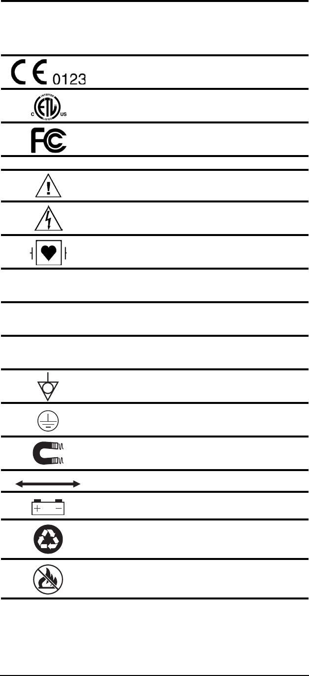
Regulatory Symbols
European Community Mark
ETL Mark
FCC (US Federal Communications Commission)
Mark
Safety Symbols
ATTENTION! Refer to Operation Manual for
Information
Shock Hazard
Type CF Equipment, defib proof
Indicates no protection against ingress of water
(remote display)
Identifies the degree of protection against fluid as
drip-proof (main monitor)
Identifies the degree of protection against fluid as
drip-proof (power supply)
Equipotential Terminal
Protective Earth
Indicates the MR magnet and power
Indicates distance between MR magnet and monitor
Indicates the presence of a battery
Recycle batteries following hospital protocols and
local environmental regulations.
Do not incinerate! Keep away from fire or other
sources of extreme heat.
IPX0
IPX1
IPX2
Page xiv
MEDRAD
Veris
8600
Symbol Definition
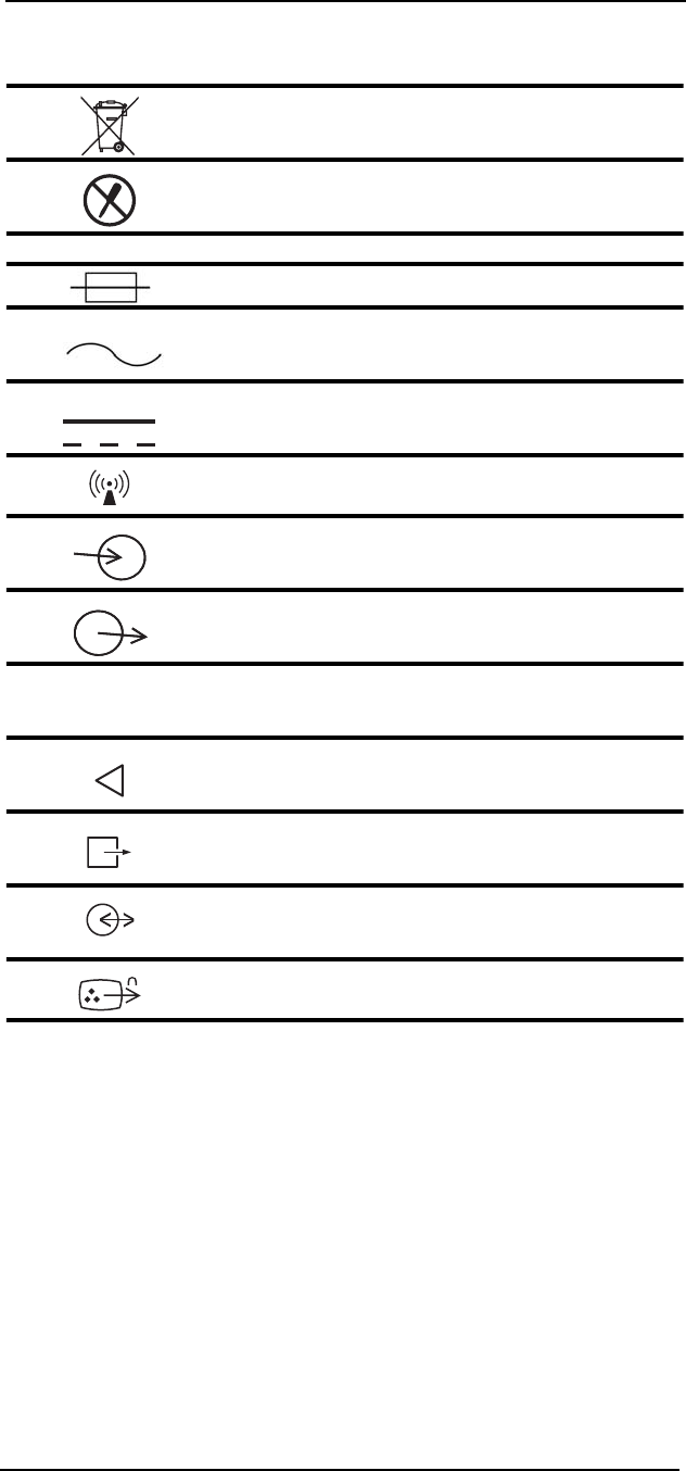
Dispose of batteries properly in accordance with
hospital and local regulations.
Risk of electrical shock! Do not remove cover.
Refer servicing to qualified personnel.
System Symbols
Fuse
Alternating Current (AC)
Direct Current (DC)
Wireless Device
Port Symbols
Signal Input
Signal Output
Digital Output
Air Intake
Scavenging Port
Communication Port
Video Out
IOIOI

Page xv
Symbols
Miscellaneous Symbols
Symbol Definition
Technical Support Phone Number
Manufacturing Contact
Serial Number
Part Reference Number
Place this side against the skin (Blood Pressure Cuff)
Placement of the cuff over the brachial artery.
Single use device only. Do not reuse.
SN
REF
2

Page xvi
Safety
Definitions
Definitions for Warning, Caution, and Note symbols:
Designates a possible dangerous situation.
Non-observance may lead to death or the most
severe injuries.
Designates a possible dangerous situation.
Non-observance may lead to minor injuries or
damage to the product.
NOTE: Indicates that important information follows, a tip that can help
you recover from an error, or point you to related details in the
manual.
Warnings
• Read this manual entirely before using the monitor.
• Inspect For Damage! User should inspect the system for signs
of damage. Do not use the system if failure is evident or
suspected.
• Possible burn hazard! Do not coil cables inside the MR scanner.
• Possible explosion hazard! Do not use the monitor in the
presence of flammable anesthetics. The equipment is not
suitable for use in the presence of a flammable anesthetic
mixture with air or with oxygen or Nitrous Oxide.
• Possible explosion hazard! Do not use the monitor in the
presence of gas mixtures which may be flammable.
• Cables, tubing, and lead wires may present a risk of
entanglement or strangulation! Verify safe and proper
positioning of these items at all times.
• Unapproved modifications to the monitor may cause unexpected
results and present a hazard to the patient.
• Risk of electrical shock! Do not remove cover. Refer servicing to
qualified personnel.
• All cords must have hospital grade plugs and be plugged into
hospital grade outlets. (The electrical installation of the relevant
room must comply with NFPA 70: National Electric Code or
NFPA 99: Standard for Health Care Facilities. Outside the
United States, the relevant room must comply with all electrical
installation regulations mandated by the local and regional
bodies of government).
• Do not bring tools containing ferrous material into the magnet
room. Risk of serious injury and/or damage to equipment can
occur.
WARNING
!!
CAUTION
!!
WARNING
!!

Page xvii
Safety
• Do not route gating cables near or within the scanning volume.
• Apply brakes to prevent movement.
• Do not re-use accessories labeled as single use. Risk of patient
contamination may occur.
• Improper disposal of batteries may result in explosion, leakage,
or personal injury. Do not open batteries. Do not dispose of
batteries in a fire. Follow all local regulations concerning the
disposal of spent Lead-acid and Lithium-Ion batteries or contact
MEDRAD for assistance.
• Connect only MEDRAD approved three-lead or five-lead ECG
cables from the patient to the ECG module. Do not connect any
other signal source to the ECG module.
• There is no defibrillator synchronization output on the Veris
monitor. Make no connections between the Veris and a
defibrillator.
• Leakage currents may increase if other equipment is
interconnected to the patient. The increased leakage currents
may present a hazard to the patient.
• PACEMAKER PATIENTS: This device does not include
pacemaker spike rejection capability. Heart rate readouts
derived from the ECG patient connections are likely to display
erroneous high or erratic rates when a pacemaker is in use.
Keep pacemaker patients under close surveillance. For
pacemaker patients it may be advisable to select the SpO2
function as the primary heart rate source.
• High Frequency (HF) surgical equipment may affect ECG
operation. The system is not designed to operate in the
presence of ESU interference. The patient may be burned.
Patient burns can also result from defective HF surgical
equipment neutral electrode connection.
• The heart rate calculated by the monitor may be affected by
cardiac arrhythmia.
• Do not take the remote display or the ECG module battery
charger into the MR scanner room. These contain ferromagnetic
material and can be strongly attracted to the magnet causing a
safety hazard.
• Do not use with an open MRI. Use of the monitor in an open
MRI may result in erratic or unavailable monitoring.
• Do not stand or sit on monitor accessories tray. Possible injury
can result from falling.
WARNING
!!

Page xviii
MEDRAD
Veris
8600
• Do not lift the monitoring system by the tray. Possible injury can
result from heavy weight.
• U.S. Federal law restricts this device to sale by or on the order
of a physician.
Cautions
• Use only accessories designated for use with this monitor. Use
of accessories not designated for use with the Veris monitor can
cause inaccurate measurements and/or a safety hazard for the
patient.
• Equipment accuracy may be affected at extreme temperatures.
• Do not store equipment at extreme temperature. Temperatures
exceeding specified storage temperatures could damage the
system.
• Avoid routing the DC cable through the magnet room door.
Possible damage can occur to the DC cable and/or the scanner
room door.
• Do not press on the keys with sharp or hard objects. This could
damage the keys. Use only your fingertips to press on the keys.
• Changes or modifications not expressly approved by MEDRAD,
Inc., may void the user's authority to operate the equipment and
may also void the warranty.
• Do not use the monitor in the path of a Linear Accelerator or
Positron Emission Tomography (PET) scanner beam. This could
result in inaccurate physiologic parameters or waveforms.
• Transporting the monitor in a mobile scanner trailer can lead to
damage from shock, vibration, or extreme temperatures.
• Do not allow the conductive parts of the patient electrodes to
contact other conductive parts, including ground (earth).
• Do not tip the monitor. Possible injury can result from falling.
• Do not stand on power supply enclosure. Injury from tripping or
falling can occur.
• Do not stand on the base. Possible injury can result from falling.
• Do not pinch cables between the table and the bore. This can
damage the cables.
• Do not roll the monitor over or step on cables. This can damage
the cables.
WARNING
!!
CAUTION
!!
Page xix
Safety
• Do not bend fiber optic cables too tightly. Follow cable
manufacturers specifications for bend allowance.
• If a probe falls on the floor or into liquid, clean the probe
following proper cleaning methods. If the probe is not properly
cleaned, inaccurate physiologic parameters or waveforms may
result.
• Do not place more than 40 pounds (18 kg) on the tray.
Leakage Current
The monitor complies with leakage current limits required by medical
safety standards for patient-connected devices. The Veris monitor
conforms to EN 60601-1 standards. A hazard caused by the
summation of leakage currents is possible, when several pieces of
equipment are interconnected.
Voltage Fluctuations
When operated in the line voltage range specified in this manual any
minor fluctuations will have a negligible effect. Very low line voltage
will cause the monitor to revert to battery power. Very high line
voltage may cause damage to the charger circuits. The monitor is
designed with circuitry that will turn the unit off before spurious
readings can be caused by a low battery condition.
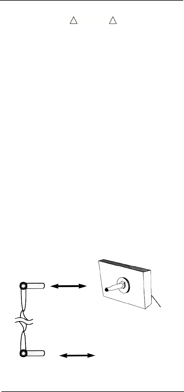
Equipotential Ground
Health care providers and patients are subject to dangerous,
uncontrollable compensating currents for electrical equipment.
These currents are due to the potential differences between
connected equipment and touchable conducting parts as found in
medical rooms.
The safety solution to the problem is accomplished with consistent
equipotential bonding. Medical equipment is fitted with connecting
leads made up with angled sockets to the equipotential bonding
network in medical rooms.
CAUTION
!!
Connection Lead
(Socket)
Equipotential
Connector
Equipotential
Terminal
Main
Body
Earth Ground

Page xx
MEDRAD
Veris
8600
Software Error Related
Hazard Mediation
MEDRAD, Inc., has quality control practices and procedures in place
to review potential hazards as they relate to software. The monitor
utilizes a four-digit year for all date, time, and leap year calculations.
Potential Interference
This device has been tested to 60601-1-2 specified levels for
emissions of and immunity to electrical interference. External
disturbances which exceed these levels, such as motor driven tools,
may cause operational issues with this device. Other devices which
are sensitive to a lower level of emissions than those allowed by
IEC 60601-1-2 2nd Edition may experience operational issues when
used in proximity to this device.
MAGNETIC FIELDS
Always position the Veris Base, Base Plus, and Cardiac monitors at
or outside the 2000 Gauss line. Always position the Veris Anesthesia
monitor at or outside of the 500 Gauss line. This monitor is designed
specifically for MR compatibility and is 1.5 and 3T compatible. It will
not cause interference with MRI image quality, nor will its
performance be affected by the magnet field.
The "T" wave may become excessively large or inverted with the
patient in the magnetic field. This effect is due to hemodynamic flow
induced voltage and may interfere with QRS detection. Try other
leads and/or electrode placements for best results.
CONDUCTED TRANSIENTS
The monitor conforms with IEC 1000-4-4, and IEC 1000-4-5 for
conducted transients, and will operate with negligible adverse effects.
X-RAY, CT, ULTRASOUND, AND/OR NUCLEAR MEDICINE
The monitor will operate with negligible adverse effects in these
environments. However, the monitor should not be placed directly in
the radiated beam, which could damage the internal electronics of the
monitor.
OTHER INTERFERENCE
There is a negligible adverse effect to the monitor from infrared
energy and defibrillation.
Use of Anesthetics
Do not use this device in conjunction with flammable anesthetics
such as cyclopropane and ether. The monitor can sample from pure
oxygen environments, but the monitor itself should never be placed
inside an oxygen rich environment, such as an oxygen tent or gas
containment apparatus. Proper anesthetic gas waste recovery should
be used.
Biocompatibility
All patient-contact or user-contact materials in this monitor and it's
accessories have passed ISO 10993-5, -10, & -11 biocompatibility
tests or have been in use in clinical environments in large numbers
over an extended period of time predating these standards.

Page xxi
Safety
Probes Fall in Fluids
Whenever probes fall and land in fluids, clean the probes according to
the cleaning instructions in “Cleaning and Disinfecting” on page A-1.
FCC and Industry Canada
Compliance
This device complies with Part 15 of the FCC Rules.
Operation is subject to the following two conditions:
1. This device may not cause harmful interference, and
2. This device must accept any interference received, including
intereference that may cause undesired operation.
• Changes or modifications not expressly approved by the party
responsible for compliance could void the user’s authority to
operate the equipment.
The term “IC” before the certification/registration number only
signifies that the Industry Canada technical specifications were met.
IC: 5338A-CSI8600
Audible Pulse Tone
The amplitude of the audible pulse tone remains constant regardless
of changes in patient parameter measurements.
Disposal Accessory Disposal
Discard disposable medical waste according to your institution's
policies and procedures to prevent biological contamination. See
“Disposal” on page A-7.
Latex Content
This MEDRAD product (patient monitors and approved accessories)
are free from latex in any location that may result in patient contact.
WARNING
!!

Page xxii
Introduction
Description
The VerisTM 8600 patient monitor is designed for use in the MRI
environment. It interprets and displays physiologic data as waveforms
and numeric information which, depending on the configuration of the
system, may include ECG, NIBP, SpO2, CO2, respiration,
temperature, O2, anesthetic gases, and IBP. User defined alarm limits
and alerts may be set for each parameter. Monitored parameter data
is stored as tabular trend information and may be printed or
downloaded.
Intended Use
The system is intended to monitor physiological parameters of
patients within any health care environment, specifically in the MR
environment. The user, responsible to interpret the monitored data
made available, will be a professional health care provider.
Physiological data, gas monitoring, system alarms, and patient
analysis will be available to the care provider from the monitor.
The monitor shall be MR compatible based on the FDA guidelines for
equipment to be used in MR.
There are two distinct needs for patient monitors in MR:
• Vital signs monitoring, to monitor medically unstable patients or
patients under conscious sedation, as required by the JCAHO.
• And, provide image gating, to gate image acquisition to a
physiological parameter, such as the cardiac cycle.
There is the additional requirement for the accurate function of the
equipment in the MR environment. The monitor used in the scan
room shall not be affected by the radio frequency pulse or gradient
fields and shall not produce any RF interference on the image.
The monitor (including accessories) shall be capable of monitoring a
full range of patients from neonate to adult.

Page xxiii
Introduction
Clinical Use
This manual provides separate sections for measured parameters.
These sections provide instructions for patient connections and
monitoring. The caregiver is expected to be fully familiar with patient
monitoring techniques and with the functions of this monitor before
using it with a patient.
This system is designed to only monitor one patient at a time per
monitoring system.
Before you Begin
Protect yourself and your patient. Read the precautions for each
measured parameter that appears in each measured parameter
section.
These instructions describe the use of the basic sampling devices
and accessories that come with your monitor. An extended list of
approved accessories can be found in “Accessories” in Appendix D of
this manual.
The monitor should always be checked by the caregiver before use
for actual patient monitoring. Perform the following procedure before
using the monitor with each patient.
1. Make sure the monitor has been fully charged before use.
Check that the AC (Mains) power cord is plugged in for long-
term monitoring situations.
2. Check the menus and default settings to confirm that the
monitor is setup correctly.
3. Examine the accessories for wear, damage or contamination.
Replace or disinfect the accessories as required.
4. Turn the desired monitoring modules to ON in the PARAMS
softkey window.
5. Select the correct mode of operation (Adult/Pediatric/Neonate)
by entering the patient size in the ADM/DIS softkey window.
• All accessories connected to the patient monitor must comply
with all applicable UL (Underwriters Laboratories) standards
and IEC standards for such products.
• Substitution of recommended sensor and sampling accessories
may cause inaccurate measurements and degrade patient
safety, or may damage the monitor.
CAUTION
!!
1 —1
1 — Panel Features
This section provides an overview of the
Veris
8600 monitor’s control
panels, switches, accessory connections, and communication
sockets.
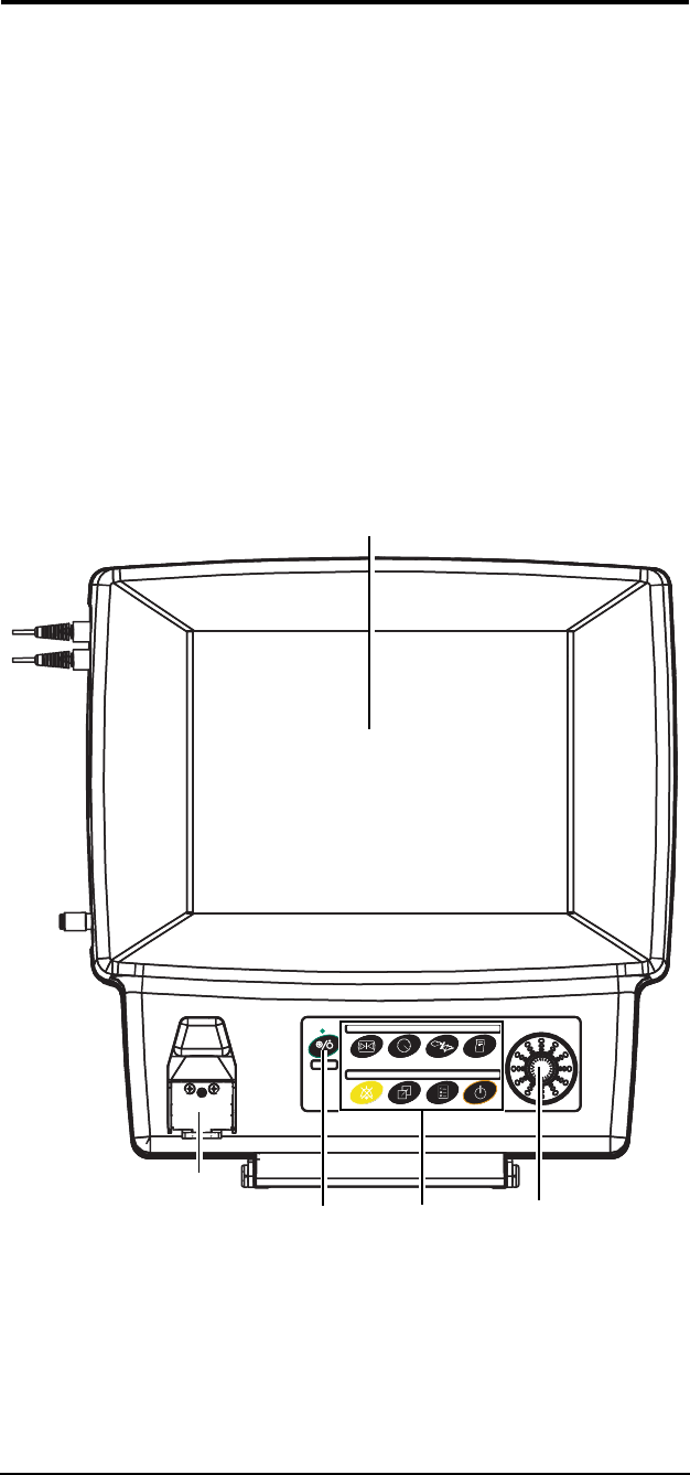
Front Panel
The front panels of the monitor and the optional remote display
feature a color flat-screen display. Located below the screen is the
primary control panel equipped with the power button, eight
dedicated function keys and a menu knob. Menu selections are
displayed on the screen and can be selected via the menu knob. The
keypad is push-button style, composed of a touch-sensitive
membrane.
The water trap receptacle is also located on the front of the main
monitor (Anesthesia units only).
Figure 1-1:
Veris
8600 Front Controls
Color Display
Menu
Knob
Power
Switch
Water Trap
Receptacle
(Anesthesia
Monitors only)
Keypad

MEDRAD
Veris
8600
1 —2
A green LED indicator is located above the power (ON/OFF) key. The
indicator is on if AC power is present.
Figure 1-2: Detail of Lower Front Panel
Menu Knob
The menu knob can be turned left or right to make selections from
any of the menus that appear on the front display. The selected menu
option can then be activated by pressing in on the menu knob.
Color Display
The display provides real-time waveform and numerical data of the
measured parameters. Additional menus and menu options which
may be selected and activated by the menu knob are also displayed
on this and the optional remote display screen.
Water Trap and
Gas Sampling Connection
The water trap connection is a feature on Anesthesia and Anesthesia
with Temperature models only. MEDRAD
Veris
monitors without gas
analysis capability have a blank plate in this location. The water trap
is easily accessed on the front of the monitor. The gas sampling line
is connected to the water trap and it is used for CO2, O2, N2O, and
agent monitoring. The sample line fitting is a standard female Luer-
lock connector when using the WaterChek™2+ water trap accessory.
Menu Knob
Function
Keys
Water Trap
AC Power
Indicator
Sampling
Line
Connection
1 —3
1 —Panel Features
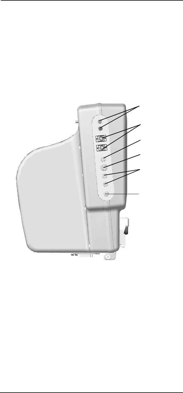
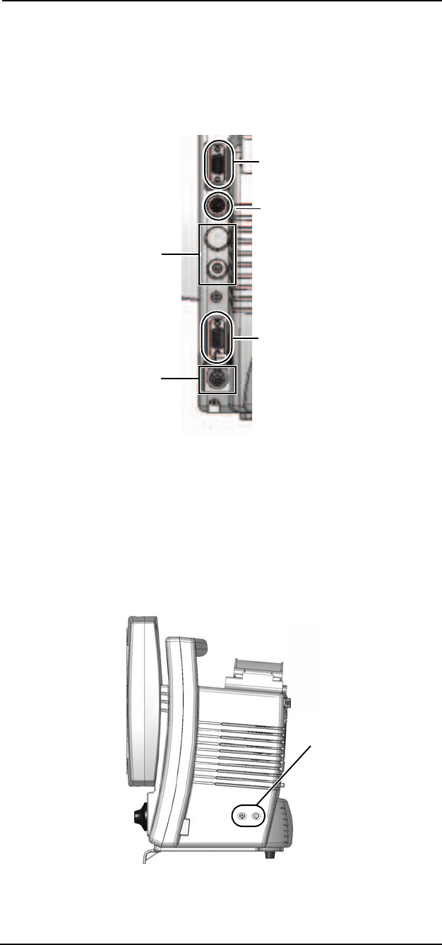
Left Side Panel (Main Monitor)
The left side of the main monitor has up to nine connections for
patient monitoring. The electrocardiogram (ECG), pulse oximetry
(SpO2), and the non-invasive blood pressure (NIBP) connections are
standard on all
Veris
8600 models.
All potential
Veris
main monitor connections are described in the
picture below.
The optional remote display has no patient connections.
More information about accessory connections can be found in the
patient monitoring sections of this manual.
Figure 1-3:
Veris
8600 Left Side
ECG Input/
Output
SpO2
NIBP
Temperature
IBP
Gating
Signal

MEDRAD
Veris
8600
1 —4
Communication Port
(Main Monitor)
There are two fiber optic ports at the bottom of the monitor. One is an
input port and the other an output port. These ports, on both the main
monitor and the remote display, are for fiber optic communication
between the main monitor and the remote display. See the
Installation Instructions for installing the fiber optic communications.
See “Figure 1-8:: Remote Display Fiber Optic Connections” on
page 1-7 for the location of the fiber optic ports on the remote display.
NOTE: These connections have protective covers that need to be
removed before use.
Figure 1-4: Main Monitor Fiber Optic Connections
Fiber Optic
Input and
Output
Connectors
1 —5
1 —Panel Features
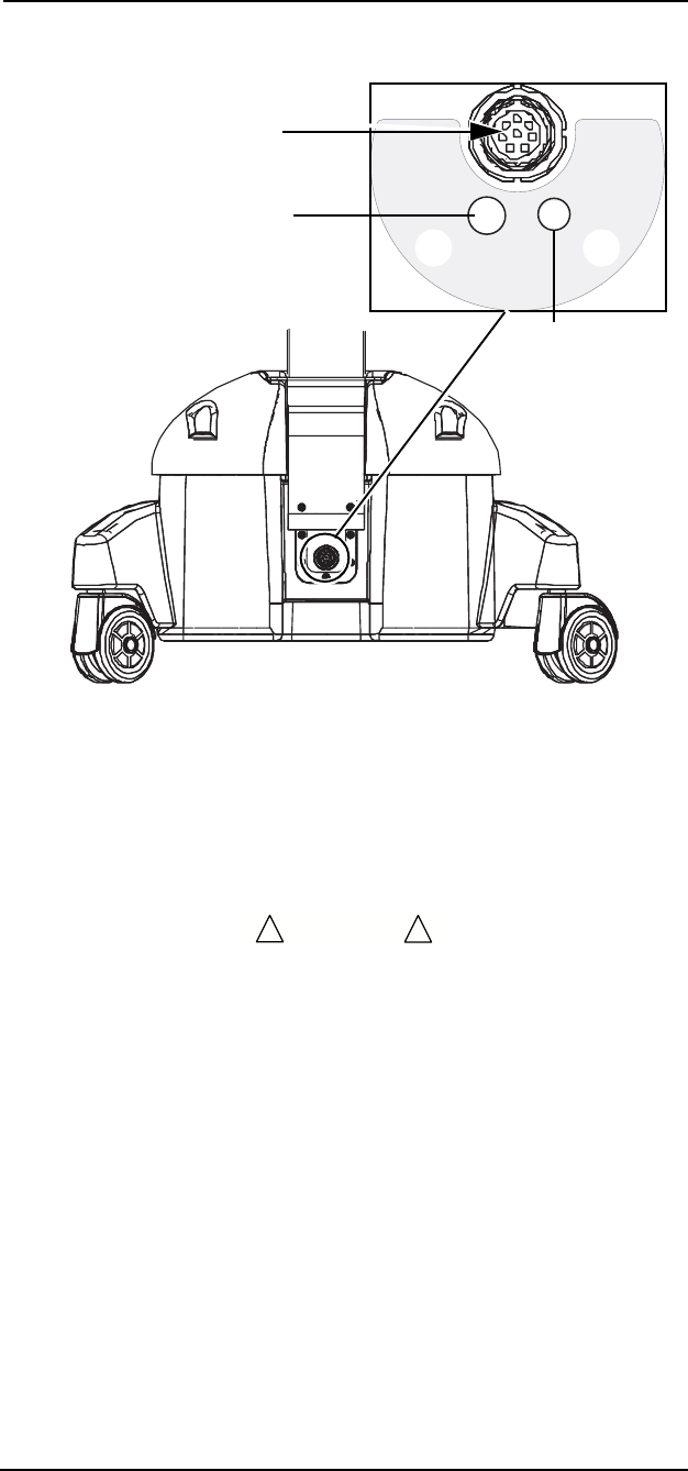
Main Monitor Base
Connections
Figure 1-5: Main Monitor Base Connections
Chassis Ground
The
Veris
monitor has an internal chassis ground.
DC Connection
A DC power cable connection is located at the center of the base of
the patient monitor. Attach the cable from the power supply in this
socket.
• Ensure that the cable from the power source to the monitor base
is placed in an area free from traffic to prevent tripping and/or
damage to the cable.
Exhaust Port
The exhaust port is located on the base of the Anesthesia monitor
assembly by the DC connection. The scavenging kit fits this nozzle.
Use the scavenging kit and a waste gas recovery system when
anesthetic agents are present in gas samples.
Air Intake Port
An ambient air intake port (located next to the exhaust port on the
base of the Anesthesia monitor assembly) is used for making zero
gas concentration calibrations. Do not block or attach anything to the
air intake port.
DC Connection & Exhaust Port
DC Connection
Exhaust Port
Air Intake
Port
CAUTION
!!
MEDRAD
Veris
8600
1 —6
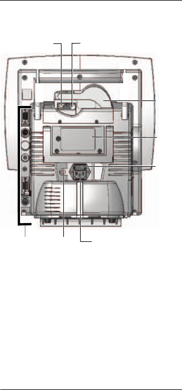
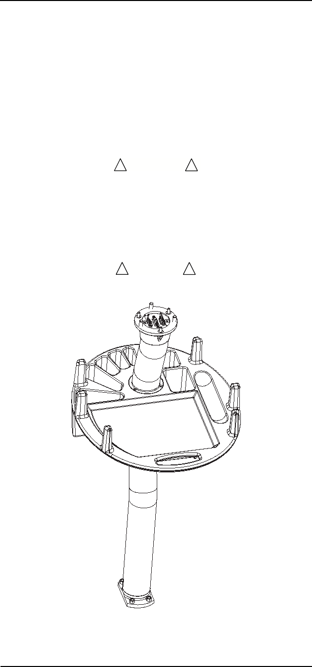
Remote Display
The remote display displays the patient data in another location.
Changes to the display can be made from the remote display and be
effected on the patient monitor.
Figure 1-6: Remote Display Rear View
Printe
r
Door
AC Power
Connection
Chassis
Ground
Communication
Connections
Printer Release
Lever Printer Feed
Advance
Servic
e
Access
Panel
Fuse
Access
Panel
1 —7
1 —Panel Features
COMMUNICATION PORTS (REMOTE DISPLAY)
There are three communications sockets available along the back
edge of the remote display. These connections provide links to
external printers, computers, and other medical devices. See
“Printing and Data Ports” in Section 12 for more information about
serial printing and communications
Figure 1-7: Communication Ports (Remote Display)
There are also two fiber optic ports on the right side of the remote
display. These ports, on both the main monitor and the remote
display, are for fiber optic communication between the main monitor
and the remote display. See the Installation Instructions for installing
the fiber optic communications.
NOTE: These connections have protective covers that need to be
removed before use.
Figure 1-8: Remote Display Fiber Optic Connections
COM Port 1
Serial DB-9
COM Port 2
Mini DIN 8
Video Port
Not Used
Not Used
Fiber Optic
Input and
Output
Connectors
MEDRAD
Veris
8600
1 —8
Printer
This printer door provides quick access to the internal printer paper
spool. The printer lever releases the printer rollers for removing
jammed paper. The knob can be turned to feed paper. See “Printing
and Data Ports” in Section 12 for additional printer information.
Printers are only available on
Veris
8600 remote displays.
Accessory Tray
The monitor has an integral accessories tray where the user can
store and hang accessories.
• Do not stand or sit on monitor accessories tray. Possible injury
can result from falling.
• Do not lift the monitoring system by the tray. Possible injury can
result from heavy weight.
• Do not place more than 40 pounds (18 kg) on the tray.
Figure 1-9: Accessory Tray
WARNING
!!
CAUTION
!!

1 —9
1 —Panel Features
Veris
8600 Configurations
There are six factory-set configurations and one optional remote
display available. See below for configuration options.
The instructions in this manual cover the operation of each of the
option packages listed above. For those models that do not include a
particular monitoring module (i.e. Agents), the system functions as if
that module is turned off.
Number Description Features
3011991 Base MR Monitor Standard 3-lead ECG, SpO2, and NIBP
3011992 BasePlus MR Monitor Base plus Remote Display
3011993 Cardiology configuration Base plus 5-lead ECG, ECG Gating,
SpO2 Gating, IBP.
The Remote Display is optional.
3011994 Cardiology with Temperature Cardiology plus Temperature.
The Remote Display is optional.
3011995 Anesthesia configuration Base plus 5-lead ECG, ECG Gating,
SpO2 Gating, IBP, O2, CO2, N2O,
agents.
The Remote Display is optional.
3011996 Anesthesia with Temperature Anesthesia plus Temperature.
The Remote Display is optional.
3010482 Remote Display Remote display with printer and fiber
optic communications.

2 —1
2 — Monitor Setup
This section provides an overview of the setup procedures for the
Veris
8600 monitor. Also see the appropriate chapters on patient
parameter monitoring for parameter setup information.
The monitor should be set up by the health care provider before using
it on patients:
• Load paper (if remote display is present). See paper loading
instructions in “Changing Printer Paper” on page 12-7.
• Charge all batteries (ECG module battery, main monitor
batteries.)
Preparations such as charging the batteries should be performed if
the monitor is new.
Battery Power
The monitor base contains two lead-acid gel batteries that when fully
charged provide a minimum of ten hours of operational use.
Charging the Battery
The
Veris
monitor is battery powered. The monitor internally
recharges the battery when it is connected to the power supply. The
monitor can operate in continuous use for a minimum of 10 hours on
a fully charged battery. Charge the battery from the power supply
over night for approximately 12 hours.
• If the electrical integrity of the earth ground is in doubt, the
power cord should be disconnected and the machine should be
operated from its internal electrical power source.
• Explosion hazard. Keep lighted cigarettes, sparks, and flames
away from the battery.
• Avoid contact with battery acid! The batteries contains sulfuric
acid electrolyte which can cause severe burns and eye damage,
as well as illness from sulfur oxide fumes. Use necessary
precautions when servicing batteries.
• Do not short circuit the battery terminals. The resulting high-
current discharge can cause burns.
• Do not operate the monitor with discharged or defective
batteries. Monitor failure could occur during AC power loss
which can compromise patient safety.
• Do not use the monitor if the batteries are missing.
WARNING
!!

MEDRAD
Veris
8600
2 —2
The
Veris
monitor can function on AC or battery power. MEDRAD
recommends that batteries be fully charged at all times. If the
batteries are insufficiently charged, battery life is degraded and
shortened. If defective batteries are suspected, contact MEDRAD
Service or your local representative.
Battery Indicators
The battery icons are located on the lower portion of the main screen
as described in “Screen Display and Interface” on page 2-5. The
battery icons change color to indicate the status of the batteries and
appear when using DC (battery) or AC (Mains) power.
When AC is connected to the monitor (green light above ON/OFF key
is lit), the battery icon colors are:
Amber: Battery is charging.
Green: Battery is fully charged.
When AC is not connected to the monitor (green light above ON/OFF
key is not lit), the battery icon colors are:
Green: Battery life is greater than 1 hour.
Yellow: Battery is weak. (less than 1 hour and more than 15
minutes of charge remains). A LOW BAT message
also appears.
Black: Battery is nearly drained. (less than 15 minutes of
charge remain). The LOW BAT message remains.
While using battery power there is a short delay between a change in
battery status and the updated display of the battery icons.
If the monitor is currently operating under AC power, the monitor may
take up to two minutes to display a change in battery status.
The monitor also displays the battery status for the ECG module in
the heart rate (HR) parameter box. The battery icon colors are:
Green: Battery life is greater than seven (7) hours.
Yellow: Battery life is less than seven (7) hours. Charge the
module battery soon
Black: This can indicate the ECG module is not connected
to the monitor. Verify the module is connected to the
monitor.
If the module is connected to the monitor, the battery
is drained. ECG module will not operate. Charge the
module battery immediately.
2 —3
2 —Monitor Setup
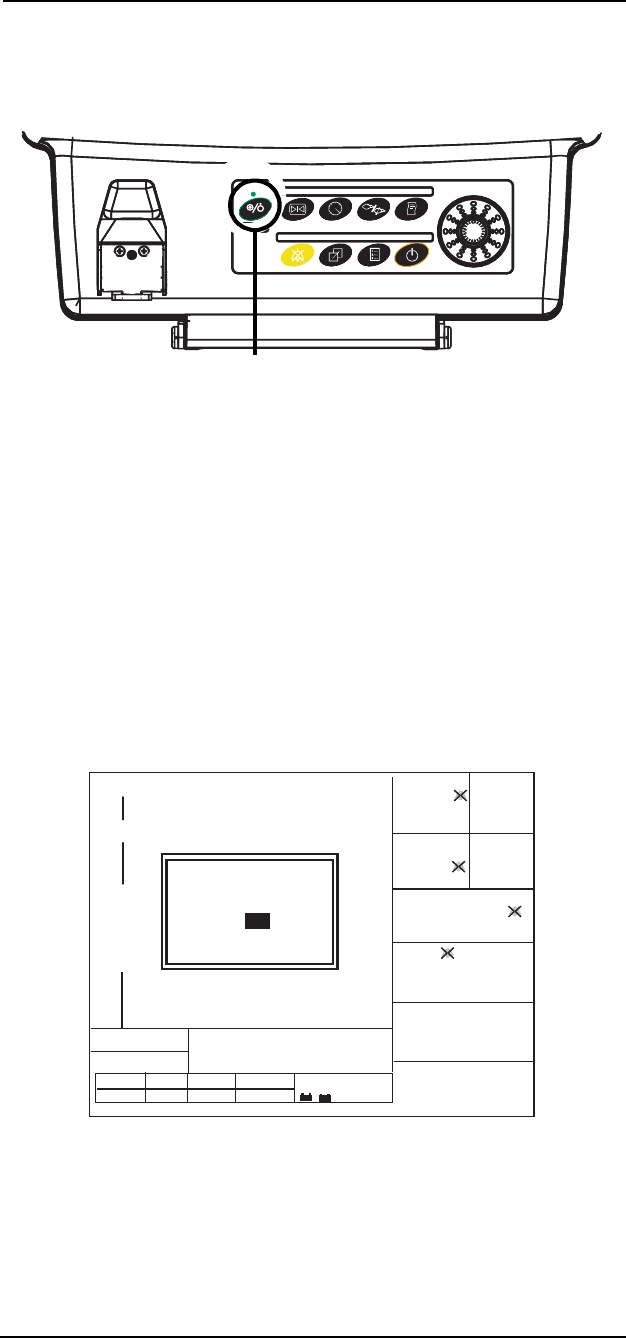
System Start and
Auto-calibration
To power up the main monitor, press the ON/OFF key located on the
front, left side of the control panel. If your system has a remote
display, power is applied via the same key on that component.
Figure 2-1: ON/OFF Key
Immediately upon power up, the monitor displays the
Veris
splash
screen. The software version appears on the screen. For systems
with a remote display, a paper feed automatically activates.
• The informational message NO ADMIT is reserved for future
use.
• Audible alarms are suspended for each parameter until the first
valid measurement has been taken for each parameter. Visual
alerts are always active.
• If a patient had been previously admitted by the monitor, a
notice message RESUME MONITORING appears in a yellow
box. Press the knob to continue monitoring with the current
patient. Select NO to change the patient.
Figure 2-2: “Resume Monitoring” Dialogue Box
ON/OFF Key
ALARMS PARAMS DISPLAY
ALARMS PARAMS DISPLAY
Adult
Adult
V000 - NO ADMIT
V000 - NO ADMIT
SPO2: SENSOR
SPO2: SENSOR
ZERO IP1
ZERO IP1
ZERO IP2
ZERO IP2
ADM/DIS CONFIG PRINT
ADM/DIS CONFIG PRINT
14:12:59
14:12:59
SpO2
SpO2
II
II
0
0
20
20
T1
T1
T2
T2
%
x1
x1
x1
x1
x2
x2
aVR
aVR
CO2
CO2
CO2
CO2
EXP
EXP
INS
INS
INS
INS
INS
INS
MAP
MAP
CYCLE OFF
CYCLE OFF
200
200
1mV
1mV
ECG
ECG
SpO2
SpO2
IBP1 ART
IBP1 ART
mmHg
mmHg
mmHg
mmHg
150 ml/min
150 ml/min
IBP2 CVP
IBP2 CVP
HR
HR
BPM
BPM
RESP Br/m
RESP Br/m
1mV
1mV
--
--
--
--
--
--
-
-
--.-
--.-
--.-
--.-
--
--
--
--
(---)
(---)
O2 HAL
O2 HAL
GAS
GAS
ISO
ISO
%
%
17 0.4 1.1
17 0.4 1.1
21 2.3 3.8
21 2.3 3.8
---/---
---/---
- +
+
ART1
ART1
CVP2
CVP2
---/---
---/---
(---)
(---)
Resume Monitoring
Same patient? YES
- +
+

MEDRAD
Veris
8600
2 —4
The monitor is comprised of a number of modules which measure
physiologic parameters. Some modules such as the oximeter are
ready for use within seconds of power up. Others such as the gas
bench take a few minutes to equilibrate.
Sensor and Probe Messages
Depending on the accessories attached to the monitor upon start up,
various messages concerning detached sensors and probes appear.
These are only visual alarms until valid measurements are taken by
the accessories, after which a low level alarm sounds when the
sensors and probes are disconnected.
NOTE: LEADS OFF messages can be set by the user to be Low,
Medium, or High level alarms.
If sensor and probe messages from unused modules become a
distraction, these messages may be eliminated by turning the
respective module off. The OFF settings are located in the PARAMS
windows described in “PARAMS Softkey (Physiological Parameters)”
on page 2-21.
Units with invasive blood pressure capability indicate that either there
is no transducer attached (NO XDUCER) or that the transducer has
not been calibrated by the user (NOT ZEROED). In either case it is
not necessary to attach or zero the transducers in order to use the
other features of the monitor.
Gas Calibration
The agent gas detector may require a short warm up period and auto-
calibration sequence similar to an internal capnometer. The message
AGT:WARMING appears in the information message area. The
informational message AGT:MANUAL or AGT:AUTOMATIC also
appears indicating that the monitor is in either manual or automatic
primary agent identification mode. AGT: AUTO CAL indicates that the
agent calibration is in progress.
Respiration waveforms, capnogram, and numerical breath rate are
available in one minute from applying power to the monitor. The
monitor reaches full accuracy for agent concentrations in less than 20
minutes.
If the
Veris
system fails to auto-calibrate upon power up, the message
AGT:BAD CAL appears. If the system continues to fail auto-
calibration, contact MEDRAD Service or your local representative.
The oxygen monitoring module also requires auto-calibration, which
is performed at the same time as the agent bench calibration. If the
O2 module fails to calibrate, the message O2:SENSOR appears.
Upon successfully completing auto-calibration the monitor displays
values for monitored gases.

2 —5
2 —Monitor Setup
Screen Display and Interface
The display is divided into dedicated areas for data and interface
functions. The left side of the screen is reserved for waveform (up to
six) or graphic display. The uppermost waveform slot is factory set for
ECG. The remaining five waveform slots can be configured by the
user. The alarm silence icon (2 minutes or permanent) is shown in
the upper right corner of the first waveform.
The far right column is dedicated to reporting numerical data, except
for NIBP and temperature which appear below the waveforms. The
color of each parameter is user selectable. Therefore, any given
waveform and its corresponding numeric data appear in the same
color.
Figure 2-3: Screen Diagram
Main menu shown in grey above. The arrangement of the numerical
parameter boxes varies depending upon the waveforms selected to
be viewed and the waveform slot selected for the waveform. The
parameter box displays to the right of its corresponding waveform if
displayed in a waveform slot. The screen display is the same on the
patient monitor and the remote display. Changes to the display can
be made at the patient monitor or at the remote display.
The bottom portion of the display has space dedicated to the
following message types and functions.
• The main screen menu of selectable softkeys.
• Two message lines for alarms and alerts.
• A system status line for battery status and patient size mode.
• The patient information bar, date stamp, and clock.
NIBP Parameters
Temperature 1
Temperature 2
Waveform Slot 1
Waveform Slot 2
Waveform Slot 3
Waveform Slot 4
Waveform Slot 5
Waveform Slot 6
ALARMS PAR AMS
ADM/DIS
DISPLAY
CONFIG PRINT
ZERO IP1
ZERO IP2
Priority Alarms
Info Messages
System Status
Patient Data Date Time
Heart Rate
Numerical
Parameters
SpO2Respiration
IBP Channel 1
Parameters
IBP Channel 2
Parameters
CO2 Numerical
Parameters
Gas Numerical
Parameters
Remote
Communication
Gating
ECG Module
Battery
Status
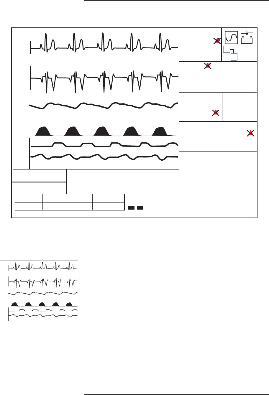
MEDRAD
Veris
8600
2 —6
Figure 2-4: Sample Interface Screen
Waveform Slots
The monitor has the capability to display up to six waveforms
simultaneously.
The first trace is factory set to only display an ECG waveform. The
user may select the lead type for this trace. All other displayed
waveforms are user selectable.
Each waveform slot displays the parameter or source along the left
edge of the screen. Amplitude bar and range are shown at the
beginning of the slot if applicable to that type of waveform. The color
of each waveform may be selected by the user. The waveform slots
can be combined to form double high waveforms and waveforms can
be cascaded to fill multiple slots. See “Double Height Slots” on
page 2-28 and “Cascaded Slots” on page 2-29 for details.
NOTE: The SpO
2
waveform display is not necessarily directly
proportional to pulse volume. The SpO
2
waveform display is not
automatically gain adjusted.
ALARMS PARAMS DISPLAY
ALARMS PARAMS DISPLAY
Adult
Adult
V000 - NO ADMIT
V000 - NO ADMIT
SPO2: SENSOR
SPO2: SENSOR
ZERO IP1
ZERO IP1
ZERO IP2
ZERO IP2
ADM/DIS CONFIG PRINT
ADM/DIS CONFIG PRINT
AUG-16-04 14:12:59
AUG-16-04 14:12:59
SpO2
SpO2
II
II
0
0
20
20
T1
T1
T2
T2
%
x1
x1
x1
x1
x2
x2
aVR
aVR
CO2
CO2
CO2
CO2
EXP
EXP
INS
INS
INS
INS
INS
INS
MAP
MAP
CYCLE OFF
CYCLE OFF
200
200
1mV
1mV
ECG
ECG
SpO2
SpO2
IBP1 ART
IBP1 ART
mmHg
mmHg
mmHg
mmHg
200 ml/min
200 ml/min
IBP2 CVP
IBP2 CVP
HR
HR
BPM
BPM
RESP Br/m
RESP Br/m
1mV
1mV
60
60
98
98
37
37
8
8
96.4
96.4
97.7
97.7
20
20
13
13
(125)
(125)
O2 HAL
O2 HAL
GAS
GAS
N2O
N2O
E
I
17 0.4 39
17 0.4 39
21 2.3 64
21 2.3 64
145/105
145/105
ART1
ART1
CVP2
CVP2
149/106
149/106
(127)
(127)
CO2
CO2
- +
NIBP AGE 21:13 min
NIBP AGE 21:13 min
mmHg
mmHg
%
Mixed ENF E 10.5 I 10.0
Mixed ENF E 10.5 I 10.0
- + - +
SpO2
SpO2
II
II
0
0
20
20
x1
x1
x1
x1
x2
x2
aVR
aVR
CO2
CO2
200
200
1mV
1mV
1mV
1mV
ART1
ART1
CVP2
CVP2

2 —7
2 —Monitor Setup
VISUAL ALARMS WITH WAVEFORMS
The waveform slots are also used to display physiological alarms that
will appear at the top center of each slot. For a high priority alarm the
color of the message is red. For a medium priority alarm, the color of
the message is yellow.
The bottom five slots may be covered by menus and messages.
Since the top waveform slot is dedicated to ECG, the ECG waveform
and the ECG high and medium priority messages are always visible if
ECG is currently being monitored and the top slot is active.
See “Visible Alarms” on page 3-2 for a complete description of visual
alarms.
SILENCE ALERT STATUS
The silence alert visual icon appears in the upper right area of the top
waveform.
• The silence icon shows a bell with an "X" and an infinity symbol
when the SILENCE hard key has been pressed and held for
more than two seconds.
• The Alarm Suspend icon shows a bell with an “X” and the words
2 Min when the SILENCE hard key has been momentarily
pressed.
ALARM INHIBIT
The alarm inhibit icon appears in the parameter boxes when one or
more of an individual parameter’s alarms are turned OFF.
ECG WAVEFORM
The lead number and scale setting are displayed in the top left corner
of each slot set for ECG waveforms. The amplitude bar, shown in
white, indicates the scale in millivolts (mV).
SPO
2
WAVEFORM
The waveform is auto ranging where the monitor attempts to keep the
waveform centered in the slot at all times. No amplitude bar is shown.
CO
2
WAVEFORM
The CO
2
waveform, capnogram, is always displayed in percent
regardless of the units selected for displaying the numerical data. The
maximum range of the capnometer waveform is 12.5%.
BREATH BY BREATH BAR GRAPH (B×B)
The breath by breath bar graph is a method of representing the
concentration of CO
2
at the end of each breath. The data is always
displayed in percent with a maximum range of 12.5%.
O
2
WAVEFORM
The maximum range of the oxygen waveform is 100%. The units are
always in percent.

MEDRAD
Veris
8600
2 —8
PRIMARY AGENT WAVEFORM
The primary agent waveform is displayed in percentage only as is the
display for primary agent numerical data. The waveform is auto-
ranging within the slot. Secondary agents are not displayed as
waveforms.
NITROUS OXIDE (N
2
O)
The N
2
O waveform is derived from the agent detector of the
Veris
monitor.
IBP WAVEFORMS
The labels identifying the source of the IBP waveforms appear
between the upper and lower range values at the beginning of the
waveform.
The waveform has both manual and auto-ranging features. The
selected range appears at the left side of the waveform. The scaling
for IBP slots are locked at x1 and cannot be changed. Use the range
settings to adjust the appearance of the waveform on the screen. See
“Alarms and Messages” in Section 3 for details.
Selectable IBP sites are as follows:
• Arterial (ART)
• Pulmonary Artery (PA)
• Central Venous (CVP)
• Right Atrial (RA)
• Left Atrial (LA)
• Intracranial (ICP)
• Left Ventricle (LV)
• Right Ventricle (RV)
There are two IBP channels. The color of each channel can be
selected independently.
If the amplitude of the waveform exceeds the selected range the
waveform is clipped. An informational level alarm OFF SCALE
appears in the Info Messages Box of the main screen display.
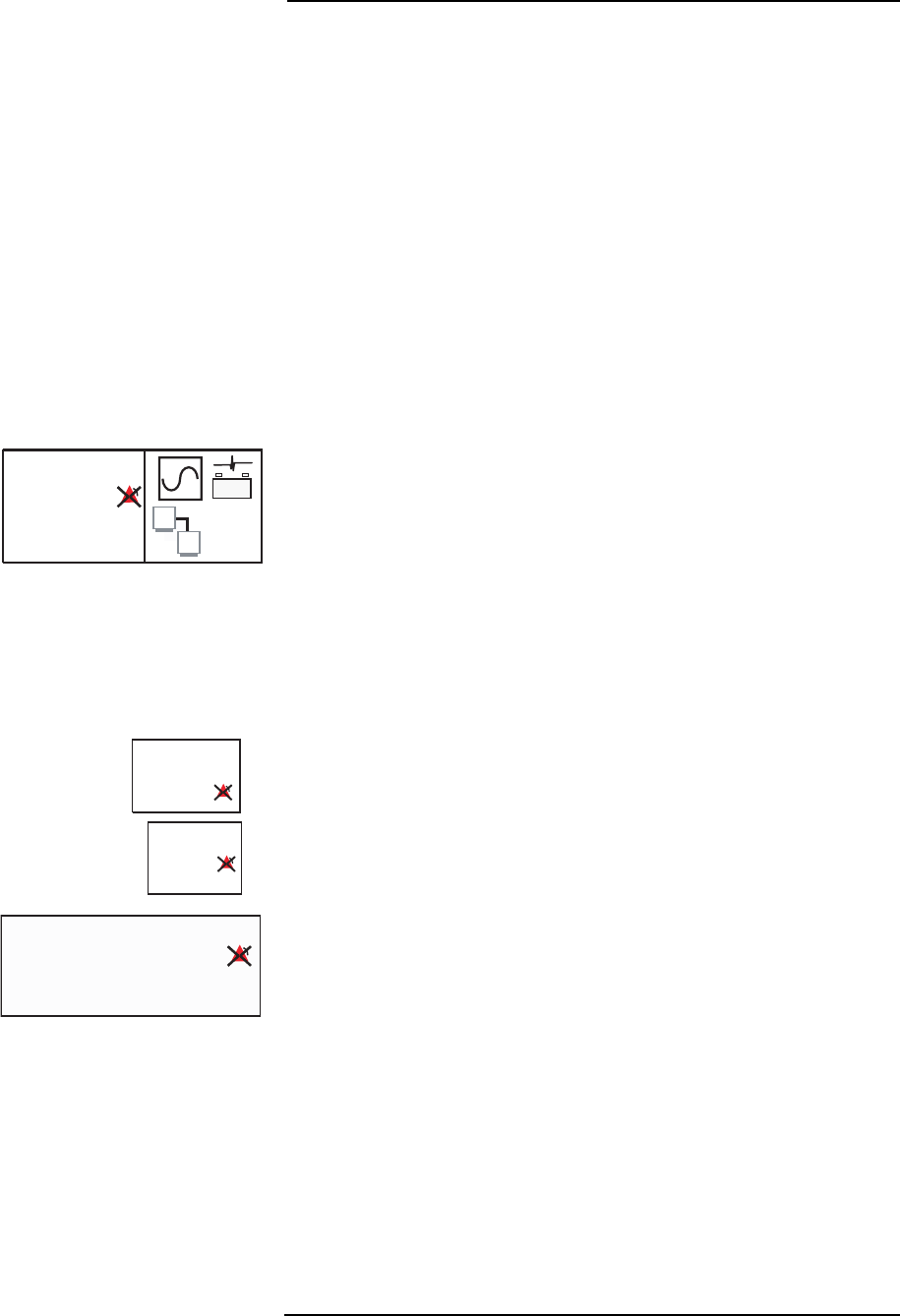
2 —9
2 —Monitor Setup
Numerical Parameter Boxes
The numerical parameter box area is directly to the right of the
waveform area. The area is broken into seven numerical boxes.
There are three additional numerical boxes below the waveforms.
The numerical parameter boxes display the measured value of the
vital sign being monitored, the unit of measure, and parameter-
dependent information (such as the source for the heart rate or
inspired/expired values for gases).
If a module is turned off in the PARAMS menu, the numerical
parameters are replaced by the word OFF in each location. Smart
parameters such as heart rate switch to another available module if
possible. An alarm inhibit icon appears in the upper right corner or
right center of a parameter box if an alarm limit is set to OFF. The
alarm inhibit icon is red with a white “X” indicating that an alarm is
turned OFF.
ECG BOX
The top parameter box, in the upper right hand corner, is dedicated to
display the heart rate. The source of the heart rate (i.e. ECG, IBP,
SpO
2
, or NIBP) is shown in the lower left corner of this box. The color
of the numeric display for heart rate matches the color of the
waveform source data.
The right half of the ECG parameter box displays the gating output,
the ECG module battery status, and an icon indicating that the
monitor and remote display are communicating. The color of the
gating icon matches the color of the waveform and numerical data of
the source (i.e., ECG gating reflects the color of the ECG waveform
and numerics).
SPO
2
BOX
The SpO
2
box displays the oxygen saturation in percent.
RESPIRATION BOX
The Respiration box, to the right of the SpO
2
box, displays the
respiration rate and respiration source (i.e. CO
2
).
CO
2
BOX
This box displays numerical values for expired and inspired CO
2
. The
label EXP stands for expired (end-tidal) CO
2
and INS stands for
inspired CO
2
. The current Flow Rate is displayed in the upper right
corner.
ECG
ECG
HR
HR
BPM
BPM
60
60
- +
%
%
SpO2
SpO2
98
98
RESP Br/m
RESP Br/m
20
20
CO2
CO2
CO2 mmHg
CO2 mmHg
EXP
EXP
INS
INS
INS
INS
INS
INS
200 ml/min
200 ml/min
37
37
8
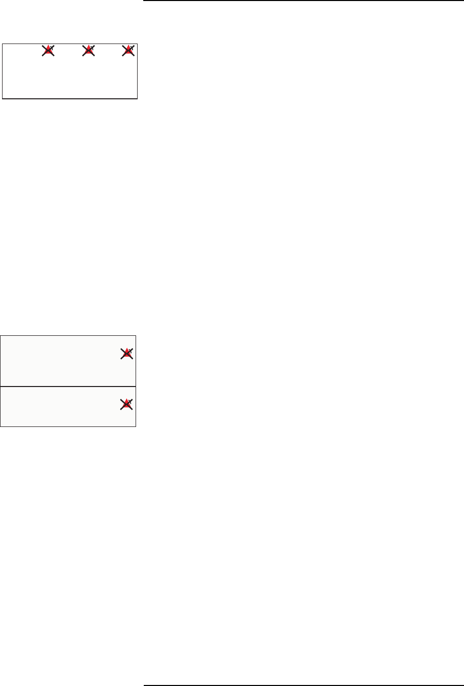
MEDRAD
Veris
8600
2 —10
GAS BOX
Numeric data for oxygen and agent gases appear in the same box.
The oxygen value is listed first followed by the primary halogenated
agent and nitrous oxide concentrations. The top line lists expired
values and the second line lists inspired values. Values are always
shown in percent. An alarm inhibit icon displays to the right of each
header to indicate alarm limits set to OFF.
The label Mixed appears before secondary agent concentrations
listed at the bottom of the gas parameter box. This indicates that
more than one agent is detected in the system and measures the
secondary agent detected. The abbreviated name of the secondary
agent is located after the Mixed label.
The label Wrong appears before secondary agent concentrations
listed at the bottom of the gas parameter box. The system detects an
agent other than one set in the configuration of the system. If using
more than one agent, set the Agent to Monitor selection in the
PARAMS menu to Auto. The abbreviated name of the secondary
agent is located after the Wrong label.
If the internal gas features are shut off in the PARAMS menu, the
displayed values are replaced by the word OFF in each location.
IBP BOXES
The monitor displays the systolic, diastolic, and mean pressure
pulsatile waveforms. The systolic and diastolic values are shown in
large text. The mean value (MAP) is displayed below the systolic and
diastolic values in smaller characters. All MAP values are shown in
parenthesis.
Non-pulsatile waveforms have only a mean value. Non-pulsatile
waveforms mean values are shown in large text and are centered in
the box.
O2 HAL
O2 HAL
GAS
GAS
N2O
N2O
E
I
17 11.0 39
17 11.0 39
21 10.5 64
21 10.5 64
Mixed ENF E 10.5 I 10.0
Mixed ENF E 10.5 I 10.0
%
IBP1 ART
IBP1 ART
mmHg
mmHg
mmHg
mmHg
IBP2 CVP
IBP2 CVP
( 13)
( 13)
(125)
(125)
145/105
145/105
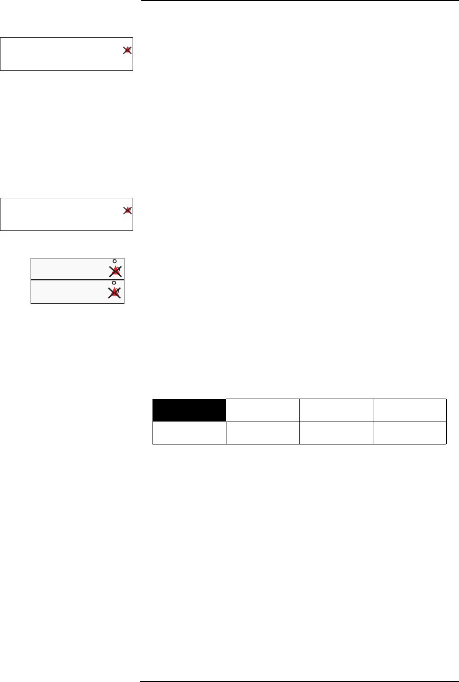
2 —11
2 —Monitor Setup
NIBP BOX
The NIBP numerical box is located near the center of the screen
below the waveforms. It displays the systolic, diastolic, and mean
pressure after a NIBP reading has completed. The systolic and
diastolic values are shown in large text. The mean value (MAP) is
displayed to the right of the systolic and diastolic values in smaller
characters. MAP values are shown in parenthesis.
When there is no valid reading, dashes are displayed. A valid reading
is dashed after 30 minutes. If a valid reading is displayed, the age of
the reading is displayed. After 30 minutes the age of the
measurement goes to dashes; if there is no valid reading, the age
also appears as dashes.
If a cycle time is set, the interval is displayed. Otherwise the cycle
time displays the word OFF in the NIBP box. If a cycle time is active,
the amount of time remaining until the next NIBP reading is
scheduled is displayed at the bottom right of the box.
TEMPERATURE BOXES
The top temperature numerical box is dedicated to temperature
channel 1. The lower box is dedicated to channel 2. The units (°F or
°C) appear in the upper right corner of each box.
Main Menu
The main menu area is directly under the Temperature and NIBP
boxes on the left-hand side of the screen. There are up to eight
selectable soft keys located on the screen as shown below.
NOTE: The
Veris
8600 screen layout depends on the configuration of
the monitor.
Figure 2-5: Main Menu
One of the eight softkeys is always highlighted. If the user pushes the
menu knob the menu window associated with the highlighted softkey
is displayed and the menu knob control goes to that new window.
Different soft keys are selected by turning the menu knob clockwise
or counterclockwise until the desired key is highlighted.
ZERO IP1 and ZERO IP2 do not access settings windows. On units
without IBP the ZERO IP1 and ZERO IP2 boxes are blank.
More information about the soft keys and their function is explained in
“Softkey Functions (Main Menu)” on page 2-14.
MAP
MAP
CYCLE OFF
CYCLE OFF
149/106
149/106
(127)
(127)
NIBP AGE
NIBP AGE
21:13
21:13
min
min
mmHg
mmHg
MAP
MAP
CYCLE 4:00:00 ET 3:45:37
CYCLE 4:00:00 ET 3:45:37
149/106
149/106
(127)
(127)
NIBP AGE
NIBP AGE
21:13
21:13
min
min
mmHg
mmHg
T1
T1
T2
T2
96.4
96.4
97.7
97.7
F
F
ALARMS PARAMS DISPLAY ZERO IP1
ADM/DIS CONFIG PRINT ZERO IP2

MEDRAD
Veris
8600
2 —12
Alarm and Message Areas
The two alarm lines are located under the NIBP numerical box. All
alarm and error messages for NIBP, respiration, and temperature are
displayed in this area. ECG, SpO
2
, CO
2
, O
2
, N
2
O, Agent, and IBP
high and medium alarms are displayed here if there is not an active
waveform associated with them. All low level messages are displayed
in the top alarm line. The bottom line is for informational messages
and advisory level alerts only.
The informational, low, and medium level alarm warnings are colored
yellow and the high alarm warning messages are red. For more
information about alarms see “Alarm Description” on page 3-1.
System Status Box
The system status box is located directly below the two lines reserved
for alarms and messages.
BATTERY WARNING ICONS
There is space reserved for two battery icons. The battery icons
represent the state of the internal rechargeable batteries. See
“Battery Indicators” on page 2-2 and “Charging the Battery” on
page 2-1 for a complete description of the icons and battery charging.
PATIENT SIZE MODE
The next item in the status line is the patient mode. This message lets
the user know what the patient size or mode the system is in: ADULT,
PEDIATRIC, or NEONATE. The default physiological alarm limits may
change depending on which mode is currently in use.
Patient Information and Clock
A Patient Information Bar runs along the bottom of the display. This
area displays the last name (12 characters), the first name (10
characters) and middle initial (one character) of the patient, the
hospital identification number for the patient (16 characters), and the
patient’s room number (five characters).
A clock appears to the extreme right of the patient information. This
displays both current date and time.
- +
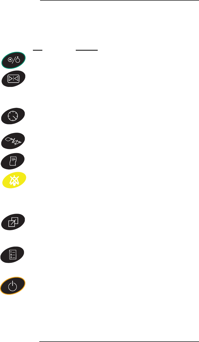
2 —13
2 —Monitor Setup
Keypad
There are nine keypad buttons, including the ON/OFF button and the
eight dedicated function keys. Some of the keys have two functions.
The primary function is activated with a momentary press of the key.
A secondary function, if present, is activated when the key is pressed
and held for two seconds.
Key Function
On/Off Power button. Press to activate the patient monitor
and press and hold to turn the monitor off.
Freeze A single press of this key freezes all waveforms on
the screen. Numeric data continues to be updated for
monitored parameters.
A second press of this key resumes continuous
waveform display.
NIBP Cycle/Stat Press the key momentarily to display the NIBP cycle
popup menu on the screen.
Press and hold this key to begin a Stat measurement.
NIBP NIBP measurement start key.
Press the key again to cancel an NIBP measurement.
Print Press once to begin printing or for serial output.
Press a second time to stop printing.
Silence Press this key momentarily to begin a 2 minute alarm
silence.
Press and hold the key to permanently silence the
alarms.
Press the key again, a second time, to resume
normal alarms.
Default Press this key momentarily to access custom default
profiles.
Press and hold the key to alter custom default profiles
(password MEDRAD
required).
Trend Displays the trend table when pressed momentarily.
Press the key to exit the trend window.
While the trend table displays, press and hold to
access the trend settings menu.
Stand By Press this key momentarily to enter standby mode.
Press the key again to exit the standby mode.
When any of the keys is pressed once, a single audible beep notifies
the user that a primary function has been activated. When a key is
pressed and held a double beep notifies the user that a secondary
function is selected.

MEDRAD
Veris
8600
2 —14
Softkey Functions
(Main Menu)
Softkeys are selected by turning the menu knob clockwise or
counterclockwise until the desired softkey is highlighted. In the
sample below the ALARMS softkey is highlighted indicating that the
alarm settings window displays if the menu knob is pressed.
Figure 2-6: Main Screen Menu
If the menu knob is rotated, any window associated with the
highlighted softkey is displayed when the menu knob is pressed. The
menu knob then controls scrolling through that new menu window.
NOTE: For monitors without invasive blood pressure the two softkeys
at the right end of the main menu are disabled and blank. The
invasive blood pressure zero buttons do not activate windows.
The top item (EXIT) on each menu window automatically highlights
when the window is activated. The user may simply press the menu
knob a second time to exit each window without making changes.
At the bottom of the first window there may be selections allowing
access to subordinate windows. Some windows and settings
discussed in this manual may not be present if the feature is not
installed in the monitor. If an alarm has been turned OFF in the
PARAMS window, settings in other windows, such as alarm limits,
may be disabled.
Changing Settings
Turn the menu knob to highlight items on these menu windows. Press
the menu knob to select the item. A single short beep is generated.
The key press beep is audible even when alarms are silenced.
Some of the settings require a letter or number to be entered. Rotate
the menu knob to select the desired character. Press the menu knob
to select the character.
If an error is made while entering in the ADM/DIS screen, a left arrow
character can be selected in order to back over the existing text. The
down arrow character can be selected to jump to the next line.
The arrow characters are not available when entering passwords.
ALARMS PARAMS DISPLAY ZERO IP1
ADM/DIS CONFIG PRINT ZERO IP2

2 —15
2 —Monitor Setup
Saved Setting Profiles
Alarms and parameter default settings may be independently
modified as part of a customized default profile. Setting changes
generally remain after the monitor is power cycled.
• Changes made to the settings remain in current memory until a
patient is discharged or the monitor is left without power.
• If the monitor loses its current setting it returns to the last profile
selected from the memory. If no profile has ever been selected,
the initial profile is CUSTOM DEFAULTS and begins with the
same settings as the Factory Default Settings listed in “Factory
Defaults” on page 2-38.
• The permanent Factory Default profile can be accessed and
restored in the CONFIG window.
• The user defined profiles can be accessed and restored by
pressing the DEFAULT key.
Making and saving settings profiles is described later in this manual.
Also see “Unit and Configuration Defaults” in Appendix B for
instructions for loading CONFIGURATION defaults (Base System,
Cardiac System or Anesthesia System, depending upon your unit’s
configuration).

MEDRAD
Veris
8600
2 —16
ALARMS Softkey
Figure 2-7: ALARMS Softkey Selected
This softkey allows access to all the parameter alarm settings. When
the menu is activated by pressing the menu knob, an alarm limit
settings window appears. The alarm window appears as the Adult,
Pediatric, or Neonate window as set in the third item Patient size.
Figure 2-8: Alarm Settings Window (Adult)
The pediatric and adult settings initially are identical, as factory
defaults, but can be adjusted independently and saved as desired.
Figure 2-9: Alarm Settings Window (Neonate)
ALARMS PARAMS DISPLAY ZERO IP1
ADM/DIS CONFIG PRINT ZERO IP2
EXIT
Alarm Volume 5
ECG Lead Fail MEDIUM
Patient size Adult
HIGH LOW
Heart Rate 150 40
SpO2 OFF 90
NIBP Systolic 200 50
NIBP Diastolic 100 30
NIBP Mean 150 50
Temperature 1 °F 100.0 93.0
Temperature 2 °F 100.0 93.0
Respiration 36 OFF
CO2 Ins mmHg 10 5
CO2 Exp mmHg 55 20
O2 Ins % 100 18
O2 Exp % 100 OFF
Apnea 20 seconds
Other Alarms No Action
EXIT
Alarm Volume 5
ECG Lead Fail MEDIUM
Patient size Neonate
HIGH LOW
Heart Rate 180 90
SpO2 OFF 90
NIBP Systolic 140 35
NIBP Diastolic 80 30
NIBP Mean 100 35
Temperature 1 °F 100.0 93.0
Temperature 2 °F 100.0 93.0
Respiration 60 14
CO2 Ins mmHg 10 5
CO2 Exp mmHg 55 20
O2 Ins % 100 18
O2 Exp % 100 OFF
Apnea 20 seconds
Other Alarm Setups No Action

2 —17
2 —Monitor Setup
Primary ALARMS Window
ALARM VOLUME
The alarm volume can be set from 1 to 10. If the volume is set to 1 it
returns as 2 if the monitor is power cycled. To turn off the alarms use
the SILENCE key. See “Alarms and Messages” in Section 3 for more
information about alarms.
ECG LEAD FAIL
This is an adjustable alarm level setting for a condition where the
monitor cannot detect connected ECG leads. Set this according to
the protocols of the facility or to the specific patient need.
ALARMS SETTINGS BY PATIENT SIZE
The monitor retains separate alarm settings for three different patient
sizes. When the patient size mode is changed to Adult, Pediatric, or
Neonate, the monitor recalls alarm limit settings specific to each
patient size.
The extended alarm limit windows for the optional features also have
size specific versions. As in the main screen, the pediatric alarm
settings are the same as adult in the Factory Default profile.
To set all the alarm limits, adjust the settings as necessary including
the extended windows that appear under Other Alarm Setups. Then
change to the next patient size and adjust the settings again including
the extended windows. Repeat setting changes as necessary for
each patient size.
ALARM LIMITS
Alarms activate when a high alarm limit is exceeded or the measured
value drops below a low alarm limit. High and Low limit values can be
set to the same values. In such a case the monitor alarms when any
value but the selected value is measured.
• Turning an alarm limit off disables both the audible and visual
portion of the alarm.
• Some alarms automatically reset when the monitor is power
cycled. See “Alarms at Start Up” on page 3-3 for details.
The low limit alarm can never be set higher than the high limit alarm.
The high limit adjustment is similarly restricted. When adjusting limit
values some of the range may not be available because the monitor
does not display ranges beyond the point that the other limit is set.
Alarm limits cannot be changed for monitoring modules that are
turned off. If an alarm limit cannot be selected, check the PARAMS
menu to confirm the module is turned on.
CAUTION
!!

MEDRAD
Veris
8600
2 —18
OTHER ALARM SETUPS
Activation of the Other Alarm Setups option at the bottom of the first
alarms window may reveal additional alarms screens if other
parameter modules are detected when the system is powered up.
Invasive Blood Pressure
Alarm Settings
This selection is not available in Base or BasePlus configurations.
Select Inv. BP Setup to view the window. Alarm limits can be set by
IBP channel or by IBP site location.
Figure 2-10: IBP Alarm Settings Window
The alarm limits in effect (current) are the two IBP channels shown at
the top of the screen. These can be set to pulsatile or non-pulsatile
sites. The limits at the bottom of the screen are used if the IBP site
location is changed in the PARAMS window.
The site alarm limits are for defaults settings only. Invasive blood
pressure for LA, RA, CVP, and ICP are non-pulsatile and do not
report values for systolic and diastolic pressure.
EXIT
Systolic Diastolic Mean
HIGH LOW HIGH LOW HIGH LOW
IBP 1 200 50 100 30 150 50
IBP 2 15 1
Default Alarm Limits by Site
Systolic Diastolic Mean
HIGH LOW HIGH LOW HIGH LOW
ART 200 50 100 30 150 50
PA 40 15 15 5 20 10
LV 200 60 40 0 120 60
RV 50 20 20 0 30 10
LA 15 1
RA 15 1
CVP 15 1
ICP 15 1
<<< BACK

2 —19
2 —Monitor Setup
Agent Gas Alarms
Figure 2-11: Agent Gas Alarm Setting Window
This selection is only available in Anesthetic and Anesthetic with
Temperature configurations. Select Agent Setup from Other Alarm
Setups to view the window shown above.
The agent alarm window appears initially the same for adult,
pediatric, and neonate mode. Agent alarm limits can be set
independently and saved, or stored as defaults if desired.
Any changes made are saved immediately to current memory.
PRIMARY HALOGENATED AGENT ALARM LIMITS
The first setting of the agent alarm window is the primary
halogenated alarm limits. The primary agent is determined in the
PARAMS menu and is discussed later in this section.
The settings for the current primary agent can be changed in the
PARAMS menu. If the primary agent is changed, the corresponding
limits for the new primary agent are applied from the default alarm
limits listed for each specific gas. Each time the primary agent gas is
changed any previous changes made directly to the first setting
“primary agent” are lost.
NOTE: Parameter limit alarms for the remaining four monitored non-
primary agents are not active even though their numerical values may
appear on the main screen as a mixed (secondary) agent. Any
halogenated agent not designated or determined as the primary
agent (that exceeds its threshold limit) is treated as a component of a
mixed gas for alarm purposes.
EXIT
Inspired Expired
HIGH LOW HIGH LOW
Agent 2.3 OFF 1.5 OFF
N2O 75 OFF OFF OFF
Default Alarm Limits by Agent
Inspired Expired
HIGH LOW HIGH LOW
HAL 2.3 OFF 1.5 OFF
ENF 4.8 OFF 3.2 OFF
ISO 3.6 OFF 2.4 OFF
DES 18.0 OFF 12.0 OFF
SEV 5.1 OFF 3.4 OFF
<<< BACK

MEDRAD
Veris
8600
2 —20
NITROUS OXIDE ALARM LIMITS
The second setting is for the nitrous oxide (N
2
O) alarm limits.
MONITORED HALOGENATED AGENTS
The
Veris
8600 monitor provides alarm limit settings for halothane,
enflurane, isoflurane, desflurane and sevoflurane. Only one of these
five monitored gases has active alarm limits depending on which has
been designated or automatically determined as the primary agent
for monitoring.
The anesthetic agents go by other names, as shown in the table
below. It is the responsibility of the physician to correctly recognize
and administer anesthetic gases. The
Veris
8600 monitor uses
international standard abbreviations, also shown in the table below.
Generic Agent Name Alternate Agent Name
International
Standard
Abbreviation
Halothane Fluothane HAL
Enflurane Ethrane ENF
Isoflurane Forane ISO
Desflurane Suprane DES
Sevoflurane SEV

2 —21
2 —Monitor Setup
PARAMS Softkey
(Physiological Parameters)
Figure 2-12: PARAMS Softkey Selected
When this softkey is activated a parameter settings window appears.
This softkey allows access to the physiological parameter settings.
Each of the sampling modules is listed here and can be turned on
and off. Gaps may appear in the menu if features are not installed.
Figure 2-13: Parameter Window
Selecting Other Params Menus activates additional windows:
•SPO
2
, RESP, TEMP Menu
• Gas Menu
Primary PARAMS Window
MONITORING MODULE ON/OFF SELECTION
Each monitoring module (
SpO
2
, ECG, NIBP, IBP, Temperature, Gas,
and Respiration) can be turned OFF or ON in the PARAMS softkey
window. The waveforms, numerical parameters, and messages for
that module do not display. The audible alarms associated with that
module are also disabled. The ON/OFF setting or absence of a
monitoring module can also affect the Smart Heart Rate function.
COLOR SETTINGS
At the end of some monitoring module settings, Color appears to the
right with color samples. The color sample indicates the current color
selected for the display of the numerical values and waveforms for the
monitoring module. The numerical values and the waveforms always
have matching colors with the exception of the breath by breath
display, which is always in white.
ALARMS PARAMS DISPLAY ZERO IP1
ADM/DIS CONFIG PRINT ZERO IP2
EXIT
HR Source Smart
Gating OFF
ECG ON
Cable 5 lead
Filter Monitor
Display Range MEDIUM
Auto lead switching YES
Color ¤
IBP 1 SITE ART RANGE 0 TO 200 ZERO None Color ¤
IBP 2 SITE CVP RANGE 0 TO 20 ZERO None Color ¤
NIBP ON GASES ON
NIBP tone NONE
Color ¤
ECG/IBP/SPO2 Tone Vol 5
Other Params Menus No Action

MEDRAD
Veris
8600
2 —22
The colors can be changed as desired. Select the color setting to
access the color sample box. Turn the knob to scroll through the
possible colors and press the knob to enter the selection. Colors red,
yellow, blue, green, orange, violet, light gold, and white may be
selected.
SMART HEART RATE
When Smart is selected for HR Source, the monitor generates a
numerical heart rate value from the remaining operating modules if a
higher lever module is turned off or lost. If the ECG signal is lost or
turned off, the monitor automatically switches to another available
source. The order is:
•ECG
•IBP
•SpO
2
•NIBP
The monitor generates a heart rate from the ECG module, the IBP
module, the SpO
2
module, or from the NIBP (in that order of
preference). The NIBP heart rate is updated with each NIBP
measurement rather than being continuously updated with the ECG,
IBP, or SpO
2
waveform data. When the heart rate is based on NIBP
data the numerical heart rate value is removed 2 minutes after the
last NIBP measurement was completed.
If a specific parameter is selected for HR Source, and that parameter
is lost, the monitor does not switch to another parameter for the heart
rate.
GATING
The gating function can be set to OFF, ECG Wave, SpO
2
Wave, ECG
Pulse, or SpO
2
Pulse.
ECG CABLE
The monitor can be set to 3 lead or 5 lead ECG.
NOTE: Base and BasePlus models only have 3 lead capabilities.
ECG FILTER
The ECG is set to Monitor mode for optimal filtering and cannot be
changed by the user.
DISPLAY RANGE
This setting controls the ECG signal gain. If it is set too high, the signal
may exceed the valid range for monitoring. The high level alarm
message ECG: SENS TOO HIGH displays. If this occurs, lower the
sensitivity setting. For general monitoring use the medium setting.

2 —23
2 —Monitor Setup
ECG AUTO LEAD SWITCH
The PARAMS window settings for Auto Lead Switching are described
in “ECG Auto Lead Switching” on page 5-16. For general use, these
can both be set to the On position.
IBP SETTINGS
The two IBP channels can be configured separately. The choices are:
• Arterial (ART),
• Pulmonary Artery (PA),
• Left Atrial (LA),
• Right Atrial (RA),
• Central Venous (CVP),
• Right Ventricle (RV),
• Left Ventricle (LV),
• Intracranial (ICP), or
•Off.
The ranges for IBP waveform display are also independently
selectable.
The IBP channels can be zeroed using the setting from the PARAMS
window or from the main menu softkey, whichever is more
convenient.
IBP AUTO-RANGING
The monitor provides auto-ranging for each IBP channel individually.
When auto-ranging is selected for a channel in the PARAMS window,
the monitor determines the best display range based on previous
extremes of the waveform.
The scale changes to exceed the waveform maximums by at least 5
mmHg. The auto-ranging occurs when the PARAMS window is
exited. If the past extremes of the waveforms are exceeded, clipping
occurs. The new range remains until auto ranging is selected again or
specific range values are set in the PARAMS window.
NIBP SETTINGS
The NIBP can be set to generate a tone upon completion of each
measurement.
NOTE: Press the NIBP CYCLE/STAT key to access the cycle
settings.
HEART RATE TONE VOLUME
This feature can be set at the bottom of the first PARAMS window.
The tone can be set to volumes 1 through 10 or OFF. This setting only
controls the tone volume associated with the heart rate rhythm. It is
not affected by adjustments to Alarm Volume or the SILENCE feature.

MEDRAD
Veris
8600
2 —24
SpO
2
, Respiration,
Temperature Menu
Figure 2-14: SpO
2
, Respiration, Temperature Parameter
Window
SPO
2
SETTINGS
There are three settings specific to the SpO
2
module; Average,
Search Time, and Low Limit Alarm.
SpO
2
Average sets the duration of the interval over which the SpO
2
value is averaged. The settings for each are listed in seconds.
SpO
2
Search Time sets the time interval from the time the pulse signal
is lost until the
SpO
2
SEARCH message appears.
The
SpO
2
Low Limit Alarm can be set to either high or medium priority
as desired. The monitor generates an alarm of that level when the low
limit threshold is passed.
RESPIRATION
Respiration is only available if the
Veris
monitor has CO
2
(Anesthetic
and Anesthetic with Temperature models only). The source is always
CO
2
.
TEMPERATURE SETTINGS
The temperature channels can be turned ON or OFF and can be set
to read in either Celsius (C) or Fahrenheit (F).
<<<Exit
SpO2 ON
Average 12 seconds
Search time 20 seconds
Low limit alarm HIGH
Color ¤
Respiration ON
Temperature 1 ON
Temperature 2 ON
Unit of measure °F
Color ¤
<<<Back

2 —25
2 —Monitor Setup
Gas Settings
Figure 2-15: Gas Settings
CO
2
UNIT OF MEASURE
The CO
2
numerical data can be displayed as mm/hg, Torr, kPa, or
volume percent.
AGENT TO MONITOR
The primary agent for monitoring must be correctly entered
depending on the monitoring alarm characteristic desired by the user.
The monitor has two modes of agent gas monitoring. The user may
select a specific halogenated agent to be designated as the primary
agent. The user may otherwise set the monitor to automatically
detect and identify the current primary gas of a mixture.
NOTE: If the user manually selects the primary agent for monitoring it
must be correctly entered.
• Always confirm the primary agent selection before use.
Incorrect primary agent setting may result in erroneous limit
alarms. Alarm characteristics of the monitor are altered when
automatic primary agent detection is activated.
• Never substitute a primary agent setting for a different
halogenated agent, or any agent not listed! The agent detection
is specific to the listed gases only.
• The alarm WRONG AGENT appears when the primary agent
(that is manually selected by the physician) does not match the
primary agent detected. The WRONG AGENT alarm is
deactivated when automatic primary agent detection is
selected.
EXIT
CO2 ON
Unit of measure mmHg
Color ¤
O2 ON
Color ¤
Agent
Agent to Monitor Auto
Flow Rate 200 ml/min
Flow Mode Exhaust
Agent Color ¤
N2O Color ¤
<<< BACK
WARNING
!!

MEDRAD
Veris
8600
2 —26
• The halogenated agent waveform and waveform label may
automatically change to a different halogenated agent when
automatic primary agent detection is used. If no primary agent
is detected, dashes appear in the waveform label when
automatic primary agent detection is used.
The primary agent is the halogenated agent having the highest
concentration during mixed gas conditions. Where only one
halogenated agent is to be used, the single agent should always be
the primary agent. The primary agent can be set to halothane,
isoflurane, enflurane, desflurane, sevoflurane, or automatic.
The selected primary halogenated agent has its own set of alarm
limits as described earlier in this section. This is for use when the
primary agent is selected manually. When automatic primary agent
detection is used, the agent alarm limits are updated at the time of
identification from the Default Alarm Limits by Agent settings. If the
primary agent is redefined automatically, the alarm limits are again
updated from the agent specific limits defined in the menu.
FLOW RATE
The Flow Rate setting adjusts the amount of air that is drawn in by the
gas monitoring system. The monitor provides accurate values in
either 100, 150, or 200 ml/min settings. It is recommended that the
200 ml/min setting be used for better response time.
FLOW MODE
The flow mode of the
Veris
monitor is permanently set to exhaust and
cannot be changed.
WARNING
!!

2 —27
2 —Monitor Setup
DISPLAY Softkey
Figure 2-16: DISPLAY Softkey Selected
This softkey allows access to the display settings. When activated,
the display settings window appears. The monitor can display up to
six waveforms and has user selectable waveform slot configurations.
See “Waveform Slots” on page 2-6 for a list of displayed waveforms.
Figure 2-17: Display Settings Window
Waveform Description
The waveform area is located in the upper left-hand portion of the
display. The monitor has the capability to display six waveforms
simultaneously. The top waveform slots 1, 2, and 3 are 25 mm in
height. Waveform slots 4, 5, and 6 are 12.5 mm in height. Slots can
be configured in a variety of ways as described in the following text.
The waveforms may be adjusted in size and dimension by using the
settings provided. The gain listed on the DISPLAY window settings
increases the display size of the waveforms. It does not control the
amplification gain of the source signal or the height of the slot where
the waveform appears.
The parameters for the waveforms displayed are user selectable with
the exception of the first slot, which is always an ECG waveform. The
user can select which lead to display for the ECG waveform in the
first slot.
ALARMS PARAMS DISPLAY ZERO IP1
ADM/DIS CONFIG PRINT ZERO IP2
EXIT TYPE GAIN SWEEP SIZE
MM/S
Waveform 1 ECG II x1.0 25.0 50mm
Waveform 2 OFF x1.0 25.0 25mm
Waveform 3 ECG I x1.0 25.0 25mm
Waveform 4 PLETH x1.0 25.0 12mm
Waveform 5 aVL x1.0 25.0 12mm
Waveform 6 aVR x1.0 25.0 12mm
External Display OFF
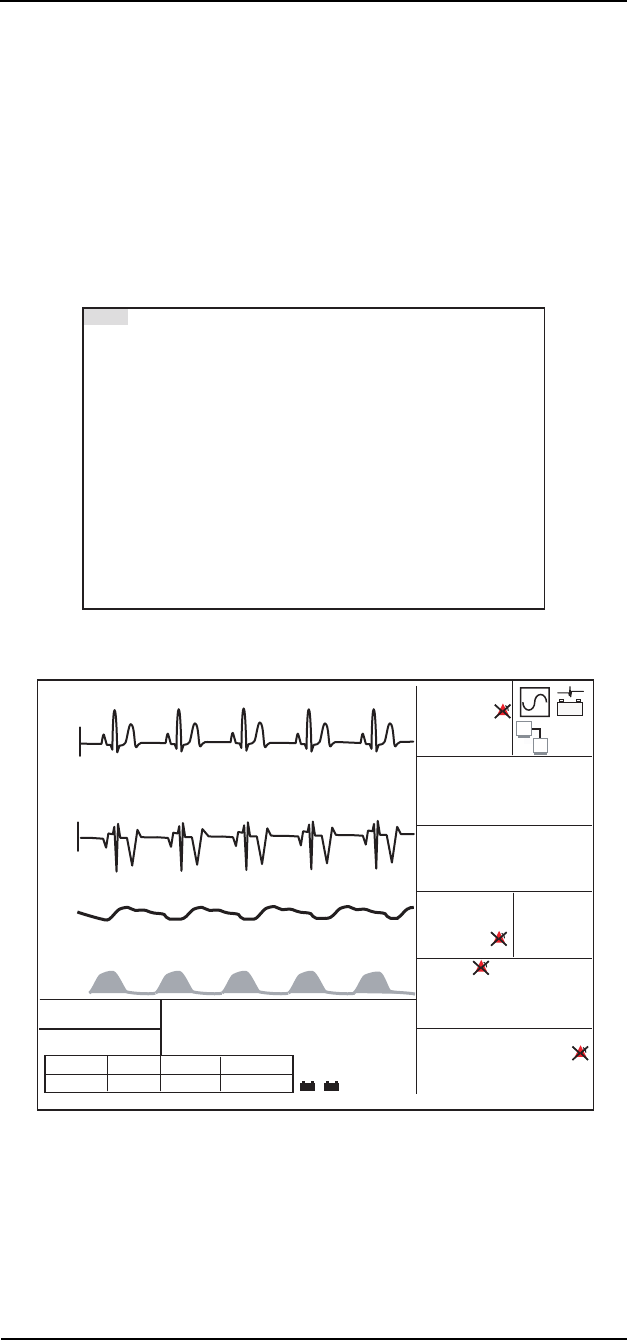
MEDRAD
Veris
8600
2 —28
Double Height Slots
The monitor can display waveforms in three 25mm slots and three
smaller 12.5mm slots.
• Two 25mm slots can be combined to form one 50mm slot.
• Two 12.5mm slots in the, bottom group, can be combined
together to form one 25mm slot.
• No more than two slots can be combined to form a larger
waveform display area
NOTE: Slots 3 and 4 cannot be combined.
Figure 2-18: Display Settings Window with Combined
Slots
Figure 2-19: Double Height Slots
To combine slots to form larger areas to display waveforms set the
lower slot TYPE to OFF. The slot above automatically increases in
size to fill the space.
EXIT TYPE GAIN SWEEP SIZE
MM/S
Waveform 1 ECG II x1.0 25.0 50mm
Waveform 2 OFF x1.0 25.0 25mm
Waveform 3 ECG aVR x1.0 25.0 25mm
Waveform 4 PLETH x1.0 25.0 25mm
Waveform 5 OFF x1.0 25.0 12mm
Waveform 6 ET CO2 x1.0 25.0 12mm
External Display OFF
ALARMS PARAMS DISPLAY
ALARMS PARAMS DISPLAY
Adult
Adult
V000 - NO ADMIT
V000 - NO ADMIT
SPO2: SENSOR
SPO2: SENSOR
ZERO IP1
ZERO IP1
ZERO IP2
ZERO IP2
ADM/DIS CONFIG PRINT
ADM/DIS CONFIG PRINT
SpO2
SpO2
II
II
T1
T1
T2
T2
%
x1
x1
x1
x1
x2
x2
aVR
aVR
CO2
CO2
CO2
CO2
EXP
EXP
INS
INS
INS
INS
INS
INS
1mV
1mV
ECG
ECG
SpO2
SpO2
IBP1 ART
IBP1 ART
mmHg
mmHg
mmHg
mmHg
150 ml/min
150 ml/min
IBP2 CVP
IBP2 CVP
HR
HR
BPM
BPM
RESP Br/m
RESP Br/m
1mV
1mV
60
60
98
98
37
37
8
8
96.4
96.4
97.7
97.7
20
20
13
13
(125)
(125)
145/105
145/105
- +
+
- +
+
CO2
CO2
- +
O2 HAL
O2 HAL
GAS
GAS
N2O
N2O
E
I
17 0.4 39
17 0.4 39
21 2.3 64
21 2.3 64
%
Mixed ENF E 10.5 I 10.0
Mixed ENF E 10.5 I 10.0
MAP
MAP
CYCLE OFF
CYCLE OFF
149/106
149/106
(127)
(127)
NIBP AGE 21:13 min
NIBP AGE 21:13 min
mmHg
mmHg
AUG-16-04 14:12:59
AUG-16-04 14:12:59
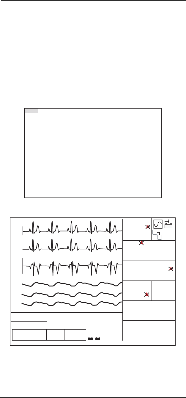
2 —29
2 —Monitor Setup
Each waveform slot displays the parameter or source along the left
edge of the screen. The colors of the waveforms are user selectable
in the PARAMS window. The numerical parameters colors match the
selected waveform color whenever possible.
Cascaded Slots
The monitor can cascade a waveform into the next lower slot and it is
then displayed as twice or three times its original length.
The cascaded data is a continuous band of waveform using the
sweep speed as set in the original waveform slot. The gain and range
settings are the same for the entire cascaded waveform. The
waveform label and scale are not shown for slots where data has
been cascaded from a higher slot.
Figure 2-20: Display Window, Cascaded Slots
Figure 2-21: Cascaded Slots
EXIT TYPE GAIN SWEEP SIZE
MM/S
Waveform 1 ECG II x1.0 25.0 25mm
Waveform 2 Cascade x1.0 25.0 25mm
Waveform 3 ECG aVR x1.0 25.0 25mm
Waveform 4 PLETH x1.0 25.0 12mm
Waveform 5 Cascade x1.0 25.0 12mm
Waveform 6 Cascade x1.0 25.0 12mm
External Display OFF
ALARMS PARAMS DISPLAY
ALARMS PARAMS DISPLAY
Adult
Adult
V000 - NO ADMIT
V000 - NO ADMIT
SPO2: SENSOR
SPO2: SENSOR
ZERO IP1
ZERO IP1
ZERO IP2
ZERO IP2
ADM/DIS CONFIG PRINT
ADM/DIS CONFIG PRINT
SpO2
SpO2
II
II
T1
T1
T2
T2
%
x1
x1
x2
x2
aVR
aVR
CO2
CO2
EXP
EXP
INS
INS
INS
INS
INS
INS
1mV
1mV
ECG
ECG
SpO2
SpO2
IBP1 ART
IBP1 ART
mmHg
mmHg
mmHg
mmHg
150 ml/min
150 ml/min
IBP2 CVP
IBP2 CVP
HR
HR
BPM
BPM
RESP Br/m
RESP Br/m
1mV
1mV
60
60
98
98
37
37
8
8
96.4
96.4
97.7
97.7
20
20
13
13
(125)
(125)
145/105
145/105
- +
+
- +
+
CO2
CO2
- +
O2 HAL
O2 HAL
GAS
GAS
N2O
N2O
E
I
17 0.4 39
17 0.4 39
21 2.3 64
21 2.3 64
%
Mixed ENF E 10.5 I 10.0
Mixed ENF E 10.5 I 10.0
MAP
MAP
CYCLE OFF
CYCLE OFF
149/106
149/106
(127)
(127)
NIBP AGE 21:13 min
NIBP AGE 21:13 min
mmHg
mmHg
AUG-16-04 14:12:59
AUG-16-04 14:12:59

MEDRAD
Veris
8600
2 —30
To cascade a waveform into the next lower slot, set the lower slot
TYPE to CASCADE. The waveform above automatically cascades
into the next lower slot. You can cascade slots 1-2-3, or slots 4-5-6.
NOTE: The display is set up in separate groups of three slots so a
waveform cannot be cascaded from slot 3-4.
Cascade and the double height feature can be applied to the upper
and lower groups of slots independently. It is also not possible to
cascade (double height) waveforms.
Gain and Sweep
The GAIN and SWEEP settings found in the DISPLAY menu can also
be used to modify the way waveforms are displayed on the screen.
The upper three (25mm) slots of the display allow for larger
waveforms to display. Gain settings from the upper set of slots do not
correspond to the gain settings of the lower three slots. In order to
obtain identical waveform sizes in the top and bottom slots, set the
gain of the lower three slots one step higher than the top three slots.
A minimum of four and a half seconds worth of data at a sweep speed
of 25mm per second is displayed. Waveforms can have sweep
speeds of 50, 25, 12.5 or 6.25 mm per second.

2 —31
2 —Monitor Setup
ADM/DIS Softkey (Admit/
Discharge)
Figure 2-22: ADM/DIS Softkey Selected
A patient may be admitted or discharged in the ADM/DIS window,
however it is only necessary to correctly specify the Patient Size
since this adjusts the monitoring defaults.
Figure 2-23: Admit/Discharge Window
NOTE: Patient Size can be also set in the ALARMS window. This is
the same setting and it can be changed in either location.
NOTE: The Unit Label is for future use.
Admitting and
Discharging Patients
• It is recommended that the admit and discharge feature be used
between each patient so that there is a clear break between
patient histories in the memory. This also ensures that label
headers are properly printed out for each patient.
• It is possible to admit a blank patient. If this is done, there is no
patient data label on printed reports. Data from various patients
could appear to merge together onto one trend table or graph.
• It is not necessary to admit a patient for the monitor to function
properly. There is no audible alarm for the “no admit” condition.
A message appears in the informational message box indicating
that no patient has been admitted.
ALARMS PARAMS DISPLAY ZERO IP1
ADM/DIS CONFIG PRINT ZERO IP2
EXIT
Admit NO
Discharge NO
Patient Size Adult
Update NO
Last Name xxxxxxxxxxxx
First Name xxxxxxxxxx
Middle Initial x
Room Number xxxxx
ID Number xxxxxxxxxxxxxxxx
Unit Label 000
CAUTION
!!

MEDRAD
Veris
8600
2 —32
• The discharge feature returns the monitor to the user default
profile last selected. If no user profiles have ever been selected
on a new monitor the CUSTOM DEFAULTS found in the first
position in the defaults window is used.
Adult/Pediatric/Neonatal
(Patient Size)
The monitor is designed to look at the Patient Size information
selected in the ADM/DIS window and determine whether the monitor
should use the Adult, Pediatric, or Neonatal alarm settings while
monitoring.
The patient mode is determined by patient size and is displayed in the
System Status Line.
When Patient Size is changed in the ADM/DIS window, the monitor
determines which window appears when the ALARMS softkey is
selected. By changing Patient Size, the user effectively changes all
the alarm limits for all the monitoring modules. The Patient Size
setting also adjusts the maximum NIBP pressure limit. For Adult and
Pediatric the limit is 300 mmHg. The limit for Neonate is 150 mmHg.
Patient Information
To enter, change, or update patient information:
1. Set the menu to ADM/DIS and press the knob.
2. Go to Patient Size and check that it is correct. Change to Adult,
Pediatric, or Neonate as necessary.
3. Turn the knob to Update and set to YES. Press the knob. The
patient data field can now be selected.
4. Go to the patient name and identity fields. Turn the knob to
select the desired field. Press the knob to go to the blank line.
Turn the knob to select the correct letter.
NOTE: Letters and digits may be entered using the rotary knob.
Two arrow characters also appear among the letters and digits.
Selecting the back arrow allows corrections to be made. The
down arrow skips directly to the next line when finished entering
a line.
5. Fill in the remaining patient information blanks as desired.
6. Select EXIT to return to the main screen. The patient data is
updated on the main screen.
7. Exit the ADM/DIS window and re-enter before attempting to
admit a patient.
CAUTION
!!

2 —33
2 —Monitor Setup
Procedure for
Admitting a Patient
To admit a patient, proceed as follows:
1. Set the menu to ADM/DIS and press the knob. the ADM/DIS
window appears. If the patient data needs to be updated use the
patient information procedure.
2. Rotate the knob to highlight Admit. The admit selection is not
available if a patient has already been admitted.
3. Press the knob to select Admit. Turn the knob to YES. The
message NEW PATIENT is also entered into the trend memory.
NOTE: If there is no patient data a blank patient is admitted.
4. Turn the knob back to EXIT to return to the main screen, or
proceed to update patient information.
Procedure for
Discharging a Patient
To discharge a patient, proceed as follows:
1. Set the menu to ADM/DIS and press the knob. the ADM/DIS
window appears.
2. Rotate the knob to highlight Discharge. The discharge selection
is not available if a patient has not been admitted.
3. Press the knob to select Discharge. Turn the knob to YES.
4. The monitor responds with a confirmation screen.
5. Turn the knob to YES and press to confirm.
6. The monitor clears the patient data fields and returns the
monitor to the last user default profile that was selected.
7. The monitor enters Standby Mode (or Agent Standby Mode if
the monitor has anesthetic options).
NOTE: The monitor enters Standby Mode after a patient is
discharged so that the monitor does not record extraneous data
into the trend memory while sensors and electrodes are
removed from the patient. The message NEW PATIENT is also
entered into the trend memory at the point of discharge.
8. Press the orange STAND BY key to return to the main screen.

MEDRAD
Veris
8600
2 —34
CONFIG Softkey
(System Configuration)
Figure 2-24: CONFIG Softkey Selected
This softkey allows access to the configuration settings. When
activated a configuration settings window appears.
Figure 2-25: System Configuration Window
This window contains settings that are related to the general function
of the overall monitor. The window also has some settings that may
affect physiological monitoring.
• The Alarm Tone Warning and Standby Timeout settings can
permanently disable alarm functions. See “ECG” in Section 5 for
more information on Alarms.
• The Line Frequency setting affects the SpO2 filter function.
• The Return to Factory Defaults setting may make changes
affecting all of the physiological monitoring modules.
The printing and communications settings are discussed in “Printing
and Data Ports” on page 12-1 of this manual. Service mode and
Simulation Mode are described in the
Veris
8600 Service Manual.
ALARMS PARAMS DISPLAY ZERO IP1
ADM/DIS CONFIG PRINT ZERO IP2
Date Format DD-MM-YYYY
Date DAY 10 MONTH JUL YEAR 2004
Time 17:47
Freeze timeout 2 minutes
Standby timeout 30 minutes
Standby tone ON
Alarm tone warning ON
Print Device Internal Printer
Language ENGLISH
Line Frequency 60
Serial Format TEXT Baudrate 38400
Analog Out Select ECG I
Restore Factory Defaults NO
Enter Service Mode NO
Enter Simulation Mode NO
EXIT
CAUTION
!!

2 —35
2 —Monitor Setup
Password Protection
Several settings on the CONFIG and the Enter Network Config
screens are password protected. These are functions that generally
should not be changed during use and their settings should be
adjusted by supervisory personnel, your MEDRAD representative, or
other qualified service personnel. These include; Standby Timeout,
Alarm Tone Warning, Line Frequency, Enter Service Mode, and Enter
Simulation Mode. Contact MEDRAD Service or your local
representative about service passwords.
Date Format
The date format can be set to display or print Day-Month-Year or
Month-Day-Year.
Time/Date Setting
The Time and Date are set in the CONFIG softkey window. Changing
the time and date while monitoring a patient does not affect the
accurate display of patient data, but it clears any recorded trend data.
Freeze Timeout
The FREEZE function can be set to freeze the waveform frame from
30 seconds to five minutes. Choosing OFF causes the FREEZE key
to hold the screen permanently until the FREEZE key is pressed
again. The FREEZE key also captures waveforms that are obscured
by dialog boxes and pop-up windows. When the FREEZE key is
pressed the waveforms are redrawn on the screen. The FREEZE
function forces an exit from the current pop-up window or dialog box.
Standby Timeout
The Standby Timeout can be set to disable the monitor from 5
minutes to 2 hours. Choosing OFF causes the STAND BY key to
disable the monitor permanently until the STAND BY key is pressed
again. This setting is password protected. The factory default value is
30 minutes.
Standby Tone
When set to ON the monitor produces a single low pitched beep
every minute during Standby Mode. When set to OFF there is no tone
to remind the user that the monitor is in Standby Mode.
Alarm Tone Warning
When set to ON the monitor produces a low pitched double beep
every two minutes during the permanent silence condition. When set
to OFF there is no tone to remind the user that the silence condition
is active.
NOTE: Set this safeguard according to your facility protocols and
according to local safety regulations for medical devices.
Print Device
The print device can be set to Internal Printer, Serial, or OFF.
•Set to Internal Printer to print data to the thermal printer on the
optional remote display.
•Set to Serial to print to an external printer or download to a
computer.
•Set to OFF to disable the printing feature.
See “Printing and Data Ports” on page 12-1 for more information.

MEDRAD
Veris
8600
2 —36
Language Settings
The following languages are available in the monitor; ENGLISH,
FRENCH, GERMAN, ITALIAN, SPANISH, JAPANESE, and
PORTUG. (Portuguese).
To change the language:
1. Press the ON/OFF key to start the monitor.
2. Turn the menu knob until the CONFIG softkey is highlighted.
3. Press the menu knob in to select the CONFIG softkey. The
configuration window appears.
4. Turn the knob until the Language setting is highlighted.
5. Press the knob to select the Language setting. The current
language shown to the right is highlighted.
6. Turn the knob until the desired language appears.
7. Press the knob again to select the new language.
8. Exit the configuration window.
The language should be properly set when saving user default
profiles. The correct language can then be restored using only the
DEFAULT key and the default profile dialog box when an unfamiliar
language is set on the monitor.
In situations where the monitor has been left for over 24 hours without
power or charged batteries, the Language setting as well as other
defaults may be lost. In this condition the monitor reverts to the
Language set in the last selected user default profile. ENGLISH is the
default language when no other has been selected.

2 —37
2 —Monitor Setup
PRINT Softkey
Figure 2-26: PRINT Softkey Selected
NOTE: The printer is only found in the remote display. Printer settings
may be adjusted from the main monitor or the remote display.
The PRINT softkey allows access to the printer settings window.
Figure 2-27: Print Configuration Window
If the internal thermal printer does not respond, check the CONFIG
menu. The Printer Device must be set to Internal Printer. If the
monitor returns to factory defaults the CONFIG setting returns to
Serial.
The setting Alarm Print causes the monitor to print all parameters
upon the activation of a new high or medium level alarm.
See “Printing and Data Ports” on page 12-1 for more information on
printing.
TABULAR PRINTING
Numerical values for all current parameters are printed.
GRAPHICAL PRINTING
If both Waveform 1 and 2 have been set to a physical parameter the
print out is a split dual waveform. If only one of the waveforms is
turned on, a single waveform is printed using the entire waveform
area. If both waveforms are turned off, the waveform area of the print
out is blank.
ALARMS PARAMS DISPLAY ZERO IP1
ADM/DIS CONFIG PRINT ZERO IP2
EXIT
Print Type Graphical
Alarm Print OFF
BP Print OFF
Interval Print OFF
INTERVAL PRINT TYPE TABULAR
Snapshot Size 6 Seconds
History Size 6 Seconds
Waveform 1 ECG II
Gain x1.0
Waveform 2 Pleth
Gain x1.0
Printer Speed 25 mm/sec

MEDRAD
Veris
8600
2 —38
Default Settings
Factory Defaults
ALARMS SETTINGS
Alarm Type Range Adult Pediatric Neonate
Alarm Volume 1-10 5 5 5
ECG lead fail high, medium, low medium medium medium
Heart Rate High 80-250, Off 150 150 180
Heart Rate Low 20-160, Off 40 40 90
SpO
2
High 70-98, Off Off Off Off
SpO
2
Low 1-98, Off 90 90 90
NIBP Systolic High 75-240, Off 200 200 140
NIBP Systolic Low 50-150, Off 50 50 35
NIBP Diastolic High 50-180, Off 100 100 80
NIBP Diastolic Low 15-50, Off 30 30 30
NIBP Mean High 70-200, Off 150 150 100
NIBP Mean Low 25-125, Off 50 50 35
Temperature 1 High 68.0-111.0°F, Off 100.0°F 100.0°F 100.0°F *
Temperature 1 Low 68.0-111.0°F, Off 93.0°F 93.0°F 93.0°F *
Temperature 2 High 68.0-111.0°F, Off 100.0°F 100.0°F 100.0°F *
Temperature 2 Low 68.0-111.0°F, Off 93.0°F 93.0°F 93.0°F *
Respiration High 6-120, Off 36 36 60 *
Respiration Low 6-120, Off 4 4 14 *
CO
2
Inspired High 0-100 mmHg, Off 10 mmHg 10 mmHg 10 mmHg *
CO
2
Inspired Low 0-100 mmHg, Off 5 mmHg 5 mmHg 5 mmHg *
CO
2
Expired High 0-100 mmHg, Off 55 mmHg 55 mmHg 55 mmHg *
CO
2
Expired Low 0-100 mmHg, Off 20 mmHg 20 mmHg 20 mmHg *
O
2
Inspired High 18-100%, Off 100 100 100 *
O
2
Inspired Low 18-100% 18 18 18 *
O
2
Expired High 18-100%, Off 100 100 100 *
O
2
Expired Low 18-100%, Off Off Off Off *
Apnea 5-60, Off 20 20 20 *
IBP1 Systolic High 0 to 240, Off 200 200 140 *
IBP1 Systolic Low 0 to 240, Off 50 50 50 *
IBP1 Diastolic High 0 to 240, Off 100 100 80 *
IBP1 Diastolic Low 0 to 240, Off 30 30 30 *
IBP1 Mean High -10 to 240, Off 150 150 100 *
IBP1 Mean Low -10 to 240, Off 50 50 40 *
IBP2 Systolic High 0 to 240, Off *
IBP2 Systolic Low 0 to 240, Off *
IBP2 Diastolic High 0 to 240, Off *
IBP2 Diastolic Low 0 to 240, Off *
IBP2 Mean High -10 to 240, Off 15 15 15 *
IBP2 Mean Low -10 to 240, Off 1 1 1 *
* Only on units with these parameters.

2 —39
2 —Monitor Setup
Alarm Type Range Adult Pediatric Neonate
ART Systolic High 0 to 240, Off 200 200 140 *
ART Systolic Low 0 to 240, Off 50 50 50 *
ART Diastolic High 0 to 240, Off 100 100 80 *
ART Diastolic Low 0 to 240, Off 30 30 30 *
ART Mean High -10 to 240, Off 150 150 100 *
ART Mean Low -10 to 240, Off 50 50 40 *
PA Systolic High 0 to 240, Off 40 40 40 *
PA Systolic Low 0 to 240, Off 15 15 15 *
PA Diastolic High 0 to 240, Off 15 15 15 *
PA Diastolic Low 0 to 240, Off 5 5 5 *
PA Mean High -10 to 240, Off 20 20 20 *
PA Mean Low -10 to 240, Off 10 10 10 *
LA Mean High -10 to 240, Off 15 15 15 *
LA Mean Low -10 to 240, Off 1 1 1 *
LV Systolic High 0 to 240, Off 200 0 0 *
LV Systolic Low 0 to 240, Off 60 0 0 *
LV Diastolic High 0 to 240, Off 40 0 0 *
LV Diastolic Low 0 to 240, Off 0 0 0 *
LV Mean High -10 to 240, Off 120 0 0 *
LV Mean Low -10 to 240, Off 60 0 0 *
RA Mean High -10 to 240, Off 15 15 15 *
RA Mean Low -10 to 240, Off 1 1 1 *
RV Systolic High 0 to 240, Off 50 0 0 *
RV Systolic Low 0 to 240, Off 20 0 0 *
RV Diastolic High 0 to 240, Off 20 0 0 *
RV Diastolic Low 0 to 240, Off 0 0 0 *
RV Mean High -10 to 240, Off 30 0 0 *
RV Mean Low -10 to 240, Off 10 0 0 *
CVP Mean High -10 to 240, Off 15 15 15 *
CVP Mean Low -10 to 240, Off 1 1 1 *
ICP Mean High -10 to 240, Off 15 15 15 *
ICP Mean Low -10 to 240, Off 1 1 1 *
Primary InspiredHigh 0.1-20.0%, Off 2.3 2.3 2.3 *
Primary InspiredLow 0.0-10.0%, Off OFF OFF 1.5 *
Primary ExpiredHigh 0.1-20.0%, Off 1.5 1.5 1.5 *
Primary ExpiredLow 0.0-10.0%, Off OFF 1.5 OFF *
N
2
O Inspired High 20-100%, Off 75 75 75 *
N
2
O Inspired Low 1-50%, Off OFF OFF OFF *
N
2
O Expired High 20-100%, Off OFF OFF OFF *
N
2
O Expired Low 1-50%, Off OFF OFF OFF *
* Only on units with these parameters.

MEDRAD
Veris
8600
2 —40
Alarm Type Range Adult Pediatric Neonate
HAL Inspired High 0.1-20.0%, Off 2.3 2.3 2.3 *
HAL Inspired Low 0.0-10.0%, Off OFF OFF OFF *
HAL Expired High 0.1-20.0%, Off 1.5 1.5 1.5 *
HAL Expired Low 0.0-10.0%, Off OFF OFF OFF *
ENF Inspired High 0.1-20.0%, Off 4.8 4.8 4.8 *
ENF Inspired Low 0.0-10.0%, Off OFF OFF OFF *
ENF Expired High 0.1-20.0%, Off 3.2 3.2 3.2 *
ENF Expired Low 0.0-10.0%, Off OFF OFF OFF *
ISO Inspired High 0.1-20.0%, Off 3.6 3.6 3.6 *
ISO Inspired Low 0.0-10.0%, Off OFF OFF OFF *
ISO Expired High 0.1-20.0%, Off 2.4 2.4 2.4 *
ISO Expired Low 0.0-10.0%, Off OFF OFF OFF *
DES Inspired High 0.1-20.0%, Off 18.0 18.0 18.0 *
DES Inspired Low 0.0-10.0%, Off OFF OFF OFF *
DES Expired High 0.1-20.0%, Off 12.0 12.0 12.0 *
DES Expired Low 0.0-10.0%, Off OFF OFF OFF *
SEV Inspired High 0.1-20.0%, Off 5.1 5.1 5.1 *
SEV Inspired Low 0.0-10.0%, Off OFF OFF OFF *
SEV Expired High 0.1-20.0%, Off 3.4 3.4 3.4 *
SEV Expired Low 0.0-10.0%, Off OFF OFF OFF *
* Only on units with these parameters.

2 —41
2 —Monitor Setup
MONITORING PARAMETERS
Parameter Selectable Options Factory Default
HR Source Smart, ECG, IBP, SPO2, NIBP Smart
Gating Off, ECG Wave, SpO
2
Wave, Off *
ECG Pulse, SpO
2
Pulse
ECG On, Off On
ECG Cable 5 Lead, 3 Lead 3 Lead (Base, BasePlus)
5 Lead (Other models)
ECG Filter Monitor Monitor
Sensitivity High, Medium, Low Medium
Auto lead switching Yes, No Yes
IBP 1 Site ART, PA, LA, RA, LV, RV,
CVP, ICP, OFF ART *
IBP 1 Range -10 to 10, 0 to 20, 0 to 30, 0 to 40,
0 to 60, 0 to 100, 0 to 150, 0 to 200,
0 to 300, and Auto-ranging 0 to 200 *
IBP 1 Zero None, One, All None *
IBP 2 Site ART, PA, LA, RA, LV, RV,
CVP, ICP, OFF CVP *
IBP 2 Range -10 to 10, 0 to 20, 0 to 30, 0 to 40,
0 to 60, 0 to 100, 0 to 150, 0 to 200,
0 to 300, and Auto-ranging 0 to 20 *
IBP 2 Zero None, One, All None *
NIBP On, Off On
NIBP Tone End, None None
Heart Rate
Tone Volume 1-10, Off 5
SpO
2
On, Off On
SpO
2
Average 3, 6, 9,12,15,18, 21 12
SpO
2
Search Time 10, 20, 30, 40 20
SpO
2
Low
Limit Alarm High, Medium High
Respiration On, Off On
Temperature 1 On, Off On *
Temperature 2 On, Off On *
Unit of measure °F, °C °F *
CO
2
Unit of measure Percent, mmHg, KPa, Torr mmHg *
Agent to Monitor Halothane, Enflurane, Isoflurane, Automatic *
(Primary) Desflurane, Sevoflurane, Automatic
Gas Flow Rate 100, 150, 200 mL 200 mL *
Flow Mode Exhaust Exhaust *
* Only on units with these parameters.

MEDRAD
Veris
8600
2 —42
CONFIGURATION SETTINGS
Configuration Selectable Options Factory Default
Date Format DD-MM-YYYY; MM-DD-YYYY DD-MM-YYYY
Date Day, Month, Year (Not Applicable)
Time Hour, Minute (Not Applicable)
Freeze Timeout 30 seconds, 1, 2, 3, 4, 5 minutes, Off 2 min
Standby Timeout 5, 10, 15, 30, 45 minutes, 1, 2 hrs, Off 30 min
Standby Tone On, Off On
Alarm Tone Warning On, Off On
Printer Device Serial, Internal Printer, Off Internal Printer
(w/remote)
Serial (w/o remote)
Language English, French, German, Italian,
Spanish, Portuguese, Japanese English
Line Frequency 50, 60 Hz (By Destination)
Serial Format TEXT, CSV, CUSP CUSP
Baud Rate 2400, 4800, 9600, 19200, 38400,
57600, Hi Speed Hi Speed
Analog Out Select ECG I, II, III, aVR, aVL, aVF, V;
Resp, Pleth, IBP 1, IBP 2, EtCO
2
,
O
2
, Agent, Off ECG I
Restore Factory Defaults Yes, No No
Enter Service Mode Yes, No No
Enter Simulation Mode Yes, No (password protected) No
Enter Network
Configuration Yes, No (password protected) No
NETWORK CONFIGURATION SETTINGS
Sync Type Serial, Fiber Optic, Fiber-Wireless,
Wireless Serial
IP Address nnn.nnn.nnn.nnn Set at factory
Netmask nnn.nnn.nnn.nnn Set at factory
Port nnnnn Set at factory
Connect Type Peer-to-Peer, Access Point Peer-to-Peer
Channel 1-14 10
SSID 16 characters Set at factory
* Only on units with these parameters.

2 —43
2 —Monitor Setup
PRINTER SETTINGS
Setting Selectable Options Factory Default
Print Type (Demand) Graphical, Tabular Graphical
Alarm Print Off, Graphical, Tabular Off
BP Print Off, Graphical, Tabular Off
Interval Print Off, 1, 2, 5, 10, 15, 30, 60 minutes
2, 4, 8,12, 24 hours Off
(1, 2, 5, 10, 15, 20, 30 seconds only
if
Printer Device
is set to
Serial
)
Interval Print Type Graphical, Tabular Tabular
Snapshot Size 6,12,18, 24 seconds 6 seconds
History Size 6,12 seconds 6 seconds
Waveform 1 ECG I, II, III, V, aVR, aVL, aVF,
PLETH, IBP 1, IBP 2, EtCO
2
, O
2
,
Agent, N
2
O, Off ECG II
Gain (waveform 1) x0.5, x1.0, x2.0, x4.0 x1.0
Waveform 2 ECG I, II, III, V, aVR, aVL, aVF,
PLETH, IBP 1, IBP 2, EtCO
2
, O
2
,
Agent, N
2
O, Off PLETH
Gain (waveform 2) x0.5, x1.0, x2.0, x4.0 x1.0
Printer Speed 12.5, 25.0, 50.0 mm/sec 25.0 mm/sec
DISPLAY SETTINGS
Setting Selectable Options Factory Default
Waveform 1:
Type: Lead I, Lead II, Lead III, Lead V,
Lead avL, Lead avR, Lead avF, and
Off ECG II
Gain: 0.5x, 1x, 2x, or 4x 1x
Sweep: 6.25, 12.5, 25, or 50 mm per second 25 mm per second
Size: 25 or 50 mm 50 mm
Waveform 2:
Type: Lead I, Lead II, Lead III, Lead V,
Lead avL, Lead avR, Lead avF,
Pleth, IBP 1, IBP 2, EtCO
2
, O
2
,
Primary Halogenated Agent, N
2
O,
Breath by Breath, Cascade, and Off Off
Gain: 0.5x, 1x, 2x, or 4x 1x
Sweep: 6.25, 12.5, 25, or 50 mm per second 25 mm per second
Size: 25 or 50 mm 25 mm

MEDRAD
Veris
8600
2 —44
Setting Selectable Options Factory Default
Waveform 3:
Type: Lead I, Lead II, Lead III, Lead V,
Lead avL, Lead avR, Lead avF,
Pleth, IBP 1, IBP 2, EtCO
2
, O
2
,
Primary Halogenated Agent, N
2
O,
Breath by Breath, Cascade, and Off ECG I
Gain: 0.5x, 1x, 2x, or 4x 1x
Sweep: 6.25, 12.5, 25, or 50 mm per second 25 mm per second
Size: 25 mm 25 mm
Waveform 4:
Type: Lead I, Lead II, Lead III, Lead V,
Lead avL, Lead avR, Lead avF,
Pleth, IBP 1, IBP 2, EtCO
2
, O
2
,
Primary Halogenated Agent, N
2
O,
Breath by Breath, and Off PLETH
Gain: 0.5x, 1x, 2x, or 4x 1x
Sweep: 6.25, 12.5, 25, or 50 mm per second 25 mm per second
Size: 12 or 25 mm 12 mm
Waveform 5:
Type: Lead I, Lead II, Lead III, Lead V,
Lead avL, Lead avR, Lead avF,
Pleth, IBP 1, IBP 2, EtCO
2
, O
2
,
Primary Halogenated Agent, N
2
O,
Breath by Breath, Cascade, and Off aVL
Gain: 0.5x, 1x, 2x, or 4x 1x
Sweep: 6.25, 12.5, 25, or 50 mm per second 25 mm per second
Size: 12 or 25 mm 12 mm
Waveform 6:
Type: Lead I, Lead II, Lead III, Lead V,
Lead avL, Lead avR, Lead avF,
Pleth, IBP 1, IBP 2, EtCO
2
, O
2
,
Primary Halogenated Agent, N
2
O,
Breath by Breath, Cascade, and Off aVR
Gain: 0.5x, 1x, 2x, or 4x 1x
Sweep: 6.25, 12.5, 25, or 50 mm per second 25 mm per second
Size: 12 or 25 mm 12 mm

3 —1
3 — Alarms and Messages
Alarm Description
The
Veris
monitor provides both audible and visible alarm indicators
to alert the operator of system status changes and physiological
parameter alarms.
Alarms are provided for all monitored parameters. Each parameter
limit alarm condition triggers both audible and visible alarms until one
of the following events occurs:
• The parameter value returns to within the alarm limit.
• The alarm limit is set beyond the present parameter value.
• The SILENCE key is pressed. (Audible alarms only)
• The monitor is placed in Standby Mode.
NOTE: The Alarm Limits menu only displays the parameters present
in the configuration.
Remote Display Alarms
The alarms that appear and sound on the patient monitor also appear
and sound on the optional remote display. The delay time for the
alarm from the patient monitor to the remote display is less than 1
second. Alarms can be silenced or turned off from the remote display
as if they were silenced or turned off at the patient monitor.
Audible Alarms
All alarms conform to EN 475 requirements. Informational messages
and system alerts do not have an audible alarm component.
HIGH PRIORITY ALARMS
The high priority alarm consists of a pair of audible bursts. Each burst
consists of 5 tone pulses. The pair of bursts repeat every eight
seconds. For each burst there is a short delay between the third and
fourth pulse. The frequency of each pulse is 1000 Hz.
MEDIUM PRIORITY ALARMS
Each medium priority alarm consists of an audible burst of three
pulses repeated approximately every 25 seconds. The frequency of
each pulse is 800 Hz.
LOW PRIORITY ALARMS
Each low priority alarm consists of an audible burst of two pulses
repeated approximately every 15 seconds. The frequency of each
pulse is 350 Hz.
ADVISORY ALERTS
Each advisory alert consists of an audible burst of two pulses
repeated approximately every 5 minutes. The frequency of each
pulse is 300 Hz.
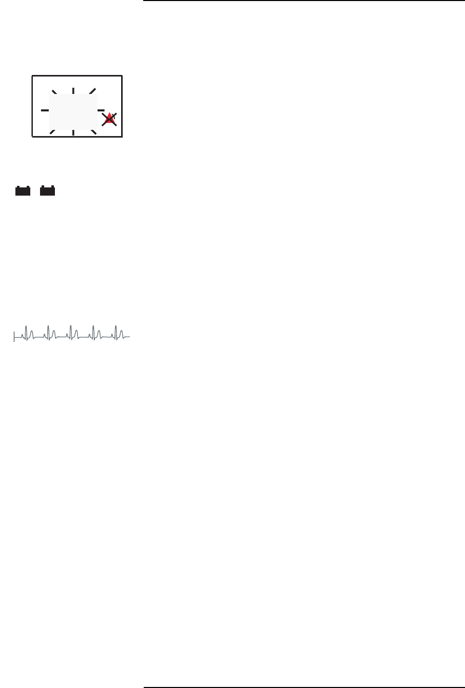
MEDRAD
Veris
8600
3 —2
Visible Alarms
In addition to audible alarms, visual text and symbol alarms are
displayed on the screen. Each message or symbol is specific to its
respective parameter or condition.
FLASHING NUMERICAL PARAMETERS
If a physiological parameter exceeds a high limit or falls below a low
limit value, the numerical value displayed flashes. This function
cannot be suspended and is visible when pop-up menus are
activated.
ALARM MESSAGE LINES
There is space for two text lines provided directly below the NIBP box.
If multiple alarms are active, they alternate in the alarm area. The
bottom line is used for the informational messages and advisory
alerts.
Low level alarms and informational level messages are displayed in
this area for the vital signs that have a waveform displayed. For
parameters that do not have a waveforms displayed, all level of
alarms are reported in the Alarm Message Lines.
Informational, low, and medium level alarm text messages appear in
yellow and high alarm warning messages appear in red.
WAVEFORM SLOT VISUAL ALARMS
When a high or medium alarm occurs for a vital sign that has an
active waveform, the message appears in the top center of the
waveform traces in large text. If there are multiple alerts to be
displayed in a waveform slot, the messages alternate.
If the waveform exists in multiple slots, either through cascade or
duplicate waveforms from alternate leads, the waveform messages
only occur in the top most slot.
Waveform Slot Alarms are not visible during the following conditions.
• The waveform is not selected to be displayed.
• A pop-up window or menu covers the waveform slot.
If a high or medium level alarm message cannot be displayed in the
waveform slot due to a pop-up window, the alarm message displays
in the Alarm Message Lines near the bottom of the screen.
Waveforms Frozen
If a waveform is “frozen” and data is still being acquired, high and
medium alarm messages appear based on the real-time data being
acquired, not the “frozen” waveform.
%
SpO2
SpO2
98
98
Adult
Adult
V000 - NO ADMIT
V000 - NO ADMIT
SPO2: SENSOR
SPO2: SENSOR
- +
+
- +
+
II
II
x1
x1
1mV
1mV
HIGH PULSE RATE

3 —3
3 —Alarms and Messages
Alert Icons
There are three alert icons that may appear on the main screen.
SUSPENDED ALARM ICONS
The alarm inhibit icon appears in the parameter boxes when an
individual parameter’s alarms are turned OFF.
When a red bell icon appears in the top waveform slot, all the
monitor’s audible alarms have been silenced. The duration of the
silence condition appears to the right of the bell icon.
2 Min = 2 minutes
= permanent
Visual alarms continue to be displayed as described.
BATTERY ICONS
Battery icons appear in the System Status Line indicating battery
status when AC (Mains) power is not available and battery charging
status when AC (Mains) is connected. The batteries change color
depending on their charge status. A battery icon with a cardiac
waveform also appears in the Heart Rate parameter box to indicate
the status of the ECG module battery. See “Battery Indicators” on
page 2-2 for more information about battery status and charging.
Special Alarm Conditions
The monitor’s alarms may be adjusted to suit the specific needs of
the clinical environment. Special functions are included for the benefit
of the user, so that “nuisance alarms” during patient setup do not
become distracting to the caregiver. Alarm Silence and Standby
Mode are available for this purpose. There are additional safeguards
included to protect against the misuse of these functions.
Alarms at Start Up
Audible alarms do not occur until the first valid measurement has
occurred for that parameter. Visual messages and alarms are present
immediately when a module is activated.
Alarm Silence
A SILENCE key is provided on the front panel of the monitor.
SILENCE 2 MINUTES
Pressing this key momentarily begins a two minute alarm silence.
The alarm icon appears in the System status Line followed by the
message 2 Min in white text.
New high and medium level alarms end the two minute silence when
the alarm condition occurs.
Pressing the SILENCE key a second time ends the silence condition
and normal alarms resume.
∞

MEDRAD
Veris
8600
3 —4
PERMANENT SILENCE
• All alarms are silenced, including those at higher levels, until the
permanent silence is ended.
Press and hold the SILENCE key to permanently silence the alarms.
The alarm icon appears in the System Status Line followed by an
infinity symbol. Notice that the long key-press tone occurs after
holding the key in for two seconds, confirming that permanent silence
was selected.
Pressing the SILENCE key a second time ends the silence condition
and normal alarms resume.
Alarms tone warning
(Warning Tone)
During a permanent alarm silence condition, and when this safeguard
is activated, an Alarms tone warning (Warning Tone) occurs when a
new high or medium level alarm is generated. The tone is a low
pitched double beep the same as the long key press tone.
A password is required to turn this function off. The Alarms tone
warning function can be set in the CONFIG menu.
Alarm Volume
The alarm volume can be set to levels 1 to 10 with 10 being the
loudest. This can be set in the ALARMS menu.
The alarm volume cannot be set to OFF. To permanently silence the
monitor press and hold the SILENCE key.
NOTE: This function does not change the volume of the audible heart
rate. The pulse tone volume is adjusted separately in the PARAMS
menu.
NOTE: The Alarm Limits menu only displays the parameters present
in the configuration.
Minimum Volume Auto-Reset
When the monitor is powered on, the last alarm volume setting
resumes, except when the previous volume setting was 1. In this case
the monitor returns with a volume setting of 2. This function cannot be
disabled.
CAUTION
!!

3 —5
3 —Alarms and Messages
Standby Mode
This is a function on Base, Base Plus, and all Cardiology systems.
This function may be set in the CONFIG menu. It is not password
protected. All functions and alarms are suspended in Standby Mode.
The screen appears blank and the message STANDBY MODE
displays in large red characters.
If the Standby Tone is set to ON, The monitor beeps once every
minute when in Standby Mode. There is a single low pitched beep to
alert the user that the monitor has been left in Standby Mode.
Agent Standby Mode
This is a function on all Anesthesiology systems. The
AGENT STANDBY
MODE
message appears in the top waveform slot in large red letters.
The symbol for permanent alarm silence also appears at the top of
the display.
The SILENCE key is not active during Agent Standby Mode. All
audible alarms are suspended until the STAND BY key is pressed.
The Agent Standby Mode is provided so that the
Veris
monitor can be
set up and checked with an anesthetic delivery system prior to clinical
use without generating distracting alarms.
Perform any preparatory procedures as required by your hospital’s
protocols.
Press the STAND BY key to begin patient monitoring. The standby
message disappears and normal alarms resume. The SILENCE key
also returns to normal operation.
Standby Mode Timeout
This is a function on Base, Base Plus, and all Cardiology systems
and affects the Standby Mode. The Standby Mode Timeout can be
set in the CONFIG softkey menu. The monitor automatically returns
to monitoring within a specified amount of time. The range can be set
from 5 minutes to 2 hours, or OFF. A password is required to change
the setting for this safeguard.
SpO
2
Low Limit Auto-Reset
If the SpO2 alarm limit level is set below 85%, the monitor
automatically returns to the value 90% each time the monitor is
turned on. If the CUSTOM DEFAULTS are set with an SpO2 low limit
value above 85%, the monitor automatically returns to the higher
value each time the monitor is turned on. This function cannot be
disabled.
SpO
2
Low Limit Off Alarm
There is an alarm message generated if the SpO2
Low Limit is set to
OFF. The message LOW SAT OFF appears in yellow text in the Alarm
Message Lines. This alarm message continues to display regardless
of the SpO2 module being set to on or off in the PARAMS menu.
The monitor also displays the alarm alarm inhibit icon in the lower
right corner of the SpO2 numerical display box. The red alarm inhibit
icon is normally displayed when any SpO2 limit is turned off.

MEDRAD
Veris
8600
3 —6
Triggering an Alarm
A patient alarm is activated only when the value of one of the
patient's parameters exceeds one of the alarm limits. For example, if
the high saturation limit is set to 97%, the
Veris
monitor sounds an alarm
when the patient’s SpO2 reaches 98%. It will not alarm at 97%.
Similarly, if the low saturation limit is set to 90%, the alarm sounds
when the patient's SpO2 falls to 89% or below.
• To trigger an alarm, the patient's value must exceed the
parameter's limit.
Alarms Testing
To check and ensure that the audible and visual alarm limit settings
are operating as expected, the user may do so by performing the
following suggested procedure:
1. Apply power to the monitor. Observe that all displays and LEDs
illuminate.
2. Place the SpO2 probe on your finger. Allow readings to stabilize.
3. Observe the pulse rate that is being displayed and adjust the
low pulse rate limit to a value greater than the observed pulse
rate value.
4. Verify that the low pulse rate violation message is displayed on
the LCD message bar and that the alarm tone sounds.
5. Once verified, return the low pulse rate or SpO2 waveform limit
to the previously set value, or to one that is required for the
patient to be monitored.
WARNING
!!

3 —7
3 —Alarms and Messages
Alarm Message List
Included here is a list of messages, alerts, and alarms that may
appear in the waveform slots or in the system message lines of the
display.
Shared Source Alarms
Alarms and messages for heart rate may be generated by more than
one parameter.
Priority Description
LOW PULSE RATE High The heart rate value has dropped below the value set
in the ALARMS menu. This can be generated from
the ECG, IBP, SpO2, or the NIBP module.
HIGH PULSE RATE High The heart rate value has exceeded the value set in
the ALARMS menu. This can be generated from the
ECG, IBP, SpO2, or the NIBP module.
ECG Alarms
Priority Description
ECG:LOST High The ECG amplitude is too low. Check electrodes,
lead wires, and cables. If necessary, change to a
different lead.
ECG:LA LEAD OFF User Selectable The left arm lead is off. Reconnect the lead.
ECG:LL LEAD OFF User Selectable The left leg lead is off. Reconnect the lead.
ECG: V LEAD OFF User Selectable The chest lead is off. Reconnect the lead.
ECG:LEADS OFF User Selectable The ECG leads are off. Either the right leg is off or
there is more than one lead off. Check the lead(s).
SpO
2
Alarms
Priority Description
SpO2: ERROR Low The monitor has detected a fault with the SpO2
function. Contact MEDRAD Service or your local
representative.
SpO2:SENSOR Low The SpO2 sensor is not properly positioned.
SpO2:HIGH AMBIENT Low The SpO2 module is reading excessive light. Shield
the sensor or reduce the amount of ambient light.
SpO2:SEARCH Low The module cannot find a pulse in SpO2 signal.
SpO2:SIGNAL Low The SpO2 signal is too weak to measure. Check
sensor site for low perfusion and reposition sensor if
necessary.
SpO2:LOST Medium The monitor is receiving no SpO2 signal. Check
sensor site for low perfusion and reposition sensor if
necessary.
SpO2:NO SENSOR Low The SpO2 sensor or extension cable is missing or
defective. Connect or replace the sensor or the
extension cable.

MEDRAD
Veris
8600
3 —8
Priority Description
LOW SpO2High/Medium The SpO2 value has dropped below the value set in
the ALARMS menu. This alarm can be set to high or
medium priority in the PARAMS menu.
HIGH SpO2Medium The SpO2 value has exceeded the value set in the
ALARMS menu.
LOW SAT OFF Informational The SpO2 low limit has been set to OFF in the
ALARMS menu.
Temperature Alarms
Priority Description
TEMP1: NO PROBE Low Probe is not present for temperature channel 1.
TEMP1:BAD PROBE Low Temperature probe for temperature channel 1 is
defective.
TEMP1: NOT READY Low Set-up period for temperature channel 1
TEMP1:ERROR Low The monitor has detected a fault with the temperature
module for temperature channel 1. Contact the
MEDRAD Service Department.
LOW TEMP1 Medium Temperature value for temperature channel 1
dropped below the value set in the ALARMS menu.
HIGH TEMP1 Medium The temperature value for temperature channel 1 has
exceeded the value set in the ALARMS menu.
TEMP2: NO PROBE Low Probe is not present for temperature channel 2.
TEMP2:BAD PROBE Low Temperature probe for temperature channel 2 is
defective.
TEMP2: NOT READY Low Set-up period for temperature channel 2
TEMP2:ERROR Low The monitor has detected a fault with the temperature
module for temperature channel 2. Contact the
MEDRAD Service Department.
LOW TEMP2 Medium Temperature value for temperature channel 2
dropped below the value set in the ALARMS menu.
HIGH TEMP2 Medium The temperature value for temperature channel 2 has
exceeded the value set in the ALARMS menu.

3 —9
3 —Alarms and Messages
NIBP Alarms
Priority Description
BP: SYS HIGH Medium The systolic value has exceeded the value set in the
ALARMS menu.
BP: SYS LOW Medium The systolic value has dropped below the value set in
the ALARMS menu.
BP: DIA HIGH Medium The diastolic value has exceeded the value set in the
ALARMS menu.
BP: DIA LOW Medium The diastolic value has dropped below the value set
in the ALARMS menu.
BP: MAP HIGH Medium The mean arterial pressure value has exceeded the
value set in the ALARMS menu.
BP: MAP LOW Medium The mean arterial pressure value has dropped below
the value set in the ALARMS menu.
BP: CALIB ERROR Low The monitor had detected a fault with the calibration.
Cycle the power to the monitor. If the problem
persists, contact MEDRAD Service or your local
representative.
BP: CHECK CUFF Low Displayed when a neonatal cuff is used while the
monitor is in the adult or pediatric mode. Switch to
neonatal mode when using a neonatal cuff. Can also
indicate a leak in the cuff, or the cuff is wrapped too
loosely.
BP: EXCES MOTION Low Patient motion or shivering is interfering with an
accurate reading.
BP: LO PULSE AMP Low Pulse amplitude is too low. Reposition cuff.
BP: NO DEFLATE Low The monitor was unable to deflate the NIBP cuff.
Disconnect the cuff and contact MEDRAD Service or
your local representative.
BP: MAX TIME Low Maximum time (2 minutes) allowed for measuring the
blood pressure has been exceeded. Repeat
measurement.
BP: MAX PRESSURE Low Maximum allowed cuff pressure (300 mmHg adult or
150 mmHg neonatal) has been attained.
BP: PLEASE WAIT Informational The cuff has not completely deflated. Wait for
deflation and then press NIBP key again.
BP: ERROR Low The monitor has detected a fault with the NIBP
function. Contact MEDRAD Service or your local
representative.
BP: NOISE Low The monitor was unable to take a blood pressure
reading due to noise on the NIBP signal. Keep the
patient still while the NIBP reading is being taken.
BP: NOT TAKEN Low The monitor was unable to take a blood pressure
reading. Check cuff position.

MEDRAD
Veris
8600
3 —10
IBP Alarms
Priority Description
HR LOST High The heart rate value has dropped below the
detectable limit for the channel. Verify that the correct
site has been selected for the channel. This message
is only generated for channels set to ART or PA sites.
HIGH SYS Medium The systolic value has exceeded the value set in the
ALARMS menu.
LOW SYS Medium The systolic value has dropped below the value set in
the ALARMS menu.
HIGH DIA Medium The diastolic value has exceeded the value set in the
ALARMS menu.
LOW DIA Medium The diastolic value has dropped below the value set
in the ALARMS menu.
HIGH MAP Medium The mean arterial pressure value has exceeded the
value set in the ALARMS menu.
LOW MAP Medium The mean arterial pressure value has dropped below
the value set in the ALARMS menu.
OFF SCALE Informational The IBP value has exceeded the scale for the
channel, and the waveform has been clipped. Adjust
the range to display the entire waveform.
NO XDUCER Informational Transducer is not connected to the channel. Check
cable connections and verify that the correct
transducer is being used.
BAD XDUCER Informational An incorrect or damaged transducer is connected to
the channel. Specified transducers must have an
impedance greater than 300 ohms.
FACT CAL Medium There is an error in the factory calibration memory.
IBP monitoring is suspended until corrected. Contact
MEDRAD Service or your local representative.
ZERO GOOD Informational The IBP zero calibration for the channel was
successful. The zero pressure point has been
adjusted to the current ambient room pressure.
ZERO FAIL Informational The zero calibration was unsuccessful. Calibration
was aborted due to detection of beat or pressure
fluctuations. Contact MEDRAD Service or your local
representative if the monitor continues to fail
calibration.
NOT ZEROED Informational The transducer needs to be zeroed. Calibrate the
monitor with the transducer.
NOTE: IBP alarms are preceded by the specific site and channel
number such as ART1:NO XDUCER.

3 —11
3 —Alarms and Messages
Capnometry (CO
2
)
Alarms and Messages
Priority Description
LOW EtCO2Medium The end-tidal CO2 value has dropped below the value
set in the ALARMS menu.
HIGH EtCO2Medium The end-tidal CO2 value has exceeded the value set
in the ALARMS menu.
LOW INCO2Medium The inspired CO2 value has dropped below the value
set in the ALARMS menu.
HIGH INCO2Medium The inspired CO2 value has exceeded the value set
in the ALARMS menu.
LOW RESP Medium The respiration value has dropped below the value
set in the ALARMS menu. This is generated from the
capnography module.
HIGH RESP Medium The respiration value has exceeded the value set in
the ALARMS menu. This is generated from the
capnography module.
Agent Gas
Alarms and Messages
Priority Description
AGT:NO BREATH High No breath detected. Check patient for apnea. Check
sampling device and adjust placement if necessary.
May indicate a leak in the breathing circuit.
AGT:OCCLUSION Medium The sampling line or water trap to the
Veris
monitor is
completely blocked. The
Veris
monitor attempts to
clear the block by drawing the occlusion into the
water trap. Replace sampling line as necessary.
CO2: BENCH FAIL Low A hardware failure has been detected. Contact
MEDRAD Service or your local representative.
CO2: NO EXHAUST Low Scavenging line on the
Veris
monitor is blocked or the
scavenging system is defective. Remove blockage or
correct gas scavenging system.
AGT:IR FAIL Low A hardware failure has been detected. Contact
MEDRAD Service or your local representative.
AGT:PNEUMATICS Low A hardware failure has been detected. Contact
MEDRAD Service or your local representative.
O2:SENSOR Low The O2 cell inside the monitor is expended and must
be replaced. Contact MEDRAD Service or your local
representative.
REPLACE TRAP Medium The
Veris
monitor trap needs to be replaced.
AGT: BAD CAL Low The
Veris
monitor was unable to calibrate agent gas
detector. Contact MEDRAD Service or your local
representative.

MEDRAD
Veris
8600
3 —12
Priority Description
AGT: AUTO CAL Quiet Medium The agent bench is doing an auto calibration.
AGT: WARMING Informational The
Veris
monitor has not attained full accuracy for
agent concentrations.
AGT: DISCONNECT Informational There is an agent bench hardware error.
WRONG AGENT High The primary agent that the operator has selected
does not match the highest concentration agent
detected by the analyzer. Check the primary agent
setting and the agent delivery system immediately.
This alarm is not active when automatic primary
agent detection is selected.
MIXED AGENT Medium More than one halogenated agent is present.
LOW INS AGENT Medium The inspired agent value has dropped below the
value set in the ALARMS menu.
HIGH INS AGENT Medium The inspired agent value has exceeded the value set
in the ALARMS menu.
LOW EXP AGENT Medium The expired agent value has dropped below the value
set in the ALARMS menu.
HIGH EXP AGENT Medium The expired agent value has exceeded the value set
in the ALARMS menu.
LOW INS N2O Medium The inspired N2O value has dropped below the value
set in the ALARMS menu.
HIGH INS N2O Medium The inspired N2O value has exceeded the value set
in the ALARMS menu.
LOW EXP N2O Medium The expired N2O value has dropped below the value
set in the ALARMS menu.
HIGH EXP N2O Medium The expired N2O value has exceeded the value set in
the ALARMS menu.
AGT:INSERT TRAP Medium The water trap on the
Veris
monitor is not inserted.
Trap is partially blocked, wrong type of trap, or
defective. Replace trap.
AGT:MANUAL MODE Informational The monitor is set to manual identification of a
selected primary agent. The WRONG AGENT
warning appears if the selected agent does not
match the detected primary agent.
AGT:AUTOMATIC Informational The monitor is set to automatic identification of the
current primary agent.

3 —13
3 —Alarms and Messages
Oxygen Monitoring
(O
2
) Alarms
Priority Description
LOW EtO2Medium The expired O2 value has dropped below the value
set in the ALARMS menu.
HIGH EtO2Medium The expired O2 value has exceeded the value set in
the ALARMS menu.
LOW INO2Medium The inspired O2 value has dropped below the value
set in the ALARMS menu.
HIGH INO2Medium The inspired O2 value has exceeded the value set in
the ALARMS menu.

MEDRAD
Veris
8600
3 —14
System Alerts
Priority Description
LOW BATTERY Advisory Battery power is low. Recharge batteries.
NO ADMIT Informational The patient has not been admitted in the ADM/DIS
menu.
WAVEFORM FROZEN Informational The user has selected the waveforms to be frozen.
Press the FREEZE key again to resume normal
display.
ECG OFF Informational The ECG module has been turned off.
PRINT: PAPER OUT Informational The printer on the remote display has detected the
end of the paper roll.
PRINT: HEAD UP Informational Paper is loaded and manual lever is up on the remote
display. Move the lever to the down position. Check
for paper jam.
PRINT: Vp ERROR Informational Internal printer communication problem on the
remote display. Contact MEDRAD Service.
PRINT: TEMP ERR Informational The thermal printing element on the remote display is
not at the correct temperature. Contact MEDRAD
Service or your local representative.
Vxxx - NO ADMIT Informational The patient has not been admitted and wireless
communication is not setup. The numbers following
the “Vxxx” indicate the unit’s wireless network
indentifier.
CONM H/W ERROR Low Indicates that the NIBP board is not communicating.
VSM H/W ERROR Low Indicates that the Vital Signs Module (VSM) board is
not communicating.
IBP H/W ERROR Low Indicates that the IBP board is not communicating.

4 —1
4 — Trends
Description
The trend memory stores patient data at regular intervals for review
at a later time. Trend data can be reviewed by printing it out on the
remote display’s built-in printer, through the serial port, or on the
screen. Trend data is date and time stamped.
To view the tabular trend, press the TREND key and the table
appears in the lower channels of the waveform display.
Trend Interval
The trend interval can be changed by pressing and holding the
TREND key while viewing the tabular trend. A second window
appears which allows you to change the trend interval by rotating the
control knob.
Trend data for each parameter is stored as follows:
•SpO
2 value is stored every 30 seconds at the zero and 30
seconds mark.
• The precedent heart rate is stored every 30 seconds at the zero
and 30 second marks. This data is recorded from secondary
sources if the primary sources are unavailable.
• Respiration value is stored every 30 seconds at the zero and 30
seconds mark.
• NIBP storage is determined by cycle time interval, demand and
stat readings. Every NIBP reading is stored in the trend
memory.
• Continuous temperature readings are stored every 30 seconds
at the zero and 30 seconds mark.
• Inspired and expired CO2 and O2 data is stored every 30
seconds at the zero and 30 seconds mark.
• IBP data is stored every 30 seconds at the zero and 30 seconds
mark.
• Agent and N2O data is stored every 30 seconds at the zero and
30 seconds mark.
Capacity
The trend memory can store up to 24 hours of trend data at 30
second intervals, with a maximum of 480 NIBP readings and/or
tabular trend markers in a 24 hour interval.
When the trend memory is filled to maximum capacity, the new trend
data begins to overwrite the oldest trend data in the memory.
Trend Screen Update
The table is not updated while it is being viewed. Scroll up to view
data that is recorded after the trend screen is activated. The trend
screen automatically returns to the main screen after 45 seconds.

MEDRAD
Veris
8600
4 —2
Trend Setup
Up to two parameters may be viewed in graphical format in the trend
window. Change the trend view in the Trend Setup window.
To view trends:
1. Press the TREND key to enter the trend window.
2. Either the Tabular or Graphics Trend appears.
3. Press and hold the TREND key to enter the Trend Setup
window.
4. Set the trend type to Graphical or Tabular.
5. Press the TREND key. The trend displays.
6. Rotate the knob clockwise to see older data.
7. Press and hold the TREND key to exit trends.
Selecting EXIT returns to the main screen. Press the TREND key
again to return to the trend display after changing the settings.
NOTE: The trend setting window defaults to Tabular Trend. The
Settings for Trend Interval, First Trend Parameter and Second Trend
Parameter are not visible until the Trend Type is set to Graphical.

4 —3
4 —Trends
If Graphical is selected, set the Trend Interval and Trend Parameters
as desired.
Figure 4-1: Graphical Trend Setup Window
If Tabular is selected, the Trend Screen is set to Basic Trend Display
for Base and Cardiology models. On Anesthesia models select Basic
Trend Display or Advanced Trend Display. Select YES or NO for Use
parameter colors.
Figure 4-2: Tabular Trend Setup Window
EXIT
Trend Type Graphical
Trend Interval 4 Hours
First Trend Parameter HR Color ¤
Second Trend Parameter SPO2 Color ¤
Trend Screen Normal
Clear Trend NO
EXIT
Trend Type Tabular
Trend Interval 4 Hours
Trend Screen Basic Trend Display
Use Parameter Colors YES
Clear Trend NO

MEDRAD
Veris
8600
4 —4
Graphical Trends
The graphical trend window covers the lower five waveform slots. The
physiological parameter and the unit of measurement is listed
vertically on the left side for the first displayed line graph. The second
line graph is labeled vertically on the right side.
The graphical trend window displays for about 45 seconds before
timing out. The trend window does not update automatically. The
trend window updates each time it is accessed.
The most current data is always displayed on the right side. Time
stamps for the selected Trend Interval are indicated below the line
graphs.
Scrolling the Graph
The trend window can be set to display up to 24 hours of data.
Rotating the knob clockwise scrolls the graph to show older data.
Rotating the knob counter-clockwise scrolls back towards the most
current data.
The rate of advance varies with the selected Trend Interval.
Trend Interval Minutes per each click
2 hours 1
4 hours 2
8 hours 4
12 hours 6
24 hours 12
The time stamps are updated each time the knob is rotated. It is not
possible to scroll past the current time.
The trend graph resets to the current time stamp upon exiting to the
main screen and returning to the trend window. The trend graph
remains at the selected time location while entering and returning
from the trend settings window.
Interruption Due to
Power Cycling or Standby Mode
The graphical trend has gaps due to power cycling of the monitor. If
the period of missing data is within the last 24 hour period the gaps
appear where the power was turned off. The graphical trend also has
gaps when the monitor is placed in Standby Mode. These gaps are
defined with gray backgrounds.
If the power was turned off or the Standby Mode existed for a period
of more than a day, a blank period is inserted between the new and
old data. The new data begins on a new window with new time
stamps. The gap between the monitoring sessions is equal to the
Trend Interval in length.
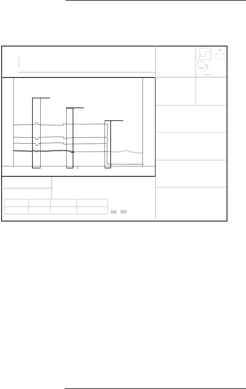
4 —5
4 —Trends
Graphical Trend Display
Two physiological parameters may be displayed at the same time in
the graphical trend window. For IBP and NIBP the pressure values for
diastolic, systolic and mean will be represented. The line graphs are
shown in the color selected by the user for trend displays.
Figure 4-3: Graphical Trend Screen
The sample graphical trend screen above shows HR and arterial IBP
data from IBP channel one (IBP1). The IBP data is displayed as a set
of thinner black lines for systolic, MAP, and diastolic values
respectively. (On the monitor screen the IBP data is represented in
the color selected by the user.) The lowest of the four lines is the HR
information. The color of the heart rate line is user-selectable in the
Trend Setup menu.
NOTE: The color of the heart rate waveform remains the color the
user set it as. The illustration above shows changes merely to
highlight the waveform as it changes its source.
10:12 a.m. Monitoring began.
4:00 p.m. IBP event is recorded.
10:00 p.m. ECG leads removed. (HR defaults to IBP)
4:00 a.m. IBP lines removed. (HR defaults to SpO2)
10:12 a.m. Current HR from SpO2 source.
ALARMS PARAMS DISPLAY
ALARMS PARAMS DISPLAY
ADM/DIS CONFIG PRINT
ADM/DIS CONFIG PRINT
Art1:NO XDUCER
Art1:NO XDUCER
14:12:59
14:12:59
II
II
T1
T1
ºC
ºC
T2
T2
%
IBP1 ART
IBP1 ART
EXP
EXP
INS
INS
MAP
MAP
ZERO IP1
ZERO IP1
ZERO IP2
ZERO IP2
CYCLE OFF
CYCLE OFF
NIBP AGE 24;18 min mmHg
NIBP AGE 24;18 min mmHg
Br/m
Br/m
1mV
1mV
SpO2
SpO2
IBP2 CVP
IBP2 CVP
mmHg
mmHg
150 ml/min
150 ml/min
mmHg
mmHg
mmHg
mmHg
CO2
CO2
GAS O2
GAS O2
HAL
HAL
N2O
N2O
HR
HR
%
EXP
EXP
INS
INS
BPM
BPM
RESP
RESP
60
60
98 98
98
37.1
37.1
27
27
37.1
37.1
20
20
8
8
ECG:LEADS OFF
ECG:LEADS OFF
17
17
11.0 39
11.0 39
21
21
10.5 64
10.5 64
- +
+
147/89
147/89
(107)
(107)
- +
+
John Smith
John Smith
(125)
(125)
(13)
(13)
145/105
145/105
SpO2
SpO2
300
300
10:12
10:12
JUN-18-04
JUN-18-04
10:12
10:12
JUN-18-04
JUN-18-04
0-10
-10
145
145
150
150
300
300
22:12
22:12
CO2
CO2
IBP1
IBP1
mmHg
mmHg
BPM
BPM
HR
HR
Adult
Adult
- +
4:00 PM
10:00 PM
4:00 AM

MEDRAD
Veris
8600
4 —6
Tabular Trends
Tabular Trend Markers
Various messages appear in the tabular trend to indicate that system
events have occurred. A complete list is as follows:
STNDBY ON STNDBY OFF
AGT STNDBY ON AGT STNDBY OFF
AUDIO ON AUDIO OFF
FREEZE ON FREEZE OFF
SIM ON SIM OFF
NEW PAT POWER
NOTE: Permanent silence and two minute silence are both recorded
as an AUDIO ON/OFF event in the tabular trend table.
Trend Messages
The trend also records messages in the trend table that indicate the
status of the monitor at that time. The time and date stamp is also
recorded when a marker is recorded. All messages appear in the
trend table regardless of the interval selected for the table or the time
that the message occurred. Markers are recorded for:
• Standby Mode is entered or exited (STNDBY ON/STNDBY
OFF);
• Agent Standby Mode is entered or exited (
AGT
STNDBY ON/
AGT
STNDBY OFF);
• Silence Mode (both two minute and permanent) is entered or
exited (AUDIO ON/AUDIO OFF);
• Waveforms are frozen or unfrozen (FREEZE ON/FREEZE
OFF);
• Power is turned on or off (POWER); or
• A new patient is admitted or discharged via the ADM/DIS
window (NEW PAT).
NOTE: If the patient size is changed while admitting a new
patient all the previous trend data is cleared.
At midnight the monitor records the date change into the trend table.
This does not occur if the monitor was turned off at midnight.

4 —7
4 —Trends
Data Format
The parameters are listed in the first column followed by the units.
• Time stamps at the half minute mark are displayed with a plus
“+” sign.
• Measured parameters that exceed or drop below alarm limits
are highlighted.
• When a sampling module is on and no value can be determined
for the parameter, three dashes “---” are displayed in the trend
table.
• If a sampling module is turned off in the PARAMS window, the
word OFF displays in the trend.
• If a sampling module is turned on and no valid measurement
has been taken, the word ERR displays in the trend if the
parameter has an error condition.
• If there is no NIBP data for a particular time stamp, the NIBP
trend area is left blank.
NOTE: The Trends are automatically cleared when the DATE/TIME is
changed.
_______________________________________________________
18-JUN-04 11:45+ 11:45 11:44+ 11:44 11:43+ 11:43
RATE BPM 60E 60E 60E 60E
SpO2 % 99 99 99 98 NEW POWER
NIBP SYS mmHg PAT
DIA mmHg
MAP mmHg
TEMP 1 °F 98.6 98.6 98.6 98.6
TEMP 2 °F 98.6 98.6 ERR ERR
RESP Br/m 20C 20C 20C 20C
IBP1 SYS mmHg 145 144 144 146
DIA mmHg 105 105 105 105
MAP mmHg 125AR 124AR 124AR 126AR
IBP2 SYS mmHg
DIA mmHg
MAP mmHg 13CV 13CV 13CV 13CV
_______________________________________________________
Figure 4-4: Sample Trend Table (Base and Cardiology)
For the trend table shown the interval is set to 30 seconds.

MEDRAD
Veris
8600
4 —8
Anesthesia units display two trend screens. The default is Basic
Trend Display. Select Advanced Trend Display for Trend Screen in
the Trend Setup Window to view the second tabular trend screen.
The Basic Trend Display screen displays:
• Heart rate
•SpO
2
• NIBP (Systolic, Diastolic, and MAP)
• Temp 1 and 2
• Respiration
•CO
2 (Inspired and Expired)
•O
2 (Inspired and Expired)
• Agent (Inspired and Expired)
•N
2O (Inspired and Expired)
_______________________________________________________
18-JUN-04 11:45+ 11:45 11:44+ 11:44 11:43+ 11:43
RATE BPM 60E 60E 60E 60E
SpO2 % 99 99 99 98 NEW POWER
NIBP SYS mmHg PAT
DIA mmHg
MAP mmHg
TEMP 1 °F 98.6 98.6 98.6 98.6
TEMP 2 °F 98.6 98.6 ERR ERR
RESP Br/m 20C 20C 20C 20C
CO2 INS mmHg 8 8 8 8
EXP 27 27 27 27
O2 INS % 21 21 21 21
EXP 17 17 17 17
AGT INS % 10.5H 10.5H 10.5H 10.5H
EXP 11.0 11.0 11.0 11.0
N2O INS % 64 63 64 64
EXP 39 39 39 39
_______________________________________________________
Figure 4-5: Sample Basic Trend Display Table
The Advanced Trend Display screen displays:
• IBP1 (Systolic, Diastolic, and MAP)
• IBP2 (Systolic, Diastolic, and MAP)
_______________________________________________________
18-JUN-04 11:45+ 11:45 11:44+ 11:44 11:43+ 11:43
IBP1 SYS mmHg 145 144 144 146
DIA mmHg 105 105 105 105
MAP mmHg 125AR 124AR 124AR 126AR
IBP2 SYS mmHg
DIA mmHg
MAP mmHg 13CV 13CV 13CV 13CV
_______________________________________________________
Figure 4-6: Sample Advanced Trend Display Table
NOTE: The Advanced Trend Display screen only displays IBP
information. To view trend data of the other parameters, you must
reset Trend Screen in the Trend Setup Window to Basic Trend
Display.

4 —9
4 —Trends
HEART RATE SOURCE INDICATION
The source of the heart rate data is indicated by a letter following
each heart rate value.
• E = electrocardiogram,
• I = invasive blood pressure,
• S = pulse oximetry and
• N = Non-invasive blood pressure.
IBP SITE INDICATION
The IBP site is indicated by a letter following each mean value.
• AR = Arterial (ART)
• PA = Pulmonary Artery (PA)
• CV = Central Venous (CVP)
• RA = Right Atrial (RA)
• LA = Left Atrial (LA)
• IP = Intracranial (ICP)
• RV = Right Ventricle (RV)
• LV = Left Ventricle (LV)
RESPIRATION SOURCE INDICATION
The source of the respiration data is indicated by a letter following
each respiration value.
• C = capnometer (CO2 module).
AGENT SOURCE INDICATION
The agent source is indicated by a letter following the inspired value
for the agent.
• H = Halothane
• E = Enflourane
• I = Isoflourane
• D = Desflurane
• S = Sevoflurane
•U = Unknown

MEDRAD
Veris
8600
4 —10
Clearing the Memory
To clear the trend memory:
1. Press the TREND key to display the trend.
2. Press and hold TREND key again to display the trend setup
window.
3. Select the clear trend option and select YES to confirm the
clearing of the trend data.
The trend memory is automatically cleared when:
• The time and/or date are changed in the menu
• The patient size is changed (adult/pediatric/neonate).

5 —1
5 — ECG
Theory of Operation
Heart Rate
The heart rate is determined primarily from the ECG waveform data.
The monitor has a user selectable smart heart rate function. It
automatically uses alternate sources to determine heart rate, if the
primary source becomes unavailable.
• The IBP pulse rate is used if the ECG waveform data is
unavailable.
• The SpO2 pulse rate is used if the ECG and the IBP waveforms
are not available.
• The NIBP pulse rate is used if the ECG, the SpO2, and the IBP
waveforms are not available.
Response times for ECG heart rate meter change from 80 BPM to 40
BPM and from 80 BPM to 120 BPM is less than or equal to 10
seconds.
NOTE: The accuracy and range of the heart rate depends upon the
source. See “Specifications” in Appendix C.
NOTE: The NIBP-based heart rate is not a continuous measurement
and is only current during an NIBP measurement.
ECG Measurement
The electrocardiogram (ECG or EKG) records the changing potential
generated by electrical activity of the heart.
Electrical currents influenced by the cardiac impulse flow through the
body tissue around the heart. Electrodes, placed on the skin on
opposite sides of the heart, transmit the electrical potentials to
circuitry in the ECG module, which in turn amplifies, digitizes
(converts analog signals to digital signals), and transmits this
information to the
Veris
8600 patient monitor by means of light pulses
traveling through fiber optic cable.
The
Veris
8600 patient monitor ECG circuitry filters these received
signals. The signals are used to display the ECG waveform to the
user and to create a waveform and a pulse for scanner gating. Two
different filter types are used. One filter is employed to display the
ECG signal while the second filters the signal for gating purposes.
For more information on gating see “Gating Signals” on page 5-3

MEDRAD
Veris
8600
5 —2
METHOD
To obtain an overall view of the heart's electrical activity, three or five
electrodes attached to a leadset detect electrical impulses from the
patient's heart to the skin. The monitor calculates the difference in
electrical force between two electrode sites. Electrode polarity
(positive, negative, or ground) depends on the cable receptacle the
lead cable is attached to and the lead selected on the monitor screen.
The ECG circuitry amplifies, filters, and digitizes (converts analog
signals to digital signals) the received electrical potentials. The ECG
module converts these electrical signals into light pulses which the
monitor receives and converts back into a recognizable signal.
The ECG design provides for standard 3-lead, or on some systems
5-lead, monitoring. The 3-lead ECG provides conventional bipolar
limb leads (I, II, III). The 5-lead ECG provides additional aVR, aVL,
aVF, and V views.
The monitor has automatic lead switching capability for 5-lead
monitoring, which may be selected by the user. If a lead becomes
detached or is unmeasurable, the monitor can automatically display
an alternate lead view using the remaining leads.
STABILITY OF ACCURACY
The accuracy of the monitor is not affected by arrhythmia or other
physiological conditions where the electrocardiogram amplitude and
heart rate are within the detectable limits specified for the monitor.
The monitor has signal filtering in the 60 Hz and 50 Hz bands that
reduce electrical interference from the AC (mains) power sources.
The accuracy of the ECG is affected by the static and gradient
magnetic fields. Determine only rate and rhythm with the patient in
the presence of a static and gradient magnetic field.
If a defibrilator is used on a patient, the ECG traces disappear. The
traces resume within 10 seconds after defibrilation is complete.
ECG module
The ECG module uses a Fiber Optic Transmit/Receive technology. The
ECG module is a battery-powered, fiber optic interface from the patient
to the monitor.

5 —3
5 —ECG
Gating Signals
The input gating signal is derived from any one of two sources—ECG
or Plethysmogram (SpO2) waveform and is available in 2
user-selectable forms, pulse or waveform. An icon of the gating signal
source and a visual indication appears at the upper left corner of the
heart rate numerical display box.
ECG GATING
Electrical currents influenced by the cardiac impulse flow through the
body tissue around the heart. Three or five electrodes, placed on the
skin on opposite sides of the heart, transmit the electrical potentials
to circuitry in the ECG module, which in turn transmits this
information to the
Veris
monitor by means of light pulses. This
information is further transmitted to the ECG gating interface. The
ECG gating interface then produces a signal out, which can be used
by the MR scanner electronics to cardiac gate an MR scan. The
coupling between the ECG module and the
Veris
monitor, and
between the
Veris
monitor and the gating interface, provides complete
isolation of the patient from the gating interface and MR scanner.
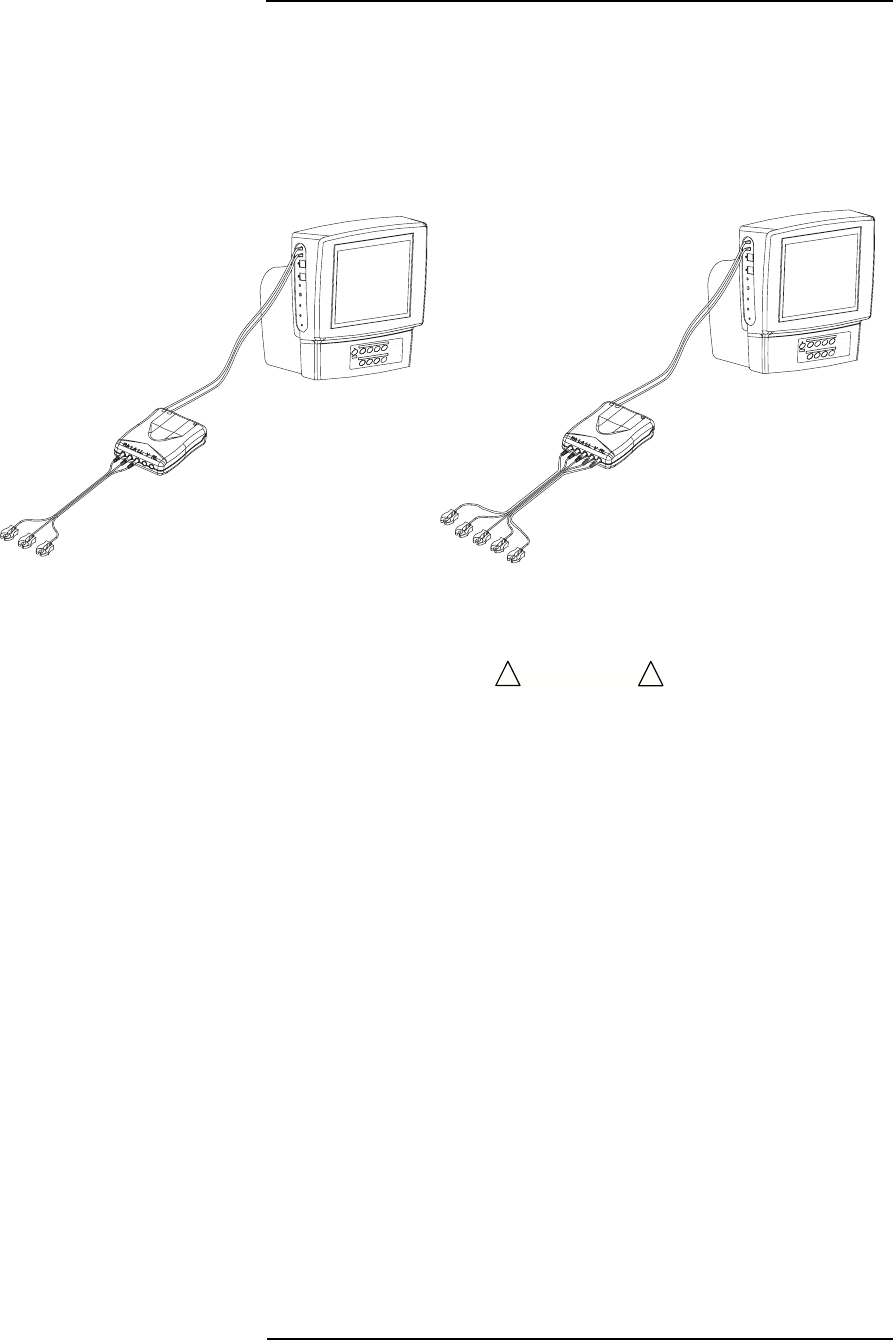
MEDRAD
Veris
8600
5 —4
ECG Monitoring
(Electrocardiogram)
The following instructions describe procedures for preparing a patient
for ECG monitoring.
Shown below is the patient monitor with a fiber optic cable, ECG
module, and a 3-lead leadset (left) and a 5-lead leadset (right)
attached.
Figure 5-7: ECG Cable Connection with the ECG Module
• Use only recommended leadsets. The use of leadsets not
recommended could result in injury, such as patient burns. Use
only the leadset that is included with your
Veris
monitor.
• Use only recommended electrodes. The use of other electrodes
could result in injury, such as patient burns. Use only ConMed
Invisatrace electrodes or other electrodes specifically
recommended by Medrad with the
Veris
monitor.
• The ECG signal is not intended for diagnostic use. Interference
due to static and gradient magnetic fields can occur. Determine
only rate and rhythm during ECG use.
• This device is not intended for intracardiac ECG applications.
Use the ECG monitor and accessories only as directed.
• Do not place defibrillator paddles on or next to ECG patient
electrodes. Contact between defibrillator paddles and ECG
electrodes could injure the patient.
• The conductive parts of the ECG electrodes should not come in
contact with other conductive parts, including earth ground.
Such contact could result in patient injury, death, or equipment
damage.
WARNING
!!

5 —5
5 —ECG
• There is no defibrillator synchronization output on the
Veris
monitor. Make no connections between the
Veris
system and a
defibrillator.
• PACEMAKER PATIENTS: This device does not include
pacemaker spike rejection capability. Heart rate readouts
derived from the ECG patient connections are likely to display
erroneous high or erratic rates when a pacemaker is in use.
Keep pacemaker patients under close surveillance. For
pacemaker patients it may be advisable to select the SpO2
function as the primary heart rate source.
• The heart rate calculated by the ECG module may be affected
by cardiac arrhythmia.
• Leakage currents may increase if other equipment is
interconnected to the patient. The increased leakage currents
may present a hazard to the patient.
• ECG electrodes can cause skin irritation. Change the electrodes
and reposition every 24 hours or sooner if there is sign of
inflammation.
• Place the ECG module out of the imaging volume. Make certain
that the module is stationary (i.e., not moving or vibrating)
• All metallic wires going into the magnet bore will drain off RF
power; the fiber optic cables are non-conductive and will not
drain off power or heat up. For RF exposures up to specific
absorption rates (SAR) of 2.0 W/kg, the ECG leads will not
cause patient burns when they are properly insulated and free
of loops. Monitoring of ECG at very high RF exposures, above
2.0 W/kg, is not recommended for the general patient
population. Such monitoring should be attempted on conscious
patients with good temperature reflex so they may warn the
operator of excessive heat at monitoring sites.
• All cables should be watched carefully during patient loading
and unloading to avoid entanglement with the patient table
mechanisms. Cables and the ECG module should not be
permitted to swing or move during scanning to avoid baseline
wander.
• The "T" wave may become excessively large or inverted with the
patient in the magnetic field. This effect is due to
electromagnetic flow induced voltage and may interfere with
QRS detection. Try other leads and/or electrode placements for
best results.
WARNING
!!
CAUTION
!!

MEDRAD
Veris
8600
5 —6
Protection
The ECG module protection against electric shock is of Type CF with
protection against the effects of defibrillation.
ECG Performance
The
Veris
monitor properly counts normal rhythms with T-Wave
heights to 80% of the QRS height at a heart rate of 80 BPM.
• The presence of tall T-waves greater than 80% of the R-wave
may result in a double counting of beats.
The
Veris
8600 monitor complies to AAMI EC13-2002 with
exceptions. The monitor does not reject beats of 10ms or less in
duration and 1mV or less in amplitude per EC13 section 5.2.6.
The monitor employs a one Hertz filter that allows extraction of ECG
waveforms in an MRI environment. Although this design deviates
from requirements of EC13 per sections 5.2.9.7 and 5.2.9.8, there is
a minimal affect to the aspect ratio, impulse response and the ST
component of the ECG waveform.
The
Veris
monitor does not provide pacemaker pulse detection and
pacer indication per EC13 section 5.2.9.12 and ESU suppression is
not provided per section 5.2.9.14. Since the monitor is intended for
indoor use, the functional ECG temperature range is specified as
15° C to 35° C.
Electrode Selection
MEDRAD recommends using ConMed Invisatrace electrodes. These
electrodes are MRI safe.
See “Accessories” in Appendix D for a complete list of recommended
electrodes and accessories.
WARNING
!!
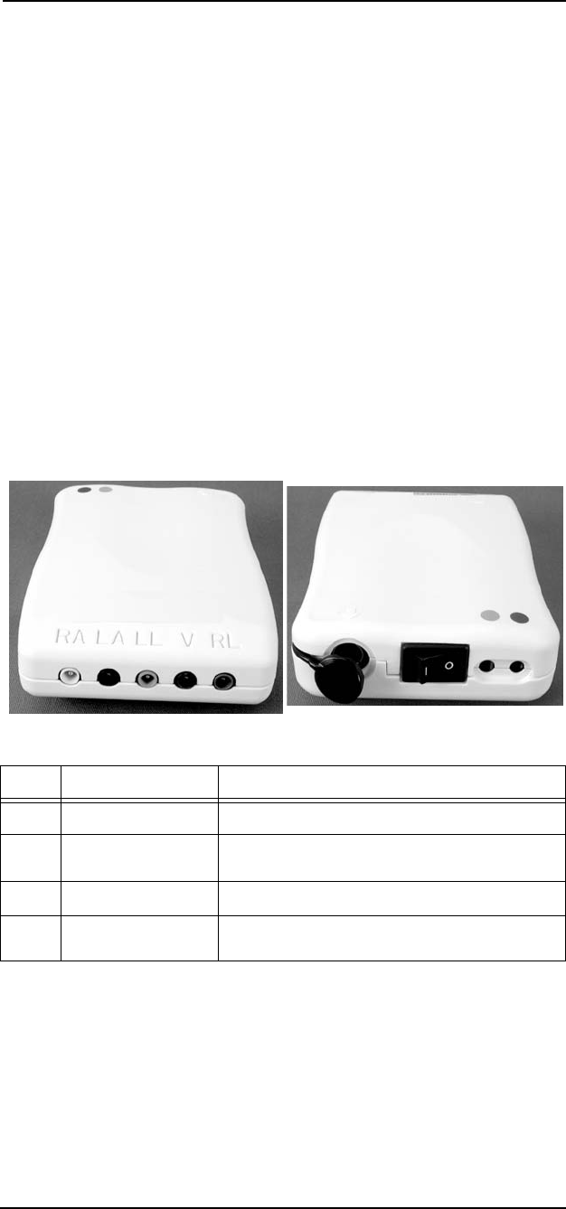
5 —7
5 —ECG
ECG Module Interface
The ECG module is a battery-powered, fiber optic interface from the
patient to the monitor. The module has five color-coded connectors
along its front surface to interface with the ECG leadsets and 2 color-
coded fiber-optic connectors on the rear surface to interface with the
Veris
monitor.
NOTE: The ECG module protection against electric shock is of type
CF, with protection against the effects of defibrillation.
NOTE: Always keep the ECG module on the charger when not in use,
or when anticipating a period of prolonged inactivity.
The ECG module contains an internal, rechargeable battery. A power
switch is provided on the rear of the module. When the monitor is not
in use, make certain that the power switch on the ECG module is off
to extend battery life. The battery is not user-serviceable and cannot
be replaced.
ECG Module Ports And Switches
The following graphic and table details the ports and switches on the
ECG module.
Figure 5-8: ECG Module Ports, Switches
Item Name Description
1Patient Connectors Color-coded connections for ECG leadset.
2Battery charger
connection Port for plugging the ECG module to the
charger.
3Power Switch This is the power on/off switch.
4Connection to
monitor Fiber optic input/output connections to send
ECG signal to the monitor.
1
234

MEDRAD
Veris
8600
5 —8
• Do not charge the ECG module battery while the ECG module
is connected to the patient! Charging the ECG module battery
during patient use can lead to electric shock through the
leadset.
• Do not take the ECG module charger into the magnet room! The
ECG module charger contains ferromagnetic material and may
be attracted to the magnet, resulting in patient or operator injury.
• The ECG module contains non-servicable batteries. Improper
disposal of batteries may result in explosion, leakage, or
personal injury. Do not open the batteries. Do not dispose of the
batteries in a fire. Follow all local regulations concerning the
disposal of spent Lithium-Ion batteries or contact Medrad for
assistance.
• Only use the
Veris
ECG module charger to charge the module.
Use of other chargers may damage the module and/or charger.
Do not use the charger on other devices as this may damage
the charger and/or device.
NOTES:
When not in use, turn off the ECG module to extend battery life.
Charge the ECG module at least once per week.
Keep the charger cover on the ECG module closed, except when the
module is being charged. This protects the connector from moisture
or foreign objects.
Battery Condition
When the module is connected and switched on, the ECG module
battery icon on the monitor display indicates the status of the battery.
GREEN: The battery is good; greater than 7 hours of
continuous use remaining
YELLOW: The battery is low; less than 7 hours of continuous
use remaining. Charge the module as soon as
possible.
BLACK: The battery is dead or no communication. Check the
power switch and the fiber optic cable. Recharge the
battery prior to use.
WARNING
!!
CAUTION
!!
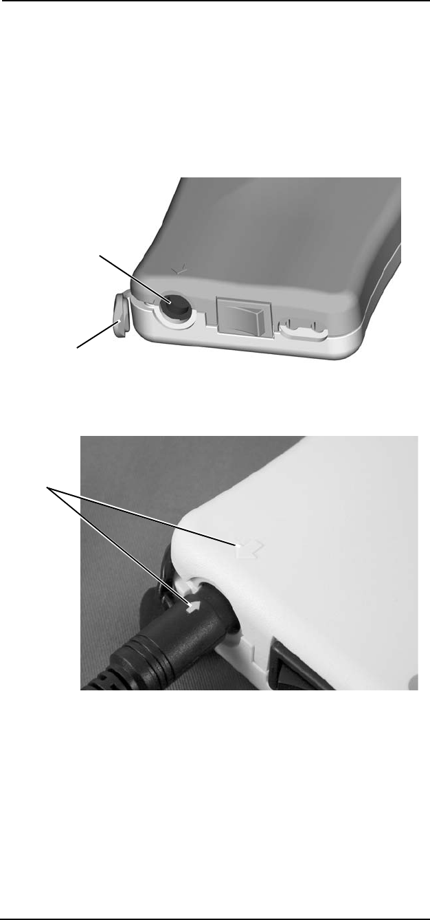
5 —9
5 —ECG
Charging the
Battery
Charge the ECG module at least once per week using the provided
charger. Charge the module only when it is not in use and not
connected to a patient.
1. Plug the charger into an AC outlet, outside the magnet room.
2. Ensure the ECG module is disconnected from the patient and
that the module power switch is in the OFF position.
3. Open the charger cover on the ECG module.
Figure 5-9: Charger Connector Detail
4. Align the arrow on the charger cable with the arrow on the ECG
module and insert the cable firmly into the module.
Figure 5-10: Align the Arrows
Charger
Connector
Charger
Cover
Arrows

MEDRAD
Veris
8600
5 —10
5. Confirm that the module is charging by observing the indicator
on the charger and using the instructions printed on the charger.
Figure 5-11: Charging with Indicator Light
6. The ECG module charges in 3 hours or less. Observe the
charger indicator to determine when the module is fully charged.
7. Remove the charger cable from the module and close the
charger connector cover.
Charger
Indicator

5 —11
5 —ECG
ECG Monitoring
Patient Preparation
Proper patient preparation and placement of the electrodes is the
single most important factor in obtaining a good ECG signal.
1. Have a thorough understanding of the patient’s history. This may
assist in determining where electrodes are placed.
2. Prepare the patient by ensuring that hair is removed from the
locations where you intend to place the electrodes. Use
Nu-Prep gel with cotton gauze or a washcloth. A small amount
of Nu-Prep gel should be applied to the cotton gauze or wash
cloth. The area where the electrode is to be placed should then
be thoroughly cleaned by rubbing it in a circular motion.
3. ConMed Invisitrace electrodes are recommended for use with
the
Veris
monitor. They should be placed on the prepared
locations ensuring that they securely adhere to the skin surface.
NOTES:
Do not use alcohol. Alcohol removes electrolytes from the skin
and decreases the quality of the electrical contact.
Medrad recommends the use of ConMed Invisitrace electrodes.
These electrodes are MRI compatible. See “Accessories” in
Appendix D for a complete list of recommended electrodes and
accessories.
Use three (or five) new, MR-compatable electrodes.
• Connect only MEDRAD approved 3-lead or 5-lead ECG cables
from the patient to the ECG module. Do not connect any other
signal source to the ECG module.
• When positioning the patient in the MR scanner, locate the
electrodes less than four inches from each other and do not loop
the leadset. Insulate the leadset from the patient. It is not
dangerous for loops to form in the fiber optic cable.
• Use only accessories designated for use with this monitor. Use
of accessories not designated for use with the
Veris
monitor can
cause inaccurate measurements and/or a safety hazard for the
patient.
• Do not allow the conductive parts of the patient electrodes to
contact other conductive parts, including ground (earth).
WARNING
!!
CAUTION
!!
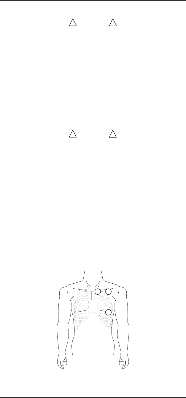
MEDRAD
Veris
8600
5 —12
• Static magnetic fields can cause reversible electrocardiogram
changes. Determine only rate and rhythm with the patient in the
presence of a static magnetic field.
• High Frequency (HF) surgical equipment may affect the
operation of the ECG unit. The system is not designed to
operate in the presence of ESU interference.
Lead Placement
The monitor provides ECG options for 3- and 5-lead patient setups.
The following instructions describe both the 3- and 5-lead
configurations. It is important to use the MEDRAD recommended
leadset to ensure patient safety.
• When positioning the patient in the MR scanner, locate the
electrodes less than four inches from each other and do not loop
the leadset. Insulate the leadset from the patient.
3-LEAD SETUP
The three major planes that detect electrical activity are Lead I, Lead
II, and Lead III, known as the standard or conventional bipolar limb
leads. Lead II (RA and LL), commonly known as the standard lead
configuration, is often used for monitoring because its waveform
characteristics are typically most prominent. For general monitoring
purposes, Leads I and II are most commonly used.
• Lead I produces good P waves, reflecting atrial activity.
• Lead II produces good QRS complexes, reflecting ventricular
activity.
Place the electrodes on the patient as shown in the illustration below.
Leads I, II, III may be selected in the monitor’s DISPLAY window.
Figure 5-12: Electrode Locations for 3-Lead Setup
CAUTION
!!
CAUTION
!!
LA
LL
RA
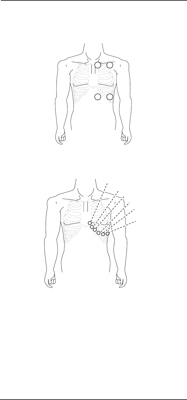
5 —13
5 —ECG
5-LEAD SETUP
Place the electrodes on the patient in the 5-lead configuration as
shown in the illustration below. Leads I, II, III, aVL, aVF, aVR, or V
may be selected in the monitor’s DISPLAY window.
Figure 5-13: Electrode Locations for 5-Lead Setup
The V lead (chest lead) in a 5-lead configuration can be placed in one
of six standard positions.
Figure 5-14: Electrode Locations for the V Lead
RA
RL LL
LA
V
1
V
2
V
3
V
4
V
5
V
6

MEDRAD
Veris
8600
5 —14
Connecting Patient
to the Monitor
NOTE: Inspect the ECG module cable and connections regularly for
signs of mechanical damage (e.g., cracked insulation, crimped, or
bent wires).
1. Attach the electrodes as described in “Lead Placement” on
page 5-12 and following.
2. Press the ON/OFF or STANDBY button on the
Veris
monitor.
3. Make sure the ECG function is ON.
a. Select the PARAMS menu with the menu knob.
b. Select ECG.
c. Rotate and press the menu knob to select ON.
4. Choose the appropriate lead set cable and select this on the
monitor.
a. Select the PARAMS menu with the menu knob.
b. Select LEAD SET.
c. Rotate and press the menu knob to select the correct lead
set.
d. Select EXIT to return to the main display.
5. Connect the color-coded graphite lead wires to the
corresponding connections on the ECG module.
Figure 5-15: ECG Module Connected to Monitor
6. Connect the color-coded fiber optic cable to the corresponding
colors on the ECG module.
7. Connect the color-coded fiber optic cable to the corresponding
ECG connections on the main monitor.
6
7

5 —15
5 —ECG
NOTES:
To remove the fiber optic ECG cable, grip the cable connectors
at the end of the cable and pull back firmly. Do not pull on the
fiber optic cable to remove it from the monitor or ECG module.
To remove the lead set from the ECG module, grip the
connectors at the module end of the lead and pull straight out.
Do not pull on the leads themselves.
The ECG leads and connections should be inspected regularly
for signs of mechanical damage (e.g., cracked insulation,
crimped or bent wires).
8. Turn on the ECG module. The ECG module battery icon should
display on the monitor screen.
GREEN: Communication is established and the battery is
good.
YELLOW: Communication is established but the battery is
low.
BLACK: Communication is not established or the battery is
dead.
An informational message should appear that the leads are not
connected to the patient.
9. Setup the display for the desired lead set combinations.
a. Select the DISPLAY menu with the menu knob.
b. Select the desired waveform.
c. Select an ECG lead combination and configure other display
parameters. See “DISPLAY Softkey” on page 2-27 for a
detailed description of configuring the display.
10.Keep the ECG module outside of the patient imaging volume.
NOTES:
Position the ECG module out of the imaging plane. (On the
shoulder if scanning the chest or torso or in the antecubital
space if scanning the neck or head.)
Make certain that the ECG module is stationary (not moving or
vibrating).
11.Carefully attach the color-coded lead set to the electrodes
(White=RA, Black=LA, Red=LL, Green=RL, and Brown=V),
ensuring good connections.
12.The ECG waveform(s) should display on the monitor in
approximately 5 seconds.
Completion of ECG Monitoring
To remove the ECG module cable, grip the cable connectors and pull
back firmly. Do not pull on the cable to remove it from the monitor.

MEDRAD
Veris
8600
5 —16
ECG Auto Lead Switching
The monitor may have the ability to display alternate leads in cases of
fault in the selected lead while the unit is set for 5 lead ECG.
The monitor uses the RA electrode in deriving all lead views.
Therefore, failure of the RA electrode results in no leads being
available. The monitor identifies the RA electrode as having failed
with the message ECG LEADS OFF. The same message displays
when both the LA and LL electrodes fail.
Lead failure assumes that the signal is lost from an electrode that is
required for the desired lead view. Loss of a signal from unnecessary
electrodes does not cause lead switching.
Primary Lead
The monitor identifies a primary lead that is used to report heart rate
numerical data. If no leads are displayed, the primary lead defaults to
lead II. If ECG waveforms are displayed, the monitor selects the
waveform closest to the top of the screen as the primary lead. Lead
switching only occurs in the primary lead view.
Lead failure during monitoring causes one of the following results:
1. If a failure occurs in the primary lead, while currently being
displayed, the system attempts to switch from the current lead
view to an alternate lead view.
The system switches to a valid (non-failed) lead view if a valid
lead exists. The failed electrode is indicated by an alarm
message. The slot label of the primary lead visibly changes to
the new lead view. The alternate waveform is drawn in the slot.
2. If the failure occurs for Lead II, while no ECG leads are
displayed, the primary lead is changed to an alternate lead. The
smart heart rate is determined from the new lead view. No lead
switching is apparent from the main screen.
3. If no alternate is available for a primary lead, an ECG: LEADS
OFF alarm is generated. The smart heart rate defaults to the
next available source, indicated by a change of the heart rate
numerical display. No lead switching occurs.
4. If the required electrodes for a displayed non-primary lead are
not available, an error message displays. The waveform
becomes a straight line. No lead switching occurs.
When the lead fail condition is corrected, the system reverts back to
the original lead that displayed before the fail condition occurred.

5 —17
5 —ECG
Alternate Lead Priority
The ECG monitor automatically determines lead switching as shown
below.
NOTE: Lead switching is only available in 5-lead setup.
In cases indicated by a dash, no switching occurs, since the electrode
is unused for that selected lead. In cases where LL fails, no switching
occurs because that electrode is required for each selectable lead
configuration.
5 Lead
Electrode Off LL LA RA V RL
Primary Lead Alternative Lead
Lead I NONE II III — —
Lead II NONE — III — —
Lead III NONE II — — —
Lead V NONE II III II —
Lead aVL, aVR, aVF NONE II III — —
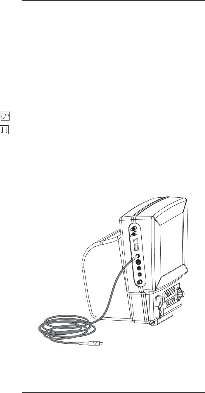
MEDRAD
Veris
8600
5 —18
Gating Interface
The source of the gating signal may arise from the ECG or SpO2. The
gating signal from either of these sources may be delivered to the
scanner in two user-selectable forms—waveform or pulse.
•Waveform output: one of the following: 1mV ECG waveform or
a plethysmogram (SpO2) waveform.
•Pulse output: 1mV pulse amplitude and 50 msec pulse width,
synchronous with the r-wave or corresponding peak of the
plethysmogram (SpO2) waveform.
The delay time from detection of the ECG signal at the patient to the
input of the MR scanner is less than or equal to 5 milliseconds.
One of two icons appears in the upper left corner of the heart rate
numerical display box. These icons represent the gating signal
output—either waveform or pulse. The icon is the same color as the
ECG waveform color. See Step 6 below.
The gating function is user-selectable: OFF, ECG Waveform, ECG
Pulse, SpO2 Waveform, or SpO2 Pulse. The default is OFF.
1. Connect the cable appropriate for the scanner to the GATING
connection on the
Veris
patient monitor.
NOTE: The gating cable must be IEC 950 or IEC 60950
compliant.
Figure 5-16: ECG Gating Connection
Waveform Output
Pulse Output

5 —19
5 —ECG
2. Connect the MR scanner end of the cable to the scanner
interface receptacle.
NOTES:
To remove the gating cable, grip the cable connectors from both
ends and pull back firmly. Do not pull on the gating cable to
remove it from the monitor or scanner.
Inspect the gating cable and connections regularly for signs of
mechanical damage (e.g., cracked insulation, crimped, or bent
wires).
3. Setup the display for the desired lead view for the gating source
in the Waveform 1 position.
a. Select the DISPLAY menu with the menu knob.
b. Select Waveform 1.
c. Select the ECG lead to use for the ECG gating source. See
“DISPLAY Softkey” on page 2-27 for a detailed description of
configuring the display.
4. Using the PARAMS menu select Gating and then select either
ECG Wave or ECG Pulse.
5. Configure the scanner in accordance with the manufacturer’s
recommendations. If using the universal EGC gating cable,
always select Lead II on the scanner console.
NOTE: In the event that the desired lead view is not available,
the monitor switches to alternate lead views if possible, using
the priorities specified in “ECG Auto Lead Switching” on page 5-
16.
6. An ECG waveform displays if the ECG waveform is selected for
gating. If a pulse is selected a spike appears in place of the
waveform. The waveform or “spike” is transmitted to the MR
system.
NOTE: Always select LEAD II on the MR scanner console. If
you wish to use another configuration (I, II, III, aVL, aVR, or
aVF), make this change at the
Veris
8600 patient monitor.
Selecting a lead configuration other than II at the MR scanner
console may result in incorrect or no gating action.
7. The LEAD SELECT control on the patient monitor can select
either LEAD I, II, or III (or, with 5-lead configuration, aVL, aVR,
or aVF).
8. In the event one of the leads is disconnected, LEAD OFF
displays on the patient monitor screen.

6 —1
6 — NIBP
Theory of Operation
The monitor uses ComfortCuff™ technology to determine non-
invasive blood pressure by means of oscillometry. The oscillometric
method detects volume displacements within the artery and senses
pressure variations within the blood pressure cuff during inflation.
The monitor uses cuffs ranging in size from neonate to adult thigh.
Heart Rate
The NIBP pulse rate is used if the ECG, the SpO2, and the IBP pulse
rates are not available. See “Heart Rate” on page 5-1 for more
information.
Comfort Cuff™ Technology
ComfortCuff™ technology measures NIBP while the cuff inflates.
Consequently, a measurement is obtained more quickly and with less
discomfort than with monitors which measure NIBP during cuff
deflation.
Description of NIBP
Measurement
The NIBP cuff begins to inflate at the beginning of the NIBP
measurement cycle. As the cuff pressure approaches the diastolic
pressure of the patient, the cuff pressure waveform begins to indicate
the pulse waveform (see “Figure 6-1: NIBP Cuff Pressure and Pulse
over Time” on page 6-2). The cuff pressure at this point is equal to
the patient’s diastolic pressure, which is stored by the monitor.
As cuff pressure continues to increase, the pulse waveform (as
measured from BP cuff pressure fluctuation) becomes stronger,
reaching its maximum at the patient's mean arterial pressure (i.e.,
when cuff pressure = mean BP). The monitor stores this value as
mean pressure.
As cuff pressure increases further, it approaches the patient’s systolic
pressure, and the cuffs pulse waveform decreases in amplitude. The
cuff pulse waveform disappears at the point where cuff pressure is
equal to the patient’s systolic pressure.
When the monitor determines that the cuff waveform has decreased
to zero amplitude, it stores the cuff pressure value as the systolic
pressure, and releases the pressure from the cuff. This typically
occurs at about 10 mmHg over the patient’s systolic pressure. The
cuff then rapidly deflates.
NIBP Clinical Testing
and Accuracy
This device was clinically tested per the requirements of EN 1060 and
AAMI SP-10. The NIBP module as installed in the
Veris
8600 monitor
has been tested to meet the performance specifications listed in this
manual.
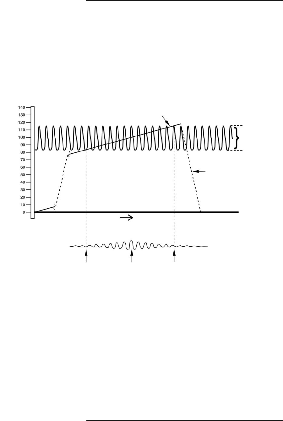
MEDRAD
Veris
8600
6 —2
Cuff Inflation and
Pressure Protection
The maximum cuff inflation rate is 15 mmHg/sec. The software limits
inflation to 300 mmHg adult, 300 mmHg pediatric, or 150 neonate. A
secondary circuit limits maximum possible cuff pressure to 316
mmHg in adult/pediatric mode and 158 mmHg in neonatal mode. Cuff
pressure is allowed to remain above 30 mmHg for a maximum of 2
minutes.
The monitor automatically deflates the cuff if the time limit is violated.
The monitor contains hardware protection for overpressure
conditions, pressure transducer failures, or microprocessor and pump
control circuit failures.
Figure 6-1: NIBP Cuff Pressure and Pulse over Time
B.P Cuff Inflation Pressure
(Shown during inflation)
Systolic Pressure
Actual Blood
Pressure Waveform
Diastolic Pressure
Cuff deflates rapidly after
monitor determines
systolic pressure
Time
Diastolic
Pressure Mean
Pressure Systolic
Pressure
Pulse Waveform
(Measured from B.P.
Cuff Pressure
Fluctuation)
Pressure in mmHg
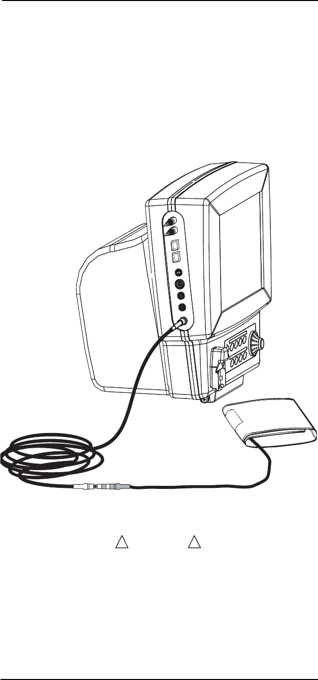
6 —3
6 —NIBP
NIBP Monitoring
The following instructions describe procedures for preparing a patient
for monitoring using the ComfortCuff™ NIBP module.
Shown below is the monitor with an adult size blood pressure cuff and
5 meter extension tubing. This adult arm cuff is one of many blood
pressure cuffs available. Use only NIBP accessories recommend by
MEDRAD. See “Accessories” in Appendix D.
The monitor has a quick connect/disconnect fitting for the NIBP
extension tubing. The patient end of the tubing has a threaded fitting
that accepts any MEDRAD NIBP cuff.
Figure 6-1: NIBP Cuff Connection
• Check the patient frequently to ensure the NIBP cuff is not
causing prolonged impairment of the patient’s circulation.
• Repeated use of the STAT mode should be avoided. Prolonged
or repeated use can lead to patient bruising.
WARNING
!!

MEDRAD
Veris
8600
6 —4
• Proper cuff size and placement is essential for accurate blood
pressure measurement.
• The accuracy of noninvasive blood pressure readings may be
adversely affected by the presence of drugs or therapies which
alter the patient's cardiovascular dynamics.
• The sensitivity of blood pressure measurement may be affected
when monitoring patients with intra-aortic balloon pumps.
• Ensure that the NIBP extension tubing is not compressed or
restricted in any way.
NOTE: The interval timer does not start until the NIBP key is pressed.
CAUTION
!!

6 —5
6 —NIBP
Selecting Cuffs and Hoses
MEDRAD blood pressure cuffs and extension tubes are
recommended for use with this monitor. Use of other brands of cuffs
may cause inaccurate measurements.
Proper cuff size and placement is essential to assure accurate blood
pressure measurement. The recommended cuff width-to-length ratio
is about 2:1, so that if the cuff width is 40% of arm circumference, the
cuff bladder length encircles 80% of the arm. A cuff that is too narrow
results in falsely high pressure readings. A cuff that is too wide results
in falsely low pressure readings.
The cuff shown below on the left is too small for the arm, therefore,
full cuff pressure is never applied to the artery. This causes an
erroneously high blood pressure reading. The cuff shown on the right
is of adequate width for the arm, and full cuff pressure is applied to
the brachial artery.
Figure 6-2: Blood Pressure Cuff Size
Cuffs for thighs are available for large patients or those where neither
arm is available for cuff placement. Blood pressure measured at the
thigh is typically 20-30 mmHg higher (when the patient is standing,
not prone) than blood pressure measured at the upper arm.
Cuffs for pediatric and neonate patients are also available in a variety
of sizes. See “Accessories” in Appendix D for available cuffs.

MEDRAD
Veris
8600
6 —6
Placing the NIBP Cuff
Wrap the cuff snugly around the extremity, leaving enough room
between the cuff and the extremity for two fingers. If the cuff is too
loose, it cannot be inflated properly and may cause errors in
measured BP values.
• It is best to wrap a bare extremity; putting the cuff over clothing
may cause errors in measured values.
• Care should be taken to center the dot on the cuff directly over
the brachial artery. (Shown below as a circle with a vertical line).
• The extension tube should not be twisted or kinked.
The end of the cuff (marked by an index line) should fall inside the
range marked clearly on the inside of the cuff. If not, use a different
size cuff.
Figure 6-3: Blood Pressure Cuff Size Range
Place this side against the skin
Este lado hacia la piel
Ce côte en contact avec la peau

MEDRAD
Veris
8600
6 —7
Procedure
1. Check the System Status Line for the correct mode. The status
line indicates Adult, Pediatric, or Neonate.
2. Select a cuff as described previously in this section.
3. Connect the BP cuff to the extension tube.
4. Connect the extension tube to the monitor.
5. Secure the cuff around the patient’s extremity.
6. Make sure there are no kinks or other obstructions in the
extension tube extending from the cuff.
7. Press the NIBP key on the front keypad of the monitor.
Pressing the NIBP key causes the monitor to take one measurement.
The monitor may make a second attempt if there is excessive motion
during the first attempt to take a measurement.
Press momentarily the NIBP CYCLE/STAT key to begin taking Stat
NIBP measurements. NIBP measurements are then taken repetitively
for 5 minutes. The numerical parameters on the display are updated
with each measurement.
If an NIBP cycle time has been selected the monitor automatically
takes NIBP measurements at scheduled intervals. Press the NIBP
key to begin measuring at automatic intervals.
If the monitor is placed in STANDBY MODE or AGENT ALARM
STANDBY MODE, the monitor does not take NIBP cycle time
readings.

MEDRAD
Veris
8600
6 —8
Taking NIBP Measurements
For optimum accuracy, the patient should keep the cuffed part of the
arm at the same level as the heart. NIBP measurement points above
the level of the heart give reduced pressure values. Measurement
points below the heart level give increased values. These errors are
due to the weight of the blood.
Figure 6-4: Arm Position for NIBP Measurement
An average measurement on a non-moving patient takes less than 40
seconds. At the end of each measurement, the cuff automatically
deflates. The monitor automatically attempts a second measurement
(with no displayed error message) if it cannot calculate a blood
pressure on the first inflation.
If a patient experiences a sudden dramatic drop in blood pressure,
the system may not measure the blood pressure on the first attempt.
The system automatically attempts another pressure measurement,
and detects the change on the second attempt.
Do not compress the cuff or the extension tube externally.
Compression of the cuff or the extension tube causes measurement
error. For optimum accuracy, the patient should remain still during
blood pressure measurement. Excessive patient motion may
adversely affect any oscillometric NIBP device.
Heart

7 —1
7 — SpO
2
Theory of Operation
The monitor uses Digital Oximetry (DOX™) technology to measure
blood oxygen saturation (SpO2).
Heart Rate
The SpO2 pulse rate is used if the ECG and the IBP pulse rates are
not available. See “Heart Rate” on page 5-1 for more information.
Definition
Hemoglobin exists in the blood in several forms:
• Oxygenated (Oxyhemoglobin)
• Reduced (Deoxyhemoglobin)
• Dyshemoglobins (carboxyhemoglobin and methemoglobin.)
In the monitor, SpO2 (pulse arterial oxygen saturation) is the ratio of
oxygenated hemoglobin to the sum of oxygenated hemoglobin plus
hemoglobin which is available for binding to oxygen, as expressed in
the following formula:
Dyshemoglobins, such as carboxyhemoglobin and methemoglobin,
are not directly measured and therefore are not factored into the
measurement.
DOX™ Digital Oximetry
The monitor does not use analog circuitry for signal processing.
Digital signal processing in the microprocessor results in lower noise
from circuitry components, resulting in a cleaner signal and better
performance under low perfusion conditions. There is also improved
rejection of noise from the patient and environment, due to the
availability of the “true,” unfiltered sensor signal for digital signal
processing.
Method
The digital pulse oximeter measures oxygen saturation and pulse rate
using the principles of spectrophotometry and plethysmography. The
sensor is completely non-invasive, and there is no heat source that
could burn the patient.
The pulse oximeter sensor contains two types of LEDs. Each type
emits a specific wavelength of light. Since oxygenated hemoglobin
and deoxygenated hemoglobin absorb light selectively and
predictably, the amounts of these two compounds can be determined
by measuring the intensity of each wavelength that passes through
the measuring site.
percent oxygen saturation oxyhemoglobin
oxyhemoglobin deoxyhemoglobin+
-------------------------------------------------------------------------------------------------------10
0
×=

MEDRAD
Veris
8600
7 —2
The light from the LEDs shines into a pulsating vascular bed. A
photodetector located opposite or alongside the LEDs measures the
intensity of each wavelength transmitted through the monitoring site.
The light intensity is converted to an electrical signal, which is input to
the monitor. The effects of skin pigmentation, venous blood, and
other tissue constituents are eliminated by separating out the
pulsating absorption data.
SpO
2
Clinical Testing
and Accuracy
All MEDRAD oximeters (DOX™ compatible) have SpO2 calibration
tables which were originally generated by monitoring desaturated
human patients or volunteers and matching their displayed SpO2
value to the value determined by sampling arterial blood and
measuring functional SaO2 with a clinical laboratory grade multi
wavelength optical oximeter (i.e. CO-oximeter). The final SpO2
calibration curve was then generated based upon numerous patients'
data over the range of 40 to 99% SaO2. All accepted data were taken
from patients with dyshemoglobin (i.e., carboxyhemoglobin,
methemoglobin) concentrations near zero.
This oximeter is a two-wavelength device, which is calibrated to
measure functional SpO2 only when dyshemoglobin concentrations
are near zero. The accuracy specifications of this device will not be
met with high concentrations of dyshemoglobins. Significant
concentrations of carboxyhemoglobin results in a higher displayed
SpO2 value than is actually present in the patient.
Special MR-compatible sensors help provide for patient safety in the
MR environment because the sensor cable is made of a material that
does not conduct electricity even if the cable is looped within the MR
scanner. For the same reason, the sensor and cable are immune to
electromagnetic interference, such as might be produced by high
frequency (HF) surgical equipment. Each MR-compatible sensor
uses a fiber optic light guide to carry light from the light sources to the
patient. A separate light guide brings light, which has passed through
the patient, to the light detector. The light sources and detector are
located in the connector housing of the fiber optic sensor.
Gating Signals
The input gating signal is derived from any one of two sources—ECG
or Plethysmogram (SpO2) waveform and is available in 2 user-
selectable forms, pulse or waveform. An icon of the gating signal
source and a visual indication appears at the upper left corner of the
heart rate numerical display box.
SPO2 GATING
SpO2 gating is dependent upon the patient's peripheral perfusion at
the location where the sensor is placed. The pulse oximeter sensor is
placed on the selected location of the patient. The signal generated
from the patient's pulse is transmitted through fiber optic cables to the
transducer portion of the SpO2 cable where it is converted to an
electrical signal. The electrical signal is sent to the
Veris
monitor and
then to the scanner which may be used to trigger the sequence.
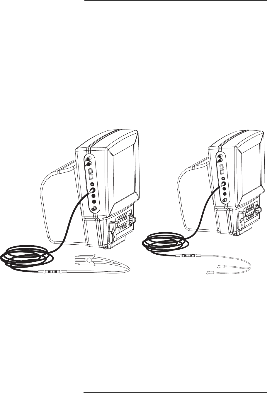
7 —3
7 —SpO
2
SpO
2
Monitoring Procedures
(Pulse Oximetry)
The following instructions describe procedures for preparing a patient
for SpO2 monitoring.
There are three SpO2 sensors available:
• Adult finger-toe clip
• Pediatric finger-toe clip
• Neonate probe
Shown below are two of these attached to a sensor extension cable.
The sensor is connected to the
Veris
monitor by means of an
extension cable. The sensor extension cable contains electrically
conductive material. Do not extend or coil the SpO2 sensor extension
cable into the magnet bore.
The monitor's SpO2 extension cable accepts only fiber optic sensors.
Figure 7-1: Sensor Connection for SpO
2
Adult Finger Probe Neonate Probe

MEDRAD
Veris
8600
7 —4
• The pulse oximeter sensor may cause skin irritation and
pressure necrosis. Inspect the pulse oximeter sensor site every
two to four hours or per hospital protocol. Move the sensor to a
different location if skin irritation is present.
• Excessive amounts of motion at the sensor sites may cause
errors in reading. Attempt a reading when motion has stopped,
or move the sensor to another site.
• The sensor extension cable contains electrically conductive
material. Do not coil or extend the sensor extension cable into
the magnet bore!
• To remove the SpO2 connector, grip the connector's retaining
ring (in the middle of the connector) and pull back gently. The
retaining ring slides back and unlocks the connector. Do not
attempt to unscrew.
Attaching the Probe
to the Monitor
1. Press the ON/OFF or STANDBY button to turn on the monitor.
2. Connect the SpO2 sensor extension cable to the monitor. Align
the red dot on the monitor’s SpO2 receptacle with the red dot on
the black SpO2 connector housing. Push the connector firmly
into the receptacle.
3. Select the appropriate probe and attach the probe to the patient
(refer to the next section). Attach the probe's connector to the
SpO2 sensor extension cable.
Attaching the Probe
to the Patient
Select the appropriate probe and application technique from the
following pictures and descriptions. The selected probe should be
cleaned before use.
• Attaching the probe too tightly to the skin may generate
inaccurate readings (by reducing blood flow to the target area)
and cause blisters on the patient's skin. (Lack of skin
respiration, not heat, causes the blisters.)
• The protection against the effects of electric shock of the Pulse
oximeter function is of type BF. This protection is contained in
the fiber optic sensor cable.
CAUTION
!!
CAUTION
!!

7 —5
7 —SpO
2
• Fiber optic sensors can be damaged if subjected to severe
stress, such as pulling, bending, or crushing. The sensor
(including the connector cable) should not be stepped on, jerked
or bent into a very tight arc (radius less than 2 inches). It is
recommended to use tape to strain-relieve the fiber optic cable
to the patient couch before attaching the sensor to the patient.
• Reposition the probe at least once every 24 hours to allow the
patient's skin to respire.
• Do not extend or coil the SpO2 sensor extension cable into the
magnet bore. There is a potential for thermal heating of the
extension cable, caused by the interaction between the MR
system’s RF energy and the electrically conductive sensor
extension cable.
• Use only oximeter probes supplied with, or specifically intended
for use with, the
Veris
8600 patient monitor.
• Significant levels of dysfunctional hemoglobins, such as
carboxyhemoglobin or methemoglobin, affects the accuracy of
the SpO2 measurement.
•SpO
2 measurement may be affected in the presence of high
ambient light. Shield the probe area (with a surgical towel, for
example) if necessary.
• Dyes introduced into the bloodstream, such as methylene blue,
indocyanine green, indigo carmine and fluorescein, may result
in inaccurate SpO2 readings.
• Any condition that restricts blood flow, such as use of a blood
pressure cuff or extremes in systemic vascular resistance, may
cause an inability to determine accurate pulse and SpO2
readings.
• The light source portion of the SpO2 sensor must be properly
positioned over the nail bed for the plethysmographic waveform
to appear.
• The SpO2 waveform display is not necessarilly directly
proportional to pulse volume. The SpO2 waveform display is not
automatically gain adjusted.
• Remove fingernail polish or false fingernails before applying
SpO2 probes. Fingernail polish or false fingernails may cause
inaccurate SpO2 readings.
CAUTION
!!

MEDRAD
Veris
8600
7 —6
Finger Probe Application
for Adults
1. Attach the finger probe to the patient as shown. Be sure to fully
insert the patient's finger into the probe. Run the fiber optic
cable away from the hand. For patients with long fingernails, use
the neonatal probe.
2. Apply the sensor with the light source positioned directly over
the nail-bed, and the detector over the fleshy portion of the
finger.
NOTES:
Do not tape over the pulse oximeter sensor housing. Taping
over the housing may cause injury and sensor failure due to
excessive pressure. If the sensor needs to be secured, place
tape over the cable, immediately behind the sensor.
The sensor must be properly positioned for a plethysmographic
waveform to appear. Placing tape too tightly around an extremity
reduces blood flow, thus diminishing the amplitude of the
plethysmographic waveform.
If possible, do not place the pulse oximeter sensor on the same
extremity as the blood pressure cuff or an arterial line. Place the
pulse oximeter sensor on the side of the patient opposite the
blood pressure cuff or an arterial line. The occlusion of the blood
flow during blood pressure determinations could affect
saturation readings.
The pulse oximeter sensor is light sensitive. Too much ambient
light makes it difficult for the system to provide accurate
readings. The system provides a high ambient light alarm
message when it is necessary to shield the sensor from
extraneous light sources such as phototherapy light or infrared
heating lamps.
Figure 7-2: Finger Sensor Placement
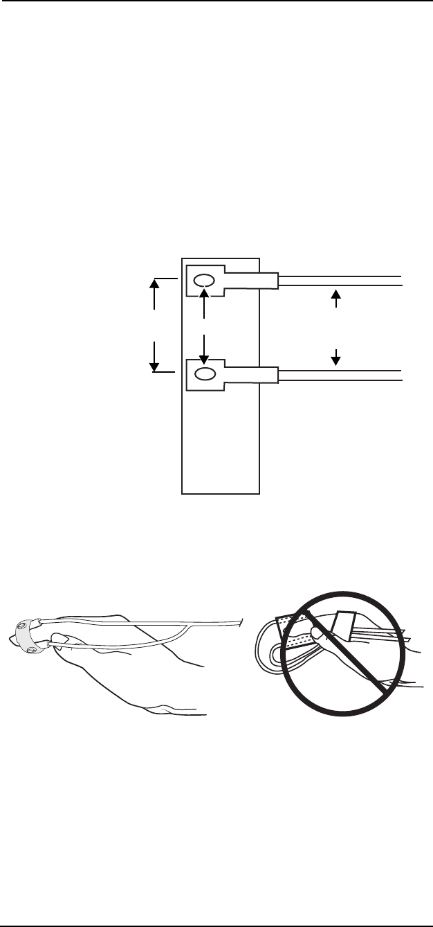
7 —7
7 —SpO
2
Neonate Probe Placement
In situations where a finger sensor is not practical, a MEDRAD
neonate probe can be used. The sensor pads are small, light-weight,
and adjustable.
The neonate probe can be placed using adhesive tape. Special care
should be taken not to restrict blood flow in the finger tip.
TAPE PREPARATION OF NEONATE PROBE
Attach the two sides of the neonate probe to a pre punched neonate
tape strip as shown in “Figure 7-3: Tape Prep for Neonate Probe
Placement”. Select either the standard or small separation as
appropriate. When using the neonate probe on a toe, it can be helpful
to cut the tape strip along the length.
Figure 7-3: Tape Prep for Neonate Probe Placement
FINGER
NOTE: Proper application of the neonate probe on the finger is
essential. See “Figure 7-4: Neonate Probe Finger Placement”
Figure 7-4: Neonate Probe Finger Placement
1. Attach the neonate probe to a pre punched neonate tape strip
as shown in “Figure 7-3: Tape Prep for Neonate Probe
Placement”. Select either the standard or small separation as
appropriate.
Windows Fibers
Optic
Cables
Light Source Side
Detector Side
1.5”
(3.8cm)
Correct Incorrect
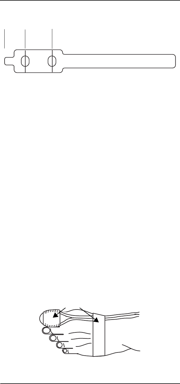
MEDRAD
Veris
8600
7 —8
2. Remove the backing from the light source side of the neonate
tape.
Figure 7-5: Neonate Probe Tape
3. Attach the neonate probe to the patient with the light source
side to the fingernail.
4. Remove the backing from the center section of the neonate
tape. See “Figure 7-5: Neonate Probe Tape” on page 7-8.
5. Line up the light source side with the detector side so the source
and detector are in the same plane.
NOTE: The fiber optic cables run along the finger toward the
wrist.
6. Remove the backing from the remaining portion of the tape and
secure the probe and cable. Do not to over-tighten the tape.
TOE
1. Attach the neonate probe to a pre punched neonate tape strip.
2. Remove the backing from the light source side of the neonate
tape. See “Figure 7-5: Neonate Probe Tape” on page 7-8.
3. Attach the probe to the patient's toe as shown with the light
source side on the toenail.
NOTE: The fiber optic cables run along the foot toward the heel.
4. Remove the backing from the center section of the neonate
tape. See “Figure 7-5: Neonate Probe Tape” on page 7-8.
5. Line up the light source with the detector side so the source and
detector are in the same plane.
6. Remove the backing from the remaining portion of the tape and
secure the sensor and cable with neonate tape being careful not
to over-tighten the tape.
Figure 7-6: Neonate Probe Toe Placement
Light
Source
Side Center
Section
Neonate Tape Strips

7 —9
7 —SpO
2
FOOT (INFANTS)
1. Attach the neonate probe to a neonate tape strip.
2. Remove the backing from the light source side of the neonate
tape. See “Figure 7-5: Neonate Probe Tape” on page 7-8.
3. Attach the neonate probe to the infant's foot as shown in “Figure
7-7: Neonate Probe Foot Placement (Infants)”, just behind the
small toe. Attach the sensor with the light source side on the top
or outside of the foot to keep the detector side away from
ambient light.
4. Remove the backing from the center section of the neonate
tape. See “Figure 7-5: Neonate Probe Tape” on page 7-8.
5. Line up the light source side with the detector side, so the
source and detector are in the same plane.
6. Remove the backing from the remaining portion of the tape and
secure the neonate probe with neonate tape, being careful not
to over-tighten the tape.
Figure 7-7: Neonate Probe Foot Placement (Infants)
Light Source
(Top of Foot)
Detector Neonate
Tape Strip

MEDRAD
Veris
8600
7 —10
SpO
2
Peripheral Gating
Peripheral (SpO2) gating provides an alternative to ECG gating. (See
“Gating Interface” on page 5-18.) It utilizes the signal obtained from
the pulse oximeter sensor.
Figure 7-8: SpO
2
Peripheral Gating Connection
The pulse oximeter signal is obtained from the patient and displayed
on the monitor. To utilize the peripheral gating function on the monitor
a cable is attached to the GATING connector of the monitor with the
distal end connected to the SpO2 receptacle of the MR scanner.
NOTE: Gating cables are scanner specific. If a specific cable does
not exist for your particular scanner, the universal cable may be used.
The source of the gating signal may arise from the ECG or SpO2. The
gating signal from either of these sources may be delivered to the
scanner in two user-selectable forms—waveform or pulse.
•Waveform output: one of the following: 1mV ECG waveform or
a plethysmogram (SpO2) waveform.
•Pulse output: 1mV pulse amplitude and 50 msec pulse width,
synchronous with the r-wave or corresponding peak of the
plethysmogram (SpO2) waveform.
The delay time from detection of the SpO2 signal at the patient to the
input of the MR scanner is less than or equal to 20 milliseconds.

MEDRAD
Veris
8600
7 —11
One of two icons appears in the upper left corner of the heart rate
numerical display box. These icons represent the gating signal
output—either waveform or pulse. The icon is the same color as the
SpO2 waveform color when SpO2 is selected for gating.
The gating function is user-selectable: OFF, ECG Waveform, ECG
Pulse, SpO2 Waveform, or SpO2 Pulse. The default is OFF.
1. Connect the cable appropriate for the scanner to the GATING
connection on the
Veris
patient monitor.
NOTE: The gating cable must be IEC 950 or IEC 60950
compliant.
2. Connect the MR scanner end of the cable to the scanner
interface receptacle.
NOTES:
To remove the gating cable, grip the cable connectors from both
ends and pull back firmly. Do not pull on the gating cable to
remove it from the monitor or scanner.
Inspect the gating cable and connections regularly for signs of
mechanical damage (e.g., cracked insulation, crimped, or bent
wires).
3. With the menu knob select the PARAMS menu.
4. At Gating select either SpO2 Wave or SpO2 Pulse.
5. Configure the scanner in accordance with the manufacturer’s
recommendations.
Waveform Output
Pulse Output

8 —1
8 — IBP
Theory of Operation
The IBP monitoring module is intended for direct pressure monitoring
using an intra-arterial catheter, a continuous flushing system, and an
IBP transducer. The IBP module provides analog to digital conversion
of the transducer signal.
The IBP module processes continuous digital patient data that can be
displayed as waveform and numerical values. The module supports
up to two separate IBP channels simultaneously. For arterial and
pulmonary artery IBP measurements the numerical values for
systolic, diastolic, and mean pressure are computed and displayed.
Heart Rate
The IBP pulse rate is used if the ECG pulse rate data is unavailable.
See “Heart Rate” on page 5-1 for more information.
Method of Measurement
The IBP module uses standard invasive pressure monitoring
techniques. A bridge transducer is measured by a highly accurate
analog to digital converter. The measuring circuit uses a 5 volt
excitation voltage that provides a transfer function of 25 micro-volts
per mmHg of pressure.
The signal is buffered and brought to the A/D converter, which is
configured for a full scale signal of ±25 millivolts. The circuit has a
potential measuring range of ±1000 mmHg of pressure. This range is
restricted to -20 to +300 mmHg for actual monitoring purposes.
There is no analog amplification of the transducer signal.
The module uses a rate of 50 samples per second for each of the two
independent IBP channels. The resulting measurement resolution is
slightly less than 0.5 mmHg. The numerical IBP value is reported by
the 8600 monitor at a resolution of 1 mmHg.
Non-pulsatile IBP sites (LA, RA, CVP, or ICP) are reported as mean
numerical values. The non-pulsatile mean value is an average of the
last 200 samples taken over a period of approximately 4 seconds.
The values for pulsatile sites (ART, PA, RV, and LV) are reported as
an average of the last eight calculated values.
The IBP heart rate is reported as an average of the last 16 heart rate
values. The software also scans for sudden changes in heart rate and
overrides the averaging function when the condition occurs.
IBP Clinical Testing
and Accuracy
The invasive blood pressure module is in compliance with applied
standard IEC 60601-2-34 and has been tested to meet the
performance specifications listed in this manual. The module as
installed in the
Veris
monitor has been clinically tested for
performance with a variety of patients and specific disposable
invasive blood pressure transducers.
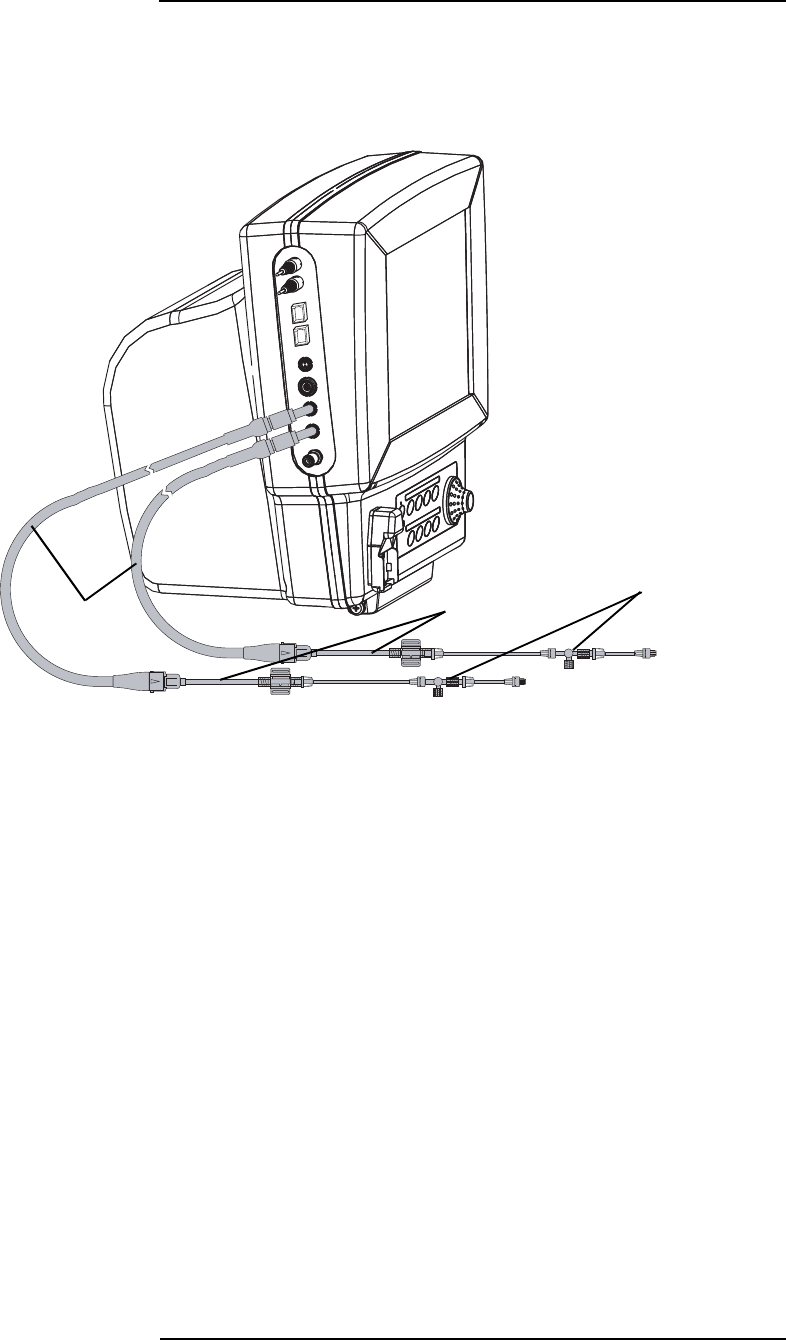
MEDRAD
Veris
8600
8 —2
IBP Monitoring
Invasive Blood Pressure (IBP) allows monitoring of Real-Time
Invasive Blood Pressure with the use of a Blood Pressure Transducer.
The transducer converts the hydrostatic signals into electrical signals
which are displayed graphically on the monitor.
Figure 8-1: IBP Cable Connections with Interface Cables, Patient Connections
IBP
Interface
Cables
Transducers
Disposable
Intravenous
Sets

8 —3
8 —IBP
Invasive Blood Pressure
Transducers and Interface
Cables
As for all accessories, cables and transducers should comply with UL
and IEC standards for medical equipment. Use only pressure
transducers which have been recommended by MEDRAD. Please
note that MEDRAD does not sell or distribute transducers. The
following are examples of disposable transducers which meet the
Medrad specification of an electrical cable that does not exceed 14
inches in length:
• Abbott Transpac IV (REF 42582-05)
• B. Braun Combitrans (REF 5202620)
• Edwards/Baxter Truwave (REF PX600F & PX260)
• Medex Transtar (REF MX950)
• Use transducers whose electrical cable length does not exceed
14 inches. Failure to follow this instruction could produce a
patient burn or shock hazard resulting in serious injury or death.
IBP Interface Cable
There are 4 IBP interface cables. Each one is specific for a particular
transducer. The cables can be connected to the monitor through IBP1
(Port Channel 1), IBP2 (Port Channel 2), or both.
Transducer specifications and the interface cable which fits each
specific type are listed in Appendix F: "IBP Transducer
Specifications”.
• Failure to follow proper invasive blood pressure monitoring and
insertion techniques may cause clots leading to cerebral or
pulmonary embolism resulting in serious patient injury or death.
Follow all manufacturer’s instructions and precautions provided
with the transducer and intra-arterial catheter.
• Do not coil or extend the IBP interface cable in the magnet bore.
This could result in patient shock or burn. All cables must be
straight, not coiled, and routed down the center of the scanner
table.
• Use transducers with an electrical cable length of 14” or less.
WARNING
!!
WARNING
!!

MEDRAD
Veris
8600
8 —4
• Do not place the IBP transducer in the bore of the magnet. This
could result in degraded measurement accuracy. Ensure the
transducer is outside of the magnet bore.
• Place only the disposable tubing portion of the IBP kit in the
magnet bore to ensure patient safety and improve measurement
accuracy. Use a disposable set which is a minimum of four feet
(1219 mm) in length.
• Calibrate (zero), the transducer when changing or modifying
transducer tubing.
• When changing or modifying a transducer tubing set, ensure
that the entire fluid path is free of air bubbles. Do not allow air
bubbles to enter the the catheter.
CAUTION
!!

8 —5
8 —IBP
IBP Monitoring Procedure
The following instructions describe procedures for preparing a patient
for invasive blood pressure monitoring. We recommend IBP
transducers that have a required specification of 5 microvolts/mmHg.
and the frequency response at 20 hertz. There are several to choose
from.
Each IBP channel has its own dedicated IBP port that is located on
the side of the monitor.
Figure 8-2: IBP Ports
The IBP ports are customized 5-pin female sockets and are designed
to accept only MEDRAD compatible IBP interface cables.
The transducer specifications and information for obtaining
transducer cables is located in Appendix F: "IBP Transducer
Specifications” of this manual.
IBP Port Channel 1
IBP Port Channel 2

MEDRAD
Veris
8600
8 —6
IBP Safety
• Do not extend the distal portion of the transducer with the micro-
chip into the bore of the magnet.
• The accuracy of invasive blood pressure readings may be
adversely affected when used on patients with intra-aortic
balloon pumps.
• For accurate performance, IBP transducers must conform with
the specification designated by MEDRAD, Inc. Follow the
instructions provided with your transducer.
• Accuracy of the IBP measurement can be affected by poor
setup of the transducer or fluid system. Follow hospital protocols
for invasive blood pressure monitoring.
• Possible shock hazard. Avoid using metal components in IBP
fluid systems.
Setup and User Calibration
The IBP monitoring system requires the clinician to periodically
calibrate the monitor. The air vent stopcock of the transducer is
opened and the transducer is exposed to the ambient room pressure.
The monitor reads the transducer signal and makes adjustments to
compensate for small changes in the transducer and/or ambient
pressure.
This operation is described as having “zeroed” the IBP monitor. Each
time a new IBP site is setup, the clinician must zero that channel. The
channels may be zeroed together or independently.
Although waveforms are always present, the monitor does not show
numerical values until the monitor is zeroed. While the monitor
calibrates, it is possible to observe the correction of the waveform.
The monitor must be zeroed when:
• The monitor is powered up.
• The transducer is changed or the cable is re-inserted.
• The patient size is changed; Adult, Pediatric, or Neonatal Mode.
It is recommended that the IBP channels be zeroed at least every 8
hours when sustained IBP monitoring is necessary.
To zero the IBP channels for monitoring:
1. Setup the IBP fluid system and transducer according to hospital
protocols.
2. Verify that the correct alarm limits are entered into the ALARMS
window of the monitor.
WARNING
!!
CAUTION
!!

8 —7
8 —IBP
3. Connect the IBP interface cable to the
Veris
monitor.
4. Connect the appropriate IBP interface cable to the transducer.
5. The monitor displays the message NOT ZEROED in the
informational alarm line. The message appears independently
for each channel.
NOTE: If a waveform slot is set to display IBP, the monitor
shows a waveform immediately. This waveform is representative
of the physiological patient data, but is not yet scaled until the
IBP lines are properly zeroed. No numerical values are
displayed for a channel until it has been zeroed.
6. Select PARAMS and open the first window of parameters.
Figure 8-3: Setting IBP in the PARAMS Window
NOTE: The example window shown contains factory default
values. Reset the parameters as required for actual monitoring
conditions.
7. Verify that the channels are set to the correct IBP sites.
8. Verify that the pressure range is set correctly.
EXIT
HR Source Smart
Gating OFF
ECG ON
Cable 5 lead
Filter Monitor
Display Range MEDIUM
Auto lead switching YES
Color ¤
IBP 1 SITE ART RANGE 0 TO 200 ZERO None Color ¤
IBP 2 SITE CVP RANGE 0 TO 20 ZERO None Color ¤
NIBP ON GASES ON
NIBP tone NONE
Color ¤
ECG/IBP/SPO2 Tone Vol 5
Other Params Menus No Action

MEDRAD
Veris
8600
8 —8
9. Set the transducer to the zero calibration position. Generally this
requires opening a stopcock on the transducer to allow an
ambient room pressure reading. Follow the directions for your
transducer.
10.Go to the PARAMS window by selecting and pressing the
PARAMS softkey with the menu knob.
11.Go to the IBP 1 or IBP 2 parameters. Move the cursor to the
ZERO selection item in the PARAMS window. Set ZERO to One
to begin zero calibration.
NOTE: The ZERO setting can be changed to All to begin zero
calibration of both IBP channels at the same time. The stopcock
must be open on each transducer to be zeroed.
12.When you zero the channel, numerical values appear in the IBP
box in the lower right corner of the main display. The message
ZERO GOOD briefly appears.
13.Exit the PARAMS window.
14.Return the transducer to its normal monitoring position. The
numerical values for pulsatile IBP sites appears and displayed
IBP waveforms resume their normal shape.
NOTE: the monitor cannot calibrate to a zero offset that exceeds
± 150 mmHg. The monitor reports a ZERO FAIL message. Contact
MEDRAD Service or your local representative if you cannot zero the
monitor.
NOTE: According to information I found and conversion used: at an
elevation of 2,000 meters (6,561.7 ft.) the transducer will not
calibrate.
Zero Calibration (Quick)
You can quickly zero the IBP channels using the softkeys on the main
menu.
1. Open the transducers to atmosphere pressure.
2. Turn the menu knob to highlight
ZERO
IBP1 (or
ZERO
IBP2) from
the main menu.
3. Press in the menu knob to begin the zero calibration of the
selected IBP channel.
4. Wait until the message ZERO GOOD appears in the alarms
message area.
5. Close the transducers.

MEDRAD
Veris
8600
8 —9
Clinical Use and
Arterial Waveforms
A variety of physiological conditions alters the appearance of the IBP
pressure waveforms. Conditions such as hypertension, shock,
obstruction of the aorta, aortic valve disease, and pericarditis can
affect the arterial pressure waveform.
The arterial waveforms may also be affected by poor setup. The more
common problems affecting arterial waveforms are overdamping,
catheter whip and lack of periodic calibration.
Overdamping is caused by air bubbles, thrombus formation at the tip
of the catheter, or lodging of the catheter tip against the vessel wall.
Overdamping exhibits itself as a poorly defined waveform without a
noticeable dicrotic notch.
Catheter whip is caused by excessive movement of the catheter tip
within the vessel. Catheter whip exhibits itself as an erratic or noisy
waveform.
As described above, zero the IBP channels at least every eight hours
or according to hospital protocol.
Disparity between invasive and non-invasive blood pressure values
normally occurs due to the difference in the measurement technique.
Cuff pressure (NIBP) tends to be 5 to 10 mmHg lower than invasive
(IBP) measurements. This disparity can be even more pronounced in
hypothermic patients and with poorly arranged IBP tubing.
NOTE: Position transducers at the same height as the patient’s heart
for optimal measurement accuracy.

9 —1
9 — Temperature
Theory of Operation
The
Veris
monitor uses a fiber-optic thermometer to measure
temperature. This provides accurate and reliable measurements in
the MRI environment.
This sensor probe features an environmentally inert, non-conductive,
non-metallic, miniature probe, making it ideal for harsh operating
conditions like the MRI environment, which includes conditions where
high levels of electromagnetic interference (EMI) such as RF field or
high voltages exist. The probe itself is inert to chemical and biological
agents and is ideally suited to applications where a completely non-
reactive sensor is required or where other types of sensors would
malfunction or become damaged.
Figure 9: Temperature Probe Signals
The temperature system is comprised of a probe, a fiber optic cable,
and the optoelectronic sensor head containing detection optics,
signal processing, and interfaces. The probe itself contains a
patented, highly temperature-sensitive phosphor as its sensing
element, and both the probe and phosphor are protected by a
fluoropolymer sheath. The standard cable length is 3 meters.
The temperature system uses a fluorodecay sensing technique.
Pulsed light from an LED is sent down the optical fiber to energize the
phosphor. The time decaying glow of the phosphor changes with
temperature and is transmitted back to the sensor head where it is
converted to a temperature reading. The temperature system uses a
unique ratio measurement system to minimize inaccuracies due to
signal loss from the fiber and connector.
The temperature system is fully calibrated at the factory.
Temperature-sensitive
Phosphor
Optical Fiber
Time-decaying phosphor
emission pulse returns to
detection circuitry
Incident pulse of LED
energizes phosphor;
spontaneous emission
occurs
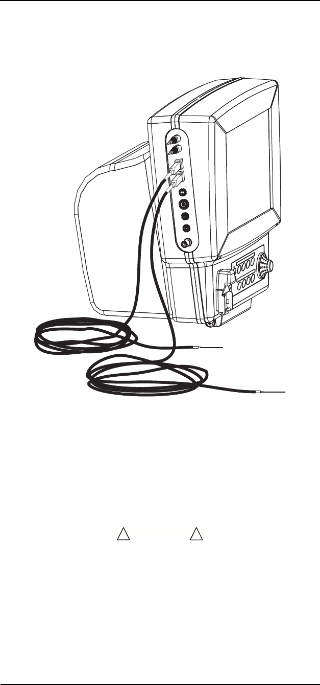
MEDRAD
Veris
8600
9 —2
Temperature Monitoring
Procedures
The
Veris
monitor system provides for two temperature probes,
allowing for patient temperature measurements from two different
locations. The user is not required to use both probes simultaneously
nor is one probe dominant over the other.
Figure 9-1: Temperature Probe Connection
Skin surface temperature monitoring is intended for the detection of
hypothermic and hyperthermic conditions. The skin temperature
sensor is designed for placement on the surface of the skin only.
To insure the proper performance of the temperature accessories,
follow the precautions listed below.
• Skin abrasion and tissue burn hazard! Separate the monitor and
temperature cables from electrocautery systems; keep both
active and ground electrodes of the electrocautery system in
close proximity so that the temperature sensor is outside the
radio-frequency current field.
WARNING
!!

9 —3
9 —Temperature
• Forced mating of the connectors without proper alignment may
cause damage to the connectors and interruption in electrical
continuity and optical alignment.
• During use, do not entwine the cable with other electrical
cables.
• To remove the temperature connector, press on the locking clip
and pull straight out. Do not pull on the temperature sensor
cable to remove the temperature connector from the monitor.
• Fiber optic sensors can be damaged if subjected to severe
stress, such as pulling, bending, or crushing. The sensor
(including the connector cable) should not be stepped on,
jerked, or bent into a very tight arc (radius less than 1 cm). It is
recommended to use tape to strain relieve the fiber optic cable
to the patient couch before attaching the sensor to the patient.
• Reposition the probe at least once every 24 hours to allow the
patient's skin to respire.
CAUTION
!!

MEDRAD
Veris
8600
9 —4
Directions for Use with
Skin Surface Probe
Preparing the Equipment
1. Press the ON/OFF or STANDBY button to turn on the monitor.
Check the monitor settings for the correct setup.
2. Connect the temperature probes to the monitor.
NOTE: Take care to align the temperature sensor plug so that
the locking clip on the plug lines up correctly with the receptacle
on the side of the monitor. Forced mating of the connectors
without proper alignment may cause damage to the connectors
and interruption in electrical continuity.
NOTE: The monitor’s temperature connection accepts any
MEDRAD fiber-optic temperature accessory.
3. Unwind the cable from the protective card and peel the sensor
from the card.
Attaching the Temperature Probe
to the Patient
MEDRAD recommends attaching the temperature probes at either
the Axillary or Femoral location as shown in “Figure 9-2: Temperature
Probe Locations” below.
Figure 9-2: Temperature Probe Locations
4. Prepare the skin site according to established protocol. Prepare
the patient by ensuring that any hair is removed from the
location(s) where you intend to place the temperature probe(s).
5. Adhere the sensor to the skin site. Apply tape length-wise along
the cable, directly over the flouroptic sensor as well as to the
cable sheath.
Axillary
Femoral

10 —1
10 — Anesthetic Agents
Theory of Operations
Integrated CO
2
and Agent
Gas Detector
The integrated detector measures carbon dioxide (CO
2
), nitrous oxide
(N
2
O), and five halogenated anesthetic agent gases using the same
sample collection path and testing apparatus. The analyzer uses
proprietary High IQ™ technology to identify and quantify agent
gases. There are no moving parts, reducing size of the detector and
enhancing reliability.
The
Veris
monitor uses the sidestream method of measuring CO
2
and
anesthetic agent gases. Gas is drawn through a nasal cannula or
sample line. The gas sample enters the monitor from a sampling tube
into a water trap, which removes water vapor and particulate matter
from the gas sample. The gas then enters the CO
2
(agent) detector
where it is analyzed.
Agent Gas Measurement
The agent detector samples gas breathed by the patient through a
sidestream circuit. It measures the concentrations of CO
2
, N
2
O, and
halogenated anesthetic agents in the sampled gas. The detector
uses far-infrared measurements to identify concentrations of
halothane, enflurane, isoflurane, sevoflurane, desflurane anesthetic
agents and their mixtures.
The analyzer uses the principles of infrared absorption spectrometry
to measure anesthetic gases. The integrated detector determines the
concentrations of anesthetic gases and CO
2
by measuring the optical
absorption of the sampled patient gas at a number of specific
wavelengths in the medium to long-wave infrared region.
AGENT ACCURACY OF MEASUREMENT
The accuracy of a single agent measurement is defined by the
formula,
where “m” is equal to the measurement in percent and “x” is the
tolerance range.
Example of 5% HAL measurement, calculating the high limit of the
tolerance range.
(5% HAL × 0.04Reading) + 0.1%Absolute = 0.3%
5% HAL + 0.3%Tolerance = 5.3%
Final tolerance range is 4.7% to 5.3% HAL.
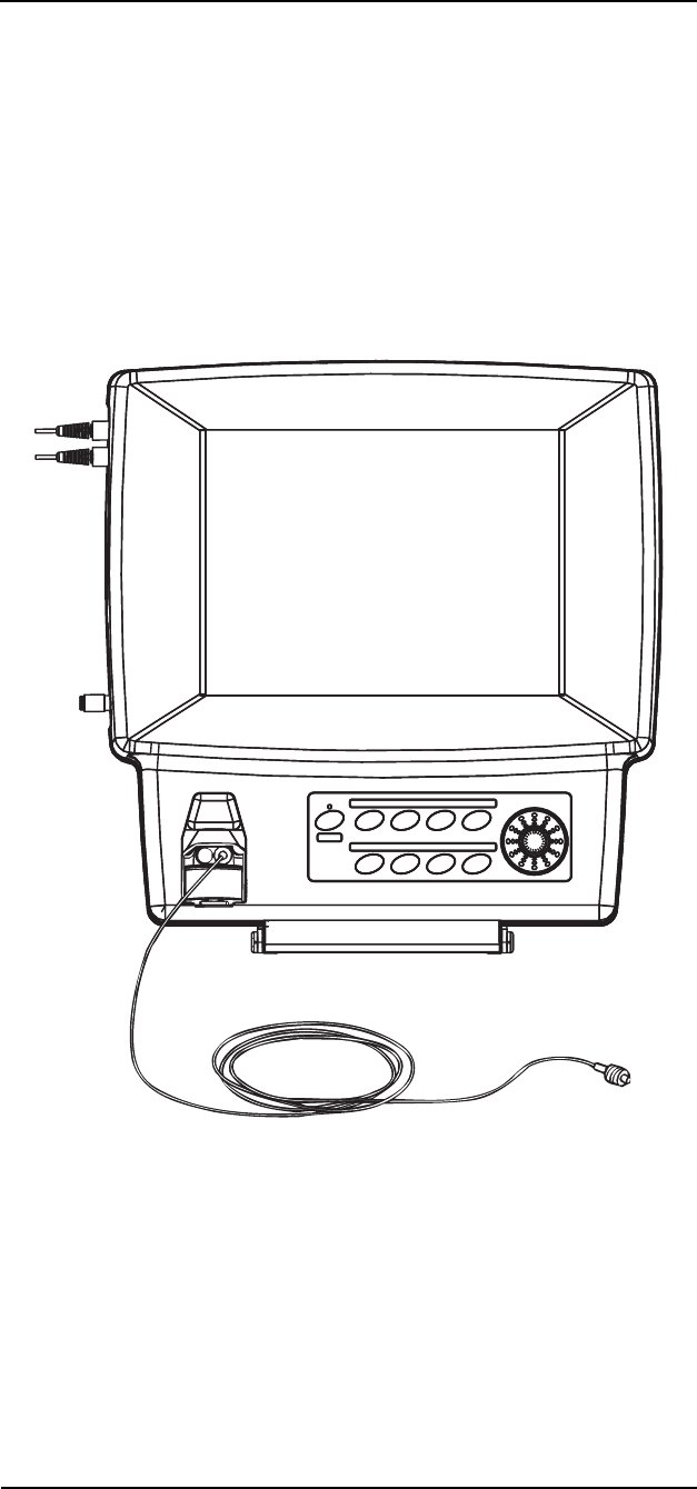
MEDRAD
Veris
8600
10 —2
Gas Monitoring Procedures
The following instructions describe procedures for preparing a patient
for CO
2
, O
2
, N
2
O, and agent (AGT) monitoring.
Sampling Circuit Connections
The monitor uses a sidestream gas sampling circuit composed of a
water trap, a sampling line and a sampling device. The water trap is a
combination filter and moisture condenser. The same circuit is used
for CO
2
, O
2
, N
2
O, and agent monitoring.
Shown below is the patient monitor with a water trap and sample line
connection. Please refer to “Accessories” in Appendix D for part
numbers.
Figure 10-1: Gas Sampling Connection
The monitor’s gas sampling connection (from the water trap) accepts
gas sampling lines using the Luer style connections. It is important to
use the recommended water trap and combinations in order to
provide the correct flow rates for monitoring purposes.

10 —3
10 —Anesthetic Agents
Gas Monitoring Safety
The following instructions describe precautions and contraindications
for gas monitoring. Use all safety procedures and protocols for
anesthetic safety as designated by your health care facility.
• Do not use this monitoring system in conjunction with highly
flammable anesthetics such as cyclopropane or ether.
• The monitoring system is not intended for monitoring gas
mixtures containing methoxyflurane or halogenated
hydrocarbons not specifically listed as a monitored gas.
• Environmental pollution of nitrous oxide and halogenated
agents may cause accuracy errors. Always use anesthetic gas
scavenging systems (AGSS) with the monitoring system.
• Infectious agents may be transferred between patients through
the return of the monitor's exhaust to the patient's breathing
circuit.
• Infectious agents may be transferred between patients through
contaminated masks and nasal cannulas. Change the sample
devise and sampling line before use with each new patient.
• Never attach intravenous tubes to gas sampling connections.
Gas sampling lines may be inadvertently connected to
intravascular fluid systems; allowing air into a blood vessel.
• Use MEDRAD MRI compliant supplied gas cylinders only for
verification of gas readings. They are suitable for use in the MRI
environment. See “Accessories” in Appendix D for part
numbers.
• Use only MEDRAD water traps with this monitor.
• Care should be taken to prevent gas tubing from being
obstructed in any way by the scanner table or other equipment.
• Change sample lines and sampling devices between each
patient. Infectious agents may be transmitted through reuse of
sampling lines.
• Do not connect the monitor’s exhaust for return flow to the
breathing circuit. Infectious agents may be transmitted through
reverse flow from sampling devices.
• Use of longer sampling lines or extensions increases the
monitor’s response time and can affect accuracy.
WARNING
!!
CAUTION
!!

MEDRAD
Veris
8600
10 —4
Water Trap
The water trap has a connection located at the top that fits up and
into the gas receptacle of the monitor.
Figure 10-2: WaterChek
™
2
+
Water Trap
The trap slides out of the front receptacle and can be quickly replaced
if it becomes filled or occluded. The front of the WaterChek™
2+ water
trap has a female Luer-lock sampling line entrance.
Luer-lock entrance
Slide up and into
receptacle
Water Trap
Water Trap Receptacle
(On Monitor)
Water Trap
Connection

10 —5
10 —Anesthetic Agents
Sampling Devices
Shown below is a typical gas sampling device (nasal cannula)
attached to a sample line. This nasal cannula is used for both CO
2
,
O
2
, N
2
O, and agent (AGT) monitoring.
Figure 10-3: Nasal Cannula
If using the nasal cannula, position it directly under the patient's nose
with the prongs extending into the nostrils. Slide the adjuster forward
to close the loop around the head.
The nasal cannula is intended for single patient use only. Alternate
sampling devices such as masks may be used if they have a female
Luer-locking sampling entrance. Intubation breathing circuits require
a sampling entrance near the connection to the endotracheal tube.
The divided nasal cannula delivers O
2
and samples for CO
2
.
Intubated Patients
The monitor can be used with intubated patients. Use recommended
water traps and breath circuit adaptors. Check the trap reservoirs
regularly. Check the breath circuit regularly for leaks or
disconnections. Follow the directions provided with your endotracheal
tube for additional precautions.
• Additional adaptors between the endotracheal tube and the
sampling entrance should not exceed five centimeters.
CAUTION
!!
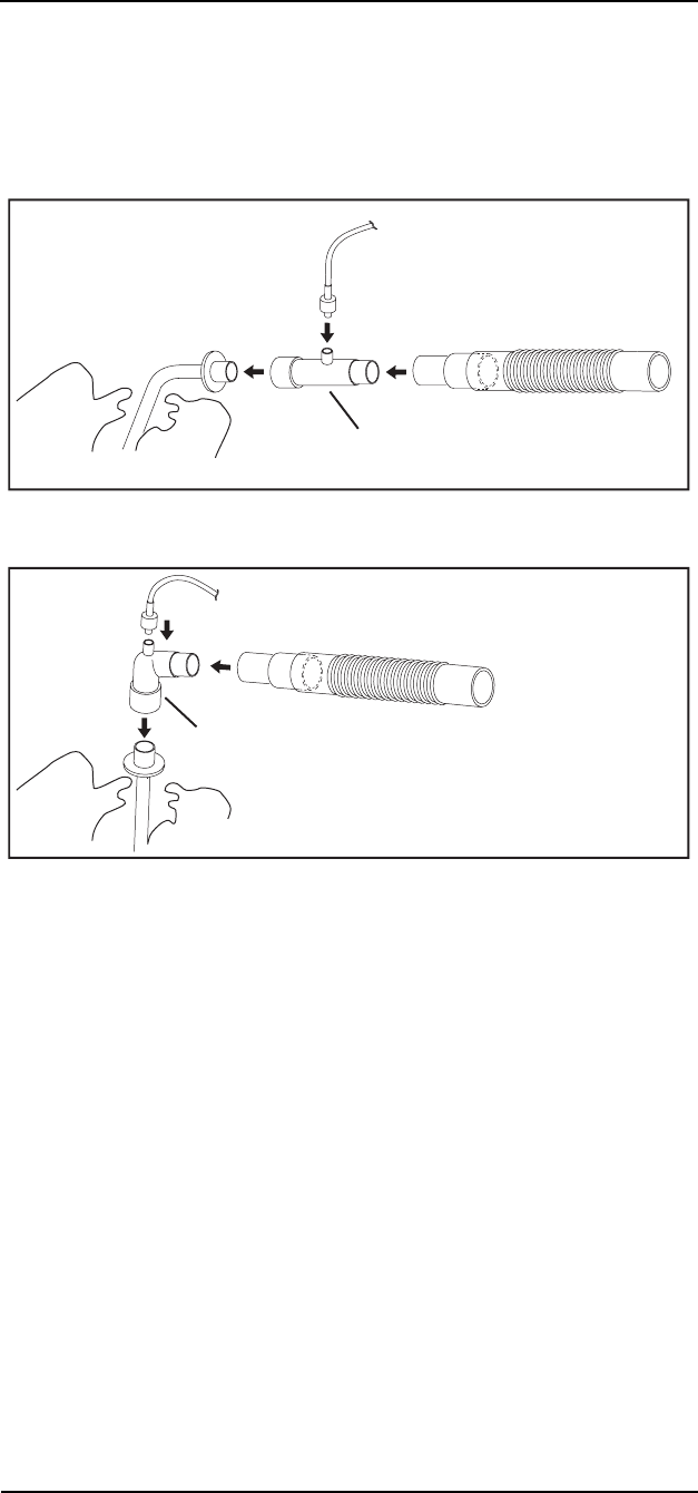
MEDRAD
Veris
8600
10 —6
Standard breath circuit configurations are shown below beginning
with a common endotracheal tube with a 15mm outside diameter. The
circuit then extends to meet a standard 22mm inside diameter
ventilation flex tube. Confirm the proper fit of all breath circuit
components before attempting patient monitoring.
Figure 10-4: Straight Ventilation Adaptor Setup
Figure 10-5: Elbow Ventilation Adaptor Setup
Calibration and Startup
The monitor automatically begins an auto-calibration sequence when
powered up. During this time the monitor may display a flat
capnogram for approximately ten seconds. When the calibration and
warm up sequence is over the system messages disappear and
normal operation begins.
22mm I.D. Ventilation Tube
with 15mm I.D. Adaptor
Sampling Line (Luer-lock)
15mm I.D./15mm O.D.
Ventilation Adaptor with
Luer-lock Sampling Entrance
Endotracheal
Tube 15mm O.D.
22mm I.D. Ventilation Tube
with 15mm I.D. Adaptor
Sampling Line
(Luer-lock)
15mm I.D./15mm O.D.
Elbow Adaptor with
Luer-lock Sampling Entrance
Endotracheal Tube 15mm O.D.

MEDRAD
Veris
8600
10 —7
Procedure for Gas Monitoring
1. Check the Flow Rate settings in the PARAMS softkey window.
2. Slide the WaterChek
™
water trap into the gas receptacle of the
monitor.
3. If anesthetic agents are being used, attach a scavenging line to
the exhaust port at the pedestal of the monitor. A waste gas
recovery system should be used.
4. Attach a sample line to the Luer fixture located on the front of
the WaterChek
™
water trap.
5. Make sure the sampling line is not kinked or pinched.
6. Attach a patient sampling device to the sampling line. Use either
a nasal cannula, mask or ventilation tube adapter.
7. Replace sampling devices, lines, and water traps if they become
blocked or filled.
Occlusions
The monitor displays a visual message AGT: OCCLUSION if the gas
sampling system is blocked. If the sampling line or water trap
becomes partially blocked, the item should be replaced.
Anesthetic Gas
Exhaust Recovery
Always use an exhaust gas recovery system when using anesthetic
gasses. A scavenging kit can be used to connect the monitor to a gas
scavenging system.
1. Slide the tube over the nozzle of the exhaust port located on the
back of the monitor base, near the DC power cord.
2. Connect female Luer-lock end to an exhaust recovery system.
A straight adaptor 19mm O.D./19mm I.D. with a male Luer-lock
entrance is provided with the scavenging kit to provide a connection
to scavenging tubing.
The monitor displays AGT: NO EXHAUST if the scavenging line is
blocked.

11 —1
11 — CO
2
, O
2
, and N
2
O
Theory of Operation
Respiration
Respiration is measured via the CO
2
monitoring module and is only
available in Anesthesia models.
Capnometry
(Measurement of CO
2
)
The
Veris
monitor measures CO
2
concentrations and sends data
suitable for a continuous waveform display. The monitor also detects
end-tidal and fractional Inspired CO
2
levels and displays the
numerical values. End-tidal CO
2
(EtCO
2
) is defined as the maximum
CO
2
concentration at the end of expiration. The monitor measures the
CO
2
concentration and displays the numerical value. The EtCO
2
value is updated continuously with each breath cycle. The amount of
CO
2
in the gas mixture inhaled by the patient is the fractional Inspired
CO
2
(FICO
2
).
The monitor measures CO
2
using the principles of infrared absorption
spectrometry. An unknown concentration of gas (CO
2
) is calculated
by comparing its absorption of infrared light to that of a known
standard. The absorption of light is directly related to the
concentration of the gas. As infrared light passes through the sample
gas chamber, the light transmitted is converted to a voltage signal.
The monitor converts the voltage into CO
2
concentration data that
can be expressed numerically or as waveforms. The Beer's Law
calculation is performed by the software of the
Veris
monitor.
Infrared analysis of the gas samples is done using Beer’s Law. The
formula for Beer’s Law is as follows:
Infrared value of measured sample.
Infrared value of light source.
Exponential function.
Extinction coefficient.
Concentration of the gas sample
Distance measured through the sample
CONDITIONS OF USE
The
Veris
monitor has been calibrated with dry NIST-traceable
calibration gases at room temperature and pressure (~ 21C, 740
mmHg). Given the small effect of water vapor on agent gas and CO
2
measurements and the monitor’s built-in temperature and pressure
measurements and compensations, this method of gas analysis per
EN 864 is best described as ATPS (Ambient Temperature and
Pressure, Saturated; 21C, 750mmHg, 100% Humidity Saturated).
II
0e
ελ
()
cd
–
=
I
I0
e
ελ
()
c
d

MEDRAD
Veris
8600
11 —2
The
Veris
monitor is suitable for sustained pressure (breathing circuit)
monitoring environments and has been tested per Clause 102
(Sustained Pressure) of EN 864.
STABILITY OF ACCURACY
The monitor has an internal barometer and thermistor that allow
compensation for changes over a range of temperature and
atmospheric pressures. The monitor complies with EN 864 standards
for cyclical pressure. The module as installed in the
Veris
monitor has
been clinically tested for performance with a variety of patients.
Measuring Oxygen (O
2
)
The
Veris
monitor uses the sidestream method of measuring O
2
. The
gas is sampled from the same gas intake system used in CO
2
monitoring. The water trap removes moisture and particulate matter
from the gas samples.
METHOD
The gas sample is measured using a reactive oxygen cell. The
oxygen sensor is a galvanic electrochemical cell that works by a
process known as “oxidation reduction.”
Oxygen from the air comes in contact with a highly reactive metal,
reacts with the metal and produces a current. As the oxygen reacts,
this reactive metal is gradually being used up. Once the metal is used
up, the cell is depleted and can no longer sense oxygen.
The cell generates a voltage output proportional to the amount of
oxygen in the sampled gas. This oxygen cell has an internal
thermistor and circuitry that adjusts the output voltage based on
current temperature of the cell.
The voltage is read by the microprocessor and an O
2
measurement is
generated using predictive circuitry. This predictive function
enhances response time of the O
2
monitoring module.
The relationship between gas concentration and pressure is
calculated by the microprocessor. The numerical value displayed by
the monitor (O
2
Calculated) is generated using the following formula.
The measured O
2
predictive value is multiplied by a fixed value
derived from room pressure divided by room ambient oxygen levels.
The measurement is further adjusted by multiplying the ratio of the
pressure determined at calibration (P
C
) with the current pressure (P
0
).
There is a negligible effect on O
2
measurements due to humidity.
O2Calculated O2Measured 20.9
O2Ambient
------------------------------
×PC
P0
------
×=

11 —3
11 —CO
2
, O
2
, and N
2
O
CONDITIONS OF USE
The O
2
function is appropriate for measuring respiratory O
2
concentrations in all patient populations. The O
2
monitor is suitable
for use in breathing systems and with the use of inhalation anesthetic
agents.
STABILITY OF ACCURACY
The oxygen cell contains temperature correction circuitry. The oxygen
sensor temperature is maintained at a nominal 40 degrees Celsius to
maintain a consistent performance.

MEDRAD
Veris
8600
11 —4
CO
2
Monitoring Procedure
Allow the CO
2
monitor to warm up and auto-calibrate before use. It is
necessary to have the water trap sampling line attached so that the
monitor draws the correct air flow.
When a patient is connected, the monitor begins displaying the end-
tidal and inspired CO
2
values in the parameter box. The capnogram
waveform, if selected as a displayed waveform, provides a graphic
representation of the patient’s respiration cycle.
The source of the numeric respiration rate is determined through
capnography.
USE OF NITROUS OXIDE
Since nitrous oxide has a similar infrared signature to that of CO
2
,
and it affects absorption of CO
2
, special care must be taken when
measuring CO
2
while anesthetics are being used.
INTERFERING GASSES FOR CO
2
The monitor will report small changes in CO
2
when anesthetic agents
and oxygen are used. Expected CO
2
changes are provided here for
the purpose of comparison.
For Gas mixtures of 5% CO
2
Agent Agent Volume* Change of CO
2
Oxygen
N
2
O
Halothane
Enflurane
Isoflurane
Sevoflurane
Desflurane
95%
89%
3%
5%
5%
5%
15%
-0.5%
+0.7% with N
2
O compensation
+0.2%
+0.4%
+0.4%
+0.4%
+0.5%
* Gas mixtures balanced with nitrogen.

11 —5
11 —CO
2
, O
2
, and N
2
O
O
2
Monitoring Procedures
When a patient is connected, the monitor begins displaying the
expired and inspired O
2
numerical values in the parameter box. All
procedures for patient setup, water traps, and occlusions apply to the
O
2
measurement because the sample is taken from the same source.
Interfering Gasses for O
2
The monitor reports small changes in O
2
when anesthetic agents and
oxygen are used. Expected O
2
changes are provided here for the
purpose of comparison.
N
2
O Monitoring
• Environmental pollution of nitrous oxide and halogenated
agents may cause accuracy errors. Always use anesthetic gas
scavenging systems (AGSS) with the monitoring system.
For Gas mixtures of O
2
Agents Balance Change of O
2
Helium 50%
N
2
O 65%, CO2 5%
N
2
O 80%
Halothane 4%, N
2
O 66%
Enflurane 5%, N
2
O 65%
Isoflurane 5%, N
2
O 65%
Sevoflurane 5%, N
2
O 65%
Desflurane 15%, N
2
O 55%
Oxygen 50%
Oxygen 30%
Oxygen 20%
Oxygen 30%
Oxygen 30%
Oxygen 30%
Oxygen 30%
Oxygen 30%
+0.7%
+0.7%
+1.3%
+0.8%
+0.7%
+0.1%
-0.4%
-2.7%
WARNING
!!

12 —1
12 — Printing and Data Ports
Description
The optional remote display is equipped with a thermal dot-matrix
printer which is located on the top of the unit. The
Veris
remote
display is capable of printing all vital signs parameters in tabular (text)
format. The remote display can also produce graphical (waveform)
formats as specified by the user.
NOTE: The main monitor does not have an internal printer. Printing
can only be done if the system has a remote display.
Snapshot Size
The period of time (in a graphical print) that starts 4.5 seconds prior
to pressing the PRINT key and lasting the duration of the Snapshot
setting in the print menu (6, 12, 18, or 24 seconds). (i.e. if the print
type is set to graphical and snapshot is set to 6 seconds then the
Veris
prints out the waveform data selected 4.5 seconds prior to a
PRINT keypress and 1.5 seconds after the PRINT keypress).
History Size
History Size is a period of time defined by the user that is prior to the
snapshot time period. History Size can be selected as 6 or 12
seconds.
Safety
• Do not take the remote display into the MR Scanner room. The
remote display contains ferromagnetic material and can be
strongly attracted to the magnet causing a safety hazard.
NOTE: The remote display can only operate if the main monitor is
turned on. All audible and visual information displayed on the main
monitor is heard and seen on the remote unit in virtually real time. A
symbol displays in the upper right-hand corner of the screen to
indicate both devices are connected and active. The remote display
has access to all the same functions as the main monitor except for
the NIBP TEST and OPTION CONFIGURATION modes.
WARNING
!!

MEDRAD
Veris
8600
12 —2
Print Modes
Demand Print
If the print type is set to tabular, pressing the PRINT key causes an
immediate print-out of the vital signs numbers, date, time and patient
data in a “tabular” text format.
If the print type is set to graphical, pressing the PRINT key causes an
immediate print-out of the selected waveforms for a duration as
selected by “snapshot size.”
Continuous Print
If print type is set to Graphical, pressing and holding the PRINT key
for two seconds causes the selected waveforms to print out
continuously (until the PRINT key is pressed again) at 12.5mm/sec or
25mm/sec. If set to 50mm/sec, it defaults to 25mm/sec.
Alarm Print
The remote display issues a printout if a high or medium alarm
occurs, as selected by the user in the PRINT softkey window.
If the Print Type is set to Tabular, a “tabular demand print format” is
issued if an alarm setting is violated.
If the Print Type is set to Graphical and Snapshot Size is set to 6
seconds, if an alarm setting is violated a graphical print strip is issued
displaying:
• a 6 second snapshot,
• plus history size,
• the waveforms selected in the print menu.
This strip represents the history size added to the snapshot data.
BP Print
The remote display issues a printout at the completion of a successful
non-invasive blood pressure reading, as selected by the user in the
print menu.
If Print Type is set to Tabular, a tabular demand print format is issued
at the end of a successful non-invasive blood pressure reading. If
Print Type is set to Graphical and Snapshot Size is set to 6 seconds a
6 second graphical print strip is issued displaying the waveforms
selected in the print menu at the completion of a successful
noninvasive blood pressure reading.
Interval Print
Interval prints are periodic automatic printouts as selected by the
user in the Print menu. They are either Graphical or Tabular as
selected in the PRINT window.
Freeze Print
A freeze print is initiated by depressing the PRINT key after setting
the monitor in “freeze” mode (pressing the FREEZE key). The
printout is determined by the settings in the Print menu. This strip
represents the history size added to the snapshot data.

12 —3
12 —Printing and Data Ports
If print type is set to Graphical, the waveforms selected are printed
out. The data printed is for a history time period followed by a
snapshot time period.
If Print Type is set to Tabular, a demand tabular print is issued using
the “frozen” numeric vital signs data on the screen.
Trend Print
After displaying a trend on the
Veris
screen (by pressing the TREND
key), press the PRINT key to print the trend data displayed on the
screen. If the monitor is set for Tabular trends, then the printout is
tabular; if the monitor is set for Graphical trends, then the printout is
graphical.
Press and hold the PRINT key (while a trend is displayed on the
monitor's screen) to print all of the stored Trend data.
If Serial is selected as the Print device (in the CONFIG menu) and the
user is in the Trend screen, the following occurs:
• A short key press causes the serial port to output the trend
records the user is viewing;
• A long key press causes the serial port to output the entire trend
records.

MEDRAD
Veris
8600
12 —4
Print Formats
The internal thermal dot-matrix printer is capable of printing vital
signs parameters in tabular (text) or graphical (waveforms). Select the
printout format in the PRINT softkey menu.
Tabular Printing
A header is printed containing the monitor model, the operating
software revision, the time and date, and the patient information. The
title for each parameter follows.
Numerical values for all current parameters are printed. The sample
below shows a tabular print out.
Figure 12-1: Tabular Printout
Graphical Printing
If both waveform 1 and 2 have been set to a physical parameter the
print out will be a split dual waveform. If only one of the waveforms is
turned on, a single waveform will be printed using the entire
waveform area. If both waveforms are turned off, the waveform area
of the print out is blank.
Selectable options for waveforms are ECG I, II, III, V, aVR, aVL, aVF,
PLETH, IBP I, IBP II, Et CO
2
, O
2
, AGT, N
2
O, and OFF.
Numerical values for heart rate, SpO
2
, NIBP, temperature, respiration,
EtCO
2
, INCO
2
, EtO
2
, INO
2
, INS AGT, EXP AGT, INS N
2
O, and EXP
N
2
O are printed above and below the waveform grid.
MEDRAD Veris Rev 4.2D
07-10-04 8:50:11
NAME: SMITH
JOHN Q
ID:4680592421
Room number:101
07-10-04 8:50:11
HR ( ECG ) 60 BPM
SpO2 98 %
RESP ( CO2 ) 20 Br/m
TEMP 96.4 97.7
F
GAS EXP INS
CO2 37 8 mmHg
O2 17 21 %
HAL 11.0* 10.5*%
N2O 39 64 %
ART1 145 /105*(125 )mmHg
CVP2 ( 13 )mmHg
O
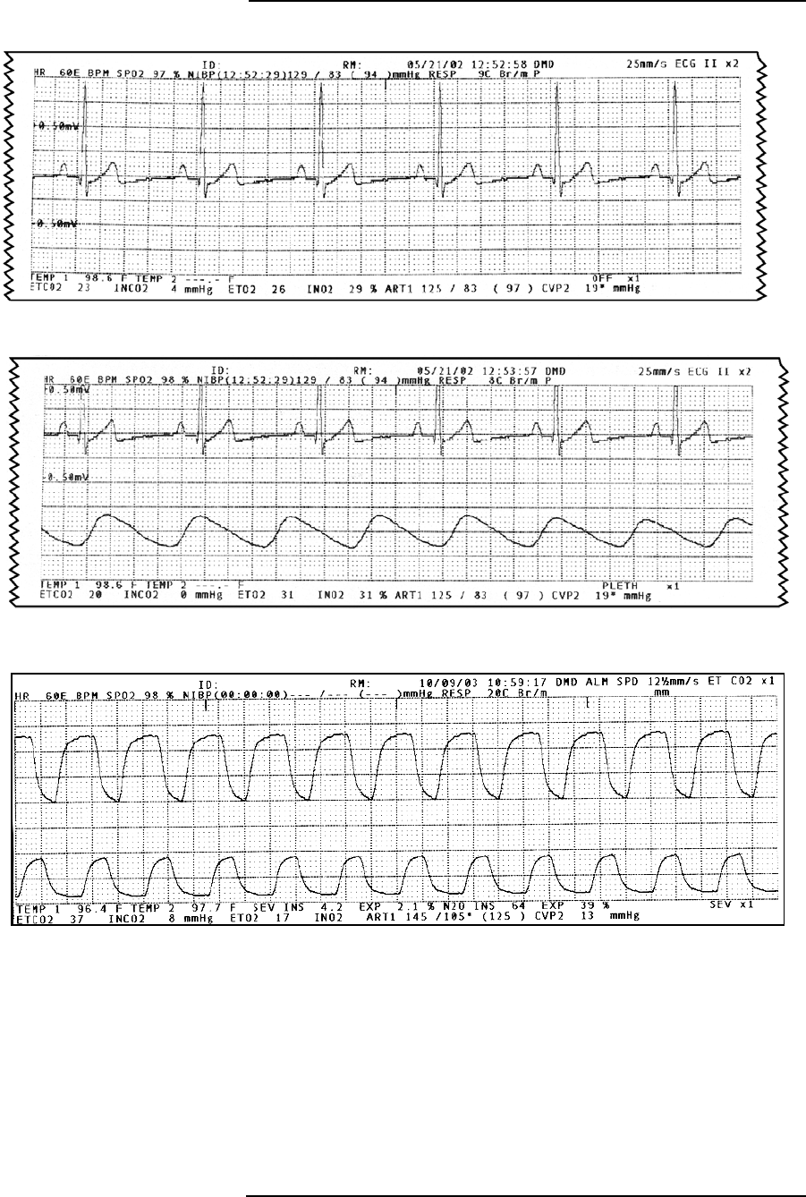
12 —5
12 —Printing and Data Ports
Figure 12-2: Single Waveform Printout
Figure 12-3: Dual Waveform Printout
Figure 12-4: Sample Agent with CO
2
Printout
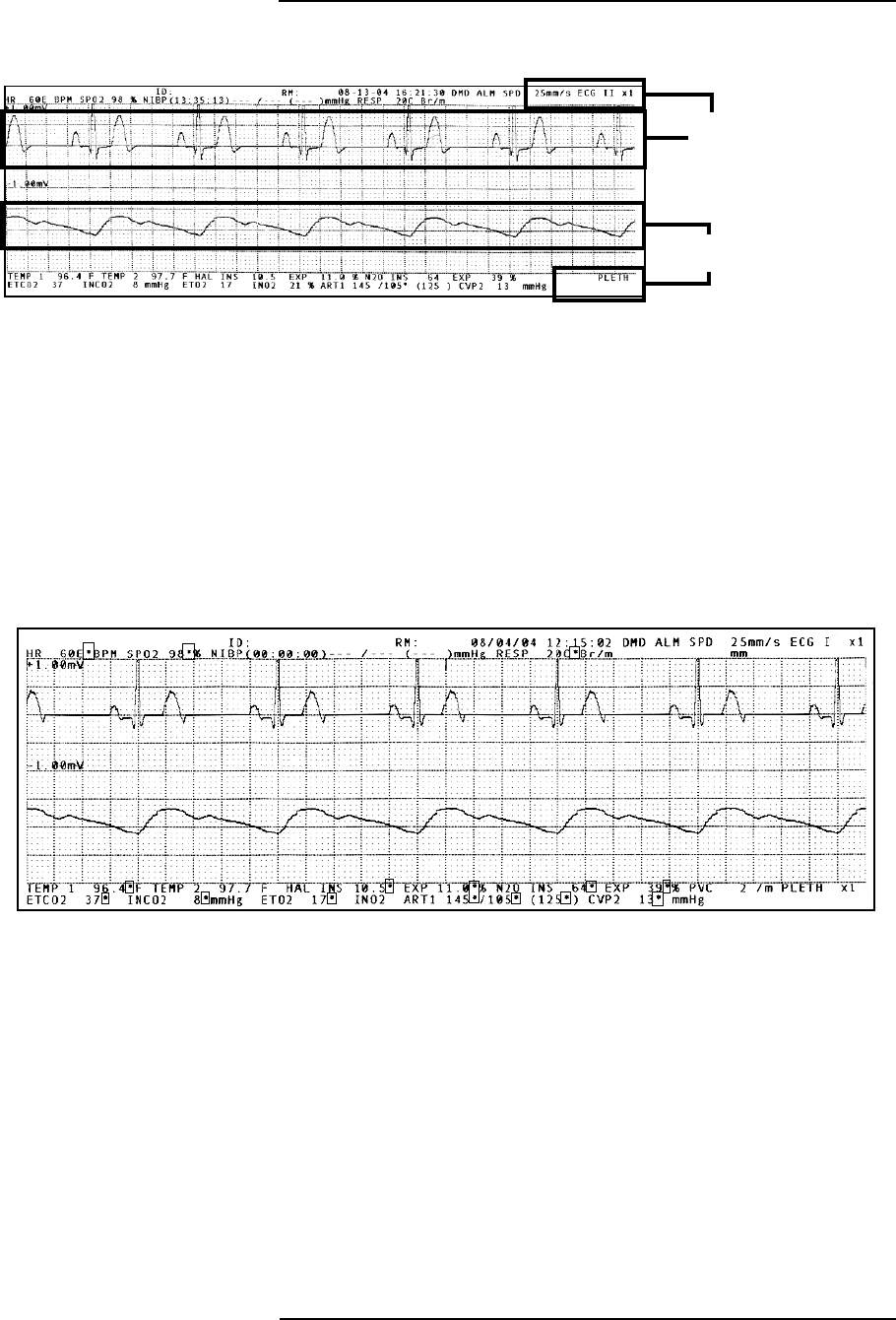
MEDRAD
Veris
8600
12 —6
Figure 12-5: Sample ECG with Pleth Printout
The printout can be configured with a variety of waveform pairs. The
example above shows an ECG waveform and a plethysmographic
waveform. The top waveform information appears in the upper right
corner of the printout. The lower waveform information appears in the
lower right corner of the printout.
The example above is the shortest printed waveform view available.
Longer printouts can be configured in the PRINT menu.
An asterisk (*) after a parameter value represents when the system
alarmed for that parameter.
Figure 12-6: Alarms Noted with Asterisks
Data in corner for
top waveform
Data in corner for
bottom waveform
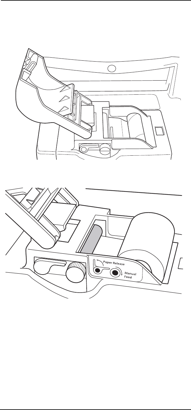
12 —7
12 —Printing and Data Ports
Changing Printer Paper
The monitor uses thermal paper. The paper must be loaded with the
thermal reactive side down as shown in the pictures below.
Open the printer door and remove the old spool.
Figure 12-7: Open The Printer Door
Insert the paper between the rollers.
Figure 12-8: Insert Paper
The paper automatically feeds when the paper is inserted.
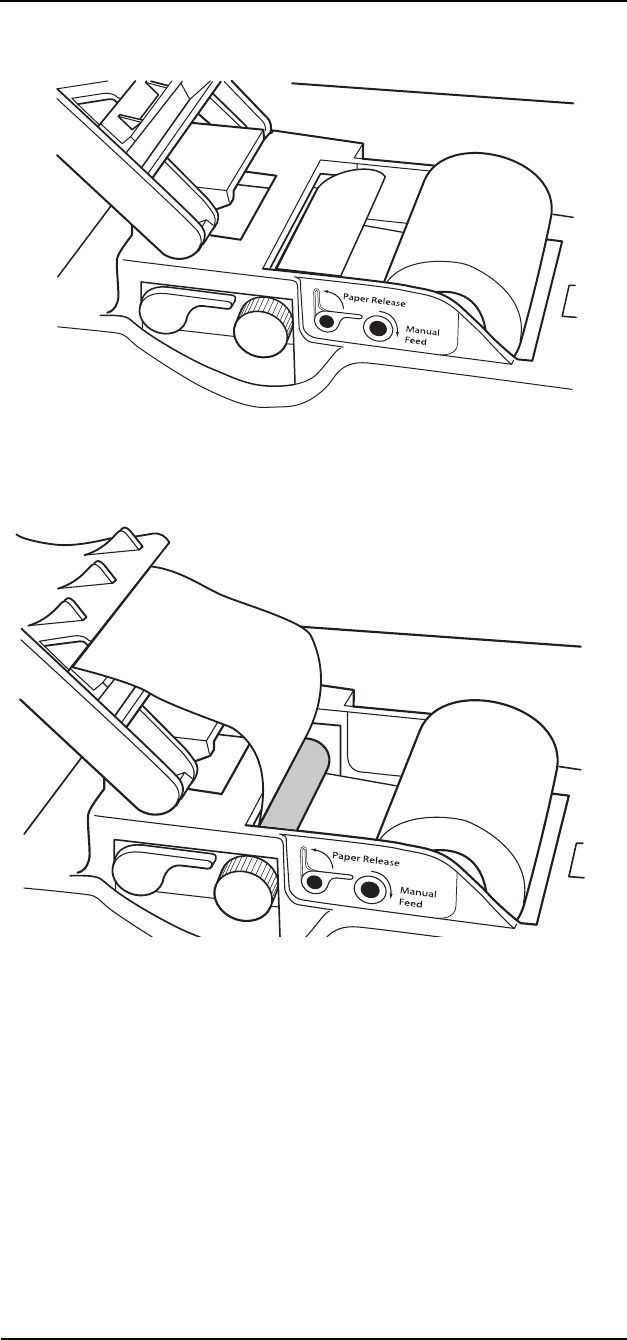
MEDRAD
Veris
8600
12 —8
Figure 12-9: Feed Paper
Close the paper door while sliding the end of the paper through the
slot in the door.
Figure 12-10: Close Door

12 —9
12 —Printing and Data Ports
Data Output Ports
The
Veris
monitor supports a variety of communication connections.
The communications ports are located along the left edge of the back
of the remote display. The ports are as follows:
• COM1 Port, RS232 Serial DB-9
• COM2 Port, MiniDIN 8, Service/Analog
NOTE: Any serial cables connected to the ports must be IEC 950 or
IEC 60950 compliant. Any peripherals connected to the monitoring
devices must be IEC 950 or IEC 60950 compliant.
COM1 Port
The monitor uses a serial port (DB-9 female) for the external data
output port and for loading system software updates. The monitor
uses a standard RS232 communication protocol with no flow control.
NOTE: This connection has a protective cover that needs to be
removed before use.
Figure 12-11: COM1 Pinout Diagram
SERIAL PRINTING
The COM 1 port supports sending data to an external serial printer or
computer terminal. To send the data as described in the beginning of
this section to the COM 1 port, the print device must be set to Serial
in the CONFIG menu. Printing is then routed to the COM1 port
instead of the internal printer.
Set the serial format to TEXT in the CONFIG menu to simulate the
tabular printout of the internal printer. Set the serial format to CSV in
the CONFIG menu to create a “comma separated variable” table. The
CSV format can be used by software programs. A description of the
CSV format is located at the end of this section.
Pinout,
DB-9 connector
Pin Signal
1 (Unused)
2 RX1
3 TX1
4 (Unused)
5 Ground
6 (Unused)
7 (Unused)
8 (Unused)
9 (Unused)
PINOUT CHART
1 2 3 4 5
6 7 8 9

MEDRAD
Veris
8600
12 —10
SENDING DATA TO A COMPUTER
Use a serial download cable to connect to standard male DB-9
computer serial ports. A common computer terminal program and an
unused RS232 serial port is needed for external communications.
MEDRAD recommends using the Windows HYPERTRM.EXE
program provided with MS Windows 95 or later operating systems.
HYPERTRM.EXE can be found in the Windows accessory directory.
For older computers using MS Windows 3.1, the communications
program TERMINAL.EXE can be found in the Windows directory.
Set the monitor to interval printing with serial output selected. With
the computer terminal connected, a data file may be collected. The
file may then be further evaluated by computer. See the description
for CSV format at the end of this section.
TERMINAL CONFIGURATION
The cable connections should be completed and the terminal
program should be configured before attempting to send data.
The recommended settings are as follows:
Baud Rate: 9600 or 19200
Parity: No Parity
Stop Bits: 1
Data Bits: 8
Hardware Control: None
EXTERNAL SERIAL PRINTER ACCESORY
The selected external printer must be configured so that it can
communicate with the monitor. Follow the configuration instructions
provided with your printer.
The required settings are as follows:
Baud Rate: 9600 or 19200
Parity: No Parity
Stop Bits: 1
Data Bits: 8

12 —11
12 —Printing and Data Ports
COM2 Port
The monitor uses the COM2 serial port (8-pin Mini DIN) for loading
system software updates and for reprogramming the monitor. The
communications ability of this port is for service use only.
There is also an analog output signal available at pin 2. For
information about sending analog data to a plotter or chart recorder
contact MEDRAD Technical Support.
The connector pinouts are shown below.
Figure 12-12: COM2 Port Pinout Diagram.
Video Port
The monitor provides a DB-15 VGA video port that is functional on
monitors with TFT screens.
4
12
5
8
7
6
3
Pinout,
DIN8 connector
Pin Signal
1 Boot 2
2 Analog Wave
3 RX 2
4 Ground
5 TXL
6 TX3
7 RX3
8 Boot 1
PINOUT CHART

MEDRAD
Veris
8600
12 —12
CSV Data Format
The Comma-Separated Variable output presents the data in a form
that is easily imported into a spreadsheet application where further
analysis can be done on the data. The data is output in ASCII format
with each field (time, heart rate, SpO
2
, IBP, CO
2
, O
2
, agent, N
2
O,
temperature, temperature type [degrees F or C], systolic, diastolic,
and map) separated with a comma. Using the Windows 3.1
TERMINAL.EXE program and EXCEL (4.0), here is an example of
how it may be used:
1. Connect the COM1 port to the serial port on the computer.
2. Start Terminal from the Accessories menu.
3. Choose Settings|Communications to set the computer's
connector to the proper port. Check communications settings.
4. Choose Transfers|Receive Text File. Assign a name to the data
(e.g. DATA.TXT) and press OK.
5. At this point, all data transmitted from the monitor will appear on
the screen and will be saved in DATA.TXT.
6. When all the desired data has been accumulated, choose
Transfers|Stop to close DATA.TXT.
7. Start EXCEL and choose File|Open.
8. Enter/Click on the file name and press the Text button.
9. For Column Delimiter, choose "Comma". For File Origin, choose
"Windows (ANSI)". Then choose OK.
10.Choose OK again from the Open dialog to open and display
DATA.TXT.
The data will be organized in a table by field. Using the EXCEL
presentation options, this data could be graphed, printed in tabular
form, or analyzed statistically in some other way.
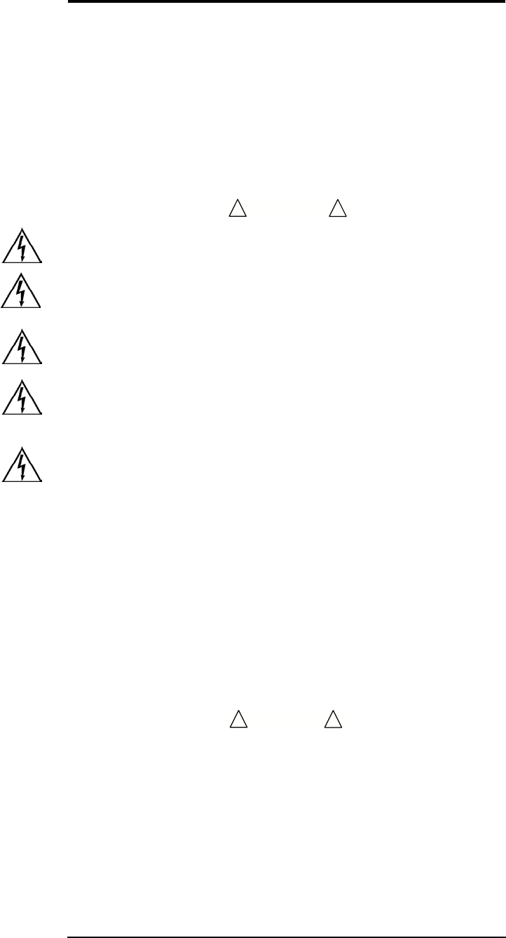
A-1
Appendix A: Maintenance
This section contains recommended procedures for maintenance,
and an operational checkout of the
Veris
8600 patient monitor.
Routine maintenance and inspection will:
• Ensure continued performance of the patient monitor.
• Reduce the possibility of equipment malfunction.
Cleaning and Disinfecting
• Shock Hazard! Turn the power off and disconnect the AC power
cable before cleaning the monitor and sensor.
• Shock Hazard! Never immerse the monitor in any liquid. The
monitor has an internal power source that is active when the
unit is unplugged.
• Shock Hazard! Do not clean the main monitor or accessories
with the patient attached to the monitor.
• Shock Hazard! Remove the power cord from the base of the
patient monitor to isolate any AC (Mains) power from the patient
monitor.
• Shock Hazard! Remove the power cord from the remote display
to isolate any AC (Mains) power from the remote display.
• Remove the main monitor from the MR Scanner room
environment to a safe location for cleaning purposes. Avoid
using cleaning products that are kept in ferromagnetic
containers.
• Avoid using ferromagnetic tools in any maintenance procedure.
• Improper disposal of batteries may result in explosion, leakage,
or personal injury. Do not open the batteries. Do not dispose of
the batteries in a fire. Follow all local and national regulations
concerning the disposal of spent Lead-acid and Lithium-Ion
batteries, or contact MEDRAD for assistance.
• Do not use abrasive cleaners on the monitor or on any sensors
or probes. Abrasive cleaners can damage the monitor, sensors,
and probes.
• The exterior surface of the monitor, except for the display
screen, may be wiped clean with alcohol and dried with a soft,
dry cloth. It is best to use a cotton cloth to clean the monitor.
Paper towels or tissues can scratch the surface of the display.
WARNING
!!
CAUTION
!!
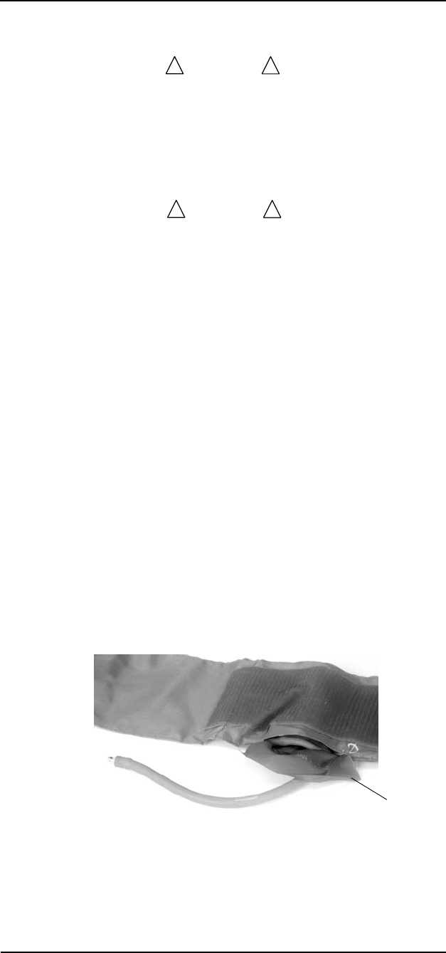
MEDRAD
Veris
8600
A-2
• Do not use full strength alcohol on the display screen. Repeated
use of strong cleaners can damage the screen. Clean the
display window by wiping it with a clean, soft, lint-free cloth
sprayed with common glass cleaner. Do not spray glass cleaner
directly on the display.
Pulse Oximeter Sensors
• Do not immerse any MEDRAD pulse oximeter sensor connector
in any liquid. Doing so may damage the connector.
The SpO2 sensor may be wiped clean with alcohol. The SpO2 sensor
may be disinfected by placing the pads and cable in a 2%
glutaraldehyde solution. Place only the sensor paddles and cable in
the solution.
Blood Pressure Cuffs
The reusable blood pressure cuff may be cleaned by wiping it with a
damp cloth or sponge. If necessary, the cuff may be disinfected by
wiping with 70% alcohol, mild bleach solution, or other disinfectant.
Disposable blood pressure cuffs are for single patient use and are not
intended to be disinfected.
The cloth cuff and neoprene bag may be sterilized with commercially
available disinfectants such as ethylene oxide (EtO). Rinse
thoroughly to remove any residual disinfectants. Do not allow liquids
to enter the neoprene bag. The cloth cuff may also be sterilized in an
autoclave.
If the cuffs become grossly soiled with blood or other body fluids, the
cloth cuffs should be laundered by hand or machine. The dacron
cloth cuff may be laundered or sterilized by first removing the
neoprene inflation bag. Feed the inflation tube back through the hole
and then pull out the cloth flap.
Figure A-1: Remove Inflation Bag from Cuff
Roll up the inflation bag and slide it out the open slot in the cloth cuff.
Be sure to observe the following laundering precautions (disposable
cuffs and neoprene inserts should not be laundered).
CAUTION
!!
CAUTION
!!
Flap

A-3
Appendix A:Maintenance
• Remove the inflatable bag from the cuff before laundering or
sterilizing the cuff.
• Strong bleach solutions will damage the cuff.
• Temperatures over 275° F (135° C) will damage the cuff.
• Close the Velcro® fastener before laundering the cuff.
• Soaking the cuff in dark-colored solutions may stain or discolor
the cuff.
Hand laundering (as opposed to machine laundering) prolongs the
life of the cuff. Wash the cuff in warm, soapy water. Rinse the cuff
thoroughly. After cleaning the cuff, allow the cuff to air dry, then insert
the inflation bag in the cuff.
Temperature
The temperature cable and probe may be wiped clean with alcohol.
The temperature cable and probe may be disinfected by wiping the
cable and probe in a 2% glutaraldehyde solution. Do not place either
the cable nor the probe in the solution.
TEMPERATURE PROBE
Clean the probe according to the hospital protocol for cleaning of
reusable equipment cables and probes. Typically this protocol
consists of the following:
1. Disconnect the cable from the monitor and temperature sensor
(probe).
2. Wipe the probe with a nonabrasive cloth moistened with a mild
detergent and warm water or disinfectant. Dry thoroughly.
3. Do not use solvents to clean the probe.
4. Do not allow the probe connectors and contact points to come in
contact with liquids.
5. Do not fully immerse the probe in liquids.
6. Do not autoclave or EtO sterilize the probe.

MEDRAD
Veris
8600
A-4
Accidental Wetting
• Shock Hazard! The monitor is an AC powered device and an
immersed monitor presents a danger to anyone who handles
the device.
The action to be taken following accidental wetting of the equipment
is as follows:
1. Turn the power off! Disconnect the AC power cord from the
monitor, remote display, or power supply.
2. If monitoring a patient, transfer the patient to another monitor as
quickly as possible.
3. Use a clean, dry towel or cloth to remove the liquid from the
housing.
4. The monitor, remote display, or power supply should be
inspected by a service technician as soon as possible.
5. If the internal mechanism is saturated, allow the liquid to drain
out for 24 hours before shipping.
6. If liquid has entered the monitor, remote display, or power
supply, it needs to be dried and cleaned internally. Full testing is
required before the monitor, remote display, or power supply
can be used. Contact the MEDRAD Service Department as
soon as possible.
Time is critical! The longer any liquid remains in the monitor, remote
display, or power supply, the more damage it can do. It is important to
service the monitor, remote display, or power supply immediately
after any liquid is spilled into it.
WARNING
!!

A-5
Appendix A:Maintenance
Annual Safety Tests
The monitor and remote display should be electrically tested
annually. The safety tests should be performed only by experienced
service technicians. Refer to the
Veris
8600 Service Manual for
additional information.
System Testing
The monitor has built-in system tests which should be performed
regularly. However, the tests should be performed by qualified service
personnel only.
Service Checks
If the monitor shows any signs of physical damage, contact MEDRAD
Service immediately.
Have a qualified service technician perform the following
performance and safety checks annually.
• Perform complete functional testing of the monitor.
• Test the monitor for electrical leakage and withstanding voltage.
Do not remove the cover. Refer all servicing to a qualified technician.
Descriptions of these tests can be found in the
Veris
8600 Service
Manual. Some tests may require specialized equipment.

MEDRAD
Veris
8600
A-6
Maintenance Schedule
Your
Veris
8600 patient monitor must be properly maintained to
ensure that it is in peak operating condition. Your individual
maintenance system and schedule depends upon how your monitor
is used, the type of procedures performed, and frequency of use. The
following maintenance schedule is recommended for the system:
MEDRAD also recommends that a complete system calibration and
performance checkout be performed annually. Contact MEDRAD
Factory Service, or your local MEDRAD office for complete details.
In the United States, Canada, and Europe, the MEDRAD Service
Department offers Preventive Maintenance Programs. These annual
programs greatly assist in maintaining accuracy and reliability, and
can also extend the life of the system. Contact MEDRAD for details,
In Europe, contact your local MEDRAD office or your local authorized
dealer for further information. Refer to “In Case of Emergency
Contact” on page xi.
NOTES: If not using the monitor on a patient, keep it plugged into the
power supply for continuous charging.
Failures which occur due to lack of proper maintenance will not be
covered under warranty.
Local regulations or hospital protocol may require electrical leakage
checks at more frequent intervals. If this applies, local regulations for
leakage must be followed.
Every Patient • Clean and disinfect the sensor cables and sensor.
• Inspect the accessories and cables for damage.
• Change the gas sampling device and sampling line.
• Check the NIBP function.
• Change the water trap
Every Day • Charge the batteries as necessary. If not using the monitor on a
patient, keep it plugged into the power supply for continuous
charging.
• Test the NIBP function.
Every Week • Charge the ECG module battery.
• Compare temperature function with another temperature source.
Every 3 Months • Clean the exterior of the unit (or clean as needed).
• Fully charge the batteries.
• Check the O2 cell. Change if necessary.
Every Year • Perform the annual safety tests described above.
• Perform NIBP calibration and safety test
•Verify the CO
2 and agent gas auto-calibration. Calibrate if
necessary.
• Change the O2 cell.
• Check the CO2 absorber. Change if necessary
• Check the gas flow rate. Adjust if necessary.

MEDRAD
Veris
8600
A-7
Long-Term Storage
No special preparation is necessary for long term storage of the
monitor.
Disposal
At the end of its useful life, the monitor and its accessories may be
disposed of according to your institution's policies and procedures
and any local and national policies and procedures for disposal of
patient-contact medical waste. Discard disposable medical waste
according to your institution's policies and procedures to prevent
biological contamination.
Alternately, the monitor and its accessories may be returned to
MEDRAD, Inc., for safe disposal. The shipping address is:
MEDRAD, Inc.
One Medrad Drive
Indianola, PA 15051-0780

B-1
Appendix B: Unit and
Configuration
Defaults
Restoring the Unit Default
Profile
A set of unit defaults are pre loaded into the non-volatile memory of
the monitor. These defaults can be used as they exist, or can be used
as the basis for creating your own default profile.
The unit default profile can be modified or renamed or replaced if
desired. If you modify the unit defaults it is recommended that you
rename them.
1. Press the DEFAULT button. The Restore Unit Defaults menu
appears. The SELECT option and the currently active profile are
both highlighted.
2. Press the menu knob to scroll through the choices.
3. Turn the knob to ACCEPT.
4. Press the menu knob once. The message Action Completed is
highlighted.
5. Press the menu knob to re-establish the profile. The monitor
returns to the main menu.
Default Settings
Unit Default Settings
Customized defaults can be saved for use at a later time. Starting
from the monitor’s main screen, do the following:
1. Set specific defaults for parameters and alarms. These are set
through the ALARMS, PARAMS, DISPLAY, CONFIG, and
PRINT softkeys.
2. Press and hold the DEFAULT button located on the front panel.
The Set Unit Defaults dialog box appears.
NOTE: If the Set Unit Defaults dialog box that prompts you to
enter a password did not appear, you did not hold the button in
properly. In this case, turn the knob to highlight and select
CANCEL, or you could lose the settings just created.

MEDRAD
Veris
8600
B-2
3. Enter the password MEDRAD (required to save the customized
default):
• Turn the menu knob to highlight a single letter or number.
• Press the menu knob to select that letter or number.
• Continue for each letter and number of the password.
• After pressing the menu knob for the last figure of the
password, the monitor indicates acceptance of the password
by displaying the Set Unit Defaults window.
4. When the Set Unit Defaults window displays, both SELECT and
CUSTOM DEFAULTS are highlighted.
Figure B-1: Set Unit Defaults Screen
NOTE: Selecting a value in Set Unit Defaults window is different than
other windows. At this point in this procedure, the right column of this
window is active.
5. With both SELECT and CUSTOM DEFAULTS highlighted in the
Set Unit Defaults window, press the menu knob to scroll the
highlight bar down the right-hand column list to the desired
default to be changed. Press to select.
6. Turn the menu knob to scroll the highlight bar to EDIT. Press to
select. The selected default remains highlighted as the menu
knob is rotated. The first letter of the selected default is
highlighted when the menu knob is pressed.
7. Change the label to the new default name by turning the menu
knob to select the first letter in the new name for the default.
Press to select. The next letter is automatically highlighted.
Continue for the remaining letters of the new default name.
8. After completing the last letter of the new name, press the menu
knob until the entire label name is highlighted. This indicates
that entry is complete, but not accepted.
Set Unit Defaults
Replace all configuration
and alarm settings with
unit default settings.
SELECT
EDIT
ACCEPT
CUSTOM DEFAULTS
STD DEFAULTS
STD DEFAULTS
STD DEFAULTS
STD DEFAULTS
CANCEL

B-3
Appendix B:Unit and Configuration Defaults
9. To accept the new label name, turn the menu knob to highlight
ACCEPT and press to select. The message Action Completed
appears.
Figure B-2: Set Units Defaults After Modifications
10.Press the menu knob. Your new default set of is saved in
memory.
11.Press the ON/OFF button, located on the front panel, to turn off
the monitor.
Configuration Default Settings
1. From the Set Unit Defaults screen, press and hold the DEFAULT
key again. The Install Configuration Defaults screen displays.
(See Figure B-3: ”Install Configuration Defaults Screen”).
Figure B-3: Install Configuration Defaults Screen
The Install Configuration Defaults screen permits choosing which set
of 3 defaults are available to the user.
Set Unit Defaults
Set current configuration
and alarm settings as new
unit default settings.
CANCEL
SELECT
EDIT
ACCEPT
CUSTOM DEFAULTS
NEW DEFAULT
STD DEFAULTS
STD DEFAULTS
STD DEFAULTS
Install Configuration Defaults
Replace the current set of
configuration defaults with
a different set of defaults.
SELECT
ACCEPT
Base System
Cardiac System
Anesthesia System
CANCEL

MEDRAD
Veris
8600
B-4
The selection procedure works the same as in the previous screens.
1. WIth the SELECT feature highlighted, press the menu knob to
select from Base System, Cardiac System or Anesthesia
System (depending upon your unit’s configuration).
2. Turn the menu knob to select ACCEPT. The message Action
Completed appears. Press the menu knob to effect the change.
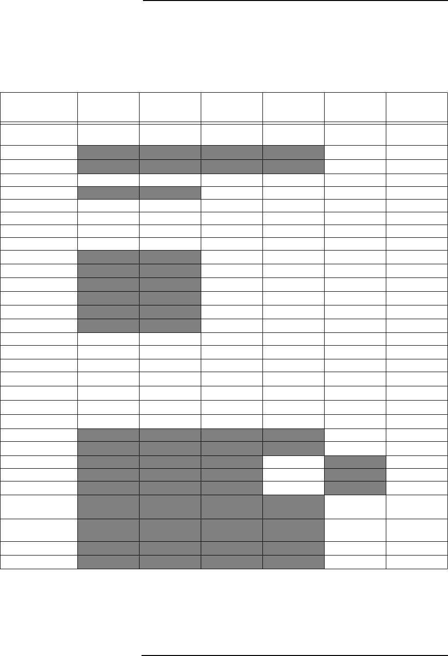
B-5
Appendix B:Unit and Configuration Defaults
Configuration Settings for Unit
Defaults
The configuration settings for the three configuration setup defaults
are the same as the basic hospital configuration settings except for
the following, grouped by menu:
PARAMS Menu Settings
Setting Base BasePlus Cardiac Cardiac
with Temp Anesthesia Anesthesia
with Temp
Audible Tone
Volume
555555
CO
2
ON ON
O
2
ON ON
HR Source Smart Smart Smart Smart Smart Smart
Gating OFF OFF OFF OFF
ECG ONONONONONON
ECG Cable 3 lead 3 lead 5 lead 5 lead 5 lead 5 lead
ECG Filter Monitor Monitor Monitor Monitor Monitor Monitor
Auto Lead Switching NO NO YES YES YES YES
IBP1 Site ART ART ART ART
IBP 1 Range 0 to 200 0 to 200 0 to 200 0 to 200
IBP 1 Zero None None None None
IBP2 Site CVP CVP CVP CVP
IBP 2 Range 0 to 20 0 to 20 0 to 20 0 to 20
IBP 2 Zero None None None None
NIBP ON ON ON ON ON ON
NIBP Tone None None None None None None
NIBP Cycle Time OFF OFF OFF OFF OFF OFF
SpO
2
ON ON ON ON ON ON
SpO
2
Average 12 12 12 12 12 12
SpO
2
Search Time 20 20 20 20 20 20
SpO
2
Low Limit Alarm High High High High High High
Respiration ON ON
Respiration source CO
2
CO
2
Temp1 ON ON
Temp2 ON ON
Unit of Measure °F °F
CO
2
Unit of
Measure mmHg mmHg
Agent to Monitor
(Primary) Automatic Automatic
Gas Flow Rate 200 ml 200 ml
Flow Mode Exhaust Exhaust

MEDRAD
Veris
8600
B-6
PRINT Menu Settings
* Available as an option if the system has a remote display
DISPLAY Menu Settings
Setting Base BasePlus
Cardiac;
Cardiac
w/Temp—
w/o Remote
Display
Cardiac;
Cardiac
w/Temp—
w/Remote
Display
Anesthesia;
Anesthesia
w/Temp—
w/o Remote
Display
Anesthesia;
Anesthesia
w/Temp—
w/o Remote
Display
Print Type
(Demand) na Graphical na Graphical na Graphical
Alarm Print na OFF na OFF na OFF
BP Print na Off na Off na Off
Interval Print na Off na Off na Off
Interval Print Type na Tabular na Tabular na Tabular
Snapshot Size na 6 seconds na 6 seconds na 6 seconds
History Size na 6 seconds na 6 seconds na 6 seconds
Waveform 1 na ECG II na ECG II na ECG II
Gain (waveform 1) na x1.0 na x1.0 na x1.0
Waveform 2 na PLETH na PLETH na PLETH
Gain (waveform 2) na x1.0 na x1.0 na x1.0
Printer Speed na 25.0 mm/sec na 25.0 mm/sec na 25.0 mm/sec
Setting Base/BasePlus All Cardiac and
Anesthesia Units
Waveform 1 ECG II,x1,25,25 ECG II,x1,25,25
Waveform 2 OFF OFF
Waveform 3 ECG I,x1,25,25 ECG I,x1,25,25
Waveform 4 PLETH,x1,25,25 PLETH,x1,25,25
Waveform 5 OFF aVL
Waveform 6 OFF aVR

B-7
Appendix B:Unit and Configuration Defaults
ALARMS Menu Settings
Setting Base BasePlus Cardiac Cardiac
with Temp Anesthesia Anesthesia
with Temp
Heart Rate (High)
Adult, Pediatric 150 150 150 150 150 150
Neonate 180 180 180 180 180 180
Heart Rate (Low)
Adult, Pediatric 40 40 40 40 40 40
Neonate 90 90 90 90 90 90
SpO
2
(High) OFF OFF OFF OFF OFF OFF
SpO
2
(Low) 909090909090
NIBP Systolic (High)
Adult, Pediatric 200 200 200 200 200 200
Neonate 140 140 140 140 140 140
NIBP Systolic (Low)
Adult, Pediatric505050505050
Neonate 35 35 35 35 35 35
NIBP Diastolic (High)
Adult, Pediatric 100 100 100 100 100 100
Neonate 80 80 80 80 80 80
NIBP Diastolic (Low)
Adult, Pediatric303030303030
Neonate 30 30 30 30 30 30
NIBP Mean (High)
Adult, Pediatric 150 150 150 150 150 150
Neonate 100 100 100 100 100 100
NIBP Mean (Low)
Adult, Pediatric505050505050
Neonate 35 35 35 35 35 35
Temperature 1/2
(High) na na na 100 na 100
Temperature1/ 2 (Low) na na na 93 na 93
Respiration (High)
Adult, Pediatricnananana3636
Neonate na na na na 60 60
Respiration (Low)
Adult, Pediatricnananana 4 4
Neonate na na na na 14 14
CO
2
Inspired (High) na na na na 10 10
CO
2
Inspired (Low)nananana 5 5
CO
2
Expired (High) na na na na 55 55
CO
2
Expired (Low)nananana2020

MEDRAD
Veris
8600
B-8
O
2
Inspired (High) na na na na 100 100
O
2
Inspired (Low)nananana1818
O
2
Expired (High) na na na na 100 100
O
2
Expired (Low) na na na na OFF OFF
IBP1 Systolic (High)
Adult, Pediatric na na 200 200 200 200
Neonate na na 140 140 140 140
IBP1 Systolic (Low)
Adult, Pediatricnana50505050
Neonate na na 50 50 50 50
IBP1 Diastolic (High)
Adult, Pediatric na na 100 100 100 100
Neonate na na 80 80 80 80
IBP1 Diastolic (Low)
Adult, Pediatricnana30303030
Neonate na na 30 30 30 30
IBP1 Mean (High)
Adult, Pediatric na na 150 150 150 150
Neonate na na 100 100 100 100
IBP1 Mean (Low)
Adult, Pediatricnana50505050
Neonate na na 40 40 40 40
IBP2 Mean (High) na na 15 15 15 15
IBP2 Mean (Low) nana1111
ART Systolic (High)
Adult, Pediatric na na 200 200 200 200
Neonate na na 140 140 140 140
ART Systolic (Low)
Adult, Pediatricnana50505050
Neonate na na 50 50 50 50
ART Diastolic (High)
Adult, Pediatric na na 100 100 100 100
Neonate na na 80 80 80 80
ART Diastolic (Low)
Adult, Pediatricnana30303030
Neonate na na 30 30 30 30
ART Mean (High)
Adult, Pediatric na na 150 150 150 150
Neonate na na 100 100 100 100
Setting Base BasePlus Cardiac Cardiac
with Temp Anesthesia Anesthesia
with Temp

B-9
Appendix B:Unit and Configuration Defaults
ART Mean (Low)
Adult, Pediatricnana50505050
Neonate na na 40 40 40 40
PA Systolic (High) na na 40 40 40 40
PA Systolic (Low) na na 15 15 15 15
PA Diastolic (High) na na 15 15 15 15
PA Diastolic (Low) nana5555
PA Mean (High) na na 20 20 20 20
PA Mean (Low) na na 10 10 10 10
LA Mean (High) na na 15 15 15 15
LA Mean (Low) nana1111
LV Systolic (High)
Adult na na 200 200 200 200
Pediatric, Neonatenana0000
LV Systolic (Low)
Adultnana60606060
Pediatric, Neonatenana0000
LV Diastolic (High)
Adultnana40404040
Pediatric, Neonatenana0000
LV Diastolic (Low)
Adultnana0000
Pediatric, Neonatenana0000
LV Mean (High)
Adult na na 120 120 120 120
Pediatric, Neonatenana0000
LV Mean (Low)
Adultnana60606060
Pediatric, Neonatenana0000
RA Mean (High) na na 15 15 15 15
RA Mean (Low) nana1111
RV Systolic (High)
Adultnana50505050
Pediatric, Neonatenana0000
RV Systolic (Low)
Adultnana20202020
Pediatric, Neonatenana0000
RV Diastolic (High)
Adultnana20202020
Pediatric, Neonatenana0000
Setting Base BasePlus Cardiac Cardiac
with Temp Anesthesia Anesthesia
with Temp

MEDRAD
Veris
8600
B-10
RV Diastolic (Low)
Adultnana0000
Pediatric, Neonatenana0000
RV Mean (High)
Adultnana30303030
Pediatric, Neonatenana0000
RV Mean (Low)
Adultnana10101010
Pediatric, Neonatenana0000
CVP Mean (High) na na 15 15 15 15
CVP Mean (Low) nana1111
ICP Mean (High) na na 15 15 15 15
ICP Mean (Low) nana1111
Primary Inspired
(High) na na na na 2.3 2.3
Primary Inspired (Low) na na na na OFF OFF
Primary Expired (High) na na na na 1.5 1.5
Primary Expired (Low) na na na na OFF OFF
N
2
O Inspired (High) na na na na 75 75
N
2
O Inspired (Low)nanananaOFFOFF
N
2
O Expired (High) na na na na OFF OFF
N
2
O Expired (Low) na na na na OFF OFF
HAL Inspired (High) na na na na 2.3 2.3
HAL Inspired (Low)nanananaOFFOFF
HAL Expired (High) na na na na 1.5 1.5
HAL Expired (Low) na na na na OFF OFF
ENF Inspired (High) na na na na 4.8 4.8
ENF Inspired (Low)nanananaOFFOFF
ENF Expired (High) na na na na 3.2 3.2
ENF Expired (Low) na na na na OFF OFF
ISO Inspired (High) na na na na 3.6 3.6
ISO Inspired (Low) na na na na OFF OFF
ISO Expired (High) na na na na 2.4 2.4
ISO Expired (Low)nanananaOFFOFF
DES Inspired (High) na na na na 18.0 18.0
DES Inspired (Low) na na na na OFF OFF
DES Expired (High) na na na na 12.0 12.0
DES Expired (Low) na na na na OFF OFF
SEV Inspired (High) na na na na 5.1 5.1
SEV Inspired (Low) na na na na OFF OFF
Setting Base BasePlus Cardiac Cardiac
with Temp Anesthesia Anesthesia
with Temp

B-11
Appendix B:Unit and Configuration Defaults
Other Alarm Settings
SEV Expired (High) na na na na 3.4 3.4
SEV Expired (Low) na na na na OFF OFF
Setting Base BasePlus Cardiac Cardiac
with Temp Anesthesia Anesthesia
with Temp
All models Value
Alarm Volume 5
Apnea 20 seconds
ECG Lead Fail Medium

C-1
Appendix C: Specifications
ECG
ECG System
Lead Selection: 3-Lead; I, II, III
5-Lead; I, II, III, aVR, aVL, aVF, V
Frequency Response: Monitor; 1-40Hz (-3dB)
Safety Standards: UL60601-1
CAN/CSA C22.2 No. 601.1-M90
IEC 60601-1, IEC 60601-2-27
EMC Standards: IEC 60601-1-2 2nd Edition, CISPR11 Class B
ECG Module
Dimensions: 13.34cm. x 9.14 cm. x 3.10cm.
(5.25 in. x 3.60 in. x 1.22 in.)
Lead Connectors: 3 or 5 Lead, Standard AAMI (DIN 42-802)
Lead Connector Color Code: American Heart Association (AHA)
Patient Isolation: Type CF
Defibrillation Protection: Yes
Electrosurgery Protection: No
HF Equipment Protection: No
Pacemaker Pulse Rejection: No
Battery: Rechargeable 7.4V, 1.5Ah Lithium-Polymer,
internal, not user-serviceable, see “Disposal”
on page A-7 for disposal instructions
Battery Life: Approximately 40 hours of continuous use
Low Battery Indication: Indication provided at approximately 7 hours
of continuous use remaining
Protection Against Water Ingress: IPX1
MR Environment Safety: MR Safe
Leadset
Description: MR-Compatible, Radio Translucent, 14in
(35.6 cm)
Configurations: 3-Lead: RA (White); LA (Black); LL (Red)
5-Lead: RA (White); LA (Black); LL (Red);
V (Brown); RL (Green)
Lead Color Code: AHA
MR Environment Safety: MR Safe

MEDRAD
Veris
8600
C-2
ECG Module Charger
Dimensions: 12.0cm. x 5.3cm. x 3.8cm.
(4.73 in. x 2.1 in. x 1.5 in.)
AC Input: 100-250VAC, 50/60Hz
AC Input Connection: Universal IEC inlet; use supplied cord
Output: 600mA at 7.4VDC
Charge Time: Less than 3 hours
Classification: Class II Medical Power Supply
MR Environment Safety: NOT safe for use in Magnet Room
Charge Status Indicator (Green LED): No Battery; Off
Charge Pending; Blip (10% ON)
Rapid Charge; Flash (50%)
Charge Complete; On
Charge Failure; Blip
SpO
2
Range: 1-99%.
Resolution: 1 percent of full scale
Accuracy: ± 2 percent of full scale at 70 – 99%;
± 3 percent of full scale at 50 – 69%.
< 50% oxygen saturation is unspecified.
Averaging Time: User selectable:
3, 6, 9, 12, 15, 18, and 21 seconds.
Search Time: User selectable: 10, 20, 30, and 40 seconds.
Indications Plethysmographic waveform, Numeric
display.
Method: Dual wavelength LED, Fiber Optic
Modes: Adult/Pediatric/Neonate
Operation: Continuous Use
Sensor Wavelength: 660nm/905nm
Sensor Power: <80mW
Heart Rate
Source: Smart Switching;
ECG (primary), IBP, Pleth, NIBP
Range: 20-300 bpm (ECG, IBP, Pleth)
30-240 bpm (NIBP)
Accuracy: ± 1bpm or 1% (ECG, IBP, Pleth)
± 1 bpm or ±1% (NIBP)
Pulse Tone: Selectable, On/Off

C-3
Appendix C:Specifications
Gating
Signal Source: ECG, SpO
2
Pulse output: 50msec (±10%) pulse width, synchronous
with the r-wave or corresponding peak of the
plethysmogram waveform.
Waveform output: One of the following, 1.5mV (±0.5mv) ECG or
plethysmogram waveform.
Gating Signal Delay: <10 milliseconds (ECG), <20 milliseconds
(SpO
2
)
Visual Indication: Icon at the upper right corner of the display
(ECG parameter box).
Function: User selectable: Off, ECG Waveform or
Pulse, SpO
2
Waveform or Pulse.
The gating function provides gating signals
97% of the time or greater after the first 2
pulses of a scanner RF sequence.
Temperature
Channels: 2
Technique: Fluoroptic Thermometer
Range: 68°F to 113°F (20°C to 45°C)
Accuracy: 68° – 94.8°F, ±0.5%
95° – 107.5°F, ±0.2%
107.6° – 113°F, ±0.5%
Sensor Type: Reusable, Fiber Optic Surface Probe.
NIBP
Technique: Oscillometric measure upon inflation
Measurement Time: <40 seconds average; standard adult cuff
Automatic Measurement Cycles: 2, 3, 5, 10, 15, 30, 60 min; 2, 4 hrs
Measurable Pressure Range: Adult; 30 to 300 mmHg
Pediatric; 30 to 300 mmHg
Neonatal; 20 to 150 mmHg
Resolution: 1 mmHg
Transducer Accuracy: The greater of ± 2 mmHg or 2% of reading
STAT mode: 5 min of consecutive readings

MEDRAD
Veris
8600
C-4
Invasive Blood Pressure
Channels: 2
Transducer Sites: Selectable:
ART, PA, LA, RA, CVP, ICP, RV, LV
Pressure Range: -10mmHg to 300mmHg (increments of
1mmHg)
Zero Offset: ±150 mmHg
Transducer Sensitivity: 5µV/V/mmHg
Resolution: 1 mmHg
Excitation Voltage: 5 volts ± 0.1 volt
Accuracy: ±1 mmHg or ±1%, whichever is greater
Scale Range: -10 to 10, 0 to 20, 0 to 30, 0 to 40, 0 to 60,
0 to 100, 0 to 150, 0 to 200, 0 to 300,
and Automatic
Defibrillation Protection: Yes
Transducer
Frequency Response: 20 Hz
Transducer Impedance: > 300 ohms
Transducer Sensitivity: 5 micro volts per volt per mmHg
Pressure Range: -20 mmHg to 300 mmHg
Capnometry (CO
2
)
Method: Sidestream; non-dispersive infrared (NDIR)
Range: 0-99 mmHg, 0-12.5%, 0-12.5 kPa, 0-99 Torr
Resolution: 1 mmHg, 0.1%, 0.1 kPa, 1 Torr
Accuracy: ±0.2% abs. or 4% of reading for breath rates
up to 60 bpm
Maximum Rise Time: With a concentration of 10% CO
2
, 10-90% of
maximum:
350 milliseconds at 100 ml/min
300 milliseconds at 150 ml/min
250 milliseconds at 200 ml/min
Response Time: 7.0 seconds (100 ml/min)
5.0 seconds (150 ml/min)
4.0 seconds (200 ml/min)
Calibration: Auto-calibrating
Units: mmHg; Volume Percent; kPa; Torr
Display: Inspired CO
2
, Expired CO
2
(End-Tidal)
Numerical values, capnograph, and breath by
breath ETCO
2
bar graph.
CO
2
Respiration
Source: Capnogram
Range: 1 to 100 breaths/minute
Resolution: 1 breath/minute
Accuracy: The greater of ± 2 breaths/minute or ±2% of
reading

C-5
Appendix C:Specifications
Halogenated Agents
Method: Sidestream; non-dispersive infrared
Units: Volume Percent
Resolution: 0.1 Volume Percent
Range: Halothane; 0 to 10.0 vol. %
Isoflurane; 0 to 10.0 vol. %
Enflurane; 0 to 10.0 vol. %
Desflurane; 0 to 20.0 vol. %
Sevoflurane; 0 to 10.0 vol. %
Accuracy: ± (0.1% abs. + 4% of reading) for breath
rates up to 60 bpm.
Identification Threshold: Halothane; 0.2 vol. %
Isoflurane; 0.3 vol. %
Enflurane; 0.3 vol. %
Desflurane; 0.3 vol. %
Sevoflurane; 0.3 vol. %
Mixed Gas Threshold: 0.2 vol. % + 10% of total concentration for
breath rates up to 60 bpm.
Primary Agent Identification: User Selectable or Automatic
Mixed Agent Identification: Automatic (secondary agent)
Maximum Rise Time: With a concentration of 10% of the
halogenated agent, 10-90% of maximum:
650 msec. for (10-90%) at 100 ml/min
500 msec. for (10-90%) at 150 ml/min
400 msec. for (10-90%) at 200 ml/min
Maximum System Response Time: 7.5 seconds (100 ml/min)
5.5 seconds (150 ml/min)
4.5 seconds (200 ml/min)
Warm-up Time: 1 minute to first waveforms
< 20 minutes to full accuracy
Calibration: Auto-calibrating
Auto Zeroing: Occurs 30 to 60 minutes
Duration 3.0 to 7.0 seconds
Display: Primary agent inspired and expired numerical
values, Primary agent waveform, Secondary
(mixed) agent numerical values
Effect of Interfering Gases: Ethyl alcohol: Negligible
Metabolic ketones, Acetone: Negligible
Carbon dioxide: Negligible
Nitrous oxide: Negligible
Helium: Negligible
Ether: Contraindicated
Cyclopropane: Contraindicated
Methoxyflurane: Contraindicated

MEDRAD
Veris
8600
C-6
Nitrous Oxide (N
2
O)
Method: Sidestream; non-dispersive infrared (NDIR)
Range: 0 to 99 volume percent
Resolution: 1%
Accuracy: ± (1.5% abs. + 4% of reading) for breath
rates up to 60 bpm.
Identification Threshold: 5% (for single and mixed agents)
Maximum Rise Time: With a concentration of 100% N2O, 10-90%
of maximum:
(10-90%) 400 milliseconds at 100 ml/min
(10-90%) 300 milliseconds at 150 ml/min
(10-90%) 250 milliseconds at 200 ml/min
Maximum System Response Time: 7.0 seconds (100 ml/min)
5.0 seconds (150 ml/min)
4.0 seconds (200 ml/min)
Calibration: Auto-calibrating
Units: Percent
Display: Numerical Inspired N
2
O, Expired N
2
O; N
2
O
waveform
Oxygen Monitoring (O
2
)
Units: Percent
Display: Inspired O
2
, expired O
2
Numerical values, waveform
Method: Oxidation-reduction galvanic cell
Range: 0-100%
Resolution: 1%
Accuracy: ± 3 vol. % (0 - 90%)
± 4 vol. % (91- 100%)
Maximum Rise Time: With a concentration of 80% O
2
, 0-90% of
maximum
700 milliseconds at 100 ml/min
550 milliseconds at 150 ml/min
500 milliseconds at 200 ml/min
Maximum System Response Time: 8.0 seconds (100 ml/min)
5.5 seconds (150 ml/min)
4.5 seconds (200 ml/min)
Pneumatics
Flow rate: 100, 150, 200 ml/min, User Selectable
Occlusion Clearing: Automatic
Filters: WaterChek™ 2+
Sample Lines: 16 foot
Pneumatic Sound Pressure: 45 dBa maximum @ 1 meter

C-7
Appendix C:Specifications
Alarms
Characteristics: EN 475, Adjustable
Indication: Audible; Visual
Levels: High, Medium, Low, Informational,
Medium Quiet, Informational Quiet
Settings: User Defaults, Hospital Defaults,
Factory Defaults
Alarm Modes: Adult/Pediatric/Neonate,
High and low limit settings for each mode.
Volume: User Adjustable (1-10)
Silence: Yes; 2 minutes or permanent
Trend Reports
Types: Tabular and Graphical
Trend memory: 24 hours (with NIBP every 3 minutes)
Tabular Intervals: 30 sec., 1, 2, 5,10, 30 min., 1, 2, 4 hrs.
Graphical Span: 2, 4, 8, 12, or 24 hours
Data Types: HR, SpO
2
, Temp., Resp., EtCO
2
,
INCO
2
, Expired O
2
, Inspired O
2
,
NIBP (Systolic, Diastolic, Mean)
IBP (Systolic, Diastolic, Mean)
Agents, N
2
O
Printer (Remote Display only)
Recorder Type: Internal thermal line printer
Data Formats: Single or dual waveform; Tabular
Paper Speed: 12.5 or 25mm/sec continuous.
(Snapshot at 50mm/sec)
Controls
Screen: 10.4" active color TFT
Resolution: 640 x 480 pixels
Waveforms: 6, maximum
Waveform Display Gain: .5×, 1×, 2×, 4× user selectable
Waveform Sweep Speed: 6.25, 12.5, 25 or 50 mm/sec, selectable
Display Update Period: 1.0 second
Keys: 9; membrane-activated
Rotary knob: Push and rotate; 24 steps/turn
Languages: English, French, German, Italian,
Portuguese, Spanish, Japanese
System Outputs (Remote
Display Only)
Comm Ports: RS 232-compatible, digital DB9 (COM 1);
mini-DIN8 (COM 2)
Analog Output: mini-DIN8, Selectable waveform output,
Range: -2 to 3 volts,
Any Waveform (1 volt signal);
Plethysmograph or Capnogram
Video Port: Serial VGA Compatible

MEDRAD
Veris
8600
C-8
Environmental
Operating Temperature: 15° to 35°C (59° to 95°F)
Storage Temperature: -5° to 50°C (23° to 122°F)
Operating and Storage Humidity: 15% to 90%; non-condensing
Operating atmospheric pressure: 69 and 110 kPa
Non-operating atmospheric pressure: 48 and 110 kPa
Type of Protection: Class I Equipment
Degree of Protection: Type CF, Defibrillator-Proof
Compatible scanners: 0.5T, 1.0T, 1.5T, and 3.0T static magnetic
field strengths
Protection against ingress: Monitor: IPX1(Complies with the ingress
protection test specified in EN 60601-2-27
ECG Safety Standard.)
Remote: IPX0.
Power Supply: IPX2.
Mechanical/Electrical
Power Supply
Size: 34.3 cm x 20.3 cm x 7.6 cm
13.5 inches x 8.0 inches x 3.0 inches
Weight: 8.2 kg (18 lbs)
Operation: Continuous Use
Mechanical Shock: Negligible effect up to 40G
Vibration: Negligible effect up to 0.5G at 200Hz
Power Requirements: 35VA, typical
Voltage: 100-120, 220-240VAC; 50/60 Hz
RF emissions: Below 0dBµV at 1 meter within 1MHz.
Remote Display
Size: 25.4 cm x 31.8 cm x 35.6 cm
10.0 inches x 12.5 inches x 14.0 inches
Weight: 5.45 kg (12 lbs)
Operation: Continuous Use
Mechanical Shock: Negligible effect up to 40G
Vibration: Negligible effect up to 0.5G at 200Hz
Power Requirements: 35VA, typical
Voltage: 100-120, 220-240VAC; 50/60 Hz
RF emissions: Below 0dBµV at 1 meter within 1MHz.
Time to receive data
from patient monitor: < 1 second

MEDRAD
Veris
8600
C-9
Main Monitor
Size: Monitor Top Enclosure:
26.7 cm x 36.8 cm x 36.8 cm
(10.5 inches x 14.5 inches x 14.5 inches)
Main Monitor System (Depth/Width/Height at
Base):
61.0 cm x 50.8 cm x 152.4 cm
(24 inches x 20 inches x 60 inches)
Weight: Monitor Top Enclosure: 9.1 kg (20 lbs)
Main Monitor System: 59.0 kg (130 lbs)
Operation: Continuous Use
Mechanical Shock: Negligible effect up to 40G
Vibration: Negligible effect up to 0.5G at 200Hz
Power Requirements: 400VA, typical
Voltage: 100-120, 220-240VAC; 50/60 Hz
Number of Batteries: 2
Battery Life: Minimum of 10 hours on a fully charged
battery.
Recharge time: Approximately 12 hours, from a discharged
voltage of 10.6 volts to a charged voltage of
13.7 volts at ambient conditions (23°C ±
2°C).
RF emissions: Below 0dBµV at 1 meter within 1MHz of
scanner center frequencies.
All specifications are subject to change without notice.

D-1
Appendix D: Accessories
MEDRAD
Accessory Description Part Number
ECG Accessories
ECG Module
ECG Module (complete with battery) 3010459
ECG Electrode Accessories
Fiber Optic ECG Cable, Duplex, 5m 3010460
ECG Lead set, 3 conductor 3010461
ECG Electrodes,3/strip, 1 Box, 30/box (10 sets) 3006324
ECG Lead set, 5 conductor 3010473
ECG Electrodes,5/strip, 1 Box, 50/Box (10 sets) 3010511
NuPrep,1 Tube 3006321
ECG Gating Accessories
ECG Gating Cable, Phillips ACS/NT 3010474
ECG Gating Cable, Phillips Intera 3010558
ECG Gating Cable, GE 3010475
ECG Gating Cable, Siemens Sonata/Symphony 3010559
ECG Gating Cable, Universal 3010477
SpO
2
Accessories
SpO
2
Probes
Pulse Oximeter Probe, Adult, 2m 3010462
Pulse Oximeter Probe, Pediatric, 2m 3010794
Pulse Oximeter Probe, Neonatal, 2m 3010795
Pulse Oximeter Extension Cable, 3m 3010463
SpO
2
Peripheral
Gating Accessories
Pulse Oximeter Gating Cable, Philips 3010561
Pulse Oximeter Gating Cable, GE 3010562
Pulse Oximeter Gating Cable, Siemens 3010563

MEDRAD
Veris
8600
D-2
NIBP Accessories
Reusable Cuffs
Blood Pressure Cuff, Adult, 25-35cm 3010466
Blood Pressure Cuff, Small Adult/Pediatric, 18-26cm 3010467
Blood Pressure Cuff, Large Arm, 33-47cm 3010469
Blood Pressure Cuff, Thigh, 44-66cm 3010470
NIBP Connection Tube, 5 meters 3010471
Disposable Cuffs
Disp. Blood Pressure Cuff, 3-6cm (1 box of 10) 3010520
Disp. Blood Pressure Cuff, 4-8cm (1 box of 10) 3010531
Disp. Blood Pressure Cuff, 6-11cm (1 box of 10) 3010532
Disp. Blood Pressure Cuff, 7-13cm (1 box of 10) 3010533
Disp. Blood Pressure Cuff, 8-15cm (1 box of 10) 3010534
Disp. Blood Pressure Cuff, Child, 10-19cm (1 box of 10) 3010468
IBP Accessories
IBP interface Cable, Abbot,5m 3010478
IBP interface Cable, Baxter,5m 3010479
IBP interface Cable, Braun,5m 3010480
IBP interface Cable, Medex,5m 3010536
Temperature Accessories
Skin Temperature Probe 3010515
Agent Accessories
Sample lines, 16 foot (1 box of 25) 3011468
Disposable Nasal Cannula (1 box of 10) 3011484
Divided Nasal Cannula (1 box of 10) 3011485
Pediatric Nasal Cannula (1 box of 10) 3011507
Pediatric Divided Nasal Cannula (1 box of 10) 3011508
WaterChek2+ Water Trap (1 box of 30) 3010487
Scavenging Adapter & Exhaust Line 3010962
O
2
Sensor 3010970
CO
2
Absorber 3010971

D-3
Appendix D:Accessories
Miscellaneous Accessories
Printer Paper - 5 rolls 3010961
AC to DC Power Supply (does not include DC or AC cables) 3010555
Select one DC Power cable from the list below:
DC power Cable, 8 meters (25ft.) 3010556
DC power Cable, 15 meters (50ft.) 3010557
Select one AC Power cord from the list below:
AC power Cable, North American 3005946
AC power Cable, International 3005182
Main Battery 3011506
Fuse, Remote Display (1.0A/250V, Type T)
Fuse, Power Supply (3.15A/250V, Type L) 3009595
Publications
Operation Manuals
Veris
8600 Operation Manual - English 3010796
Veris
8600 Operation Manual - Dutch 3011448
Veris
8600 Operation Manual - French 3011449
Veris
8600 Operation Manual - German 3011450
Veris
8600 Operation Manual - Italian 3011451
Veris
8600 Operation Manual - Japanese 3011452
Veris
8600 Operation Manual - Portuguese 3011453
Veris
8600 Operation Manual - Spanish 3011454
Veris
8600 Operation Manual - Swedish 3011455
Veris
8600 Operation Manual - Multi Language CD 3010988
Help Cards
Help Cards - English 3010797
Help Cards - Dutch 3010991
Help Cards - French 3010992
Help Cards - German 3010993
Help Cards - Italian 3010994
Help Cards - Japanese 3010995
Help Cards - Portuguese 3010996
Help Cards - Spanish 3010997
Help Cards - Swedish 3010998
Installation and Service
Veris
8600 Patient Monitor Service Manual - English 3010798
Veris
8600 Remote Display Service Manual - English
Veris
8600 Patient Monitor Service Manual - English (CD) 3010990
Veris
8600 Patient Monitor Service Schematic
Manual - English (CD) 3010989
Installation Instructions 3010799

E-1
Appendix E: Troubleshooting
General Troubleshooting
• Ensure proper placement of monitor and accessories in and
around the magnet bore.
• Check the graphite cables for fraying or other deterioration.
• Check that all connections are secure.
• Ensure that the batteries are charged in the main monitor and in
the ECG module.
Troubleshooting Table
This section lists the possible causes of monitor problems. Use this
table to identify and locate any causes for the malfunction.
Symptom Problem Solution
Main monitor won’t
power up (On/Off LED
is dark)
• Batteries are discharged Connect monitor to the power supply
and recharge the batteries.
Remote display won’t
power up (On/Off LED
is dark)
• AC power cord is not
securely connected to
monitor
• AC outlet off or unpowered
• Fuses are blown (Located
above AC connection)
Connect AC power cord to wall
outlet
Connect power cord to a live outlet
Replace AC fuses
Display is blank or not
readable • Batteries are discharged
• AC power cord is not
securely connected to the
remote display
Connect monitor to the power supply
and recharge the batteries.
Connect AC power cord to the
remote display
NIBP air leak • Defective cuff
• Defective hose
• Pneumatic tube leaks or
defective valve
Replace Cuff
Replace Hose
Contact MEDRAD Service
Department.
NIBP not functioning • NIBP is disconnected.
• Software problem
Ensure NIBP cable and extension
cable are securely connected.
Contact MEDRAD Service Dept.
SpO2 not functioning • SpO2 cables are
disconnected.
• Software problem
Ensure SpO2 cable and extension
cable are securely connected.
Contact MEDRAD Service Dept.
ECG noise or
intermittent function • Poor skin preparation
• Poor electrode placement
• Defective fiber optic cable
• Line Frequency/Filter wrong
• Defective ECG module
Re-prep the patient
Reposition/replace electrodes
Replace fiber optic cable
Check ECG settings
Replace ECG module

MEDRAD
Veris
8600
E-2
If the above Troubleshooting tips don’t resolve the problem, see your
bio-medical personnel or contact MEDRAD’s Customer Service.
Trap error or CO2
malfunction
• Trap is plugged or leaks
•O
2 Cell is loose
Replace trap
Tighten O2 Cell
O2 not responding
(CO2 functioning ok)
•O
2 Cell depleted Replace O2 Cell
No sound from
speaker • Volume turned down Set volume higher in Configuration
window.
COM 1 serial interface
doesn’t work • Set to internal printer Reset monitor to external printer
Symptom Problem Solution

F-1
Appendix F: IBP Transducer
Specifications
IBP Specifications
Invasive Blood Pressure
Channels: 2
Transducer Sites: Selectable; ART, PA, LA, RA, CVP, ICP
Pressure Range: -20mmHg to 300mmHg
Excitation Voltage: 5 volts (± 0.1 volt)
Transducer Sensitivity: 5µV/V/mmHg
Resolution: 1 mmHg
Accuracy: ±1 mmHg or ±1%, whichever is greater
Scale Range: -10 to 10, 0 to 20, 0 to 30, 0 to 40, 0 to 60,
0 to 100, 0 to 150, 0 to 200, 0 to 300,
and Auto Ranging
Transducer Specifications
Transducer Impedance: > 300 ohms
Transducer Sensitivity: 5 micro volts per volt per mmHg
Pressure Range: -20 mmHg to 300 mmHg
• Interface cables and adapters can introduce extra impedance as
well as inaccuracy due to poor connections. Consult with your
transducer manufacturer, before using additional accessories
with the
Veris
monitor.
Transducer Cables
Invasive blood pressure transducers are available with a variety of
cable and connection styles. Consult with your transducer provider for
specific transducers for use with MEDRAD, Inc., products.
Transducers that are specifically cable terminated for the
Veris
monitor can be purchased through Fogg System Company, Inc. of
Denver, Colorado, www.foggsystem.com.
Compliance
As for all accessories, cables and transducers should comply with UL
and IEC standards for medical equipment.
Defibrillation Protection
The MEDRAD-IBP module and port connection is defibrillation proof.
Consult your transducer supplier for information about defibrillation
protection of specific transducers and IBP fluid systems.
CAUTION
!!

MEDRAD
Veris
8600
F-2
High Frequency Interference
The
Veris
monitor does not employ any external, protective isolating
devices that are required to be used in conjunction with invasive
blood pressure monitoring accessories during high frequency
electrosurgery/electrocautery procedures. Use of invasive blood
pressure transducers with internal isolation between the electronic
bridge and the wetted parts is recommended for all IBP applications.

G-1
Appendix G: Wireless
Communication
Wireless Network
Communication Interface
The
Veris
8600 telemetry technology allows for RF communication up
to 10 meters in the Faraday cage utilizing 2.4 gigahertz RF
communication. The main monitor and remote display support a
wireless network communication interface according to the 802.11b
standard.
Operation
• Do not take the remote display into the MR Scanner room. The
remote display contains ferromagnetic material and can be
strongly attracted to the magnet causing a safety hazard.
The remote display is an option to the
Veris
Cardiac and Anesthesia
configurations.The remote display is standard on the
Veris
BasePlus
configuration. The remote display looks similar to the main monitor
that is in the MR room. The remote display must be in the control
room and communicate to the main monitor via a wireless or hardwire
serial connection. The remote display offers a way to control the
Veris
main monitor from the control room without going into the MR room.
The remote display and main monitor are sychronized; what displays
on the main monitor displays on the remote display at the same time.
For example, if the user changes an alarm setting, both units display
the ALARMS menu and the change as it takes place.
When the remote display is turned on, it displays the message Please
Wait Until Synchronization until it synchronizes with the main monitor.
The main monitor sends its configuration, trend, and current screen
configuration data to the remote display. This causes the main
monitor and the remote display to be in the same state with the same
data.
NOTE: The remote display and main monitor cannot synchronize if
they are at different software revisions. If the main monitor and the
remote display cannot syncronize because the software revision is
different, then the remote display displays the message Remote and
Main have incompatible Software.
After the main monitor and the remote display synchronize, the
remote display mirrors what the main monitor is doing. The main
monitor is the master. An icon displays in the heart rate (HR)
parameter box, on both the remote display and the main monitor, to
show that the main monitor and the remote display are
communicating. (For more information on the heart rate parameter
box, go to “ECG BOX” on page 2-9.)
WARNING
!!

MEDRAD
Veris
8600
G-2
If communications are lost, the remote display displays the message
Please Wait Until Synchronization and the units cycle through the
synchronization process again after communications are restored.
The communication icon on the main monitor (in the heart rate
parameter box) does not display until communication is restored.
The remote display contains the internal printer. For more information
on printing, see “Printing and Data Ports” in Section 12.

H-1
Appendix H: Battery and Fuse
Specifications
Battery Specifications
Main Monitor Batteries
NOTE: Batteries in the main monitor are not externally accesible.
Replacement of batteries must be done by a qualified service
technician and the unit must be tested afterwards. Refer to the
Service Manual for battery replacement.
Number of Batteries: 2
Type: Sealed lead acid
Voltage: 12 Volt
Amp-hour: 17 amp-hour
Battery Life: Minimum of 10 hours on a fully charged battery.
Recharge time: Approximately 12 hours, from a discharged voltage of 10.6
volts to a charged voltage of 13.7 volts at ambient
conditions (23°C ± 2°C).
Storage Time,
Shelf Life: Charged battery, maximum 12 months with periodic
recharge at intervals specified by the manufactur

MEDRAD
Veris
8600
H-2
Fuse Specifications
Remote Display Fuses
Number: 2
Type: T, Slow acting
Amps: 1 amp
Voltage: 250 volts
Main
Monitor
Fuses
NOTE: Fuses in the main monitor are not externally accesible.
Replacement of fuses must be done by a qualified service technician
and the unit must be tested afterwards. Refer to the Service Manual
for fuse replacement. The fuses are found on the Main PCB:
F1: 3A Time Delay, carries 15mA
F2: 4A Time Delay, carries 3A peak
F3: 3A Time Delay, carries 15mA
F4: 1A Time Delay, circuit not used in Veris
F5: 5A Time Delay, carries 4.5A peak
F6: 4A Time Delay, carries 2.5A peak
Power Supply Fuses
Number: 2
Type: T
Amps: 5 amps
Voltage: 250 volts
NOTE: Fuses on the power supply board are not externally accesible.
Replacement of fuses must be done by a qualified service technician
and the unit must be tested afterwards. Refer to the Service Manual
for fuse replacement.
Number: 2
Type: H
Amps: 6.3 amps
Voltage: 250 volts
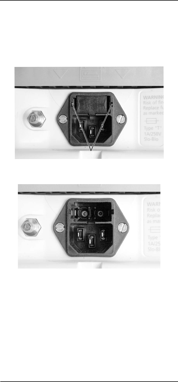
MEDRAD
Veris
8600
H-3
Fuse Removal/Replacement
Remote Display
There are two AC power fuses located at the rear of the remote
display directly above the AC power entry socket. Remote displays
use 1A 250V Slo Blo fuses.
1. Press in the side clips (at the same time) with a tool and lift out
the small, black access cover. The two fuse sockets are visible.
Figure H-1: Remove the Fuse Cover
Figure H-2: Fuses Exposed
Clips
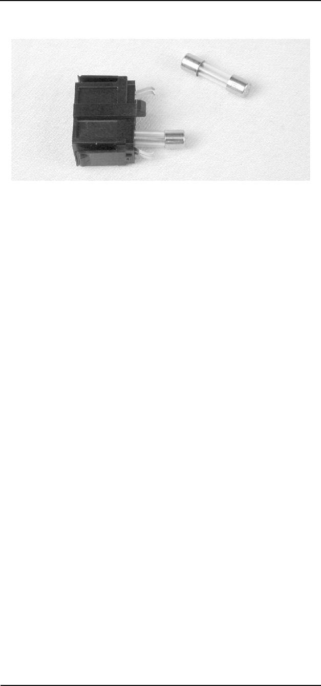
MEDRAD
Veris
8600
H-4
2. Gently pull the fuses out of the fuse cover assembly.
Figure H-3: Fuses Pulled
3. Reassemble in reverse order.
Power Supply
There are two AC power fuses located at the AC input side of the
power supply directly above the AC power entry socket. Power
supplies use 5A 250V slow acting fuses.
1. Pry the cover from the fuse well above the AC cord.
2. Gently remove the fuse assembly and remove the spent fuse(s).
3. Replace fuses and reassemble in reverse order.