Cross Match Technologies RJ0479 OPTICAL SCANNER WITH RFID User Manual
Cross Match Technologies GmbH OPTICAL DOCUMENT SCANNER WITH RFID Users Manual
Contents
- 1. Users Manual
- 2. Users Guide
Users Manual

Cross Match® Technologies, Inc.
D SCAN® AUTHENTICATOR CF™
Document Authentication Reader
User Manual
Version 2.0
Second Edition (March 2009)
Specifications are subject to change without prior notice.
Cross Match Technologies GmbH assumes no liability for maloperation or
improper use of products.
Cross Match® and D SCAN® are registered trademarks, and the CROSS
MATCH TECHNOLOGIES logo is a trademark of Cross Match
Technologies, Inc.
All other trademarks, brands and names are the property of their respective
owners and are protected by US and international copyright and trademark
laws.
No portion of this guide may be reproduced in any form or by any means
without the express written permission of Cross Match® Technologies.
© Copyright 2009, Cross Match Technologies. All rights reserved.

Contents i
Contents
Introduction
Appropriate Operation ...................................................................... 1-1
Who should read this book ................................................................ 1-1
How this book is arranged ................................................................. 1-1
Standards ....................................................................................... 1-2
FCC statement ................................................................................. 1-2
Industry Canada .............................................................................. 1-2
Statement of Compliance .................................................................. 1-3
Recycling information ....................................................................... 1-3
WEEE Directive ................................................................................ 1-3
Safety when operating ...................................................................... 1-3
Glossary ......................................................................................... 1-4
Installation
D SCAN AUTHENTICATOR CF ............................................................. 2-1
Front view ................................................................................... 2-2
Top of the document reader ........................................................... 2-3
Ambient light cover ................................................................... 2-4
Back view .................................................................................... 2-5
Product label ............................................................................ 2-6
System requirements ....................................................................... 2-6
Operating system ......................................................................... 2-6
Hardware .................................................................................... 2-6
Installation ...................................................................................... 2-7
Remove the contents .................................................................... 2-7
List of contents ............................................................................ 2-7
Prepare to use ............................................................................. 2-7
Connect the Authenticator CF ......................................................... 2-7
Starting the first time
System diagnosis ............................................................................. 3-1
Checking the system configuration .................................................. 3-2
Detailed document reader information ............................................. 3-4
Testing the user controls ............................................................... 3-4
Testing the RFID reader ................................................................ 3-5
Testing the reader unit .................................................................. 3-6
ii D SCAN® AUTHENTICATOR CF™ User Manual V2.0
Using the generated log .................................................................3-8
Creating background images ..............................................................3-9
Preparation ..................................................................................3-9
Procedure ....................................................................................3-9
How to use the Authenticator CF
Applications and software levels .........................................................4-1
Characteristics of documents ..............................................................4-2
The machine readable zone ............................................................4-3
Positioning of documents ...............................................................4-3
Read in a document ..........................................................................4-4
The Overview page .......................................................................4-5
The Images page ..........................................................................4-6
The RFID data page ......................................................................4-7
Maintenance
Cleaning ..........................................................................................5-1
Cleaning the document contact area ................................................5-1
Cleaning the case ..........................................................................5-2
Specifications ...................................................................................5-2
Problems and Corrections
The Authenticator does not work .....................................................6-1
Authenticator disconnected during operation .....................................6-1
Initialization failed .........................................................................6-2
Dark image sections ......................................................................6-2
Visualization and processing speed too slow .....................................6-2
Creating a problem report ..............................................................6-3
Customer Care and Contact Information
Technical Support .............................................................................7-1
E-mail .........................................................................................7-1
Telephone and facsimile .............................................................7-1
Return and repair of the Authenticator CF ........................................7-2
Delivery costs ..................................................................................7-2
The product is in the warranty period ...........................................7-2
The product is not in the warranty period .....................................7-3
Contact information ..........................................................................7-3
Corporate Headquarters .............................................................7-3
IGerman Operations ..................................................................7-3
Corporate Web Page ..............................................................7-3
Index

iii
Figures
Figure 2.1: D SCAN AUTHENTICATOR CF front view ...................................... 2-2
Figure 2.2: D SCAN AUTHENTICATOR CF instruction label .............................. 2-2
Figure 2.3: Top view of the D SCAN AUTHENTICATOR CF ...............................................2-4
Figure 2.4: Ambient light cover positions ........................................... 2-5
Figure 2.5: D SCAN AUTHENTICATOR CF back view ...................................... 2-5
Figure 2.6: D SCAN AUTHENTICATOR CF product label .................................. 2-6
Figure 2.7: D SCAN AUTHENTICATOR CF connection box ............................... 2-8
Figure 3.1: D SCAN TestWizard start screen ....................................... 3-2
Figure 3.2: System configuration page .............................................. 3-2
Figure 3.3: Device list page ............................................................. 3-3
Figure 3.4: Device overview page ..................................................... 3-4
Figure 3.5: User controls page ......................................................... 3-5
Figure 3.6: RFID reader test page ..................................................... 3-6
Figure 3.7: Image acquisition page ................................................... 3-7
Figure 3.8: Capture and save image page .......................................... 3-7
Figure 3.9: Tests completed page ..................................................... 3-8
Figure 3.10: Prepare the white test chart ......................................... 3-10
Figure 3.11: Placing the white test chart .......................................... 3-10
Figure 3.12: Image acquisition page ............................................... 3-11
Figure 3.13: Capture and save image page ...................................... 3-11
Figure 4.1: The machine readable zone ............................................. 4-3
Figure 4.2: Instruction label on the cover ........................................... 4-3
Figure 4.3: Positioning of a passport ................................................. 4-4
Figure 4.4: Overview page ............................................................... 4-5
Figure 4.5: Image page ................................................................... 4-6
Figure 4.6: RFID data page .............................................................. 4-7
Figure 5.1: Clean the document contact area ..................................... 5-1
iv D SCAN® AUTHENTICATOR CF™ User Manual V2.0

v
Tables
Table 1.1: Glossary of terms ............................................................ 1-4
Table 2.1: D SCAN AUTHENTICATOR CF major components .......................... 2-3
Table 2.2: D SCAN AUTHENTICATOR CF back view ....................................... 2-5
Table 5.2: Product specifications ....................................................... 5-2
Table 7.1: The Technical Support department addresses ...................... 7-1
Table 7.2: The Technical Support department numbers ........................ 7-1
Table 7.3: The addresses for product returns ...................................... 7-2
vi D SCAN® AUTHENTICATOR CF™ User Manual V2.0

Appropriate Operation 1-1
1
Chapter 0Introduction
Appropriate Operation
The D SCAN® AUTHENTICATOR CF is a full color image and full page reader
for the intended use of acquisition and transmission of personal and document
data. The device has the capability to capture images of an entire data page of any
ID document in different illuminations and to read RFID data contactless found
on the RFID chip.
It is intended for the use in IT-devices area and the operation and installation must
be in connection with suitable computer equipment. When operating, the
electrical installation and cabling must comply with the IEC 60950 standard.
Who should read this book
You should read this book if you are a user and you will be operating the D SCAN
AUTHENTICATOR CF document authentication reader device.
How this book is arranged
•Chapter 1 “Introduction” covers standards for the manual and describes
the safety instructions. The chapter also contains a glossary of terms.
•Chapter 2 “Installation” describes the D SCAN AUTHENTICATOR CF
and how to install the document authentication reader.
•Chapter 3 “Starting the first time” describes a tool that helps to perform a
complete interactive diagnosis of the document authentication reader and
how to create background images.
•Chapter 4 “How to use the Authenticator CF” describes how to use the
indicators on the device to capture the best quality images.
•Chapter 5 “Maintenance” explains how to maintain the D SCAN
AUTHENTICATOR CF.
•Chapter 6 “Problems and Corrections” describes the problems, causes,
and corrections.
•Chapter 7 “Customer Care and Contact Information” explains how to
get the technical support that is available from Cross Match Technologies.

1-2 D SCAN® AUTHENTICATOR CF™ User Manual V2.0
Introduction
Standards
The following standards are used in this book:
•Bold UPPER/lower case and tilted text identify important information.
• Special information can appear as a Note, Caution, Warning, or Danger.
Note
A Note contains additional information. To ignore a note can cause a delay, but not
mechanical damage or personal injury.
Caution
A Caution contains a method to prevent data loss or damage to equipment. To ignore the
caution can cause damage or data loss.
Warning
A Warning describes an action that can cause injury or loss of life. Mechanical damage can
occur.
DANGER
A Warning describes an action or condition that causes injury or loss of life. Mechanical
damage can occur.
FCC statement
FCC ID: WO8RJ0479
This device complies with Part 15 of the FCC Rules. Operation is subject to the
following two conditions:
(1) this device may not cause harmful interference, and
(2) this device must accept any interference received, including interference that
may cause undesired operation.
The power source for the AUTHENTICATOR CF must provide an output voltage
of 21 ±3 V DC. The electric current range of the power supply unit must be min. 1
A and max. 7 A. Use only power supply units that comply with the class B limits
of 47 CFR 15, Subpart B.
Industry Canada
IC: 7944A-RJ0479
This Class B digital apparatus complies with Canadian ICES-003. Operation is
subject to the following two conditions:
(1) this device may not cause interference, and
(2) this device must accept any interference, including interference that may cause
undesired operation of the device.
The power source for the AUTHENTICATOR CF must provide an output voltage
of 21 ±3 V DC. The electric current range of the power supply unit must be min. 1
A and max. 7 A. Use only power supply units that comply with the class B limits
of ICES-003.
Statement of Compliance 1-3
Introduction
Statement of Compliance
Cross Match Technologies GmbH, hereby, declares that this device is in
compliance with the essential requirements and other relevant provisions of
Directives 89/336/EEC and 2006/95/EC.
Declaration of Conformities may be directly obtained from Cross Match
Technologies GmbH.
Recycling information
Cross Match Technologies recommends that customers dispose of their used
computer hardware, monitors, printers and other peripherals in an
environmentally sound manner. Potential methods include reuse of parts or whole
products and recycling products, components and/or materials.
WEEE Directive
The following is the test of the Waste Electrical and Electronic
Equipment (WEEE) Directive.
In the European Union, this label indicates that this product should
not be disposed of with household waste. It should be desposited at
an appropriate facility to enable recovery and recycling.
Safety when operating
This product has been designed, manufactured and tested according to
international safety standards. The following general safety precautions must be
observed during all phases of operation to ensure safe operation of the D SCAN
AUTHENTICATOR CF. Cross Match Technologies GmbH assumes no liability
for the customer's failure to comply with these requirements.
• When operating, the electrical installation and cabling must comply with the
IEC 60950 standard.
• The power supply must be provided by an certified power supply unit with
an output voltage of 21 ±3 V DC. The electric current range of the power
supply unit must be min. 1 A and max. 7A. Use the desktop power pack
which is provided with the product package.
• To connect the document reader to a computer, use a shielded USB data
cable as supplied with the reader.
• The device must be operated only in a dry room. Exclude any condensation.
• The environmental temperature range is 50°F to 113°F (10°C to 45°C).

1-4 D SCAN® AUTHENTICATOR CF™ User Manual V2.0
Introduction
Caution
Do not open the device. Repairs are only allowed by Cross Match Technologies. Changes
or modifications not expressly approved by Cross Match Technologies could void the user's
authority to operate the equipment.
• Whenever it is likely that the electrical protection has been compromised, the
device and system must be made unplugged and secured against
unauthorized use.
• Do not apply mechanical stress to the document contact area. Do not throw
heavy objects onto it. The platen is made of glass and might be destroyed if
not handled properly. A broken platen might have sharp edges, which could
cause injuries.
• Do not scratch the document contact area. The platen is vulnerable to sharp
metallic instruments (knives, scissors), extremely hard objects (diamonds)
and also dust. Scratches may reduce the image quality and thereby lead to
scanning results below the required quality specification.
• Always keep the document contact area clean. Use the recommended glass
cleaner and lint-free tissue for cleaning. Do not use oily or abrasive cleaners
since they might affect the platen surface quality.
• Do not pour liquids (water etc.) onto the D SCAN AUTHENTICATOR CF.
The device is protected against cleaning with a damp cloth or tissue,
however, it is not waterproof.
Warning
Do not look directly into the lights of the document contact area. Maintain a required
minimum distance of not less than 0.3 meters.
Glossary
This section contains some terms that are used in this manual.
Table 1.1
Glossary of terms
Term Definition
Barcode A means of storing data as a pattern of lines or dots.
DIN Deutsches Institut für Normung e.V. und deutsche Industrie-
Norm (German Institute for Standardization and Industrial
Standard Specification). Contains the fundamental standards for
many products of the industry.
DSE D SCAN Essentials.
Base level software for the D SCAN AUTHENTICATOR CF,
which runs on the external computer and support:
• USB driver
• Low level access to available illuminations, camera, and
RFID reader (APDU) via SDK
• Human interface control

Glossary 1-5
Introduction
DSM D SCAN Master. Optional middleware software which supports:
• High level document access (optical and RFID) including
workflow support, cryptographic protocols, and OCR
• Optional SDKs for both software levels
• Optional document definitions for customer specific
documents
• Optional development support
• Supports future upgrade of firmware and software
DSX D SCAN Extensions. Optional middleware software which
supports:
•
ERZ Effective Reading Zone.
Fixed dimensional area, common to all MRTDs, in which the
machine readable data in the MRZ can be read by document
readers.
ePassport
(eMRP or
Electronically
enabled MRP)
A machine readable passport (MRP) containing a Contactless
Integrated Circuit (IC) within which is stored data from the MRP-
data page, a biometric measure of the passport holder and a
security object to protect the data with PKI cryptographic
technology, and which conforms to the specification of Doc 9303,
Part 1.
IATA International Air Transport Association.
Is an international industry trade group of airlines headquartered
in Montreal, Quebec, Canada (where the ICAO also happens to
be headquartered, even though they are different entities).
On behalf of its Members and the entire aviation industry, IATA
works to ensure that new and enhanced security measures are
effective, internationally harmonized and minimize disruption to
passengers and shippers.
ICAO Doc 9303 International Civil Aviation Organization.
The International Civil Aviation Organization (ICAO) has taken a
leading role in the creation of machine readable travel documents
(MRTDs) in co-operation with the International Standardization
Organization (ISO). The Standards are contained in document
9303 of the ICAO.
IR Infrared radiation or light is an invisible electromagnetic radiation
that has a longer wavelength than visible light and is detected
most often by its heating effect. Infrared describes the part of the
electromagnetic spectrum with wavelengths between 700 nm
and 1mm. Near infrared light is closest in wavelength to visible
light and far infrared is closer to the microwave region of the
electromagnetic spectrum. Infrared light has many technology
and physics applications.
Table 1.1
Glossary of terms
Term Definition

1-6 D SCAN® AUTHENTICATOR CF™ User Manual V2.0
Introduction
Kensington
Security Slot Also called a K-Slot or Kensington lock, is a small hole found on
almost all small or portable computer and electronics equipment,
particularly on expensive and relatively light ones. It is used for
attaching a lock, in particular those from Kensington Computer
Products Group, who are its originators.
Locks are generally secured in place with a key or some
mechanical PIN device and attached through a rubberized metal
cable. The end of the cable has a small loop which allows the
whole cable to be looped around a permanent object, such as a
heavy table or other similar equipment, thus securing it in place.
LED Light Emitting Diode.
Semiconductor which emits light if connected to voltage.
MRTD General Term for all Machine Readable Travel Documents.
Official document issued by a State or organisation which
conforms to ICAO Doc 9303 specifications and which is used by
the holder for international travel (e.g. passport, visa, MRtd) and
which contains mandatory eye readable data and a separate
mandatory data summary in a format which is capable of being
read by machine..
MRZ Machine Readable Zone.
Fixed dimensional area located on the MRTD, containing
mandatory and optional data formatted for machine reading
using OCR methods.
OCR Optical Character Recognition.
It is the mechanical or electronic translation of images of
handwritten or typewritten text on paper into machine-editable
text. It is scanned with a computer (NCI) and converted to an
editable text document (CI). OCR is already being used widely in
the legal profession, where searches that once required hours or
days can now be accomplished in a few seconds.
OCR-font OCR font is the term given to a set of special typeface style
developed for Optical Character Readers and Optical Character
Recognition software. Each character within a font will have a
defined reproducible size and shape. For OCR, these are defined
by ISO 1073-II and although use of OCR-B is preferred.
OCR fonts are standardized and designed to be both machine
and human readable. Some examples of OCR implementations
include bank checks, passports, serial labels and postal mail.
RFID Radio Frequency Identification (RFID) is a method of identifying
unique items using radio waves. Typically, a reader
communicates with a tag, which holds digital information in a
microchip. But there are chipless forms of RFID tags that use
material to reflect back a portion of the radio waves beamed at
them. As well as the standard passport data already included,
this can also be used to store biometric features. The basic
technical specifications of the RF chip for use in passports have
been standardized by the ICAO.
Table 1.1
Glossary of terms
Term Definition

Glossary 1-7
Introduction
Smart card A smart card, chip card, or integrated circuit card (ICC), is
defined as any pocket-sized card with embedded integrated
circuits which can process information. The card is made of
plastic, generally PVC, but sometimes ABS or polycarbonate.
The card may embed a hologram or other security features to
avoid counterfeiting. Smart cards are defined according to the
card data read and wright features and the type of chip implanted
within the card. There is a wide range of options.
The most common type of smart card is the contact Smart card
where electrical contacts located on the outside of the card
connect to a card reader when the card is inserted. Contact
Smart cards are standardized in ISO/IEC 7816.
Contactless smart cards employ a radio frequency (RFID)
between card and reader without physical insertion of the card.
Instead the card is passed along the exterior of the reader and
read. Contactless Smart cards are standardized in ISO/IEC
14443.
UV Ultraviolet (UV) light is represented in the light spectrum as light
with a wavelength of 200nm to 400nm. The UV spectrum is
divided into three regions: the near ultraviolet, the far ultraviolet,
and the extreme ultraviolet, all of which are present in natural
sunlight. These waves are invisible to the human eye.
VIZ Visual Inspection Zone.
Those portions of the MRTD (data page in the case of MRP)
designed for visual inspection, i.e. front and back (where
applicable), not defined as the MRZ.
Table 1.1
Glossary of terms
Term Definition
1-8 D SCAN® AUTHENTICATOR CF™ User Manual V2.0
Introduction

D SCAN AUTHENTICATOR CF 2-1
2
Chapter 0Installation
T
HIS
CHAPTER
DESCRIBES
THE
D SCAN AUTHENTICATOR CF
AND
HOW
TO
INSTALL
THE
DOCUMENT
AUTHENTICATION
READER
.
D SCAN AUTHENTICATOR CF
The compact single step full page document reader D SCAN AUTHENTICATOR
CF (CF stands for Compact Full page) is the newest and smallest member of the
D SCAN AUTHENTICATOR product family. Some of the following
characteristics require additional software functions which might be contained in
D SCAN Master or project specific.
The document authentication reader has the following characteristics:
• Capability to capture images of an entire data page of an ID document and to
read RFID chip data contactless using a 13.56 MHz RFID Transceiver.
• Reads RFID and optical data of an ID document in one step without
repositioning of the document, One Step scanner.
• The additionally installed card reader provides a contact interface, which
allows to read the chip data of ID cards.
• Allows to check the authenticity of security elements of ID documents by
comparing the differently lit images (visible, IR and UV light).
• High speed data capture and transmission using the USB 2.0 interface.
• Its single RFID antenna covers the entire document contact area, so the
reading function is independent from position of the chip inside the
document.
• The extra large optical scanning area allows inspection of documents
without removing their protective cover.
• It can be configured to perform all scanning and checking functions in a
fully automatic mode without any operator intervention.
• No moving parts and optional high-performance LED UV illumination
ensure maximum reliability.
• The D SCAN AUTHENTICATOR CF complies with ISO standards and
achieved excellent results in recent ICAO interoperability tests in Japan and
2-2 D SCAN® AUTHENTICATOR CF™ User Manual V2.0
Installation
Singapore in 2005, and in Germany in 2006, where they were able to read all
presented passports.
• The operation and display of results is controlled by a special software as
well as all functions.
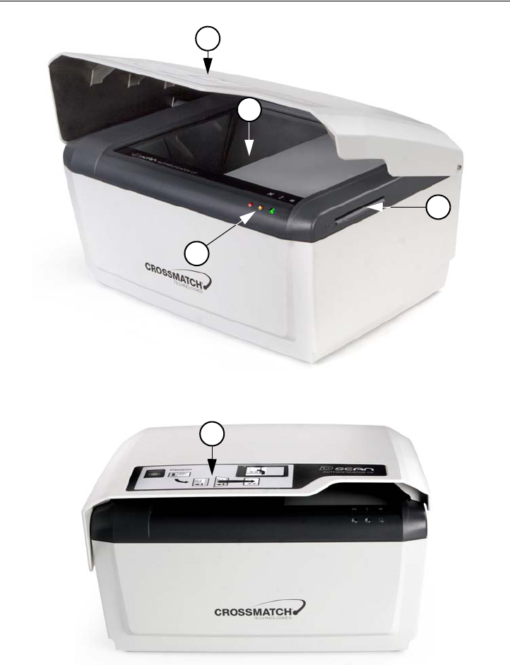
Front view
Figure 2.1
D SCAN AUTHENTICATOR CF front view
Figure 2.2
D SCAN AUTHENTICATOR CF instruction label
1
4
2
3
5

D SCAN AUTHENTICATOR CF 2-3
Installation
Top of the document reader
The following section contains important details of the top of the device with a
brief description of each. The ambient light cover has been opened to better show
the details.
Table 2.1
D SCAN AUTHENTICATOR CF major components
#Description
1Ambient light cover. The height adjustable cover is used as a mask to reduce
outside light during operation and protects the document contact area when the
device is not in use.
2Document contact area. The glass bearing surface where documents are
placed to be verified. It is divided into the optical scan area and the document
support area. The entire document contact area is covered by the RFID antenna.
3Smart Card slot. The integrated contact smart card reader allows maximum
application comfort and is able to read cards according to ISO 7816 protocol
Type T=0 (asynchronous half duplex character transmission protocol) and
T=1 (asynchronous half duplex block transmission protocol).
4Status LEDs and Buzzer. Three LEDs can provide visible indications and a
volume adjustable buzzer provides acoustical indication to the user about the
current mode of the document reader.
Using the D SCAN Master application the LEDs light as follows:
The backlit red light is the Status light and lights during the initialization process
or when the device is not ready for operation.
The backlit yellow is the Processing light and lights when processing a
document. During this time, no other documents can be verified. After
processing it turns off, indicating that a new authentication can be started.
The backlit green is the Operation light and lights after the device is
successfully initialized and when an authentication is completed.
Other programs can use the lights and the buzzer in different methods.
5 Instruction label. The label informs the user in principle how to position and
place a document correctly.
2-4 D SCAN® AUTHENTICATOR CF™ User Manual V2.0
Installation
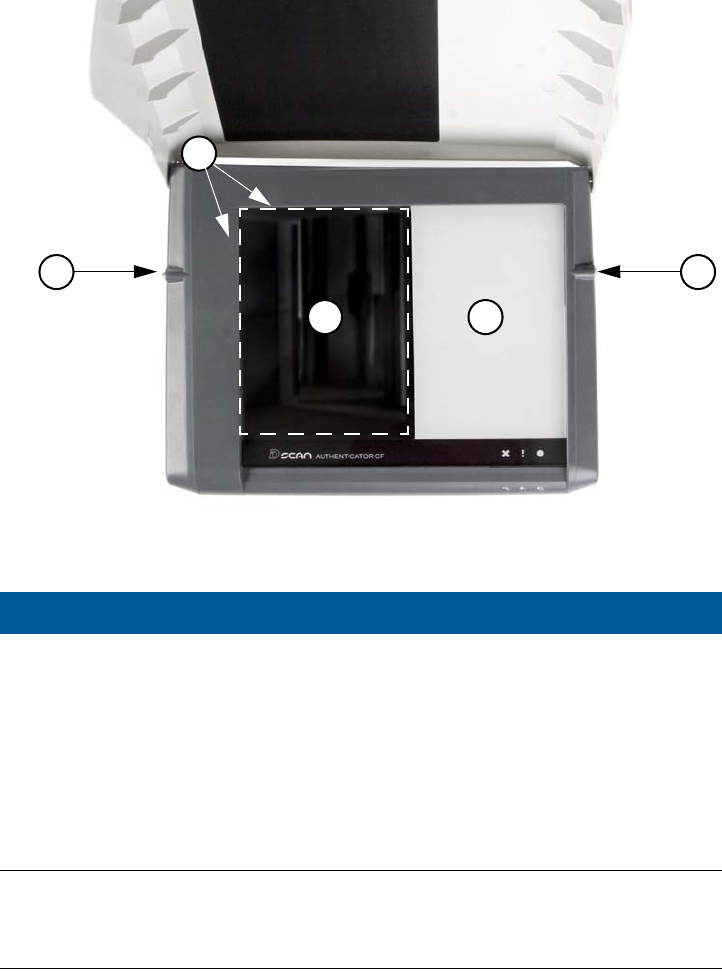
Figure 2.3
Top view of the D SCAN AUTHENTICATOR CF
Ambient light cover
The cover is pivoted by two bolts, one on each side, at the upper back of the
D SCAN AUTHENTICATOR CF. This allows a three-point positioning, closed
(1), operating (2) and opened (3). To move the cover in one of these position lift it
at the front edge. Two ball catches hold the cover in the operating position.
#Description
1Document positioning angle. The document positioning angle helps to
guarantee the exact final position of the document for authentication.
2Optical scan area. The glass bearing surface where documents are placed to be
verified. A dotted line shows the area of optical reading.
3Document support area. The part of the glass bearing surface which is not used
for scanning. It supports positioning larger documents correctly and is also
covered by the RFID antenna.
4Ball catches. One ball catch is located on each side of the document contact
area.
1
2
4 4
3
D SCAN AUTHENTICATOR CF 2-5
Installation
Figure 2.4
Ambient light cover positions
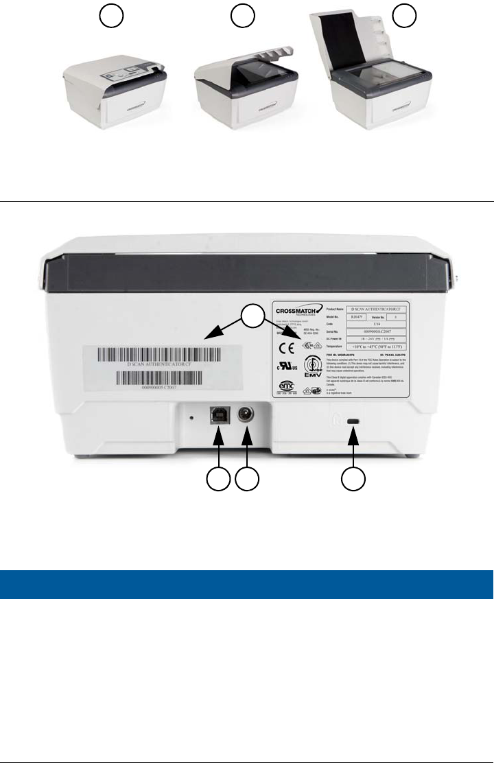
Back view
Figure 2.5
D SCAN AUTHENTICATOR CF back view
Table 2.2
D SCAN AUTHENTICATOR CF back view
#Description
1USB-A connector. The USB 2.0 high speed interface cable connects the
Authenticator to the computer and delivers the reading data to the computer.
2Power connector. Connects the power source to the computer and supplies 19
VDC to operate the document reader.
3Kensington security slot. Used to secure the unit in place with a key and
attached through a rubberized metal cable. The end of the cable has a small loop
which allows the whole cable to be looped around a permanent object, such as a
heavy table or other similar equipment, thus securing it in place.
4Device labels. Shows manufacturer and product information.
1 2 3
1 2 3
4
2-6 D SCAN® AUTHENTICATOR CF™ User Manual V2.0
Installation
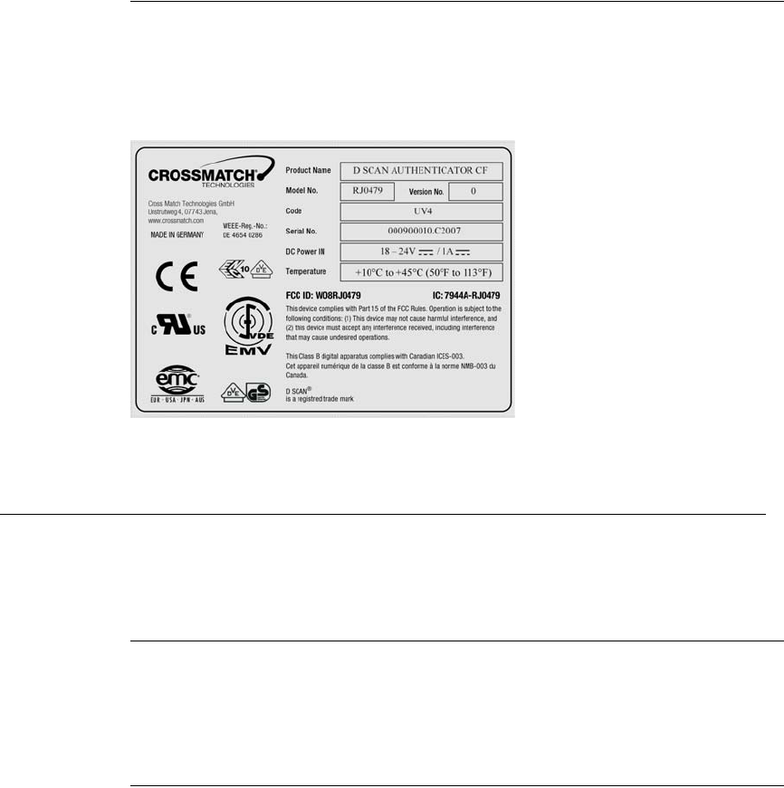
Product label
A label on the back of the device contains information on Manufacture, Product
Name, Model Number, Code Number, Serial Number, Connection Values, FCC
Compliance, CE Compliance and other Certification Symbols. The field Code can
contain the abbreviation UV4, which indicates that the optionally ultraviolet
illumination is installed:
Figure 2.6
D SCAN AUTHENTICATOR CF product label
System requirements
The D SCAN AUTHENTICATOR CF can be connected to a computer using the
USB 2.0 High Speed interface. This section describes the minimum system
requirements for the document reader.
Operating system
• Windows XP Professional, Service Pack 2
• Microsoft .NET Framework 1.1 should be installed
• D SCAN Essentials Runtime
Hardware
The minimum requirements applies to desktop and laptop computers.
• 2 GHz or higher processor with SSE2 instruction set (Intel Pentium 4 or
Celeron or better, or AMD Athlon64 or better)
•1 GB RAM
• 100 MB free hard drive space
• USB2.0-compliant ports or USB 2.0 PCI/PCMCIA card
• 1024 x 768 Video-Resolution monitor

Installation 2-7
Installation
Installation
This section describes how to install the D SCAN AUTHENTICATOR CF.
Remove the contents
Note
Keep all original materials in the event you return the document reader.
Remove all the contents from the product package.
List of contents
The following items are included in the product package:
• D SCAN AUTHENTICATOR CF document authentication reader
• External power supply unit
• USB A-B signal cable
• D SCAN Essentials Runtime CD
• D SCAN AUTHENTICATOR CF User Manual on CD
• White/yellow test chart (creation of background images ????)
Prepare to use
Make sure that the following conditions exist before you use the D SCAN
AUTHENTICATOR CF.
• After transportation or storage at low temperature, allow the reader to
adjust to the temperature at the location of operation.
• Store the document reader in a warm dry location.
• The product is on a level surface.
• The surface of the document contact area is clean and dry.
• Protect the document reader from dust and humidity.
• Keep all sharp and pointed objects away from the document contact area
surface.
Connect the Authenticator CF
Note
Before you begin, ensure that the device reached room temperature before powering on the
device. The procedure applies to desktop and laptop computers.
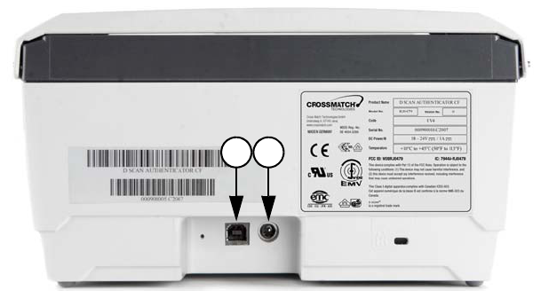
The connectors are on a connection box at the back of the device. Use the
following procedure to install the D SCAN AUTHENTICATOR CF USB and
power cables.
1 Put the device on a clean flat area like a table, that is free of dust.
2 Slightly lift the back of the device. You see the connection box with the power
(2) and USB (1) connectors.
3 Get the USB and power cables.
2-8 D SCAN® AUTHENTICATOR CF™ User Manual V2.0
Installation
4 Insert the cable connectors into their related connectors in the connection box.
Figure 2.7
D SCAN AUTHENTICATOR CF connection box
5 Connect the power supply to the AC electrical outlet.
• All LEDs should quickly flash on and off. The orange LED comes on again
flashing indicating the standby mode.
Note
When the power is applied to the D SCAN AUTHENTICATOR CF, it is permanently powered
on. Unplug the device from the AC electrical outlet, if you want to completely power-down
the device.
6 Connect the other end of the USB cable to the USB 2.0 port of your computer.
7 You have completed the procedure.
Note
Before you connect the D SCAN AUTHENTICATOR CF to the USB port of your PC you
must install the D SCAN Essentials software, which copies all the required hardware driver
files into the same directory, where they can be easily accessed during the D SCAN
AUTHENTICATOR CF installation.
You can use any USB port when plugging in the D SCAN AUTHENTICATOR
CF. However, the first time you plug the device into a particular port, Windows
will install the driver for that device again. The Found New Hardware message is
displayed in the notification area, at the far right of the taskbar or the Found New
Hardware Wizard starts automatically.
21

System diagnosis 3-1
3
Chapter 0Starting the first time
T
HIS
CHAPTER
DESCRIBES
A
TOOL
THAT
HELPS
TO
PERFORM
A
COMPLETE
INTERACTIVE
DIAGNOSIS
OF
THE
DOCUMENT
AUTHENTICATION
READER
AND
HOW
TO
CREATE
BACKGROUND
IMAGES
.
Separate software tools that support the identification and diagnosis of technical
problems are provided as part of the D SCAN Essentials software packages.
The D SCAN TestWizard tool can be used for both to complete an interactive
diagnosis of the system and the document reader and to capture and save
background images. It is designed for easy operation and does not require special
knowledge. The program guides the user through several step-by-step diagnostic
procedures.
Before you operate any D SCAN AUTHENTICATOR CF the first time and you
install a new computer connected to the device you should perform:
• A complete diagnosis of the system and the document reader to identify that
the system works properly and no installation problems occurred.
• Creating background images for the installed IR and visible light
illumination to adjust the device to the conditions of the place of operation.
Note
For a device which is returned from service you must also perform a complete diagnostic of
the document reader and create new background images. Replace the previously used
background images.
System diagnosis
The test sequence covers test procedures start everything from the beginning,
where the document reader and all driver software is not initialized yet till the end
and finish when all components have been checked.
1 Power on the D SCAN AUTHENTICATOR CF and switch on your computer.
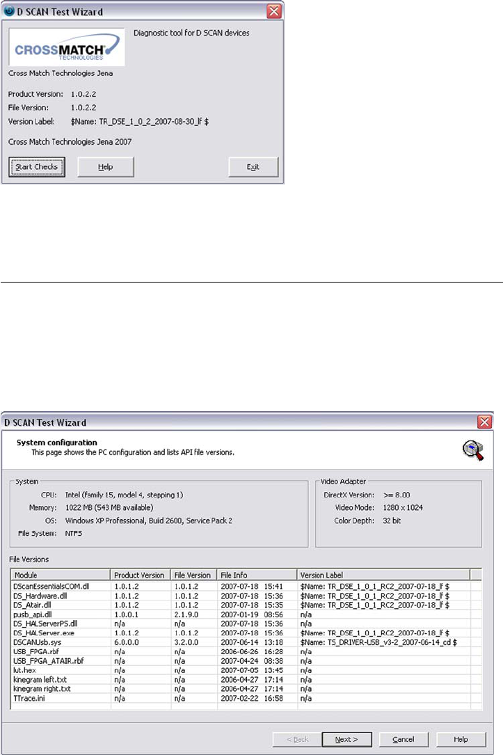
2 Start the D SCAN TestWizard by clicking the icon on the desktop or select
Start/ProgramFiles/Cross Match Technologies/D SCAN
Essentials/D SCAN TestWizard
.
• The program starts with a version information dialog. This is the starting
point for every test procedure.
• You can view the User Guide for this software by clicking Help.
3-2 D SCAN® AUTHENTICATOR CF™ User Manual V2.0
Starting the first time
Figure 3.1
D SCAN TestWizard start screen
3 Click Start Checks... to start the system configuration test sequence.
Checking the system configuration
The first step in the sequence is an automatic analysis of such system resources as:
• CPU type and details,
• PC main memory (RAM),
• Operating system and File system
• Screen resolution, color depth
• and Current versions of the software components.
Figure 3.2
System configuration page
System diagnosis 3-3
Starting the first time
Caution
This information is important to ensure the proper operation of the whole system. Especially
when selecting and configuring a new PC, since incorrect resources can cause slow
performance, wrong data and even crashes.
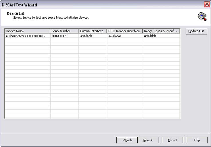
1 Clicking Next starts the Device List page. This page lists all detected devices
connected to the PC and showing the Device Name, the Serial Number, and the
available interfaces of the document reader.
Figure 3.3
Device list page
2 Use the mouse cursor and highlight the desired device before clicking Next to
start the initialization of the device.
• After waiting a few seconds, completion of the document reader
initialization is signaled to you by displaying the Device Overview page.
If the initialization fails, you will see an error message that describes the nature of
the problem.
• In the case the TestWizard cannot find the required information in its
configuration files click the button Update. It starts a re-scan for all USB
ports of the PC. Only devices which are supported by the D SCAN Essentials
version are listed accordingly.
• Alternatively click Back to return to the System Configuration page and
repeat the device identification.
Note
For error code definitions click
Help
and refer to the section File List of the help document.
3-4 D SCAN® AUTHENTICATOR CF™ User Manual V2.0
Starting the first time
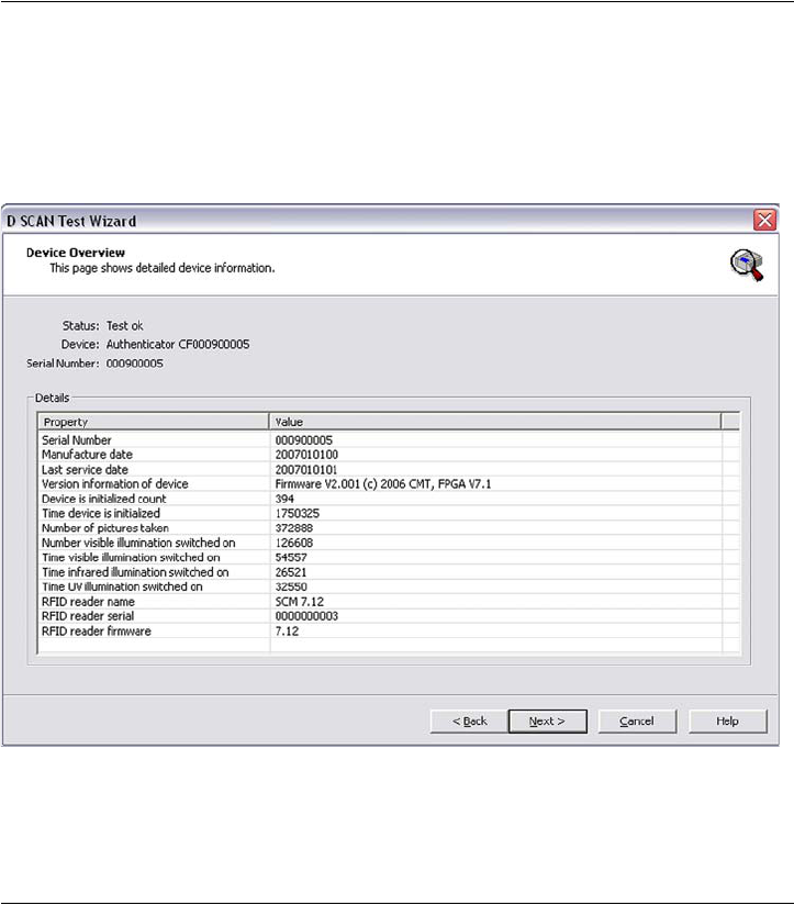
Detailed document reader information
After successful initialization, the Device Overview page appears, showing you
the following information about the document reader connected to your computer.
• The device type, serial number and initialization status,
• Firmware and revision version,
• Production date and last service,
• Operating times and some more properties
Figure 3.4
Device overview page
1 After reading this information click Next to start the User Controls page.
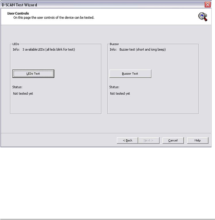
Testing the user controls
The User Controls page shows all available user controls supported by your
document reader and allows to check its LEDs and the available beeper (tunes).
Because that the D SCAN AUTHENTICATOR CF has no control elements the
LEDs test button is selected per default for testing.
1 Click LEDs Test to start the test procedure for the status LEDs. A default test
pattern will be executed illuminating the LEDs in sequence.
2 To test the buzzer click Buzzer Test.
Note
You must perform both tests to activate the button
Next
.
System diagnosis 3-5
Starting the first time
Figure 3.5
User controls page
Note
A physical defect LED or beeper cannot be detected automatically. It is necessary to
observe the test patterns to identify any malfunction or defect manually. An observed
malfunction should be added manually to the log file as a Comment at the Tests Completed
Page.
3 Click Next to finish the test session. The RFID reader page appears.
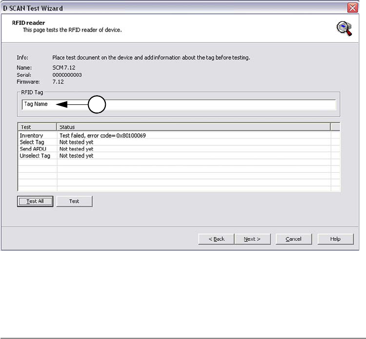
Testing the RFID reader
The document reader contains a RFID reader, which is able to communicate with
RFID chips. By examining the document reader properties you are able to test it.
•The RFID reader page shows a list of all available RFID tests containing
Tests and Status information.
• The tests can be performed either as single tests separately or testing all in
sequence by using the buttons Test or Test All.
1 Enter the Tag Name (1) of the document, which is placed for testing.
2 Testing all modes is the default setting where all communication tasks will be
performed. Start the test routine by clicking Test All.
•The column Status shows which test will be performed and whether the test
was successful. Not successfully tests displaying an error number.
• Experienced users are able to perform single tests. To do so, highlight the
desired test item using the mouse cursor and click the button Test to start the
test.
3-6 D SCAN® AUTHENTICATOR CF™ User Manual V2.0
Starting the first time
Figure 3.6
RFID reader test page
3 After completing click Next to continue the test session. The Image Acquisition
page appears.
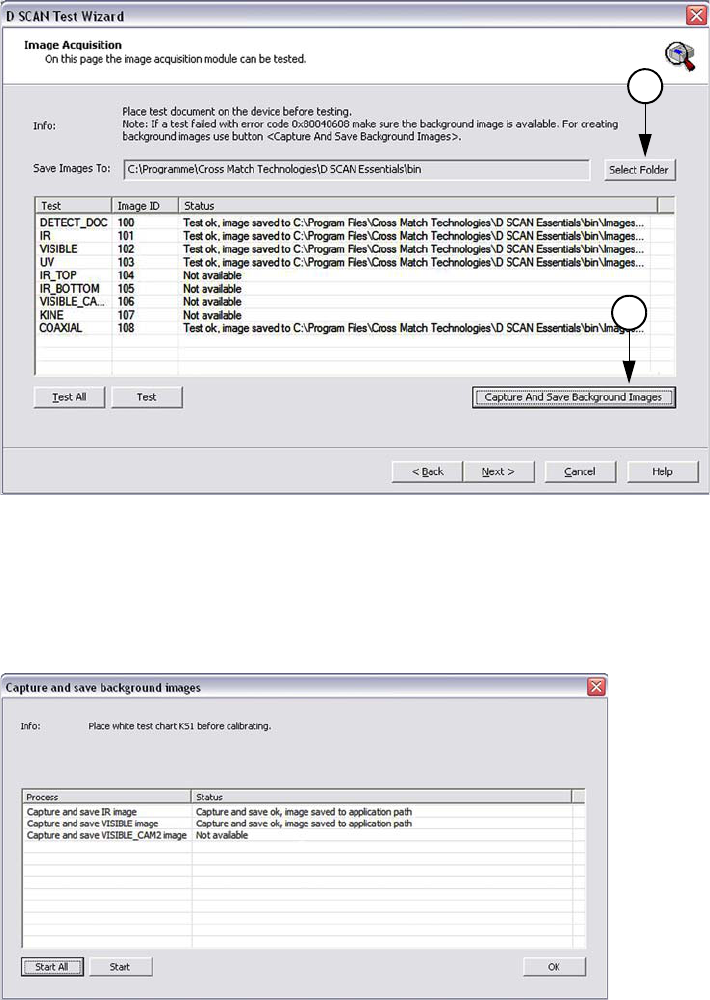
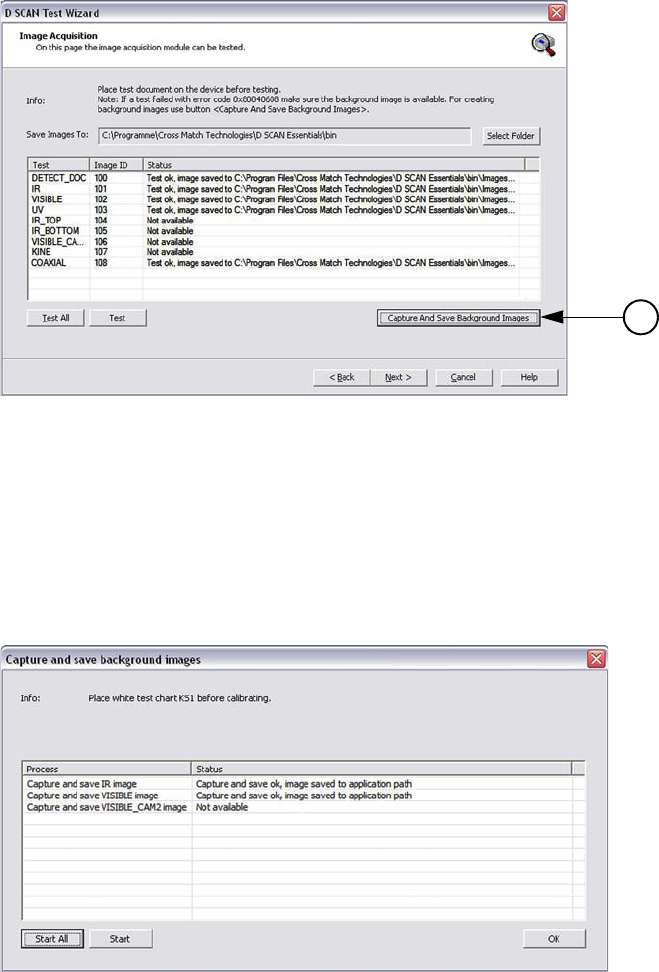
Testing the reader unit
The document reader contains a digital camera, which is able to work for
capturing images with different illuminations. By examining the document reader
properties you are able to test all supported image types.
•The Image Acquisition page shows a list of all available image types
containing the Test, the Image ID, and Test Status information.
• At the top of the list some important information are shown concerning the
test procedure and where the test images can be saved. To change the default
location click Select Folder (1) and choose the location where the images
are to be stored. The test images may be required for the technical support
department to correct problems.
• The tests can be performed either as single tests for each image type
separately by using the button Test or testing all capture modes in sequence
using Test All. For single tests highlight the desired capture mode using the
mouse cursor.
• Double-clicking a test image in the list opens the implemented image viewer
allowing you to check the image quality.
Note
Before testing the capture modes clean the glass platen of the document reader. A clean
platen is required for proper operation.
1
System diagnosis 3-7
Starting the first time
•The column Status shows which capture mode will be tested and whether the
test was successful. Not successfully tests displaying an alphanumerical
information.
Figure 3.7
Image acquisition page
• Clicking the button Capture and Save Background Images (2) at the right
side below the list opens a separate page. This page allows capturing and
saving background images. The list shows all supported image types and the
status of the tests.
Figure 3.8
Capture and save image page
1
2
3-8 D SCAN® AUTHENTICATOR CF™ User Manual V2.0
Starting the first time
• Using the function buttons is similar to the procedures described above for
the Test buttons.
• For more details how to create background images see section “Creating
background images” on page 3-9.
• To close the Capture and Save page click OK.
• After completing all tests click Next to finish the test session. The Tests
Completed page appears.
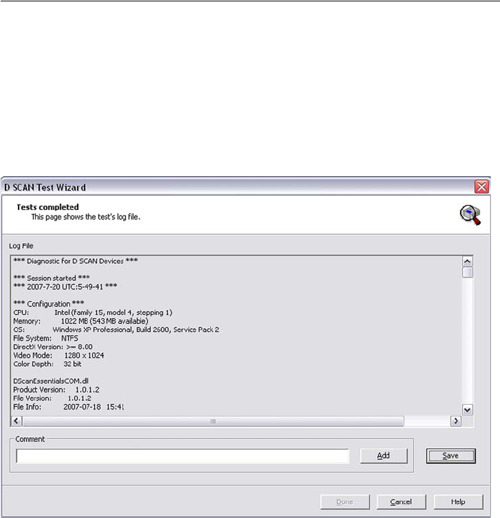
Using the generated log
All results retrieved from the system during these tests are displayed on the Tests
Completed page in a text window, and are also stored in a log file. This log file
must be stored on the system or on removable media.
This log file is important to understand the status and symptoms of a possibly
defective document reader, especially when trying to solve problems using remote
support.
1 At the bottom of this page the box Comments is located. Enter any individual
remarks or observed malfunction in this box and click the button Add. This
writes the comment to the end of the log file.
Figure 3.9
Tests completed page
2 Click Save, enter a file name and choose the location where the log file is to be
stored.
3 Click Done closes the Tests Completed page and moves to the Test Wizard
Startup screen.

Creating background images 3-9
Starting the first time
4 Click Exit to close the D SCAN TestWizard.
The service technician must save this log file to send it to the responsible service
or support center. This log file also contains the document reader serial number
and the firmware version number.
These two pieces of information are among the most important for tracking
problems. If the document reader cannot be operated (for example, due to a
defective power supply), then the service person must record the serial number
from the document reader´s back side manually.
Creating background images
The background correction images created during the factory calibration of the
device cannot be stored into the device. Therefore it is necessary to create
background images at the place of the intended operation for each D SCAN
AUTHENTICATOR CF device.
Creating background images is required when:
• A new or returned from service D SCAN AUTHENTICATOR CF device
will be installed at the place of operation.
• The computer where the D SCAN AUTHENTICATOR CF is connected will
be replaced by an other or a new one.
• You will operate a document reader, if it is returned from service. Replace
the previously used background images.
Preparation
Make sure that the following conditions exist before you perform the procedure.
• Clean the document contact area of the D SCAN AUTHENTICATOR CF
and allow the surface to dry. See “Cleaning” on page 5-1.
• Take the test chart from the product package and keep it in place.
• Power on the D SCAN AUTHENTICATOR CF and switch on your
computer.
• Start the D SCAN TestWizard and open the Image Acquisition page.
Procedure
Use the following procedure to capture and save background images.
1 Hold the test chart by the edges.
Note
Do not touch the white side of the test chart.
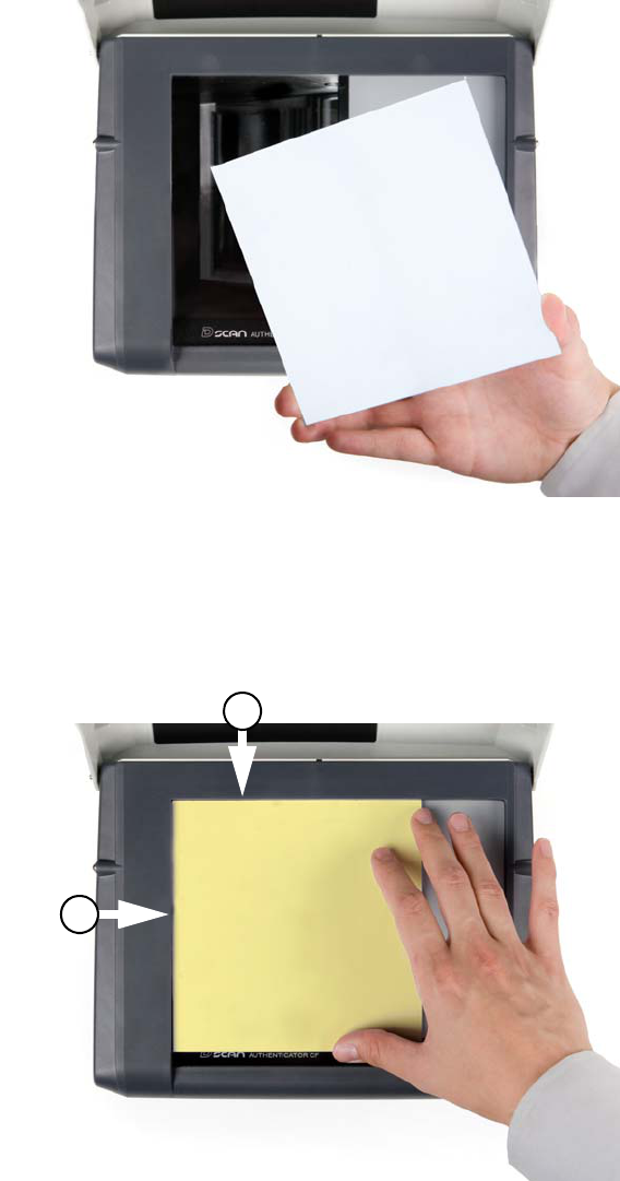
3-10 D SCAN® AUTHENTICATOR CF™ User Manual V2.0
Starting the first time
Figure 3.10
Prepare the white test chart
2 Put the test chart on the document contact area so that the white side faces down
to the glass platen and position it along the left (L) and the back (B) part of the
document positioning angle. The yellow back side of the test chart must
pointing to the top.
Figure 3.11
Placing the white test chart
L
B
Creating background images 3-11
Starting the first time
3 Move the ambient light cover in the operating position.
4 On the Image Acquisition page click Capture and Save Background Images
(2). The appearing separate page allows capturing and saving background
images.
Figure 3.12
Image acquisition page
• The top of the page shows an information to remind you that the white test
chart must be used.
• The background images can be performed either as single steps for each
image type separately by using the button Start or as complete steps in
sequence using Start All. For single steps highlight the desired image type
using the mouse cursor.
•The column Status shows whether a saved image was successfully created.
Figure 3.13
Capture and save image page
2
3-12 D SCAN® AUTHENTICATOR CF™ User Manual V2.0
Starting the first time
5 After completing click OK to close the page and close the TestWizard.
6 Remove the white test chart and store it on a save place for further use. Protect
the unprotected side with a soft cloth to avoid dirt and damages.
7 You have completed the procedure.
The created background images are stored on the computer connected to the D
SCAN AUTHENTICATOR CF in the Folder \bin of the D SCAN Essentials root
directory using the following syntax:
S/N of the device (9 digits)_IMT_image type.png
(example: 000000001_IMT_IR.png)
Note
Background images are related to the device for which they was created and cannot applied
to other devices.

Applications and software levels 4-1
4
Chapter 0How to use the
Authenticator CF
T
HIS
CHAPTER
DESCRIBES
THE
FIELDS
OF
APPLICATION
,
THE
CHARACTERISTICS
OF
DOCUMENTS
AND
HOW
TO
READ
A
DOCUMENT
WITH
THE
D SCAN AUTHENTICATOR
CF
USING
THE
D SCAN M
ASTER
DEMO
APPLICATION
.
Applications and software levels
The D SCAN AUTHENTICATOR CF is available with two software levels, the
D SCAN Essentials and D SCAN Master to allow easy integration into existing
systems on different levels of completeness. Each software level exists as a
runtime license and a SDK license.
The D SCAN Essentials runtime software is provided for every document reader
and is necessary for accessing D SCAN AUTHENTICATOR devices on a
fundamental functional level for high level document authentication software
from D SCAN Master series as well as for direct device access by system
integrators.
D SCAN Essentials software allows low level access to the device:
•USB driver
• Illumination selection and turn on/off, image capturing, RFID reader access
on APDU (Application Protocol Data Unit) level
• Human interface control (buzzer and status LEDs)
• Optional SDK recommended for system integrators with experience in
document processing.
D SCAN Master software allows high level functionality:
• Business method level to access images
• Verification of security features and RFID access on data group level
• OCR functionality and internal implementations of cryptographic protocols
• ICAO Doc 9303 default document definition
• Optional SDK with tools for the implementation of protocols like BAC,
EAC, PA, and AA

4-2 D SCAN® AUTHENTICATOR CF™ User Manual V2.0
How to use the Authenticator CF
Using the D SCAN Master software and/or additional customized functions the
following main applications, without the demand of completeness are:
Airports
• Airline check-in and boarding, automated check-in
• ID verification at the time of check-in
• Creation of reference data for passenger tracking
• Faster, more precise and more efficient passenger handling
Rental car companies
•Check-in
• Verification of ID documents
• Verification of driver’s licenses
• Automated check-in for pre-registered customers
Banks
• Verification of ID documents
• Search against blacklists
• Transaction automation
Hotels
•Check-in
• Automated check-in for pre-registered guests
• Reading personal data from ID documents of guests and transmitting to
authorities
Border control
• Automated border control
• Authentication of ID documents
• Providing reliable and efficient border control
Mobile Communications
• ID verification of customers
• Search against blacklists
• Contract automation
Characteristics of documents
General properties of Machine Readable Travel Documents are standardized in
ICAO Doc 9303. This includes the structure, font, and location of the Machine
Readable Zone (MRZ), MRZ check digits, and some UV properties of the
document paper to be used in the document. Using the D SCAN Master software,
these features are always checked, and images in all available illuminations are
always captured depending on the installed hardware options.
The default document recognition and checking software (D SCAN Master) works
with ICAO 9303 compliant documents of ID1, ID2, and ID3 format. A machine
readable zone (MRZ) exactly as specified in Doc 9303, especially considering the
OCR-B font, is required.
Additionally, documents, which are not compliant with ICAO specifications, can
be detected and can be taught to the system on request.
Characteristics of documents 4-3
How to use the Authenticator CF
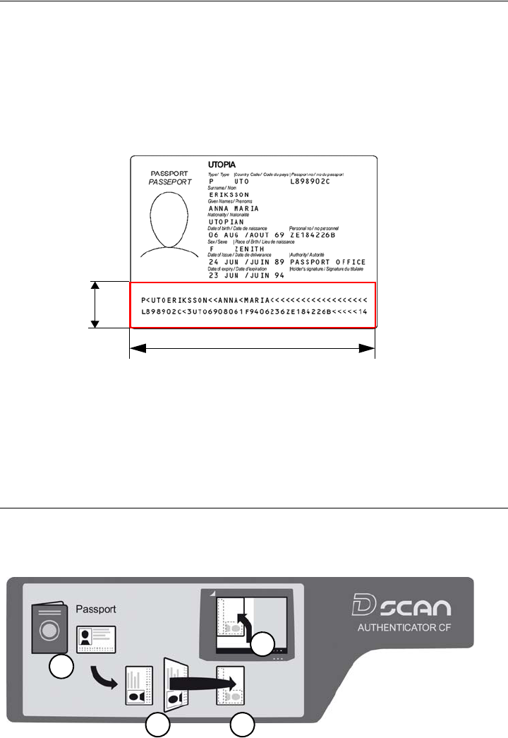
The machine readable zone
ICAO Doc 9303 requires that machine-readable data of a document be available
within a specific zone. The MRZ is a defined rectangle situated exactly at the
lower edge of the document:
• 23.2 mm (0.91 in) height from the lower edge of the document
• Over the total width of the document
• It spans two lines and each line is 44 characters long
Figure 4.1
The machine readable zone
The document contact area of the D SCAN AUTHENTICATOR CF goes beyond
the ICAO-MRZ. In customer specific applications, it is also possible to read zones
outside the MRZ of documents which do not meet the requirements of ICAO Doc
9303.as long as the physical conditions (font, size, printing quality, lamination,
etc.) of the document to be inspected allow this.
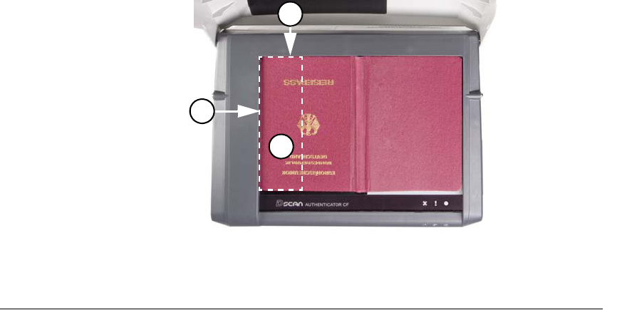
Positioning of documents
An instruction label on the cover provides schematic information for the user to
place a document.
Figure 4.2
Instruction label on the cover
23.2
(0.91)
document
width
1
2 3
4
4-4 D SCAN® AUTHENTICATOR CF™ User Manual V2.0
How to use the Authenticator CF
The procedure requires usually four steps:
1Find the data page.
2Rotate this page in such a manner that it faces down and the MRZ (M) is
pointing left.
3Put the page face down on the document contact area.
4Move the document along the left part of the positioning angle until it stops.
• The accurate final position must be along the left (L) and the back (B) part of
the document positioning angle.
Figure 4.3
Positioning of a passport
Read in a document
The following section describes a complete document reading process using the
D SCAN Master Demo application as an example and explains how to use the
system correctly. The operation and display of results is controlled by the software
as well as all functions.
Depending on your used software and your station policy, the computer screens
may differ from this example. Also the status lights can be used in different
methods. However the operation of the D SCAN AUTHENTICATOR CF will
always be the same.
Note
Before a document is processed ensure that the document contact area is clean. Remove
smudges, laminate glue, finger prints or other dirt that may blur the document being
processed. Avoid touching the document glass with fingers prior put on a document.
The D SCAN AUTHENTICATOR CF is very easy to use and to handle:
1Power on the D SCAN AUTHENTICATOR CF.
2Ensure that the ambient light cover is in the operating position.
3Switch on your computer.
4Start the D SCAN Master Demo application. The software initializes the D
SCAN AUTHENTICATOR CF and switches it to the operation mode.
L
B
M
Read in a document 4-5
How to use the Authenticator CF
• Depending on the performance of your computer, starting up can take a short
moment.
• After successfully initialization the Overview window appears.
Warning
Do not look directly into the lights of the document contact area. Maintain a required
minimum distance of not less than 11.8 inches (0.3 m).
5Put the data page of the document to be read face down on the document
contact area so that the MRZ is pointing left.
6A short acoustic signal indicates that the document is in the correct position.
The processing starts automatically and the processing light is yellow.
Note
Don't move the document until the yellow processing light turns off.
7Now you can remove the document. The yellow processing light indicates that
an image was recorded and is being processed.
• When the D SCAN AUTHENTICATOR CF has completed processing the
document, the processing light turns off, the green operation light comes on
and a short acoustic signal occurs.
8All data submitted to the computer are displayed on the computer screen.
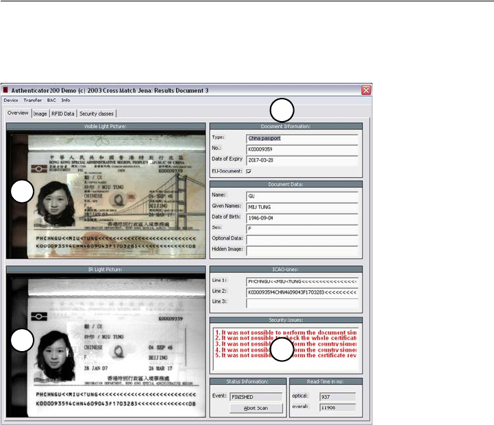
The Overview page
•The Overview page is the default page to show the data of the processed
document. Use the tabs at the top to navigate and to view all data and
images.
Figure 4.4
Overview page
1
2
3
4
4-6 D SCAN® AUTHENTICATOR CF™ User Manual V2.0
How to use the Authenticator CF
• The left side shows both captured images. At the top the image taken with
visible light (1) and below with infrared light (2).
• The right side shows the captured visible data (3), which are printed on the
document.
• Additionally security information, error messages and processing
information (4) are shown at the lower part on the right side. Errors or failed
verifications are shown in red.
•The Abort Scan button allows the operator to interrupt the scanning process.
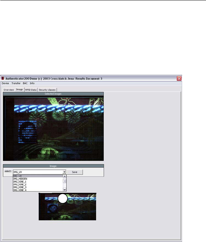
The Images page
1The tab Images provides the ability to show all available images in full screen
resolution captured under different illuminations depending on the features
installed in the D SCAN AUTHENTICATOR CF.
• Click the down arrow in the Select box to see a list (5) containing all
possible images. Chose the desired image from the list using the mouse.
The D SCAN AUTHENTICATOR CF does not support all image types of
this list. To check which image types will be supported start the D SCAN
TestWizard and refer to the Image Acquisition page.
• Clicking the button Save, stores the chosen image on your local disk.
Figure 4.5
Image page
5
Read in a document 4-7
How to use the Authenticator CF
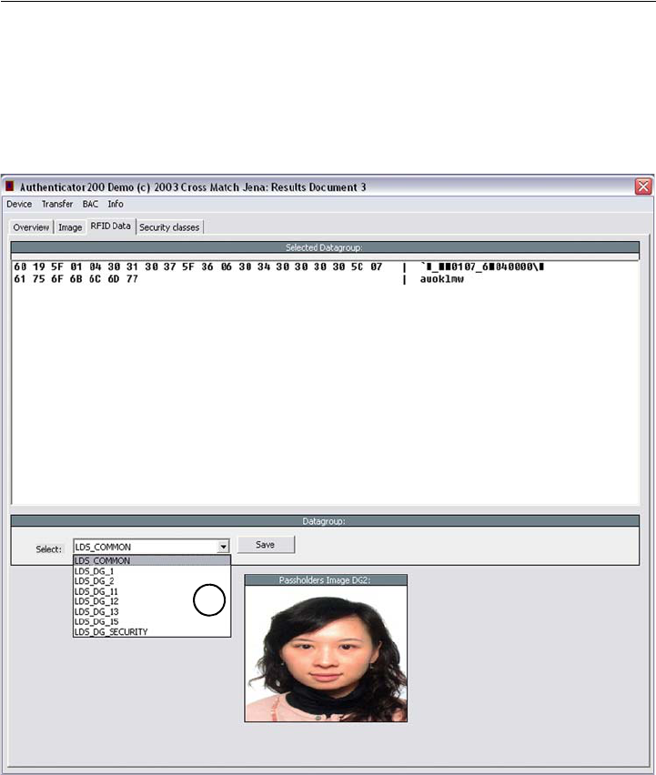
The RFID data page
1Using the tab RFID Data provides the ability to show all data groups in the
Hex-Format found on the RFID chip.
• Click the down arrow in the Select box to see a list (6) containing all data
groups. Chose the desired data group from the list using the mouse. If no
RFID data available the Select box is grayed out.
• Clicking the button Save, stores the chosen data group on your local disk.
Figure 4.6
RFID data page
In the event of mistakes during the processing, or if the processed document is not
recognized, the field Security Issues of the Overview page shows the message
unknown document type.
Repeat the operation with the same document to ensure that the problem was not
caused by mispositioning the document. Correct the position by lifting-up and
then repositioning the document.
The D SCAN AUTHENTICATOR CF is ready to process the next document.
6
4-8 D SCAN® AUTHENTICATOR CF™ User Manual V2.0
How to use the Authenticator CF
Cleaning 5-1
5
Chapter 0Maintenance
T
HIS
CHAPTER
DESCRIBES
MAINTENANCE
PROCEDURES
THAT
INCREASE
THE
LIFE
OF
THE
DOCUMENT
READER
.
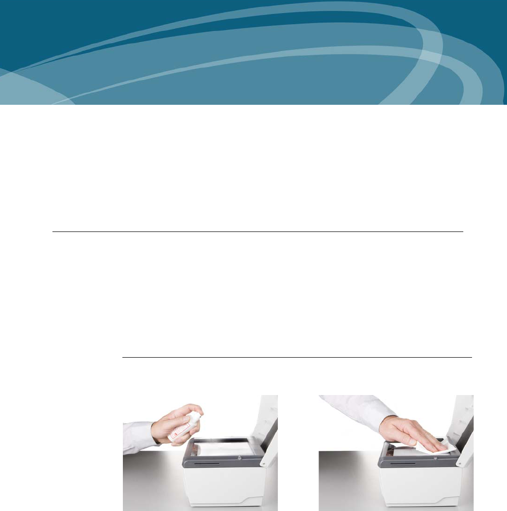
Cleaning
This section shows and describes how to clean the document contact area and the
case. A clean document contact area is required for proper operation. It prevents
dirt from reducing the image quality of the processed document.Clean the platen
with normal glass cleaner and make sure that no dirt, fluids or skin oils remain.
Warning
Do not pour liquids (water etc.) onto the document reader. The document reader device is
protected against cleaning with a damp cloth or tissue, however it is not waterproof.
Caution
Do not use oil-based cleaners or abrasive cleaners.
Cleaning the document contact area
1Spray the glass cleaner sparingly onto the document contact area.
Figure 5.1
Clean the document contact area
2With a lint-free cloth or tissue, wipe off the document contact area until clean
and dry.
3Ensure that the document contact area is dry before starting the reading
process.

5-2 D SCAN® AUTHENTICATOR CF™ User Manual V2.0
Maintenance
Cleaning the case
Warning
Before you clean the case, disconnect the D SCAN AUTHENTICATOR CF from the
grounded outlet.
To remove smudges, laminate glue, finger prints or other dirt, and grime:
1Take a soft, lint free cloth and put a small amount of glass cleaner on it.
2Carefully wipe the case in a direction AWAY from the document contact area.
Caution
Do not use acetone, oil-based, abrasive or other unauthorized cleaners. This may damage
the device and render it inoperable. Using unapproved cleaning solutions will void the
warranty.
Specifications
Table 5.2
Product specifications
Item Specification
Resolution Native 475 ppi sensor for best recognition of high
density features
Dynamic range White light and UV24 bit RGB color, IR light: 8 bit
gray scale
Illumination Standard: white light, IR light and coaxial light (not
available in all markets)
Optional: UV
Document support field size 5.9” x 7.4” (151 x 189 mm), document thickness is
not limited
Optical scan format Active size 5.3” x 3.9” (135 x 100 mm)
Optical scanning time approx. 2 seconds for all images combined
Supported documents Compliant with ICAO 9303 documents of ID1,
ID2, and ID3 format, other ID-1, ID-2 and ID-3
documents on request
Document thickness Not limited
RFID chip access According to ISO 14443 Type-A and Type-B plus
applicable ICAO recommendations in ICAO Doc
9303 including supplement, LDS 1.7,PKI 1.1
RFID speed All standardized rates, up to 848 Kbps, read-out
times depend on RFID tag, operating system, and
amount of data stored in the chip
Smart card reader Contact SmartCard reader with landing contacts
and able to read cards according to ISO 7816
protocol Type T=0 (asynchronous half duplex
character transmission protocol) and T=1
(asynchronous half duplex block transmission
protocol).
Environmental conditions Indoor use, climate classification according to DIN
EN 60 721-3-3
Temperature range 50°F to 113°F (+10°C to +45°C)

Specifications 5-3
Maintenance
Humidity range 10 - 90% relative humidity, non condensing, no
direct sunlight exposure
Dimensions
(W x D x H) 10.36” x 8.35” x 5.89”
(263 x 212 x 150 mm)
Weight approximately 6.6 lbs (3 kg), excluding cables
and power pack
Interface USB 2.0 High Speed, shielded cable
Power supply Rated input: 21 ±3 V DC / min. 1 A and max. 7 A,
Current used: Desktop power pack 19 V DC /
< 30W, wide-range, input AC 100-240 V, 50/60
Hz
Regulatory FCC, CE
Table 5.2
Product specifications
Item Specification
5-4 D SCAN® AUTHENTICATOR CF™ User Manual V2.0
Maintenance

6-1
6
Chapter 0Problems and
Corrections
T
HIS
CHAPTER
CONTAINS
COMMON
PROBLEMS
AND
STEPS
TO
CORRECT
THEM
.
Do the procedures in this section before you contact the Cross Match Technical
Support department.
The Authenticator does not work
The error messages displayed:
None. However the yellow processing light is flashing.
First actions to correct the problem
1 Test the electrical outlet to ensure that the electrical outlet is working.
2 Check the correct installation of the power supply.
3 Verify USB cable is firmly connected to the computer or hub.
More actions to correct the problem
1 Check the correct installation of the hardware driver.
2 Replace the USB cable to find out if it is defective.
3 Contact the Technical Support department.
Authenticator disconnected during operation
The error messages displayed:
Connection broken.
The yellow processing light is flashing.
First actions to correct the problem
1 Confirm the message Connection broken by clicking OK.
2 Re-establish the USB connection.
3 Re-connect the power to the Authenticator.

6-2 D SCAN® AUTHENTICATOR CF™ User Manual V2.0
Problems and Corrections
4 Initialize the Authenticator again.
More actions to correct the problem
Contact the Technical Support department.
Initialization failed
The error messages displayed:
None. However the yellow processing light is on.
First actions to correct the problem
1 Verify USB cable is firmly connected to the computer or hub.
2 Initialize the Authenticator again.
More actions to correct the problem
1 Open the Windows Task Manager and close the AU_HAL Server.exe.
2 Initialize the Authenticator again.
3 Contact the Technical Support department.
Dark image sections
The error messages displayed:
None
First actions to correct the problem
1 Clean the processing surface.
2 Ensure that you have no direct light exposure shining onto the processing
surface.
3 Verify the correct installation of all software and hardware components.
More actions to correct the problem
Contact the Technical Support department.
Visualization and processing speed too slow
The error messages displayed:
None
First actions to correct the problem
1 Verify the system requirements. See, “System requirements” on page 2-6.
2 Verify that you do not use a USB 1.1 interface port.
More actions to correct the problem
Contact the Technical Support department.

6-3
Problems and Corrections
Creating a problem report
If the steps mentioned before were unsuccessful, please use the D SCAN
TestWizard to perform a complete interactive diagnostic of the system.
1 Start the D SCAN TestWizard.
2 Perform a complete system test.
3 Create a log file.
4 Save the log file.
5 Send the log file to the responsible Service Center.
6-4 D SCAN® AUTHENTICATOR CF™ User Manual V2.0
Problems and Corrections

Technical Support 7-1
7
Chapter 0Customer Care and
Contact Information
THIS CHAPTER CONTAINS TECHNICAL SUPPORT INFORMATION FOR THE PRODUCT
AND CONTACT INFORMATION FOR THE COMPANY.
Technical Support
The Technical Support department is available for the D SCAN
AUTHENTICATOR CF.
E-mail
Cross Match Customer Care offers free technical hardware support on-line during
the warranty period, in the order that the requests are received.
If the warranty has expired, contact Technical Support by telephone or facsimile.
Telephone and facsimile
Customer Care is available at the following telephone numbers:
Table 7.1
The Technical Support department addresses
North America and South America Europe, Africa, Asia and Australia
CustomerCare@crossmatch.com Support.cmj@crossmatch.com
Table 7.2
The Technical Support department numbers
North America and South America Europe, Africa, Asia and Australia
Monday- Friday 8 am to 5:30 pm EST Monday- Friday 8 am to 4 pm CET
Customer Care
Tel: 1.866.276.7761 (Toll Free)
Tel: 1.561.622.9210 (International)
Fax: 1.561.622.8769
Manager, Customer Service
Tel: +49 (0)3641 4297-57
Fax: +49 (0)3641 4297-757
7-2 D SCAN® AUTHENTICATOR CF™ User Manual V2.0
Customer Care and Contact Information
Free technical support is available by telephone or facsimile for the D SCAN
AUTHENTICATOR CF under the warranty. After the warranty has expired,
technical support is available at a given cost per hour. Contact Technical Support
for complete information.
The Technical Support for the software products and the services purchased from
Cross Match Technologies is not included under the warranty. The Technical
Support for other products is available at a given cost to the customer. Support for
software development related questions is, up to a certain limit, usually included
in every SDK purchase.
When you contact Technical Support, make sure that you can provide the
following information:
• Company name
• Contact person
• The D SCAN AUTHENTICATOR CF serial number (found on the back of
product)
• The configuration of your PC workstation or laptop
• The error messages that appear on the screen
• The log file created by the D SCAN TestWizard, the test images and the
background images
Return and repair of the Authenticator CF
You must have an RMA number to return a D SCAN AUTHENTICATOR CF for
repair or replacement. Contact the Technical Support department to request and
receive an RMA number. Put the RMA number on the outside of the box and on
the label.
The product is sent to the correct department for service or replacement, then
returned to the customer. Any product sent to Cross Match Technologies without
an RMA number is returned.
Delivery costs
The product is in the warranty period
• The customer accepts all charges to send the product to Cross Match for
service.
Table 7.3
The addresses for product returns
North America and South America Europe, Africa, Asia and Australia
Cross Match Technologies, Inc.
3960 RCA Boulevard, Suite 6001
Palm Beach Gardens, Florida
33410
USA
RMA: Rnnnn.nnnn
Cross Match Technologies GmbH
Service Department
Unstrutweg 4
07743 Jena
Germany
RMA NNNN

Contact information 7-3
Customer Care and Contact Information
• Cross Match accepts all charges to return the product to the customer.
The product is not in the warranty period
The customer accepts all charges.
Note
You must return a product in the original boxes. If the original boxes are not available,
contact the Technical Support department for instructions.
Contact information
Corporate Headquarters
Cross Match Technologies, Inc.
3950 RCA Boulevard, Suite 5001
Palm Beach Gardens, FL 33410
USA
T: +1 (561) 622-1650
F: +1 (561) 622-9938
T: (866) 725-3926 (Toll Free)
General Mailbox: info@crossmatch.com
Sales Department: sales@crossmatch.com
Technical Support: CustomerCare@crossmatch.com
IGerman Operations
Cross Match Technologies GmbH
Unstrutweg 4
07743 Jena
Germany
T: +49 (0)3641 4297-0
F: +49 (0)3641 4297-14
Sales Department: international-sales@crossmatch.com
(Sales EMEA, Asia & Pacific)
Technical Support: Support.cmj@crossmatch.com
Corporate Web Page
www.crossmatch.com
7-4 D SCAN® AUTHENTICATOR CF™ User Manual V2.0
Customer Care and Contact Information

Index-1
Index
A
appropriate operation 1-1
Authenticator CF
before using 2-7
packing list 2-7
unpacking 2-7
Authenticator CF major components 2-3
B
barcode 1-4
before using the Authenticator CF 2-7
C
clean the processing surface 5-1
cleaning 5-1
common problems 7-1
company
telephone number 7-3
connect the Authenticator CF 2-7
connecting cables 2-7
contact information 7-3
corporate headquarters 7-3
Germany 7-3
corporate headquarters 7-3
corporate web page 7-3
D
D SCAN Master Demo software
Images 4-6
Overview 4-5
RFID Data 4-7
E
e-mail, see contact information
F
FCC statement 1-2
freight guidelines 7-2
not under warranty 7-3
under warranty 7-2
G
Germany 7-3
glass cleaner 5-1
glossary 1-4
H
help 7-1
technical 7-1
how this book is organized 1-1
I
ICAO Doc 9303 1-5
Industry Canada 1-2
installation 1-1, 2-1, 2-7, 4-1
M
machine-readable data 4-3
mistakes 4-7
MRZ 1-6
N
not under warranty 7-3
P
packing list 2-7
power supply 5-3
prepare to use the Authenticator CF 2-7
problems 7-1
R
read in 4-4
recycling information 1-3
repeat the operation 4-7
resolution 5-2
returns and repair 7-2
RFID 5-2
RMA number 7-2
S
safety 1-3
specifications
dimensions 5-3
humidity range 5-3
illumination 5-2
interface 5-3
regulatory 5-3
resolution 5-2
temperature range 5-2
weight 5-3
standards
caution 1-2
danger 1-2
note 1-2
warning 1-2
Statement of Compliance 1-3
system requirements 2-6
hardware 2-6
operating system 2-6
T
technical help 7-1
technical support 7-1
e-mail
returns and repair 7-2