CyberTAN Technology RV215W Wireless-N VPN Firewall User Manual RV215W quick 1
CyberTAN Technology Inc. Wireless-N VPN Firewall RV215W quick 1
Contents
- 1. User Manual 1
- 2. User Manual 2
User Manual 1
Quick Start Guide
Cisco Small Business
RV215W Wireless-N VPN Firewall
Package Contents
•Wireless-N VPN Firewall
•Ethernet Cable
•Power Adapter
•Quick Start Guide
•Documentation and software on CD-ROM
Welcome
Thank you for choosing the Cisco Small Business RV215W Wireless-N VPN
Firewall.
The RV215W provides simple, affordable, secure business-class connectivity
to the Internet for small office/home office (SoHo) and remote professionals.
This guide describes how to physically install your Cisco RV215W and launch
the web-based Device Manager to configure and manage your firewall.
Installing the RV215W
Placement Tips
•Ambient Temperature—To prevent the firewall from overheating, do not
operate it in an area that exceeds an ambient temperature of 104°F (40°C).
•Air Flow—Be sure that there is adequate air flow around the firewall.
•Mechanical Loading—Be sure that the firewall is level and stable to avoid
any hazardous conditions.
Place the Cisco RV215W unit horizontally on a flat surface so that it sits on its
four rubber feet.
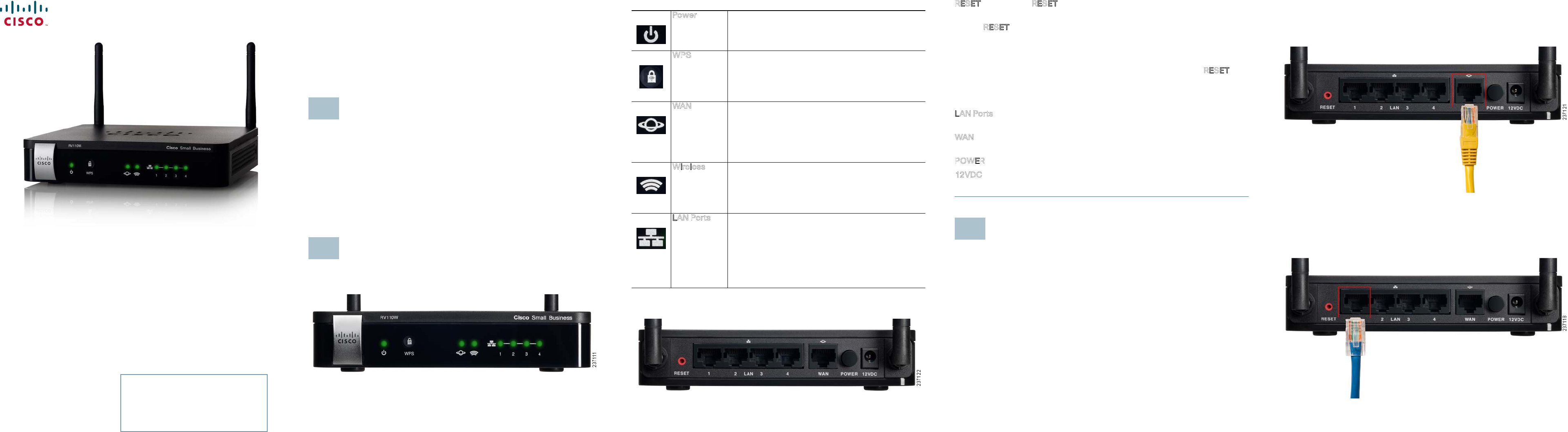
Cisco RV215W Features
Front Panel
1
2
Back Panel
Power The Power light is green to indicate the unit is
powered on. The light flashes green when the
power is coming on.
WPS The Wi-Fi Protected Setup (WPS) button is used to
configure wireless access for devices in your
network that are WPS-enabled. See the
Administration Guide
or Device Manager help page
for more information.
WAN The WAN (Internet) light is green when the Cisco
RV215W is connected to the Internet through your
cable or DSL modem. The light is off when the
Cisco RV215W is not connected to the Internet.
The light flashes green when it is sending or
receiving data
Wireless The Wireless light is green when the wireless
module is enabled. The light is off when the
wireless module is disabled. The light flashes
green when the firewall is transmitting or receiving
data on the wireless module.
LAN Ports The numbered lights correspond to the LAN ports
on the Cisco RV215W.
If the lights are continuously lit green, the Cisco
RV215W is connected to a device through the
corresponding port (1, 2, 3, or 4). The light for a port
flashes green when the firewall is actively sending
or receiving data over that port.
RESET Button—The RESET button has two functions:
•If the Cisco RV215W is having problems connecting to the Internet, press
the RESET button for at least 3 but no more than 10 seconds with a paper
clip or a pencil tip. This is similar to pressing the reset button on your PC to
reboot it.
•If you are experiencing extreme problems with the Cisco RV215W and have
tried all other troubleshooting measures, press and hold in the RESET
button for more than 10 seconds. This reboots the unit and restores the
factory defaults. Changes you have made to the Cisco RV215W settings are
lost.
LAN Ports (1-4)—These ports provide a LAN connection to network devices,
such as PCs, print servers, or switches.
WAN (Internet) Port—The WAN port is connected to your Internet device, such
as a cable or DSL modem.
POWER Button—Press this button to turn the firewall on and off.
12VDC Port—The 12VDC port is where you connect the provided 12 volt DC
power adapter.
Connecting the Equipment
NOTE You must connect one PC with an Ethernet cable for the purpose of the
initial configuration. After you complete the initial configuration,
administrative tasks can be performed using a wireless connection.
STEP 1Power off all equipment, including the cable or DSL modem, the PC you
will use to connect to the Cisco RV215W, and the Cisco RV215W.
3
STEP 2You should already have an Ethernet cable connecting your PC to your
current cable or DSL modem. Unplug one end of the cable from your
PC and plug it into the port marked “WAN” on the unit.
STEP 3Connect one end of a different Ethernet cable to one of the LAN
(Ethernet) ports on the back of the unit. (In this example, the LAN 1 port
is used.) Connect the other end to an Ethernet port on the PC that you
will use to run the web-based Setup Wizard and Device Manager.
STEP 4Power on the cable or DSL modem and wait until the connection is
active.
Versión en Español para España en el CD
Version en français sur CD
Versione italiana sul CD
Deutsch Version auf CD
Versão em português em CD
Americas Headquarters
Cisco Systems, Inc.
170 West Tasman Drive
San Jose, CA 95134-1706
USA
www.cisco.com
Small Business Support US: 1-866-606-1866 (Toll Free, 24/7)
Small Business Support, Global: www.cisco.com/go/sbsc
Cisco and the Cisco Logo are trademarks of Cisco Systems, Inc. and/or its affiliates in the U.S. and
other countries. A listing of Cisco's trademarks can be found at www.cisco.com/go/trademarks.
Third party trademarks mentioned are the property of their respective owners. The use of the word
partner does not imply a partnership relationship between Cisco and any other company. (1005R)
© 2011 Cisco Systems, Inc. All rights reserved.
78-19329-01
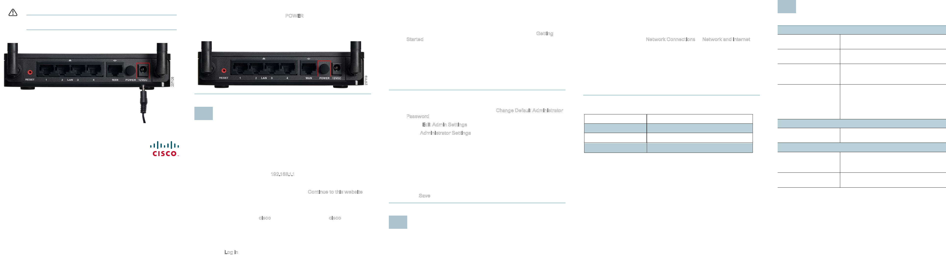
STEP 5Connect the power adapter to the Cisco RV215W POWER port.
CAUTION Use only the power adapter that is supplied with the unit. Using
a different power adapter could damage the unit.
STEP 6Plug the other end of the adapter into an electrical outlet. You may
need to use a specific plug (supplied) for your country.
STEP 7On the Cisco RV215W, push the POWER button in to turn on the
firewall. The power light on the front panel is green when the power
adapter is connected properly and the unit is turned on.
Using the Setup Wizard
NOTE The Setup Wizard and Device Manager are supported on Microsoft
Internet Explorer 6.0 or later, Mozilla Firefox 3.0 or later, and Apple Safari 3.0
or later.
STEP 1Power on the PC that you connected to the LAN1 port in Step 2 of the
Connecting the Equipment section. Your PC becomes a DHCP client
of the firewall and receives an IP address in the 192.168.1.xxx range.
STEP 2Start a web browser on your PC. In the Address bar, enter the default
IP address of the firewall: 192.168.1.1. A message appears about the
site’s security certificate. The Cisco RV215W uses a self-signed
security certificate and this message appears because the firewall is
not known to your PC. You can safely click Continue to this website (or
the option shown on your particular web browser) to go to the web
site.
STEP 3When the login page appears, enter the user name and password. The
default user name is cisco. The default password is cisco. Passwords
are case sensitive.
NOTE For security reasons, change the default user name and password as
soon as possible. See the Changing the Administrator User Name and
Password section.
STEP 4Click Log In.
4
STEP 5The Setup Wizard automatically starts. Follow the on-screen
instructions to set up your firewall. The Setup Wizard tries to
automatically detect and configure your connection. If it is unable to do
so, it may ask you for some information about your Internet connection.
You may need to contact your ISP to obtain this information.
STEP 6After the Setup Wizard completes your configuration, the Getting
Started page of the Device Manager appears. The Getting Started
page displays some of the most common configuration tasks, including
configuring LAN, WAN, and wireless settings, upgrading firmware,
adding users, and configuring the Virtual Private Network (VPN). Click
the listed tasks to view the corresponding configuration windows.
To view other configuration tasks, click a menu item on the left panel to
expand it. Click the menu names displayed underneath to perform an
action or view a sub-menu.
Changing the Administrator User Name and Password
STEP 1From the Getting Started page, choose Change Default Administrator
Password.
STEP 2Select Edit Admin Settings.
STEP 3In the Administrator Settings section, enter the new administrator
username. We recommend that you do not use “cisco.”
STEP 4Enter the old password.
STEP 5Enter the new password. Passwords should not contain dictionary
words from any language or the default password, and they should
contain a mix of letters (both upper- and lowercase), numbers, and
symbols. Passwords must be at least 8 but no more than 30
characters.
STEP 6Enter the new password again to confirm.
STEP 7Click Save.
Connecting to Your Wireless Network
To connect a device (such as a PC) to your wireless network, you must
configure the wireless connection on the device with the wireless security
information you configured using the Device Manager.
5
The following steps are provided as an example; you may need to configure
your device differently. For instructions that are specific to your device, consult
the user documentation for your device.
STEP 1Open the wireless connection settings window or program for your
device. Your PC may have special software installed to manage
wireless connections, or you may find wireless connections under the
Control Panel in the Network Connections or Network and Internet
window. (The location depends on your operating system.)
STEP 2Enter the network name (SSID) you chose for your network when you
configured the Cisco RV215W.
STEP 3Choose the type of encryption and enter the security key that you
chose when setting up the Cisco RV215W. If you did not enable
security (not recommended), leave these fields blank.
STEP 4Verify your wireless connection and save your settings.
Where to Go From Here
Support
Cisco Small Business
Support Community
www.cisco.com/go/smallbizsupport
Cisco Small Business
Support and Resources
www.cisco.com/go/smallbizhelp
Phone Support Contacts www.cisco.com/en/US/support/
tsd_cisco_small_business
_support_center_contacts.html
Cisco Small Business
Firmware Downloads
www.cisco.com/cisco/software/
navigator.html?i=!ch
Select a link to download firmware for Cisco
Small Business Products. No login is
required.
Product Documentation
Cisco Small Business
Routers and Firewalls
www.cisco.com/go/smallbizrouters
Cisco Small Business
Cisco Partner Central
for Small Business
(Partner Login Required)
www.cisco.com/web/partners/sell/smb
Cisco Small Business
Home
www.cisco.com/smb
6
System Specification
Model Name
RV215W Wireless-N VPN Firewall
Operating Frequency 2.4 GHz
Input Power 12V DC/1A
RF Output Power 18 dBm