DAIN TELECOM MYNET-8104 Internet Gateway Router User Manual Mynet 8104 Cable DSL Router Install Guide
DAIN TELECOM CO., LTD. Internet Gateway Router Mynet 8104 Cable DSL Router Install Guide
users manual

FCC NOTICE
THIS DEVICE COMPLIES WITH PART 15 OF THE FCC RULES.
OPERATION IS SUBJECT TO THE FOLLOWING TWO CONDITION:
(1) THIS DEVICE MAY NOT CAUSE HARMFUL INTERFERENCE, AND
(2) THIS DEVICE MUST ACCEPT ANY INTERFERENCE RECEIVED,
INCLUDING INTERFERENCE THAT MAY CAUSE UNDERSIRED
OPERATION.
This equipment has been tested and found to comply with the limits for a Class
B digital device, pursuant to part 15 of the FCC Rules. These limits are
designed to provide reasonable protection against harmful interference in a
residential installation. This equipment generates, uses and can radiate radio
frequency energy and, if not installed and used in accordance with the
instructions, may cause harmful interference to radio
communication. However, there is no guarantee that interference will not occur
in a particular installation. If this equipment does cause harmful interference to
radio or television reception, which can be determined by turning the equipment
off and on, the user is encouraged to try to correct the interference by one or
more of the following measures :
- Reorient or relocate the receiving antenna.
- Increase the separation between the equipment and receiver.
- Connect the equipment into an outlet on a circuit difference from that to which
the receiver is connected.
- Consult the dealer of an experienced radio/TV technician for help.
NOTE : The manufacturer is not responsible for any radio or TV
interference caused by unauthorized modifications to this
equipment. Such modifications could void the user’s
authority to operate the equipment.
contents
- MyNet-810x Introduction
Introduction
Specification of product
Package content
- MyNet-810x Hardware Installation
Hardware Installation
Connect MyNet-810x to ADSL/Cable Modem
Connect the computer to MyNet-810x
Connecting the power
- PC Configuration
PC Network Installation
- MyNet-810x Configuration
Menu items
MyNet-810x environment establishing
Basic Setup Menu description
DHCP Menu explanation
Special Setup Menu explanation
Password Menu explanation
Access Control Menu explanation
Virtual Server Menu explanation
Static Routing Menu explanation
DMZ Host Menu explanation
Upgrade Menu explanation
1. MyNet-810x Introduction
MyNet-series Broadband Internet Gateways are designed for small business and
home (SOHO). Each of MyNet gateways provides the easiest and safest way to share
your broadband Internet access such as DSL modem or cable modem. MyNet-series
are an integrated high speed Internet gateway and firewall with dual speed switch of a
1 & 4 port 10/100M auto-sense for users to immediately network and access the
Internet economically and effortlessly. All users can have Internet access
simultaneously via single IP of Cable/xDSL account. Designed for workgroups of up
to 253 users, the MyNet-810x can be seamlessly configured through a user-friendly
interface. The above product has the built-in DHCP Client and PPPoE client to work
together with Cable Modem and xDSL, and contains the DHCP server for the
automatic Local network. For the various application of equipment, WAN (Internet)
port’s IP information can be composed manually. By realizing the high speed NAT
using the high functioned CPU and optimized software, the delay of data transmission
was minimized when the Cable/xDSL modem are connected and used.
This product will act as firewall for your PCs, protecting you from intruders. In
enhanced by including the various built-in firewall rule, which is optimized. Also, it
has the function of limiting the internet use. This product has the flexible virtual server
function which can designate the port range and has the built-in DMZ Host function.
The user is possible to implement the software upgrade with only FTP client without
the individual software tool in the Local web. This product supports to DNS Proxy and
when the user connects internet by the name cache, the connecting time is made to
be diminished. Also supports the function of VPN client Path-Thru and the PPTP
client and IPSEC client can be used.
.
◈ Specification of product
Protocols TCP/IP, DHCP, DNS, NAT, FTP, HTTP, PPPoE
VPN Pass-Thru (PPPT, IPSec) Yes
Number of LAN connections 253
Internet access controls (filtering) IP filtering
Web-based configuration Yes
Network Address Translation (NAT) Yes
DHCP Server Yes
DNS Proxy Yes
External MDI/MDX switch Yes
Virtual Server support Yes
Static IP address assignment Yes
Dynamic IP address assignment Yes
Software Upgrade Yes
Interfaces
InterfacesInterfaces
Interfaces
WAN Port 10Base-T 1 x RJ45
LAN Port 10/100Mbps 1 x RJ45 (MyNet-8101)
4 x RJ45 (MyNet-8104)
Up-link port
Physical
Physical Physical
Physical
Dimension 145mm x 35mm x 173.5mm
Operating temperature 0 ~ 70°C
Operating humidity 5% ~ 90%
Power Adapter
Power AdapterPower Adapter
Power Adapter
Input : AC100V~AC230V
Output : DC7.5V, 750mA
◈ Composition of product package
; One MyNet-8101 or MyNet-8104 unit
; One Power adapter
; One LAN cable
; One Installation guide

Chapter 2. Hardware Installation
◈ Hardware installation
You must check the internet is possible to use prior to connection of MyNet-8101 &
MyNet-8104 into LAN. In case that the internet does not work, you can ask your internet
service provider the internet shall be working normally.
◈ Connect MyNet-810x to ADSL/Cable Modem
Once you are sure that the internet is working normally. If it is verified to work normally,
install it according to the following procedure.
1) Turn off the PC.
2) Turn off the power of ADSL/Cable Modem.
3) Move and insert LAN cable from PC LAN connected with ADSL/Cable Modem into the
WAN Port of MyNet-8101, MyNet-8104. (Again certify that WAN Port of ADSL/Cable
Modem and MyNet-8101,MyNet-8104 is connected to the LAN cable.)
◈ Connect the computer to MyNet-8101, MyNet-8104
1) Use the hub to connect the computer to MyNet-8101
If the hub is used, you can use the internet upto the maximum 253 numbers of computers.
If you connect the hub to MyNet-8101, connect the LAN cable provided with the product
to the UPLINK port and the hub’s port of MyNet-8101.
By using the LAN cable, connect the LAN card and hub of PC.
2) Connect the computer to MyNet-8104
MyNet-8104 has the high-performance switch with the built-in, 4 numbers of computer to
the maximum without the additional equipment can be connected. By connecting the
maximum 253 numbers of computers in connecting with hub, you can use the internet.
You can connect to the LAN card of computer and LAN 1~4 port of MyNet-8104. (It is
possible to connect directly up to maximum 4 numbers.)
If you want to connect more than 4 numbers of computers to the MyNet
If you want to connect more than 4 numbers of computers to the MyNetIf you want to connect more than 4 numbers of computers to the MyNet
If you want to connect more than 4 numbers of computers to the MyNet-
--
-8104, you can
8104, you can 8104, you can
8104, you can
use it by connecting the hub to the MyNet
use it by connecting the hub to the MyNetuse it by connecting the hub to the MyNet
use it by connecting the hub to the MyNet-
--
-8104.
8104.8104.
8104.
◈ Connecting the power
1) Connect the adapter provided with the product to the power receptacle.
2) Connect the power plug of adapter to the rear DC IN receptacle.
Chapter 3. PC Network Installation
In the case of Windows 95/98 user, it is assumed that LAN card is installed and worked
normally.
1) Select “my computer” in desktop.
2) Select the “control panel” in my computer’s folder.
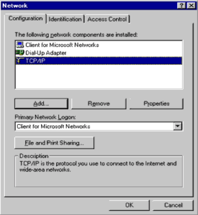
3) Find “network” in control panel and select.
Figure 3-1 control panel network window
4) Find “TCP/IP” item and double click.
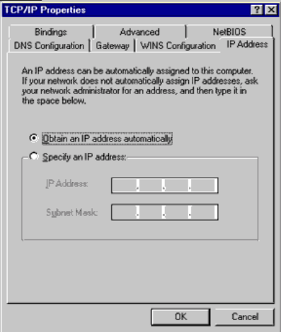
Figure 3-2 TCP/IP registration window
5) Select “IP address” in the item of TCP/IP.
6) Select “Designate IP address automatically” and press the confirmation button.
7) Get out of the control panel and restart the Windows.
* Be ready Windows 95/98 CD.
Chapter 4. MyNet-810x Configuration
* In that this product’s base value is set already in delivery, you can use this product
with only hardware installation.
* This product establishes the environment through the web browser (Netscape
Communicator, Internet Explorer, etc).
◈ Menu items
- Basic setup: Establishing menu of basic environment like LAN Address, WAN Address,
DNS, PPPoE, etc.
- Special Setup: Menu changing MAC Address
- Password: Menu changing the administrator’s password
- Status: Menu displaying the current established contents
- DHCP: Menu establishing whether use of DHCP Server or not and the user numbers of
inside dynamic IP.
- Access Control: Menu controlling the Local network user’s access to internet.
- Virtual Server: Menu establishing the Web server or FTP server to the Local network.
- Static Routing: Menu establishing to communicate between the Local network and to
exchange the routing information between router.
- DMZ Host: Menu establishing whether of using DMZ Host or not and DMZ Host IP
Address.
- Upgrade: Menu downloaded from the site designated the additional function.
◈ MyNet-810x environment establishing
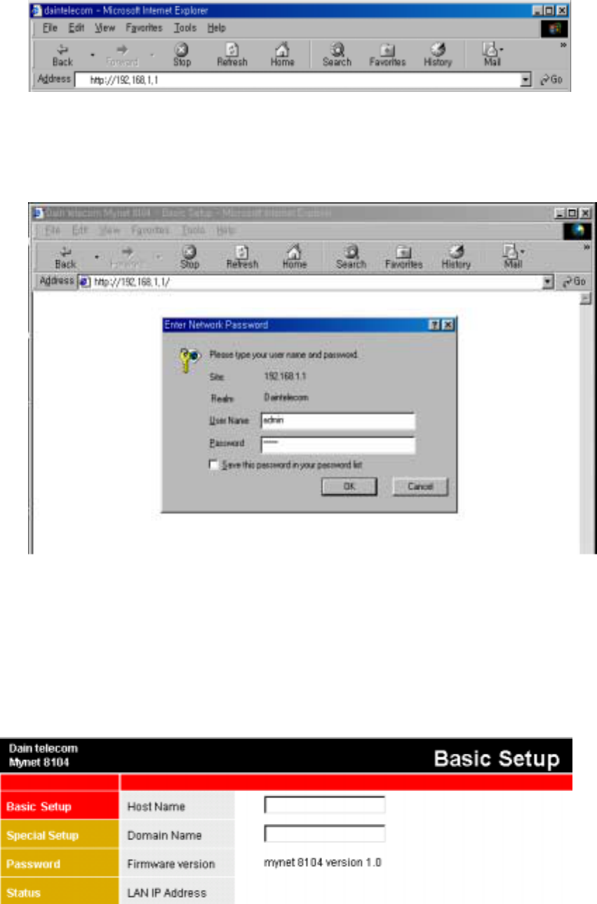
1) Please insert 192.168.1.1 on the web browser’s address in order to establish the
environment of MyNet-810x.
* Address 192.168.1.1 is already established MyNet-810x IP address in delivery
of product.
Figure 4-1 MyNet-810x connection window
2) If the connection is successful, the login dialogue box is shown as figure 4-2.
Figure 4-2 MyNet-810x login window
① Insert admin at the user’s name and password in the dialogue box.
② In product delivery, admin is established as the basic value.
③ The password can be changed at the Password menu.
◈ Basic Setup Menu description

Figure 4-3 Basic Setup window
1) If the login is implemented, Basic Setup (figure 4-3) window is displayed.
2) Explanation of input items
① Host Name: (selection item) In case the specific internet company is asking, it is
usable.
② Domain Name: (selection item) In case the specific internet company is asking, it
is usable.
③ LAN IP Address
- Device IP Address: The part establishing the MyNet-810x IP Address
- In product delivery, it is set to 192.168.1.1
- In case it is to be changed to other value, other value can be inserted
instead of 192.168.1.1
ex) in case of being changed to 192.168.1.2
- Subnet Mask: insert the Subnet Mask
- In product delivery, it is set to 255.255.255.0.
④ WAN IP Address (in case of Cable Modem user)
The part establishing the IP Address certified from outside. And there can be two
cases that the dynamic IP is assigned and static IP is assigned.
a) In case that the dynamic IP is assigned from internet company.
Figure 4-4 in case of flow IP being assigned
- As figure 4-4, select the part of Obtain an IP Automatically.
- Press the submit button.
Figure 4-4 in case of static IP being assigned
- As figure 4-4, select the part of Obtain an IP Automatically
- Select “Submit”button
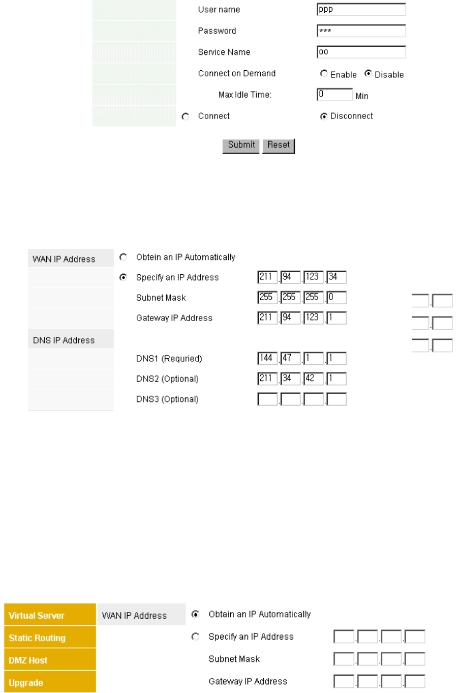
b) In case the static IP is assigned from the internet company.
Figure 4-5 in case of static IP being assigned
- As figure 4-5, select the part of Specify an IP Address.
- In case the static IP is assigned, insert the DNS IP Address.
- The example of above figure 4-5 is that the static IP Address is 211.94.123.34,
Subnet Mask is 255.255.255.0 and Gateway IP Address is 211.94.123.1.
- After inserting the IP Address, Subnet Mask, Gateway IP Address and DNS IP
Address, press the submit button.
⑤ WAN IP Address (in case of ADSL user)
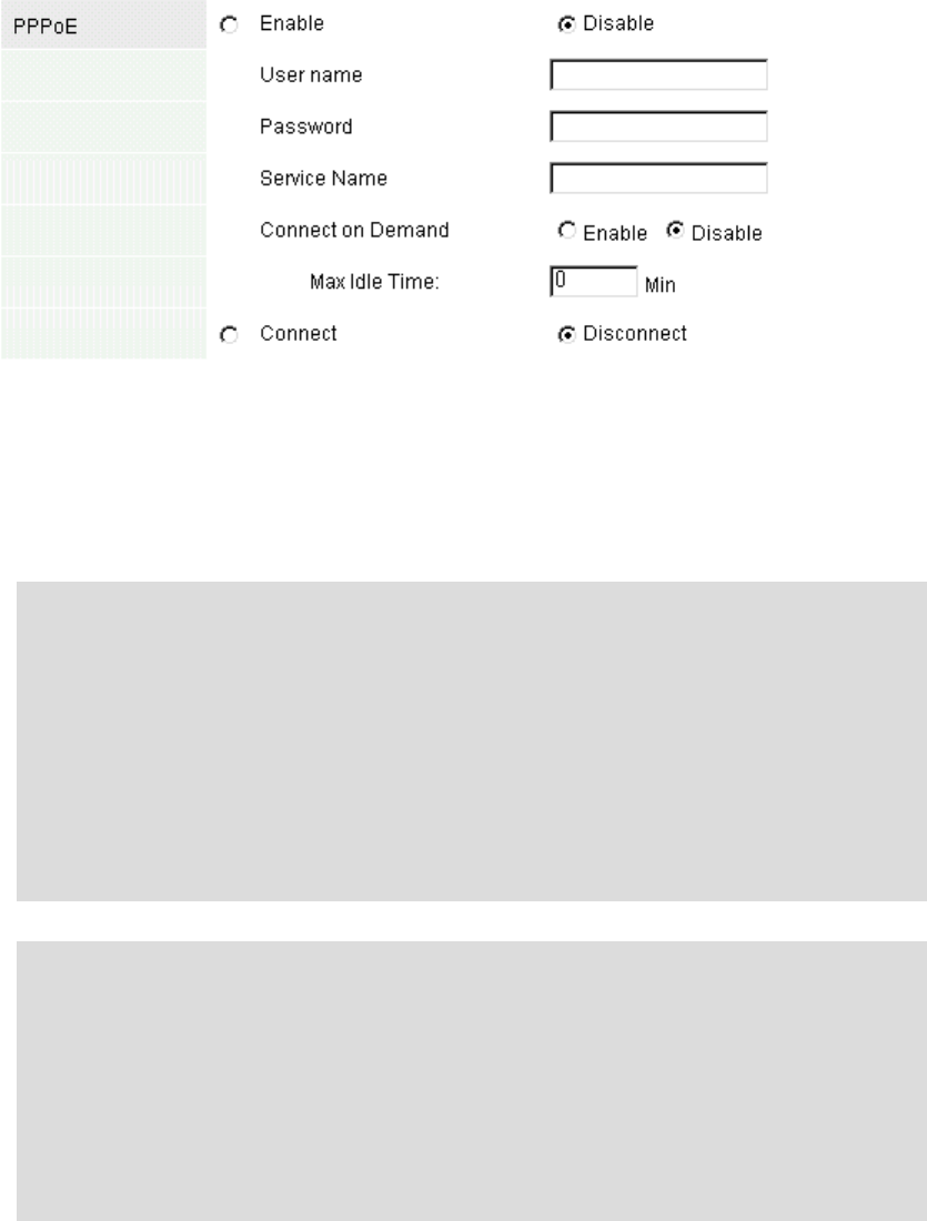
Figure 4-6 PPPoE establishing
- In order to connect to ADSL, select the WAN IP Address as the above figure by
Obtain an IP Automatically and insert User name, Password, Service Name to the
part of PPPoE. Then select Enable and Connect for PPPoE and press the submit
button.
“CONNECT ON DEMAND” is the function that when the user tries to connect the
internet, PPPOE client works and is connected to ADSL network. If this function is
made to do “Enable”, it connects when it does not connect directly to ADSL
network and the user tries to start communication. If it is used like the next menu,
“Max Idle Time” and the user’s communication is halted as much as the set time
at the “Max Idle Time”, it is disconnected and it is changed to stand-by mode.
After this, if the user starts the communication, at this time, it is connected to ADSL
network.
If the internet is not used at the condition of ADSL connection, “Max Idle Time” will
be automatically disconnected. After disconnecting, according to whether of
“CONNECT ON DEMAND” being working or not, if “CONNECT ON DEMAND” is
in the condition of “Enable”, it is changed to stand-by mode and observed by the
user’s observation. If it is the condition of “Disable”, immediately it will be
reconnected. Accordingly, if “CONNECT ON DEMAND” is not used, you had better
not establish the “Max Idle Time” very little.
____________________________________________________________________________________
** According to ISP, the method of connecting and use is different. Therefore, if each
function is not used properly, you can meet with using internet not properly. Accordingly,
if there are some problems in using internet, it is necessary to verify the connected
service type to ISP.
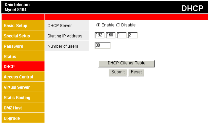
◈ DHCP Menu explanation
Figure 4-7 DHCP Menu window
1) In product delivery, DHCP server is set according to figure 4-7
2) In case DHCP Server is not used
- In the item of DHCP Server, select Disable and press Submit button.
3) In case DHCP Server is used.
① In the item of DHCP Server, select the Enable
② Designate the starting address of IP Address assigned to Local network user
(Figure 4-7 means to allocate the dynamic IP Address from 192.168.1.2.)
③ Finally, it designates the user’s number to be allocated the dynamic IP
(Figure 4-7 means to allocate the dynamic IP Address to Local users, 30 persons)
④ The user numbers that can be allocated the dynamic IP are possible up to
maximum 253 persons
* The remaining menus after this are high-class menus and selected option.
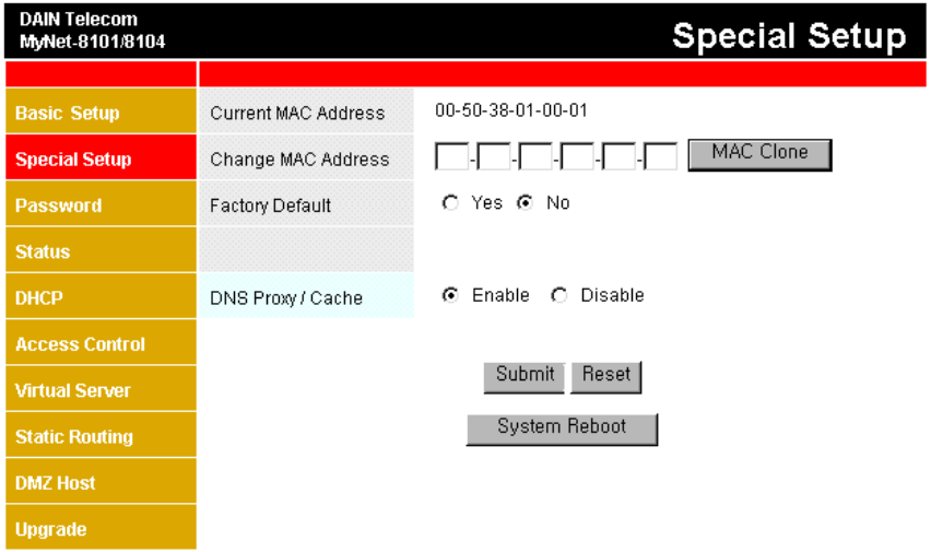
◈ Special Setup Menu explanation
Figure 4-8 Special Setup Menu window
1) In the menu of Special Setup, you can change WAN(Internet) port’s MAC Address.
2) In case of changing MAC Address
- Insert the values to be changed at the part of Change MAC Address and press the
Submit button.
3) If it is changed to established value in product delivery, press “Factory Default”.
4) In case of using DNS Proxy/Cache, select “Enable “button.
(The value in delievery is set up “Enable”already)
5) In case of not using DNS Proxy/Cache, select “Disable”button.
** There is the case that the service is provided to only MAC address of LAN card
which they provided for themselves in terms of ISP partially. In this case, the user shall
verify the MAC address of LAN card provided by ISP and change it. Verification of
MAC address can be implemented by record in LAN card or using the command of
winipcfg(windows 95/98/ME) or ipconfig(windows 2000/NT) in the condition of LAN
card installation.
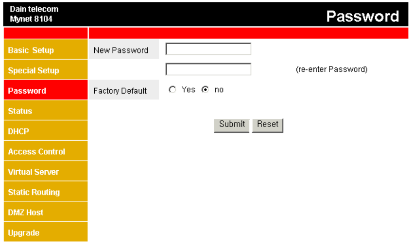
◈Password Menu explanation
Figure 4-9 Password menu window
1) In Password menu, you can change the administrator’s Password.
2) In case of changing the Password
① Insert the password to be changed at New Password.
② Insert the password to be changed once again below the box and press the
Submit button.
3) In case of changing to set value in delivery of product.
- Select “Yes” in the item of Factory Default and press Submit button.
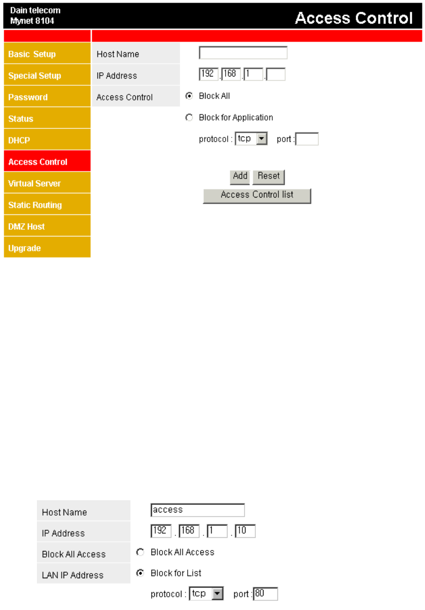
◈ Access Control Menu explanation
Figure 4-10 Access Control Menu window
1) In Access Control menu, outside internet connection of Local network user can be
controlled.
2) Menu item explanation
① Host Name: Insert the Host name of Local network user to be access control.
(optional)
② IP Address: Insert the IP Address of Local network user to be access control.
③ Access Control
- Block All : It stops the access to all outside network service of designated
Local user.
- Block for Application: It stops the access to designated protocol’s port of Local
network user.
Figure 4-11 Access Control example
3) Figure 4-11 is the case that the access of TCP port 80(WEB) by Local user using
192.168.1.10 is prevented.
5) In the above case, the Local user using 192.168.1.10 cannot use the web.
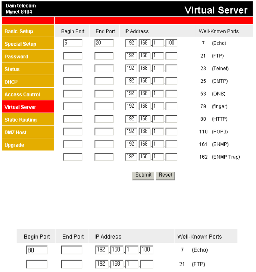
◈ Virtual Server Menu explanation
Figure 4-12 Virtual Server Menu window
1) In Virtual Sever menu, outside access to specific port of Local network can be
designated toward IP Address which is inside designated.
Figure 4-13 Virtual Server example 1
2) The above figure 4-13 means that inside IP Address 192.168.1.100 is activated to
Local web server. In this case, the web server shall be installed at 192.168.1.100.
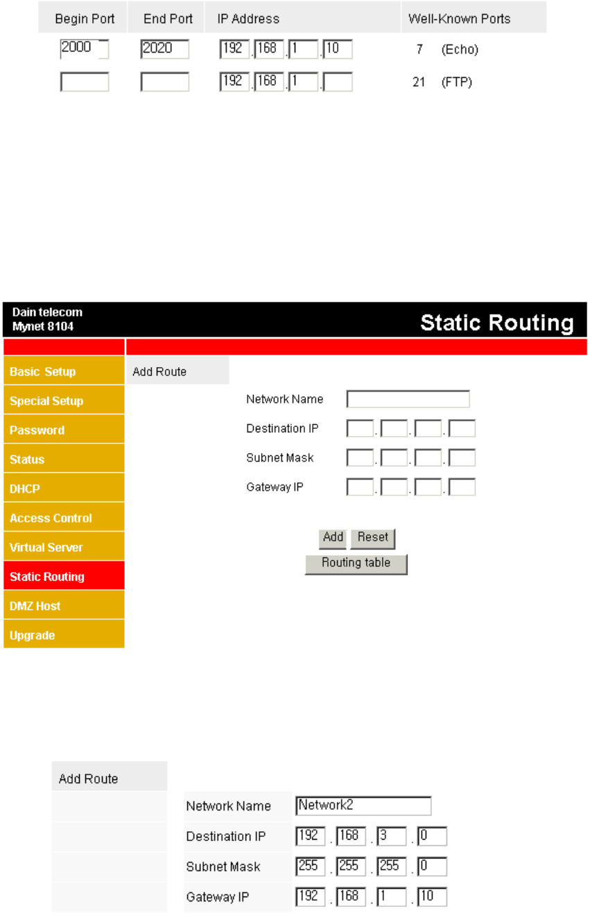
Figure 4-14 Virtual Sever example 2
3) Figure 4-14 means that all outside access from Local network port 2000 to port 2020
shall be toward 192.168.1.10, which is Local network Address.
◈ Static Routing Menu explanation
In case the other network part exists at Local network part, Static Routing menu
functions establishing path to telecommunicate with both different network.
Figure 4-15 Static Routing Menu window
Figure 4-16 Static Routing example 1
- Figure 4-16 is the example to telecommunicate together by the network of 192.168.3.0
doing Gateway to 192.168.1.10.
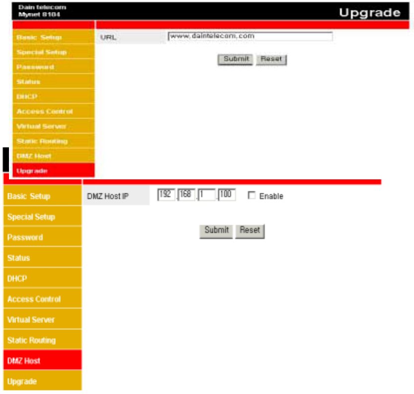
◈ DMZ Host Menu explanation
Figure 4-17 DMZ Host Menu window
1) Inside IP Address to be set as DMZ Host is working such as directly connected to
Cable/DSL.
2) In case of using 192.168.1.100 to DMZ Host, insert 192.168.1.100 to the item of
DMZ Host IP, check Enable and press Submit.
** In case of using DMZ Host and virtual server at the same time, virtual server shall be
applied first due to its priority of established content.
*** As DMZ Host is not exposed to Internet directly, the access from outside is not
protected. Accordingly, it is recommended only special situations such as the case not
sensible to the security, traffic inspection and game, etc.
◈ Upgrade Menu explanation
Figure 4-18 Upgrade Menu window
1) This product’s software is used in upgrade.
2) Once pressing Submit button, the most updated version is downloaded from
designated site, saved automatically at the inside Flash Memory and the equipment
will be restarted.
3) In case automatic upgrade is not wanted from Internet, software to be upgrade is
downloaded to the user, ftp client is used in the Local network and it can be
upgraded as following.
C:>ftp 192.168.1.1
Connected to 192.168.1.1.
220 Simple FTPd welcomes you.
User (192.168.1.1: (none)): admin
331 User name okay, need password.
Password:
230 User logged in proceed.
ftp> put <files name to upgrade>
** Do not disconnect the electric power of the product or pull out the cable of
WAN(Internet) port during upgrade. You may not be able to use the product because the
product’s software is damaged.