Digianswer A S BTDVK100 Bluetooth Developer Kit User Manual dev userguide
Digianswer A/S Bluetooth Developer Kit dev userguide
Contents
- 1. users manual
- 2. usersmanual
users manual

94001480000
Rev. 2.0, 2002-05-29
Bluetooth Development Kit
User’s Guide

Motorola reserves the right to make changes without further notice to any products herein. Motorola makes no warranty,
representation or guarantee regarding the suitability of its products for any particular purpose, nor does Motorola assume any liability
arising out of the application or use of any product or circuit, and specifically disclaims any and all liability, including without limitation
consequential or incidental damages. “Typical” parameters which may be provided in Motorola data sheets and/or specifications can
and do vary in different applications and actual performance may vary over time. All operating parameters, including “Typicals” must
be validated for each customer application by customer’s technical experts. Motorola does not convey any license under its patent
rights nor the rights of others. Motorola products are not designed, intended, or authorized for use as components in systems
intended for surgical implant into the body, or other applications intended to support life, or for any other application in which the
failure of the Motorola product could create a situation where personal injury or death may occur. Should Buyer purchase or use
Motorola products for any such unintended or unauthorized application, Buyer shall indemnify and hold Motorola and its officers,
employees, subsidiaries, affiliates, and distributors harmless against all claims, costs, damages, and expenses, and reasonable
attorney fees arising out of, directly or indirectly, any claim of personal injury or death associated with such unintended or
unauthorized use, even if such claim alleges that Motorola was negligent regarding the design or manufacture of the part. The
Bluetooth trademarks are owned by their proprietor and used by Motorola, Inc., under license. All other product or service names are
the property of their respective owners. © Motorola, Inc. 2002.
Motorola and are registered trademarks of Motorola, Inc. Motorola, Inc. is an Equal Opportunity/Affirmative Action Employer.
How to reach us:
USA/EUROPE/Locations Not Listed: Motorola Literature Distribution; P.O. Box 5405, Denver, Colorado, 80217.
1–303–675–2140 or 1–800–441–2447
JAPAN: Motorola Japan Ltd.; SPS, Technical Information Center, 3–20–1, Minami–Azabu, Minato–ku,
Tokyo 106–8573 Japan. 81–3–3440–3569
ASIA/PACIFIC: Motorola Semiconductors H.K. Ltd., Silicon Harbour Centre, 2 Dai King Street,
Tai Po Industrial Estate, Tai Po, N.T., Hong Kong. 852–26668334
Technical Information Center: 1–800–521–6274
HOME PAGE: http://www.motorola.com/semiconductors/ © Copyright Motorola, Inc., 2002

MOTOROLA Contents iii
Motorola Confidential Proprietary, NDA Required / Preliminary
Chapter 1
Introduction
1.1 About This Guide . . . . . . . . . . . . . . . . . . . . . . . . . . . . . . . . . . . . . . . . . . . . . . . . . . . . . . 1-1
1.2 Additional Documents . . . . . . . . . . . . . . . . . . . . . . . . . . . . . . . . . . . . . . . . . . . . . . . . . . 1-2
1.3 Downloads and Support . . . . . . . . . . . . . . . . . . . . . . . . . . . . . . . . . . . . . . . . . . . . . . . . . 1-3
1.4 Unpacking. . . . . . . . . . . . . . . . . . . . . . . . . . . . . . . . . . . . . . . . . . . . . . . . . . . . . . . . . . . . 1-3
1.5 System Requirements . . . . . . . . . . . . . . . . . . . . . . . . . . . . . . . . . . . . . . . . . . . . . . . . . . . 1-3
1.6 Acronyms and Abbreviations . . . . . . . . . . . . . . . . . . . . . . . . . . . . . . . . . . . . . . . . . . . . . 1-4
Chapter 2
Product Overview
2.1 Block Diagram . . . . . . . . . . . . . . . . . . . . . . . . . . . . . . . . . . . . . . . . . . . . . . . . . . . . . . . . 2-5
2.2 Interfaces. . . . . . . . . . . . . . . . . . . . . . . . . . . . . . . . . . . . . . . . . . . . . . . . . . . . . . . . . . . . . 2-5
2.3 Applications . . . . . . . . . . . . . . . . . . . . . . . . . . . . . . . . . . . . . . . . . . . . . . . . . . . . . . . . . . 2-6
2.4 ICs. . . . . . . . . . . . . . . . . . . . . . . . . . . . . . . . . . . . . . . . . . . . . . . . . . . . . . . . . . . . . . . . . . 2-6
2.5 Software Tools . . . . . . . . . . . . . . . . . . . . . . . . . . . . . . . . . . . . . . . . . . . . . . . . . . . . . . . . 2-6
2.5.1 Bluetooth HCI Terminal . . . . . . . . . . . . . . . . . . . . . . . . . . . . . . . . . . . . . . . . . . . . . . 2-7
2.5.2 Configuration Manager. . . . . . . . . . . . . . . . . . . . . . . . . . . . . . . . . . . . . . . . . . . . . . . 2-7
2.5.3 DemoBench . . . . . . . . . . . . . . . . . . . . . . . . . . . . . . . . . . . . . . . . . . . . . . . . . . . . . . . 2-7
Chapter 3
Setup
3.1 Setting Up Board . . . . . . . . . . . . . . . . . . . . . . . . . . . . . . . . . . . . . . . . . . . . . . . . . . . . . . 3-9
3.2 Running UART. . . . . . . . . . . . . . . . . . . . . . . . . . . . . . . . . . . . . . . . . . . . . . . . . . . . . . . . 3-9
3.3 Running USB . . . . . . . . . . . . . . . . . . . . . . . . . . . . . . . . . . . . . . . . . . . . . . . . . . . . . . . . . 3-9
Chapter 4
Hardware
4.1 Signal and Connection Descriptions. . . . . . . . . . . . . . . . . . . . . . . . . . . . . . . . . . . . . . . 4-11
4.2 Environmental. . . . . . . . . . . . . . . . . . . . . . . . . . . . . . . . . . . . . . . . . . . . . . . . . . . . . . . . 4-12
4.3 Mechanical . . . . . . . . . . . . . . . . . . . . . . . . . . . . . . . . . . . . . . . . . . . . . . . . . . . . . . . . . . 4-12
4.4 Electrical . . . . . . . . . . . . . . . . . . . . . . . . . . . . . . . . . . . . . . . . . . . . . . . . . . . . . . . . . . . . 4-12
4.4.1 Power Supply . . . . . . . . . . . . . . . . . . . . . . . . . . . . . . . . . . . . . . . . . . . . . . . . . . . . . 4-13
4.4.2 Reset Circuit . . . . . . . . . . . . . . . . . . . . . . . . . . . . . . . . . . . . . . . . . . . . . . . . . . . . . . 4-13
4.4.3 Clocks . . . . . . . . . . . . . . . . . . . . . . . . . . . . . . . . . . . . . . . . . . . . . . . . . . . . . . . . . . . 4-13
4.4.4 Memory. . . . . . . . . . . . . . . . . . . . . . . . . . . . . . . . . . . . . . . . . . . . . . . . . . . . . . . . . . 4-14
4.4.5 UART Interface . . . . . . . . . . . . . . . . . . . . . . . . . . . . . . . . . . . . . . . . . . . . . . . . . . . 4-14
4.4.6 USB Interface . . . . . . . . . . . . . . . . . . . . . . . . . . . . . . . . . . . . . . . . . . . . . . . . . . . . . 4-14
Contents

MOTOROLA Contents iv
Motorola Confidential Proprietary, NDA Required / Preliminary
4.4.7 CODEC Interface . . . . . . . . . . . . . . . . . . . . . . . . . . . . . . . . . . . . . . . . . . . . . . . . . . 4-14
4.4.8 Antenna. . . . . . . . . . . . . . . . . . . . . . . . . . . . . . . . . . . . . . . . . . . . . . . . . . . . . . . . . . 4-14
4.5 Reference Designs . . . . . . . . . . . . . . . . . . . . . . . . . . . . . . . . . . . . . . . . . . . . . . . . . . . . 4-14
Chapter 5
Limitations
5.1 USB Limitations . . . . . . . . . . . . . . . . . . . . . . . . . . . . . . . . . . . . . . . . . . . . . . . . . . . . . . 5-15
Chapter 6
Regulatory
6.1 Regulatory Statements . . . . . . . . . . . . . . . . . . . . . . . . . . . . . . . . . . . . . . . . . . . . . . . . . 6-17
6.1.1 General . . . . . . . . . . . . . . . . . . . . . . . . . . . . . . . . . . . . . . . . . . . . . . . . . . . . . . . . . . 6-17
6.1.2 European Union (EU) and EFTA . . . . . . . . . . . . . . . . . . . . . . . . . . . . . . . . . . . . . . 6-17
6.1.3 France . . . . . . . . . . . . . . . . . . . . . . . . . . . . . . . . . . . . . . . . . . . . . . . . . . . . . . . . . . . 6-17
6.1.4 Nederland . . . . . . . . . . . . . . . . . . . . . . . . . . . . . . . . . . . . . . . . . . . . . . . . . . . . . . . . 6-17
6.1.5 United States of America and Canada . . . . . . . . . . . . . . . . . . . . . . . . . . . . . . . . . . 6-18
6.1.6 Canada Compliance (Industry Canada) . . . . . . . . . . . . . . . . . . . . . . . . . . . . . . . . . 6-18
6.1.7 Singapore . . . . . . . . . . . . . . . . . . . . . . . . . . . . . . . . . . . . . . . . . . . . . . . . . . . . . . . . 6-18
6.1.8 Brazil. . . . . . . . . . . . . . . . . . . . . . . . . . . . . . . . . . . . . . . . . . . . . . . . . . . . . . . . . . . . 6-19
6.1.9 Japan . . . . . . . . . . . . . . . . . . . . . . . . . . . . . . . . . . . . . . . . . . . . . . . . . . . . . . . . . . . . 6-19
6.1.10 Taiwan . . . . . . . . . . . . . . . . . . . . . . . . . . . . . . . . . . . . . . . . . . . . . . . . . . . . . . . . . . 6-19
6.2 Obtaining Type Approvals . . . . . . . . . . . . . . . . . . . . . . . . . . . . . . . . . . . . . . . . . . . . . . 6-20
6.2.1 Requirements for Bluetooth Qualification . . . . . . . . . . . . . . . . . . . . . . . . . . . . . . . 6-20
6.2.2 Requirements for regulatory type approvals: . . . . . . . . . . . . . . . . . . . . . . . . . . . . . 6-20
Appendix A
Board Diagram

MOTOROLA Introduction 1-1
Motorola Confidential Proprietary, NDA Required / Preliminary
Chapter 1
Introduction
NOTE:
Users are not permitted to make changes or modify the device in any way.
With the Development Kit for the Bluetooth Platform Solution from Motorola, the company is launching a
unique demonstration and development tool for its platform.
The Development Kit contains all of the hardware, software, and documentation needed to evaluate the
functionality of the ICs making up Motorola’s Bluetooth platform solution chipset:
• MC71000 Bluetooth Baseband Controller IC
• MC13180 Bluetooth Low Power Wireless Data Transceiver IC
• MC13181 Wireless Power Management IC
Also, you can develop software and hardware solutions around the platform chipset. The Development Kit
makes it possible to easily and quickly set up and start demonstrating a Class 2 Bluetooth solution, and it
provides an efficient layout for the baseband and RF on an FR4 PCB substrate.
The primary applications of the Development Kit are:
• Evaluation of the platform chipset and its features
• Porting of a user Bluetooth stack to the Motorola Bluetooth hardware
• Prototyping of a Bluetooth-enabled host device
• Reference design for quick layout of a Bluetooth solution based on the MC71000 and MC13180
chipset
The Development Kit is Bluetooth 1.1 qualified and type approved in a great number of countries. See the
section “Regulatory”.
For detailed information on the ICs making up the platform chipset, please see the technical brief
accompanying each of the ICs: MC71000, MC13180, and MC13181. These technical briefs are all
included on the CD.
1.1 About This Guide
This user’s guide will help you get started with the Bluetooth Development Kit. The guide covers a large
number of aspects of using the Development Kit, including:
• Overview of the Development Kit and accompanying documentation
• Instructions on setting up the hardware and software
• Descriptions of the various elements that make up the Development Kit

1-2 Development Platform Kit User Guide MOTOROLA
Motorola Confidential Proprietary, NDA Required / Preliminary
Introduction
The following is an overview of the various sections of this user’s guide and a brief description of each
section:
•Chapter 1, “Introduction” contains an overview of the user’s guide and additional documents
available from the CD. The introduction is also where to find information on support, unpacking,
system requirements, and a list of the acronyms used in this guide.
•Chapter 2, “Product Overview” provides an overview of the Development Kit where the various
elements of the product are described briefly.
•Chapter 3, “Setup” explains how to set up the hardware and software to get the Development Kit
running.
•Chapter 4, “Hardware” describes the various aspects of the Development Kit hardware
•Chapter 5, “Limitations” describes the limitations of the current Development Kit version.
Currently this chapter deals with HCI Limitations only.
•Chapter 6, “Regulatory” contains regulatory statements, a list of the countries where the
Development Kit will be type approved, and information on what is needed to obtain type approvals
for new products.
•Appendix A, “Board Diagram“, contains a diagram of the Development Kit board.
1.2 Additional Documents
In addition to this user’s guide, the documentation for the Development Kit includes the following
documents. These are all accessible from the document overview on the CD.
• User’s Guides for various elements of the Development Kit:
—Bluetooth HCI Terminal Guide
—Configuration Manager User’s Guide
—DemoBench User’s Guide
— Bluetooth Platform Solution Embedded System User’s Guide
— Bluetooth Headset Guide
• Reference designs: Bluetooth Platform Solution Reference Designs including descriptions and
schematics
• A platform document providing a system overview of the Bluetooth Platform Solution from
Motorola
• Technical briefs for the various Bluetooth platform elements:
— MRFIC2408 External Power Amplifier IC
— MC13180 Bluetooth Low Power Wireless Data Transceiver IC
— MC13181 Wireless Power Management IC
— MC71000 Bluetooth Baseband Controller IC
— Bluetooth Development Kit
• Application notes for the following:
—Using the Bluetooth Audio Signal Processor (BTASP) for High-Quality Audio Performance
— Motorola’s Bluetooth Solution to Interference Rejection and Coexistence with 802.11

Downloads and Support
MOTOROLA Introduction 1-3
Motorola Confidential Proprietary, NDA Required / Preliminary
— Enhancing ISM Band Performance Using Adaptive Frequency Hopping
• Product Errata
• Data sheets and information for components on the Development Kit:
— CODEC
—USB
— UART Level Converter
— EEPROMs
— Crystals
• Bluetooth Core Specification v1.1
1.3 Downloads and Support
For Development Kit software and documentation downloads, go to the following website:
http://www.btpo.net
In addition, you may find useful information on the following websites: http://www.motorola.com and
http://www.motorola.com/semiconductor/bluetooth
For support on your Development Kit, contact your local FAE.
1.4 Unpacking
The Bluetooth Development Kit sales package contains the following items:
• Development kit boards (2)
• Power supplies (2)
• RS232 cables (2)
• USB cables (2)
• Antennas (2)
• Headsets (2)
• Installation CD including software tools and documentation (1)
1.5 System Requirements
To install and use the Bluetooth Development Kit, you will need the following:
• A PC equipped with Windows® 98/98 SE/Me/2000
• At least a 600 MHz processor (or higher)

1-4 Development Platform Kit User Guide MOTOROLA
Motorola Confidential Proprietary, NDA Required / Preliminary
Introduction
1.6 Acronyms and Abbreviations
Throughout this guide, the following acronyms and abbreviations are used:
EEPROM Electrically Erasable/Programmable Read Only Memory
Rx Receive(r)
SEEPROM Serial Electrically Erasable/Programmable Read Only Memory
SPI Serial Peripheral Interface
The SPI Bus made by Motorola handles all serial communication with a number of
different RF front ends and SEEPROMs.
SSI Synchronous Serial Interface
Tx Transmit(ter)
UART Universal Asynchronous Receiver Transmitter

MOTOROLA Product Overview 2-5
Motorola Confidential Proprietary, NDA Required / Preliminary
Chapter 2
Product Overview
This section contains a brief overview of the Development Kit. More detailed information on the various
elements of the Development Kit is included in later sections and in the separate user’s guides included on
the CD.
2.1 Block Diagram
The following figure shows the Development Kit block diagram:
Figure 2-1. Block Diagram
2.2 Interfaces
The development kit features RS232, UART, and USB interfaces:
• RS232 interface: Programmable baud rate from 1200 to 921 Kbit.
• UART interface: 5-pin header with RxD, CTS, RTS, and GND, 3.3 V signaling, programmable
baud rate from 1200 to 921 Kbit, HCI UART transport layer.
USB
RS232
DC
Power
Input
UART
USB
RS232
Level
Shifter
CODEC
Modular Jack
MC71000 MC13180
MC13181 7 Status
LEDs Reset Switch Class ½
Antenna Jumper
EEPROM
Antenna
Diversity
Switch
F Antenna
Antenna
Connector

2-6 Development Platform Kit User Guide MOTOROLA
Motorola Confidential Proprietary, NDA Required / Preliminary
Product Overview
NOTE:
The UART and RS232 interfaces cannot operate simultaneously.
• USB interface: Full speed (12 Mbit/s) USB node device, HCI USB transport layer, 3.3 V operation,
self-powered, National USBN9604 USB controller.
The following list shows the USB limitations:
— USB interface is for evaluation purposes and only included for ease of use.
— Supports OpenUSBDI-compatible USB controllers. USB v1.1.
— Does not support Open HCI.
— Production release of the MC71000 will not support USB.
• Audio connections, with audio routed either to the CODEC or through the transport layer
2.3 Applications
The Development Kit supports the Headset application. A separate Headset User’s Guide is TBD.
2.4 ICs
The Development Kit is supplied with the following Bluetooth ICs from Motorola:
• MC71000 Bluetooth Baseband Controller IC
• MC13180 Bluetooth Low Power Wireless Data Transceiver IC
• MC13181 Wireless Power Management IC
Future Development Kit releases will contain the MRFIC2408 External Power Amplifier IC.
2.5 Software Tools
The Bluetooth Development Kit is accompanied by the following software tools:
• Bluetooth HCI Terminal
• Configuration manager
• DemoBench
The following sections describe briefly each of the software tools. A separate user’s guide for each tool is
included on the Development Kit CD.

Software Tools
MOTOROLA Product Overview 2-7
Motorola Confidential Proprietary, NDA Required / Preliminary
2.5.1 Bluetooth HCI Terminal
With the Bluetooth HCI Terminal you can interact with your Bluetooth hardware. The interface is similar
to that of an AT Terminal application when communicating with a modem. The Bluetooth HCI Terminal
makes it easy to send HCI commands from a computer to a Bluetooth device. Likewise, it is easy to
receive HCI responses from a Bluetooth device. Consequently, you can get hands-on experience with the
HCI. Or you can test your own Bluetooth hardware.
The Bluetooth HCI Terminal is accompanied by the Bluetooth HCI Terminal Guide, accessible from the
document overview on the CD:
2.5.2 Configuration Manager
The Configuration Manager is an application that allows you to handle the Development Kit file system.
With this tool, you can download firmware patches and set up a number of baseband and radio parameters
to exercise the board. All parameters are restorable and default settings are stored automatically.
The Configuration Manager is accompanied by a user’s guide, accessible from the document overview on
the CD.
2.5.3 DemoBench
The DemoBench is a demonstration tool that can be used for a number of purposes. You can send a file to
another Bluetooth device, “chat” with another Bluetooth device, and view link and packet statistics in a
real-time application.
The DemoBench is accompanied by a user’s guide, accessible from the document overview on the CD.

2-8 Development Platform Kit User Guide MOTOROLA
Motorola Confidential Proprietary, NDA Required / Preliminary
Product Overview

MOTOROLA Setup 3-9
Motorola Confidential Proprietary, NDA Required / Preliminary
Chapter 3
Setup
This section provides instructions for setting up the Development Kit hardware and software.
3.1 Setting Up Board
To get the board up and running, do the following:
1. Connect the board and PC via the UART (RS232) cable.
NOTE:
The first time you start up the board, you can only run UART, not USB.
2. Attach power supply to DC connector on board and connect to main electricity supply.
3. Insert the CD in the CD-ROM drive of your PC and follow the onscreen instructions.
3.2 Running UART
To run UART, do the following:
1. Get the board up and running as described above.
2. Download the UART application from the Configuration Manager on the CD.
3.3 Running USB
NOTE:
The first time you start up the board, you can only run UART, not USB.
Follow the above setup instructions.
To run USB, do the following:
1. Make sure the power is turned off the board.
2. Connect the board and PC via the UART (RS232) cable.
3. Attach power supply to DC connector on board and connect to main electricity supply.
4. Download the USB application from the Configuration Manager on the CD.

3-10 Development Platform Kit User Guide MOTOROLA
Motorola Confidential Proprietary, NDA Required / Preliminary
Setup
5. Within the Configuration Manager, go to Settings>Com Port and select the USB option.
6. Follow the instructions on screen to disconnect the UART (RS232) cable and connect the
USB cable.

MOTOROLA Hardware 4-11
Motorola Confidential Proprietary, NDA Required / Preliminary
Chapter 4
Hardware
This section provides information on various aspects of the Development Kit hardware. In addition,
Appendix A, “Board Diagram“, contains a diagram of the Development Kit board.
4.1 Signal and Connection Descriptions
The development kit contains the following connections, switches, and indicators:
• Power supply input
• Modular jack 4/4 connector for mono-audio speaker and microphone (headset application)
• RS232 interface
• UART interface
• USB interface
• Antenna connector
• JTAG allowing interface to MC71000 production test
• Reset switch
• Four control buttons for the headset application
• On/off switch
• Seven status LEDs
The power supplied for the development kit is DC with the ratings stated in the specifications.
An analog audio signal to be transmitted over the Bluetooth connection can be fed into the development kit
via the modular jack or as streaming audio through the host interface. It will be converted to digital data and
transmitted through the Bluetooth link. A digital audio signal received from a connected Bluetooth device
will be converted to an analog audio signal and available at the modular jack or as streaming audio through
the host interface (UART, SSI, SPI). The MC71000 has a Bluetooth Audio Signal Processor (BTASP) for
superior audio performance.
The RS232/UART interfaces can be used to transfer data and audio between a host and the Bluetooth device.
The firmware of the development kit can be upgraded through the RS232/UART interface.
The USB interface is a standard HCI USB interface. This interface can be used to connect the development
kit to a PC or other devices with PC-compatible USB connections.
The CODEC is attached to the MC71000 via the SPI (data) and SSI (streaming audio) interfaces.
The antenna connector is an SMA 50 ohm connection.

4-12 Development Platform Kit User Guide MOTOROLA
Motorola Confidential Proprietary, NDA Required / Preliminary
Hardware
The reset switch can be activated to re-initialize the entire system.
Four buttons are provided for embedded applications:
• Volume up
• Volume down
• Function 1 (connection etc.)
• Function 2 (this is an extra button)
Seven status LEDs are provided:
• Two application-specific LEDs
• Class 2
• 24 MHz/32 kHz
•RX/TX
•Power on
• Diversity (shows which antenna is being used)
4.2 Environmental
This section contains system level environmental information:
• Storage temperature (degrees centigrade):
—Min. -40
—Max +125
• Operating temperature (degrees centigrade):
—Min. -20
—Max +85
4.3 Mechanical
This section contains system level mechanical information:
• Length: 100 mm
• Width: 100 mm
• Height (PCB with components): 20 mm
• Layout, FR4, 6 layer: 1 mm
4.4 Electrical
This section contains electrical information:
• Input power supply requirements: 3.5-6.5 VDC
Electrical
MOTOROLA Hardware 4-13
Motorola Confidential Proprietary, NDA Required / Preliminary
• Audio input: 65m Vpp
• Audio output: 1.6 Vpp, modular jack 4/4 connector
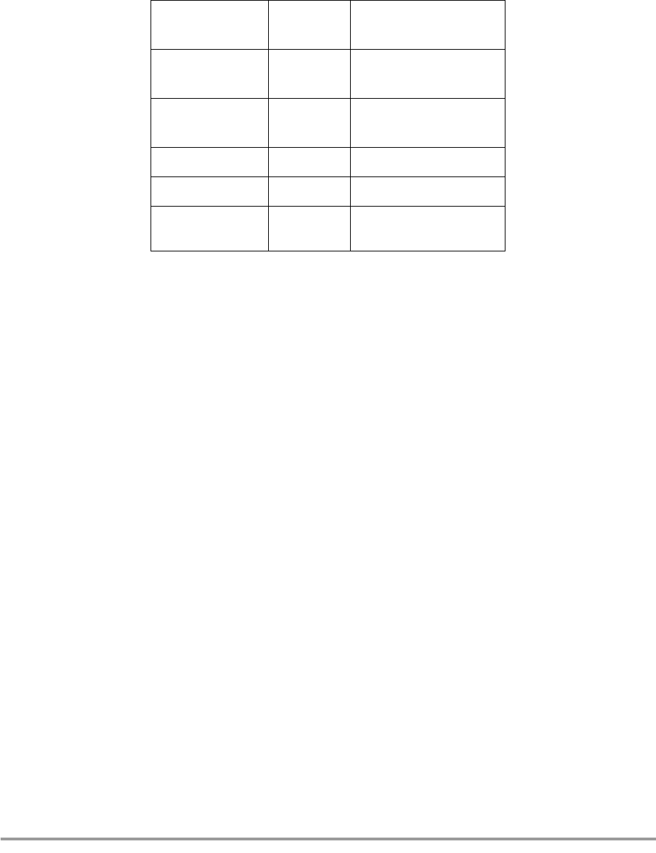
The following table shows the current consumption measurements of the circuits of the MC71000
Bluetooth Baseband Controller and MC13180 Bluetooth Low Power Wireless Data Transceiver ICs.
Note that the table contains typical values.
4.4.1 Power Supply
The board is fed with power from on-board standard regulators.
The on-board power supply regulators should be fed with the supply provided, which generates the
following voltages for the board:
•1.85 V
•2.65 V
•3.3V
4.4.2 Reset Circuit
The board includes a push button for full system reset of the MC71000 and all peripherals.
4.4.3 Clocks
The clocks in the system are as follows:
• Sleep mode clock: 32.768 kHz.
• Active mode clock: 24 MHz from MC13180 radio module
The MC71000 includes an internal oscillator circuit for the 32.768 kHz sleep mode clock. Only an external
crystal and a few other components are needed.
Table 1: Current Consumption Measurements of MC71000 and MC13180 Circuits
DH5 asymmetric
RX 50.4 mA TX rate 57.6 kbits
RX rate 723.2 kbits
DH5 asymmetric
TX 48.5 mA TX rate 723.2 kbits
RX rate 57.6 kbits
DH5 symmetric 45.8 mA TX rate 433.9 kbits
RX rate 433.9 kbits
HV1 45.8 mA
HV3 27.8 mA
Total system in
low-power mode 0.130 mA

4-14 Development Platform Kit User Guide MOTOROLA
Motorola Confidential Proprietary, NDA Required / Preliminary
Hardware
4.4.4 Memory
The MC71000 has embedded memory of 256 Kbytes of ROM and 64 K of RAM. An image can be
uploaded from a host system, or a low-cost serial EEPROM (four-wire connection). For more information
on the contents and structure of the MC71000 memory, please refer to the Bluetooth Platform Solution
Embedded System User’s Guide. This is accessible from the document overview on the Development Kit
CD.
4.4.5 UART Interface
The UART interface is embedded in the MC71000. However, an external level converter is needed. For
this purpose, the MAX3237 1.0 Mbit level converter is used. The level converter is connected to the
MC71000 and a female 9-pin D-sub. The connection between the level converter and the MC71000 is
passed through a jumper block in order to aid debugging, and, if ever needed, to use a different type of
level converter.
4.4.6 USB Interface
The USB interface consists of the National USBN9604 USB device controller. A 3.3 V power supply is
used for the USBN 9604.
For information on the USB limitations of the Development Kit, see the section “USB Limitations”
4.4.7 CODEC Interface
The audio interface consists of the Xemics XE3006 CODEC, a 4-pin header and a 4/4p amp connector. As
to the power supply for the CODEC, both 1.8 V and 3.3 V are selectable by a “+” formation jumper.
Sampling rate is configured at 7.8125 kHz.
4.4.8 Antenna
The Development Kit contains an F entenna and an SMA 50 Ohm antenna connector.
4.5 Reference Designs
The Bluetooth Platform Solution reference designs include the following: Host optimized, host
non-optimized, and standalone (headset). Descriptions and schematics are included in the Bluetooth
Platform Solution Reference Designs document. This is accessible from the document overview on the
Development Kit CD.

MOTOROLA Limitations 5-15
Motorola Confidential Proprietary, NDA Required / Preliminary
Chapter 5
Limitations
This section deals with the known limitations of the Bluetooth Development Kit.
5.1 USB Limitations
The Bluetooth Development Kit has the following USB limitations:
• The USB interface is for evaluation purposes only. It is only included for the purpose of showing
full bandwidth.
• Supports OpenUSBDI-compatible USB controllers. USB V1.1.
• Does NOT support Open HCI.
• No USB logo certification.
• MC71000 does NOT support USB. USB controller is external USBN9604 from National.
For general information on USB, please see www.usb.org.

5-16 Development Platform Kit User Guide MOTOROLA
Motorola Confidential Proprietary, NDA Required / Preliminary
Limitations
MOTOROLA Regulatory 6-17
Motorola Confidential Proprietary, NDA Required / Preliminary
Chapter 6
Regulatory
This section contains regulatory statements, a list of the countries where the Development Kit will be type
approved, and information on what is needed by developers to obtain type approvals for their products.
6.1 Regulatory Statements
NOTE:
Users are not permitted to make changes or modify the system in any way.
Changes or modifications not expressly approved by the party responsible
for compliance could void the user’s authority to operate the equipment.
6.1.1 General
This product complies with any mandatory product specification in any country where the product is sold.
6.1.2 European Union (EU) and EFTA
This equipment complies with the R&TTE directive 1999/5/EC and has been provided with the CE mark
accordingly.
6.1.3 France
This equipment may only be used as a Class 2 device, not as a Class 1 device. Note also that only indoor
use is allowed.
6.1.4 Nederland
(Applies to 20dBm products only)
Niet voor gebruik in de buitenlucht.
Deze apparatuur is uitsluitend bedoeld voor gebruik binnenshuis.
This device is intended for evaluation and development purposes by professionals only and is NOT
for re-sale.

6-18 Development Platform Kit User Guide MOTOROLA
Motorola Confidential Proprietary, NDA Required / Preliminary
Regulatory
6.1.5 United States of America and Canada
Tested to comply with FCC Standards FOR HOME OR OFFICE USE. See FCC 47CFR part 15.19(b)(2)
This device complies with part 15 of the FCC rules and with RSS-210 / RSS-139 of the Industry Canada.
Operation is subject to the following two conditions: (1) This device may not cause harmful interference,
and (2) this device must accept any interference received, including interference that may cause undesired
operation. See FCC regulation CFR47 sec. 15.19(3).
This equipment has been tested and found to comply with the limits for a Class B digital device, pursuant
to part 15 of the FCC Rules. These limits are designed to provide reasonable protection against harmful
interference in a residential installation. This equipment generates, uses and can radiate radio frequency
energy and, if not installed and used in accordance with the instructions, may cause harmful interference to
radio communications. However, there is no guarantee that interference will not occur in a particular
installation. If this equipment does cause harmful interference to radio or television reception, which can
be determined by turning the equipment off and on, the user is encouraged to try to correct the interference
by one or more of the following measures:
• Reorient or relocate the receiving antenna
• Increase the separation between the equipment and receiver
• Connect the equipment into an outlet on a circuit different from that to which the receiver is
connected
• Consult the dealer or an experienced radio/TV technician for help
In order to comply with FCC RF Exposure requirements, a minimum separation distance of 20 cm must
always be maintained between the transmitter antenna and all persons during normal operation.
Note that any changes or modifications to this equipment not expressly approved by the manufacturer may
void the FCC authorization to operate this equipment.See FCC regulation CFR47 sec. 15.21.
6.1.6 Canada Compliance (Industry Canada)
To prevent radio interference to the licensed service, this device is intended to be operated indoors and
away from windows to provide maximum shielding. Equipment that is installed outdoors is subject to
licensing.
In French: Pour empêcher un brouillage radioélectrique au service faisant l'objet d'une licence, cet appareil
doit être utilisé à l'interieur et loin des fenêtres afin de founir un écran de blindage maximal. Au cas aù un
installation en plain air, le materiel doit faire l'objet d'une licence.
6.1.7 Singapore
This product complies with the standard Infocomm Development Authority of Singapore (IDA) TS SSS
amended by the Guidance notes on Bluetooth Type Approval Framework and has been approved by the
IDA under the Type Approval Certificate (TAC) number: Motorola TAC number TBD
The supplier of this equipment is responsible that the equipment can be used as described in the
accompanying documentation. Furthermore, the supplier is responsible for providing proper installation
and after-sales maintance of the equipment to meet the user's needs.
Under no circumstances is the IDA liable for the use, installation, or after-sales maintenance of the
equipment.

Regulatory Statements
MOTOROLA Regulatory 6-19
Motorola Confidential Proprietary, NDA Required / Preliminary
6.1.8 Brazil
Este equipamento opera em caráter secundário, isto é, não tem direito a proteção contra interferência
prejudicial, mesmo de estações do mesmo tipo, e não pode causar interferência a sistemas operando em
caráter primário.
6.1.9 Japan
6.1.10 Taiwan
ߎߩᯏེߩ↪ᵄᢙᏪߢߪޔ㔚ሶࡦࠫ╬ߩ↥ᬺ⑼ቇක≮↪ᯏེߩ߶߆Ꮏ႐ߩㅧ
ࠗࡦ╬ߢ↪ߐࠇߡࠆ⒖േኻ⼂↪ߩ᭴ౝή✢ዪ (⸵ࠍⷐߔࠆή✢ዪ) ߮․ቯዊ
㔚ജή✢ዪ (⸵ࠍⷐߒߥή✢ዪ) ߇ㆇ↪ߐࠇߡ߹ߔޕ
1 ߎߩᯏེࠍ↪ߔࠆ೨ߦޔㄭߊߢ⒖േ⼂↪ߩ᭴ౝή✢ዪ߮․ቯዊ㔚ജή✢ዪ߇ㆇ
↪ߐࠇߡߥߎߣࠍ⏕ߒߡߊߛߐޕ
2 ਁ৻ޔߎߩᯏེ߆ࠄ⒖േ⼂↪ߩ᭴ౝή✢ዪߦኻߒߡ㔚ᵄᐓᷤߩ߇⊒↢ߒߚ႐ว
ߦߪޔㅦ߿߆ߦ↪ᵄᢙࠍᄌᦝߔࠆ߆ߪ㔚ᵄߩ⊒ࠍᱛߒߚޔਅ⸥ㅪ⛊వߦߏㅪ
⛊㗂߈ޔᷙା࿁ㆱߩߚߩಣ⟎╬ (߃߫ޔࡄ࠹࡚ࠖࠪࡦߩ⸳⟎ߥߤ) ߦߟߡߏ⋧⺣ߒ
ߡߊߛߐޕ
3 ߘߩઁޔߎߩᯏེ߆ࠄ⒖േ⼂↪ߩ․ቯዊ㔚ജή✢ዪߦኻߒߡ㔚ᵄᐓᷤߩ߇⊒↢
ߒߚ႐วߥߤ߆߅࿎ࠅߩߎߣ߇߈ߚߣ߈ߪޔᰴߩㅪ⛊వ߳߅วࠊߖਅߐޕ
ㅪ⛊వ㧦03-3440-3311 (+81-33440-3311)
6-20 Development Platform Kit User Guide MOTOROLA
Motorola Confidential Proprietary, NDA Required / Preliminary
Regulatory
6.2 Obtaining Type Approvals
Customers of Motorola Bluetooth chipsets will face some Bluetooth qualification and regulatory
requirements for their products. The following lists the requirements for the major markets as defined by
Digianswer/Motorola as tier 1 countries: Australia, Canada, Europe (15 + 4 EFTA countries), Japan, New
Zealand and US. A number of other countries worldwide will accept the test reports made for Europe
and/or US approvals.
Motorola chipsets (radio/baseband) are pre-qualified as Bluetooth components. Also any variants of
Motorola software stacks will be pre-qualified. The assumption of pre-qualification provides that
customers will implement the radio module (radio chip including surrounding components and print
layout) without any changes.
6.2.1 Requirements for Bluetooth Qualification
Baseband chipset will be used as a pre-qualified component and do not require re-testing.
Any incorporated variant of Motorola software stack will be used as a pre-qualified component and do not
require re-testing.
Radio will need to be re-tested in the product layout for the following 8 (of 16) test cases:
If changes are made to the Development Kit radio module BOM or layout, all 16 Bluetooth test cases will
be required to be re-tested. Depending on the nature of changes to the radio, re-testing might only be
necessary in normal temperature. This has to be decided by the BQB in each case.
6.2.2 Requirements for regulatory type approvals:
The following regulatory testing needs to be made:
• For CE-marking: EN 300 328-2 (emission), EN 301 489-17 (EMC), EN 60950 (safety)
• For Japan approval: ARIB T-66.
• For FCC grant: CFR47 part 15.205, 15.209 and 15.247 (except 15.247e: processing gain)
NOTE:
As Motorola radios will be approved by FCC as radio modules and the
Table 6-1.
TRM/CA/04/E TX Output Spectrum-Frequency range
TRM/CA/08/E Initial Carrier Frequency Tolerance
TRM/CA/09/E Carrier Frequency Drift
TTRC/CA/01/E Out-of-Band Spurious Emissions-radiated
RCV/CA/02/E Sensitivity-multi-slot packets
RCV/CA/03/E C/I performance
RCV/CA/04E Blocking performance
TP/PHYS/TRX/BV-05-C Symbol rate

Obtaining Type Approvals
MOTOROLA Regulatory 6-21
Motorola Confidential Proprietary, NDA Required / Preliminary
FCC testing can be avoided for regulatory purposes for radio modules,
provided no changes are made to the radio module BOM or layout, it will
still be necessary to perform the Out-of-Band Spurious
Emissions-radiated-test of part 15.209.
The product might be subject to additional product specific regulations, such as PSTN regulations and
other.
Type approval applications have to be filed to the national authorities for each product.
Documentation submitted for type approvals can vary from country to country, but will in general include:
test reports, pictures, BOM, schematics, PCB layouts, product descriptions (block diagrams), antenna
information, SAR statements (see below), label/manual information (legal text) and manufacturer
information.
Both in Europe and US regulators are currently working on new sets of rules for combined radio
equipment as well as rules for SAR. Test requirements for SAR (including combined radio) will most
likely be topical within the next year.

6-22 Development Platform Kit User Guide MOTOROLA
Motorola Confidential Proprietary, NDA Required / Preliminary
Regulatory

MOTOROLA A-1
Motorola Confidential Proprietary, NDA Required / Preliminary
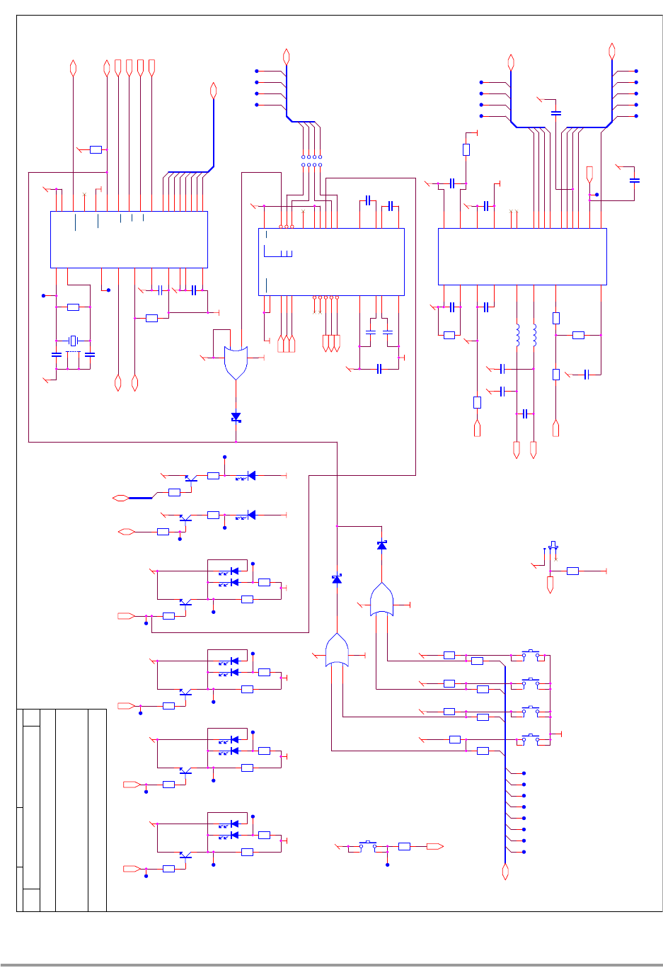
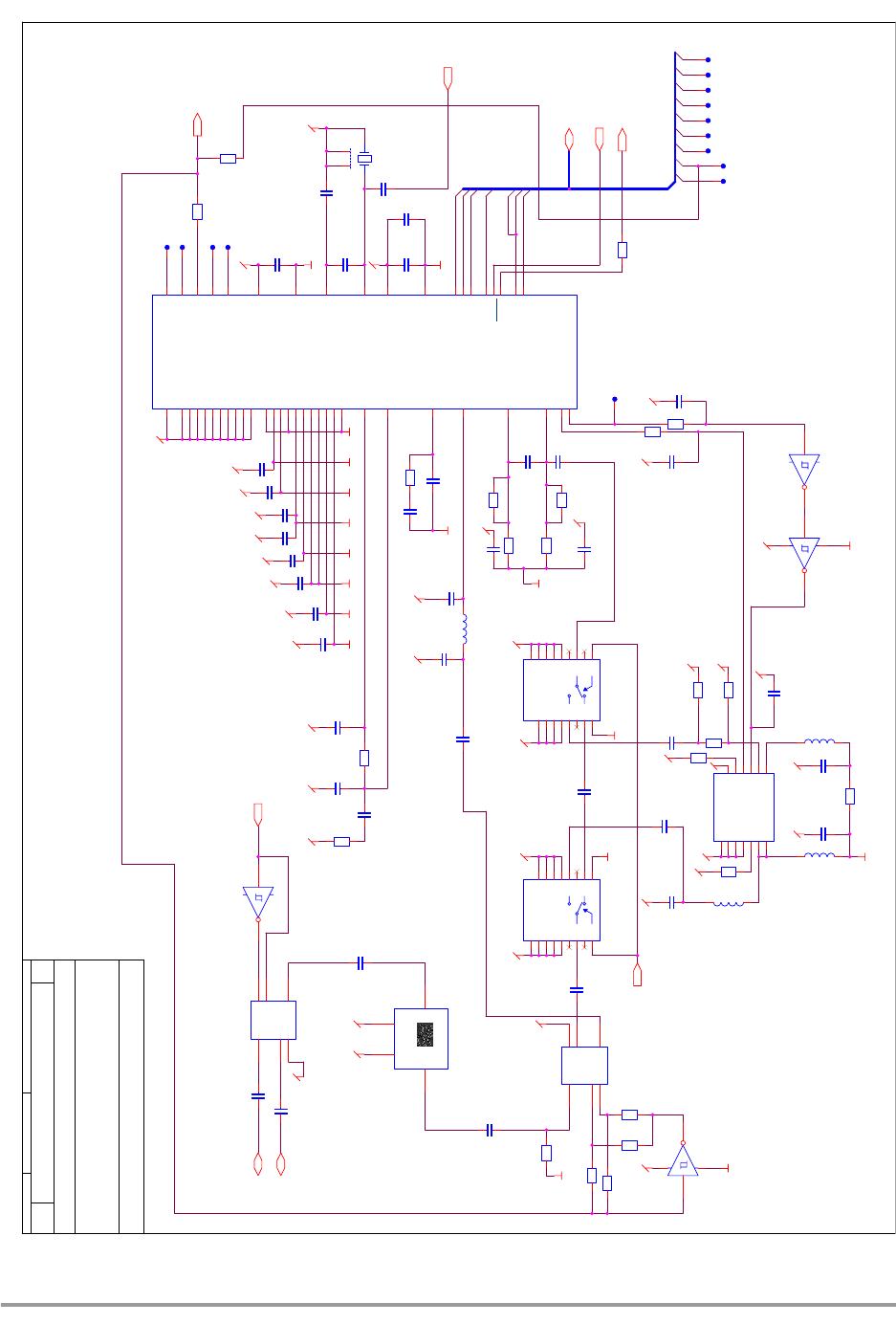
Appendix A
Board Diagram
The following pages show a diagram of the Development Kit board.

A-2 Development Platform Kit User Guide MOTOROLA
Motorola Confidential Proprietary, NDA Required / Preliminary
RTS
TXD
RXD
CTS
RFNET28
RxTx_SW
0dBm/20dBm
MIC-
EAR-
MIC+
EAR+
D[0..7]
GPIO_B11
RTCK
WE
TDI
A0
GPIO_B10
D7
TMS
MAIN-
TRST
TDO
GPIO_C9
SPI0[0..3]
SSI[0..4]
JTAG_RESET
REFCLK
Power ON
BT[1..9]
TCK
UART[0..3]
CS0
CLK0
OE
Reset
REFCTRL
MAIN+
DIVERSITY
RFNET29
VDD_EIM
HVDD1V85HVDD1V85
Title
Size Document Number Rev
Date: Sheet of
C o n f i d e n t i a l I n f o r m a ti o n
This document contains Digianswer A/S confidential and proprietary information, which you are not
entitled to reproduce or disclose to any third party without the prior written consent of Digianswer A/S.
© Digianswer
80000488000_R0404.DSN R04.04
VEGA DK: Polaris peripherals (DIG488-4)
Digianswer A/S
Skalhuse 5
DK-9240 Nibe, Denmark
Telephone: +45 96710000 Fax: +45 98350052 http://www.digianswer.com
A3
15Friday, May 03, 2002 CLL
2001-2002
UART
USB
3.5 - 5.5 VDC
AUDIO
interface
Modular 4/4
Power Supply
Placed i matrix 2x10 @0,1''
ANTENNA
MAIN SYSTEM OSC.
Sleep mode OSC
A101
Primus datum point (Compside)
TP111
TP114
J105
USB Serie-B
VUSB
1
DATA-
2
DATA+
3
GROUND
4
SHIELD1
5
SHIELD2
6
HOLE102
np hole ø2.2mm
CO104
PCB Corner Mark
TP124
TP123
TP120
J100
DC
3
2
1
4
L102
Not Mounted
TP103
IC102
MMQA5V6T1
Not Mounted
C1
6
A1 5
C2
4
C3
3A2 2
C4
1
R109
18R
A102
Secundary fiducial point (Compside)
TP115
R104 0R
R106
10K
HOLE103
np hole ø2.2mm
J109
Not Mounted
1
2
5
3
4
CO102
PCB Corner Mark
J106
4/4p
1
1
2
2
3
3
4
4
TP107
TP112
J103
9p Female Ang
5
9
4
8
3
7
2
6
1
m1 m2
TP121
TP104
C105
22pF
TP106
J108
Not Mounted
1
2
5
3
4
TP116
A103
Secundary fiducial point (Soldside)
Sheet 3
Polaris peripherals
D[0..7]
MIC+
TXD
CTS
RXD
RTS
EAR+
EAR-
GPIO_B11
GPIO_B10
CLK0
UART[0..3]
GPIO_C9
SSI[0..4]
SPI0[0..3] MIC-
Power ON
Reset
A0
CS0
OE
WE
REFCTRL
D-
D+
RxTx_SW
0dBm/20dBm
DIVERSITY
BT[1..9]
BT_WAKEUP
Ri
TP109
HOLE104
np hole ø2.2mm
CO101
PCB Corner Mark
TP113
TP102
Testpoint Coax (Soldside)
TP122
C106
1µF
TP117
C104
22pF
L100
0R
R110
18R
CO103
PCB Corner Mark
R103
0R
Not Mounted
C100
100nF
R100
10K
J107
2p
1 2
TP118
Sheet 4
RF Front
BT[1..9]
Antenna 1
REFCLK
REFCTRL
Antenna 2
DIVERSITY
RxTx_SW
0dBm/20dBm
13MHz_OSC
J102
SMA Receptacle, Female
1
2
5
3
4
BARCODE101
Label 21*6mm Test BarCode
TP110
HOLE101
np hole ø2.2mm
R107
10K
L101
0R
TP105
IC100
MMQA5V6T1
C1 6
A1
5C2 4
C3 3
A2
2
C4 1
R105 0R
Sheet 2
Polaris
TDI
TMS
TCK
TTS
RTCK
BT[1..9]
SSI[0..4]
UART[0..3]
SPI0[0..3]
TRST
GPIO_B11
GPIO_B10
GPIO_C9
REFCTRL
CLK0
D[0..7]
TDO
REFCLK
MAIN-
MAIN+
Power ON
Reset
CS0
OE
WE
A0
DIVERSITY
JTAG_RESET
0dBm/20dBm
32kHz_OSC
TP119
ANT100
F_Antenna
TP108

MOTOROLA A-3
Motorola Confidential Proprietary, NDA Required / Preliminary
D7
CS0
EXTAL
REFCLK
SPI1[0..3]
0dBm/20dBm
BTCLK
WE
GPIO_B10
OE
REFCTRL
SPI10
D[0..7]
SPI11
GPIO_C9
SPI12
CS1
SPI13
S_inv
GPIO_B11
SPI10
RESET
SPI11
SPI12
SPI13
SPI13
SPI12
SPI11
CLK0
SPI0[0..3]
Q2
PWM
SPI10
DIVERSITY
D0
S_inv
BT1
BT2
BT5
BT7
BT9
BT3
BT6
BT8
BT[1..9]
SSI0
D1
SSI2
SSI1
SSI3
SPI03
GPIO_B3
SPI02
SPI00
SSI4
SPI01
SSI[0..4]
D2
D3
BT4
D4
UART0
UART1
UART3
UART2
Q2
UART[0..3]
D5
0dBm/20dBm
D6
XTAL
PWM
A0
SPI0[0..3]
MAIN+
MAIN-
UART[0..3]
GPIO_B11
GPIO_B10
BT[1..9]
SSI[0..4]
D[0..7]
GPIO_C9
TRST
RESET
REFCLK
REFCTRL
CLK0
OE
WE
0dBm/20dBm
Power ON
TDI
TMS
TCK
TTS
TDO
RTCK
CS0
DIVERSITY
JTAG_RESET
32kHz_OSC
BVcc
VCC_RF
VCC
HVDD1V85
HVDD1V85
VCC
HVDD1V85
VccCodec
HVDD3V3
VCC
VCC_PA
VCC
HVDD3V3
HVDD3V3
3V3_USB
HVDD3V3 3V3_UART
VCC_LED
HVDD3V3
HVDD1V85
HVDD3V3
AVcc
HVDD3V3
HVDD1V85 AVcc
HVDD3V3
HVDD3V3
VDD_EIM
Title
Size Document Number Rev
Date: Sheet of
C o n f i d e n t i a l I n f o r m a ti o n
This document contains Digianswer A/S confidential and proprietary information, which you are not
entitled to reproduce or disclose to any third party without the prior written consent of Digianswer A/S.
© Digianswer
80000488000_R0404.DSN R04.04
VEGA DK: Polaris (DIG488-4)
Digianswer A/S
Skalhuse 5
DK-9240 Nibe, Denmark
Telephone: +45 96710000 Fax: +45 98350052 http://www.digianswer.com
A3
25Friday, May 03, 2002 CLL
2001-2002
Battery
Memory
R216
Not Mounted
J200
3p
1
2
3
S201
Switch
1
2
3
C216
10pF
C238
1.0pF
R232
Not Mounted
R206
10K
C217
100nF
C203
100µF
C228
1µF
TP212
R222
0R
C210
1µF
TP206
TP221
TP213
C218
100nF
R236
Not Mounted
TP209
R231
500mA
1 2
R221 0R
C208
100nF
J201
1p
1
1
C235
Not Mounted
TP224
C225
100nF
X200
32.768KHz
R226 0R
IC201
MC71000
TRST_B
K10
TDI
J10
TDO
H9
TMS
H8
TCK
G7
MODE0
G9
MODE1
F6
REFCLK J6
REFCTRL K4
RESETIN_B
F10
CS0_B
A3
Frame synch BT1 K7
RxD BT2 J7
TxD BT3 K8
RxTxEN BT4 J8
SPI clk BT5 K6
SPI_en BT6 K5
SPI do/SPI di BT7 J5
PWM0 / TX_en / GPO0 BT8 H6
PWM1 / PA_en / GPO1 BT9 H7
VDDpa H5
GNDcore_I1_EIM F3
EXTAL J9
XTAL K9
GNDcore_I2_EIM H4
GNDcore_I3 F9
GNDcore_I4_EIM D4
VDDcore_I1_EIM F2
VDDcore_I2_EIM J4
VDDcore_I3_EIM K3
VDDcore_I3 F8
GNDpc C7
VDDpc B7
VDDpb C8
GNDpb D8
SSI_STCK
A9
SSI_STFS
C9
SSI_STD
B9
SSI_SRCK
A10
SSI_SRFS
C10
SSI_SRD
B10
SPI_0_SS_B
B8
SPI_0_SCK
D9
SPI_0_MISO
E8
SPI_0_MOSI
D10
SPI_1_SS_B
D6
SPI_1_SCK
A6
SPI_1_MISO
B6
SPI_1_MOSI
C6
CLK0
E9
TXD
B5
RXD
A7
CTS_B
A5
RTS_B
A8
TTS
G8
CS1_B
C3
A0
B3
A1
E4
A2
A2
A3
D3
A4
F5
A5
B2
A6
A1
A7
B1
A8
C2
A9
C1
A10
D2
A11
D1
D0
F1
D1
G4
D2
G3
D3
G1
D4
G2
D5
H3
D6
H1
D7
H2
RTCK
H10
GNDmisc_I1 G6
VDDmisc_I1 G10
OE_B B4
WE_B A4
GPIO_B10 F7
GPIO_B11 E7
GPIO_B12 E10
CLK1
E5
GPIO_C9 C5
OSC32k D5
SYSCLK E6
BTCLK D7
VDD_I3_EIM K1
VDD_I2_EIM E1
VDDcore_I4_EIM C4
VDD_I4_EIM K2
GNDcore_I3_EIM J3
GND_I4_EIM J2
GND_I3_EIM J1
GND_I2_EIM E2
GND_I7_EIM F4
VDD_I7_EIM E3
GNDpa G5
R233
Not Mounted
R242
7.5R R215 0R
R209
1.5R
C230
100nF
IC205
AT25HP512-10CI-1.8
CS 1
SO 2
WP
3
GND
4SI 5
SCK 6
HOLD
7VCC
8
J202
1p
1
1
X201
Not Mounted
TP218
R219 0R
TP201
R240
10M
R207 1.0K
R2410R
C220
100nF
TP217
C212
10pF
R205
470R
R223
0R
R220 0R
TP222
D203
Green LED
C236
Not Mounted
TP220
IC206A
Not Mounted
1 6
52
TP225
C224
100nF
C207
100nF
C214
3.3µF
TP214
J204
3p
1
2
3
R210
10M
TP215
C239
3.3µF
C229
100nF
C237
1.0pF
TP211
C213
100nF
R229
10K
TP202
R204
1.5R
C234
100nF
C226
100nF
R211
0R
R213
10K
R218
1.0R
R234
Not Mounted
TP204
C205
6.8µF
R217
Not Mounted
TP223
TP226
R230
1.5K
TP219
R203
1.0K
C206
100nF
TP216
C227
100nF
IC206B
Not Mounted
3 4
COT201
Track in PCB
TP200
IC202
MC13181
VCC1
3
Vin+
24
Vin-
23
HysteresisSelect
21
DelayCap 9
Q1_b
10 S INV
6
Q2
11
S OR
12
2V65_ENABLE
17 1V85_ENABLE
18
3V0/3V3 sel
14
3V0/3V3 ENABLE
13
AGND1 4
OUT3V0/3V3 7
OUT2V65 1
OUT1V85 19
RESET_b 15
Detect 22
REFOUT 2
VCC2
8
Shutdown
16
AGND2 20
SGND 5
EP EP
IC203
LP2981IM5-3.3
IN
1OUT 5
ON/OFF
3GND 2
NC 4
TP210
TP207 TP208
TP203
R214
0R
R239 0R
R212
100K
A-4 Development Platform Kit User Guide MOTOROLA
Motorola Confidential Proprietary, NDA Required / Preliminary
UART3
UART2
UART0
UART1
SPI00
SPI01
SPI02
SPI03
SPI00
SPI01
SPI02
SPI03
SSI1
SSI2
SSI3
D0
SSI4
D1 D2
SSI0
D3 D7D6D5D4
BT[1..9]
BT8
SSI4
SSI2
GPIO_B11
D3
CS0
OE
WE
D2D1
D7
D0
A0
UART0
D2
D1
D6
UART1
D4
D0
D3
D[0..7]
D5
UART[0..3]
UART2
GPIO_C9
UART3
SSI[0..4]
SSI3
SSI1
SPI0[0..3]
SSI0
UART[0..3]
SPI0[0..3]
SSI[0..4]
D[0..7]
GPIO_B10
GPIO_C9
D+
D-
D[0..7]
GPIO_B11
MIC-
DIVERSITY
BT[1..9]
MIC+
RESET
A0
OE
WE
EAR+
EAR-
RxTx_SW
CS0
CLK0
0dBm/20dBm
TXD
CTS
RTS
RXD
BT_WAKEUP
Ri
Power ON
REFCTRL
3V3_UART
VccCodec
VCC_LED VCC_LED VCC_LED VCC_LED
BVcc
BVcc
VCC_LED VCC_LED
3V3_USB
3V3_UART
BVcc
3V3_USB
VCC
BVcc
VDD_EIM
Title
Size Document Number Rev
Date: Sheet of
C o n f i d e n t i a l I n f o r m a ti o n
This document contains Digianswer A/S confidential and proprietary information, which you are not
entitled to reproduce or disclose to any third party without the prior written consent of Digianswer A/S.
© Digianswer
80000488000_R0404.DSN R04.04
VEGA DK: Polaris peripherals (DIG488-4)
Digianswer A/S
Skalhuse 5
DK-9240 Nibe, Denmark
Telephone: +45 96710000 Fax: +45 98350052 http://www.digianswer.com
A3
35Friday, May 03, 2002 CLL
2001-2002
SRFS
STCK
SRD
STFS
SYSTEM RESET
SPI_0_SS
SPI_0_SCK
SPI_0_MISO
SPI_0_MOSI
STD
Rx / Tx
RDK specific
24MHz / 32kHz F-antenna /
SMA Connector
Class1 / Class2
Power ON
+/- -/+ FUNC 1 FUNC 2
Codec
USB
Level shifter
Keys
X300
24.000MHz
D300
Green LED
IC301
MAX3237EAI
C1+
28
C1-
25
C2+
1
C2-
3
T1IN
24
T2IN
23
R1OUT
21
R2OUT
20
VCC 26
V+ 27
V- 4
GND 2
T1OUT 5
T2OUT 6
R1IN 8
R2IN 9
T3IN
22
T4IN
19
T5IN
17
T3OUT 7
T4OUT 10
T5OUT 12
R1OUTB
16
R3OUT
18 R3IN 11
MBAUD 15
SHDN 14
EN
13
R328
560K
D306
BAT54
21
TP300
C305
100nF
R308
470R
R307
470R
C321
390pF
TR302B
BC847BS
5
34
TP328
TP333
TP342
R317
10K
R302
0R
TP302
TP322
R321
10K
TP313
R334
470R
R324
10K
G
R
D304
Red/Green LED SMD
1
4 3
2
TR302A
BC847BS
2
61
L301
220µH
R300
2.2K
C325
33pF
C309
100nF
IC307
USBN9604SLB
CS
19
RD
20
WR/SK
21
INTR
22
DRQ
23
DACK
24
A0/ALE/SI
25
D0/S0
26
D1
27
D2
28
D3
1
D4
2
D5
3
D6
4
D7
5
RESET
6
AGND 7
V3.3 8
D+ 9
D- 10
GND1 11
VCC 12
GND 13
MODE1
14 MODE0
15 XIN 16
XOUT 17
CLKOUT 18
C323
33pF
D301
Red LED
C303
100nF
G
R
D303
Red/Green LED SMD
1
4 3
2
TP329
C313
1µF
S305
SPST
TP303
TP340
TP341
TR301A
BC847BS
2
61
TR300B
BC847BS
5
34
R325
10K
TP336
R337
10K
R318
10K
TP324
TP323
TP344
IC310
Not Mounted
1
2
4
53
TP316
R322
10K
C324
4.7µF
D307
BAT54
21
S301
SPST
TP309
S302
SPST
R336
470R
R304
Not Mounted
L302
220µH
C311
1µF
R340
10K
TP339
R320
1.5K
R342 0R
J300
2*4p
1 2
3 4
5 6
7 8
D308
BAT54
2 1
TP335
C308
100nF
S306
Switch
1
2
3
TP325
TP330
R331
470R
TP338
TR301B
BC847BS
5
34
C302
1µF
R319
10K
C304
100nF
TP304
TP308
R310
470R
R329
100R
TP312
TP321
S303
SPST
IC300
XE3006
MCLK
1
SMAD
2SMDA
3
VDD1
4
NRESET
5
VSSA1_ 6
VREG 7
VREF 8
VSSA1 9
VSSD1
10
VMIC 11
AIN 12
VSSA2
13
AOUTN 14
VDDA2
15
AOUTP 16
FSYNC
17
BCLK
18
SDO
19
SDI
20
MISO
21 SCK
22 SS
23
MOSI
24
TP301
R323
10K
G
R
D302
Red/Green LED SMD
1
4 3
2
IC309
NC7S32M5
1
2
4
53
TP326
TP331
TP337
C320
100nF
TP311
C300
1µF
R335
10K R338
10K
R332
470R
R301
18R
C322
33pF
R306
470R
TP343
TP307
C306
100nF
C314
1µF
TP332
R333
470R
R316
10K
COT300
Track in PCB
TP327
TP334
S304
SPST
R326
10K
G
R
D305
Red/Green LED SMD
1
4 3
2
R341
10K
R339
10K
R330
470R
C326
22pF
TP310
C310
100nF
IC308
NC7S32M5
1
2
4
53
TP315
TR300A
BC847BS
2
61
TP305
TP306
MOTOROLA A-5
Motorola Confidential Proprietary, NDA Required / Preliminary
RFNET11 R FNET12
RFNET14
RFNET7
RFNET6
RFNET18
RFNET19
RFNET17
RFNET20
RFNET4
RFNET21
RFNET22
RFNET9
RFNET26
RFNET24
RFNET27
RFNET23
RFNET25
RFNET16
RFNET3 RFNET8
BT5
BT1
BT3
BT4
BT5
BT3
BT9
BT4
BT2
BT6
BT6
BT7
RFNET10
BT7
BT8
BalunNET1
IC406.6:C408.1:3.17mm:3.20mm:C408.1:R400.2:0.73mm:0.76mm:R400.2:R400.1:1.87mm:1.90mm:R400.1:COT401.1:0mm:0.10mm:C408.1:C407.1:0mm:0.1mm
BalunNET2
IC406.8:C408.2:3.17mm:3.20mm:C408.2:R402.2:0.73mm:0.76mm:R402.2:R402.1:1.87mm:1.90mm:R402.1:COT402.1:0mm:0.10mm:
BT[1..9]
BT1
BT2
RxTx
DIVERSITY
REFCTRL
REFCLK
RxTx_SW
BT[1..9]
Antenna 1
Antenna 2
0dBm/20dBm
13MHz_OSC
VCC_LED
VCC_LED
VCC_PA
VCC_RF
VCC_PA
VCC_LED
VCC_LED
VCC_RF
VCC_RF
VCC_RFVCC_RF VCC_RFVCC_RF
VCC_RF
VCC_RFVCC_RFVCC_RF
AVcc
Title
Size Document Number Rev
Date: Sheet of
C o n f i d e n t i a l I n f o r m a ti o n
This document contains Digianswer A/S confidential and proprietary information, which you are not
entitled to reproduce or disclose to any third party without the prior written consent of Digianswer A/S.
© Digianswer
80000488000_R0404.DSN R04.04
VEGA DK: RF-front (DIG488-4)
Digianswer A/S
Skalhuse 5
DK-9240 Nibe, Denmark
Telephone: +45 96710000 Fax: +45 98350052 http://www.digianswer.com
A3
45Friday, May 03, 2002 CLL
2001-2002
Layer 1 : 64ohm Track wide =413µm BalunNETx
Layer 1 : 50ohm Track wide = 663µm (RFNETxx)
Er = 4,4
R400
620R
L400
1.0nH
L403
3.3nH
TP414
C430
100nF
R409
0R
C431
100nF
TP407
TP411
R417
0R
IC401
MRFIC2408
Vpc
10 EN
1RF_IN
12
Q1_Bias_R
3
GND
2GND1 4
VCC
11 RF_OUT1 8
RF_OUT 9
GND2 6
GND3 7
Q2_Bias_R 5
EP EP
C412
1.0pF
TP402
C436
Not Mounted
C418
15pF
IC408B
NC7WZ14
3 4
C426
1.5nF
IC407
AS169-73
J3 1
GND 2
J1
5
J2 3
V2
6V1
4
R403
24K
COT402
C439
1.5nF
R405
Not Mounted
L401
12nH
R422
Not Mounted
L402
1.5nH
R408
0R
TP409
C424
6.8pF
C403
22pF
TP403
C419
Not Mounted
R424
3.3R
C421
15pF
R402
620R
C400
390pF
R416
0R
Not Mounted
C435
22pF
R410
0R
Not Mounted
IC406
MC13180
GND-LNA1 1
RFIN 2
GND-LNA2 3
EXT-PA-EN 4
VCC-PA 5
PAO-P 6
GND-PA 7
PAO-M 8
GPO-o
9
EXT-PA-DRV 10
TIN-JP
11
TIN-JM
12
TMON-P
13
TMON-M
14
GND-LIM 15
VCC-LIM 16
GND-DEMOD 17
VCC-DEMOD 18
GND-XTAL
19
XTAL-BASE
20
XTAL-EMITTER
21
VCC-XTAL
22
DC-LF2 23
DC-LF1 24
VCC-DC 25
Rx-Tx-EN
26
PACKET-DATA
27 FS-OUT
28
DATA-CLK
29
SPI-CLK
30
SPI-DATA
31
SPI-EN
32
RESET
33
VDD-INT
34
VDD 35
GND
36
VCC-CP 37
GND-CP 38
MN-LF 39
VCC-PRE 40
GND-PRE 41
VCC-VCO 42
GND-VCO 43
GND-MOD 44
VCC-MOD 45
VCC-MIX 46
GND-MIX 47
VCC-LNA 48
GND-Ep Ep
C437
Not Mounted
IC402
AS196-307
Vcc 1
Vctl
2
J1
3J2 12
J3 9
NC1 15
NC2
6
NC3
7
GND7
16
GND0 4
GND1 5
GND2 8
GND3 10
GND4
11
GND5
13
GND6
14
GND-Ep
Ep
IC403
AS196-307
Vcc
1Vctl 2
J1 3
J2
12
J3
9NC1
15 NC2 6
NC3 7
GND7 16
GND0
4
GND1
5
GND2
8
GND3
10
GND4 11
GND5 13
GND6 14
GND-Ep Ep
C411
Not Mounted
C417
Not Mounted
C402
1.5nF
TP404
TP408
IC405
AS163-73
J3
3
GND
2J1 5
J2
1
V2 4
V1 6
COT401
C406
0.82pF
C410
22pF
IC404B
NC7WZ14
3 4
C438
1.0pF
C427
6.8pF
R421
Not Mounted
C404
33pF
C4073.3pF
R418
0R
Not Mounted
TP413
C432
22pF
IC404A
NC7WZ14
16
52
X400
13.000MHz
R411
0R
R415
Not Mounted
C413
Not Mounted
C416
1µF
C433
22pF
C428
100nF
C422
22pF
TP405
C415
1.5nF
C420
33nF
R413
0R
C405
22pF
R420
10K
TP401
C429
100nF
C425
100nF
C401
10nF
TP412
C423
100nF
Z400
LFSN30N17C2450B
GND3
3
IN
4OUT 2
GND1
1
IC408A
NC7WZ14
1 6
52
R404
Not Mounted
R414
Not Mounted
TP406
C414
270pF
R401
100R
C409
22pF
C408
1.0pF
R423
0R
C434
22pF
TP400

A-6 Development Platform Kit User Guide MOTOROLA
Motorola Confidential Proprietary, NDA Required / Preliminary
usersmanual

94001480000
Rev. 2.0, 2002-05-29
Bluetooth Development Kit
User’s Guide

Motorola reserves the right to make changes without further notice to any products herein. Motorola makes no warranty,
representation or guarantee regarding the suitability of its products for any particular purpose, nor does Motorola assume any liability
arising out of the application or use of any product or circuit, and specifically disclaims any and all liability, including without limitation
consequential or incidental damages. “Typical” parameters which may be provided in Motorola data sheets and/or specifications can
and do vary in different applications and actual performance may vary over time. All operating parameters, including “Typicals” must
be validated for each customer application by customer’s technical experts. Motorola does not convey any license under its patent
rights nor the rights of others. Motorola products are not designed, intended, or authorized for use as components in systems
intended for surgical implant into the body, or other applications intended to support life, or for any other application in which the
failure of the Motorola product could create a situation where personal injury or death may occur. Should Buyer purchase or use
Motorola products for any such unintended or unauthorized application, Buyer shall indemnify and hold Motorola and its officers,
employees, subsidiaries, affiliates, and distributors harmless against all claims, costs, damages, and expenses, and reasonable
attorney fees arising out of, directly or indirectly, any claim of personal injury or death associated with such unintended or
unauthorized use, even if such claim alleges that Motorola was negligent regarding the design or manufacture of the part. The
Bluetooth trademarks are owned by their proprietor and used by Motorola, Inc., under license. All other product or service names are
the property of their respective owners. © Motorola, Inc. 2002.
Motorola and are registered trademarks of Motorola, Inc. Motorola, Inc. is an Equal Opportunity/Affirmative Action Employer.
How to reach us:
USA/EUROPE/Locations Not Listed: Motorola Literature Distribution; P.O. Box 5405, Denver, Colorado, 80217.
1–303–675–2140 or 1–800–441–2447
JAPAN: Motorola Japan Ltd.; SPS, Technical Information Center, 3–20–1, Minami–Azabu, Minato–ku,
Tokyo 106–8573 Japan. 81–3–3440–3569
ASIA/PACIFIC: Motorola Semiconductors H.K. Ltd., Silicon Harbour Centre, 2 Dai King Street,
Tai Po Industrial Estate, Tai Po, N.T., Hong Kong. 852–26668334
Technical Information Center: 1–800–521–6274
HOME PAGE: http://www.motorola.com/semiconductors/ © Copyright Motorola, Inc., 2002

MOTOROLA Contents iii
Motorola Confidential Proprietary, NDA Required / Preliminary
Chapter 1
Introduction
1.1 About This Guide . . . . . . . . . . . . . . . . . . . . . . . . . . . . . . . . . . . . . . . . . . . . . . . . . . . . . . 1-1
1.2 Additional Documents . . . . . . . . . . . . . . . . . . . . . . . . . . . . . . . . . . . . . . . . . . . . . . . . . . 1-2
1.3 Downloads and Support . . . . . . . . . . . . . . . . . . . . . . . . . . . . . . . . . . . . . . . . . . . . . . . . . 1-3
1.4 Unpacking. . . . . . . . . . . . . . . . . . . . . . . . . . . . . . . . . . . . . . . . . . . . . . . . . . . . . . . . . . . . 1-3
1.5 System Requirements . . . . . . . . . . . . . . . . . . . . . . . . . . . . . . . . . . . . . . . . . . . . . . . . . . . 1-3
1.6 Acronyms and Abbreviations . . . . . . . . . . . . . . . . . . . . . . . . . . . . . . . . . . . . . . . . . . . . . 1-4
Chapter 2
Product Overview
2.1 Block Diagram . . . . . . . . . . . . . . . . . . . . . . . . . . . . . . . . . . . . . . . . . . . . . . . . . . . . . . . . 2-5
2.2 Interfaces. . . . . . . . . . . . . . . . . . . . . . . . . . . . . . . . . . . . . . . . . . . . . . . . . . . . . . . . . . . . . 2-5
2.3 Applications . . . . . . . . . . . . . . . . . . . . . . . . . . . . . . . . . . . . . . . . . . . . . . . . . . . . . . . . . . 2-6
2.4 ICs. . . . . . . . . . . . . . . . . . . . . . . . . . . . . . . . . . . . . . . . . . . . . . . . . . . . . . . . . . . . . . . . . . 2-6
2.5 Software Tools . . . . . . . . . . . . . . . . . . . . . . . . . . . . . . . . . . . . . . . . . . . . . . . . . . . . . . . . 2-6
2.5.1 Bluetooth HCI Terminal . . . . . . . . . . . . . . . . . . . . . . . . . . . . . . . . . . . . . . . . . . . . . . 2-7
2.5.2 Configuration Manager. . . . . . . . . . . . . . . . . . . . . . . . . . . . . . . . . . . . . . . . . . . . . . . 2-7
2.5.3 DemoBench . . . . . . . . . . . . . . . . . . . . . . . . . . . . . . . . . . . . . . . . . . . . . . . . . . . . . . . 2-7
Chapter 3
Setup
3.1 Setting Up Board . . . . . . . . . . . . . . . . . . . . . . . . . . . . . . . . . . . . . . . . . . . . . . . . . . . . . . 3-9
3.2 Running UART. . . . . . . . . . . . . . . . . . . . . . . . . . . . . . . . . . . . . . . . . . . . . . . . . . . . . . . . 3-9
3.3 Running USB . . . . . . . . . . . . . . . . . . . . . . . . . . . . . . . . . . . . . . . . . . . . . . . . . . . . . . . . . 3-9
Chapter 4
Hardware
4.1 Signal and Connection Descriptions. . . . . . . . . . . . . . . . . . . . . . . . . . . . . . . . . . . . . . . 4-11
4.2 Environmental. . . . . . . . . . . . . . . . . . . . . . . . . . . . . . . . . . . . . . . . . . . . . . . . . . . . . . . . 4-12
4.3 Mechanical . . . . . . . . . . . . . . . . . . . . . . . . . . . . . . . . . . . . . . . . . . . . . . . . . . . . . . . . . . 4-12
4.4 Electrical . . . . . . . . . . . . . . . . . . . . . . . . . . . . . . . . . . . . . . . . . . . . . . . . . . . . . . . . . . . . 4-12
4.4.1 Power Supply . . . . . . . . . . . . . . . . . . . . . . . . . . . . . . . . . . . . . . . . . . . . . . . . . . . . . 4-13
4.4.2 Reset Circuit . . . . . . . . . . . . . . . . . . . . . . . . . . . . . . . . . . . . . . . . . . . . . . . . . . . . . . 4-13
4.4.3 Clocks . . . . . . . . . . . . . . . . . . . . . . . . . . . . . . . . . . . . . . . . . . . . . . . . . . . . . . . . . . . 4-13
4.4.4 Memory. . . . . . . . . . . . . . . . . . . . . . . . . . . . . . . . . . . . . . . . . . . . . . . . . . . . . . . . . . 4-14
4.4.5 UART Interface . . . . . . . . . . . . . . . . . . . . . . . . . . . . . . . . . . . . . . . . . . . . . . . . . . . 4-14
4.4.6 USB Interface . . . . . . . . . . . . . . . . . . . . . . . . . . . . . . . . . . . . . . . . . . . . . . . . . . . . . 4-14
Contents

MOTOROLA Contents iv
Motorola Confidential Proprietary, NDA Required / Preliminary
4.4.7 CODEC Interface . . . . . . . . . . . . . . . . . . . . . . . . . . . . . . . . . . . . . . . . . . . . . . . . . . 4-14
4.4.8 Antenna. . . . . . . . . . . . . . . . . . . . . . . . . . . . . . . . . . . . . . . . . . . . . . . . . . . . . . . . . . 4-14
4.5 Reference Designs . . . . . . . . . . . . . . . . . . . . . . . . . . . . . . . . . . . . . . . . . . . . . . . . . . . . 4-14
Chapter 5
Limitations
5.1 USB Limitations . . . . . . . . . . . . . . . . . . . . . . . . . . . . . . . . . . . . . . . . . . . . . . . . . . . . . . 5-15
Chapter 6
Regulatory
6.1 Regulatory Statements . . . . . . . . . . . . . . . . . . . . . . . . . . . . . . . . . . . . . . . . . . . . . . . . . 6-17
6.1.1 General . . . . . . . . . . . . . . . . . . . . . . . . . . . . . . . . . . . . . . . . . . . . . . . . . . . . . . . . . . 6-17
6.1.2 European Union (EU) and EFTA . . . . . . . . . . . . . . . . . . . . . . . . . . . . . . . . . . . . . . 6-17
6.1.3 France . . . . . . . . . . . . . . . . . . . . . . . . . . . . . . . . . . . . . . . . . . . . . . . . . . . . . . . . . . . 6-17
6.1.4 Nederland . . . . . . . . . . . . . . . . . . . . . . . . . . . . . . . . . . . . . . . . . . . . . . . . . . . . . . . . 6-17
6.1.5 United States of America and Canada . . . . . . . . . . . . . . . . . . . . . . . . . . . . . . . . . . 6-18
6.1.6 Canada Compliance (Industry Canada) . . . . . . . . . . . . . . . . . . . . . . . . . . . . . . . . . 6-18
6.1.7 Singapore . . . . . . . . . . . . . . . . . . . . . . . . . . . . . . . . . . . . . . . . . . . . . . . . . . . . . . . . 6-18
6.1.8 Brazil. . . . . . . . . . . . . . . . . . . . . . . . . . . . . . . . . . . . . . . . . . . . . . . . . . . . . . . . . . . . 6-19
6.1.9 Japan . . . . . . . . . . . . . . . . . . . . . . . . . . . . . . . . . . . . . . . . . . . . . . . . . . . . . . . . . . . . 6-19
6.1.10 Taiwan . . . . . . . . . . . . . . . . . . . . . . . . . . . . . . . . . . . . . . . . . . . . . . . . . . . . . . . . . . 6-19
6.2 Obtaining Type Approvals . . . . . . . . . . . . . . . . . . . . . . . . . . . . . . . . . . . . . . . . . . . . . . 6-20
6.2.1 Requirements for Bluetooth Qualification . . . . . . . . . . . . . . . . . . . . . . . . . . . . . . . 6-20
6.2.2 Requirements for regulatory type approvals: . . . . . . . . . . . . . . . . . . . . . . . . . . . . . 6-20
Appendix A
Board Diagram

MOTOROLA Introduction 1-1
Motorola Confidential Proprietary, NDA Required / Preliminary
Chapter 1
Introduction
NOTE:
Users are not permitted to make changes or modify the device in any way.
With the Development Kit for the Bluetooth Platform Solution from Motorola, the company is launching a
unique demonstration and development tool for its platform.
The Development Kit contains all of the hardware, software, and documentation needed to evaluate the
functionality of the ICs making up Motorola’s Bluetooth platform solution chipset:
• MC71000 Bluetooth Baseband Controller IC
• MC13180 Bluetooth Low Power Wireless Data Transceiver IC
• MC13181 Wireless Power Management IC
Also, you can develop software and hardware solutions around the platform chipset. The Development Kit
makes it possible to easily and quickly set up and start demonstrating a Class 2 Bluetooth solution, and it
provides an efficient layout for the baseband and RF on an FR4 PCB substrate.
The primary applications of the Development Kit are:
• Evaluation of the platform chipset and its features
• Porting of a user Bluetooth stack to the Motorola Bluetooth hardware
• Prototyping of a Bluetooth-enabled host device
• Reference design for quick layout of a Bluetooth solution based on the MC71000 and MC13180
chipset
The Development Kit is Bluetooth 1.1 qualified and type approved in a great number of countries. See the
section “Regulatory”.
For detailed information on the ICs making up the platform chipset, please see the technical brief
accompanying each of the ICs: MC71000, MC13180, and MC13181. These technical briefs are all
included on the CD.
1.1 About This Guide
This user’s guide will help you get started with the Bluetooth Development Kit. The guide covers a large
number of aspects of using the Development Kit, including:
• Overview of the Development Kit and accompanying documentation
• Instructions on setting up the hardware and software
• Descriptions of the various elements that make up the Development Kit

1-2 Development Platform Kit User Guide MOTOROLA
Motorola Confidential Proprietary, NDA Required / Preliminary
Introduction
The following is an overview of the various sections of this user’s guide and a brief description of each
section:
•Chapter 1, “Introduction” contains an overview of the user’s guide and additional documents
available from the CD. The introduction is also where to find information on support, unpacking,
system requirements, and a list of the acronyms used in this guide.
•Chapter 2, “Product Overview” provides an overview of the Development Kit where the various
elements of the product are described briefly.
•Chapter 3, “Setup” explains how to set up the hardware and software to get the Development Kit
running.
•Chapter 4, “Hardware” describes the various aspects of the Development Kit hardware
•Chapter 5, “Limitations” describes the limitations of the current Development Kit version.
Currently this chapter deals with HCI Limitations only.
•Chapter 6, “Regulatory” contains regulatory statements, a list of the countries where the
Development Kit will be type approved, and information on what is needed to obtain type approvals
for new products.
•Appendix A, “Board Diagram“, contains a diagram of the Development Kit board.
1.2 Additional Documents
In addition to this user’s guide, the documentation for the Development Kit includes the following
documents. These are all accessible from the document overview on the CD.
• User’s Guides for various elements of the Development Kit:
—Bluetooth HCI Terminal Guide
—Configuration Manager User’s Guide
—DemoBench User’s Guide
— Bluetooth Platform Solution Embedded System User’s Guide
— Bluetooth Headset Guide
• Reference designs: Bluetooth Platform Solution Reference Designs including descriptions and
schematics
• A platform document providing a system overview of the Bluetooth Platform Solution from
Motorola
• Technical briefs for the various Bluetooth platform elements:
— MRFIC2408 External Power Amplifier IC
— MC13180 Bluetooth Low Power Wireless Data Transceiver IC
— MC13181 Wireless Power Management IC
— MC71000 Bluetooth Baseband Controller IC
— Bluetooth Development Kit
• Application notes for the following:
—Using the Bluetooth Audio Signal Processor (BTASP) for High-Quality Audio Performance
— Motorola’s Bluetooth Solution to Interference Rejection and Coexistence with 802.11

Downloads and Support
MOTOROLA Introduction 1-3
Motorola Confidential Proprietary, NDA Required / Preliminary
— Enhancing ISM Band Performance Using Adaptive Frequency Hopping
• Product Errata
• Data sheets and information for components on the Development Kit:
— CODEC
—USB
— UART Level Converter
— EEPROMs
— Crystals
• Bluetooth Core Specification v1.1
1.3 Downloads and Support
For Development Kit software and documentation downloads, go to the following website:
http://www.btpo.net
In addition, you may find useful information on the following websites: http://www.motorola.com and
http://www.motorola.com/semiconductor/bluetooth
For support on your Development Kit, contact your local FAE.
1.4 Unpacking
The Bluetooth Development Kit sales package contains the following items:
• Development kit boards (2)
• Power supplies (2)
• RS232 cables (2)
• USB cables (2)
• Antennas (2)
• Headsets (2)
• Installation CD including software tools and documentation (1)
1.5 System Requirements
To install and use the Bluetooth Development Kit, you will need the following:
• A PC equipped with Windows® 98/98 SE/Me/2000
• At least a 600 MHz processor (or higher)

1-4 Development Platform Kit User Guide MOTOROLA
Motorola Confidential Proprietary, NDA Required / Preliminary
Introduction
1.6 Acronyms and Abbreviations
Throughout this guide, the following acronyms and abbreviations are used:
EEPROM Electrically Erasable/Programmable Read Only Memory
Rx Receive(r)
SEEPROM Serial Electrically Erasable/Programmable Read Only Memory
SPI Serial Peripheral Interface
The SPI Bus made by Motorola handles all serial communication with a number of
different RF front ends and SEEPROMs.
SSI Synchronous Serial Interface
Tx Transmit(ter)
UART Universal Asynchronous Receiver Transmitter
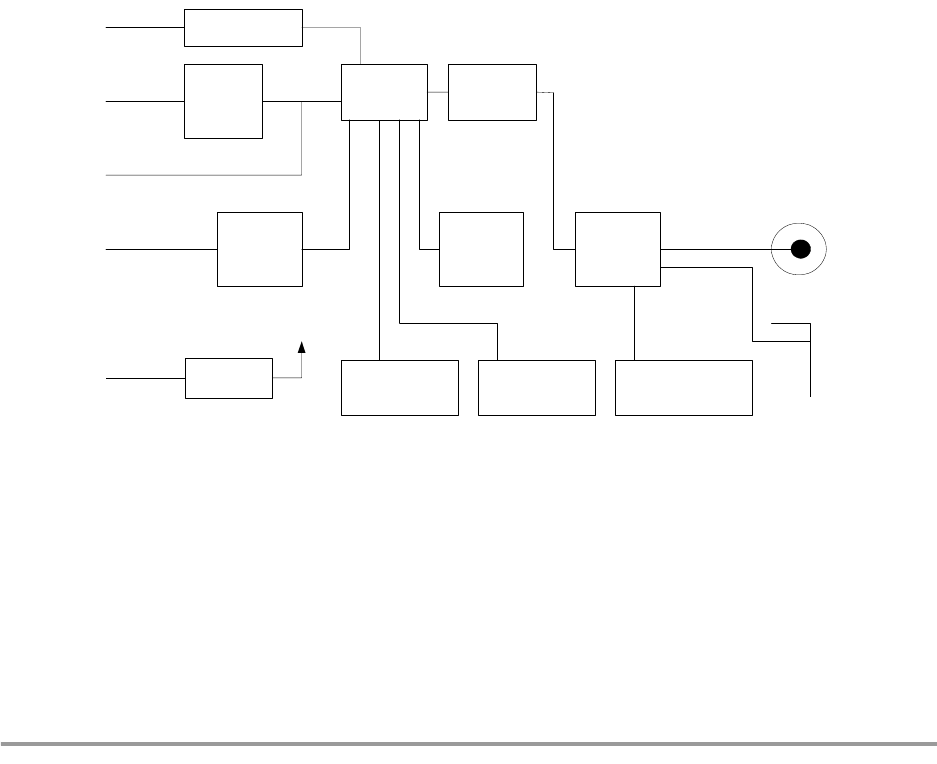
MOTOROLA Product Overview 2-5
Motorola Confidential Proprietary, NDA Required / Preliminary
Chapter 2
Product Overview
This section contains a brief overview of the Development Kit. More detailed information on the various
elements of the Development Kit is included in later sections and in the separate user’s guides included on
the CD.
2.1 Block Diagram
The following figure shows the Development Kit block diagram:
Figure 2-1. Block Diagram
2.2 Interfaces
The development kit features RS232, UART, and USB interfaces:
• RS232 interface: Programmable baud rate from 1200 to 921 Kbit.
• UART interface: 5-pin header with RxD, CTS, RTS, and GND, 3.3 V signaling, programmable
baud rate from 1200 to 921 Kbit, HCI UART transport layer.
USB
RS232
DC
Power
Input
UART
USB
RS232
Level
Shifter
CODEC
Modular Jack
MC71000 MC13180
MC13181 7 Status
LEDs Reset Switch Class ½
Antenna Jumper
EEPROM
Antenna
Diversity
Switch
F Antenna
Antenna
Connector

2-6 Development Platform Kit User Guide MOTOROLA
Motorola Confidential Proprietary, NDA Required / Preliminary
Product Overview
NOTE:
The UART and RS232 interfaces cannot operate simultaneously.
• USB interface: Full speed (12 Mbit/s) USB node device, HCI USB transport layer, 3.3 V operation,
self-powered, National USBN9604 USB controller.
The following list shows the USB limitations:
— USB interface is for evaluation purposes and only included for ease of use.
— Supports OpenUSBDI-compatible USB controllers. USB v1.1.
— Does not support Open HCI.
— Production release of the MC71000 will not support USB.
• Audio connections, with audio routed either to the CODEC or through the transport layer
2.3 Applications
The Development Kit supports the Headset application. A separate Headset User’s Guide is TBD.
2.4 ICs
The Development Kit is supplied with the following Bluetooth ICs from Motorola:
• MC71000 Bluetooth Baseband Controller IC
• MC13180 Bluetooth Low Power Wireless Data Transceiver IC
• MC13181 Wireless Power Management IC
Future Development Kit releases will contain the MRFIC2408 External Power Amplifier IC.
2.5 Software Tools
The Bluetooth Development Kit is accompanied by the following software tools:
• Bluetooth HCI Terminal
• Configuration manager
• DemoBench
The following sections describe briefly each of the software tools. A separate user’s guide for each tool is
included on the Development Kit CD.

Software Tools
MOTOROLA Product Overview 2-7
Motorola Confidential Proprietary, NDA Required / Preliminary
2.5.1 Bluetooth HCI Terminal
With the Bluetooth HCI Terminal you can interact with your Bluetooth hardware. The interface is similar
to that of an AT Terminal application when communicating with a modem. The Bluetooth HCI Terminal
makes it easy to send HCI commands from a computer to a Bluetooth device. Likewise, it is easy to
receive HCI responses from a Bluetooth device. Consequently, you can get hands-on experience with the
HCI. Or you can test your own Bluetooth hardware.
The Bluetooth HCI Terminal is accompanied by the Bluetooth HCI Terminal Guide, accessible from the
document overview on the CD:
2.5.2 Configuration Manager
The Configuration Manager is an application that allows you to handle the Development Kit file system.
With this tool, you can download firmware patches and set up a number of baseband and radio parameters
to exercise the board. All parameters are restorable and default settings are stored automatically.
The Configuration Manager is accompanied by a user’s guide, accessible from the document overview on
the CD.
2.5.3 DemoBench
The DemoBench is a demonstration tool that can be used for a number of purposes. You can send a file to
another Bluetooth device, “chat” with another Bluetooth device, and view link and packet statistics in a
real-time application.
The DemoBench is accompanied by a user’s guide, accessible from the document overview on the CD.

2-8 Development Platform Kit User Guide MOTOROLA
Motorola Confidential Proprietary, NDA Required / Preliminary
Product Overview

MOTOROLA Setup 3-9
Motorola Confidential Proprietary, NDA Required / Preliminary
Chapter 3
Setup
This section provides instructions for setting up the Development Kit hardware and software.
3.1 Setting Up Board
To get the board up and running, do the following:
1. Connect the board and PC via the UART (RS232) cable.
NOTE:
The first time you start up the board, you can only run UART, not USB.
2. Attach power supply to DC connector on board and connect to main electricity supply.
3. Insert the CD in the CD-ROM drive of your PC and follow the onscreen instructions.
3.2 Running UART
To run UART, do the following:
1. Get the board up and running as described above.
2. Download the UART application from the Configuration Manager on the CD.
3.3 Running USB
NOTE:
The first time you start up the board, you can only run UART, not USB.
Follow the above setup instructions.
To run USB, do the following:
1. Make sure the power is turned off the board.
2. Connect the board and PC via the UART (RS232) cable.
3. Attach power supply to DC connector on board and connect to main electricity supply.
4. Download the USB application from the Configuration Manager on the CD.

3-10 Development Platform Kit User Guide MOTOROLA
Motorola Confidential Proprietary, NDA Required / Preliminary
Setup
5. Within the Configuration Manager, go to Settings>Com Port and select the USB option.
6. Follow the instructions on screen to disconnect the UART (RS232) cable and connect the
USB cable.

MOTOROLA Hardware 4-11
Motorola Confidential Proprietary, NDA Required / Preliminary
Chapter 4
Hardware
This section provides information on various aspects of the Development Kit hardware. In addition,
Appendix A, “Board Diagram“, contains a diagram of the Development Kit board.
4.1 Signal and Connection Descriptions
The development kit contains the following connections, switches, and indicators:
• Power supply input
• Modular jack 4/4 connector for mono-audio speaker and microphone (headset application)
• RS232 interface
• UART interface
• USB interface
• Antenna connector
• JTAG allowing interface to MC71000 production test
• Reset switch
• Four control buttons for the headset application
• On/off switch
• Seven status LEDs
The power supplied for the development kit is DC with the ratings stated in the specifications.
An analog audio signal to be transmitted over the Bluetooth connection can be fed into the development kit
via the modular jack or as streaming audio through the host interface. It will be converted to digital data and
transmitted through the Bluetooth link. A digital audio signal received from a connected Bluetooth device
will be converted to an analog audio signal and available at the modular jack or as streaming audio through
the host interface (UART, SSI, SPI). The MC71000 has a Bluetooth Audio Signal Processor (BTASP) for
superior audio performance.
The RS232/UART interfaces can be used to transfer data and audio between a host and the Bluetooth device.
The firmware of the development kit can be upgraded through the RS232/UART interface.
The USB interface is a standard HCI USB interface. This interface can be used to connect the development
kit to a PC or other devices with PC-compatible USB connections.
The CODEC is attached to the MC71000 via the SPI (data) and SSI (streaming audio) interfaces.
The antenna connector is an SMA 50 ohm connection.

4-12 Development Platform Kit User Guide MOTOROLA
Motorola Confidential Proprietary, NDA Required / Preliminary
Hardware
The reset switch can be activated to re-initialize the entire system.
Four buttons are provided for embedded applications:
• Volume up
• Volume down
• Function 1 (connection etc.)
• Function 2 (this is an extra button)
Seven status LEDs are provided:
• Two application-specific LEDs
• Class 2
• 24 MHz/32 kHz
•RX/TX
•Power on
• Diversity (shows which antenna is being used)
4.2 Environmental
This section contains system level environmental information:
• Storage temperature (degrees centigrade):
—Min. -40
—Max +125
• Operating temperature (degrees centigrade):
—Min. -20
—Max +85
4.3 Mechanical
This section contains system level mechanical information:
• Length: 100 mm
• Width: 100 mm
• Height (PCB with components): 20 mm
• Layout, FR4, 6 layer: 1 mm
4.4 Electrical
This section contains electrical information:
• Input power supply requirements: 3.5-6.5 VDC

Electrical
MOTOROLA Hardware 4-13
Motorola Confidential Proprietary, NDA Required / Preliminary
• Audio input: 65m Vpp
• Audio output: 1.6 Vpp, modular jack 4/4 connector
The following table shows the current consumption measurements of the circuits of the MC71000
Bluetooth Baseband Controller and MC13180 Bluetooth Low Power Wireless Data Transceiver ICs.
Note that the table contains typical values.
4.4.1 Power Supply
The board is fed with power from on-board standard regulators.
The on-board power supply regulators should be fed with the supply provided, which generates the
following voltages for the board:
•1.85 V
•2.65 V
•3.3V
4.4.2 Reset Circuit
The board includes a push button for full system reset of the MC71000 and all peripherals.
4.4.3 Clocks
The clocks in the system are as follows:
• Sleep mode clock: 32.768 kHz.
• Active mode clock: 24 MHz from MC13180 radio module
The MC71000 includes an internal oscillator circuit for the 32.768 kHz sleep mode clock. Only an external
crystal and a few other components are needed.
Table 1: Current Consumption Measurements of MC71000 and MC13180 Circuits
DH5 asymmetric
RX 50.4 mA TX rate 57.6 kbits
RX rate 723.2 kbits
DH5 asymmetric
TX 48.5 mA TX rate 723.2 kbits
RX rate 57.6 kbits
DH5 symmetric 45.8 mA TX rate 433.9 kbits
RX rate 433.9 kbits
HV1 45.8 mA
HV3 27.8 mA
Total system in
low-power mode 0.130 mA

4-14 Development Platform Kit User Guide MOTOROLA
Motorola Confidential Proprietary, NDA Required / Preliminary
Hardware
4.4.4 Memory
The MC71000 has embedded memory of 256 Kbytes of ROM and 64 K of RAM. An image can be
uploaded from a host system, or a low-cost serial EEPROM (four-wire connection). For more information
on the contents and structure of the MC71000 memory, please refer to the Bluetooth Platform Solution
Embedded System User’s Guide. This is accessible from the document overview on the Development Kit
CD.
4.4.5 UART Interface
The UART interface is embedded in the MC71000. However, an external level converter is needed. For
this purpose, the MAX3237 1.0 Mbit level converter is used. The level converter is connected to the
MC71000 and a female 9-pin D-sub. The connection between the level converter and the MC71000 is
passed through a jumper block in order to aid debugging, and, if ever needed, to use a different type of
level converter.
4.4.6 USB Interface
The USB interface consists of the National USBN9604 USB device controller. A 3.3 V power supply is
used for the USBN 9604.
For information on the USB limitations of the Development Kit, see the section “USB Limitations”
4.4.7 CODEC Interface
The audio interface consists of the Xemics XE3006 CODEC, a 4-pin header and a 4/4p amp connector. As
to the power supply for the CODEC, both 1.8 V and 3.3 V are selectable by a “+” formation jumper.
Sampling rate is configured at 7.8125 kHz.
4.4.8 Antenna
The Development Kit contains an F entenna and an SMA 50 Ohm antenna connector.
4.5 Reference Designs
The Bluetooth Platform Solution reference designs include the following: Host optimized, host
non-optimized, and standalone (headset). Descriptions and schematics are included in the Bluetooth
Platform Solution Reference Designs document. This is accessible from the document overview on the
Development Kit CD.

MOTOROLA Limitations 5-15
Motorola Confidential Proprietary, NDA Required / Preliminary
Chapter 5
Limitations
This section deals with the known limitations of the Bluetooth Development Kit.
5.1 USB Limitations
The Bluetooth Development Kit has the following USB limitations:
• The USB interface is for evaluation purposes only. It is only included for the purpose of showing
full bandwidth.
• Supports OpenUSBDI-compatible USB controllers. USB V1.1.
• Does NOT support Open HCI.
• No USB logo certification.
• MC71000 does NOT support USB. USB controller is external USBN9604 from National.
For general information on USB, please see www.usb.org.

5-16 Development Platform Kit User Guide MOTOROLA
Motorola Confidential Proprietary, NDA Required / Preliminary
Limitations

MOTOROLA Regulatory 6-17
Motorola Confidential Proprietary, NDA Required / Preliminary
Chapter 6
Regulatory
This section contains regulatory statements, a list of the countries where the Development Kit will be type
approved, and information on what is needed by developers to obtain type approvals for their products.
6.1 Regulatory Statements
NOTE:
Users are not permitted to make changes or modify the system in any way.
Changes or modifications not expressly approved by the party responsible
for compliance could void the user’s authority to operate the equipment.
6.1.1 General
This product complies with any mandatory product specification in any country where the product is sold.
6.1.2 European Union (EU) and EFTA
This equipment complies with the R&TTE directive 1999/5/EC and has been provided with the CE mark
accordingly.
6.1.3 France
This equipment may only be used as a Class 2 device, not as a Class 1 device. Note also that only indoor
use is allowed.
6.1.4 Nederland
(Applies to 20dBm products only)
Niet voor gebruik in de buitenlucht.
Deze apparatuur is uitsluitend bedoeld voor gebruik binnenshuis.
This device is intended for evaluation and development purposes by professionals only and is NOT
for re-sale.

6-18 Development Platform Kit User Guide MOTOROLA
Motorola Confidential Proprietary, NDA Required / Preliminary
Regulatory
6.1.5 United States of America and Canada
Tested to comply with FCC Standards FOR HOME OR OFFICE USE. See FCC 47CFR part 15.19(b)(2)
This device complies with part 15 of the FCC rules and with RSS-210 / RSS-139 of the Industry Canada.
Operation is subject to the following two conditions: (1) This device may not cause harmful interference,
and (2) this device must accept any interference received, including interference that may cause undesired
operation. See FCC regulation CFR47 sec. 15.19(3).
This equipment has been tested and found to comply with the limits for a Class B digital device, pursuant
to part 15 of the FCC Rules. These limits are designed to provide reasonable protection against harmful
interference in a residential installation. This equipment generates, uses and can radiate radio frequency
energy and, if not installed and used in accordance with the instructions, may cause harmful interference to
radio communications. However, there is no guarantee that interference will not occur in a particular
installation. If this equipment does cause harmful interference to radio or television reception, which can
be determined by turning the equipment off and on, the user is encouraged to try to correct the interference
by one or more of the following measures:
• Reorient or relocate the receiving antenna
• Increase the separation between the equipment and receiver
• Connect the equipment into an outlet on a circuit different from that to which the receiver is
connected
• Consult the dealer or an experienced radio/TV technician for help
In order to comply with FCC RF Exposure requirements, a minimum separation distance of 20 cm must
always be maintained between the transmitter antenna and all persons during normal operation.
Note that any changes or modifications to this equipment not expressly approved by the manufacturer may
void the FCC authorization to operate this equipment.See FCC regulation CFR47 sec. 15.21.
6.1.6 Canada Compliance (Industry Canada)
To prevent radio interference to the licensed service, this device is intended to be operated indoors and
away from windows to provide maximum shielding. Equipment that is installed outdoors is subject to
licensing.
In French: Pour empêcher un brouillage radioélectrique au service faisant l'objet d'une licence, cet appareil
doit être utilisé à l'interieur et loin des fenêtres afin de founir un écran de blindage maximal. Au cas aù un
installation en plain air, le materiel doit faire l'objet d'une licence.
6.1.7 Singapore
This product complies with the standard Infocomm Development Authority of Singapore (IDA) TS SSS
amended by the Guidance notes on Bluetooth Type Approval Framework and has been approved by the
IDA under the Type Approval Certificate (TAC) number: Motorola TAC number TBD
The supplier of this equipment is responsible that the equipment can be used as described in the
accompanying documentation. Furthermore, the supplier is responsible for providing proper installation
and after-sales maintance of the equipment to meet the user's needs.
Under no circumstances is the IDA liable for the use, installation, or after-sales maintenance of the
equipment.
Regulatory Statements
MOTOROLA Regulatory 6-19
Motorola Confidential Proprietary, NDA Required / Preliminary
6.1.8 Brazil
Este equipamento opera em caráter secundário, isto é, não tem direito a proteção contra interferência
prejudicial, mesmo de estações do mesmo tipo, e não pode causar interferência a sistemas operando em
caráter primário.
6.1.9 Japan
6.1.10 Taiwan
ߎߩᯏེߩ↪ᵄᢙᏪߢߪޔ㔚ሶࡦࠫ╬ߩ↥ᬺ⑼ቇක≮↪ᯏེߩ߶߆Ꮏ႐ߩㅧ
ࠗࡦ╬ߢ↪ߐࠇߡࠆ⒖േኻ⼂↪ߩ᭴ౝή✢ዪ (⸵ࠍⷐߔࠆή✢ዪ) ߮․ቯዊ
㔚ജή✢ዪ (⸵ࠍⷐߒߥή✢ዪ) ߇ㆇ↪ߐࠇߡ߹ߔޕ
1 ߎߩᯏེࠍ↪ߔࠆ೨ߦޔㄭߊߢ⒖േ⼂↪ߩ᭴ౝή✢ዪ߮․ቯዊ㔚ജή✢ዪ߇ㆇ
↪ߐࠇߡߥߎߣࠍ⏕ߒߡߊߛߐޕ
2 ਁ৻ޔߎߩᯏེ߆ࠄ⒖േ⼂↪ߩ᭴ౝή✢ዪߦኻߒߡ㔚ᵄᐓᷤߩ߇⊒↢ߒߚ႐ว
ߦߪޔㅦ߿߆ߦ↪ᵄᢙࠍᄌᦝߔࠆ߆ߪ㔚ᵄߩ⊒ࠍᱛߒߚޔਅ⸥ㅪ⛊వߦߏㅪ
⛊㗂߈ޔᷙା࿁ㆱߩߚߩಣ⟎╬ (߃߫ޔࡄ࠹࡚ࠖࠪࡦߩ⸳⟎ߥߤ) ߦߟߡߏ⋧⺣ߒ
ߡߊߛߐޕ
3 ߘߩઁޔߎߩᯏེ߆ࠄ⒖േ⼂↪ߩ․ቯዊ㔚ജή✢ዪߦኻߒߡ㔚ᵄᐓᷤߩ߇⊒↢
ߒߚ႐วߥߤ߆߅࿎ࠅߩߎߣ߇߈ߚߣ߈ߪޔᰴߩㅪ⛊వ߳߅วࠊߖਅߐޕ
ㅪ⛊వ㧦03-3440-3311 (+81-33440-3311)

6-20 Development Platform Kit User Guide MOTOROLA
Motorola Confidential Proprietary, NDA Required / Preliminary
Regulatory
6.2 Obtaining Type Approvals
Customers of Motorola Bluetooth chipsets will face some Bluetooth qualification and regulatory
requirements for their products. The following lists the requirements for the major markets as defined by
Digianswer/Motorola as tier 1 countries: Australia, Canada, Europe (15 + 4 EFTA countries), Japan, New
Zealand and US. A number of other countries worldwide will accept the test reports made for Europe
and/or US approvals.
Motorola chipsets (radio/baseband) are pre-qualified as Bluetooth components. Also any variants of
Motorola software stacks will be pre-qualified. The assumption of pre-qualification provides that
customers will implement the radio module (radio chip including surrounding components and print
layout) without any changes.
6.2.1 Requirements for Bluetooth Qualification
Baseband chipset will be used as a pre-qualified component and do not require re-testing.
Any incorporated variant of Motorola software stack will be used as a pre-qualified component and do not
require re-testing.
Radio will need to be re-tested in the product layout for the following 8 (of 16) test cases:
If changes are made to the Development Kit radio module BOM or layout, all 16 Bluetooth test cases will
be required to be re-tested. Depending on the nature of changes to the radio, re-testing might only be
necessary in normal temperature. This has to be decided by the BQB in each case.
6.2.2 Requirements for regulatory type approvals:
The following regulatory testing needs to be made:
• For CE-marking: EN 300 328-2 (emission), EN 301 489-17 (EMC), EN 60950 (safety)
• For Japan approval: ARIB T-66.
• For FCC grant: CFR47 part 15.205, 15.209 and 15.247 (except 15.247e: processing gain)
NOTE:
As Motorola radios will be approved by FCC as radio modules and the
Table 6-1.
TRM/CA/04/E TX Output Spectrum-Frequency range
TRM/CA/08/E Initial Carrier Frequency Tolerance
TRM/CA/09/E Carrier Frequency Drift
TTRC/CA/01/E Out-of-Band Spurious Emissions-radiated
RCV/CA/02/E Sensitivity-multi-slot packets
RCV/CA/03/E C/I performance
RCV/CA/04E Blocking performance
TP/PHYS/TRX/BV-05-C Symbol rate

Obtaining Type Approvals
MOTOROLA Regulatory 6-21
Motorola Confidential Proprietary, NDA Required / Preliminary
FCC testing can be avoided for regulatory purposes for radio modules,
provided no changes are made to the radio module BOM or layout, it will
still be necessary to perform the Out-of-Band Spurious
Emissions-radiated-test of part 15.209.
The product might be subject to additional product specific regulations, such as PSTN regulations and
other.
Type approval applications have to be filed to the national authorities for each product.
Documentation submitted for type approvals can vary from country to country, but will in general include:
test reports, pictures, BOM, schematics, PCB layouts, product descriptions (block diagrams), antenna
information, SAR statements (see below), label/manual information (legal text) and manufacturer
information.
Both in Europe and US regulators are currently working on new sets of rules for combined radio
equipment as well as rules for SAR. Test requirements for SAR (including combined radio) will most
likely be topical within the next year.

6-22 Development Platform Kit User Guide MOTOROLA
Motorola Confidential Proprietary, NDA Required / Preliminary
Regulatory

MOTOROLA A-1
Motorola Confidential Proprietary, NDA Required / Preliminary
Appendix A
Board Diagram
The following pages show a diagram of the Development Kit board.
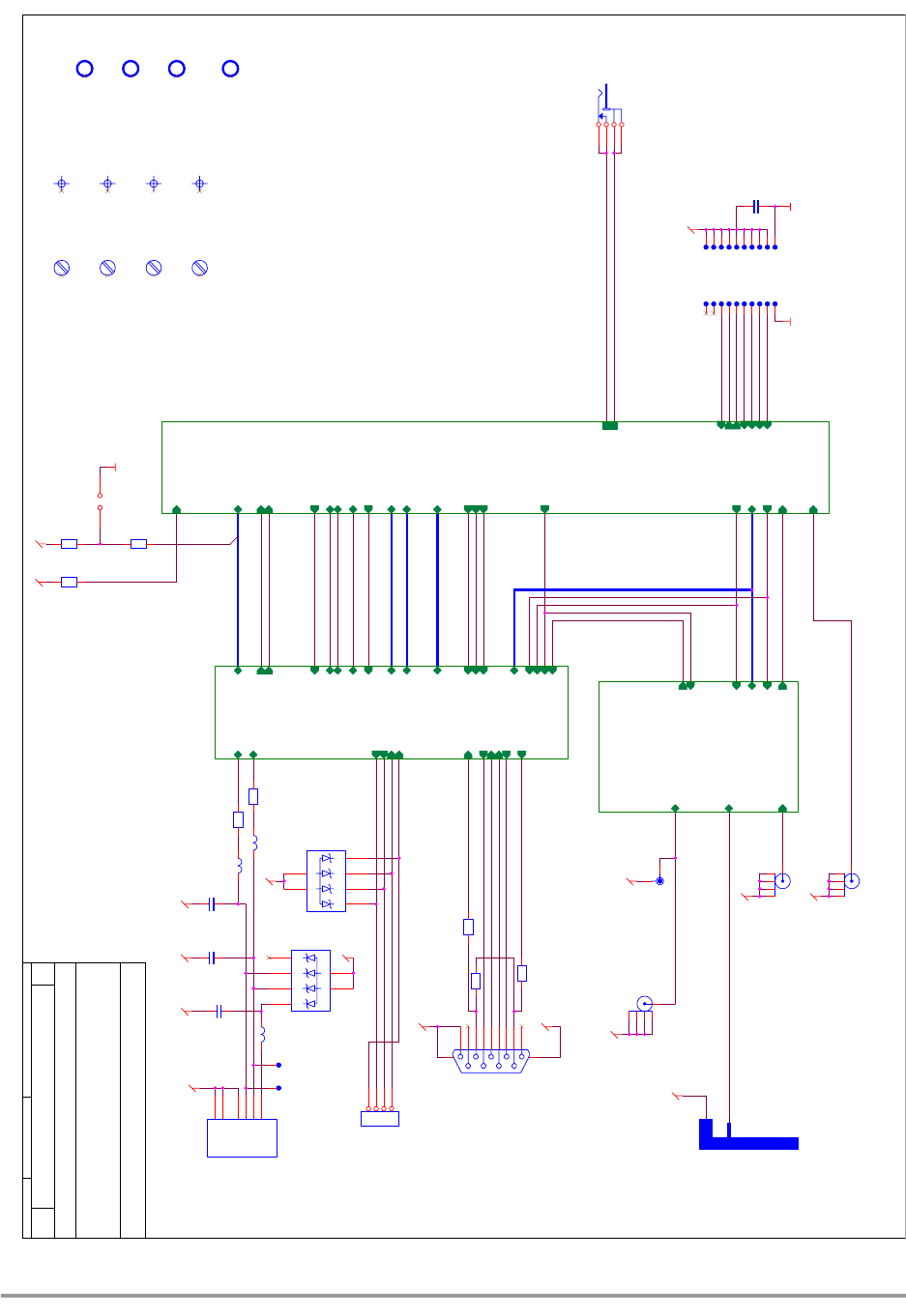
A-2 Development Platform Kit User Guide MOTOROLA
Motorola Confidential Proprietary, NDA Required / Preliminary
RTS
TXD
RXD
CTS
RFNET28
RxTx_SW
0dBm/20dBm
MIC-
EAR-
MIC+
EAR+
D[0..7]
GPIO_B11
RTCK
WE
TDI
A0
GPIO_B10
D7
TMS
MAIN-
TRST
TDO
GPIO_C9
SPI0[0..3]
SSI[0..4]
JTAG_RESET
REFCLK
Power ON
BT[1..9]
TCK
UART[0..3]
CS0
CLK0
OE
Reset
REFCTRL
MAIN+
DIVERSITY
RFNET29
VDD_EIM
HVDD1V85HVDD1V85
Title
Size Document Number Rev
Date: Sheet of
C o n f i d e n t i a l I n f o r m a ti o n
This document contains Digianswer A/S confidential and proprietary information, which you are not
entitled to reproduce or disclose to any third party without the prior written consent of Digianswer A/S.
© Digianswer
80000488000_R0404.DSN R04.04
VEGA DK: Polaris peripherals (DIG488-4)
Digianswer A/S
Skalhuse 5
DK-9240 Nibe, Denmark
Telephone: +45 96710000 Fax: +45 98350052 http://www.digianswer.com
A3
15Friday, May 03, 2002 CLL
2001-2002
UART
USB
3.5 - 5.5 VDC
AUDIO
interface
Modular 4/4
Power Supply
Placed i matrix 2x10 @0,1''
ANTENNA
MAIN SYSTEM OSC.
Sleep mode OSC
A101
Primus datum point (Compside)
TP111
TP114
J105
USB Serie-B
VUSB
1
DATA-
2
DATA+
3
GROUND
4
SHIELD1
5
SHIELD2
6
HOLE102
np hole ø2.2mm
CO104
PCB Corner Mark
TP124
TP123
TP120
J100
DC
3
2
1
4
L102
Not Mounted
TP103
IC102
MMQA5V6T1
Not Mounted
C1
6
A1 5
C2
4
C3
3A2 2
C4
1
R109
18R
A102
Secundary fiducial point (Compside)
TP115
R104 0R
R106
10K
HOLE103
np hole ø2.2mm
J109
Not Mounted
1
2
5
3
4
CO102
PCB Corner Mark
J106
4/4p
1
1
2
2
3
3
4
4
TP107
TP112
J103
9p Female Ang
5
9
4
8
3
7
2
6
1
m1 m2
TP121
TP104
C105
22pF
TP106
J108
Not Mounted
1
2
5
3
4
TP116
A103
Secundary fiducial point (Soldside)
Sheet 3
Polaris peripherals
D[0..7]
MIC+
TXD
CTS
RXD
RTS
EAR+
EAR-
GPIO_B11
GPIO_B10
CLK0
UART[0..3]
GPIO_C9
SSI[0..4]
SPI0[0..3] MIC-
Power ON
Reset
A0
CS0
OE
WE
REFCTRL
D-
D+
RxTx_SW
0dBm/20dBm
DIVERSITY
BT[1..9]
BT_WAKEUP
Ri
TP109
HOLE104
np hole ø2.2mm
CO101
PCB Corner Mark
TP113
TP102
Testpoint Coax (Soldside)
TP122
C106
1µF
TP117
C104
22pF
L100
0R
R110
18R
CO103
PCB Corner Mark
R103
0R
Not Mounted
C100
100nF
R100
10K
J107
2p
1 2
TP118
Sheet 4
RF Front
BT[1..9]
Antenna 1
REFCLK
REFCTRL
Antenna 2
DIVERSITY
RxTx_SW
0dBm/20dBm
13MHz_OSC
J102
SMA Receptacle, Female
1
2
5
3
4
BARCODE101
Label 21*6mm Test BarCode
TP110
HOLE101
np hole ø2.2mm
R107
10K
L101
0R
TP105
IC100
MMQA5V6T1
C1 6
A1
5C2 4
C3 3
A2
2
C4 1
R105 0R
Sheet 2
Polaris
TDI
TMS
TCK
TTS
RTCK
BT[1..9]
SSI[0..4]
UART[0..3]
SPI0[0..3]
TRST
GPIO_B11
GPIO_B10
GPIO_C9
REFCTRL
CLK0
D[0..7]
TDO
REFCLK
MAIN-
MAIN+
Power ON
Reset
CS0
OE
WE
A0
DIVERSITY
JTAG_RESET
0dBm/20dBm
32kHz_OSC
TP119
ANT100
F_Antenna
TP108
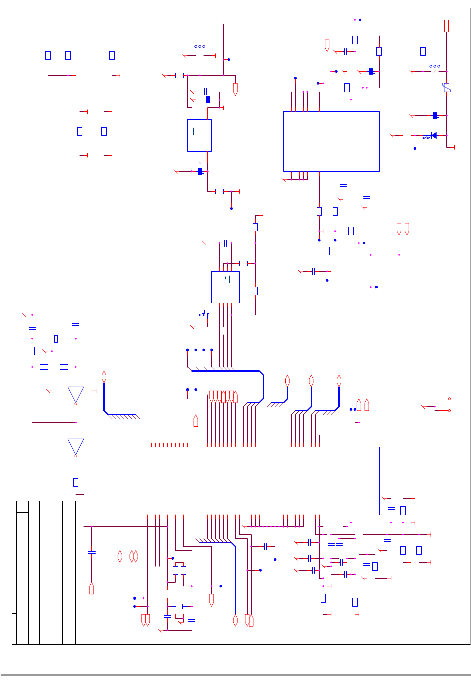
MOTOROLA A-3
Motorola Confidential Proprietary, NDA Required / Preliminary
D7
CS0
EXTAL
REFCLK
SPI1[0..3]
0dBm/20dBm
BTCLK
WE
GPIO_B10
OE
REFCTRL
SPI10
D[0..7]
SPI11
GPIO_C9
SPI12
CS1
SPI13
S_inv
GPIO_B11
SPI10
RESET
SPI11
SPI12
SPI13
SPI13
SPI12
SPI11
CLK0
SPI0[0..3]
Q2
PWM
SPI10
DIVERSITY
D0
S_inv
BT1
BT2
BT5
BT7
BT9
BT3
BT6
BT8
BT[1..9]
SSI0
D1
SSI2
SSI1
SSI3
SPI03
GPIO_B3
SPI02
SPI00
SSI4
SPI01
SSI[0..4]
D2
D3
BT4
D4
UART0
UART1
UART3
UART2
Q2
UART[0..3]
D5
0dBm/20dBm
D6
XTAL
PWM
A0
SPI0[0..3]
MAIN+
MAIN-
UART[0..3]
GPIO_B11
GPIO_B10
BT[1..9]
SSI[0..4]
D[0..7]
GPIO_C9
TRST
RESET
REFCLK
REFCTRL
CLK0
OE
WE
0dBm/20dBm
Power ON
TDI
TMS
TCK
TTS
TDO
RTCK
CS0
DIVERSITY
JTAG_RESET
32kHz_OSC
BVcc
VCC_RF
VCC
HVDD1V85
HVDD1V85
VCC
HVDD1V85
VccCodec
HVDD3V3
VCC
VCC_PA
VCC
HVDD3V3
HVDD3V3
3V3_USB
HVDD3V3 3V3_UART
VCC_LED
HVDD3V3
HVDD1V85
HVDD3V3
AVcc
HVDD3V3
HVDD1V85 AVcc
HVDD3V3
HVDD3V3
VDD_EIM
Title
Size Document Number Rev
Date: Sheet of
C o n f i d e n t i a l I n f o r m a ti o n
This document contains Digianswer A/S confidential and proprietary information, which you are not
entitled to reproduce or disclose to any third party without the prior written consent of Digianswer A/S.
© Digianswer
80000488000_R0404.DSN R04.04
VEGA DK: Polaris (DIG488-4)
Digianswer A/S
Skalhuse 5
DK-9240 Nibe, Denmark
Telephone: +45 96710000 Fax: +45 98350052 http://www.digianswer.com
A3
25Friday, May 03, 2002 CLL
2001-2002
Battery
Memory
R216
Not Mounted
J200
3p
1
2
3
S201
Switch
1
2
3
C216
10pF
C238
1.0pF
R232
Not Mounted
R206
10K
C217
100nF
C203
100µF
C228
1µF
TP212
R222
0R
C210
1µF
TP206
TP221
TP213
C218
100nF
R236
Not Mounted
TP209
R231
500mA
1 2
R221 0R
C208
100nF
J201
1p
1
1
C235
Not Mounted
TP224
C225
100nF
X200
32.768KHz
R226 0R
IC201
MC71000
TRST_B
K10
TDI
J10
TDO
H9
TMS
H8
TCK
G7
MODE0
G9
MODE1
F6
REFCLK J6
REFCTRL K4
RESETIN_B
F10
CS0_B
A3
Frame synch BT1 K7
RxD BT2 J7
TxD BT3 K8
RxTxEN BT4 J8
SPI clk BT5 K6
SPI_en BT6 K5
SPI do/SPI di BT7 J5
PWM0 / TX_en / GPO0 BT8 H6
PWM1 / PA_en / GPO1 BT9 H7
VDDpa H5
GNDcore_I1_EIM F3
EXTAL J9
XTAL K9
GNDcore_I2_EIM H4
GNDcore_I3 F9
GNDcore_I4_EIM D4
VDDcore_I1_EIM F2
VDDcore_I2_EIM J4
VDDcore_I3_EIM K3
VDDcore_I3 F8
GNDpc C7
VDDpc B7
VDDpb C8
GNDpb D8
SSI_STCK
A9
SSI_STFS
C9
SSI_STD
B9
SSI_SRCK
A10
SSI_SRFS
C10
SSI_SRD
B10
SPI_0_SS_B
B8
SPI_0_SCK
D9
SPI_0_MISO
E8
SPI_0_MOSI
D10
SPI_1_SS_B
D6
SPI_1_SCK
A6
SPI_1_MISO
B6
SPI_1_MOSI
C6
CLK0
E9
TXD
B5
RXD
A7
CTS_B
A5
RTS_B
A8
TTS
G8
CS1_B
C3
A0
B3
A1
E4
A2
A2
A3
D3
A4
F5
A5
B2
A6
A1
A7
B1
A8
C2
A9
C1
A10
D2
A11
D1
D0
F1
D1
G4
D2
G3
D3
G1
D4
G2
D5
H3
D6
H1
D7
H2
RTCK
H10
GNDmisc_I1 G6
VDDmisc_I1 G10
OE_B B4
WE_B A4
GPIO_B10 F7
GPIO_B11 E7
GPIO_B12 E10
CLK1
E5
GPIO_C9 C5
OSC32k D5
SYSCLK E6
BTCLK D7
VDD_I3_EIM K1
VDD_I2_EIM E1
VDDcore_I4_EIM C4
VDD_I4_EIM K2
GNDcore_I3_EIM J3
GND_I4_EIM J2
GND_I3_EIM J1
GND_I2_EIM E2
GND_I7_EIM F4
VDD_I7_EIM E3
GNDpa G5
R233
Not Mounted
R242
7.5R R215 0R
R209
1.5R
C230
100nF
IC205
AT25HP512-10CI-1.8
CS 1
SO 2
WP
3
GND
4SI 5
SCK 6
HOLD
7VCC
8
J202
1p
1
1
X201
Not Mounted
TP218
R219 0R
TP201
R240
10M
R207 1.0K
R2410R
C220
100nF
TP217
C212
10pF
R205
470R
R223
0R
R220 0R
TP222
D203
Green LED
C236
Not Mounted
TP220
IC206A
Not Mounted
1 6
52
TP225
C224
100nF
C207
100nF
C214
3.3µF
TP214
J204
3p
1
2
3
R210
10M
TP215
C239
3.3µF
C229
100nF
C237
1.0pF
TP211
C213
100nF
R229
10K
TP202
R204
1.5R
C234
100nF
C226
100nF
R211
0R
R213
10K
R218
1.0R
R234
Not Mounted
TP204
C205
6.8µF
R217
Not Mounted
TP223
TP226
R230
1.5K
TP219
R203
1.0K
C206
100nF
TP216
C227
100nF
IC206B
Not Mounted
3 4
COT201
Track in PCB
TP200
IC202
MC13181
VCC1
3
Vin+
24
Vin-
23
HysteresisSelect
21
DelayCap 9
Q1_b
10 S INV
6
Q2
11
S OR
12
2V65_ENABLE
17 1V85_ENABLE
18
3V0/3V3 sel
14
3V0/3V3 ENABLE
13
AGND1 4
OUT3V0/3V3 7
OUT2V65 1
OUT1V85 19
RESET_b 15
Detect 22
REFOUT 2
VCC2
8
Shutdown
16
AGND2 20
SGND 5
EP EP
IC203
LP2981IM5-3.3
IN
1OUT 5
ON/OFF
3GND 2
NC 4
TP210
TP207 TP208
TP203
R214
0R
R239 0R
R212
100K

A-4 Development Platform Kit User Guide MOTOROLA
Motorola Confidential Proprietary, NDA Required / Preliminary
UART3
UART2
UART0
UART1
SPI00
SPI01
SPI02
SPI03
SPI00
SPI01
SPI02
SPI03
SSI1
SSI2
SSI3
D0
SSI4
D1 D2
SSI0
D3 D7D6D5D4
BT[1..9]
BT8
SSI4
SSI2
GPIO_B11
D3
CS0
OE
WE
D2D1
D7
D0
A0
UART0
D2
D1
D6
UART1
D4
D0
D3
D[0..7]
D5
UART[0..3]
UART2
GPIO_C9
UART3
SSI[0..4]
SSI3
SSI1
SPI0[0..3]
SSI0
UART[0..3]
SPI0[0..3]
SSI[0..4]
D[0..7]
GPIO_B10
GPIO_C9
D+
D-
D[0..7]
GPIO_B11
MIC-
DIVERSITY
BT[1..9]
MIC+
RESET
A0
OE
WE
EAR+
EAR-
RxTx_SW
CS0
CLK0
0dBm/20dBm
TXD
CTS
RTS
RXD
BT_WAKEUP
Ri
Power ON
REFCTRL
3V3_UART
VccCodec
VCC_LED VCC_LED VCC_LED VCC_LED
BVcc
BVcc
VCC_LED VCC_LED
3V3_USB
3V3_UART
BVcc
3V3_USB
VCC
BVcc
VDD_EIM
Title
Size Document Number Rev
Date: Sheet of
C o n f i d e n t i a l I n f o r m a ti o n
This document contains Digianswer A/S confidential and proprietary information, which you are not
entitled to reproduce or disclose to any third party without the prior written consent of Digianswer A/S.
© Digianswer
80000488000_R0404.DSN R04.04
VEGA DK: Polaris peripherals (DIG488-4)
Digianswer A/S
Skalhuse 5
DK-9240 Nibe, Denmark
Telephone: +45 96710000 Fax: +45 98350052 http://www.digianswer.com
A3
35Friday, May 03, 2002 CLL
2001-2002
SRFS
STCK
SRD
STFS
SYSTEM RESET
SPI_0_SS
SPI_0_SCK
SPI_0_MISO
SPI_0_MOSI
STD
Rx / Tx
RDK specific
24MHz / 32kHz F-antenna /
SMA Connector
Class1 / Class2
Power ON
+/- -/+ FUNC 1 FUNC 2
Codec
USB
Level shifter
Keys
X300
24.000MHz
D300
Green LED
IC301
MAX3237EAI
C1+
28
C1-
25
C2+
1
C2-
3
T1IN
24
T2IN
23
R1OUT
21
R2OUT
20
VCC 26
V+ 27
V- 4
GND 2
T1OUT 5
T2OUT 6
R1IN 8
R2IN 9
T3IN
22
T4IN
19
T5IN
17
T3OUT 7
T4OUT 10
T5OUT 12
R1OUTB
16
R3OUT
18 R3IN 11
MBAUD 15
SHDN 14
EN
13
R328
560K
D306
BAT54
21
TP300
C305
100nF
R308
470R
R307
470R
C321
390pF
TR302B
BC847BS
5
34
TP328
TP333
TP342
R317
10K
R302
0R
TP302
TP322
R321
10K
TP313
R334
470R
R324
10K
G
R
D304
Red/Green LED SMD
1
4 3
2
TR302A
BC847BS
2
61
L301
220µH
R300
2.2K
C325
33pF
C309
100nF
IC307
USBN9604SLB
CS
19
RD
20
WR/SK
21
INTR
22
DRQ
23
DACK
24
A0/ALE/SI
25
D0/S0
26
D1
27
D2
28
D3
1
D4
2
D5
3
D6
4
D7
5
RESET
6
AGND 7
V3.3 8
D+ 9
D- 10
GND1 11
VCC 12
GND 13
MODE1
14 MODE0
15 XIN 16
XOUT 17
CLKOUT 18
C323
33pF
D301
Red LED
C303
100nF
G
R
D303
Red/Green LED SMD
1
4 3
2
TP329
C313
1µF
S305
SPST
TP303
TP340
TP341
TR301A
BC847BS
2
61
TR300B
BC847BS
5
34
R325
10K
TP336
R337
10K
R318
10K
TP324
TP323
TP344
IC310
Not Mounted
1
2
4
53
TP316
R322
10K
C324
4.7µF
D307
BAT54
21
S301
SPST
TP309
S302
SPST
R336
470R
R304
Not Mounted
L302
220µH
C311
1µF
R340
10K
TP339
R320
1.5K
R342 0R
J300
2*4p
1 2
3 4
5 6
7 8
D308
BAT54
2 1
TP335
C308
100nF
S306
Switch
1
2
3
TP325
TP330
R331
470R
TP338
TR301B
BC847BS
5
34
C302
1µF
R319
10K
C304
100nF
TP304
TP308
R310
470R
R329
100R
TP312
TP321
S303
SPST
IC300
XE3006
MCLK
1
SMAD
2SMDA
3
VDD1
4
NRESET
5
VSSA1_ 6
VREG 7
VREF 8
VSSA1 9
VSSD1
10
VMIC 11
AIN 12
VSSA2
13
AOUTN 14
VDDA2
15
AOUTP 16
FSYNC
17
BCLK
18
SDO
19
SDI
20
MISO
21 SCK
22 SS
23
MOSI
24
TP301
R323
10K
G
R
D302
Red/Green LED SMD
1
4 3
2
IC309
NC7S32M5
1
2
4
53
TP326
TP331
TP337
C320
100nF
TP311
C300
1µF
R335
10K R338
10K
R332
470R
R301
18R
C322
33pF
R306
470R
TP343
TP307
C306
100nF
C314
1µF
TP332
R333
470R
R316
10K
COT300
Track in PCB
TP327
TP334
S304
SPST
R326
10K
G
R
D305
Red/Green LED SMD
1
4 3
2
R341
10K
R339
10K
R330
470R
C326
22pF
TP310
C310
100nF
IC308
NC7S32M5
1
2
4
53
TP315
TR300A
BC847BS
2
61
TP305
TP306

MOTOROLA A-5
Motorola Confidential Proprietary, NDA Required / Preliminary
RFNET11 R FNET12
RFNET14
RFNET7
RFNET6
RFNET18
RFNET19
RFNET17
RFNET20
RFNET4
RFNET21
RFNET22
RFNET9
RFNET26
RFNET24
RFNET27
RFNET23
RFNET25
RFNET16
RFNET3 RFNET8
BT5
BT1
BT3
BT4
BT5
BT3
BT9
BT4
BT2
BT6
BT6
BT7
RFNET10
BT7
BT8
BalunNET1
IC406.6:C408.1:3.17mm:3.20mm:C408.1:R400.2:0.73mm:0.76mm:R400.2:R400.1:1.87mm:1.90mm:R400.1:COT401.1:0mm:0.10mm:C408.1:C407.1:0mm:0.1mm
BalunNET2
IC406.8:C408.2:3.17mm:3.20mm:C408.2:R402.2:0.73mm:0.76mm:R402.2:R402.1:1.87mm:1.90mm:R402.1:COT402.1:0mm:0.10mm:
BT[1..9]
BT1
BT2
RxTx
DIVERSITY
REFCTRL
REFCLK
RxTx_SW
BT[1..9]
Antenna 1
Antenna 2
0dBm/20dBm
13MHz_OSC
VCC_LED
VCC_LED
VCC_PA
VCC_RF
VCC_PA
VCC_LED
VCC_LED
VCC_RF
VCC_RF
VCC_RFVCC_RF VCC_RFVCC_RF
VCC_RF
VCC_RFVCC_RFVCC_RF
AVcc
Title
Size Document Number Rev
Date: Sheet of
C o n f i d e n t i a l I n f o r m a ti o n
This document contains Digianswer A/S confidential and proprietary information, which you are not
entitled to reproduce or disclose to any third party without the prior written consent of Digianswer A/S.
© Digianswer
80000488000_R0404.DSN R04.04
VEGA DK: RF-front (DIG488-4)
Digianswer A/S
Skalhuse 5
DK-9240 Nibe, Denmark
Telephone: +45 96710000 Fax: +45 98350052 http://www.digianswer.com
A3
45Friday, May 03, 2002 CLL
2001-2002
Layer 1 : 64ohm Track wide =413µm BalunNETx
Layer 1 : 50ohm Track wide = 663µm (RFNETxx)
Er = 4,4
R400
620R
L400
1.0nH
L403
3.3nH
TP414
C430
100nF
R409
0R
C431
100nF
TP407
TP411
R417
0R
IC401
MRFIC2408
Vpc
10 EN
1RF_IN
12
Q1_Bias_R
3
GND
2GND1 4
VCC
11 RF_OUT1 8
RF_OUT 9
GND2 6
GND3 7
Q2_Bias_R 5
EP EP
C412
1.0pF
TP402
C436
Not Mounted
C418
15pF
IC408B
NC7WZ14
3 4
C426
1.5nF
IC407
AS169-73
J3 1
GND 2
J1
5
J2 3
V2
6V1
4
R403
24K
COT402
C439
1.5nF
R405
Not Mounted
L401
12nH
R422
Not Mounted
L402
1.5nH
R408
0R
TP409
C424
6.8pF
C403
22pF
TP403
C419
Not Mounted
R424
3.3R
C421
15pF
R402
620R
C400
390pF
R416
0R
Not Mounted
C435
22pF
R410
0R
Not Mounted
IC406
MC13180
GND-LNA1 1
RFIN 2
GND-LNA2 3
EXT-PA-EN 4
VCC-PA 5
PAO-P 6
GND-PA 7
PAO-M 8
GPO-o
9
EXT-PA-DRV 10
TIN-JP
11
TIN-JM
12
TMON-P
13
TMON-M
14
GND-LIM 15
VCC-LIM 16
GND-DEMOD 17
VCC-DEMOD 18
GND-XTAL
19
XTAL-BASE
20
XTAL-EMITTER
21
VCC-XTAL
22
DC-LF2 23
DC-LF1 24
VCC-DC 25
Rx-Tx-EN
26
PACKET-DATA
27 FS-OUT
28
DATA-CLK
29
SPI-CLK
30
SPI-DATA
31
SPI-EN
32
RESET
33
VDD-INT
34
VDD 35
GND
36
VCC-CP 37
GND-CP 38
MN-LF 39
VCC-PRE 40
GND-PRE 41
VCC-VCO 42
GND-VCO 43
GND-MOD 44
VCC-MOD 45
VCC-MIX 46
GND-MIX 47
VCC-LNA 48
GND-Ep Ep
C437
Not Mounted
IC402
AS196-307
Vcc 1
Vctl
2
J1
3J2 12
J3 9
NC1 15
NC2
6
NC3
7
GND7
16
GND0 4
GND1 5
GND2 8
GND3 10
GND4
11
GND5
13
GND6
14
GND-Ep
Ep
IC403
AS196-307
Vcc
1Vctl 2
J1 3
J2
12
J3
9NC1
15 NC2 6
NC3 7
GND7 16
GND0
4
GND1
5
GND2
8
GND3
10
GND4 11
GND5 13
GND6 14
GND-Ep Ep
C411
Not Mounted
C417
Not Mounted
C402
1.5nF
TP404
TP408
IC405
AS163-73
J3
3
GND
2J1 5
J2
1
V2 4
V1 6
COT401
C406
0.82pF
C410
22pF
IC404B
NC7WZ14
3 4
C438
1.0pF
C427
6.8pF
R421
Not Mounted
C404
33pF
C4073.3pF
R418
0R
Not Mounted
TP413
C432
22pF
IC404A
NC7WZ14
16
52
X400
13.000MHz
R411
0R
R415
Not Mounted
C413
Not Mounted
C416
1µF
C433
22pF
C428
100nF
C422
22pF
TP405
C415
1.5nF
C420
33nF
R413
0R
C405
22pF
R420
10K
TP401
C429
100nF
C425
100nF
C401
10nF
TP412
C423
100nF
Z400
LFSN30N17C2450B
GND3
3
IN
4OUT 2
GND1
1
IC408A
NC7WZ14
1 6
52
R404
Not Mounted
R414
Not Mounted
TP406
C414
270pF
R401
100R
C409
22pF
C408
1.0pF
R423
0R
C434
22pF
TP400

A-6 Development Platform Kit User Guide MOTOROLA
Motorola Confidential Proprietary, NDA Required / Preliminary