Digital Recorders 901-1700-000 Wireless Data Transfer Option User Manual Wireless OM manual
Digital Recorders Inc Wireless Data Transfer Option Wireless OM manual
Digital Recorders Wireless Data Transfer Operations and Maintenance Manual

Digital Recorders
WIRELESS DATA TRANSFER
Operations and
Maintenance Manual
P/N 597-0002-000
Release 5/15/01
©2001 Digital Recorders, Inc. All rights reserved.

COPYRIGHT © 2001 DIGITAL RECORDERS, INC.
ALL RIGHTS RESERVED
No part of this manual may be reproduced or transmitted in any form electronic
or mechanical without the express written permission of Digital Recorders, Inc.
The information contained in this manual is updated regularly. Every effort has
been taken to ensure the accuracy of the information within this manual. Digital
Recorders, Inc. cannot assume liability for losses of any nature arising from
errors or omissions.
Printed in the US
NOTE: This equipment complies with Part 15 of the FCC rules. Operation is subject to the
following two conditions: (1) This device may not cause harmful interference; and (2)
This device must accept any interference received, including interference that may
cause undesired operation.
WARNING: Changes or modifications not expressly approved by Digital Recorders,
Inc. may void the user’s authority to operate this equipment.
WARNING: To satisfy FCC RF exposure requirements for mobile transmitting
devices, a separation distance of 32cm or more should be maintained
between the antenna of this device and persons during device
operation. To ensure compliance, operations at closer than this
distance is not recommended.

To our valued customer;
Digital Recorders is pleased to provide you with this Operations and
Maintenance Manual for your Wireless Data Transfer. We hope you will
find the information within both useful and informative.
Every effort has been made to ensure the information found in this manual
is accurate. If, however, you discover any errors, omissions or have any
suggestions for changes or improvements please contact us.
All of us at Digital Recorders wish to sincerely thank-you for choosing the
Talking Bus® family of products. We are continually striving to provide the
highest quality products available along with the best customer service
possible!
We look forward to working with you. If you have any questions you can
visit us on the web at www.talkingbus.com or contact us at 1-800-222-
9583.
“The Transit Market's choice for automated voice announcement
systems and related products and services." ™
Yours Truly,
Tanya L. Johnson
General Manager and Vice President

Wireless Data Transfer SECTION 1
1-1
GENERAL INFORMATION
1.1 ABOUT THIS MANUAL
This manual describes the theory of operation, system components, connections,
and checkout procedure for the Digital Recorders Wireless Data Transfer option,
which is an add-on to the DR500C ‘Talking Bus’ product.
1.2 ABOUT THE WIRELESS DATA TRANSFER OPTION
1.2.1 INTRODUCTION
The Wireless Data Transfer option enables data to be wirelessly
transmitted within a localized area between one or more base-station PC’s
and vehicle-mounted DR500C ‘Talking Bus’ units. Depending upon
system configuration, data transfer may be one-way (vehicles to PC or
vise-versa) or two-way communication. This wireless communication link
eliminates the need to physically transport the associated data to and/or
from each vehicle via a PCMCIA card or other media.
Wireless communication is provided using 2.4Ghz, Spread Spectrum
Frequency Hopping (SSFH) technology. This technology provides high
speed, secure, and reliable communication which is highly immune to
outside interference.
1.2.3 THEORY OF OPERATION
In addition to the standard ‘Talking Bus’ equipment, each Wireless Data
Transfer-enabled vehicle contains a 2.4Ghz SSFH wireless modem,
antenna, and associated hardware. A localized area on the transit
property where the equipped vehicles congregate (such as the vehicle
refueling area or garage) is identified and a centralized computer (with
wireless modem, antenna, and associated hardware - collectively known
as the wireless base-station), is installed at the location. For operational or
coverage purposes, there may be more than one base-station installed at
each location, or base-stations may be installed at multiple locations such
as separate garages.
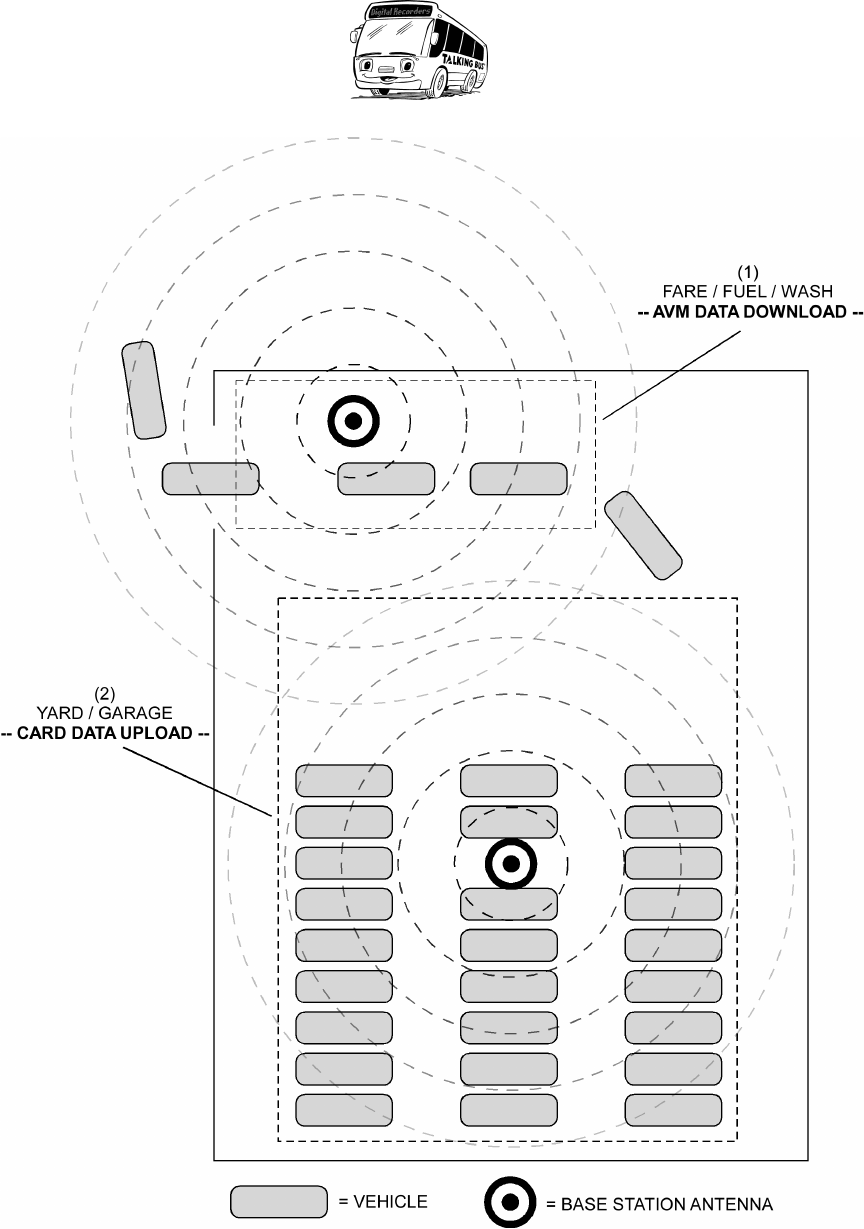
In a typical vehicle yard there is a consistent manner in which the vehicles
arrive for nighttime storage. Each vehicle arrives, one by one, at a fare
collection, refueling, and/or washing station where it is serviced for a
number of minutes. Afterwards, each continues to a yard or garage where
it is parked along side all of the other vehicles and stored for the night.

Wireless Data Transfer SECTION 1
1-2
These two areas (fare/fuel/wash and yard/garage) are typically co-located
and within a few hundred yards of each other.
Depending upon system configuration, the two locations described above
may combine to define a single large wireless transmission area, or
instead be considered two separate communication points, each with a
separate base-station or set of stations.
In the case of data download from the vehicle to the base-station (such as
AVM data), the data will typically be downloaded at the fare/fuel/wash
station area. Where physically possible, the yard/garage storage area may
also be included to enable downloads to continue as the vehicles are
parked. As each vehicle enters the download area, a full duplex
communication link with the base-station is established. Up to four
vehicles may communicate with a single base-station simultaneously and
at full speed. If four vehicles are in the process of downloading data when
additional vehicles enter the area, the entering vehicles are placed in a
queue. Additional base-stations may be added to scale the number of
simultaneous downloads. A day’s worth of AVM data will typically consist
of less than 1MB of data, which should complete in under 5 minutes time
per vehicle.
If uploading of data (such as route changes) to the vehicles is also
configured, then the yard/garage area is defined as a second
communication point. A separate base-station is located in this area and
dedicated to the data upload to vehicles. In the case of a card update, a
large amount of identical information (20+MB) is typically broadcast to
each of the vehicles. This upload is accomplished in a cyclical broadcast
mode, where the data is transmitted repeatedly over the entire night as the
vehicles arrive and are stored, giving each vehicle several opportunities to
acquire the entire message. The onboard vehicle equipment is configured
to remain powered until completing its download, after which it shuts itself
down automatically.
Figure 1 below illustrates the above two wireless locations and the data
transfer that occurs at each.
Wireless Data Transfer SECTION 1
1-3
Figure 1: Typical Wireless Base-station configuration.
Wireless Data Transfer SECTION 2
2-1
COMPONENT LIST & DRAWINGS
2.1 INTRODUCTION
This chapter lists the major components of the Wireless Data Transfer Option,
and contains drawings for the hardware components. In most cases the
equipment will be pre-installed and wired by the vehicle OEM manufacturer, or by
a certified Digital Recorders installation technician.
2.2 COMPONENT LIST
Following is a list of the major components of the Wireless Data Transfer Option.
Complete component list and quantities of each will vary per transit property
dependent upon installation, number of vehicles, number of base-stations, etc.
DR PART # DESCRIPTION
ON VEHICLE
901-1700-000 Module, PX3 with Wireless
941-5220-000 Cable, PX3 To VLU, Comm
801-5207-000 Antenna Assembly, Vehicle
941-5207-020 Cable, Wireless Modem Antenna
BASE-STATION
941-5213-000 RS485 Cable, PX3 to Base-station, Comm
801-5210-000 Antenna Assembly, Base-station
290-0003-000 RS485 Adapter, Comm, Async, 1 Port
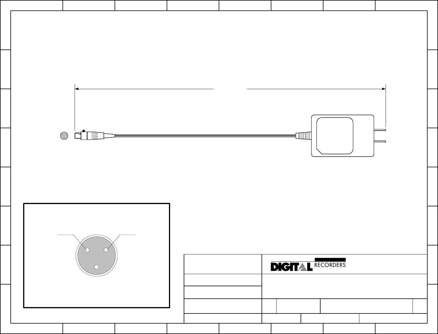
530-0001-024 Power Block, 24VDC, 10W
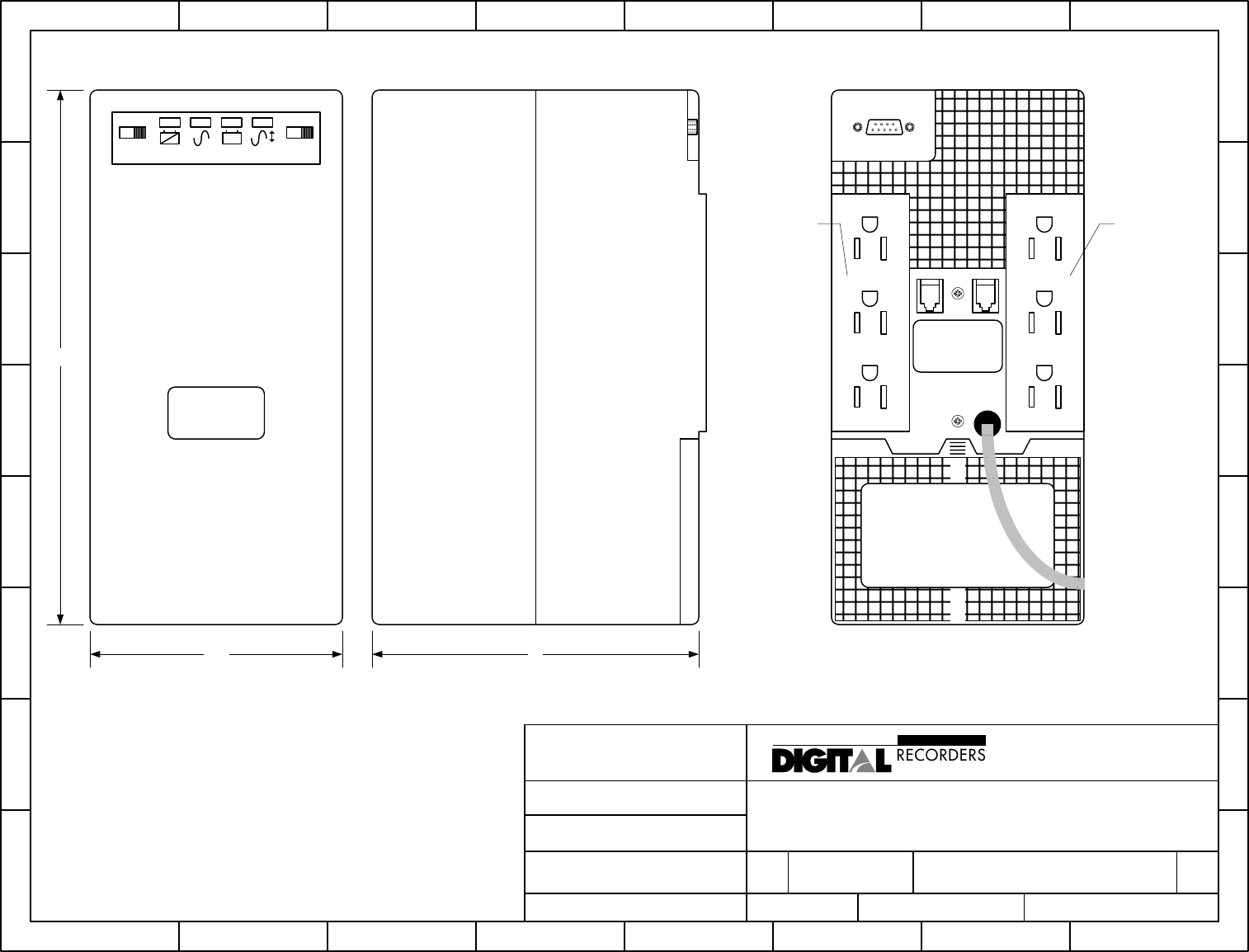
530-0002-700 UPS, Triplite 700VA, Omnismart PNP
575-0002-000 Software, Wireless/AVM Bundle
597-0002-000 Manual, Wireless Data Transfer Option
2.3 COMPONENT DRAWINGS
Following are sample mechanical drawings for the major hardware components
of the Wireless Data Transfer Option. Actual components may vary per transit
property dependent upon installation, etc.
H
G
F
E
D
C
B
A
87654321
H
G
F
E
D
C
B
A
87654321
SIZE PROJECT NO. DWG NO REV
A 1700 AA-901-1700-000 A
SCALE NONE SHEET 1 OF 1
TITLE
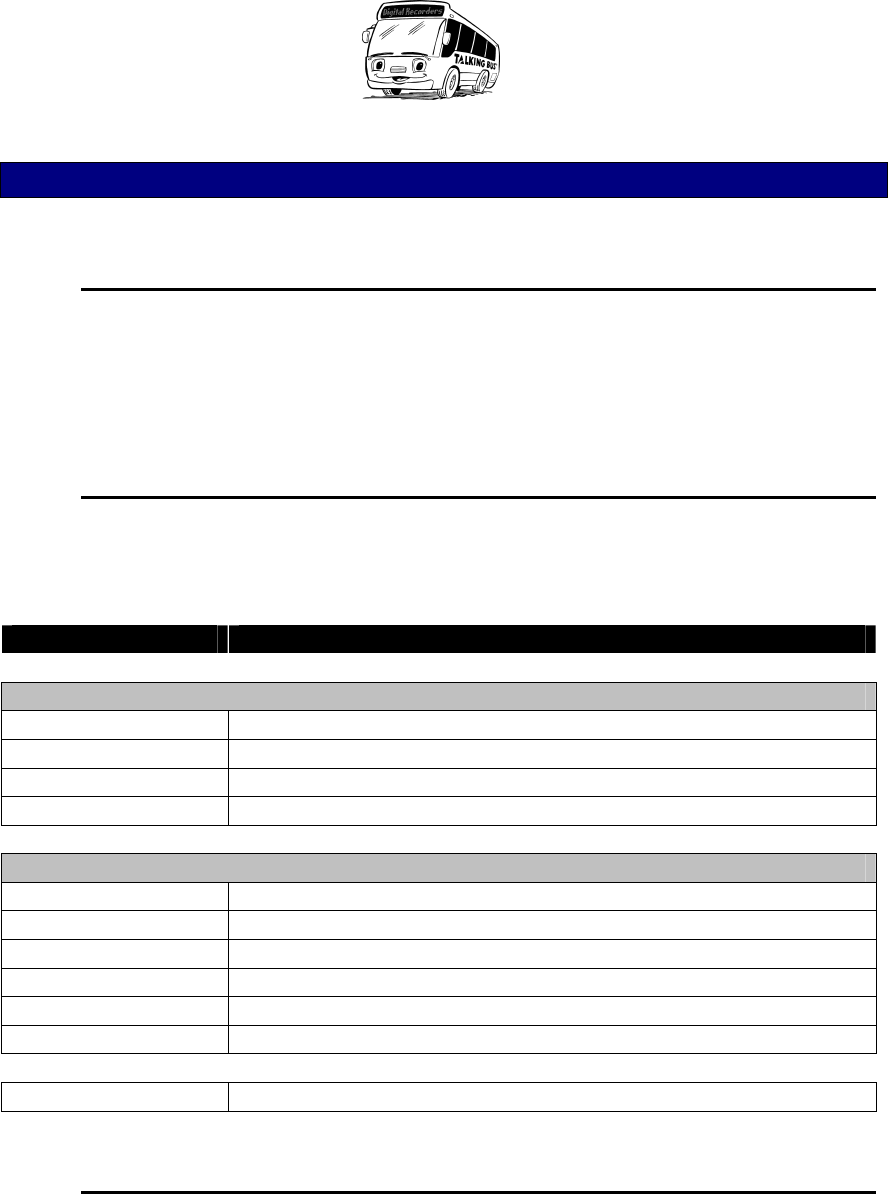
Assembly, PX3/Wireless Modem Module
REVISED
6/4/01
FILENAME
901-1700-000_A.VSD
DRAW N BY JDK
DATE
2/28/00
4900 PROSP ECTUS DR. STE. 1000
P.O. BOX 14068
RESEARCH TRIANGLE PARK, NC 27709-4068 USA
1-800-222-9583 FAX (919)361-2947
Tx
Rx
Status
J3 - POWER
P2 - VLU
P/N 901-1700-000
DIGITAL RECORDERS
PX3 WIRELESS
MODEM MODULE
Range
P3
232/232/PWR/1708
P1
232
DIGITAL RECORDERS
PX3/WIRELESS MODEM 901-1700-000
ANTENNA
5.90
6.83
4.735.11
0.176 x 0.567 SLOT
4 PLACES
APPLY ID LABEL
THIS SIDE
5
5
4
4
3
3
2
2
1
1
D D
C C
B B
A A
SHIELD
SHIELD
DRAIN WIRE
DRAIN WIRE
DRAIN WIRE
DRAIN WIRE
J7
DB9 MALE
J4
DB9 FEMALE
P2
DB15 FEMALE
941-5220-000
REV A (datecode)
DR500C J4
941-5220-000
REV A (datecode)
DR500C J7
941-5220-000
REV A (datecode)
WIRELES P2
SEE BOM # BA-941-5220-000 FOR MATERIAL LIST
CABLE 'A'
CABLE 'A'
CABLE 'B'
CABLE 'B'
OVERALL LENGTH = 22 INCHES +/- 2 INCHES
DIGITAL RECORDERS, A DRI COMPANY
LABEL
LABEL
LABEL
MA-941-5220-000 A
CABLE, PX3-VLU (232/1708)
A
11Monday, March 26, 2001
Title
Size Document Number Rev
Date: Sheet of
DCD
DCD
RXD
RXD
TXD
TXD
DTR
DTR
GND
GND
RTS
RTS
CTS
CTS
RI RI
J1708B J1708B
J1708A
J1708A
P2
DB15 FEMALE
8
15
7
14
6
13
5
12
4
11
3
10
2
9
1
J7
DB9 MALE
5
9
4
8
3
7
2
6
1
J4
DB9 FEMALE
5
9
4
8
3
7
2
6
1
H
G
F
E
D
C
B
A
87654321
H
G
F
E
D
C
B
A
87654321
SIZE PROJECT NO. DWG NO REV
A MA-801-5207-000_C C
SCALE SHEET
1 OF 1
TITLE
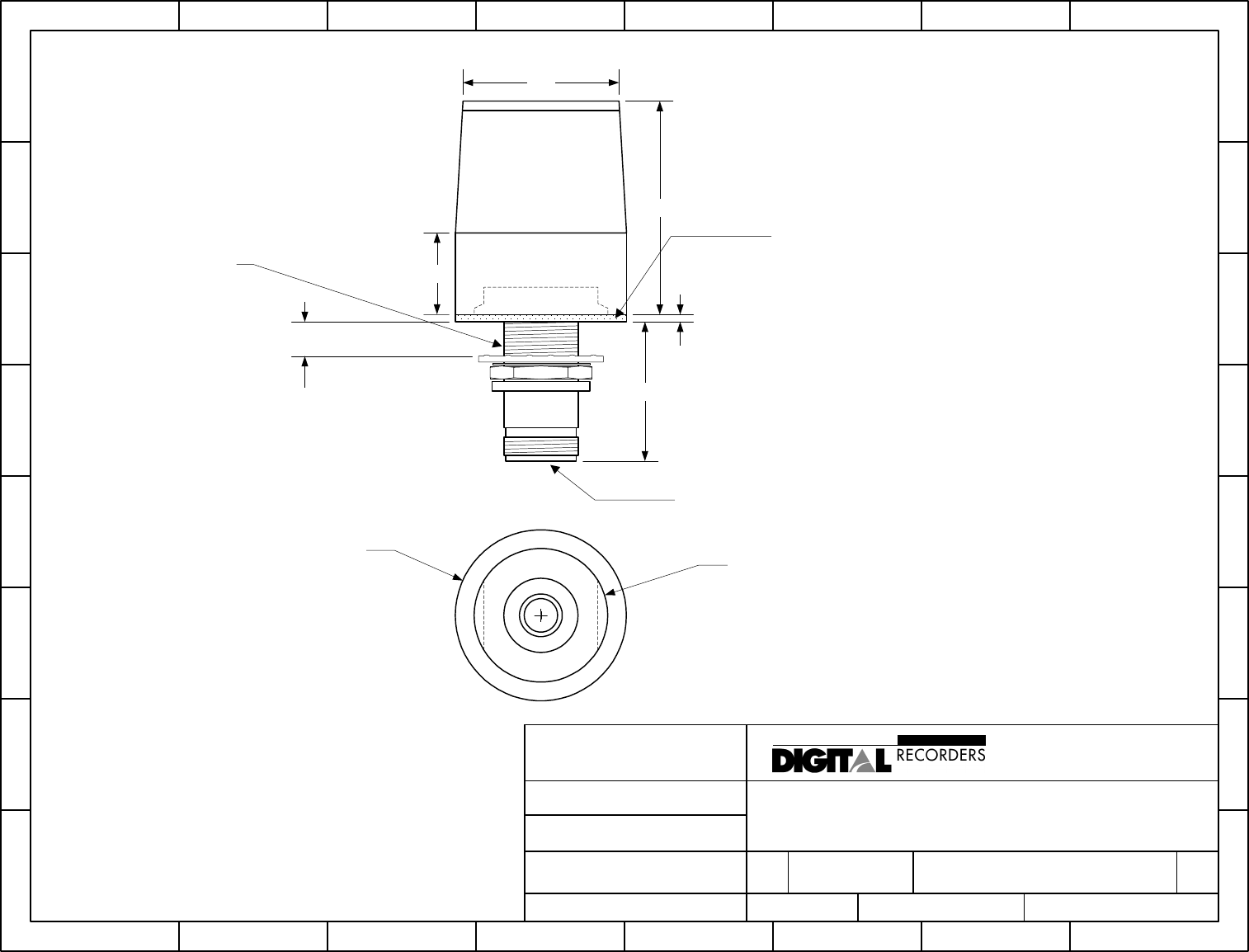
2.4GHZ WIRELESS MODEM ANTENNA
REVISED
3/28/01
FILENAME
MA-801-5207-000_C.VSD
DRAWN BY
SBH
DATE
3/26/01
4018 PATRIOT DRIVE, SUITE 100
P.O. BOX 14068
RESEARCH TRIANGLE PARK, NC 27709 USA
1.800.222.9583 FAX 919.361.2947
www.talkingbus.com
TM
A DRI Company
THIS DRAWING IS THE PROPERTY OF DIGITAL RECORDERS,INC.,
WHO RETAINS ALL PATENT, PROPRIETARY DESIGN, USE, SALE,
AND PRODUCTION RIGHTS. IT MAY NOT BE REPRODUCED OR
USED AS THE BASIS FOR MANUFACTURE OR SALE OF APPARATUS
WITHOUT PERMISSION.
NOTES:
ALL DIMENSIONS IN INCHES
5/8" MOUNTING HOLE REQUIRED
1/2" MAXIMUM MOUNTING THICKNESS
N-TYPE FEMALE JACK CONNECTION
1.80
0.69
1.31
0.06
1.17
0.50 MAX
PLATE THICKNESS
TYPE N FEMALE - JACK
5/8 - 24 UNEF
NEOPRENE WASHER
Ø 1.44
1 1/8 - 18 UNEF EXTERNAL THREAD MOUNT TO ANTENNA BODY
H
G
F
E
D
C
B
A
87654321
H
G
F
E
D
C
B
A
87654321
SIZE PROJECT NO. DWG NO REV
A MA-941-5207-020 C
SCALE
NONE
SHEET
1 OF 1
TITLE
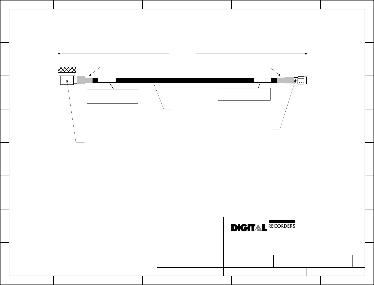
CABLE, ANTENNA, 2.4GHZ, SMA-N, 20 FEET
REVISED
4/5/01
FILENAME
MA-941-5207-020_C.VSD
DRAWN BY
JDK
DATE
4/2/01
4018 PATRIOT DRIVE, SUITE 100
P.O. BOX 14068
RESEARCH TRIANGLE PARK, NC 27709 USA
1.800.222.9583 FAX 919.361.2947
www.talkingbus.com
TM
A DRI Company
THIS DRAWING IS THE PROPERTY OF DIGITAL RECORDERS,INC.,
WHO RETAINS ALL PATENT, PROPRIETARY DESIGN, USE, SALE,
AND PRODUCTION RIGHTS. IT MAY NOT BE REPRODUCED OR
USED AS THE BASIS FOR MANUFACTURE OR SALE OF APPARATUS
WITHOUT PERMISSION.
20 FT +/- 3 IN.
CABLE, COAX
Times Microwave LMR-240
or Approved Equivalent
(O.D. = 0.240 IN)
Plug, Male, SMA
for LMR-240 Cable
To 2.4GHz
Antenna To PX3/Wireless
Modem (DVAS Assy)
LABEL
DRI P/N 941-5207-020
2.4 GHZ ANTENNA
LABEL
Note:
Labels to be positioned within 12"
of cable ends shown (both labels).
Connector, Rt. Angle
Type-N, Male, for
LMR-240 Cable
DRI P/N 941-5207-020
WIRELESS MODEM
Heatshrink tubing Heatshrink tubing
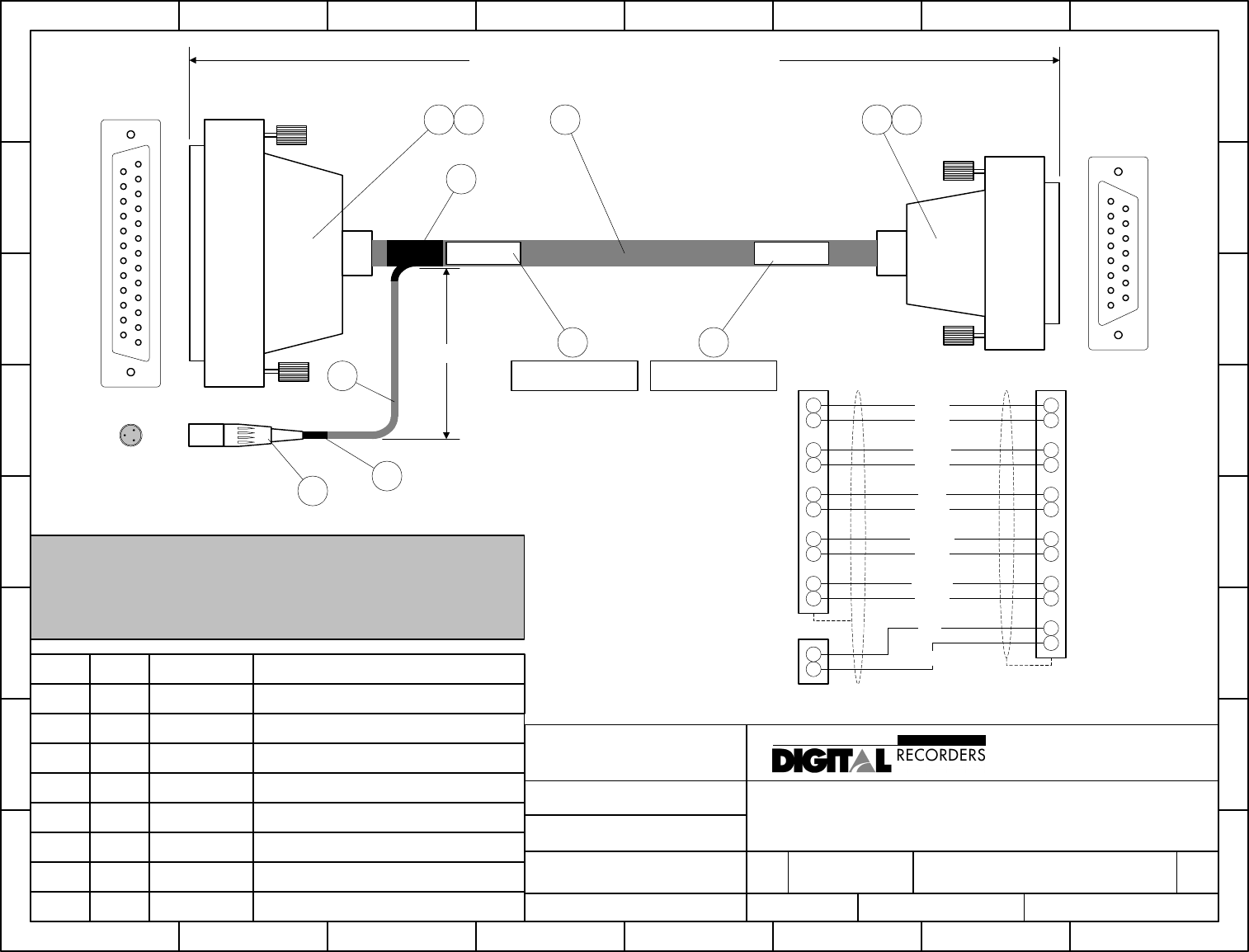
NOTE:
RED/WHITE PAIR TO BE PULLED BACK FROM DB-25 END 6", INSERTED INTO EXPANDABLE TUBING,
AND HEATSHRINK APPLIED AT JUNCTION.
DRAIN WIRE SOLDERED TO DB25, DB15 CONNECTOR SHELLS.
DB-15 CONNECTOR END TO BE ASSEMBLED AT INSTALL LOCATION.
H
G
F
E
D
C
B
A
87654321
H
G
F
E
D
C
B
A
87654321
SIZE PROJECT NO. DWG NO REV
A MA-941-5213-000 A
SCALE
NONE
SHEET
1 OF 1
TITLE
CABLE, DATA+PWR, PX3 MODULE, BASESTATION MODE
REVISED
5/7/01
FILENAME
MA-941-5213-000_A.VSD
DRAWN BY
SBH
DATE
4/2/01
4018 PATRIOT DRIVE, SUITE 100
P.O. BOX 14068
RESEARCH TRIANGLE PARK, NC 27709 USA
1.800.222.9583 FAX 919.361.2947
www.talkingbus.com
TM
A DRI Company
THIS DRAWING IS THE PROPERTY OF DIGITAL RECORDERS,INC.,
WHO RETAINS ALL PATENT, PROPRIETARY DESIGN, USE, SALE,
AND PRODUCTION RIGHTS. IT MAY NOT BE REPRODUCED OR
USED AS THE BASIS FOR MANUFACTURE OR SALE OF APPARATUS
WITHOUT PERMISSION.
Rx+
Rx-
CTS+
CTS-
Tx+
Tx-
RTS+
RTS-
DTR+
DTR-
+24VDC
GND
WHITE
BLACK
GREEN
BLACK
BLUE
BLACK
YELLOW
BLACK
BROWN
BLACK20
23
4
19
2
14
5
13
3
16
15
8
11
3
12
4
10
2
9
1
BLACK
5
3
RED
SHIELD
SHIELD 13
1
DB25
(RS-422 CARD)
DB15
(PX3 P2 CONN.)
SWITCHCRAFT
(POWER SUPPLY)
DB25
FEMALE
DB15
FEMALE
SWITCHCRAFT
3-POS. MALE
8 2 B292 BRADY: REFERENCE ID LABEL
6 1 TA3M SWITCHCRAFT: 3 POS. MALE CON.
5 2 1-747579-1 AMP: STEPPED FERRULE (.324-.375)
ITEM QTY. MFG. PART # MFG: DESCRIPTION
4 1 748049-1 AMP: HD-20 DB15 FEMALE CON. KIT
3 1 748051-1 AMP: HD-20 DB25 FEMALE CON. KIT
1 TBD 6377 ALPHA: 6 PAIR, FOIL/BRAID (22 AWG)
LENGTH TO BE DETERMINED AT INSTALLATION
6 +/-1 IN.
3 1 4 55
6
LABEL LABEL
88
7 N/A N/A HEATSHRINK TUBING
2 6" GRP-110NF14 ALPHA: .25" DIA. EXPANDABLE TUBING
2
7
7
DRI P/N 941-5213-000
BASESTATION PC
DRI P/N 941-5213-000
BASESTATION MODEM
H
G
F
E
D
C
B
A
87654321
H
G
F
E
D
C
B
A
87654321
SIZE PROJECT NO. DWG NO REV
A MA-290-0003-000_A A
SCALE SHEET
1 OF 1
TITLE
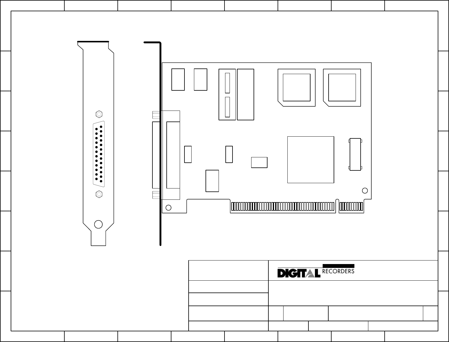
RS485 ADAPTER, COMM, ASYNC, 1 PORT
REVISED
5/24/01
FILENAME
MA-290-0003-000_A.VSD
DRAWN BY
SBH
DATE
5/24/01
4018 PATRIOT DRIVE, SUITE 100
P.O. BOX 14068
RESEARCH TRIANGLE PARK, NC 27709 USA
1.800.222.9583 FAX 919.361.2947
www.talkingbus.com
TM
A DRI Company
THIS DRAWING IS THE PROPERTY OF DIGITAL RECORDERS,INC.,
WHO RETAINS ALL PATENT, PROPRIETARY DESIGN, USE, SALE,
AND PRODUCTION RIGHTS. IT MAY NOT BE REPRODUCED OR
USED AS THE BASIS FOR MANUFACTURE OR SALE OF APPARATUS
WITHOUT PERMISSION.
H
G
F
E
D
C
B
A
87654321
H
G
F
E
D
C
B
A
87654321
SIZE PROJECT NO. DWG NO REV
A MA-530-0001-024 A
SCALE SHEET
1 OF 1
TITLE
POWER SUPPLY, PX3, BASESTATION MODE
REVISED
6/1/01
FILENAME
MA-530-0001-024_A.VSD
DRAWN BY
SBH
DATE
4/30/01
4018 PATRIOT DRIVE, SUITE 100
P.O. BOX 14068
RESEARCH TRIANGLE PARK, NC 27709 USA
1.800.222.9583 FAX 919.361.2947
www.talkingbus.com
TM
A DRI Company
THIS DRAWING IS THE PROPERTY OF DIGITAL RECORDERS,INC.,
WHO RETAINS ALL PATENT, PROPRIETARY DESIGN, USE, SALE,
AND PRODUCTION RIGHTS. IT MAY NOT BE REPRODUCED OR
USED AS THE BASIS FOR MANUFACTURE OR SALE OF APPARATUS
WITHOUT PERMISSION.
APPROX. 6 FT.
13
2
+24VDC
(BLK/WHT)
GROUND
(BLK)
CONNECTOR DETAIL
(SWITCHCRAFT TA3F)
DC POWER OUT
(+24VDC)
AC POWER IN
(120/240VAC, 60/50Hz)
H
G
F
E
D
C
B
A
87654321
H
G
F
E
D
C
B
A
87654321
SIZE PROJECT NO. DWG NO REV
A 530-0002-700 A
SCALE SHEET
1 OF 1
TITLE
UPS, TRIPLITE 700VA, OMNISMART PNP
REVISED
5/25/01
FILENAME
MA-530-0002-700_A.VSD
DRAWN BY
SBH
DATE
5/24/01
4018 PATRIOT DRIVE, SUITE 100
P.O. BOX 14068
RESEARCH TRIANGLE PARK, NC 27709 USA
1.800.222.9583 FAX 919.361.2947
www.talkingbus.com
TM
A DRI Company
THIS DRAWING IS THE PROPERTY OF DIGITAL RECORDERS,INC.,
WHO RETAINS ALL PATENT, PROPRIETARY DESIGN, USE, SALE,
AND PRODUCTION RIGHTS. IT MAY NOT BE REPRODUCED OR
USED AS THE BASIS FOR MANUFACTURE OR SALE OF APPARATUS
WITHOUT PERMISSION.
+-+-
OFF ON MUTE / TEST
SURGE
PROTECTION
AND UPS
BATTERY
BACKUP
SURGE
PROTECTION
ONLY
10.5"
4.5" 7"
FRONT SIDE REAR
DR500C+
VLU
J5/RS232B
J4/RS232A PX3/Wireless
Modem Module
J7/J1708C
J9/RS485D Fanout Cable, J1708
Int.
Sign
Twin Vision
IO Controls
Gateway
Module
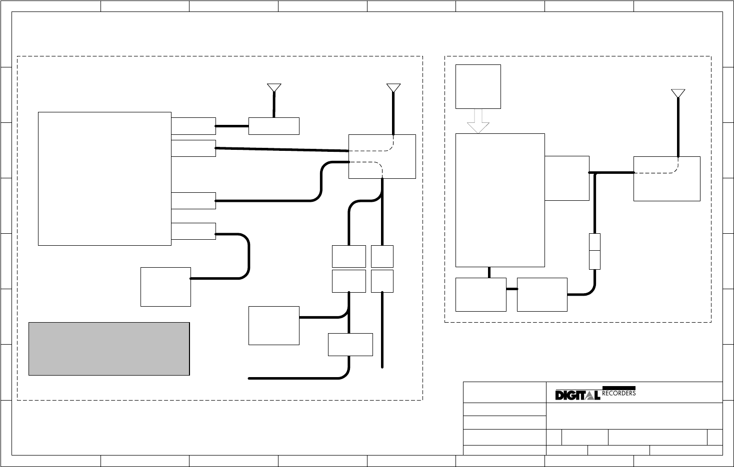
SAMPLE SYSTEM ARCHITECTURE
PX3 MODULE, VIA EXTERNAL RELAY (NOT
SHOWN) CONTROLS POWER TO VLU, GPS,
AND K-60 OCU.
On-vehicle
Equipment
PX3/Wireless
Modem Module
RS485
Comm
Adapter
(PCI)
Base
Station
Software
24VDC
Power Block
Base Station
Equipment
H
G
F
E
D
C
B
A
87654321
H
G
F
E
D
C
B
A
87654321
SIZE PROJECT NO. DWG NO REV
A None
SCALE SHEET 1 OF 1
TITLE
WIRELESS TRANSFER OPTION SYSTEM ARCHITECTURE
REVISED
6/4/01
FILENAME
SYSTEM ARCHITECTURE.VSD
DRAW N BY
JDK
DATE
4/24/01
4018 PATRIOT DRIVE, SUITE 100
P.O. BOX 14068
RESEARCH TRIANGLE PARK, NC 27709 USA
1.800.222.9583 FAX 919.361.2947
www.talkingbus .com
TM A DR I C o mp a ny
THIS DRAWING IS THE PROPERTY OF DIGITAL RECORDERS,INC.,
WHO RETAINS ALL PATENT, PROPRI ETARY DESIGN, USE, SALE,
AND PRODUCTION RIGHTS. IT MAY NOT BE REPRODUCED OR
USED AS THE BASIS FOR MANUFACTURE OR SALE O F APPARATUS
WITHOUT PERMISSION.
UPS
Windows
PC with
PCI slots
GPS
Base Station
Antenna Assembly
Vehicle Wireless
Antenna Assembly
GPS Antenna
M
F
Switchcraft TA3
connectors
OCU
LT-2
OCU
K-60
Panel-Mt

Wireless Data Transfer SECTION 3
3-1
COMPONENT CONNECTIONS
3.1 INTRODUCTION
This chapter describes the major component connections of the Wireless Data
Transfer Option.
NOTE: The equipment comprising your Wireless Transfer Option should have
been pre-installed by the OEM vehicle manufacturer and/or by Digital
Recorders certified installation technicians. Installation may vary
significantly from one location to another. The following instructions are
therefore basic in nature and designed only to assist in understanding
the system or for individual component replacement.
WARNING: Changes or modifications not expressly approved by
Digital Recorders, Inc. may void the user’s authority to
operate this equipment.
3.2 ON-VEHICLE EQUIPMENT
The Wireless Data Transfer Option on-vehicle equipment includes the following
five basic components:
1. Wireless Modem Module
2. Power harness
3. Data communications cable
4. Antenna cable
5. Antenna assembly
Note that item 2, power harness, is potentially different for each installation and is
therefore is not described in detail in this manual.
The Wireless Modem Module (DR P/N 901-1700-000) is an enclosure which
houses a wireless modem, controlling electronics, and expanded serial ports for
the DR500C. It also ‘fans out’ (duplicates) the DR500C J1708 communication
port. Typically the module will be found mounted on a plate along with the
DR500C and other supporting electronics.

Wireless Data Transfer SECTION 3
3-2
The modem module is powered by a power harness (unique to each installation)
via the 9-pin CPC connection J3. This connection also provides relay control to
automatically shutdown power to the DR500C once data transfer has completed.
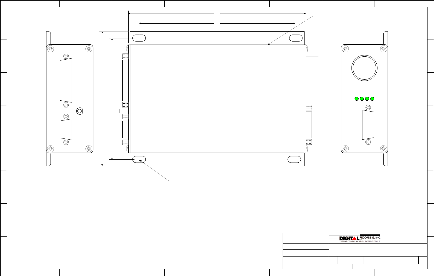
Serial communication between the modem module and the DR500C is
performed via a data cable (DR P/N 941-5220-000). The DB-15 end of this cable
connects to the modem module port P2. The other end of the cable has two
connections: the DB-9 female is for RS232 communications and connects to the
DR500C port A (J4), while the DB-9 Male is for J1708 ‘fan out’ and connects to
the DR500C port C (J7). Thumbscrews for each connector should be securely
fastened.
The antenna cable (DR P/N 941-5207-020) is connected to the wireless modem
module via its SMA connection marked “Antenna”. The SMA connector should be
screwed on clockwise and firmly hand-tightened
The vehicle antenna assembly (DR P/N 801-5207-000) is typically mounted on
the roof above the driver’s area of the vehicle via a 5/8” mounting hole. The
antenna assembly terminates within the interior of the vehicle with a Type-N
connector, to which the right-angle mating end of the antenna cable is connected
and firmly hand-tightened in a clockwise fashion.
WARNING: To satisfy FCC RF exposure requirements for mobile
transmitting devices, a separation distance of 32cm or
more should be maintained between the antenna of this
device and persons during device operation. To ensure
compliance, operations at closer than this distance is not
recommended.

Wireless Data Transfer SECTION 3
3-3
3.3 BASE-STATION EQUIPMENT
The Wireless Data Transfer Option base-station equipment includes the following
eight basic components:
1. Wireless Modem Module
2. Antenna cable
3. Base-station antenna assembly
4. RS485 communications / power cable
5. RS485 PCI adapter
6. 24VDC power supply
7. Uninterruptible Power Supply (UPS)
8. PC with software
The wireless modem module and antenna cable are identical to those which are
used on the vehicle and described in the previous section. The antenna cable is
connected to the module via a SMA connector. The other end of the antenna
cable is connected to the Base-station antenna assembly via Type-N connector.
The base-station antenna, antenna cable, and modem module are mounted in a
location which provides the best “top-down” line-of-sight view of the vehicles
within its intended zone of communication. Base-station antenna type will vary
per installation depending upon mounting location and coverage pattern
requirements. Typical mounting locations include the roof of a building, a well-
positioned wall, a tall pole, or the center ceiling of a covered garage area. The
antenna must be securely fastened, and if in an outside location it must be
properly grounded for lightning strike protection.
WARNING: To satisfy FCC RF exposure requirements for mobile
transmitting devices, a separation distance of 32cm or
more should be maintained between the antenna of this
device and persons during device operation. To ensure
compliance, operations at closer than this distance is not
recommended.
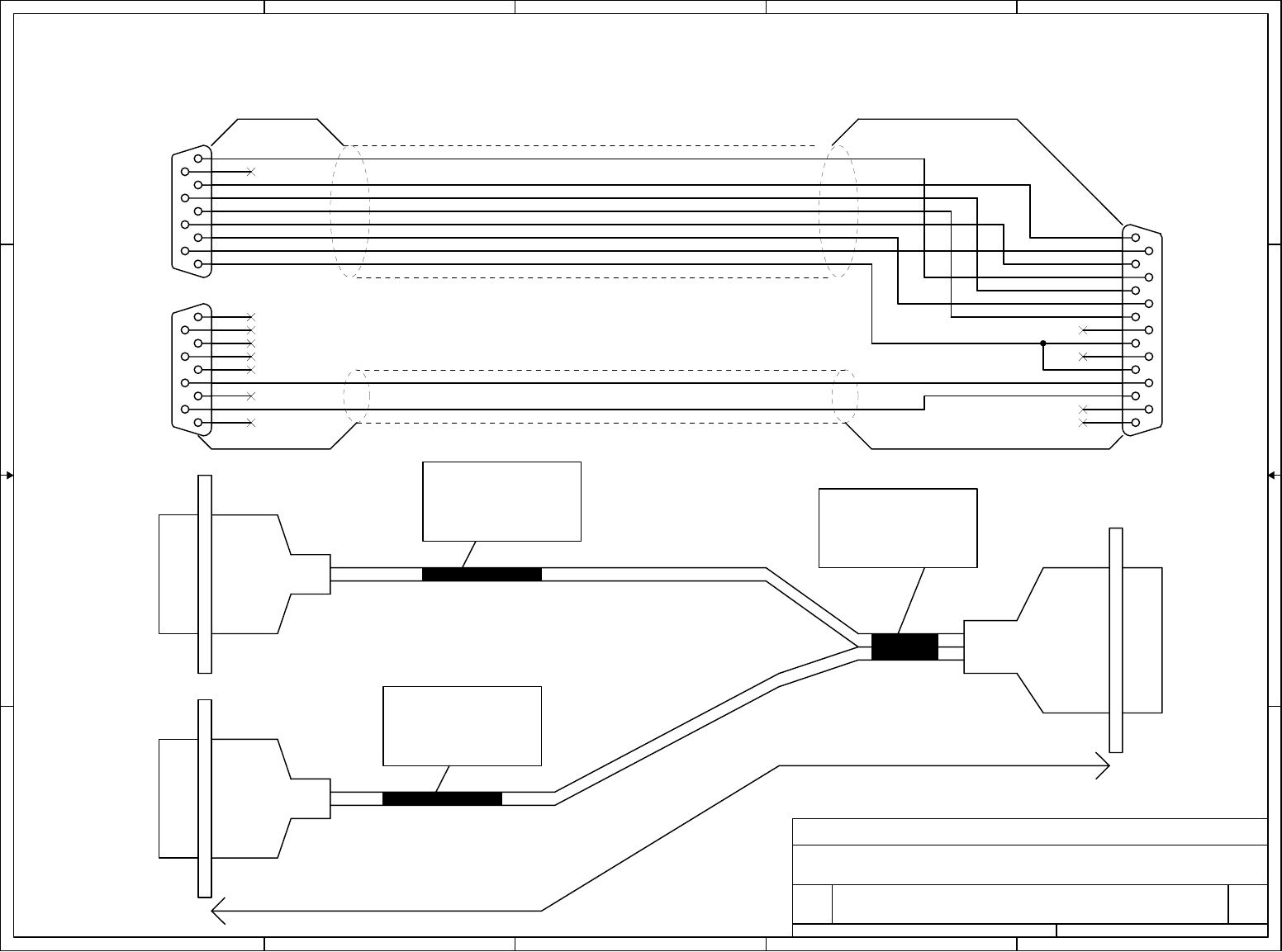
Communication from the base-station PC and DC power are delivered via the
RS485 cable (DR P/N 941-5213). This cable is built to length for each
installation, and can be run up to 1000 feet without compromising data integrity.
Depending upon installation location, this cable may be routed through conduit,
underground, etc. The cable connects to the Wireless Modem Module port P2 via

Wireless Data Transfer SECTION 3
3-4
its male DB-15 connector, and terminates at the base-station PC end in a male
DB-25 connector (data) and male Switchcraft “TA3M” connector (power).
The base-station PC contains a 485 PCI communications card (DR P/N 290-
0003-000), to which the male DB-25 data connector of the RS485 cable is
connected. Both thumbscrews on the connector should be hand tightened.
A small wall “plug-style” 24VDC power block (DR P/N 530-0001-024) supplies
DC power to the modem module. It connects to the RS485 cable at the base-
station PC end via its female Switchcraft “TA3F” connector. Press down on the
top-mounted button to disconnect, and push the two ends together until a “click”
is heard to re-connect.
Both the 24VDC power block and the base-station PC should be plugged into the
700VA UPS (DR P/N 530-0002-700), which in turn plugs into a standard 120VAC
outlet. The UPS (Uninterruptible Power Supply) provides battery backup during
short (<15 minute) AC power outages, spikes, or “brownouts”. This ensures that
such occurrences will not affect communication with the vehicles. Both the PC
and the power block must be plugged into the UPS outlets labeled
“BATTERY/SURGE & NOISE PROTECTED OUTLETS’ (right side outlets as
viewed from the rear) to be protected from full power outages. Digital Recorders
suggests plugging the PC monitor and other peripherals into the left side outlets,
which are only surge protected, to maximize battery backup time of the PC and
modem during complete power failures.
Wireless Data Transfer SECTION 4
4-1
CHECKOUT PROCEDURE
4.1 INTRODUCTION
This chapter contains a basic checkout procedure for the vehicle mounted
wireless equipment. For checkout information regarding the base-station
equipment, please refer to its separate documentation.
4.2 VEHICLE MOUNTED EQUIPMENT CHECKOUT
To confirm operation of the vehicle mounted equipment, perform the following:
1. Turn on vehicle and wait for ‘Talking Bus’ equipment to boot (OCU will
prompt for route login).
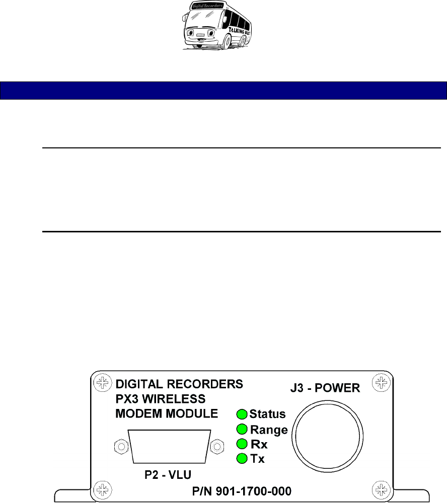
2. Observe the front panel of the wireless modem module. A vertical row of
four LED’s is located on this panel. The LED’s are, from top to bottom,
“Status”, “Range”, “Rx”, Tx”.
Figure 2: Wireless Modem Module Front Panel
3. The “Status” LED will flash when power is applied to the unit and it is
functioning properly. If solidly lit or unlit, disconnect the J3 power
connector, wait five seconds, then reconnect. If the LED still does not
blink, contact Digital Recorders for further testing instructions.
4. If the vehicle is within communication range of the base-station, the
“Range” LED should be lit. If not lit, first check that the vehicle is well
within the receiving range of the base-station antenna (typically <1000
feet, without major structures between). Second, check that the antenna
cable is firmly attached to the back of the unit. Third, ensure that the

Wireless Data Transfer SECTION 4
4-2
opposite end of the cable is firmly attached to the antenna assembly
mounted on the roof of the vehicle. Lastly, verify that the base-station and
related software are powered and running correctly.
5. The Rx and Tx LED’s will flash to indicate data being received or
transmitted, respectively.
For further information or troubleshooting assistance, please contact Digital
Recorders technical support at:
1 – 800 – 222 – 9583
Mon. – Fri. 8:30am – 5:30pm EST