02 – Build & Installation Guide Type 2 V0.6
User Manual:
Open the PDF directly: View PDF ![]() .
.
Page Count: 82
Type 2 Liverpool
Ringing Simulator
02 – Build & Installation Guide
Author: Andrew Instone-Cowie
Date: 10 February 2019
Version: Draft 0.6

Type 2 Simulator – Build & Installation Guide 0.6
2
Contents
Index of Figures ....................................................................................................................................... 4
Index of Tables ........................................................................................................................................ 7
Document History ................................................................................................................................... 8
Licence .................................................................................................................................................... 9
Documentation Map ............................................................................................................................. 10
About This Guide ................................................................................................................................... 11
Typical Simulator Installation ................................................................................................................ 12
What You Will Need .............................................................................................................................. 13
Skills .................................................................................................................................................. 13
Tools .................................................................................................................................................. 13
Parts .................................................................................................................................................. 13
PCBs................................................................................................................................................... 14
OSH Park ....................................................................................................................................... 14
SeeedStudio .................................................................................................................................. 14
Simulator Assembly .............................................................................................................................. 17
Polarised Components ...................................................................................................................... 17
Voltage Regulators ........................................................................................................................ 17
Diodes ........................................................................................................................................... 18
Electrolytic Capacitors ................................................................................................................... 18
Integrated Circuits ......................................................................................................................... 19
LEDs ............................................................................................................................................... 19
Magneto-Resistive Sensors ........................................................................................................... 20
Simulator Interface Board ................................................................................................................. 21
Parts List ........................................................................................................................................ 21
Schematic ...................................................................................................................................... 22
Parts .............................................................................................................................................. 23
PCB Layout .................................................................................................................................... 23
Construction .................................................................................................................................. 24
Voltage Regulator ......................................................................................................................... 25
Power Board ..................................................................................................................................... 28
Parts List ........................................................................................................................................ 28
Schematic ...................................................................................................................................... 29

Type 2 Simulator – Build & Installation Guide 0.6
3
Parts .............................................................................................................................................. 30
PCB Layout .................................................................................................................................... 30
Construction .................................................................................................................................. 30
Magneto-Resistive Sensor ................................................................................................................ 32
Parts List ........................................................................................................................................ 32
Schematic ...................................................................................................................................... 33
Parts .............................................................................................................................................. 34
PCB Layout .................................................................................................................................... 34
Construction .................................................................................................................................. 34
Infra-Red & Other Sensors ................................................................................................................ 36
Parts List ........................................................................................................................................ 36
Schematic ...................................................................................................................................... 37
PCB Layout .................................................................................................................................... 38
Construction .................................................................................................................................. 38
Infra-Red Sensor............................................................................................................................ 40
Enclosures ......................................................................................................................................... 41
Parts List ........................................................................................................................................ 41
Simulator Interface & Power Boards Enclosure ............................................................................ 42
Magneto-Resistive Sensors Enclosure .......................................................................................... 42
Infra-Red Sensors Enclosure ......................................................................................................... 43
Grommets ..................................................................................................................................... 43
Completed Assemblies ...................................................................................................................... 45
Simulator Interface ....................................................................................................................... 45
Power Board.................................................................................................................................. 45
Magneto-Resistive Sensor ............................................................................................................ 46
Infra-Red Sensor............................................................................................................................ 46
Firmware Upload .................................................................................................................................. 47
Hardware Programmer Options ....................................................................................................... 48
Preparing the Environment ............................................................................................................... 49
Preparing the Programmer ............................................................................................................... 52
Setting the Fuses ............................................................................................................................... 56
Firmware Upload .............................................................................................................................. 60
Simulator Installation ............................................................................................................................ 63
Simulator Interface ........................................................................................................................... 63

Type 2 Simulator – Build & Installation Guide 0.6
4
Power Board ..................................................................................................................................... 64
Power Supply ................................................................................................................................ 64
Sensor Mounting ............................................................................................................................... 64
Magnet Mounting ............................................................................................................................. 66
Infra-Red Sensors .............................................................................................................................. 68
Reflector ........................................................................................................................................ 68
Calibration ..................................................................................................................................... 68
Cabling............................................................................................................................................... 69
Power/Data Cable ......................................................................................................................... 69
Sensor Cables ................................................................................................................................ 69
Computer Connection ................................................................................................................... 70
Interface Setup ...................................................................................................................................... 72
Connecting to the Interface .............................................................................................................. 72
Worked Example ............................................................................................................................... 73
Sensor Channels ............................................................................................................................ 73
Example Installation ...................................................................................................................... 75
Default Settings ............................................................................................................................. 76
Disable Unused Channels .............................................................................................................. 77
Re-Map Channels to Bells ............................................................................................................. 78
Save Settings ................................................................................................................................. 79
Next Steps ............................................................................................................................................. 80
Licensing & Disclaimers ......................................................................................................................... 81
Documentation ................................................................................................................................. 81
Software ............................................................................................................................................ 81
Acknowledgements ............................................................................................................................... 82
Index of Figures
Figure 1 – Documentation Map ............................................................................................................ 10
Figure 2 – Simulator General Arrangement .......................................................................................... 12
Figure 3 – PCB Panels of Sensor Boards ................................................................................................ 15
Figure 4 – SeeedStudio Upload Box ...................................................................................................... 15
Figure 5 – SeeedStudio Gerber Viewer ................................................................................................. 15
Figure 6 – SeeedStudio Order Form ...................................................................................................... 16

Type 2 Simulator – Build & Installation Guide 0.6
5
Figure 7 – Voltage Regulator Orientation ............................................................................................. 17
Figure 8 – Diode Orientation ................................................................................................................ 18
Figure 9 – Electrolytic Capacitor Orientation ........................................................................................ 18
Figure 10 – Integrated Circuit Orientation ............................................................................................ 19
Figure 11 – LED Orientation .................................................................................................................. 19
Figure 12 – Magneto-Resistive Sensor Orientation .............................................................................. 20
Figure 13 – Simulator Interface Parts ................................................................................................... 23
Figure 14 – Simulator Interface Board Layout ...................................................................................... 23
Figure 15 – Voltage Check Pin Locations .............................................................................................. 25
Figure 15 – Bending Voltage Regulator Pins ......................................................................................... 26
Figure 16 – Voltage Regulator Heatsink ................................................................................................ 26
Figure 17 – Completed Simulator Interface PCB .................................................................................. 27
Figure 18 – Power Board Parts.............................................................................................................. 30
Figure 19 – Power Board Layout ........................................................................................................... 30
Figure 20 – Completed Power Board PCB ............................................................................................. 31
Figure 21 – Magneto-Resistive Sensor Demonstration ........................................................................ 32
Figure 22 – Magneto-Resistive Sensor Board Parts .............................................................................. 34
Figure 23 – Magneto-Resistive Sensor Board Layout ........................................................................... 34
Figure 24 – Completed Magneto-Resistive Sensor PCB (Right-Handed) .............................................. 35
Figure 25 – Magneto-Resistive Sensor Board Layout ........................................................................... 38
Figure 26 – Completed Generic Sensor PCB ......................................................................................... 39
Figure 27 – Infra-Red Sensor Wiring ..................................................................................................... 40
Figure 28 – Simulator Interface & Power Board Enclosure Drilling Guide ........................................... 42
Figure 29 – Magneto-Resistive Sensor Enclosure Drilling Guide .......................................................... 42
Figure 30 – Infra-Red Sensor Enclosure Drilling Guide ......................................................................... 43
Figure 31 – Grommets Drilled & Cut ..................................................................................................... 44
Figure 32 – Completed Sensor Interface .............................................................................................. 45
Figure 33 – Completed Power Board .................................................................................................... 45
Figure 34 – Completed Magneto-Resistive Sensor ............................................................................... 46
Figure 35 – Completed Infra-Red Sensor .............................................................................................. 46
Figure 36 – Hardware Programmers ..................................................................................................... 48
Figure 37 – Arduino IDE Preferences Menu .......................................................................................... 49
Figure 38 – Arduino IDE Sketchbook Location ...................................................................................... 50
Figure 39 – Arduino IDE Boards Manager Menu .................................................................................. 51

Type 2 Simulator – Build & Installation Guide 0.6
6
Figure 40 – Arduino IDE Board Manager .............................................................................................. 52
Figure 41 – Arduino USB Cable ............................................................................................................. 52
Figure 42 – Arduino IDE ISP Sketch Loading ......................................................................................... 53
Figure 43 – Arduino Programmer Board Selection ............................................................................... 54
Figure 44 – Arduino Programmer Port Selection .................................................................................. 54
Figure 45 – Arduino IDE ISP Upload ...................................................................................................... 55
Figure 46 – Programmer with Capacitor ............................................................................................... 56
Figure 47 – Programmer Connections .................................................................................................. 56
Figure 48 – Programmer Connected to Interface Board ...................................................................... 57
Figure 49 – Arduino IDE Target Board Selection ................................................................................... 58
Figure 50 – Arduino IDE Programmer Selection ................................................................................... 59
Figure 51 – Arduino IDE Burn Bootloader ............................................................................................. 60
Figure 52 – Arduino IDE Add Library ..................................................................................................... 61
Figure 53 – Arduino IDE Firmware Upload ........................................................................................... 62
Figure 54 – Installed Simulator Interface .............................................................................................. 63
Figure 55 – Installed Sensor (Lois Weedon 4th) ..................................................................................... 64
Figure 56 – Installed Sensor (Lois Weedon 6th) ..................................................................................... 65
Figure 57 – Installed Sensor (Chirk) ...................................................................................................... 65
Figure 58 – Magnet Mounting Dimensions .......................................................................................... 66
Figure 59 – Magnet Mounting Construction ........................................................................................ 67
Figure 60 – Completed Magnet Mounting ........................................................................................... 67
Figure 61 – Sensor Daisy Chain ............................................................................................................. 69
Figure 62 – 9-Pin Serial Port .................................................................................................................. 70
Figure 63 – 9-Pin Serial Cable................................................................................................................ 70
Figure 64 – PC USB Ports ....................................................................................................................... 71
Figure 65 – USB to Serial Adapter ......................................................................................................... 71
Figure 66 – PuTTY Configuration Dialogue ........................................................................................... 72
Figure 67 – Display Interface Settings ................................................................................................... 73
Figure 68 – Interface Channel Numbers ............................................................................................... 74
Figure 69 – Example Sensor Cabling ..................................................................................................... 75
Figure 70 – Example Channel Connections ........................................................................................... 75
Figure 71 – Disabled Channels .............................................................................................................. 76
Figure 72 – Default Settings .................................................................................................................. 76
Figure 73 – Disabling Channels Example ............................................................................................... 77

Type 2 Simulator – Build & Installation Guide 0.6
7
Figure 74 – Channel Re-Mapping Example ........................................................................................... 79
Figure 75 – Example Channel Connections ........................................................................................... 79
Figure 76 – Saving Interface Settings .................................................................................................... 80
Index of Tables
Table 1 – OSH Park Permalinks ............................................................................................................. 14
Table 2 – Simulator Interface Board Parts List ...................................................................................... 21
Table 3 – Power Board PCB Parts List ................................................................................................... 28
Table 4 – Magneto-Resistive Sensor Board Parts List ........................................................................... 32
Table 5 – Generic Sensor Board Parts List ............................................................................................ 36
Table 6 – Enclosures Parts List .............................................................................................................. 41
Table 7 – Example Channel Mapping .................................................................................................... 78
Table 8 – Bell Numbers & Letters ......................................................................................................... 78

Type 2 Simulator – Build & Installation Guide 0.6
8
Document History
Version
Author
Date
Changes
0.1
A J Instone-Cowie
10/09/2018
First Draft.
0.2
A J Instone-Cowie
27/10/2018
Minor corrections, PCB ordering, voltage regulator.
0.3
A J Instone-Cowie
02/11/2018
Changed Farnell 1N4001 part code for a more
available UK stocked item.
0.4
A J Instone-Cowie
24/01/2019
Minor corrections, updated interface PCB to Rev D,
added guidance on polarised components.
0.5
A J Instone-Cowie
05/02/2019
Replaced Amphenol RJHSE-5080-02 (no longer
stocked by Farnell) with AMP TE Connectivity
5406526-1.
Remove references to the Boardstuff programming
shield, which is no longer available, and replace with
examples of generic hardware programmers.
0.5
A J Instone-Cowie
10/02/2019
Add diagram identifying pins for voltage checks.
Add link to GitHub repository Issues log.
Copyright ©2018-19 Andrew Instone-Cowie.
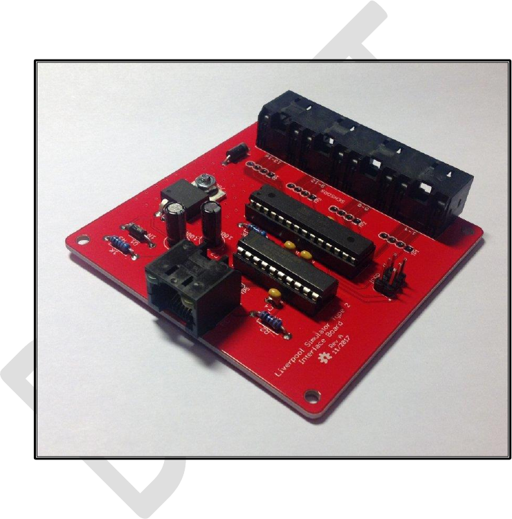
Cover photograph: A completed Type 2 Simulator Interface Board.
PC ports vector graphic design by https://www.vecteezy.com
(Vecteezy Standard Licence, Free for personal and commercial use with attribution.)

Type 2 Simulator – Build & Installation Guide 0.6
9
Licence
This work is licensed under a Creative Commons Attribution-ShareAlike 4.0 International License.
1
Unless otherwise separately undertaken by the Licensor, to the extent possible, the Licensor offers
the Licensed Material as-is and as-available, and makes no representations or warranties of any kind
concerning the Licensed Material, whether express, implied, statutory, or other. This includes,
without limitation, warranties of title, merchantability, fitness for a particular purpose, non-
infringement, absence of latent or other defects, accuracy, or the presence or absence of errors,
whether or not known or discoverable. Where disclaimers of warranties are not allowed in full or in
part, this disclaimer may not apply to You.
To the extent possible, in no event will the Licensor be liable to You on any legal theory (including,
without limitation, negligence) or otherwise for any direct, special, indirect, incidental, consequential,
punitive, exemplary, or other losses, costs, expenses, or damages arising out of this Public License or
use of the Licensed Material, even if the Licensor has been advised of the possibility of such losses,
costs, expenses, or damages. Where a limitation of liability is not allowed in full or in part, this
limitation may not apply to You.
1
http://creativecommons.org/licenses/by-sa/4.0/

Type 2 Simulator – Build & Installation Guide 0.6
10
Documentation Map
Figure 1 – Documentation Map

Type 2 Simulator – Build & Installation Guide 0.6
11
About This Guide
The Type 2 Liverpool Ringing Simulator allows sensors, attached to one or more real tower bells or
teaching dumb bells, to be connected to a computer Simulator Software Package such as Abel
2
,
Beltower
3
or Virtual Belfry
4
. This allows you to extend and augment the teaching and practice
opportunities in your tower.
This Build & Installation Guide shows you how to build and install the Simulator Interface, Power
Board and Sensor Head hardware, install it in the tower, and set it up ready for your chosen
Simulator Software Package.
In this guide you will find:
• Parts lists and schematics.
• Detailed construction and configuration information.
• Links to suggested sources of parts, including ready-made printed circuit boards and cables.
• Links to download the associated firmware source code, PCB CAD files and other supporting
data hosted on GitHub.
• Guidance on installing the simulator hardware in the tower.
Configuration guides for the main Simulator Software Packages are available separately, as is a
detailed Technical Reference Guide.
Please note that while advice and guidance is available, this is a Build-it-Yourself project. No pre-built
hardware is available.
2
http://www.abelsim.co.uk/
3
http://www.beltower.co.uk/
4
http://www.belfryware.com/
Type 2 Simulator – Build & Installation Guide 0.6
12
Typical Simulator Installation
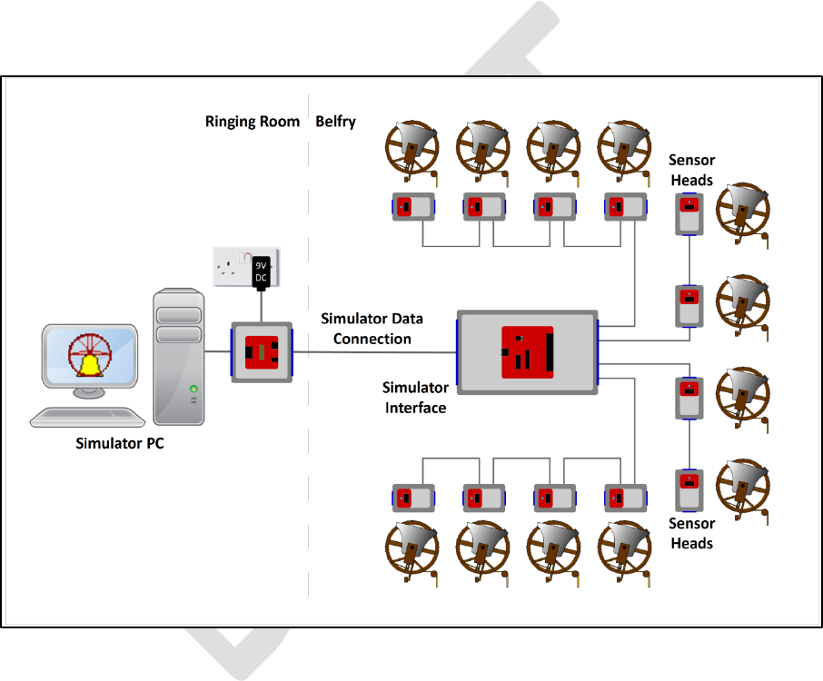
The following diagram illustrates the general arrangement of a Simulator installation using a sensor
aggregation hardware interface like the Liverpool Ringing Simulator.
Multiple Sensor Heads in the belfry, one per bell, are connected to a Simulator Interface. A single
data cable transmits the aggregated signals from the Simulator Interface to the Simulator PC in the
ringing room. The same cable feeds power from a low voltage power supply in the ringing room back
up to the Simulator Interface to power both Interface and Sensor Heads. The Type 2 simulator
supports up to 16 sensors.
In the ringing room, a PC runs a Simulator Software Package which interprets the received signals
and turns them into the simulated sound of bells.
Figure 2 – Simulator General Arrangement
This guide provides detailed build and installation information for the Simulator Interface, Power
Board and the Sensor Heads.

Type 2 Simulator – Build & Installation Guide 0.6
13
What You Will Need
Skills
The Liverpool Ringing Simulator is a Build-it-Yourself project. Based on feedback from constructors,
the Type 2 simulator has been re-designed to be easier to construct and install than the original
version, particularly around the cabling and enclosures.
Some prior experience of soldering and basic electronics kit construction will be helpful before you
build the Type 2 Liverpool Ringing Simulator, but there is nothing complex in the design, and there
are no surface mount components or cables to solder.
The ability to make simple voltage and resistance measurements with a multimeter will be helpful in
troubleshooting, but more advanced diagnostic equipment is not required.
Advice and guidance are available from the project via the contact form on the website.
Tools
• A small soldering iron suitable for electronics use – around 15 Watts is fine.
• Fine rosin-cored electronics solder – NOT plumbers’ acid core solder.
• A small pair of side cutters.
• A small pair of needle nose pliers
• A 20mm hole saw & arbor (eg Screwfix parts 22647 & 11336).
• A sharp utility knife.
• A 4.5mm drill bit.
• An electric drill – a bench mounted drill is best, but a hand-held drill can be used with care.
• Optional for optical sensors: An 18mm hole saw (eBay).
• Recommended: A basic multimeter with DC voltage and resistance ranges.
Parts
With the demise of Maplin, availability of electronic components from high street stores has been
drastically reduced, and you will probably need to source parts online. Suggested online suppliers
include Farnell (and their CPC consumer division – particularly useful for cables) and Rapid
Electronics. Parts may be also be sourced from reputable suppliers on eBay.
• Farnell – https://uk.farnell.com
• CPC – https://cpc.farnell.com
• Rapid Electronics - https://www.rapidonline.com
• eBay – https://www.ebay.co.uk
Where possible, Farnell or CPC part numbers have been given. Note that some smaller parts will only
be available in larger quantities than are required for a single simulator. You may want to use the
left overs to build more simulators for other local towers.
Type 2 Simulator – Build & Installation Guide 0.6
14
PCBs
Surplus development PCBs may be available from the Liverpool Ringing Simulator Project, please
enquire about availability via the contact form on the website.
The Type 2 simulator uses three types of PCB
5
:
• Simulator Interface Board – 1 required per installation
• Power Board – 1 required per installation
• Sensor Boards – 1 required per bell, per installation
Two suggested sources of PCBs are SeeedStudio in China, and OSH Park in the USA. Both take
typically around three weeks to deliver PCBs to the UK. PCB design files, known as “Gerber files”,
customised for each supplier, are available from the project GitHub repository:
• https://github.com/Simulators/simulator-type2
OSH Park
PCBs can be obtained from the OSH Park service in the USA, and links to each board type are listed
below. OSH Park produce very high quality “ENIG finish” boards, and charge $5 (US) per square inch
for three copies of a single type of board, including international airmail shipping.
Do NOT try to order panelised PCBs from OSH Park using the SeeedStudio Gerber files! There is no
cost advantage to doing so, and as OSH Park are themselves a panelisation service, trying to order
panelised PCBs will most likely result in your order being rejected.
Table 1 – OSH Park Permalinks
Board Type
OSH Park Permalink
Power Board
https://oshpark.com/shared_projects/L50bSYC4
Interface Board
https://oshpark.com/shared_projects/Q7Q4cz8d
Magneto-Resistive Sensor
https://oshpark.com/shared_projects/szHOys2B
Generic/Optical Sensor
https://oshpark.com/shared_projects/TPnh5Fjt
To order from OSH Park, browse the links above. There is no need to upload Gerber files.
SeeedStudio
The most cost-effective way of obtaining larger numbers of PCBs is to order them from a Chinese
PCB fabrication house, such as SeeedStudio’s “Fusion PCB” service. At the time of writing, 10 PCBs
6
of a single design are available for $4.90 US, plus postage.
The smaller Power and Sensor boards are designed as “panels” each containing multiple boards, four
Power Boards or six Sensor Boards per panel. Each panel is treated as a single PCB by the fabricator,
further reducing the total cost, so for example an order of 10 PCBs will result in enough boards for
60 sensors.
5
Printed Circuit Board
6
The minimum order quantity is actually five copies of a board, but the PCB cost is the same. There may be a
saving on postage cost, which is based on weight. This price is for HASL finish leaded solder PCBs, other
finishes have higher costs.
Type 2 Simulator – Build & Installation Guide 0.6
15
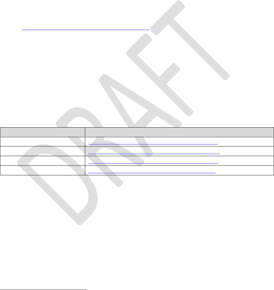
The following photograph shows panels of six Sensor Boards manufactured by SeeedStudio. These
can easily be split into separate boards.
Figure 3 – PCB Panels of Sensor Boards
To order from SeeedStudio, download the Gerber files from the project GitHub repository, then
browse the following link to the PCB Fusion service:
• https://www.seeedstudio.com/fusion_pcb.html
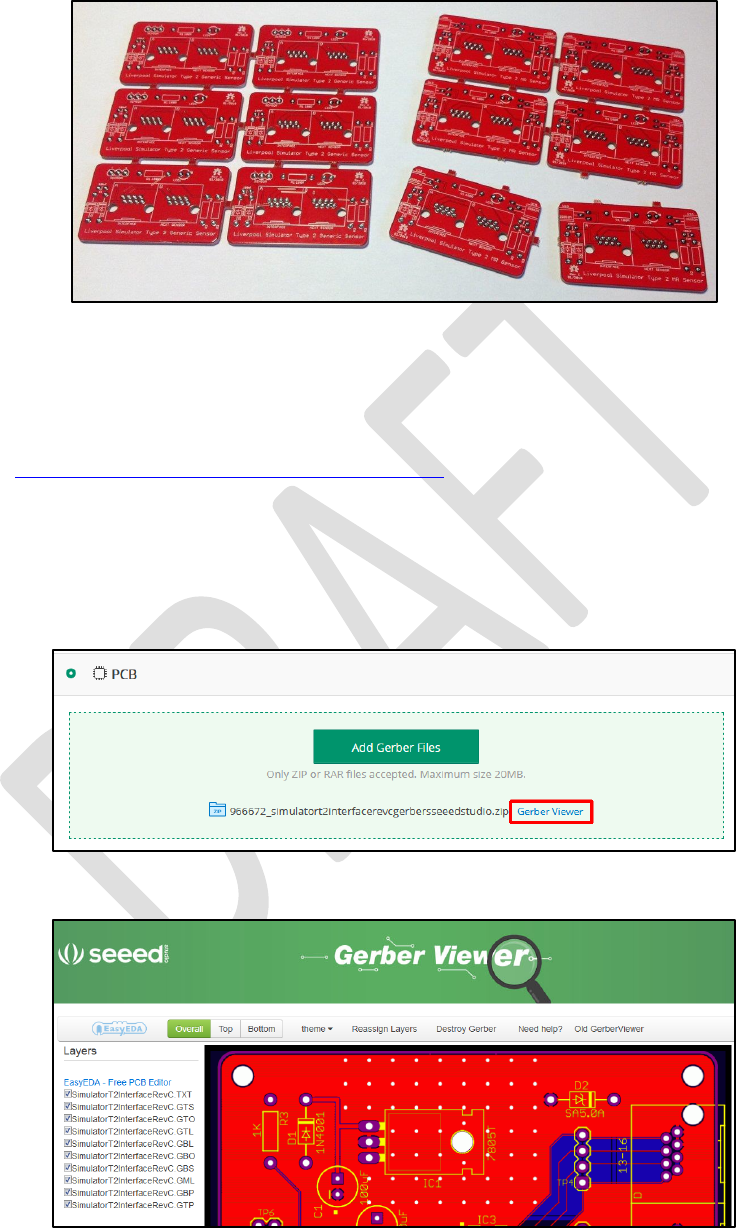
For each zipped Gerber file in turn, upload by clicking the Add Gerber Files button, complete the
order form, and add the boards to the shopping cart. Repeat the process with the Gerber file for
each type of board you want to order. Before confirming each board, use the online Gerber Viewer
to check that the board looks as it should. Follow the Gerber Viewer link in the upload box.
Figure 4 – SeeedStudio Upload Box
Figure 5 – SeeedStudio Gerber Viewer
Type 2 Simulator – Build & Installation Guide 0.6
16
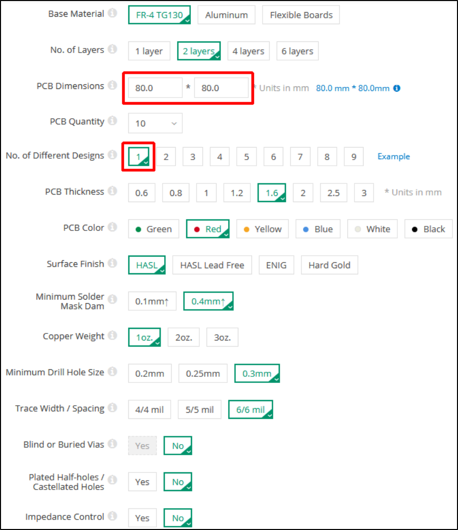
An example of a completed order form (for an Interface Board) is shown below:
Figure 6 – SeeedStudio Order Form
• The PCB Dimensions should be detected automatically from the uploaded file.
• The Number of Different Designs is always 1, even for the panelised PCBs.
• All other settings should be as shown above.
Type 2 Simulator – Build & Installation Guide 0.6
17
Simulator Assembly
This section describes the assembly of the Simulator Interface Board, Power Board, and the Sensor
Boards. It also covers the suggested enclosures.
Before you start construction of the Simulator hardware, check the log on the project GitHub
repository for any open or late-breaking issues which may affect your build:
• https://github.com/Simulators/simulator-type2/issues
It is recommended to give the completed Simulator Interface and Sensor PCBs a coat of protective
spray lacquer on both sides before installation, as a protection against damp. A suitable lacquer is
Electrolube CPL200H (Farnell 521462). Protect the connectors with masking tape before spraying.
Polarised Components
A number of the components of the Simulator are polarised and must be fitted the right way round
for correct operation. Guidance is given below on correct orientation of the polarised components,
but if in any doubt consult the component supplier or the manufacturer’s data sheets. Fitting a
polarised component the wrong may round may result in damage to the component.
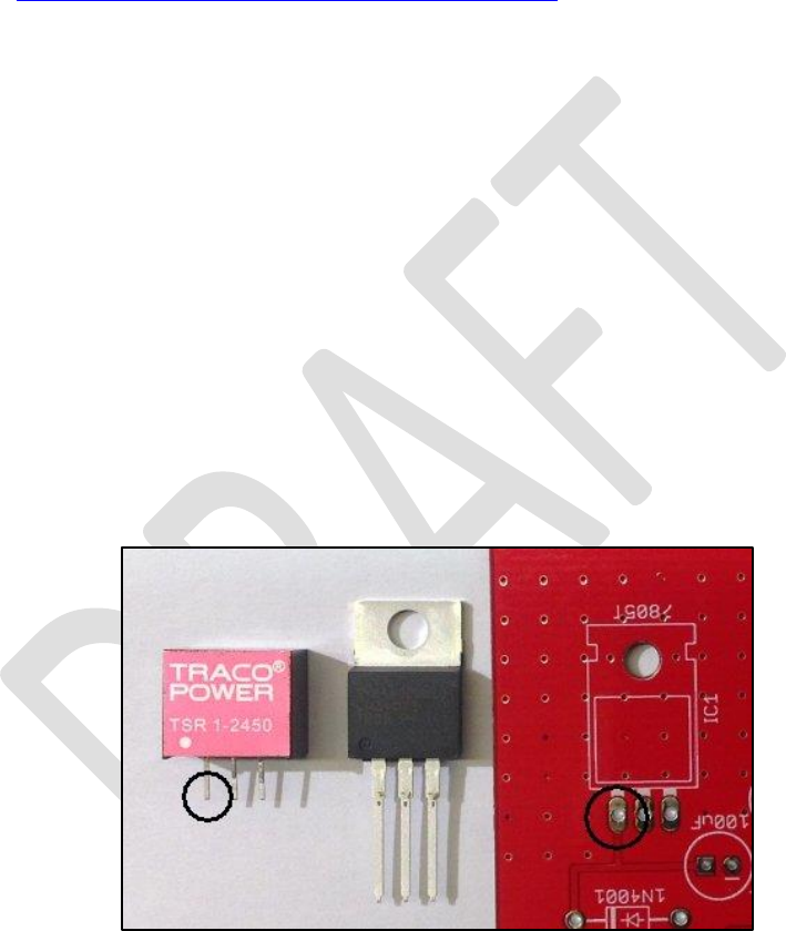
Voltage Regulators
The standard voltage regulator is fitted to the PCB with the metal tab flat against the surface of the
board. The alternative Traco Power TSR 1-2450 regulator has pin 1 indicated with a white dot. If
used, the alternative regulator must be fitted so that pin 1 is closest to the edge of the board, as
shown in the following photograph.
Figure 7 – Voltage Regulator Orientation
Type 2 Simulator – Build & Installation Guide 0.6
18
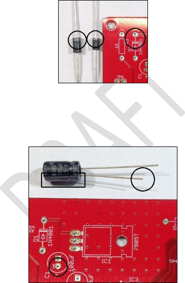
Diodes
The cathodes of the 1N4001 and SA5.0A diodes are indicated by a white band on the packages. The
diodes must be fitted so that the white band aligns with the corresponding white band printed on
the PCB, as shown in the following photograph.
Figure 8 – Diode Orientation
Electrolytic Capacitors
The negative side of electrolytic capacitors is usually indicated by a shorter lead, and by negative
markings on the side of the component. The electrolytic capacitors must be fitted with the negative
lead through the hole marked with the corresponding negative sign and white dot printed on the
PCB, as shown in the following photograph.
Figure 9 – Electrolytic Capacitor Orientation
Type 2 Simulator – Build & Installation Guide 0.6
19
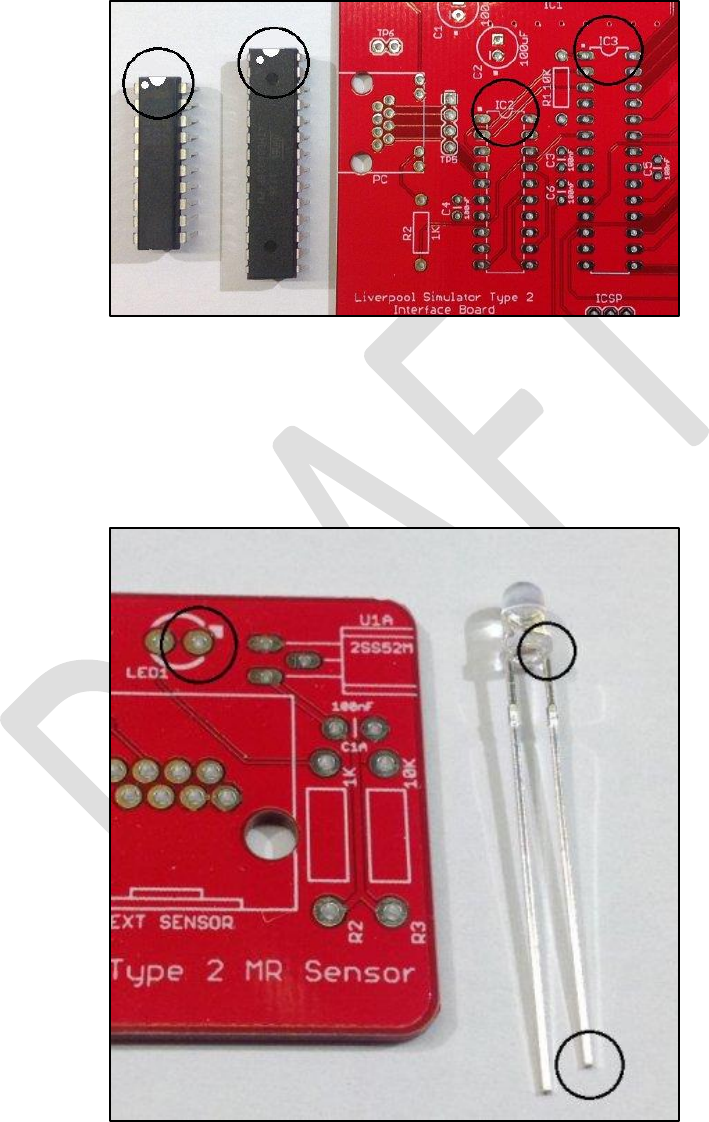
Integrated Circuits
The two integrated circuits have pin 1 marked with a dot, and/or a notch in the end of the package.
The ICs must be fitted with the notch/dot aligned with the notch and white dot printed on the PCB,
as shown in the following photograph.
Figure 10 – Integrated Circuit Orientation
LEDs
The cathode of the LEDs is usually indicated by a shorter lead, and/or by a flat on the side of the
plastic flange. The LEDs must be fitted with the cathode through the hole marked with the
corresponding white dot printed on the PCB, as shown in the following photograph.
Figure 11 – LED Orientation
Type 2 Simulator – Build & Installation Guide 0.6
20
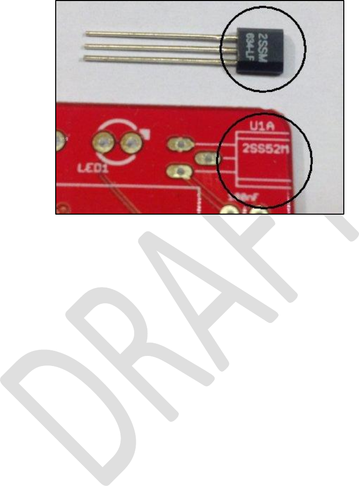
Magneto-Resistive Sensors
The magneto-resistive sensors are mounted flat on the PCB, with the chamfered and printed side
uppermost, as shown in the following photograph.
Figure 12 – Magneto-Resistive Sensor Orientation

Type 2 Simulator – Build & Installation Guide 0.6
21
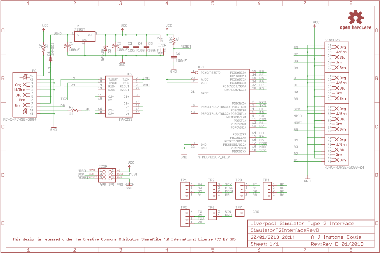
Simulator Interface Board
The Simulator Interface Board contains the power supply for the interface and Sensor Heads, the
microcontroller, a RS-232 serial line driver, plus power and diagnostic LEDs, and an ICSP
7
programming interface for firmware upload.
Parts List
Table 2 – Simulator Interface Board Parts List
Reference
Component
Notes
PCB
Type 2 Simulator Interface PCB
R1
10kΩ 0.25W Metal Film
Farnell 9341110
R2, R3
1kΩ 0.25W Metal Film
Farnell 9341102
C1, C2
100µF 25V Electrolytic (6.3mm Radial)
Farnell 9451188
C3, C4, C5, C6
100nF (0.1µF) 50V MLCC8 (2.54mm Radial)
Farnell 1457655
D1
1N4001
Farnell 1458986
D2
SA5.0A
Farnell 1886342
IC1
LM340T-5.0 (replacement for LM7805)
(Alternative: Traco Power TSR 1-2450)
Farnell 9490175
(Farnell 1696320)
IC2
MAX233EPP+G36
Farnell 2519158
IC3
ATmega328P-PU
Farnell 1715487
PC Connector
Amphenol RJHSE-5084
Farnell 1860578
Sensors Connector
Amphenol RJHSE-5080-04
Farnell 2709010
ICSP Header9
2x3-pin 0.1” Male Header
(cut from a longer strip10)
Farnell 1462888,
CPC CN18761, or eBay
IC Socket
20-pin, 0.3” pitch
Farnell 2445624
IC Socket
28-pin, 0.3” pitch
Farnell 2445626
Hardware
M3 Bolt (6mm/9mm) Nut, & Washer
Use 9mm if fitting a heatsink
Heatsink
TO-220 Heatsink (Optional)
Farnell 1703172
7
In-Circuit Serial Programming
8
Multi-Layer Ceramic Capacitor
9
Not required if you have obtained a microcontroller from the project with the firmware already loaded.
10
A ready-made 6-pin connector is available, Farnell 1593440, but the minimum order quantity is 50 units.
Type 2 Simulator – Build & Installation Guide 0.6
22
Schematic
Type 2 Simulator – Build & Installation Guide 0.6
23
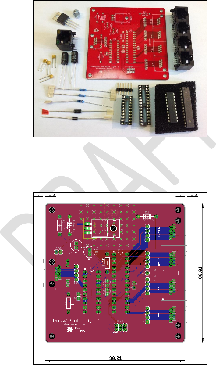
Parts
The following photograph shows the complete set of parts required for the Simulator Interface PCB.
Figure 13 – Simulator Interface Parts
PCB Layout
The following diagram shows the layout of the Simulator Interface PCB. All components are
mounted on the top (silkscreen) side of the board.
Figure 14 – Simulator Interface Board Layout

Type 2 Simulator – Build & Installation Guide 0.6
24
Construction
All the components on the Simulator Interface Board are mounted on top, silkscreen, side of the
board.
• Start by soldering the components with the lowest profile (resistors, ceramic capacitors),
then the remainder of the components in order of increasing height, ending with the RJ45
sockets.
• The use of IC sockets for IC2 & IC3 is strongly recommended.
• When fitting the voltage regulator, carefully bend the pins through 90 degrees, as described
below, so that the mounting hole in the tab lines up with the mounting hole in the PCB.
Secure the regulator to the board with an M3 nut, bolt and washer before soldering the pins.
A tiny smear of heatsink compound between the tab and board will improve heatsinking.
• There is no need to fit pins to any of the test point holes TP1 – TP7.
• If you plan to upload the firmware to the microcontroller in-situ using the method described
below, fit the 2 x 3-pin ICSP header pins. These can be omitted if you are using a separate
programmer or have obtained a microcontroller with the firmware already loaded.
• For high current installations, i.e. those with large numbers of optical sensors and/or very
short power/data cable runs, consider replacing the linear regulator with a switched buck
regulator such as the Traco Power TSR 1-2450. This is a direct drop-in replacement for the
standard TO-220 package regulator. The buck regulator is much more efficient than the
linear version, and reduces the heat dissipation.
• A small heatsink may be required for the voltage regulator, particularly in larger installations
with higher current (e.g. optical) sensors. Consider using a buck regulator instead. A heatsink
is not generally required for installations using the lower current magneto-resistive sensors.
Type 2 Simulator – Build & Installation Guide 0.6
25
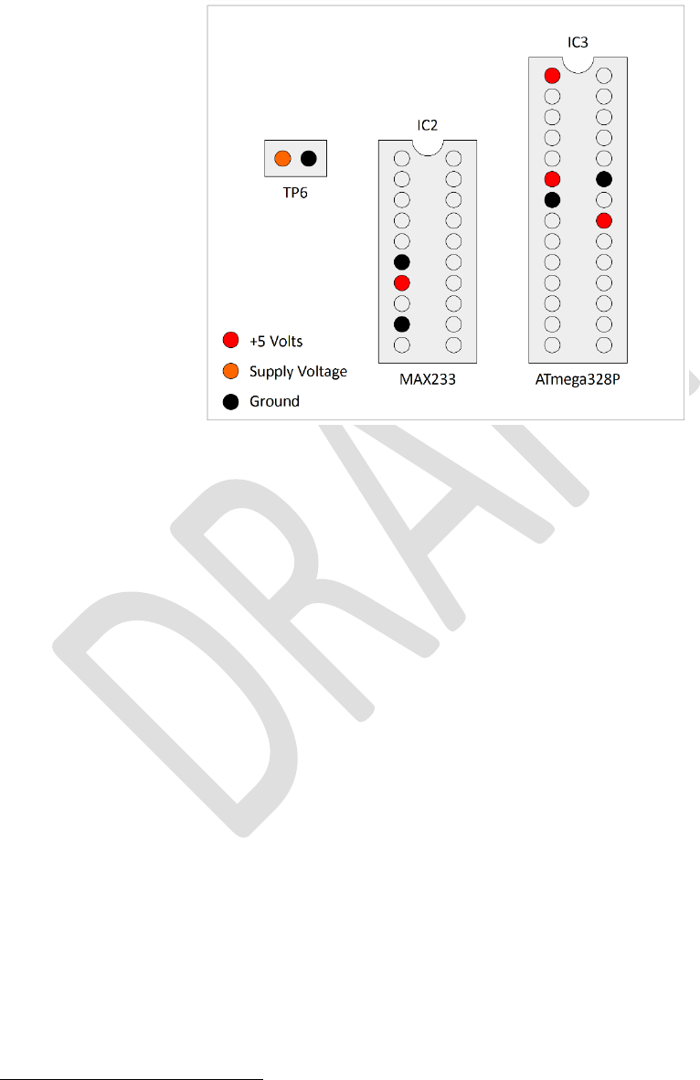
• Before fitting the socketed ICs, connect the board to a power supply (using the Power Board
and a short RJ45 cable) and check using a multimeter that the supply voltage appears on the
pins of TP6, and that +5V and 0V appear on the correct pins of the IC sockets. The pins are
identified in the diagram below. The green power LED in the “PC” RJ45 connector should
also light. Disconnect the power supply and fit the ICs.
Figure 15 – Voltage Check Pin Locations
• If the board is powered up at this point with no firmware installed on the microcontroller,
there will be no indication from the yellow diagnostic LED. This is normal.
• Pay close attention to the correct orientation of the polarised components D1, D2, C1, C2,
IC1, IC2 & IC3.
• The mounting lugs of the RJ45 connectors clip into the holes in the PCB. Make sure the
connector pins are correctly aligned with the holes before clipping the connector into the
board, and then soldering the pins.
• Note that the connectors overhang the edges of the PCB slightly. This is intentional and is to
allow for the board to be fitted into to a case in future.
Voltage Regulator
Bending Pins
The Simulator Interface Board PCB includes an alignment jig to assist you in bending the voltage
regulator pins accurately
11
.
• Bolt the voltage regulator to the reverse side of the board, at 90 degrees to its final position,
so that the pins hang over the edge of the board.
• Support the pins close to the body of the voltage regulator with a matchstick, and then bend
the pins carefully through 90 degrees, using the edge of the PCB as a guide.
11
From PCB Revision C onwards only. Do not use this method with older boards, the voltage regulator
alignment was adjusted in Revision C for this purpose.
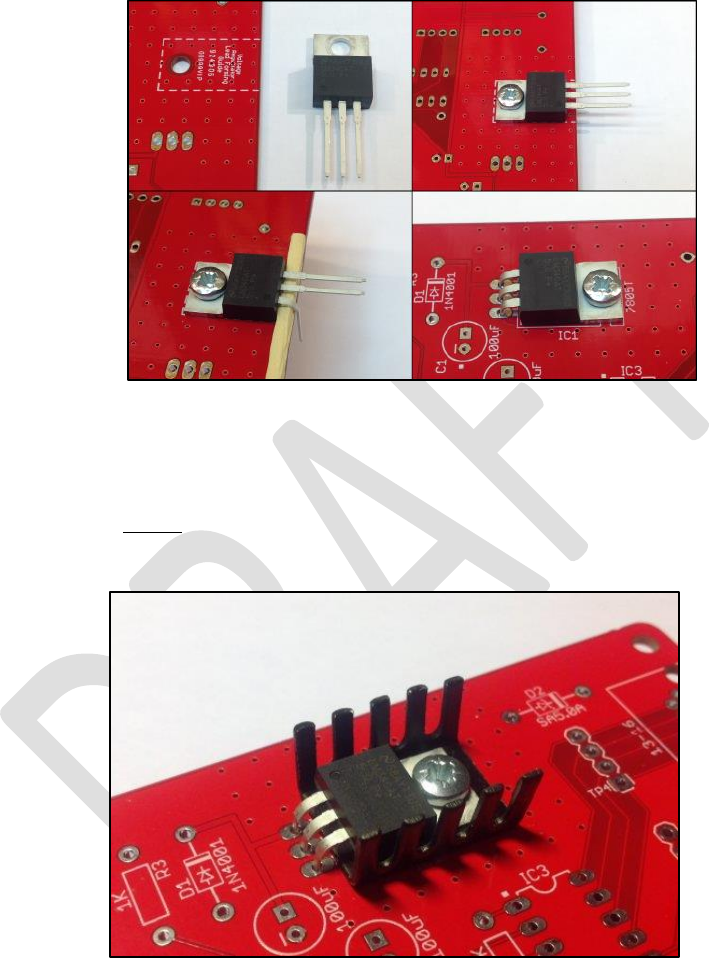
Type 2 Simulator – Build & Installation Guide 0.6
26
• Fit the voltage regulator to the right side of the PCB, and the pins and fixing hole should be
properly aligned.
• Bolt the voltage regulator to the PCB before soldering the pins.
• The process is illustrated in the following photograph.
Figure 16 – Bending Voltage Regulator Pins
Heatsink
If you are fitting an additional heatsink to the voltage regulator, bolt the voltage regulator and
heatsink to the PCB before soldering the pins. Make sure that the heatsink is not touching the PCB
solder pads for the voltage regulator pins. A 9mm bolt is required if fitting a heatsink.
Figure 17 – Voltage Regulator Heatsink
Type 2 Simulator – Build & Installation Guide 0.6
27
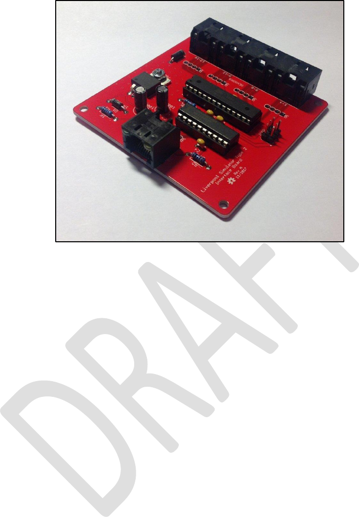
A completed Simulator Interface Board PCB is shown in the following photograph.
Figure 18 – Completed Simulator Interface PCB

Type 2 Simulator – Build & Installation Guide 0.6
28
Power Board
The Power Board is intended to be located close to the Simulator PC and enables the PC serial port
(or a USB-Serial adapter), and the power supply, to be connected to the power/data cable which
runs up to the Simulator Interface in the belfry. It also provides a protective fuse.
Parts List
Table 3 – Power Board PCB Parts List
Reference
Component
Notes
PCB
Type 2 Power Board PCB
PC Connector
Right Angle PCB D Sub Connector 9 Pin
Farnell 1848372
Interface Connector
Amphenol RJHSE-5080
Farnell 1860577
Power Connector
DC Power Connector 5mm PCB Mount
Farnell 1854512
Fuse Holder
20mm PCB Mount Fuse Holder
Farnell 2461158
Fuse
20mm 800mA Quick Blow Fuse
Farnell 2461215
Type 2 Simulator – Build & Installation Guide 0.6
29
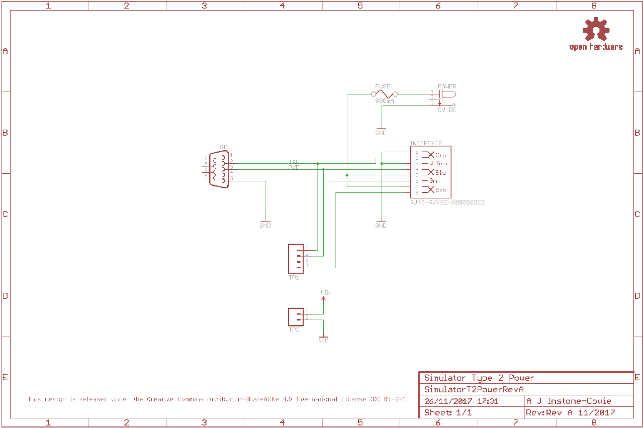
Schematic

Type 2 Simulator – Build & Installation Guide 0.6
30
Parts
The following photograph shows the complete set of parts required for the Power Board PCB.
Figure 19 – Power Board Parts
PCB Layout
The following diagram shows the layout of the Power Board PCB. All components are mounted on
the top (silkscreen) side of the board.
Figure 20 – Power Board Layout
Construction
All the components on the Power Board are mounted on top, silkscreen, side of the board.
• If your Power Board came from a panelized PCB, lightly file down any remaining nibs from
the edges of the board.
• Start by soldering the components with the lowest profile, then the remainder of the
components in order of increasing height.
• There is no need to fit pins to the test point holes TP1 – TP2.
Type 2 Simulator – Build & Installation Guide 0.6
31
• Fit a 20mm 800mA quick blow fuse to the fuse holder.
• Note that the connectors overhang the edges of the PCB slightly. This is intentional and is to
allow for the board to be fitted into to a case in future.
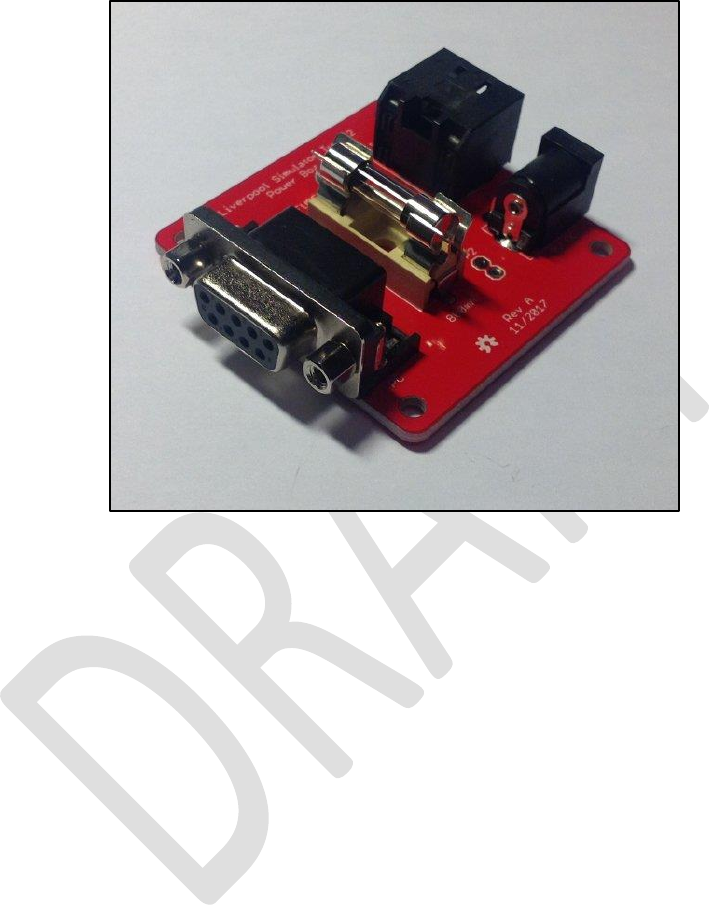
A completed Power Board PCB is shown in the following photograph.
Figure 21 – Completed Power Board PCB
Type 2 Simulator – Build & Installation Guide 0.6
32
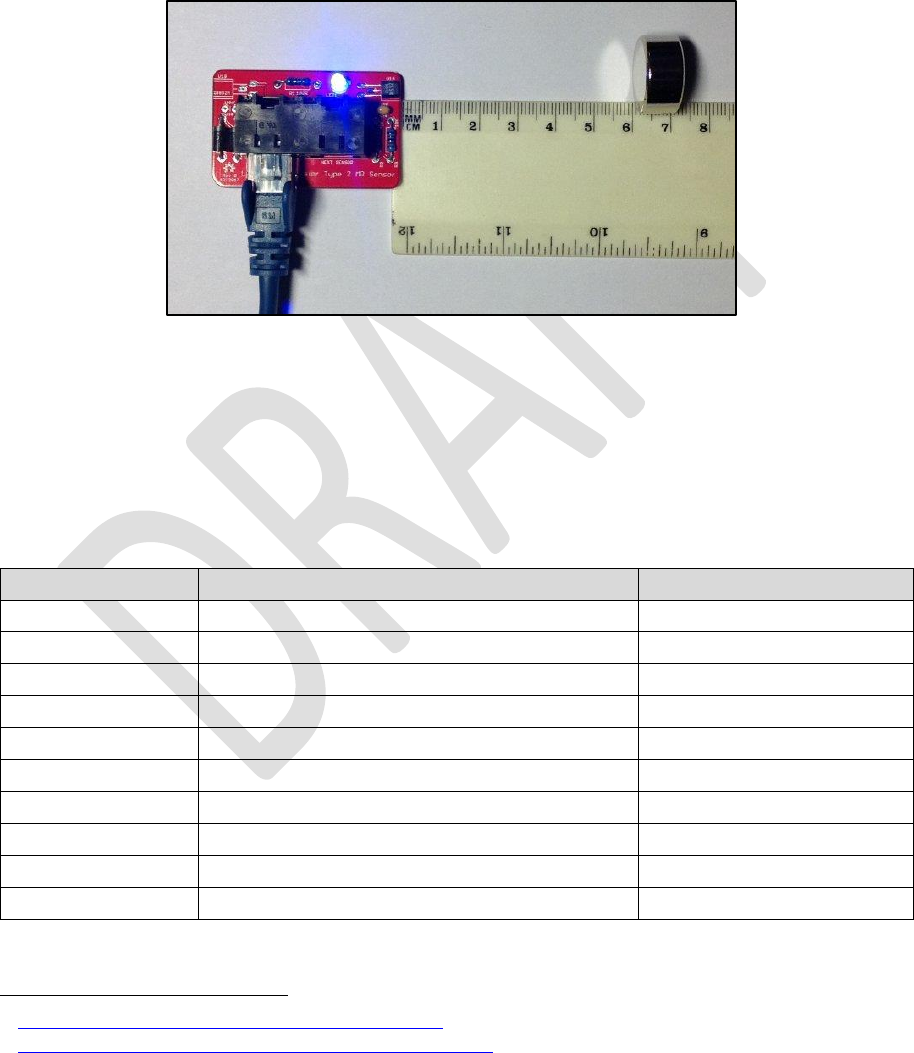
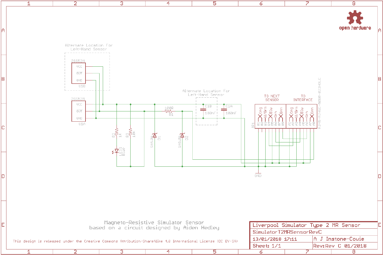
Magneto-Resistive Sensor
The magneto-resistive sensor, which is based on a design
12
by Aidan Hedley, uses a Honeywell
magneto-resistive sensor IC
13
, activated by a small, powerful rare earth magnet mounted on the
wheel shroud. This sensor has no moving or optical parts and is completely free of optical
interference. It also draws much less current than most optical sensors.
Using a magnet of the type suggested below, the absolute maximum operating distance of the
prototype is approximately 60mm (face of magnet to face of sensor). In practice a maximum
operating distance of approximately 30-40mm is recommended.
Figure 22 – Magneto-Resistive Sensor Demonstration
The sensor PCB contains all the components of the sensor, including the magneto-resistive sensor
itself, a diagnostic LED, and associated components. Build one sensor PCB for each bell you want to
connect to the simulator.
Parts List
Table 4 – Magneto-Resistive Sensor Board Parts List
Reference
Component
Notes
PCB
Type 2 Magneto-Resistive Sensor PCB
R1
100Ω 0.25W Metal Film
Farnell 9341099
R2
1kΩ 0.25W Metal Film
Farnell 9341102
R3
10kΩ 0.25W Metal Film
Farnell 9341110
C1
100nF (0.1µF) 50V MLCC (2.54mm Radial)
Farnell 1457655
LED1
Blue 3mm
Farnell 1863182
D1, D2
SA5.0A
Farnell 1886342
IC1
Honeywell 2SS52M
Farnell 3111519
Connector
AMP TE Connectivity 5406526-114
Farnell 2452587
Operating Magnet
N52 grade, 20mm x 10mm Neodymium
eBay
12
http://www.gremlyn.plus.com/ahme/mag_sen.html
13
http://sensing.honeywell.com/product-page?pr_id=36114
14
The Amphenol RJHSE-5080-02 connector originally specified is no longer stocked by Farnell. The alternative
AMP TE Connectivity part 5406526-1 is a direct replacement.
Type 2 Simulator – Build & Installation Guide 0.6
33
Schematic
Type 2 Simulator – Build & Installation Guide 0.6
34
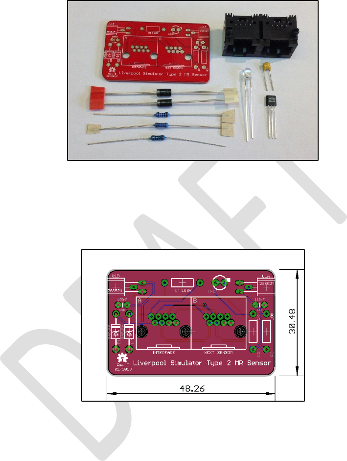
Parts
The following photograph shows the complete set of parts required for one Magneto-Resistive
Sensor Board.
Figure 23 – Magneto-Resistive Sensor Board Parts
PCB Layout
The following diagram shows the layout of a Magneto-Resistive Sensor PCB. All components are
mounted on the top (silkscreen) side of the board.
Figure 24 – Magneto-Resistive Sensor Board Layout
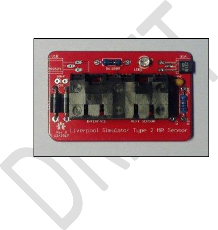
Construction
All the components on the Magneto-Resistive Sensor Board are mounted on top, silkscreen, side of
the board.
• If your Sensor Board came from a panelized PCB, lightly file down any remaining nibs from
the edges of the board. The board is intended to be a close fit in the suggested enclosure.
• Sensors can be constructed as right-handed or left-handed, to suit the installation in the
belfry. Fit sensor U1 and capacitor C1 at positions U1A/C1A for a right-handed sensor (as
shown in the pictures in this section), or at U1B/C1B for a left-handed sensor.
• Start by fitting the sensor IC. Carefully bend the pins through 90 degrees using needle nose
pliers, so that the sensor sits flat against the PCB, with the end of the sensor flush with the
edge of the board.
Type 2 Simulator – Build & Installation Guide 0.6
35
• Then solder the remaining components, starting with those with the lowest profile
(resistors, ceramic capacitors), then the remainder of the components in order of increasing
height, ending with the RJ45 socket.
• Pay close attention to the correct orientation of the polarised components D1, D2, U1, LED1.
• The mounting lugs of the RJ45 connector clip into the holes in the PCB. Make sure the
connector pins are correctly aligned with the holes before clipping the connector into the
board.
• There is an additional mounting hole in the PCB which allows for the dual RJ45 connector to
be replaced with a single RJHSE-5080 version in the “Interface” position. This is optional and
intended for a sensor to be located at the end of a chain of sensors. To allow for maximum
flexibility when cabling the sensors, you may choose to fit dual connectors to all sensor
boards.
A completed right-handed Magneto-Resistive Sensor PCB is shown in the following photograph.
Figure 25 – Completed Magneto-Resistive Sensor PCB (Right-Handed)

Type 2 Simulator – Build & Installation Guide 0.6
36
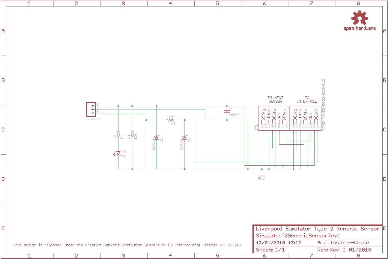
Infra-Red & Other Sensors
The Generic Sensor Board is designed to allow other types of sensor to be connected to the
simulator interface, provided these are electrically compatible with the system
15
. It can also be used
to build alternative infra-red sensors similar to those used in the original Liverpool Ringing Simulator.
Parts List
Table 5 – Generic Sensor Board Parts List
Reference
Component
Notes
PCB
Type 2 Generic Sensor PCB
R1
100Ω 0.25W Metal Film
Farnell 9341099
R2
1kΩ 0.25W Metal Film
Farnell 9341102
R3
10kΩ 0.25W Metal Film
Farnell 9341110
C1
100nF (0.1µF) 50V MLCC (2.54mm Radial)
Farnell 1457655
LED1
Yellow 3mm
Farnell 2112098
D1, D2
SA5.0A
Farnell 1886342
Sensor Header
1x3-pin 0.1” Male Header
(cut from a longer strip)
CPC CN18761 eBay
Connector
AMP TE Connectivity 5406526-116
Farnell 2452587
Infra-Red Sensor
E18-D80NK Infra-Red Obstacle Sensor
Hobby Components17
4tronix18
15
See Technical Reference Guide for more information.
16
The Amphenol RJHSE-5080-02 connector originally specified is no longer stocked by Farnell. The alternative
AMP TE Connectivity part 5406526-1 is a direct replacement.
17
http://hobbycomponents.com/sensors/213-ir-infrared-obstacle-avoidance-sensor-e18-d80nk
18
https://shop.4tronix.co.uk/collections/sensors/products/ir-infrared-obstacle-sensor
Type 2 Simulator – Build & Installation Guide 0.6
37
Schematic
Type 2 Simulator – Build & Installation Guide 0.6
38
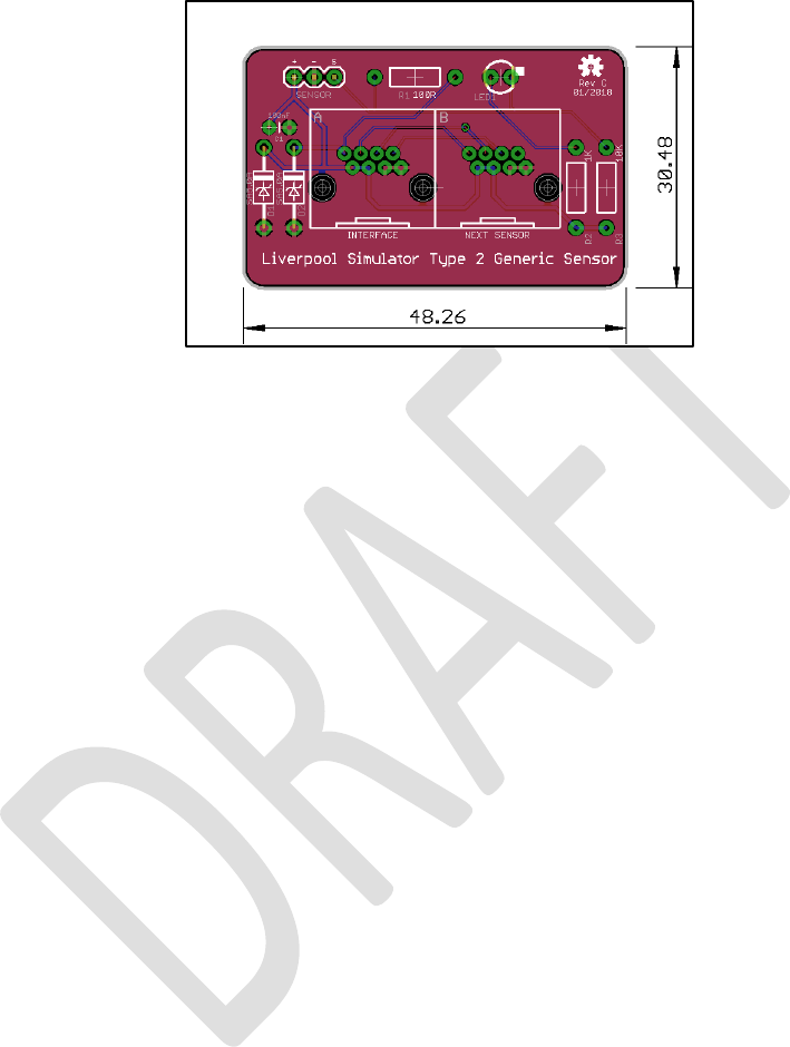
PCB Layout
The following diagram shows the layout of a Generic Sensor PCB. All components are mounted on
the top (silkscreen) side of the board.
Figure 26 – Magneto-Resistive Sensor Board Layout
Construction
All the components on the Generic Sensor Board are mounted on top, silkscreen, side of the board.
• If your Sensor Board came from a panelized PCB, lightly file down any remaining nibs from
the edges of the board. The board is intended to be a close fit in the suggested enclosure
when used to build an infra-red sensor.
• Solder the components, starting with the components with the lowest profile (resistors,
capacitor), then the remainder of the components in order of increasing height, ending with
the RJ45 socket.
• Pay close attention to the correct orientation of the polarised components D1, D2, LED1
(and to the connection to the infra-red sensor, if used).
• The mounting lugs of the RJ45 connector clip into the holes in the PCB. Make sure the
connector pins are correctly aligned with the holes before clipping the connector into the
board.
• There is an additional mounting hole in the PCB which allows for the dual RJ45 connector to
be replaced with a single RJHSE-5080 version in the “Interface” position. This is optional and
intended for a sensor to be located at the end of a chain of sensors. To allow for maximum
flexibility when cabling the sensors, you may choose to fit dual connectors to all sensors
boards.
Type 2 Simulator – Build & Installation Guide 0.6
39
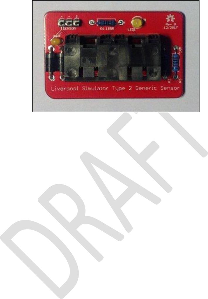
A completed Generic Sensor PCB is shown in the following photograph.
Figure 27 – Completed Generic Sensor PCB
Type 2 Simulator – Build & Installation Guide 0.6
40
Infra-Red Sensor
As an alternative to the magneto-resistive sensors, an infra-red sensor can be built based on a
commercially available modulated infra-red detector unit, marketed as an “obstacle sensor” for
educational robotics projects. These sensors are available pre-assembled and are relatively
inexpensive, and consequently the sensors are relatively straightforward to construct.
• The sensor emits and detects infra-red light modulated at high frequency. This makes the
sensor much less sensitive than visible light or unmodulated infra-red sensors to
interference from ambient lighting conditions.
• A 30mm length of 20mm black plastic conduit is used as a light shield. Once the sensor is
fitted to the enclosure, lightly file or sand the exposed threads so that the shielding tube is a
firm tight push fit on the end of the sensor.
• The infra-red sensor is mounted through the side of an enclosure using the plastic nuts
supplied with the sensor. These should be tightened finger-tight only; do not use tools.
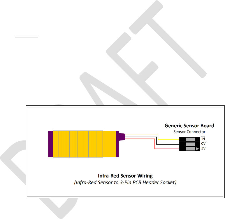
• It is essential to check that order of the wires in the sensor connector matches the order of
the pins. The red (+5V) wire should go to the leftmost pin, the black (0V) wire to the centre
pin, and the yellow (signal) wire to the rightmost pin.
• If the wires in the connector are in a different order, re-arrange them by gently prising up
the plastic tabs and sliding the pin out of the housing. Slide them back in in the correct
order, ensuring that the plastic tabs are gently pushed down to lock them in place.
The wiring of the infra-red sensor is illustrated in the following diagram:
Figure 28 – Infra-Red Sensor Wiring

Type 2 Simulator – Build & Installation Guide 0.6
41
Enclosures
The suggested enclosures for the Simulator Interface, Power Board and Sensors are from the “Really
Useful” series of plastic boxes, widely available from hobby and stationery shops, or direct from the
manufacturer
19
.
• Drilling large diameter holes with twist drills can result in bit grabbing and damage to the
enclosure. Use a 20mm hole saw
20
for cable holes, this makes the process of drilling the
enclosure much easier and safer.
• Support the inside surface of the enclosure with a block of scrap wood when cutting the
holes and cut at a low speed.
• Clean up any rough edges or swarf with a sharp knife.
• Drill any additional holes required in the base of each sensor enclosure to suit your
mounting method.
• Cables are run into the enclosures via PVC grommets, which provide some protection
against dust and moisture.
Parts List
Table 6 – Enclosures Parts List
Reference
Component
Notes
Simulator Interface Board
Really Useful Box® 0.75 Litre
195 x 135 x 55mm
Power Board
Really Useful Box® 0.75 Litre
195 x 135 x 55mm
Magneto-Resistive Sensor
Really Useful Box® 0.07 Litre
90 x 65 x 30mm, 1 per Sensor
Infra-Red Sensor
Really Useful Box® 0.14 Litre
90 x 65 x 55mm, 1 per Sensor
Grommets
20mm Closed Grommets
Screwfix 18603
19
http://www.reallyusefulproducts.co.uk/
20
Frequently used by electricians.
Type 2 Simulator – Build & Installation Guide 0.6
42
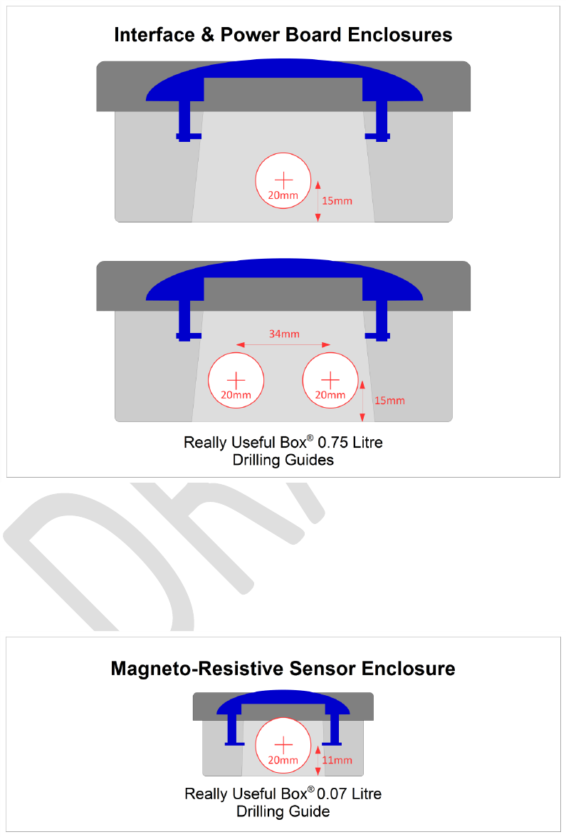
Simulator Interface & Power Boards Enclosure
The following diagram shows the holes required in a 0.75 litre Really Useful for both the Simulator
Interface and Power boards.
Figure 29 – Simulator Interface & Power Board Enclosure Drilling Guide
Magneto-Resistive Sensors Enclosure
The following diagram shows the hole required in a 0.07 litre Really Useful for the Magneto-Resistive
Sensor Board. The hole will catch the overhanging lip of the box slightly; this does not matter. There
is no difference between right-hand and left-hand sensors.
Figure 30 – Magneto-Resistive Sensor Enclosure Drilling Guide
Type 2 Simulator – Build & Installation Guide 0.6
43
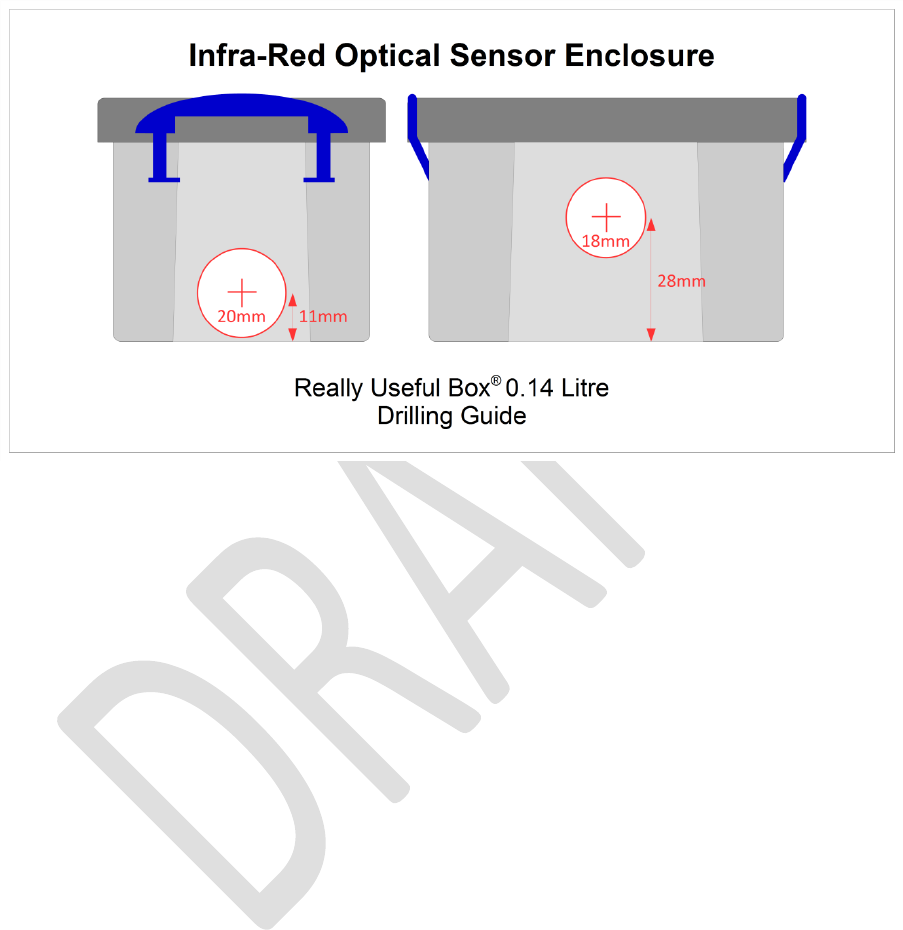
Infra-Red Sensors Enclosure
The following diagram shows the holes required in a 0.07 litre Really Useful for an infra-red sensor
using the Generic Sensor Board. Cut the 18mm hole to suit either a right-hand or left-hand
installation as needed.
Figure 31 – Infra-Red Sensor Enclosure Drilling Guide
Grommets
Cables are run into the enclosures via PVC grommets, which provide protection against dust and
moisture.
• Drill one or two holes in each closed grommet. A diameter of 4.5mm should ensure a snug fit
around the RJ45 cables, but this can be adjusted to suit.
• For sensors, offset the holes slightly, as shown in the twin hole example below, as this allows
the cables to sit closer to the base of the enclosure.
• Using a sharp knife, make a cut as shown from the hole (link the holes if there are two),
through the edge of the grommet.

Type 2 Simulator – Build & Installation Guide 0.6
44
The following diagram shows examples of the holes and cuts required in the grommets.
Figure 32 – Grommets Drilled & Cut

Type 2 Simulator – Build & Installation Guide 0.6
45
Completed Assemblies
Simulator Interface
The following photograph shows a completed Sensor Interface, with cables installed for four chains
of sensors.
Figure 33 – Completed Sensor Interface
Power Board
The following photograph shows a completed Power Board, with a USB-Serial adapter also inside the
enclosure.
Figure 34 – Completed Power Board
Type 2 Simulator – Build & Installation Guide 0.6
46
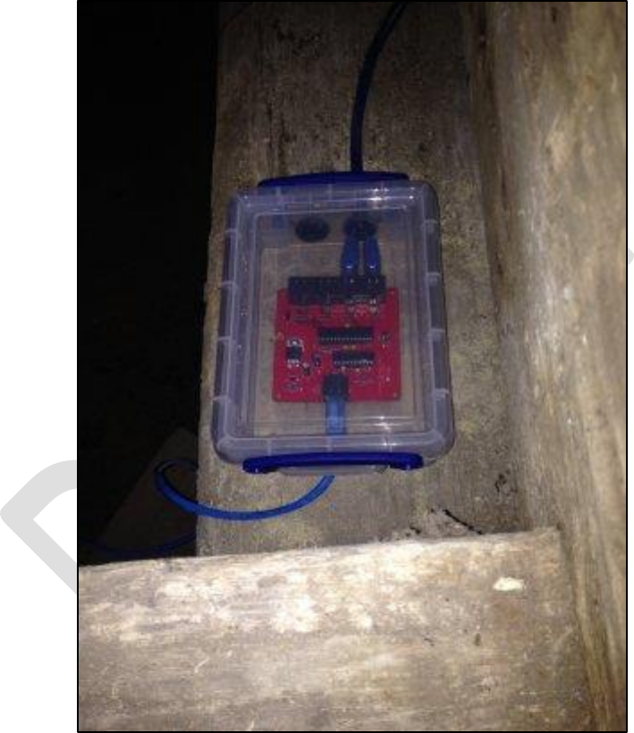
Magneto-Resistive Sensor
The following photograph shows a completed Magneto-Resistive Sensor. The PCB is a snug fit in the
bottom of the enclosure. If the sensor is to be mounted vertically, a cable tie around the RJ45 cables
on the inside of the box will stop the board from slipping down the inside of the box.
Figure 35 – Completed Magneto-Resistive Sensor
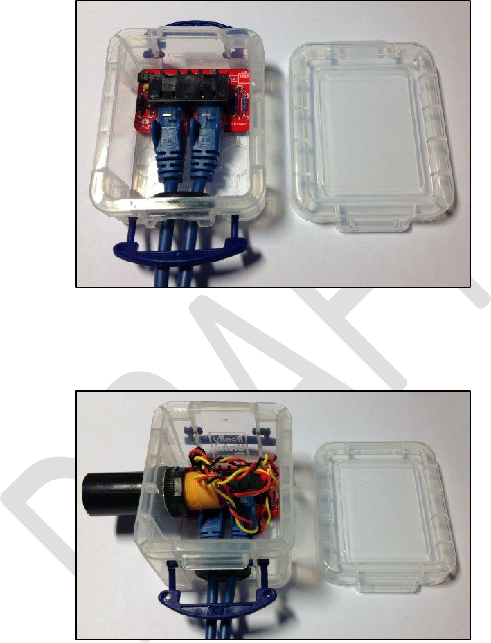
Infra-Red Sensor
The following photograph shows a completed infra-red sensor, using a Generic Sensor Board.
Figure 36 – Completed Infra-Red Sensor

Type 2 Simulator – Build & Installation Guide 0.6
47
Firmware Upload
Note: If you have obtained a microcontroller from the project with the firmware already uploaded
to it, you can skip the whole of this section, and move on to the Installation section.
The firmware for the Simulator Interface Board is released under the GNU General Public Licence
(GPL), Version 3, and the source code and other supporting files can be downloaded from GitHub.
• https://github.com/Simulators/simulator-type2
The Simulator Interface firmware is held in non-volatile flash memory on the ATmega328P
microcontroller. It should only be necessary to re-upload the software in the event that the
microcontroller is replaced, the flash memory has become corrupted, or the Simulator Interface
firmware requires updating.
The firmware code needs to be uploaded to the microcontroller on the Simulator Interface PCB.
Although the software development environment is based on the Arduino platform, the Simulator
Interface does not use the Arduino bootloader, and it is not possible to upload the firmware over the
interface’s RS-232 serial port. Firmware is uploaded using a hardware programmer via the ICSP
header pins provided on the interface PCB.
There are three main options for the hardware programmer:
• A dedicated hardware ISP programmer such as the AVR ISP
21
.
• An Arduino add-on board or shield such as the Arduino ISP
22
or similar shield.
• An Arduino board (with one additional component) used as an ISP programmer.
The last of these requires no special hardware, and is the approach described in this document.
There are also many tutorials online, including on the Arduino website
23
.
21
http://www.atmel.com/tools/avrispmkii.aspx
22
http://www.arduino.cc/en/Main/ArduinoISP
23
http://www.arduino.cc/en/Tutorial/ArduinoISP
Type 2 Simulator – Build & Installation Guide 0.6
48
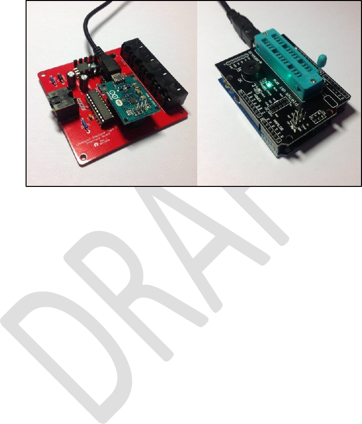
Hardware Programmer Options
The following photograph shows two examples of hardware programmers. On the left, an
ArduinoISP device is connected directly the ICSP programming pins of a completed Simulator
Interface PCB. On the right, a generic programming shield (mounted on an Arduino Uno board) can
be used to upload firmware to the microcontroller before it is installed on the Simulator Interface
PCB.
Figure 37 – Hardware Programmers
If you have access to a hardware programmer, then you can use this to upload firmware to the
ATmega328P microcontroller. This guide describes an alternative method adapting an Arduino Uno
board as a programmer.
Type 2 Simulator – Build & Installation Guide 0.6
49
Preparing the Environment
Perform the following steps to prepare the PC software environment for compiling and uploading
the Simulator Interface firmware:
• Download and install the latest Arduino IDE package
24
. At the time of writing this was
version 1.6.12.
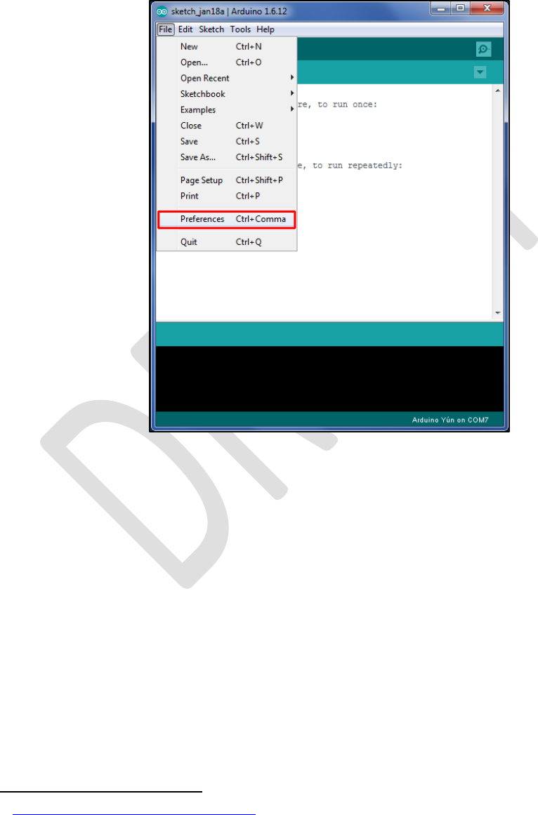
• Start the IDE, and open the program preferences by selecting File | Preferences.
Figure 38 – Arduino IDE Preferences Menu
24
http://www.arduino.cc/en/Main/Software
Type 2 Simulator – Build & Installation Guide 0.6
50
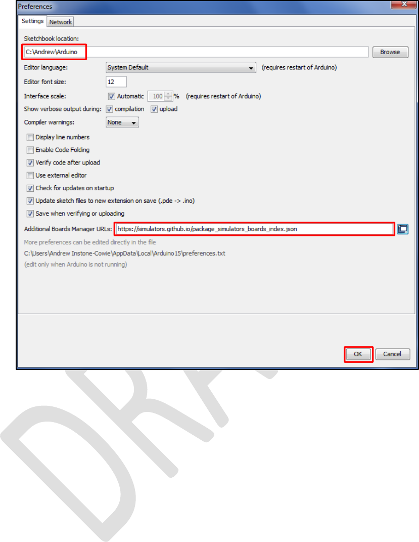
Figure 39 – Arduino IDE Sketchbook Location
• Make a note of the Sketchbook Location path. This is the directory into which the Simulator
Interface firmware must be downloaded in a later step.
• Add the URL for the Liverpool Simulator Project boards to the Additional Boards Manager
URLs field. The URL is:
https://simulators.github.io/package_simulators_boards_index.json
• Close the preferences dialogue by clicking OK.
Type 2 Simulator – Build & Installation Guide 0.6
51
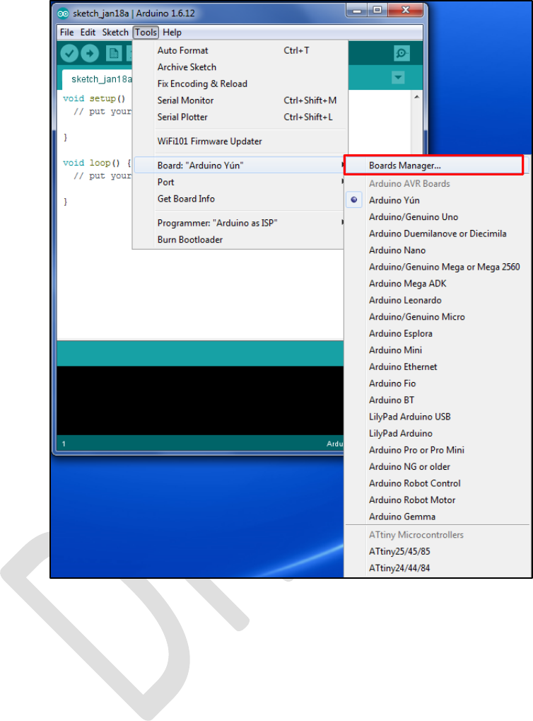
• Open the Boards Manager by selecting Tools | Board | Boards Manager.
Figure 40 – Arduino IDE Boards Manager Menu
Type 2 Simulator – Build & Installation Guide 0.6
52
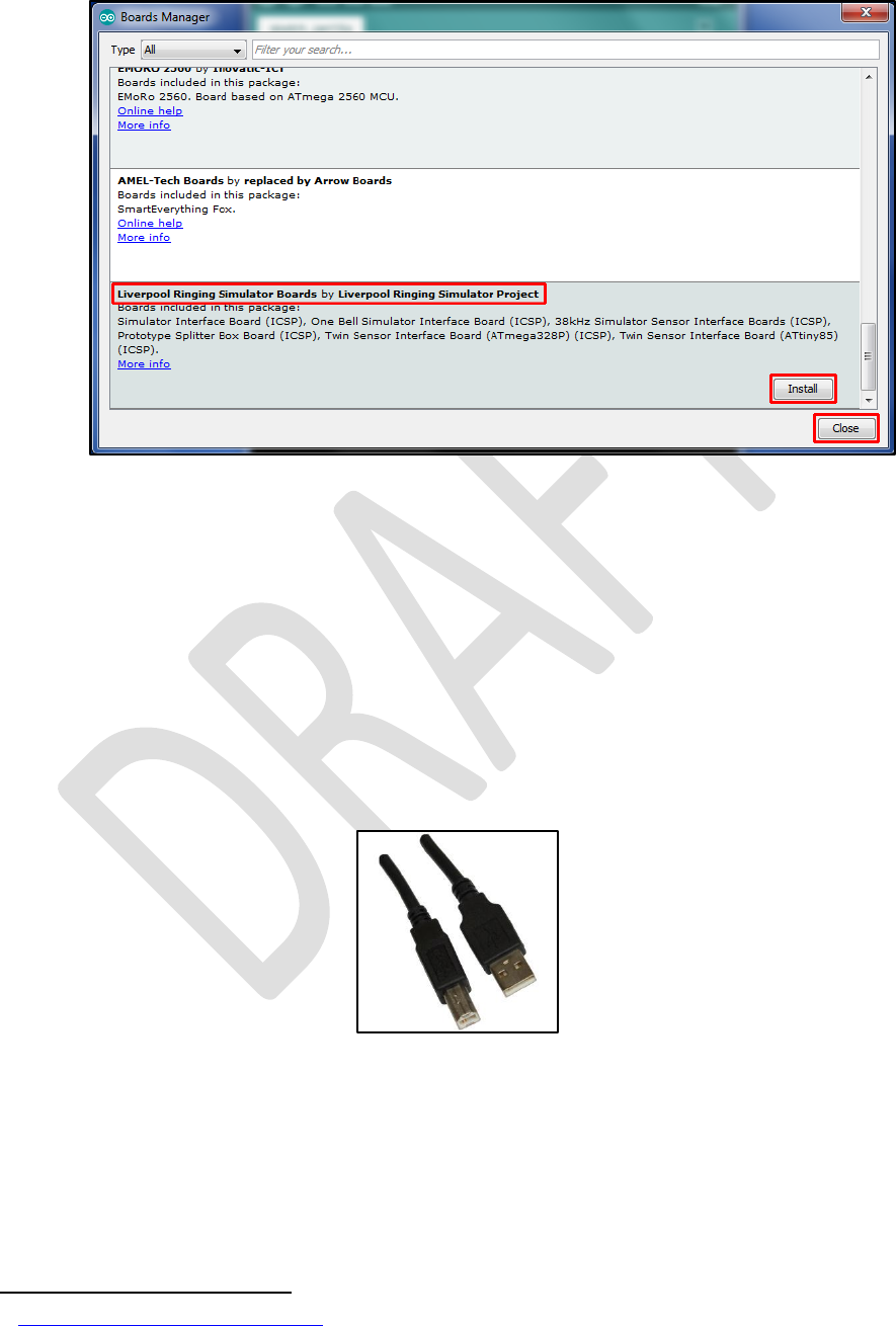
• Scroll down to the entry Liverpool Ringing Simulator Boards, click on the entry, and
then click Install. Then close the Boards Manager by clicking OK.
Figure 41 – Arduino IDE Board Manager
• Re-start the Arduino IDE.
The environment is now ready to set up the programmer.
Preparing the Programmer
The programmer is an unmodified Arduino Uno board running a sketch which allows it to operate as
an ISP programmer.
This requires an Arduino Uno board, and a Type A to Type B USB cable (sometimes known as a
printer cable).
Figure 42 – Arduino USB Cable
The Arduino website has instructions
25
on connecting the Arduino board to a computer, installing
drivers and setting up the IDE.
Perform the following steps to prepare the programmer Arduino Uno board:
25
http://arduino.cc/en/guide/windows
Type 2 Simulator – Build & Installation Guide 0.6
53
• Connect the B end of the USB cable to the Arduino Uno board to be used as the
programmer. From now on this board is referred to simply as the programmer.
• Connect the A end of the USB cable to the computer.
• Follow the instructions on the Arduino site to install drivers (if necessary), and select the
correct port and board type for the programmer in the IDE.
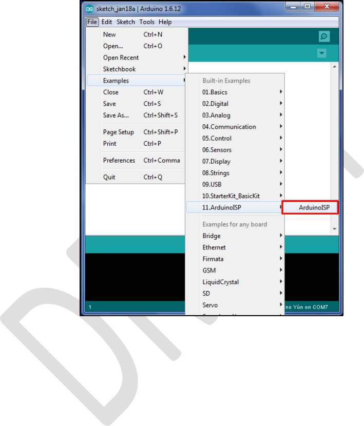
• Open the ArduinoISP software sketch (supplied as part of the default IDE installation) in the
Arduino IDE by selecting it from the File | Examples menu.
Figure 43 – Arduino IDE ISP Sketch Loading
Type 2 Simulator – Build & Installation Guide 0.6
54
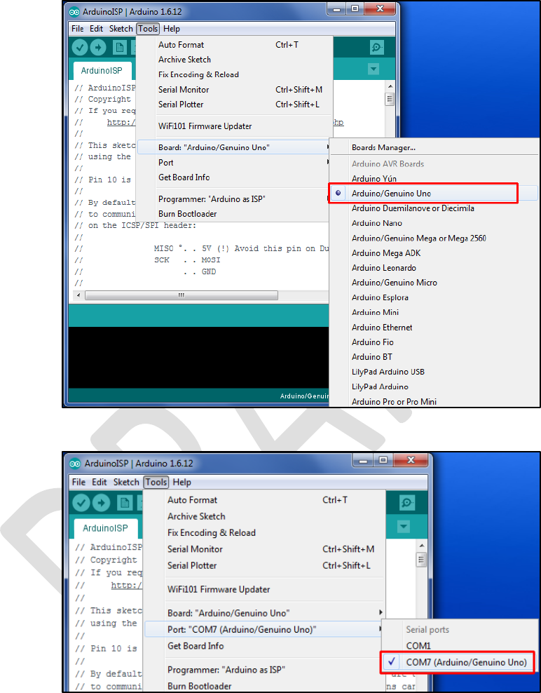
• On the Tools menu, ensure the correct board type for the programmer is selected
(Arduino/Genuino Uno, not Simulator Interface Board (Type 2) (ICSP)) and port. Correct these
if necessary.
Figure 44 – Arduino Programmer Board Selection
Figure 45 – Arduino Programmer Port Selection

Type 2 Simulator – Build & Installation Guide 0.6
55
• Click the upload (arrow) button on the IDE toolbar. The ArduinoISP code will be compiled
and uploaded to the programmer. Verify that the upload completed successfully by looking
for the Done uploading message.
Figure 46 – Arduino IDE ISP Upload
• A failed upload will be indicated by error messages in the status area at the bottom of the
IDE window.
• Disconnect the USB cable from the programmer.
Type 2 Simulator – Build & Installation Guide 0.6
56
• Connect a 10µF 25V electrolytic capacitor between the Reset and Ground pins of the
programmer, negative side to Ground. This prevents the IDE from resetting the programmer
and overwriting the ArduinoISP software, and allows the IDE to program the Simulator
Interface.
Figure 47 – Programmer with Capacitor
• Reconnect the USB cable to the programmer.
The programmer is now ready for use.
Setting the Fuses
Perform the following steps to set the microcontroller “fuses”. The fuses and their values are
explained in the Technical Reference Guide.
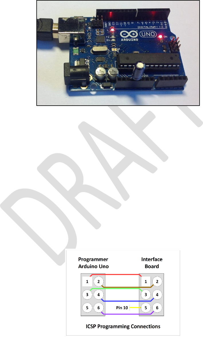
• Disconnect the USB cable from the programmer.
• Connect the ICSP pins on the Simulator Interface to the ICSP pins on the programmer with
jumper wires as shown in the following diagram.
• Pin 1 on the Simulator Interface PCB is bottom left, identified by a white dot.
• Pin 1 on the programmer is top left. Note that pin 5 on the Simulator Interface PCB is
connected to pin 10 on the programmer.
Figure 48 – Programmer Connections
Type 2 Simulator – Build & Installation Guide 0.6
57
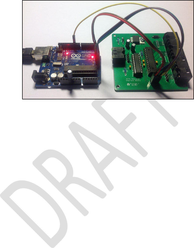
• The following photograph shows the programmer connected to an interface board, including
the connection to pin 10 of the programmer (yellow wire), not to the ICSP pin.
Figure 49 – Programmer Connected to Interface Board
• Reconnect the USB cable to the programmer.
Type 2 Simulator – Build & Installation Guide 0.6
58
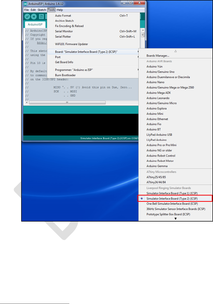
• On the Tools | Board menu, ensure the correct target board type to be programmed has
been selected, in this case Simulator Board Interface (Type 2) (ICSP)
26
.
Figure 50 – Arduino IDE Target Board Selection
26
If the Liverpool Ringing Simulator Project boards are not listed, go back and check that the boards have been
installed in the Boards Manager.
Type 2 Simulator – Build & Installation Guide 0.6
59
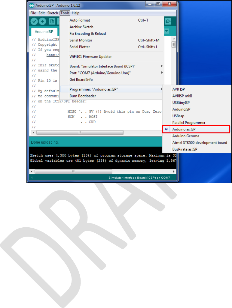
• On the Tools | Programmer menu, select Arduino as ISP as the programmer type.
Figure 51 – Arduino IDE Programmer Selection
Type 2 Simulator – Build & Installation Guide 0.6
60
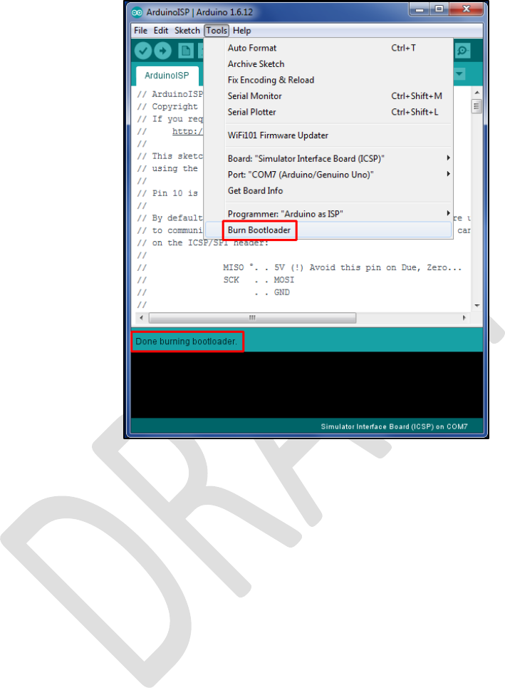
• On the Tools menu, select Burn Bootloader. The microcontroller fuses on the Simulator
Interface Board will be set. Verify that the burn process completed successfully by looking
for the Done burning bootloader message.
Figure 52 – Arduino IDE Burn Bootloader
• Important note: If a microcontroller previously used in an Arduino board is to be re-used on
the Simulator Interface board, carry out the steps above to set the fuses before removing
the microcontroller from the donor Arduino. Brand new ATmega328P-PU microcontrollers
should be configured to use the 8MHz internal clock by default, but ones previously used on
an Arduino will be configured to require an external crystal clock. Once you have set the
fuses, move the microcontroller from the donor Arduino to the Simulator Interface Board.
• Note that if new firmware is being uploaded to an existing Simulator Interface Board, there
should be no need to go through the steps to set the fuses every time, unless a change in
fuse values is required by the new firmware.
The microcontroller is now ready for firmware upload.
Firmware Upload
Perform the following steps to upload the Type 2 Simulator Interface firmware to the board.
• Connect the Simulator Interface Board to the programmer as described in the previous
section.

Type 2 Simulator – Build & Installation Guide 0.6
61
• Download and install the MemoryFree
27
and VTSerial
28
libraries. For convenience these
libraries are can also be found in the GitHub repository with the Simulator Interface
firmware. Note that the libraries can be installed straight from the compressed zip files by
selecting Add .ZIP Library from the Sketch | Include Library menu.
Figure 53 – Arduino IDE Add Library
• Download the Simulator Interface firmware from GitHub and unpack the files into the
Arduino IDE sketchbook directory noted earlier. Note that all the firmware files must be
unpacked into the directory; it is not possible to compile the firmware code from within a
downloaded zip file.
• Load the firmware into the Arduino IDE by double clicking the name of the main file in
Windows Explorer, e.g. Type2Interface_v3_2.ino.
• On the Tools | Board menu, as above ensure that the correct board type to be programmed
has been selected, in this case Simulator Board Interface (Type 2) (ICSP).
27
https://github.com/maniacbug/MemoryFree
28
http://www.hobbytronics.co.uk/tutorials-code/arduino-tutorials/arduino-vtserial-library
Type 2 Simulator – Build & Installation Guide 0.6
62
• On the Tools | Programmer menu, as above select Arduino as ISP as the programmer type.
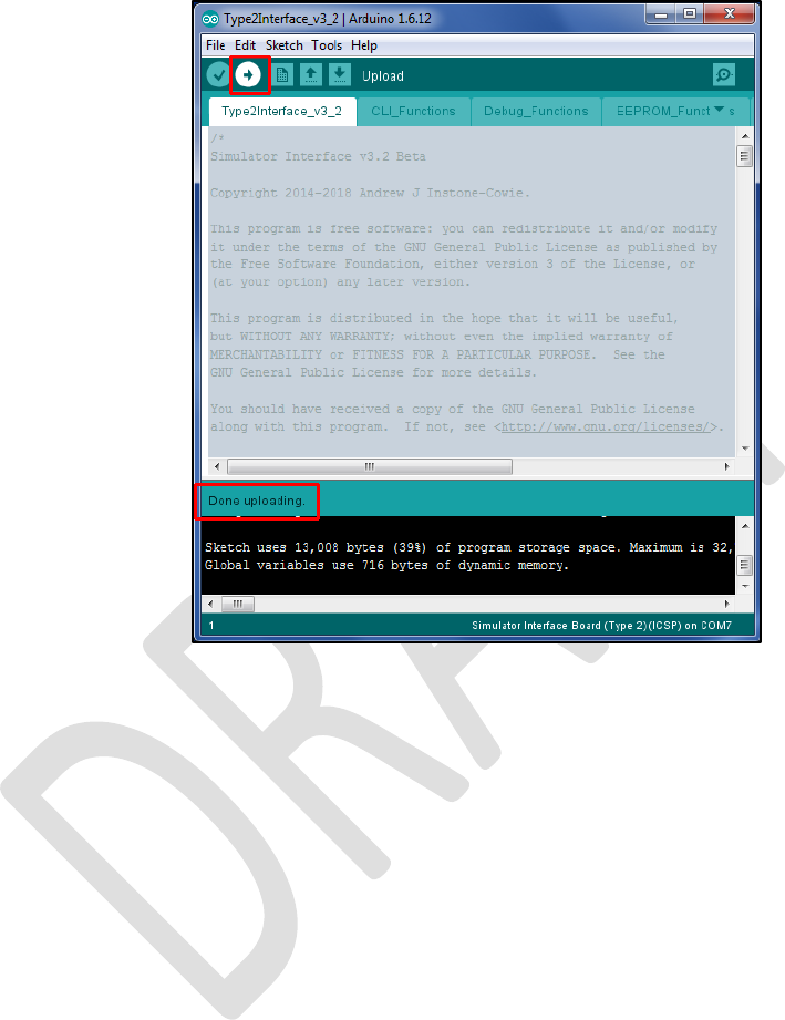
• Click the upload (arrow) button on the IDE toolbar. The Simulator Interface firmware will be
compiled and uploaded to the interface board. Verify that the upload completed successfully
by looking for the Done uploading message.
Figure 54 – Arduino IDE Firmware Upload
• A failed upload will be indicated by error messages in the status area at the bottom of the
IDE window.
• When the upload has completed the Simulator Interface board will be reset, and on
restarting the yellow diagnostic LED will flash according to the firmware version, for example
three long and two short flashes indicates firmware version 3.2.
• Disconnect the USB cable from the programmer.
• Disconnect the programmer from the Simulator Interface Board.
• Note that when uploading new firmware to an existing Simulator Interface Board, the Sensor
Head Cables and the Power/Data Cable must be disconnected from the Simulator Interface.
The Simulator Interface board now has the firmware installed and is ready for final assembly.
Type 2 Simulator – Build & Installation Guide 0.6
63
Simulator Installation
Simulator Interface
The Simulator Interface is located in the belfry, in a location convenient for routing cables to the
sensors and the power/data cable down to the ringing room. Try to pick a sheltered location where
the interface will be out of the way.
The following picture shows the Simulator Interface at Lois Weedon in the belfry. Note the two
cables for chains of sensors.
Figure 55 – Installed Simulator Interface
The Simulator Power/Data Cable is routed from the Simulator Interface down to the Simulator PC.
• The cable should be secured to prevent the weight of the cable pulling on the connectors.
• The minimum diameter of any holes along the cable route is approximately 12mm, to allow
the RJ45 connector to pass through (unless you are making your own cables in-situ).

Type 2 Simulator – Build & Installation Guide 0.6
64
Power Board
The Power Board enclosure is located near the Simulator PC. There is enough room in the enclosure
to house a USB-Serial adapter, if one is required.
Power Supply
A plug-in power supply is required to supply power to the Simulator Interface via the Power Board.
• A regulated DC power supply rated at least 1 Amp with multiple selectable output voltages is
recommended, for example Farnell 2802689 or similar.
• The output connector required is 2.1mm x 5.5mm, centre pin positive.
• The output voltage of the power supply should be adjusted so that the supply voltage at the
input to the Simulator Interface (measured at TP6) is at least 7.5 volts, with all sensors
connected.
• The supply voltage may be higher than that required to maintain 7.5 volts at the Interface,
but this will result in increased heat dissipation from the voltage regulator.
• As a guideline, a supply voltage of 9V is generally sufficient to maintain the required voltage,
with a 25m Power/Data cable.
Sensor Mounting
The magneto-resistive sensors are attached to the bell frame, such that the centre of the magnet is
positioned directly opposite the axis of the sensor IC when the bell is down, with a clearance of not
more than approximately 30-40mm. The means of mounting the sensors will need to be adapted to
suit local conditions, but some examples are shows below.
Sensors can be mounted vertically or horizontally.
The following photographs show magneto-resistive sensors installed at Lois Weedon, using locally
made timber brackets clamped around a wooden bell frame with threaded rod. The magnet mounts
are also visible.
Figure 56 – Installed Sensor (Lois Weedon 4th)

Type 2 Simulator – Build & Installation Guide 0.6
65
Figure 57 – Installed Sensor (Lois Weedon 6th)
The following photograph shows a (Type 1) optical sensor installed at Chirk, on a timber support
secured to the metal bell frame with cable ties. The reflectors on the wheels can also be seen.
Figure 58 – Installed Sensor (Chirk)
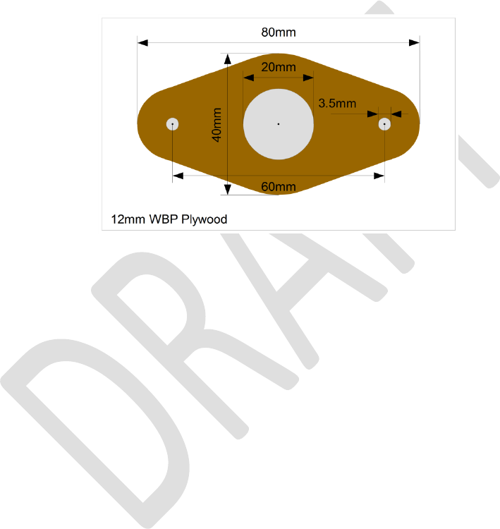
Type 2 Simulator – Build & Installation Guide 0.6
66
Magnet Mounting
The magneto-resistive sensor is triggered by a small rare-earth magnet mounted on the shroud of
the wheel, such that the magnet is opposite the centre of the Sensor Head (i.e., co-axial with the
2SS52M sensor IC) when the bell is at the bottom of its swing.
The magnet used is a N52 grade rare earth magnet, 20mm diameter x 10mm thick. The following
mounting is suggested for a permanent installation: The trigger magnet is mounted in a “flange” cut
from 12mm WBP plywood, which is then fixed to the shroud of the wheel using stainless steel
screws or double-sided tape.
The dimensions of the mounting flange are show in the following diagram:
Figure 59 – Magnet Mounting Dimensions
The magnet mountings are constructed as follows:
• The shape of the mounting is marked out on a piece of WBP plywood, 12mm thick. A paper
template may be printed out and stuck temporarily to the wood with glue or double sided
tape. A suitable template is available from the GitHub repository as a PDF, and should be
printed out full size with no scaling.
• The centre hole for the magnet is drilled out with a 20mm spade bit. This should be used in a
bench drill press, if available, so that the hole is reasonably accurately cut and the magnet
will be a close fit.
• If the mounting is to be fixed to the wheel with screws, the screw holes are also drilled. It is
easier to drill all the holes before cutting the mount to size.
• The mounting is then cut and sanded to shape, and the remains of the template removed.
Do not sand the inside of the central hole.
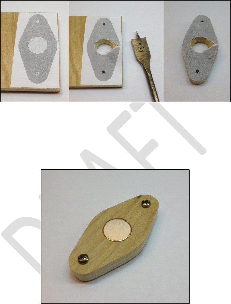
Type 2 Simulator – Build & Installation Guide 0.6
67
These steps are illustrated in the following series of pictures.
Figure 60 – Magnet Mounting Construction
The magnet is pushed into the central hole, and secured with a small amount of epoxy adhesive (e.g.
Araldite). The face of the magnet should be flush with the outer face of the mount, and note that for
the Honeywell sensor the polarity of the magnet is not important.
The following picture shows a completed magnet mounting, ready for painting.
Figure 61 – Completed Magnet Mounting
Care must be taken when handling the rare earth magnets, because they are both powerful and
brittle, and can strike a magnetic object with enough force to shatter the magnet. They are also
susceptible to corrosion, so must be painted or coated with a thin layer of epoxy.
Once painted the mounting can be fixed the wheel with pan head stainless steel self-tapping screws
3.5mm in diameter and 20mm – 25mm long; the screws should not protrude through the shroud of

Type 2 Simulator – Build & Installation Guide 0.6
68
the wheel. Alternatively, the mount can be secured with double-sided tape, provided the surface of
the wheel is sound and free from dust.
Infra-Red Sensors
The sensor is attached to the bell frame in a similar way to a magneto-resistive sensor, such that the
sensor masking tube is perpendicular to the face of the shroud of the wheel.
Reflector
The sensor requires a reflector mounted on the shroud of the wheel, such that the reflector is
opposite the Sensor Head when the bell is at the bottom of its swing.
The reflector is made from a short length of white reflective automotive styling tape, 25mm wide
(which may be obtained from a car spares shop), positioned directly opposite the sensor tube when
the bell is down.
Calibration
As supplied, most of the infra-red detector sensor modules have been found to draw approximately
55 – 60mA, much more than the specified 25mA, and were excessively sensitive. The small
calibration screw on the back end of the module may be used to reduce both the current
consumption and sensitivity of the detector.
A useful starting point for sensitivity adjustment has been found to be to reduce the sensitivity of
the sensor such that it does not trigger when placed perpendicular to a piece of grey card at a
distance of 90mm from the end of the detector. The multi-turn adjustment screw is turned anti-
clockwise until the indicator LED on the back of the module just goes out. This gives an effective
maximum trigger distance with the reflective tape of about 300mm. This also reduces the supply
current.
Fine adjustment of the sensor should then be carried out in the belfry for optimum sensitivity.
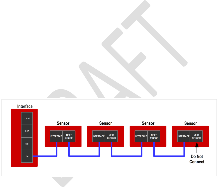
Type 2 Simulator – Build & Installation Guide 0.6
69
Cabling
Power/Data Cable
The Power/Data Cable runs between the Power Board and the Simulator Interface Board.
• The cable is a standard straight-through (not crossover) Cat5e or Cat6 Ethernet network
cable, with RJ45 connectors. These are available ready-made, for example from Farnell or
CPC.
• The maximum length of cable tested is 25m, although longer cables may be feasible.
• An example of a 25m cable is Farnell part number 2575533.
Sensor Cables
The sensors are also cabled back to the Simulator Interface using standard Cat5e or Cat6 network
cables.
• The cables are a standard straight-through (not crossover) Cat5e or Cat6 Ethernet network
cable, with RJ45 connectors. These are available ready-made, for example from Farnell or
CPC.
• The maximum tested length of a chain of four sensors is 20m, made up of 4 x 5m cables,
although longer cables may be feasible.
• An example of a 5m cable is Farnell part number 1734948.
Sensors are wired in a “daisy chain” fashion, with each chain consisting of a maximum of four
sensors. The wiring of one chain is illustrated in the following diagram.
Figure 62 – Sensor Daisy Chain
It is important to understand that there is no requirement to connect any particular sensor to any
specific bell, and no requirement that chains should consist of any particular number of sensors.
• The cabling should be arranged to suit the layout and constraints of the belfry.
• The relationship between Simulator Interface channels and bells will be managed in the
interface firmware. This is explained in a worked example later in this guide.
• There are obvious constraints for higher numbers of bells: A ring of 12 will require at least
three sensors on each chain, and a ring of 16 will require all four chains with four sensors
each.
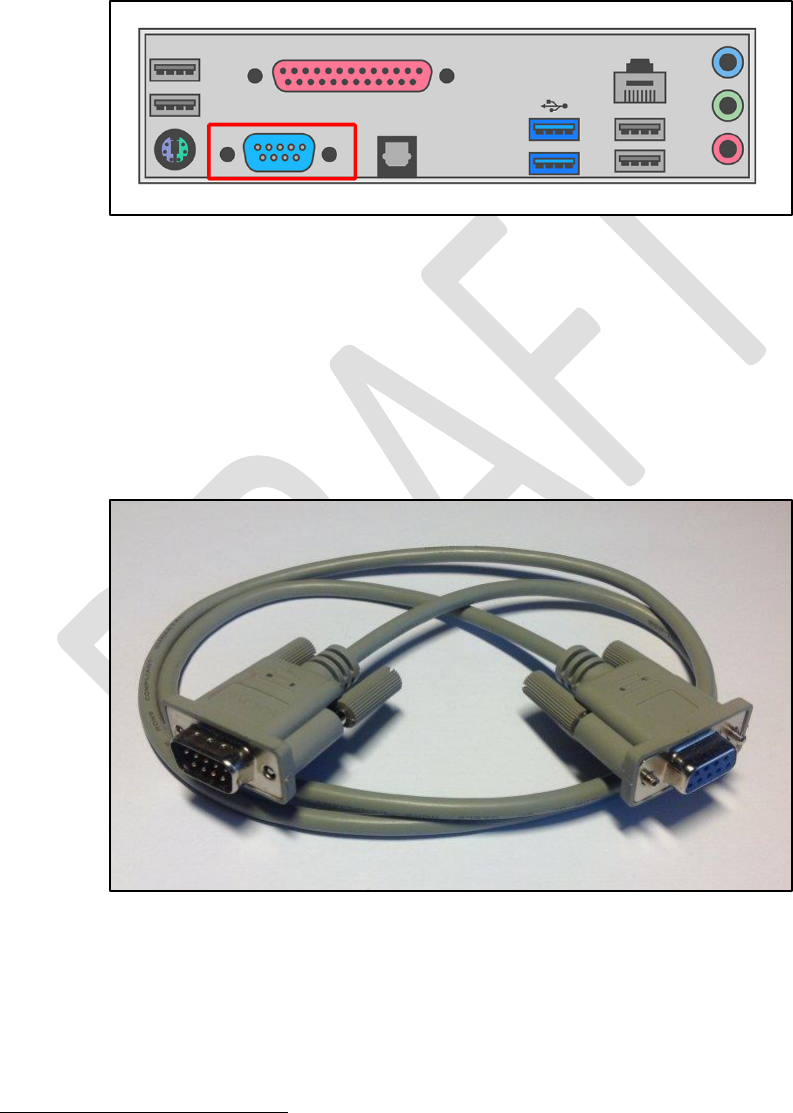
Type 2 Simulator – Build & Installation Guide 0.6
70
Computer Connection
The simulator Power Board is connected to the Simulator PC in the ringing room with a serial cable.
The type of cable required depends on the kind of serial port built into the PC.
9-Pin Serial Connector
The Simulator PC may be fitted with a 9-pin RS-232 serial or “COM” port, as illustrated in the
following diagram:
Figure 63 – 9-Pin Serial Port
This type of serial port is common on older computers, but not often found on newer models.
If the Simulator PC has a 9-pin serial port, use a 9-pin Female to 9-pin Male straight-through
29
serial
cable to connect the computer to the simulator interface. Examples of suitable cables are Farnell
part 2444240 (1.8m), CPC part CS24423 (1m), or CPC part CS24424 (2m).
A typical cable, with the connectors required, is illustrated in the following photograph:
Figure 64 – 9-Pin Serial Cable
If your computer has both a 9-pin serial port and USB ports, use the 9-pin serial port.
29
A “straight-through” cable has pin 1 wired to pin 1, pin 2 to pin 2, and so on. Do not use a “null modem”
cable, which has more complex internal wiring and is not suitable.
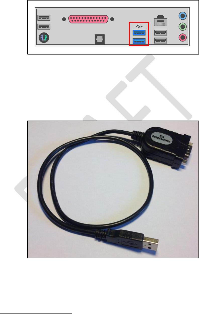
Type 2 Simulator – Build & Installation Guide 0.6
71
USB Connector
More modern computers are likely to be fitted only with USB ports, as illustrated in the following
diagram:
Figure 65 – PC USB Ports
In this case, use a USB-Serial adapter to connect the simulator Power Board to a spare USB port on
the Simulator PC. If necessary, a straight through serial cable as above can be used as an extension.
An example of a typical USB-Serial adapter is CPC part CS30877, illustrated in the following
photograph
30
. Note that an extension cable may be required if (as in this case) the adapter does not
have securing screws.
Figure 66 – USB to Serial Adapter
Install the drivers supplied with the adapter and identify the COM port number allocated (you will
need to know this later to configure your Simulator Software Package).
There is more information on USB-Serial adapters in the Technical Reference Guide.
30
If your computer has only “USB-C” or “USB 3” ports then you may require a different adapter.
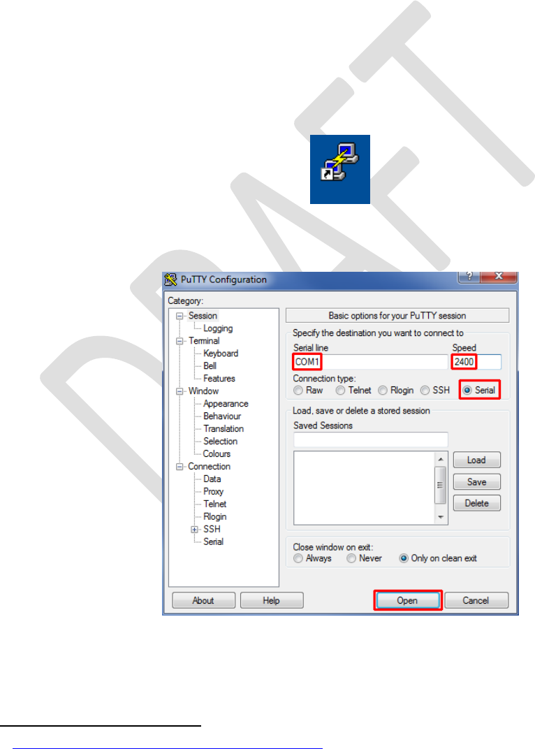
Type 2 Simulator – Build & Installation Guide 0.6
72
Interface Setup
The Type 2 Liverpool Simulator Interface is highly configurable, but most of the default settings
should be fine for most installations. There is detailed information about all the configuration
options in the Technical Reference Guide.
There are a couple of configuration options which you should set before using the simulator:
disabling unused sensor channels, and re-mapping sensors to bells. Configuration of the Simulator
Interface should only need to be done once. All settings are retained in non-volatile EEPROM when
the interface is powered off.
Connecting to the Interface
• On the Simulator PC, ensure that a Simulator Software Package (e.g. Abel) is not running.
Close the Simulator Software Package down if it is running.
• Download and install a serial terminal emulator package
31
. This manual assumes the use of
the Open Source PuTTY terminal emulator.
• Start the PuTTY terminal emulator by double-clicking the PuTTY icon on the desktop.
• Configure a Serial connection using the COM port number of the serial port (e.g. COM1),
running at 2400 bps, and then click Open. You should not need to change any other settings
in PuTTY.
Figure 67 – PuTTY Configuration Dialogue
31
http://www.chiark.greenend.org.uk/~sgtatham/putty/

Type 2 Simulator – Build & Installation Guide 0.6
73
Click on the PuTTY terminal window, then type “?” (question mark). There is no need to press
Enter. After a short pause the Simulator Interface will respond by displaying its current settings,
which may not be identical to these examples
32
.
Figure 68 – Display Interface Settings
Worked Example
The following worked example shows how to disable unused sensor channels, and re-map channels
when setting up the Simulator Interface. You should adapt the instructions in the worked example to
suit your installation.
Sensor Channels
Before configuring the interface, it is important to understand the difference between interface
sensor channels numbers, and numbers of the bells. The channel numbers are fixed as shown in the
diagram below: Channel 1 is always the first sensor on the first chain, channel 2 is always the second
sensor on the first chain, and so on up to channel 16.
32
The default PuTTY colour scheme is white (or coloured) text on a black background. In these examples this
has been reversed and reduced to black on white for better printing.
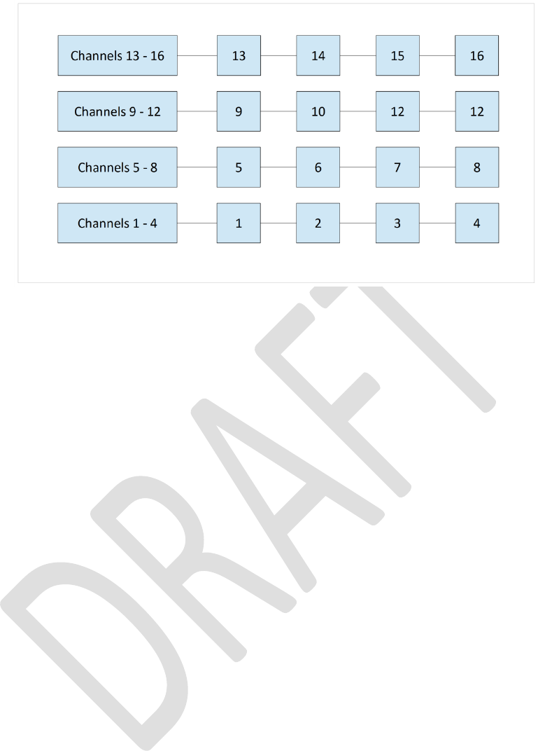
Type 2 Simulator – Build & Installation Guide 0.6
74
Figure 69 – Interface Channel Numbers
To re-iterate the guidance in the previous section, there is no requirement to connect any particular
sensor to any specific bell, and no requirement that chains should consist of any particular number
of sensors. The sensor cabling should be arranged to suit the layout and constraints of the belfry.
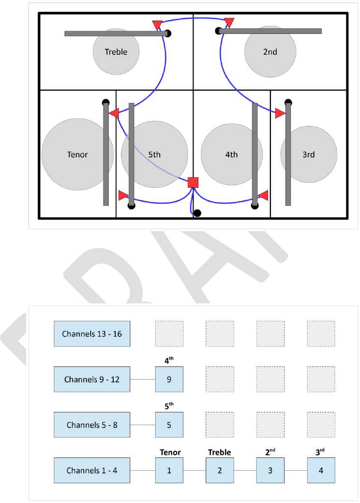
Type 2 Simulator – Build & Installation Guide 0.6
75
Example Installation
The diagram below shows the sensor cabling for a mythical ring of six. The cables between the
sensors and the interface have been routed as shown, to avoid the clock wires, chiming hammers,
rope chutes and all the other things which clutter up the belfry. This example is deliberately
convoluted to show how the interface settings can be configured.
Figure 70 – Example Sensor Cabling
As a result, the sensors on the bells are connected to the following channels. Channels 6, 7, 8, and 10
to 16 are not used.
Figure 71 – Example Channel Connections

Type 2 Simulator – Build & Installation Guide 0.6
76
These unused channels will be disabled on the simulator interface. There is no point scanning these
channels for sensor signals, as there are no sensors connected to them.
Figure 72 – Disabled Channels
Default Settings
Open a terminal session to the interface using PuTTY, as described above.
• The “?” command shows the default settings:
Figure 73 – Default Settings
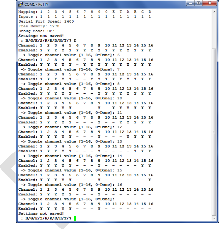
Type 2 Simulator – Build & Installation Guide 0.6
77
Disable Unused Channels
• To disable (or enable) channels, use the “E” command. There is no need to press Enter after
typing the “E”.
• Enter the number of each channel to be disabled, pressing Enter after each one. In the
example below, channels 6, 7, 8, and 10 to 16 are disabled.
• When you have finished, enter a zero (or just press Enter).
• The interface software will not allow you to disable all the sensors.
• These settings are not saved yet and will revert to the defaults if the interface power is
turned off. The settings will be saved later.
Figure 74 – Disabling Channels Example

Type 2 Simulator – Build & Installation Guide 0.6
78
Re-Map Channels to Bells
Although the mapping between the channel/sensor numbers and the real bell numbers can be
reconfigured in most Simulator Software Packages, it is less confusing if this is set in the simulator
interface.
In the example installation above, the interface channels are mapped to the real bells as follows:
Table 7 – Example Channel Mapping
Channel
Bell
1
6
2
1
3
2
4
3
5
5
9
4
• To re-map a channel to a real bell number, use the “R” command. There is no need to press
Enter after typing the “R”.
• Enter the number of each channel to be remapped, and press Enter.
• Then enter the number (or letter) of bell to which that sensor is attached, and press Enter.
The numbers and letters follow the usual ringing conventions, as shown in the table below:
Table 8 – Bell Numbers & Letters
Bells
Bell Numbers/Letters
1 to 9
1 – 9
10
0
11
E
12
T
13 to 16
A – D
Switches
W – Z
• Letters W, X, Y and Z are used in Abel switch configurations, and are not normally used.
More information on switches can be found in the Technical Reference Guide.
• Repeat for all the other channels to be re-mapped. In the example below, channels 5 is
already allocated to the 5th, so no re-mapping is needed.
• When you have finished, enter a zero (or just press Enter).
• The interface software will warn you if duplicate mapping are defined, but will not prevent
you from saving such a configuration
33
.
• These settings are not saved yet and will revert to the defaults if the interface power is
turned off. The settings will be saved later.
33
You may have a single interface serving both a ring of real bells and a set of training dumb bells, for example.
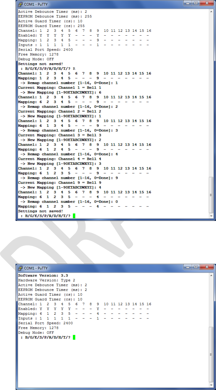
Type 2 Simulator – Build & Installation Guide 0.6
79
Figure 75 – Channel Re-Mapping Example
Save Settings
• Review your settings with the “?”command.
Figure 76 – Example Channel Connections
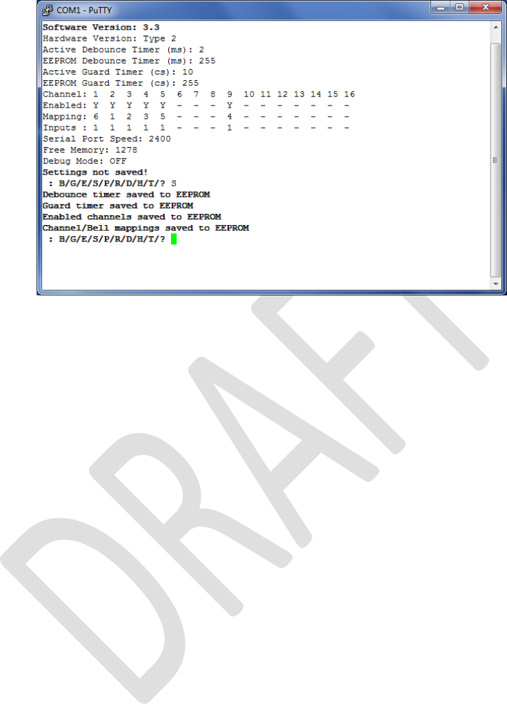
Type 2 Simulator – Build & Installation Guide 0.6
80
• Finally, save the settings using the “S” command, and then close the terminal window.
Figure 77 – Saving Interface Settings
Next Steps
You are now ready to move on to configure your chosen Simulator Software Package to work with
the simulator. Instructions for configuring the main Simulator Software Packages can be found in the
following guides:
• Configuring Abel Guide
• Configuring Beltower Guide
• Configuring Virtual Belfry Guide
If your Simulator Software Package is not listed above, please refer to the vendor’s instructions on
configuring their software to work with external sensors.

Type 2 Simulator – Build & Installation Guide 0.6
81
Licensing & Disclaimers
Documentation
All original manuals and other documentation (including PCB layout CAD files and schematics)
released as part of the Liverpool Ringing Simulator project
34
are released under the Creative
Commons Attribution-ShareAlike 4.0 International License (CC BY-SA),
35
which includes the following
disclaimers:
Unless otherwise separately undertaken by the Licensor, to the extent possible, the Licensor
offers the Licensed Material as-is and as-available, and makes no representations or
warranties of any kind concerning the Licensed Material, whether express, implied, statutory,
or other. This includes, without limitation, warranties of title, merchantability, fitness for a
particular purpose, non-infringement, absence of latent or other defects, accuracy, or the
presence or absence of errors, whether or not known or discoverable. Where disclaimers of
warranties are not allowed in full or in part, this disclaimer may not apply to You.
To the extent possible, in no event will the Licensor be liable to You on any legal theory
(including, without limitation, negligence) or otherwise for any direct, special, indirect,
incidental, consequential, punitive, exemplary, or other losses, costs, expenses, or damages
arising out of this Public License or use of the Licensed Material, even if the Licensor has been
advised of the possibility of such losses, costs, expenses, or damages. Where a limitation of
liability is not allowed in full or in part, this limitation may not apply to You.
Software
All original software released as part of the Liverpool Ringing Simulator project is released under the
GNU General Public Licence (GPL), Version 3
36
, and carries the following disclaimers:
This program is free software: you can redistribute it and/or modify it under the terms of the
GNU General Public License as published by the Free Software Foundation, either version 3 of
the License, or (at your option) any later version.
This program is distributed in the hope that it will be useful, but WITHOUT ANY WARRANTY;
without even the implied warranty of MERCHANTABILITY or FITNESS FOR A PARTICULAR
PURPOSE. See the GNU General Public License for more details.
34
http://www.simulators.org.uk
35
http://creativecommons.org/licenses/by-sa/4.0/
36
http://www.gnu.org/licenses/gpl-3.0.en.html

Type 2 Simulator – Build & Installation Guide 0.6
82
Acknowledgements
The Liverpool Ringing Simulator project relies extensively on work already undertaken by others,
notably David Bagley (developer of the Bagley MBI), Chris Hughes and Simon Feather (developers of
the Abel simulator software package), Derek Ballard (developer of the Beltower simulator software
package), Doug Nichols (developer of the Virtual Belfry simulator software package), and others.
Their invaluable contributions are hereby acknowledged. Sources used are referenced in the
footnotes throughout.
Thanks are also owed to the Ringing Masters and ringers of the following towers for their willingness
to be the crash test dummies of simulator design and testing.
• Liverpool Cathedral
• St George’s, Isle of Man
• St Mary, Chirk, Wrexham
• St John, Higham, Kent
• St Margaret, Crick, Northamptonshire
• St Mary & St Peter, Lois Weedon, Northamptonshire
Really Useful Box ® is a registered trademark of Really Useful Products Ltd.
