PA Series PowerStation User Guide 06692100
User Manual: PA Series
Open the PDF directly: View PDF ![]() .
.
Page Count: 76
- Manual Overview and Support Services
- Introducing the PA PowerStation
- Installing the PA PowerStation
- Maintaining and Troubleshooting the PA PowerStation
- System Configuration Files

CTC Parker Automation Phone:513-831-2340
50 W. TechneCenter Drive, Milford, Ohio 45150 Technical Support: 513-248-1714
A3-06692-100
PA Series User Guide
Copyright and Trademark Notice
Copyright © 2004 by CTC Parker Automation. All rights reserved. No part of this
publication may be reproduced, transmitted, transcribed, stored in a retrieval
system, in any form or by any means, mechanical, photocopying, recording or
otherwise, without the prior written consent of CTC Parker Automation.
While every precaution has been taken in the preparation of this manual, CTC
Parker Automation and the author assume no responsibility for errors or omissions.
Neither is any liability assumed for damages resulting from the use of the informa-
tion contained herein. All product and company names are trademarks of their
respective companies and licenses.
The following products are copyright their respective owners: Microsoft,
Microsoft Windows, Datalight ROM-DOS, SanDisk, SanDisk ImageMate, IBM,
Lantastic, and Gunk.
Product Warranty Information
CTC Parker Automation provides top quality products through rigid testing and the
highest quality control standards. However, should a problem occur with your
hardware or with the software protection key, CTC’s standard product warranty
covers these items for 15 months from the date of shipment from CTC. Exceptions
appear below:
• PowerStation backlight bulbs have a 90-day warranty.
• Third-party products, such as bus cards, carry the manufacturer’s specified
warranty.
• For all displays, image retention (burn-in) is not covered by warranty.
• Software revisions that occur within 60 days after purchase are available
under warranty upon request. Please review the Interact License Agree-
ment for additional software warranty information.
Should you have any questions about your application or need technical assistance,
please call CTC’s Product Technical Support department at 513-248-1714, 8:00
a.m. to 5:00 p.m., Eastern Time. You may call this same number after hours for
emergency assistance. See Customer Support Services on page 5 of this manual for
more information about CTC’s support products and services.

Table of Contents
PA PowerStation User Guide i
Chapter 1 Manual Overview and Support Services . . . . . . . 1
Using this Manual. . . . . . . . . . . . . . . . . . . . . . . . . . . . . . . . . . . . . . . . 2
Documentation Components . . . . . . . . . . . . . . . . . . . . . . . . . . . . . . . 3
Software Components . . . . . . . . . . . . . . . . . . . . . . . . . . . . . . . . . . . . 3
Getting Started . . . . . . . . . . . . . . . . . . . . . . . . . . . . . . . . . . . . . . . . . . 3
Before You Begin. . . . . . . . . . . . . . . . . . . . . . . . . . . . . . . . . . . . . . . . . . . 3
Installing the PowerStation . . . . . . . . . . . . . . . . . . . . . . . . . . . . . . . . . . . 4
Downloading Applications and Projects. . . . . . . . . . . . . . . . . . . . . . . . . . 4
Documentation Standards . . . . . . . . . . . . . . . . . . . . . . . . . . . . . . . . . 4
ISO Symbols . . . . . . . . . . . . . . . . . . . . . . . . . . . . . . . . . . . . . . . . . . . . . . 5
Customer Support Services . . . . . . . . . . . . . . . . . . . . . . . . . . . . . . . . 5
Product Technical Support . . . . . . . . . . . . . . . . . . . . . . . . . . . . . . . . . . . 5
Technical Training . . . . . . . . . . . . . . . . . . . . . . . . . . . . . . . . . . . . . . . . . . 6
Chapter 2 Introducing the PA PowerStation. . . . . . . . . . . . . 7
Specifications . . . . . . . . . . . . . . . . . . . . . . . . . . . . . . . . . . . . . . . . . . . 8
Display Specifications . . . . . . . . . . . . . . . . . . . . . . . . . . . . . . . . . . . . . . . 8
PA05S 5" Color . . . . . . . . . . . . . . . . . . . . . . . . . . . . . . . . . . . . . . . . . 8
. . . . . . . . . . . . . . . . . . . . . . . . . . . . . . . . . . . . . . . . . . . . . . . . . . . . . . . . . 8
PA06S 6" Color . . . . . . . . . . . . . . . . . . . . . . . . . . . . . . . . . . . . . . . . . 8
PA08S & PA08T 8" Color . . . . . . . . . . . . . . . . . . . . . . . . . . . . . . . . . 9
PA10T 10" Color . . . . . . . . . . . . . . . . . . . . . . . . . . . . . . . . . . . . . . . . 9
. . . . . . . . . . . . . . . . . . . . . . . . . . . . . . . . . . . . . . . Physical Specifications9
Environmental Specifications. . . . . . . . . . . . . . . . . . . . . . . . . . . . . . . . . 10
Electrical Specifications. . . . . . . . . . . . . . . . . . . . . . . . . . . . . . . . . . . . . 11
Testing Specifications . . . . . . . . . . . . . . . . . . . . . . . . . . . . . . . . . . . . . . 12
Faceplate Chemical Resistance . . . . . . . . . . . . . . . . . . . . . . . . . . . . . . 13
Available Connectors . . . . . . . . . . . . . . . . . . . . . . . . . . . . . . . . . . . . 14
Serial Ports . . . . . . . . . . . . . . . . . . . . . . . . . . . . . . . . . . . . . . . . . . . . . . 14

Table of Contents
ii PA PowerStation User Guide
Settings and Pinouts for COM1 and COM2 . . . . . . . . . . . . . . . . . . .15
Transferring Files from a PC to the PA PowerStation . . . . . . . . . . .18
Connecting a Serial Mouse . . . . . . . . . . . . . . . . . . . . . . . . . . . . . . .19
Connecting to a Serial Printer . . . . . . . . . . . . . . . . . . . . . . . . . . . . .20
Keyboard/Mouse Port. . . . . . . . . . . . . . . . . . . . . . . . . . . . . . . . . . . . . . .22
Connecting a PS/2 Mouse . . . . . . . . . . . . . . . . . . . . . . . . . . . . . . . .22
Ethernet Port . . . . . . . . . . . . . . . . . . . . . . . . . . . . . . . . . . . . . . . . . . . . .22
CompactFlash . . . . . . . . . . . . . . . . . . . . . . . . . . . . . . . . . . . . . . . . . . . .23
. . . . . . . . . . . . . . . . . . . . . . . . . . . . . . . . . . . . . . . . . . . . . . . . . . . . . . . .23
Drive Definition and Memory . . . . . . . . . . . . . . . . . . . . . . . . . . . . . . .24
Memory Guidelines. . . . . . . . . . . . . . . . . . . . . . . . . . . . . . . . . . . . . . . . .24
Replacement Components . . . . . . . . . . . . . . . . . . . . . . . . . . . . . . . .25
CompactFlash Card . . . . . . . . . . . . . . . . . . . . . . . . . . . . . . . . . . . . . . . .25
SDRAM. . . . . . . . . . . . . . . . . . . . . . . . . . . . . . . . . . . . . . . . . . . . . . . . . .25
Touchscreen. . . . . . . . . . . . . . . . . . . . . . . . . . . . . . . . . . . . . . . . . . . . . .25
Backlight Bulb. . . . . . . . . . . . . . . . . . . . . . . . . . . . . . . . . . . . . . . . . . . . .25
Replaceable Fuse. . . . . . . . . . . . . . . . . . . . . . . . . . . . . . . . . . . . . . . . . .25
Optional Components . . . . . . . . . . . . . . . . . . . . . . . . . . . . . . . . . . . .26
AC Power Supply . . . . . . . . . . . . . . . . . . . . . . . . . . . . . . . . . . . . . . . . . .26
Chapter 3 Installing the PA PowerStation. . . . . . . . . . . . . .27
Selecting a Location. . . . . . . . . . . . . . . . . . . . . . . . . . . . . . . . . . . . . .28
Class I, Division 2 Guidelines . . . . . . . . . . . . . . . . . . . . . . . . . . . . . . . . .28
Environmental Guidelines. . . . . . . . . . . . . . . . . . . . . . . . . . . . . . . . . . . .28
Touchscreen Considerations . . . . . . . . . . . . . . . . . . . . . . . . . . . . . .28
Electrical Guidelines . . . . . . . . . . . . . . . . . . . . . . . . . . . . . . . . . . . . . . . . 29
Field Terminal Wiring Requirements . . . . . . . . . . . . . . . . . . . . . . . .29
Temperature Guidelines . . . . . . . . . . . . . . . . . . . . . . . . . . . . . . . . . . . . .29
Enclosure Guidelines . . . . . . . . . . . . . . . . . . . . . . . . . . . . . . . . . . . . . . . 29

Table of Contents
PA PowerStation User Guide iii
AC Power Guidelines. . . . . . . . . . . . . . . . . . . . . . . . . . . . . . . . . . . . . . . 29
Preparing for Installation. . . . . . . . . . . . . . . . . . . . . . . . . . . . . . . . . . 31
Creating the Cutout . . . . . . . . . . . . . . . . . . . . . . . . . . . . . . . . . . . . . . . . 31
Create a Cutout. . . . . . . . . . . . . . . . . . . . . . . . . . . . . . . . . . . . . . . . 31
Preparing a Location for the AC Power Supply . . . . . . . . . . . . . . . . . . . 32
Installing the PA PowerStation . . . . . . . . . . . . . . . . . . . . . . . . . . . . . 33
Mounting the PA PowerStation . . . . . . . . . . . . . . . . . . . . . . . . . . . . . . . 33
. . . . . . . . . . . . . . . . . . . . . . . . . . . . . . . . . . . . . . . . . . . . . . Starting Up
the PA PowerStation . . . . . . . . . . . . . . . . . . . . . . . . . . . . . . . . . . . . . . . 37
Chapter 4 Maintaining and Troubleshooting the PA
PowerStation . . . . . . . . . . . . . . . . . . . . . . . . . . . . . . . . . . . . . 39
Installing and Replacing Parts . . . . . . . . . . . . . . . . . . . . . . . . . . . . . 40
Electrostatic Discharge Precautions . . . . . . . . . . . . . . . . . . . . . . . . . . . 40
Replacing the Fuse . . . . . . . . . . . . . . . . . . . . . . . . . . . . . . . . . . . . . . . . 41
BIOS Setup. . . . . . . . . . . . . . . . . . . . . . . . . . . . . . . . . . . . . . . . . . . . 42
Removing the CTC Splash Screen . . . . . . . . . . . . . . . . . . . . . . . . . . . . 42
Maintaining the Touchscreen . . . . . . . . . . . . . . . . . . . . . . . . . . . . . . 43
Cleaning the Touchscreen. . . . . . . . . . . . . . . . . . . . . . . . . . . . . . . . . . . 43
Calibrating the Touchscreen . . . . . . . . . . . . . . . . . . . . . . . . . . . . . . . . . 43
Using the MachineShop Shell Calibration Utility . . . . . . . . . . . . . . . 44
Adjusting the Contrast . . . . . . . . . . . . . . . . . . . . . . . . . . . . . . . . . . . . . . 45
Adjusting the Contrast (For STN Units Only) . . . . . . . . . . . . . . . . . 46
Using the Compact Flash Card . . . . . . . . . . . . . . . . . . . . . . . . . . . . 47
Replacing the Compact Flash . . . . . . . . . . . . . . . . . . . . . . . . . . . . . . . . 47
Reinstalling the PowerStation Utilities . . . . . . . . . . . . . . . . . . . . . . . . . . 48
Restoring a CompactFlash Card. . . . . . . . . . . . . . . . . . . . . . . . . . . 48
Writing to the CompactFlash Card . . . . . . . . . . . . . . . . . . . . . . . . . 48
Reformatting the CompactFlash Card. . . . . . . . . . . . . . . . . . . . . . . 49
Modifying the AUTOEXEC.BAT File. . . . . . . . . . . . . . . . . . . . . . . . . 51

Table of Contents
iv PA PowerStation User Guide
Configuring the Ethernet Interface . . . . . . . . . . . . . . . . . . . . . . . . . . .53
Resolving Problems . . . . . . . . . . . . . . . . . . . . . . . . . . . . . . . . . . . . . .55
Resolving Problems when Starting Up . . . . . . . . . . . . . . . . . . . . . . . . . .56
Resolving Problems with the Touchscreen . . . . . . . . . . . . . . . . . . . . . .57
Resolving Problems after Start Up. . . . . . . . . . . . . . . . . . . . . . . . . . 58
Replacing the SDRAM. . . . . . . . . . . . . . . . . . . . . . . . . . . . . . . . . . . .61
System Configuration Files . . . . . . . . . . . . . . . . . . . . . . . . . . . .65
System Configuration Files . . . . . . . . . . . . . . . . . . . . . . . . . . . . . . . .66
CONFIG.SYS File. . . . . . . . . . . . . . . . . . . . . . . . . . . . . . . . . . . . . . . . . .66
AUTOEXEC.BAT File . . . . . . . . . . . . . . . . . . . . . . . . . . . . . . . . . . . . . . .67

Chapter 1
Manual Overview and
Support Services
Thank you for purchasing a PA PowerStation. The PA
PowerStation is a rugged, compact PC that is designed to be used
as an industrial operator interface.
The PA PowerStation is available in five display configurations:
5", 6", 7.7", 8", and 10". It also has an all-in-one PC board with a
Serial port and an Ethernet port. The PA PowerStation’s PC
architecture allows you to run CTC’s MachineShop software.
Please take time to review this manual and the other
documentation included with the PA PowerStation before
operating the unit.
Chapter Contents
Using this Manual 2
Documentation Components 3
Software Components 3
Getting Started 3
Documentation Standards 4
Customer Support Services 5

Using this Manual Chapter 1: Manual Overview and Support Services
2PA PowerStation User Guide
Using this
Manual
This manual is designed to help you set up and use your PA
PowerStation. The manual lists the PowerStation’s specifications and
describes its replacement and optional components. It also explains
how to install the unit, how to maintain the unit in good condition, and
how to solve common problems that may occur in operation.
This manual is divided into the following chapters:
Chapter 1 — Manual Overview and Support Services: Presents an
overview of this manual, the other documentation and software
provided with the PA PowerStation, and the steps necessary to get
your PowerStation up and running. This chapter also describes CTC’s
customer support services.
Chapter 2 — Introducing the PA PowerStation: Describes the PA
PowerStation’s specifications and the ports available to connect the
PowerStation to other devices and to a power source. This chapter also
describes the PowerStation’s drive definitions and the unit’s
replacement and optional components.
Chapter 3 — Installing the PA PowerStation: Explains how to
install the PA PowerStation in a control enclosure and how to start up
the unit.
Chapter 4 — Maintaining and Troubleshooting the PA
PowerStation: Explains how to install replacement parts, how to
maintain the PA PowerStation, and how to solve problems that may
occur during operation.
Appendix A—System Configuration Files: This section includes a
complete listing of the CONFIG.SYS and AUTOEXEC.BAT files.

PA PowerStation User Guide 3
Chapter 1: Manual Overview and Support Services Documentation Components
Documentation
Components
The PA PowerStation documentation set contains all the information
you need to configure, install, and use the PA PowerStation. The PA
PowerStation documentation set is described below.
Release Notes - This document is provided whenever there is
important information about the PA PowerStation that does not appear
in this manual. Be sure to read any available release notes before
installing or operating the unit.
PowerStation PA Series User Guide - This is the document you are
reading. It provides detailed information about the PA PowerStation
and describes how to configure, install, and use the unit. Please read
this manual in its entirety before operating the unit.
PA PowerStation Template - This document is a full-size template of
the PA PowerStation that you can use to prepare the location where you
want to install the unit.
Software
Components
CTC pre-loads each PA PowerStation with Datalight’s ROM-DOS
operating system, the MachineShop Shell, and necessary utilities so
that you can run the PowerStation immediately upon its arrival at your
facility. CTC also provides backup copies of PowerStation and
MachineShop software on the MachineShop Installation CD shipped
with the PowerStation.
Getting Started Now that you have opened the PA PowerStation package, you are
ready to unpack the unit, develop an application, and install the
PowerStation in a permanent location. This section provides an
overview of these activities. Additional information is available in the
remaining chapters of this manual.
Before You Begin Before you begin operating the PA PowerStation, please complete the
following steps:
1. Unpack the PowerStation, and verify that you have received all the
components you ordered.
2. Fill out the product registration card, and return it to CTC.
3. Backup the CTC software that was pre-installed on your unit using
the Windows File Manager/Explorer or the ROM-DOS Diskcopy
command.

Documentation Standards Chapter 1: Manual Overview and Support Services
4PA PowerStation User Guide
Installing the
PowerStation When you finish unpacking the PowerStation and developing an
application, you are ready to install the unit in a permanent location.
See Chapter 3 Installing the PA PowerStation on page 33 for
complete installation instructions.
Downloading
Applications and
Projects
The PA PowerStation is a runtime-only system, which means that you
must develop your applications and projects on a development PC and
download the application to the PowerStation.
Note Throughout this manual, all references to “development PC” or
“development system” refer to the computer you use to develop
applications.
See the documentation that came with your development software for
information about how to develop your applications or projects and
download them to the PowerStation.
Documentation
Standards
As you read this manual, you will notice that it uses the following
documentation standards:
1. Important terms are shown in bold.
2. Text to be entered from the keyboard is shown in Courier font.
3. Buttons, menu titles, and keyboard keys are shown in Initial Caps.
4. Indented paragraphs denote one of the following:
•Note - Describes alternative approaches or issues you should
be aware of while using a particular function.
•Important - Contains information that you need to pay
particular attention to while reading. Follow this information
to save development time and minimize problems.
•Warning - Contains information on safety issues. Follow this
information to prevent equipment damage or personal injury.

PA PowerStation User Guide 5
Chapter 1: Manual Overview and Support Services Customer Support Services
ISO Symbols This symbol is the International Standards Organization (ISO) symbol
for Caution (ISO 3864 No. B.3.1). This symbol denotes information
that could affect operation of the PowerStation if the information is not
properly followed.
This symbol is the ISO symbol for Caution—risk of electrical shock
(ISO 3864 No B.3.6). This symbol denotes information that could
cause personal injury from electrical shock or damage to equipment if
the information is not properly followed.
Customer
Support
Services
CTC welcomes your thoughts and suggestions on our products and
services. You can contact CTC by telephone, email, or fax. You can
also visit CTC on the World Wide Web to learn the latest about our
hardware, software, and customer support services.
• Telephone: 513-831-2340
• Fax: 513-831-5042
• E-mail: sales@ctcusa.com or support@ctcusa.com
• World Wide Web: http://www.ctcusa.com
CTC recognizes that every customer and every application has
different support needs, so CTC offers a variety of support services
designed to meet these needs. CTC offers two types of customer
support services:
• Product Technical Support
• Technical Training
Product Technical
Support The Product Technical Support department welcomes any question
that might arise as you develop or run your applications. We offer
complimentary support for all customers, including end users, original
equipment manufacturers (OEM), system integrators, or distributors.
If you have a question about the PA PowerStation, be sure to complete
the following steps:
1. Check any release notes shipped with the unit. These notes provide
important information about the PowerStation.
2. Consult the PowerStation documentation and other printed
materials included with the PowerStation.

Customer Support Services Chapter 1: Manual Overview and Support Services
6PA PowerStation User Guide
3. Review Chapter 4 of this manual, Maintaining and
Troubleshooting the PA PowerStation on page 39.
If you cannot find a solution using one of the above sources, contact
our Product Technical Support department at 513-248-1714, 8:00 a.m.
to 5:00 p.m., Eastern Time. You can call this same number after hours
for emergency assistance.
Technical Training CTC offers training on all of our products, either at CTC in our state-
of-the-art training facility, or at your site.
You can contact the Training Coordinator by telephone or e-mail:
• Telephone: 1-800-233-3329
• E-mail: training@ctcusa.com
You can view a current technical training schedule at our website,
http://www.ctcusa.com

Chapter 2
Introducing the PA
PowerStation
The PA PowerStation is designed to give you an operator interface
solution that is powerful, cost-effective, and very easy to use.
In this chapter, you will learn about the PA PowerStation’s
specifications, available connectors, and its drive definitions and
memory. The chapter also describes the PowerStation’s
replacement and optional components.
Chapter Contents
Specifications 8
Available Connectors 14
Drive Definition and Memory 24
Replacement Components 25
Optional Components 26
Specifications Chapter 2: Introducing the PA PowerStation
8PA PowerStation User Guide
Specifications This section describes important specifications for the PA
PowerStation. Please familiarize yourself with these specifications
before operating the unit.
Display
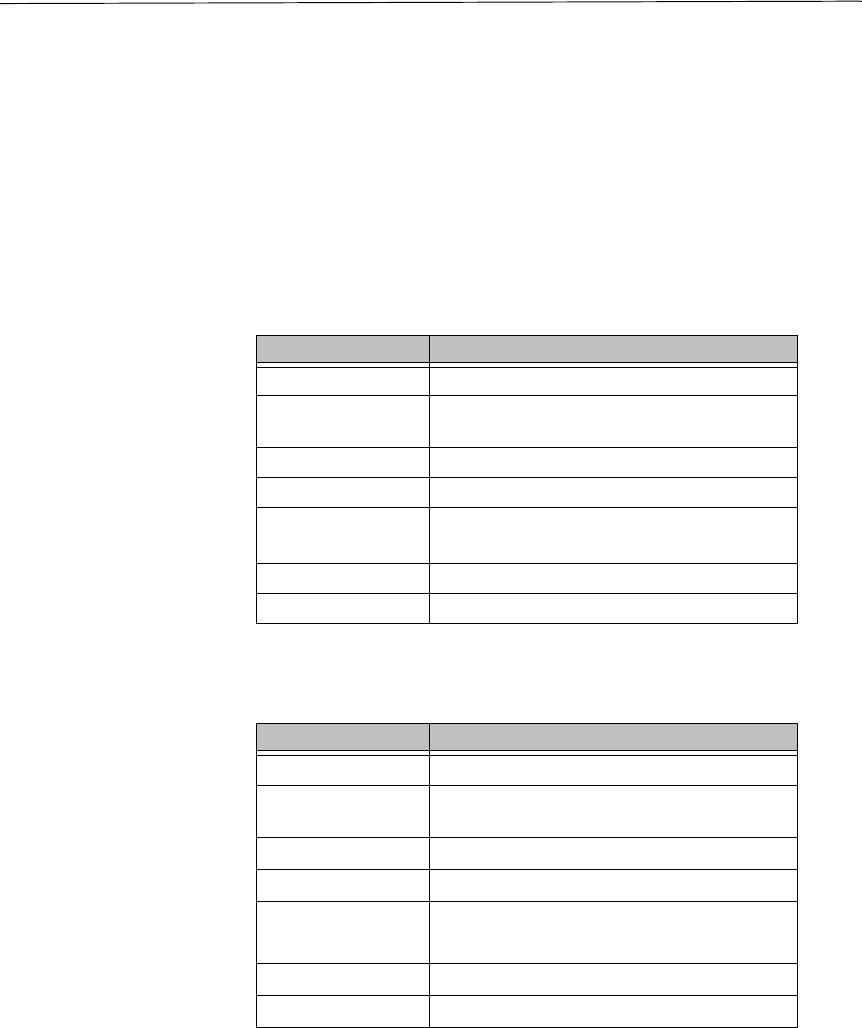
Specifications Display specifications include the type of monitor, size, resolution,
and other display properties. These specifications are shown in the
following tables. There is one table for each display size: 5", 6", 8",
and 10".
PA05S 5" Color
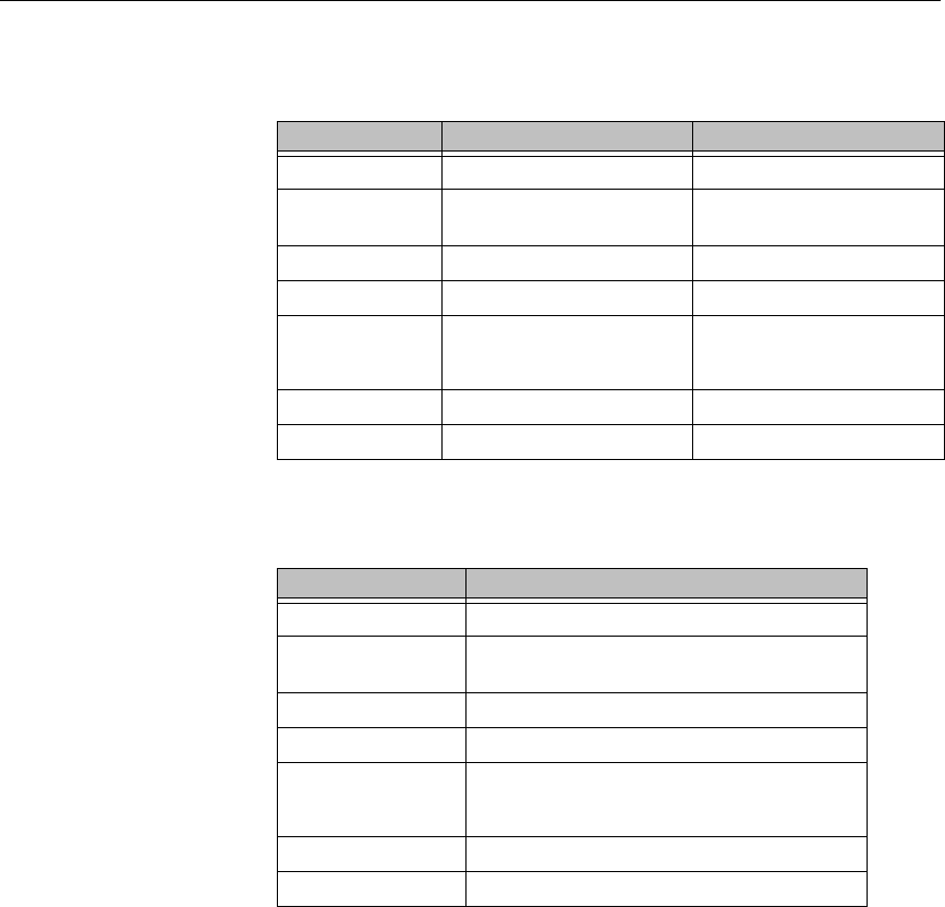
PA06S 6" Color
Property Description
Type Passive Color STN
Display Diagonal
Size 4.7”
Resolution QVGA (320 x 240)
Brightness 160 NITS
Viewing Angle U/D = 20/30 deg
L/R = 50/50 deg
Bulb Life 54,000 hours
Adjustments External Rear Contrast
Table 2-1: 5" Color Display
Property Description
Type Passive Color STN
Display Diagonal
Size 5.7"
Resolution QVGA (320 x 240)
Brightness 350 NITS
Viewing Angle U/D = 20-35 deg
L/R = 50/50 deg
Bulb Life 75,000 hours
Adjustments External Rear Contrast
Table 2-2: 6" Color Display
Chapter 2: Introducing the PA PowerStation Specifications
PA PowerStation User Guide 9
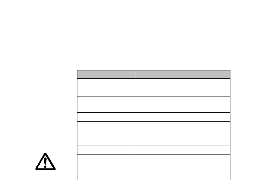
PA08S & PA08T 8" Color
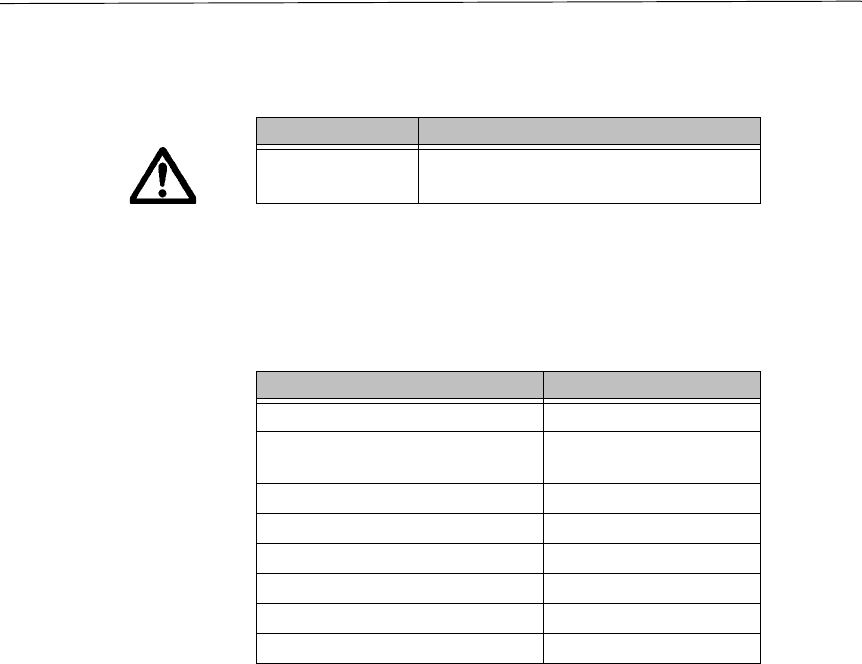
PA10T 10" Color
Physical
Specifications Physical specifications include the PowerStation’s CPU, memory
specifications, display types, storage capacity, and other physical
characteristics. These specifications are shown in Physical
Property PA08S Description PA08T Description
Type Passive Color STN Active Color TFT
Display Diago-
nal Size 7.7" 8.0"
Resolution VGA (640 x 480) VGA (640 x 480)
Brightness 120 NITS 285 NITS
Viewing Angle U/D = 30/50 deg
L/R = 50/50 deg
U/D = 65/55 deg
L/R = 65/65 deg
Bulb Life 40,000 hours 20,000 hours
Adjustments External Rear Contrast n/a
Table 2-3: 8" Color Display
Property Description
Type Active Color TFT
Display Diagonal
Size 10.4"
Resolution VGA (640 x 480)
Brightness 200 NITS
Viewing Angle U/D = 40/70 deg
L/R = 45/45 deg
Bulb Life 50,000 hours
Adjustments n/a
Table 2-4: 10" Color Display

Specifications Chapter 2: Introducing the PA PowerStation
10 PA PowerStation User Guide
Specifications.
Environmental
Specifications Even though the PA PowerStation is built to withstand harsh
environments, limit the PowerStation’s exposure to adverse conditions
such as dust, oil, moisture, and corrosive vapors to minimize
maintenance and repair costs.
Category Specifications
Operating Sys-
tem Datalight ROM-DOS
CPU 200 MHz X86 instruction set compatible proces-
sor
Memory 32MB PC100/PC133 SDRAM
144 Pin SODIMM Socket
BIOS Award 256KB Flash
Storage 32MB CompactFlash, Type 2 Socket
I/O Ports • 2 9-pin serial ports (16550 compatible)
• 1 9-pin RS232
• 1 9-pin RS232/422/485 (configurable)
• 1 RJ45 Ethernet connector; Intel 82551ER 10/
100 Base-T controller
Dimensions
H x W x D For the 5” and 6”:
• 6.0”H x 7.4”W x 2.3”D
For the 8”:
• 7.6”H x 10.2”W x 2.2”D
For the 10”:
• 11.0”H x 13.8”W x 3.2”D
Weight For the 5” and 6”:
•2.1 lbs
For the 8”:
•4.1 lbs
For the 10”:
•8.4 lbs.
Keyboard 1 PS/2 miniDIN
Mouse 1 PS/2 miniDIN
Touchscreen Analog Resistive
Audible Piezoelectric Beeper
Table 2-5: Physical Specifications
Chapter 2: Introducing the PA PowerStation Specifications
PA PowerStation User Guide 11
Remember that the temperature within a protective enclosure is
generally higher than the external temperature. Thus, if the PA
PowerStation is operating inside an enclosure at temperature levels
above its rated ambient temperature, you must cool the enclosure.The
PowerStation conforms to the environmental specifications listed in
Environmental Specifications Chart.
Electrical
Specifications The PA PowerStation’s power supply automatically detects the input
voltage level and adjusts accordingly. However, always use reliable
sources of power, and isolate all communication cables from AC
power lines to enhance noise immunity.
If possible, locate the PA PowerStation away from machinery that
produces intense electrical noise (arc welders, etc.). Otherwise, isolate
the input power to the PowerStation from the equipment generating
electrical noise.
The PA PowerStation’s electrical specifications appear in Electrical
Category Specifications
Operating
Temperature 32 to 122oF (0 to 50oC) ambient
(air temp. outside of backshell)
Storage
Temperature -4 to 140oF (-20 to 60oC)
Relative Humidity 0% to 95% non-condensing
Shock Rating • 10g peak; 11ms (operating)
• 30g peak; 11ms (non-operat-
ing)
Operating Vibration • 5-500Hz: 1G RMS random
Faceplate
Design NEMA 4/4X Environment
Warning: The PowerStation is rated
NEMA 4 only if it is installed in a NEMA 4-
rated enclosure.
Table 2-6: Environmental Specifications Chart
Specifications Chapter 2: Introducing the PA PowerStation
12 PA PowerStation User Guide
Specifications Chart.
Caution Do not apply AC power to the unit or damage may occur.
Testing
Specifications The PA PowerStation conforms to the testing specifications listed in
Testing Specifications Chart.
Category Specifications
Input voltage 12/24 VDC @ 18W
(Range: min 11 VDC, max 28 VDC)
Table 2-7: Electrical Specifications Chart
Test Specification
Showering arc NEMA showering arc
Surge withstanding capaci-
tance EN61000-4-5
ESD requirements EN61000-4-2
Operating temperature IEC 68-2-1
Electrical fast transient EN61000-4-4
Operating vibration IEC 68-2-6
Mechanical shock IEC 68-2-27
Random vibration MIL-STD-8100
Table 2-8: Testing Specifications Chart

Chapter 2: Introducing the PA PowerStation Specifications
PA PowerStation User Guide 13
Faceplate Chemical
Resistance The touchscreen of the PA PowerStation is resistant to the chemicals
listed in Chemical Resistance Chart.
Important Sustained exposure to brake fluid or Gunk® brand degreaser
can cause damage to monitor materials.
All PA PowerStation surfaces exposed outside your enclosure are
resistive to the following chemicals:
Touchscreen Chemical Resistance
Acetone Sulfuric Acid 10% Motor oil
MEK Hydrochloric Acid
10% Gasoline
Toluene Acetic Acid 10% Machine oil
Methylene Chlo-
ride Phosphoric Acid Salad oil
Isopropyl
Alcohol
Sodium Hydroxide
10% Silicone
Xylene Carbon Tetrachlo-
ride Silicone
grease G31
Hexane Potassium Hydrox-
ide Kerosene
Butyl Cellosolve Ammonia Water
10% Gas oil
Cyclohexanone Sodium Chloride
26% Silicone oil
Trichloroethylene Zinc Chloride 81% Engine oil
Ethanol Cottonseed Oil Cleanser
Methanol Glycerin
Nitric Acid 10% Grease
Table 2-9: Chemical Resistance Chart
• Commercial glass cleaners • Silicone based lubricant
• Motor oil • Alcohol (ethyl, methyl)
• Ammonia (10% dilute solu-
tion) • Automatic transmission
fluid
• Diesel fuel • Hydraulic fluid
• Gasoline (leaded, unlead-
ed)

Available Connectors Chapter 2: Introducing the PA PowerStation
14 PA PowerStation User Guide
Available
Connectors
All PA PowerStations have two serial ports, two PS/2 keyboard/mouse
ports, an Ethernet port, and a Compact Flash connector. See the PA
PowerStation CD for dimensional drawings and a diagram to locate
the components.
Serial Ports The PA PowerStation has two serial ports that you can use to
communicate with external devices at baud rates of up to 115 Kbaud.
The COM1 port supports RS-232, while COM2 supports RS-232, RS-
422, and RS-485 communication standards.
The communication standard you select for COM2 depends upon the
distance between the PA PowerStation and the controller, as well as
the communication standards that the controller supports. Use a
standard DB9 connector for communicating with this port.
Note If you are using RS-232 communications, the length of the
serial cable should not exceed 50 feet (15 meters).
RS-422 and RS-485 communications offer greater noise immunity
than RS-232. These standards increase the maximum cable length to
4,000 feet (1,200 meters).
RS-422 communications are full-duplex (send and receive
simultaneously), while RS-485 communications are half-duplex (send
or receive).
For either configuration, be careful not to connect any wires to unused
connector pins. If you are using CTC’s MachineShop software,
information on the specific connection required for the Interact drivers
you will use is located in the Help file associated with the driver.

Chapter 2: Introducing the PA PowerStation Available Connectors
PA PowerStation User Guide 15
Settings and Pinouts for COM1 and COM2
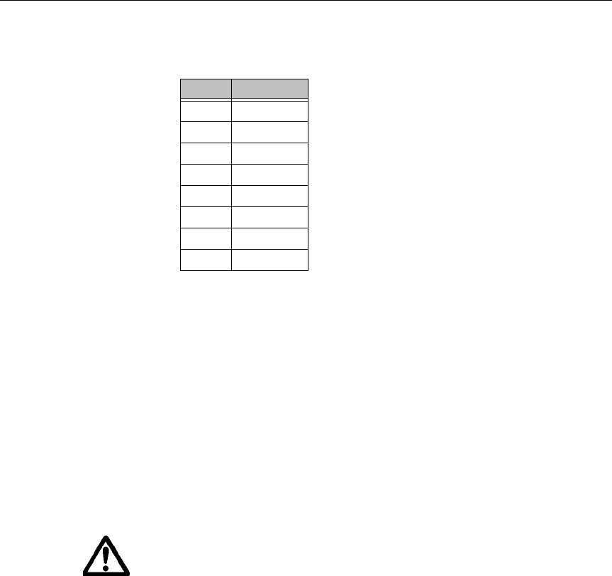
If you need to make a cable for communicating with COM1, COM1
Pinouts shows the pinouts and signal information for this port.
Pin# Signal
1 DCD, data carrier detect
2 RXD, received data
3 TXD, transmitted data
4 DTR, data terminal ready
5 Signal ground
6DSR
7 RTS, request to send
8 CTS, clear to send
9RI
Table 2-10: COM1 Pinouts

Available Connectors Chapter 2: Introducing the PA PowerStation
16 PA PowerStation User Guide
If you need to make a cable for communicating with COM2, COM2
Pinouts shows the pinouts and signal information for this port.
If you need to make a cable for communicating with COM2, you may
need to set the DIP switch settings.
COM2 is set to the RS-485 protocol by default. To change COM2 to
the RS-232 or RS-422 protocol, you must change the COM2 DIP
switch settings.
The DIP switch for COM2 is located on the side of the PA
Pin# RS-232
Signal RS-422
Signal RS-485
Signal
1 DCD, data
carrier detect TXD-, trans-
mitted data - TXD-, trans-
mitted data -
2RXD, re-
ceived data TXD+, trans-
mitted data + TXD+, trans-
mitted data +
3 TXD, trans-
mitted data RXD+, re-
ceived data
+
RXD+, re-
ceived data
+
4 DTR, data
terminal
ready
RXD-, re-
ceived data - RXD-, re-
ceived data -
5Signal
ground Signal
ground Signal
ground
6 DSR, data
set ready DSR, data
set ready DSR, data
set ready
7RTS, re-
quest to
send
RTS, re-
quest to
send
RTS, re-
quest to
send
8 CTS, clear to
send CTS, clear to
send CTS, clear to
send
9RIRIRI
Table 2-11: COM2 Pinouts
Chapter 2: Introducing the PA PowerStation Available Connectors
PA PowerStation User Guide 17
PowerStation Unit, as shown in Figure 3-1.
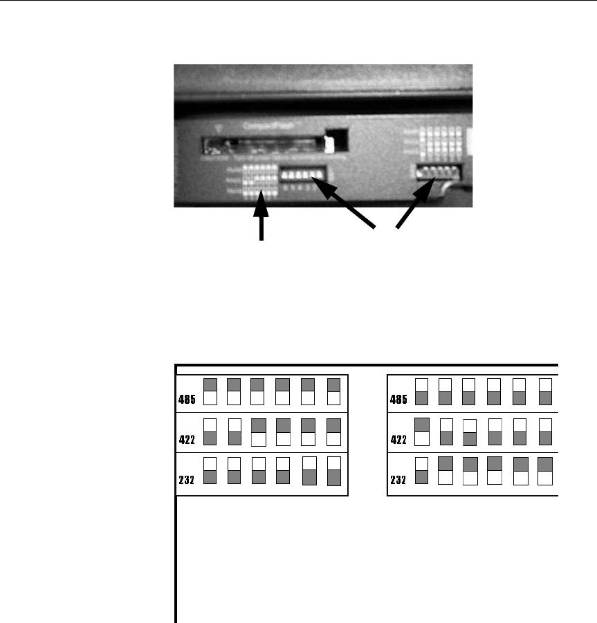
Figure 3-1COM2 Dip Switch Cutout and Settings
Figure 3-2 displays the settings for the COM2 port. A similar diagram
is located on the side of the PA PowerStation next to the DIP switch
cutout.
Figure 3-2Dip Switch Settings
To change the DIP switch settings, complete the following steps:
1. Choose the appropriate DIP switch settings from the diagram
displayed on the back of the PA PowerStation or from Figure 3-2.
2. Using a pointed instrument such as a pen or pencil, flip the
Dip SwitchesDip Switch Settings
Switch SW1 Switch SW3
• The gray boxes represent the tip of the switch.
• The upper half of the switch is the on position, and
the lower half of the switch is the off position.
Available Connectors Chapter 2: Introducing the PA PowerStation
18 PA PowerStation User Guide
switches to the appropriate settings through the viewing window.
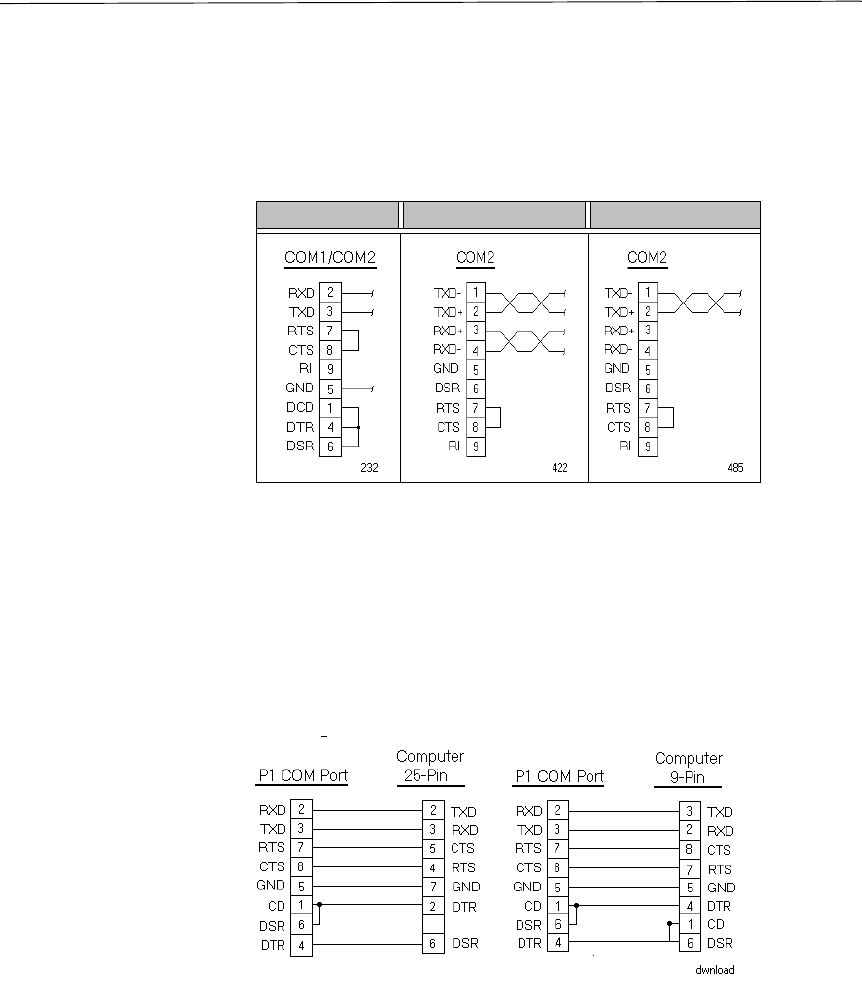
Figure 3-3 displays the pinouts and cable settings required for
communicating with COM1 or COM2 using the RS-232, RS-422 or
the RS-485 protocol.
Important Be careful not to connect any wires to unused connector pins.
Transferring Files from a PC to the PA PowerStation
You can transfer files from a PC to the PA PowerStation in one of three
ways—through the Ethernet, the Compact Flash, or a Serial Transfer.
If you plan to use a Serial Transfer, you will need a null modem cable.
To construct your own cables, refer to Figure 3-4 for the appropriate
settings. Then continue with step 1 below:
Figure 3-4Serial Transfer Cable Diagram
RS-232 RS-422 RS-485
Figure 3-3Pinouts and Cable Settings

Chapter 2: Introducing the PA PowerStation Available Connectors
PA PowerStation User Guide 19
1. Connect a null modem serial cable to an available serial port on
the IBM-PC.
2. Connect the other end of the cable to the serial port on the PA
PowerStation.
Connecting a Serial Mouse
If you need to connect a serial mouse to the serial port on the PA
PowerStation, you must check the settings to ensure that a COM port
is not already configured as a Download only port. If the COM port
that you want to use for the mouse is already assigned for Download,
complete the following steps:
1. Select Settings from the MachineShop Shell Main Menu.
2. Select Direct Serial from the Settings menu.
3. Select Port.
4. Select the COM port that you want to use as the Download port.
Or, you can select Disable to prevent any COM port from being
used as a COM port.
5. If the Serial Mouse is not already connected to the PA
PowerStation, connect it now.
6. Reboot the workstation.
Available Connectors Chapter 2: Introducing the PA PowerStation
20 PA PowerStation User Guide
Connecting to a Serial Printer
When connecting a serial printer to the PA PowerStation, you will
need to prepare the serial port for the printer. First you will need to
adjust the mode settings to the settings on the printer. See To Adjust the
Mode Settingsbelow.
If you plan to print to a serial port that was configured for
downloading, you will need to reconfigure the serial port. See To Print
to a Port Configured for Downloading on page 21.
To Adjust the Mode Settings
To connect a serial printer to the PA PowerStation, you must change
the mode settings for one of the serial ports to match those of your
printer. The easiest way to change these settings is to use
MODE.COM. MODE.COM can modify the following options:
baud: 110, 150, 300, 600, 1200, 2400, 4800, 9600
parity: N - none, O - odd, E - even
databits: either 7 or 8
stopbits: either 1 or 2
CTC includes MODE.COM on the PA PowerStation’s Compact Flash
card and the ROM-DOS installation CD shipped with your
PowerStation.
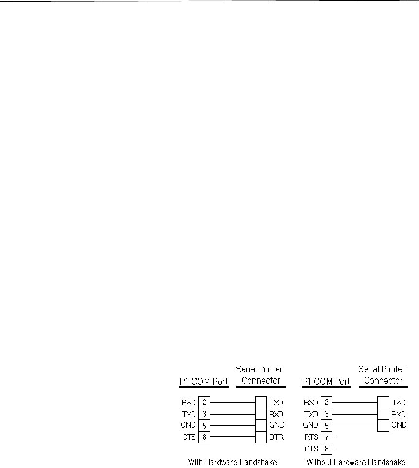
Figure 3-5 illustrates the appropriate settings for the PA PowerStation
COM Port and the Serial Printer Connector with hardware
handshaking and without hardware handshaking.
Figure 3-5Serial Printer Cable Diagram
Use Figure 3-5 as a reference when connecting a serial printer to the
PA PowerStation. Then complete the following steps:

Chapter 2: Introducing the PA PowerStation Available Connectors
PA PowerStation User Guide 21
1. From the Windows desktop, open the Startup directory within
Interact project:
C:\Machshop\Projects\Interact\*Project Name*\Startup\
Important Be sure to replace the pound sign with the appropriate port
number when completing the next step.
2. Within the Startup folder, create a new AUTOEXEC.BAT file
with the following line.
MODE COM#:baud,parity,databits,stopbits
Example If you are communicating at 9600, NONE, 8, and 1, use:
MODE COM1: 9600,N,8,1
3. Launch the MachineShop Toolbar.
Note When you download the project containing
AUTOEXEC.BAT and MODE.COM from your
development system to the PowerStation, MachineShop
transfers the AUTOEXEC.BAT file you created in step 2 and
MODE.COM into the \STARTUP directory specified by the
INTERACT_STARTUP environment variable. This
environment variable resides in the PowerStation’s
AUTOEXEC.BAT file.
4. Download the project.
Note When MachineShop finishes the download, a prompt will
display asking whether you want to restart the computer.
When you restart, MODE.COM will configure the COM port to
the required baud rate.
5. Restart the PowerStation.
To Print to a Port Configured for Downloading
If you plan to print to a port that is configured for downloading, you
will need to reconfigure the port before you can print to it. To
reconfigure the port, complete the following steps:
1. Disable downloading for that port.

Available Connectors Chapter 2: Introducing the PA PowerStation
22 PA PowerStation User Guide
2. Restart the PA PowerStation.
Note Restarting the PowerStation allows MODE.COM to reset the
communication settings for that port.
3. Select Settings from the Main Menu.
4. Choose TCP/IP from the selections displayed.
5. Select Net Setup from the menu.
Important The configuration may already be set to Download Only. If not,
continue with step 6. Otherwise, skip to step 8.
6. Depending on how your PA PowerStation is configured, select the
appropriate Net (Net 1, Net 2, or Net 3).
7. Choose Download Only from the options displayed.
8. Continue to Back out until you reach a prompt that indicates the
TCP/IP configuration has changed and asks whether you want to
Reboot.
9. Choose Yes to reboot the PA PowerStation. This will save your
changes.
Keyboard/Mouse
Port The PA PowerStation’s CPU board includes a keyboard port that
accepts any IBM AT-compatible keyboard, including 84-key standard
keyboards and 101-key enhanced keyboards.
Connecting a PS/2 Mouse
If you prefer to use a mouse instead of the touchscreen, CTC
recommends that you only use a Microsoft PS/2-style mouse,
specifically an 802.3 Microsoft-compatible mouse.
CTC has found that some Microsoft-compatible PS/2 mice do not
work correctly with the PA PowerStation. In addition, connecting any
mouse directly to the keyboard port will cause the mouse to
malfunction.
Ethernet Port The PA PowerStation has an Ethernet RJ45 port with an Intel
82551ER 10/100 Mbps base-T controller that allows you to connect
the PowerStation to a Local Area Network.
Chapter 2: Introducing the PA PowerStation Available Connectors
PA PowerStation User Guide 23
See Ethernet Pinouts.
CompactFlash The PA PowerStation comes with a Compact Flash (CF) card. The CF
is used as a removable hard drive that is recognized as drive C and
provides non-volatile memory storage. A CF is frequently used to
supplement or replace a hard drive because of its durability. The CF is
well-suited for rugged environments where the PowerStation may
vibrate or shake. Although the CF is removable, it is used as an IDE
drive, which means you cannot remove it while the PowerStation is
switched on.
CTC recommends that you purchase at least one additional CF card to
serve as a backup for your primary CF card. You may decide to own
several cards to store different projects. You can purchase additional
CF cards through CTC.
Caution Do not remove or insert the CF card when the unit is powered
on or data on the card could be corrupted.
Pin# Signal
1TX+
2TX-
3RX+
4N/C
5N/C
6RX-
7N/C
8N/C
Table 2-12: Ethernet Pinouts

Drive Definition and Memory Chapter 2: Introducing the PA PowerStation
24 PA PowerStation User Guide
Drive Definition
and Memory
The PA PowerStation has one drive, C, which is a Compact Flash Card
(Read/Write) of size 32MB. This drive is the system start drive and
Project disk. It stores the project, system files, MachineShop, and
applications. Download files to this drive.
Memory Guidelines If you are using MachineShop to develop your HMI applications, refer
to these memory guidelines when you develop projects. There are two
memory storage types, System SDRAM and Compact Flash. The
capacity and use of the System SDRAM is 32MB.
The capacity and use of the Compact Flash is 32MB flash memory. Of
this 8MB can store APM, PTM, and AMM, as well as four additional
runtime models, two drivers, and approximately 30 screens. Extra
modules require more storage (four modules/MB).

Chapter 2: Introducing the PA PowerStation Replacement Components
PA PowerStation User Guide 25
Replacement
Components
The PA PowerStation is designed to be a simple yet reliable unit to
maintain. However, if you need to purchase replacement components
for the PowerStation, CTC carries a complete line of replacement
components.
CompactFlash Card If you need additional storage capacity for the PA PowerStation, you
can purchase additional Compact Flash cards from CTC. CTC
recommends that you purchase at least one additional flash card to
serve as a backup for your primary CF. See Using the Compact Flash
Card on page 47 for instructions on how to replace and reformat CF
cards.
SDRAM If you need to upgrade or replace the PA PowerStation’s SDRAM,
CTC carries replacement SDRAM (SODIMM). The PA PowerStation
comes with a 32MB 144-pin SODIMM for SDRAM, but you can
replace that module with a 64MB or 128MB 144-pin SDRAM for
greater capacity. To replace the SDRAM, see Replacing the SDRAM
on page 61.
Note 16M of the SDRAM is used for video memory. The amount of
memory reported is the size of the SDRAM minus 16M. For
example, if you have 32M of SDRAM, only 16M is reported.
Both PC100 and PC133 speeds are supported. A jumper must be set to
match the speed of the version that you purchased.
Touchscreen Occasionally, you may find that you need to replace the PA
PowerStation’s touchscreen, depending upon the environment in
which you are operating the PowerStation. Replacement kits for the
10" model are available through CTC. The 10" model is the only
model that has a field-replaceable Touchscreen kit. See Customer
Support Services on page 5 to order the kit.
Backlight Bulb You may replace the backlight bulb on the 7.7" and 10" PA
PowerStation monitors. You cannot replace the backlight bulb on the
5", 6", and 8" monitors.
You can also send the PowerStation to CTC’s repair center. See
Customer Support Services on page 5.
Replaceable Fuse The PA PowerStation has a protective fuse that can be replaced by
qualified personnel. See Replacing the Fuse on page 41 for complete
instructions.

Optional Components Chapter 2: Introducing the PA PowerStation
26 PA PowerStation User Guide
Optional
Components
CTC has an optional component that you may want to purchase for the
PA PowerStation—an AC Power Supply.
AC Power Supply The PA PowerStation uses DC power to save space and limit the
amount of heat generated by the unit. However, if you require the
PowerStation to use AC power, you can purchase an AC Power Supply
kit that includes an AC Power Supply and a power cord.
You can also purchase mounting brackets for the Power Supply. See
Preparing a Location for the AC Power Supply on page 32 for
instructions on how to mount the AC Power Supply.
Caution Do not apply AC power to the unit or damage could occur.

Chapter 3
Installing the PA
PowerStation
You are now ready to install the PA PowerStation in a permanent
location. This chapter will help you select an appropriate location
for the unit. It also provides instructions for creating a cutout for
the unit, and describes how to install and start up the unit.
Chapter Contents
Selecting a Location 28
Preparing for Installation 31
Installing the PA PowerStation 33
Starting Up the PA PowerStation 37

Selecting a Location Chapter 3: Installing the PA PowerStation
28 PA PowerStation User Guide
Selecting a
Location
The first step when installing the PA PowerStation is to select an
appropriate location for the unit. This is the most important aspect of
the installation process because the location you select can affect the
PowerStation’s performance, ease-of-use, and life-expectancy. This
section provides some guidelines that you should follow when
selecting a location for the PowerStation.
Class I, Division 2
Guidelines If you purchased a Class I, Division 2-compliant PA PowerStation,
you must always follow these guidelines to maintain a safe operating
environment:
1. Suitable for use in Class I, Division 2, Groups A, B, C, and D
hazardous locations only.
2. Warning: Explosion Hazard—DO NOT connect or disconnect
cables while power is applied unless area is known to be
nonhazardous. Keyboard and Mouse Ports are for system set-up
and diagnostics and are NOT intended for permanent connection.
3. Warning: Explosion Hazard—CLASS 1 DIV 2 approval
requires Power Switch restraints in hazardous environments.
Nonincendive for CLASS 1, GROUPS A, B, C, and D hazardous
locations. Temperature code: T5.
4. Make sure that the PA PowerStation’s on/off switch is secured in
the on position using the supplied bracket.
5. When performing field wiring, always use copper wire with 60C
or 60/75C insulation and a tightening torque of 7.0 lb./in. (0.79 N-
m).
Environmental
Guidelines The environment is the area where the PA PowerStation will be
located. In general, you should select a place that limits the unit’s
exposure to adverse conditions such as dust, oil, moisture, and
corrosive vapors.
Touchscreen Considerations
The PA PowerStation’s touchscreen is designed to meet the NEMA 4
rating. You should mount the PowerStation in an enclosure that
supports this rating in order to provide further protection.
The PA PowerStation’s touchscreen is resistant to a variety of
chemicals. See Faceplate Chemical Resistance on page 13 for a list of
these chemicals. Make sure that the touchscreen is not exposed to

Chapter 3: Installing the PA PowerStation Selecting a Location
PA PowerStation User Guide 29
chemicals other than those listed in Faceplate Chemical Resistance on
page 13.
Electrical Guidelines To minimize unwanted electrical interference, select a location away
from machinery that produces intense electrical noise. If you cannot
do this, isolate input power to the unit and separate all data
communication cables used with the unit from AC power lines.
See Electrical Specifications on page 11 for a list of the PA
PowerStation’s electrical specifications. Make sure that your power
source is compatible with the PowerStation before starting the unit.
Field Terminal Wiring Requirements
In order to comply with UL 508 and 1604 requirements, use copper
wire with 60C or 60/75C insulation and a tightening torque of 7.0 lb/
in. (0.79 N-m) when connecting field terminal wiring to the
PowerStation.
Temperature
Guidelines You can safely operate the PA PowerStation within the temperature
range specified in Environmental Specifications on page 10. However,
if you are using a protective enclosure, remember that the temperature
within an enclosure is generally higher than the external temperature.
If the PowerStation is operating inside an enclosure at temperature
levels above its rated ambient temperature, you must cool the
enclosure.
Enclosure
Guidelines Select an enclosure that is large enough to allow free airflow in and
around the unit. You should allow a minimum of 2 inches between the
enclosure and the top, bottom, and sides of the PA PowerStation.
Also, make sure that the surface of the enclosure on which the PA
PowerStation is mounted is flat and free of raised or depressed areas.
AC Power
Guidelines You will need to read the AC Power Guidelines only if you intend to
operate the PA PowerStation using AC power. If you intend to operate
the PowerStation using DC power, skip to Preparing for Installation
on page 31.
The PA PowerStation ordinarily uses DC power. However, you can
operate the PowerStation with AC power by using an optional AC
Power Supply available from CTC. If you purchased the optional AC
Power Supply, you must select a location that provides protection
from dust, oil, moisture, and corrosive vapors. If your enclosure is

Selecting a Location Chapter 3: Installing the PA PowerStation
30 PA PowerStation User Guide
large enough, you can mount the Power Supply in the enclosure with
the unit.
Caution Do not apply AC power to the unit or damage may occur.

Chapter 3: Installing the PA PowerStation Preparing for Installation
PA PowerStation User Guide 31
Preparing for
Installation
Once you select a location for the PA PowerStation, you will need to
create a cutout for the unit.
If you plan to operate the PA PowerStation using AC power, and you
purchased CTC’s optional AC Power Supply, you will need to prepare
a location for the Power Supply also.
Procedures for creating the cutout and preparing a location for the AC
Power Supply are described below. If you already have an appropriate
cutout and are using DC power, continue with Installing the PA
PowerStation on page 33.
Creating the Cutout The PA PowerStation comes with a template that is designed to
simplify the task of creating a cutout for the unit. Be sure to follow the
cutout dimensions on the template precisely so that the PowerStation
will properly seal in its enclosure.
Create a Cutout
To create the cutout, complete the following steps:
1. Attach the template securely to the mounting surface.
2. Cut out the shaded area on the template referred to as the "Panel
Cutout Area." To maintain the flatness of the mounting surface,
CTC recommends that if you punch out the mounting hole, you
should maintain proper surface flatness and edge quality.
The cutout dimensions for the PA PowerStation are shown in the
following table:
3. Debur the edges of the cutout area, removing dirt and debris that
might come in contact with the unit.
4. More information is available on the CD that comes with the PA
PowerStation. Be sure to refer to the dimensional drawings found
on the CD when creating your cutout.
PA Model Cutout Height Cutout Width
PA05S
PA06S
4.91" 6.20"
PA08S
PA08T
6.08" 8.67"
PA10T 9.86" 12.60"

Preparing for Installation Chapter 3: Installing the PA PowerStation
32 PA PowerStation User Guide
Preparing a Location
for the AC Power
Supply
You will need to read Preparing a Location for the AC Power Supply
only if you intend to operate the PA PowerStation using AC power. If
you plan to use DC power, proceed to Installing the PA PowerStation
on page 33.
If you plan to operate the PA PowerStation with AC power, and you
purchased CTC’s optional AC Power Supply and the mounting kit, use
the template that came with the mounting kit to prepare a location for
the power supply. You can prepare a location for the power supply
inside or outside the enclosure where the PowerStation is installed.
Note If you decide to mount the Power Supply in an enclosure, mount
it on the bottom or the side of the enclosure to provide the best
convection cooling.
Prepare the Power Supply Mounting Surface
To prepare the mounting surface, complete the following steps:
1. Securely attach the template to the mounting surface.
2. Drill and debur four 0.17” (4.3mm) holes.
Chapter 3: Installing the PA PowerStation Installing the PA PowerStation
PA PowerStation User Guide 33
Installing the PA
PowerStation
Once you prepared the location for the PA PowerStation, you can
install the unit. Installation will involve mounting the PowerStation
and if you are using CTC’s optional AC Power Supply, mounting the
power supply. Both procedures are described below.
Mounting the PA
PowerStation The PA PowerStation is designed to be mounted using 4 - 6 screws.
These screws are secured to the unit with metal clips. For your
convenience, CTC includes all necessary mounting hardware with the
unit.
Mount the PowerStation
Note Necessary mounting clamps and screws are shipped with your
system.
To mount the unit, complete the following steps:
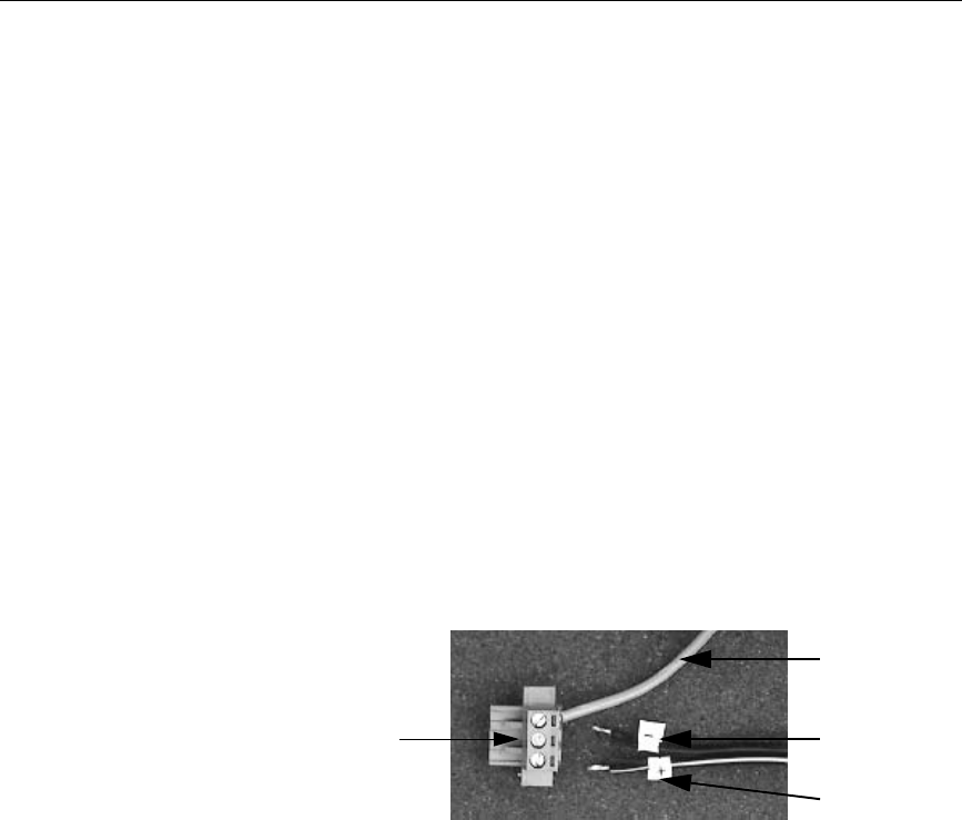
1. Prepare the power source for the unit by sliding the positive and
negative wires into the appropriate slots on the power connector.
See Figure 3-6.
Figure 3-6 Power Connector and Positive/Negative wires
2. Connect the ground cable from the power connector to an earth
ground.
3. Gently insert the PA PowerStation into the cutout from the front.
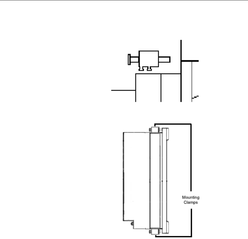
4. Attach the 4-6 mounting clamps, with their screws, to the back of
the unit in the spaces provided.
Note The number of clamps depends on the model. The shape of the
prongs at the bottom of each clamp also depends on the model.
The 5", 6", and 8" models use a T-shape clamp, and the 10"
models use an L-shape clamp.
Ground wire
Negative wire
Positive wire
Power
connector
Installing the PA PowerStation Chapter 3: Installing the PA PowerStation
34 PA PowerStation User Guide
Clamp shape and location on the 5" and 6" units:
Chapter 3: Installing the PA PowerStation Installing the PA PowerStation
PA PowerStation User Guide 35
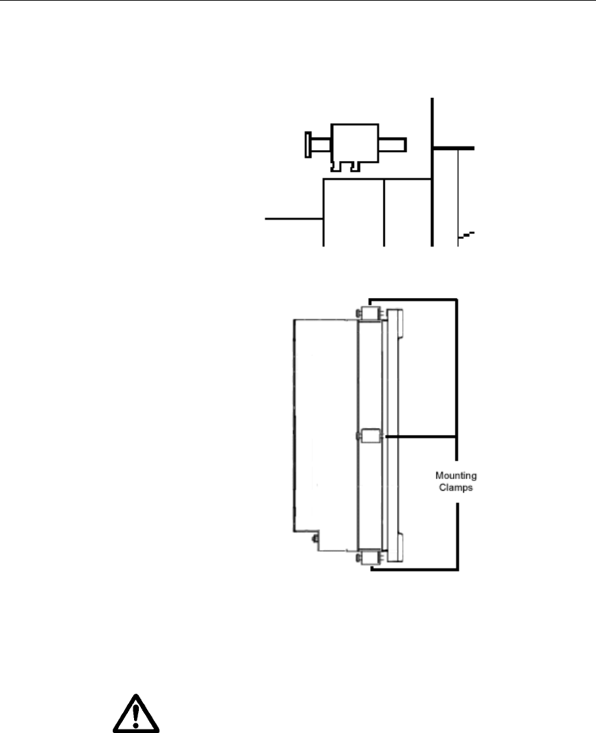
Clamp shape and location on the 10" units:
5. Insert the slamps into the larger portion of the slots, and then slide
them toward the outside of the unit.
6. Tighten each of the mounting screws against the front of the
enclosure using a torque of 6 lb/in for 5" and 6" units. Use 7 lb/in
for the 8" units.
Important Tighten the nuts in a crosswise sequence to ensure a good seal
and to prevent damage to the unit.

Installing the PA PowerStation Chapter 3: Installing the PA PowerStation
36 PA PowerStation User Guide
7. Attach the power connector that you prepared in steps 1 and 2 to
the back of the unit.
Caution Over-tightening the screw/clamp assemblies may damage the
PA PowerStation. Under-tightening may not guarantee a
NEMA 4 seal.
Note Tightening the screw/clamp assemblies may not insure that the
gasket seal is totally depressed by the bezel. It may be possible
to see a small edge of the gasket between the bezel and the
enclosure.

Chapter 3: Installing the PA PowerStation Starting Up the PA PowerStation
PA PowerStation User Guide 37
Starting Up
the PA
PowerStation
Once the PA PowerStation has been mounted, you are ready to start up
the unit. This procedure is described below.
Before connecting a power cord to your unit, make sure that you have
read and understood Environmental Specifications on page 10 and the
Testing Specifications on page 12 of this manual. Also, be sure to
follow the guidelines listed below:
•For permanently connected equipment, incorporate a readily
accessible disconnect device in the fixed wiring.
Important Proper installation of this PowerStation model for use in
European Union countries requires the use of a harmonized
power cord (the power cord must be identified with the <HAR>
symbol). Make sure that the PowerStation is connected to the
main supply only with a harmonized power cord.
1. Ensure the power on/off switch is in the off position.
2. Connect the power cord to your voltage source. Voltage input to
the unit should be within the range specified in the Environmental
Specifications on page 10.
Note Be sure to make DC connections.
3. Connect the power cord plug to the PA PowerStation.
4. Turn the PA PowerStation on.
The PowerStation will automatically load the MachineShop Shell
or an Interact application, if the Shell is configured to start
Interact automatically.
You are now ready to download a project to the PA PowerStation. If
you’re using MachineShop software, refer to the MachineShop
Getting Started Guide for information about downloading projects.

Starting Up the PA PowerStation Chapter 3: Installing the PA PowerStation
38 PA PowerStation User Guide

Chapter 4
Maintaining and
Troubleshooting the PA
PowerStation
The PA PowerStation is designed to provide years of trouble-free
operation even in the harshest environments. However, you may
occasionally need to perform routine maintenance on some of the
PowerStation’s components.
This chapter provides instructions on PA PowerStation
maintenance, as well as steps for troubleshooting problems that
may occur in operation.
Chapter Contents
Installing and Replacing Parts 40
BIOS Setup 42
Maintaining the Touchscreen 43
Using the Compact Flash Card 47
Modifying the AUTOEXEC.BAT File 51
Configuring the Ethernet Interface 53
Resolving Problems 55
Replacing the SDRAM 61

Installing and Replacing Parts Chapter 4: Troubleshooting the PA PowerStation
40 PA PowerStation User Guide
Installing and
Replacing Parts
This section includes instructions for performing internal maintenance
on the PA PowerStation. To prevent injury to yourself or damage to the
PowerStation, you will need to carefully read and understand the
procedures described in this section. This section will show you how
to perform the following operation:
•Replacing the Fuse on page 41
Before you begin, this section describes electrostatic discharge (ESD)
precautions that you should take whenever you work inside the PA
PowerStation.
Warning For safety reasons, only qualified service personnel should open
the PowerStation.
Electrostatic
Discharge
Precautions
Modern integrated electronic devices, especially CPUs and memory
chips, are extremely sensitive to electrostatic discharges (ESD) and
fields. Before you disassemble the PA PowerStation, follow these
simple precautions to protect you and the PowerStation from harmful
ESD.
• To avoid electric shock, always disconnect power from the
PowerStation before opening or disassembling the unit. Do not
touch any components on the CPU card or other cards while the
PowerStation is on.
• Disconnect power before making any hardware configuration
changes. A sudden static discharge as you connect a jumper or
touch any internal parts may damage sensitive electronic
components.
• Only handle internal components in an ESD-safe location, using
appropriate grounding methods.
• Wear a grounding wrist strap for continuous protection.
• Always ground yourself to remove any static charge before you
touch the CPU card.
• Be particularly careful not to touch the chip connectors.
• Keep any card or SDRAM module in its anti-static packaging
when it is not installed in the PowerStation. Place it on a static
dissipative mat when you are working on it.
Once you have read and understand the ESD safety precautions, you
are ready to continue with the appropriate instructions.
Chapter 4: Troubleshooting the PA PowerStation Installing and Replacing Parts
PA PowerStation User Guide 41
Replacing the Fuse The PA PowerStation has a protective fuse that you can replace by
opening up the back cover. An ohm meter is required to see whether
the fuse is open or closed.
To replace the fuse, complete the following steps:
1. Turn off the PA PowerStation.
2. Disconnect the PowerStation from its power source.
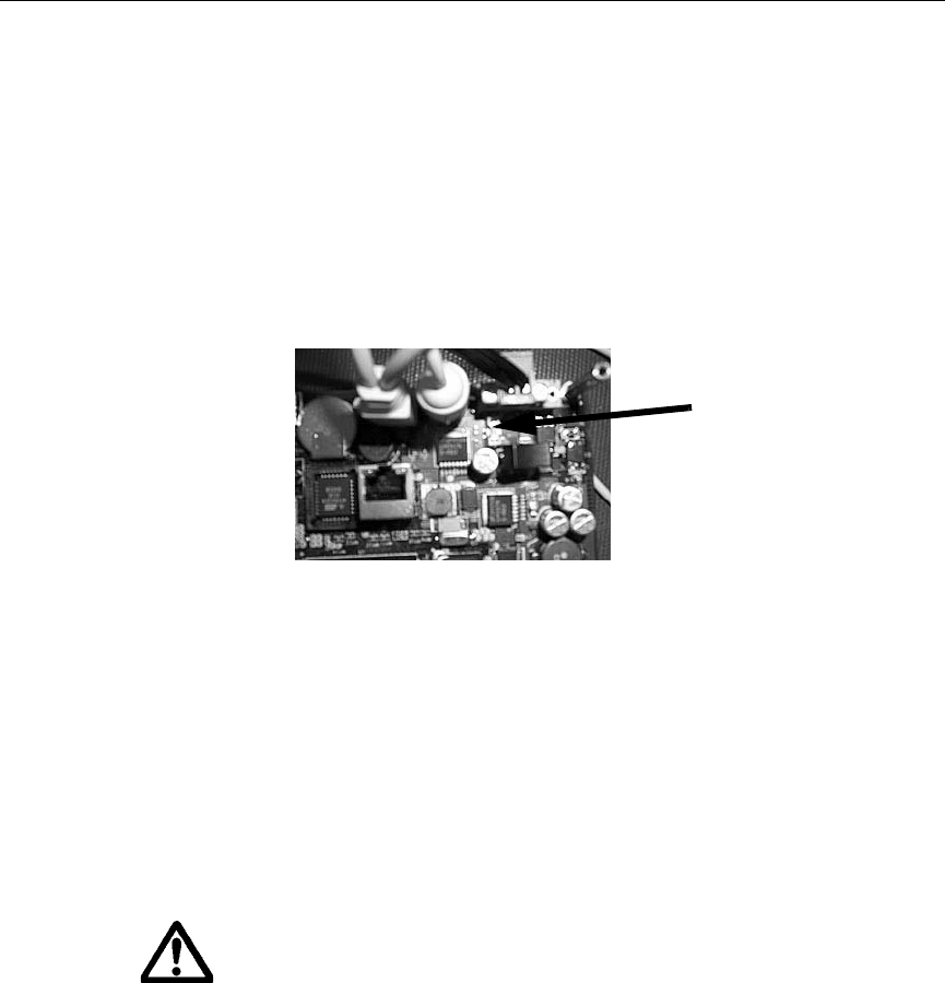
3. Remove the back cover of the unit.
4. Locate the fuse on the board according to the picture below.
Figure 4-1 Replaceable Fuse
5. Use an ohm meter to see if the fuse is open or closed.
a. If open, use a pair of needlenose pliers to lift the fuse from the
fuse holder.
b. If closed, the fuse is okay and there is no need to replace it.
6. To replace the fuse, use a Littelfuse Nano SMF Very Fast-Acting
Type fuse. The part number is R451 002.
Note This is a 2 amp fuse.
Caution Using a fuse that is rated differently than indicated here can
cause damage or fire to occur.
7. Insert the new fuse into the fuse holder and reassemble the unit.
Fuse

BIOS Setup Chapter 4: Troubleshooting the PA PowerStation
42 PA PowerStation User Guide
BIOS Setup The PA PowerStation is limited in BIOS configuration changes that the
user can perform. The BIOS setup window lets you remove the CTC
splash screen only. If you want to reset this BIOS setting, press the
Delete key while the system is starting up to display the BIOS setup
window.
Note Accessing the BIOS settings requires a keyboard.
To access the BIOS settings, complete the following steps:
1. Shut down the system.
2. Connect a keyboard to the system.
3. Restart the system.
4. While the system is starting, press the Delete key on the keyboard.
5. The BIOS Setup Utility screen appears.
Removing the CTC
Splash Screen To remove the CTC splash screen, complete the following steps:
1. Press the Page Up key to toggle the Boot-time Diagnostic Screen
setting to [Disabled].
2. Press the Right arrow key to highlight Exit and then press Enter.
3. Press Enter again to save your changes and exit.

Chapter 4: Troubleshooting the PA PowerStation Maintaining the Touchscreen
PA PowerStation User Guide 43
Maintaining the
Touchscreen
The touchscreen for the PA PowerStation is durable and able to
operate smoothly in harsh environments where strong chemicals exist.
However, from time to time you may need to perform general
maintenance on the touchscreen. This section provides step by step
instructions on how to complete the the following tasks:
Cleaning the
Touchscreen Occasionally, you may wish to clean the PA PowerStation’s
touchscreen. Clean the touchscreen using warm, soapy water and a
cloth. You may also use a non-abrasive cleaner. See Faceplate
Chemical Resistance on page 13 for a list of substances the screen can
resist with no visible effect.
Do not use any harsh material or powder, such as steel wool or
abrasive cleansers, to clean the touchscreen surface. The surface is
sensitive to scraping, sharp blows, and punctures. Therefore, keep
screwdrivers or other sharp objects away from the touchscreen
surface.
Warning Do not clean the touchscreen while Interact is in Run mode.
Clean the unit when it is switched off to avoid inadvertently
activating an Interact device (button, slide, etc.).
Calibrating the
Touchscreen The PA PowerStation’s touchscreen is calibrated before leaving CTC.
However, you may need to calibrate the touchscreen for one of several
reasons:
• when you use the PA PowerStation for the first time
• when you replace the touchscreen
• when the position of the cursor does not match the location where
the user touches the screen
Maintaining the Touchscreen Chapter 4: Troubleshooting the PA PowerStation
44 PA PowerStation User Guide
Using the MachineShop Shell Calibration Utility
The MachineShop Shell comes with a calibration utility that allows
you to calibrate the touchscreen in DOS mode.
Enter the Calibration Mode
In the following steps, you will enter the calibration utility in
MachineShop Shell. To enter the calibration utility, complete the
following steps:
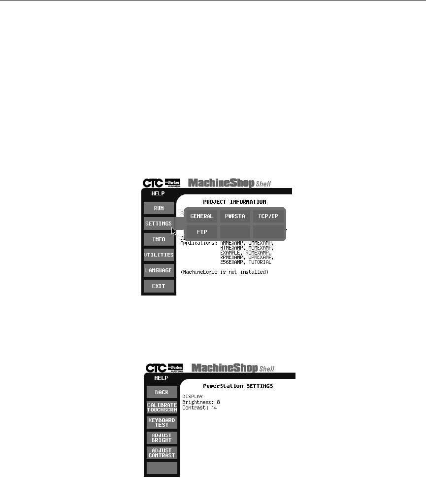
1. On the MachineShop Shell Main Menu, press the Settings button.
See Figure 4-2.
Figure 4-2 Settings Submenu
2. On the Settings submenu, press the PWRSTA button. The
PowerStation Settings menu will appear as shown in Figure 4-3.
Figure 4-3 PowerStation Settings Menu
3. Press Calibrate Touchscreen.
Chapter 4: Troubleshooting the PA PowerStation Maintaining the Touchscreen
PA PowerStation User Guide 45
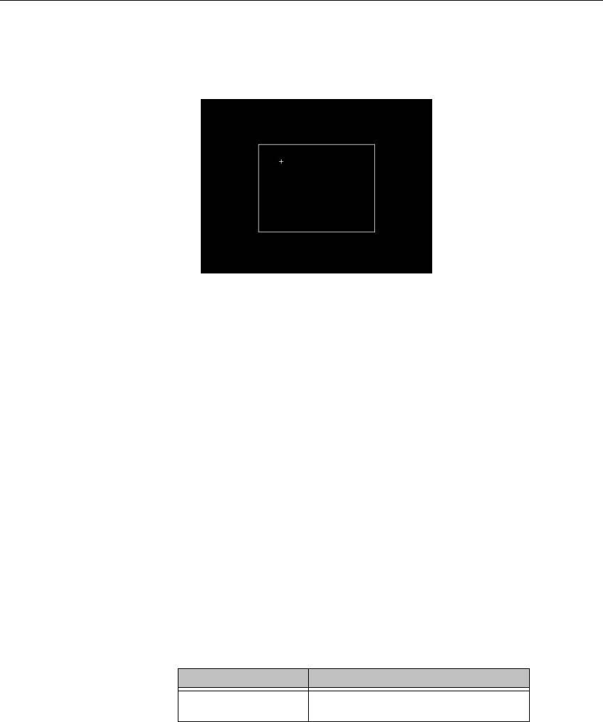
The calibration routine will run automatically.
4. Use your finger to touch the + on the screen.
5. Repeat the previous step two more times. Each time you touch the
+ you will hear a faint beep to indicate that the touch has been
accepted.
After the third time, your touchscreen will be calibrated.
Important If you calibrated the touchscreen and the cursor moves
vertically when your finger moves horizontally on the screen or
vice versa, the touchscreen cable may not be connected to the
motherboard properly. Call a CTC customer support
representative. See Customer Support Services on page 5.
Adjusting the
Contrast You may adjust the contrast on the PA PowerStation. The contrast is
a property of the LCD.
Note The Brightness property is fixed and cannot be adjusted.
This property can be adjusted on the STN display only. So before you
begin, you will need to determine whether you own an STN or a TFT
display. To distinguish between the two types of displays, locate the
model number on the back of the PA PowerStation unit and compare
the third digit in the model number with the third digit in Table 4-1:
Display Type to determine the type of display you own.
Model No. View Size
PA-05S/06S/08S-
1XX STN Display - Quarter VGA
Table 4-1: Display Type
Maintaining the Touchscreen Chapter 4: Troubleshooting the PA PowerStation
46 PA PowerStation User Guide
• If your PA Series has an STN display, continue with Adjusting the
Contrast (For STN Units Only).
• If you have a TFT display, you cannot adjust the contrast.
Adjusting the Contrast (For STN Units Only)
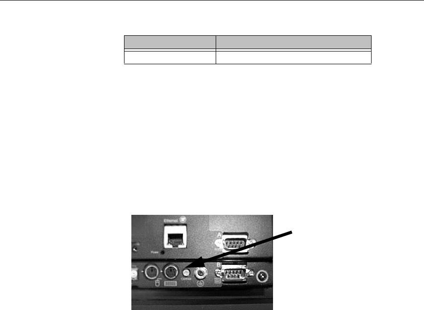
To adjust the contrast on an STN display, complete the following steps:
1. Find the contrast adjustment on the back of the PowerStation. See
Figure 4-4.
Figure 4-4 Contrast Adjustment
2. Using a Phillips screwdriver, turn the screw to adjust the contrast
to the desired level. This is a very small adjustment.
PA-08T/10T-1XX TFT Display - Full VGA
Model No. View Size
Table 4-1: Display Type
Contrast
Adjustment
Chapter 4: Troubleshooting the PA PowerStation Using the Compact Flash Card
PA PowerStation User Guide 47
Using the
Compact Flash
Card
The PA PowerStation uses a removable Compact Flash (CF) card for
storage purposes. You can remove the CF card, update the application
files on the CF card from a PC, and then reinstall the CF card in the
PowerStation.
CTC recommends that you purchase at least one additional CF card to
serve as a backup for your primary CF card. You may wish to have
several cards to store different projects. You can purchase additional
CF cards from CTC.
Replacing the
Compact Flash At some point, you will probably need to remove the CF card from the
PA PowerStation flash socket for one reason or another. To do so,
complete the following steps:
1. Turn off the PA PowerStation.
Caution The PowerStation must be turned off when inserting or
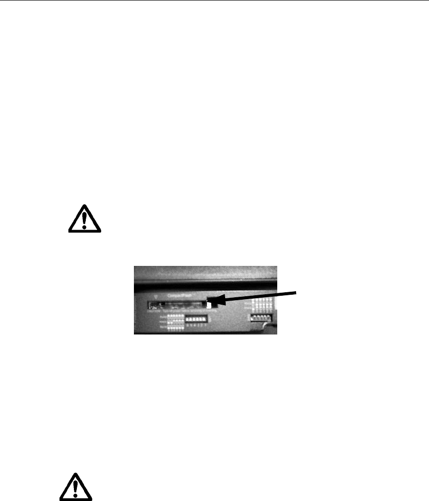
removing the CF card to avoid corrupting data.
2. Locate the ejector next to the CF socket.
Figure 4-5 Compact Flash Ejector
3. Push the ejector button to pop the CF card out.
4. Remove the CF card.
5. Carefully insert the new card with the connector on the card
aligning with the pins inside the socket.
6. Push the CF into the slot until the card is securely seated in the
socket. Do not force!
Important The CompactFlash has an arrow near one edge that always lines
up with a matching arrow on the label of the PA PowerStation.
Insert the CompactFlash so the arrows line up and the card seats
properly. Do not force the CompactFlash in the wrong way.
Compact Flash
Ejector

Using the Compact Flash Card Chapter 4: Troubleshooting the PA PowerStation
48 PA PowerStation User Guide
Reinstalling the
PowerStation
Utilities
The PA PowerStation is shipped with the operating system and
software, which is installed on the CompactFlash card that comes with
your system.
Backup copies of your software are provided on the PA PowerStation
CD that ships with your system. If any of the software on your system
becomes lost or corrupted, you can reinstall it from this distribution
disk.
Restoring a CompactFlash Card
Because you use a CompactFlash (CF) card as the startup drive in a PA
PowerStation, you should create a bootable CF card for the system
from a blank or used card. This procedure will fix a ROM-DOS Shell
CompactFlash card and let you do the following:
• Reinstall the PowerStation Utilities onto a CF card
• Prepare a new CF card for use
You can easily reformat a CompactFlash card by using CTC’s
Flashback Utility, which restores the ROM-DOS operating system and
PA PowerStation operating files to a CF card in one operation.
When you use Flashback, the following software will be replaced on
your CompactFlash card:
• Operating system
•System drivers
• MachineShop Shell
Writing to the CompactFlash Card
To write to the CompactFlash card, you will need one of the following:
• A personal computer running Windows with a CD-ROM drive
and a SanDisk ImageMate or any CompactFlash card PC reader/
writer. A SanDisk ImageMate is a CompactFlash reader/writer
that connects to the personal computer through a USB port. You
can order a SanDisk ImageMate (model number IMG-2000) from
your local Parker distributor.
• A laptop computer running Windows with a CD-ROM drive and a
PCMCIA-to-CompactFlash adapter. The PCMCIA-to-
CompactFlash adapter lets you read from or write to a
CompactFlash card through your laptop’s PCMCIA slot. You can

Chapter 4: Troubleshooting the PA PowerStation Using the Compact Flash Card
PA PowerStation User Guide 49
order a PCMCIA-to-CompactFlash adapter (model number FLH-
ADPT-2000) from your local Parker distributor.
Reformatting the CompactFlash Card
Warning Manually formatting a CompactFlash card in Windows NT and
2000 before using Flashback could possibly make the CF card
unusable.
Warning Removing the CompactFlash card: During a disk transfer
procedure, do not remove the CF card before issuing a Stop or
shutting down the USB port service. Otherwise the last part of
the data will not transfer to the CF card.
To reformat a CF card for a PA PowerStation, complete the following
steps on a personal computer or laptop:
1. Insert the CompactFlash card into the CompactFlash card PC
reader/writer or the PCMCIA slot.
2. Insert the PA PowerStation CD into the CD-ROM drive.
3. Use Windows Explorer to locate the file FlashUtil.exe from the
Utilities directory on the CD-ROM drive.
4. Double-click FlashUtil.exe.
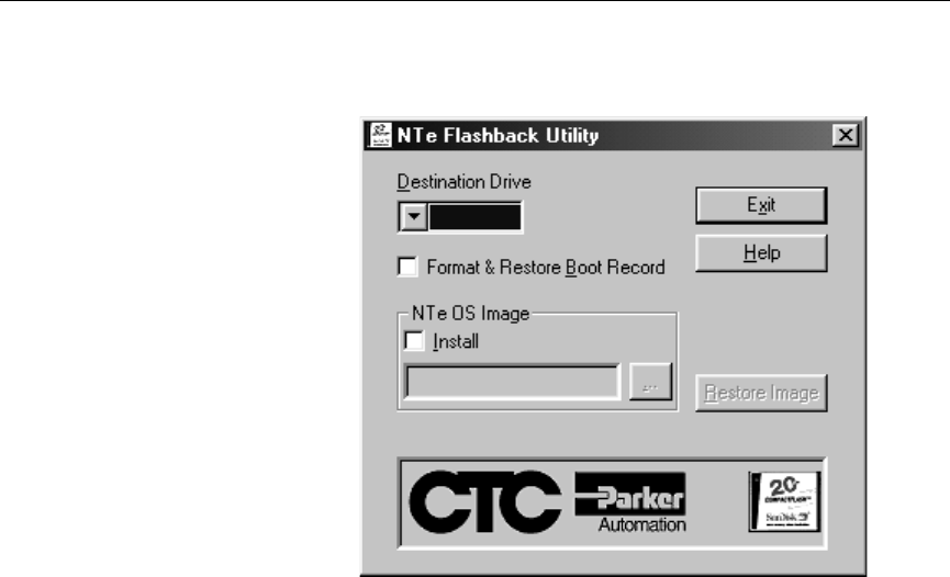
The Flashback Utility dialog box appears. (The NTe version is
shown below.)
Using the Compact Flash Card Chapter 4: Troubleshooting the PA PowerStation
50 PA PowerStation User Guide
Note Make sure that you are using at least revision 104 of the
Flashback Utility, which allows the formatting of the CF card
even if the boot sector of the CF card is unreadable to ROM-
DOS.
Reformatting a CompactFlash card using Flashback will erase
your projects from the CF card. You will need to download your
projects to the CF card again. After using Flashback, you may also
need to recalibrate your PA PowerStation display. For instructions,
see Calibrating the Touchscreen on page 43.
5. Click the down arrow for the destination drive and choose the
correct drive letter that was assigned to the CF.
6. Press the Restore Image button.
Note The Flashback Utility will first format the compact flash, and
then copy ROM-DOS, the Shell, and the utilities to the compact
flash.

Chapter 4: Troubleshooting the PA PowerStation Modifying the AUTOEXEC.BAT File
PA PowerStation User Guide 51
Modifying the
AUTOEXEC.BAT
File
The lines shown in the following table must appear in the PA
PowerStation’s AUTOEXEC.BAT file for the unit to operate
properly. The AUTOEXEC.BAT file that CTC supplies includes these
lines and is located in the \CTC directory on the PowerStation’s
Compact Flash card in a file called AUTOEXEC.CTC.
Please make sure that the AUTOEXEC.BAT file on your PA
PowerStation’s CF card includes the command lines shown in the left-
hand column of AUTOEXEC.BAT File.
Command Line Parameters Description
PATH C: \; C: \DOS; C: \CTC Sets up the default
DOS path.
LH C:\CTC\BIOSTSR Loads special
functions.
C:\CTC\PACTRL -A -S
IF ERRORLEVEL 108 GO TO
ERROR
Verifies this
CompactFlash is
running on a
PowerStation.
CD \CTC
IF EXIST C: \CTC\MOUSE.INI DEL
C: \CTC\MOUSE.INI
Required for the
MachineShop Shell to
detect a mouse in
some situations.
LH C: \CTC\MOUSE
:ITSA
If a mouse is
connected, installs the
mouse and creates a
new MOUSE.INI file.
SET TOUCH_PATH=C:
\HAMMOUSE
CALL %TOUCH_PATH% \TS.BAT
Initializes the
touchscreen drivers.
*SET INTERACT=C: \INTERACT Sets the Interact path.
*SET INTERACT_FILES=C:
\INTERACT\APPFILES Sets the application
path for Interact.
*SET INTERACT_STARTUP=
C: \STARTUP Sets up Interact
startup variables.
CD \NET
LH C: \NET\TCPIP Loads network drivers
--Novell and/or TCPIP
stack.
IF NOT EXIST C:
\STARTUP\NUL.EXT MD C:
\STARTUP
CD \STARTUP
IF EXIST C: \STARTUP\
AUTOEXEC.BAT CALL C:
\STARTUP\AUTOEXEC.BAT
Calls the second
AUTOEXECBAT file if
the line is contained
within a project file.
Table 4-2: AUTOEXEC.BAT File

Modifying the AUTOEXEC.BAT File Chapter 4: Troubleshooting the PA PowerStation
52 PA PowerStation User Guide
* Denotes a command line that is unnecessary on units without Interact.
For a complete listing of the AUTOEXEC.BAT file, see Appendix A.
CD \CTC
PSU Starts the
MachineShop Shell.
Command Line Parameters Description
Table 4-2: AUTOEXEC.BAT File
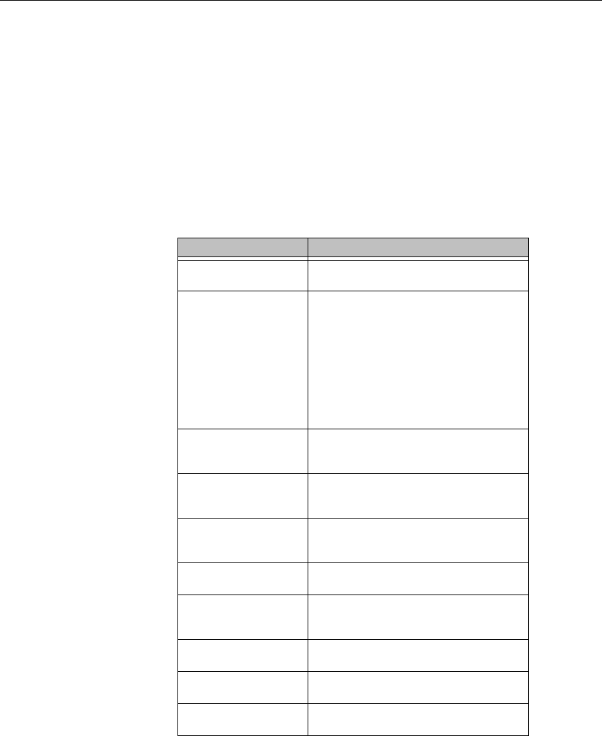
Chapter 4: Troubleshooting the PA PowerStation Configuring the Ethernet Interface
PA PowerStation User Guide 53
Configuring the
Ethernet
Interface
The \NET directory of the PA PowerStation’s CompactFlash contains
a configuration utility and all drivers necessary to configure the
Ethernet interface on the PowerStation. Backup copies of these files
are included on the MachineShop Shell Installation Disk. A list of the
files appears in \NET Directory Files.
Note The MachineShop Shell Installation Disk is part of the Runtime
Workstation Disk Set, which you can create from the
MachineShop Installation CD shipped with your PowerStation.
See the MachineShop Installation Booklet for instructions on
how to create this disk.
File Name Description
NET.BAT A sample batch file you can use to run
NetBIOS.
NET.CFG Stores the interrupts and memory for
the network drivers. The default
PowerStation configuration reserves
the following interrupts and I/O
addresses. You cannot use these for
the Ethernet interface.
• COM1: Int 4, I/O 3F8
• COM2: Int 3, I/O 2F8
• Touchscreen: Int 11, I/O 3E8
NETX.EXE The Novell Netware shell program
that makes the final connection with
the server.
*LSL.COM A Novell driver that enables the
workstation to communicate with
different protocols.
*IPXODI.COM A Novell driver that supports the IPX
protocol and other protocols over the
same network.
Plug and Play Pro
100 The Plug and Play interface: 82557
E100BODI This driver allows the PowerStation to
communicate over a local area
network.
*NETBIOS.EXE Used by Interact to communicate
over a network.
RSET8019.EXE Configures interrupts and I/O
addresses for the network.
TCPIP.EXE Used by the PowerStation for TCP/IP
communications.
Table 4-3: \NET Directory Files

Configuring the Ethernet Interface Chapter 4: Troubleshooting the PA PowerStation
54 PA PowerStation User Guide
* Denotes files that can be downloaded from Novell’s FTP site.
Interact will also communicate over any network or operating system
that supports NetBIOS protocols. Examples include Lantastic,
TCP/IP, Microsoft, and IBM.
If you need assistance with NetBIOS and networking, consult your
network administrator or a certified network technician.
TCPIP.INI Stores settings for TCP/IP
communications.
File Name Description
Table 4-3: \NET Directory Files

Chapter 4: Troubleshooting the PA PowerStation Resolving Problems
PA PowerStation User Guide 55
Resolving
Problems
This section provides some basic troubleshooting steps to help you
identify and correct problems you may have with the PA
PowerStation. Each problem is described and followed with one or
more possible solutions. Begin with the first solution and continue
until you have solved the problem or tried all of the solutions.
If the problem persists, look through the other problems listed in this
section to determine if additional symptoms exist that might require
action. If you cannot solve the problem, or if you encounter a problem
that is not documented in this section, contact your CTC equipment
supplier or CTC Product Technical Support department at (513) 248-
1714.
Use Table 4-4: Troubleshooting Guide to find resolutions to basic
problems that may occur.
General
Problem Specific Issue Page
Resolving
Problems when
Starting Up
The LED Power indicator on the
back of the unit does not light 56
The startup halts with the Award
(System Info) screen displayed 57
The AUTOEXEC.BAT file and/
or CONFIG.SYS file does not
execute properly
57
Resolving
Problems with
the Touchscreen
After startup, the touchscreen
doesn’t work properly, the
calibration is incorrect, or the
touchscreen makes a chirping
noise
57
After calibrating the
touchscreen, either the
touchscreen doesn’t work
properly or the cursor doesn’t
follow your finger
58
Resolving
Problems after
Start Up
The display appears to be blank
or very dim 58
The ROM-DOS prompt "C:\" is
displayed instead of the
MachineShop Shell Main Menu
59
A PS/2 mouse doesn’t work 59
A serial mouse doesn’t work 60
A keyboard doesn’t work 60
The Ethernet port doesn’t work 60
Table 4-4: Troubleshooting Guide

Resolving Problems Chapter 4: Troubleshooting the PA PowerStation
56 PA PowerStation User Guide
Resolving Problems
when Starting Up Some of the most common problems that users encounter with PCs
occur when they start up their systems. This section describes some
problems that may occur in the PA PowerStation during startup and
solutions for these problems.
The LED Power indicator on the back of the unit does not light
1. Check to see whether the power switch is in the On position, and
the PA PowerStation is operating correctly.
a. If the PA PowerStation appears to be operating properly, the
LED indicator may be defective. Contact your CTC equipment
supplier or CTC’s Product Technical Support department for
assistance.
b. If the PA PowerStation does not appear to be operating
properly, restart the PowerStation.
2. Check the DC power line to determine whether the DC voltage is
either 12VDC or 24VDC.
3. Check the power connector to determine whether the leads are
properly connected and not reversed. The positive line should
connect to the positive terminal, the negative lead should connect
to the negative terminal, and the ground lead should connect to the
ground terminal.
4. Check to see if you have a blown fuse. To replace the fuse, see
Replacing the Fuse on page 41.

Chapter 4: Troubleshooting the PA PowerStation Resolving Problems
PA PowerStation User Guide 57
The startup halts with the Award (System Info) screen displayed
1. Check for a loose CF card.
Restart the PA PowerStation.
The AUTOEXEC.BAT file and/or CONFIG.SYS file does not
execute properly
Some startup problems are caused by a corrupted or modified
AUTOEXEC.BAT or CONFIG.SYS file. CTC includes backup
copies of these files in the \CTC directory on your PowerStation’s
CompactFlash Disk and on the PowerStation Start Disk. These files
are called AUTOEXEC.CTC and CONFIG.CTC.
For a complete listing of the AUTOEXEC.BAT and the
CONFIG.SYS files, see Appendix A.
If you suspect a problem with either the PA PowerStation’s
AUTOEXEC.BAT or CONFIG.SYS files, use the ROM-DOS Copy
command to create a backup copy of your current file and overwrite
the suspect file with the appropriate backup file. For example, if the
AUTOEXEC.BAT file becomes suspect, type the following
commands at the ROM-DOS prompt:
copy autoexec.bat autoexec.old
copy \ctc\autoexec.ctc autoexec.bat
1. Press Exit on the MachineShop Shell menu.
2. Run ROM-DOS Edit by typing NED and then the file name that
you want to edit.
Important You cannot load the touchscreen driver and a serial mouse
driver such as MOUSE.COM simultaneously. The PA
PowerStation will only load the driver that is specified first in
the AUTOEXEC.BAT file.
Resolving Problems
with the
Touchscreen
This section describes the problems that may occur with the
touchscreen and the subsequent solutions to these problems.
After startup, the touchscreen doesn’t work properly, the
calibration is incorrect, or the touchscreen makes a chirping noise
1. If the PA PowerStation is operating correctly otherwise, restart the
unit.

Resolving Problems Chapter 4: Troubleshooting the PA PowerStation
58 PA PowerStation User Guide
2. The touchscreen calibration might be in error. See Calibrating the
Touchscreen on page 43 of this manual for instructions on how to
calibrate the touchscreen.
3. Check the AUTOEXEC.BAT file. See the AUTOEXEC.BAT
section of this chapter for information about the command lines
that should appear in the AUTOEXEC.BAT file.
a. Verify that the touchscreen drivers are loaded. Look for the
following lines in the AUTOEXEC.BAT file:
SET TOUCH_PATH=C: \HAMMOUSE
CALL %TOUCH_PATH% \TS.BAT
b. Verify that a serial mouse driver such as MOUSE.COM is not
loading before the touchscreen driver. Look for the following
line in the AUTOEXEC.BAT file:
C:\MOUSE.COM
c. Remove the line if it is found anywhere other than where it is
shown in the default AUTOEXEC.CTC listing. See Appendix
A.
After calibrating the touchscreen, either the touchscreen doesn’t
work properly or the cursor doesn’t follow your finger
1. If using a serial mouse, make sure the serial port (COM2 only) is
configured for RS-232.
2. The internal touchscreen cable connection may be loose,
disconnected, or improperly connected. Call customer service. See
Customer Support Services on page 5 of this manual.
3. If all of the above remedies do not work, you may need to replace
the touchscreen. Replacement Touchscreen kits are available
through CTC.
Resolving Problems after Start Up
This section describes problems that may occur after startup and details
the solutions to these problems.
The display appears to be blank or very dim
1. Check to see if the power switch is in the on position, and the LED
Power indicator on the back of the PA PowerStation is lit.
a. If you have an STN display and the PA PowerStation is
operating properly, adjust the contrast on the display. See

Chapter 4: Troubleshooting the PA PowerStation Resolving Problems
PA PowerStation User Guide 59
Adjusting the Contrast on page 45.
b. If the PA PowerStation is not operating properly, restart the
unit.
2. If the screen still appears to be blank or very dim, and the unit has
been in operation continuously for a long time, replace the
backlight bulb. Replacement backlight bulb kits are available
through CTC for the 7.7" and 10" models. You may not replace
the backlight bulb on the 5", 6", and 8" models.
The ROM-DOS prompt "C:\" is displayed instead of the
MachineShop Shell Main Menu
1. If the PA PowerStation appears to be operating correctly
otherwise, restart the unit.
2. Make sure that the MachineShop Shell software is being loaded.
a. Verify that the following lines appear in the
AUTOEXEC.BAT file.
b. Verify that the lines do not have the word “REM” in front of
them:
CD \CTC
PSU
3. The AUTOEXEC.BAT file may be corrupted or may have been
modified. See Appendix A for information about the command
lines that should appear in the AUTOEXEC.BAT file.
A PS/2 mouse doesn’t work
Make sure that you are using a Microsoft PS/2 mouse, specifically an
802.3 Microsoft-compatible mouse. Some PS/2-style mice that claim
to be Microsoft compatible will not work correctly with the PA
PowerStation. Do not use a serial mouse with a serial-to-PS/2 port
adapter.

Resolving Problems Chapter 4: Troubleshooting the PA PowerStation
60 PA PowerStation User Guide
A serial mouse doesn’t work
See Connecting a Serial Mouse on page 19 for instructions on how to
configure the PowerStation to accept a serial mouse.
A keyboard doesn’t work
1. Check the keyboard. Make sure that you are using an AT or a PS/
2 style keyboard, not an XT-style.
2. If you are using a PS/2 style keyboard, the keyboard should be
plugged into the keyboard port.
3. If you are using an AT style keyboard, make sure the Y cable is
attached to the keyboard port.
4. Try using a new Y adapter cable.
5. Try using a new keyboard.
The Ethernet port doesn’t work
1. Make sure the Ethernet cable is plugged in.
2. Make sure that the networking software is loading properly. Verify
that the following lines appear in the AUTOEXEC.BAT file and at
least one of the two lines do not have the word “REM” in front of
it as appropriate:
CALL C:\NET\NET.BAT
LH C:\NET\TCPIP.EXE
See Appendix A for information about the command lines that
should appear in the AUTOEXEC.BAT file.
3. Make sure that you properly configured the networking software.
See Configuring the Ethernet Interface on page 53 of this manual
for a list of the drivers that configure your Ethernet interface.
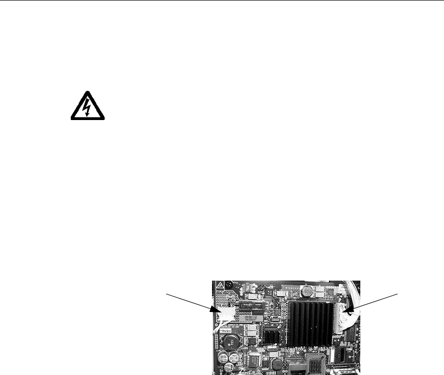
Chapter 4: Troubleshooting the PA PowerStation Replacing the SDRAM
PA PowerStation User Guide 61
Replacing the
SDRAM
To replace the SDRAM, complete the following steps. This procedure
requires opening up the back of the unit as well as removing the circuit
board. Be sure to follow the standard Electro-Static Discharge (ESD)
precautions.
Before you begin, turn off the power to the unit. Disconnect all cables.
Eject the CompactFlash card. Take off the clamps. And finally, place
the unit face down on an ESD mat.
Now you are ready to begin disassembling the unit.
1. Remove the screws from the back of the unit.
• For the 5" and 6" units, remove the 4 Phillips screws.
• For the 8" unit, remove the 6 Phillips screws.
• For the 10" unit, remove 6 Phillips screws. There are two on
each side and two on the bottom.
2. Disconnect the inverter cable and the video cable. See the
following picture.
3. To disconnect the inverter cable, slide it free of its connector.
4. To disconnect the video cable, lift it free of its connector.
5. Disconnect the ribbon connector. See the following picture.
Inverter cable Video cable
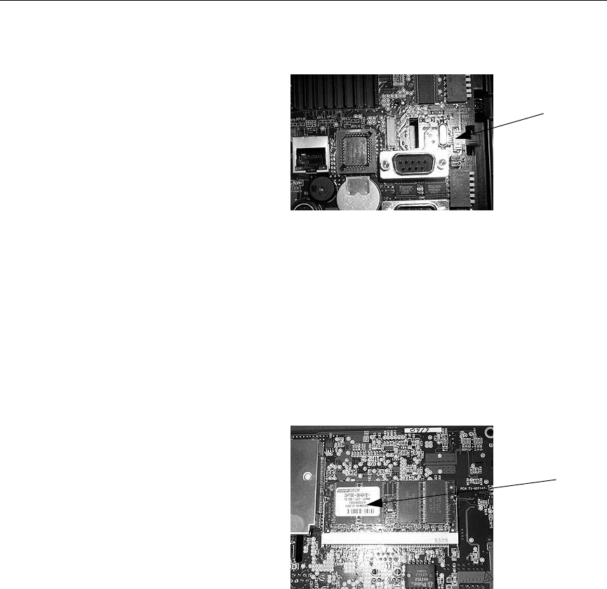
Replacing the SDRAM Chapter 4: Troubleshooting the PA PowerStation
62 PA PowerStation User Guide
6. To disconnect the ribbon, put your thumbs on the drawer tabs on
each side of the connector and slide the tabs out. In the above
picture, the tabs slide out to the right.
7. Remove the circuit board.
• For the 5" and 6", remove 4 stand-offs on the board.
• For the 8" and 10", remove 4 Phillips screws.
8. Lift the circuit board and turn it over to reveal the SDRAM. See the
following picture.
9. Push the ears out that hold the SDRAM in place.
10. With the bottom edge of the SDRAM still attached to the board, lift
the top edge of the SDRAM up to a 45 degree angle.
11. Slide it free.
12. Slide the new SDRAM into place at a 45 degree angle.
13. Press it down against the board, pushing the top edge of the
SDRAM until you hear the ears click into place.
SDRAM
Ribbon
connector

Chapter 4: Troubleshooting the PA PowerStation Replacing the SDRAM
PA PowerStation User Guide 63
14. Reattach the circuit board.
15. Reconnect the ribbon and push the drawer tabs back into place.
16. Reconnect the video cable and push the ears on the connector back
into place.
17. Reconnect the inverter cable.
18. Reattach the back of the unit.
19. Power on the unit.

Replacing the SDRAM Chapter 4: Troubleshooting the PA PowerStation
64 PA PowerStation User Guide


System Configuration Files Appendices
66 PA Series PowerStation User Guide
System Configuration Files
CTC Parker includes backup copies of the CONFIG.SYS File and AUTOEXEC.BAT File in the
\CTC directory on your PowerStation’s Compact Flash disk and on the PowerStation Start disk.
These files are called CONFIG.CTC and AUTOEXEC.CTC.
CONFIG.SYS File
SHELL=C:\COMMAND.COM /E:1024 /P
FILES=30
BUFFERS=30
STACKS=9,256
DEVICE=C:\DOS\HIMEM.SYS
DOS=HIGH,UMB
REM
REM !!! NOTE !!!
REM EMM386 can be used to free up more conventional memory for use by
REM Interact, by allowing TSRs to be loaded high. Just remove the word
REM 'REM' in front of the appropriate command, and adjust the
REM parameters as required for your system's configuration.
REM
REM DEVICE=C:\DOS\EMM386.EXE NOEMS
REM
REM IMPORTANT: Always include the NOEMS switch when using
REM EMM386 with Interact.
REM

Appendices System Configuration Files
PA Series PowerStation User Guide 67
AUTOEXEC.BAT File
@ECHO OFF
REM *********************************************************************
REM PA PowerStation Autoexec.bat
REM MachineShop Suite 1.05
REM Copyright (c) 2004 CTC Parker Automation
REM *********************************************************************
PROMPT $p$g
PATH C:\;C:\DOS;C:\CTC
SET TEMP=C:\DOS
REM *********************************************************************
REM Touchscreen configuration options
REM *********************************************************************
SET TOUCH_ADDR=3E8
SET TOUCH_IRQ=11
REM ********************************************************************
REM Set up Interact environment variables for MS Shell.
REM ********************************************************************
SET INTERACT=C:\INTERACT
SET INTERACT_FILES=C:\INTERACT\APPFILES
SET INTERACT_STARTUP=C:\STARTUP
REM ********************************************************************
REM Install PowerStation Special Functions
REM ********************************************************************
LH C:\CTC\BIOSTSR
REM ********************************************************************
REM Verify running on a PA PowerStation
REM ********************************************************************
C:\CTC\PACTRL -A -S
IF ERRORLEVEL 108 GOTO ERROR
REM ********************************************************************
REM If an external mouse is connected, MOUSE will install successfully
REM and create a new MOUSE.INI file.
REM ********************************************************************
CD \CTC
IF EXIST C:\CTC\MOUSE.INI DEL C:\CTC\MOUSE.INI
LH C:\CTC\MOUSE
REM ********************************************************************
REM Initialize touchscreen drivers.
REM ********************************************************************
SET TOUCH_PATH=C:\HAMMOUSE
CALL %TOUCH_PATH%\TS.BAT
REM ********************************************************************
REM Load NETWORK drivers -- NOVELL
REM Remove REM on the CALL statement to load NOVELL network batch file.
REM If used, this must be called BEFORE loading TCPIP.
REM ********************************************************************
CD \NET
REM CALL C:\NET\NET.BAT

System Configuration Files Appendices
68 PA Series PowerStation User Guide
REM ********************************************************************
REM Load TCP/IP Stack
REM ********************************************************************
LH C:\NET\TCPIP
REM ********************************************************************
REM Load scroll feature on quarter VGA system.
REM ********************************************************************
C:\CTC\PACTRL -T -S
IF ERRORLEVEL 3 LH C:\CTC\SCROLL
REM ********************************************************************
REM Call AUTOEXEC.BAT file contained in project, if it exists.
REM ********************************************************************
IF NOT EXIST C:\STARTUP\NUL.EXT MD C:\STARTUP
CD \STARTUP
IF EXIST C:\STARTUP\AUTOEXEC.BAT CALL C:\STARTUP\AUTOEXEC.BAT
REM ********************************************************************
REM Start the MachineShop Shell.
REM ********************************************************************
CD \CTC
PSU
GOTO END
:ERROR
CLS
ECHO.
ECHO This CompactFlash is programmed
ECHO for a PA PowerStation and is not
ECHO compatible with this system.
ECHO.
ECHO The startup process has been
ECHO halted.
ECHO.
:END

Index
P1 PowerStation User Guide 69
A
AC Power Supply 26
Guidelines 29
AUTOEXEC.BAT File 67
Command Line Parameters 51
B
Backlight bulb
replacing 25
BIOS Setup 42
C
Calibration Utility 44
Compact Flash
Using 47
CompactFlash 23
reformatting 49
replacing 25, 47
restoring 48
writing 48
CompactFlash, restoring 48
CONFIG.CTC 66
CONFIG.SYS File 66
Contrast, Adjusting the 46
Customer Support Services 5
D
Display Specifications 8
Display Unit
replacing 25
Documentation Components 3
Drive Definitions/Memory Map 24
E
Electrostatic Discharge 40
Ethernet Interface
Configuring the 53
Ethernet Port
Pinouts 22
Troubleshooting 60
F
Fuse, Replacing the 41
G
Getting Started 3
I
Installing
a Fuse 41
Installing the PowerStation
Cutout 31
Preparation 31
K
Keyboard Mouse Port 22
Connecting a PS/2 Mouse 22
M
MachineShop Shell
Troubleshooting 59
Using the Calibration Utility 44
Memory
Guidelines 24
Mode Settings
MODE.COM 20
To Adjust 20
Mounting Guidelines
Class 1, Division 2 28
Electrical 29
Enclosure 29
Environmental 28
Temperature 29
Mounting the PowerStation 33

Index
70 P1 PowerStation User Guide
O
Optional Components 26
P
PA Series PowerStation
Documentation Set 3
Release Notes 3
Template 3
User Guide 3
Parallel Port
Pinouts 22
Physical Specifications 9
PowerStation
See PA Series PowerStation
PowerStation Utilities
reinstalling 48
Printing
Printing to a Port Configured for
Downloading 21
R
Replacement Components 25
Resolving Problems 55
ROM-DOS
Troubleshooting 59
S
SDRAM, replacing 61
Serial Cable Diagrams
RS-232 18
RS-422 18
RS-485 18
Serial Ports 14
COM1 Pinouts 15
COM2 Dip Switch Settings 17
COM2 pinouts 16
Serial Printer
Cable Diagram 20
Connecting to 20
Software Components 3
Specifications
Display 8
5" 8
8" 9
Physical 9
Splash screen
removing 42
T
TCP/IP Settings 19
Touchscreen
Cleaning the 43
Maintaining the 43
replacing 25
Troubleshooting 57
Transferring Files from a PC to the
PowerStation 18
Troubleshooting
AUTOEXEC.BAT 57, 58, 59, 67
CONFIG.SYS 57, 66
Ethernet Port 60
LED Power Indicator 56
PS/2 Mouse 59
Serial Mouse 60
Touchscreen 57
U
Underwriters Laboratories 29
W
Wiring Requirements 29
