MSD 7230 Ignition Kit Installation Instructions 121
User Manual: 7230
Open the PDF directly: View PDF ![]() .
.
Page Count: 12
MSD 7AL-3, Ignition Control
PN 7230
Important: Read the instructions before attempting the installation.
Parts Included:
1 - 7AL-3, PN 7230
1 - Parts Bag (wires and connectors)
4 - RPM Modules 3000, 7000, 8000, 9000
4 - Retard Modules 2°, 3°, 4°, 4°
4 - Zero Degree Modules
4 - Vibration Mounts
WARNING: During installation, disconnect the battery cables. When disconnecting the battery,
always remove the Negative cable first and install it last.
Note: The MSD 7AL-3 will retard the ignition timing approximately 4° compared to other MSD Ignitions.
After installation, the timing should always be checked and adjusted at idle and total timing.
Note: This unit is designed for 8-cylinder engines only.
COIL RECOMMENDATIONS
The MSD 7AL-3 can be used with a variety of coils, but to receive the best performance, it is
recommended to use an MSD Coil. For drag racing and “short duration” applications, the Pro Power
Coil, PN 8201, is the best choice. For street applications or long duration racing events, the HVC Pro
Power Coil, PN 8251 is recommended. The 7AL-3 may be used with a GM HEI Distributor with an
internal coil, however the Rotor Bushing must be replaced with an MSD Low Resistance Bushing,
PN 8412.
MOUNTING
The 7AL-3 can be mounted under the hood, but should be mounted in a position away from direct
engine heat sources. Use the ignition as a template and mark the location of the mounting holes.
Remove the unit and drill the holes using a 1/4" bit. Install the vibration mounts to the 7AL-3 then
mount the ignition using the supplied lock washers and nuts.
WIRING
Wiring the 7AL-3 will be simple by following the instructions. There are several color coded wires
supplied with the 7AL-3 and should be used as noted to avoid confusion or wrong connections. This
section is also broken down into two sections; Primary Wiring and Optional Wiring.
• The Primary section designates the wires that must be connected to run the engine.
• The Optional Wiring section explains the wiring of optional built-in features such as the Rev Controls,
RPM Activated Switch and Retard Controls.
WARNING: The 7AL-3 produces very high voltages. Never short the battery or coil terminals. Use
caution during installation and while working near the ignition.
MSD IGNITION • www.msdignition.com • (915) 857-5200 • FAX (915) 857-3344

2
INSTALLATION INSTRUCTIONS
MSD IGNITION • www.msdignition.com • (915) 857-5200 • FAX (915) 857-3344
PRIMARY WIRING
WARNING: During installation, disconnect the battery cables. When disconnecting the battery,
always remove the Negative cable first and install it last.
1. Begin wiring the MSD by connecting the wires responsible to run the engine. The terminal strip on
the left side of the box is responsible for the Power Leads and the Coil Wires. Connect the supplied
wires as follows:
Heavy Red: Connect from the “Batt +” terminal directly to the battery positive (+) terminal.
Heavy Black: Connect from the “Batt -” terminal directly to the battery negative (-) terminal.
Orange: Connect from the “Coil +” terminal to the positive terminal (+) of the coil.
Black: Connect from the “Coil -” terminal to the negative terminal (-) of the coil.
2. Move to the middle terminal strip and locate the terminal marked “Ignition”. Use the supplied RED
wire and connect it to a switched 12 volt source (ignition switch).
3. If a retard function is not going to be used the supplied "zero" degree module must be installed or
the terminals must be grounded. See the Multi-Step Retard Section.
4. The three terminals on the bottom of the middle terminal strip receive the trigger signal from the
distributor. One terminal is for points style applications and the other two are for use with a magnetic
pickup trigger, such as an MSD Billet Distributor or Crank Trigger.
Note: The Points and Mag Pickup terminals will never be connected at the same time.
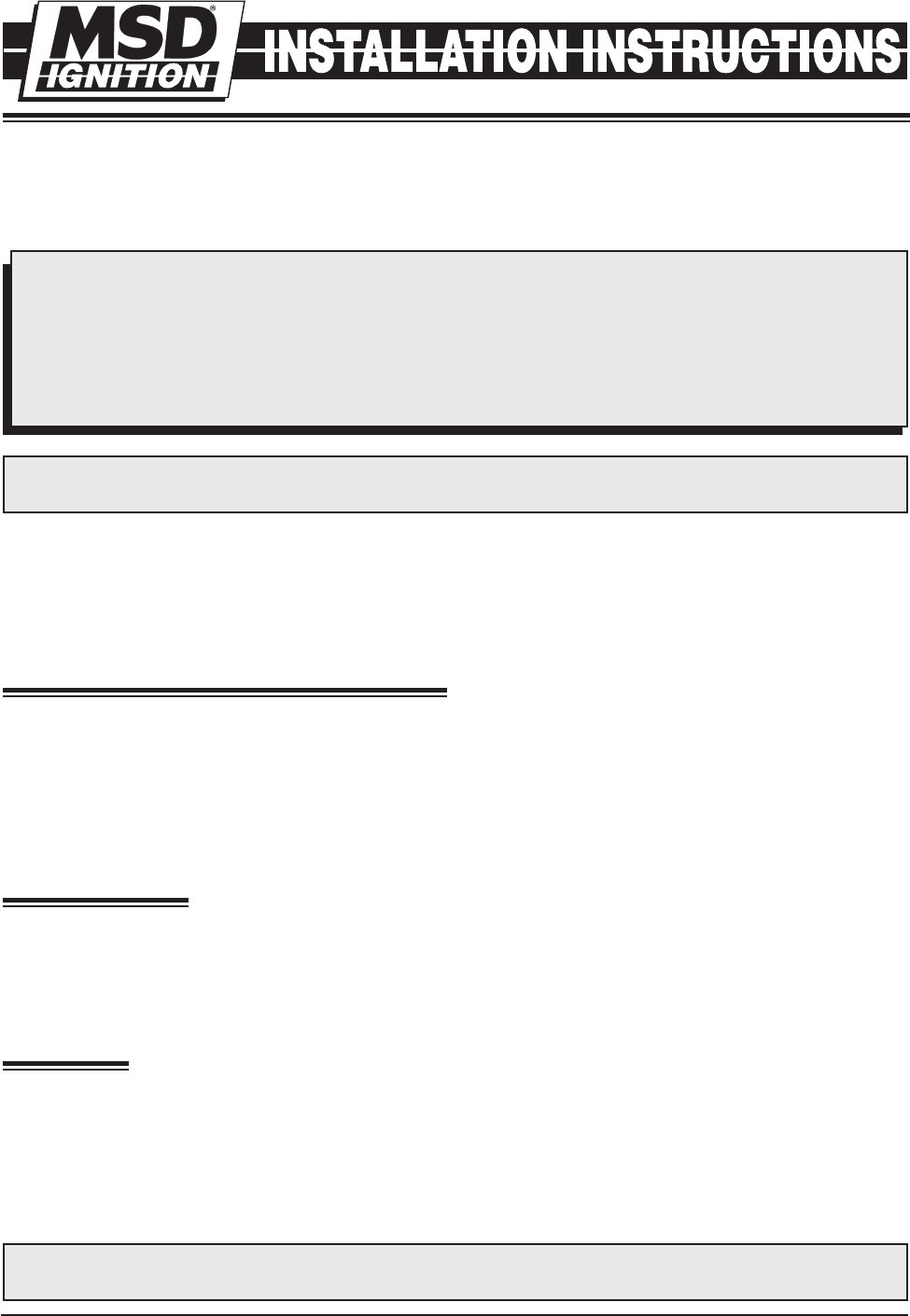
Points: If you are using a Points style distributor or electronic amplifier, only the “Points” terminal
will be used. Connect the supplied WHITE jumper wire from the points output in the distributor to
the “Points” terminal (Figure 1).
Magnetic Pickup: If you are using an MSD Distributor or Crank Trigger, only the Magnetic Pickup
terminals will be used. Locate the supplied harness with a VIOLET and GREEN wire with a 2-pin
connector on one end. Connect the VIOLET wire to the “Mag +” terminal and the GREEN wire to the
“Mag -” terminal then connect the 2-pin connector to the Distributor (Figure 1).
Note: The magnetic pickup wires must be routed away from all voltage carrying wires. A shielded
6-feet harness is available as PN 8862.
MAGNETIC PICKUP POLARITY
The MSD 7AL-3 can be used with other magnetic
pick-up distributors as long as the wires are
connected correctly. The chart on the right shows
the polarity of some common magnetic pickups.
Common Mag Pickup Wires
Distributor Colors
Mag+ Mag-
MSD Org/Blk Vio/Blk
MSD Crank Trigger Violet Green
Ford Orange Purple
Accel 46/48000 Series Org/Blk Vio/Blk
Accel 51/61000 Series Red Black
Chrysler Org/Wht Black
Mallory Org/Blk Vio/Blk
I
NSTALLATION INSTRUCTIONS 3
MSD IGNITION • www.msdignition.com • (915) 857-5200 • FAX (915) 857-3344
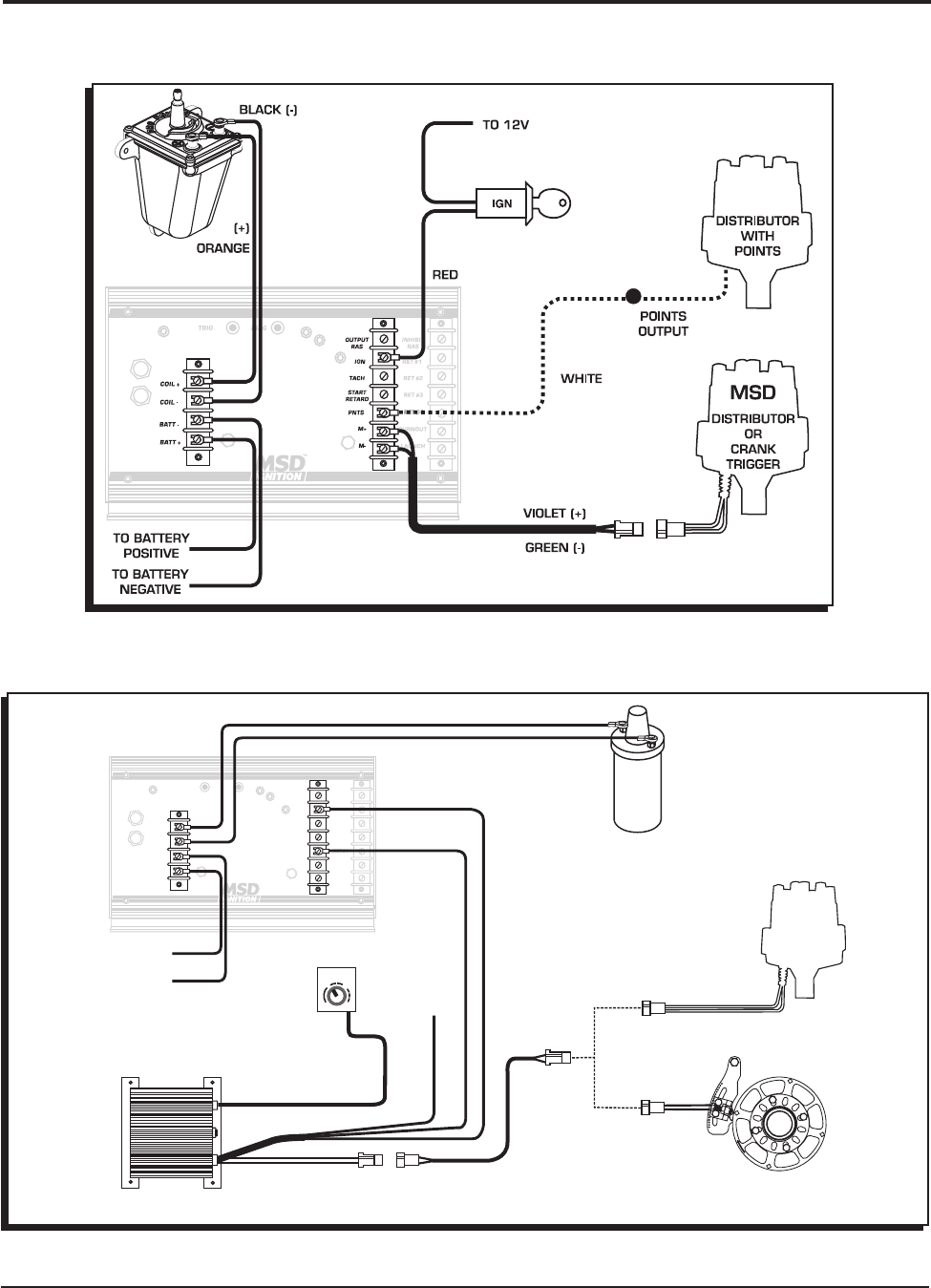
Figure 2 Primary Wiring to an MSD Timing or Boost Control and a Magnetic Pickup.
Figure 1 Wiring the Primary Side of the Ignition to Points or Magnetic Pickup.
RETARD
0
12
3
OR
GREEN
VIOLET
DISTRIBUTOR
WITH
MAGNETIC PICKUP
NOTE: THIS DIAGRAM
ILLUSTRATES HOW TO
INSTALL ANY MSD
TIMING CONTROL.
MSD CRANK
TRIGGER WHEEL
MAGNETIC PICKUP
CONNECTOR
WHITE
NOT USED
RED
YELLOW
INHIBIT
RAS
OUTPUT
RAS
IGN
TACH
START
RETARD
PNTS
M+
M-
RET #1
RET #2
RET #3
RET #4
LAUNCH
BURNOUT
COIL +
TRIG DIAG
COIL -
BATT -
BATT +
TM
TO BATTERY
NEGATIVE
TO BATTERY
POSITIVE
MSD
DISTRIBUTOR
ORANGE (+)
BLACK (-)
COIL
4
INSTALLATION INSTRUCTIONS
MSD IGNITION • www.msdignition.com • (915) 857-5200 • FAX (915) 857-3344
Note: The MSD 7AL-3 will retard the ignition timing approximately 4° compared to other MSD Ignitions.
After installation, the timing should always be checked and adjusted at idle and total timing.
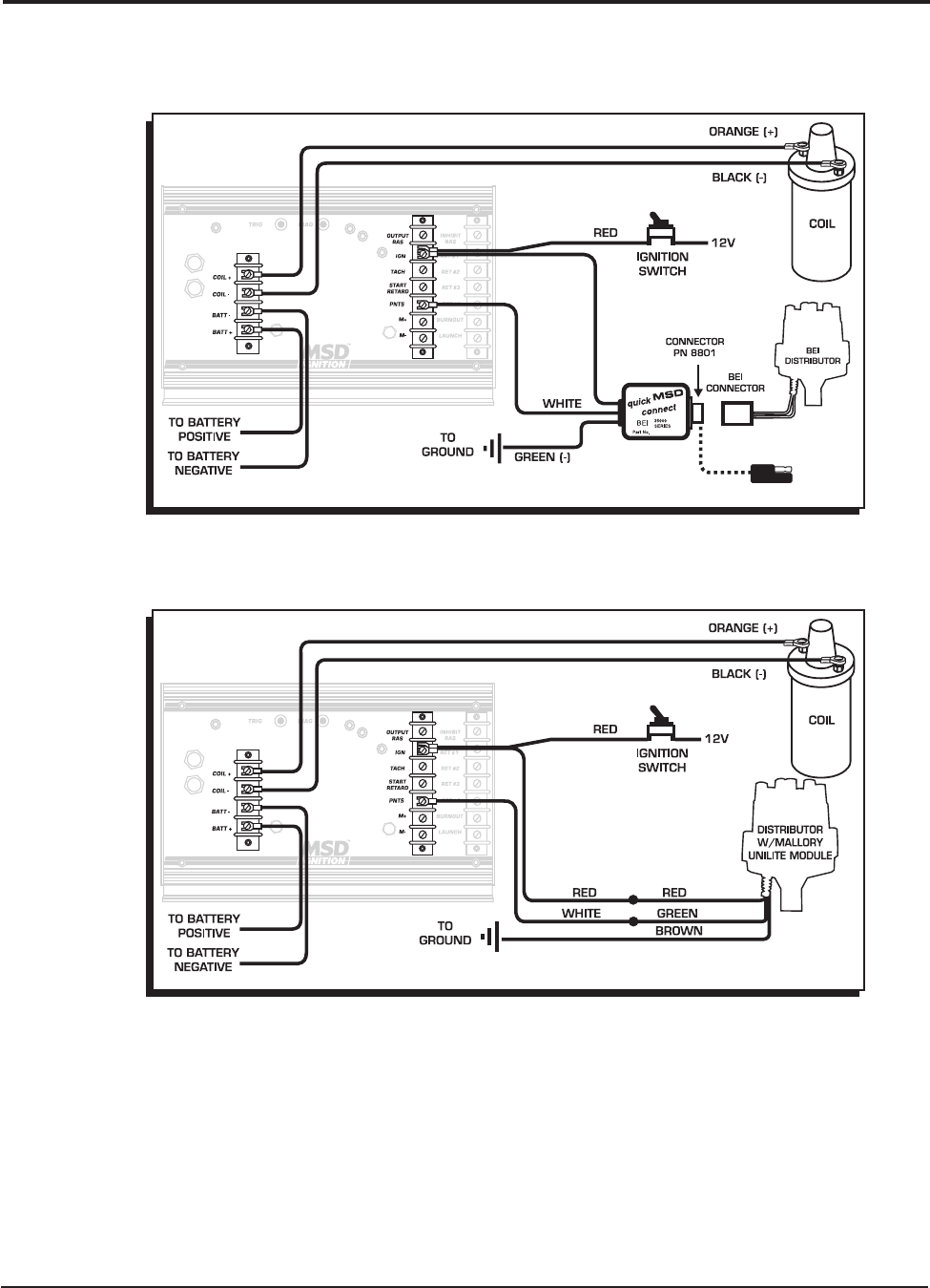
The following diagrams show the installation to a Mallory and an Accel BEI distributor.
Figure 3 Primary Wiring to an Accel BEI Distributor.
Figure 4 Primary Wiring to a Mallory Unilite Distributor.
NOTE: ALL 3-WIRE MALLORY DISTRIBUTORS CONNECT THIS WAY.
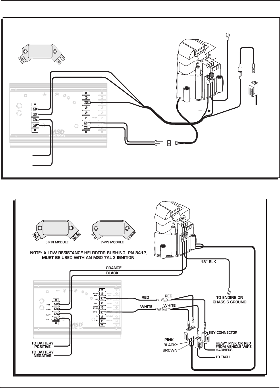
GM HEI DISTRIBUTOR
The 7AL-3 can be wired to the GM HEI Distributor. You must identify which module your distributor has
to determine which wiring diagram to use. Count the number of pins or terminals on the module.
I
NSTALLATION INSTRUCTIONS 5
MSD IGNITION • www.msdignition.com • (915) 857-5200 • FAX (915) 857-3344
Figure 6 Primary Wiring to a GM HEI with a 5 or 7-Pin Module (Points Trigger).
Figure 5 Primary Wiring to a GM HEI with a 4-Pin Module (Magnetic Pickup Trigger).
INHIBIT
RAS
OUTPUT
RAS
IGN
TACH
START
RETARD
PNTS
M+
M-
RET #1
RET #2
RET #3
RET #4
LAUNCH
BURNOUT
COIL +
TRIG DIAG
COIL -
BATT -
BATT +
TM
TO BATTERY
NEGATIVE
TO BATTERY
POSITIVE
4-PIN MODULE
NOTE: A LOW RESISTANCE HEI ROTOR
BUSHING, PN 8412, MUST BE USED
WITH AN MSD 7AL-3 IGNITION.
PN 8861
HARNESS
(THIS HARNESS
IS AVAILABLE
FROM MSD)
GREEN M-
VIOLET M+
BLACK
RED
BLACK
RED
18" BLK
ORANGE
ORANGE
KEY
CONNECTOR
WHITE
JUMPER
TO ENGINE OR
CHASSIS GROUND
HEAVY RED
OR PINK WIRE
FROM CAR
WIRING HARNESS
NOTE:MODULE AND WIRING
NEEDS TO BE REMOVED.
6
INSTALLATION INSTRUCTIONS
MSD IGNITION • www.msdignition.com • (915) 857-5200 • FAX (915) 857-3344
OPTIONAL WIRING
This Wiring Section details the optional features of the MSD 7AL-3 and how to wire each system.
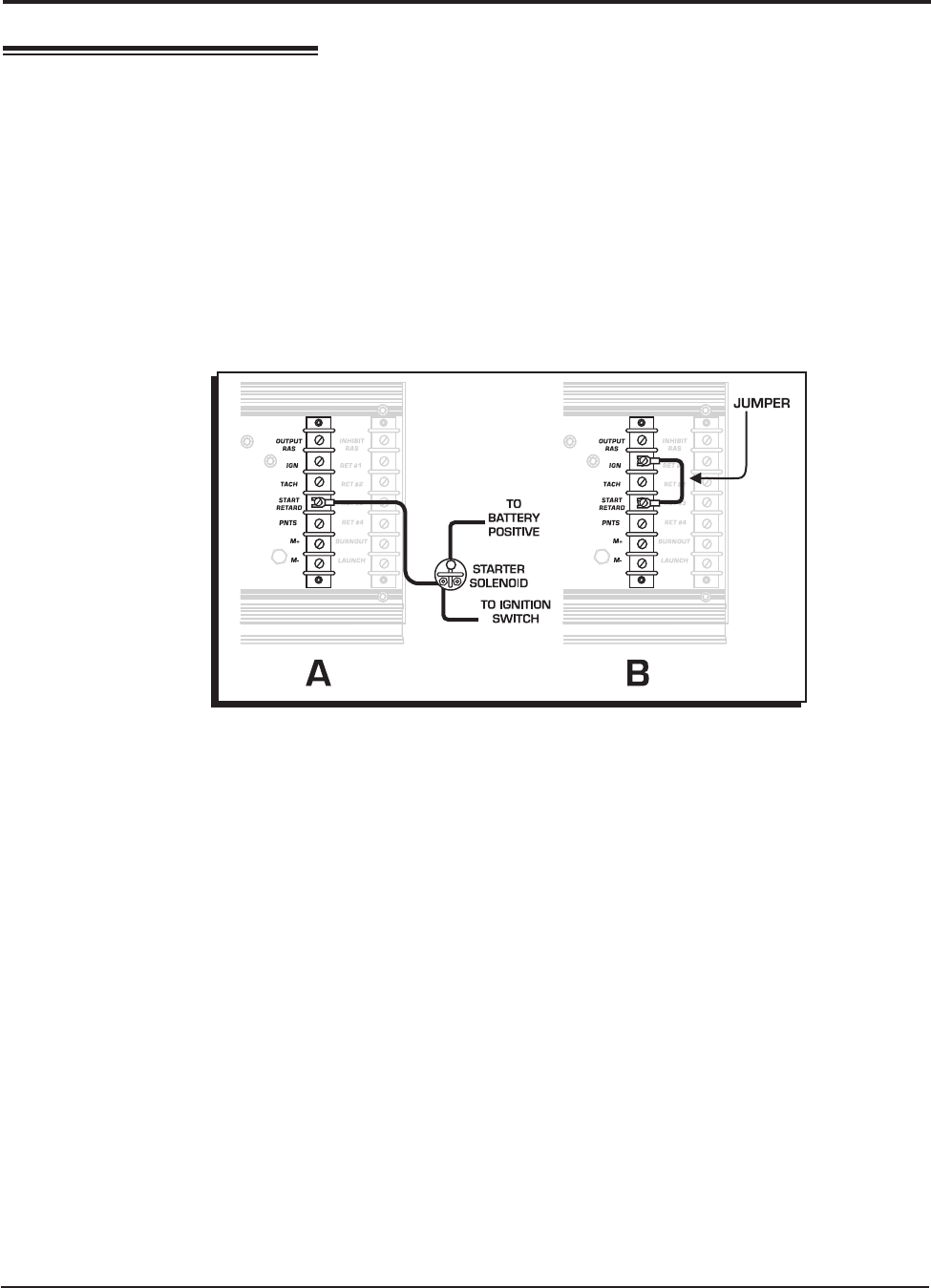
START RETARD
The Start Retard of the 7AL-3 is designed to ease starting on engines with locked timing, high
compression and a lot of advance. When activated, the timing is retarded 25°. Some engine
combinations benefit from this retard, while others may experience rough starting or starter kickback.
If your engine experiences roughness with the start retard engaged, the retard is not necessary.
When activated, the Start Retard function will retard the ignition timing 25° while the engine is cranking
which makes starting easier as well as saves wear and tear on the engine and the starter. This retard
function will only operate below approximately 1,300 rpm. There are two different ways to connect
this function (Figure 7):
A. Switched 12 Volts
In this set up, the timing is retarded 25° only while the engine is cranking. Connect the supplied Violet
wire from the “Start-Ret” terminal on the 7AL-3 to the starter solenoid. This way, 12 volts is only applied
when the key or switch is in the cranking position. When the switch is released, 12 volts is removed
and the timing returns to run timing.
B. Constant 12 Volts
In this setup, whenever the ignition is turned On, 12 volts is applied and the retard function is activated.
The retard will be deactivated when the engine reaches about 1,300 rpm and will not occur again
until the ignition is turned Off. Connect the supplied jumper from the Start-Ret terminal to the Ignition
terminal of the terminal strip (two terminals up).
THREE STEP RPM LIMITS
The 7AL-3 has a built-in Three Step Module Selector which allows you to select up to three different
rpm limits that occur at different times. The activation terminals are located on the bottom of the
third terminal strip and are listed as Launch and Burnout. The third rpm limit is the high rpm, which
is always active when there is an rpm module installed in the "Race" holder (except when the other
rpm limits are activated).
These modules can be used in a variety of functions and are not limited to launches and burnouts.
Each of the two optional rpm limits are activated when 12 volts is applied to their corresponding
terminals (Figure 8). The 12 volts can come from switches, solenoids or relays giving you a variety of
ways to activate the different rpm limits. The following steps illustrate a general drag race installation
for use with a Burnout limit, Launch limit and Race limit.
Figure 7 Wiring the Start Retard Function.
I
NSTALLATION INSTRUCTIONS 7
MSD IGNITION • www.msdignition.com • (915) 857-5200 • FAX (915) 857-3344
Note: Since the 7AL-3 is primarily a drag race ignition, the Launch limit is designed to override the
Race and Burnout limits, even if the Burnout limit is activated at the same time.
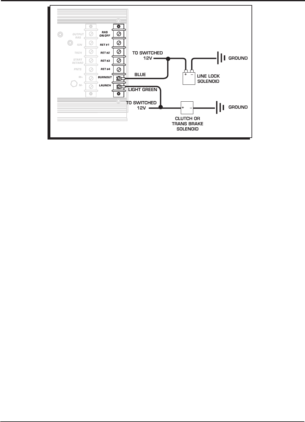
Connecting the Three Step Function
1. Connect the supplied Blue wire from the Burnout terminal of the MSD to the 12 volt activation wire
of the line lock solenoid. With this setup, when the line lock is activated, 12 volts will be supplied
to the Burnout terminal which limits the rpm to your specified burnout rpm module.
2. Connect the supplied Light Green wire to the Launch terminal of the MSD then splice it into the
clutch or trans brake 12 volt activation wire. This way, when the clutch pedal is depressed, 12 volts
is applied to the Launch terminal which limits the rpm to your specified launch rpm module.
Note: The Launch rpm limit is designed to override the Burnout limit. This way, if you activate the
line-lock on the starting line, when the Launch terminal is activated through the trans brake or
clutch switch, the Launch rpm (not the Burnout limit) will be in effect. After the car launches
the Race rpm limit is activated to protect the engine from over revving.
RPM ACTIVATED SWITCH
The RPM Activated Switch (RAS) Output will turn on a component such as a shift light or nitrous solenoid
at an adjustable rpm point by supplying a ground path. The RPM Switch is capable of handling a 10
amp load. If 12 volts is required to activate the component, use an MSD Relay, PN 8960 or 8961.
The 7AL-3 also features an "RAS On/Off" for the RPM Activated Switch. To use the RPM Switch, 12
volts must be connected to the “RAS-On/Off” terminal located at the top of the third terminal strip.
Whenever the 12 volts is removed from this terminal, the RPM Activated Switch will not operate.
Figure 8 Connecting the Three Step Module Selector.
8
INSTALLATION INSTRUCTIONS
MSD IGNITION • www.msdignition.com • (915) 857-5200 • FAX (915) 857-3344
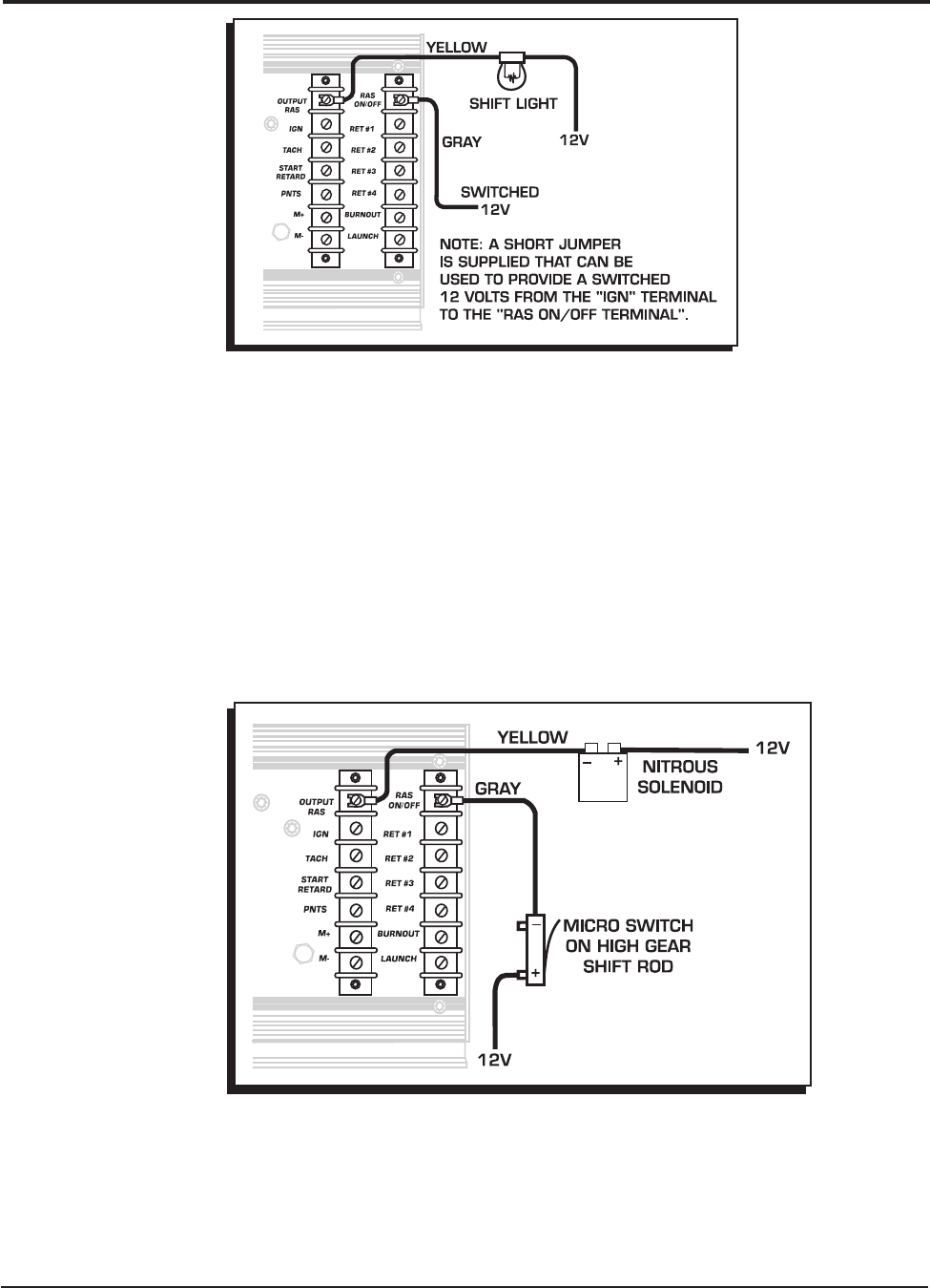
Basic Wiring: This example illustrates how to connect the RAS to activate a shift light at 7,000 rpm
(Figure 9).
1. Connect the Gray wire to the RAS On/Off terminal and to a switched 12 volt source. This "prepares"
the RAS circuit so when the desired rpm is reached the "Output Ras" will provide a ground to activate
the light. A jumper is supplied to connect the "IGN" terminal to the RAS ON/OFF.
2. Connect the Yellow wire to the "RAS Output" terminal and the other end to the ground side of the
shift light. Note: Twelve volts must be connected to the other side of the light.
3. Place a 7,000 rpm module in the RAS plug. When the engine reaches 7,000 rpm, a ground path
for the shift light will be supplied and the light will turn on. Note: The light will remain on until the
rpm falls 5% below the amount of the module. When you shift, the rpm drops and the light turns
off until 7,000 rpm, when a ground path is again provided and the light turns on.
Incorporating the RAS On/Off: With the "RAS On/Off" terminal, you can control exactly when the
RPM Switch is activated. This example illustrates how to turn on a nitrous solenoid at 5,000 rpm, but
only when the car is in high gear (Figure 10). To do this, 12 volts must be applied to the "RAS On/Off"
terminal only during high gear. This can be accomplished with a micro switch on the shifter.
Figure 9 Connecting the RPM Activated Switch.
Figure 10 Activating the RAS in High Gear Only.
I
NSTALLATION INSTRUCTIONS 9
MSD IGNITION • www.msdignition.com • (915) 857-5200 • FAX (915) 857-3344
1. Connect the Gray wire from the "RAS On/Off" terminal, to a micro switch that will close only when
high gear is activated. The other side of the switch must have 12 volts.
2. Connect the supplied Yellow wire from the “Output RAS” terminal located at the top of the middle
terminal strip, to the ground side of the nitrous solenoid. When the engine reaches 5,000 rpm in
high gear, a ground path will be provided to the solenoid.
3. During the range of lower gears, even when the engine reaches over 5,000 rpm, the solenoid will
not activate. When high gear is activated, the micro switch closes and 12 volts is applied to the
"RAS On/Off" terminal which prepares the "Output RAS". The "Output RAS" provides a ground circuit
for the nitrous solenoid. Note: The solenoid will remain activated until the micro switch removes
the 12 volts from the "RAS On/Off" or until the rpm falls 5% below 5,000 (or whatever module is
installed).
MULTI-STEP RETARD
There are four retard modules available with the 7AL-3. Each module is activated independently
by removing ground from the corresponding module. The controlling terminals are listed as RET-1
through RET-4 and are located on the third terminal strip. The modules can be activated in any order
and are cumulative unless deactivated. The maximum amount of retard allowed is a total of 20° even
if the modules add up to more than 20°.
Note: If a Retard function is not going to be used the corresponding terminals must be grounded,
or a "zero" degree module must be installed.
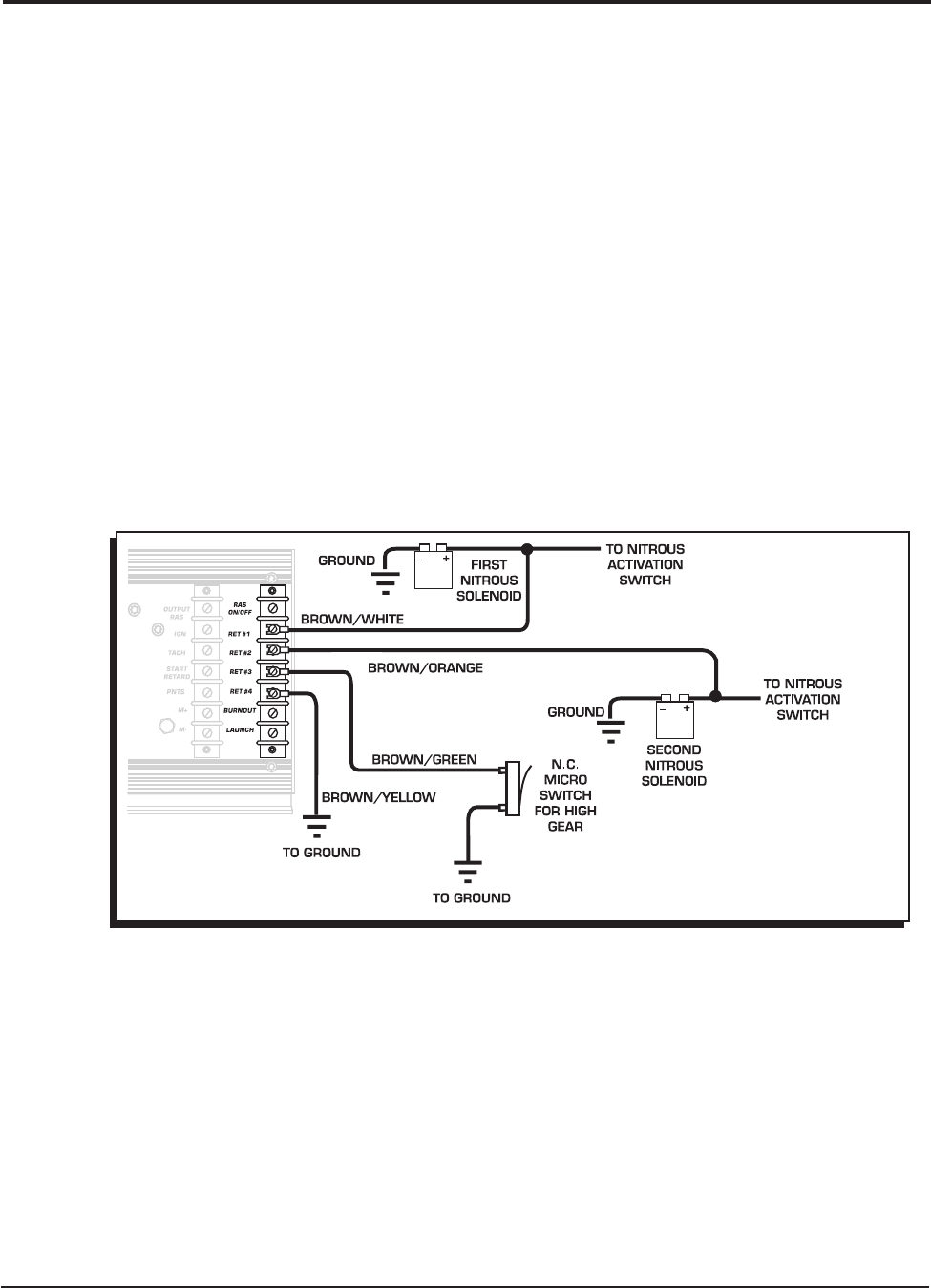
Connecting the Multi-Step Retard Function
In this example, we will connect three of the four retard modules (Figure 11). One to the first nitrous
solenoid, another to the second nitrous solenoid and a third for a high speed retard that engages
when high gear is pulled.
Note: By connecting to the 12 volt source side of the nitrous solenoid, the wire receives ground
through the windings of the solenoid.
1. Connect the supplied Brown/White wire from the RET-1 terminal to the 12 volt source side of the
number one nitrous solenoid. With the solenoid not activated, the wire will be grounded through
the solenoid. When 12 volts is applied to activate the solenoid, the ground will be removed which
will activate RET-1.
Figure 11 Connecting the Multi-Step Retard.
NOTE: RET4 IS NOT USED, SO A "zERO"
DEgREE MODULE MUST BE INSTALLED
IN MODULE #4 OR THE TERMINAL
MUST BE gROUNDED.
10
INSTALLATION INSTRUCTIONS
MSD IGNITION • www.msdignition.com • (915) 857-5200 • FAX (915) 857-3344
2. Connect the Brown/Orange wire from the RET-2 terminal to the 12 volt source side of the number
two nitrous solenoid. When the second solenoid is activated the ground is removed and the RET-2
module is activated.
Note: Since the number one solenoid remains on, the first and second retard modules are now
activated and their retard amounts are added together.
3. To activate RET-3, the Brown/Green wire is connected from the RET-3 terminal to a normally closed
(N.C.) microswitch on the shifter. When the shifter is pulled into high gear, the switch removes the
wire from ground which activates the third retard. The total sum of the three retard amounts are
now activated.
4. Since RET-4 is not being used, a "zero" degree module must be installed, or the terminal must be
grounded.
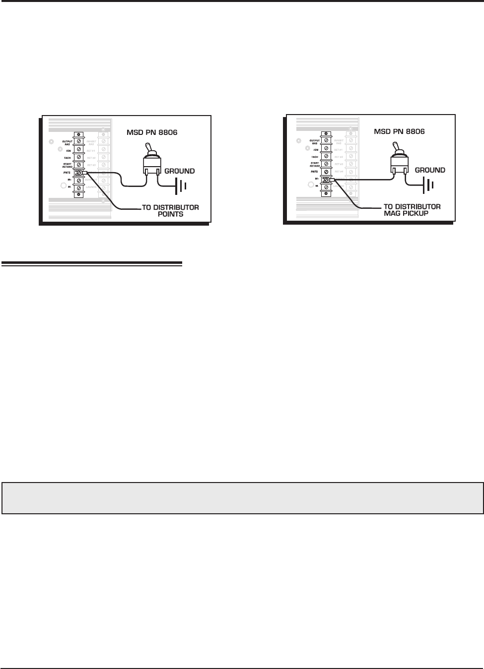
Figure 13 Connecting a Tachometer.
TACHOMETER
This terminal provides a square wave 12 volt, 20% duty
cycle signal for your tachometer. Use the supplied Brown
wire and connect it to the Tach terminal strip (Figure 13). If
your tachometer reads erratic or does not operate properly,
a Tach Adaptor may be required. If you are using the white
wire to trigger (points input) you will need Adapter PN 8910.
If you are using the magnetic pickup, PN 8920 will be the
right Adapter. Contact your MSD dealer.
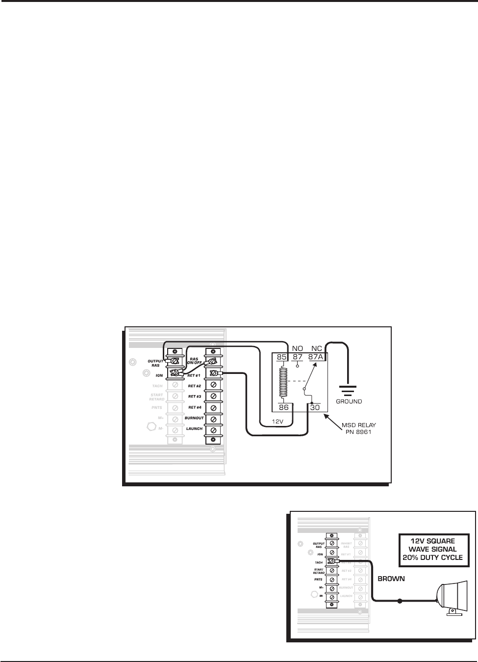
RETARD WITH THE RPM ACTIVATED SWITCH
The MSD 7AL-3 has both an RPM Activated Switch (RAS) and a Multi-Step Retard. The stages of
retard are activated when the corresponding activation wire is removed from ground. The RAS can
only activate a circuit by providing a ground path.
If you want to use the RAS to activate a retard stage of the 7AL-3, an external relay must be used. The
MSD Relay, PN 8961, is supplied in the parts bag with the 7AL-3. Figure 12 shows how to connect the
relay for this application. RET 1 is grounded through terminals 30 and 87A of the Relay while the relay
is off. Terminal 86 receives 12 volts from the ignition terminal and when the desired rpm is activated,
a ground path is supplied to terminal 85 which turns the relay On, activating the retard.
Note: Make sure 12 volts is applied to the RAS On/Off terminal.
NOTE: THE RELAY IS SHOWN
IN THE DE-ENERGIZED
POSITION.
Figure 12 Using the RAS to Activate a Retard.
I
NSTALLATION INSTRUCTIONS 11
MSD IGNITION • www.msdignition.com • (915) 857-5200 • FAX (915) 857-3344
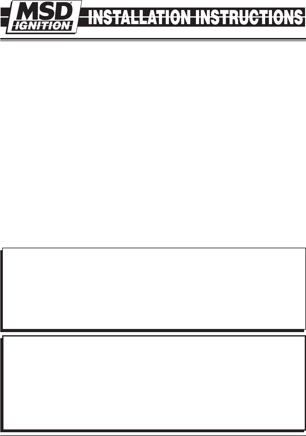
KILL SWITCH
If your racing application requires an ignition kill switch (dead man's switch) it is easy to incorporate
into the ignition's trigger input wire. When the trigger input terminal is grounded, the ignition is killed.
A Single-Pole, Single Throw Switch is required (MSD PN 8806).
Points: Connect one side of the switch to ground and the other side to the Points terminal of 7AL-3
(Figure 14).
Mag Pickup: Connect one side of the switch to ground and the other side to the Mag+ terminal of
7AL-3 (Figure 15).
TROUBLESHOOTING
If for some reason you suspect that the ignition system is not functioning properly, follow the proceeding
procedures to determine if the MSD is functioning properly.
DIAGNOSTIC LED
The MSD 7AL-3 is equipped with two LEDs; one Green, one Red.
Green: The Green LED indicates that the ignition is operating properly and is receiving a trigger
signal. If it is not operating, the trigger mechanism, either crank trigger or distributor, is not delivering
a trigger signal. If the engine will not run though the Green LED shows a trigger signal, follow the
"Checking for Spark" procedure on page 12.
Red: The Red LED is a safety or warning function. If it turns on, a problem within the ignition is
occurring. If the Red Led is on, inspect the wiring and connections. If everything checks okay, the
ignition needs to be sent to the factory for inspection/repairs.
MSD offers an Ignition Tester, PN 8998, that will check the Ignition and Coil's operation.(The obsoleted
Tester PN 8995, can only be used on the points input.)
WIRING CHECK
WARNING: The 7AL-3 produces very high voltages. Never short the battery or coil terminals. Use
caution during installation and while working near the ignition.
• Check all of the wire connections making sure they are clean and tight. If connectors have been
crimped on make sure they are tight and sealed.
• Make sure the battery is fully charged and properly connected. Also confirm that the MSD power
leads are connected properly and are tight.
• With a test light check that there is voltage on the RED “Ignition” terminal of the MSD when the
ignition is in both the On and START position.
• Check that the only wires connected to the coil are from the MSD. ORANGE should connect to
the positive terminal, BLACK to the negative terminal.
Note: DO NOT connect any test equipment to the coil terminals.
After checking the wiring for loose or faulty connections, follow the next steps to confirm that the unit
is “sparking” properly.
Figure 14 Connecting a Kill Switch to Points. Figure 15 Connecting the Kill Switch to the Mag+.
CHECKING FOR SPARK
The following procedures will determine if the ignition is producing a spark. Before proceeding, inspect
all of the wiring and ensure that the Green LED is flashing when the engine is cranked. This ensures
that the ignition is receiving a trigger signal .
Magnectic Pickup (Green and Violet):
1. Make sure the ignition is turned OFF and remove the coil wire from the distributor cap. Pull the
boot back so the terminal is easy to see and position the wire 1/2" from ground.
2. Disconnect the magnetic pickup connector from the distributor.
3. Turn the ignition switch to the ON position. DO NOT CRANK THE ENGINE.
4. Take a short lengh of wire and short the Green and Violet wires together then pull the wire away.
A spark should jump from the coil wire to ground every time the connection is broken.
5. If there is no spark, substitute another coil and test again. If there is still no spark and all of the
wiring connections have been confirmed, contact the MSD Customer Service Line and send the
unit in for repair.
White Wire Trigger:
1. Make sure the ignition is turned OFF and remove the coil wire from the distributor cap. Pull the
boot back so the terminal is easy to see and position the wire 1/2" from ground.
2. Disconnect the White wire from the distributor.
3. Turn the ignition switch to the ON position. DO NOT CRANK THE ENGINE.
4. Tap the White wire to ground several times. A spark should jump from the coil wire to ground when
the white wire is removed from ground.
5. If there is no spark, substitute another coil and test again. If there is still no spark and all of the
wiring connections have been confirmed, contact the MSD Customer Service Line and send the
unit in for repair.
Limited Warranty
M
SD IGNITION warrants this product to be free from defects in material and workmanship under its intended normal
use*, when properly installed and purchased from an authorized MSD dealer, for a period of one year from the date
of the original purchase. This warranty is void for any products purchased through auction websites. If found to be
defective as mentioned above, it will be repaired or replaced at the option of MSD Ignition. Any item that is covered
under this warranty will be returned free of charge using Ground shipping methods.
This shall constitute the sole remedy of the purchaser and the sole liability of MSD Ignition. To the extent permitted
by law, the foregoing is exclusive and in lieu of all other warranties or representation whether expressed or implied,
including any implied warranty of merchantability or fitness. In no event shall MSD Ignition or its suppliers be liable
for special or consequential damages.
*Intended normal use means that this item is being used as was originally intended and for the original application
as sold by MSD Ignition. Any modifications to this item or if it is used on an application other than what MSD Ignition
markets the product, the warranty will be void. It is the sole responsibility of the customer to determine that this item
will work for the application they are intending. MSD Ignition will accept no liability for custom applications.
Service
In case of malfunction, this MSD component will be repaired free of charge according to the terms of the warranty.
When returning MSD components for warranty service, Proof of Purchase must be supplied for verification. After
the warranty period has expired, repair service is based on a minimum and maximum fee.
All returns must have a Return Material Authorization (RMA) number issued to them before
being returned. To obtain an RMA number please contact MSD Customer Service at 1 (888) MSD-7859 or
visit our website at www.msdignition.com/rma to automatically obtain a number and shipping information.
When returning the unit for repair, leave all wires at the length in which you have them installed. Be sure to include
a detailed account of any problems experienced, and what components and accessories are installed on the vehicle.
The repaired unit will be returned as soon as possible using Ground shipping methods (ground shipping is covered
by warranty). For more information, call MSD Ignition at (915) 855-7123. MSD technicians are available from 7:00
a.m. to 6:00 p.m. Monday - Friday (mountain time).
MSD IGNITION • www.msdignition.com • (915) 857-5200 • FAX (915) 857-3344
© 2007 Autotronic Controls Corporation
FRM28912 Revised 08/07 Printed in U.S.A.
