SpeedZone_Sport Speed Zone Sport Bicycle Computer Speedzone 07 Instruction Guide
User Manual: SpeedZone Sport Bicycle
Open the PDF directly: View PDF ![]() .
.
Page Count: 10
1
english
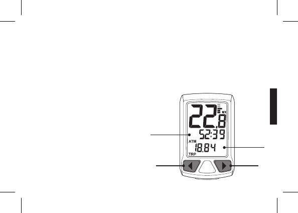
SPEEDZONE SPORT CYCLOCOMPUTER
PREV KEY NEXT KEY
MIDDLE LINE
LOWER LINE
Congratulations on your purchase and welcome to the growing number of cyclists who are discovering a powerful new
generation of bicycle computers. Your Specialized SpeedZone Sport Cycle Computer has been designed to provide the
best combination of performance, features, durability and ease of use and installation.
This manual is an important part of your SpeedZone Cycle Computer. To get the most enjoyment out of your SpeedZone
Cycle Computer, please read all sections carefully and reference it when preforming the initial programming and operation
of the unit. Once you are familiar with all functions of your SpeedZone Cycle Computer, store this manual in a safe location
for future reference.
SPEEDZONE SPORT FEATURES
• Time of Day
• Odometer
• Wheel Size Settings
• Speed
• Average Speed
• Maximum Speed
• Individual Trip Distance (TRP)
2
english
3
english
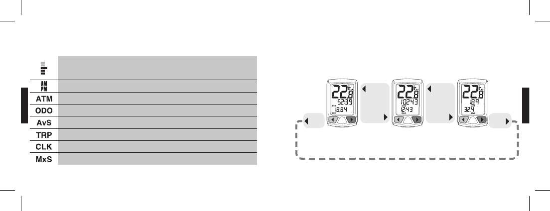
symbol description what it means
MULTI-STAGE SPEED
COMPARATOR
Indicates whether current speed is greater than, less than or equal to
the average calculated speed. One bar shown means average speed is
0-2.5 mph/kph above/below calculated average speed.
AM/PM AM or PM time ( 12 hour mode only)
RIDE TIME Total ride time is displayed
ODOMETER Odometer mode is active
AVERAGE SPEED Average speed is displayed
TRIP Trip distance is displayed
CLOCK Time mode is active
MAXIMUM SPEED Maximum speed is displayed
DISPLAY SYMBOLS & THEIR MEANINGS MODES OF OPERATION
SPEED
RIDE TIME
TRIP DISTANCE
SPEED
ODOMETER
TIME OF DAY
SPEED
AVERAGE SPEED
MAX. SPEED
There are 3 modes of operation. Scroll through modes by PRESSING the NEXT or PREV keys. You are never more than a
single key press away from any piece of information.
PRESS
PREV PRESS
NEXT
PRESS
NEXT
PRESS
PREV
scroll through
MAIN DISPLAY
MODES
PRESS
NEXT
PRESS
PREV
scroll through
MAIN DISPLAY
MODES
4
english
5
english
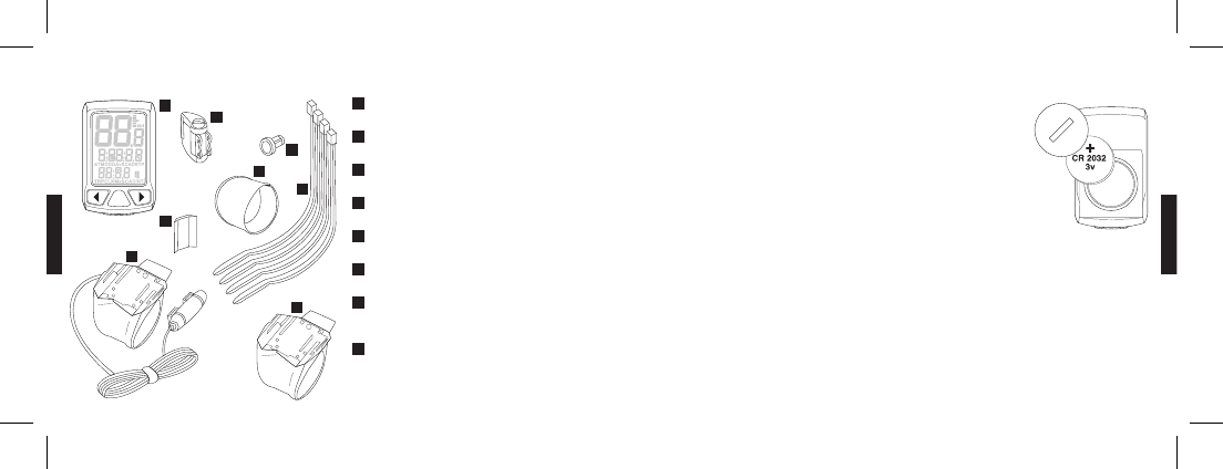
SpeedZone Cycle Computers are powered by a CR2032 3v Lithium Battery. Under normal
conditions, battery life should be approximately one year.
INSTALLING OR REPLACING THE COMPUTER BATTERY
1. Using a coin or flathead screwdriver, turn the battery door counter clockwise and
remove the battery compartment cover.
2. Carefully remove the old battery. Take care not to damage the O-ring seal.
3. Place a new battery in the battery compartment with the positive (+) side facing the
battery compartment door. CAUTION: Do not bend the battery contact.
4. Replace the battery compartment cover and tighten clockwise with a coin or flathead
screwdriver.
NOTE: If the O-ring is damaged, replace it before installing the battery compartment cover.
CAUTION: Extreme care should be taken to ensure the unit is fully water-resistant. Failure to properly replace the
battery and correctly seal the battery compartment cover may cause the unit to be damaged and void the
warranty.
ALWAYS: Check the batteries if you are experiencing problems with your computer. Most problems with the operation
of this unit are the result of dead or dying batteries.
COMPONENTS OF THE CYCLOCOMPUTER
FACE OF COMPUTER
ZIP- TIES
BRACKET SLEEVE
WHEEL MAGNET
WIRED SPEED BRACKET (SPORT ONLY)
WIRELESS SPEED BRACKET (SPORT WIRELESS ONLY)
WIRELESS FORK TRANSMITTER
(SPORT WIRELESS ONLY)
WIRELESS FORK TRANSMITTER
MOUNTING PAD (SPORT WIRELESS ONLY)
1
4
2
3
8
7
5
6
1
2
3
4
5
6
7
8
REPLACING THE BATTERY

6
english
7
english
INSTALLING THE STEERER TUBE MOUNT INSTALLING THE HANDLE BAR BRACKET
SpeedZone computers give you the option of mounting the computer in-line with your stem.
This option is ideal for aero bars or to keep a visually balanced look to the handlebars.
1. Remove the bicycles’ steering column stem cap.
NOTE: It is not necessary to loosen the stem.
2. Install the Specialized steering column mount ring, with computer mount ON TOP of the
stem or any spacers present so that it partially overlaps the top of the steerer tube.
NOTE: It is important the stem mount ring be the last item mounted before the steering
column stem cap.
3. Rotate and align the steering column mount ring, with computer mount so it is parallel to
your stem extension.
4. Reinstall the bicycles’ steering column stem cap and tighten to manufacturer’s
specification.
IMPORTANT: The Specialized steerer tube mount may not work properly with some high-rise
stems. In the case of high-rise stems, the steerer tube (and spacers) must extend
beyond the stem enough to allow proper clearance of mounting bracket.
On bikes with high-rise stems or threaded headsets, SpeedZone computers give you the
option of mounting the computer on your handle bars..
1. Remove the computer mount from the steering column mount using a 3mm hex wrench.
(confirm with Ian on hex wrench size!)
2. Install the molded rubber shim for 31.8mm handlebars and thread the included two (2)
zip-ties through the handlebar mount and molded rubber shim.
3. Loosely install the mount and shim assembly (for 25.4mm and 26.0mm handlebars, use
the additional flat rubber spacer underneath the molded rubber shim) and install to the
preferred handlebar location.
4. Rotate the zip-tie heads so they nest under the front of the mount, adjust the position as
necessary and tighten the zip-ties.
5. Trim the excess zip-ties for a finished appearance.
need illustration
of removing
steerer cap
need illustration
of of installing the
stem mount on
steerer tube
need illustration of
securing steerer
tube cap & installed
unit
need illustration
for #1
(Image: exploded
view with all shims
& zip-ties threaded)
(image: installed
unit)
8
english
9
english
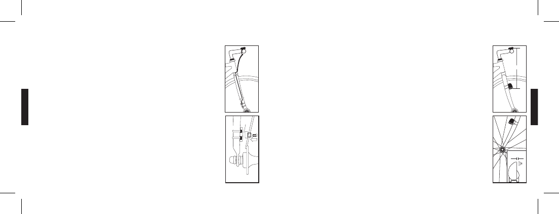
WIRED SPEED SENSOR INSTALLATION
The SpeedZone Sport is best installed starting with the fork sensor unit and then working up toward
the handlebar or stem bracket.
1. Pass the two cable ties through the sensor mounting holes and loosely mount the fork sensor
body to the left or right fork blade (do not fully tighten the cable ties at this point).
2. Loosely install the sensor magnet to one of the spokes of the front wheel. Adjust the position of
the magnet and sensor together so that the magnet is aligned with the line on the bottom edge
of the sensor and 1-2 mm separates the two parts and tighten both parts in place.
3. Route the wire up the fork securing it in place with electrical tape.
CAUTION: Do not use cable ties to secure the wire as they can break the wire. Make sure to leave
enough slack in the wire to allow for the motion of the bike steering system and the
suspension fork if you have one.
4. Wrap any excess wire around the front brake cable housing. Use electrical tape to secure the
cable in place if it is necessary. When you are done you should have just enough wire left for the
handle bar or stem bracket to reach the mounting point.
INSTALLING THE SPEED SENSOR INSTALLING THE SPEED SENSOR
WIRELESS SPEED SENSOR INSTALLATION
(SPORT WIRELESS ONLY)
1. Pass the two cable ties through the sensor mounting holes and loosely mount to the left fork
leg using the rubber sensor mounting pad (do not fully tighten the cable ties at this point). The
sensor should be mounted as close to the top of the fork as possible with the cap of the battery
door toward the ground. Make sure that the distance between the sensor and the handlebars is
no more than 24 in. (610mm).
2. Loosely install the sensor magnet to one of the spokes of the front wheel. Adjust the position
of the magnet and sensor together so that the magnet is aligned with the line on the bottom
edge of the sensor and 1-2 mm separates the two parts and tighten both parts in place. DO NOT
over-tighten the magnet screw.
10
english
11
english
PROGRAMMING THE CYCLOCOMPUTER PROGRAMMING THE CYCLOCOMPUTER
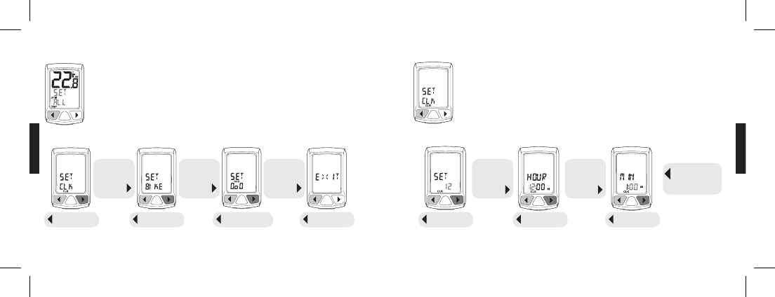
PRIMARY SETTING SEQUENCE
From any main mode screen PRESS & HOLD the PREV key to enter the primary setting sequence. Scroll
through settings by PRESSING the NEXT key. Accept a setting to adjust by PRESSING the PREV key.
NOTE: PRESS & HOLD the PREV key in any primary or secondary set screen to EXIT setting sequence and escape
to main operating mode.
SETTING TIME
From the set clock screen PRESS the PREV key to SET TIME. Adjust the value being programmed by
PRESSING the NEXT key. Set the displayed value by PRESSING the PREV key.
NOTE: PRESS & HOLD the NEXT key while adjusting a value to fast advance in a continuous loop.
continue to
PRESS & HOLD
PRESS
NEXT
scroll through
SETTING
MODES
SET CLOCK
PRESS PREV
SET BIKE
PRESS PREV
SET ODOMETER
PRESS PREV
PRESS
NEXT
adjust value
EXIT
PRESS PREV
12/24 HOUR
PRESS PREV
SET HOUR
PRESS PREV
SET MINUTES
PRESS PREV
PRESS PREV
to return to
SET MENU
PRESS
NEXT
scroll through
SETTING
MODES
PRESS
NEXT
scroll through
SETTING
MODES
PRESS
NEXT
adjust value
12
english
13
english
PROGRAMMING THE CYCLOCOMPUTER
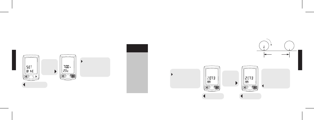
SETTING WHEEL SIZE WITH PRE-PROGRAMMED VALUES
For easy setup, SpeedZone computers come with 14 pre-programmed wheel/tire sizes. Simply select the size of your tire
as you scroll through the list in the programming sequence and you are done.
From the SET BIKE screen PRESS the PREV key to enter the setting sequence. Scroll through the pre-programmed values
by PRESSING the NEXT key. Set the displayed value by PRESSING the PREV key.
PROGRAMMING THE CYCLOCOMPUTER
MANUALLY SETTING WHEEL SIZE
If your wheel/tire size is not one of the pre-programmed sizes, or if you desire absolute accuracy, you may enter an exact
wheel circumference into the system.
1. On a flat open surface make a mark on your tire and the floor exactly where
they meet.
2. Roll your bike forward one full revolution of the wheel and mark the point on
the floor where the revolution is complete.
3. Measure the distance from the first mark to the second in millimeters and enter
the resulting number into your computer using the following steps:
26 X 1.0
26 X 1.25
26 X 1.5
26 X 1.9
26 X 1.95
26 X 2.0
26 X 2.1
26 X 2.2
650 X 20C
700 X 20C
700 X 23C
700 X 26C
700 X 32C
700 X 38C
NOTE: PRESS & HOLD the PREV key in any primary or secondary SET screen to EXIT setting sequence and resume
main operating mode.
Pre-programmed
wheel sizes
PRESS
NEXT
scroll through
WHEEL
SIZES
continue
PRESSING NEXT
to scroll through
pre-programmed sizes
and MANUALLY SET
WHEEL SIZE
SET WHEEL SIZE
PRESS PREV
continue
PRESSING NEXT
to scroll through
pre-programmed sizes
and MANUALLY SET
WHEEL SIZE
continue
SETTING SEQUENCE
through all fields.
Return to MAIN
SET PROGRAM:
PRESS PREV
PRESS
NEXT
adjust value
SET VALUE
PRESS PREV
SET VALUE
PRESS PREV
14
english
15
english
PROGRAMMING THE CYCLOCOMPUTER RESET THE CYCLOCOMPUTERPROGRAMMING THE CYCLOCOMPUTER
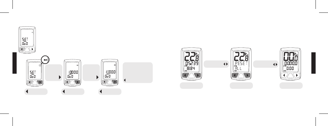
SETTING ODOMETER
SpeedZone Cycle Computers allow you to manually adjust the Odometer. From the SET ODO screen
PRESS the PREV key to enter the setting sequence.
NOTE: PRESS & HOLD the NEXT key while adjusting a value to fast advance in a continuous loop.
NOTE: PRESS & HOLD the PREV key in any primary or secondary set screen to escape to main mode screens.
To reset the computer, from any operating mode screen PRESS & HOLD the PREV and NEXT keys simultaneously to reset
the cyclocomputer.
PRESS
NEXT
adjust value
SET MPH/KPH
PRESS PREV
SET VALUE
PRESS PREV
SET VALUE
PRESS PREV
continue
SETTING SEQUENCE
through all fields.
Return to MAIN
SET PROGRAM:
PRESS PREV
PRESS & HOLD
.5 SEC PRESS & HOLD
2 SEC
MAIN MODE
SCREEN
RESET
SEQUENCE
SCREEN AFTER
REST
PRESS
NEXT
adjust value

16
english
17
english
SPECIFICATIONS AND RANGES
TIME OF DAY
• 24 hours with one minute resolution
• Functional in either 12 or 24 hour formats
• Default value = 12:00.00 PM, January 1, 2006
ODOMETER
• 99999 miles or kilometers
• 1 mile or 1 kilometer resolution
WHEEL SIZE
• 14 pre-programmed wheel sizes
• Wheel circumference measured in millimeters
SPEED
• 0-99.9 MPH or KPH
• 0.1 MPH or KPH resolution
OPERATING TEMPERATURE
• 40°F to 104°F (4°C to 40°C)
TROUBLESHOOTING
DISPLAY IS BLANK: Change the battery or reset the
computer (see page 15).
DISPLAY SHOWS PARTIAL DIGITS: Reset the computer.
SPEED/DISTANCE NOT RECORDING: Check sensor/mag-
net alignment. Make sure that the sensor is no more than
1/16" (2mm) from the magnet.
ENTIRE SCREEN IS DARK: Did you have the bike parked in
the hot direct sun when it was parked? If so, move the bike
to the shade. The data will be OK.
COMPUTER MOVES ON HANDLEBAR: Tighten tie straps or
add sizing straps to improve fit on handlebar.
IMPORTANT
• Pay attention to traffic and road conditions at all times.
Your first obligation is to be attentive and to ride
safely.
• Keep your computer in good shape and use it safely.
• Do not expose the computer to direct sunlight except
when you are riding.
• Do not disassemble the computer.
• Make sure the magnet and the transmitter are well
aligned and check them regularly
• Keep the computer and all of its components tightly
attached and check them regularly. If any of the
components come loose, it could become tangled in
your spokes and cause and accident.
• See your authorized Specialized dealer if you have any
trouble installing or maintaining your computer.
• Clean the unit with a mild detergent and a soft dry
cloth. Never use any kind of solvent or alcohol.
• The SpeedZone Sport Cyclocomputer is intended for
use on bicycles only and should not be used on any
motorized vehicle.

18
english
WARRANTY INFORMATION
Specialized cycling computers are guaranteed to be free from defects in materials and/or workmanship (excluding
battery) for a period of two years from the date of purchase. Specialized will, at its option, repair or replace your defective
computer.
To recieve warranty service send the unit, a copy of the sales receipt and a brief description of the problem to:
Specialized Bicycle Components Inc.
15130 Concord Circle
Morgan Hill, CA 95037
ATTN: Product Services/Computer Warranty
SpeedZone is a registered trademark of Specialized Bicycle Components Inc.
© 2007 Specialized Bicycle Components Inc.
WWW.SPECIALIZED.COM
