Gen4 Size 8 Product Manual V3_3 (RELEASED) V3 3
User Manual:
Open the PDF directly: View PDF ![]() .
.
Page Count: 130 [warning: Documents this large are best viewed by clicking the View PDF Link!]
- Document no:
- 177/52901
- Rev. 3.3
- 1 Chapter 1: Introduction
- 2 Chapter 2: About the Gen4 Size 8
- 3 Chapter 3: Installation
- 4 Chapter 4: Specification
- 5 Chapter 5: System Design
- 6 Chapter 6: Configuration
- Introduction
- DVT configuration tool
- CANopen
- Configuration process overview
- Motor characterization
- I/O configuration
- Vehicle performance configuration
- Safety Interlocks
- Torque mode/speed mode
- Throttle
- Driveability Features
- Acceleration and braking
- Footbrake
- Steering inputs – twin driving motor systems
- Driveability profiles
- Preventing Wheel Lock Scenarios
- Controlled roll-off
- Hill hold
- Inching
- Belly Switch
- Drivability select switches
- Economy
- Pump configuration
- Power steer configuration
- Vehicle features and functions
- 7 Chapter 7: Monitoring Gen4 Size 8

Gen4 Size 8
Applications
Reference
Manual
Document no:
177/52901
Rev. 3.3

Sevcon Ltd
Kingsway South
Gateshead, NE11 0QA
England
Tel: +44 (0)191 497 9000
Fax: +44 (0)191 482 4223
sales.uk@sevcon.com
Sevcon, Inc.
155 Northboro Road
Southborough, MA 01772
USA
Tel: (508) 281 5500
Fax: (508) 281 5341
sales.us@sevcon.com
Sevcon SAS
Parc d’Activité du Vert Galant
Rue Saint Simon
St Ouen l’Aumône
95041 Cergy Pontoise Cedex
France
Tel: +33 (0)1 34 30 35 00
Fax: +33 (0)1 34 21 77 02
sales.fr@sevcon.com
Sevcon Japan K.K.
Kansai Office
51-26 Ohyabu Hikone
Shiga
Japan
522-0053
Tel: +81 (0) 7 49465766
jp.info@sevcon.com
Sevcon Asia Ltd
Room No.202 Dong-Ah Heights
Bldg
449-1 Sang-Dong Wonmi-Gu
Bucheon City Gyeounggi-Do
420-816, Korea
Tel: +82 32 215 5070
sales.kr@sevcon.com
Sevcon Germany
Hintere Str.32
73266
Bissingen an der Teck
Germany
Tel: +49 (0)170 9980294
de.info@sevcon.com
www.sevcon.com
ii
CONTENTS
DOCUMENT NO: ................................................................................................................................... 1
177/52901 ............................................................................................................................................ 1
REV. 3.3 ................................................................................................................................................ 1
CHAPTER 1: INTRODUCTION ............................................................................................................. 1-1
............................................................................................................................................................. 1-1
ABOUT GEN4 SIZE 8 DOCUMENTATION ........................................................................................................ 1-2
This version of the manual .............................................................................................................. 1-2
Copyright ......................................................................................................................................... 1-2
Scope of this manual ....................................................................................................................... 1-2
Related documents ......................................................................................................................... 1-2
Drawings and units ......................................................................................................................... 1-2
Warnings, cautions and notes......................................................................................................... 1-3
PRODUCT IDENTIFICATION LABEL ................................................................................................................. 1-4
TECHNICAL SUPPORT ................................................................................................................................. 1-4
PRODUCT WARRANTY ............................................................................................................................... 1-4
CHAPTER 2: ABOUT THE GEN4 SIZE 8 ................................................................................................ 2-1
INTRODUCTION ........................................................................................................................................ 2-2
STANDARD FEATURES AND CAPABILITIES ........................................................................................................ 2-2
Intended use of the Gen4 Size 8 ...................................................................................................... 2-2
Available accessories....................................................................................................................... 2-3
OVERVIEW OF A VEHICLE DRIVE SYSTEM ......................................................................................................... 2-4
PRINCIPLES OF OPERATION .......................................................................................................................... 2-5
Functional description ..................................................................................................................... 2-5
Gen4 Size 8 electrical block diagram ............................................................................................... 2-5
Interfaces ........................................................................................................................................ 2-8
Master-slave operation ................................................................................................................... 2-8
Torque mode ................................................................................................................................... 2-9
Speed mode ..................................................................................................................................... 2-9
SAFETY AND PROTECTIVE FUNCTIONS .......................................................................................................... 2-10
General .......................................................................................................................................... 2-10
On-Highway Vehicles .................................................................................................................... 2-12
Doc No: 177/52701 iii
Rev: 3.3
Fault detection and handling ........................................................................................................ 2-14
CHAPTER 3: INSTALLATION ............................................................................................................... 3-1
MOUNTING GEN4 SIZE 8 ........................................................................................................................... 3-2
Location ........................................................................................................................................... 3-2
Protection from chemical contamination ....................................................................................... 3-2
Orientation ...................................................................................................................................... 3-2
Clearance for LED access ................................................................................................................. 3-2
Mounting hole pattern: ................................................................................................................... 3-3
COOLING REQUIREMENTS ........................................................................................................................... 3-5
Water Glycol Pressure Drop. ........................................................................................................... 3-6
EMC GUIDELINES ..................................................................................................................................... 3-7
General measures ........................................................................................................................... 3-7
Measures required for specific signals ............................................................................................ 3-7
Additional measures ....................................................................................................................... 3-9
Problems to avoid ........................................................................................................................... 3-9
CONNECTING POWER CABLES .................................................................................................................... 3-10
Battery and motor connections..................................................................................................... 3-10
Screened cables and metal screened cable glands ....................................................................... 3-10
Chassis conection to heatsink. ...................................................................................................... 3-11
Fitting the Terminal Cover ............................................................................................................. 3-11
Cable sizes ..................................................................................................................................... 3-11
Fuse rating and selection .............................................................................................................. 3-12
SIGNAL WIRING ...................................................................................................................................... 3-13
Signal wire sizes ............................................................................................................................ 3-13
CANbus termination ...................................................................................................................... 3-13
SIGNAL CONNECTIONS ............................................................................................................................. 3-14
CHAPTER 4: SPECIFICATION ............................................................................................................... 4-1
ELECTRICAL .............................................................................................................................................. 4-2
Input voltage – control supply......................................................................................................... 4-2
Input voltage – traction supply ....................................................................................................... 4-2
Output protection ........................................................................................................................... 4-2
Output ratings ................................................................................................................................. 4-3
CAN interface .................................................................................................................................. 4-4
Control inputs and outputs ............................................................................................................. 4-4
iv
Isolation .......................................................................................................................................... 4-6
EMC ................................................................................................................................................. 4-7
Regulatory compliance ................................................................................................................... 4-8
X and Y Capacitance ........................................................................................................................ 4-8
MECHANICAL ........................................................................................................................................... 4-9
Operating environment ................................................................................................................... 4-9
Shock and vibration ....................................................................................................................... 4-10
Weight........................................................................................................................................... 4-10
Dimensions Gen4 Size 8 ................................................................................................................ 4-11
Liquid Cooled Model: ..................................................................................................................... 4-11
Fan Cooled Model: ........................................................................................................................ 4-12
CHAPTER 5: SYSTEM DESIGN ............................................................................................................. 5-1
SIZING A MOTOR ....................................................................................................................................... 5-2
Information required about the application ................................................................................... 5-2
Motor maximum speed ................................................................................................................... 5-2
Active Short Circuit Protection ........................................................................................................ 5-2
Torque required between zero and base speed .............................................................................. 5-3
Torque required at maximum speed ............................................................................................... 5-3
Continuous power rating................................................................................................................. 5-4
Peak power rating ........................................................................................................................... 5-4
SELECTING THE GEN4 SIZE 8 MODEL ............................................................................................................. 5-5
Current and power ratings considerations ...................................................................................... 5-5
Power output restrictions at motor and drive operating temperature limits ................................. 5-5
Circuit configuration ....................................................................................................................... 5-6
Single traction wiring diagram ........................................................................................................ 5-7
TWIN MOTOR SYSTEMS .............................................................................................................................. 5-8
AUXILIARY COMPONENTS ........................................................................................................................... 5-8
Main Contactor and Precharge circuit ............................................................................................ 5-8
Contactors controlled from Gen4 Size 8 ........................................................................................ 5-10
35 Way AMPSeal Connector Kit .................................................................................................... 5-10
Emergency stop switch ................................................................................................................. 5-10
Key switch fuse F2 ......................................................................................................................... 5-10
Motor speed sensor (encoder) ...................................................................................................... 5-10
Motor commutation sensor .......................................................................................................... 5-11
Doc No: 177/52701 v
Rev: 3.3
INITIAL POWER UP SEQUENCE .................................................................................................................... 5-15
Checks prior to power up .............................................................................................................. 5-15
Checks after power is applied ....................................................................................................... 5-15
DISCHARGE SEQUENCE AFTER POWER DOWN ................................................................................................ 5-16
Controller discharge profiles ......................................................................................................... 5-16
CHAPTER 6: CONFIGURATION ........................................................................................................... 6-1
INTRODUCTION ........................................................................................................................................ 6-2
DVT CONFIGURATION TOOL ........................................................................................................................ 6-2
DVT functionality............................................................................................................................. 6-2
Saving, duplicating and restoring a node’s configuration............................................................... 6-2
Data Logging. .................................................................................................................................. 6-3
CANOPEN ............................................................................................................................................... 6-3
CANopen protocol ........................................................................................................................... 6-3
Object Dictionary ............................................................................................................................ 6-4
Communication objects ................................................................................................................... 6-4
Network Configuration ................................................................................................................... 6-5
CONFIGURATION PROCESS OVERVIEW ........................................................................................................... 6-7
Access authorization ....................................................................................................................... 6-7
How NMT state affects access to parameters ................................................................................ 6-7
MOTOR CHARACTERIZATION ....................................................................................................................... 6-8
Determining induction motor parameters ...................................................................................... 6-8
Self characterization ....................................................................................................................... 6-9
Determining PMAC motor parameters ........................................................................................... 6-9
I/O CONFIGURATION ............................................................................................................................... 6-10
Manual object mapping ................................................................................................................ 6-11
Encoder ......................................................................................................................................... 6-14
Digital inputs ................................................................................................................................. 6-14
Analog inputs ................................................................................................................................ 6-14
Analog (contactor) outputs ........................................................................................................... 6-16
VEHICLE PERFORMANCE CONFIGURATION .................................................................................................... 6-18
Safety Interlocks ............................................................................................................................ 6-18
Torque mode/speed mode ............................................................................................................ 6-19
Throttle ......................................................................................................................................... 6-19
Driveability Features ..................................................................................................................... 6-23
vi
Acceleration and braking .............................................................................................................. 6-24
Footbrake ...................................................................................................................................... 6-24
Steering inputs – twin driving motor systems ............................................................................... 6-24
Driveability profiles ....................................................................................................................... 6-26
Preventing Wheel Lock Scenarios .................................................................................................. 6-28
Controlled roll-off .......................................................................................................................... 6-29
Hill hold ......................................................................................................................................... 6-30
Inching ........................................................................................................................................... 6-30
Belly Switch ................................................................................................................................... 6-30
Drivability select switches ............................................................................................................. 6-31
Economy ........................................................................................................................................ 6-31
Pump configuration ...................................................................................................................... 6-31
Power steer configuration ............................................................................................................. 6-33
VEHICLE FEATURES AND FUNCTIONS............................................................................................................ 6-34
Contactors ..................................................................................................................................... 6-34
Line contactor ............................................................................................................................... 6-34
Electro-mechanical brake .............................................................................................................. 6-34
External LED .................................................................................................................................. 6-34
Alarm buzzer ................................................................................................................................. 6-34
Brake Lights ................................................................................................................................... 6-35
Horn .............................................................................................................................................. 6-35
Service indication .......................................................................................................................... 6-35
Traction motor cooling fan ........................................................................................................... 6-36
Controller heatsink fan .................................................................................................................. 6-36
Controller external heatsink /motor cooling fan ........................................................................... 6-36
Motor over-temperature protection ............................................................................................. 6-36
Motor over-speed protection ........................................................................................................ 6-37
Battery protection ......................................................................................................................... 6-37
Displays ......................................................................................................................................... 6-38
CHAPTER 7: MONITORING GEN4 SIZE 8 ................................................................................................ 1
READING STATUS VARIABLES .......................................................................................................................... 2
Motor measurements ........................................................................................................................ 2
Heatsink temperature ........................................................................................................................ 2
Identification and version .................................................................................................................. 2
Doc No: 177/52701 vii
Rev: 3.3
Battery monitoring ............................................................................................................................. 2
Hours counters ................................................................................................................................... 3
LOGGING ................................................................................................................................................... 3
FIFO event logs ................................................................................................................................... 3
Event counters.................................................................................................................................... 4
Operational monitoring ..................................................................................................................... 4
CANOPEN ABORT CODE ................................................................................................................................ 4
FAULTS AND WARNINGS ................................................................................................................................ 6
Introduction ....................................................................................................................................... 6
Fault identification ............................................................................................................................. 6
Fault list ............................................................................................................................................ 11
UPGRADING THE CONTROLLER SOFTWARE ....................................................................................................... 12

CHAPTER 1:
INTRODUCTION

1-2
About Gen4 Size 8 Documentation
This version of the manual
This version of the Gen4 Size 8 manual replaces all previous versions. Sevcon has made every
effort to ensure this document is complete and accurate at the time of printing. In accordance
with our policy of continuing product improvement, all data in this document is subject to change
or correction without prior notice.
Copyright
This manual is copyrighted 2011 by Sevcon. All rights are reserved. This manual may not be
copied in whole or in part, nor transferred to any other media or language, without the express
written permission of Sevcon.
Scope of this manual
The Application Reference Manual provides important information on configuring lift and
traction drive systems using Gen4 Size 8 controllers as well as details on sizing and selecting
system components, options and accessories.
The manual also presents important information about the Gen4 Size 8 product range.
Related documents
The following documents are available from Sevcon:
The Object Dictionary providing important information about CANopen communication
with Gen4 Size 8.
Device Configuration Files (DCF) and Electronic Data Sheets (EDS) for each Gen4 Size 8
model and revision.
Drawings and units
Orthographic illustrations in this manual are drawn in Third Angle Projection. SI units are used
throughout this manual.
Introduction
Doc No: 177/52701 1-3
Rev: 3.3
Warnings, cautions and notes
Special attention must be paid to the information presented in Warnings, Cautions and Notes
when they appear in this manual. Examples of the style and purpose of each are shown below:
A WARNING is an instruction that draws attention to the risk of injury or death and tells you how to
avoid the problem.
A CAUTION is an instruction that draws attention to the risk of damage to the product, process or
surroundings.
A NOTE indicates important information that helps you make better use of your Sevcon product.
1-4
Product Identification Label
If you have a customized product your unique identifier will appear at the end of the Type
number. When discussing technical issues with Sevcon always have your product’s Type number,
Part number and Serial number available. Figure 1 shows a typical product identification label.
Figure 1: Product Identification Label
Technical Support
For technical queries and application engineering support on this or any other Sevcon product
please contact your nearest Sevcon sales office listed on the inside front cover of this manual.
Alternatively you can submit enquiries and find the details of the nearest support centre through
the Sevcon website, www.sevcon.com.
Product Warranty
Please refer to the terms and conditions of sale or contract under which the Gen4 Size 8 was
purchased for full details of the applicable warranty.

CHAPTER 2: ABOUT THE
GEN4 SIZE 8

2-2
Introduction
Sevcon Gen4 Size 8 controllers are designed to control 3-phase AC induction motors and
Permanent Magnet AC (PMAC) motors in battery powered traction and pump applications. A
range of models is available to suit a wide number of applications and cooling regimes.
The controller adapts its output current to suit the loading conditions and the ambient in which
it is operating (temporarily shutting down if necessary). It will also protect itself if incorrectly
wired.
Signal wiring and power connections have been designed to be as simple and straight forward as
possible. Analog and digital signal inputs and outputs are provided for switches, sensors,
contactors, hydraulic valves and CAN communications. These electrical signals can be mapped to
Gen4 Size 8’s software functions to suit a wide range of traction and pump applications.
Given Gen4 Size 8’s mapping versatility it is important to ensure you map your application signals
to the correct software functions (see ‘Manual object mapping’ on page 6-11). A common
configuration is supplied by default which may suit your needs or act as a starting point for further
configuration.
Configuration and control of Gen4 Size 8 is fully customizable using Sevcon’s Calibrator handset
or DVT, an intuitive Windows based configuration software tool.
A single green LED is provided to give a visual indication of the state of the controller. This signal
can be replicated on a dashboard mounted light for example.
Standard features and capabilities
Intended use of the Gen4 Size 8
The Gen4 Size 8 motor controller can be used in any of these main applications for traction
control:
Automobiles
Vans
Light trucks
Buses
Airport ground support (AGS), including tow tractors
Utility vehicles
Burden carriers
Marine
About the Gen4 Size 8
Doc No: 177/52701 2-3
Rev: 3.3
Available accessories
The following accessories are available from Sevcon
Loose equipment kit (connectors and pins) for Gen4 Size 8
DCDC converters
SmartView™ display
Hourmeters
Contactors
Fuses
DVT - PC based configuration tool
SCWiz – PC based motor characterisation tool
2-4
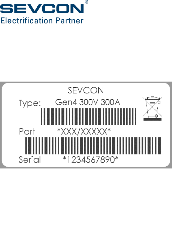
Overview of a vehicle drive system
The main components (excluding control inputs such as throttle and seat switch) are shown in
Figure 2. In this example there are two traction motors. Communication between the controllers
is achieved using the CANopen protocol. This protocol also allows Gen4 Size 8 to communicate
with Sevcon displays as well as other non-Sevcon, CANopen compliant devices.
Figure 2: Vehicle System Components
A fuse, pre-charge circuit and line contactor must be fitted between the traction battery and the
controller power circuits.
Fuse and
switch
Traction
battery
Isolated
DCDC
Vehicle
Control Unit
(VCU)
Traction motor
Traction motor
Traction
inverter
Traction
inverter
= LV control wiring
= LV isolated CAN wiring
= HV bus wiring
Traction
battery
LV battery
(12 – 24V)
Vehicle
Control Unit
(VCU)
Traction motor
Traction motor
Traction
inverter
Traction
inverter
Fuse and
switch
Or

About the Gen4 Size 8
Doc No: 177/52701 2-5
Rev: 3.3
Principles of operation
Functional description
The main function of Gen4 Size 8 is to control the power to 3-phase squirrel-cage AC induction
or PMAC motors in electric vehicles. Four-quadrant control of motor torque and speed (driving
and braking torque in the forward and reverse directions) is allowed without the need for
directional contactors. Regenerative braking is used to recover kinetic energy which is converted
into electrical energy for storage in the battery.
In a traction application control commands are made by the driver using a combination of digital
controls (direction, foot switch, seat switch, etc.) and analog controls (throttle and foot brake).
The controller provides all the functions necessary to validate the driver’s commands and to
profile the demand for speed and torque according to stored parameters.
Throttle inputs can be configured as speed or torque demands with throttle-dependent speed
limits: in either case, a torque demand is continually calculated to take account of pre-set limits
on the level and rate-of-change of torque. The torque demand is used to calculate current
demands; that is, the controller calculates what currents will be required within the motor to
generate the required torque.
There are two distinct components of the current, known as the d-q axis currents, which control
current flow in the motor. The d-axis current is responsible for producing magnetic flux, but does
not by itself produce torque. The q-axis current represents the torque-producing current.
When a vehicle is ready to drive, but no torque is being demanded by the driver, the d-axis or
magnetizing current will be present in the motor so that the vehicle will respond immediately to
a torque demand. To save energy the magnetizing current is removed if the vehicle is stationary
and no torque has been demanded after a set period.
Measured phase currents and current demands id and iq, the d-q axis currents, are used as part
of a closed-loop control system to calculate the necessary voltage demands for each phase of the
motor. Voltage demands are then turned into PWM demands for each phase using the Space
Vector Modulation (SVM) technique. SVM ensures optimum use of the power semiconductors.
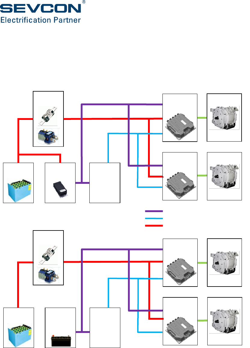
Gen4 Size 8 electrical block diagram
The electrical circuit blocks present in Gen4 Size 8 are shown in Figure 3 and have the following
functions:-
Inverter power stage – this converts the DC battery supply into AC to power the motor. See the
following section for more details.
Gate drives – the low power gate control signal from the control logic is isolated and buffered by
these circuits. Output short circuits are also detected by these circuits.
Current and voltage measurement – these circuits provide an isolated voltage and current
measurement for the control logic. Over-current and over-voltage conditions are also detected.
Control power supplies – these convert a 24V nominal supply into the voltage required for the
control logic

2-6
Control logic – software runs on microprocessor and DSP circuits with input and output circuits
for analogue and digital inputs, the encoder, CAN bus and analogue outputs.
Isolation fault detector – An external Isolation Fault Detector must be fitted in high voltage
systems. This circuit must detect if the high voltage battery is shorted to the logic circuits.
The high voltage power circuits are fully isolated from the logic control and CAN circuits. All of
the required power supplies and control signals for the high voltage system are isolated
magnetically or optically from the low voltage system .
All the control inputs and outputs such as the analogue inputs, digital inputs and motor encoder
are referenced to the 24V logic circuit ground. The Can bus is isolated from the control circuit
ground with an isolation resistance of 1 MΩ . A separate CAN ground is made available on the
user light wiring connector.
Do not connect the high voltage traction circuit to the 24V logic circuits directly. If you do this the
isolation barrier will be bypassed. This could cause high voltages to be present on circuits which
do not have enough protection against accidental touch. Protection of logic circuits against
accidental shorts to the high voltage battery relies on this isolation barrier. If a wiring fault was
present logic circuits could be damaged.
About the Gen4 Size 8
Doc No: 177/52701 2-7
Rev: 3.3
Figure 3: Motor Controller Electrical Block Diagram
Power conversion section
The power conversion section of Gen4 Size 8 employs a 6-switch IGBT bridge operating at an
effective frequency of either 16 kHz or 24 kHz (the PWM frequency is set using 5830h). Excellent
electrical and thermal efficiency is achieved by:
Minimization of thermal resistances.
Use of the latest IGBT technology
Internal thermal protection (if temperatures are excessive, output torque is reduced).
Overcurrent protection using device characteristics.
Internal measurement of output current.
Overvoltage trip in the event of regenerative braking raising battery voltage to unsafe
levels.
300V
Current and
voltage
measurement
Gate drives
and
protection
circuits
Control logic and processor
Control power
supplies
Inverter power stage
I/O
CAN bus
24V in
24V in
Encoder
Isolation fault
detection (Alpha
controller only)
Isolation

2-8
Dual traction motor
In the case of dual traction motors, there is additional processing of the associated steering signal
(from a potentiometer or switches) in order to generate separate torque demands for the left
and right motors of the vehicle. This allows the two motors to be operated at different speeds,
which greatly assists in turning the vehicle and prevents wheel scrub. After the torque demands
have been generated, the operation of each motor control system is as described in the case of
a single traction motor.
Pump motors
Pump motor control is similar to traction motor control, although motion is requested using a
different combination of switches.
Interfaces
In addition to its motor control functions, Gen4 Size 8 offers many other functions designed to
interface with electric vehicles. A variety of digital and analog input sources are supported, as
listed in ‘Signal connections’ on page 3-14.
Voltage and current control of up to three contactors or proportional valves is provided by Gen4
Size 8, and includes built-in freewheeling diodes for spike suppression. All I/O on the Gen4 Size 8
controller is protected against short-circuit to the control logic positive and negative supply.
There is an exception to the protection for the Pusled Digital Output on the initial production of
Gen4 Size 8 Beta controllers. Initial production Beta controllers do not have protection for short-
circuit of the Pulsed Digital Output to the control logic positive supply. Contact Sevcon for further
details of the status of the protection.
Connectivity and interoperability with other system devices (for example another Gen4 Size 8
controller) using a CANbus and the CANopen protocol is provided. In addition to in-service
operation, the CANopen protocol allows the controller to be commissioned using the Calibrator
handset or Sevcon’s DVT tool. In addition Sevcon’s SCWiz PC based tool provides the function to
self-characterise most induction motors and hence simplify the process of putting a new motor
into service.
For simple visual diagnosis of system faults and to monitor system status, a green LED is provided
on the body of the controller. It is continuously lit when there is no fault but flashes a different
number of times, in a repeated pattern, when there is a fault. The number of flashes indicates
the type of fault (see Fault and Warnings in the Appendix).
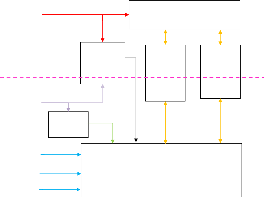
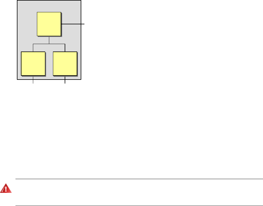
Master-slave operation
The Gen4 Size 8 controller contains both master and slave functions as shown in Figure 4. They
operate as follows:
Slave function: implements the CANopen Generic I/O Profile (DS401) and the Drives and
Motion Control Profile (DSP402).
Master function: implements vehicle functionality (traction and pump control) and
CANopen network management.
About the Gen4 Size 8
Doc No: 177/52701 2-9
Rev: 3.3
Figure 4: Single Controller
Torque mode
In this mode Gen4 Size 8 maintains the motor torque output at a constant value for a given
throttle position. This is similar to DC motors (in particular, series wound DC motors) and provides
a driving experience like a car. To prevent excessive speed when the load torque is low, for
example when driving down hill, a maximum vehicle speed can be set.
Speed mode
Speed mode (or speed control) is not recommended for on-highway vehicles as it can cause the
traction motor/wheel to remain locked or brake severely if the wheel is momentarily locked due to
loss of traction on a slippery surface and/or mechanical braking.
In this mode Gen4 Size 8 maintains the motor at a constant speed for a given throttle position as
long as sufficient torque is available. Speed mode differs from torque mode in that the torque
value applied to the motor is calculated by the controller based on the operator’s requested
speed (determined by throttle position) and the vehicle’s actual speed. This mode is useful where
accurate speed control is required irrespective of the motor torque.
Controller
to motors, switches,
pedals etc
CANopen
I/O
slave motor
slave
master
function
2-10
Safety and protective functions
General
Electric vehicles can be dangerous. All testing, fault-finding and adjustment should be carried out by
competent personnel. The drive wheels should be off the floor and free to rotate during the
following procedures. The vehicle manufacturer's manual should be consulted before any operation
is attempted.
The battery must be disconnected before replacing the controller. After the battery has been
disconnected wait for the internal capacitors to discharge to less than 60V before handling the
controller or working near exposed terminals.
Refer to Hazardous voltages may remain on the controller internally and on exposed power
terminals after the main battery power connections and keyswitch power supplies have been
removed if the controller is connected to a rotating permanent magnet motor.
Controller discharge profiles on page 5-16 for controller discharge times.
Never connect the controller to a battery with vent caps removed as an arc may occur due to the
controller's internal capacitance when it is first connected.
If a PMAC motor is being used at the maximum motor speed the peak line to line back emf must
not exceed the non-operational voltage limit specified in (add ref to section 4 input voltage table).
The controller may be damaged if the back emf exceeds this level.
Do not tow vehicles that have PMAC motors, the motors act as generators and may cause high
currents to flow in the motor, controller or battery system. If towed at a speed in excess of the
vehicle rated speed the voltage generated by the motor may damage the controller or battery.
When a PMAC motor is acting as a generator, for example when braking or driving down hill, the
short circuit current must not exceed the controller current rating. The short circuit current
should be calculated for all vehicle speeds and must be less that the controller current rating. If
the current is greater than the controller current rating then measures must be taken to protect
the controller from the motor acting as a generator. Possible measures include adding a
disconnect switch between the motor and controller on at least 2 out of the 3 phases, or adding
fuses in each phase. Contact your local Sevcon representative for further information and
guidance.

About the Gen4 Size 8
Doc No: 177/52701 2-11
Rev: 3.3
As blow-out magnets are fitted to contactors (except 24V) ensure that no magnetic particles can
accumulate in the contact gaps and cause malfunction. Ensure that contactors are wired with the
correct polarity to their power terminals as indicated by the + sign on the top moulding.
Do not attempt to open the controller as there are no serviceable components. Opening the
controller will invalidate the warranty.
Use cables of the appropriate rating and fuse them according to the applicable national vehicle
and electrical codes.
Where appropriate use of a suitable line contactor should be considered.
Electric vehicles are subject to national and international standards of construction and operation
which must be observed. It is the responsibility of the vehicle manufacturer to identify the correct
standards and ensure that their vehicle meets these standards. As a major electrical control
component the role of the Gen4 Size 8 motor controller should be carefully considered and
relevant safety precautions taken. The Gen4 Size 8 has several features which can be configured
to help the system integrator to meet vehicle safety standards. Sevcon accepts no responsibility
for incorrect application of their products.

2-12
On-Highway Vehicles
General
This applies to all on-highway vehicles, such as motorcycles and cars.
The installer must ensure an appropriate controller configuration is set to ensure that the vehicle
remains in a safe condition, even in the event of a fault.
Inputs
Always ensure drive inputs have adequate protection. Inputs such as the throttle should have
appropriate wire-off detection configured. Single point failures should never cause an unsafe
condition.
Gen4 Size 8 supports wire-off detection on all analogue inputs, and it contains various safety
interlocks to prevent unexpected drive due to a wiring fault (e.g. FS1 switch, dual throttle inputs).
Sevcon recommends that the following features are enabled for all applications:
Wire-off detection on analogue inputs, particularly the throttle.
A valid analogue input voltage which is more than 0.5V from wire off limits
Appropriate safety interlocks to ensure a single point of failure cannot cause an unsafe driving
condition.
Refer to sections Analog inputs (page 6-14) and Vehicle performance configuration (page 6-18)
for more information.
About the Gen4 Size 8
Doc No: 177/52701 2-13
Rev: 3.3
Notes on Features
The Gen4 Size 8 is a generic motor controller intended for use in both highway AND non-highway
industrial applications. Not all of the controller features are suitable for an on-highway vehicle.
Some features, if activated, could lead to the controller forcing a motor condition that is not
directly requested by the throttle, such as undesired drive or harsher than expected braking.
Sevcon recommends that the following features are DISABLED for any on-highway applications:
Proportional Speed Limit1.
Hill Hold1.
Controlled Roll-Off1.
Speed mode (or speed control)1.
Electromechanical Brake output1.
Inching2.
Belly switch2.
Unused Driveability Profiles3.
NOTES:
1- These features can cause the traction motor/wheel to remain locked or brake severely if
the wheel is momentarily locked due to loss of traction on a slippery surface and/or
mechanical braking.
2- These features can cause unexpected drive if accidentally activated.
3- This feature can cause a sudden reduction in maximum speed if a driveability profile is
accidentally activated and is incorrectly configured.
In addition, the following features must be configured correctly
Steering map, if used to reduce maximum outer wheel speed with steering angle.
2-14
Fault detection and handling
There are five categories of faults as described in Table 1.
Fault severity
Controller latched off
until
Consequences
Return to base
(RTB)
Cleared by Sevcon
personnel
Immediate shut down of the system with the
exception of the power steering if needed. Power
is removed to nearly all external components.
Very severe (VS)
Cleared by authorized
service personnel
Immediate shut down of the system with the
exception of the power steering if needed. Power
is removed to nearly all external components.
Severe (S)
Keyswitch recycled
(turned off then on)
Immediate shut down of the system with the
exception of the power steering if needed. Power
is removed to nearly all external components.
Drive-inhibit (DI)
User deselects all drive
switches before
reselecting
Neutral brakes or coasts the traction motor(s) to
a stop. The fault prevents the operator initiating
drive, but does not inhibit braking function, in
particular, controlled roll-off braking.
Information (I)
Not latched
Information faults do not require immediate
action, although some cutback of power or speed
may occur.
Table 1: Fault Categories

CHAPTER 3:
INSTALLATION

3-2
Mounting Gen4 Size 8
Location
The mounting location for the controller should be chosen with care taking into account the
following considerations:-
Do not mount the controller on the outside of a vehicle where it would be assessable to
unauthorized personnel.
Do not mount the controller where it may be susceptible to damage due to minor
collisions or impact from road debris.
Although the controller has a high degree of ingress protection avoid mounting the
controller in locations where it may be submerged in water or subjected to long term
exposure to jets of water. (Refer to section 4-7 for IP ratings).
Take note of the thermal and EMC considerations as explained later in this section of the
manual.
The heatsink of the inverter must be electrically connected to the chassis of the vehicle
Electrical power terminals under the terminal cover on the controller present an electric shock
hazard. High currents can also present a burn hazard. You must ensure that the electrical terminals
of the controller are protected against access by unauthorized personnel.
Protection from chemical contamination
The Polycarbonate cover of Gen4 controllers are designed for good all-round protection of the
electronics. However the controller should be sited so it cannot come into contact with significant
quanties of industrial chemicals. The following have shown to be damaging to the cover:-
- Most esters (contained in some ‘bio’ hydraulic fluid such as Shell Naturelle HF-E)
- Most industrial alcohols (contained in some contact grease such as Electrolube CG53A)
Orientation
The controller can be mounted in any orientation.
Clearance for LED access
If you want an operator of your vehicle to be able to view the onboard LED, it is advisable to
consider the line of sight to the LED at this time.
Installation
Doc No: 177/52701 3-3
Rev: 3.3
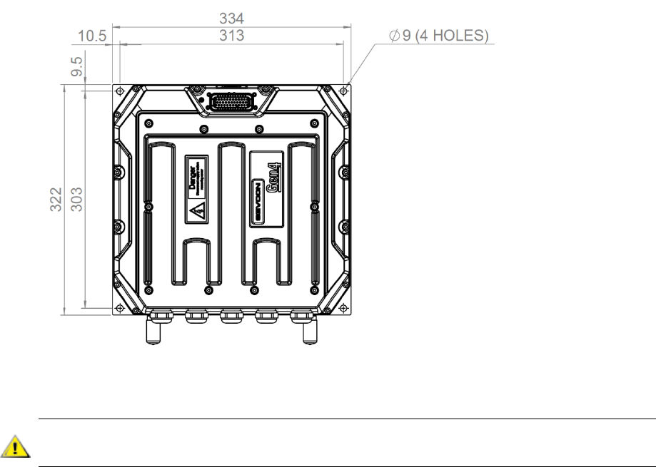
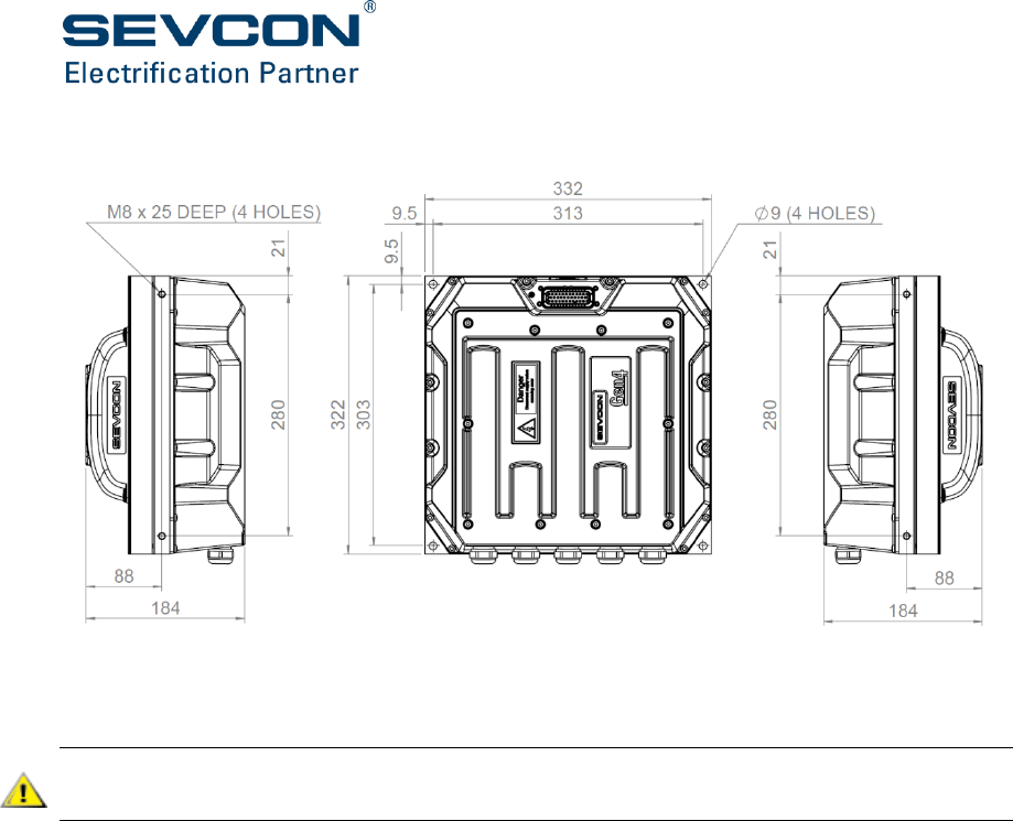
Mounting hole pattern:
Liquid Cooled model:
The inverter should not be used as a stressed member.
Flatness of mounting surfaces: < 0.2 mm
Failure to comply with this flatness specification can cause deformation of the frame and damage
to the product.
Equipment Required
4 x M8 socket cap head bolts (minimum strength 4.8), nuts and spring washers. Bolts
need to be long enough to pass through 20mm of Gen4 Size 8 base plate and your
mounting surface thickness.
T hand-socket wrench or Allen key
Recommended torque setting: 11 Nm ± 2 Nm
3-4
Fan Cooled model:
The inverter should not be used as a stressed member.
Flatness of mounting surfaces: < 0.2 mm
Failure to comply with this flatness specification can cause deformation of the frame and damage
to the product.
Equipment required:
If the 4 x dia 9mm base holes are used:
4 x M8 socket cap head bolts (minimum strength 4.8), nuts and spring washers. Bolts
need to be long enough to pass through 20mm of Gen4 Size 8 base plate and your
mounting surface thickness.
T hand-socket wrench or Allen key
Recommended torque setting: 11 Nm ± 2 Nm
4 x M8 threaded side holes are provided on the side of the base plate as an alternative means of
mounting the inverter. If this method is used:-
4 x M8 socket cap head bolts (minimum strength 4.8), nuts and spring washers. Bolts need to
long enough to pass through any mounting framework or chassis and provide >16mm of thread
engagement into the base plate.
Recommended torque setting: 11 Nm ± 2 Nm

Installation
Doc No: 177/52701 3-5
Rev: 3.3
Cooling requirements
To ensure you get the maximum performance from your Gen4 Size 8 controller:
Keep it away from other heat generating devices on the vehicle
Maintain its ambient operating temperature below the specified maximum (see
‘Operating environment’ on page 4-9). Various cooling options are available to assist with
this.
The cooling method for a particular controller depends on controller part number. The options
are:
1- Liquid-cooled. This option provides the most effective cooling, if adequate heat exchange
from coolant to ambient is provided. A water-glycol mixture with a flow-rate of 2
litre/minute should be sufficient to meet the ratings given in this manual.
2- Fan-cooled finned heatsink. This option provides effective cooling of approx 0.05K/W
provided adequate airflow is maintained.
Running the inverter without coolant while in a fault condition is potentially dangerous and should
not be done for extensive periods.
3-6
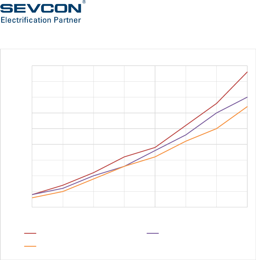
Water Glycol Pressure Drop.
0
0.005
0.01
0.015
0.02
0.025
0.03
0.035
0.04
0.045
23456789
Pressure (Bar)
Flow Rate (l/min)
Flow Rate vs Pressure Drop
Evo5 Beta Baseplate @ 20°C P_DP
(Bar)
Evo5 Beta Baseplate @ 40°C P_DP
(Bar)
Evo5 Beta Baseplate @ 60°C P_DP
(Bar)
Installation
Doc No: 177/52701 3-7
Rev: 3.3
EMC guidelines
The following guidelines are intended to help vehicle manufacturers to meet the requirements
for Electromagnetic Compatibility. Any high speed switch is capable of generating harmonics at
frequencies that are many multiples of its basic operating frequency. It is the objective of a good
installation to minimise, contain or absorb the resultant emissions. All wiring is capable of acting
as a receiving or transmitting antenna. Arrange wiring to take maximum advantage of the
structural metal work inherent in most vehicles. Link vehicle metalwork with conductive braids.
General measures
Power cables
Use screened power cable for all connections to the motor and the battery. Where cables pass
through metal enclosures, such as at the motor and battery, use metal cable glands to connect
the cable screen to the enclosure, ensuring that the various enclosures are linked with conductive
braid to the vehicle chassis. The Gen4 Size 8 itself is equipped with a metal gland plate for
connecting the motor and battery cable shields to the heatsink of the Gen4 Size 8 controller.
Route all cable within the vehicle framework and keep as low in the structure as is practical - a
cable run within a main chassis member is better screened from the environment than one
routed through or adjacent to an overhead guard. Keep cables short to minimize emitting and
receiving surfaces. Shielding by the structure may not always be sufficient - cables run through
metal shrouds may be required to contain emissions.
Parallel runs of cables in common circuits can serve to cancel emissions - the battery positive and
negative cables following similar paths is an example. Tie all cables into a fixed layout and do not
deviate from the approved layout in production vehicles. A re-routed battery cable could negate
any approvals obtained.
The cable manufacturers’ recommendations for minimum bend radius should always be
followed.
Keep power cables at least 300 mm from signal cables.
Signal cables
Keep all wiring harnesses short and route wiring close to vehicle metalwork. Keep all signal wires
clear of power cables and consider the use of screened cable. Keep control wiring clear of power
cables when it carries analogue information - for example, accelerator wiring and speed
feedback. Tie all wiring securely and ensure it always follows the same layout.
Measures required for specific signals
Battery power cables
Use screened cables. Use metal cable glands and connect the screen of the cable to the gland.
Cables should be as short as possible. Minimise the loop area of the B+ and B- wiring. A common
mode ferrite choke may be required.

3-8
Motor power cables
Use screened cables. Use metal cable glands and connect the screen of the cable to the gland.
Cables should be as short as possible. Minimise the loop area of the M1 M2 M3 wiring. A common
mode ferrite choke may be required
Motor encoder connection, types AB, UVW and Sin-Cos
The encoder cable must be as short as possible. A multi-core screened cable should be used. The
inner cores should be used for the encoder supply and encoder ground and the AB or UVW or
Sin-Cos signals. The cable screen should be connected to the control OV terminal. Ensure that
the screen does not connect the motor chassis back to the control OV terminal to avoid motor
power cable current returning through the encoder cable screen.
Motor encoder connection, resolver types
By “resolver” we mean a device consisting of a primary excitation winding (driven by a 10kHz
sinusoidal carrier signal generated by the Gen4 Size 8) and two secondary windings where the
carrier signal is modulated at the rotational frequency by the sine and cosine of the rotor angle
respectively.
The encoder cable must be as short as possible. Separate twisted-pair screened cables should be
used for the primary excitation and the sine and cosine secondary signals. The inner cores should
be used for the sinusoidal signals. The cable screen should be connected to the control 0V
terminal. Ensure that the screens do not connect the motor chassis back to the control 0V
terminal to avoid motor power cable current returning through the encoder cable screen.
CAN bus
A multi-core screened cable should be used. The inner cores must be twisted pairs. One twisted
pair should be used for CANH and CANL. The other twisted pair should be used for CAN supply.
Ensure that there is a common ground connection for all nodes on the CAN bus. If there is a node
on the bus which is galvanically isolated from the Gen4 Size 8 controller then the CAN ground on
this node must be connected to the Gen4 Size 8 controller control 0V. The cable screen should
be connected to the control 0V terminal at the Gen4 Size 8 controller
Keyswitch
The keywire should be as short as possible. Minimise the loop area of the loop formed by the
keyswitch, keyswitch supply and the control OV return wire. Do not connect additional loads to
the keyswitch wire.
Contactor drivers
Minimise the loop area formed by the contactor driver output and the contactor supply +. Use of
twisted pair will reduce emissions. Use of screened cable with the screen connected to control
OV will further reduce emissions. Generally, contactors driven with a configured PWM signal
produce higher emissions than a contactor driven from a fixed DC voltage.

Installation
Doc No: 177/52701 3-9
Rev: 3.3
Throttle input
The throttle input is referenced to the controller control 0V connection, it is therefore very
important that the throttle ground connection goes directly to the control 0V terminal on the
controller. Ensure that there is no common ground path for the throttle with the keyswitch power
connection, contactor drivers or any other power or switching loads on the vehicle. Screened
cable for the throttle supply and wiper may be required for higher levels of immunity, the screen
should be connected to control 0V.
Additional measures
Where it has not been possible to meet the required EMC specifications using the standard
measures listed above it may be necessary to use one or more of the following measures:-
Use of screened cable for all control connections
Use of a Faraday cage around the controller and motor
Addition of an LC filter on the keyswitch supply
A common mode ferrite choke for all the small signal connections will attenuate common
mode emissions
Problems to avoid
EMC is a complex subject and on a typical vehicle there are many potential radiators and
recievers. Measures taken on a vehicle to improve EMC can unitentionally make the situation
worse.
Beware of devices that are connected to the small signal wiring which have a significant
(> 10 nF) capacitance to vehicle chassis. The capacitance to vehicle chassis can cause
currents to flow out of the Gen4 Size 8 controller along the signal wiring to the device
and back to the controller via the vehicle chassis.
When using screened cable beware of generating ground loops in which currents may be
induced or which may cause noise currents to flow via unintended paths.
3-10
Connecting power cables
See also the section on EMC.
Battery and motor connections
Cables carrying high AC currents are subject to alternating forces and may require support in the
cable harness to avoid long-term fatigue.
Use screened power cables sized to suit the controller and application (see below)
M8 crimp ring lugs
Crimp tool
M8 wrench
Torque setting: 11 Nm ± 2 Nm
Installing cables at a different torque level to that recommended can result in poor electrical
connection and risk of terminal overheating / fire.
Consider cable routing before making connections.
Keep cable runs short
Minimize current loops by keeping positive and negative cables as close together as
possible.
Route cables away from the LED if you intend to make this visible under normal operating
conditions.
Connect your power cables using the bolts supplied. They are sized to clamp one ring lug
thickness. Use a longer bolt if you are fastening more than one ring lug. You need thread
engagement of at least 10 mm and the maximum penetration is 15 mm.
If you use a bolt which is too long, damage to the terminal and overheating of the connection may
occur. If you use a bolt which is too short and there isn’t enough thread engagement you may
damage the threads.
Screened cables and metal screened cable glands
A metal gland plate is fitted to the controller. Under no circumstances should the gland plate be
removed.
Installation
Doc No: 177/52701 3-11
Rev: 3.3
When using metal cable glands ensure that the spring contact fingers within the gland connect to
the cable screen.
Ensure that all high voltage power cables are electrically isolated from the cable glands on the
Gen4 Size 8
Under no circumstances should any of the cable screens be connected to any power terminal or
live conductor. Ensure that the cable screen is electrically isolated from the live inner conductor
and the cable termination.
The metal cable gland locknut should be tightened to the metal cable gland through the cover and
screeing plate to a torque of 12 Nm ± 1.0 Nm
Chassis conection to heatsink.
The base plate of the Gen4 Size 8 must be connected electrically to the chassis of the vehicle. The
cross section of the connection must be equal or larger than the cross section of the incoming DC
traction supply.
For some vehicle standards (as the Gen4 Size 8 earth leakage current is > 5 mA), it is required to
fit a second earth connection between base plate and chassis. When using terminated shielded
motor cables, this can be achieved by fitting an earth connection between motor case and vehicle
chassis. If in doubt, contact Sevcon for further advice.
Fitting the Terminal Cover
Clean the gasket and contact area of any grease and debris contamination with a suitable cleaning
agent.
Ensure the lid seal is correctly positioned in its groove
Position the cover ensuring it sits flat against the seal
Fit the x10 M4 screws (provided).
Torque setting: 1.5Nm ± 0.1 Nm
Cable sizes
When deciding on power cable diameter, consideration must be given to cable length, grouping
of cables, the maximum allowable temperature rise and the temperature rating of the chosen
cable.
The following table (Table 2) gives guidance on the cable size needed for various currents in
screened power cable, not grouped with other cables, in 30 °C ambient with 60 °C temperature
rise on the cable surface.
3-12
Gen4 Size 8 average (rms) current
Cable sizes
metric
US (approx equivalent)
175 A
25 mm2
4 AWG
215 A
35 mm2
2 AWG
275 A
50 mm2
1 AWG
Table 2: Guidance on rating of screened cable
The supplied cable gland has a maximum cable diameter of 16.5mm.
Fuse rating and selection
The traction supply must be fused to protect the vehicle wiring and the Gen4 Size 8 in the event
of a fault. Recommended ratings :-
Fuse current rating 425A
Fuse voltage rating 600V dc
Installation
Doc No: 177/52701 3-13
Rev: 3.3
Signal wiring
Assemble your wiring harness using wire of the sizes recommended below and the Sevcon loose
connector kit (P/N 661/27091). The use of twisted pair and in some cases twisted-screened cables
is recommended for the speed sensor and CANbus wiring.
To make a connection, gently push the connector housing onto the appropriate mating half on
the Gen4 Size 8. Never force a connector. Connectors are keyed to prevent incorrect insertion.
See also the section on EMC.
Signal wire sizes
Use wire between 0.5 mm² (20 AWG) and 1.5 mm² (16 AWG) for all signal wiring. Single twisted
pair cable is readily available in 0.5 mm² (20 AWG).
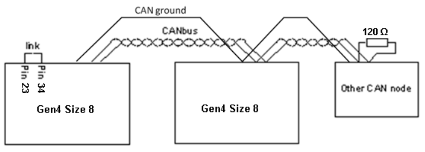
CANbus termination
See also the section on EMC.
If your system has more than one CAN node, connect the nodes in a ‘daisy chain’ arrangement
(Figure 5) and terminate the connections of the two end nodes with a 120 Ω resistor. If the end
node is a Gen4 Size 8, link pins 22 or 23 and 34 on the customer connector, a 120 Ω resistor is
built into the controller. If you have a single node system the termination resistor should be
connected so that the bus operates correctly when configuration tools are used.
Figure 5: CAN Node Termination
3-14
Signal connections
Do not use contactors which have built in ‘economiser’ circuits, the internal circuits are not
compatible with the controller and may cause malfunction or damage. The same power reduction
can be achieved with a standard coil by using the configurable pull-in and hold voltage settings.
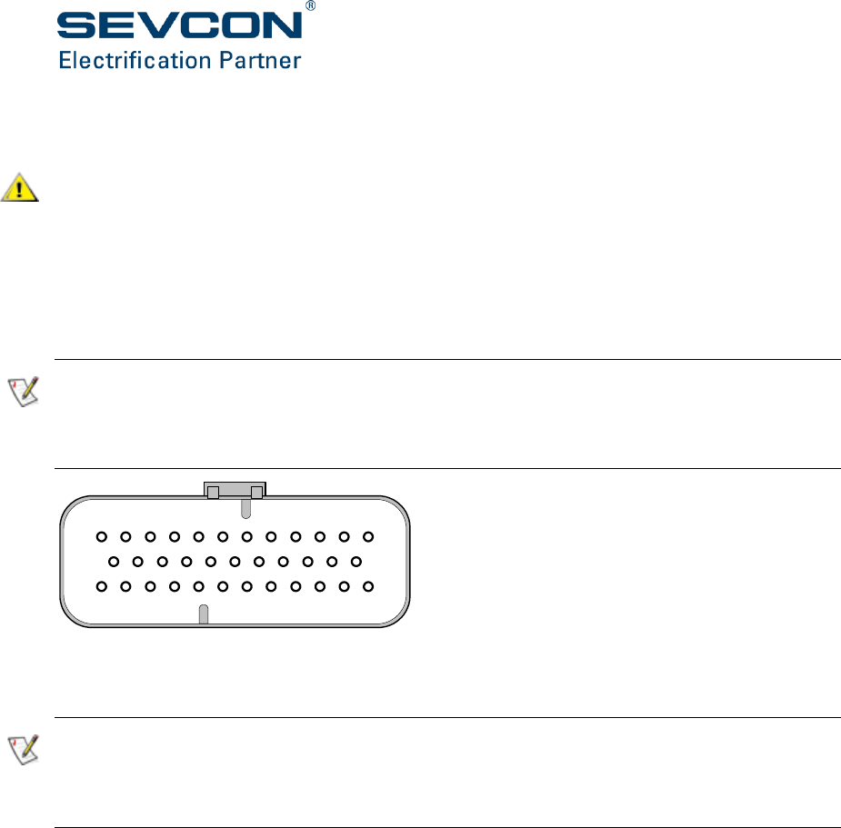
Signal connections are made to Gen4 Size 8 via a 35 way AMPSeal connector.
There are a small number of differences between “Alpha” prototypes and “Beta” production
units. The most important difference is the introduction of “Pulsed Digital Output” and “Pulse
Enable Input” functions.
Gen4 Size 8 Beta controllers will not operate the motor unless a suitable input signal (square-
wave, amplitude 10V, frequency 1kHz, duty cycle 50%) is supplied to the “Pulse Enable Input” pin.
A suitable signal can be supplied by linking Pulsed Digital Output to Pulse Enable Input on the 35-
way customer connector.
Figure 6: Customer Connector
Pins are protected against short-circuits to the control logic supply positive or negative terminals.
There is an exception to the protection for the Pusled Digital Output on the initial production of
Gen4 Size 8 Beta controllers. Initial production Beta controllers do not have protection for short-
circuit of the Pulsed Digital Output to the control logic positive supply. Contact Sevcon for further
details of the status of the protection.
Inserting contacts into connector housing pierces the sealing diagram to make the seal to the
wire. To maintain IP rating, unused positions must be sealed with appropriate hardware
(available from Tyco) if a contact is inserted and then subsequently removed.
35
12
13 23
24
1

Installation
Doc No: 177/52701 3-15
Rev: 3.3
Pin
Name
Type
What to connect
Maximum
rating
Comment
1
Key switch
in (Vc)
Power
From ‘dead’ side of
key switch via suitable
fuse
V = 24V
(nominal)
I = 7A
(Total of all
contactor
output
currents
plus 1.0A)
This input supplies power
from the low voltage
source for all the logic
circuits.
The unit cannot operate
without “Key switch in”
supply.
Referred to as Vc in this
table.
2
Contactor
out 1
Out
To the switched low
side of contactor or
valve coil.
Contactor out 1
usually drives the line
contactor.
(DO NOT USE WITH
CAPACITIVE LOADS).
2.0A per
output,
subject to a
limit of 6A
for the total
of all the
outputs.
V = Vc
This output provides low
side voltage or current
control to the load
depending on
configuration.
The output goes low or is
chopped to activate the
load. It goes high (to Vc) to
de-activate the load.
3
Contactor
out 2
Out
To the switched low
side of contactor or
valve coil.
Contactor out 1
usually drives the line
contactor.
(DO NOT USE WITH
CAPACITIVE LOADS).
2.0A per
output,
subject to a
limit of 6A
for the total
of all the
outputs.
V = Vc
This output provides low
side voltage or current
control to the load
depending on
configuration.
The output goes low or is
chopped to activate the
load. It goes high (to Vc) to
de-activate the load.
4
Contactor
out 3
Out
To the switched low
side of contactor or
valve coil.
Contactor out 1
usually drives the line
contactor.
(DO NOT USE WITH
CAPACITIVE LOADS).
2.0A per
output,
subject to a
limit of 6A
for the total
of all the
outputs.
V = Vc
This output provides low
side voltage or current
control to the load
depending on
configuration.
The output goes low or is
chopped to activate the
load. It goes high (to Vc) to
de-activate the load.

3-16
Pin
Name
Type
What to connect
Maximum
rating
Comment
5
Pot. 1
wiper in
(AIN1_B)
Analog
From potentiometer
1(B) wiper.
V = 9.5 V
Zin = 22 kΩ
Suitable for
potentiometers in the
range 500 Ω to 10 kΩ, or
voltage-output device
(e.g. Sevcon linear
accelerator)
0 to 5 V or 0 to 10 V.
Ensure that at least 0.5V
margin exists between
the maximum valid
throttle and the wire-off
threshold
6
Pot. 2
wiper in
(AIN2_B)
Analog
From potentiometer
2(B) wiper.
V = 9.5 V
Zin = 22 kΩ
Suitable for
potentiometers in the
range 500 Ω to 10 kΩ, or
voltage-output device
(e.g. Sevcon linear
accelerator)
0 to 5 V or 0 to 10 V.
Ensure that at least 0.5V
margin exists between
the maximum valid
throttle and the wire-off
threshold
7
Resolver
Excitation-
Analog
To the primary of the
motor’s resolver (if
fitted)
V = 7.2Vpk-
pk
I = 100mA
8
Resolver
Excitation+
Analog
To the primary of the
motor’s resolver (if
fitted)
V = 7.2Vpk-
pk ( 2.5V
rms)
I = 100mA
9
Encoder
power
supply +
Power
To the positive supply
input of the speed
encoder
I = 100 mA
V = 0V to
+10V, set in
software
Check the speed encoder
you use is compatible
with Gen4 Size 8. See page
6-14 for configuration
details.
10
CAN
ground
Power
To the ground of the
external CAN bus

Installation
Doc No: 177/52701 3-17
Rev: 3.3
Pin
Name
Type
What to connect
Maximum
rating
Comment
11
CAN High
Comms
CANbus High signal
V = 5 V
Maximum bus speed 1
Mbits/sec
Alternative connection to
pin 12
12
CAN High
Comms
CANbus High signal
V = 5 V
Maximum bus speed 1
Mbits/sec
Alternative connection to
pin 11
13
Control 0V
Power
Logic power supply
ground connection
0V
14
Function in
“Alpha”:
Digital
Input 2
Digital
From digital switch
input 2.
In a basic
configuration this is
usually the reverse
switch.
Type A
V = Vc
See Table 4:
Impedance
at Digital
Input Pins
See note to Table 4:
Impedance at Digital
Input Pins
Function in
“Beta”:
Pulsed
Digital
Output
Out
Connect to Vehicle
Control Unit (VCU)
input with pull-up to
provide a 1kHz 50%-
duty pulse output
indicating controller
healthy.
V = Vc
Current 1A
This pin is used as Pulsed
Digital Output from Beta
version onwards
15
Function in
“Alpha”:
Digital
Input 4
Digital
From digital switch
input 4.
Type B
V = Vc
See Table 4:
Impedance
at Digital
Input Pins
See note to Table 4:
Impedance at Digital
Input Pins

3-18
Pin
Name
Type
What to connect
Maximum
rating
Comment
Function in
“Beta”:
Digital
Input 2
Digital
From digital switch
input 2.
In a basic
configuration this is
usually the reverse
switch.
Type A
V = Vc
See Table 4:
Impedance
at Digital
Input Pins
See note to Table 4:
Impedance at Digital
Input Pins
16
Function in
“Alpha”:
Digital
Input 6
Digital
From digital switch
input 6.
Type B
V = Vc
See Table 4:
Impedance
at Digital
Input Pins
See note to Table 4:
Impedance at Digital
Input Pins
Function in
“Beta”:
Digital
Input 4
Digital
From digital switch
input 4.
Type B
V = Vc
See Table 4:
Impedance
at Digital
Input Pins
See note to Table 4:
Impedance at Digital
Input Pins
17
Pot. 1
wiper in
(AIN1_A)
Analog
From potentiometer
1(A) wiper.
V = 9.5 V
Zin = 22 kΩ
Suitable for
potentiometers in the
range 500 Ω to 10 kΩ, or
voltage-output device
(e.g. Sevcon linear
accelerator)
0 to 5 V or 0 to 10 V.
Ensure that at least 0.5V
margin exists between
the maximum valid
throttle and the wire-off
threshold

Installation
Doc No: 177/52701 3-19
Rev: 3.3
Pin
Name
Type
What to connect
Maximum
rating
Comment
18
Pot. 2
wiper in
(AIN2_A)
Analog
From potentiometer
2(A) wiper.
V = 9.5 V
Zin = 22 kΩ
Suitable for
potentiometers in the
range 500 Ω to 10 kΩ, or
voltage-output device
(e.g. Sevcon linear
accelerator)
0 to 5 V or 0 to 10 V.
Ensure that at least 0.5V
margin exists between
the maximum valid
throttle and the wire-off
threshold
19
Encoder A
input
Digital
pulse /
Analog
A channel of AB type
encoder, SIN from
SIN/COS or resolver
type encoder
10V for AB
type
encoder
5V for
SIN/COS,
Resolver
Sin Hi
Controller must be set up
correctly for the motor
speed feedback type. Only
one of AB, SIN/COS and
resolver can be used at
the same time.
20
Encoder B
input
Digital
pulse /
Analog
B channel of AB type
encoder, COS from
SIN/COS or resolver
type encoder
10V for AB
type
encoder
5V for
SIN/COS
Resolver
Cos Hi
Controller must be set up
correctly for the motor
speed feedback type. Only
one of AB, SIN/COS and
resolver can be used at
the same time.
21
Encoder
power
supply -
Power
To the negative
supply input (0 V) of
the speed encoder
I = 100 mA
V = 0.5 V
We recommend the use
of screened cable for the
encoder wiring. Connect
the screen to this pin only
along with the negative
supply.
22
CAN Low
Comms
CANbus Low signal
V = 5 V
Maximum bus speed 1
Mbits/s.
Alternative connection to
pin 23

3-20
Pin
Name
Type
What to connect
Maximum
rating
Comment
23
CAN Low
Comms
CANbus Low signal
V = 5 V
Maximum bus speed 1
Mbits/s.
Alternative connection to
pin 22
24
Protected
key-switch
Power
To supply the high
side of contactor or
valve coils.
V = Vc
Use to supply coils
controlled by pins 2 – 4.
25
Digital
Input 1
Digital
From digital switch
input 1.
In a basic
configuration this is
usually the forward
switch.
Type A
V = Vc
See Table 4:
Impedance
at Digital
Input Pins
See note to Table 4:
Impedance at Digital
Input Pins
26
Function in
“Alpha”:
Digital
Input 3
Digital
From digital switch
input 3.
In a basic
configuration this is
usually a ‘drive
enable’ switch, e.g.
foot switch.
Type A
V = Vc
See Table 4:
Impedance
at Digital
Input Pins
See note to Table 4:
Impedance at Digital
Input Pins
Function in
“Beta”:
Digital
Input 3
Digital
From digital switch
input 3.
In a basic
configuration this is
usually a ‘drive
enable’ switch, e.g.
foot switch.
Type B
V = Vc
See Table 4:
Impedance
at Digital
Input Pins
See note to Table 4:
Impedance at Digital
Input Pins

Installation
Doc No: 177/52701 3-21
Rev: 3.3
Pin
Name
Type
What to connect
Maximum
rating
Comment
27
Function in
“Alpha”:
Digital
Input 5
Digital
From digital switch
input 5.
Type B
V = Vc
See Table 4:
Impedance
at Digital
Input Pins
See note to Table 4:
Impedance at Digital
Input Pins
Function in
“Beta”:
Pulse
Enable
Input
Digital
Connect 1kHz 50%
duty pulse train to
allow power frame
functionality to be
enabled. If this input
is absent or outside
specified range then
the Gen4 Size 8 power
frame will be
disabled.
Internal
pull-up
resistor 6k8
to 15V.
Minimum
amplitude
8V.
Maximum
amplitude
Vc.
This pin is used as Pulse
Enable Input from Beta
version onwards.
For stand-alone operation
it may be connected to
pin 14 (Pulsed Digital
Output) so that the
controllers own “healthy”
output will allow the
power frame to be
enabled.
28
Analogue
input 3
(AIN3)
Analog
ue
To motor
temperature
thermistor (PTC type)
V = 13V
I = 3mA
Zout = 4.7kΩ
29
AIN1 Vcc
Power
To supply
potentiometer or
analogue input device
1
I = 100 mA
V = 0V to
+10V, set in
software
Check the analogue input
device or pot you use is
compatible with the
voltage selected. See page
6-14 for configuration
details.
30
AIN2 Vcc
Power
To supply
potentiometer or
analogue input device
2
I = 100 mA
V = 0V to
+10V, set in
software
Check the analogue input
device or pot you use is
compatible with the
voltage selected. See page
6-14 for configuration
details.

3-22
Pin
Name
Type
What to connect
Maximum
rating
Comment
31
Encoder
“U” input
Digital
pulse /
Analog
U channel of UVW
type encoder; or the –
ve terminal of the SIN
coil of resolver.
V = 10V for
UVW
Resolver Sin
Low
Controller must be set up
correctly for the motor
speed feedback type.
UVW and resolver are not
compatible at the same
time.
32
Encoder
“V” input
Digital
pulse /
Analog
V channel of UVW
type encoder; or the –
ve terminal of the COS
coil of resolver.
V = 10V for
UVW
Resolver
Cos Low
Controller must be set up
correctly for the motor
speed feedback type.
UVW and resolver are not
compatible at the same
time.
33
Encoder
“W” input
Digital
pulse /
Analog
V channel of UVW
type encoder
V = 10V
typical
Controller must be set up
correctly for the motor
speed feedback type.
34
CAN
terminatio
n
Comms
To terminate a Gen4 Size 8 CAN node
link pin 22 to pin 34. This connects a
120Ω termination resistor, mounted
inside the controller, across the
CANbus.
Make the connection only
if the Gen4 Size 8 is
physically at the end of
the CANbus network (see
‘CANbus termination’ on
page 3-13.
35
CAN supply
Power
To supply external
devices referenced to
CAN ground
V = 24V
I = 100 mA
Referenced to CAN
ground. Isolated from
Control 0V.
Table 3: Connector A pin out and wiring information
Digital Input Type
Impedance to Vc
Impedance to Control 0V
A
9k
9k
B
13k
9k
Table 4: Impedance at Digital Input Pins
Note to Table 4:
Configure the digital input switches as active-high (switched to +24 V) or active-low (switched to
0 V). Configuration applies to all digital input switches (1 to 8) i.e. they are all active-high or all
active-low. See section Digital inputs (page 6-14) for more details.
When a switch is open the digital input pin sits at 0.5 x Vc. The input sinks current in active-high
configurations and sources current in active-low configurations.

CHAPTER 4:
SPECIFICATION
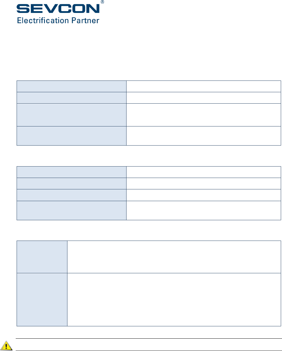
4-2
Electrical
Input voltage – control supply
Nominal working voltage:
12 V to 24 V ( 12 V only on air cooled version)
Working voltage limits:
8 V to 36 V ( max 15 V on air cooled version)
Supply voltage droop:
Vnom to 0.5 x Vnom for 10 ms
Vnom to 0 V for 1 ms
Input protection:
Input protected against reverse connection of battery by
input diode
Input voltage – traction supply
Nominal working voltage:
128 V to 350 V
Working voltage limits:
80 V to 400 Vdc
Non-operational overvoltage limits:
0 V to 450 Vdc
Input protection:
Input protected against reverse connection of battery by
control of the line contactor
Output protection
Output current:
Reduced automatically from peak to continuous rating depending on the
time a peak load is applied to the controller (see Figure 7 on page 4-3).
Reduced automatically if operated outside normal temperature range.
Short-circuit:
Protected against any motor phase to B- or B+ at power-up.
Protected against any motor phase to another motor phase at any time
during operation.
At switch-on Gen4 Size 8 detects valid output loads are present before
applying drive current.
Repetitive short circuits may damage the controller.

Specification
Doc No: 177/52701 4-3
Rev: 3.3
Output ratings
The rating achievable in a particular application must be checked.
Gen4 Size 8 Air-cooled
Ratings at 25°C ambient and air inlet at 25°C.
Maximum output current (boost) 400A rms
Maximum output current (rated 2 minutes) 300A rms
Continuous output current (1hr rated) 165A rms
Figure 7: Output current for various durations of current demand, air cooled
Gen4 Size 8 Liquid-cooled
Ratings at 25 °C ambient and water-glycol at 2.5 litre/min with inlet temperature 30 °C.
Maximum output current (boost) 400A rms
Maximum output current (rated 2 minutes) 300A rms
Continuous output current (1hr rated) 190A rms
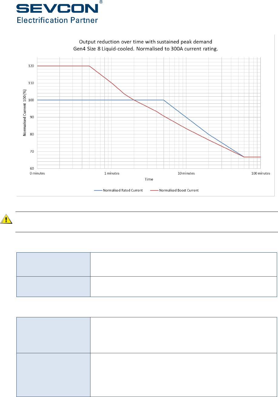
4-4
Figure 8: Output current for various durations of current demand, liquid cooled
Regular repetitive operation of the inverter up to limits of its performance ratings will result in a
reduction on the operating lifetime of the product
CAN interface
CAN protocol:
CANopen profiles DS301, DS401 and DSP402 are supported.
Physical layer uses ISO11898-2.
Baud rates supported:
1 Mbits/s (default), 500 kbits/s, 250 kbits/s, 125 kbits/s, 100
kbits/s, 50 kbits/s and 20 kbits/s.
Control inputs and outputs
Digital inputs:
4 digital switch inputs (software configurable polarity).
Active low inputs < 2.6V, active high inputs > Vb – 2.6 V
Note: Digital inputs 5 and 6 are reserved for future use.
Analog inputs:
4 general purpose inputs which can be used for 2-wire
potentiometers or dual throttle type devices.
Motor thermistor input
All analog inputs can also be used as digital inputs.

Specification
Doc No: 177/52701 4-5
Rev: 3.3
Inductive drive outputs:
(DO NOT USE WITH
CAPACITIVE LOADS).
3 configurable PWM outputs. Use in voltage or current control
mode.
Voltage-controlled:
Continuous sink current = 2A
Peak current limited to < 2.5A
Open-circuit detection (Iout < 0.1 A) is a configurable option
Short-circuit detection (Iout >0.2 A) when drive is in “off” state
Voltage-controlled (PWM) mode allows contactors with a rating
less than Vnom to be used (range 24 V to Vnom).
Current-controlled:
Current output configurable between 0 and 2A
Motor speed sensor
inputs:
Quadrature AB encoder signal inputs provided for control of
induction motors
UWV digital position sensor or sin-cos analogue position sensor or
resolver inputs provided for control of permanent magnet motors
Resolver excitation
Two outputs, Exc+ and Exc-, provide excitation to a speed feedback
resolver. Each output is 7.2V max pk-pk ( 2.5V rms), 100 mA,
protected against short-circuit. Consult the ‘Resolver’ section in the
System Design section of this document for important information
about resolver feedback.
Pulsed Digital Output
Open-drain output. Provides 1 kHz 50%-duty pulsed current sink
when the controller is healthy and no safety problem has been
detected. In stand-alone applications the controller may monitor
its own output using the Pulse Enable input. In VCU applications
the VCU can use the output to determine the safe operation of the
controller.
Pulse Enable Input
Input for 1 kHz 50%-duty pulsed voltage source or open-collector
transistor. Input amplitude can be between 8 V and Vc. A pull-up
to 15 V is provided so that open-collector outputs may be used.
The controller power frame will not operate if this input is missing
or outside specification.

4-6
Isolation
Boundary
Class
Over voltage
Category
Nom
Voltage
Impulse
Rating
Type test
voltage
withstand
CAN to Case
Control to Case
Control to CAN
Basic
CAT III
100 V
500 V
500 Vrms
Power to All Control
Terminals
Reinforced
CAT II
600 V
6 kV
3200 Vrms
Power to Case
Basic
CAT II
600 V
4 kV
1600 Vrms

Specification
Doc No: 177/52701 4-7
Rev: 3.3
EMC
Radiated emissions:
EN12895 (Industrial Trucks – Electromagnetic Compatibility)
EN 55022:1998, 6, class B
EN 12895:2000, 4.1 Emissions. When part of a system with a motor
operating,
FCC Part 15, Radiated Emissions. Meets the standards given in FCC
Part 15, Section 15.109:
ISO 11452:2007 as an Electronic Sub-Assembly (ESA).
ISO 11451:2007 (for vehicles)
UNECE Reg 10 (limits for ESAs and vehicles)
Conducted emissions:
No mains port, therefore not required
Susceptibility:
Performance level A (no degradation of performance) or level B
(degradation of performance which is self-recoverable) subject to
the additional requirement that the disturbances produced do not:
affect the driver’s direct control of the truck
affect the performance of safety related parts of the truck
or system
produce any incorrect signal that may cause the driver to
perform hazardous operations
cause speed changes outside limits specified in the standard
cause a change of operating state
cause a change of stored data
Radiated RF field:
EN 61000-4-3, 5.1 Test Level: user-defined test level of 12 V/m
EN 12895:2000, 4.2 Immunity
EN 61000-4-6, Table 1 - Test Levels
ISO 11452:2007 as an Electronic Sub-Assembly (ESA).
ISO 11451:2007 (for vehicles)
Electrical fast transient:
EN 61000-4-4, Table 1 - Test Levels, Level 2

4-8
Electrostatic discharge:
EN 12895:2000, 4.2 Electrostatic Discharge
4 kV contact discharge
8 kV air discharge
ISO 10605:2008
15 kV contact discharge without permanent damage
25 kV air discharge without permanent damage
8 kV contact discharge (recoverable loss of function)
15 kV air discharge (recoverable loss of function)
Electrical surge:
EN 61000-4-5:1995, Table A.1 – Selection of Test Levels, Class 3
Regulatory compliance
Designed to meet:
EN1175-1:1998 (which covers EN1726 for the controller)
ISO 3691
UL583
ASME/ANSI B56.1:1993
ISO 6469 Road vehicles. Requirements for safety
UNECE Reg 100 Electric vehicles - Construction & safety
Designed to meet in
future:
BS ISO 26262:2011 Road vehicles - Functional safety, when
configured as a Motor Slave
Initial production of Gen4 Size 8 Beta controllers does not meet ISO 26262 but it is intended to do
so in future. Check with your local Sevcon representative for the status of ISO 26262
implementation.
X and Y Capacitance
X capacitance (DC+ to DC-)
1880 µF
Y Capacitance (DC Link to Heatsink
28nF

Specification
Doc No: 177/52701 4-9
Rev: 3.3
Mechanical
Operating environment
Operating
temperature:
Liquid cooled:
-30 °C to +25 °C (no current or time derating)
+25 °C to +80 °C (no current derating, but reduced time at rated
operating point)
+80 °C to +90 °C and -40 °C to -30 °C (with derating)
When operated with liquid-cooled heatsink, the maximum coolant
inlet temperature shall be 40 °C and the maximum coolant
temperature rise shall be 25 °C.
Fan cooled:
The operating range for the fans is -10 °C to +70 °C
Non-operation
temperature:
Liquid cooled:
-40 °C to +85 °C (can be stored for up to 12 months in this ambient
range)
Fan cooled:
The storage temperature for the fans is -30 °C to +70 °C
Humidity:
95% at 40 °C and 3% at 40 °C
Ingress of dust and
water:
Liquid cooled: IP66
Fan cooled:
The fans are rated IP55
Thermal shock:
EN60068-2-14, Test N/A
4-10
Shock and vibration
Repetitive shock:
50 G peak 3 orthogonal axes, 3+ and 3– in each axis, 11 ms pulse width
Drop test:
BS EN 60068-2-32:1993 Test Ed: Free fall, appendix B, Table 1
Bump:
40 G peak, 6 ms, 1000 bumps in each direction repetition rate 1 to 3
Hz.
Vibration:
3 G, 5 Hz to 500 Hz
Random vibration:
20 Hz to 500 Hz, acceleration spectral density 0.05 G2/Hz (equivalent
to 4.9 Grms)
Weight
Controller weight
Liquid cooled
10 kg
Fan cooled
15 kg
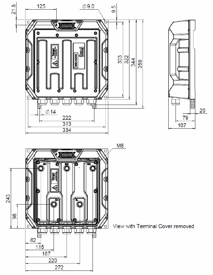
Specification
Doc No: 177/52701 4-11
Rev: 3.3
Dimensions Gen4 Size 8
Liquid Cooled Model:
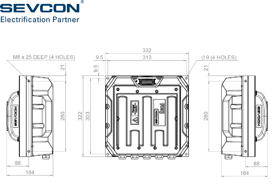
4-12
Fan Cooled Model:

CHAPTER 5: SYSTEM
DESIGN

5-2
Sizing a motor
Information required about the application
To select an appropriate induction motor for an application find or estimate the following
information:
Minimum battery voltage
Maximum motor speed required
Peak torque required at base speed
Peak torque required at maximum motor speed
Continuous (average) motor power output required to perform the work cycle
Peak motor power output required and duration
Include inertia and friction contributed by the motor, as well as any gearing in the drive chain,
when calculating torque and load requirements. If replacing a DC motor with an AC motor in an
existing application, the DC motor torque vs. speed curve is a good starting point to determine
the required ratings.
Motor maximum speed
Determine the maximum motor speed using the required vehicle or pump maximum speeds and
the ratio of any gear box or chain between the motor and the load. Most motor manufacturer
rate induction motors at synchronous speed which is 1,500 and 1,800 rpm for a 4-pole motor
when operated from 50 Hz and 60 Hz line frequencies respectively.
The maximum speed an induction motor can be used at is determined by the limit of the
mechanical speed, typically 4,000 to 6,000 rpm, and the reduction in useful torque at higher
speeds. Increasing losses in the iron of the motor at higher speeds may further limit the maximum
speed. Always check the maximum speed with the motor manufacturer. Check also any
limitations imposed by the maximum frequency of the encoder input signal (see ‘Motor speed
sensor (encoder)’ on page 5-10).
Active Short Circuit Protection
The Gen4 Size 8 controller is capable of driving both Induction and Permanent Magnet AC motors
beyond their base speed, into a region of higher speed ‘field weakened’ operation.
PMAC motors produce an inherent back EMF, which can reach very high levels during high speed
operation. Field weakening is used to keep the back EMF below the level of the DC link power
supply.
In event of a serious system or controller fault during operation above the configured upper
speed threshold, the active short circuit function will clamp the back EMF produced by a rotating
high speed motor. This dissipates the system energy in the motor at the motor short circuit
current.
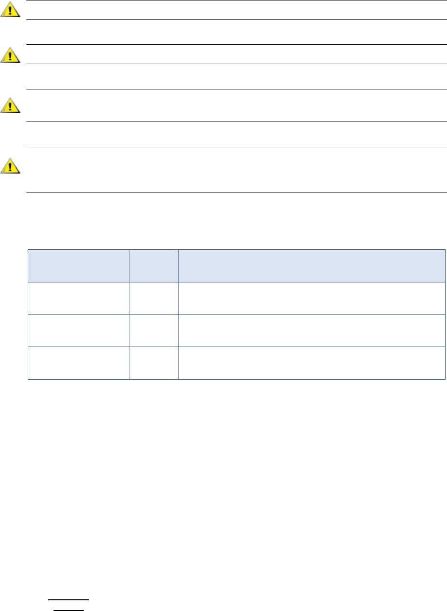
System design
Doc No: 177/52701 5-3
Rev: 3.3
if the peak level of back EMF from a PMAC motor exceeds 450V then the Gen4 Size 8 can damaged.
active short circuit can not operate if the 12V/24V power supply to the Gen4 Size 8 is removed
the active short circuit produced by the motor must be less than the maximum current rating of
the Gen4 Size 8 unit.
The high voltage DC Battery supply to the Gen4 Size 8 will help act as a clamp on maximum back
EMF produced by the motor. Ensure that any contactor/interlocks are not opened during high
speed operation to help ensure that excessive levels of back are not experienced.
Active Short Circuit is configured OFF by default and is configured for use with the following
objects:
Feature
Object
index
Notes
Active Short
configured
4658h
Enable/Disable Active Short Functionality
Active Short Lower
Speed Threshold
4659h
Sets Lower Speed Threshold to exit Active Short Circuit
Active Short Upper
Speed Threshold
4660h
Sets Upper Speed Threshold to start Active Short Circuit
Contact Sevcon for assistance on setting up the active short circuit function if the target motor is
capable of producing a back emf > 450 V peak at the required maximum speed of operation.
Torque required between zero and base speed
Calculate the torque required by the application. Use figures for the work that needs to be done
against friction and gravity, plus those required to accelerate the load inertia and momentum.
Up to rated speed the peak torque that can be supplied when using a correctly specified Gen4
Size 8 is equal to the breakdown torque. Select a motor with a breakdown torque rating greater
than the peak torque required.
Torque required at maximum speed
Calculate the torque as above. As speed increases beyond base speed the maximum torque an
induction motor can supply falls as defined by the following two equations:
In the constant power region;
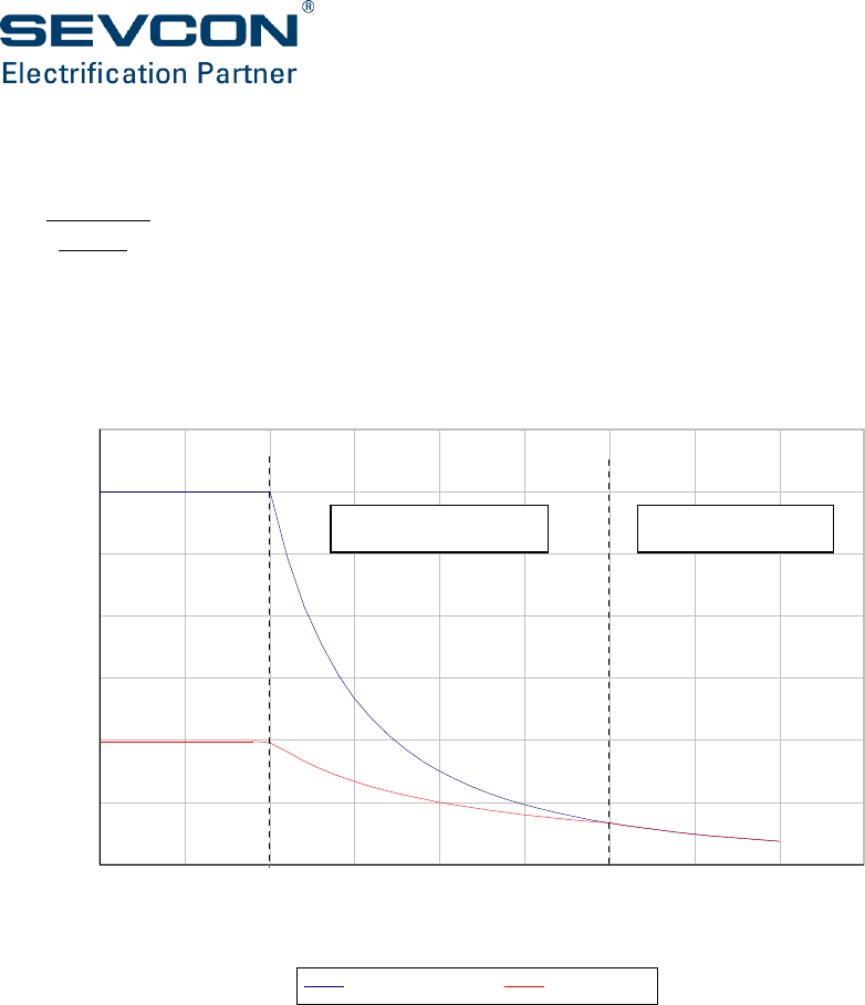
5-4
In the high speed region;
This is shown in Figure 9. Select a motor with a torque rating greater than the peak torque
required.
Figure 9: Torque Speed Curve
Continuous power rating
The required continuous power rating of the motor is governed by the application load cycle over
a shift. Use the maximum RMS current over a period of one hour to determine the motor rating
required. The motor manufacturer will typically specify a 1 hour or continuous rating. Select a
motor whose ratings are equal to or greater than your calculated load over 1 hour.
Peak power rating
The peak power rating required for the application is actually determined by the peak torque
required, as this determines the motor current required. Motor manufacturers will provide S1,
S2 or S3 duty cycle ratings for the motors.
Torque speed curve for a typical induction motor
0
0.5
1
1.5
2
2.5
3
3.5
0 0.5 1 1.5 2 2.5 3 3.5 4 4.5
Speed (pu)
Torque (pu)
breakdown torque rated torque
constant power region
high speed region
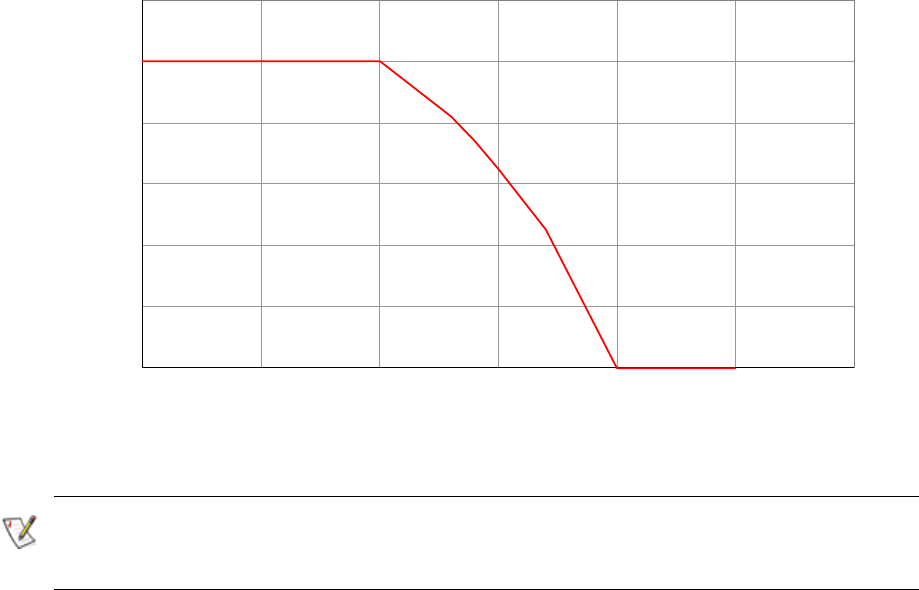
System design
Doc No: 177/52701 5-5
Rev: 3.3
Selecting the Gen4 Size 8 model
Matching motor and controller ratings is not an exact exercise and therefore you may need to
perform iterative calculations. The main considerations when choosing an appropriate Gen4 Size
8 controller are described below.
Current and power ratings considerations
Consider the following when choosing the appropriate Gen4 Size 8 controller:
Ensure the controller chosen matches or exceeds the peak current and average current
requirements of the motor(s) in the application.
Ensure the application can dissipate the waste heat generated by the controller. If the
controller gets too hot it reduces its output, limiting vehicle performance.
Power output restrictions at motor and drive operating temperature limits
A controller protects itself by reducing the current and hence torque available when its
temperature limit is reached (Figure 10).
Figure 10: Current allowed v. Controller Based Temperature
The Gen4 Size 8 also looks at a number of internal temperature measurements and estimates.
These can also influence the thermal cutback operation, depending on installation and operating
duty cycle
0
20
40
60
80
100
120
70 75 80 85 90 95 100
Current allowed (% of maximum)
Base temperature (°C)
Gen4 Cutback Curve

5-6
Circuit configuration
Once motor size is determined the application circuit configuration can be defined. A basic single
traction configuration (Figure 11) is provided as a starting point for new designs. Given the
flexibility of the I/O it is possible to configure a wide range of systems. Refer to ‘Signal
connections’ on page 3-14 to see what each I/O signal is capable of doing as you design your
system.
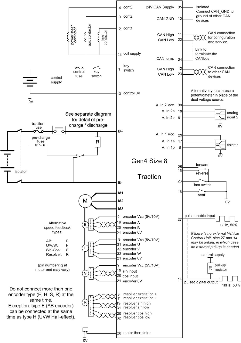
System design
Doc No: 177/52701 5-7
Rev: 3.3
Single traction wiring diagram
Figure 11: Single Traction Wiring Diagram- Gen4 Size 8 Beta

5-8
Figure 11 shows line contactor coil connected to and driven directly from the Gen4 Size 8. This is
only possible if the unit is configured to receive actual battery voltage via the CANBus as part of
a power on start-up sequence.
Twin motor systems
A twin motor system may be powered by two Gen4 Size 8 controllers operating in master–slave
configuration. In this case the necessary commands are transmitted by the master node to the
slave node via the CANbus.
Motors may be operated independently in a combined traction-pump application or operated in
tandem where each motor drives a separate wheel. In this latter case the controller (where there
are two controllers, the controller configured as master):
Assists in the steering of a vehicle by adjusting the torque of each motor dependent on
the steering angle.
Reverses the direction of the inner wheel in order to provide a smaller turning circle. The
speed of the outer wheel is also limited during a turn.
Auxiliary components
Main Contactor and Precharge circuit
Gen4 Size 8 does not support line contactor or precharge functionality. An external device must
be used to isolate the Gen4 Size 8 from the vehicle battery. This external device is also responsible
for any capacitor precharging required to prevent damage to the line contactor tips.
It is recommended that the precharge circuit is connected as shown in Figure 12
The circuit is intended to operate in the following manner:-
When K1 and K2 are not energised resistor R1 ensures that the controller dc bus capacitance is
quickly discharged to a safe voltage.
At startup K1 must be energised, the controller DC bus voltage should be monitored and should
have reached 90% of the battery voltage within 5s.
If the dc bus voltage is more than 90% of battery voltage the main contactor K2 can now be
closed. If the dc bus voltage is too low this indicates a fault and K1 should be de-energised.
The line contactor should be monitored and protected against welding welding during operation.
At shut-down K1 and K2 may be de-energised simultaneously. K1 will connect R1 from B+ to B-
thus discharging the controller dc bus.
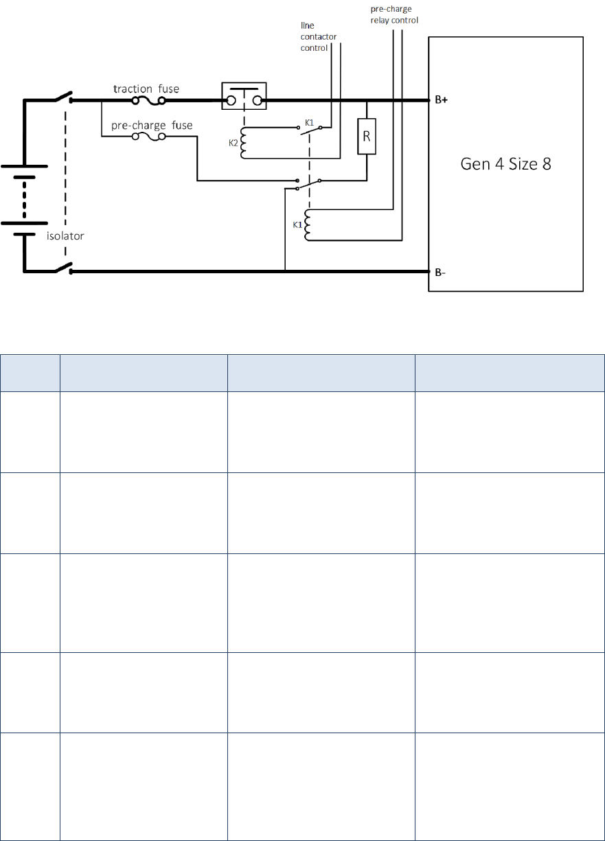
System design
Doc No: 177/52701 5-9
Rev: 3.3
Figure 12: Line contactor and pre-charge wiring diagram
Components required for the precharge and discharge circuit are listed in the following table
Name
Function
Required specification
Comment
F1
Pre-charge fuse
20 A
600 Vdc
Slow blow
F2
Main traction fuse
425A
600 Vdc
Semiconductor fuse
K1
Pre-charge and dis-
charge contactor
Single pole change over
with auxiliary contact
600 Vdc
10 A
Must be wired such that in
the normally closed position
R1 is connected to the B-
terminal.
K2
Main line contactor
Single pole
600 Vdc
500A
Must be interlocked so that
K2 can only close if K1 is
energised.
R1
Pre-charge and dis-
charge resistor
Resistance 100 Ω to 1 kΩ
Pulse voltage 600 V
Energy pulse 200 J
Power 50 W
Must be overload protected
with thermal cut out and or
fuse
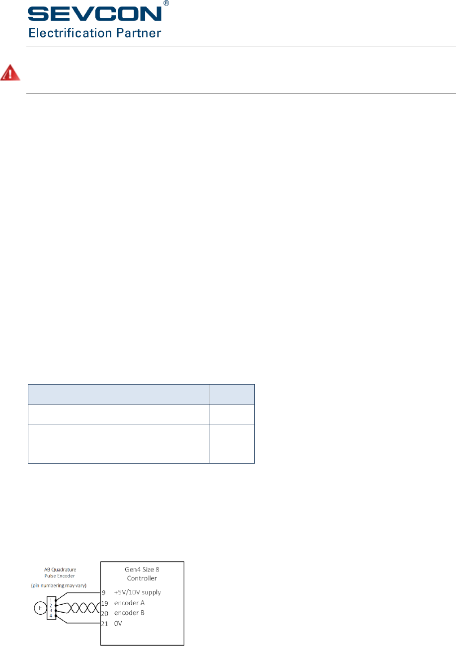
5-10
Failure to use a capacitor precharge circuit may lead to damage to the controller. Failure to use a
discharge circuit may result in the dc bus capacitors remaining charged at hazardous voltages for
several minutes.
Contactors controlled from Gen4 Size 8
The controller can drive any contactor with coil voltages from 12 V to the control supply. It is
worth considering the use of contactors with a rated coil voltage suitable for the lowest expected
operating voltage of the control supply. The contactor drive outputs can be set to voltage-control
mode, in which PWM output is used to maintain the requested coil voltage. Pull-in voltage, pull-
in time and hold-in voltage values are all configurable.
Contactor coils must not be wired to the supply side of the key switch. Use the Protected
Keyswitch pin provided.
35 Way AMPSeal Connector Kit
Kit consists of Gen4 Size 8 mating 35 way AMPSeal connector and pins, Sevcon p/n 661/27901
Emergency stop switch
Refer to the appropriate truck standards.
Key switch fuse F2
Use a fuse rated for the sum of the drive currents plus 1 A for internal circuits. In the following
example there are two contactors each drawing 2 A:
Device
Current
Power steer contactor
2 A
Pump contactor
2 A
Gen4 Size 8 control circuits
1 A
Fuse choice: 5 A.
Motor speed sensor (encoder)
A 4-wire connection is provided for open-collector or current-source quadrature pulse encoder
devices (software configurable). These types of encoder are optimized for accurate speed
measurement, required for efficient control of induction motors.
Figure 13: Sample wiring for an AB quadrature speed encoder

System design
Doc No: 177/52701 5-11
Rev: 3.3
You can use the following types of quadrature encoder, or equivalents:
Type
Output
Supply
Specification
Bearing Type
(SKF and FAG)
Open collector
5 to 24 V DC
64 and 80 pulses per revolution
Dual quadrature outputs
Output low = 0 V (nominal)
HED Type
(Thalheim)
Constant
current
10 V nominal
80 pulses per revolution
Dual quadrature outputs
Output low = 7 mA
Output high = 14 mA
The number of encoder pulses per revolutions (n) and the maximum motor speed (N) are related
to, and limited by, the maximum frequency of the encoder signal (fmax). The following table shows
the maximum motor speed for a given encoder on a 4-pole motor.
Encoder ppr
Maximum motor speed (rpm)
128
6000
80
10000
64
10000
For other types of encoder and motor use the formulae:
with fmax limited to 13.3 kHz, and
Encoder PPR is set at 6090h. Additional encoder configuration (pull-up, supply, etc) is set at 4630h.
Motor commutation sensor
UVW Commutation Sensors
Commutation sensors are designed to measure the position of the rotor shaft within the motor,
rather than its rotational speed. Rotor position information is used for control of permanent
magnet motors, as it allows the controller to energise the motor phases appropriately based on
the measured position of the magnets on the rotor.
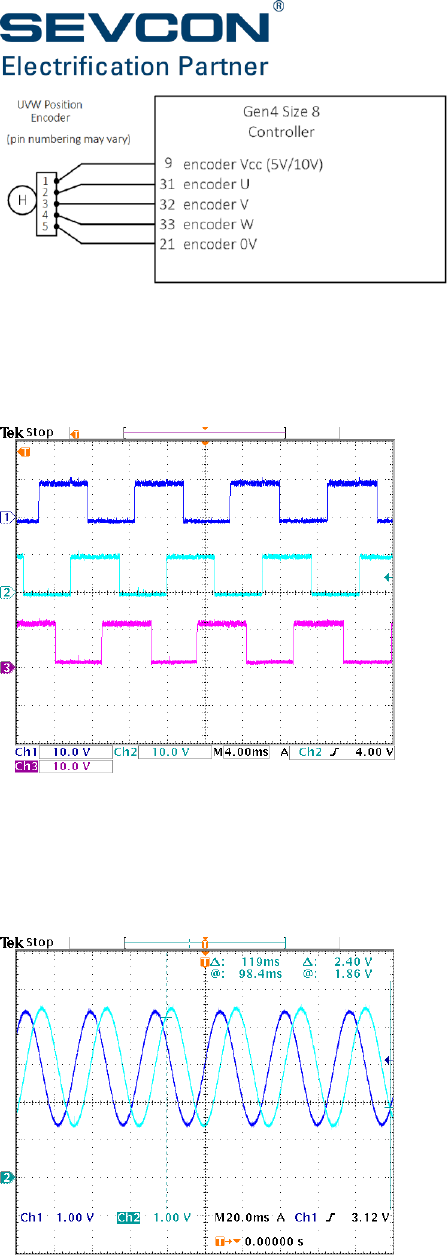
5-12
Figure 14: Sample wiring for a UVW commutation sensor
3 digital inputs are provided for UVW encoders. The encoder should provide one pulse on each
channel per electrical cycle of the motor, and each pulse should be 120° out of phase with the
others and have a 50% duty cycle:
Figure 15: Example pulse train from a UVW commutation sensor
Sin-Cos Commutation Sensor
Analogue sin-cos encoders generate a number of sin and cosine waves per mechanical rotation
of the motor.
Figure 16: Example of signals from a sin-cos position sensor
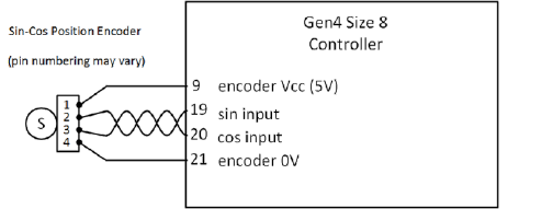
System design
Doc No: 177/52701 5-13
Rev: 3.3
The controller is able to control motors with sin-cos sensors that produce multiple sin and cosine
waves per mechanical rotation. However, it is required that the number of pole pairs in the motor
is an integer multiple of the number of sin-cos waves per rotation. That is to say, the number of
waves per electrical rotation of the motor should be an integer number.
Examples:
an encoder that produces 3 waves per rotation can be used with motors that have 3 pole
pairs, 6 pole pairs, 9 pole pairs, etc…
an encoder that produces 5 waves per rotation can be used with motors that have 5 pole
pairs, 10 pole pairs, 15 pole pairs, etc...
an encoder that produces 1 wave per rotation can be used with motors that have 1 pole
pair, 2 pole pairs, 3 pole pairs, etc…
Figure 17: Sample wiring for a sin-cos commutation sensor
Sin-cos encoders are typically powered by a 5 V supply. Therefore it is important to ensure that
the controller is configured to supply 5 V on pin 9. This should be done by setting the encoder
configuration object dictionary entry at 4630h.
When a Sin-cos encoder is used there should be no connection of other encoder types. Pins 31,
32, and 33 must be left unconnected.
Resolver
The resolver is a speed feedback device which requires a sinusoidal excitation (provided by the
Gen4 Size 8 controller). The speed feedback consists of two pairs of signals: a Resolver Sin pair
and a Resolver Cos pair. These signals consist of the excitation frequency modulated by the sin
or cosine (respectively) of the rotor position.
The following issues are important when selecting a resolver: mechanical, environmental and
electrical specification.
Mechanical specification includes e.g. material; dimensions; max speed; max angular
acceleration; rotor moment of inertia; resistance to shock; resistance to vibration; permitted
axial offset; permitted radial runout (deviation from true circle) of motor shaft.
Environmental specification includes: max operating temperature (including self-heating); IP
rating.
Electrical specification includes: number of pole pairs (p); transformer ratio (Rt); angular error
tolerance; residual voltage; recommended input voltage; recommended operating frequency;
maximum primary current.
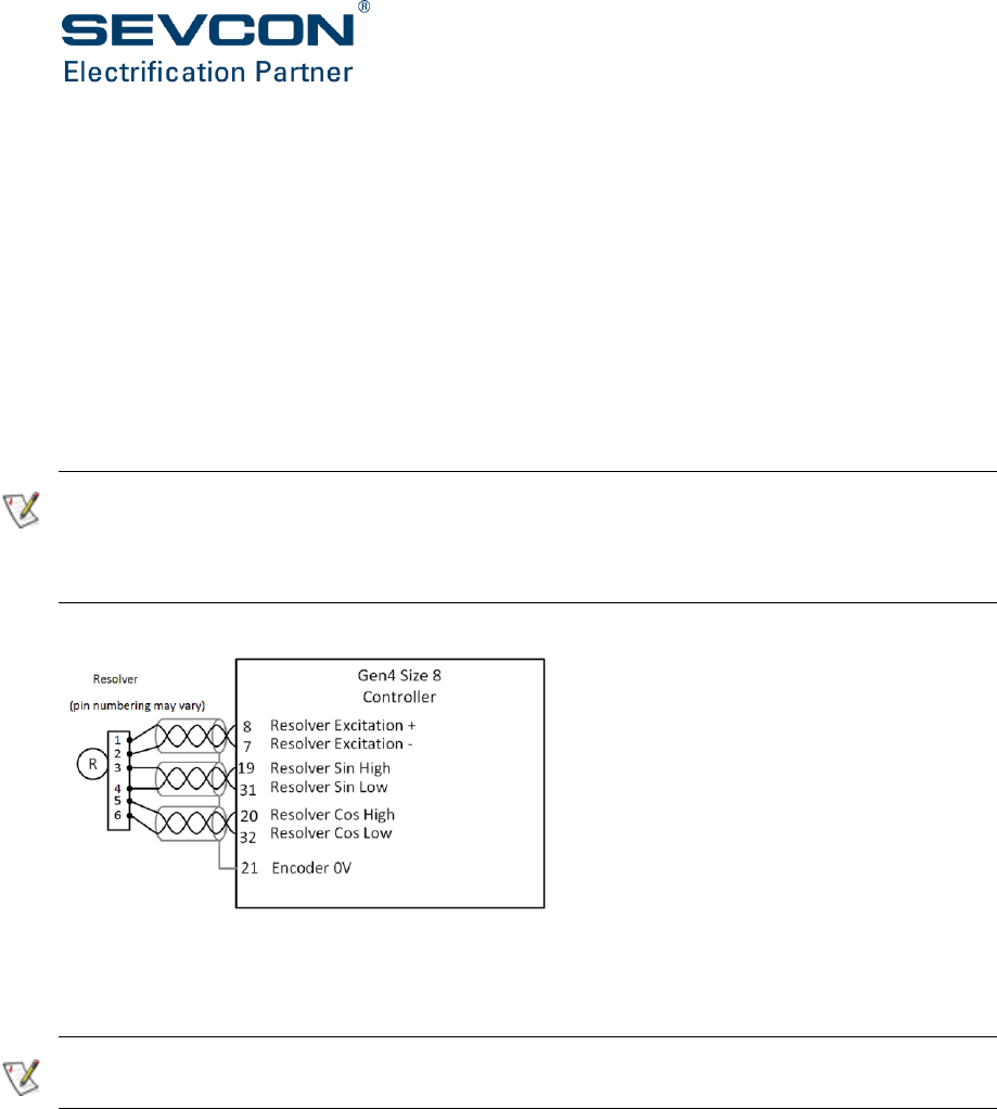
5-14
Regarding mechanical and environmental specification, the user must select a resolver
appropriate to the environment of the application.
Regarding electrical specification, the following features are required of a resolver to work with
the Gen4 Size 8:
Number of pole pairs = 1 or for multi pole pair resolvers a whole number divisor of the number
of motor pole pairs.
Transformer ratio = 0.5 or 0.29 (according to a different Gen4 Size 8 part number)
Excitation frequency = 10 kHz
Excitation voltage = 2.5 Vrms nominal (a resolver specified to 2.5 Vrms or higher will be
acceptable)
Gen4 Size 8 Beta controllers are built specifically to operate with a resolver transformer ratio of
either 0.5 or 0.29. For a particular Gen4 Size 8 model, the resolver transformer ratio cannot be
configured to a value different from the value stated for that model. Contact Sevcon if you require
to use a resolver with a different transformer ratio
Figure 18: Sample wiring for a resolver
Note the screen for the encoders should be open circuit at the motor end but connected to
Encoder 0V at the inverter end.
Only connect a single type of encoder to the Gen4 Size 8 at any given time. One exception is a
supported option to connect both AB and UVW for a PMAC motor.

System design
Doc No: 177/52701 5-15
Rev: 3.3
Initial power up sequence
Incorrectly wired or configured vehicles may behave in unexpected ways. At the end of the following
procedure, only lower the drive wheels to the ground after correct operation of the motor and
encoder has been confirmed.
Checks prior to power up
Follow this checklist prior to applying power to your system:
Jack up the vehicle so that the drive wheels are clear of the ground.
Confirm all connections are tightened to specified level.
Ensure all plugs are fully inserted.
Confirm power wiring connections are made to the correct terminals
(B+, B-, M1, M2 and M3).
Ensure the controller is securely mounted (from a mechanical and thermal perspective).
Ensure there is adequate and correctly ducted airflow for the fan cooled version or
coolant for the liquid cooled version.
Check the routing of cables is safe with no risk of short circuit, overheating or cable
insulation wear due to rubbing.
Checks after power is applied
Apply power and do the following:
Use DVT (see page 6-2) or any configuration tool to complete the configuration process
which starts on page 6-7.
Using the drive controls ensure the wheels rotate in the expected direction. If they do
not, check the motor wiring, encoder wiring and encoder configuration (page 6-14).
It should now be safe to lower the vehicle to the ground and test drive. Proceed with caution.
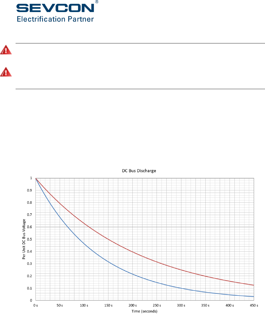
5-16
Discharge sequence after power down
Hazardous voltages will remain on the controller internally and on exposed power terminals for a
period of time after the main power connections have been removed.
Hazardous voltages may remain on the controller internally and on exposed power terminals after
the main battery power connections and keyswitch power supplies have been removed if the
controller is connected to a rotating permanent magnet motor.
Controller discharge profiles
The inverter contains 1.88 mF ± 20% DC Link capacitance.
The following graph shows the standard controller discharge curve which should be observed.
This curve only applies if the discharge circuit in Main Contactor and Precharge circuit is not used
or has been disconnected.
Do not open the unit or work near exposed power terminals until the voltage has reduced to a
safe level.
Figure 19: Standard discharge curve for the Gen4 Size 8 controller
To determine the required time, note the time at which the “Voltage (maximum)” curve crosses
the horizontal gridline corresponding to the supply voltage. Then note the time at which it crosses
the horizontal gridline corresponding to the safe voltage level (normally considered to be 60 V).
The difference between the two times is the safe discharge time period.
System design
Doc No: 177/52701 5-17
Rev: 3.3
To achieve a shorter discharge time the vehicle system designer must ensure that the line
contactor and capacitor precharge circuit also incorporates a discharge circuit which is activated
once the main line contactor is openned.
If the controller is connected to a permanent magnet motor and the motor is rotating the
discharge circuit will be exposed to the rectified back emf even if the controller keyswitch power
supply is turned off.

CHAPTER 6:
CONFIGURATION

6-2
Introduction
This section covers what you need to do to configure Gen4 Size 8’s software once you have
designed and installed your hardware. All of Gen4 Size 8’s parameters have a default value and
the amount of configuration needed is dependent on your particular system.
The main topics are:
DVT configuration tool: installation and use
CANopen: an introduction to the protocol and its use in Sevcon products
An overview of the configuration process outlining what needs to be done and the order
in which it must be done
The configuration steps
DVT configuration tool
DVT is Sevcon’s proprietary configuration tool. It allows the user to monitor, configure and
duplicate the parameters of any Sevcon CANopen node such as the Gen4 Size 10 controller. The
information presented here is an overview only. Contact Sevcon for more information about DVT
and the functions it provides.
DVT functionality
DVT provides the following facilities:
Configuration of controller IO, CANBus, motor parameters & vehicle drive performance
parameters
Loading DCF configuration file into the Sevcon controller
Saving of DCF configuration file from controller to file on computer
Controller status and fault diagnosis
Data logging of controller/motor performance on test bench or vehicle
Update controller firmware
Saving, duplicating and restoring a node’s configuration
You can use DVT to:
Save a node’s configuration. This can be used at some later date to clone the node’s
configuration.
Duplicate a node’s configuration, in real time, to another node on the CANbus.

Configuration
Doc No: 177/52701 6-3
Rev: 3.3
Restore a configuration to a node.
For example, if you want to save the Gen4 Size 10 controller configuration, you will need to
create a DCF file. To do this, open the helper by clicking the icon at the top of the DVT main
window.
Data Logging.
You can use DVT to monitor data or parameters of a Sevcon node in real time and graph the data.
CANopen
This section assumes you have an understanding of CAN and are familiar with its use. If you are
new to CAN or CANopen please refer to the CiA (CAN in Automation) website, www.can-cia.org
for further information.
The following information provides an introduction to the important CANopen terminology used
in this manual and how it relates to the configuration of your Gen4 Size 8 controller.
CANopen protocol
CANopen is a CAN higher layer protocol and is defined in the DS301 ‘Application Layer and
Communication Profile’ specification. All CANopen devices must adhere to this standard. To
provide greater standardization and interoperability with 3rd party devices, Gen4 Size 8 is
designed to use the CANopen protocol for communication on its CANbus and meets V4.02 of
DS301.

6-4
CANopen also supports standardized profiles, which extend the functionality of a device. The
controller supports the following CANopen standardized profiles:
DS401 (V2.1) – Device Profile for Generic I/O Modules
DSP402 (V2.X) – Device Profile for Drives and Motion Control
Object Dictionary
Any device connected to the CANopen network is entirely described by its Object Dictionary. The
Object Dictionary defines the interface to a device. You setup, configure and monitor your Gen4
Size 8 controller by reading and writing values in its Object Dictionary, using a configuration tool
such as Sevcon’s DVT (see page 6-2).
There are two important text files associated with the Object Dictionary. These are:
EDS (electronic data sheet)
An EDS is a text file representation of the Object Dictionary structure only. It contains no data
values. The EDS is used by configuration software such as Sevcon’s DVT to describe the structure
of a node’s Object Dictionary. An EDS for each Gen4 Size 8 model and software version, is
available from Sevcon. The EDS file format is described in the DSP306 – Electronic Data Sheet
Specification.
Each Object Dictionary matches a particular Gen4 Size 8 software revision, and its structure is
hard coded into the controller software.
DCF (Device Configuration File)
This is a text file similar to an EDS except that it contains data values as well as the Object
Dictionary structure.
DCFs are used to:
Download a complete pre-defined configuration to a node’s Object Dictionary.
Save the current configuration of a node’s Object Dictionary for future use.
Communication objects
These are SDO (service data object) and PDO (process data object) as described below. There is
a third object, VPDO (virtual PDO), used by Gen4 Size 8 which is not a CANopen object. It is
described here because its function is important and similar to that of a PDO.
SDO (Service Data Object)
SDOs allow access to a single entry in the Object Dictionary, specified by index and sub-index.
They use the client–server communication model, where the client accesses the data and the
server owns the target Object Dictionary.
SDOs are typically used for device configuration (e.g. via DVT) or for accessing data at a very low
rate.

Configuration
Doc No: 177/52701 6-5
Rev: 3.3
PDO (Process Data Object)
PDOs are used by connected nodes (for example in a twin motor configuration) to exchange real
time data during operation. PDOs allow up to 8 bytes of data to be transmitted in one CAN
message.
They use the producer-consumer communication model, where one node (the producer) creates
and transmits the PDO for any connected nodes (consumers) to receive. Transmitted PDOs are
referred to as TPDOs and received PDOs as referred to as RPDOs.
VPDO (Virtual Process Data Object)
VPDOs do a similar job as PDOs for data exchange, but internal to a single Sevcon node. They are
unique to Sevcon and are not part of CANopen.
Network Configuration
General
If auto-configuration cannot be used or if additional, non-Sevcon nodes need to be added, use
the following procedure to setup the network:
Set node ID and baud rate in 5900h to the required values. Node IDs must be unique, and the
baud rate must be the same for each node.
Set SYNC COB-ID in 1005h to 0x40000080 for the master node, or to 0x00000080 for all slave
nodes. Bit 30 is set to indicate to a node if it is the SYNC producer. Only one node in the network
should be configured as the SYNC producer. This should normally be the master. On the SYNC
producer, set the SYNC rate in 1006h.
Set the EMCY message COB-ID to 0x80 + node ID in 1014h.
EMCY COB-IDs must be configured correctly to ensure the master handles EMCYs from slaves
correctly.
Configure the heartbeat producer rate in 1017h. This is the rate at which this node will transmit
heartbeat messages.
Configure the heartbeat consumer rate in 1016h. A consumer should be configured for each node
to be monitored.
Heartbeats must be configured correctly for correct network error handling. The master node
should monitor heartbeats from all slave nodes. Slave nodes should, at a minimum, monitor
heartbeats from the master node.
Loss of CANbus communication from any one node must cause a heartbeat fault to occur.
On standalone systems with non-CANopen nodes attached, hardware CANbus fault detection
should be enabled at 5901h. CANbus fault detection is automatically enabled for multi-node
CANopen systems.
Configure additional SDO servers. An SDO server allows another CANopen device to SDO
read/write from a node’s object dictionary. Each node has one default SDO server (1200h) which

6-6
is reserved for communication with configuration tools like DVT or the calibrator. Another 3 SDO
servers can be configured at 1201h to 1203h. These should be used as follows:
On slave nodes, configure a server to allow the master node to communicate.
If there is a display in the system, configure a server to allow the display access.
On the master node, configure SDO clients at 1280h to 1286h. There must be one client for each
slave node. The SDO clients must be configured to match the corresponding SDO server on each
slave.
On the master node, list all slave node IDs at 2810h.
Configure RPDOs (1400h to 17FFh) and TPDOs (1800h to 1BFFh) appropriately for the system. See
section, Manual object mapping (page 6-11), for more information.
Configure the RPDO timeout function if required. See section PDO mapping (page 6-12) for more
information.
3rd Party CANopen Devices
At power up, the Gen4 Size 8 master will communicate with all slave nodes to identify which
nodes are Sevcon devices and which are not using the vendor ID in 1018h. This instructs the Gen4
Size 8 how to handle EMCY messages from each node.
Gen4 Size 8 knows how to react to EMCYs (faults) from Sevcon slaves and can take appropriate
action. Gen4 Size 8 does not know how to react to EMCYs from 3rd party devices, so the required
fault reaction to 3rd party device EMCYs must be set at 2830h.
Configuration
Doc No: 177/52701 6-7
Rev: 3.3
Configuration process overview
Electric vehicles can be dangerous. All testing, fault-finding and adjustment should be carried out
by competent personnel. The drive wheels should be off the floor and free to rotate during the
following procedures.
We recommend saving parameter values by creating a DCF, before making any alterations so you
can refer to, or restore the default values if necessary. Do this using DVT.
This part of the manual assumes you have a vehicle designed and correctly wired up with a
CANopen network setup. Before you can safely drive your vehicle it is necessary to go through
the following process in the order presented:
Step
Stage
Page
1
Motor characterization
6-8
2
I/O configuration
6-10
3
Vehicle performance configuration
6-18
4
Vehicle features and functions
6-34
Access authorization
To prevent unauthorized changes to the controller configuration there are 5 levels of
accessibility: (1) User, (2) Service Engineer, (3) Dealer, (4) OEM Engineering and (5) Sevcon
Engineering. The lowest level is (1), allowing read only access, and the highest level is (5) allowing
authorization to change any parameter.
To login with DVT, select User ID and password when prompted.
To login with other configuration tools write your password and, optionally, a user ID to object
5000h sub-indices 2 and 3. The access level can be read back from sub-index 1. The password is
verified by an encryption algorithm which is a function of the password, user ID and password
key (5001h).
The password key allows passwords to be made unique for different customers. The user ID also
allows passwords to be made unique for individuals.
How NMT state affects access to parameters
Some important objects can only be written to when the controller is in the pre-operational
state. DVT takes Gen4 Size 8 in and out of this state as required.
If you are not using DVT you may need to request the CANopen network to enter pre-operational
before all objects can be written to.
To enter pre-operational, write ‘1’ to 2800h on the master node.
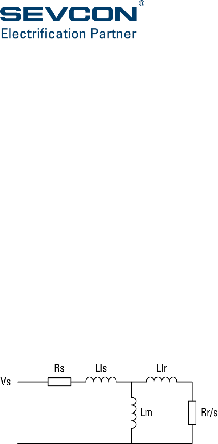
6-8
To restore the CANopen network to operational, write ‘0’ to 2800h.
The controller may refuse to enter pre-operational if part of the system is active: for example, if
the vehicle is being driven. The request is logged in the EEPROM however, so if power is recycled
the system won’t enter operational and remains in pre-operational after powering up.
The NMT state can be read at 5110h where 05 = operational and 7F = pre-operational.
Motor characterization
Ensure you have completed the CANopen network setup process.
Determining induction motor parameters
To provide optimum motor performance Gen4 Size 8 needs the basic motor information
normally found on the name plate as well as the following information:
A value for each of the electrical parameters of the induction motor as shown in Figure
20.
The magnetic saturation characteristics of the motor in the constant power and high
speed regions.
Current and speed control gains.
Figure 20: AC motor single-phase equivalent circuit
To determine these parameters use one of the following methods:
Ask the motor manufacturer to provide the data and enter it in the Object Dictionary at
4640h and 4641h. Also enter encoder data at 4630h and 6090h and motor maps at 4610h
to 4613h.
Use the motor name plate data and the self characterization routine provided by Gen4
Size 8 and DVT (described below).

Configuration
Doc No: 177/52701 6-9
Rev: 3.3
Self characterization
The self characterization function will cause the motor to operate. Ensure the vehicle is jacked up,
with the driving wheels off the ground and free to turn, before starting the test.
The motor self-characterisation process allows a user to determine the electrical parameters
required for efficient control of AC induction motors using a Gen4 Size 8 controller connected to
a PC or laptop running characterisation software. For further information, please contact your
local Sevcon representative.
At time of writing, SCWiz is not yet compatible with Gen4 Size 8. Induction motor parameter
characterisation therefore needs to be carried out using a lower voltage (48 V or 80 V) Gen4
controller.
Determining PMAC motor parameters
Gen4 Size 8 supports both surface magnet and interior (buried) magnet types of PMAC motor.
Motors which do not exhibit saliency (generally surface magnet motors) can be controlled via a
standardised control scheme based on motor parameters. These are a subset of the induction
motor parameters and are found in in the Object Dictionary at 4641h. Motors which are salient
require piece specific configuration which is only supported directly through Sevcon applications.
Please contact Sevcon Applications for more detail.
The PMAC control functions are provided by a different build of software and although a large
proportion of the functionality is consistent with induction machine control there are
parameters, which are not necessary for PMAC configuration. Only the following are required,
typically provided by the motor manufacturer.
6-10
Feature
Object indices
Notes
Current control
gains
4641h,13
4641h,15
4641h,33
4641h,34
PI control gains for inner current control loops
Maximum stator
current.
4641h,2
Maximum stator current in Amps
Back EMF
constant
4641h,18
Back EMF constant of the motor in line to line RMS Volts
per radian per second
Stator Inductance
4641h,10
Phase inductance in Henries
Minimum field
weakening
current
4641h,3
Minimum field weakening current in Amps
Stator Inductance
4641h,10
Phase inductance in Henries
Maximum
modulation index
4641 h,30
Maximum modulation index allowed during drive
Field weakening
control gains
4641 h,25
4641 h,26
Tunable parameters to compensate for motor parameter
inaccuracy during field weakening.
Power limit table.
4611 h
Static limit lookup table of maximum output torque with
respect to motor speed.
Encoder
Configuration
4630h, 6090h
Encoder configuration.
I/O configuration
Ensure you have completed the CANopen network setup and Motor Characterization processes
described above.
The individual characteristics and mapping of the I/O in your application need to be setup. This
can be done manually, or one of a selection of predefined setups can be selected. Predefines
setups exist for many of the common vehicle functions such as standalone traction, standalone
pump and twin traction.
For manual configuration, it is necessary to use PDOs and VPDOs to map application objects on
the master node (2000h to 24FFh) to the hardware I/O objects on all other nodes (6800h to 6FFFh).
To configure I/O:
Configuration
Doc No: 177/52701 6-11
Rev: 3.3
Configure PDOs and VPDOs to map application objects on the vehicle master node to
hardware I/O objects on other nodes
Setup each hardware I/O object, including wire-off protection.
Manual object mapping
To enable the controller to perform the functions required in your system it is necessary to map
object to object (e.g. a measured input signal mapped to a steer operation).
This is achieved by setting up PDOs (node to node mapping) and VPDOs (internal mapping on
each controller) as described below.
Apply mapping to Gen4 Size 8 as follows:
Standalone controllers: setup VPDOs only
Networked controllers: setup VPDOs and PDOs
Before starting the mapping process it is a good idea to draw out a map of what you want to do.
The amount of mapping required depends on the electrical wiring of your vehicle. Check to see if
the default settings satisfy your needs before making changes.
VPDO mapping
VPDO mapping is defined by objects in the range 3000h to 3FFFh as shown in the table below.
Use DVT, or any other configuration tool, to access these objects.
Feature
Object indices
Notes
Motor
3000h
Used to map the master to the type of local motor
Input mapping
3300h
Used to map digital input signals to application inputs
3400h
Used to map analog input signals to application inputs
Output mapping
3100h
Used to map application outputs to digital output signals
3200h
Used to map application outputs to analog output signals
To help understand how to map internal objects an example VPDO mapping is shown in Figure
21. A digital switch input is mapped to the seat switch function to control the traction application,
i.e. with no seat switch input the vehicle is prevented from moving.
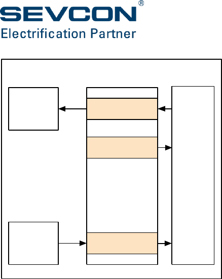
6-12
Figure 21: Example of a digital input mapped to the seat switch via VPDO
The number of sub-indices of each VPDO object depends on the amount of I/O on the device.
For example, 3300h has 14 sub-indices on a device with 8 digital inputs and 5 analog inputs. Sub-
index 0 gives the number of I/O channels in use. In 3300h sub-indices 1 to 8 correspond to the
digital inputs and sub-indices 9 to 14 correspond to the digital state of analog inputs.
To map the local I/O to an application signal object, set the appropriate VPDO sub-index to the
application signal object index. If the seat switch shown in the above diagram was connected to
digital input 4 (bit 3 in 6800h,1), sub-index 4 of 3300h would be set to 2124h.
Some further examples are:
Map FS1 to read the value of digital input 8 (connector A, pin 11): at 3300h sub-index 8
enter the value 2123h.
Map the electromechanical brake signal to be applied to analog output 2 (customer
connector, pin 7): at 3200h sub-index 2 enter the value 2420h.
The data flow direction between the application signal objects and the local I/O objects depends
on whether they are inputs or outputs. For inputs, the flow is from the local I/O to application
objects, and vice versa for outputs.
Motor VPDOs are slightly different. There are six parameters for each motor, some of which flow
from application to local I/O (control word, target torque and target velocity) and some of which
flow from local I/O to application (status word, actual torque and actual velocity).
PDO mapping
The controller supports 5 RPDOs (receive PDOs) and 5 TPDOs (transmit PDOs). Up to 8 Object
Dictionary entries can be mapped to each PDO. Every PDO must have a unique identifier (COB-
ID).
VPDO
manager
3300h
(VPDO mapping)
2124h
(seat switch)
traction
application
Object Dictionary
seat
switch
Master
6800h [1]
(digital inputs 1-8)
local
I/O
digital
inputs
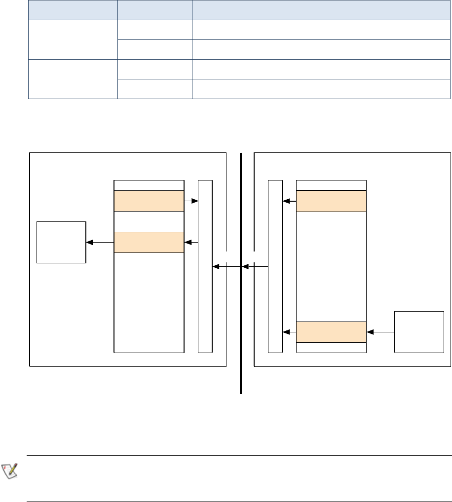
Configuration
Doc No: 177/52701 6-13
Rev: 3.3
Setup RPDOs and TPDOs to transmit and receive events between nodes, and map I/O from one
node to applications in another node.
The easiest way to do this is using DVT. If you are using a 3rd party configuration tool, the relevant
Object Dictionary indices are listed in Table 5.
Feature
Object indices
Notes
Input mapping
1400h-15FFh
RPDO communication parameters
1600h-17FFh
RPDO mapping
Output mapping
1800h-19FFh
TPDO communication parameters
1A00h-1BFFh
TPDO mapping
Table 5: Objects associated with mapping
An example mapping (Figure 22) shows the movement of PDOs in a master-slave configuration
in which a digital input to the slave has been mapped to the seat switch object in the master.
Figure 22: Example of a digital input mapped to the seat switch object via PDO and the CANBus
Gen4 Size 8 supports RPDO timeout fault detection. This can set a warning, drive inhibit or severe
fault depending on the configuration in 5902h.
RPDO timeout can be used for non-CANopen systems which do not support heart beating. By
default, RPDO timeout is disabled, and normal CANopen heart beating protocol (see section
Network Configuration (page 6-5)) is assumed to be used.
CANopen
CANbus
1600 - 8h
(RPDO mapping)
2124h
(seat switch)
PDO
traction
application
Object Dictionary
seat
switch
Master
CANopen
1A00 - 8h
(TPDO mapping)
6800h [1]
(digital inputs 1-8) local
I/O
Object Dictionary
digital
inputs
Slave
(producer)(consumer)
PDO

6-14
Encoder
It is important that the number of encoder pulses per revolution is entered correctly. If this
information is not correct, the controller may not be able to brake the motor effectively.
To configure the encoder:
Configure the type of encoder: UVW, SinCos, single or multipole Resolver, AB, ABUVW
or single channel.
Enter the resolution pulses/rev at 6090h. (Note that if using a UVW or SinCos position
sensor the ppr should be set to 64.)
Check whether the encoder requires controller pull ups enabled (e.g. open-collector
type) and enable pull-ups if needed at 4630h. The default setting is no pull-ups, which is
suitable for current source encoder types.
Set the required encoder supply voltage (from 5 V to 10 V) at 4630h.
If using a UVW, SinCos encoders or resolvers the Encoder Offset also needs to be
configured in 4630h. This is stored in two parts and either can be used to define the
offset. The first part gives +/- 127° to a resolution of 0.00390625 and the second gives
+/- 1024° to a resolution of 0.0625. Both are stored at 4630h.
For SinCos encoders the minimum and maximum voltages for each channel and the
number of waves per mechanical revolution also need to be configured.
Digital inputs
The state of the digital inputs can be read at object 6800h.
Digital inputs are either all active low (switch return to battery negative) or all active high (switch
return to battery positive). A mixture of active low and active high inputs is not possible. The
default setting is active low.
To configure digital inputs:
Set active high/low logic at 4680h.
Set digital input polarity at 6802h. This is used to configure normally closed/open
switches.
Analog inputs
The analog input voltages can be read at object 6C01h. Voltages are 16-bit integer values with a
resolution of 1/256 V/bit.
Although each input is usually assigned a specific task by default, any of the inputs can accept a
variable voltage or a potentiometer. Analog inputs can also be used as additional digital inputs.
There are 2 variable analog supplies at pins 29 and 30. Set the supply voltage at object 4693h.
The following table summarises the analog inputs and any special features:

Configuration
Doc No: 177/52701 6-15
Rev: 3.3
Name
Object
Pin
Usage
Analog Input 1 A
6c01h,1
17
Input from external voltage source or 3-wire pot
wiper. Use pin 29 as supply for 3-wire pot.
Analog Input 1 B
6c01h,2
5
Analog Input 2 A
6c01h,3
18
Input from external voltage source or 3-wire pot
wiper. Use pin 30 as supply for 3-wire pot.
Analog Input 2 B
6c01h,4
6
Motor thermistor
6c01h,5
28
Use for motor thermistor input or 2-wire pot input.
Has internal pull-up.
Wire-off detection
Enable wire-off detection at 46C0h to 46C4h. For each input specify the allowable range of input
voltages. To disable, set the ranges to maximum.
Motor thermistor input
You can connect a thermistor sensor to the Motor thermistor input or a switch to any digital
input.
Type
Specification
PTC Silistor
KTY84, PT1000, or equivalent
Switch
Connected to a general purpose digital input
To setup go to object 4620h:
Configure as none, switch or PTC thermistor
For KTY84 thermistor, set the PTC type to KTY84.
For non-KTY84 PTC thermistor, set the PTC type to User Defined and then set the
expected voltages at 100 ˚C (high temperature voltage) and 0 ˚C (low temperature
voltage). The Gen4 Size 8 will linearly interpolate temperature with voltage.
If you are using a switch select the digital input source
Read the measured motor temperature (PTC) or switch operation at object 4600h.
Analog inputs configured as digital inputs
Each analog input can also be used as a digital input.
To configure an analog input as a digital input, set the high and low trigger voltages at object
4690h.
The digital input status object, 6800h, contains enough sub-indices for the digital and analog
inputs. Sub-index 1 is the states of the digital inputs, and sub-index 2 is the states of the analog
inputs converted to digital states.
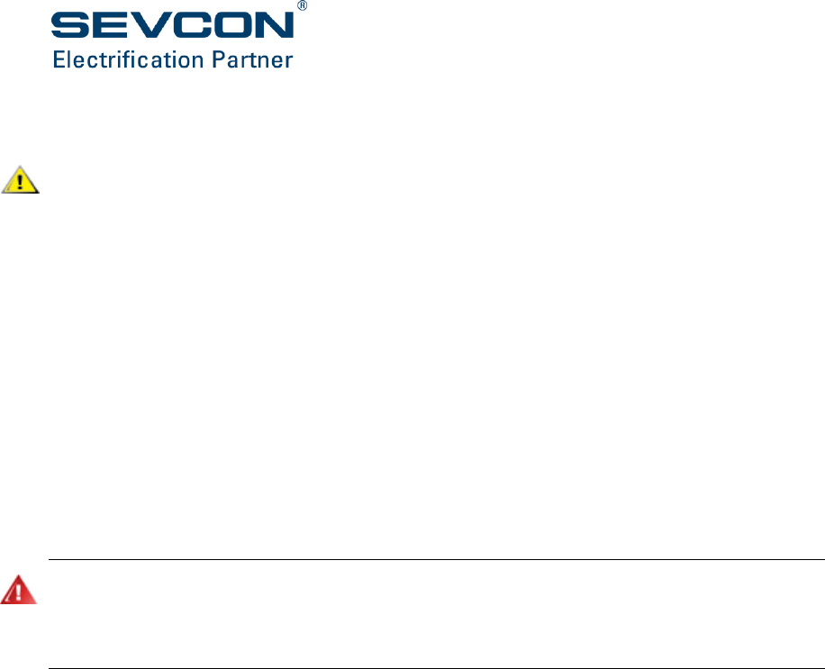
6-16
Analog (contactor) outputs
Do not use contactors which have built in ‘economiser’ circuits, the internal circuits are not
compatible with the controller and may cause malfunction or damage. The same power
reduction can be achieved with a standard coil by using the configurable pull-in and hold voltage
settings.
There are 3 analog outputs which you may map to one or more contactor functions such as:
pump, power steer, electro-brake, external LED, alarm buzzer and horn.
Configure each of the outputs used in your system:
Choose voltage control or current control for each analog output at 46A1h.
(At the time of writing, current controlled devices can only be operated from Gen4 Size
8 by mapping a signal input to the controller from an external 3rd party node).
Set the analog output values at object 6C11h. The value is either a voltage or current
depending on whether the output is voltage controlled or current controlled. Values are
16-bit integers with a resolution of 1/256 V/bit or A/bit.
Error control
It is important that analog outputs on nodes other than the master must have appropriate error
configuration to protect against CANbus faults. This section explains how to configure the outputs
to go to a safe state in the event of a CANbus fault. It is the installers responsibility to define what a
safe state is for each output.
In a CANopen network, the slave node on which the analog (contactor) outputs reside can be
different to the master node which calculates the output value. If the CANbus fails, the master
node is no longer able to control the slave outputs. In this situation, the outputs may need to
change to a safe value. This is achieved with error control.
To configure error control:
Set each output at object 6C43h to use its last set value or the value at 6C44h if the
CANbus fails.
Set values if needed at 6C44h for each output. These values are 32-bit integers, but the
bottom 16-bits are ignored. The top 16-bits give the error value in 1/256 V/bit (or A/bit
for current controlled outputs).
Some examples of typical configurations may be:
Electro-mechanical brake on slave node. If CANbus communication is lost, it may be
desirable to apply the electro-mechanical brake on the slave device. In this case, enable
error control in 6C43h and set the error value in 6C44h to 0.
Power steer contactor on slave node. If CANbus communication is lost, it may be
desirable to leave the power steer output in its previous state. In this case, disable error
control in 6C43h.

Configuration
Doc No: 177/52701 6-17
Rev: 3.3
CANbus communication error lamp on slave node. If CANbus communication is lost, it
may be desirable to activate an output on the slave device. In this case, enable error
control in 6C43h and set the error value in 6C44h to an appropriate voltage for the lamp.
The above examples are for illustration purposes only. It is the responsibility of the installer to
decide on the required state for each output in the event of a CANbus failure.

6-18
Vehicle performance configuration
Ensure you have completed the CANopen network setup, Motor Characterization and I/O
Configuration processes described above.
Safety Interlocks
FS1
The FS1 switch is normally part of the throttle assembly. It closes when the throttle is pressed.
The throttle voltage is ignored until FS1 is closed.
FS1 features are configured at 2914h:
SRO (static return to off): inhibits drive if FS1 is closed for the SRO delay without any
direction (forward or reverse) being selected.
FS1 recycle: forces the operator to lift their foot off the throttle before allowing drive
after a direction change.
Deadman
The deadman switch operates similar to the FS1 switch, whereby, it inhibits drive until it is active.
However, the deadman switch applies the electro-mechanical brake immediately on
deactivation, whereas FS1 waits for the vehicle to stop before applying the brake.
Seat
The seat switch indicates operator presence on the vehicle. Drive is not allowed if this switch is
open. If the seat switch opens during drive for a period longer than the seat switch delay, a fault
is set, disabling drive. To clear a seat fault, close the seat switch, open FS1 and deselect the
forward/reverse switch.
Set the seat switch delay at object 2902h.
Handbrake
If mapped to a digital input, the handbrake switch inhibits drive if the vehicle handbrake is
applied. Controlled roll-off detection is still active when the handbrake is applied in case the
brake fails.
Sequence Fault Masking
If an application does not require it, sequence fault checking can be disabled on selected drive
inputs. This is set at 2918h.
Similarly, drive inputs can be masked when clearing drive inhibit faults. This is set at 291Ah.
These masks must only be applied if the application has other adequate means of protection. It is
the responsibility of the installer to ensure this.

Configuration
Doc No: 177/52701 6-19
Rev: 3.3
Torque mode/speed mode
Speed mode (or speed control) is not recommended for on-highway vehicles as it can cause the
traction motor/wheel to remain locked or brake severely if the wheel is momentarily locked due to
loss of traction on a slippery surface and/or mechanical braking.
The Gen4 Size 8 controller provides both torque and speed control modes. Objects 2900h and
6060h are used to set which mode to use. The default setting is torque mode.
Always ensure 2900h on the master node and 6060h on all the traction nodes (master and slaves)
match otherwise motor signals between the master and slaves may be misinterpreted.
The speed control (speed mode) or speed limit (torque mode) is controlled using PI loops. These
loops are configured at 4651h. The following parameters can be configured:
Standard proportional and integral gains (4651h, 1+2). Used to configure the loops during
normal operation.
Low speed proportional and integral gains (4651h, 3+5). Used to configure the loops at
low speeds (<50 RPM) and during hill hold. These are normally set lower than the
standard gains to dampen oscillation as the vehicle comes to a stop.
Roll back integral gain (4651h, 4). Used to boost the integral term to prevent vehicle roll-
off down inclines, particularly when Hill Hold is enabled. Normally, this gain is higher
than the standard integral gain.
dw/dt gain (4651h, 6). Used to boost the torque output in speed mode, when a large
increase in speed demand occurs. Not used in torque mode.
Integral initialization factor (4651h, 7). Used to initialize the integral term on entry to
speed limit in torque mode. This factor is multiplied by the actual torque to set the
integral term. Not used in speed mode.
These settings affect how driver demands are interpreted by the controller. In torque mode, the
throttle push translates into a torque demand, which is applied to the traction motor. In speed
mode, the throttle push translates to a speed demand. The controller then calculates the torque
required to maintain this speed.
The difference between these control methods is most apparent when driving on an incline. In
torque mode, when the vehicle is driven uphill, the vehicle speed will decrease due to the
increased load. The operator must apply more throttle demand in order to maintain speed. In
speed mode, the controller will apply additional torque in order to maintain the operator’s speed
demand, without the operator having to increase throttle demand.
Throttle
General
The controller can use 2 or 3 wire throttle inputs of the following types:
Linear potentiometer in the range 470 to 10 k
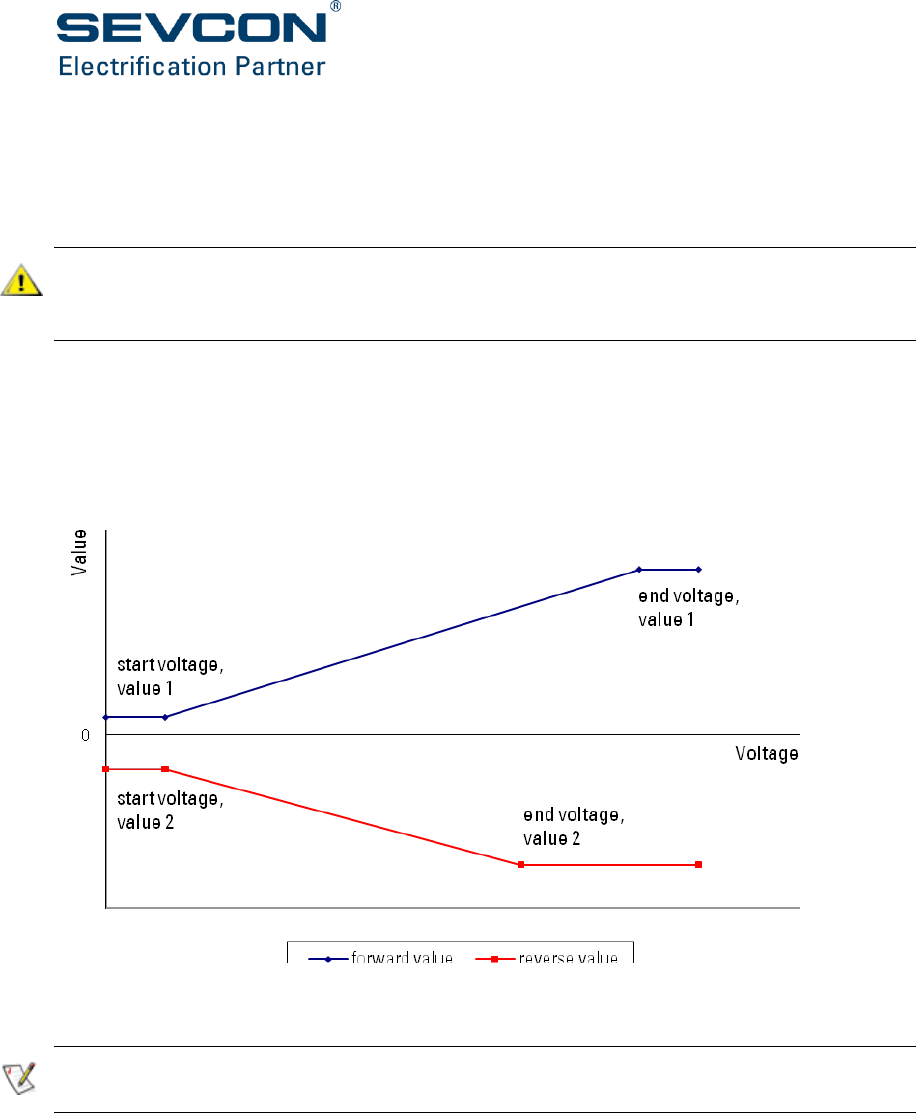
6-20
Voltage source in the range 0V to 10V: compliant with the standard 0..5 V, 0..10 V or
3.5..0 V ranges
To setup throttle inputs see ‘Analog inputs’ on page 6-14. The throttle voltage (2220h) must be
mapped to an analog input.
It is recommended that inputs with wire-off detection are used for the throttle input to detect
wiring faults. This is especially important if a wire-off sets maximum throttle. See section Analog
inputs (page 6-14) for more information.
Setup the characteristics of the throttle at 2910h, sub-indices 2 to 20.
Define the throttle voltage input: this is the relationship between the throttle voltage and the
throttle value. Separate relationships can be specified for forward and reverse. Each relationship
has two points, a start and an end. The points are configured differently for standard and
directional throttles as shown in Figure 23 and Figure 24 respectively.
Figure 23: Standard throttle configuration
If the reverse characteristic is the same as the forward characteristic, just set all the reverse
throttle parameters to 0 in 2910h.
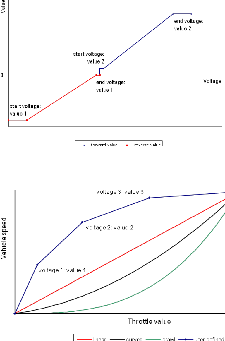
Configuration
Doc No: 177/52701 6-21
Rev: 3.3
Figure 24: Directional throttle configuration
Define the input characteristic: this is a profile to the throttle value and can be linear, curved,
crawl or user-defined as shown in Figure 25. The curved and crawl characteristics give greater
throttle control at low speeds.
Figure 25: Input characteristics
The throttle value calculated from the voltage can be read at 2620h.
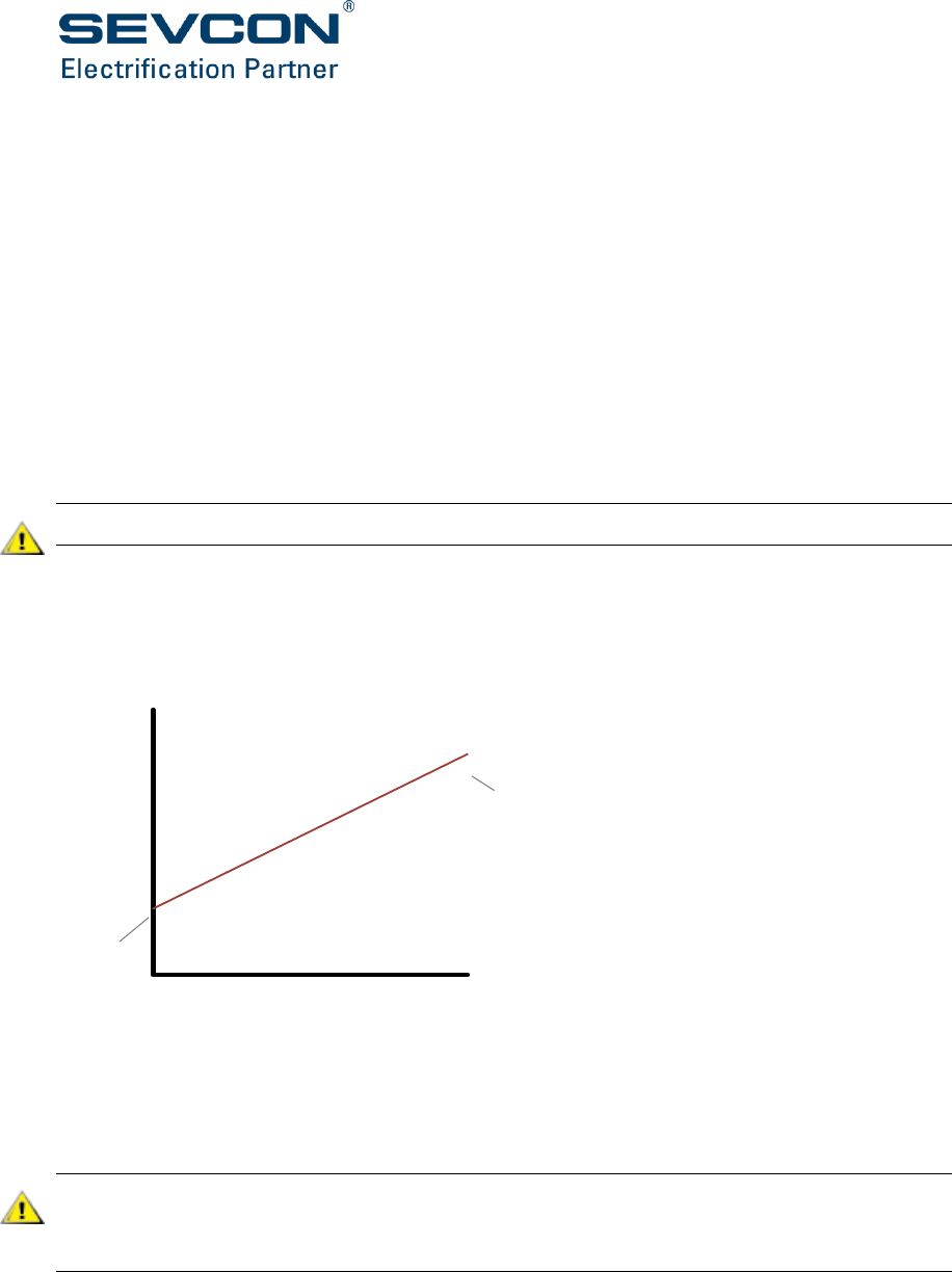
6-22
Dual Throttle Inputs
Single and dual throttle inputs are supported.
Single throttle inputs are normally used with other interlock inputs (eg FS1, deadman, etc) and
use a single input voltage to determine driver demand.
Dual throttle inputs use two separate input voltages, each of which is converted to a throttle
value using 2910h, subindices 3 to 6 (throttle input 1) and subindices 7 to 10 (throttle input 2). If
the throttle values differ by more than 5%, a throttle fault is set and the system will not drive.
To enable dual throttle functionality, map a second analog input to 2224h. The throttle value for
the second throttle input can be read at 2626h.
Dual throttle systems allow a virtual FS1 feature, which can be used instead of an actual FS1
switch. This feature can be enabled on dual throttle systems using 2910h, 1.
The voltage input characteristics of the two analogue throttle inputs must be different.
Creep Torque
Creep torque allows a small amount of torque to be applied as soon as the throttle is closed. This
can be used on some vehicles to overcome the friction required to achieve initial vehicle
movement.
Torque Demand
Throttle value
Creep
torque
Max
torque
Figure 26: Illustration showing behaviour of creep torque
Increasing the creep torque level can improve how the vehicle feels when drive is first selected
and the vehicle starts to move. However, too much creep torque can make the vehicle
uncontrollable at low speeds.
Creep torque will be applied as soon as drive is selected and the throttle is closed. Do not increase
the creep torque value to a level that would cause unexpected high levels of torque output for
comparatively low levels of throttle push. If in doubt, set the creep torque level to 0%.

Configuration
Doc No: 177/52701 6-23
Rev: 3.3
Driveability Features
These features are used to configure how the system uses throttle information and how it handles
speed limits (in torque mode). The installer must ensure these features are configured
appropriately.
Set the following driveability features at 2910h,1:
Enable/disable proportional braking. If enabled, the braking torque during direction
braking is proportional to the throttle.
Enable/disable directional throttle. If configured as a directional throttle, the throttle
voltage indicates the direction as well as the speed demand. This removes the need for
forward and reverse direction switches.
Proportional speed limit enable/disable. If enabled, speed limit is proportional to the
throttle, otherwise speed limit is fixed at the forward or reverse maximum speed. Only
used in torque mode.
Proportional Speed Limit is not recommended for on-highway vehicles as it can cause the traction
motor/wheel to remain locked or brake severely if the wheel is momentarily locked due to loss of
traction on a slippery surface and/or mechanical braking.
Braking directional throttle enable/disable. If enabled, a directional throttle can be used
to demand a drive or braking torque in conjunction with the direction switches. Only
used in torque mode.
Reverse speed limit encoding. Controls how reverse speed limits are handled in torque
mode. Must always be enabled on Slip control systems, and must always be disabled on
flux vector and PMAC systems.
Handbrake fault. If enabled, a handbrake fault is set when a direction is selected whilst
the handbrake input is active.
Proportional speed limit during braking enable/disable. If enabled, speed limit is
proportional to throttle only in drive states. Maximum speed limit is allowed in braking
states. Only used in torque mode.
Driveability Consolidation. Normally, driveability profiles are only used to reduce vehicle
performance, however, if this is enabled, an active driveability profiles over-writes the
baseline. This allows vehicle performance to increase when a profile is active. Note, that
this feature is not available in all software builds.
Allow step change in steering angle. If enabled, steering angle can change instantly with
steering voltage. If disabled, steering angle is rate limited to 90˚/s which prevents sudden
steering angle changes in the event of a steering sensor wire-off.
Virtual FS1 enable/disable. If enabled, this sets up a virtual FS1 feature on systems with
dual throttle inputs configured.

6-24
An s-curve profile can be applied to the speed target (in speed mode) or maximum speed (in
torque mode). This can be set at 290Ah.
Acceleration and braking
See ‘Driveability profiles’ for more information on page 6-26.
Some vehicles can exhibit shock due to the rapid reversal of torque after a direction change.
2909h can be set to force the vehicle to remain stationary for a period before driving in the new
direction.
To prevent early exit from neutral braking, a debounce timer can be set at 290Dh. Neutral braking
only finishes when the vehicle has been stopped for longer than this time. This can help prevent
early exit of neutral braking due to motor oscillation caused by under damped suspension.
On vehicles with gearbox meshing issues, a slower rate of torque ramp up at low speeds can be
configured at 291Ch. This slow rate of change of torque lessens shock due to gear meshing. Used
in torque mode only.
Brake feathering reduces neutral and foot braking torques as the vehicle speed approaches 0 to
prevent any roll-back in the opposite direction. This is set at 290Eh. Used in torque mode only.
Footbrake
The controller can use a switch or analog voltage as the footbrake input. If a footbrake switch is
mapped, it applies maximum foot braking when the switch is closed. The footbrake switch object
(2130h) must be mapped to a digital input.
If the footbrake input is an analog voltage, configure the voltage levels in the same way as the
throttle. The footbrake voltage (2221h) must be mapped to an analog input.
Configure the characteristics of the footbrake at 2911h:
Drive/foot braking priority. If the throttle and footbrake are pressed at the same time,
this setting determines whether the system attempts to drive or brake.
Minimum speed for braking. Foot braking stops when the vehicle speed drops below this
level.
Footbrake voltage input and Input characteristic. These settings are similar to those for
the throttle. Refer to the Throttle section above for more information.
The footbrake value calculated from the voltage can be read at 2621h.
Steering inputs – twin driving motor systems
Loss of steering information can make a vehicle operate erratically. The analog input use for the
steering sensor should have suitable wire-off protection configured.
Twin motor systems, which use the drive motors for turning, require some means of determining
the angle of the steering wheel.
To do this use one of these options:

Configuration
Doc No: 177/52701 6-25
Rev: 3.3
A steering potentiometer to give an analog voltage which is a linear function of the
steering angle. The steer potentiometer voltage (2223h) must be mapped to an analog
input.
Four digital inputs representing ‘inner left’, ‘inner right’, ‘outer left’ and ‘outer right’. The
inner switches indicate the steering angle where torque to the inner wheel motor is
removed. The outer switches indicate the steering angle where inner wheel motor
changes direction. The outer switches are optional. The steer switches (212Bh to 212Eh)
must be mapped to digital inputs.
Steering angle from 3rd party CAN device. This can be received via RPDO on object 2624h
in 0.01 ˚/bit resolution.
To configure steering inputs go to index 2913h in the Object Dictionary:
Setup the voltages corresponding to fully left, fully right and straight ahead. Using this
information, Gen4 Size 8 calculates the steering angle based on the voltage from a
steering potentiometer.
Setup the steering map. This map defines the relationship between the inner and outer
wheel speeds and the steering angle. Each map has 4 user definable points as shown in
Figure 27.
Figure 27: Graph of speed vs. steering angle
The speed and steering angle are normalized. Speed is normalized to maximum vehicle speed
and the steering angle to 90 ˚.
In speed mode, outer wheel speed target and maximum torque is scaled according the outer
wheel map. Inner wheel speed target and maximum torque is scaled to the outer wheel demands
according to the inner wheel map.
-1
-0.8
-0.6
-0.4
-0.2
0
0.2
0.4
0.6
0.8
1
0 0.2 0.4 0.6 0.8 1 1.2
Demand (pu)
Steer angle (pu)
Outer Wheel
Inner Wheel
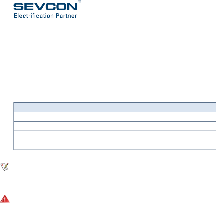
6-26
In torque mode, both inner and outer wheel maximum speeds are scaled according the outer
wheel map. The outer wheel target torque comes from the throttle. The inner wheel target
torque is scaled to the outer wheel actual torque according the inner wheel map.
In object 2913h, 0 to 1 is represented by values in the range 0 to 32767. The inner wheel is scaled
according to the outer wheel. Where a demand (pu) of -1 is shown at 90 ˚ for the inner wheel,
this means the inner wheel demand will be equal and opposite to the outer wheel.
The calculated steering angle can be read at 2623h. An angle value of -32767 indicates full
steering to the left, +32767 full steering to the right and 0 is straight ahead.
If steering switches are used instead of a steering potentiometer, only part of the steering map
is used as shown in Table 6.
Value
Description
2913h,9
Outer wheel speed during inner wheel cutback
2913h,11
Outer wheel speed during inner wheel reversal
2913h,17
Inner wheel cutback speed
2913h,19
Inner wheel reverse speed
Table 6: Objects to set when using steering switches
During a turn the inner wheel speed is slowed by power reduction instead of braking to prevent
the outer wheel motor working against the inner wheel motor.
Driveability profiles
Ensure driveability profiles are disabled when not required. Activation of a driveability profile can
cause driving parameters to change.
Driveability profiles allow you to set maximum values for speed, torque, acceleration and
deceleration for use in a range of operational situations. In addition, in torque mode, there are
ramp rates for speed limits as well. Figure 28 and Figure 29 show the change in speed and torque
target under various driving conditions over a period of time.
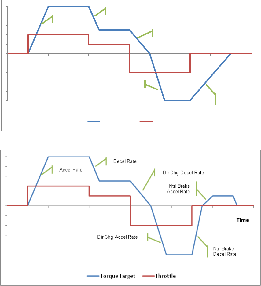
Configuration
Doc No: 177/52701 6-27
Rev: 3.3
Figure 28: Speed mode Acceleration/Deceleration
Figure 29: Torque mode Acceleration/Deceleration
In Torque mode, the acceleration and deceleration rates control the rate of change of torque. In
Speed mode, the acceleration and deceleration rates control the rate of change of speed.
You can select reverse while driving in the forward direction with your foot still on the throttle.
In this situation the controller applies braking in the form of a direction change deceleration rate
down to zero speed. It then applies a direction change acceleration rate to increase the vehicle’s
speed in the reverse direction up to the set maximum speed as shown above.
Configure the following drivability profiles to suit your application (each containing the same set
of parameters):
Time
Speed Target
Throttle
Accel Rate
Decel Rate
Dir Chg Decel Rate
Dir Chg AccelRate
Ntrl Brake
Decel Rate

6-28
Traction baseline profile: the default and highest set of values (2920h).
Drivability select 1 profile: invoked when drivability select 1 switch is active (2921h) or
an alternative trigger is active (see below).
Drivability select 2 profile: invoked when drivability select 2 switch is active (2922h) or
an alternative trigger is active (see below).
The traction baseline profile contains the default maximum values. All of the remaining profiles
apply lower, modifying values to the baseline profile. BDI and service profiles, when configured,
are automatically applied by the software under preset conditions. For example you may want
to limit the acceleration and maximum speed of a vehicle when the battery gets low to maximize
the operating time before recharge. The remaining profiles are applied by the driver with a
switch.
Drivability profiles can also be invoked by internal software triggers, such as BDI low, service
required or low speed. These can be selected to suit specific application requirements. Set the
profile triggers in 2931h.
Where more than one profile is active, the lowest value(s) are used by the software.
Speeds in driveability profiles are scaled according to the vehicle gear ratio (2915h). This is used
to convert speed in RPM to any other preferred unit such as KPH or MPH. To remove this scaling
and leave driveability profile speeds in RPM, set 2915h,3 to 1.
Torques in driveability profiles are in 0.1%/bit resolution. These are converted to Nm using the
motor rated torque value at object 6076h.
Ramp rates in driveability profiles are in either RPM/s for speed mode, or %/s for torque mode.
In speed mode, RPM/s becomes “User Defined Units” / s if the gear ratio is used to rescale the
driveability profile speeds.
Speed limit ramp rates are only used in torque mode and are in RPM/s (or user defined units /
s).
In addition to the speed limit ramp rates in the profiles, 291Eh can be used to configure safety limits
on speed limit ramping. The installer should set these ramp rates to suitable levels to ensure speed
limits cannot ramp faster than could actually happen on a vehicle. This can protect against harsh
braking if traction wheels are momentarily locked.
Preventing Wheel Lock Scenarios
For certain vehicle types, particularly on-highway vehicles or electric motorcycles, the possibility
of wheel locking during drive must be considered.
During braking, the controller will maintain a speed limit to ensure the vehicle does not over
speed if entering braking whilst travelling downhill. If proportional speed limit is set then the
speed limit will follow actual speed toward zero whenever actual speed is dropping rapidly,
usually due to some external influence such as application of mechanical brakes.
If the brakes are applied too harshly, then there is possibility to lock the drive wheels. In these
circumstances, the normal reaction of the driver is to release the brake to allow the wheels to
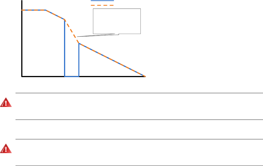
Configuration
Doc No: 177/52701 6-29
Rev: 3.3
rotate again. The correct operation of the controller in this scenario is to allow the wheels to
continue to rotate, and not impose a speed limit.
The maximum rate at which the speed limit can increase or decrease is specified in object 291Eh.
By limiting the rate at which the speed limit can decrease, we can ensure that if the brakes are
released after they had locked the drive wheels, the controller’s speed limit will allow them to
rotate again. The operation of this is shown in Figure 30 below.
Speed
Actual Speed
Speed Limit
Vehicle wheels lock, but rather than
stepping down speed limit, it ramps
down at the maximum speed limit
deceleration rate as specified in
object 291E. When wheels recover,
the motor control will allow them to
rotate again.
Figure 30: Example of behaviour of speed limit when drive wheels are locked
It is important to consider the behaviour of the vehicle under all drive conditions, including when
traction is lost due to locking of the drive wheels. When testing a vehicle, check that the vehicle
behaves in a safe manner when performing harsh braking on low-friction surfaces such as gravel.
Controlled roll-off
Controlled Roll-Off is not recommended for on-highway vehicles as it can cause the traction
motor/wheel to remain locked or brake severely if the wheel is momentarily locked due to loss of
traction on a slippery surface and/or mechanical braking.
Controlled roll-off limits a vehicle to a slow, safe speed if it starts to move without any operator
input. Primarily, it is to prevent uncontrolled movement if a vehicle’s brakes fail on an incline.
Controlled roll-off operates whether the operator is present or not.
Configure the following at object 2930h:
Enable/disable controlled roll-off
Set a roll-off maximum speed
Set a roll-off maximum torque
Alternatively, Gen4 Size 8 can apply an electromagnetic brake if one is mapped and roll-off is
detected. Refer to ‘Electro-mechanical brake’ on page 6-34 for more information.
6-30
Hill hold
Hill Hold is not recommended for on-highway vehicles as it can cause the traction motor/wheel to
remain locked or brake severely if the wheel is momentarily locked due to loss of traction on a
slippery surface and/or mechanical braking.
A vehicle on a hill can be held at a standstill for a configurable time when the operator selects
neutral. At the end of this time or if the seat switch indicates the operator is not present, hill hold
terminates and the vehicle can start to move if parked on an incline. If enabled, the system will
enter controlled roll-off after hill hold.
You can set the hill hold delay at object 2901h. Set the hill hold delay to 0 to disable this feature.
In speed mode, drive torque is disabled whilst neutral braking to stop. However, drive torque
must be re-enabled when entering Hill Hold to allow torque to be applied to hold on the incline.
Set the speed to re-enable drive torque at 2908h.
Inching
Ensure inch switches are only mapped to digital inputs when required. Activation of these inputs
can cause a drive condition to occur.
Inching allows an operator to manoeuvre a vehicle, at low speeds, towards a load. Inching can
be initiated with one switch. A time-out is used to prevent the vehicle from continuing to drive
indefinitely if the switch gets stuck or goes short circuit.
To configure inching:
Ensure forward and reverse inching switches have been mapped to two digital inputs.
Specify an inching speed (0% to 25% of the full speed of the vehicle) at 2905h sub-index
1. This is either a speed target in speed mode, or maximum speed in torque mode.
Specify an inching throttle (0 to 100%) at 2905h sub-index 3. This gives a torque target
in torque mode. This is not used in speed mode.
Specify a time-out (0.1 s to 5.0 s) at 2905h sub-index 2.
Belly Switch
Ensure the belly switch is only mapped to a digital input when required. Activation of this input can
cause a drive condition to occur.
The belly switch is normally connected to the end of the tiller arm on class 3 vehicles. When
activated it forces a drive condition in forward at a user specified throttle value and maximum
speed for a specified time.
To configure belly:
Ensure the belly switch is mapped to a digital input.
Specify the maximum belly speed at 290Ch sub-index 2.

Configuration
Doc No: 177/52701 6-31
Rev: 3.3
Specify a belly throttle at 290Ch sub-index 1. This will determine the torque demand in
torque mode or speed demand in speed mode.
Specify a belly time out at 290Ch sub-index 3. The belly function will cease after this time
has expired.
Drivability select switches
Ensure the driveability switches are only mapped to digital inputs when required. Activation of these
inputs can cause driving parameters to change.
There are two drivability select switches (2126h and 2127h).
To enable either of these they must be mapped to digital inputs. When they are active, the
corresponding drivability profiles (2921h and 2922h) are applied.
See Driveability profiles (page 6-26) for more information.
Economy
The economy input is an analog input which can be used to increase vehicle efficiency and extend
battery life. It is normally controlled using a potentiometer mounted on the vehicle’s dashboard.
The economy voltage (2222h) must be mapped to an analog input.
Efficiency is improved by reducing the acceleration rate or the maximum torque.
Configure the economy input at object 2912h as follows:
Economy function: select acceleration or torque.
Economy voltage input: These settings are similar to those for the throttle
(see page 6-19).
The economy value calculated from the voltage can be read at 2622h.
Pump configuration
The controller can use a mixture of switch and analog voltages as the pump input. In addition,
the power steer function can be used as an extra input to the pump if the pump motor is required
to supply pump and power steering.
Pump motors always run in speed mode. Ensure the motor slave is also configured for speed mode
in 6060h.
General Setup
Configure the pump features at 2A00h:
Inhibit pump when BDI drops below cut-out level. If already operating when the cut-out
occurs, the pump will continue to operate until all pump inputs are inactive.
Drive Enable switch and/or Seat switch input disables pump.

6-32
Ignore Line Contactor state. Allows the pump to operate if it is not connected to the
battery through the line contactor. Should be set if the pump also supplies power
steering and the power steer is required to operate when the line contactor is open.
Use Power Steer target velocity as pump input, if pump also supplies power steering.
Enable minimum pump speed. Enable this to force the pump to run at minimum speed
(2A01h, 2) even when there is no trigger. Can be used to maintain minimum pump
pressure.
Pump to stop on Low Battery. Enable to force pump to stop immediately on low battery
condition.
Use power steer demand to minimum pump speed. Enable this to force the pump to use
power steer demand as a minimum speed. Can be used to maintain minimum pump
pressure for power steering.
Set the pump minimum and maximum speed, maximum torque, acceleration and deceleration
at 2A01h. The pump speed is calculated as the value from the inputs multiplied by the maximum
speed.
Priority/additive inputs
Each pump input can be configured as a priority input or an additive input. When calculating the
pump demand, the controller selects the demand from the highest priority active input, and then
adds the demand from all the active additive inputs.
Configure priority/additive levels in 2A10h and 2A11h, and 2A20h to 2A26h.
Pump throttles
There are 2 pump throttle inputs, which can be configured independently at 2A10h and 2A11h.
The pump throttles allow proportional control of the pump speed.
Configure inputs as priority or additive and set the voltage levels in the same way as the traction
throttle. The pump throttles must be mapped to analog inputs.
Pump switches
There are 7 pump switch inputs. Configure each input as priority or additive and assign it a value
at 2A20h to 2A26h. The pump switches must be mapped to digital inputs.
Pump Driveability Profiles
Pumps have configurable driveability profiles. Profiles are triggered by pump driveability select
switches (2152h and 2153h). One or more of these switches must be mapped to enable pump
profiles.
Each profile allows the installer to reduce acceleration and deceleration rates, throttle and switch
values and maximum torque.
Set pump driveability profiles at 2A30h and 2A31h

Configuration
Doc No: 177/52701 6-33
Rev: 3.3
Power steer configuration
General
Power steering can be provided using:
Contactor. Map the power steer contactor drive object to an analog output.
Pump motor controller. Configure pump to provide power steering. Power steer demand
is added to pump demand.
Dedicated motor controller. Map power steer application motor object to motor control
slave.
Power steer motors always run in speed mode. Ensure the motor slave is also configured for speed
mode in 6060h.
The power steer can be triggered by a number of events:
Vehicle moving
FS1 switch activating
Direction selected.
Seat switch activating
Footbrake activating
The power steering function will always attempt to execute, even if the line contactor is open due
to a fault condition. This is to ensure power steering continues to operate at all times.
Set the power steer motor speed, acceleration and deceleration at 2B01h. This is not required if
the power steer motor is operated by a contactor.
Variable Assist Power Steering
Gen4 Size 8 supports a variable assist power steering algorithm which can be used to reduce the
power steering speed as vehicle traction speed increases to a user configurable level. Set the
reduction factor and traction speed in 2B02h. This allows power steering effort to be reduced as
vehicle speed increases to prevent steering becoming too light.

6-34
Vehicle features and functions
Ensure you have completed the CANopen network setup, Motor Characterization, I/O
Configuration and Vehicle Performance Configuration processes described above.
Contactors
Ensure voltage control has been selected (see ‘Analog (contactor) outputs’ on
page 6-15).
To configure any contactor:
Set pull-in voltage, pull-in time and hold-in voltage at 2D00h
Enable each output to operate at the pull-in voltage or at the maximum voltage at 2D01h
If required enable each output to reduce to the hold voltage level at 2D02h
Line contactor
Gen4 Size 8 does not support line contactor or precharge functionality. An external device must
be used to isolate the Gen4 Size 8 from the vehicle battery. This external device is also
responsible for any capacitor precharging required to prevent damage to the line contactor tips.
Electro-mechanical brake
Electro-mechanical brakes are not recommended for on-highway vehicles as they can cause the
traction motor/wheel to remain locked or brake severely if the wheel is momentarily locked due to
loss of traction on a slippery surface and/or mechanical braking. Also, electro-mechanical brakes
normally fail to the applied state, meaning any loss of power, or wiring fault can cause the brakes
to be applied.
The electro-mechanical brake object (2420h) must be mapped to an analog output.
Set the conditions under which it is applied at 2903h.
The brake can be applied when the vehicle stops or when roll-off is detected. If the brake is
configured to apply when the vehicle stops, it is not applied until the vehicle has been stationary
for more than the brake delay time.
To prevent vehicle roll away on inclines, the electro-mechanical brake normally does not release
until the traction motor(s) are producing torque. This feature can be disabled using 2903h,3.
External LED
This mirrors the operation of the controller’s on board diagnostic LED. The external LED object
2401h can be mapped to an analog output to drive a lamp on a vehicle dashboard.
Alarm buzzer
The alarm buzzer object (2402h) must be mapped to an analog output.
Configuration
Doc No: 177/52701 6-35
Rev: 3.3
Configure the alarm buzzer output, if required, to be activated by one or more of these conditions
at 2840h:
forward motion or forward direction selected
reverse motion or reverse direction selected
faults other than information faults
controlled roll-off
BDI low.
A different cadence for each of the above conditions can be configured.
Brake Lights
A brake light output object is available (2404h) and can be mapped to an analog output. The
brake lights will illuminate whenever the footbrake is pressed (providing either an analog or
digital footbrake input is available) or the system is in direction change braking.
Horn
Ensure a digital input switch is mapped to the horn switch object (2101h) and an analog output
is mapped to the horn object (2403h).
Service indication
The controller can reduce vehicle performance and indicate to the operator when a vehicle
service is required. The interval between services is user-configurable.
Configure the following at object 2850h:
Service indication: via an analog (contactor) output (e.g. to drive a dashboard lamp)
and/or Gen4 Size 8’s LED.
Source hours counter: selects the hours counter and is used to determine when a service
is required.
Service interval: hours between vehicle services. Can be used by the reset function (see
below) or for information only.
Next service due: Servicing is required when the source-hours counter reaches this time.
This can be set manually, or automatically using the reset function; see below.
Reset function: write to the reset sub-index at 2850h to automatically reset the service
timer for the next service. The next service due time is calculated as the source hours
counter time plus the service interval.
Service profile
This is a drivability profile where you can set maximum torques, speeds and acceleration rates
to be applied when a vehicle needs servicing (2925h). See ‘Driveability profiles’ on page 6-26.
6-36
Traction motor cooling fan
This object can be used to drive a motor cooling fan when the operator is present on the vehicle
(as indicated by the seat switch). The cooling fan object (2421h) must be mapped to an analog
output.
Controller heatsink fan
A controller offers the option of heatsink fans to cool the heatsink instead of liquid cooling.
The temperature at which the heatsink fans turn on and off are configurable. The fans will be
turned on by the controller when the heatsink temperature exceeds a specified temperature.
The fans turn off when the temperature is cold. The temperatures at which the fans turn on and
off, is programmed using the internal heatsink fan object (5A02h).
The temperature set-point to turn on the fans should be higher than the set-point to turn off the
fans
The heatsink fans can be configured in 5A02h to output a warning fault if the fans stop rotating.
Controller external heatsink /motor cooling fan
An external fan to cool the controller heatsink or a motor may be connected to one of the
analogue outputs. The fan will be turned on by the controller when either the heatsink
temperature or the motor temperature exceed a specified temperature. The fan turns off when
the nominated temperature is cold. The temperatures at which the fans should turn on and off,
the analogue output to use for the fan, the fan voltage and the temperature source (heatsink or
motor) can be programmed using the external heatsink fan object (5A01h). Note that the
contactor driver outputs may be damaged if connected to capacitive loads. It is quite common
for fans to incorporate capacitive elements, in which case a relay should be used to isolate the
fan from the contactor driver output.
The temperature set-point to turn on the fans should be higher than the set-point to turn off the
fans
The fans will not operate if another function is configured to run on the specified analogue output.
Motor over-temperature protection
The controller protects motors from over-temperature. It maintains a motor temperature
estimate and can also accept a direct temperature measurement via an analog input (for a
thermistor) or a digital input (for an over-temperature switch).
The temperature estimate is calculated by monitoring current to the motor over time. The
estimate is configured at 4621h.
The estimate is always applied, since it can detect increases in motor temperature more quickly
than the direct measurement. Direct measurement is normally done on the motor casing, which
lags behind the internal temperature.

Configuration
Doc No: 177/52701 6-37
Rev: 3.3
Motor over-speed protection
A facility to protect the motor or vehicle power train due to damage by over speeding is available
on the controller. A maximum speed can be configured at object 4624h. Under normal operation
the controller should output braking torque to prevent the over speeding initially, if the
measured speed exceeds this limit then the controller will shut down and a fault will be set.
The trip speed offers a final level of protection for the vehicle mechanics, and should be set to a
level that would not be expected to be reached under normal operation.
Battery protection
The nominal battery voltage must be set at 2C00h.
Over voltage
Battery over voltage usually occurs during regenerative braking.
To provide protection set values for these parameters at 2C01h:
Over voltage start cutback: the value at which the braking effort is linearly reduced to
limit voltage increase.
Over voltage limit: the value at which the controller cuts out. A fault is set if the voltage
exceeds the cut-out voltage.
Under voltage
To prevent excessive battery discharge, set values for these parameters at 2C02h:
Under voltage start cutback: the value at which the current drawn from the battery is
reduced to limit voltage decrease.
Under voltage limit: the value at which the controller cuts out. A fault is set if the voltage
drops below the cut-out voltage for longer than the protection delay
Protection delay: the time it takes for the controller to cut-out after the under voltage
limit has been reached (2C03h).
Battery Discharge Indicator (BDI)
CAUTION: When not in use ensure the BDI function is disabled by setting the Cell Count (in 2C30h,
6) to 0.
Monitor battery voltage using Gen4 Size 8’s Battery Discharge Indicator (BDI). The BDI presents
the driver with a percentage remaining charge figure and has become an industry standard in
recent years.
The BDI is not a measure of the absolute battery charge remaining and therefore we recommend
you regularly check the absolute value in accordance with the battery manufacturer’s
instructions.
To use the BDI, configure the following parameters at 2C30h in the Object Dictionary:

6-38
Cell count: this is the number of battery cells and is normally half the battery voltage, as
cells are usually 2 volts each.
Reset voltage (V): set this to the cell voltage when the batteries have just been charged.
This resets the BDI back to 100%.
Discharge voltage (V): set this to the cell voltage when the battery is discharged.
Cut-out level (%): this is the level at which the vehicle adopts the low battery drivability
profile.
Discharge rate (s/%): this is the rate at which the BDI remaining charge value discharges.
Set to 0 to use default value of 16.8s to reduce by 1%. This default should suit most lead-
acid battery types, however, this can be increased/decreased for different battery
technologies.
Setting the warning and cut-out levels to 0% disables the warning and cut-out functionality
Read the percentage remaining charge value from 2790h sub-index 1 in the Object Dictionary.
Battery Current Limit
Battery current can be limited by the controller for the purposes of efficiency or to protect
batteries that are sensitive to high levels of current flow. Charge and discharge currents can be
limited independently.
If limiting the discharge current flow, this can extend the time taken for the vehicle to reach top
speed. Note that limiting the charge current flow back to the battery can impede the
performance of regenerative braking.
Compatibility with some CAN based battery management systems is provided. It is also possible
to configure different discharge limits for each driveability profile. The behaviour of battery
current limit can be configured using object 2870h. Object 4623h shows the current limits that
are in effect, and allows you to specify the cutback aggressiveness and a measurement correction
factor. Battery current flow can be monitored at object 5100h.
Note that regen currents flowing back to the battery are specified as negative numbers.
Displays
Gen4 Size 8 is compatible with the Smartview and Clearview displays.
Clearview displays use the CANopen protocol. To use, set up TPDOs to transmit the required data
for the display.
Smartview displays use Sevcon’s proprietary CAN protocol. To use set the CAN baud rate to
100kHz at 5900h, enable Smartview and select hours counter at 2E00h.

1
CHAPTER 7:
MONITORING GEN4
SIZE 8

A-2
Reading status variables
All status variables are in Gen4 Size 8’s object dictionary. They can be accessed using SDOs. Some
can be mapped to PDOs for continuous transmission to remote nodes such as displays and
logging devices.
Motor measurements
The following status objects can be read:
Motor slip frequency, currents, voltages and temperature at object 4600h.
Additional motor debug information is available at 4602h.
Motor torque, speed, etc. at objects 6000h to 67FFh.
Heatsink temperature
Read the heatsink temperature at object 5100h, sub-index 3.
Identification and version
Read identification and version information at:
1008h – Controller name.
1009h – Hardware version.
100Ah – Software version.
1018h – Identity object. Contains CANopen vendor ID, product code, CANopen protocol
revision, and controller serial number.
5500h – NVM (EEPROM) format.
5501h – Internal ROM checksum.
Battery monitoring
The controller measures actual battery voltage at two points:
Battery voltage; measured at keyswitch input and read at 5100h sub-index 1.
Capacitor voltage; measured at the B+ terminal and read at 5100h sub-index 2.
The controller also has a battery discharge indicator (BDI), which can be read at 2790h.

Configuration
Doc No: 177/52701 A-3
Rev: 3.3
Hours counters
The controller supports many different hours counters for various functions. Some counters run
on all units and some only run on the Gen4 Size 8 configured as the vehicle master.
Hours counters are preserved with a minimum resolution of 15 seconds when the system is
powered down.
Local hours counters
Local hours counters which run on all units are:
Controller key hours: increments while the keyswitch is in the ON position (5200h).
Controller pulsing hours: increments when the controller is powering its connected
motor (4601h).
Vehicle hours counters
Vehicle hours counters which run only on the Gen4 Size 8 configured as the vehicle master are:
Vehicle key hours: increments as controller key hours (2781h).
Vehicle traction hours: increments when the vehicle is driving or braking (2782h).
Vehicle pump hours: increments when the pump motor is running (2783h).
Vehicle power steer hours: increments when the power steer motor is running (2784h).
Vehicle work hours: increments when the traction, pump or power steer motors are
running (2785h).
Since these hours are specific to the vehicle, they are writeable so that they can be reset to
known good values if the master controller is replaced.
Logging
The controller can log events in the system (along with additional event-related information) and
minimum and maximum levels of important parameters. You need different levels of access to
clear the contents of the logs.
Logs are normally reset individually. However, to reset all logs at once write to 4000h.
FIFO event logs
Events are recorded by these two separate FIFOs (first in, first out logs), which operate
identically:
System: this FIFO is 20 elements deep and is used for events such as software upgrades,
user logins and some hardware upgrades (4100h to 4102h).
Faults: this FIFO is 40 elements deep and is used for fault logging (4110h to 4112h).

A-4
At object 41X0h:
Reset the FIFO
Read its length
You can access the FIFO using objects 41X1h and 41X2h. The FIFO index is entered at 41X1h and
the data is read from 41X2h.
Event counters
The controller provides 10 event counters at 4200h to 420Ah. Each event counter can record
information about occurrences of one event. The allocation of event counters to events is user-
configurable however Gen4 Size 8 will automatically count important events in unused counters.
The information recorded in each event counter is:
The time of the first occurrence
The time of the most recent occurrence
The number of occurrences
Operational monitoring
At objects 4300h and 4301h, Gen4 Size 8 monitors and records the minimum and maximum values
of these quantities:
Battery voltage
Capacitor voltage
Motor current
Motor speed
Controller temperature
Two instances of the operational monitoring log are maintained. Service engineers can access
and clear the first log; the second is accessible and clearable only by Sevcon engineers. The
Customer copy is normally recorded and reset each time the vehicle is serviced. The Sevcon copy
records data over the controller’s entire working life.
CANopen abort code
The controller will sometimes respond with a CANopen General Abort Error (08000000h) when
the object dictionary is accessed. This can occur for many reasons. Object 5310h gives the exact
abort reason. These are:

Configuration
Doc No: 177/52701 A-5
Rev: 3.3
0
None
12
Invalid value
24
Cannot read from DSP
1
General
13
EEPROM write failed
25
Peek time out
2
Nothing to transmit
14
Unable to reset service
time
26
Reserved for future use
3
Invalid service
15
Cannot reset log
27
Reserved for future use
4
Not in pre-operational
16
Cannot read log
28
Reserved for future use
5
Not in operational
17
Invalid store command
29
Reserved for future use
6
Cannot go to
pre-operational
18
Bootloader failure
30
Reserved for future use
7
Cannot go to
operational
19
DSP update failed
31
Reserved for future use
8
Access level too low
20
GIO module error failed
32
Checksum calculation
failed
9
Login failed
21
Backdoor write failed
33
PDO not copied
10
Range underflow
22
Reserved for future use
11
Range overflow
23
Cannot write to DSP

A-6
Faults and warnings
Introduction
In the event of a fault Gen4 Size 8 takes the following action:
Protects the operator and vehicle where possible (e.g. inhibits drive).
Sends out an EMCY message on the CANbus.
Flashes the LED in a pattern determined by the fault type and severity.
Logs the fault for later retrieval.
Fault identification
You can identify a fault as follows:
Check the number of LED flashes and use below to determine what action can be taken.
A complete and comprehensive fault identification table will be available from Sevcon in
due course.
Pick up the EMCY on the CANbus and read the fault condition using configuration
software
Interrogate the fault on the node directly using DVT or other configuration software.
LED flashes
Use below to determine the type of fault from the number of LED flashes. The LED flashes a
preset number of times in repetitive sequence (e.g. 3 flashes – off – 3 flashes – off – and so on).
Only the faulty node in a multi-node system flashes its LED. Possible operator action is listed in
the right hand column of the table.
LED
flashes
Fault
Level
Set conditions
Operator action
0 (off)
Internal hardware
failure
RTB
Hardware circuitry not
operating.
1
Configuration item
out of range
VS
At least one configuration
items is outside its allowable
range.
Set configuration
item to be in range.
Use 5621h to
identify out of range
object.
1
Corrupt
configuration data
VS
Configuration data has been
corrupted.
1
Hardware
incompatible with
software or invalid
calibration data
VS
Software version is
incompatible with hardware.
Calibration data for sensors
invalid.

Configuration
Doc No: 177/52701 A-7
Rev: 3.3
LED
flashes
Fault
Level
Set conditions
Operator action
2
Handbrake fault
I
Direction selected with
handbrake switch active.
Release handbrake
2
Sequence fault
DI
Any drive switch active at
power up.
Reset drive switches
2
SRO fault
DI
FS1 active for user
configurable delay without a
direction selected.
Deselect FS1 and
select drive
2
FS1 recycle
DI
FS1 active after a direction
change
Reset FS1
2
Seat fault
DI
Valid direction selected with
operator not seated or
operator is not seated for a
user configurable time in
drive.
Must be seated with
switches inactive
2
Belly fault
DI
Set after belly function has
activated.
2
Inch sequence fault
DI
Inch switch active along with
any drive switch active
(excluding inch switches), seat
switch indicating operator
present or handbrake switch
active.
2
Invalid inch
switches
DI
Inch forward and inch reverse
switches active
simultaneously.
Both inch switches
inactive.
2
Two direction fault
DI
Both the forward and reverse
switches have been active
simultaneously for greater
than 200 ms.
Reset switches
2
Invalid steer switch
states
VS
Steering switches are in an
invalid state, for example,
both outer switches are
active.
Check steer
switches.
3
Fault in electronic
power switching
circuit
VS
Fault in electronic power
switching circuit (e.g. MOSFET
s/c).

A-8
LED
flashes
Fault
Level
Set conditions
Operator action
3
Hardware over
voltage activated
VS
Hardware over voltage circuit
activated
Investigate and
reduce battery
voltage below user
defined maximum
level. Ensure
suitable over
voltage is
configured in 2C01h
and 4612h.
3
Hardware over
current trip
activated
VS
Hardware over current circuit
activated
Check motor load
and wiring. Check
motor parameters
are correct.
4
Line contactor
welded
S
Line contactor closed at
power up or after coil is de-
energized.
Check line contactor
condition/wiring.
4
Line contactor did
not close
S
Line contactor did not close
when coil is energized.
Check line contactor
condition/wiring.
5
PST fault
DI
Fault detected on PST power
steer module.
Check PST
condition.
5
Motor open circuit
S
Unable to establish current in
motor.
Check motor
condition/wiring.
5
Pulsed Enable
Signal
W
Set to indicate pulsed enable
signal is not detected
Check pulsed
enable signal
wiring, check pulse
is present.
6
Throttle pressed at
power up
DI
Throttle demand is greater
than 20% at power up.
Reduce demand
6
Analog input wire-
off
VS
Analog input voltage is
outside allowable range.
Check analog input
wiring
6
Analog output fault
(over/under
current, failsafe,
short circuit driver)
VS
Analog output fault caused by
over current (>4A), under
current if actual current < 50%
target (current mode only),
failsafe circuit fault, short
circuit driver MOSFET.
Check analog
output wiring.
7
BDI warning or cut-
out
I
BDI remaining charge is less
than warning or cut-out levels.
Charge battery.

Configuration
Doc No: 177/52701 A-9
Rev: 3.3
LED
flashes
Fault
Level
Set conditions
Operator action
7
Battery low voltage
protection
I
Battery voltage or capacitor
voltage is below a user
definable minimum battery
level for a user definable time.
Increase battery
voltage above user
defined level
7
Controller low
voltage protection
I
Battery voltage or capacitor
voltage is below the minimum
level allowed for the
controller.
Increase battery
voltage above
minimum level
7
Controller high
voltage protection
with line contactor
closed.
I
Battery voltage or capacitor
voltage is above the maximum
level allowed for the
controller with line contactor
closed.
Investigate and
reduce battery
voltage below
maximum level.
7
Battery high voltage
protection
I
Battery voltage or capacitor
voltage is above a user
definable maximum battery
level for a user definable time.
Investigate and
reduce battery
voltage below user
defined maximum
level.
7
Motor low voltage
protection
I
Capacitor voltage has entered
the motor low voltage cutback
region defined in 4612h.
Increase battery
voltage above start
of motor low
voltage cutback
region.
7
Motor high voltage
protection
I
Capacitor voltage has entered
the motor high voltage
cutback region defined in
4612h.
Reduce battery
voltage below start
of motor high
voltage cutback
region.
7
Controller high
voltage protection
with line contactor
open.
S
Battery voltage or capacitor
voltage is above the maximum
level allowed for the
controller with line contactor
open.
Isolate controller
and investigate high
battery voltage
7
Battery voltage
below critical level
for controller.
S
Battery voltage is below the
absolute minimum voltage at
which the controller hardware
is guaranteed to operate.
Increase battery
voltage.

A-10
LED
flashes
Fault
Level
Set conditions
Operator action
7
Precharge failure
VS
Capacitor voltage is less than
5V after pre-charge operation
is complete.
Check controller
wiring to ensure
there are no short
circuits between B+
and B-.
8
Controller too hot
I
Controller has reduced power
to motor(s) below maximum
specified by user settings due
to controller over
temperature.
Remove loading to
allow controller to
cool down.
8
Controller too cold
I
Controller has reduced power
to motor(s) below maximum
specified by user settings due
to controller under
temperature.
Allow controller to
warm up to normal
operating
temperature.
8
Motor over
temperature
I
Controller has reduced power
to motor(s) below maximum
specified by user settings due
to motor over temperature.
Reduce load to
motor to allow it to
cool down.
8
Motor too cold
I
Motor thermistor reports less
than -30 ˚C
Allow motor to
warm up. Check
motor thermistor.
8
Heatsink over
temperature
VS
Heatsink temperature
measurement has exceed
absolute maximum for
controller and system has
powered down.
Remove loading to
allow controller to
cool down.
10
Pre-Operational
I
Controller is in pre-
operational state.
Use DVT to put
controller into
operational state.
10
I/O initializing
I
Controller has not received all
configured RPDOs within 5s of
power up.
Check CANbus
wiring and PDO
configuration.
10
RPDO Timeout
I / DI
/ S
One or more RPDOs have not
been received within 3s at
power up or within 500ms
during operation.
Check CANbus
wiring and PDO
configuration.

Configuration
Doc No: 177/52701 A-11
Rev: 3.3
LED
flashes
Fault
Level
Set conditions
Operator action
11
Encoder fault
VS
Speed measurement input
wire-off is detected.
Check encoder
wiring
11
Over current
VS
Software has detected an over
current condition
Check motor load
and wiring. Check
motor parameters
are correct.
11
Current Control
fault
VS
Software is unable to control
currents on PMAC motor.
Check motor load
and wiring. Check
motor parameters
are correct.
12
Communication
error
S
Unrecoverable network
communication error has
been detected.
Check CANbus
wiring and
CANopen
configuration.
13
Internal software
fault
RTB
Software run time error
captured
13
Current sensor
auto-zero fault
RTB
Current sensor voltage out of
range with no current.
13
DSP parameter
error
RTB
Motor parameter written to
while motor control is
operational.
Recycle keyswitch
to allow parameters
to be reloaded
correctly.
14
3rd Party
Anonymous Node
EMCY received
I / DS
/ RTB
3rd party node has transmitted
an EMCY message.
Check CANbus
wiring and 3rd party
node status.
15
Vehicle service
required
I
Vehicle service interval has
expired.
Service vehicle and
reset service hours.
Table 7: Fault identification
Fault list
Use DVT to access the Fault list. If you don’t have DVT you can use any configuration tool as
follows:
Object 5300h gives information about all active faults. Read sub-index 1 to get the
number of active faults. Write to sub-index 2 to select one of the active faults (0 = highest
priority) and read back sub-index 3 to read the fault ID at that index.
Object 5610h can be used to read a text description of the fault. Write the fault ID to
sub-index 1 and read back the fault description from sub-index 2.

A-12
Upgrading the controller software
It is possible to field update the firmware of the Gen4 Size 8 controller , typically using Sevcon’s
DVT configuration tool.
Please contact Sevcon for assistance with this process.
