Intermatic Et8215c
User Manual: Intermatic-et8215c
Open the PDF directly: View PDF ![]() .
.
Page Count: 4

®
Electronic Astronomic 7-Day
Time Switches
With Battery Carryover
OWNER/INSTALLER INSTRUCTION MANUAL
ATTENTION: READ CAREFULLY BEFORE ATTEMPTING TO INSTALL YOUR INTERMATIC TIME
SWITCH. FAILURE TO COMPLY WITH INSTRUCTIONS COULD RESULT IN PERSONAL INJURY
AND/OR PROPERTY DAMAGE! RETAIN FOR FUTURE REFERENCE.
Specifications
TIME SWITCH INPUT VOLTAGE:
120/208/240/277 V.A.C., 50/60 Hz.
POWER CONSUMPTION: 6.0 Watts Max.
CONTACT CONFIGURATION: SPST model ET8015C, DPST
model ET8215C, and SPDT model ET8115C
SWITCH RATINGS: ET8015C & ET8215C (Per Pole)
•30 A Inductive/Resistive, 24/120/208/240/277 VAC, 60 Hz.
•20 A Ballast 120-277 VAC 60 Hz.
•20 A Resistive - 28 V DC
• 5 A Tungsten 120/240 VAC 60 Hz.
• 1 H.P.120 VAC 60 Hz.
• 2 H.P. 240 VAC 60 Hz.
SWITCH RATINGS: ET8115C (NO/NC) normally closed contact
•20A/ 10A Inductive/Resistive, 120/208/240/277 VAC, 60 Hz.
•20A/ 10A Resistive - 28 VDC
•6A/ 3A Ballast 120-277 VAC 60 Hz.
• 1 H.P./ 1/4 H.P.120 VAC 60 Hz.
• 2 H.P./ 1/2 H.P. 240 VAC 60 Hz.
•5A/ 3A, 120/240 VAC Tungsten
SET POINTS (EVENTS): 56 total (14 ON & 14 OFF plus 14
Astro ON & 14 Astro OFF). These set points can be
programmed for any or all 7 days to provide for up to 224 set
points each week.
BATTERY POWERED CLOCK OPERATION: 2Years minimum
(Two AAA industrial grade alkaline supplied with time switch)
MIN. “ON” or “OFF” TIME: 1minute.
MAX. “ON” or “OFF” TIME: 6days 23 hours 59 minutes.
SHIPPING WEIGHT:2.5 Lbs. (1.1 Kg)
CASE: NEMA 1 drawn steel; 7-3/4” (19.7 cm) high, 5” (12.7 cm)
wide, 3” (7.6 cm) deep; gray finish w/lockable spring hasp.
KNOCKOUTS: Combination 1/2 - 3/4” (one on back and each
side, two on bottom).
WIRE SIZE: AWG #10 through #18.
General Safety Information
WARNING: Disconnect all power before installing or servicing
this time switch or its connected loads.
1. Follow all local electrical and safety codes, National Electric
Code (NEC), as well as Occupational Safety and Health Act
(OSHA).
2. If the power disconnect point is out of sight, lock it in the “OFF”
position and tag it to prevent unexpected application of power.
3. This time switch case must be grounded.
4. Do not exceed the maximum current carrying capacity of this
time switch.
5. Always replace the plastic insulator covering the terminal
before turning power “ON”.
ET8000 SERIES
http://waterheatertimer.org/How-to-wire-Intermatic-ET-series-timer.html
Description
The Intermatic Electronic Astronomic 7-Day Time Switch automatically
switches loads according to a preset weekly schedule with up-to-the-
minute accuracy. The astronomic feature provides sunset On and sunrise
Off settings to eliminate the need for separate photo control devices. The
independent 7-day programming provides complete flexibility for
applications where load switching differs each day of the week. Astronomic
programming can be combined with independent programs to provide a
sunset On and time Off program.
For use as a on/off timer in applications requiring 7-day astronomic load
control such as lighting, heating, air conditioning systems, pumps, etc. Up
to56 (14 ON & 14 OFF plus 14 Astro ON & 14 Astro OFF) set points
(EVENTS) can be preset. These set points can be programmed for any or
all 7 days to provide for up to 224 set points each week. The program can
be overridden by pushing the ON/OFF load override button(s).This time
switch is designed to directly switch tungsten or ballast loads up to the time
switch rating and inductive or resistive loads up to 30 amps at 120, 208,
240, or 277 volts.
Installation
WARNING: DISCONNECT THE POWER TO THE TIME SWITCH AND
THE LOADS BEFORE INSTALLING THIS TIME SWITCH.
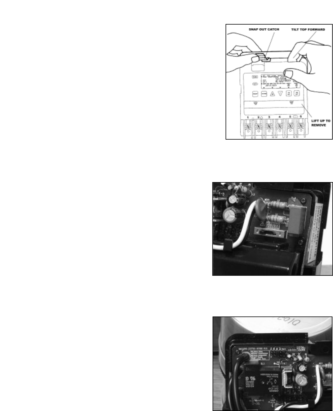
1. Remove the mechanism from the case by depressing the catch at the
top of the case and pulling out. (See Figure #1) The timer is shipped set
for 120VAC operation by means of a selector switch. To operate timer at
208, 240 or 277 VAC, move the selector switch to the appropriate setting,
as marked on the circuit board (See Figure #2). The timer is shipped with
Daylight Savings Time (DST) enabled. To disable this feature insert a
jumper at location marked DST. The ET8215C timer is shipped with the
loads set to be independently controlled (IND), the outputs can be
changed to simultaneous or pulsed operation by moving the jumper to SIM
or PUL respectively. (See Figure #3 and wiring diagrams.)
CAUTION: DO NOT TOUCH THE CIRCUIT BOARD COMPONENTS
SINCE STATIC DISCHARGE COULD DAMAGE THE MICROPROCES-
SOR.
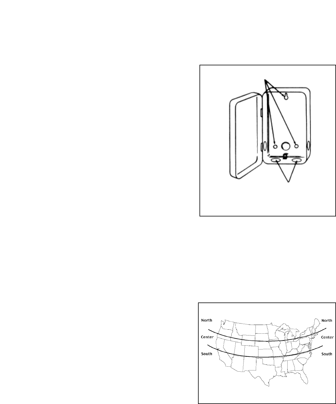
2. Mount the time switch in the desired location using the three mounting
holes that are provided. Mount the time switch at eye level, if possible,
providing sufficient room to the left of the enclosure for the cover to swing
open fully. (See Figure #4)
3. Replace the mechanism in the case.
4. Lift the left side of the insulator off of the retaining post and pivot it up
and away to expose the terminal strip.
5. Strip the supply and load wires by removing 1/2 inch of insulation. DO
NOT USE ALUMINUM WIRE. (See Wiring Diagrams). Insert the wire ends
under the proper terminal plates and tighten the screws firmly. Use AWG
#10 through #18. Connect ground wire to grounding terminal at bottom of
case.
6. Replace the plastic insulator.
7. Be sure that the batteries are functioning properly. This can be checked
by making sure the display is visible. If the display has scrambled
information, press the [RESET] switch. Note that the batteries can easily
be replaced without removing the time switch mechanism or field wiring.
Simply press in and downward (in the direction of the arrows) on the
battery cover.It is recommended that the batteries be replaced with two
“AAA” industrial grade alkaline cells at two to three year intervals as part
of the normal time switch maintenance observing battery polarity markings
when installing. No other maintenance is required.
8. Apply power to the time switch.
9. While pressing and holding the [ENTER] button press the [RESET]
button. The display will now be flashing 12:00 A.M. and MON and is in the
Manual mode. The time switch is now ready for programming.
FIgure 1
FIgure 2
FIgure 3
Programming Steps
By pressing the [MODE] button the time switch will cycle through the
menus necessary for programming the current date, time, astro zone,
astro events, and timed events.
Note: The Date and Time must be entered before any other menus
will become available for programming.
MANUAL MODE
Press the [MODE] button repeatedly until MANUAL appears in the upper
portion of the display. While in this mode the time switch does not follow
any programmed settings, but can be forced on using the [ON/OFF] load
button(s).
DATE set
Press the [MODE] button repeatedly until SET DATE appears in the upper
portion of the display. Enter the current date using the [r], [s], and
[ENTER] keys.
TIME set
Press the [MODE] button repeatedly until SET CLOCK appears in the
upper portion of the display. Enter the current time using the [r]and [s]
keys. Press [MODE] to advance.
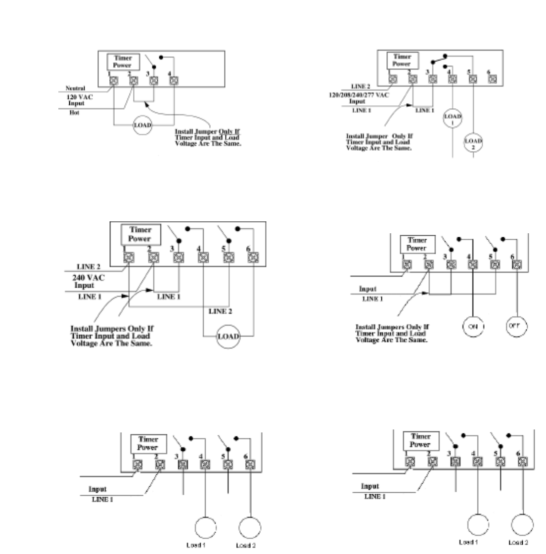
ASTRO ZONE set
Press the [MODE] button repeatedly until SET ASTRO ZONE appears in
the upper portion of the display. Select the proper astro zone using [r]and
[s]keys (See Figure #5). Press [Mode] to advance.
Note: For multi-circuit clocks there are multiple Sunup and Sunset
times allowing the user to use different offsets for the different loads
if desired.
SUNUP set
Press the [MODE] button repeatedly until SET SUNUP appears in the
upper portion of the display. Set the sunup time(s) using [r]and [s]keys,
the morning sunrise is automatically calculated by the timer. This time
setting can be manually adjusted up to 2 hours (120 minutes) in either
direction. Simply consult your local newspaper or weather report to
determine the precise sunrise time in your area. Press [MODE] to
advance.
SUNSET set
Press the [MODE] button repeatedly until SET SUNSET appears in the
upper portion of the display.Set the sunset time(s) using [r]and [s]keys,
the evening sunset is automatically calculated by the timer. This time
setting can be manually adjusted up to 2 hours (120 minutes) in either
direction. Simply consult your local newspaper or weather report to
determine the precise sunset time in your area. Press [MODE] to advance.
Note: For multi-circuit clocks there are Astro On and Astro Off events
for each circuit.
ASTRO EVENTS set
Press the [MODE] button repeatedly until SET ASTRO appears in the
upper portion of the display.Set astro on events. To begin press the [DAY]
button, the display will change to show SUNSET with all days active.
Pressing the [DAY] button cycles through different day selections. To
remove / add single day selections press [r]and [s]at the same time
while the cursor is over the desired day. To disable an event select --:-- --
(nil). Press [ENTER] to set next Astro event or Press [MODE] to advance
to set Fixed event times.
FIXED EVENTS set
Press the [MODE] button repeatedly until SET FIXED appears in the upper
portion of the display.Set fixed event time(s). To begin press the [DAY]
button, the display will change to show 12:00 with all days active, load(s)
and ON@ showing. This is an On event. Pressing the [DAY] button cycles
through different day selections. Pressing the [ON/OFF] load button(s) will
toggle the load(s) in or out of the event. To disable an event select --:-- --
(nil). To clear an event, press [r]and [s]at the same time. Press
[ENTER] to set next event up to 28 events or Press [MODE] to advance to
the Auto run mode.
AUTO Mode
Press the [MODE] button repeatedly until AUTO appears in the upper
portion of the display. While in the Auto mode the time switch will follow the
program that has been defined in the Astro events and Fixed events
menus, however the time switch can still be forced on using the [ON/OFF]
load button(s).
NOTE: Events can be edited or reviewed by returning to the
appropriate menu using the [MODE] button.
FIgure 4
FIgure 5
WIRING DIAGRAMS:
ET8015 configured for SPST 120VAC load. ET8115 configured for SPDT load switching.
ET8215 configured for 240VAC DPST
load with circuit board jumper set to SIM. ET8215 configured for pulse SPST load
with circuit board jumper set to PUL.
ET8215 configured for two SPST loads with
circuit board jumper set to IND. ET8215 configured for DPST loads with cir-
cuit board jumper set to SIM.
LIMITED ONE YEAR WARRANTY
If within one (1) year from date of purchase, this product fails due to a defect in material or workmanship, Intermatic Incorporated will repair or replace, at its
sole option, the unit free of charge. This warranty applies only to the original purchaser and is not transferable. The warranty does not apply to: (a) damage
caused by accident, abuse, mishandling, dropping, acts of God, or any negligent use; (b) units which have been subject to unauthorized repair, opened, taken
apart, or otherwise modified; (c) units not used in accordance with directions; (d) damages exceeding the cost of the product. Some states do not allow a
limitation of damages, so the foregoing limitation may not apply to you. This warranty gives you specific legal rights and you may have other rights that vary
from state to state. INTERMATIC INCORPORATED WILL NOT BE LIABLE FOR INCIDENTAL OR CONSEQUENTIAL DAMAGES. THIS WARRANTY IS IN
LIEU OF ALL OTHER EXPRESS OR IMPLIED WARRANTIES. ALL IMPLIED WARRANTIES, INCLUDING THE WARRANTY OF MERCHANTABILITY AND
THE WARRANTY OF FITNESS FOR A PARTICULAR PURPOSE, ARE HEREBY MODIFIED TO EXIST ONLY AS CONTAINED IN THIS LIMITED
WARRANTY, AND SHALL BE OF THE SAME DURATION AS THE WARRANTY PERIOD STATED ABOVE.
This warranty service is available by either (a) returning the product to the dealer from whom the unit was purchased, or (b) mailing the product, along with
proof of purchase, postage prepaid to the authorized service center listed. Please be sure to wrap the product securely when mailing to avoid shipping
damage. This warranty is made by: Intermatic Incorporated,/After Sales Service/ 7777 Winn Rd., Spring Grove, IL 60081-9698/815-675-7000
http://www.intermatic.com
IINNTTEERRMMAATTIICC IINNCCOORRPPOORRAATTEEDD
SPRING GROVE, ILLINOIS 60081-9698 158ET11893
LINE 2
120/208/240/277 VAC
LINE 2
120/208/240/277 VAC
LINE 2
120/208/240/277 VAC
