J1000/J5000 Reference Manual Jtec J5000 Exchange User
User Manual: Jtec J5000 Exchange User Manual
Open the PDF directly: View PDF ![]() .
.
Page Count: 580 [warning: Documents this large are best viewed by clicking the View PDF Link!]
- J1000/J5000 Reference Manual
- Contents
- Introduction
- Parameters
- Introduction
- Definitions
- Base Number
- Line configuration
- ISDN Interface — Bearer Capability
- ISDN Interface — Low Layer Compatibility
- ISDN Interface — High Layer Compatibility
- ISDN Interface — Call Establishment Modes
- Common Call Establishment Modes
- Line type dependent Call Establishment Modes
- Semipermanent (where available) (DLMs only)
- DDI (Indial) (E1M, ALPM, ALPM-2, EMM, EMM-2)
- Ignore first... digits (E1M, ALPM, ALPM-2, EMM, EM...
- Active Call Facilities (ALPM and ALPM-2 only)
- (DLMs and COMBO)
- Control Leads (DLMs and COMBO)
- Signalling (ALEM, ALEM-2, ALPM, ALPM-2, COMBO ALIM...
- (EMM, EMM-2 only)
- (EMM, EMM-2 only)
- (E1M only)
- Call Control
- (SDLM V.24, ADLM V.24 QDLM and COMBO)
- (ADLM V.24 and QDLM)
- (SDLM X.21, QDLM and COMBO)
- (SDLM V.35 only)
- (QDLM and COMBO)
- (E1M only)
- PABX Recall (ALEM, ALEM-2 and COMBO ALIM)
- Back Busy (EMM, EMM-2 only)
- If channel is Subrate it's (E1M only)
- TimeFrame Trunk Name (TimeFrame Virtual Line only)...
- TimeFrame minimum data rate (TimeFrame Virtual Lin...
- TimeFrame inactivity timeout (TimeFrame Virtual Li...
- ISDN Interface — ISDN Line Controls
- ISDN Interface — Teleservice (where available)
- ISDN Internal Control — Restriction
- ISDN Internal Control — Dial Type
- ISDN Internal Control — Codec
- ISDN Internal Control — PABX
- ISDN Internal Control — Service Tones
- ISDN Internal Control — Outgoing TE
- System Configuration
- Introduction
- Control Module (CM)
- Resource Manager (RM)
- Virtual eXchange
- TimeFrame
- Packet Port
- Wideband operation
- Frame Relay PVC management
- Linesets
- Reference Master Priorities
- Virtual Lines
- ISDN Interworking
- MicropleX switching
- Inband signalling facility
- Calling Line Identification and Verification Enhan...
- Serial Alarm Interface
- Phone Home
- Module configuration
- Introduction
- ISDN Primary Rate TE Module (IPMT)
- ISDN Primary Rate NT Module (IPMN)
- ISDN Primary Rate NT Module -T1 (IPMN-T1)
- ISDN Primary Rate TE Module-T1 (IPMT-T1)
- ISDN Gateway Module (IPMN-GT)
- Basic Rate TE Module (BRMT)
- Basic Rate NT Module (BRMN)
- Dual Basic Rate Module (DBRM)
- Quad Basic Rate Module (QBRM)
- Dual and Quad Basic Rate Module-U Interface (DBRM-...
- E1 Digital Module (E1M)
- Configuration
- Line Configuration
- ISDN Interface — Bearer Capability
- ISDN Interface — Low Layer Compatibility
- ISDN Interface — High Layer Compatibility
- ISDN Interface — Call Establishment Modes defaults...
- Changing Call Establishment Modes defaults
- ISDN Interface — ISDN Line Controls
- Changing ISDN Line Controls defaults
- ISDN Interface defaults
- ISDN Internal Control defaults
- Changing ISDN Internal Control defaults
- T1 Digital Module (T1M)
- T1M configuration
- Line Configuration for T1M
- ISDN Interface — Bearer Capability
- ISDN Interface — Low Layer Compatibility
- ISDN Interface — High Layer Compatibility
- ISDN Interface — Call Establishment Modes defaults...
- Changing Call Establishment Modes defaults
- ISDN Interface — ISDN Line Controls
- Changing ISDN Line Controls defaults
- ISDN Interface defaults
- ISDN Internal Control defaults
- Changing ISDN Internal Control defaults
- E1M-DPNSS
- E1M-QSIG
- Digital Trunk Module (DTM)
- V.24 Asynchronous Digital Line Module (ADLM V.24)
- Configuration
- ISDN Interface — Bearer Capability
- ISDN Interface — Low Layer Compatibility
- ISDN Interface — High Layer Compatibility defaults...
- ISDN Interface — Call Establishment Modes defaults...
- Changing Call Establishment Modes defaults
- ISDN Interface — ISDN Line Controls
- ISDN Interface defaults
- Changing ISDN Interface defaults
- ISDN Internal Control defaults
- Changing ISDN Internal Control defaults
- Configuration
- V.24 Synchronous Digital Line Module (SDLM V.24)
- Hotline dialling
- Semipermanent operation (where available)
- Configuration
- ISDN Interface — Bearer Capability defaults
- ISDN Interface — Low Layer Compatibility
- ISDN Interface — High Layer Compatibility defaults...
- ISDN Interface — Call Establishment Modes defaults...
- Changing Call Establishment Modes defaults
- ISDN Interface — ISDN Line Controls
- ISDN Interface defaults
- Changing ISDN Interface defaults
- ISDN Internal Control defaults
- Changing ISDN Internal Control defaults
- X.21 Synchronous Digital Line Module (SDLM X.21)
- Configuration
- ISDN Interface — Bearer Capability
- ISDN Interface — Low Layer Compatibility
- ISDN Interface — High Layer Compatibility defaults...
- ISDN Interface — Call Establishment Modes defaults...
- Changing Call Establishment Modes defaults
- ISDN Interface — ISDN Line Controls
- ISDN Interface defaults
- Changing ISDN Interface defaults
- ISDN Internal Control defaults
- Changing ISDN Internal Control defaults
- Configuration
- V.35 Synchronous Digital Line Module (SDLM V.35)
- Configuration
- ISDN Interface — Bearer Capability
- ISDN Interface — Low Layer Compatibility
- ISDN Interface — High Layer Compatibility defaults...
- ISDN Interface — Call Establishment Modes defaults...
- Changing Call Establishment Modes defaults
- ISDN Interface — ISDN Line Controls
- ISDN Interface defaults
- Changing ISDN Interface defaults
- ISDN Internal Control defaults
- Changing ISDN Internal Control defaults
- Configuration
- Quad Digital Line Module (QDLM)
- Configuration
- ISDN Interface — Bearer Capability
- ISDN Interface — Low Layer Compatibility
- ISDN Interface — High Layer Compatibility defaults...
- ISDN Interface — Call Establishment Modes
- Changing Call Establishment Modes defaults
- ISDN Interface — ISDN Line Controls
- Changing ISDN Line Controls defaults
- ISDN Interface defaults
- Changing ISDN Interface defaults
- ISDN Internal Control defaults
- Changing ISDN Internal Control defaults
- Configuration
- QDLM Bit Error Rate Testing (BERT)
- High Speed Data Module (HSDM)
- Leased Line Backup
- Analog Line Exchange Module (ALEM)
- Configuration
- ISDN Interface — Bearer Capability
- ISDN Interface — Low Layer Compatibility
- ISDN Interface — High Layer Compatibility
- Changing High Layer Compatibility defaults
- ISDN Interface — Call Establishment Modes
- Changing Call Establishment Modes defaults
- ISDN Interface — ISDN Line Controls
- ISDN Interface defaults
- ISDN Internal Control defaults
- Changing ISDN Internal Control defaults
- Configuration
- Analog Line Exchange Module-2 (ALEM-2)
- Configuration
- ISDN Interface — Bearer Capability
- ISDN Interface — Low Layer Compatibility
- ISDN Interface — High Layer Compatibility
- Changing High Layer Compatibility defaults
- ISDN Interface — Call Establishment Modes
- Changing Call Establishment Modes defaults
- ISDN Interface — ISDN Line Controls
- Changing ISDN Line Controls defaults
- ISDN Interface defaults
- ISDN Internal Control defaults
- Changing ISDN Internal Control defaults
- Configuration
- Analog Line Phone Module (ALPM)
- Configuration
- ISDN Interface — Bearer Capability
- ISDN Interface — Low Layer Compatibility
- ISDN Interface — High Layer Compatibility
- Changing High Layer Compatibility defaults
- ISDN Interface — Call Establishment Modes defaults...
- Changing Call Establishment Modes defaults
- ISDN Interface — ISDN Line Controls
- Changing ISDN Line Controls defaults
- ISDN Interface defaults
- ISDN Internal Control defaults
- Changing ISDN Internal Control defaults
- Configuration
- Analog Line Phone Module -2 (ALPM-2)
- Configuration
- ISDN Interface — Bearer Capability
- ISDN Interface — Low Layer Compatibility
- ISDN Interface — High Layer Compatibility
- Changing High Layer Compatibility defaults
- ISDN Interface — Call Establishment Modes defaults...
- Changing Call Establishment Modes defaults
- ISDN Interface — ISDN Line Controls
- Changing ISDN Line Controls defaults
- ISDN Interface defaults
- ISDN Interface — ISDN Internal Control defaults
- Changing ISDN Internal Control defaults
- Configuration
- E&M Line Module (EMM and EMM-2)
- Configuration
- ISDN Interface — Bearer Capability
- ISDN Interface — Low Layer Compatibility
- ISDN Interface — High Layer Compatibility
- Call Establishment Modes
- Changing Call Establishment Modes defaults
- ISDN Interface — ISDN Line Controls
- Changing ISDN Line Controls defaults
- ISDN Interface defaults
- Changing ISDN Internal Control defaults
- Configuration
- COMBO Module
- Analog line interface configuration
- ISDN Interface — Bearer Capability
- ISDN Interface — Low Layer Compatibility
- ISDN Interface — High Layer Compatibility
- Changing High Layer Compatibility defaults
- ISDN Interface — Call Establishment Modes
- Changing Call Establishment Modes defaults
- ISDN Interface — ISDN Line Controls
- Changing ISDN Line Controls defaults
- ISDN Interface defaults
- ISDN Internal Control defaults
- Changing ISDN Internal Control defaults
- Digital interface configuration
- Configuring COMBO with VC-G7231-2
- Configuring COMBO with HD-VCM
- General configuration
- Analog line interface configuration
- Low Delay CELP Module (LDCM)
- Multi Function Compression Module (MFCM)
- Subrate Switch Multiplexer Module (SRMM)
- Voice Compression Module (VCM)
- B-channel Aggregation Module AS4064 (BCAM)
- Configuration
- Configuration defaults
- Changing Port Configuration defaults
- Changing Data Source defaults
- Changing Call Establishment defaults
- Channel setup
- ISDN Interface — Call Establishment Modes
- Changing Call Establishment Modes defaults
- ISDN Interface — ISDN Line Controls
- Changing ISDN Line Controls defaults
- Internal Control defaults.
- Changing ISDN Internal Control defaults
- Configuration
- B-channel Aggregation Module ISO-13871 (BCAM-ISO)
- Configuration
- Configuration defaults
- Changing Call Rate defaults
- Changing Data source and Call Control defaults
- Called Party Number setup
- Line configuration
- ISDN Interface — Call Establishment Modes
- Changing Call Establishment Modes defaults
- ISDN Interface — ISDN Line Controls
- Changing ISDN Line Controls defaults
- Internal Control defaults.
- Changing ISDN Internal Control defaults
- Configuration
- Integrated Router Module (IRM)
- Signalling Access Module (SAM)
- Frame Switch Module (FSM)
- Digital Modem Module (DMM)
- Applications
- Introduction
- TimeFrame Virtual Line applications
- Subrate Virtual Line applications
- MicropleX switching applications
- Virtual eXchange applications
- Interworking applications
- Inband signalling applications
- LDCM and MFCM applications
- Digital Trunk Module (DTM) applications
- DPNSS applications
- QSIG applications
- Analog line module applications
- Virtual eXtension application
- IRM applications
- Dial Gateway application
- Channel Bank application
- Appendices
- Glossary
- Index

J1000/J5000
Reference
Manual
© 1993–2000 Jtec Pty Limited, ACN 003 169 088
Product Code: MAN-J1000REF/ MAN-J5000REF
10003497.00 Rev.5

ii
10003497.00 Rev.5
Document Number 10003497.00 Rev.5
Product Code MAN-J1000REF/ MAN-J5000REF
Issued April 2000
JTEC PTY LTD PROVIDES THIS DOCUMENT AS IS, WITHOUT WARRANTY OF ANY
KIND, EITHER EXPRESSED OR IMPLIED, INCLUDING, BUT NOT LIMITED TO, THE
IMPLIED WARRANTIES OF MERCHANTABILITY AND FITNESS FOR A PARTICULAR
PURPOSE.
This document constitutes the sole Specifications referred to in Jtec’s Product Warranty for
the products or services described herein. Jtec’s Product Warranty is subject to all the
conditions, restrictions, and limitations contained herein and in the applicable contract. Jtec
has made reasonable efforts to verify that the information in this document is accurate, but
Jtec reserves the right to correct typographical errors or technical inaccuracies. Jtec assumes
no responsibility for any use of the information contained in this document or for any
infringement of patents or other rights of third parties that may result. Networking products
cannot be tested in all possible uses, configurations or implementations, and
interoperability with other products cannot be guaranteed. The customer is solely
responsible for verifying the suitability of Jtec’s products for use in its network. Local market
variations may apply. This document is subject to change by Jtec without notice as
additional information is incorporated by Jtec or as changes are made by Jtec to hardware
or software.
This document describes the J1000/J5000 product family.
Restricted Rights Legend (DFARS): Use, duplication, or disclosure by the Government of this document and any
related computer software is subject to restrictions as set forth in subparagraph (c)(1)(ii) of
the Rights in Technical Data and Computer Software clause at DFARS 252.227-7013.
(FAR): Notwithstanding any other lease or license agreement that may pertain to, or
accompany the delivery of, this document and any related computer software, the rights
of the Government regarding its use, reproduction, and disclosure are as set forth in
subparagraphs (c)(1) and (c)(2) of the Commercial Computer Software—Restricted Rights
clause at FAR 52.227-19.
Trademarks Jtec is a registered trademark of Jtec Pty Limited. OmniVision, Virtual eXchange, Access
Controller, TimeFrame, MicropleX, J1000, J1400, J1500, J1600, J1700, J1800, J5000, J5004,
J5006, J5015, and SPEAC are trademarks of Jtec Pty Limited.
Microsoft and MS-DOS are registered trademarks of Microsoft Corporation.
Microsoft Windows is a trademark of Microsoft Corporation.
All other trademarks are the sole property of their respective companies.
In this manual, any reference to J1000 refers to all models in the J1000 series of products
except the J1200 Terminal Adaptor. J5000 refers to all models in the J5000 series of products,
unless specified differently.
Copyright © 1993–2000 Jtec Pty Limited
Unit 3, 118-122 Bowden Street, Meadowbank, Sydney, NSW 2114, Australia.
All rights reserved.
Jtec (U.K.) Limited is registered in England and Wales BR002194.
An Australian company

© 1993–2000 Jtec Pty Limited
iii
Service Requirements In the event of equipment malfunction, all repairs should be performed by Jtec or
an authorised agent. It is the responsibility of users requiring service to report the
need for service to Jtec or to one of our authorised agents. Please refer to the contact
information sheet included in this manual for the nearest Jtec office or authorised
agent.
Comments Jtec welcomes questions, comments and suggestions regarding this document.
Please contact:
Jtec Pty Limited
ACN 003 169 088
Unit 3
118-122 Bowden Street
Meadowbank
Sydney NSW 2114
Australia
Phone (02) 9809 6933
Fax (02) 9809 6619
International +61
Email tech.writers@jtec.com.au
Internet http://www.jtec.com.au
Jtec (U.K.) Limited
A.C.N. 003 220 040
6 Barnes Wallis Court
Wellington Road
High Wycombe
Bucks. HP12 3PR
United Kingdom
Phone (1494) 473757
Fax (1494) 536254
International +44

iv
10003497.00 Rev.5

Contents v
© 1993–2000 Jtec Pty Limited
Contents
Introduction, 1-1
About this manual, 1-2
Audience, 1-2
Conventions, 1-3
Using this manual, 1-3
Overview, 1-4
J1000/J5000 product family, 1-4
J5000 series, 1-5
OmniVision, 1-5
ISDN concepts, 1-6
Parameters, 2-1
Introduction, 2-2
Definitions, 2-3
Line configuration, 2-5
ISDN Interface — Bearer Capability, 2-6
ISDN Interface — Low Layer Compatibility, 2-7
ISDN Interface — High Layer Compatibility, 2-10
ISDN Interface — Call Establishment Modes, 2-11
Common Call Establishment Modes, 2-11
Line type dependent Call Establishment Modes, 2-12
ISDN Interface — ISDN Line Controls, 2-15
ISDN Interface — Teleservice (where available), 2-16
ISDN Internal Control — Restriction, 2-17
ISDN Internal Control — Dial Type, 2-17
ISDN Internal Control — Codec, 2-17
ISDN Internal Control — PABX, 2-18
ISDN Internal Control — Service Tones, 2-18
ISDN Internal Control — Outgoing TE, 2-19
System Configuration, 3-1
Introduction, 3-2
Control Module (CM), 3-3
Configuration, 3-3
Resource Manager (RM), 3-5
Configuration, 3-5
Virtual eXchange, 3-16
Configuring a private network, 3-16

vi Contents
10003497.00 Rev.5
TimeFrame, 3-19
Overview, 3-19
TimeFrame limitations, 3-20
Switching Packet Data, 3-21
Configuring the TimeFrame VL packet channel, 3-23
Configuring a Data Handler, 3-25
Configuring the Bridge/Router, 3-27
Configuring a Packet Channel Handler, 3-30
Configuring the Fast Packet Switch, 3-32
Packet Port, 3-34
Backplane bandwidth allowance, 3-35
Subrate switch usage, 3-36
Configuring a Packet Port, 3-36
Wideband operation, 3-38
Subrate switch usage, 3-38
Adaptive speed feature, 3-39
Connections through a BCAM-ISO, 3-40
Frame Relay PVC management, 3-42
Polling, 3-42
Example – Linking from an IRM to an RM Packet Port, 3-44
Linesets, 3-46
Matching linesets, 3-46
Configuration, 3-48
Reference Master Priorities, 3-49
Default priorities, 3-49
Virtual Lines, 3-50
TimeFrame Virtual Line, 3-50
Subrate Multiplexed Virtual Line, 3-54
Non Subrate Virtual Line, 3-55
Broadcast Virtual Line, 3-56
Parameters, 3-56
ISDN Interworking, 3-57
Introduction, 3-57
Operation, 3-59
Configuration, 3-61
Control Module/Resource Manager, 3-61
Configuration of IPMT for Interworking, 3-66
MicropleX switching, 3-67
Introduction, 3-67
Configuration, 3-69
Inband signalling facility, 3-74
Introduction, 3-74
Configuration, 3-76
Configuring the Control Module or Resource Manager, 3-77
Configuring a SAM, 3-78

Contents vii
© 1993–2000 Jtec Pty Limited
Calling Line Identification and Verification Enhancement, 3-80
CLI/number checking, 3-80
Calling Party Number, 3-80
CLI/Number lists, 3-80
How CLI/Number checking works, 3-81
Configuration, 3-82
Serial Alarm Interface, 3-86
Configuration, 3-86
Phone Home, 3-87
Operation, 3-87
Configuration, 3-88
Module configuration, 4-1
Introduction, 4-2
ISDN Primary Rate TE Module (IPMT), 4-3
Configuration, 4-3
ISDN Primary Rate NT Module (IPMN), 4-6
Configuration, 4-6
ISDN Primary Rate NT Module -T1 (IPMN-T1), 4-9
Configuration, 4-9
ISDN Primary Rate TE Module-T1 (IPMT-T1), 4-12
Configuration, 4-12
ISDN Gateway Module (IPMN-GT), 4-14
Configuration, 4-14
Basic Rate TE Module (BRMT), 4-17
Configuration, 4-17
Basic Rate NT Module (BRMN), 4-19
Configuration, 4-19
Dual Basic Rate Module (DBRM), 4-21
Configuration, 4-21
Quad Basic Rate Module (QBRM), 4-27
Configuration, 4-27
Dual and Quad Basic Rate Module-U Interface (DBRM-U/QBRM-U), 4-33
Configuration, 4-33
E1 Digital Module (E1M), 4-37
Configuration, 4-37
Line Configuration, 4-38
T1 Digital Module (T1M), 4-43
T1M configuration, 4-44
Line Configuration for T1M, 4-44
E1M-DPNSS, 4-49
Operation, 4-49
DPNSS Configuration, 4-54

viii Contents
10003497.00 Rev.5
E1M-QSIG, 4-64
Operation, 4-64
QSIG Configuration, 4-69
Digital Trunk Module (DTM), 4-79
Operation, 4-79
Trunk port interface options, 4-80
Trunk quality reporting, 4-83
Alarms, 4-84
subB-channel usage, 4-85
Configuration, 4-85
V.24 Asynchronous Digital Line Module (ADLM V.24), 4-91
Configuration, 4-91
V.24 Synchronous Digital Line Module (SDLM V.24), 4-97
Configuration, 4-97
X.21 Synchronous Digital Line Module (SDLM X.21), 4-102
Configuration, 4-102
V.35 Synchronous Digital Line Module (SDLM V.35), 4-106
Configuration, 4-106
Quad Digital Line Module (QDLM), 4-110
Configuration, 4-110
QDLM Bit Error Rate Testing (BERT), 4-115
High Speed Data Module (HSDM), 4-116
Configuration, 4-116
Subrate switching, 4-120
Leased Line Backup, 4-121
Configuration, 4-121
Default settings for Leased Line Backup Configuration, 4-124
Analog Line Exchange Module (ALEM), 4-133
Configuration, 4-133
Analog Line Exchange Module-2 (ALEM-2), 4-138
Configuration, 4-139
Analog Line Phone Module (ALPM), 4-148
Configuration, 4-148
Analog Line Phone Module -2 (ALPM-2), 4-153
Configuration, 4-153
E&M Line Module (EMM and EMM-2), 4-162
Configuration, 4-162
COMBO Module, 4-168
Analog line interface configuration, 4-169
Digital interface configuration, 4-177
Configuring COMBO with VC-G7231-2, 4-182
Configuring COMBO with HD-VCM, 4-183
General configuration, 4-187
Low Delay CELP Module (LDCM), 4-189
Configuration, 4-190
Mode options, 4-192

Contents ix
© 1993–2000 Jtec Pty Limited
Multi Function Compression Module (MFCM), 4-193
Configuring MFCM with MLQ-CMP, 4-194
Configuring MFCM with HD-VCM, 4-194
General configuration, 4-198
Subrate Switch Multiplexer Module (SRMM), 4-200
Configuration, 4-200
Voice Compression Module (VCM), 4-201
B-channel Aggregation Module AS4064 (BCAM), 4-202
Configuration, 4-202
B-channel Aggregation Module ISO-13871 (BCAM-ISO), 4-207
Configuration, 4-207
Integrated Router Module (IRM), 4-215
Configuration, 4-218
Signalling Access Module (SAM), 4-223
Configuration, 4-223
Frame Switch Module (FSM), 4-227
Configuration, 4-227
FSM files, 4-236
Digital Modem Module (DMM), 4-246
Configuration, 4-246
Applications, 5-1
Introduction, 5-2
TimeFrame Virtual Line applications, 5-3
Example 1 - Three node Wideband network, 5-3
Configuration summary, 5-11
Example 2 — Point-to-point network, 5-14
Configuration summary, 5-16
Example 3 — Multilink TimeFrame Network, 5-18
Subrate Virtual Line applications, 5-24
Setting up VLs in an Access Controller, 5-24
Setting up Interworking Units as members of a Virtual Line on a VX, 5-25
Setting up a 64K call using Interworking Units, 5-26
MicropleX switching applications, 5-27
Virtual eXchange applications, 5-30
Introduction, 5-30
VX configuration, 5-30
RM/CM configuration, 5-31
Route configuration, 5-31
Interworking applications, 5-34
Switched calls between two networks, 5-34
Using remote tie line to make switched calls, 5-35
Compressed tie lines to switched calls, 5-36
Local call to an international number, 5-38
CallBack, 5-39

x Contents
10003497.00 Rev.5
Inband signalling applications, 5-43
Simple point-to-point connection, 5-43
Simple tree network, 5-45
LDCM and MFCM applications, 5-47
Tie line application, 5-47
Private network with access to PTN, 5-48
Transit node - voice only application, 5-48
Transit node — voice / data application, 5-48
Transit node — voice /fax network application, 5-49
Application with Signalling Access Module (SAM), 5-49
Application with VCM, 5-50
Mixed TimeFrame Network with HD-VCMs and MLQ-CMPs, 5-50
Digital Trunk Module (DTM) applications, 5-52
Overview, 5-52
Remote Configure (Autosynchronise), 5-52
Using the subB-channel, 5-54
DPNSS applications, 5-55
General configuration, 5-56
DPNSS module configuration, 5-56
Number Translation Configuration, 5-56
Signalling configuration, 5-57
Bandwidth Configuration, 5-58
QSIG applications, 5-66
General configuration, 5-67
Number Translation Configuration, 5-69
Signalling configuration, 5-69
Bandwidth Configuration, 5-70
Analog line module applications, 5-78
Indoor/outdoor handset extension using ALEM or ALEM-2, 5-78
Remote Extension Circuit, 5-79
PABX-PABX Interworking, 5-80
PSTN Indial (Direct Dial In), 5-81
Speaker Box Application, 5-82
Connection to PSTN Tie lines, 5-83
End-to-end extension circuit, 5-84
Virtual eXtension application, 5-86
Operation, 5-86
Configuration, 5-87
IRM applications, 5-90
Multilinking IRM to IRM, 5-90
Subrate primary and bandwidth on demand, 5-91
Linking multiple remote devices to a central site, 5-92
Constant delay (with redundancy) — committed rate, 5-93
IRM with BCAM-ISO, 5-94
IRM with a High Speed Data Module (HSDM), 5-96
IRM with a Digital Line module (DLM), 5-97
Subrate IRM and compressed voice, 5-98
Dial Gateway application, 5-99
Configuring the Dial Gateway, 5-100
Example configuration, 5-101

Contents xi
© 1993–2000 Jtec Pty Limited
Channel Bank application, 5-104
Overview, 5-104
Types of Channel Banks, 5-105
Channel Bank Emulation, 5-106
Configuring the equipment for a Channel Bank application, 5-107
Establishing ARD Connections, 5-116
Establishing MRD Connections, 5-116
Establishing TO Connections, 5-117
Appendices, 6-1
Appendix A, 6-2
Data rates for Subrate multiplexing, 6-2
Appendix B, 6-3
ITU-T (CCITT) recommendations, 6-3
American National Standards, 6-3
Appendix C, 6-4
AT commands, 6-4
Appendix D, 6-12
Operating analog line interfaces, 6-12
Appendix E, 6-15
UDAS and IDAS signalling with analog modules, 6-15
Appendix F, 6-17
ALPM Indial operation, 6-17
Appendix G, 6-19
X.21 interfaces, 6-19
Appendix H, 6-27
Dual/multiple node access, 6-27
Appendix I, 6-28
Database limitations, 6-28
Appendix J, 6-29
System limits, 6-29
Appendix K, 6-37
LDCM and MFCM Fax compatibility, 6-37
Appendix L, 6-38
RM Bridge/Router Standards Conformance, 6-38
Appendix M, 6-39
Resource Manager Telnet commands, 6-39
Appendix N, 6-44
QSIG-ETSI supplementary services interworking, 6-44
Appendix O, 6-48
Channel Bank T1 and E1 Signalling, 6-48
Appendix P, 6-58
PBX compatibility, 6-58
Appendix Q, 6-59
Constant- and Variable-delay Subrate switches, 6-59


Introduction 1-1
© 1993–2000 Jtec Pty Limited
1Introduction

1-2 About this manual
10003497.00 Rev.5
About this manual
This manual, together with the:
•J1000/J5000 Installation Manual
•OmniVision User Manual
•OmniVision Help
make up the Jtec J1000/J5000 product documentation.
Refer to this manual for configuration information, including:
•definitions of the parameters available for each module and facility
•information about overall system configuration
•a description of, and configuration information for, features such as linesets and
Virtual Lines
•information about the product’s facilities such as Calling Line Identification and
Verification Enhancement (CLIVE)
•a list of the default settings for each module.
The J1000/J5000 Installation Manual provides installation, operation, maintenance and
troubleshooting information.
The OmniVision User Manual and OmniVision Help describe the Jtec Network
Management System and provide detailed instructions for its use.
Audience
This manual is designed to meet the needs of installation and maintenance personnel
and network managers who are responsible for the configuration of the J1000/J5000.
Experience in the use of PCs running Microsoft Windows 95, 98 or NT and
communications equipment is assumed, as is a high level of technical knowledge. It
is recommended that you attend a Jtec introductory course, including an introduction
to OmniVision.

Introduction 1-3
© 1993–2000 Jtec Pty Limited
Conventions
Except where otherwise indicated, the information provided in this manual is valid
for operation in all countries.
Certain modules and features detailed in this manual are only available to you when
your chassis is fitted with a Resource Manager (RM). The following markers are used
throughout the manual to indicate the features and modules supported by the Control
Module, the Resource Manager, or both:
Using this manual
Each section of this manual provides a different type of information. Refer to the
appropriate section for the information you require.
Parameters lists and defines the parameters for each module.
System Configuration contains information about Resource Manager and Control
Module default settings and a description of the various features and facilities
available. The configuration of these can have implications for the entire system.
Module Configuration lists the default settings for each module as well as providing
information about possible changes to the default settings, and giving configuration
examples.
Applications provides a number of examples that use the modules and features of this
equipment to create various networking solutions.
RM Feature or module supported by the Resource Manager.
CM Feature or module supported by the Control Module.

1-4 Overview
10003497.00 Rev.5
Overview
J1000/J5000 product family
This manual provides the information you need to configure a J1000/J5000 for the
first time or to change an existing configuration. The information applies to all
members of the Jtec J1000/J5000 product family. It does not apply to the Terminal
Adaptor which is dealt with in the J1200 Terminal Adaptor User Manual.
Access Controller (J1000 series only)
Each member of the J1000 series is available as an Access Controller. This performs
all the normal Access Controller functions as well as providing the optional facilities.
All modules supported by the Control Module can be used in an Access Controller.
Virtual eXchange
Each member of the J1000/J5000 product family is available as a Virtual eXchange
(VX). As a Virtual eXchange, the J1000/J5000 can simulate an ISDN exchange and
provide basic exchange functions such as call routing, charging and service tones.
This enables you to configure a private network of devices using 2 Mbit/s E1 links.
You can connect the private network to the public network to allow calls to be made
between the two.
All modules can be used in a Virtual eXchange. A VX can also provide all the optional
facilities described in Section 3 — System configuration.
Voice and data information is processed by the J1000/J5000, including conversion
into a digital format if necessary, and integrated onto digital carriers. By this
description, the capabilities of the J1000/J5000 are technically defined as those of an
intelligent digital multiplexer.
Terminal equipment connects to the J1000/J5000 family using communications
cabling and interface protocols, just as if it's connected directly to an exchange
network. The equipment provides the interface appropriate to the exchange network
you select.
Members of the J1000/J5000 product family can provide a national network access
solution for voice and data communications requirements. The equipment can
interwork with new and old terminal equipment and exchange networks. Likewise,
they can interwork with other network access equipment.

Introduction 1-5
© 1993–2000 Jtec Pty Limited
J5000 series
In addition to the features mentioned above, the J5000 also delivers bandwidth
efficiency, flexibility and quality of service via Jtec’s TimeFrame technology.
TimeFrame is the ability to dynamically allocate bandwidth to applications by
supporting two modes of trunk operation:
•Time Mode
•TimeFrame Mode.
These are explained in more detail below.
Time Mode
In Time Mode, both voice and data are carried in separate Time Division Multiplexing
(TDM) time slots. Time slots are allocated to applications on a per call basis. The Time
Mode is a commonly used access method. Its strength lies in delay-sensitive
applications such as voice. This mode is fully compatible with the Jtec J1000 series of
products.
TimeFrame Mode
In TimeFrame Mode voice is carried in TDM time slots, ensuring high quality and
predictable delivery. These time slots are allocated on a per call basis. Data,
management information and signalling are carried in the remaining trunk
bandwidth over Frame Relay, taking advantage of the bandwidth efficiency this
technology has to offer.
As soon as bandwidth is released by a voice application, it is reclaimed by the data
applications. Thus bandwidth is not only dynamically allocated by Frame Relay to
data applications, but also between TDM time slots for voice, and Frame Relay for
data.
OmniVision
OmniVision is a Microsoft Windows application which runs on a PC. Refer to the
OmniVision User Manual and OmniVision Help for all information about OmniVision
operations and features, including screens, parameters, navigation, alarms, polling,
logging, status reporting and hardware requirements.
You can establish an OmniVision session and configure:
•a local device, via a direct connection over a serial port or through Ethernet
•a remote device, via a modem
•a remote device, via the ISDN.
This means you can configure a network of J1000/J5000s from one location.
OmniVision enables you to change an existing configuration either online or offline.
For example, you can set up a new configuration offline, save it as a database file and
then download it at the appropriate time.

1-6 Overview
10003497.00 Rev.5
The configuration details are stored in both OmniVision files and in non-volatile
memory in the Resource Manager or the Control Module.
ISDN concepts
Configuring parameters
The information you enter when configuring device parameters is used differently
by different Information Elements (IEs).
Some Information Elements, such as Low Layer Compatibility and High Layer
Compatibility, use the information directly, including it in outgoing messages or
matching it with IEs in incoming messages. In other circumstances the information
is used to make up an IE. For example, the line number is used as part of the calling
party IE.
Other configuration information is used to control the device’s actions and has no
relevance to IEs.

Introduction 1-7
© 1993–2000 Jtec Pty Limited
Information Element (IE)
Information about the type of call being made and its destination is conveyed in
messages to the network exchange by the user equipment. These messages control
the call in its establishment, active and clearing stages. Within each type of message
there are Information Elements, some mandatory and others optional. This varies
depending upon the type of message and the protocol implemented by the particular
country’s carriers (refer to your carrier's ISDN protocol specifications).
Information Elements comprise fields which are named according to their function
and are constructed of information in octets (8 bit characters) with variable length
fields (a minimum of one bit, up to multiple octets, as shown below).
Some Information Elements (IEs) are not interpreted by the ISDN, but are passed
through to the destination transparently. Others are examined by the network for
compliance with protocol, routing, feature invocation and network facility criteria.
Some of these latter IEs may be altered by the network before being presented to the
destination ISDN user. Others are interpreted by the network and not passed on.
Therefore, IEs may be considered to be of local significance, end-to-end significance
or no significance, with respect to the way in which the network uses them.
Jtec’s implementation of the ISDN protocols aims to set, as defaults, as many of the
IE field values as possible. This minimises the configuration task. This manual
identifies possible variations as well as those settings which are necessary to
customise the J1000/J5000 to your applications.
The ISDN protocol is only used by the ISDN network’s end users. Where the ISDN
interfaces with another type of network, for example PSTN or switched packet data,
the ISDN provides a protocol conversion between the two networks and allows only
suitable types of calls to be routed to them.
8765 4321
Octet **** ****
Binary Values 1 or 0
Field one bit 1
five bits 10 101
one octet 0000 0010
two octets 1001 1100
0101 1000

1-8 Overview
10003497.00 Rev.5

Parameters 2-1
© 1993–2000 Jtec Pty Limited
2Parameters

2-2 Introduction
10003497.00 Rev.5
Introduction
This section lists and defines the parameters available to you when configuring a
device. Refer to this section for a description of the parameters for all modules.
Refer to Section 3 — System Configuration for the default values for the Control Module
and Resource Manager as well as other configuration information for features and
facilities that can affect the entire system.
Refer to Section 4 — Module Configuration for the default values for each parameter
for the modules, and configuration examples.

Parameters 2-3
© 1993–2000 Jtec Pty Limited
Definitions
Base Number
ISDN terminal equipment modules are connected to ISDN exchanges by physical
bearers. They are identified and addressed by the exchange using a numbering
scheme in which each bearer has a unique number, or range of numbers, allocated to
it. The number, or the lowest number in the range, allocated to the bearer is the Base
Number.
The following examples show the effect on incoming and outgoing calls where the
base number is and is not defined.
Incoming call — base number not defined
Note The Called Party Number minus the Base Number equals the Line Number.
Incoming call — base number defined
Note The Called Party Number minus the Base Number equals the Line Number.
Outgoing call — base number not defined
Note The Calling Party Number equals the Line Number plus the Base Number and the
Area Code.
Number
Called Party 450 7008
Base 0
Line 450 7008
Number
Called Party 450 7008
Base 450 7000
Line 8
Number
Line 450 7008
Base 0
Area Code 2
Calling Party 02 4507008

2-4 Definitions
10003497.00 Rev.5
Outgoing call — base number defined
Notes
• The Calling Party Number equals the Line Number plus the Base Number and the Area
Code.
• Sometimes you may be required to enter the Base Number in National Significant Number
Format. If so, you must omit the Area Code.
For further information on Base Numbering see Appendix H.
Number
Line 8
Base 450 7000
Area Code 2
Calling Party 02 4507008

Parameters 2-5
© 1993–2000 Jtec Pty Limited
Line configuration
Line Number A line number is the unique number associated with a port, an NT channel (time slot)
or a Virtual Line. You must enter a line number if the line is to receive incoming calls.
However, if the line is a member of either a lineset or a Virtual Line, this is not
mandatory.
Lines can be numbered using OmniVision. Refer to OmniVision Help for further
information.
A line number is added to the base number of the incoming Terminal Equipment (TE)
module connected to the ISDN when matching the called party Information Element
(IE) on incoming calls.
A line number is added to the base number of the outgoing TE module. It, and the
result, is prefixed with the area code to produce the calling party IE on outgoing calls.
The line number must conform with the number ranges of the ISDN TE modules.
Subaddress The subaddress is an additional component of a line or a Hotline number which is
transferred end-to-end via the exchange.
If a subaddress is configured and a called party subaddress Information Element is
received in an incoming call, it is matched to allocate the call to a line. If no subaddress
is configured, the incoming called party subaddress Information Element is ignored.
Port ID The Port Identity (ID) is a number you can assign to uniquely identify a line. The Port
ID is not related to the Port Name.
Port Name A name can be allocated to a port to make it easier to identify its use or associations.
This is particularly useful when creating linesets and Virtual Lines.

2-6 Definitions
10003497.00 Rev.5
ISDN Interface — Bearer Capability
Bearer Capability is a standard ISDN Information Element (IE). It describes to the
exchange the type of connection required to make a call. It is a mandatory component
in any call setup message and therefore it cannot be disabled.
The setting of a Bearer Capability parameter does not cause the line to be configured
according to the setting. The settings simply configure the Information Element.
While all parameters can be configured, only a few settings are accepted by a
particular exchange.
The parameters you configure do not affect the acceptance of an incoming call to the
line, but if an invalid or unimplemented bearer service is specified, outgoing calls
may be rejected by the exchange.
The exchange generally delivers the Bearer Capability unaltered to the called party.
Some types of user equipment use the Bearer Capability to accept or reject calls. The
configuration must therefore satisfy both the exchange and the called user equipment.
Many of the parameters within the Bearer Capability Information Element do not
require configuration. These parameters are not identified, described or defined. For
further information about these parameters, refer to your carrier’s protocol
specifications, for example:
•ITU-T (CCITT) Q.931
•Telstra [AOTC] TPH 1856
•Telstra TPH1962
•Telstra TPH 2001
•British Telecom BTNR 190
•British Telecom BTNR 191
The parameters that may require configuration are described below.
Checkboxes
Disable Bearer
Checking When this is enabled, no bearer matching is performed on incoming calls.
Strict Bearer
Checking When this is enabled, a binary match is performed between the Bearer Capability
Information Element contained in the incoming Call Establishment Message and the
Bearer Capability configured on the line.
Use as LLC if
none sent When this is enabled, a check is made for the presence of a Bearer Capability
Information Element in the incoming Call Establishment Message. If none is found,
the Low Layer Compatibility Information Element is used to check against the Bearer
Capability configured on the line.

Parameters 2-7
© 1993–2000 Jtec Pty Limited
Octet 3 Transfer
This information describes the type of information to be transferred.
Unrest. Digital Unrestricted Digital. Any information can be transferred. However, an end-to-end
digital path is required.
This information is used by the exchange for service charging. Its provision may result
in a different tariff being charged than for analog settings.
It is also used to enable access to international switched services.
Speech Only analog signals can be transferred. If no digital bearers are available, the call may
be routed by the carrier via an analog exchange. The exchange provides audible
service tones such as ring tone, dial tone, busy tone and Recorded Voice
Announcements (RVA).
ISDN Interface — Low Layer Compatibility
Low Layer Compatibility (LLC) provides a means by which a called party can check
for compatibility with the calling party. The information is transferred transparently
by the exchange to the called user.
Note The exchange does not check Low Layer Compatibility. It is passed from end-to-end
in association with the call setup.
Low Layer Compatibility settings can be applied to either incoming or outgoing calls
or both.
Some modules (usually Digital Line Modules) use parameters in the Low Layer
Compatibility Information Element to configure their line characteristics. This is
noted in the appropriate line descriptions. Some types of ISDN equipment use the
LLC to accept or reject calls. The configuration must therefore comply with the calling
line characteristics and also the called party’s user equipment.
Apply to
outgoing calls This includes LLC settings as an IE in outgoing calls so that the called party can check
for compatibility prior to connecting. It is rarely used.
incoming calls This compares LLC settings to the IE of incoming calls so that the Digital Line Module
can check for compatibility prior to connecting. This is usually enabled.
Note If LLC is not applied to incoming calls, all calls are treated as if there is no LLC present
in their configuration, and they are accepted. If LLC is applied to incoming calls, they are only
accepted if LLC is present in their configuration and it matches the configured LLC. If no LLC
is present in an incoming call, the call is accepted regardless of whether LLC is applied to
incoming calls or not.
Octet 5 checkbox
Octet 5 describes how data is coded at its lowest level, that is, Layer 1. Enable the
checkbox to access the octet 5a - 5d options.

2-8 Definitions
10003497.00 Rev.5
Octet 5 Layer 1
This information describes the method of rate adaption.
CCITT Rate
Adaption ITU-T (CCITT) rate adaption as outlined in recommendations V.110 and X.30. This
implies the presence of octet 5a and optionally, octets 5b, 5c and 5d.
A-law This method is used for speech and audio transmission only. It is the encoding
standard used in Europe and Australia.
µ-law This method is used for speech and audio transmission only. It is the encoding
standard used in the U.S.A.
non-CCITT Rate
Adaption This signifies a non-standard method. It is used to convert the user data rate to the
64 kbit/s B-channel rate. This implies the presence of octet 5a and optionally, octets
5b, 5c and 5d.
Octet 5a-d checkbox
This is enabled automatically if the octet 5a - 5d parameters are changed. If the
checkbox is not enabled, the parameters are not applied.
Octet 5a-d button
This provides access to the octet 5a - 5d parameters.
Octet 5a checkbox
This provides access to the User Rate and Synchronous lists.
Octet 5a User Rate
Use this to select the user rate of the data.
Inband Standard 64 kbit/s.
50 - 56000 bit/s Various data speeds in the range from 50 to 56000 bit/s.
Octet 5b checkbox
This provides access to the Intermediate, NIC Tx and NIC Rx lists. It can only be used
if the Octet 5a checkbox has been enabled, and V.110 and X.30 rate adaption are being
used.
Octet 5b Intermed list
The intermediate rate is used when adapting the user rate to the bearer rate. This
option should be used in conjunction with the user data rate, and must be set to a
value greater than or equal to the user rate.
Note The user rate is set in bit/s and the intermediate rate is set in kbit/s.
None Select this option if you selected a user data rate 32 kbit/s or less.
8 kbit/s 8 kilobit/s.
16 kbit/s 16 kilobit/s.
32 kbit/s 32 kilobit/s.

Parameters 2-9
© 1993–2000 Jtec Pty Limited
Octet 5c checkbox
This option describes the format of the user data. It is used mainly for asynchronous
transmission. It can only be used when Octets 5a and 5b have been enabled.
Octet 5c Stop Bits
This sets the number of stop bits used in a data transmission.
Blank No stop bits.
1, 1.5, 2 Number of stop bits.
Octet 5c Data Bits
This sets the number of data bits used in a transmission. It should be used in
conjunction with the parity bits.
Blank No number of data bits specified.
7This is commonly used when a parity bit is to be included.
8This is the most common number of data bits used in a transmission. If selected, the
parity must be set to None.
Note When V.110 or X.30 rate adaption are used, the number of data bits must be set to 7.
Octet 5c Parity
A parity bit can be used in a transmission for error detection.
Odd The parity bit is set so that the total number of bits with value one is odd.
Even The parity bit is set so that the total number of bits with value one is even.
None Select this if no parity is used.
Force to 1 The parity bit is set to one.
Force to 0 The parity bit is set to zero.
Octet 5d checkbox
This provides access to the Duplex and Modem parameters. You can only use it when
Octets 5a - 5c are enabled.
Octet 5d Duplex
This describes the method of transmission: alternate or simultaneous.
Half This should be used to indicate two-way, alternate transmission. One end transmits
at a time.
Full This should be used to indicate a two-way simultaneous transmission. If selected,
both ends can transmit and receive simultaneously.

2-10 Definitions
10003497.00 Rev.5
ISDN Interface — High Layer Compatibility
The High Layer Compatibility (HLC) Information Element settings provide
information which allows the called party to check that the high layer protocols at
each end of the call are matched.
For each line, an HLC value is configured for use in outgoing call setup messages as
well as up to three values for incoming setup messages. If an HLC value is defined
for outgoing calls from a given line it is always sent, otherwise no HLC Information
Element is sent.
Note The exchange does not check High Layer Compatibility. It is passed from end-to-end
in association with the call setup.
Some types of ISDN equipment use the HLC to accept or reject calls. The
configuration must, therefore, comply with the calling line characteristics and also
the called user equipment.
For all of the following parameters, refer to your exchange’s ISDN protocol
specifications.
Standards checkboxes
The Telecom Standards checkbox allows you to set the Telstra Australia National
Standard definitions.
The CCITT checkbox allows you to set ITU-T (CCITT) defined values for HLC.
Call Direction checkboxes
This option sets the call direction to which the HLC settings apply.
Incoming This compares HLC settings to the IE of incoming calls so that the called party can
be checked for compatibility prior to connecting. You can set up to three Incoming
HLCs. Any incoming call with an HLC IE present will be checked against the HLC
options configured for the called party.
Note Incoming calls are always checked for HLC. If HLC is present in the configuration of
an incoming call, it is checked for verification against the options selected. If no options are
selected, or the options do not match, the call is rejected. If no HLC is present in the
configuration of an incoming call, it is always accepted.
Outgoing This includes HLC settings as an Information Element (IE) in outgoing calls so that
the called party can check for compatibility prior to connecting. You can set one
Outgoing HLC.

Parameters 2-11
© 1993–2000 Jtec Pty Limited
ISDN Interface — Call Establishment Modes
The available Call Establishment Modes and their functions vary according to the
type of line. They may also depend upon the type of equipment connected.
Some modules have line types that require special Call Establishment Modes not
relevant to other line types. The following description covers both the common Call
Establishment Modes that apply to all line types and those specific to certain types
of lines.
Common Call Establishment Modes
Semipermanent (where available)
A semipermanent connection (SPC) is the equivalent of a tie line or leased line
between two parties through the ISDN. It is set up by the ISDN provider but it can
be de-activated to free the B-channel for other traffic. Refer to the OmniVision User
Manual or OmniVision Help for further information.
Enable Enables an SPC.
Label This is the semipermanent circuit identifier supplied by the ISDN provider. It can
consist of up to nine alphanumeric characters and it must be present for the
semipermanent to connect. For semipermanent connections the label performs a
function similar to the Line Number.
In some Virtual Line configurations you may need to specify a dummy
semipermanent label to enable the semipermanent configuration.
Note The group number of the Incoming ISDN terminal equipment module must also be
configured for the semipermanent connection to proceed.
Hotline
A Hotline number enables rapid connection of the line to a called party because the
called party number is dialled immediately a call establishment request signal is
received from the terminal equipment. A Hotline call can be initiated:
•by a line sequence, such as off-hook
•manually through OmniVision
•via the SPC Backup call establishment (where available).
A partial Hotline can also be entered to enable pre-dialling.
Note A Hotline is only relevant to outgoing calls, not calls received from the ISDN.

2-12 Definitions
10003497.00 Rev.5
Enable Enables the Hotline feature.
Number Enter the number to be dialled. It can be up to 20 digits.
XSPC This enables a Switched Semipermanent Connection (XSPC).
An XSPC automatically attempts to establish a Hotline switched call when it is
configured, and when an existing XSPC clears. If an attempt to establish a call fails,
it is retried at timed intervals, until it is successful or the XSPC is disabled. The XSPC
effectively creates a leased line, or tie line across the ISDN, using switched calls.
Note For DLMs, calls are retried at one second intervals. For ALEMs, ALEM-2s, ALPMs,
ALPM-2s, EMMs, EMM-2s and E1Ms, calls are retried within a three to seven second period
from when they were cleared.
Subaddress Sets the called party Subaddress Information Element in the Hotline call. Refer to the
appropriate ISDN protocol specifications for the characteristics of this parameter.
Auto Answer A connection is made immediately an incoming call is received, without the
intervention of connected equipment. A call charge is incurred even if the equipment
connected to the called party is busy or unavailable. This option is available for all
lines.
Line type dependent Call Establishment Modes
Semipermanent (where available)
(DLMs only)
Backup This option sets up a normal circuit-switched connection to the Hotline number if the
SPC fails. An SPC failure can only be detected by DLMs when using CCITT (ITU-T)
V.110 or X.30 rate adaption at 48 kbit/s or lower user data rates.
If you select this option, you must enter and enable a Hotline number at the end where
the SPC Backup is set. Auto Answer must be enabled at the other end.
DDI (Indial)
(E1M, ALPM, ALPM-2, EMM, EMM-2)
Enable Activates DDI.
This is used to pass part or all of the called party number Information Element
received with an incoming call, to connected terminal equipment for direct dial-in
purposes. A line with DDI enabled is usually part of a lineset with a range of numbers.
Ignore first... digits
(E1M, ALPM, ALPM-2, EMM, EMM-2)
This option allows you to specify the number of digits received from the exchange to
be ignored before direct dialling to the connected terminal equipment begins.
For example, if you specify that the first three digits of the number 450 7100 are
ignored, 7100 will be dialled. You can specify the maximum number of digits in the
Called Party Number IE to be ignored.

Parameters 2-13
© 1993–2000 Jtec Pty Limited
Active Call Facilities
(ALPM and ALPM-2 only)
Release call if
Busy tone
detected
This option is only used in tie line applications. It specifies the action to be taken when
a PABX line is busy. If enabled, and the line is busy, the call is released.
Use all cadence
values This option enables the use of tone detection for all specified cadence values. If it is
not enabled only the first two cadence values are used.
(DLMs and COMBO)
Don’t release
call if V110
frame loss
detected
This option prevents the call being released if V.110 frame loss associated with CCITT
(ITU-T) rate adaption is detected.
Control Leads
(DLMs and COMBO)
This allows you to select the method by which the state of the control leads is
transmitted when rate adaption is used.
Local Only The state of the control leads is not transmitted inband.
Transferred
Inband Automatically transmits indication (inband) of the real state of the control leads. This
is available for DLMs with data rates of 19.2 kbit/s or less.
Signalling
(ALEM, ALEM-2, ALPM, ALPM-2, COMBO ALIM, EMM, EMM-2, E1M)
This selects the method of signalling.
National
Significant
Remote
Number
Enter the national significant group number of the remote device. This is only needed
when the line is a member of a semipermanent Virtual Line and the semipermanent
call is transit-switched to its destination via one or more intermediate devices.
End-to-End Out-of-band signals are transmitted from one end of a connection to the other end.
This option is normally used for tie-line applications such as:
•XSPCs
•SPCs (where available).
(EMM, EMM-2 only)
Interpreted Selects the type of proprietary signalling from an EMM. If selected, it enables
communications with all analog modules using a standard internal protocol. If not
selected, communication is only possible between EMMs using an uninterpreted
protocol. This is useful when the EMM cannot recognise the signalling protocol that
it is required to transfer.
(EMM, EMM-2 only)
Unacknowledged This option prevents proprietary signalling from implementing a message
acknowledgement, thus reducing the amount of signalling. Available for EMMs in
uninterpreted mode only.
(E1M only)
E2E answer
xfer End-to-end answer transfer. This option provides an end-to-end answering
mechanism to support some inter-PABX operations. It provides for the answering of
an ISDN switched call followed by the end-to-end transfer of an Answer signal from
the called terminal equipment back to the calling line.

2-14 Definitions
10003497.00 Rev.5
Call Control
Describes the way in which calls are sent and received.
(SDLM V.24, ADLM V.24 QDLM and COMBO)
DTR Call (V.24) Calls are controlled by the DTR control lead on V.24 DLMs. If this option is selected
a Hotline number is also required.
(ADLM V.24 and QDLM)
AT This option enables AT modem emulation on an ADLM V.24 and a QDLM V.24
operating in asynchronous mode. Calls are setup and cleared using AT commands.
The V24 DLMs do not actually become modems because they still implement V.110
rate adaption on an unrestricted digital bearer.
(SDLM X.21, QDLM and COMBO)
X.21 This option enables an X.21 interface between the terminal equipment and the SDLM
X.21 for synchronous operation on public data exchanges.
C Signal (X.21) This option enables and disables X.21 call control protocol.
(SDLM V.35 only)
RS (V.35) This option is defined as ITU-T (CCITT) Interchange Circuit No 105. Calls are
controlled by the RS/RTS control lead on V.35 lines. A Hotline number is also required
if this option is selected.
(QDLM and COMBO)
V.25 bis This option enables Cisco V.25 bis (software release V9.1) compatible line signalling
capability when operating over X.21, V.35 and V.24 synchronous line interfaces. It
supports both V.25 bis signalling and online data interchange at 64 kbit/s user rate
only.
(E1M only)
Connect after
indialling digits Similar to Auto Answer except a connection is made after the digits have been dialled.
This is used in conjunction with DDI (Indial). It enables call progress tones, such as
ringing or busy, to be passed from the terminal equipment (usually a PABX) to the
calling party.
PABX Recall
(ALEM, ALEM-2 and COMBO ALIM)
This option enables a timed loop break generated by the connected equipment to be
detected and signalled to the other end of the tie line for forwarding to the called
terminal equipment. It is only used with tie line applications and requires an ALPM
or ALPM-2 at the called end to regenerate the timed loop break.
Enable Enables the timed loop break detection for PABX recall facilities.
Back Busy
(EMM, EMM-2 only)
Provides a busy indication to the connected equipment if the tie line fails:
•XSPC
•SPC
Enable Enables back busy.

Parameters 2-15
© 1993–2000 Jtec Pty Limited
If channel is Subrate it’s
(E1M only)
This option allows you to specify whether a Subrate Virtual Line should apply a
compander or a Subrate switch to the information transmitted from or received by
the line.
Voice For a line that transmits analog signals. A compander for either a VCM or LDCM is
assigned.
Data For a line that transmits data. It assigns a Subrate switch.
TimeFrame Trunk Name
(TimeFrame Virtual Line only)
Specifies the trunk name associated with the Packet Channel of a TimeFrame VL.
See Configuring the TimeFrame VL packet channel on page 3-58.
TimeFrame minimum data rate
(TimeFrame Virtual Line only)
Specifies the minimum portion of the TimeFrame VL bandwidth allocated to data.
That is, voice is not inserted into this bandwidth.
TimeFrame inactivity timeout
(TimeFrame Virtual Line only)
Specifies the time of no data activity on the TimeFrame VL after which the call is
dropped.
ISDN Interface — ISDN Line Controls
This option allows you to define the numbering schemes and supplementary services
to be applied to a selected line.
Line Numbering
The selected line numbering scheme is applied to the line. For outgoing calls it is used
to set a parameter in the Calling Party IE. The numbering scheme supplied by the
calling party is not checked for incoming calls.
The line numbering scheme values you set are used by the ISDN to determine if the
correct line numbering scheme is present for access to itself and other exchanges. You
would not usually change them. Refer to your exchange’s protocol specifications for
further information.
AOC (where available)
Note The following supplementary service has been defined by Telstra for use in Australia.
Advice of Charge (AOC) is a supplementary service available from your ISDN
provider.
Switched call charge information provided by the ISDN is stored in the Call Logging
application within OmniVision and is not sent to any line modules (except IPMN and
BRMN in which case it is transparent and no configuration is required).
RM
RM
RM

2-16 Definitions
10003497.00 Rev.5
If you subscribe to it the following options are available.
None No AOC information received.
Continuous Incremental costs are received during the call.
End of Call The total cost is received at the end of the call only.
Don’t Increment Hotline No.
(TimeFrame Virtual Line only)
This specifies that the Hotline Number should not be automatically incremented. The
RM normally increments each of the multiple lines when creating a TimeFrame
Virtual Line with a bandwidth greater than 64 kbit/s. If this is enabled, you must
manually set the Hotline Numbers for each line.
Outgoing CLI
Calling Line Identification Presentation (CLIP) and Calling Line Identification
Restriction (CLIR) are supplementary services available from your ISDN provider. If
you subscribe to them the following options are available.
Note The exchange rejects a call if an inappropriate CLI option is selected.
CLIP This is the default. Do not change it.
Note ISDN service providers in Australia do not currently support customer selectable
CLIP options.
CLIR If you subscribe to a permit transfer CLIP option, and enable this, the exchange
withholds your number from the called party when you make a call.
Note This option is a service provider facility. It is not related to the Calling Line
Identification and Verification Enhancement (CLIVE) which is described in the System
Configuration section of this manual.
ISDN Interface — Teleservice (where available)
Teleservice is a telecommunications service definition which indicates the application
or service being used.
Note Teleservices are defined by Telstra to enable charging options. Currently only Timelink
is used. The Bearer Capability settings are also used for charging purposes.
Teleservice settings are not matched on incoming calls and have no end-to-end relevance. High
Layer Compatibility settings should always be used for end-to-end compatibility definition.
None Normal teleservice setting.
Note Other Teleservice types exist, but we recommend that you only use them to enable
calls to be made to other ISDN equipment that requires them to be present.
R
M

Parameters 2-17
© 1993–2000 Jtec Pty Limited
Timelink This is a switched call tariff option provided by Telstra Australia on subscription. It
has a high flag fall charge with small increments and is mainly used for data calls of
medium duration. The tariffs charged depend upon the distance of the call.
This service means that data calls may become cheaper after approximately two hours
when compared with switched calls that are not using Timelink teleservice.
ISDN Internal Control — Restriction
This option allows you to restrict the calls sent to and received from a selected line.
None No restrictions. Receives and makes calls.
In only Receives calls only (Outgoing calls are barred).
Out only Makes calls only (Incoming calls are not accepted).
Disable No calls made or received.
This option can also be used to set manual back busy or blocking for tie line
applications on EMMs and E1Ms.
ISDN Internal Control — Dial Type
This option allows you to select the type of dialling to be used by a device which is
connected to an ALEM, ALEM-2, ALPM, ALPM-2 or COMBO ALIM port.
Pulse This is used for rotary dial telephone sets.
DTMF Dual Tone Multifrequency (DTMF) dialling is the basis for operation of pushbutton
telephone sets.
Both Enables Pulse or DTMF signalling depending on which is detected first for an
outgoing call (ALEM and ALEM-2 only).
None Selects no dialling.
ISDN Internal Control — Codec
A codec is a coding/decoding device. The coder is used to convert analog signals to
a digital format for transmission over the ISDN exchange. The decoder is used to
convert the digital signals back to the original analog signals.
This option allows you to set the relative level and hybrid balance of the codec. It is
applicable to the ALEM, ALEM-2, ALPM, ALPM-2, COMBO ALIM, EMM and
EMM-2.
Relative level (dBr)
(ALPM, ALPM-2, ALEM, ALEM-2, COMBO ALIM, EMM and EMM-2)
This sets the relative analog signal level or volume of the incoming and outgoing calls.
Note The dBr reference point is the ISDN.
(ALEM, ALEM-2, ALPM, ALPM-2, COMBO ALIM, EMM and EMM-2)
Send Level Out
Of This Card This sets the relative analog signal level being sent from this module.

2-18 Definitions
10003497.00 Rev.5
(ALEM, ALEM-2, ALPM, ALPM-2, COMBO ALIM, EMM and EMM-2)
Receive Level
Into This Card This sets the relative analog signal level received into this module.
Hybrid Balance
The hybrid balance settings adjust the line length and impedance values to match the
ISDN module to your terminal equipment.
Note These settings are not usually changed. They vary depending upon the terminal
equipment used and should only be changed when used in conjunction with analog
transmission measurement equipment.
ISDN Internal Control — PABX
This option is used in association with tie line applications. It allows you to set the
maximum duration of a timed loop break (or hookflash) before the ALEM, ALEM-2
or COMBO-ALIM terminates the call. For example, if you set the recall time to one
second, a signal indicating a hookflash is sent to the other end of the tie line if the
telephone receiver is on hook for less than one second. If the receiver is on hook for
more than one second a signal indicating that the call is to be cleared is sent.
Max PABX Recall Time
Short 250 ms.
Long 750 ms.
Other User defined, but not greater than 1280 ms.
Note The maximum recall time allowed is 1280 ms. It is set in stepped values up to 1280
msec. This parameter should be set in conjunction with information provided by your PABX
service personnel.
ISDN Internal Control — Service Tones
This option allows you to define the cadence of the ring and busy tones detected by
an ALPM or ALPM-2 line entity and the cadence of the ring voltage generated by an
ALEM or ALEM-2 line entity.
Ring Defines the cadence of the ring tone. This enables you to set or edit the ring cadence.
Select the top of one of the bars to edit the current sound period or the baseline
between bars to edit the current silence period.
Busy Defines the length of the busy tone. This enables you to set or edit the busy cadence.
Select the top of one of the bars to edit the current sound period or the baseline
between bars to edit the current silence period.
Period Defines the length of the on and off cycles for the ring/busy tone in integer multiples
of 100 ms.
Note A typical Telco ring cadence is 4, 2, 4, 2. Busy is 4, 4, 4, 4 (actually 375 ms). The
tolerance for both is +/- 30%.

Parameters 2-19
© 1993–2000 Jtec Pty Limited
ISDN Internal Control — Outgoing TE
This option allows you to select the TE module (the connection to the ISDN) through
which outgoing calls are to be routed when there are multiple TE modules in the
chassis. (The currently available TE modules are the IPMT and BRMT.)
SPID
(USA only) The Service Profile Identifier is a unique number, from nine to twenty digits long,
that is used by the BRI NI1 protocol to identify a set of subscribed capabilities.
Any This is the default. Calls are sent to any available TE module. This means that
outgoing calls are distributed across all TE modules. They are placed on the TE
module with the most free B-channels.
Preferred Calls are sent to the preferred TE module. If the module is unavailable the call is sent
to the TE module with the most free B-channels.
Exclusive Calls are sent exclusively to the selected TE module. If all B-channels of the nominated
TE module are busy or the TE module or line has failed, the call fails.
Use TE in slot If Preferred or Exclusive is selected you must define a TE module by specifying its
card slot within the device.

2-20 Definitions
10003497.00 Rev.5

System Configuration 3-1
© 1993–2000 Jtec Pty Limited
3System
Configuration

3-2 Introduction
10003497.00 Rev.5
Introduction
This section provides details of the overall system configuration and the operation of
optional system facilities which may have implications for the entire system. As well
as the default settings for the Control Module, Resource Manager and the Virtual
eXchange (VX), it contains a description of, and configuration information for, the
following features common to all products:
•Linesets
•Virtual Lines
•ISDN Interworking
•MicropleX Switching
•Inband Signalling
•Calling Line Identification and Verification Enhancement (CLIVE)
•Serial Alarm Interface Options
•Phone Home.
This section also provides information on the following features that are available
only to chassis fitted with the Resource Manager:
•Wideband
•Flash management
•Packet Switching
•Bridge
•IP Router
•HDLC handling
•Frame Relay PVC management
•TimeFrame
The parameters for Control Module configuration are shown on page 3-3.
The parameters for Resource Manager configuration are shown on page 3-5.
TimeFrame configuration is covered on page 3-19. For information about, and
configuration instructions for, linesets refer to page 3-46.
Refer to page 3-50 for information about Virtual Lines and instructions for their
creation.
Refer to page 3-57 for information about ISDN Interworking.
Refer to page 3-67 for details of MicropleX Switching.
Refer to page 3-74 for information on Inband Signalling.
Refer to page 3-80 for an explanation of, and configuration information for, CLIVE.
Refer to page 3-86 for information on Serial Alarm Interface.
Refer to the OmniVision User Manual and OmniVision Help for step-by-step
instructions on how to use OmniVision.

System Configuration 3-3
© 1993–2000 Jtec Pty Limited
Control Module (CM)
The Control Module (CM) controls the switching of all data through the system and,
therefore, must be present in any device. It has a non-volatile memory to store
configuration information for itself and all other line modules present in the subrack.
It also maintains a log of all calls made and received, changes in the status of modules
and any errors detected.
Note If the CM is moved to a different slot in the chassis, the configuration details are
deleted from that slot when the CM is restarted. The CM will require reconfiguring in its new
slot position.
Configuration
Manager Access
Number If a Manager number is defined, it is used in the same way as a line number.
In Australia, if a number is not defined, all incoming B-channel and D-channel calls
which have the correct password are used to establish an NMS session. This allows
for the remote configuration of a newly installed device.
In the UK, if a number is not defined, all incoming calls are directed to the Control
Module Manager access. This allows for the remote configuration of a newly installed
device.
If you are using a Basic Rate connection with Telstra Australia’s OnRamp Xpress
service, certain limitations apply. Refer to Appendix S for details.
The Manager number is often, by convention, the penultimate number in a block. For
example, in a block of 100 lines (0-99) it would be 98. However it can be any number
within the range allocated to the BRA or PRA.
Note You should take care when configuring the Manager number from a remote site. If
you choose a number outside the range for the PRA and BRA, further remote access will not
be possible.
In Australia, the Manager number is mandatory. End-to-end signalling also uses
D-channel calls to transfer information via the ISDN. If a Manager number is
configured the Control Module searches other modules to find an end point for the
call.
In the UK, the Manager number is mandatory and should be configured first.
Check Incoming
CLI This enables checking of incoming remote configuration calls by the Calling Line
Identification and Verification Enhancement (CLIVE). Refer to page 3-80 for further
information about, and configuration instructions for, CLIVE.

3-4 Control Module (CM)
10003497.00 Rev.5
Test Line
Number This number is used to assist in the diagnosis of equipment and signalling faults. It
is not mandatory.
When the test line number is dialled a transmit-receive loopback is established to the
calling party. The number used is often, by convention, the last number in a block.
For example, in a block of 100 lines it would be 99.
The number causes all incoming calls (with this number as their called party number)
to be automatically answered regardless of all other call control criteria.
In Australia, if the incoming call is a D-channel packet call (Demand Transfer), user
to user packets are also looped back to the user.
Up to 32 simultaneous calls can be answered. This number should be uniquely
allocated to the Control Module and no other module.
Subaddress The subaddress is an additional component of the above number which is transferred
end-to-end via the network. If it is used, it frees the available range of numbers for
in-dial functions. It is not mandatory.
International inband signalling
This will normally be required when connecting between a node in the U.SA. and a
node in another country. All devices in the network need this enabled. Its not valid
to have one end enabled and the other end disabled. This option will also work locally
and nationally.
National escape prefix
This should be set to 1 for the U.S.A. and 0 for all other countries.
Line Number Matching
Some authorities are changing network numbers from seven to eight digits. There is
a transition period when callers can use either the seven or eight digit number to
reach the destination line. Use this facility to enable the device to match either of the
numbers dialled by the caller.
The eighth digit is suffixed by the existing seven digit number, for example, the
number 3640091 may become 93640091. The matching is achieved by ignoring a
specified number of digits from the front of either the called number, the line number
or lineset range numbers. Digits are ignored only if the difference between the length
of the called number and the line number or lineset range numbers is equal to the
number of digits to ignore. When the low number and high number of a lineset
number range have different lengths, the called number length is compared with the
longer of the range numbers.
For the changeover, set ’Ignore N digits when matching numbers’ to 1.

System Configuration 3-5
© 1993–2000 Jtec Pty Limited
Resource Manager (RM)
The Resource Manager (RM) controls the switching of all the calls and data through
the system and, therefore, must be present in any chassis. It has a non-volatile memory
to store configuration information for itself and all other line modules present in the
subrack. It also maintains a log of all calls made and received, changes in the status
of modules and any errors detected.
Note If the RM is moved to a different slot in the chassis, the configuration details are
deleted from that slot when the RM is restarted. The RM will require reconfiguring in its new
slot position.
The Resource Manager also has an internal IP Router and Bridge capable of
routing/bridging data between the RM’s Ethernet port and TimeFrame trunks. See
Appendix L for information on the protocol conformance of the RM.
An integral Frame Relay Packet Switch allows switching of Packet information
contained in the TimeFrame trunks.
Additional support for HDLC-based protocols such as X.25, Frame Relay and SNA
is provided by the on-board HDLC Data Handler.
Flash memory allows configuration information and software images to be stored for
all the system modules, including the RM.
Note When updating the RM software from Network Release B and lower, to Network
Release C and above, the new software automatically carries out a conversion process on the
configured TimeFrame settings. The conversion allows TimeFrame configured in earlier RM
software to operate in the Wideband TimeFrame mode. Wideband TimeFrame operates on
trunks greater than 64 kbit/s.
Further information on the RM configuration conversion can be found in the J1000/J5000
Upgrade User Note.
Configuration
Manager Access
Number If a Manager number is defined, it is used in the same way as a line number.
Note If you are using an IP connection from OmniVision, ensure that the Access Number
entered for Node Access in OmniVision is an exact match of the Manager Access Number.
This should not include area code prefixes. Alternatively, set the Access Number to 0 (zero).

3-6 Resource Manager (RM)
10003497.00 Rev.5
Where D-channel calls are available
If a number is not defined, all incoming B-channel and D-channel calls which have
the correct password are used to establish an NMS session. This allows for the remote
configuration of a newly installed device.
Where D-channel calls are not available
If a number is not defined, all incoming calls are directed to the Resource Manager
access number. This allows for the remote configuration of a newly installed device.
The Manager number is often, by convention, the penultimate number in a block. For
example, in a block of 100 lines (0-99) it would be 98. However it can be any number
within the range allocated to the BRA or PRA.
Note You should take care when configuring the Manager number from a remote site. If
you choose a number outside the range for the PRA and BRA, further remote access will not
be possible.
In the UK, the Manager number is mandatory and should be configured first.
If you are using a Basic Rate connection with Telstra Australia’s OnRamp Xpress
service, certain limitations apply. Refer to Appendix S for details.
In some markets, end-to-end signalling also uses D-channel calls to transfer
information via the ISDN. If a Manager number is configured, the Resource Manager
searches other modules to find an end point for the call.
Management IP
Address and
Subnet Mask
The Management IP address is used by the NMS to access the configuration and
management aspects of the RM related to its data processing units. These units may
be the IP Router, Bridge, HDLC data handler, Packet Switch and so on.
The entry must be a valid IP address that is accessible via the LAN to which the RM
is connected. An IP address takes the form of a dotted decimal notation, for example,
192.195.112.42
The Subnet Mask also conforms to the same decimal notation.
Note The RM does not support an IP address which contains a .0 (specified in RFC950).
For example, the address 172.16.0.80 with subnet mask 255.255.255.0 is not supported.
Check Incoming
CLI This enables checking of incoming remote configuration calls by the Calling Line
Identification and Verification Enhancement (CLIVE). Refer to page 3-80 for further
information about, and configuration instructions for, CLIVE.
Test Line
Number This number is used to assist in the diagnosis of equipment and signalling faults. It
is not mandatory.
When the test line number is dialled a transmit-receive loopback is established to the
calling party. The number used is often, by convention, the last number in a block.
For example, in a block of 100 lines it would be 99.

System Configuration 3-7
© 1993–2000 Jtec Pty Limited
The number causes all incoming calls (with this number as their called party number)
to be automatically answered regardless of all other call control criteria.
Note If the incoming call is a D-channel packet call (Demand Transfer), user to user packets
are also looped back to the user.
Up to 32 simultaneous calls can be answered. This number should be uniquely
allocated to the Resource Manager and no other module.
Subaddress The subaddress is an additional component of the above number which is transferred
end-to-end via the network. If it is used, it frees the available range of numbers for
in-dial functions. It is not mandatory.
International inband signalling
This will normally be required when connecting between a node in the U.SA. and a
node in another country. All devices in the network need this enabled. Its not valid
to have one end enabled and the other end disabled. This option will also work locally
and nationally.
Setting this option also allows you to apply a Number Checking List to the inband
signalling router. The Called Party Number can be modified to facilitate inband
signalling calls across international boundaries.
National escape prefix
This should be set to 1 for the U.S.A. and 0 for all other countries.
PCM Coding
Set this to A-law or µ-law to set the default PCM coding method that is to be used
throughout the device.
Line Number Matching
Some authorities are changing network numbers from seven to eight digits. There is
a transition period when callers can use either the seven or eight digit number to
reach the destination line. Use this facility to enable the device to match either of the
numbers dialled by the caller.
The eighth digit is suffixed by the existing seven digit number, for example, the
number 3640091 may become 93640091. The matching is achieved by ignoring a
specified number of digits from the front of either the called number, the line number
or lineset range numbers. Digits are ignored only if the difference between the length
of the called number and the line number or lineset range numbers is equal to the
number of digits to ignore. When the low number and high number of a lineset
number range have different lengths, the called number length is compared with the
longer of the range numbers.
For the changeover, set Ignore N digits when matching numbers to 1.
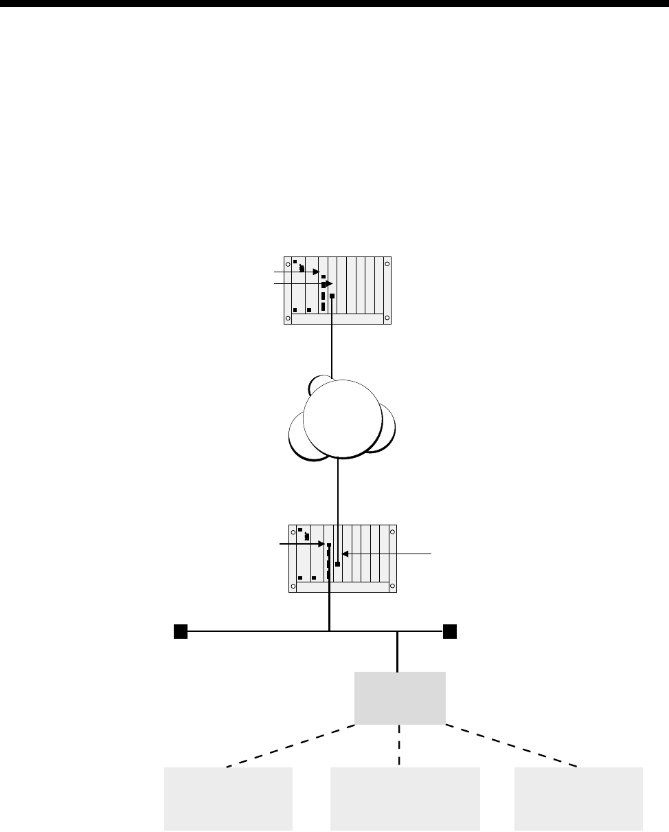
3-8 Resource Manager (RM)
10003497.00 Rev.5
Management
The Resource Manager supports local management via the RM Ethernet LAN port
and Utilities (DB9) port. It also supports remote management using IP over Frame
Relay within a TimeFrame Virtual Line, and UMP (User Management Protocol) over
a D- or B-channel. Up to 30 simultaneous OmniVision IP sessions can be active.
Standard management protocols such as SNMP (Simple Network Management
Protocol), TFTP (Trivial File Transfer Protocol) and Telnet can be used for
management along with Jtec’s proprietary UMP. A diagram of a typical management
scenario is shown below.
ISDN
RM
BRMT
Brisbane node
RM Ethernet
LAN Port BRMT
Sydney node
Network
Management
System
Telnet Client
to
Sydney node
SNMP/UMP Manager
(e.g. OmniVision)
to Brisbane node
TFTP Server
to
Sydney node
LAN

System Configuration 3-9
© 1993–2000 Jtec Pty Limited
Configuring the Management IP Address
To use IP-based management, either via the Ethernet LAN port or remotely, a
Management IP Address must be associated with each RM. The Management IP
Address is the same IP address that is given to the Ethernet LAN port on the RM. The
Management IP Address and hence the LAN Port IP Address can be set in the
following ways:
•Using Bootp
•Using RM Module configuration.
Setting Management IP Addresses using Bootp
The RM supports the Bootstrap Protocol (Bootp). The RM uses this to determine the
IP Address and Subnet Mask associated with the Ethernet LAN Port. To use this
feature a Bootp Server must be installed on the LAN. This must be capable of
accepting the Bootp requests from the RM and returning a suitable reply containing
the IP address and subnet mask.
In order to use Bootp, the RM Ethernet MAC Address must be associated with an IP
Address and Subnet Mask in the Bootp Server's database file. When the Bootp Server
receives the Bootp request, it matches the received MAC Address with the one in its
database and returns a Bootp reply with the IP address and subnet mask to the RM.
Note The Ethernet MAC Address of the RM is unique to each board. A label containing
the address is located on the back of the board (side without components). It is 12 digits long
and starts with the digits 0020BC.
OmniVision provides a Bootp Server that the RM can use to obtain its IP address.
Refer to the OmniVision User Manual for details on using the Bootp Server.
This is typically used for an unconfigured locally-managed device to determine the
initial IP address associated with the Ethernet LAN port. If a Management IP Address
is set in the RM Module Configuration then no Bootp request will be sent by the RM.
The RM does not store the IP Address, obtained from the Bootp server, in non-volatile
configuration. Each time the RM is restarted the RM requests an IP Address. To store
the IP Address in non-volatile configuration, enter it in the RM Module Configuration
dialog.
Setting the LAN IP Address using the RM Module configuration
The RM Module Configuration dialog contains a setting for the Management IP
Address and the Subnet Mask. These values are used for the Ethernet LAN port on
the RM. They are entered as dotted decimal notation. See page 3-6 for more details.
This is typically used for configuring the Management IP Address for an
unconfigured remote node, as well as setting a permanent IP address to avoid using
Bootp for a locally managed device. This method cannot be used on an unconfigured
device managed locally via the Ethernet LAN port. In this case you must use the
Bootp configuration method.

3-10 Resource Manager (RM)
10003497.00 Rev.5
Telnet
The RM has an on-board Telnet Server that allows either a remote Telnet Client or the
OmniVision Virtual Terminal to access configuration and status information.
To connect to the RM Telnet Server using a Telnet client on a PC or Workstation, a
Management IP Address must be configured. For more information, see Configuring
the Management IP Address on page 3-9. A Telnet Client should then connect to the
Management IP Address of the RM.
To connect to the RM Telnet Server using the OmniVision Virtual Terminal, start an
OmniVision management session to the RM. Select the RM with right mouse button,
and choose Virtual Terminal.
A default logon of username ’admin’ and no password exists for the first time
connection. To get help on the list of commands supported by the RM Telnet Server
enter ? at the rm:telnet> prompt and press enter.
Note A username and password is not required when accessing the RM Telnet Server via
the OmniVision Virtual Terminal.
The RM Telnet Server provides a range of commands for managing the Flash File
System, Packet Switching, IP Routing and Bridge of the Resource Manager. See the
appropriate section for details on how those commands are used.
To exit the Telnet Server, type quit, exit or logout at the rm:telnet> prompt.
A complete set of Telnet commands is given in Appendix M.
Flash management
The RM has 4 Mbytes of onboard Flash Memory that is used for keeping non-volatile
information such as the RM configuration information, and the software image that
is executed by the RM.
The Flash Memory is set up as a file system that can contain up to 3.84 Mbytes of data
arranged as files. The configuration information and software images are each stored
as files. These files can then be exchanged between the RM and a Network
Management System using TFTP (Trivial File Transfer Protocol).
Alternatively, you can use the OmniVision Flash File Manager to examine the contents
of the RM Flash memory and transfer files via TFTP. See the OmniVision User Manual
for details.
You can examine the contents of the RM Flash File System by establishing a session
to the RM’s Telnet Server. After logging on under Telnet, a list of commands is
available for manipulating files, including renaming a file, listing available files,
deleting a file and typing a file.

System Configuration 3-11
© 1993–2000 Jtec Pty Limited
The following commands can be used to manage files contained in the RM Flash File
System. These commands can be entered at the rm:telnet> prompt:
•ls list files in the Flash File System
•dir as for ls
•cat [filename] type a file onto the Telnet screen
•type [filename] as for cat
•mv
[currentfilename][newfilename] renam e current file to n ew filenam e
•ren [currentfilename][newfilename] as for mv
•del [filename] delete a file from flash
•rm [filename] as for del.
All of the above file commands operate on files within the Flash File System. For
information on copying files into and out of the Flash File System refer to TFTP on
page 3-13.
Selecting the RM software image to run
The RM is capable of storing multiple versions of RM software images, limited only
by the amount of available space in the Flash Memory. Each version of RM software
is distinguished by a unique version number stored within the software image file
header. On startup, the RM Image Loader executes the latest version of the software
image file in the file system.
It is also possible to select an image to run in the case where multiple versions of
software are maintained on the system. To do this:
1Connect an RM Telnet Server session to the RM. A complete set of Telnet
commands is shown in Appendix M.
2Enter run with no parameters to see which image is currently active.
3Enter run < filename> to select a specific software image file in Flash to execute.
<filename> must be a valid filename that exists in the RM flash file.
If this file exists on startup it will be run regardless of what other versions of RM
software images are present in the system. If it doesn't exist, the RM Image Loader
finds the latest version available.
Note After entering the name of the file you should wait for 15 seconds before resetting the
RM to give the RM a chance to save the name of the file to Flash. Failing to wait for this time
will mean that the RM will not save the change to Flash and will restart running the same
version of software that it was previously running.
4To clear the selected image and revert to using the default image, enter run clear
at the rm:telnet> prompt
5Enter run ? to get help on the run command.

3-12 Resource Manager (RM)
10003497.00 Rev.5
Adding and deleting users
The RM Telnet Server provides commands to add and delete users of Telnet sessions
established with the RM. The default user name is admin and there is no password.
Up to eight users can be specified for the RM Telnet Server.
To display a list of currently configured users, enter the command user at the
rm:telnet> prompt. This command also displays the help for adding and deleting
users.
To add a new user, enter the command user add [name][password] at the
rm:telnet> prompt, where [name] is the user name and [password] is the
password used for the connections.
To delete an existing user, enter the command user delete [name] at the
rm:telnet> prompt, where [name] is the user name to delete from the list.
Monitor application
The monitor application is used for analysing the operation of the RM software. To
start the Monitor application, type monitor at the rm:telnet> prompt.
To see a list of commands supported by the Monitor application, type ? at the
rm:monitor> prompt.
To exit the Monitor application, type quit or exit at the rm:monitor> prompt.
Router application
The router application is used for displaying statistics associated with the internal IP
Router and Bridge in the RM. To start the Router application, type router at the
rm:telnet> prompt.
The following commands are supported in the router application and these must be
entered at the rm:router> prompt. Type ? at the rm:router> prompt to get help
on these commands.
• show stack ip route
• show stack ip cache
• show stack ip protstats
• show stack ip portstats
• show stack ip arptable
• show stack ip rarptable
To exit the router application, type quit or exit at the rm:router> prompt.
Rebooting the RM
To reboot the Resource Manager, enter the command reboot now at the
rm:telnet> prompt. The RM will shut down any current activity and reboot after
a period of five seconds.

System Configuration 3-13
© 1993–2000 Jtec Pty Limited
System, Line, Trunk and WAN port status
To view the status of the RM and the availability of Lines, Trunks and WAN Ports,
type system at the rm:telnet> prompt.
TFTP
The RM has a TFTP Client that is used to transfer files between the RM Flash File
System and an external file storage source such as the Network Management Station
disk. Typical uses for this including transferring updated RM software image files to
the Resource Manager and transferring RM configuration files from the Resource
Manager to the NMS.
To access the TFTP client, you must establish a Telnet session to the RM. Enter tftp
at the rm:telnet> prompt. A ? can be used to display the list of commands available
within the RM TFTP Client. These commands include:
connect connect to a TFTP server (e.g. connect 192.195.112.15)
put send a file to the TFTP server (e.g. put user.ini)
get receive a file from the TFTP server (e.g. get rm.bin)
status display the state of connection to a Telnet Server
quit quit the TFTP Client application
Note When using the get command to download a file, the RM deletes the file of the same
name (if it exists) from its Flash Memory before proceeding with the get operation. If the
get operation fails, the RM Flash memory will no longer contain the file of the same name.
Note that the server that you wish to connect to can also be entered when starting the
TFTP client This is done by entering, for example, tftp 192.195.112.15.
A TFTP Client must connect to a TFTP Server associated with your NMS. OmniVision
supplies a TFTP Server for use with the RM. The TFTP Server for OmniVision is added
to the startup menu when it is installed. The server starts automatically when the
NMS workstation is started.
To use the OmniVision TFTP server you must set the root directory from which files
will be sent and received. Use the Set Root menu option to set this path. This must
be a valid path accessible from your NMS workstation.
Note Ensure that the Retry Timeout in the OmniVision TFTP Server is set to at least 5
seconds. If you do not do this, a ’Disk full’ error is reported during the transfer. This is an
inaccurate error message.
In this release, the process has been automated using OmniVision’s Flash File
Manager.

3-14 Resource Manager (RM)
10003497.00 Rev.5
Serial File Transfer
The RM has an in-built XMODEM file transfer capability that you can access via the
DB9 serial port on the RM front panel. Refer to the RM section of the J1000/J5000
Installation Manual for information on connecting a PC serial port either directly using
a cable, or remotely via a dial-up modem connection.
To use the Serial File Transfer capability you will need a PC Terminal Program that
supports 9600 bit/s and the XMODEM file transfer protocol. Examples of these
programs include HyperTerminal and PROCOMM.
Starting a connection
The DB9 serial port on the RM is used for two purposes:
•OmniVision management using the proprietary JASYNC protocol, and
•Serial File Transfer.
When first connecting a Terminal program, you may need to change the port from
operating in a JASYNC mode back to File Transfer mode. To do this, enter at least ten
(10) carriage return characters by holding down the <Enter> or <Return> key on your
keyboard until the prompt Monitor> appears on the screen.
Note OmniVision automatically switches the protocol on this port back to JASYNC if it is
connected after a Serial File Transfer is established.
Commands
You can enter the following commands at the Monitor> prompt for the Serial File
transfer operation:
dir get a listing of files in the RM Flash File System.
Usage: dir
del delete a file from the RM Flash File System.
Usage: del <filename>
xrecv set up the RM to receive a file via the XMODEM protocol and store it
in the Flash File System.
Usage: xrecv <filename>
download download a file from the RM Flash File System to another module in
the chassis.
Usage: download <filename> <cardslot> <interface> <line>
Refer to the J1000/J5000 Upgrade User Note for details on downloading
files to specific types of modules in a J5000 chassis.

System Configuration 3-15
© 1993–2000 Jtec Pty Limited
Transferring a file
Proceed with the file transfer using the following steps:
1Run the Terminal program on your PC and ensure that the chosen COM port
settings are correct (9600 bit/s, no parity, 8 data bits, 1 stop bit).
2If you are remotely establishing the connection via a modem, dial the number of
the modem connected to the RM DB9 port and wait until the CONNECT message
displays on the screen.
3Set the RM into Serial File Transfer mode by pressing <Enter> until the Monitor>
prompt appears.
4Ensure that the file you are transferring to the RM does not already exist in the
Flash by entering the command dir. If the file does exist, delete it by using the
delete command.
5Set up the RM to receive the file by typing the following command at the
Monitor> prompt:
xrecv <filename>
where <filename> is the name of the file you want to store in the RM Flash File
System. Do not enter any path information into the <filename>.For example, if
the location you are transferring from is C:\OmniVision\Bootimag|rm.gz, do not
enter that full path as the xrecv <filename> – just enter rm.gz.
Note You have 90 seconds to complete step 6. If the RM times-out, repeat step 5.
6Set up your PC to upload the image using the XMODEM protocol. Typically, you
do this by selecting XMODEM as the protocol and type in the path and filename
of the file to transfer. Adapt this instruction to suit the Terminal program you are
using.
7Start the upload process and monitor the progress of the transfer by watching the
statistics presented on the terminal screen.
8When the transfer is complete, ensure that the file is in the RM. Do this by typing
dir and confirm that the file is listed, and its status is OK. Repeat steps 4 to 8 for
any subsequent files that you need to transfer.
9Once the files are transferred, and if appropriate, proceed to download them to
other modules in the chassis. If the transferred file is a new RM version, then reboot
the RM.

3-16 Virtual eXchange
10003497.00 Rev.5
Virtual eXchange
The Virtual eXchange (VX) provides a switching system suitable for a private ISDN
network. It also provides call routing, call charging and service tones within the
network. The private network can be connected to the public network, allowing calls
to be made between users of the two networks.
Configuring a private network
This section describes the steps to configure a private network and details the
parameters concerned. Some aspects of the configuration are optional, but are shown
here for completeness. The optional parameters are:
•call charging
•base number
•service tone configuration
•endless loop prevention.
For VX application examples see page 5-30 in the Applications section.
Virtual eXchange configuration
Selecting the VX option on the Control Module or Resource Manager opens the
Virtual eXchange dialog. The parameters set in this dialog affect all private network
calls on the VX.
Enable VX Select this checkbox to enable the VX. All outgoing calls will be sent initially via the
private network unless the line making the call is configured to use a ‘Preferred’ or
‘Exclusive’ TE. If the called party cannot be connected through the private network,
the call is resubmitted to the public network via a TE mode interface.
Capacity Select the number of calls to be handled by the VX. The call capacity should be set to
allow for the anticipated peak load of the VX.
Note The Control Module or Resource Manager line resource is shared between the Virtual
eXchange and the Virtual lines. Care should be taken in choosing the call capacity when the
VX is used in conjunction with Virtual lines.
Send dial tone for
en-bloc call setup of
? digits or less
Enter the number of digits, received in a call establishment message, for which you
wish to provide a dialling tone. The default value is zero.
Configuring VX service tones
The VX provides service tones that are used to indicate the progress of private analog
calls. The default cadences are based on Telstra Australia Specification 1529. To
configure the tones select the Tones button from the VX configuration dialog.
Period Two on and two off periods of the cadence can be adjusted in increments of 200 ms.
RM CM

System Configuration 3-17
© 1993–2000 Jtec Pty Limited
Configuring the VX operation
To configure the VX operation select the Operation button in the VX configuration
dialog.
Numbering
You must enter a valid range of numbers and Area Code for the VX to function
correctly.
Base number Enter the base number of the VX. This is particularly useful if you have more than
one public connection.
Minimum number in
this device Enter the lowest valid number in the range.
Maximum number in
this device Enter the highest valid number in the range.
Area code
(no escape prefix) Enter the local area code without its leading zero.
Private network charging
Private network charging is optional. The VX can be configured to provide a
combination of fixed cost per call and time charge.
Flag fall charge Specify a fixed cost per call in multiples of charge units. The maximum flag fall is
65535 units.
Charge period Specify a charge period from 1 to 65535 seconds. This parameter is multiplied by the
setting in the Each unit costs parameter.
Each unit costs Enter the cost of a unit in multiples of 0.1 cent up to 25.5 cents (1 to 255).
Endless loop prevention
Specify the maximum number of nodes that a call is allowed to pass through before
reaching its destination. The default value is 10. You must set this parameter to a value
greater than, or equal to, the length of the longest path within the private network.
Trunk module configuration
This section details the configuration settings for trunk modules used in linking
private networks and those providing access to public networks.
Private network modules
Access to private network links between VX nodes is provided by IPMNs, or DTMs
in NT mode.
Configure IPMN
Refer to page 4-6 of the Module configuration section for information on configuring
the IPMN.
Configure DTM NT
Refer to page 4-79 of the Module configuration section for information on configuring
the DTM NT.

3-18 Virtual eXchange
10003497.00 Rev.5
Public network modules
Primary Rate access to the public ISDN is provided by IPMTs. Basic Rate access is
provided by BRMTs.
Configure IPMTs
Refer to page 4-3 of the Module configuration section for information on configuring
the IPMT.
Configure BRMT
Due to the characteristics of the Basic Rate specification, the link will deactivate when
there are no active calls established across the link. To prevent link deactivation, we
recommend that the Retain Layer 2 establishment and the Disable T309 checkboxes
in the Basic Rate TE Configuration dialog for the respective BRMT are enabled.
Refer to page 4-17 of the Module configuration section for information on configuring
the BRMT.
Lineset route configuration
Configuring linesets with multiple routes allow you to develop private networks that
incorporate redundant paths and can accommodate peak traffic overflow.
Information on configuring linesets can be found on page 3-46.
Linesets used to define routes in a VX network must be configured as Non-local.
Selecting Non-local sets the following parameters:
•Linear Hunting (keep list static)
•Return cause of ‘No circuit/channel available’ to allow fallback TE & NT
resubmission.
Reverse IPMN order should be selected. Since the IPMN does not provide channel
negotiation, it is possible that, if the linesets are in the same order, calls received
simultaneously from an E1 link and the VX will collide. Reversing the order lessens
the chance of call collision. Reversal should only be at one end of the private link.
Control Module/Resource Manager configuration
The following parameters are associated with the configuration of a private network:
Manager access
number This must be configured. If it is left blank, all calls will be connected to the UMPE
(User Management Protocol End), the end point for OmniVision connections.
Allow resubmission
to TE Enable to allow calls to be sent to the public network when VX is enabled.
Allow resubmission
to NT Enabled.
Log resubmitted
calls Disabled.

System Configuration 3-19
© 1993–2000 Jtec Pty Limited
TimeFrame
Overview
A TimeFrame Virtual Line is designed to provide optimum bandwidth efficiency for
data while still providing high quality of service for voice in a voice and data network.
It does this by the dynamic addition and removal of TDM slots for voice within a
packet stream containing all of the data between two sites.
A TimeFrame Virtual Line is a channel existing between two devices that contains
two distinct sections:
•a packet channel for carrying data and;
•a TDM section for carrying voice.
A single TimeFrame Virtual Line can operate up to 1472 kbit/s. Refer to page 3-22 for
restrictions on TimeFrame bandwidth allocation.
The voice circuits within a TimeFrame VL are compressed using advanced voice
compression techniques to ensure that they occupy minimum TDM bandwidth even
when active.The remainder of the TimeFrame VL channel is allocated to a Packet
Channel.
There are several aspects to configuring TimeFrame. The following list summarises
those aspects and provides cross references to the information:
•Refer to Virtual Lines on page 3-50 for information on configuring TimeFrame
Virtual Line call handling aspects such as line numbers, call establishment
methods and data rates.
•Refer to Packet Ports on page 3-34 for information on configuring a Packet Port to
provide access to the packet capabilities of a TimeFrame Virtual Line. This
includes both internal and external data devices running HDLC based protocols
such as PPP, X.25 and Frame Relay.
•Refer to Switching Packet Data on page 3-21 for information on configuring the
packet switch to switch data from the RM’s internal IP Router/Bridge and Packet
Ports onto a TimeFrame Virtual Line.
•Refer to Frame Relay PVC management on page 3-42 for details on configuring a
Packet Port to accept data from a connected device that supports the user-side
Frame Relay PVC management protocol.
•Refer to Wideband Operation on page 3-38 for information on using TimeFrame
Virtual Lines and Packet Ports in a Wideband mode (>64 kbit/s).
See the TimeFrame Virtual Line applications on page 5-3 for examples of configuring
various types of TimeFrame networks.
RM

3-20 TimeFrame
10003497.00 Rev.5
TimeFrame limitations
The following limitations apply when using TimeFrame:
•For voice calls, a 64kbit/s TimeFrame Bearer always reserves a minimum of
8kbit/s for data and end-to-end signalling. For example, a 128 kbit/s TimeFrame
Virtual Line (two bearers) reserves a minimum of 16 kbit/s, thus supporting up
to fourteen 8 kbit/s compressed voice calls. If the two bearers are used only for
data, the full 128 kbit/s bandwidth is available.
•The RM can handle a combined bandwidth of 23 x 64kbit/s (1472 kbit/s) channels
for all Category 1 Packet Ports and TimeFrame Virtual Lines. For example, an RM
cannot have an additional Category 1 Packet Port or TimeFrame Virtual Line if
there is already a 704kbit/s Category 1 Packet Port and a 768kbit/s TimeFrame
Virtual Line configured. Refer to page 3-34 for information on Category 1 Packet
Ports.
•A Subrate Virtual Line can have at most one Packet Port or at most one TimeFrame
Virtual Line as its member. A Subrate Virtual Line cannot simultaneously have a
Packet Port and a TimeFrame Virtual Line as its members. Refer to Virtual Lines
on page 3-50 for more information on Subrate Virtual Lines.
•A Packet Port and a TimeFrame Virtual Line can be members of the same
Wideband Virtual Line, as long as they do not share the same Subrate Virtual Line.
Refer to Virtual Lines on page 3-50 for more information on Subrate Virtual Lines.
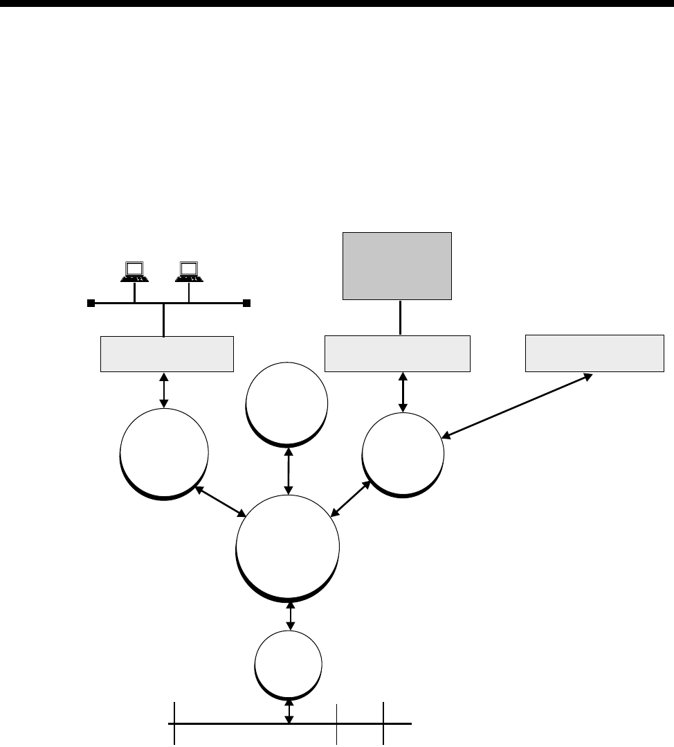
System Configuration 3-21
© 1993–2000 Jtec Pty Limited
Switching Packet Data
This section defines how the RM takes data from multiple sources and multiplexes
that over the Packet Channel within the TimeFrame Virtual Line.
The switching of packet data within the TimeFrame VL Packet Channel is controlled
by a Fast Packet Switch running on the Resource Manager. There are multiple sources
of data that can be fed into the Fast Packet Switch (FPS) from within a system. Each
of these sources of data is shown in the diagram below.
The RM Bridge/Router bridges and routes data between the locally connected
Ethernet LAN port and each of the TimeFrame VLs that support a connection to the
Bridge/Router.
The RM HDLC Data Handler takes HDLC-based data such as X.25, SNA and Frame
Relay from an externally connected device via one of the available data ports (for
example, QDLM, COMBO or SDLM). It also accepts data from internally connected
devices such as an IRM or FSM. The data from both sources is passed to the Fast
Packet Switch for switching to the appropriate destination.
RM Ethernet LAN Port
Data Port
(e.g QDLM, Combo, SDLM)
Internal Data Device
(e.g IRM, FSM)
RM
Bridge/Router
RM Call
Handler
Fast Packet
Switch
RM HDLC
Data
Handler
Packet
Channel
Handler
Signalling
External Data
Device
(e.g. SNA, X.25
Frame Relay)
LAN
TimeFrame
Virtual Line
Voice
Packet Channel

3-22 TimeFrame
10003497.00 Rev.5
To allow support for a wide range of HDLC-based protocols, the Data Handler
operates in two modes:
•encapsulation
•transparent.
In encapsulation mode, also referred to as 7E Data Handling, the incoming HDLC
packet is encapsulated in a Frame Relay frame by prepending a Frame Relay header
and an RFC1490 header. This allows the FPS to recognise it as a FR frame and switch
it accordingly.
In transparent mode, the Data Handler does not alter the incoming HDLC frame and
passes it directly to the FPS. As the frame is passed directly, it must have a Frame
Relay header to allow it to be switched.
The only protocol supported in transparent mode is Frame Relay. All other protocols
must be set for encapsulation within a Frame Relay frame.
Each of the above data sources within the TimeFrame VL are framed using the Frame
Relay protocol to allow Fast Packet Switching of all of the data within the Packet
Switch. All data is RFC1490 encapsulated to allow demultiplexing of each data source
within the TimeFrame VL.
To further enhance the bandwidth usage of the TimeFrame VL Packet Channel, data
compression can be selectively applied to each of the data sources discussed in this
section.
If data compression is enabled, the RM will try to compress all packets on the Frame
Relay route. If a compressed packet is larger than the original packet, due to it already
being compressed, the original packet is forwarded across the link rather than the
larger compressed packet. This makes the valuable trunk bandwidth more efficient.
The following sections contain more detail on the operation and configuration of each
of the components in the data path described here.
Backplane bandwidth allowance
TimeFrame Virtual Lines use the RM internal timeslots, rather than the backplane
timeslots. TimeFrame bits are Subrate-switched directly from the internal timeslots
to the trunk module's timeslots. However, if a TimeFrame Virtual Line is connected
through a BCAM-ISO, it will require two backplane timeslots to switch data into the
BCAM-ISO.
For example, a 128kbit/s Timeframe Virtual Line, connected through a BCAM-ISO
to an IPMT, requires two backplane timeslots for the IPMT and four (2x2) additional
backplane timeslots for the TimeFrame Virtual Line and the BCAM-ISO. The
additional backplane timeslots are allocated dynamically.
Refer to Appendix J – System Limits for more information on backplane timeslot
allocation

System Configuration 3-23
© 1993–2000 Jtec Pty Limited
Subrate switch usage
No Subrate switch is required to map a TimeFrame Virtual Line to a Subrate Virtual
Line, as the RM can switch Subrate bits from RM internal timeslots to the destination
timeslots.
Configuring the TimeFrame VL packet channel
This section describes how to configure a TimeFrame Virtual Line to send data packets
from devices connected to a J1000/J5000. These data packets can originate from:
•externally connected devices such as an SNA terminal or a router via a physical
data port on a COMBO or DLM, or;
•internally generated by the RM Bridge/Router from a connected LAN, or;
•internally connected modules such as the IRM or FSM, or;
•end-to-end signalling messages from the RM call handler.
All data packets sent over a TimeFrame VL must transit through the Fast Packet
Switch (FPS). The FPS is responsible for switching a data packet from a source data
service to a destination data service. A data service refers to an interface that handles
data packets. These include:
•HDLC Data Handler (Data from COMBO or DLM data ports)
•Bridge/Router Handler (Data from the RM Internal Bridge/Router)
•Packet Channel Handler (Data from a TimeFrame VL Packet Channel).
To allow the FPS to correctly switch from source to destination each data packet must
have information within the packet to allow this switching to occur. The FPS in the
RM uses Frame Relay as the switching protocol as it natively provides a number of
features which are beneficial to fast switching of frames.
Each Frame Relay frame has a standard 2 byte header which contains information
about the frame. The primary bit of information within the header is an address that
is commonly referred to as the DLCI (Data Link Circuit Identifier). In a standard
Frame Relay frame the DLCI can contain values between 0 and 1023, allowing up to
1024 unique addresses to be assigned to frames.
Note In the RM, only DLCIs 30-991 are available for use on TimeFrame Virtual Lines. All
other DLCIs are reserved.
A DLCI is used as an address for a connection between two devices within a network.
This connection is commonly referred to as a Virtual Circuit (VC). As a result of this,
each physical Frame Relay interface can theoretically support up to 1024 Virtual
Circuits going to either the same destination or switched within an external network
to different destinations. This scheme allows multiple sources of data to be
multiplexed over a single link for delivery to one or more remote destinations. The
RM can support up to 32 Virtual Circuits on each TimeFrame Virtual Line.
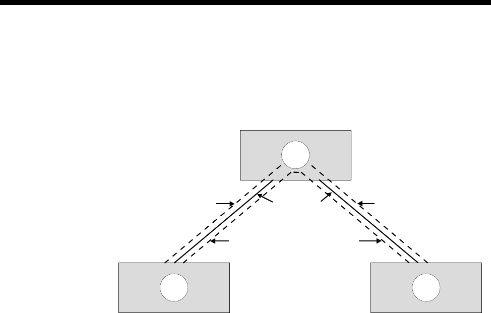
3-24 TimeFrame
10003497.00 Rev.5
The following diagram shows a three node network with four Virtual Circuits
connecting the sites over two physical links. Note that the Virtual Circuit Number is
only a label to identify the VC within the network diagram. It does not have to
correspond to the DLCI for the link. It is the DLCI that is used by the Packet Switch
to switch data packets.
All data services that communicate with the Fast Packet Switch in the RM do so
through a Frame Relay Interface. It is this Frame Relay Interface that defines the DLCI
and Virtual Circuit parameters associated with the data service, and allows data
packets to be switched within the Fast Packet Switch from source to destination.
In the RM, the Data Handler, Bridge/Router and Packet Channel Handler all have
Frame Relay interfaces associated with them.
The steps involved in configuring the TimeFrame VL to accept data consist of:
•Configuring a Frame Relay Interface and its Virtual Circuits for each data service
connected to the Packet Switch
•Associating that Virtual Circuit with one or more data service types
•Configuring the Fast Packet Switch Routing Table to switch the data packets
between source and destination data services.
A
BC
Physical Links
Virtual Circuit 1
DLCI=30
Virtual Circuit 2
DLCI=47 Virtual Circuit 4
DLCI=900
Virtual Circuit 3
DLCI=121

System Configuration 3-25
© 1993–2000 Jtec Pty Limited
Configuring a Data Handler
The Data Handler is used for connecting external or internal data devices to a
TimeFrame data service, for example, an SNA terminal or a router. These devices are
connected through either the data ports provided by modules such as a COMBO or
DLM, or internal ports such as IRM WAN ports. There are thirteen Frame Relay
Interfaces associated with the Data Handler. These interfaces are called Packet Ports.
In the configuration they are referred to as Packet Port 1 to Packet Port 13.
Note To optimise the performance of the RM we recommend that you select Category 1
Packet Ports in preference to Category 2 Packet Ports where possible. See Packet Ports on page
3-34 for a description of the differences between the two port categories.
OmniVision contains a Data Handler application to allow you to set up your devices.
See the OmniVision User Manual for details. The following information is provided
for setting up the data handler using a Telnet or Virtual Terminal session. It must be
used in conjunction with OmniVision to complete the configuration.
The following steps apply to configuring a Data Handler:
1Configure the data port to which the device is connected, for example, COMBO,
DLM or IRM. Refer to the particular module sections for more details.
2Run the Telnet application and connect to the RM to configure the Frame Relay
Interface and Virtual Circuits. Initiate the configure mode by entering configure
at the rm:telnet> prompt. A complete set of Telnet commands is shown in
Appendix M.
3View the current settings of the Data Handler being configured by showing the
Frame Relay Interface for the corresponding Packet Port using the command
show fr-int <interface>
where <interface> takes on values pktport1 to pktport13.
The Virtual Circuit determines in which mode, encapsulation or transparent, the
Packet Port, and hence the Data Handler operates. Each Packet Port only supports
one Virtual Circuit when operating in encapsulation mode. Up to 64 Virtual
Circuits are supported on each Packet Port when operating in transparent mode
with Frame Relay PVC Management enabled.
Note The Packet Port interfaces are preconfigured to operate as 7E data handlers. Because
of this, they operate in encapsulation mode and prepend a Frame Relay header on all received
frames. A DLCI has been configured for the Virtual Circuit. This is only required to be changed
if the setting is not suitable for use, for example, if a data type other than 7E encapsulation is
required, or the port is to operate in transparent mode.

3-26 TimeFrame
10003497.00 Rev.5
4To add a new Virtual Circuit to the Packet Port, the original one must first be
deleted. This is done using the command:
delete vc <interface> <vc name>
where:
<interface> takes on values pktport1 to pktport13 and is the interface from
which the Virtual Circuit is being deleted;
and <vc name> is the name of the Virtual Circuit to be deleted from that interface.
5A new Virtual Circuit is added using the command:
add vc <interface>
where <interface> takes on values pktport1 to pktport13 and is the interface
to which the Virtual Circuit is being added.
6Enter the name of the Virtual Circuit.
7Enter the DLCI for the Virtual Circuit.
Note This value is not used if the data type is set to fr for Frame Relay, and Frame Relay
PVC Management is disabled.
8Enter the Data Type associated with the Virtual Circuit. A value of fr selects
transparent operation. All other values select the type of RFC1490 encapsulation
used on the packet. 7e is the standard proprietary encapsulation.
Note Only the High Priority data type field is used for the Packet Port interfaces. No value
should be entered for Medium and Low priority.
9Establish a manual connection between the data port to which the device is
connected, and the Data Handler on the RM, configured in the previous steps. Use
OmniVision to establish this manual connection. The manual connection is
connected from the data port, to which the device is connected, to the
corresponding Packet Port on the RM. For example, if pktport1 was configured
in steps 2 to 8 above, a manual connection would be established from the data
port to Packet Port 1. If the Packet Port contains multiple lines, each line must be
manually connected.
10 Repeat this procedure for all data ports to be connected to a Data Handler.
11 Configure the remaining required data services for the device and then refer to
Configuring the Fast Packet Switch on page 3-32 for connecting data services
together.

System Configuration 3-27
© 1993–2000 Jtec Pty Limited
Configuring the Bridge/Router
The RM contains a Transparent Bridge and an IP Router to allow traffic received on
the LAN to be routed or bridged across a TimeFrame Virtual Line. There is one Frame
Relay Interface associated with the Bridge/Router and it supports eight Virtual
Circuits, allowing up to eight Bridge/Router ports to be switched onto TimeFrame
Virtual Lines. The Bridge Filtering Database entries are aged out after five minutes.
To configure the Bridge/Router:
1Run the Telnet application and connect to the RM to configure the LAN and WAN
ports of the Bridge/Router. Initiate the configure mode by entering configure
at the rm:telnet> prompt. A complete set of Telnet commands is shown in
Appendix M.
2Configure the Ethernet LAN port to suit the network. The RM contains a show
lan command to enable you to view the settings of the Ethernet LAN port and a
set lan command to alter these settings. This command configures both the
bridging and the IP routing parameters associated with the port. To accept the
current setting of a parameter, press <enter> at the prompt for the new parameter
value.
3Configure the settings on each of the WAN ports to suit the network. The RM
contains show wan <port> and set wan <port> commands where <port>
has the value of 1 to 8. These commands allow you to view and alter the settings
of the eight RM Bridge/Router WAN ports that can be connected to the
TimeFrame trunks.
Note When setting a WAN port, one of the parameters determines whether the link is
unnumbered or not. If the link is configured as unnumbered, a further prompt for a Remote
Address is made. The Remote Address is the network address of the remote end of the
unnumbered link. This value can be entered here as an alternative to creating a static route.
If RIP is enabled on this port or a static route is entered into the static route table, the Remote
IP Address can remain at 0.0.0.0.
4The Transparent Bridge and the Spanning Tree Algorithm can be globally enabled
or disabled by using the global bridge settings. To view the settings use the
command show bridge. To alter the settings use the command set bridge.
5IP Routing and RIP can be globally disabled or enabled using the global IP settings.
To view the settings use the command show ip. To alter these settings use the
command set ip.
6To set a default IP route for the RM IP Router use the set defaultroute
command. The current setting for the default route can be viewed using the
show defaultroute command. The default route can be deleted using the
delete default route command.

3-28 TimeFrame
10003497.00 Rev.5
Note If the default route is on an unnumbered link then the Port Number of the WAN port
to which the traffic is sent must be entered. This takes on a value of 1 to 8 for WAN ports 1 to
8 of the RM Bridge/Router. If the default route is not unnumbered then enter the IP address
of the device to which the traffic should be sent.
7If RIP is not used on one or more ports, static routes may be required to allow IP
traffic to be routed from the RM IP Router. To view a list of configured static routes
use the command show staticroute. To add a static route to the routing table
enter the command add staticroute <entry> where <entry> is a free entry
number within the static routing table. The <entry> value can be determined
from the show staticroute command.
To delete a static route from the static routing table, enter the command delete
staticroute <entry> where <entry> is the entry number of the static route
to delete.
Note If you are using the RM to interconnect sub-networks of the same network over WAN
Ports, you must use Numbered WAN Ports. Using Unnumbered WAN Ports prevents
the inclusion of subnet routes in the RIP updates, and may cause improper operation of the
network.
8Each of the eight WAN ports must be connected to a TimeFrame Virtual Line via
the Packet Switch routing table. The following table shows the mapping between
the WAN port number, the Port ID and the Port DLCI. The WAN Port number is
configured using the set wan <port> command. This information is used in
the Packet Switch routing table that connects the Bridge/Router to that WAN port.
For example, to connect WAN port 2 from the Bridge/Router to Packet Channel
Handler trunk2, an entry must be added to the Packet Switch Routing Table which
has the following settings:
•Port 1 ID set to router
•Port 1 DLCI set to 52
•Port 2 ID set to trunk2
•Port 2 DLCI set to correspond to a valid Virtual Circuit within the trunk2 Frame
WAN Port number Port 1 ID Port 1 DLCI
1router51
2router52
3router53
4router54
5router55
6router56
7router57
8router58

System Configuration 3-29
© 1993–2000 Jtec Pty Limited
Relay Interface
•The Data Type set to all.
Note The values for Port 1 DLCI are fixed and cannot be changed. This DLCI value can
however be mapped to an alternative value if required by switching this entry to a Virtual
Circuit within Packet Channel Handler that has the required DLCI.
9Configure the remaining required data services for the device and then refer to
Configuring the Fast Packet Switch on page 3-32 for connecting data services
together.
Note You must restart the RM if you change any of the parameters for the IP Router or the
Bridge. This includes the use of any of the following commands:
set lan
set wan <port number>
add staticroute
delete staticroute
set defaultroute
delete defaultroute
set ip
set bridge

3-30 TimeFrame
10003497.00 Rev.5
Configuring a Packet Channel Handler
The Packet Channel Handler (PCH) is responsible for prioritising and queuing data
for the TimeFrame trunks. There are eight Frame Relay Interfaces associated with the
PCH for accessing the eight TimeFrame trunks. In the configuration they are referred
to as trunk1 to trunk8. The following steps apply to configuring a Packet Channel
Handler:
1Configure the TimeFrame Virtual Line as detailed on page 3-50.
The association between a PCH Frame Relay Interface and a TimeFrame VL is
made through the Call Establishment dialog in OmniVision when setting up a
TimeFrame Virtual Line. When configuring a TimeFrame VL, a TimeFrame Trunk
Name of trunk1 through to trunk8 is automatically assigned by OmniVision. Use
that trunk name when configuring the Packet Channel Handler (PCH) that is
associated with that TimeFrame VL. This means that there is a one-to-one
relationship between a TimeFrame VL and a PCH.
2Run the Telnet application and connect to the RM to configure the Frame Relay
Interface and Virtual Circuits. Initiate the configure mode by entering configure
at the rm:telnet> prompt. A complete set of Telnet commands is shown in
Appendix M.
3View the current settings of the Packet Channel Handler being configured by
showing the Frame Relay Interface for the corresponding trunk. To do this, use
the command:
show fr-int <interface>
where <interface> takes on values trunk1 to trunk8.
Note The trunk interfaces are preconfigured with two Virtual Circuits to pass all data across
a trunk. Each trunk can support up to 32 Virtual Circuits.
4To delete a Virtual Circuit from a trunk use the command:
delete vc <interface> <vc name>
where:
<interface> takes on values trunk1 to trunk8 and is the interface from which
the Virtual Circuit is being deleted;
and <vc name> is the name of the Virtual Circuit to be deleted from that interface.

System Configuration 3-31
© 1993–2000 Jtec Pty Limited
5To add a new Virtual Circuit to the trunk use the command:
add vc <interface>
where <interface> takes on values trunk1 to trunk8 and is the interface to
which the Virtual Circuit is being added.
7Enter the name of the Virtual Circuit.
8Enter the DLCI for the Virtual Circuit.
9Enter the Data Types and priorities of the data types associated with the Virtual
Circuit.
Note If data priority is a concern, you should use the first configured Virtual Circuit on a
trunk (i.e. DLCI 100) to set up data priority. For instance, high priority=e2e, medium
priority=7e and low priority=all. Avoid setting up too many Virtual Circuits in a trunk as
the priority scheme is not implemented across multiple Virtual Circuits. End-to-end signalling
always travels on DLCI 100.
If all data is to be passed at equal priority, enter all in the High Priority Data Type
field and nothing for the Medium and Low Priority. If the Virtual Circuit is to contain
a number of different data types that need to be prioritised, enter the data types for
High Priority, Medium Priority and Low Priority respectively.
Note Only Data Types specified in the High, Medium and Low Priority fields for a Virtual
Circuit will be passed across that Virtual Circuit. Be sure that, if you split up the data types,
you cover all data types travelling across the Virtual Circuit.
10 Repeat the appropriate parts of this procedure for creating additional TimeFrame
Virtual Line to Packet Channel Handler mappings. Also use this procedure for
adding or deleting Virtual Circuits from a Packet Channel Handler.
11 Configure any remaining data services required for the device and then refer to
Configuring the Fast Packet Switch on page 3-32 for connecting data services
together.

3-32 TimeFrame
10003497.00 Rev.5
Configuring the Fast Packet Switch
The Fast Packet Switch (FPS) is used to switch data packets between any number of
configured Frame Relay Interfaces. Each entry in the Fast Packet Switch table that
describes how to switch a packet from a DLCI on one interface to another DLCI on a
different interface is called a route. The Resource Manager’s FPS can support up to
512 routes in its route table. To configure the Fast Packet Switch:
1Establish a Telnet session to the RM. A complete set of Telnet commands is shown
in Appendix M.
2Enter configure at the rm:telnet> prompt.
3To show a list of all of the configured routes in the FPS enter the command show
fr-route.
4To show details about a specific entry in the FPS route table enter the command
show fr-route <entry> where <entry> is the number of the entry in the
FPS route table.
5To add an entry into the FPS route table enter the command add fr-route
<entry> where <entry> is an unused entry number in the routing table. Use the
show fr-route command as described above to find an unused entry in the
FPS route table.
Note To replace an existing FR route entry, enter the <entry> number corresponding to
the route that you want to replace.
When adding a FPS route entry, enter the information as prompted. Note that each
FPS route entry entered is bi-directional so packets will be switched both ways
between the Port 1 and Port 2 values entered.
6Enter the Port 1 Frame Relay Interface ID using the identifier (for example,
pktport1) from the appropriate interface entered for the data services. Enter the
DLCI corresponding to the Virtual Circuit on the Frame Relay Interface to switch.
7Enter the Frame Relay Interface ID indentifier (for example, trunk1) and DLCI for
the Virtual Circuit for Port 2.
8Enable or disable compression for this FPS route entry as appropriate.
Typically, you would disable compression for an FPS route entry corresponding
to a switch between two Packet Channel Handler data services. This is because
the FPS is only acting as a transit node between the two connected devices.
Compression would typically be enabled, however, for a Data Handler or RM
Bridge/Router data service connected to a Packet Channel data service on a
TimeFrame VL. This compresses the data coming from these services and hence
reduces the amount of data actually transmitted on the TimeFrame VL.

System Configuration 3-33
© 1993–2000 Jtec Pty Limited
Note When enabling compression, the order of the Port 1 and Port 2 values as entered above
is very important. Data packets coming from Port 1 and switched to Port 2 are compressed
while data packet coming from Port 2 and switched to Port 1 are decompressed. This means
Port 1 must correspond to either a Data Handler or RM Bridge/Router data service and Port
2 must correspond to a Packet Channel Handler data service.
9Enter the Data Types switched in this FPS route entry. This field allows the Data
Type of the packet to be used to demultiplex and switch to the correct interface
when a DLCI is used to carry more than one type of data.
For example, if a Data Handler and RM Bridge/Router are switched onto Virtual
Circuits within a Packet Channel Handler, then two route entries would be
required in the FPS. This is described in Configuration of Packet Channel Handler
Service on page 3-30.
The first route entry would have:
•Port 1 set to the FR Interface ID and DLCI of the Data Handler
•Port 2 set to the FR Interface ID and first DLCI of the Packet Channel Handler
•Data Type for this entry would be 7E Data.
Note If the Data Handler is configured to operate transparently, that is data type of fr, the
Data Type for this entry must be set to all.
The second route entry would have:
•Port 1 set to FR Interface ID and DLCI of the RM Bridge/Router
•Port 2 set to the FR Interface ID and second DLCI of the Packet Channel
Handler
•Data Type for this entry would be all.
Note The data originating from the RM Bridge/Router and a Data Handler must go over
different Virtual Circuits on a TimeFrame Virtual Line.
10 To delete an entry in the FPS route table enter the command delete fr-route
<entry>.

3-34 Packet Port
10003497.00 Rev.5
Packet Port
Note In earlier releases Packet Ports were referred to as Packet Lines. Packet Lines
supported up to 64 kbit/s, Packet Ports support greater than 64kbit/s.
A Packet Port is an interface between a Resource Manager HDLC data handler and
an HDLC data device. The interface can either be internal or external to the chassis.
An external data device is usually connected to a Packet Port through a digital data
port such as a COMBO data port. The following modules and line-types are
supported by Packet Ports:
•COMBO Digital Line Interfaces
•All Digital Line Modules (DLMs) except the ADLM V.24
•All ISDN Primary Rate Modules (IPMs)
•Digital Trunk Module (DTM)
•BCAM-ISO
•IRM
•FSM
•Subrate, Non-Subrate and TimeFrame Virtual Lines.
Packet Ports only support Manual Connection.
There are 13 Packet Ports in each RM, and they can be categorised into two groups
based on their functions:
•Category 1: Packet Port 1 to 7. These support non-CCITT rate adaption, idle or
flag fill, NRZ line encoding and greater than 64kbit/s operation.
•Category 2: Packet Port 8 to 13. These support CCITT or non-CCITT rate adaption,
idle fill, NRZ, NRZI mark or NRZI space line encoding and up to 64kbit/s
operation.
Note The RM can handle a combined maximum bandwidth of 23 x 64kbit/s channels for
all Category 1 Packet Ports and TimeFrame Virtual Lines. For example, an RM cannot handle
an additional Category 1 Packet Port or TimeFrame Virtual Line if a 704kbit/s Category 1
Packet Port and a 768kbit/s TimeFrame Virtual Line are already configured.
A Packet Port can be manually connected to another data port such as an HSDM port.
In the case of a Wideband (>64 kbit/s) connection, each Packet Port line should be
manually connected to the corresponding data port line. For example, the first Packet
Port line must be connected to the first HSDM line, the second to the second, and so
on. Packet Ports do not support switch call or XSPC operations.
A Packet Port can be a member of a Wideband (non-Subrate) or a Subrate (<=64kbit/s)
Virtual Line.
RM

System Configuration 3-35
© 1993–2000 Jtec Pty Limited
Notes
A Subrate Virtual Line can have, at most, one Packet Port or one TimeFrame Virtual Line as
its member. A Subrate Virtual Line cannot simultaneously have a Packet Port and a
TimeFrame Virtual Line as its members.
A Packet Port and a TimeFrame Virtual Line can be members of the same Wideband Virtual
Line, as long as they do not share the same Subrate Virtual Line.
In the case where a Packet Port is a member of Subrate Virtual Line, calls cannot be made or
cleared from the Packet Port as it does not support switch call operations.
Backplane bandwidth allowance
A Packet Port uses internal RM timeslots that cannot be accessed by other modules.
Furthermore, a Category 2 Packet Port does not possess Subrate switch functions, so
it cannot switch Subrate bits onto a backplane timeslot. The RM sets up temporary
backplane timeslots that can be accessed by other modules, and allows Subrate
switching from the temporary timeslots to the destination timeslots. The following
table lists the number of temporary backplane timeslots required by each type of
connection.
Notes
1 The RM does not support the case where a Packet Port is a member of a Subrate Virtual
Line, which in turn is connected through a BCAM-ISO.
2 Since Category 2 Packet Ports only operate up to 64 kbit/s, there is no need to use a
BCAM-ISO.
Packet Ports use backplane bandwidth dynamically. This means that backplane
bandwidth is allocated as required. For example, a 128 kbit/s Packet Port does not
use backplane bandwidth unless it is connected.
If the RM fails to find an available backplane timeslot, it will send an alarm to the
NMS.
Packet Port
Category Manual
connection
(except
BCAM-ISO)
Manual
connection
to
BCAM-ISO
Member of
a Virtual
Line
Member of
a Subrate
Virtual Line
Member of a
Subrate
Virtual Line
through a
BCAM-ISO
10100See Note 1
2 0 See Note 2 0 1 See Note 1

3-36 Packet Port
10003497.00 Rev.5
If a backplane timeslot, which has been allocated to a Packet Port, has been
de-allocated due to an insertion of another module, the RM will locate another
timeslot for the Packet Port. If the RM fails to find an available backplane timeslot, it
will send an alarm to the NMS.
Subrate switch usage
A Subrate switch is not required to map a Category 1 Packet Port to a Subrate Virtual
Line, as the RM can switch Subrate bits from internal timeslots to destination
timeslots.
A Subrate switch is also not required if a Category 2 Packet Port is manually
connected to another port.
A Subrate switch is required if a Category 2 Packet Port is a member of a Subrate
Virtual Line.
Configuring a Packet Port
Port Configuration for Packet Port
Port ID Enter the Port ID. This is a number you can assign to uniquely identify a line and is
not related to the Port Name.
Port Name Enter the Port Name. This can be allocated to a port for easy identification. It is useful
for linesets and Virtual Lines.
Category 1 Port Setup:
Rate Adaption Only Non-CCITT is available for Category 1 ports. See page 2-8 for details.
Line Fill Set to either Idle or Flag.
Line Coding Only NRZ can be selected for Category 1 ports
Max Port Speed Set the Max Port Speed up to 1472k. The maximum port speed displayed is governed
by the difference between the aggregate Category 1 Packet Ports and TimeFrame
Virtual Line speed (i.e. 1472K), and the bandwidth already allocated to configured
Category 1 Packet Ports and TimeFrame VLs. The number of Packet Port and
TimeFrame bearer channels in use are displayed above this field.
Category 2 Port Setup:
Rate Adaption Select Non-CCITT or CCITT. See page 2-8 for details.
Line Fill Only Idle is available for Category 2 ports.
Line Coding Set to either NRZ, Mark NRZI or Space NRZI.
Max Port Speed Set the Max Port Speed up to 64k.

System Configuration 3-37
© 1993–2000 Jtec Pty Limited
Call Establishment Modes
Semipermanent Select Enable and enter the semipermanent label to set up a semipermanent call.
Hotline Enable to set up a Hotline call. In a Packet Port or Virtual Line configuration where
multiple (64kbit/s) lines are used, each line requires a Hotline number. If a subaddress
is not used, the Hotline number for subsequent (64kbit/s) lines is automatically
incremented, based on the Hotline number configured. The automatic Hotline
number increment can be disabled by checking the Don’t increment Hotline No.
checkbox.
Select XSPC to enable a Switched semipermanent connection. This is only available
with a Hotline call.
Call options Select Auto Answer to connect the incoming call to the line as soon as it is received,
irrespective of the signalling state of the connected equipment.
Advanced Settings
Select the Advanced Settings button to go to the Line configuration for the Packet
Port. See page 2-5 for further details.
Note Flag Fill must be used when connecting a Packet Port to an IRM. This means that a
Category 1 Packet Port must be used for this purpose.

3-38 Wideband operation
10003497.00 Rev.5
Wideband operation
A Wideband port is a data port or Virtual Line that is capable of operating at greater
than 64kbit/s. Narrowband ports operate at 64 kbit/s or less. The following ports
and Virtual Lines support Wideband rates:
•Category 1 Packet Ports
•TimeFrame Virtual Lines
•COMBO module data ports (version 5.00 onwards)
•HSDM data ports.
All Wideband ports exhibit similar characteristics in way they use Subrate switches
and the adaptive speed feature. Unless otherwise stated, all Wideband ports follow
the guidelines specified below.
Subrate switch usage
When a data port is configured to be less than 64kbit/s and is a member of a Subrate
Virtual Line, it requires a Subrate switch to map its Subrate bits onto a Subrate Virtual
Line.
When a Wideband data port is configured to be greater than 64kbit/s and one of its
lines is a member of a Subrate Virtual Line, all data port lines need constant delay
Subrate switches to switch all bits onto the Subrate Virtual Line. Constant delay
Subrate switches are needed to avoid differential delay between the lines. For
instance, a 120kbit/s data port that is a member of a Wideband Virtual Line requires
two Subrate switches.
Note Subrate switches are not required for switched calls between data ports.
Constant delay Subrate switches can be found in the following modules:
•MFCM V.5.01 or later
•COMBO V5.00 or later
•HSDM.
Appendix Q lists the number of constant- and variable-delay Subrate switches for each
module.
Note An insufficient number of Subrate switches will result in corrupted data during
transmission. An alarm is sent to the NMS if there are not enough Subrate switches to handle
the call.
If a module that has been assigned to provide Subrate switches for a data port is
disconnected, the RM locates other Subrate switches in the chassis for that data port.
If the RM fails to locate available Subrate switches, an alarm is sent to the NMS.
RM

System Configuration 3-39
© 1993–2000 Jtec Pty Limited
Subrate switches are assigned dynamically. This means that they are only assigned
to a port when the port is connected.
The exception to the Subrate switch usage rule are Category 1 Packet Ports and
TimeFrame Virtual Lines. These can switch Subrate bits from internal RM timeslots
to destination timeslots.
Adaptive speed feature
Under normal circumstances, a Wideband port uses its configured speed to connect
to another port or trunk. If the speed of the connected device is lower than the speed
of the Wideband port, the port adapts to the speed of the connected device.
The adaptive speed feature is supported in a connection:
•between a Wideband port and a trunk, or
•between a Wideband port and a Virtual Line (Subrate or Wideband).
This feature is not supported in a connection between two Wideband ports, such as
between a Packet Port and a HSDM port.
A Wideband port adapts to the speed of the connected device only if the Wideband
port is operating in non-CCITT rate adaption mode, and its configured speed is higher
than the speed of the connected entity. In the case where the configured Wideband
port speed is lower than the speed of the connected device, the Wideband port
maintains its configured speed.
For example, when an HSDM port is configured to 64 kbit/s, and it is a 32 kbit/s
member of a Subrate Virtual Line, it adapts to the 32 kbit/s or to the speed at which
it is connected. The following diagram illustrates this.
Since the connected speed may be different from the configured speed, the diagnostic
dialog of the Wideband port displays the connected speed of the Wideband port.
HSDM
Port 1
64 kbit/s
32k
Subrate
VL

3-40 Wideband operation
10003497.00 Rev.5
Connections through a BCAM-ISO
When making a Wideband connection over a switched ISDN, a BCAM-ISO is
required to compensate for differential delays between the individual ISDN lines.
The BCAM-ISO can only aggregate up to 16 B-channels. This limits the bandwidth
of a Wideband connection through BCAM-ISO to 1024 kbit/s.
Note The BCAM-ISO only supports mode 0, 1 and 3 operation when connecting to
Wideband ports other than a Time Frame Virtual Line. A TimeFrame Virtual Line supports
only modes 1 and 3.
There are two methods of connecting a Wideband port through a BCAM-ISO:
•Manually connect the Wideband port to the BCAM-ISO. The BCAM-ISO is then
configured to make the connection to the remote device.
•Switch calls from the Wideband port directly to its destination through the
BCAM-ISO.
Resynchronisation
Due to the resynchronisation performed by the network, the BCAM-ISO can
experience synchronisation errors. BCAM-ISO mode 3 is capable of detecting and
automatically resynchronises if a network resynchronisation happens.
Mode 0 and 1, however, rely on the end-device to detect and handle network
resynchronisation. If a network resynchronisation is detected, the end-device should
disconnect and, if applicable, reconnect the call.
When operating in modes 0 and 1, end-devices should provide an end-to-end
protocol that monitors the link sanity. The end-to-end protocol provides a means of
detecting and handling network resynchronisation.
Manual connection to BCAM-ISO
The following point should be noted when configuring manual connections between
Wideband ports and BCAM-ISOs:
•All manual connections, except for Packet Ports and TimeFrame, must be made
as 'Internal' connections, not external.

System Configuration 3-41
© 1993–2000 Jtec Pty Limited
Switch calls through BCAM-ISO
The following points should be noted when configuring Wideband ports to make
switched calls via BCAM-ISOs:
•Set Wideband port's Outgoing TE to BCAM-ISO
•Receiving device Lineset setup:
•Create a lineset on the destination device for the destination Wideband port
•Add all the BCAM-ISO interface 0 lines to this lineset
•Also add all of the lines from the Wideband port to the same lineset.
Notes The Wideband port lines must come after the BCAM-ISO lines in the lineset.

3-42 Frame Relay PVC management
10003497.00 Rev.5
Frame Relay PVC management
Frame Relay PVC management provides a means to verify the integrity of a Frame
Relay link by allowing you to detect changes in the state of each of the link’s
Permanent Virtual Circuits (PVC). It also allows you to detect the failure of a PVC
and recover it. Frame Relay PVC management is only implemented on the RM’s
Packet Ports.
The PVC management procedures include:
•notification of the addition of a PVC
•detection of the deletion of a PVC
•notification of the availability (active) or unavailability (inactive) state of a
configured PVC. Inactive means that the PVC is configured but is not available to
be used. Active means that the PVC is available to be used
•link integrity verification.
The RM supports network-side PVC management procedures with the ITU-T Q.933,
Annex A and ANSI T1.617a, Annex D protocols on Packet Ports that have been
configured to carry data in transparent (Frame Relay) mode. These procedures allow
the RM to connect to frame relay devices that operate user-side PVC management
procedures.
Note Network-side PVC management procedures must be enabled on a Packet Port when
- and only when - user-side management procedures are enabled on a connecting Frame
Relay device. Some Frame Relay-capable devices that operate user-side procedures, such as
the IRM, do not allow them to be disabled. Consequently, the RM must always have
network-side procedures enabled while connected via a Frame Relay link to such a device.
Polling
During PVC management, the user side periodically requests the network side to
verify the integrity of the link and to report on the status of each of the link's PVCs;
the network side responds in turn. This cycle of request and response is called the
polling cycle, and the interval between subsequent status requests is called the polling
interval. The following diagram illustrates the polling feature.
Frame
Relay
Device
RM
Status Enquiry
Status Response
Frame Relay Link
Network
Side
User Side
RM

System Configuration 3-43
© 1993–2000 Jtec Pty Limited
The tables below define the parameters that control the polling cycles. Table 1 defines
the parameters in the user-side equipment, and Table 2 defines the network-side
parameters that may be configured for a transparent-mode Packet Port. The default
parameter values given should be suitable for most circumstances. Varying these
parameters will alter the sensitivity of the link to errors and changes in state.
Table 1 – User-Side PVC Management Parameters
Table 2 – RM (Network-Side) PVC Management Parameters
Parameter Range Default Description
Polling interval 5-30 10 Specifies the interval, in seconds, between
successive status requests
Full status polling
counter
1-255 6 Specifies how often, in terms of polling
intervals, a full report of the status of all link
PVCs is requested. For example, with the
default value a full status report will be
requested on every 6th status request.
Error threshold 1-10 3 The number of errors detected before
declaring the interface down. Note that this
should be less than or equal to the monitored
events count.
Monitored events
count 1-10 4 The number of status polling intervals over
which the error threshold is counted. Note
that if this is set to a value much less than
the full status polling counter then the link
could go in and out of error condition without
the user equipment or network being
notified.
Parameter Range Default Description
Polling verification
interval 5-30 15 Specifies the interval, in seconds, to wait for
a status enquiry message before recording
an error. Note: this should be greater than
the polling interval.
Error threshold 1-10 3 The number of errors detected before
declaring the interface down. Note that this
should be less than or equal to the
monitored events count.
Monitored events
count 1-10 4 The number of status polling intervals over
which the error threshold is counted. Note
that if this is set to a value much less than
the full status polling counter then the link
could go in and out of error condition without
the user equipment or network being
notified.
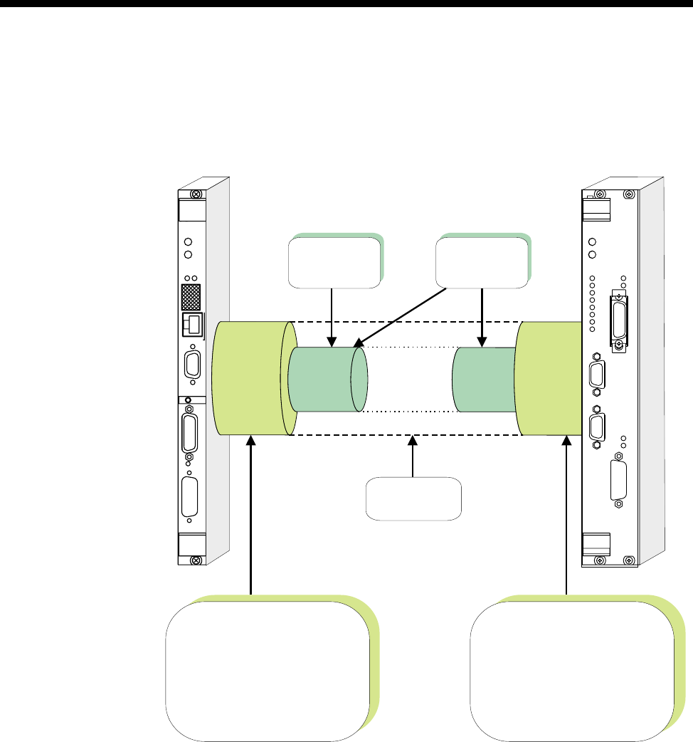
3-44 Frame Relay PVC management
10003497.00 Rev.5
Example – Linking from an IRM to an RM Packet Port
This example describes the configuration of a Frame Relay connection between an
RM and an IRM in the same chassis. The following diagram summarises this
connection.
Configuration
The configuration process has the following steps:
1Configure an IRM WAN port to use the Frame Relay protocol. Set the protocol
parameters listed in Table 1 for the user-side PVC management procedures. Use
the T1.617a protocol and the default parameter values listed in the table.
2Add a Virtual Circuit (also referred to as a ’channel’) to the chosen IRM WAN port.
3Configure a Packet Port on the RM. Specify the same speed as the chosen IRM
WAN port. Enable network-side PVC management procedures using the T1.617a
protocol, and the default parameter values listed in Table 2.
OK
ALARM
CALL 1
CALL 2
CALL 3
CALL 4
ON
TEST
BUSY
ERROR
STAT
DATA
STAT
DATA
2
1
C
LMS
IRM
X.21
ALARM
OK
UMT LAN
C10BT
RM 5000
RM IRM
Packet
Port WAN
Port
Virtual
Circuit
Virtual
Circuit
Data protocol = Frame Relay
User-side PVC management
procedure parameters:
Management Protocol = T1.617a
Polling Interval = 10
Full Status Polling Counter = 6
Error Threshold = 3
Monitored Events Count = 4
Network-side PVC management
procedure parameters:
Management Protocol = T1.617a
Polling Verification Interval = 15
Error Threshold = 3
Monitored Events Count = 4
Manual
Connection
Data Type:
Frame Relay (Same DLCI)

System Configuration 3-45
© 1993–2000 Jtec Pty Limited
4Configure a Virtual Circuit on the chosen Packet Port, with a DLCI to match the
Virtual Circuit configured on the IRM WAN port in step 2. Set the following Virtual
Circuit data priorities:
High:Frame Relay (’FR’)
Medium:(none)
Low:(none)
5Create a manual connection between the chosen IRM WAN port and the Packet
Port.
The link between the IRM WAN port and the RM Packet Port should now be ready
to carry Frame Relay-encapsulated data. Procedures for establishing data routes to
the RM Packet Port are covered on page 3-25. Configuration of IRM WAN ports is
dealt with in the IRM module configuration on page 4-215.
Repeat the above steps for each Virtual Circuit to added between the IRM and the
Packet Port.
Note When enabling PVC management on a Packet Port, each of the port’s PVCs must be
configured to carry only Frame Relay-encapsulated data by setting the data type of fr.

3-46 Linesets
10003497.00 Rev.5
Linesets
A lineset is one or more lines which share a number or range of numbers. These lines
are referred to as members of a lineset. A lineset can consist of up to 220 lines and any
combination of line types.
You can configure multiple linesets with an overall total of up to 1000 members per
device.
Note The total number of linesets available for the RM and CM is shown in Appendix I.
Linesets are used to direct incoming calls: they have no effect on outgoing calls. They
are particularly useful for directing incoming calls into a number of PABX ports which
share a common function.
To create a lineset, you define one or more lines as members. This means that a single
number, or a range of numbers apply to all the lines in the set. You can attach:
•a single number to several lines
•a range of numbers to several lines
•a range of numbers to a single line.
It is possible, but not very useful, to define a lineset with a single number and a single
line. A single line can also be a member of more than one lineset. This is useful if you
need to attach two or more different ranges of numbers to the same lines.
Lines in a lineset may have individual line numbers as well as the lineset numbers,
so that they can also be called directly.
Lineset members may be identical, so that if one is busy another can be chosen for an
incoming call. Alternatively, they may all be of different types, with a single number.
This means that different types of calls are accepted by the appropriate type of line.
For example, a fax call is accepted on a fax line and a telephone call is accepted on a
telephone line.
Linesets may include TimeFrame Virtual Lines, but not Subrate, non-Subrate or
broadcast Virtual Lines. For more information see Virtual Lines on page 3-50.
Matching linesets
When a call establishment message is received from the ISDN, any linesets which
have been defined are examined for a match first, before individual lines. If a lineset
which matches the called party number is found, individual lines are not examined,
even if the call is not accepted by the lineset.
If a lineset is found which matches the number in the call establishment message, the
individual members of the lineset are examined until one which meets all the call
acceptance criteria is found. When a match is found, the call proceeds as if it were
specifically for that line.
RM CM

System Configuration 3-47
© 1993–2000 Jtec Pty Limited
If no suitable line is found in the lineset, a message is sent to the network indicating
that the call has been rejected. This will reflect the actual cause of the rejection as
closely as possible. For example, a lineset could consist of a fax line and a telephone
line. If a setup for a fax call is received while the fax is busy and the telephone is idle,
the call will be rejected. The cause message sent would be USER BUSY, not
INCOMPATIBLE DESTINATION.
The lines in the lineset are examined in the same order in which they were entered
during configuration. The search can be conducted by:
•Linear hunting
The search always starts at the top of the Associated Lines List (the Associated
Lines List contains all lines which are members of a lineset). The call is directed
to the first idle member on the list. If no idle members are found, the call is rejected
with a BUSY indication.
•Cyclic hunting
The search always starts one member further down the Associated Lines list than
the previous call, regardless of whether that call was successful. The call is directed
to the first idle member encountered. Once the call has been serviced, the list is
rotated so that the next member is placed at the top of the list. This ensures that
calls are distributed as evenly as possible amongst members, and that lines that
are faulty but not blocked will not cause the service to fail continuously. If no idle
members are found, the call is released with a BUSY indication.
Notes
•A new lineset is automatically created when you configure the minimum and maximum
numbers for an IPMN or a BRMN. A lineset for an IPMN contains 30 B-channels and
one D-channel while a lineset for an BRMN contains two B-channels and one D-channel.
•A new lineset is automatically created when you enter the line number for a BCAM or
BCAM-ISO. This lineset always contains the eight channels of the BCAM, or sixteen
channels of a BCAM-ISO, regardless of the line speed used.
•In both the above cases, the lineset mechanism is used by the Control Module or Resource
Manager to effect the B-channel aggregation of the ISDN NT function. You should not
change these linesets.

3-48 Linesets
10003497.00 Rev.5
Configuration
To configure a lineset, choose Linesets from the Edit Menu in OmniVision.
Parameters
Minimum Enter the minimum number in the range, or the only number.
Maximum Enter the maximum number in the range.
Notes
•The lineset line number format is a full local number, as received in the called party
identification on incoming calls.
•The base number is not used in the calculation of lineset numbers. This is different from
the line numbers of individual lines. Refer to Line Numbers on page 2-15 of the
Parameters section for further information.
Reverse IPMN
order Select this if you want IPMN lines to be listed in reverse order. See Configuring IPMN
on page 4-6 for more information.
Attributes for destination type
Select from Forced TE resubmission on match, Local, Non-local or Custom. The
custom selection allows you to edit the following parameters:
Call delivery and line member attributes
Select from the following attributes:
Linear Hunting Select this option to direct all calls to the first idle member on the Associated Lines
list. See above for a complete explanation of this option. This is the default setting for
Non-local attributes.
Cyclic Hunting Select this option to evenly distribute calls amongst members of the Associated Lines
list. See above for a complete explanation of this option. This is the default setting for
the Local attributes.
Allow call to be sent back on originating interface if it is a member of this lineset
This is automatically enabled when you choose Local attributes.
Match on exact
length Enable if you require the number in an incoming call to be matched exactly to the
line member rather than to the lineset.
Action when call cannot be delivered to any line of the lineset
Select from the following attributes:
Allow TE resubmission when call not originating from this device node fails
The default setting is ’Disabled’.
Return cause of “No circuit/channel available” to allow fallback TE &NT resubmission
This is automatically enabled when you choose Non-local attributes.
Do not allow TE resubmission for any cause value
This is automatically enabled when you choose Local attributes.

System Configuration 3-49
© 1993–2000 Jtec Pty Limited
Reference Master Priorities
The Reference Master provides a 2 Mbit/s clock to the backplane which is sourced
from the network. Modules that can be chosen as the Reference Master include ISDN
PRA TE, ISDN PRA NT, E1TE, E1NT and ISDN BRA TE.
Default priorities
You can change the priority for each of the modules, set each one to the default
individually, or set all modules to the defaults shown below.
Australian defaults
1 ISDN PRA TE
2 ISDN PRA NT
3 E1TE
4 ISDN BRA TE
5 E1NT/DTM
6 HSDM
7 COMBO V.5.00 and above
ROW defaults
1 ISDN PRA TE
2 ISDN BRA TE
3 ISDN PRA NT
4 E1TE
5 E1NT/DTM
6 HSDM
7 COMBO V.5.00 and above
RM CM

3-50 Virtual Lines
10003497.00 Rev.5
Virtual Lines
A Virtual Line (VL) is a named group of lines which can be treated as one entity for
call control purposes. It can have the same call control parameters, such as
semipermanent label, line number, Hotline number, and so on, as a physical line.
A Virtual Line has no physical attributes itself: it is defined by its members. However,
its member’s call control parameters are not used by the Virtual Line when initiating
or receiving calls.
The four different types of Virtual Line are:
•TimeFrame Virtual Line
•Subrate Multiplexed Virtual Line
•Non Subrate Multiplexed Virtual Line
•Broadcast Virtual Line.
The parameters available to you when creating Virtual Lines are described on page
3-56. For detailed instructions on setting up Virtual Lines refer to the OmniVision User
Manual or OmniVision Help. For some typical configuration settings refer to the Subrate
Virtual Line applications on page 5-24.
Note The total number of lines involved in Virtual Lines cannot exceed 400 per device.
TimeFrame Virtual Line
TimeFrame Virtual Lines allow a packet data stream and compressed voice calls to
share a single bearer channel. The packet data bandwidth is dynamically adjusted,
depending on the number of voice calls using the bearer. Voice calls are compressed
using 8kbit/s MP-MLQ voice compression. When a voice call is added, the packet
data bandwidth is reduced by 8kbit/s. Similarly, when a voice call is removed, the
data bandwidth is increased by 8kbit/s. This dynamic adjustment of the packet data
bandwidth maximises the use of the bearer circuit.
Note TimeFrame Virtual Lines do not support 16 kbit/s MP-MLQ voice compression. They
do support compression on the LDCM and MFCM. Refer to page 4-189 and page 4-193 for
details on using TimeFrame with LDCMs and MFCMs respectively.
Call establishment methods
A TimeFrame Virtual Line is the entity that connects to the bearer channel. It can be
configured to:
•establish a switched call on demand;
•establish a long-held switched call (XSPC), or;
•use a permanent connection (manual connection or semipermanent connection).
RM
RM CM

System Configuration 3-51
© 1993–2000 Jtec Pty Limited
In the case of demand-established calls, the TimeFrame Virtual Line maintains the
call whenever there is packet data present, or voice calls are using the bearer. An
activity timer shuts down a call if there is no data activity for a configured period of
time. The number dialled for demand-established calls or XSPC is determined by the
TimeFrame Virtual Line Hotline number.
For XSPC calls, the calling end must have XSPC enabled in Call Establishment modes.
Similarly, the called end must have Auto Answer enabled.
Note For demand-established TimeFrame Virtual Lines, do not enable Auto Answer at
either the called or calling end. Enabling Auto Answer will prevent the Activity Timer from
operating correctly and therefore the TimeFrame Virtual Line will not be shut down
automatically.
When the TimeFrame Virtual Line contains more than one line (its data rate is greater
than 64 kbit/s) there are several points to note about the use of the Port Number,
Subaddress, Hotline Number and Hotline Subaddress fields.
Port Number with no Subaddress
If you enter a number in the Port Number, and the Subaddress has no number, the
RM automatically increments the Port Number for each line. For example, on a
192 kbit/s TimeFrame Virtual Line with a Port Number of 93640080, the Port Number
for Line 0 is 93640080, for Line 1 is 93640081, and for Line 2 is 93640082. This ensures
that each line has a unique number.
Port Number with a Subaddress
If you enter a number in the Port Number and Subaddress fields, the RM does not
increment the Port Number for each Line. Instead, it increments the Subaddress for
each line. For example, on a 192 kbit/s TimeFrame Virtual Line with a Port Number
of 93640080 and Subaddress 10, each line has the following values:
This ensures that each line has a unique number.
Line Port Number Subaddress
0 93640080 10
1 93640080 11
2 93640080 12

3-52 Virtual Lines
10003497.00 Rev.5
Hotline Number with a Hotline Subaddress
If you enter a Hotline Number and Hotline Subaddress, the RM automatically copies
the Hotline Number to each line in the TimeFrame Virtual Line, and increments the
Hotline Subaddress for each line. For example, on a 192 kbit/s TimeFrame Virtual
Line with a Hotline Number of 93900080 and Subaddress 10, each line has the
following values:
This ensures that each line dials a unique number when establishing a call.
Hotline Number with no Hotline Subaddress
If you enter a Hotline Number and no Subaddress, you must use the
Don’t Increment Hotline No. option to control the operation of the automatic
incrementing of the Hotline Number.
If the option is disabled, the Hotline Number is incremented for each line in the
TimeFrame Virtual Line. If the option is enabled, the Hotline Number is not
incremented, but is instead copied to each line.
The following table shows how the Hotline Number of a 192 kbit/s TimeFrame
Virtual Line is affected by enabling or disabling the Don’t Increment Hotline No.
option:
When configuring a TimeFrame Virtual Line with multiple lines, the two best
methods for setting the numbering are:
1Enter the Port Numbers and Subaddress with matching Hotline Numbers and
Subaddresses at the other end
2Enter a Port Number and no Subaddress, and then enter a matching Hotline
Number at the other end with Don’t Increment Hotline No. disabled.
For an example of how this is used with BCAM-ISO, refer to TimeFrame Applications
on page 5-3.
Line Hotline Number Hotline Subaddress
0 93900080 10
1 93900080 11
2 93900080 12
Line Enable
Don’t Increment Hotline Number Disable
Don’t Increment Hotline Number
0 93900080 93900080
1 93900080 93900081
2 93900080 93900081

System Configuration 3-53
© 1993–2000 Jtec Pty Limited
TimeFrame resources
TimeFrame Resources are the end points used to terminate and originate voice calls
that are to be switched onto or off a TimeFrame Virtual Line. They require no
configuration except that they are added to linesets to receive voice calls onto a
TimeFrame Virtual Line. TimeFrame Resources are allocated individually. There must
be at least one TimeFrame Resource allocated for voice to operate over a TimeFrame
Virtual Line.
Refer to Appendix I for details on the maximum number of TimeFrame Resources in
a system.
Note The number of TimeFrame Resources allocated need only correspond to the total
number required across all TimeFrame VLs. For example, if four TimeFrame VLs are
configured and each was to carry a maximum of three voice calls, then only 12 TimeFrame
Resources need be allocated. Doing this will reduce the number of lines used within the device,
thereby allowing them to be used in other applications.
Packet Channel
The packet data stream consists of a combination of end-to-end signalling data for
the voice calls, IP router data and HDLC data. This data is switched through the Fast
Packet Switch to the portion of the bearer channel not being used for voice calls.
Set the maximum data rate of the TimeFrame Virtual Line using the Max Port Speed
parameter. This can be up to 1472 kbit/s. Refer to TimeFrame limitations on page 3-20
for limitations on data rates.
You can configure the minimum data bandwidth for a TimeFrame Virtual Line to
ensure that there is always a guaranteed portion allocated for sending data. Refer to
Call Establishment Modes on page 2-11.
If a demand-established TimeFrame Virtual line is initiated by data passing through
the Packet Switch, and the call fails, the call is retried at intervals of 15 to 20 seconds.
During these intervals, the Packet Switch discards any data destined for the channel
that is being established.
Matching a voice call to a TimeFrame Virtual Line
The TimeFrame Virtual Line selected for a particular voice call is determined by
matching the called party number with the Hotline number of a TimeFrame Virtual
Line. In the case where there is a match with more than one TimeFrame Virtual Line,
the bearer that has the minimum free capacity to receive voice calls is selected. Since
the numbers dialled for voice calls are typically PABX extension numbers, the
numbers must be translated to select the required TimeFrame Virtual Line. The
number translation is achieved using Number Checking to modify the called party
number to that of the Hotline Number of the TimeFrame Virtual Line on which the
call is to be sent. In the case of a Wideband TimeFrame Virtual Line, the called party
number is translated, using Number Checking, to the Hotline Number of the first line
of the TimeFrame Virtual Line on which the call is sent. The dialled number is passed
to the remote end in the end-to-end signalling data for the call, and presented as the
called party number at the remote end.

3-54 Virtual Lines
10003497.00 Rev.5
SAM channels
A SAM channel can be manually connected to an RM’s Packet Port, making it a
member of a TimeFrame Virtual Line. This is made possible by using the RM’s 7E
data handling. All on-board RM SAM channels can be used in this way. The SAM
channel cannot be a member of a demand-established TimeFrame VL, as it sends data
continuously to ensure the link remains active. The Packet Port would interpret this
data as the link being busy, and would not disconnect the TimeFrame VL.
If a SAM channel is made a member of a TimeFrame VL, the Virtual Line must be an
XSPC, SPC or manually connected call.
For more information refer to TimeFrame on page 3-19. For examples of configuring
TimeFrame Virtual Lines see page 5-3.
Transit switching
TimeFrame Virtual Lines support the transit switching of voice calls onto other
TimeFrame Virtual Lines and Subrate Virtual Lines. VCMs and SRMMs cannot be
used in the node that is carrying out the transit switching as they do not support
TimeFrame. The switching is however supported over Subrate switches in modules
like the LDCM, MFCM, COMBO and HSDM.
Subrate Multiplexed Virtual Line
A Subrate Multiplexed Virtual Line consists of several lines (compressed voice,
Subrate data or a mixture of both) that are subchannel multiplexed in increments of
8 kbit/s into one 64 kbit/s channel. For example, a Subrate Multiplexed Virtual Line
could consist of four EMM lines each compressed to 16 kbit/s. Refer to Appendix A —
Data rates for Subrate multiplexing for details of data rates that can be multiplexed.
A Subrate Multiplexed Virtual Line is used to optimise the capacity of the required
network bandwidth while maintaining end-to-end functionality. It is used in
point-to-point applications where multiple services are required between the two
ends.
A Subrate Multiplexed Virtual Line has most of the properties of a normal line. For
example, it has a line number, can make and receive calls and can be configured.
Manual, Hotline and semipermanent connections (where available) are possible,
providing both ends of the connection have the same subchannel allocation for
members. For example, a 16-16-32 kbit/s Virtual Line is not compatible with a
32-16-16 or a 16-32-16 kbit/s Virtual Line.
Virtual line members cannot make individual calls: they can only participate in a call
made to or from the Virtual Line. However, single members may cause the Virtual
Line to initiate a switched call in the case of demand-established Virtual Lines.
Note In the case of semipermanent connections, the corresponding members at either end
are connected as if each had a dedicated semipermanent connection.
RM CM

System Configuration 3-55
© 1993–2000 Jtec Pty Limited
Non Subrate Virtual Line
A Non Subrate Virtual Line is an association of one or more lines per device. These
can be any type of line, including other Virtual Lines.
Notes A Non Subrate Virtual Line can have another Non Subrate Virtual Line as a member.
This is a useful feature, but you should ensure that a Non Subrate Virtual Line is not defined
as a member of itself. OmniVision does not check for this.
Each Non Subrate Virtual Line can have a maximum of 20 members. If you require more than
20 members, make a second Non Subrate Virtual Line containing the extra members, and
make it a member of the first Subrate Virtual Line.
A Non Subrate Virtual Line does not, in itself, have any line characteristics such as
bearer capability, line number and so on, as it is not used to independently initiate or
terminate calls. Its purpose is to group together other lines for the forwarding of call
control bits from OmniVision.
You allocate lines to a Non Subrate Virtual Line in the same way as you would allocate
them to a Subrate Multiplexed Virtual Line. However, more than eight members are
allowed and you do not need to allocate Subrate bits as they are not required by a
Non Subrate Virtual Line.
Membership of a Non Subrate Virtual Line has no effect on the ability of a line to
make and receive calls. Calls can be made and received by a member of a Non Subrate
Virtual Line without any effect on the other members of the Non Subrate Virtual Line.
Therefore, you configure members of a Non Subrate Virtual Line in the same way as
you would if their association did not exist.
When a call request is made to the Non Subrate Virtual Line by one of its members,
it establishes multiple calls associated with all of its members. This means that
multiple calls and connections can be executed with a single request.
Wideband Virtual Line
A Wideband Virtual Line exhibits all the same characteristics as a Non Subrate Virtual
Line, and is configured in the same way. The main difference is that a Wideband
Virtual Line can additionally support lines that are members of a Wideband Packet
Port and TimeFrame Virtual Line. See Packet Port on page 3-34 and TimeFrame Virtual
Line on page 3-50 for more information.
Note The RM does not support Wideband Virtual Line calls using an ISDN that requires
the BCAM-ISO to provide channel aggregation.
RM CM
RM

3-56 Virtual Lines
10003497.00 Rev.5
Broadcast Virtual Line
A Broadcast Virtual Line is similar to a Subrate Virtual Line in that it can make and
receive calls, but it has only one member.
The function of a Broadcast Virtual Line is to generate and/or receive calls on behalf
of the physical line. When a Broadcast Virtual Line makes or receives a call, the
connection is always half duplex and towards the network.
A Broadcast Virtual Line can only maintain one active call at a time. However, a
physical line can be defined as a member of a number of Broadcast Virtual Lines, each
of which can make a call to the destination represented by its Hotline number. To
initiate a true Broadcast call, the individual Broadcast Virtual Lines should be defined
as members of a Non Subrate Virtual Line. A number of calls can then be generated
from a single physical line with a single command.
Note A Broadcast call provides unidirectional data transmission from the originating
Virtual Line to the various destinations.
Parameters
Virtual Line Name Enter a unique descriptive name, up to eight characters in length.
Number Displays the Virtual Line number.
Type Displays the type of Virtual Line, that is TimeFrame, Subrate, non-Subrate or
broadcast.
Members Displays the members and where appropriate, Subrate channel allocation of the
selected Virtual Line.
Available Lines list Displays the available lines. Select the lines you want to add to the Virtual Line.
Virtual Lines list Displays names of all Virtual Lines set up.
Virtual Line
Members Lists the members of the Virtual Line and, in the case of a Subrate Virtual Line, the
Subrate channel allocation.
Config Select to configure the selected member, line or port.
Delete Select to delete the selected line from the Virtual Line members list.
Add Select to add the selected line to the Virtual Line members list.
Setup Select this button to configure the line characteristics of the Subrate Virtual Line
Line Select this button to configure the line characteristics of the Subrate Virtual Line,
directly (without entering the member screen).
Port Select to configure the TimeFrame Virtual Line.
New VL Select to create a new Virtual Line.
Subrate Select to create a Subrate Virtual Line.
Non-Subrate Select to create a non Subrate Virtual Line.
Broadcast Select to create a broadcast Virtual Line.
TimeFrame Select to create a TimeFrame Virtual Line.
Remove VL Allows you to delete the selected Virtual Line.
TimeFrame Capacity Select the number of TimeFrame Resources required for the system.
RM CM
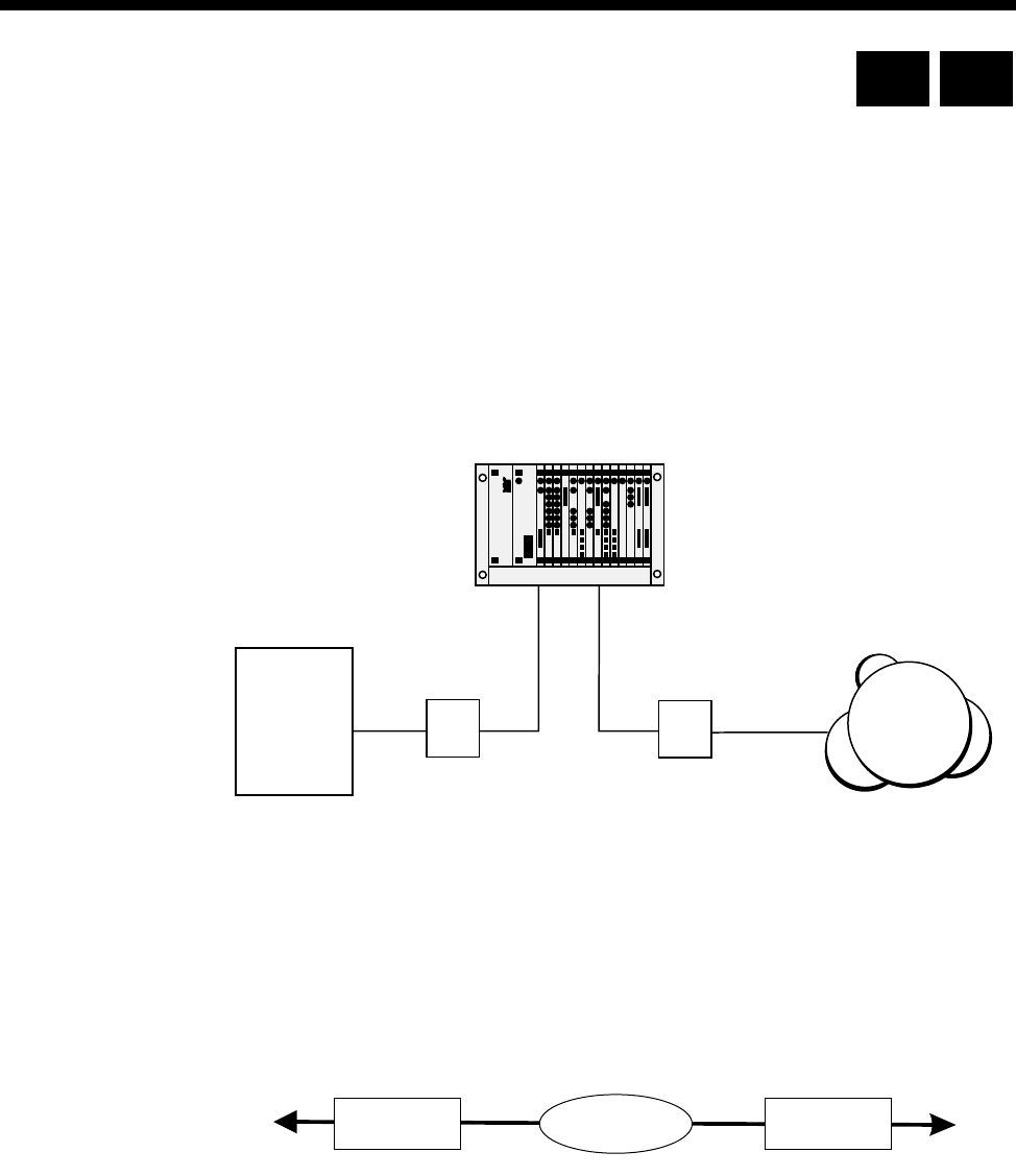
System Configuration 3-57
© 1993–2000 Jtec Pty Limited
ISDN Interworking
Introduction
ISDN Interworking provides a method of linking two ISDNs which are presented to
a device via NT1 primary rate access points. Calls originating in one ISDN can be
shipped through the device via an Interworking Unit to the other ISDN.
The following example assigns one ISDN as being provided by a NorTel DMS-100
exchange and the other ISDN as being provided by Telstra Australia. For the purposes
of discussion, the NorTel ISDN access point is denoted as Primary Rate Interface (PRI)
and the Telstra ISDN access point is denoted as Primary Rate Access (PRA).
PRA-PRI Interworking
To achieve this, the device provides an Interworking Unit through which calls are
routed. The Interworking Unit can either:
• take a call from an IPMT with PRI protocol and connect it to a call on an IPMT
with PRA protocol, or
•take a call from an IPMT with PRA protocol and connect it to a call on an IPMT
with PRI protocol.
The calls are routed through an Interworking Unit, as shown in the diagram on the
following page.
ISDN
Telstra
Australia
NorTel
DMS-100 NT1 NT1
PRI PRA
IPMT PRAIPMT PRI Transi t
Switch
To Nor t el
DMS-100 To Tel s t ra
ISDN
RM CM
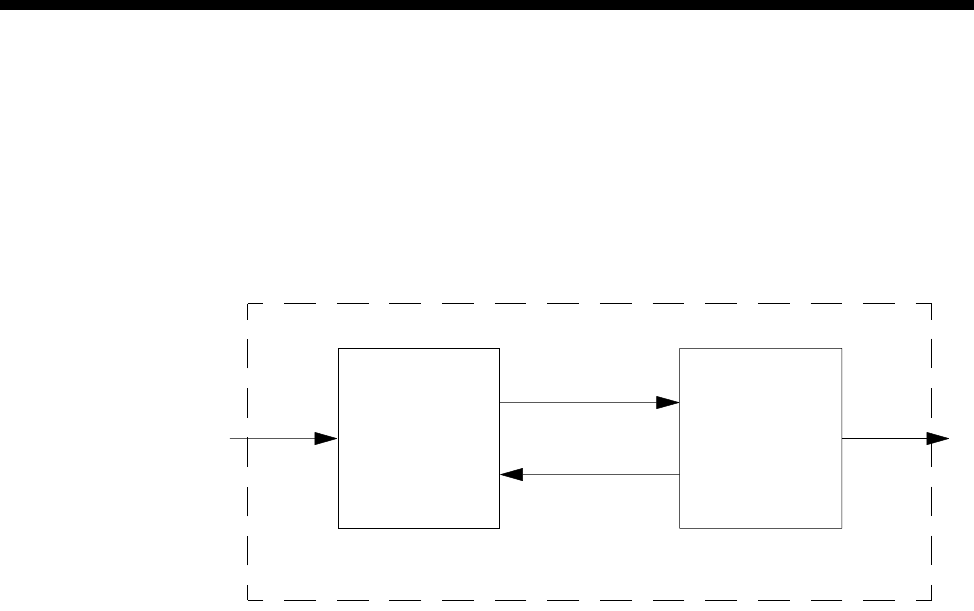
3-58 ISDN Interworking
10003497.00 Rev.5
Call connected through an Interworking Unit
Each call made through the Interworking Unit consists of two calls:
•an incoming call from one network into the device and
•a corresponding outgoing call from the device into the other network
as shown in the following diagram.
Interworking Unit
The interworking connection between Interworking Unit lines is established as a
non-volatile, bi-directional, manual connection which supports the interconnection
of B-channels and signalling channels. See Configuration below for instructions on
configuring the connection between Interworking Unit lines.
As Telstra Australia ISDN supports a wider range of call types than DMS-100, the
Interworking Unit must interconnect different call types. For example, the
Interworking Unit can route a switched call from DMS-100 to its destination via a
Telstra Australia semipermanent connection.
Each call is independent as far as B-channel and Call Reference is concerned. Two
Interworking Unit lines are required to form a connection from one ISDN interface
to another. These calls only exist between the ISDN Interface and the Connection
Termination Point (CTP).
Interworking Unit line
This is an element in the Control Module or Resource Manager which you can
configure to terminate a connection from an ISDN interface. Each Interworking Unit
line can:
•have a direct line number, or
•be part of a lineset with a range of numbers
•be used for bi-directional calls (incoming and outgoing).
To make Interworking transparent, place all Interworking Unit lines in a lineset with
the number range of 0000000-9999999.
Connection Connection
Transit Switch
(Incoming CTP) (Outgoing CTP)
Interworking
Connection
From IPMT-PRI To IPMT-PRA
Incoming call terminated
at CTP 1 Outgoing call initiated
by CTP 2
Termination
Point 1 Termination
Point 2

System Configuration 3-59
© 1993–2000 Jtec Pty Limited
Clocking
The DMS-100 must have the same master reference clock as the Telstra Australia
ISDN. You can configure a device to derive its clock from either the PRA IPMT or the
PRI IPMT.
If you configure a device to derive its clock from the PRA, the DMS-100 can derive
its clock from the PRI. If there is no valid clock source the device sends an alarm to
OmniVision.
The device attempts to obtain its reference clock from the most reliable source
available. The possible sources are the ISDN or the leased line provider.
If no reference clock source is available, the modules operate off a locally generated
clock according to the following priority list:
•ISDN PRA TE modules
•ISDN PRA NT and E1M modules
•ISDN BRA TE modules.
The reference clock master changes if the current master fails to sense network clock
or if a module with a higher priority senses network clock. See Reference Master
Priorities on page 3-49 for more information.
You can exclude modules from selection as reference clock providers through
OmniVision.
For more examples of the Interworking facility see page 5-34 of the Applications
section.
Operation
Incoming calls
An incoming call is directed to the incoming Interworking Unit line which matches
the called number or semipermanent label. The incoming Interworking Unit line
passes the complete number (with indial digits suppressed if required) as well as the
Calling Line Identification to the outgoing Interworking Unit line.
For a switched call, the dialled number is passed en-bloc across the interworking
connection. For a semipermanent connection with end-to-end signalling, the digits
are passed as they are received to enable overlap dialling.

3-60 ISDN Interworking
10003497.00 Rev.5
Outgoing Calls
When the outgoing Interworking Unit line is notified of a call by the incoming
Interworking Unit line, it makes an outgoing call based on its Call Establishment
Modes settings. The call can be made to either:
•a Hotline number, if one is configured
•the number passed to the outgoing Interworking Unit line (with any indial
modifications) from the incoming Interworking Unit line, or
•a combination of both, where the Hotline number is sent en-bloc followed by the
indial digits.
Call types
ISDN Interworking supports the following call types.
On both the PRA and PRI sides:
•Switched call
•Long held switched call (Timelink — Australia only)
•SPC (where available)
•SPC with end-to-end signalling (IDAS) (where available)
•XSPC
•XSPC with end-to-end signalling (IDAS).
Between PRA and PRI:
A range of combinations of the above call types are possible.
Voice Compression
You can use voice compression on the PRA side as long as calls are made to, or
received from, another Jtec device.
Supplementary services
The following supplementary services are available.
On the PRA side:
•Calling Line Identification.
On the PRI side:
•Calling Line Identification.
Between PRA and PRI:
•Calling Line Identification is carried transparently across the Interworking Unit.

System Configuration 3-61
© 1993–2000 Jtec Pty Limited
Configuration
Introduction
The following configuration instructions are based on the application diagram on
page 3-57. It assumes that the PRI is physically connected to one IPMT and the PRA
to another. As a convention (which can be adapted to suit the application’s physical
implementation) the IPMTs are referred to as L (left) and R (right) which describes
their location in the subrack and the OmniVision screen display.
The Interworking Unit lines are logically and physically located on the Control
Module or Resource Manager but are connected to each of the IPMTs via the internal
buses.
Control Module/Resource Manager
ISDN Interwork Unit Configuration
The incoming call’s calling party number and called party number, as well as any
information elements you set for the incoming Interworking Unit lines, are passed
through the interwork connection to the outgoing CTP. The outgoing CTP then sends
them out with the call. They take precedence over any existing outgoing call settings
for the outgoing Interworking Unit lines.
Selected Interwork Unit Configuration defaults
Select Outgoing TE
for this Interwork Any.
Changing Selected Interwork Unit Configuration defaults
Select Outgoing TE
for this Interwork Select the required TE. If you select Preferred or Exclusive, you must then select the
TE from the displayed list.
Common Config This option allows you to select from a subset of Call Establishment Modes and Bearer
Capability for all Interwork lines. You can select both the left and right hand sides of
the Interwork Unit. These options are explained in the Parameters chapter, except for
the following parameters which are explained on page 3-63:
•Transparent signalling
•Prog change
•Brick Wall
•DPNSS E2E.
Configure Interwork Lines (L + R)
Line Number Enter the line number assigned to this Connection Termination Point.
For outgoing calls, or if the line is a member of a lineset, this parameter can be left
blank.
Subaddress Enter the subaddress if required. It is not mandatory to enter anything in this
parameter.
Port ID Enter the Port ID if required. It is not mandatory to enter anything in this parameter.
Port Name Enter the Port Name if required. It is not mandatory to enter anything in this
parameter.

3-62 ISDN Interworking
10003497.00 Rev.5
ISDN Interface — Bearer Capability
The settings for these parameters determine the bearer transfer characteristics of the
ISDN for outgoing calls. The following table shows the default settings.
Bearer Capability defaults
ISDN Interface — Low Layer Compatibility
The settings for these parameters are determined by the capability of the equipment
used. The defaults are enabled for incoming calls and disabled for outgoing calls. For
further information about the default settings, refer to page 2-7 of the Parameters
section of this manual.
ISDN Interface — High Layer Compatibility
These parameters are not normally used. Refer to page 2-10 of the Parameters section
of this manual for further information.
Parameter Default
Octet 3 Standard CCITT (ITU-T)
Transfer Unrest.Digital

System Configuration 3-63
© 1993–2000 Jtec Pty Limited
ISDN Interface — Call Establishment Modes
The following table shows the Call Establishment Modes defaults.
Call Establishment Modes defaults
Changing Call Establishment Modes defaults
The settings for these parameters control the way in which calls are made. You can
change the following settings to meet your requirements.
Semipermanent
(where available) Enter the semipermanent number in the Label parameter and select Enable.
Parameter Default
Semipermanent
(where available) Enable Cleared
Label —
Hotline Enable Cleared
Number —
XSPC Cleared
Subaddress —
DDI (Indial) Enable Selected
Ignore first 0 digits
If Channel is Subrate,
It's Voice (use compander)
Data (use Subrate switch)
Selected
Cleared
Signalling National Significant Remote
Number
—
End-to-End Cleared
E2E service tones Cleared
Call Control Auto Answer Cleared
Callback Orig (RM only) Cleared
Callback Dest (RM only) Cleared
CBack Hotline (RM only) Cleared
Advanced Transparent signalling Cleared
Prog change Cleared
Brick Wall Cleared

3-64 ISDN Interworking
10003497.00 Rev.5
Hotline Enter the Hotline number and the subaddress number, if required, and select Enable.
Outgoing calls using this outgoing Interworking Unit line are directed to the Hotline
number.
You can also select XSPC to enable a Switched Semipermanent Connection. This is
only available if Hotline is enabled.
Note When a RHS Interworking Unit has Transparent Signalling enabled, the number
dialled into the IWU is not prefixed with the Hotline number of the LHS of the Interworking
Unit. If you require number prefixing, use the CLI/Number Checking feature.
DDI (Indial) Select Enable and enter the number of digits to be ignored. For example, if the call is
for extension 23 of the telephone number 8096923, the number of digits to ignore is
five. The Indial setting for the incoming Interworking Unit line is passed across the
interwork connection and used by the outgoing Interworking Unit line for the
outgoing call.
If Channel is
Subrate, It’sSelect data if the channel is being used for framed data rather than A-law voice.
Signalling Enter the National Significant Remote Number in the number parameter for
end-to-end signalling applications, if required.
End-to-End Enable this where the line is to be used in equipment tie line applications.
E2E service
tones Enable this to provide service tones from the incoming IWU of this VX. This is useful
where the network or the originating device cannot generate tones. When enabled,
the incoming IWU detects a call and provides the corresponding service tones.
Auto Answer Select this to connect the incoming call to the line as soon as it is received, irrespective
of the signalling state of the connected equipment.
When a tie line has end-to-end enabled, select Auto Answer to connect the end-to-end
tie line call request rather than returning the connected equipment’s signalling
indications.
Callback Orig Used for the CallBack feature. You should enable this for the end of the network that
is to accept all call charging. For more details see the CallBack feature in Interworking
applications on page 5-39.
Callback Dest Used for the CallBack feature. You should enable this at the end of the network that
is not to receive call charging. For more details see the CallBack feature in Interworking
applications on page 5-39.
CBack Hotline Used for the CallBack feature. You can enable this to force the CallBack Orig end to
use the number entered in the Hotline Number of this dialog for CallBack. This is
instead of using the CLI of the CallBack Dest end. For more details see the CallBack
feature in Interworking applications on page 5-39.
Transparent
signalling Select this option to have full Q.931 messages passed end-to-end within the user
information packets. Note that 'End to End Signalling' must be selected for this to
work.
Prog change Select if you want Alerting messages changed to Progress messages.
This can be used when a standard telephone call is diverted to a mobile network.
When the mobile phone is out of the operation area or is turned off, a verbal Alerting
Message is sent. This Alerting message is read as a ring tone by the ISDN. When Prog
change is enabled, the Alerting message is changed to a verbal Progress message.
RM
RM
RM

System Configuration 3-65
© 1993–2000 Jtec Pty Limited
Brick Wall Enable this to allow the Bearer Capability, High Layer Compatibility and Low Layer
Compatibility information elements of the incoming call to be replaced with those
set up in the outgoing IWU. The Called Party Number and subaddress are replaced
if they are set on the outgoing IWU. The Calling Party Number and subaddress are
not changed.
ISDN Interface — ISDN Line Controls
The following table shows the ISDN Line Controls defaults.
ISDN Line Controls
Changing ISDN Line Controls defaults
AOC
(where available) Select either Continuous or End to log the cost of each call from this line. You can
view the cost details via the Call Log. For further details, refer to the OmniVision User
Manual.
This is only available if you subscribe to an AOC service.
Calling Line ID Do not select CLIP (CLI Presentation).
If you select CLIR (CLI Restriction), calls from this line do the opposite of the site
default. For example, if your site default presents CLI for outgoing calls and you
select CLIR, calls from this line do not present CLI to the called party.
CLIVE List
Assignment Select this option to apply a CLI list to this line. See page 3-80 for more information.
Numbering
format Select the appropriate CCITT (ITU-T) standard for Line Number, Hotline Number,
and Line and Hotline Subaddress formats.
ISDN Interface
ISDN Interface defaults
Teleservice None
ISDN Internal Control
ISDN Internal Control defaults
Restriction None
Parameter Default
AOC
(where available) None Selected
Continuous or End of Call Cleared
Calling Line ID CLIP Cleared
CLIR Cleared
Numbering format Line No E164
Hotline E164
Line and Hotline Subaddress NSAP
CLIVE List
Assignment This line checks —
Available CLI lists —

3-66 ISDN Interworking
10003497.00 Rev.5
Changing ISDN Internal Control defaults
Restriction Select Disable to put the line into a fault state so that it is not used by the device.
Configuration of IPMT for Interworking
IPMT
Refer to IPMT on page 4-3 of the Module Configuration section of this manual for basic
configuration instructions. The configuration instructions for the interworking
options are shown below.
Options
Disable T309 Select to disable T309.
Enable CRC-4 Select to enable CRC-4. You must select this for a PRI IPMT.
Do not use as
reference clock Select to disable reference clock.
The setting you select for this parameter depends upon the clocking requirements
for each application. Refer to Clocking on page 3-59 for further information.

System Configuration 3-67
© 1993–2000 Jtec Pty Limited
MicropleX switching
Introduction
The VX can be used to provide static subchannel multiplexing. Since no switching is
performed, lines always connect to other lines as defined in a Virtual Line
configuration. This configuration can be extended to provide both point-to-point and
transit connections – again the connections are static.
Where switching is required, the calls have to be delivered to separate switching
equipment, such as a PABX, or to another device, and then back again to the
originating device. The switched application therefore requires additional equipment
and, in the case of voice services, adds additional decompression and compression
stages.
MicropleX switching allows switching onto Virtual Lines to be performed within a
single VX. A new type of subchannel line is configured which is not connected to any
physical port. This line can be configured to be Subrate voice or Subrate data. In the
case of voice, an LDCM or COMBO compander is used to connect the port. For data,
an SRMM Subrate switch is used. This new line can have calls directed to it, using
the normal call routing techniques such as matching line numbers and/or linesets.
This different form of Subrate line is obtained by combining the Interwork and the
Network Simulation Task (NeST) functions. The NeST performs the number analysis
and local switching for the VX. See ISDN Interworking on page 3-57 for details of the
Interwork function. The basic configuration unit used to implement this application
consists of pairs of interwork unit lines, a Subrate Virtual Line and a Lineset. This
functional block is represented by the figure below:
Lineset
Virtual Line
Interwork Unit
RM CM
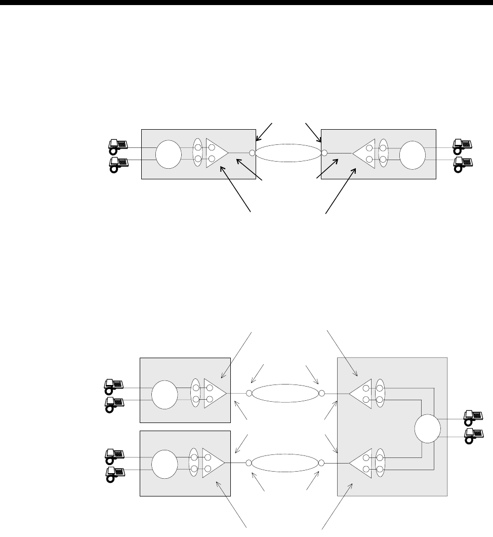
3-68 MicropleX switching
10003497.00 Rev.5
An NT line such as an ALEM, ALEM-2, COMBO ALIM or E1MN can dial a number
which matches the Lineset number range of the left side of the interwork unit lines.
The call is switched by the NeST. For a point-to-point application, this functional
block is configured as illustrated below.
In the switched application, telephones A and B can connect to either telephones C
or D.
This switching scheme can be extended past the point-to-point case using a tandem
switch configuration in the transit nodes. The tandem configuration is illustrated
below:
Calls entering the transit node can be switched to a destination line within the transit
node or be switched through the transit node toward another node. In this application
any phone can call any other one.
For more information on MicropleX Switching applications see page 5-27 of the
Applications section.
TE B-channels
SPC/XSPC
Virtual lines
ISDN NeST
NeST
Node
Node
AC
D
B
TE B-channels
TE B-channels
SPC/XSPC
Virtual lines
Virtual lines
ISDN
ISDN
NeST
NeST
NeST
Node
Node
Transit node

System Configuration 3-69
© 1993–2000 Jtec Pty Limited
Configuration
Introduction
The different operational modes of the Subrate circuits each require different
configurations on the interwork unit lines, the Virtual Lines and possibly the Linesets.
The possible operational modes are:
•tie line using XSPC
•manual connection
•demand established circuits
•tie line using SPC (where available).
Each of these operational modes can use B- or D-channel signalling.
The following sections describe the basic configuration for each of these
combinations. In these configurations, it is assumed that the left side of the interwork
unit is assigned to a lineset and the right side is assigned to a Virtual Line. This is not
essential, but is used here for consistency. Also the configuration for a single
interwork unit pair will be given, since the configuration of other interworks which
are members of the Virtual Line will be identical.
Additionally, the following items must be configured for correct operation of the
device:
•TE modules Group Number and National Significant Area Code
•Control Module or Resource Manager Access Number
•VX ‘Minimum number in this device’, ‘Maximum number in this device’ and
‘Area code without leading zero’. See page 3-17 for details on these VX settings.
XSPC operation
Lineset configuration
Configure as Non-local linesets with the following default settings:
Call delivery and
line member list
attributes
Select Linear Hunting (keep list static).
Action when call
cannot be
delivered...
Select Return cause of ‘No circuit/channel available’ to allow fallback TE & NT
resubmission.
Refer to page 3-46 for further information on configuring Linesets.
Interworking Unit left side configuration
This remains at the default settings. See ISDN Interworking on page 3-57 for further
information.

3-70 MicropleX switching
10003497.00 Rev.5
Interworking Unit right side configuration
Call establishment
modes Select SPC/Virtual Line/Manually connected.
Select Indial.
Select End to end signalling.
Select Transparent signalling mode.
Bearer Capability Select All 64K Digital.
See ISDN Interworking on page 3-57 for further information.
Virtual line configuration — B-channel signalling
Hotline Enable XSPC at one end only, if using a point-to-point connection.
Outgoing TE Select as Preferred or Exclusive on the Virtual Line with XSPC enabled. This prevents
the B-channel call from being delivered to the interwork unit.
Virtual line
Hotline number The number defined for the Virtual Line Hotline number must be entered as the line
number in the remote end Virtual Line.
Enter the number defined for the Virtual Line Hotline number in the Router table
with a SAM B-channel selected as the primary route.
SAM B-channel Configure as a member of the Virtual Line.
Semipermanent Enable semipermanent for the SAM B-channel used for the B-channel Signalling.
Virtual line configuration — D-channel signalling (where available)
Hotline Enable XSPC at one end only, if using a point-to-point connection.
Outgoing TE Select as Preferred or Exclusive on the Virtual Line with XSPC enabled. This prevents
the B-channel call from being delivered to the interwork unit.
Virtual line
Hotline number The number defined for the Virtual line Hotline number must be entered as the line
number in the remote end Virtual Line.
Manual Connection operation
Lineset configuration
Configure as Non-local linesets with the following default settings:
Call delivery and
line member list
attributes
Select Linear Hunting (keep list static).
Action when call
cannot be
delivered...
Select Return cause of ‘No circuit/channel available’ to allow fallback TE & NT
resubmission.
Refer to page 3-46 for further information on configuring Linesets.
Interworking Unit left side configuration
This remains at the default settings. See ISDN Interworking on page 3-57 for further
information.

System Configuration 3-71
© 1993–2000 Jtec Pty Limited
Interworking Unit right side configuration
Call establishment
modes Select SPC/Virtual Line/Manually connected.
Select Indial.
Select End to end signalling.
Select Transparent signalling mode.
Bearer Capability Select All 64K Digital.
See ISDN Interworking on page 3-57 for further information.
Virtual line configuration — B-channel signalling
Interwork lines Enter a user-defined SPC label for those individual interwork unit lines which are
members of the Virtual Line.
Configure the Signalling—National Significant Remote Number for the individual
interwork unit lines which are members of the Virtual Line to the IPMT or BRMT
group number of the remote end TE.
Enter the number defined for the Interworking Unit Signalling—National
Significant Remote Number in the Router table, with a SAM B-channel selected as
the primary route. The Router table configuration is only required at the device with
the highest Group number.
Outgoing TE Selection for End to End Signalling must be set to Preferred or Exclusive in the
Control Module or Resource Manager dialog.
SAM B-channel Configure as a member of the Virtual Line.
Semipermanent Enable for the SAM B-channel used for the B-channel Signalling.
Virtual line configuration — D-channel signalling (where available)
Interwork lines Enter a user-defined SPC label for those individual interwork unit lines which are
members of the Virtual Line.
Configure the Signalling—National Significant Remote Number for the individual
interwork unit lines which are members of the Virtual Line to the IPMT or BRMT
group number of the remote end TE.
Enter the number defined for the Interworking Unit Signalling—National
Significant Remote Number in the Router table, with a SAM B-channel selected as
the primary route. The Router table configuration is only required at the device with
the highest Group number.
Outgoing TE Selection for End to End Signalling must be set to Preferred or Exclusive in the
Control Module or Resource Manager dialog.
Demand Established operation
Lineset configuration
Configure as Non-local linesets with the following default settings:
Call delivery and
line member list
attributes
Select Linear Hunting (keep list static).
Action when call
cannot be
delivered...
Select Return cause of ‘No circuit/channel available’ to allow fallback TE & NT
resubmission.

3-72 MicropleX switching
10003497.00 Rev.5
Refer to page 3-46 for further information on configuring Linesets.
Interworking Unit left side configuration
This remains at the default settings. See ISDN Interworking on page 3-57 for further
information.
Interworking Unit right side configuration
Call establishment
mode Select Indial.
Bearer capability Select All 64K Digital.
Virtual line configuration — B-channel signalling
The following settings apply to both ends of the point-to-point connection.
Outgoing TE Select as Preferred or Exclusive on the Virtual Line. This prevents the B-channel call
from being delivered to the interwork unit.
Virtual line
Hotline number Enter this as the line number in the remote end Virtual Line.
Enter in the Router table with a SAM B-channel selected as the primary route.
SAM B-channel Configure as a member of the Virtual Line.
Virtual line configuration — D-channel signalling (where available)
Hotline Enable.
Outgoing TE Select as Preferred or Exclusive on the Virtual Line. This prevents the B-channel call
from being delivered to the interwork unit.
Virtual line
Hotline number Enter this as the line number in the remote end Virtual Line.
SPC operation (where available)
Lineset configuration
Configure as Non-local linesets with the following default settings:
Call delivery and
line member list
attributes
Select Linear Hunting (keep list static).
Action when call
cannot be
delivered...
Select Return cause of ‘No circuit/channel available’ to allow fallback TE & NT
resubmission.
Refer to page 3-46 for further information on configuring Linesets.
Interworking Unit left side configuration
This remains at the default settings. See ISDN Interworking on page 3-57 for further
information.

System Configuration 3-73
© 1993–2000 Jtec Pty Limited
Interworking Unit right side configuration
Call establishment
modes Select SPC/Virtual Line/Manually connected.
Select Indial.
Select End to end signalling.
Select Transparent signalling mode.
Bearer Capability Select All 64K Digital.
See ISDN Interworking on page 3-57 for further information.
Virtual line configuration — B-channel signalling
Interwork lines Enter a user-defined SPC label for those individual interwork unit lines which are
members of the Virtual Line.
Configure the Signalling—National Significant Remote Number for the individual
interwork unit lines which are members of the Virtual Line to the IPMT or BRMT
group number of the remote end TE.
Enter the number defined for the Interworking Unit Signalling—National
Significant Remote Number in the Router table, with a SAM B-channel selected as
the primary route. The Router table configuration is only required at the device with
the highest Group number.
Outgoing TE Set End to End Signalling to Preferred or Exclusive in the Control Module or
Resource Manager dialog.
SAM B-channel Configure as a member of the Virtual Line.
Semipermanent Enable for the SAM B-channel used for the B-channel Signalling.
Virtual line configuration — D-channel signalling
Interwork lines Enter a user-defined SPC label for those individual interwork unit lines which are
members of the Virtual Line.
Configure the Signalling—National Significant Remote Number for the individual
interwork unit lines which are members of the Virtual Line to the IPMT or BRMT
group number of the remote end TE.
Enter the number defined for the Interworking Unit Signalling—National
Significant Remote Number in the Router table, with a SAM B-channel selected as
the primary route. The Router table configuration is only required at the device with
the highest Group number.
Outgoing TE Selection for End to End Signalling must be set to Preferred or Exclusive in the
Control Module or Resource Manager dialog.

3-74 Inband signalling facility
10003497.00 Rev.5
Inband signalling facility
Introduction
Inband Signalling provides an alternative to the ISDN D-channel user-to-user
messaging service (but it does not preclude its use). It is useful where this service is
unavailable or uneconomical.
The Inband Signalling function is provided by either the Control Module (CM),
Resource Manager (RM) or the Signalling Access Module (SAM), all of which can
function as network nodes. Each node contains a router and communications links.
The interface on the SAM is synchronous V.24 DTE at rates up to 38.4 kbit/s.
An inband connection consists of one or more communications links and transit
routers. As Control Modules or Resource Managers cannot be linked together for
networking purposes, you require a DLM with V.24 DCE interface or a SAM with
V.24 DCE interface to build a network.
You can use one or more routers and communications links to create a network of
VXs to transport network management and end-to-end tieline signalling
(UDAS/IDAS) information.
For examples of how to apply Inband signalling in different scenarios see the
Applications section page 5-43.
Routers
Each Signalling Access Module, Control Module or Resource Manager contains a
router. A router provides a routing table which defines:
•an address (phone number) or range of addresses
•the port for the primary route
•the port for the secondary route.
To establish a network management or end-to-end signalling call, a path must be
connected through a series of one or more routers. Each one makes a connection with
the next until the call reaches its destination.
Routers establish B-channel and D-channel calls as required for each end-to-end
connection. You can configure the router ports and tables to define every required
path. Each path may involve several links and routers.
Router Ports
Control Module/Resource Manager
For Inband Signalling the CM supports up to 16 D-channel ports.
The RM supports one dedicated 8 kbit/s port on the backplane and up to 16 other
ports configured as either 8 kbit/s backplane ports or D-channel ports.
RM CM

System Configuration 3-75
© 1993–2000 Jtec Pty Limited
SAM
For Inband Signalling, SAM provides:
•backplane ports which can be configured as either:
•eight 8 kbit/s ports
•four 8 kbit/s ports and one 64 kbit/s port
•two 64 kbit/s ports
•one front panel port which can be either X.21, V.35 or synchronous V.24 and can
be configured as either a DCE or DTE.
SDLMs
You can also use a V.24, V.35 or X.21 SDLM to provide extra front panel ports for an
CM, RM or SAM router.
Connecting Router Ports
Router Ports are connected to create communications links. You can connect:
•two front panel ports using a cable
•two backplane ports (in the same chassis) using an OmniVision manual
connection
•two backplane ports via the ISDN B-channel (either dedicated or Subrate
multiplexed)
•a backplane port to a front panel port via an SDLM. (To do this, you connect the
backplane port to the backplane of the SDLM via an OmniVision manual
connection. Then use a cable to connect the SDLM front panel port to the front
panel router port.)
•two D-channel ports via an ISDN D-channel.
When connecting front panel ports you must ensure that one is a DTE and the other
a DCE. However, this is not necessary for a connection between two D-channel ports
or backplane ports. Connected backplane ports must also be configured for the same
data rates.
Call routing and connection
To establish a network management or end-to-end signalling call a path must be
connected through one or more routers.
When a router receives a call setup it attempts to match the called party number with
an address in its routing table. If the matching port has no physical connection to the
next router, an ISDN B-channel or D-channel call is made to the Hotline number
configured for the router port.
Sharing an existing connection
After a connection has been established for one call, other calls requiring the same
connection can share it. Even if the other connection only requires some of an
established connection the common links can be shared thereby reducing
communications costs.

3-76 Inband signalling facility
10003497.00 Rev.5
Backup routes
If a connection which forms part of the primary route fails, the secondary route is
used. If this also fails an alarm is generated.
Signalling end-points
When Inband Signalling is used for network management the end points can be:
•OmniVision — (connected to the front panel of the Control Module or Resource
Manager)
•a Network Management System (NMS) connected to any front panel port
•the Control Module or Resource Manager.
When Inband Signalling is used for end-to-end tie line signalling the end-points are
ALEM, ALEM-2, ALPM, ALPM-2, COMBO ALIM, EMM or E1M lines. They are all
connected to the router in the CM or RM via a router port.
End-point addressing
Every end-point has a unique address (phone number). When a router receives an
incoming call setup from another router, it attempts to match the called party number
with an end-point in its router table. If a match is found it connects the call to the
router port for that end-point.
Networks
You can use routers and communications links to design a management/signalling
network. The front panel connectors must be of the same interface type and
configured correctly. That is, for each pair, one must be a DTE and the other a DCE.
You can design a number of different types of networks, including:
•Point-to-point
•Two devices connected via the ISDN
•Star.
A Signalling Access Module in one chassis can be connected with up to eight other
devices.
For examples of how to apply Inband Signalling in different scenarios see the
Applications section page 5-43.
Configuration
This section provides some basic guidelines for configuring Signalling Access
Modules, the Control Module and Resource Manager for Inband Signalling.
To build a private network, you must first set up routing tables for each router.

System Configuration 3-77
© 1993–2000 Jtec Pty Limited
Configuring the Control Module or Resource Manager
Signalling Access (CM/RM-SAM)
SAM Line Control
Edit Line Select the required line. Choose either the B or D button to convert one of the 16
configurable SAM channels to B- or D-channel.
Note The CM only supports D-Channels.
Configure
Router tables Enables you to set up an Inband Signalling network.
Note The RM-SAM can contain up to a total of 256 entries in its router table. The number
of router table entries that can point to a single SAM B-channel or D-channel is limited only
by the maximum number of entries in the router table.
Inband Signalling Routing Table
Destination Address
Min/only Enter the number or the minimum number for a range.
Max Enter the maximum number for a range.
SAM channel idle holding time
This has a range from 0 to 2550 secs. The default is 30 secs. When enabled, the channel
is held open for the specified time even when no activity is detected.
Area code
Enter the Area Code without the Escape Prefix (normally the leading zero).
ISDN Interface — Low Layer Compatibility and Bearer Capability
The default values for Low Layer Compatibility are such that LLC is not applied to
outgoing calls, and the Bearer Capability is set to Unrestricted Digital.
Note If you are downloading a configuration from an earlier release, you must change these
parameters to suit the latest defaults.

3-78 Inband signalling facility
10003497.00 Rev.5
ISDN Interface — Call Establishment Modes
The following table shows Call Establishment Modes default settings for each
channel.
Changing Call Establishment Modes defaults
The settings for these parameters control the way in which calls are made. You can
configure the following call types:
Semipermanent
(where available) Enter the semipermanent number in the Label parameter and select Enable. You
should also clear the Hotline checkbox.
Hotline Enter the Hotline number for the channel and enter a subaddress, if required. Select
Enable. You should also clear the Semipermanent checkbox.
Select XSPC to enable a switched semipermanent connection if required. You can only
select this if a Hotline is enabled.
Configuring a SAM
SAM Line Control
Edit Line Select the required line.
Configure
Router tables Enables you to set up an Inband Signalling network.
Configure Inband Signalling Routing Table
Min/only Enter the number or the minimum number for a range.
Max Enter the maximum number for a range.
Parameter Default
Semipermanent
(where available) Enable Cleared
Label —
Hotline Enable Cleared
Number —
XSPC Cleared
Subaddress —
Call Control ——

System Configuration 3-79
© 1993–2000 Jtec Pty Limited
ISDN Interface — Call Establishment Modes
The following table shows Call Establishment Modes default settings for each
channel.
Changing Call Establishment Modes defaults
The settings for these parameters control the way in which calls are made. You can
configure the following call types:
Semipermanent
(where available) Enter the semipermanent number in the Label parameter and select Enable. You
should also clear the Hotline checkbox.
Hotline Enter the Hotline number for the channel and enter a subaddress, if required. Select
Enable. You should also clear the Semipermanent checkbox.
Select XSPC to enable a switched semipermanent connection if required. You can only
select this if a Hotline is enabled.
ISDN Internal Control
Restriction None.
Operation (Front
panel only) Select DCE or DTE.
Use Q.931 protocol
(D-channel only) This is the default.
Use X.25 protocol
(D-channel only) Select to use the X.25 protocol.
Send Acknowledge
message (D-channel
only)
When enabled every message sent on this line will be responded to with an
acknowledge message. This should normally be disabled to obtain a higher data
throughput. Both ends of the link should have the same setting.
Enable protocol
discriminator
(D-channel only)
When enabled a protocol discriminator with the value of 00 is added to all messages.
This is required when calls are made via networks which check the protocol
discriminator value. Both ends of the link should have the same setting.
Outgoing TE Select the required TE. If you select Preferred or Exclusive, you must then select the
TE from the displayed list. This setting affects all the module’s lines.
Parameter Default
Semipermanent
(where available) Enable Cleared
Label —
Hotline Enable Cleared
Number —
XSPC Cleared
Subaddress —
Call Control ——

3-80 Calling Line Identification and Verification Enhancement
10003497.00 Rev.5
Calling Line Identification and Verification Enhancement
Calling Line Identification and Verification Enhancement (CLIVE) enables the device
to:
•accept or reject calls based on the CLI/Number
•modify accepted calling and/or called party identification.
CLI/number checking
Calls are accepted or rejected on the basis of the calling or called party’s number which
is provided by the ISDN with each call. This is checked against CLI/Number
Checking lists which you set up.
CLI/Number checking is available for incoming and outgoing calls from the ISDN.
If the call is accepted the number can be modified in a variety of ways. For example,
it can be replaced with another number or it can have a prefix or suffix added to it.
CLI/Number checking is always active. Its effect on the operation of the device is
mediated by the Available CLI/Number list.
Its main features are:
•A maximum of 254 CLI/Number Checking Lists
•A List can be applied to all Lines
•A line can have up to 20 CLI/Number Checking Lists applied to it.
Calling Party Number
The Calling Party Number is provided by the ISDN on incoming calls. As it is a
network specific application, its format and provision depends upon the network. In
Australia, the Calling Party Number is provided on all ISDN calls unless the caller
subscribes to Calling Line Identification Restriction (CLIR) and specifically requests
that the number be suppressed.
The number is verified and inserted by the exchange if the caller omits it or provides
an incorrect number.
The Calling Party Number is always restricted if the call does not originate in the
ISDN, unless the ISDN service is a special provision.
CLI/Number lists
A CLI/Number list contains sets of Calling Party Numbers against which incoming
calls are checked.
You can create and manipulate up to 254 CLI/Number lists and apply these lists to
selected lines. There is no limit to the number of lines a list can be applied to. You can
choose to accept or reject calls from numbers that match those contained in the lists.
RM CM

System Configuration 3-81
© 1993–2000 Jtec Pty Limited
Each CLI/Number list contains a particular group of calling party numbers. For
example, one list may contain all the Sydney telephone numbers and another list may
contain the telephone numbers of members of a special group, such as all the board
members of a particular company.
CLI/Number lists may be:
•global
This list effects all lines in the device and is always called Global. You should take
care when creating a global list to ensure that calls are not mistakenly rejected.
•specific
These lists can be applied to individual lines, individual modules or linesets. You
provide a descriptive name for each list you create.
How CLI/Number checking works
CLI/Number checking is always active. Its effect on the operation of the device is
determined by the contents of the global and specific CLI/Number lists and the way
in which the specific lists are applied to lines. If no global or specific CLI/Number
list is present, all calls are accepted.
If a global CLI/Number list is present, it is always checked for the calling party
number first. If the number is found and the call is accepted, any specific
CLI/Number lists are then checked, in the order in which they were applied to the
line.
If the number is found in a CLI/Number list, the call will be either accepted or
rejected, as specified by the list. If none of the specific CLI/Number lists contain the
calling party number, the call will be rejected. If the Calling Party Number is not
present, the call will be rejected by CLI/Number lists which accept a range.
A flexible combination of selective number manipulation, selective rejection and
'accept the rest' processing can be applied to calls by sequential application of several
list types.
Warning You must take particular care when using CLI/Number checking to reject calls. After
defining and applying the list(s) of calling party numbers to be rejected, you should
define a CLI/Number list which accepts every possible calling party. Add it after the
other CLI/Number lists associated with the line. If you do not do this, every call will
be rejected, not just those which you have explicitly defined.

3-82 Calling Line Identification and Verification Enhancement
10003497.00 Rev.5
Checking the Calling Party Number in an ’Accept Only’ List
When number checking the calling party number in an ’accept only’ list, all call
matches against a list are accepted, whilst those with no match are checked against
each of the next lists in order until all lists are checked. An accepted call will undergo
designated calling or called number manipulation before forward call processing. If
no match is found to any list the call will be rejected. To be able to accept calls in this
case, another number checking list must be created which will accept all calls that fall
within the required number range. This catch-all list is often referred to as a ’bucket’,
with the bucket being the last list applied to a line. The list application order is
important in this case as this must be the last list applied.
Checking the Calling Party Number in a ’Reject Any’ List
When number checking the Calling Party Number in a ’Reject Any’ list, all call
matches to a list are rejected immediately, whilst those with no match are checked
against each of the next lists in order until all lists are checked. If no match is found
to any list the call will be rejected. To be able to accept calls in this case, a “bucket”
must be applied as the last list to a line.
Checking the Called Party Number in an ’Accept Only’ List
When number checking the called party number in an 'accept only' list, all calls with
matched numbers will undergo the designated calling or called number
manipulation before further forward call processing. Lists are checked in order until
a match is made. If the called party number is not matched to any list, the call will be
forward call processed in the normal manner.
Note A ’bucket’ is not required to prevent calls from being rejected following failure to
match against an ’Accept Only’ list. As called party number matching is used predominantly
for number changing rather than number checking, the ’always accept’ default for unmatched
calls is the most desirable operational characteristic for this type of list.
Checking the Called Party Number in a ’Reject Any’ List
When number checking the called party in a 'Reject Any' list, all call matches to a list
are rejected immediately, whilst those with no match are checked against each of the
next lists in order until all lists are checked. If no match is found to any list the call
will be forward call processed in the normal manner.
Configuration
To configure CLIVE, use Number Checking in OmniVision. You can then:
•define CLI/Number lists
•apply them to specific lines as required
•specify any modifications to the called party number.

System Configuration 3-83
© 1993–2000 Jtec Pty Limited
Parameters
CLI/Number Checking
CLI/Number List
Name Select Global or enter a unique descriptive name for the list.
ID Number Displays the identification number for the selected CLI/Number list.
Type Displays the list type for the selected CLI/Number list.
Numbers Displays the number(s) and/or range(s) for the selected CLI/Number list.
CLI/Number Checking — Configure
Apply Select to apply the selected CLI/Number list to lines, modules or linesets.
Numbers Select to enter the number or range of numbers to be checked.
New List Select to create a new CLI/Number list.
Remove List Select to remove the selected CLI/Number list.
CLI/Number Checking List — How to Apply This List
Accept Only
Numbers in List This is the default. Accept it to specify that calls from numbers in this list will be
accepted.
Reject Any
Numbers in List Select to specify that calls from numbers in this list will be rejected.
CLI/Number Checking List — Apply to
Calling party
number Select to apply the list to the calling party number.
Called party
number Select to apply list to called party number.
CLI/Number Checking List — What To Do With Accepted Calls
Pass on Directly Select to pass the call on without modification.
Modify Called
Number Select to pass the call on with one of the following modifications. This is the default.
Modify Calling
Number Select to pass the call on with one of the following modifications.
Modifier Enter the modifier number (up to 10 digits). It can be a complete number, a prefix or
a suffix.
Replace With Select to replace the called party number with the modifier number displayed.
Prefix With Select to insert the modifier digits before the called party number as a prefix.
Suffix With Select to insert the modifier digits after the called party number as a suffix.
Add Select to add, numerically, the modifier to the called party number.
Subtract Select to subtract, numerically, the modifier from the called party number.
Replace with
Number Select to replace the called party number with the calling party number.
Number Prefixed
With Select to replace the called party number with the calling party number and modifier
as a prefix.
Number Suffixed
With Select to replace the called party number with the calling party number and modifier
as a suffix.

3-84 Calling Line Identification and Verification Enhancement
10003497.00 Rev.5
Number With
Added Select to replace the called party number with the calling party number numerically
added to the modifier.
Number With
Subtracted Select to replace the called party number with the calling party number with the
modifier numerically subtracted from it.
CLI Number Checking List - Apply When Line Is
Call Destination Select to apply Number Checking at the Call Destination, that is, check the number
after call processing and optionally change the Calling or Called number.
Call Source Select to apply Number Checking at the Call source, that is, check the number before
processing and optionally change the Calling or Called number.
Feature Trans. Select when applying public network number mapping to DPNSS or QSIG for
supplementary service handling. This prevents a problem on some networks where
calls from the DPNSS or QSIG module to the PBX undergo a number change on the
way out due to standard number changing.
Release 12 This is the Default. Number Checking is only carried out at the Call Destination.
Release 12 and earlier software only supports this form of number checking.
Called Number =
<CALLED> Displays the called party number format, resulting from the specified modification.
Min/Only Enter the number or minimum number of the range for this CLI/Number list to
check. Both the Min/Only and Max field accept a wildcard character of ?. For
example, to check all the numbers in a range 1090 to 1099, you could specify a
Min/Only number of 109? to check all of these numbers.
Max Enter the maximum number of the range for this CLI/Number list to check.
List Name Displays the name of the selected CLI/Number list. You can change it if required.
Add Number Select to add the number in the Min/Only field to the list of numbers checked by this
CLI/Number list.
Add Range Select to add the range in the Max and Min fields to the list of numbers checked by
this CLI/Number list.
Delete Select to delete the selected number or range from the list of numbers to be checked
by this CLI/Number list.
Delete All Select to delete all the numbers or ranges from the list of numbers to be checked by
this CLI/Number list.
Import This enables you to produce a CLI/Number list in a database or spreadsheet package
and then import it into OmniVision.
Export This enables you to export a CLI/Number list from OmniVision to a database or
spreadsheet package.
Accept Call when no
CLI provided Select to accept calls when no CLI is provided, as well as those that match the
specification.
Which party to apply to
Calling party
number Select to apply list to calling party number.
Called party number Select to apply list to called party number.
Applying CLI/Number Checking
Add Select to add the selected module, line or lineset for this CLI/Number list to check.
Delete Select to delete the selected module, line or lineset from the list for this CLI/Number
list to check.

System Configuration 3-85
© 1993–2000 Jtec Pty Limited
Applying CLI/Number Checking — List all
Modules Select to display a list of all possible modules for this CLI/Number list to check.
Lines Select to display a list of all possible lines for this CLI/Number list to check.
Linesets Select to display a list of all possible linesets for this CLI/Number list to check.
CLI/Number Checking
Add Select to add the selected CLI/Number list to the This line checks list.
Delete Select to delete the selected CLI/Number list from the This line checks list.

3-86 Serial Alarm Interface
10003497.00 Rev.5
Serial Alarm Interface
The Serial Alarm Interface provides an interface between Jtec’s Network
Management System, OmniVision, and another Network Management System,
British Telecom’s Concert. Concert complies with OSI Network Management Forum
standards. It does not manage Jtec products directly but manages them through their
own element manager, in Jtec’s case, OmniVision.
The Serial Alarm Interface enables OmniVision to:
•report Alarm information to Concert via OmniVision’s Serial Alarm Log
•send an information message to Concert to verify that OmniVision is working.
Information message to Concert
OmniVision can send an information message to Concert at regular intervals to
indicate that OmniVision is still working. This is sent irrespective of whether there is
Alarm information from the device. To enable this feature, follow the configuration
instructions below.
Configuration
See your OmniVision User Manual for details on accessing these parameters.
Serial Alarms On Select this to enable the interface.
Configuration of ’hello’ message
Device Enter the Device name. It can be up to 32 alphanumeric characters. This name is
displayed in the NMS_NODENAME field of the Hello Message.
Manager Enter the Manager number. It can be up to 20 digits. This number is displayed in the
NUMBER field of the Hello Message.
Enable ‘hello’
messages. Select this to enable 'hello' messages.
Interval between
’hellos’ (5 secs to 24
hrs)
Enter the required time (between 5 seconds and 24 hours) between 'hello' messages.
The default is 10 seconds.
Configuration of SPEAC
SPEAC (System Protocol for External Access and Control) is available with the
OmniVision NCS product. For more information, refer to the OmniVision User Manual.
RM CM
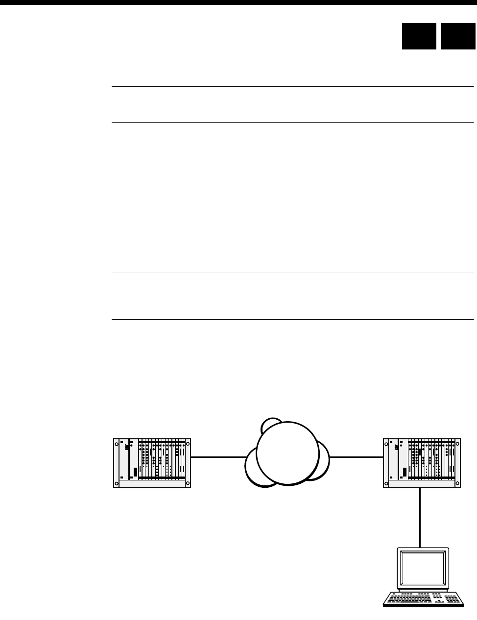
System Configuration 3-87
© 1993–2000 Jtec Pty Limited
Phone Home
Note The Phone Home feature is not available to users of OmniVision NDM and NDM-5
as it requires the use of the OmniVision Map.
The Phone Home feature is an enhancement to the existing spontaneous alarm
emission feature. It allows a central site manager to have confidence in the operational
state of a device without having to maintain a management session or poll it. Instead,
the device ’phones home’ periodically if there are no alarms to report, thus providing
a positive indication that it is operating correctly.
If the Phone Home call is made over a network which supports D-channel Message
Demand Transfer Mode, it does not need to actually connect, and no flag fall charges
are incurred.
Important If the Phone Home call is made using a B-channel, the call will connect and it
will incur a flag fall charge. We recommend that B-channels are not used for the Phone Home
feature.
Operation
The following diagram show how a Phone Home network could be constructed.
OmniVision is configured to poll the Remote Device at a fixed interval. The Remote
Device is configured to call the Local Device which is set to collect the Phone Home
messages at intervals less than that which OmniVision polls the device. The Local
Device sends the collected messages to OmniVision as they are received.
ISDN
Remote
Device
Local
Device
OmniVision
Collecting
Phone Home
Messages
RM CM

3-88 Phone Home
10003497.00 Rev.5
If the Remote Device phones home within the OmniVision poll interval, OmniVision
restarts the poll interval timer. If the Remote Device fails to phone home before the
OmniVision poll timer expires, OmniVision polls the device. If the polled session fails,
an alarm is raised for the device.
A poll interval period of five minutes longer than the Phone Home period is generally
adequate to ensure that OmniVision does not have to poll the device when it is not
required.
Note In this release, the Phone Home feature is only supported if OmniVision is connected
to the local device by a serial connection. It is not supported over a LAN connection.
Configuration
This section is based around the simple network shown in the diagram above.
Remote device
To set up the Remote Device for Phone Home:
1Select Enable Alarm Signalling in the RM Configuration dialog.
2Set the Phone Home Expiry Time.
3Enter the number of the Local Device in the To Number field. This is the device
chosen to collect the messages on behalf of the central site manager (OmniVision).
An alternative number (Alt Number) can be entered if required, as well as the
Number of retries.
Local device
The Local Device, chosen to collect the phone home messages, requires no special
configuration other than the entry of the Manager Number.
OmniVision
There are several steps for preparing OmniVision to support Phone Home. The basic
steps are detailed below. Refer to the OmniVision User Manual for more information.
1Enable Accept Automatic Alarm Sessions in Option Settings. Enter the details
of how the Local Device should be accessed. Provide an Access Number if the
device must be accessed remotely.
2 In Navigator, add the entries for the Remote Devices being monitored to the
Master List. Ensure that the Poll Time in Advanced Settings is set to an interval
larger than the Phone Home Timer in each Remote Device. Make the session
Online.

System Configuration 3-89
© 1993–2000 Jtec Pty Limited
3Create a network map using OmniVision, and add the devices being monitored
to the OmniVision Map. When adding these entries ensure that:
•the Node Name is the same as the name in the Master List
•the Net Address is the IP Address of the OmniVision station
•the SNMP Community Names accessed via the Comm... button are set to the
Node Name as they appear on the Master List.
Once the above steps are complete and the objects are functioning correctly, the Map
will display them in green. When an alarm occurs, the object changes to red. When
the alarm clears, the indicator turns to magenta. You can view the alarms using the
Alarm Log.

3-90 Phone Home
10003497.00 Rev.5

Module configuration 4-1
© 1993 - 2000 Jtec Pty Limited
4Module
configuration

4-2 Introduction
10003497.00 Rev.5
Introduction
This section provides information about each of the modules. The default settings for
the parameters for all modules are listed, together with possible changes and
configuration examples.
Note To allow for full and flexible use of ISDN facilities, each module has many parameters
and options within parameters that you can select. However, in most cases, the pre-existing
default settings are correct. These are known to work and you should use them unless you
have specific requirements and a thorough understanding of the protocols and their
configuration.
Some of the modules detailed in this section are only available to you when your
chassis is fitted with a Resource Manager (RM). The following markers are used
throughout the manual to indicate the modules supported by the Control Module,
the Resource Manager or both:
RM Feature or module supported by Resource Manager.
CM Feature or module supported by Control Module.

Module configuration 4-3
© 1993 - 2000 Jtec Pty Limited
ISDN Primary Rate TE Module (IPMT)
The ISDN Primary Rate TE Module (IPMT) is a 2.048 Mbit/s Terminal End-point (TE)
module. It allows access to 30 B-channels and one D-channel by an NT1 at the T
interface point.
The IPMT supports Dual/multiple node access. For further information on this
subject, refer to Appendix H.
Configuration
Base Number Enter the base number in local significant format (no area code).
The base number is subtracted from an incoming called party number and the call is
routed to the resulting number. It is added to the line number and the area code to
produce the calling party number on outgoing calls.
If a base number is not entered, individual line numbers should be the full local
significant number.
The base number allows lines to be accessed from different ISDN lines or multiple
ISDN modules that have different number ranges.
Group Number Enter the group number in local significant format (no area code). It is mandatory
when a semipermanent connection is used.
The group number is the main directory number within the number range allocated
by the ISDN provider. It is shown on the label of the NT1 device to which the IPMT
is connected.
CPN Prefix (UK only) Enter the prefix for the called party number. Call control prefixes the received called
party number with the number set for the CPN prefix before performing any call
routing.
National Significant
Area Code Enter the national significant area code. It is added to the calling line number for
outgoing calls and is mandatory for semipermanent connections.
The national significant area code is the area code defined by the ISDN provider,
without the leading zero.
B-channels
available Accept the default, all 30 B-channels available. You do not need to change it.
Force EnBloc
Sending
(ETSI only)
When enabled, the IPMT always sends the dialling digits to the network enbloc. The
IPMT collects digits until the Timed Dialling value expires, and then sends all the
digits. You must enable Select channel if Force EnBloc Sending is enabled.
Timed Dialling
(ETSI only) This sets the maximum interval between dialled digits (interdigit timeout period).
When the set value expires, all of the collected digits are sent to the network. This is
used in conjunction with Force EnBloc Sending, and must not be set to disabled,
when Force EnBloc Sending is enabled.
# is Sending
Complete
(ETSI only)
If you have enabled Force EnBloc Sending, this option determines the function of
the dialled hash (#). If enabled, the number collection stops when a hash is received,
and the number is sent enbloc to the network. If this option is disabled, the hash is
collected as another digit to be dialled to the network.
Disable T309 T309 is a timer. If you enable it, and a prolonged failure occurs, calls are cleared after
15 seconds. This parameter is not mandatory.
RM CM

4-4 ISDN Primary Rate TE Module (IPMT)
10003497.00 Rev.5
Enable CRC-4 Enable this if your ISDN Terminal Equipment requires a cyclic redundancy check
(CRC) to monitor the line. This enables CRC-4 error checking at Layer 1.
CRC-4 is always transmitted. If you enable this function, CRC-4 data becomes the
Layer 1 line monitoring criteria. If it is disabled, framing errors are interpreted as
Layer 1 line errors.
CRC Enable is not available for use on DASS2.
Don’t use as
reference clock Enable this if you do not want the IPMT to supply the reference clock.
Don’t use for
D-channel calls Enable this to prevent the Resource Manager or Control Module from delivering
outgoing D-channel calls through the IPMT.
Don’t use as bus
master Enable this to prevent the IPMT being selected to provide the backplane bus clock.
Prefix called number
(ROW only) Enable to change Group number to Called Party Number (CPN). See Group number
and CPN prefix above.
DMS-100 (idle fill L2) Enable this if you want to insert idle characters between messages instead of flags.
This is required when interfacing with NorTel DMS-100.
Retain Layer 2 Enable this if you want to prevent the network from deactivating the link when it is
idle. This is necessary if you want the IPMT to provide constant clock.
Unknown number
type Enable this if you want all calls leaving this port to be set to an unknown number,
regardless of the type that was set when the call was generated.
Suppress CLI Octet
3a Enable this if you want to prevent the sending of octet 3a of the Calling Party Number
(CLI) information element. This octet contains information about the presentation
and verification of the CLI. Some networks and PABXs will not recognise the calling
party number without this option set.
Restrict CLI digits to
(UK and ROW only) Enable this if you want to limit the number of digits sent in the CLI (Calling Party
Number). In the UK, the number sent as the CLI must be the same length as the
number received from the network in the Called Party Number. The number of digits
set (n), is the number of digits from the end of the line number that are sent as the CLI.
Add progress to
alerting Enable to add a progress indicator to the incoming alerting message. This is enabled
by default for DASS modules, as DASS exchanges always provide tone, but do not
support progress indicators.
Auxiliary working
(UK only) This is a special mode of operation used in the UK in which incoming calls on a
particular channel are directed to a particular destination. No called party number
information is provided in an incoming SETUP message.
If a call arrives with no called party number and the IPMT is in Auxiliary Working
mode, the device creates a called party number by adding the channel number to the
module’s Base Number. The resulting number is used to match either a line number
or a lineset range as configured by the user.
Protocol
(ETSI only) Select the required protocol from the drop-down list. The list caters for minor
differences in the ETSI protocol implementations of France and Germany.
Convert notify to
disconnect Select if phone conference units cannot clear a call. This allows the units to
DISCONNECT a call immediately, instead of waiting the 90 seconds clear time
initiated when the NOTIFY is received from the remote hang-up.
Select channel Enable to force selection of a channel for outgoing calls.
Exclusive/Pref. TE
use only Enabling this removes the module from the TE table. The TE can then only be used
for outgoing calls if the NT making the call has Outgoing TE exclusive selected.

Module configuration 4-5
© 1993 - 2000 Jtec Pty Limited
Forward Channel
selection (UK only) When channel selection is enabled for outgoing calls, channels are usually selected
in reverse order, that is, channel 30 is selected first if it is available, and channel 1 is
selected last. The channels used for auxiliary working are usually the higher
numbered channels, so to avoid choosing them unless absolutely necessary, the
selection order can be changed to begin at channel 1 and increment from there.

4-6 ISDN Primary Rate NT Module (IPMN)
10003497.00 Rev.5
ISDN Primary Rate NT Module (IPMN)
The ISDN Primary Rate Module NT (IPMN) is a network interface emulation module,
providing 30 B-channels and one D-channel. The module has a single port which
provides the physical characteristics of an NT1 at the T interface point. Other ISDN
TEs, such as other similar equipment or PABXs, may connect to this module.
Configuration
Maximum Enter the maximum number in the range for this module.
Minimum Enter the minimum number in the range for this module. (It may be the same as the
maximum number.)
Notes
•These are complete numbers; the base number is not applied.
•Configuring the maximum and minimum numbers creates a lineset within the device.
It contains the 30 B-channels and the D-channel as members.
ISDN PRA NT Line Control defaults
Outgoing TE Any.
CRC Enable Enabled.
Don’t use as bus
master Disabled.
Don’t use as
reference clock Disabled.
You do not normally need to change these parameters.
Changing ISDN PRA NT Line Control defaults
Outgoing TE Select the required TE for all the module’s lines. If you select Preferred or Exclusive,
you must then select the TE from the list of available TEs.
CRC Enable Enable this if your ISDN Terminal Equipment requires a Cyclic Redundancy Check
(CRC) to monitor the line. This enables CRC-4 error checking at Layer 1.
CRC-4 is always transmitted. If you enable this function, CRC-4 data becomes the
Layer 1 line monitoring criteria. If it is disabled, framing errors are interpreted as
Layer 1 line errors.
Don’t use as bus
master Enable this to prevent the IPMN being selected to provide the backplane bus clock.
Don’t use as
reference clock Enable this if you do not want the IPMN to supply the reference clock.
RM CM

Module configuration 4-7
© 1993 - 2000 Jtec Pty Limited
Applications...
Connected to
Select the equipment that you are connecting to from the following available
connections:
•VX IPMN
•Enbloc Receiving NT
•Overlap Receiving NT
•PBX TE or IPMT
•Custom (see below).
Custom settings
Suppress VX IE20 Select to strip from the message, any IE20s containing NETWORK IDs and PLANs
that equal 0. Information Elements with these settings are specifically internal VX IEs.
These are stripped before sending to the peer to avoid clashes of external IE20s
(Network Specific Facilities) that may be generated by some PBXs and networks.
Suppress Display IE Select to strip the DISPLAY IE before sending message to peer.
Convert
Setup_Ack->Call
Proc
Select to prevent SETUP ACKs messages being sent (this indicates that the connection
is to an enbloc receiving peer).
Strip progress
indicators Select to strip progress indicators before sending the message to peer.
Convert User NSF
(Network Specific
Facilities)
Not applicable (T1 only).
Force Enbloc
Sending Not applicable (T1 only).
Options
Idle fill Layer 2
(DMS-100) Enable if you want to insert idle characters between messages instead of flags. This
is necessary if you want the IPMN to provide a constant clock.
Channel Negotiation Enable if you want channel negotiation on incoming calls.
When this parameter is enabled, a 'preferred' channel is selected. The connected
PABX may however want to use the designated channel to set up its own outgoing
call and will require the incoming call from the device to be set up on a different
channel. In this case the PABX will attempt to negotiate the incoming call to another
channel. This feature helps to prevent calls from being rejected should a call collision
occur.
When disabled, the call from the device specifies an 'exclusive' channel, and if a
collision occurs, the incoming call is rejected.
Extend T303 to 9.5s Enable if you want to extend Timer T303 from 4 seconds to 9.5 seconds. Timer T303
supervises transmission of the Setup message. You should enable this if the
equipment connected to the IPMN cannot respond within 4 seconds.
Add progress to
alerting When enabled, a Progress Indicator No.8 is added to the Alerting message sent from
the peer.
Do not send
progress for
Cause 34
When enabled the Progress Indicator is not sent to the peer. This allows the peer to
do a resubmission.

4-8 ISDN Primary Rate NT Module (IPMN)
10003497.00 Rev.5
Resubmit on User
Busy (ETSI only) When enabled, any call rejected with the disconnect cause ’User Busy’ is translated to
a cause of ’No Circuit Channel Available’. This allows a resubmission to occur.
Convert progress to
alerting When enabled this causes alerting messages with a progress indicator sent from a
peer to be converted to a progress message.
Options (ETSI only)
Open B-Channel
early Select this to allow early connection of the B channel to the ISDN to prevent speech
clipping.
Suppress CM/RM
dial tone Select to prevent stray CM/RM dial tone being heard by the caller. Stray or delayed
CM/RM dial tone occurs when the CM or RM is operating at high load.
Number type
unknown This allows the Type Of Number field in the Called Party Number Information
Element to be forced to ’Unknown’. This may be a requirement of some PBXs and
exchanges.
Number type
subscriber This allows the Type Of Number field in the Called Party Number Information
Element to be forced to ’Subscriber’. This may be a requirement of some PBXs and
exchanges.
Indial digits
Limit DDI digits
(UK and ROW only) Enable if you want to limit the called party number to the number of digits set in ’DDI
digits to send’. Only the last n called party number digits are sent to the IPMN.
Protocol (ETSI only)
Select the required protocol from the drop-down list. The list caters for minor
differences in the ETSI protocol implementations of France and Germany.
Force EnBloc (ETSI only)
Force EnBloc
Sending When enabled, the IPMT always sends the dialling digits to the network enbloc. The
IPMN collects digits until the Timed Dialling value expires, and then sends all the
digits. You must enable Select channel if Force EnBloc Sending is enabled.
Timed Dialling This sets the maximum interval between dialled digits (interdigit timeout period).
When the set value expires, all of the collected digits are sent to the network. This is
used in conjunction with Force EnBloc Sending, and must not be set to disabled,
when Force EnBloc Sending is enabled.
# is Sending
Complete If you have enabled Force EnBloc Sending, this option determines the function of
the dialled hash (#). If enabled, the number collection stops when a hash is received,
and the number is sent enbloc to the network. If this option is disabled, the hash is
collected as another digit to be dialled to the network.
ISDN Interface — Bearer Capability
The settings for these parameters determine the bearer transfer characteristics of the
ISDN for outgoing calls.
Configure individual lines
The complete line configuration for each of the B-channels and D-channel is available
using this dialog; however, the configuration is not normally used, as the IPMN ISDN
messages are derived from those coming from the TE.

Module configuration 4-9
© 1993 - 2000 Jtec Pty Limited
ISDN Primary Rate NT Module -T1 (IPMN-T1)
The ISDN Primary Rate Module NT- T1 (IPMN-T1) is a network interface emulation
module, providing 23 B-channels and one D-channel. The module has a single port
which provides the physical characteristics of an NT1 at the T interface point. Other
ISDN TEs, such as other similar equipment or PABXs, may connect to this module.
Configuration
Maximum Enter the maximum number in the range for this module.
Minimum Enter the minimum number in the range for this module. (It may be the same as the
maximum number.)
Notes
•These are complete numbers; the base number is not applied.
•Configuring the maximum and minimum numbers creates a lineset within the device.
It contains the 23 B-channels and the D-channel as members.
Card options
ISDN PRI NT Line Control defaults
Outgoing TE Any.
Don’t use as bus
master Disabled.
Don’t use as
reference clock Disabled.
You do not normally need to change these parameters.
Changing ISDN PRI NT Line Control defaults
Outgoing TE Select the required TE for all the module’s lines. If you select Preferred or Exclusive,
you must then select the TE from the list of available TEs.
Don’t use as bus
master Enable this to prevent the IPMN-T1 being selected to provide the backplane bus clock.
Don’t use as
reference clock Enable this if you do not want the IPMN-T1 to supply the reference clock.
DLI gain
DLI gain Select Line Build Out (LBO) options for long haul or short haul operation. Long haul
options include pulse shape and gain selection. Short haul options are selected on
length of cable.
RM CM

4-10 ISDN Primary Rate NT Module -T1 (IPMN-T1)
10003497.00 Rev.5
Applications...
Connected to
Select the equipment that you are connecting to from the following available
connections:
•VX IPMN
•Enbloc Receiving NT
•Overlap Receiving NT
•PBX TE or IPMT
•Custom (see below).
Custom settings
Suppress VX IE20 Select to strip from the message, any IE20s containing NETWORK IDs and PLANs
that equal 0. Information Elements with these settings are specifically internal VX IEs.
These are stripped before sending to the peer to avoid clashes of external IE20s
(Network Specific Facilities) that may be generated by some PBXs and networks.
Suppress Display IE Select to strip the DISPLAY IE before sending message to peer.
Convert
Setup_Ack->Call
Proc
Select to prevent SETUP ACKs messages being sent (this indicates that the connection
is to an enbloc receiving peer).
ISDN National
Number Mode Select to set the Called Party Number 'Type of Number' field to 'National' for all calls
sent to the peer.
Note This parameter should not be selected if you have selected Number Type Unknown
or Number Type Subscriber in the Options field. The three parameters are mutually
exclusive.
Convert User NSF
(Network Specific
Facilities)
When enabled, this parameter allows specialized handling of NSF IEs (IE20)
generated by some PBXs and networks. The handling involves the conversion of IE20s
before sending and their translation at the peer. Deselect to disable the specialised
handling of peer NSF IEs.
Force EnBloc
Force EnBloc
Sending
(ETSI only)
When enabled, the IPMT always sends the dialling digits to the network enbloc. The
IPMN-T1 collects digits until the Timed Dialling value expires, and then sends all
the digits. You must enable Select channel if Force EnBloc Sending is enabled.
Timed Dialling
(ETSI only) This sets the maximum interval between dialled digits (interdigit timeout period).
When the set value expires, all of the collected digits are sent to the network. This is
used in conjunction with Force EnBloc Sending, and must not be set to disabled,
when Force EnBloc Sending is enabled.
# is Sending
Complete
(ETSI only)
If you have enabled Force EnBloc Sending, this option determines the function of
the dialled hash (#). If enabled, the number collection stops when a hash is received,
and the number is sent enbloc to the network. If this option is disabled, the hash is
collected as another digit to be dialled to the network.
ESS Peer National->
Unknown Select to set the Called Party Number 'Type of Number' to 'Unknown' for all calls
received from the peer.

Module configuration 4-11
© 1993 - 2000 Jtec Pty Limited
Options
Idle fill Layer 2
(DMS-100) Enable if you want to insert idle characters between messages instead of flags. This
is necessary if you want the IPMN-T1 to provide a constant clock.
Channel Negotiation Enable if you want channel negotiation on incoming calls.
When this parameter is enabled, a ’preferred’ channel is selected. The connected
PABX may however want to use the designated channel to set up its own outgoing
call and will require the incoming call to be set up on a different channel. In this case
the PABX will attempt to negotiate the incoming call to another channel. This feature
helps to prevent calls from being rejected should a call collision occur.
When disabled, the call specifies an ’exclusive’ channel, and if a collision occurs, the
incoming call is rejected.
Extend T303 to 9.5s Enable if you want to extend Timer T303 from 4 seconds to 9.5 seconds. Timer T303
supervises transmission of the Setup message. You should enable this if the
equipment connected to the IPMN-T1 cannot respond within 4 seconds.
Add progress to
alerting Enable to add a progress indicator to the incoming alerting message.
Open B Channel
early Enable so that a B-channel path is opened immediately the module receives a response
for an outgoing call.
Suppress CM/RM
dial tone Enable to prevent the CM/RM generating a dial tone (or anything on the speech path)
as soon as INFORMATION messages are received for an incoming call.
Number type
unknown Select to set the Called Party Number ’Type of Number’ to ’Unknown’ for all calls
received from the peer.
Number type
subscriber Select to set the Called Party Number ’Type of Number’ to ’Subscriber’ for all calls
received from the peer. This is required by some networks.
Note The Number Type Unknown and Number Type Subscriber parameters should not
be selected if you have enabled ISDN National Number Mode. These three parameters are
mutually exclusive. See page 4-10 for details of the ISDN National Number Mode
parameter.
Do not send
progress for Cause
34
When enabled, disconnect messages do not have a progress indicator and the VX does
not provide tone.
Support 4ESS Selecting this enables support for 4ESS-specific Information Elements.
Enforce Billing
Protection When enabled, this parameter prevents outgoing calls being cleared within 2 seconds
of receiving the answer. This is an FCC requirement.
Indial digits
Limit DDI digits
(UK and ROW only) Enable if you want to limit the called party number to the number of digits set in ’DDI
digits to send’. Only the last n called party number digits are sent to the IPMN-T1.
ISDN Interface — Bearer Capability
The settings for these parameters determine the bearer transfer characteristics of the
ISDN for outgoing calls.
Configure individual lines
The complete line configuration for each of the B-channels and D-channel is available
using this dialog; however, the configuration is not normally used, as the IPMN ISDN
messages are derived from those coming from the TE.

4-12 ISDN Primary Rate TE Module-T1 (IPMT-T1)
10003497.00 Rev.5
ISDN Primary Rate TE Module-T1 (IPMT-T1)
The ISDN Primary Rate TE Module-T1 (IPMT-T1) is a 1.544 Mbit/s Terminal
End-point (TE) module. It allows access to 23 B-channels and one D-channel by an
NT1 at the T interface point.
The IPMT allows the support of dual/multiple node access. For further information
on this subject, refer to Appendix H.
Configuration
Base Number Enter the base number in local significant format (no area code).
The base number is subtracted from an incoming called party number and the call is
routed to the resulting number. It is added to the line number and the area code to
produce the calling party number on outgoing calls.
If a base number is not entered, individual line numbers should be the full local
significant number.
The base number allows lines to be accessed from different ISDN lines or multiple
ISDN modules that have different number ranges.
Group Number Enter the group number in local significant format (no area code). It is mandatory
when a semipermanent connection is used.
The group number is the main directory number within the number range allocated
by the ISDN provider. It is shown on the label of the NT1 device to which the IPMT
is connected.
CPN Prefix Enter the prefix for the called party number. Call control prefixes the received called
party number with the number set for the CPN prefix before performing any call
routing.
National Significant
Area Code Enter the national significant area code. It is added to the calling line number for
outgoing calls and is mandatory for semipermanent connections.
The national significant area code is the area code defined by the ISDN provider,
without the leading escape prefix.
DLI gain Select Line Build Out (LBO) options for long haul or short haul operation. Long haul
options include pulse shape and gain selection. Short haul options are selected on
length of cable.
B-channels
available Accept the default, all 23 B-channels available. You do not need to change it.
Disable T309 T309 is a timer. If you enable it, and a prolonged failure occurs, calls are cleared after
15 seconds. This parameter is not mandatory.
Don’t use as
reference clock Enable this if you do not want the IPMT-T1 to supply the reference clock.
Don’t use for
D-channel calls Enable this to prevent the Resource Manager or Control Module from delivering
outgoing D-channel calls through the IPMT-T1.
Don’t use as bus
master Enable this to prevent the IPMT-T1 being selected to provide the backplane bus clock.
Prefix called number Enable to change Group number to Called Party Number (CPN). See Group number
and CPN prefix above.
RM CM

Module configuration 4-13
© 1993 - 2000 Jtec Pty Limited
Add progress to
alerting Enable to add a progress indicator to the incoming alerting message.
DMS-100 (idle fill L2) Enable this if you want to insert idle characters between messages instead of flags.
This is required when interfacing with NorTel DMS-100.
Retain Layer 2 Enable this if you want to prevent the network from deactivating the link when it is
idle. This is necessary if you want the IPMT-T1 to provide constant clock.
Unknown number
type Enable this if you want all calls leaving this port to be set to an unknown number,
regardless of the type that was set when the call was generated.
Suppress CLI Octet
3a Enable this if you want to prevent the sending of octet 3a of the Calling Party Number
(CLI) information element. This octet contains information about the presentation
and verification of the CLI. Some networks and PABXs will not recognize the calling
party number without this option set.
Restrict CLI digits to Enable this if you want to limit the number of digits sent in the CLI (Calling Party
Number). In the UK, the number sent as the CLI must be the same length as the
number received from the network in the Called Party Number. The number of digits
set (n), is the number of digits from the end of the line number that are sent as the CLI.
Select channel Enable to force selection of a channel for outgoing calls.
Exclusive/preferred
TE use only Enable so that this TE will only be selected for an outgoing call if the originating line
in the device is set to ’Exclusive’ or ’Preferred’.
Support 4ESS Selecting this enables support for 4ESS-specific Information Elements.
Support Billing
Protection When enabled, this parameter prevents outgoing calls being cleared within 2 seconds
of initiation. This is an FCC requirement.
Force EnBloc
Sending
(ETSI only)
When enabled, the IPMT always sends the dialling digits to the network enbloc. The
IPMT-T1 collects digits until the Timed Dialling value expires, and then sends all the
digits. You must enable Select channel if Force EnBloc Sending is enabled.
Timed Dialling
(ETSI only) This sets the maximum interval between dialled digits (interdigit timeout period).
When the set value expires, all of the collected digits are sent to the network. This is
used in conjunction with Force EnBloc Sending, and must not be set to disabled,
when Force EnBloc Sending is enabled.
# is Sending
Complete
(ETSI only)
If you have enabled Force EnBloc Sending, this option determines the function of
the dialled hash (#). If enabled, the number collection stops when a hash is received,
and the number is sent enbloc to the network. If this option is disabled, the hash is
collected as another digit to be dialled to the network.

4-14 ISDN Gateway Module (IPMN-GT)
10003497.00 Rev.5
ISDN Gateway Module (IPMN-GT)
The IPMN-GT is an E1 ISDN module with the ability to convert A-law to µ-law. Apart
from this extra feature, the IPMN-GT is functionally identical to the IPMN-2.
The primary application for the module is to allow the connection of international
E1/A-law links to devices operating in µ-law environments. The IPMN-GT runs the
ETSI ISDN protocol.
The IPMN-GT is only required at one end of an international link. The module at the
other end can be an IPMN-ETSI.
Configuration
Maximum Enter the maximum number in the range for this module.
Minimum Enter the minimum number in the range for this module. (It may be the same as the
maximum number.)
Notes
•These are complete numbers; the base number is not applied.
•Configuring the maximum and minimum numbers creates a lineset within the device.
It contains the 30 B-channels and the D-channel as members.
ISDN PRI NT Line Control defaults
Outgoing TE Any.
CRC Enable Enabled.
Don’t use as bus
master Disabled.
Don’t use as
reference clock Disabled.
You do not normally need to change these parameters.
Changing ISDN PRI NT Line Control defaults
Outgoing TE Select the required TE for all the module’s lines. If you select Preferred or Exclusive,
you must then select the TE from the list of available TEs.
CRC Enable Enable this if your ISDN Terminal Equipment requires a Cyclic Redundancy Check
(CRC) to monitor the line. This enables CRC-4 error checking at Layer 1.
CRC-4 is always transmitted. If you enable this function, CRC-4 data becomes the
Layer 1 line monitoring criteria. If it is disabled, framing errors are interpreted as
Layer 1 line errors.
Don’t use as bus
master Enable this to prevent the IPMN-GT being selected to provide the backplane bus
clock.
Don’t use as
reference clock Enable this to prevent the IPMN-GT being selected to provide the backplane reference
clock.
RM

Module configuration 4-15
© 1993 - 2000 Jtec Pty Limited
Applications...
Connected to
Select the equipment that you are connecting to from the following available
connections:
•VX IPMN
•Enbloc Receiving NT
•Overlap Receiving NT
•PBX TE or IPMT
•Custom (see below).
Custom settings
Suppress VX IE20 Select to strip from the message, any IE20s containing NETWORK IDs and PLANs
that equal 0. Information Elements with these settings are specifically internal VX IEs.
These are stripped before sending to the peer to avoid clashes of external IE20s
(Network Specific Facilities) that may be generated by some PBXs and networks.
Suppress Display IE Select to strip the DISPLAY IE before sending message to peer.
Convert
Setup_Ack->Call
Proc
Select to prevent SETUP ACKs messages being sent (this indicates that the connection
is to an enbloc receiving peer).
Strip progress
indicators Select to strip progress indicators before sending the message to peer.
Convert User NSF
(Network Specific
Facilities)
Not applicable (T1 only).
Force Enbloc
Sending Not applicable (T1 only).
Options
Idle fill Layer 2
(DMS-100) Enable if you want to insert idle characters between messages instead of flags. This
is necessary if you want the IPMN to provide a constant clock.
Channel Negotiation Enable if you want channel negotiation on incoming calls.
When this parameter is enabled, a 'preferred' channel is selected. The connected
PABX may however want to use the designated channel to set up its own outgoing
call and will require the incoming call to be set up on a different channel. In this case
the PABX will attempt to negotiate the incoming call to another channel. This feature
helps to prevent calls from being rejected should a call collision occur.
When disabled, the call from the device specifies an 'exclusive' channel, and if a
collision occurs, the incoming call is rejected.
Extend T303 to 9.5s Enable if you want to extend Timer T303 from 4 seconds to 9.5 seconds. Timer T303
supervises transmission of the Setup message. You should enable this if the
equipment connected to the IPMN cannot respond within 4 seconds.
Add progress to
alerting When enabled, a Progress Indicator No.8 is added to the Alerting message sent from
the peer.
Do not send
progress for
Cause 34
When enabled the Progress Indicator is not sent to the peer. This allows the peer to
do a resubmission.

4-16 ISDN Gateway Module (IPMN-GT)
10003497.00 Rev.5
Convert progress to
alerting When enabled this causes alerting messages with a progress indicator sent from a
peer to be converted to a progress message.
Open B-Channel
early Select this to allow early connection of the B channel to the ISDN to prevent speech
clipping.
Suppress CM/RM
dial tone Select to prevent stray CM/RM dial tone being heard by the caller. Stray or delayed
CM/RM dial tone occurs when the CM/RM is operating at high load.
Number type
unknown This allows the Type Of Number field in the Called Party Number Information
Element to be forced to ’Unknown’. This may be a requirement of some PBXs and
exchanges.
Number type
subscriber This allows the Type Of Number field in the Called Party Number Information
Element to be forced to ’Subscriber’. This may be a requirement of some PBXs and
exchanges.
Line PCM coding Select A-law to force line PCM coding to A-law.
Select µ-law to force line PCM coding to µ-law.
Select None to prevent conversion of PCM coding.
Indial digits
Limit DDI digits
(UK and ROW only) Enable if you want to limit the called party number to the number of digits set in ’DDI
digits to send’. Only the last n called party number digits are sent to the IPMN.
Protocol
Select the required protocol from the drop-down list. The list caters for minor
differences in the ETSI protocol implementations of France and Germany.
ISDN Interface — Bearer Capability
The settings for these parameters determine the bearer transfer characteristics of the
ISDN for outgoing calls.
Configure individual lines
The complete line configuration for each of the B-channels and D-channel is available
using this dialog; however, the configuration is not normally used, as the IPMN ISDN
messages are derived from those coming from the TE.

Module configuration 4-17
© 1993 - 2000 Jtec Pty Limited
Basic Rate TE Module (BRMT)
The ISDN Basic Rate TE Module (BRMT) is a Terminal End-point (TE) module that
allows access to two B-channels and one D-channel provided by an NT1 at the S
interface point.
The BRMT allows the support of Dual/Multiple node access. For further information
on this subject, refer to Appendix H.
The parameters available for configuration are described below.
Configuration
Base Number Enter the base number in local significant format (no area code). This is optional, but
if entered, it must conform with other numbers in the ISDN range.
The base number is subtracted from an incoming called party number and the call is
routed to the resulting number. It is added to the line number and the area code to
produce the calling party number on outgoing calls.
If the base number is not entered, individual line numbers must be the full local
significant number.
The base number allows lines to be accessed from different ISDN lines or multiple
ISDN modules that have different number ranges.
Multiple BRMTs may share the same number range where incoming calls are
distributed according to the criteria employed by the network provider.
Group Number Australia
The group number is the main directory number within the number range allocated
by your ISDN service provider. It is shown on the label of the NT1 device to which
the BRMT is connected.
Enter the group number in local significant format.
UK
The significance and function of the group number depends upon the type of Basic
Rate interface to which the BRMT is connected. The types available from British
Telecom are:
•Simple
No called number is provided to the BRMT. All calls received through the BRMT
are presented to the device with the Group Number as the called number. For
example, if the group number is 123456, a call received will match a port with the
line number 123456. In this case, the group number is mandatory. Enter the
number that is used to address the Basic Rate Access.
•Multiple Subscriber Number (MSN)
Only the last digit dialled is provided to the BRMT, which appends it to the group
number to make up the device number. Enter the first five digits of the ISDN
Access number. For example, if the MSN interface number range is from 245670
to 245679, the group number is 24567.
•DDI
The network provides all six local digits to the BRMT. The group number is not
used.
National Significant
Area Code Enter the National Significant Area Code.
The National Significant Area Code is the area code defined by the ISDN provider,
without the leading zero.
RM CM

4-18 Basic Rate TE Module (BRMT)
10003497.00 Rev.5
Disable T309 T309 is a timer. If you enable it, and a failure occurs, calls are cleared after 2 seconds.
The default is ’Disabled’. This parameter is not mandatory.
Do not use as
reference clock Enable this if you do not want the BRMT to supply the reference clock.
Do not use for
D-channel calls Enable this to prevent the Resource Manager or Control Module from delivering
outgoing D-channel calls through the BRMT.
Do not use as bus
master Enable this to prevent the BRMT being selected to provide the backplane bus clock.
Retain Layer 2
establishment Enable this if you want to prevent the network from deactivating the link when it is
idle. This is necessary if you want the BRMT to provide constant clock.
Exclusive/preferred
use only Enabling this removes the port from the TE table. The TE can then only be used for
outgoing calls if the NT making the call has Outgoing TE exclusive selected.
Add progress to
alerting Enable to add a progress indicator to the incoming alerting message.
Prefix called
numbers
(UK and ROW only)
Enable this to change the Group Number to the CPN (Called Party Number) prefix.
Leave disabled if you want to use the Group Number. When enabled, the number
entered in the CPN prefix is used to prefix the called party number received for
incoming calls. Call control prefixes the received called party number before
performing any call routing.
Point to point TE Select this to allows the BRMT to operate in Point to Point mode. In this mode the
BRMT accepts incoming calls delivered on a Point to Point TEI. Restart messages are
also accepted in Point to Point mode. We recommend that a Fixed TEI of 0 be used
when operating in Point to Point mode.
Restrict calling
digits to
(UK and ROW only)
Enable this if you want to limit the number of digits sent in the Calling Party Number.
In the UK, the number sent as the Calling Party Number must be the same length as
the number received from the network in the Called Party Number. The number of
digits set (n), is the number of digits from the end of the line number that are sent as
the Calling Party Number.
Send Calling Party
Number
(UK and ROW only)
Enable this if you want to send the Calling Party Number in the keypad information
element rather than in the Called Party Number information element.
TEI assignment The default is Automatic. Select Fixed and enter a number if you want to identify a
specific connection endpoint within a service access point.
Protocol The protocol defaults to the standard required for the selected area of operation. For
example, TS13 in Australia, and ETSI in the UK.

Module configuration 4-19
© 1993 - 2000 Jtec Pty Limited
Basic Rate NT Module (BRMN)
The ISDN Basic Rate Module NT (BRMN) is a network interface emulation module,
providing two 64 kbit/s B-channels and one 16 kbit/s D-channel. The module has a
single port which provides the physical characteristics of an NT1 at the S interface
point.
Configuration
Maximum Enter the maximum number in the range for this module.
Minimum Enter the minimum number in the range for this module (it may be the same as the
maximum number).
Notes
•These are complete numbers; the base number is not applied.
•Configuring the maximum and minimum numbers creates a lineset within the device.
It contains the two B-channels and the D-channel as members.
ISDN BRA NT Line Control defaults
Outgoing TE Any.
TEI audit Disabled.
Don’t use as bus
master Disabled.
Limit DDI digits
(UK and ROW only) Disabled.
Point to point
(UK and ROW only) Disabled.
Protocol The protocol defaults to the standard required for the selected area of operation. For
example, TS13 in Australia, and ETSI in the UK.
Changing ISDN BRA NT Line Control defaults
Outgoing TE Select the required TE. If you select Preferred or Exclusive, you must then select the
TE from the displayed list. This setting affects all the module’s lines.
TEI audit Enable this if you want to check the TEIs on a regular basis. The time is in minutes.
Don’t use as bus
master Enable this to prevent the BRMN being selected to provide the backplane bus clock.
Limit DDI digits
(UK and ROW only) Limit DDI restricts the number of digits that will be dialled into the PABX from the
BRMN. If this is not enabled, the full number received by the BRMN will be
forwarded. If the parameter is enabled, and a number ’n’ entered, only the last ’n’
digits of the number will be forwarded. This setting applies to the entire module, and
is not line by line configurable.
RM CM

4-20 Basic Rate NT Module (BRMN)
10003497.00 Rev.5
Point to point
(UK and ROW only) Enable this if the BRMN is connected to a TE operating in a point-to-point mode.
ISDN Interface — Bearer Capability
The settings for these parameters determine the bearer transfer characteristics of the
ISDN for outgoing calls.
Configure individual lines
The complete line configuration for each of the B-channels and D-channel is available
using this dialog; however, the configuration is not normally used, as the BRMN
ISDN messages are derived from those coming from the TE.

Module configuration 4-21
© 1993 - 2000 Jtec Pty Limited
Dual Basic Rate Module (DBRM)
The Dual Basic Rate Modules (DBRM provides two ’S’ bus ports on a single card. Each
interface can be configured by links on the board to provide the Network Termination
(NT) function or the Terminal Equipment (TE) function. Any combination may be
configured.
The ports provide the features of the BRMN and BRMT single port modules, with
some enhancements. The operation of the multiple port BRM is dependent on the
Resource Manager.
Configuration
Select individual
port types When you create a new configuration in an off-line session you must enter the port
type for each of the two or four ports as appropriate – either Basic Rate TE or Basic
Rate NT. This can then be downloaded at some time in the future. Port configuration
of NTs and TEs must match the type of multiple port BRM that is to be used.
Configuring the
ports For further configuration select the port you require. Configuration details for each
port type follow.
Note When a port is changed from TE mode to NT mode or vice-versa (by changing the
hardware links) or when a module is replaced by one with a different port configuration, the
original module must be deleted using the NMS prior to insertion.
Configuring a TE port
Base Number Enter the base number in local significant format (no area code). This is optional, but
if entered, it must conform with other numbers in the ISDN range.
The base number is subtracted from an incoming called party number and the call is
routed to the resulting number. It is added to the line number and the area code to
produce the calling party number on outgoing calls.
If the base number is not entered, individual line numbers must be the full local
significant number.
The base number allows lines to be accessed from different ISDN lines or multiple
ISDN modules that have different number ranges.
Multiple TEs may share the same number range where incoming calls are distributed
according to the criteria employed by the network provider.
Group Number In Australia, the group number is the main directory number within the number range
allocated by your ISDN service provider. It is shown on the label of the NT1 device
to which the multiple port BRM is connected. Enter the group number in local
significant format.
RM CM

4-22 Dual Basic Rate Module (DBRM)
10003497.00 Rev.5
In the UK, the significance and function of the group number depends upon the type
of Basic Rate interface to which the module is connected. The types available from
British Telecom are:
•Simple
No called number is provided to the TE port. All calls received through the
module are presented to the device with the Called Party Number prefix (CPN)
as the called number. For example, if the CPN prefix is 123456, a call received will
match a port with the line number 123456. In this case, the CPN prefix is
mandatory. Enter the number that is used to address the Basic Rate Access.
•Multiple Subscriber Number (MSN)
Only the last digit dialled is provided to the TE port, which appends it to the CPN
prefix to make up the device number. Enter the first five digits of the ISDN Access
number. For example, if the MSN interface number range is from 245670 to 245679,
the CPN prefix is 24567.
•DDI
The network provides all six local digits to the module. The CPN prefix is not used.
National Significant
Area Code Enter the National Significant Area Code.
The National Significant Area Code is the area code defined by the ISDN provider,
without the leading zero.
Drop first n digit in
incoming call
(Spectrum only)
Use this parameter to remove any unwanted numbers or area code from the incoming
call. Typically a SPID is a 10 digit entity. If a called number is less than 10 numbers,
padding must be added to make up the 10 digits.
Prefix number
dialled with
(Spectrum only)
This field signifies the digit that needs to be dialled to obtain an external line, prior
to dialling the required number.
Local number size
(Spectrum only) This describes the size of a local number.The setting determines whether the local
number requires additional information to dial out.
Indial number size
(Spectrum only) This describes the size of a number used to dial a local extension. The setting ensures
that all indial numbers of this size do not require additional information before
dialling.
Disable T309 T309 is a timer. If you enable it, and a failure occurs, calls are cleared after 2 seconds.
The default is 'Disabled'. This parameter is not mandatory.
Do not use as
reference clock Enable this if you do not want the module to supply the reference clock.
Do not use as bus
master Enable this to prevent the module being selected to provide the backplane bus clock.
Exclusive/preferred
use only Enabling this removes the port from the TE table. The TE can then only be used for
outgoing calls if the NT making the call has Outgoing TE exclusive selected.
Do not use for
D-channel calls Enable this to prevent the Resource Manager from delivering outgoing D-channel
calls through the module.
Retain Layer 2
establishment Enable this if you want to prevent the network from deactivating the link when it is
idle. This is necessary if you want the module to provide constant clock.

Module configuration 4-23
© 1993 - 2000 Jtec Pty Limited
Prefix called
numbers
(UK and ROW only)
Enable this to change the Group Number to the CPN (Called Party Number) prefix.
Leave disabled if you want to use the Group Number. When enabled, the number
entered in the CPN prefix is used to prefix the called party number received for
incoming calls. Call control prefixes the received called party number before
performing any call routing.
Restrict calling
digits to
(UK and ROW only)
Enable this if you want to limit the number of digits sent in the Calling Party Number.
In the UK, the number sent as the Calling Party Number must be the same length as
the number received from the network in the Called Party Number. The number of
digits set (n), is the number of digits from the end of the line number that are sent as
the Calling Party Number.
Unknown Number
Type This allows the Type Of Number field in the Called Party Number Information
Element to be forced to ’Unknown’. This may be a requirement of some PBXs and
exchanges.
Send Calling Party
Number Enable this if you want to send the Calling Party Number in the keypad information
element rather than in the Called Party Number Information Element.
Add progress to
alerting Enable to add a progress indicator to the incoming alerting message.
Point to point TE Enable if operating in Point-to-point mode.
TEI assignment The default is Automatic. Select Fixed and enter a number if you want to identify a
specific connection endpoint within a service access point.
Protocol The protocol defaults to the standard required for the selected area of operation. For
example, TS13 and Spectrum in Australia, and ETSI in the UK. Only the protocols
supported by your module will be available.
Spectrum protocol (where available)
Spectrum is a public switched network service that uses network intelligence to
provide PABX-like facilities to customers who do not purchase a PABX. Spectrum
handles a limited multidrop S-bus. It can handle only two terminals on one S-bus
unlike TS13 which can handle eight.
The only noted difference between TS13 and Spectrum is the need for the negotiation
process of a Service Profile Identification (SPID). This process identifies terminal
equipment with certain capabilities to the network. The network can then accept
outgoing calls and route incoming calls. If the SPID is not negotiated, no network call
routing occurs.
The SPID number is given by the service provider at the time the network connection
is entered. A SPID is related to a B-channel and a Terminal Endpoint Identifier (TEI).
The relationship with the TEI is physical (one-to-one), but it is only logical with the
B-channel. A SPID has a unique TEI value within the S-bus and can use any one of
the B-channels available in that S-bus.
An ISDN port requires a SPID and a Bearer Capability to be programmed for each
TEI (or B-channel) to be used. The Bearer Capability is used to filter the types of calls
being made from the line. This is to ensure that the call type matches the line’s
capabilities.
With Spectrum, ISDN Basic Rate ports are capable of making only the type of calls
dictated by the SPIDs. A port can have a SPID set for data, and the other port set for
voice, but then the ports will be capable of making only one call of each type.

4-24 Dual Basic Rate Module (DBRM)
10003497.00 Rev.5
For the ISDN ports to operate correctly, the Spectrum SPID must be of a type called
Initialising SPID and not a Non-Initialising SPID. An Initialising SPID identifies itself
to the network through negotiating a SPID on startup. The module’s ISDN ports are
of the Initialising type.
If two SPIDs are to be used then the S-bus must be configured to have two initialising
SPIDs. A Spectrum S-bus can have either two Initialising SPIDs or a combination of
Initialising and Non-Initialising. This can be configured only by the service provider.
It is essential that the SPID is configured correctly or the Spectrum connection will
not work.
SPID configuration
Number of SPIDs Select the number of SPIDs you wish to configure — one or two.
SPID nEnter the SPID number for each line as supplied by your ISDN provider. If required,
select Bearer Layer Capabilities to change these properties. See Bearer Capability on
page 2-6 of the Parameters section for more information.
National ISDN 1 protocol (USA only)
NI1 is a commonly used North American ISDN Basic Rate protocol. The DBRM
currently supports TE mode over S/T physical interfaces. Standard NT1s can be used
for 'U' interfaces.
A major feature of NI1 protocol is the use of Service Profile Identification (SPID). A
SPID is a nine to twenty digit number and is used to uniquely identify a particular
set of subscribed service capabilities. The NI1 network has a one-to-one relationship
between SPID, Directory Number, TEI and Bearer Capability. The modules support
a maximum of two different Initialising SPIDs per port.
Some NI1 services support only one Call Type (CT) bearer per SPID, where as other
services can support multiple CT bearers per SPID. In the latter, linesets are used and
calls are matched on bearer capability.
SPID and Directory Numbers require a one-to-one mapping. For this reason, user
ports should have the Exclusive/preferred TE Selection set to the appropriate NI1
port with the SPID. See page 2-19 of the Parameters section for details.
Configuring the default SPID
Default SPID The SPID is used as a default under 'cold start-up' conditions, for example, an
installed, but yet unconfigured device. The default SPID allows remote access even
when the RM is not configured. The SPID value is stored in the module’s non-volatile
memory.
The SPID can also be programmed directly through the V.24 port on the module,
without the need for an NMS connection. See the Installation Manual for details of
configuring the default SPID.

Module configuration 4-25
© 1993 - 2000 Jtec Pty Limited
Configuring an NT port
Maximum Enter the maximum number in the range for this module.
Minimum Enter the minimum number in the range for this module. (It may be the same as the
maximum number.)
Notes
•These are complete numbers; the base number is not applied.
•Configuring the maximum and minimum numbers creates a lineset within the device.
It contains the two B-channels and the D-channel as members.
ISDN BRA NT Line Control defaults
Outgoing TE Any.
TEI audit Disabled.
Don’t use as bus
master Disabled.
Limit DDI digits
(UK and ROW only) Disabled.
Point to point
(UK and ROW only) Disabled.
Changing ISDN BRA NT Line Control defaults
Outgoing TE Select the required TE. If you select Preferred or Exclusive, you must then select the
TE from the displayed list. This setting affects all the module’s lines.
TEI audit Enable this if you want to check the TEIs on a regular basis. The time is in minutes.
Don’t use as bus
master Enable this to prevent the module being selected to provide the backplane bus clock.
Limit DDI digits
(UK and ROW only) Limit DDI restricts the number of digits that will be dialled into the PABX from the
module. If this is not enabled, the full number received by the module will be
forwarded. If the parameter is enabled, and a number ’n’ entered, only the last ’n’
digits of the number will be forwarded. This setting applies to the entire module, and
is not line by line configurable.
Number type
unknown This allows the Type Of Number field in the Called Party Number Information
Element to be forced to ’Unknown’. This may be a requirement of some PBXs and
exchanges.
Point to point Enable this if the NT port is connected to a TE operating in a point-to-point mode.
ISDN Interface — Bearer Capability
The settings for these parameters determine the bearer transfer characteristics of the
ISDN for outgoing calls.

4-26 Dual Basic Rate Module (DBRM)
10003497.00 Rev.5
Configure individual lines
The complete line configuration for each of the B-channels and D-channel is available
using this dialog; however, the configuration is not normally used, as the module’s
ISDN messages are derived from those coming from the TE.

Module configuration 4-27
© 1993 - 2000 Jtec Pty Limited
Quad Basic Rate Module (QBRM)
The Quad Basic Rate Module (QBRM) provides four ’S’ bus ports on a single card.
Each interface can be configured by links on the board to provide the Network
Termination (NT) function or the Terminal Equipment (TE) function. Any
combination may be configured.
The ports provide the features of the BRMN and BRMT single port modules, with
some enhancements. The operation of the multiple port BRM is dependent on the
Control Module or Resource Manager.
Configuration
Select individual
port types When you create a new configuration in an off-line session you must enter the port
type for each of the two or four ports as appropriate – either Basic Rate TE or Basic
Rate NT. This can then be downloaded at some time in the future. Port configuration
of NTs and TEs must match the type of multiple port BRM that is to be used.
Configuring the
ports For further configuration select the port you require. Configuration details for each
port type follow.
Note When a port is changed from TE mode to NT mode or vice-versa (by changing the
hardware links) or when a module is replaced by one with a different port configuration, the
original module must be deleted using the NMS prior to insertion.
Configuring a TE port
Base Number Enter the base number in local significant format (no area code). This is optional, but
if entered, it must conform with other numbers in the ISDN range.
The base number is subtracted from an incoming called party number and the call is
routed to the resulting number. It is added to the line number and the area code to
produce the calling party number on outgoing calls.
If the base number is not entered, individual line numbers must be the full local
significant number.
The base number allows lines to be accessed from different ISDN lines or multiple
ISDN modules that have different number ranges.
Multiple TEs may share the same number range where incoming calls are distributed
according to the criteria employed by the network provider.
Group Number In Australia, the group number is the main directory number within the number range
allocated by your ISDN service provider. It is shown on the label of the NT1 device
to which the multiple port BRM is connected. Enter the group number in local
significant format.
RM CM

4-28 Quad Basic Rate Module (QBRM)
10003497.00 Rev.5
In the UK, the significance and function of the group number depends upon the type
of Basic Rate interface to which the module is connected. The types available from
British Telecom are:
•Simple
No called number is provided to the TE port. All calls received through the
module are presented to the device with the Called Party Number prefix (CPN)
as the called number. For example, if the CPN prefix is 123456, a call received will
match a port with the line number 123456. In this case, the CPN prefix is
mandatory. Enter the number that is used to address the Basic Rate Access.
•Multiple Subscriber Number (MSN)
Only the last digit dialled is provided to the TE port, which appends it to the CPN
prefix to make up the device number. Enter the first five digits of the ISDN Access
number. For example, if the MSN interface number range is from 245670 to 245679,
the CPN prefix is 24567.
•DDI
The network provides all six local digits to the module. The CPN prefix is not used.
National Significant
Area Code Enter the National Significant Area Code.
The National Significant Area Code is the area code defined by the ISDN provider,
without the leading zero.
Drop first n digit in
incoming call
(Spectrum only)
Use this parameter to remove any unwanted numbers or area code from the incoming
call. Typically a SPID is a 10 digit entity. If a called number is less than 10 numbers,
padding must be added to make up the 10 digits.
Prefix number
dialled with
(Spectrum only)
This field signifies the digit that needs to be dialled to obtain an external line, prior
to dialling the required number.
Local number size
(Spectrum only) This describes the size of a local number. The setting determines whether the local
number requires additional information to dial out.
Indial number size
(Spectrum only) This describes the size of a number used to dial a local extension. The setting ensures
that all indial numbers of this size do not require additional information before
dialling.
Disable T309 T309 is a timer. If you enable it, and a failure occurs, calls are cleared after 2 seconds.
The default is 'Disabled'. This parameter is not mandatory.
Do not use as
reference clock Enable this if you do not want the module to supply the reference clock.
Do not use as bus
master Enable this to prevent the module being selected to provide the backplane bus clock.
Do not use for
D-channel calls Enable this to prevent the Resource Manager or Control Module from delivering
outgoing D-channel calls through the module.
Retain Layer 2
establishment Enable this if you want to prevent the network from deactivating the link when it is
idle. This is necessary if you want the module to provide constant clock.

Module configuration 4-29
© 1993 - 2000 Jtec Pty Limited
Prefix called
numbers
(UK and ROW only)
Enable this to change the Group Number to the CPN (Called Party Number) prefix.
Leave disabled if you want to use the Group Number. When enabled, the number
entered in the CPN prefix is used to prefix the called party number received for
incoming calls. Call control prefixes the received called party number before
performing any call routing.
Restrict calling
digits to
(UK and ROW only)
Enable this if you want to limit the number of digits sent in the Calling Party Number.
In the UK, the number sent as the Calling Party Number must be the same length as
the number received from the network in the Called Party Number. The number of
digits set (n), is the number of digits from the end of the line number that are sent as
the Calling Party Number.
Unknown Number
Type This allows the Type Of Number field in the Called Party Number Information
Element to be forced to ’Unknown’. This may be a requirement of some PBXs and
exchanges.
Send Calling Party
Number Enable this if you want to send the Calling Party Number in the keypad information
element rather than in the Called Party Number Information Element.
Exclusive/preferred
use only Enabling this removes the port from the TE table. The TE can then only be used for
outgoing calls if the NT making the call has Outgoing TE exclusive selected.
Add progress to
alerting Enable to add a progress indicator to the incoming alerting message.
Point to point TE Enable if operating in Point-to-point mode.
TEI assignment The default is Automatic. Select Fixed and enter a number if you want to identify a
specific connection endpoint within a service access point.
Protocol The protocol defaults to the standard required for the selected area of operation. For
example, TS13 and Spectrum in Australia, and ETSI in the UK. Only the protocols
supported by your module will be available.
Spectrum protocol (where available)
Spectrum is a public switched network service that uses network intelligence to
provide PABX-like facilities to customers who do not purchase a PABX. Spectrum
handles a limited multidrop S-bus. It can handle only two terminals on one S-bus
unlike TS13 which can handle eight.
The only noted difference between TS13 and Spectrum is the need for the negotiation
process of a Service Profile Identification (SPID). This process identifies terminal
equipment with certain capabilities to the network. The network can then accept
outgoing calls and route incoming calls. If the SPID is not negotiated, no network call
routing occurs.
The SPID number is given by the service provider at the time the network connection
is entered. A SPID is related to a B-channel and a Terminal Endpoint Identifier (TEI).
The relationship with the TEI is physical (one-to-one), but it is only logical with the
B-channel. A SPID has a unique TEI value within the S-bus and can use any one of
the B-channels available in that S-bus.
An ISDN port requires a SPID and a Bearer Capability to be programmed for each
TEI (or B-channel) to be used. The Bearer Capability is used to filter the types of calls
being made from the line. This is to ensure that the call type matches the line’s
capabilities.

4-30 Quad Basic Rate Module (QBRM)
10003497.00 Rev.5
With Spectrum, ISDN Basic Rate ports are capable of making only the type of calls
dictated by the SPIDs. A port can have a SPID set for data, and the other port set for
voice, but then the ports will be capable of making only one call of each type.
For the ISDN ports to operate correctly, the Spectrum SPID must be of a type called
Initialising SPID and not a Non-Initialising SPID. An Initialising SPID identifies itself
to the network through negotiating a SPID on startup. The module’s ISDN ports are
of the Initialising type.
If two SPIDs are to be used then the S-bus must be configured to have two initialising
SPIDs. A Spectrum S-bus can have either two Initialising SPIDs or a combination of
Initialising and Non-Initialising. This can be configured only by the service provider.
It is essential that the SPID is configured correctly or the Spectrum connection will
not work.
SPID configuration
Number of SPIDs Select the number of SPIDs you wish to configure — one or two.
SPID nEnter the SPID number for each line as supplied by your ISDN provider. If required,
select Bearer Layer Capabilities to change these properties. See Bearer Capability on
page 2-6 of the Parameters section for more information.
National ISDN 1 protocol (USA only)
NI1 is a commonly used North American ISDN Basic Rate protocol. The QBRM
currently supports TE mode over S/T physical interfaces. Standard NT1s can be used
for 'U' interfaces.
A major feature of NI1 protocol is the use of Service Profile Identification (SPID). A
SPID is a nine to twenty digit number and is used to uniquely identify a particular
set of subscribed service capabilities. The NI1 network has a one-to-one relationship
between SPID, Directory Number, TEI and Bearer Capability. The modules support
a maximum of two different Initialising SPIDs per port.
Some NI1 services support only one Call Type (CT) bearer per SPID, where as other
services can support multiple CT bearers per SPID. In the latter, linesets are used and
calls are matched on bearer capability.
SPID and Directory Numbers require a one-to-one mapping. For this reason, user
ports should have the exclusive/preferred TE selection set to the appropriate NI1
port with the SPID. See page 2-19 of the Parameters section for details.
Configuring the default SPID
Default SPID The SPID is used as a default under 'cold start-up' conditions, for example, an
installed, but yet unconfigured device. The default SPID allows remote access even
when the RM or CM is not configured. The SPID value is stored in the module’s
non-volatile memory.
The SPID can also be programmed directly through the V.24 port on the module,
without the need for an NMS connection. See the Installation Manual for details of
configuring the default SPID.

Module configuration 4-31
© 1993 - 2000 Jtec Pty Limited
Configuring an NT port
Maximum Enter the maximum number in the range for this module.
Minimum Enter the minimum number in the range for this module (it may be the same as the
maximum number).
Notes
•These are complete numbers; the base number is not applied.
•Configuring the maximum and minimum numbers creates a lineset within the device.
It contains the two B-channels and the D-channel as members.
ISDN BRA NT Line Control defaults
Outgoing TE Any.
TEI audit Disabled.
Don’t use as bus
master Disabled.
Limit DDI digits
(UK and ROW only) Disabled.
Point to point
(UK and ROW only) Disabled.
Changing ISDN BRA NT Line Control defaults
Outgoing TE Select the required TE. If you select Preferred or Exclusive, you must then select the
TE from the displayed list. This setting affects all the module’s lines.
TEI audit Enable this if you want to check the TEIs on a regular basis. The time is in minutes.
Don’t use as bus
master Enable this to prevent the module being selected to provide the backplane bus clock.
Limit DDI digits
(UK and ROW only) Limit DDI restricts the number of digits that will be dialled into the PABX from the
module. If this is not enabled, the full number received by the module will be
forwarded. If the parameter is enabled, and a number ’n’ entered, only the last ’n’
digits of the number will be forwarded. This setting applies to the entire module, and
is not line by line configurable.
Number type
unknown This allows the Type Of Number field in the Called Party Number Information
Element to be forced to ’Unknown’. This may be a requirement of some PBXs and
exchanges.
Point to point
(UK and ROW only) Enable this if the NT port is connected to a TE operating in a point-to-point mode.

4-32 Quad Basic Rate Module (QBRM)
10003497.00 Rev.5
ISDN Interface — Bearer Capability
The settings for these parameters determine the bearer transfer characteristics of the
ISDN for outgoing calls.
Configure individual lines
The complete line configuration for each of the B-channels and D-channel is available
using this dialog; however, the configuration is not normally used, as the module’s
ISDN messages are derived from those coming from the TE.

Module configuration 4-33
© 1993 - 2000 Jtec Pty Limited
Dual and Quad Basic Rate Module-U Interface
(DBRM-U/QBRM-U)
The Dual and Quad Basic Rate Module-U Interface (DBRM-U and QBRM-U) provide
multiple U-interface ports on a single card. Each interface can be configured by links
on the board to provide the Network Termination (NT) function or the Terminal
Equipment (TE) function. Any combination may be configured.
Note The NT and TE functions referred to in this section are consistent with other NT and
TE functions described in this manual. The functions do not define the physical NT and LT
interfaces.
The operation of the DBRM-U and QBRM-U is dependent on the Resource Manager.
Configuration
Select individual
port types When you create a new configuration in an off-line session you must enter the port
type for each of the ports – either Basic Rate TE or Basic Rate NT. This can then be
downloaded at some time in the future. Port configuration of NTs and TEs must match
the module that is to be used.
Configuring the
ports For further configuration select the port you require. Configuration details for each
port type follow.
Note When a port is changed from TE mode to NT mode or vice-versa (by changing the
hardware links) or when a module is replaced by one with a different port configuration, the
original module must be deleted from the NMS database prior to insertion.
Configuring a TE port
Numbering
Base Number Enter the base number in local significant format (no area code). This is optional, but
if entered, it must conform with other numbers in the ISDN range.
The base number is subtracted from an incoming called party number and the call is
routed to the resulting number. It is added to the line number and the area code to
produce the calling party number on outgoing calls.
If the base number is not entered, individual line numbers must be the full local
significant number.
The base number allows lines to be accessed from different ISDN lines or multiple
ISDN modules that have different number ranges.
Multiple TEs may share the same number range where incoming calls are distributed
according to the criteria employed by the network provider.
RM

4-34 Dual and Quad Basic Rate Module-U Interface (DBRM-U/QBRM-U)
10003497.00 Rev.5
Group Number
For Australia, the group number is the main directory number within the number
range allocated by your ISDN service provider. It is shown on the label of the NT1
device to which the U-interface module is connected. Enter the group number in local
significant format.
For ETSI, the significance and function of the group number depends upon the called
party number presentation options available at the Basic Rate interface to which the
U-interface module is connected. The types available from British Telecom are:
•Simple
No called number is provided to the TE port. All calls received through the
module are presented with the Called Party Number prefix (CPN) as the called
number. For example, if the CPN prefix is 123456, a call received will match a port
with the line number 123456. In this case, the CPN prefix is mandatory. Enter the
number that is used to address the Basic Rate Access.
•Multiple Subscriber Number (MSN)
Only the last digit dialled is provided to the TE port, which appends it to the CPN
prefix to make up the Manager number. Enter the first five digits of the ISDN
Access number. For example, if the MSN interface number range is from 245670
to 245679, the CPN prefix is 24567.
•DDI
The network provides a number of digits to the module. The number of digits is
a subscription option. The CPN prefix is not used.
National Significant
Area Code Enter the National Significant Area Code.
The National Significant Area Code is the area code defined by the ISDN provider,
without the leading escape prefix.
Drop first n digit in
incoming call Use this parameter to remove any unwanted numbers or area code from the incoming
call. Typically a SPID is a 10 digit entity. If a called number is less than 10 numbers,
padding must be added to make up the 10 digits.
Options
Disable T309 T309 is a timer. If you enable it, and a failure occurs, calls are cleared after 2 seconds.
The default is 'Enabled'. This parameter is not mandatory.
Do not use as
reference clock Enable this if you do not want the module to supply the reference clock.
Do not use as bus
master Enable this to prevent the module being selected to provide the backplane bus clock.
Do not use for
D-channel calls Enable this to prevent the Resource Manager from delivering outgoing D-channel
calls through the U-interface module.
Retain Layer 2
establishment Enable this if you want to prevent the network from deactivating the link when it is
idle. This is necessary if you want the module to provide constant clock. The default
is 'enabled'.
Exclusive/preferred
use only Enabling this removes the module from the TE table. The TE can then only be used
for outgoing calls if the NT making the call has Outgoing TE exclusive selected.
Add progress to
alerting Enable to add a progress indicator to the incoming alerting message.

Module configuration 4-35
© 1993 - 2000 Jtec Pty Limited
Prefix called
numbers Enable this to change the Group Number to the CPN (Called Party Number) prefix.
Leave disabled if you want to use the Group Number. When enabled, the number
entered in the CPN prefix is used to prefix the called party number received for
incoming calls. Call control prefixes the received called party number before
performing any call routing.
Point to point TE Enable if operating in Point-to-point mode and Restart procedures are not supported.
Send Calling Party
Number Enable this if you want to send the Calling Party Number in the Called Party Number
Information Element. This is on by default
Restrict calling
digits to Enable this if you want to limit the number of digits sent in the Calling Party Number.
Unknown Number
Type This allows the Type Of Number field in the Called Party Number Information
Element to be forced to ’Unknown’. This may be a requirement of some PBXs and
exchanges.
TEI assignment
The default is Automatic. Select Fixed and enter a number if you want to identify a
specific connection endpoint within a service access point.
Protocol
The protocol defaults to the standard required for the selected area of operation. You
should select only the protocols supported by your service.
Configuring an NT port
Maximum Enter the maximum number in the range for this module.
Minimum Enter the minimum number in the range for this module. (It may be the same as the
maximum number.)
Notes
•These are complete numbers; the base number is not applied.
•Configuring the maximum and minimum numbers creates a lineset. It contains the two
B-channels and the D-channel as members.
ISDN BRA NT Line Control defaults
Card options
Outgoing TE Any.
TEI audit Disabled.
Limit DDI digits Disabled.
Don’t use as bus
master Disabled.
Point to point Disabled.
Protocol The protocol defaults to the standard required for the selected area of operation.

4-36 Dual and Quad Basic Rate Module-U Interface (DBRM-U/QBRM-U)
10003497.00 Rev.5
Changing ISDN BRA NT Line Control defaults
Card options
Outgoing TE Select the required TE. If you select Preferred or Exclusive, you must then select the
TE from the displayed list. This setting affects all the module’s lines.
TEI audit Enable this if you want to check the TEIs on a regular basis. The time is in minutes.
Limit DDI digits Limit DDI restricts the number of digits that will be dialled into the PABX from the
U-interface module. If this is not enabled, the full number received by the module
will be forwarded. If the parameter is enabled, and a number 'n' entered, only the last
'n' digits of the number will be forwarded. This setting applies to the entire module,
and is not line by line configurable.
Don’t use as bus
master Enable this to prevent the module being selected to provide the backplane bus clock.
Number type
unknown This allows the Type Of Number field in the Called Party Number Information
Element to be forced to ’Unknown’. This may be a requirement of some PBXs and
exchanges.
Point to point Enable this if the NT port is connected to a TE operating in a point-to-point mode, or
if the TE is a member of this series of equipment that is using the Callback facility.
Protocol The protocol defaults to the standard required for the selected area of operation. You
should select only the protocols supported by your service.
ISDN Interface — Bearer Capability
The settings for these parameters determine the bearer transfer characteristics of the
ISDN for outgoing calls.
Configure individual lines
The complete line configuration for each of the B-channels and D-channel is available
using this dialog; however, the configuration is not normally used, as the ISDN
messages are derived from those coming from the TE.

Module configuration 4-37
© 1993 - 2000 Jtec Pty Limited
E1 Digital Module (E1M)
The E1 Digital Module (E1M) operates as an Network Termination (NT) module and
provides one 2.048 Mbit/s NT port for connecting 2.048 Mbit/s terminal equipment,
such as PABXs, video conferencing equipment and Local Area Network (LAN)
bridges.
The E1M supports both fixed (leased line) and switched calls. It can be configured in
two mutually exclusive modes:
•Channel transparent which enables timeslots 1 to 31 to be transferred over ISDN
B-channels
•Channel Associated Signalling (CAS) which provides 30 data channels with
channel 16 used for signalling between a PABX and the E1M.
In CAS mode, the E1M interprets the call control signalling from the terminal
equipment and translates it for use by ISDN modules.
The E1M derives its reference clock from the chassis internal Bus clock. This provides
synchronisation to connected terminal equipment.
Configuration
CAS Enable Enable this for PABX switched calls and tie lines that use CAS. CAS provides 30 data
channels with channel 16 used for signalling between the terminal equipment and
the E1M.
OPS Mode Enable this if the E1M is connected to an AT&T PABX running OPS (Off Premises
Station) mode on the connected E1 trunk.
With an ALEM at the other end of the link, OPS signalling information can be
transmitted between the two, allowing internal and external ring signals to be passed
on to the customer handsets.
CRC Enabled Enable this if your ISDN terminal equipment requires Cyclic Redundancy Check
(CRC) to monitor lines. You would not normally need to change the default (disabled).
This enables CRC-4 error checking at Layer 1. It is always transmitted. Enabling this
function causes CRC-4 data to be the Layer 1 line monitoring criteria. If it is disabled,
framing errors are interpreted as Layer 1 line errors.
The settings for the above parameters affect the operation of the entire module.
Having configured the module, you can select individual lines and configure them
as required.
Do not use as
reference clock Select this option if you do not require the E1M to supply the clock reference to
synchronise the device to the line.
Do not use as bus
master Enable this to prevent the E1M being selected to provide the backplane bus clock.
RM CM

4-38 E1 Digital Module (E1M)
10003497.00 Rev.5
Force idle output Enable this to provide a call to the trunk when a SEIZE is detected from the PABX.
The call clears when the PABX signal changes from SEIZE to any other value
(normally IDLE). The output signal remains IDLE to the PABX regardless of the call
state.
This is intended for PABXs (NEC) that use other methods for signalling (for example
V.24) but still provide SEIZE to the trunk channels when they are used. The provision
of IDLE as a back signal ensures the PABX accesses the channel. Other signals indicate
a fault status and prevent the PABX from selecting the channel. If the line is faulty, a
FAULT signal is applied. CAS signalling needs to be enabled for this option.
TL7 OPS Selecting this implements the ERICSSON TL7 version of the Off Premises Station
protocol, as an alternative to the AT&T (ANSI) version.
The OPS feature is designed to transfer the ring cadence from an E1M-connected
PABX to a remote ALEM-connected phone. It then transfers the hook status from the
phone to the PABX, thus providing all the PABX services to a remote phone station.
Protocol
Select to display the following protocols:
•R2D/T6 – the default
•R2D/T6 In Only
•R2D/T6 Out Only
•ARD – used for Channel Bank applications (see page 5-104)
•OPS (Station Side)
•OPS (PBX Side)
•OPS TL7/P7 (Station Side)
•OPS TL7/P7 (PBX Side)
•MRD – used for Channel Bank applications (see page 5-104).
Line Configuration
Each channel (1–31 if CAS not enabled, 1–15 and 17–31 if CAS enabled) can have a
live configuration.
Line Number Enter the line number if required.
For outgoing calls, or if the line is a member of a lineset, this parameter can be left
blank.
Subaddress Enter the subaddress if required. It is not mandatory to enter anything in this
parameter.
Port ID Enter the Port ID if required. It is not mandatory to enter anything in this parameter.
Port Name Enter the port name if required. It is not mandatory to enter anything in this
parameter.

Module configuration 4-39
© 1993 - 2000 Jtec Pty Limited
ISDN Interface — Bearer Capability
The settings for these parameters determine the bearer transfer characteristics of the
ISDN for outgoing calls. The following table shows the default settings.
Bearer Capability defaults
This parameter is important when configuring the E1M as it determines whether
analog or digital line capability is provided by the network.
Note Please refer to your PABX user documentation before changing to analog line
capability.
ISDN Interface — Low Layer Compatibility
The settings for these parameters are determined by the capability of the equipment
used. The defaults are enabled for incoming calls and disabled for outgoing calls. For
further information about the default settings, refer to page 2-7 of the Parameters
section of this manual.
ISDN Interface — High Layer Compatibility
These parameters are not normally used. Refer to page 2-10 of the Parameters section
of this manual for further information.
Parameter Default
Octet 3 Standard CCITT (ITU-T)
Transfer Unrest.Digital

4-40 E1 Digital Module (E1M)
10003497.00 Rev.5
ISDN Interface — Call Establishment Modes defaults
The following table shows the Call Establishment Modes defaults.
Changing Call Establishment Modes defaults
The settings for these parameters control the way in which calls are made. You can
change the following settings to meet your requirements.
Semipermanent
(where available) Enter the semipermanent number in the Label parameter and select Enable. Valid for
CAS and non-CAS.
Hotline Enter the Hotline number and the subaddress number, if required. Select Enable.
Valid for CAS and non-CAS.
You can also select XSPC to enable a Switched Semipermanent Connection. This is
only available if Hotline is enabled.
DDI (Indial) Select Enable and enter the number of digits to be ignored. For example, if the call is
for extension 23 of the telephone number 8096923, the number of digits to ignore is
five.
This is only available in CAS mode.
If Channel is
Subrate, It’sSelect data if the channel is being used for framed data rather than A-law voice.
Parameter Default
Semipermanent
(where available) Enable Cleared
Label —
Hotline Enable Cleared
Number —
XSPC Cleared
Subaddress —
DDI (Indial) Enable Selected (E1MN)
Cleared (E1MT)
Ignore first 4 digits (E1MN)
0 digits (E1MT)
If Channel is Subrate,
It's Voice (use compander) Selected
Data (use Subrate switch) Cleared
Call Control Auto Answer Cleared
Connect after indialling digits Cleared
Signalling National Significant Remote
Number —
End-to-End Cleared
E2E answer xfer Cleared
TS0 E2E xfer Cleared

Module configuration 4-41
© 1993 - 2000 Jtec Pty Limited
Auto Answer Select this to connect the incoming call to the line as soon as it is received, irrespective
of the signalling state of the connected equipment.
When a tie line has end-to-end enabled, select Auto Answer to connect the end-to-end
tie line call request rather than returning the connected equipment’s signalling
indications.
This is only available in CAS mode.
Connect after
indialling digits Select to connect the incoming call after the digits have been indialled to the connected
equipment, rather than providing a ring indication to the ISDN. This is used in
conjunction with DDI (Indial) and is only available in CAS mode.
Signalling Enter the national significant remote number in the number parameter for end-to-end
signalling applications, if required.
This is only available in CAS mode.
End-to-End Enable this where the line is to be used in equipment tie line applications, and CAS
mode is required.
E2E Answer
Transfer Select to provide an end-to-end answering mechanism to support some inter-PABX
operations. It provides for the answering of an ISDN switched call followed by the
end-to-end transfer of an Answer signal from the called terminal equipment back to
the calling line. This is only available in CAS mode.
TS0 E2E xfer Timeslot 0 End-to-End Transfer is only available if you select End-to-End first. Select
this to enable the end-to-end transfer of timeslot 0 information in any one of the lines
(1-31) which has a call to the destination E1M established.
ISDN Interface — ISDN Line Controls
The following table shows the ISDN Line Controls defaults.
ISDN Line Controls
Changing ISDN Line Controls defaults
AOC
(where available) Select either Continuous or End to log the cost of each call from this line. You can
view the cost details via OmniVision’s Call Log. For further details, refer to the
OmniVision User Manual.
This is only available if you subscribe to an AOC service.
Parameter Default
AOC
(where available) None Selected
Continuous or End of Call Cleared
Calling Line ID CLIP Cleared
CLIR Cleared
Numbering format Line No E164
Hotline E164
Line and Hotline Subaddress NSAP
CLIVE List
Assignment This line checks —
Available CLI/Number lists —

4-42 E1 Digital Module (E1M)
10003497.00 Rev.5
Calling Line ID Do not select CLIP (CLI Presentation).
If you select CLIR (CLI Restriction), calls from this line do the opposite of the site
default. For example, if your site default presents CLI for outgoing calls and you select
CLIR, calls from this line do not present CLI to the called party.
CLIVE List
Assignment Select this option to apply a CLI/Number checking list to this line. See page 3-49 of
the System Configuration section for more information.
Numbering format Select the appropriate CCITT (ITU-T) standard for Line Number, Hotline Number,
and Line and Hotline Subaddress formats.
ISDN Interface defaults
Teleservice
(where available) None.
ISDN Internal Control defaults
Restriction None.
Outgoing TE Any.
Changing ISDN Internal Control defaults
Restriction Select Disable to put the line into a fault state so that it will not be used by the PABX.
If CAS is enabled and the line is configured as a tie line with end-to-end signalling
enabled, Disable will send a blocking signal to both ends of the connection.
Outgoing TE Select the required TE. If you select Preferred or Exclusive, you must then select the
TE from the displayed list. This setting affects all the module’s lines.

Module configuration 4-43
© 1993 - 2000 Jtec Pty Limited
T1 Digital Module (T1M)
The T1M provides a single T1 port for voice and data communications. The T1 port
provides 24 channels, each having 64 or 56kbit/s bandwidth, depending on its
configuration.
The T1M has the following Layer 1 features:
•The port can be configured for ESF or SF/D4 operation
•The zero code suppression can be configured for B8ZS or ZCS, or it can be disabled
•The transceiver gain can be configured to suit the user’s line properties.
The T1M supports the creation of Trunk Groups made possible by independent
channel configuration. Each channel can be configured for transparent 64 kbit/s,
which would suit leased-line data applications such as video-conferencing.
Alternatively, the channels can be set up for Robbed Bit Signalling (RBS) which is
embedded in each channel for switched call control. The following protocols that
utilise RBS are supported:
•E&M Wink Start
•E&M Immediate Start
•FXO Ground Start
•FXS Ground Start
•FXO Loop Start
•FXS Loop Start
•PLAR.
The T1M supports switched and end-to-end call signalling. Either can be used with
any of the above protocols. End-to-end signalling can be used in conjunction with a
switched call (XSPC) or a semipermanent call (SPC).
RM CM

4-44 T1 Digital Module (T1M)
10003497.00 Rev.5
T1M configuration
Card options
Don’t use as
reference clock Select this option to prevent the T1M supplying the reference clock to the device.
Don’t use as bus
master Select this option to prevent the T1M supplying the bus clock to the device.
Release on Progress Enabling this option releases a call even if a Progress Indicator is sent. In this instance,
any clearing tones will not be heard.
This option is useful when using message recording equipment, as clearing tones are
not recorded at the end of a message.
Framing
SF (D4) Enables Superframe Framing. The superframe consists of 12 TDM frames. It supports
A, B robbed-bit signalling. It has no Facility Data Link (FDL).
ESF Enables Extended Superframe Framing. The extended superframe consists of 24 TDM
frames. It supports A, B, C and D robbed-bit signalling as well as a 4 kbit/s Facility
Data Link (FDL).
Zero suppression
None When selected, 1s (ones) are represented on the Digital Line Interface (DLI) by
alternating positive and negative pulses. Zeros are represented by zero signal levels.
This is known as Alternate Mark Inversion (AMI) coding.
ZCS This enables Zero Code Suppression. This is similar to AMI but channels containing
all zeros have bit seven forced high prior to transmission. This ensures that sufficient
pulse density is on the line to maintain clock synchronisation. This results in data
corruption as there is no mechanism to remove the forced bit.
B8ZS This enables Bipolar Eight Zero Substitution. This is similar to AMI, but if eight zeros
occur in a row, bipolar violations are inserted to ensure that sufficient pulse density
is on the line to maintain clock synchronisation. The T1 Framer recognises these
violations and removes them, thus no data corruption occurs.
DLI gain Select Line Build Out (LBO) options for long haul or short haul operation. Long haul
options include pulse shape and gain selection. Short haul options are selected on
length of cable.
Line Configuration for T1M
Each channel can have a live configuration.
Line Number Enter the line number if required.
For outgoing calls, or if the line is a member of a lineset, this parameter can be left
blank.
Subaddress Enter the subaddress if required. It is not mandatory to enter anything in this
parameter.
Port ID Enter the Port ID if required. It is not mandatory to enter anything in this parameter.
Port Name Enter the port name if required. It is not mandatory to enter anything in this
parameter.

Module configuration 4-45
© 1993 - 2000 Jtec Pty Limited
ISDN Interface — Bearer Capability
The settings for these parameters determine the bearer transfer characteristics of the
ISDN for outgoing calls. The following table shows the default settings.
Bearer Capability defaults
This parameter is important when configuring the T1M as it determines whether
analog or digital line capability is provided by the network.
Note Please refer to your PABX user documentation before changing to analog line
capability.
ISDN Interface — Low Layer Compatibility
The settings for these parameters are determined by the capability of the equipment
used. The defaults are enabled for incoming calls and disabled for outgoing calls. For
further information about the default settings, refer to page 2-7 of the Parameters
section of this manual.
ISDN Interface — High Layer Compatibility
The following parameters are the commonly used ones for the T1M. Refer to page
2-10 of the Parameters section of this manual for further information.
Parameter Default
Octet 3 Standard CCITT (ITU-T)
Transfer Unrest.Digital

4-46 T1 Digital Module (T1M)
10003497.00 Rev.5
ISDN Interface — Call Establishment Modes defaults
The following table shows the Call Establishment Modes defaults.
Changing Call Establishment Modes defaults
The settings for these parameters control the way in which calls are made. You can
change the following settings to meet your requirements.
Subrate Virtual Line
member... Enter the required number in the Label parameter and select Yes.
Hotline Enter the Hotline number and the subaddress number, if required. Select Enable.
You can also select XSPC to enable a Switched Semi Permanent Connection. This is
only available if Hotline is enabled.
Parameter Default
Subrate Virtual Line
member or manually
connected
Enable Cleared
Label —
Hotline Enable Cleared
Number —
XSPC Cleared
Subaddress —
DDI (Indial) Enable Selected
Ignore first 0 digits
If Channel is Subrate,
It's Voice (use compander) Selected
Data (use Subrate switch) Cleared
Call Control Auto Answer Cleared
Signalling National Significant Remote
Number —
End-to-End Cleared
Interpreted Selected

Module configuration 4-47
© 1993 - 2000 Jtec Pty Limited
DDI (Indial) Select Enable and enter the number of digits to be ignored. For example, if the call is
for extension 23 of the telephone number 8096923, the number of digits to ignore is
five.
If Channel is
Subrate, It’sSelect data if the channel is being used for framed data rather than voice.
Auto Answer Select Auto Answer if incoming calls from the backplane are to be automatically
answered.
Signalling Select End-to-end to enable an out-of-band signalling path to be provided with calls
on this line. The out-of-band signalling path carries call information to, and from, the
far end of the call.
Select Interpreted to enable interpreted end-to-end signalling (IDAS). Clear to enable
uninterpreted end-to-end signalling (UDAS).
Enter the Group Number of the ISDN link connected to the remote device. This
number is not required when the end-to-end connection is an switched call.
ISDN Interface — ISDN Line Controls
The following table shows the ISDN Line Controls defaults.
ISDN Line Controls
Changing ISDN Line Controls defaults
AOC
(Where available) Select either Continuous or End to log the cost of each call from this line. You can
view the cost details via Call Log within OmniVision. For further details, refer to the
OmniVision User Manual.
This is only available if you subscribe to an AOC service.
Calling Line ID Do not select CLIP (CLI Presentation).
If you select CLIR (CLI Restriction), calls from this line do the opposite of the site
default. For example, if your site default presents CLI for outgoing calls and you select
CLIR, calls from this line do not present CLI to the called party.
CLIVE List
Assignment Select this option to apply a CLI/Number checking list to this line. See page 3-49 of
the System Configuration section for more information.
Numbering format Select the appropriate CCITT (ITU-T) standard for Line Number, Hotline Number,
and Line and Hotline Subaddress formats.
Parameter Default
AOC
(Where available) None Selected
Continuous or End of Call Cleared
Calling Line ID CLIP Cleared
CLIR Cleared
Numbering format Line No E164
Hotline E164
Line and Hotline Subaddress NSAP
CLIVE List
Assignment This line checks —
Available CLI/Number lists —

4-48 T1 Digital Module (T1M)
10003497.00 Rev.5
ISDN Interface defaults
Teleservice None.
ISDN Internal Control defaults
Restriction None.
Dial Type DTMF.
PCM Data Normal
Protocol Protocol - None.
Glare resolution - not supported in this release.
Outgoing TE Any.
Changing ISDN Internal Control defaults
Restriction Select Disable to put the line into a fault state so that it will not be used by the
PABX. If RBS is enabled and the line is configured as a tie line with end-to-end
signalling enabled, Disable will send a blocking signal to both ends of the
connection.
Dial Type Select either DTMF or Pulse.
PCM Data Select Invert to logically invert the data on this line as it is passed to the T1 trunk,
and as it enters the T1M. Select Normal to leave the data polarity unaltered.
Protocol Available protocols are:
•None - RBS is disabled. Connections manually established.
•E&M Wink Start
•FXS Ground Start
•FXO Ground Start
•FXS Loop Start
•FXO Loop Start
•E&M Immediate Start
•PLAR.
Glare Resolution is not supported in this release.
Outgoing TE Select the required TE. If you select Preferred or Exclusive, you must then select
the TE from the displayed list. This setting affects all the module’s lines.

Module configuration 4-49
© 1993 - 2000 Jtec Pty Limited
E1M-DPNSS
The E1M-DPNSS Module enables PABXs and other equipment that support DPNSS
(Digital Private Network Signalling Scheme) to connect to other networks.
The E1M-DPNSS can use the full range of proprietary networking features including
SPCs, MicropleX switching, and private and public networks to carry DPNSS traffic.
There is an additional feature specifically for the E1M-DPNSS. This allows private to
public number mapping and substitution/replacement. The signalling for the feature
transparency can be passed over the D-channel, or over the B-channel using the
Inband Signalling feature.
The E1M-DPNSS supports two modes of operation:
•Transparent — where two or more DPNSS PABXs communicate using DPNSS
•Gateway — where a DPNSS PABX communicates with other non-DPNSS
equipment such as a telephone.
See page 5-55 in the Applications section for information on a typical DPNSS
application.
Operation
The way in which DPNSS operates varies with the application scenario. In DPNSS to
DPNSS connections, for instance, the module provides a fully featured DPNSS
end-to-end connection. Where the connection involves non-DPNSS devices, the
module provides mapping of a subset of DPNSS call facilities onto the non-DPNSS
device signalling.
The DPNSS also has to cater for the different methods used by networks for signalling
and transporting supplementary services. The module supports DPNSS in the same
way as the other end-to-end signalling schemes and the rules for D-channel or
B-channel end-to-end signalling apply.
The E1M-DPNSS collects dialled digits from the DPNSS equipment. Using this
information, it decides how to route the call and determines whether the destination
is DPNSS or not. If it is DPNSS, the call is Transparent, if not, it is a Gateway call.
The module can distinguish between route-optimised calls and normal calls, and will
automatically connect the bearer of route-optimised calls. This limits extra call
charging to only route-optimised calls.
The indication of the type of call is sent back to the DPNSS equipment by the
E1M-DPNSS using the Called Line Category supplementary service string.
CLC-ORDinary indicates DPNSS and CLC-DASS2 indicates non-DPNSS.
DPNSS supports both Real Calls and Virtual Calls. Real Calls can be Transparent or
Gateway, Virtual Calls must be Transparent. Attempts to make Virtual Calls to
non-DPNSS destinations are rejected.
RM CM
4-50 E1M-DPNSS
10003497.00 Rev.5
Transparent operation
If two E1M-DPNSS modules are inter-operating across a private network or an ISDN,
they are said to be operating Transparently. This would be the case when the two
modules are in the same device or in two separate devices, connected across a
network. Transparent operation is possible only with VX systems. The figure below
shows a typical application using the transparent mode of operation.
The passing of DPNSS Supplementary Services is achieved using end-to-end
signalling over either the VX Trunk Link or the public ISDN connections. When the
ISDN does not support User-To-User messaging, the In-Band Signalling feature is
used to pass the end-to-end signalling within a B-channel. Connections may transit
both the VX Trunk Link and the public ISDN. This may occur in the above example
where one of the ISDN connections was down.
A call is deemed to be Transparent (DPNSS end-to-end) if the source is DPNSS and
the (translated) destination number is in the Router Table. Once the decision is made
that a call is Transparent DPNSS, the device will analyse the route to the destination
to decide how to carry the call. If there is a signalling path associated with the call,
that is, it is over a VX IPMN-IPMN link or a MicropleX switched link, then this
signalling path will be used to carry the DPNSS supplementary services. If there is
no signalling path associated with the call, the device will make a B-channel call to
carry the actual call traffic. It will use the information in the Router Table to set up a
separate signalling channel to carry the DPNSS supplementary services. The
B-channel call and the signalling call are uniquely tagged to allow the destination to
reconstruct the original DPNSS call, complete with supplementary services.
Virtual Calls use the Router Table signalling path only.
VX node
Node
DPNSS DPNSS
DPNSS
DPNSS
VX node
VXTrunk Link
Module configuration 4-51
© 1993 - 2000 Jtec Pty Limited
Gateway operation
If E1M-DPNSS modules are inter-operating with non-DPNSS devices they are said
to be operating in a Gateway mode. This mode of operation is supported when the
connection is across private network links or public switched networks. The figure
below shows a typical example of the Gateway mode of operation.
In this example, the equipment supporting [A] is operating in Gateway mode. The
non-DPNSS devices can be connected to any appropriate interface [B] or [D] or other
access mechanism [C].
The level of functionality in this mode depends on the commonality between DPNSS
and the call signalling protocol of the non-DPNSS devices. An additional requirement
is that the DPNSS device has a transmission format that is common to the non-DPNSS
device (voice, data and so on).
Interfaces that support this mode of operation include:
•ISDN Basic Rate and Primary Rate interfaces;
•G.703/704 CAS R2D;
•4 Wire E & M SSDC5;
•2 Wire Ring-In/Loop-out and Ring-out/Loop-in;
•Data interfaces (V.24, V.35 and X.21);
•DTM.
VX node
Node
DPNSS Non-DPNSS
Non-DPNSS
Non-DPNSS
VX node
VXTrunk Link
AB
D
C

4-52 E1M-DPNSS
10003497.00 Rev.5
When the destination is non-DPNSS, a Gateway call is made. This translates the
DPNSS call signalling into ISDN call signalling and the basic supplementary services
into ISDN ones. Supplementary services mapped are shown in the following table:
The destination interface translates the ISDN signalling into its native signalling and
forwards any supported supplementary services.
Gateway Call Diversion
This provides support for interworking between DPNSS and other signalling systems
for the Call Diversion Supplementary service. This feature allows DPNSS Gateway
calls that originate from a non-DPNSS user to participate in Call Diversion.
Note BTNR 189 defines the required interworking for a Gateway PBX, and Section 11
defines the interworking support for Call Diversion. Our implementation of Call Diversion
conforms to this section of the specification.
Diverted calls originating from PBX extensions in a DPNSS network are routed to the
diverted number. However, calls originating from a non-DPNSS user have to rely on
the J5000, in its role as ’gateway PBX’, to perform the call diversion to either another
PBX extension or to a non-DPNSS user.
It is also possible to chain diversions together. To avoid unlimited chaining, a
maximum length of three diversions is supported.
Gateway Call Diversion is implemented on a call by call basis and can be configured
in conjunction with Feature Transparency. Any call destined for the configured
E1M-DPNSS has the ability to participate in Call Diversion.
For more information on the parameters associated with this feature, see Gateway Call
Diversion on page 4-57.
Under certain circumstances, number manipulation may be required. Normally, the
number presented by the DPNSS network in the divert string is complete and requires
no modification. If a modification is required, you can use CLI/Number Checking (see
page 3-49) and ISDN Interworking (see page 3-26) to manipulate the number. A
diverted call is treated as any other call for routing purposes.
DPNSS ISDN
OLI - Originating Line Identity CLI - Calling Line Identity
CH-UU Charge Reporting - Units Used CCI - Call Charge Information (DASS2)
AOC - Advice of Charge (Q.931)
SIC - Service Identifier Code SIC - Service Identifier Code (DASS2)
Bearer/LLC (Q.931)
NPR-A - Number Presentation Restriction -
"A" Party (Calling Party). CLIR - Calling Line Identification
Restricted (Q.931)
RM

Module configuration 4-53
© 1993 - 2000 Jtec Pty Limited
If number manipulations become complex, you can also trunk prefix diverted calls.
This option follows all the same rules as trunk prefixing for normal calls. For
information on the parameters associated with Trunk Prefixing see page 4-58.
Intermediate Nodes
If a node receives a DPNSS call that is already tagged as a Transparent Call, the node
checks to see whether the destination is in its router table. If the device has the
destination in its router table, it knows that it is just an intermediate node for the call
and will pass the call on unchanged. If the destination is not in the router table, the
device assumes that the call terminates in this node and it will attempt to reunite the
signalling and B-channel calls.
Numbering
Typically a DPNSS link between two PABXs will use the PABX’s private numbering
scheme. This will usually be 3 to 6 digit numbers that bear no relevance to any public
network numbering.
A typical network will have a mix of public and private links, which must carry the
PABX private numbering transparently.
The rule when configuring networks with DPNSS is to configure the entire network
using public numbering, and use the number translation tables to translate the PABX
private numbering into a public number that can be used to reach the destination
device.
The following diagram shows this:
PABX A in Node 1 dials 42xx which is an extension on PABX B in Node 2. 42xx matches
a number table in the Node 1 VX and is replaced by 01223352700. All routing decisions
are then based on this public number.
First preference is a lineset in Node 1 VX that routes the call over the VX trunk. If the
VX trunk is full or broken, the call will route over the public ISDN. This gives full
backup and overflow functionality for the VX trunks without any further number
manipulation.
VX node
01865 449200-99
3900 - 3999 4200 - 4299
Lineset that routes to node 1
01865449200 -01865449299
01223 352700-99
Lineset that routes to node 2
01223352700 - 01223352799
DPNSS
Node 1 Node 2
DPNSS
VX node
VXTrunk
AB

4-54 E1M-DPNSS
10003497.00 Rev.5
When the call arrives at the Node 2 VX, it is recognised as a DPNSS call that has
undergone number replacement, and the original 42xx is replaced before final routing
to PABX B.
Additional digits dialled after the 42xx will be passed across to node 2 over the
signalling channel and sent on to PABX B.
Note This is significantly different to previous E1M-DPNSS configurations which used
additional interworks, linesets and trunk prefixing to achieve a similar end result.
These previous methods are now obsolete and no longer supported. Configurations using these
previous methods may still work, but we recommend that wherever possible, configuration
are updated to use the number tables for private/public substitutions and public number
routing.
DPNSS Configuration
Configuring a system that uses the E1M-DPNSS is a four stage process.
•Stage 1 — Configure the E1M-DPNSS
•Stage 2 — Configure the number translation
•Stage 3 — Configure the signalling routing tables
•Stage 4 — Configure the bandwidth for the calls.
E1M-DPNSS
This section describes how to configure the E1M-DPNSS.
Number range The number range selects which range of numbers received by the device will be
delivered to the E1M-DPNSS.
Where number translation is used, the Private Number Range of the PABX will go
to the DPNSS module, and not the range of public numbers that are delivered to the
device.
Enter the number range. The number range need not be the full length of the dialled
number. For example, 31-39 will match any number beginning with 31 through to 39.
This creates a lineset which includes all channels of the E1M-DPNSS. Frequently
however, different number ranges will be applied to different channels. In these cases
use the Lineset configuration in OmniVision to configure them.
Private/Public Number Clashes
You should normally configure Linesets with the Local attribute set. The exception
to this is when there is a conflict between the private number range and public
numbers that are required to be routed within the device. For example, the PABX
number range may be 42xx, but the device is required to route 420-0100 to a different
interface. In this case, you should set the DPNSS lineset to 4200-4299 and enable the
Exact Number Length attribute. This will prevent 4200100 matching the set which it
would otherwise do.

Module configuration 4-55
© 1993 - 2000 Jtec Pty Limited
Channel Selection Order
Entering the card number range creates a ’Local’ lineset with all 30 DPNSS channels,
in ascending order. If the PABX normally selects channels for outgoing calls in
ascending order, the E1M-DPNSS lineset should list the DPNSS channels in
descending order. This will minimise channel collisions between incoming and
outgoing calls.
See Linesets on page 3-17 for information on reversing the order of the E1M-DPNSS
lineset.
Configure other parameters
Enable/Edit line The default configuration of the E1M-DPNSS is for all 60 Channels (30 real call
channels and 30 virtual call channels) enabled. Individual channels can be enabled
or disabled as required.
Select the channels that are to be enabled.
Note Channels are always paired, that is, one real and one virtual. Real channels are
numbered 1-31 and virtual channels 33-63. Enabling channel 1 enables real channel 1 and
virtual channel 33. Disabling channel 2 disables real channel 2 and virtual channel 34, and
so on.
Card options
Outgoing TE Select the required TE. If you select Preferred or Exclusive, you must then select the
TE from the displayed list. This setting affects all the module’s lines.
CRC enable Enable this if your ISDN terminal equipment requires Cyclic Redundancy Check
(CRC) to monitor lines. You would not normally need to change the default (disabled).
This enables CRC-4 error checking at Layer 1. It is always transmitted. Enabling this
function causes CRC-4 data to be the Layer 1 line monitoring criteria. If it is disabled,
framing errors are interpreted as Layer 1 line errors.
Do not use as
reference clock Select this option if you do not require the E1M-DPNSS to supply the clock reference
to synchronise the device to the line.
The clock reference to synchronise the device is supplied by an ISDN TE module. If
no TE module is present in the chassis and there is no other source of a clock reference,
you can configure the E1M-DPNSS to supply the device with a reference clock
obtained from the terminal equipment to which it is connected.
The settings for the above parameters affect the operation of the entire module.
Having configured the module, you can select individual lines and configure them
as required.
Do not use as bus
master Enable this to prevent the E1M-DPNSS being selected to provide the backplane bus
clock.
Applications...
On Startup
The E1M-DPNSS has three options on startup:
DPNSS-CPE
Establishes This is the default. This allows the PABX to establish the LAPs and clear any calls that
might be up.

4-56 E1M-DPNSS
10003497.00 Rev.5
Establish LAPs The E1M-DPNSS will attempt to establish data links for all enabled channels, but not
reset any calls.
Establish LAPs and
send CRMs The E1M-DPNSS will establish data links and then send a CRM (Clear Request
Message) on each channel which will clear any stray calls.
We recommend that this setting is left at ’DPNSS-CPE Establishes’ unless the DPNSS
PABX does not establish data links. If the Link LED on the front of the E1M-DPNSS
does not come on once the DPNSS PABX is connected and enabled, change to
’Establish LAPs’. If the Link LED comes on, but the Call LED stays active, change it
to ’Establish LAPs and send CRMs’.
Indial digits
Limit DDI Limit DDI restricts the number of digits that will be dialled into the DPNSS PABX
from the E1M-DPNSS. If this is not enabled, the full number received by the
E1M-DPNSS will be forwarded. If the parameter is enabled, and a number ’n’ entered,
only the last ’n’ digits of the number will be forwarded. This setting applies to the
entire module, and is not line by line configurable. This is only likely to be used if
number translation is not used.
Dialled digits
Minimum number
length When enabled, this determines how many digits the E1M-DPNSS collects before
forwarding the call to the device for routing. It is important to set this to the same as
the length of the lineset range configured for the destination E1M-DPNSS. This should
also be the same length as the numbers entered into the Number Translation lists, or
the router table if Number Translation is not used.
For example, if the PABX is dialling numbers in the range 4200 to 4299, then the
Number Translation list would be configured to 4200-4299, and the Minimum number
of dialled digits should be set to 4.
This setting is only useful where a PABX sends individual digits as they are dialled.
In a lot of cases, the PABX will collect digits itself and not forward the call to the
DPNSS link until it has collected 4 digits. If this is the case, then this setting will be
ignored.
Options
Idle fill Layer 2 In normal operation, DPNSS Layer 2 has flag characters between Layer 2 frames. This
is known to cause problems with some equipment which can indicate Layer 2 CRC
errors when flag fill is used. If an abnormal number of Layer 2 CRC errors are
reported, enable this parameter. Equipment known to exhibit this characteristic
includes the NorTel DMS-100 (FeatureNet in UK).
Ignore NSI strings Select this to disable NSI (Non Specified Information) strings. A particular PABX may
send NSI strings as proprietary information to another PABX of the same type. These
strings may not be required for normal operation.
Add progress to
alerting Enable to add a progress indicator to the incoming alerting message.
Convert progress to
NAM (Number
Acknowledgement
Message)
Select this to enable a more robust operation of calls from a DPNSS PABX to an EMM
that is using IDAS.

Module configuration 4-57
© 1993 - 2000 Jtec Pty Limited
Gateway Call
Diversion When enabled, the module implements DPNSS interworking of the Supplementary
Service Call Diversion (BTNR 189 Section 11). This allows DPNSS Gateway calls that
originate from a non-DPNSS user to participate in Call Diversion.
Note The E1M-DPNSS module, when operating as a Gateway PBX, only provides those
features required to implement the supplementary service Call Diversion
Multiple NIMs When enabled (the default), all NIMs (Network Indication Messages) from the peer
are passed End-to-end. This parameter can be enabled for all DPNSS applications.
NIMs are used to notify the originating PBX of events that take place during the
routing phase of the call, for example, ’Alternative route encountered’.
Do not send
progress for cause
34
When enabled the Progress Indicator is not sent to the peer. This allows the peer to
do a resubmission.
Delay on Route
Optim Calls By default, a delay of 3 seconds is used for a Route-optimised call using a Number
Acknowledgement Message (NAM). This allows backward compatibility. Disabling
this option removes the 3 second delay.
Feature
transparency When enabled, all supplementary services are passed End-to-end. When disabled,
supplementary services are not passed and only gateway mode is supported.
DPNSS disconnect
to NAM mode When enabled, a Number Acknowledgement Message (NAM) is sent to the peer
when the DPNSS module receives a disconnect message from Call Control. The NAM
opens the voice path so that the disconnect tone generated by the VX can be detected
by the PABX.
Convert NIM (*51*4#)
to Alerting with PI When enabled, a Network Indication Message (NIM *51*4#) sent from the peer is
converted to ’Alerting with Progress Indicator’. PABXs usually generate this type of
NIM when sending a call to the PSTN or ISDN. The conversion opens the voice path
so that tones and Recorded Voice Announcements can be heard.
DPNSS binary
encoding When enabled, the DPNSS module supports binary encoding of the DPNSS
supplementary service Network Address Extension-Destination Complete
(NAE-DC). This may be needed to allow a called party sub address to be passed
through the DPNSS network if PABXs in the network are set for strict syntax checking.
DPNSS configuration
A-B / X-Y When two pieces of equipment are connected using DPNSS, one piece of equipment
is designated A and the other B. Similarly they can be designated X and Y respectively.
Normally, A and X are configured together, and B and Y together. The E1M-DPNSS
can be configured in any combination of A-B-X-Y but should normally be configured
to be the opposite to the equipment to which it is connected.
Satellite / Terrestrial This should be set to ’Satellite’ only if the link between the E1M-DPNSS and the
DPNSS equipment uses a satellite link. This setting increases timeouts to allow for
the additional delay caused by the satellite link. Normally this should be left at the
default ’Terrestrial’ setting.
RM

4-58 E1M-DPNSS
10003497.00 Rev.5
Call establishment modes
No VX Tones Normally the Virtual eXchange provides service tones for calls that switch via the VX.
In some circumstances however it may be desirable to disable these tones and allow
the connected PABXs to supply tones. For example, if all calls on a particular channel
will definitely go to a specific PABX destination and that PABX will provide the
service tones.
VX Tones can be disabled for calls originating from DPNSS channels by enabling the
’No VX Tones’ parameter.
Add Trunk Prefix Gateway calls that originate from a non-DPNSS user are prefixed when this option is
enabled and a Prefix is entered. This operates for normal calls. To add a Trunk Prefix
to calls that have undergone Call Diversion, enable Diverted. You can enable both
normal and diverted, none or one of the options. When using both normal and
diverted, the prefix must be the same for both.
Delete Trunk Prefix Enabling this will delete the configured number of digits from both normal and
diverted calls.
Configuring number translation
This section details the configuration of the private to public number translation used
for the E1M-DPNSS.
To configure the number translation, you need to know the private number range
that will be dialled out of the PABX, and a public number of the destination device
that has the destination PABX connected. That number is by convention, the lowest
number or base number of the ISDN link at the destination.
This section uses the network shown on page 4-53 as an example of setting up
Number Translation — PABX in Node 1, dialling extensions 4200 to 4299 on a PABX
in Node 2, which is on an ISDN service (01223) 352700.
This method uses the Number Checking facility. For further information see
CLI/Number checking on page 3-49.
Note In a ’DPNSS Transparency over QSIG’ network, sites that require Feature
Transparency without the use of Router Tables and SAM channels cannot use CLI/Number
Checking in the E1M-DPNSS configuration.
Number list name Enter a name for the Number Translation list and select New List.
Which Party To
Apply To Select Called Party Number to set up the number list for called party translation
rather than CLI/Number checking.
Min/Only - Max Enter the minimum and maximum numbers (4200 and 4299 in this example) and
select Add Range.

Module configuration 4-59
© 1993 - 2000 Jtec Pty Limited
What To Do With
Accepted Calls Select Modify Called Number and Select Replace With, and enter the full number
of the destination including area code. (01223352700 in this example). Choose OK.
This sets up a number translation from 4200-4299 to 01223352700 which now needs
to be applied to a particular DPNSS module.
Select the number list from the main Number Checking dialog, and choose Apply...
Note The destination number must be in a lineset or VX range of the destination device. If
not, the call is rejected with a cause ’Unassigned Number’.
Possible
modules/lines/sets Select the DPNSS module, and choose Add. This will add all the lines from the DPNSS
module (that is, a call from any LAP) to the list of lines affected by this Number
Translation.
You do not have to have all LAPs entered. If only certain LAPs are used to reach
certain destinations, then these can be added or deleted on a line by line basis.
Similarly you can add more than one DPNSS module.
Configuring Signalling paths
The signalling router tables and associated signalling channels have to be configured
to tell the device how to get DPNSS signalling from one node to another. This is used
for supplementary services on Real DPNSS calls and carries the entire call
information for DPNSS Virtual calls.
Signalling can be carried on an ISDN D-Channel call, or inband, using a SAM
B-channel over an ISDN B-Channel call. The choice of these depends on the call
routing that is to be used.
•The D-channel would normally be selected where calls are carried over a private
link such as a 2Mbit/s leased line with IPMN(VX) at either end, or an n x 64K
digital link with a DTM(VX) at either end.
•The D-channel should be selected where calls are carried over the Australian
public network which supports D channel calls.
•A SAM B-channel should be selected where calls are carried over UK or other
public network that does not support D-channel calls.
The Router tables allow for two routes to be configured, a primary route and a
secondary route. If backup of the primary route is required, a secondary route must
be configured even if it specifies the same SAM channel as the primary route. For
example, if the first choice route is to use a SAM B-channel across a private link and
the second choice is to use a SAM B-channel over the public network, the primary
and secondary route would both be configured to use the same SAM B-channel.
A typical network has a leased line with overflow onto the public network. In this
case, where the public network does not support D-channel calls, the primary and
secondary route feature is used, with the primary route being a D-channel, and the
secondary route being a B-channel.

4-60 E1M-DPNSS
10003497.00 Rev.5
In this instance the extra B-channel for signalling is only used when the leased line
fails. In the normal overflow situation the signalling uses the D-channel of the leased
line and only the traffic channel uses the public network.
Configuring the numbers
The numbers that are configured into the signalling routing tables are the full public
numbers, including the area code, of the destination. At the destination, the absence
of the number in the routing table indicates that the call is to terminate there.
Numbers can be configured as a single number, or a range of numbers into the SAM
or CM/RM-SAM line control. Refer to Inband signalling facility on page 3-43 and SAM
configuration on page 4-223 for more information.
Min/Only Enter the number in Min/Only or number range.
Primary Routes/
Secondary Routes Select the primary and secondary routes from the lists, and choose Add or Add Range.
For example, for calls between Node 1 and Node 2 nodes set as follows:
Only the Resource Manager or Control Module Router Table is used when
determining DPNSS transparency, however if signalling routes use SAM channels
from a separate SAM card, then the SAM Router table should also be configured to
include the DPNSS destinations that use these SAM paths.
Note Router Table entries are matched in a similar way to Linesets and the Number
Translation Tables. A number matches even if it is longer than the Router Table entry as long
as the digits / characters match the length of the Router Table entry.
Configuring the signalling channels
Configuring the signalling channels involves choosing a pair of either B- or
D-channels, one at each end of the link, and setting matching and opposite line
number and Hotline numbers at each end.
The channels should be in Hotline mode and auto-answer (default). For SAM
B-channels, enable the Do Not Use for Incoming Manager calls parameter in Call
Establishment Modes.
Note When using an RM we recommend that you use channels 1 to 16 to configure Feature
Transparency. This leaves the SAM Inband Channel free to support Remote Manager Access
and allows you to easily terminate incoming Manager calls.
Node 1 Node2
Router table entry 01223352700 Router table entry 01865449200

Module configuration 4-61
© 1993 - 2000 Jtec Pty Limited
For example, to configure primary D-Channel and secondary B-channels between
Node 1 and Node 2 enter the following:
D Channel Acknowledgement
When using a SAM D-channel for DPNSS signalling there is an option to use either
Acknowledged or UnAcknowledged signalling. This Acknowledgement is only
required where signalling is carried across a public network that supports D-channel
calls, such as that in Australia. If this signalling is across a private link, then
Acknowledgement is unnecessary and can be turned off. This will result in a better
call signalling performance.
For SAM D-channel line configuration, disable the Send Acknowledge Message. You
should configure both ends of a link in the same way.
Intermediate nodes
If a DPNSS transparent call has to pass through a VX node without terminating there,
you should also add a router table entry to that node. The entry should be the public
number because when a DPNSS call is received, the device uses the absence of a router
table entry for a particular number to indicate that the call will terminate on this node.
This router table entry can point to a SAM channel if calls also originate from this
node and a signalling path is required. If this is not the case, select the trunk card that
will be carrying the call.
For example, if a call is arriving at an IPMN in slot 3, and departing from an IPMN
in slot 4, add the public number of the DPNSS call to the router table in Resource
Manager or Control Module and select 4,0,0 as the primary route.
SAM Channel hold time
This allows programming of the time that a SAM channel will hold a call up for after
the last user of that channel has cleared the call. This is used to prevent two successive
uses of a channel from incurring two flag fall call charges. The default for this is 30
seconds, but it can be changed in multiples of 10 seconds between 10 and 2550
seconds. It should be set to a time equivalent in call cost to a flag fall.
For example, if a call costs 20p flagfall + 10p per minute you would set the holding
time to two minutes.
Or if a call costs 25c flagfall + 5c per minute you would set the holding time to five
minutes.
See Inband signalling facility on page 3-43 for further details.
Node 1 Node 2
D Ch 1 Line number 449295 D Ch 1 Line number 352795
Hotline number 01223352795 Hotline number 01865449295
B Ch 1 Line number 449296 B Ch 1 Line number 352796
Hotline number 01223352796 Hotline number 01865449296

4-62 E1M-DPNSS
10003497.00 Rev.5
Configuring the bandwidth
The final item to configure is the bandwidth that will carry the call. This configuration
depends on whether 64K uncompressed, or compressed bandwidth is used. 64K
uncompressed has a faster call setup time and higher load capacity, but uses more
bandwidth.
Uncompressed
If the traffic is to be carried over the public network via an IPMT, no further
configuration is required.
If the traffic is to be carried over a private network link, with or without public
network overflow and/or backup, create a lineset with the full public number range
of the destination device. Add the required lines of the IPMN or DTM and set the
lineset to Non-local attributes.
Compressed
There are two options when configuring compressed Virtual Lines for use with
DPNSS.
•The use of on-demand establishment
•Manually connect the Virtual Lines to the IPMN B-channels.
With on-demand, the backup and overflow will also be compressed, however there
is a slight penalty in terms of call setup time.
Manual connections remove those particular B-channels from the pool of channels
available for other non-DPNSS traffic that may be sharing the link. Manual
connections also give a slightly improved call setup time, but are more complex to
configure.
Refer to Interworking on page 3-26 for further information.
To configure compressed bandwidth:
1 Add sufficient interwork lines to have 1 pair per compressed traffic channel, that
is one interwork unit, 30 lines per DPNSS module.
2 Create pairs of Subrate Virtual Lines with right hand side interwork lines as
members. Choose the appropriate compression algorithm.
3 We recommend that you assign some Virtual Lines for traffic in each direction
rather than using them bidirectionally to avoid call collisions.
4 The left hand sides of the interworks are then placed into a lineset. The number
range of the lineset should be the translated public number. The lineset attributes
should be Non-Local.
In the example configuration, the lineset in the Node 1 would be
01223352700-01223352700, members 0,0,1 + 0,0,2 + 0,0,3 + 0,0,4 and so on.

Module configuration 4-63
© 1993 - 2000 Jtec Pty Limited
On-demand
The interwork lines do not require any special configuration. Set the Virtual Lines
into end-to-end signalling using CM-SAM and auto-answer. The Virtual Lines should
then be assigned pairs of line numbers / Hotline numbers with their peers in the
other node.
If the traffic is to be carried over the public network via an IPMT, it requires no further
configuration.
If the traffic is to be carried over a private network link, with or without public
network overflow and/or backup, create a lineset with the full public number range
of the destination device except for the translated public number. Add the required
lines of the IPMN or DTM and set the lineset to Non-local attributes.
In the example configuration, this lineset in the Node 1 node would be
01223352701-01223352799, with IPMN channels as members.
Manually Connected
The interwork lines that are members of the Virtual Lines (RHS by convention) should
be set to SPC mode (AUS) / Member of Subrate Virtual Line or manually connected
(UKS/ROW) End-to-end mode and Transparent mode on.
Each one needs a unique label to identify it for signalling. This should match its peer
in the other node.
Each one requires an end to end signalling number, which is the national significant
public base number of the destination for signalling that is, an area code but no
leading zero. In the example configuration, the remote signalling number for Node
1 is 1223352700.
The Virtual Lines are also set to SPC mode (AUS) / Member of Subrate Virtual Line
or manually connected (UKS/ROW).
The Virtual Lines are manually connected (bi-directional, external, non-volatile) to a
B-channel on the IPMN that is across the private link, and the corresponding one
connected to the same channel at the destination.
The B-channels used for this should be excluded from the linesets that are routing
other traffic across the private link.

4-64 E1M-QSIG
10003497.00 Rev.5
E1M-QSIG
The E1M-QSIG Module enables Private Integrated Network Exchanges (PINXs) and
other equipment that support QSIG to connect to other networks.
The E1M-QSIG can use the full range of proprietary networking features including
SPCs, MicropleX switching, and private and public networks to carry QSIG traffic.
There is an additional number translation feature specifically for the E1M-QSIG. This
allows private to public number mapping and substitution/replacement. The
signalling for the feature transparency can be passed over the D-channel, or over the
B-channel using the SAM feature.
The module supports Layer 3 Segmentation and Reassembly (SAR), and is compliant
with ETS 300 172.
SAR is a function used when the QSIG Layer 3 messages are too large to fit into a
single Layer 2 INFO frame, that is, the Layer 3 message is more than 260 bytes. The
large Layer 3 message is ’Segmented’ into a number of smaller (SEGMENT) messages.
These are then sent in sequence and ’Reassembled’ into the original message at the
destination.
The E1M-QSIG supports two modes of operation:
•Transparent — where two or more QSIG PINXs communicate using QSIG
•Gateway — where a QSIG PINX communicates with other non-QSIG equipment
such as a telephone.
See page 5-66 in the Applications section for information on a typical E1M-QSIG
application.
Operation
The way in which QSIG operates varies with the application scenario. In QSIG to
QSIG connections, for instance, the device provides a fully featured QSIG end-to-end
connection. Where the connection involves non-QSIG devices, the module provides
mapping of a subset of QSIG call facilities onto the non-QSIG device signalling.
The QSIG also has to cater for the different methods used by networks for signalling
and transporting supplementary services. The module supports QSIG in the same
way as the other end-to-end signalling schemes and the rules for D-channel or
B-channel end-to-end signalling apply.
The E1M-QSIG collects dialled digits from the QSIG equipment. Using this
information, it decides how to route the call and determines whether the destination
is QSIG or not. If it is QSIG, the call is Transparent, if not, it is a Gateway call.
RM

Module configuration 4-65
© 1993 - 2000 Jtec Pty Limited
QSIG, like DPNSS, supports both Real Calls and Virtual Calls. QSIG, however,
supports two types of Virtual call and one type of Real call.
•Real Call Connection orientated call association
•Virtual Call Connection orientated non call associated
•Virtual Call Connectionless call.
Real Calls can be Transparent or Gateway, Virtual Calls must be Transparent.
Note Local switching between two E1M-QSIG modules is not supported in this release.
Transparent operation
If two E1M-QSIG modules are inter-operating across a private network or a public
network, they are said to be operating 'Transparently'. This would be the case when
the two modules are in the same device or in separate systems connected across a
network. The figure below shows a typical application using the transparent mode
of operation.
Note In Transparent mode, all QSIG supplementary services work as expected.
Local connection
The passing of QSIG Supplementary Services is achieved using a simple call switched
by NeST to the destination E1M-QSIG. Supplementary service information is passed
as 'User-to-User associated with the call'. There is no need for a separate signalling
channel.
VX node
Node
QSIG QSIG
QSIG
QSIG
VX node
VXTrunk Link
4-66 E1M-QSIG
10003497.00 Rev.5
Network connection
The passing of QSIG Supplementary Services is achieved using end-to-end signalling
over either the VX Trunk Link or the public ISDN connections. When the ISDN does
not support User-To-User messaging, the In-Band Signalling feature is used to pass
the end-to-end signalling within a B-channel. Connections may transit both the VX
Trunk Link and the public ISDN. This could occur in the above example when one
of the ISDN connections is down.
A call is deemed to be Transparent (QSIG end-to-end) if the source is QSIG and the
(translated) destination number is in the device’s Router Table. Once the decision is
made that a call is Transparent QSIG, the device will analyse the route to the
destination to decide how to carry the call. If there is a signalling path associated with
the call, that is, it is over a VX IPMN-IPMN link or a MicropleX switched link, then
this signalling path is used to carry the QSIG supplementary services. If there is no
signalling path associated with the call, the device makes a B-channel call to carry the
actual call traffic. It will use the information in the Router Table to set up a separate
signalling channel to carry the QSIG supplementary services. The B-channel call and
the signalling call are uniquely tagged to allow the destination to reconstruct the
original QSIG call, complete with supplementary services.
Virtual Calls use the Router Table signalling path only.
Gateway operation
If E1M-QSIG modules are inter-operating with non-QSIG devices they are said to be
operating in a Gateway mode. This mode of operation is supported when the
connection is across private network links, public switched networks or switched
locally. The figure below shows a typical example of the Gateway mode of operation.
In this example, the VX supporting [A] is operating in Gateway mode. The non-QSIG
devices can be connected to any appropriate interface [B] [D] [E] or other access
mechanism [C].
The level of functionality in this mode depends on the commonality between QSIG
and the call signalling protocol of the non-QSIG devices. An additional requirement
is that the QSIG device has a transmission format that is common to the non-QSIG
device (voice, data and so on).
VX node
Node
QSIG Non QSIG
Non QSIG
Non QSIG
Non QSIG
VX node
VXTrunk Link
A
D
C
E
B

Module configuration 4-67
© 1993 - 2000 Jtec Pty Limited
Interfaces that support this mode of operation include:
•ISDN Basic Rate and Primary Rate interfaces;
•G.703/704 CAS R2D;
•4 Wire E & M SSDC5;
•2 Wire Ring-In/Loop-out and Ring-out/Loop-in;
•Data interfaces (V.24, V.35 and X.21);
•DPNSS.
Protocol Interworking
When the destination is non-QSIG, a Gateway call is made. This translates the QSIG
call signalling into ISDN call signalling and maps the basic supplementary services
into ISDN ones. Supplementary services can then be mapped to other non-compatible
protocols.
The mappings are shown in the following table:
The QSIG-ETSI supplementary services are covered in more detail in Appendix N
Intermediate Nodes
If a node receives a QSIG call that is already tagged as a Transparent Call, the node
checks to see whether the destination is in its Router Table. If the device has the
destination in its router table, it knows that it is just an intermediate node for the call
and will pass the call on unchanged. If the destination is not in the Router Table, the
device assumes that the call terminates in this node and it will attempt to reunite the
signalling and B-channel calls.
Numbering
Typically a QSIG link between two PINXs will use the PINX’s private numbering
scheme. This will usually be 3 to 6 digit numbers that have no relevance to public
network numbering.
QSIG Module/Q.931 DASS2, DPNSS, ETS-102, ETS-403
CLI - Calling Line
Identity Called Party Number in
SETUP OLI - Originating Line Identity (DASS2)
CLI - Calling Line Identity (ETS-102)
OLI - Originating Line Identity (DPNSS)
Called Party
Subaddress Called Party
Subaddress in SETUP NAE - Network Address Extension (DASS2)
NAE-DC - Network Address Extension
-Destination Complete (DPNSS)
Called Party Subaddress (ETS-102)
Bearer/LLC/HLC Bearer/LLC/HLC SIC - Service Identifier Code
(DASS2/DPNSS))
Bearer/LLC/HLC (ETS-102)
4-68 E1M-QSIG
10003497.00 Rev.5
A typical network will have a mix of public and private links, which must carry the
PINX private numbering transparently. The following diagram shows this:
Local connections
Calls that are to be switched locally require no signalling or traffic channel to another
device via a private link or public network. Thus, Router Table entries and number
manipulation are not required. Calls are instead switched by the VX Network
Simulation Task (NeST) on Lineset match.
In the above example, PINX A in Node 1 dials 57xx which is an extension in PINX C
in Node 1. The dialled number 57xx matches a lineset in Node 1 VX and the call is
switched locally. This is the case for Real and Virtual calls.
Additional digits dialled after the 57xx are passed in INFORMATION messages as
part of a normal call setup to PINX C.
Connections across networks
The rule when configuring networks with QSIG is to configure the entire network
using public numbering, and use the number translation tables to translate the PINX
private numbering into a public number that can be used to reach the destination
device.
In the above example, PINX A in Node 1 dials 42xx which is an extension on PINX
B in Node 2. 42xx matches a number table in the Node 1 VX and is replaced by
01223352700. All routing decisions are then based on this public number.
First preference is a lineset in device Node 1 which routes the call over the VX trunk.
If the VX trunk is full or broken, the call will route over the public ISDN. This gives
full backup and overflow functionality for the VX trunks without any further number
manipulation.
When the call arrives at the Node 2 VX, it is recognised as a QSIG call that has
undergone number replacement, and the original 42xx is replaced before final routing
to PINX B.
Additional digits dialled after the 42xx will be passed across to node 2 over the
signalling channel and sent on to PINX B.
VX
01865 449200-99
3900 - 3999
5700 - 5799
4200 - 4299
Lineset that routes to node 1
01865449200 -01865449299
01223 352700-99
Lineset that routes to node 2
01223352700 - 01223352799
QSIG
QSIG
Node 1 Node 2
QSIG
VX
VXTrunk
A
C
B

Module configuration 4-69
© 1993 - 2000 Jtec Pty Limited
QSIG Configuration
Configuring a system that uses the E1M-QSIG is a four stage process.
•Stage 1 — Configure the E1M-QSIG
•Stage 2 — Configure the number translation
•Stage 3 — Configure the signalling routing tables
•Stage 4 — Configure the bandwidth for the calls.
Note For calls across a network you need to carry out all four steps. For locally switched
calls only the first step is required.
Configuring the E1M-QSIG
This section describes how to configure the E1M-QSIG.
Number range The number range selects which range of numbers received by the device will be
delivered to the E1M-QSIG.
Where number translation is used, the Private Number Range of the PINX will go to
the QSIG module, and not the range of public numbers that are delivered to the
device.
Enter the number range. The number range need not be the full length of the dialled
number. For example, 31-39 will match any number beginning with 31 through to 39.
This creates a lineset which includes all channels of the E1M-QSIG. Frequently
however, different number ranges will be applied to different channels. In these cases
use the NMS Lineset editing facility to configure them.
Private/Public Number Clashes
You should normally configure Linesets with the Local attribute set. The exception
to this is when there is a conflict between the private number range and public
numbers that are required to be routed within the device. For example, the PINX
number range may be 42xx, but the device is required to route 420-0100 to a different
interface. In this case, you should set the QSIG lineset to 4200-4299 and enable the
Exact Number Length attribute. This will prevent 4200100 matching the set which it
would otherwise do.
Channel Selection Order
If you configure the PINX as 'A', it selects channels for outgoing calls in ascending
order. When configured as 'B', channels are selected in descending order. This helps
to minimise channel collisions between incoming and outgoing calls.
If the PINX connected to an E1M-QSIG is configured as 'B', the E1M-QSIG should be
configured as 'A' and the Lineset should list the QSIG channels in ascending order.If
they are configured in the opposite direction, the Lineset should list the channels in
descending order.
Entering the card number range creates a ‘Local' lineset with all 30 QSIG channels, in
ascending order. This is the default setting and corresponds to the default 'A' setting
of the E1M-QSIG.
See Linesets on page 3-17 for information on reversing the order of the E1M-QSIG
lineset.

4-70 E1M-QSIG
10003497.00 Rev.5
Configure other parameters
Edit line The default configuration of the E1M-QSIG is for all 30 Channels enabled. You can
not modify this number.
Card options
Outgoing TE Select the required TE. If you select Preferred or Exclusive, you must then select the
TE from the displayed list. This setting affects all the module’s lines.
CRC enable Enable this if your ISDN terminal equipment requires Cyclic Redundancy Check
(CRC) to monitor lines. You would not normally need to change the default (disabled).
This enables CRC-4 error checking at Layer 1. It is always transmitted. Enabling this
function causes CRC-4 data to be the Layer 1 line monitoring criteria. If it is disabled,
framing errors are interpreted as Layer 1 line errors.
Do not use as
reference clock Select this option if you do not require the E1M-QSIG to supply the clock reference
to synchronise the device to the line.
The clock reference to synchronise the device is supplied by an ISDN TE module. If
no TE module is present in the device and there is no other source of a clock reference,
you can configure the E1M-QSIG to supply it with a reference clock obtained from
the terminal equipment to which it is connected.
The settings for the above parameters affect the operation of the entire module.
Having configured the module, you can select individual lines and configure them
as required.
Do not use as bus
master Enable this to prevent the E1M-QSIG being selected to provide the backplane bus
clock.
Applications...
Connected to...
This option is used to specify how the E1M-QSIG is being used.
PBX Select PBX if the E1M-QSIG is connected to a PINX or a QSIG network. PBX must be
selected for Feature Transparency to work.
Network supporting
UUS Select this if you connect to a QSIG network with non-PINX equipment, and the
network supports and uses User-to-user signalling.
Network Not
supporting UUS Select this if you connect to a QSIG network with non-PINX equipment, and the
network does not support User-to-user signalling.
QSIG configuration
A/B When two pieces of equipment are connected using QSIG, one side is designated 'A'
and the other side 'B'. This is used to determine the actions of each end of the inter
PINX link under call collision conditions.
If the PINX is configured as 'A' the E1M-QSIG should be configured as 'B' and vice
versa.
Note If this parameter is changed, the Channel selection order should also be changed. See
Channel selection order on page 4-69 for details.

Module configuration 4-71
© 1993 - 2000 Jtec Pty Limited
Set Channel
Exclusive/Preferred These parameters determine the value of the Channel Selection bit sent in the Channel
Identification IE. The IE is sent by the E1M-QSIG to the connected PINX. If you choose
’Exclusive’, and a channel collision occurs, the call is either successful or is cleared.If
you choose ’Preferred’, channel negotiation is attempted. The actions performed to
resolve the collision are dependent on whether the E1M-QSIG is configured as ’A’ or
’B’.
Network options
These options are only available if you have selected a network option in the
Connected to... section.
Local Switching Select this option if the application requires QSIG Transparency between E1M-QSIG
modules in the same device.
Note Local switching between two E1M-QSIG modules is not supported in this release.
Encapsulate DPNSS Select this option if the application is required to provide DPNSS Transparency over
the QSIG network without the need for a SAM channel. Sites that require this feature
cannot use Number Translation.
Note If this option is selected then SAM router table entry configuration should be omitted
from the DPNSS configuration (see DPNSS configuration on page 4-54 for more details).
Indial digits
Limit DDI Limit DDI restricts the number of digits that will be dialled into the QSIG PINX from
the E1M-QSIG. If this is not enabled, the full number received by the E1M-QSIG is
forwarded. If the parameter is enabled, and a number ’n’ entered, only the last ’n’
digits of the number are forwarded. This setting applies to the entire module, and is
not line by line configurable. This is only likely to be used if number translation is not
used.
Dialled digits
Minimum number
length When enabled, this determines how many digits the E1M-QSIG collects before
forwarding the call to the device for routing. It is important to set this to the same as
the length of the lineset range configured for the destination E1M-QSIG. This should
also be the same length as the numbers entered into the Number Translation lists, or
the router table if Number Translation is not used.
For example, if the PINX is dialling numbers in the range 4200 to 4299, then the
Number Translation list would be configured to 4200-4299, and the Minimum
Number Length of dialled digits should be set to 4.
This setting is only useful where a PINX sends individual digits as they are dialled.
In a lot of cases, the PINX collects digits itself and does not forward the call to the
QSIG link until it collects 4 digits. If this is the case, then this setting is ignored.
Options
Idle fill Layer 2 In normal operation, QSIG Layer 2 has flag characters between Layer 2 frames. This
is known to cause problems with some equipment which can indicate Layer 2 CRC
errors when flag fill is used. If an abnormal number of Layer 2 CRC errors are
reported, enable this parameter.

4-72 E1M-QSIG
10003497.00 Rev.5
Extend T303 to 9.5s Enable this to extend the timer to 9.5 secs. This is useful when the E1M-QSIG is
connected to equipment or a network that takes longer than normal to respond to call
setup procedures. This avoids unwanted timeouts and premature clearing of calls.
Add progress to
alerting When making calls to certain Private Integrated Service Network (PISN) equipment,
the tone supplied by the VX may not be required. Select this option to enable the ring
tone and RVAs provided by the connected PINX.
Number type
unknown This allows the Type Of Number field in the Called Party Number Information
Element to be forced to ’Unknown’. This may be a requirement of some PISN
equipment.
Number type
subscriber This allows the Type Of Number field in the Called Party Number Information
Element to be forced to ’Subscriber’. This may be a requirement of some PISN
equipment.
PBX options
This option is only available when you have selected PBX in the Connected to...
section.
Feature
transparency You should enable this option when the purpose of your application is to provide
QSIG Transparency over an intermediate network between PINXs.
Note For uncompressed QSIG calls supporting Feature transparency over ISDN or
Leased Lines, both parts of the split call (i.e. the B-channel bearer and the SAM signalling
channel) must follow the same path. This also implies that the SAM B-channel should be used
to carry the signalling rather than the SAM D-channel.
If the same path is not used, only the Cause Information Element (IE), and not the Facility
IE or other IEs, is returned in the clearing message received by the caller. This means
Supplementary Services such as ‘Divert on Busy’ that require other information in the
clearing message, will not function properly.
Call Establishment Modes
Add Trunk Prefix Gateway calls that originate from a non-QSIG user are prefixed when this option is
enabled and a Prefix is entered. This operates for normal calls. To add a Trunk Prefix
to calls that have undergone Call Diversion, enable Diverted. You can enable both
normal and diverted, none or one of the options. When using both normal and
diverted, the prefix must be the same for both.
Delete Trunk Prefix Enabling this will delete the configured number of digits from both normal and
diverted calls.
Note The Trunk Prefix options are not supported for SAM D-channel calls. SAM B-channel
calls are supported.

Module configuration 4-73
© 1993 - 2000 Jtec Pty Limited
Configuring number translation
This section details the configuration of the private to public number translation used
for the QSIG Transparent calls that are connected across a network. If you are
operating over a local link, you do not need to perform Number Translation.
To configure the number translation, you need to know the private number range
that will be dialled out of the PINX, and a public number of the destination device
that has the destination PINX connected. That number, by convention, is the lowest
number or base number of the ISDN link at the destination.
This section uses the network shown on page 4-67 as an example of setting up
Number Translation — PINX in Node 1, dialling extensions 4200 to 4299 on a PINX
in Node 2, which is on an ISDN service (01223) 352700.
Note In a ’DPNSS Transparency over QSIG’ network, sites that require Feature
Transparency without the use of Router Tables and SAM channels cannot use CLI/Number
Checking from the DPNSS configuration.
This method uses the Number Checking facility. For further information see
CLI/Number checking on page 3-49.
Number list name Enter a name for the Number Translation list and select New List.
Apply To Select QSIG Called Party Number to set up the number list for called party translation
rather than CLI/Number checking.
Min/Only - Max Enter the minimum and maximum numbers (4200 and 4299 in this example) and
select Add Range.
What To Do With
Accepted Calls Select Modify Called Number and choose Replace With, and enter the full number
of the destination including area code. (01223352700 in this example). Choose OK.
This sets up a number translation from 4200-4299 to 01223352700 which now needs
to be applied to a particular QSIG module.
Note When using number translation the ’Replaced With’ number has to be in a lineset or
VX range of the destination device. If it is not, the call is rejected with the cause ’Unassigned
Number’.
Select the number list from the main Number Checking dialog, and choose Apply...
Possible
modules/lines/sets Select the QSIG module, and choose Add. This will add all the lines from the QSIG
module to the list of lines affected by this Number Translation.
You do not need to have all channels entered. If only certain channels are used to
reach certain destinations, then these can be added or deleted on a line by line basis.
Similarly you can add more than one QSIG module.

4-74 E1M-QSIG
10003497.00 Rev.5
Configuring Signalling paths
The signalling router tables and associated signalling channels have to be configured
to tell the device how to get QSIG signalling from one node to another. This is used
for supplementary services on Real QSIG calls and carries the entire call information
for QSIG Virtual calls when connected across a network For locally switched calls,
the router is not required, and therefore no signalling path needs to be configured.
Signalling can be carried on an ISDN D-Channel call, or inband, using a SAM
B-channel over an ISDN B-Channel call. The choice of these depends on the call
routing that is to be used.
•The D-channel would normally be selected where calls are carried over a private
link such as a 2Mbit/s leased line with IPMN(VX) at either end, or a n*64k digital
link with a DTM(VX) at either end.
•The D-channel should be selected where calls are carried over the Australian
public network which supports D-channel calls.
•A SAM B-channel should be selected where calls are carried over public networks
that do not support D-channel calls.
The Router tables allow for two routes to be configured, a primary route and a
secondary route. If backup of the primary route is required, a secondary route must
be configured even if it specifies the same SAM channel as the primary route. For
example, if the first choice route is to use a SAM B-channel across a private link and
the second choice is to use a SAM B-channel over the public network, the primary
and secondary route would both be configured to use the same SAM B-channel.
A typical network has a leased line with overflow onto the public network. In this
case, where the public network does not support D-channel calls, the primary and
secondary route feature is used, with the primary route being a D-channel, and the
secondary route being a B-channel.
In this instance the extra B-channel for signalling is only used when the leased line
fails. In the normal overflow situation the signalling uses the D-channel of the leased
line and only the traffic channel uses the public network.
Configuring the numbers
The numbers that are configured into the signalling routing tables are the full public
numbers, including the area code, of the destination. At the destination, the absence
of the number in the routing table indicates that the call is to terminate there.
Numbers can be configured as a single number, or a range of numbers into the SAM
or RM/CM-SAM line control. Refer to Inband signalling facility on page 3-43 and SAM
configuration on page 4-223 for more information.
Min/Only Enter the number in Min/Only or number range.

Module configuration 4-75
© 1993 - 2000 Jtec Pty Limited
Primary Routes/
Secondary Routes Select the primary and secondary routes from the lists, and choose Add or Add Range.
For example, for calls between Node 1 and Node 2 nodes set as follows:
Only the Resource Manager or Control Module Router Table is used when
determining QSIG transparency, however if signalling routes use SAM channels from
a separate SAM card, then the SAM Router table should also be configured to include
the QSIG destinations that use these SAM paths.
Note Router Table entries are matched in a similar way to Linesets and the Number
Translation Tables. A number matches even if it is longer than the Router Table entry as long
as the digits / characters match the length of the Router Table entry.
Configuring the signalling channels
Configuring the signalling channels involves choosing a pair of either B- or
D-channels, one at each end of the link, and setting matching and opposite line
number and Hotline numbers at each end.
The channels should be in Hotline mode and auto-answer (default). For SAM
B-channels, enable the Do Not Use for Incoming Manager calls parameter in Call
Establishment Modes.
Note We recommend that you use channels 1 to 16 to configure Feature Transparency.
This leaves the SAM Inband Channel free to support Remote Manager Access and allows you
to easily terminate incoming Manager calls.
For example, to configure primary D-Channel and secondary B-channels between
Node 1 and Node 2 enter the following:
Node 1 Node2
Router table entry 01223352700 Router table entry 01865449200
Node 1 Node 2
D Ch 1 Line number 449295 D Ch 1 Line number 352795
Hotline number 01223352795 Hotline number 01865449295
B Ch 1 Line number 449296 B Ch 1 Line number 352796
Hotline number 01223352796 Hotline number 01865449296

4-76 E1M-QSIG
10003497.00 Rev.5
D Channel Acknowledgement
When using a SAM D-channel for QSIG signalling there is an option to use either
Acknowledged or UnAcknowledged signalling. This Acknowledgement is only
required where signalling is carried across a public network that supports D-channel
calls, such as that in Australia. If this signalling is across a private link, then
Acknowledgement is unnecessary and can be turned off. This will result in a better
call signalling performance.
For SAM D-channel line configuration, disable the Send Acknowledge Message. You
should configure both ends of a link in the same way.
Intermediate nodes
If a QSIG transparent call has to pass through a VX node without terminating there,
you should also add a router table entry to that node. The entry should be the public
number because when a QSIG call is received, the device uses the absence of a router
table entry for a particular number to indicate that the call will terminate on this node.
This router table entry can point to a SAM channel if calls also originate from this
node and a signalling path is required. If this is not the case, select the trunk card that
will be carrying the call.
For example, if a call is arriving at an IPMN in slot 3, and departing from an IPMN
in slot 4, add the public number of the QSIG call to the router table in the Resource
Manager or Control Module and select 4,0,0 as the primary route.
SAM Channel hold time
This allows programming of the time for which a SAM channel will hold up a call
after the last user of that channel has cleared the call. This is used to prevent two
successive uses of a channel from incurring two flag fall call charges. The default for
this is 30 seconds, but it can be changed in multiples of 10 seconds between 10 and
2550 seconds. It should be set to a time equivalent in call cost to a flag fall.
For example, if a call costs 20p flagfall + 10p per minute you would set the holding
time to two minutes.
Or, if a call costs 25c flagfall + 5c per minute you would set the holding time to five
minutes.
See Inband signalling facility on page 3-43 for further details.

Module configuration 4-77
© 1993 - 2000 Jtec Pty Limited
Configuring the bandwidth
The final item to configure is the bandwidth that will carry the call. This configuration
depends on whether 64K uncompressed, or compressed bandwidth is used. 64k
uncompressed has a faster call setup time and higher load capacity, but uses more
bandwidth.
Uncompressed
For locally switched calls, no further configuration is necessary. You should however
ensure that the Lineset for the destination E1M-QSIG is properly configured.
If the traffic is to be carried over the public network via an IPMT, no further
configuration is required.
If the traffic is to be carried over a private network link, with or without public
network overflow and/or backup, create a lineset with the full public number range
of the destination device. Add the required lines of the IPMN or DTM and set the
lineset to Non-local attributes.
Compressed
This is only used when connecting across a network.
There are two options when configuring compressed Virtual Lines for use with QSIG.
•The use of on-demand establishment
•Manually connect the Virtual Lines to the IPMN B-channels.
With on-demand, the backup and overflow will also be compressed, however there
is a slight penalty in terms of call setup time.
Manual connections remove those particular B-channels from the pool of channels
available for other non-QSIG traffic that may be sharing the link. Manual connections
also give a slightly improved call setup time, but are more complex to configure.
Refer to Interworking on page 3-26 for further information.
To configure compressed bandwidth:
1 Add sufficient interwork lines to have 1 pair per compressed traffic channel, that
is one interwork unit, 30 lines per QSIG module.
2 Create pairs of Subrate Virtual Lines with right hand side interwork lines as
members. Choose the appropriate compression algorithm.
We recommend that you assign some Virtual Lines for traffic in each direction
rather than using them bidirectionally to avoid call collisions.

4-78 E1M-QSIG
10003497.00 Rev.5
3 Place the left hand sides of the interworks into a lineset. The number range of the
lineset should be the translated public number. The lineset attributes should be
Non-Local.
In the example configuration, the lineset in the Node 1 would be
01223352700-01223352700, members 0,0,1 + 0,0,2 + 0,0,3 + 0,0,4 and so on.
On-demand
The interwork lines do not require any special configuration. Set the Virtual Lines
into end-to-end signalling using RM/CM-SAM and auto-answer. The Virtual Lines
should then be assigned pairs of line numbers / Hotline numbers with their peers in
the other node.
If the traffic is to be carried over the public network via an IPMT, it requires no further
configuration.
If the traffic is to be carried over a private network link, with or without public
network overflow and/or backup, create a lineset with the full public number range
of the destination device except for the translated public number. Add the required
lines of the IPMN or DTM and set the lineset to Non-local attributes.
In the example configuration, this lineset in the Node 1 node would be
01223352701-01223352799, with IPMN channels as members.
Manually Connected
The interwork lines that are members of the Virtual Lines (RHS by convention) should
be set to SPC mode (AUS) / Member of Subrate Virtual Line or manually connected
(UKS/ROW) End-to-end mode and Transparent mode on.
Each one needs a unique label to identify it for signalling. This should match its peer
in the other node.
Each one requires an end to end signalling number, which is the national significant
public base number of the destination for signalling that is, an area code but no
leading zero. In the example configuration, the remote signalling number for Node
1 is 1223352700.
The Virtual Lines are also set to SPC mode or Member of Subrate Virtual Line or
manually connected as applicable.
The Virtual Lines are manually connected (bi-directional, external, non-volatile) to a
B-channel on the IPMN that is across the private link, and the corresponding one
connected to the same channel at the destination.
The B-channels used for this should be excluded from the linesets that are routing
other traffic across the private link.

Module configuration 4-79
© 1993 - 2000 Jtec Pty Limited
Digital Trunk Module (DTM)
The Digital Trunk Module (DTM) is a trunk module capable of interfacing with
Digital Data Network trunks. The type of interfaces supported are X.21 and V.35 for
data rates of 48 and 56 kbit/s and Nx64 kbit/s up to 2.048 Mbit/s respectively.
This module provides the Virtual eXchange with a trunking gateway to private
networks or private microwave. ISDN signalling protocols are adopted to provide
call routing. This feature enables the device to be a hybrid networking multiplexer,
incorporating private networks with ISDN.
Operation
The DTM supports up to four independent trunk ports. Submodules allow each port
to be either X.21 or V.35. Each port operates in either DTE or DCE mode with various
clock source configurations.
The trunk bandwidth is partitioned to provide nominal proprietary framing, a
D-channel and a number of B-channels. The nominal framing bandwidth is fixed at
4 kbit/s. The D-channel bandwidth is configurable from 4 to 60 kbit/s in 8 kbit/s
steps. The rest of the bandwidth is filled with as many B-channels as possible. Any
remaining bandwidth is treated as a subB-channel that can be used for Subrate user
information that only partially uses a full B-channel.
The DTM is a private network interface that provides ISDN-like services over
non-ISDN links. The services provided resemble those of the IPM over private
networks. It can be used to interconnect devices and their various line interfaces with
the same call capabilities as the IPM. The subB-channel is provided to fully utilise
trunk bandwidth and has a limited usage to that of normal B-channels.
OmniVision management calls cannot be made over a subB-channel without a
Subrate Multiplexing or Voice Compression Module because an OmniVision call
requires the full 64 kbit/s bandwidth of a B-channel (although 8 kbit/s of user data
is actually passed). The subB-channel can be used to pass any of the following user
information:
•compressed voice (using a Voice Compression Module)
•Subrate multiplexed low speed data (using a Subrate Multiplexing Module)
•a combination of compressed voice and low speed data (using VCM/SRMM)
over a TimeFrame Virtual Line
•low speed data with bearer intermediate rate (or non-CCITT (ITU-T) user rate)
less than or equal to the subB-channel speed.
Each port of the DTM is hardware link configured to operate in either NT or TE (call
signalling protocol) mode. NT mode is required in typical Virtual eXchange
applications where linesets or line numbers are associated with the trunk for call
routing purposes. TE mode is required in applications where the DTM port is
connected to a DTM port of another device operating in NT mode. This means DTM
NT to NT and NT to TE connections are supported but TE to TE connections are not
possible. Refer to Virtual eXchange on page 3-14 for more information.
RM CM

4-80 Digital Trunk Module (DTM)
10003497.00 Rev.5
The DTM can be a reference clock master, using an incoming trunk clock (from any
trunk port) as a reference clock for the device backplane. The DTM can also be a bus
clock master for backplane 4 Mbit/s, 2 Mbit/s and 8 kbit/s clocks locked to the
backplane reference clock. Data clocked in and out of a DTM trunk is slip buffered
to allow for differences in ISDN and private network clocks.
Trunk port interface options
Plug-in submodules are used to provide the X.21 and V.35 interfaces. These are the
sa me a s tho se used by th e Q DLM (Qu ad Digi ta l L in e Mo du le ). Up t o f ou r s ub mod ules
can be plugged into each DTM, supporting any combination of independent trunk
ports.
Both interface types are configurable for either DTE or DCE mode and support a
variety of clock source configurations. Each trunk port has independent selectable
trunk speeds. The trunk speeds supported are 48, 56 and Nx64 kbit/s for N=1 to 32.
In either DTE or DCE mode, the DTM will compare the selected trunk speed with the
incoming clock speed of the trunk interface and report any discrepancies.
X.21 interface
The X.21 interface provides the R, I, T, C, S, X and G signals. The X signal replaces the
B signal (byte timing). The X signal provides a clock signal that is co-directional with
the T data. The X.21 interface leads are shown below:
Each port has a separate 15-pin female D-type connector according to ISO 4903.
V.35 interface
The V.35 interface provides TxD, RxD, RTS, DTR, CTS, DSR, CD, TxC, RxC, ETxC,
LLB, RLB, TI and signal ground. It supports both DCE and DTE sourced transmit
clocks. Each port has a separate 26-pin female high density D-type connector. Adapter
cables are required for conversion to standard 34-pin rectangular connectors.
Clock source configuration
The different possible ways of configuring the clock source for transmit and receive
data on the interface leads are shown in the following diagrams. These options allow
for a wide range of application scenarios:
I (indication)
S (clock)
C (control)
X (clock)
DCE DTE
R (rx data)
T (tx data)
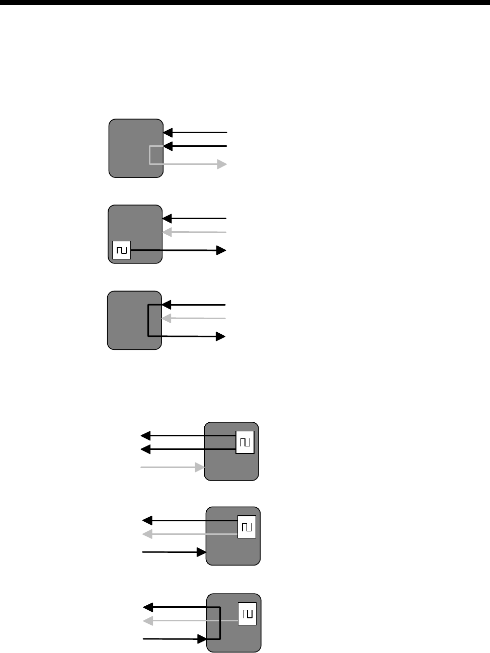
Module configuration 4-81
© 1993 - 2000 Jtec Pty Limited
V.35 DTE port clocking options
The V.35 DTE port always uses RxC to clock RxD. The clock for TxD can be any one
of the three options shown below:
RxC+TxC (DCE sourced Rx and Tx clocks)
RxC+ETxC (DCE sourced Rx clock, independent DTE sourced Tx clock)
ETxC=RxC (DCE sourced Rx clock, looped to DTE sourced Tx clock)
V.35 DCE port clocking options
There are three different options for a V.35 DCE port:
RxC+TxC (DCE sourced Rx and Tx clocks)
RxC+ETxC (DCE sourced Rx clock, DTE sourced Tx clock)
RxC=ETxC (DTE supplied Tx clock, looped to Rx clock)
RxC
TxC
ETxC
Receive (input) data clocked by RxC
Transmit (output) data clocked by TxC
RxC
TxC
ETxC
Receive (input) data clocked by RxC
Transmit (output) data clocked by ETxC
RxC
TxC
ETxC
Receive (input) data clocked by RxC
Transmit (output) data clocked by ETxC
RxC
TxC
ETxC
Receive (output) data clocked by RxC
Transmit (input) data clocked by TxC
RxC
TxC
ETxC
Receive (output) data clocked by RxC
Transmit (input) data clocked by ETxC
RxC
TxC
ETxC
Receive (output) data clocked by RxC
Transmit (input) data clocked by ETxC
4-82 Digital Trunk Module (DTM)
10003497.00 Rev.5
X.21 DTE port clocking options
There are three different X.21 DTE clocking options as shown below:
S only (DCE sourced clock for Rx and Tx)
S+X (DCE sourced Rx clock, independent DTE sourced Tx clock)
X=S (DCE sourced Rx clock, looped to DTE sourced Tx clock)
X.21 DCE port clocking options
There are three different X.21 DCE port clocking options as shown below:
S Only (DCE sourced clock for Rx and Tx)
S+X (DCE sourced Rx clock, DTE sourced Tx clock)
S=X (DTE sourced Tx clock, looped to Rx clock)
SReceive (input) data clocked by S
Transmit (output) data clocked by S
S
X
Receive (input) data clocked by S
Transmit (output) data clocked by X
S
X
Receive (input) data clocked by S
Transmit (output) data clocked by X
SReceive (output) data clocked by S
Transmit (input) data clocked by S
S
X
Receive (output) data clocked by S
Transmit (input) data clocked by X
S
X
Receive (output) data clocked by S
Transmit (input) data clocked by X

Module configuration 4-83
© 1993 - 2000 Jtec Pty Limited
Trunk quality reporting
Private carriers claim performance statistics for their private trunk links. The DTM
performs running trunk quality measurements on each trunk and provides two types
of reports:
Trunk Quality Log
This logs the following trunk quality statistics:
•Errored Seconds
•approximate BER (based on CRC errors)
•Number of Synchronisation Losses
•Number of Received Data Slips
•Number of Transmitted Data Slips.
Trunk Quality Alarm
This logs alarms when trunk quality statistics reach or exceed specified thresholds
for the following parameters:
•Errored Seconds
•CRC Errors (400 CRC checks/ second)
•Number Synchronisation Losses
•Number of Received Data Slips
•Number of Transmitted Data Slips.
Both report logging types are performed over specified intervals while selected.
Normal alarms are also generated when Trunk Quality Alarm is selected and a
transition occurs for any of the above specified parameters (see below).

4-84 Digital Trunk Module (DTM)
10003497.00 Rev.5
Alarms
The following alarm messages are generated by the DTM and will appear in the
Alarm Log when the corresponding events occur:
•Card OK
•Card Failure
•Layer 2 OK
•Layer 2 Failure
•Network Clocks Gone
•Network Clocks Present
•Bus Clocks Gone
•Bus Clocks Present
•Trunk Clocks Incorrect
•Errored Second Threshold Reached
•Errored Second Threshold Not Reached
•CRC Error Threshold Reached
•CRC Error Threshold Not Reached
•Synchronisation Threshold Reached
•Synchronisation Threshold Not Reached
•Receive Data Slips Threshold Reached
•Receive Data Slips Threshold Not Reached
•Transmit Data Slips Threshold Reached
•Transmit Data Slips Threshold Not Reached
See the OmniVision User Manual for further information.

Module configuration 4-85
© 1993 - 2000 Jtec Pty Limited
subB-channel usage
When the subB-channel is used in a TimeFrame Virtual Line, a voice compression
module (in a COMBO, MFCM or LDCM) or a Subrate Multiplexing Module (SRMM)
is required. See the relevant module section for information on the modules. The bits,
as displayed by the Network Management System, that will be available for use are:
The subB-channel can be also used on-demand with DLM data bandwidth less than
or equal to the configured subB-channel speed. The DLM used should have the Bearer
Capability selected to reflect the DLM speed (refer to any DLM configuration section
in this manual). The DLM (if able) can use the following CCITT (ITU-T) speeds: 600,
1.2 k, 2.4 k, 4.8 k, 9.6 k, 19.2 k (bit/s) and all non-CCITT (ITU-T) speeds less than or
equal to 56 kbit/s.
Configuration
Overview
One to four plug-in submodules can be plugged in each DTM, supporting any
combination of independent trunk ports. You can configure the DTM using
OmniVision. The exception is NT/TE selection, which is made by hardware links on
a per port basis.
A DTM trunk port can automatically synchronise to a remote port if the remote port
has already been correctly configured.
For further information on the configuration procedure, refer to Virtual eXchange on
page 3-14. The perspective used here is that line interface cards (for example, QDLM,
ALEM and so on) are viewed as NTs. Calls routed between line interface cards and
a DTM NT port can only be achieved through the VX.
subB From Bit To Bit
56 kbit/s 7 1
48 kbit/s 7 2
40 kbit/s 7 3
32 kbit/s 7 4
24 kbit/s 7 5
16 kbit/s 7 6
8 kbit/s 7 7

4-86 Digital Trunk Module (DTM)
10003497.00 Rev.5
Trunk numbering
NT trunk numbering
Port number range The NT’s Minimum Number and Maximum Number define the valid number range
for this NT trunk. Any calls that arrive at this device (either by TE or another NT when
running the VX) that match this number range will be routed to this trunk.
The Minimum Number and Maximum Number automatically create a lineset that
has all configured B-, subB- and D-channels as its members. This lineset can be viewed
through Edit Lineset.
More number ranges can be attributed to each trunk using the Edit Lineset command.
If Edit Lineset is used and the subB-channel is to be used in an on-demand call
situation, the Attributes for Destination Type must be set to Linear Hunting (custom
selection) and the Member Lines must start with the subB-channel. This ensures that
calls are size checked for subB-channel connection first before whole B-channels. To
reduce call collisions in an NT-NT connection, it is recommended to make one NT
reverse the Member Lines ordering.
TE trunk numbering
Numbering TE line numbering is made up of a Base Number, Group Number and area code.
The Base Number has two implications:
•Incoming Called Party Number - Base Number = line interface called
•Base Number + line interface number of caller = Calling Party Number.
The Base Number is useful when there is more than one network card access because
it allows each line to have an alias for each network access.
The Group Number is used to form the Calling Party Number for outgoing calls when
the line making the call cannot supply a Calling Party Number.
For Australia, the 'area code' (without any subscriber trunk dialling code digits) refers
to the area code without the initial zero. This area code is used in conjunction with a
line number when forming the calling party number for outgoing calls.
Trunk Port Setup
There are four configurable parameters: Interface Mode, Clock Sources, Trunk Speed
and D/subB Speed.

Module configuration 4-87
© 1993 - 2000 Jtec Pty Limited
Interface Mode Interface Mode selects the trunk port to be either a DTE (default) or DCE.
Notes
•The V.35 requires different 26-pin female high density D-type to standard 34-pin
rectangular connector adaptor cables for DTE and DCE mode (see Installation
Manual).
•This selection is made independent of NT/TE trunk type.
Clock Sources The Clock Sources selections are a function of Interface Mode and interface type, that
is, X.21 or V.35. The relationship is shown as follows:
•DCE X.21 - S only, S+X or S=X
•DTE X.21 - S only (default), S+X or X=S
•DCE V.35 - RxC+TxC, RxC+ETxC or RxC=ETxC
•DTE V.35 - RxC+TxC (default), RxC+ETxC or ETxC=RxC.
To maximise cable length between DTE and DCE, make a Clock Sources selection that
allows clocks to run in the same direction as the data for each direction. For example,
in the case of an X.21 DTE port the selection of S+X or X=S would enable clocks to
run in the same direction as the data for both R and T. The difference is that S+X uses
its own clock source (synchronised to its own reference clock) and X=S loops the
externally received S clock back (preserving the frequency) as the X clock.
Trunk Speed The available Trunk Speeds are given in two forms: bits/s and B-channels. The
selectable speeds are: 48k, 56k, and 64k up to 2.048Mbit/s in 64kbit/s steps. No full
B-channels are available for a Trunk Speed less than 128kbit/s. For a Trunk Speed of
128 kbit/s one B-channels is available, with one B-channel being added for every
additional 64 kbit/s. Note that it is also possible to turn DTM trunk ports off.
The default startup condition of unconfigured DTM ports, is automatic speed
detection. In this mode the trunk speed is sourced from the interface clock, providing
there is an idle configured DTM port at the trunk’s remote end. Once the speed is
determined, the port is automatically configured to the detected speed. This allows
remote devices, connected through the DTM, a remote OmniVision session for further
configuration.

4-88 Digital Trunk Module (DTM)
10003497.00 Rev.5
Channel speeds There is a trade-off between D-channel and subB-channel speeds. The available
D/subB Speed is therefore given in two forms: subB bit/s and D bit/s. The available
selections of speed are also a function of the Trunk Speed. D/subB speeds are in steps
of 8 kbit/s, with the available speeds as follows:
48 kbit/s Trunk 56 kbit/s Trunk ≥ 64 kbit/s Trunk
The faster the subB-channel, the slower the D-channel signalling will be. This will
become more evident as the amount of simultaneous calls increases or during remote
D-channel management sessions, where a lot of data is passed across the D-channel.
Options
NT Options
The NT-specific options consist of three parameters: Outgoing TE, Edit lines and
Channel Negotiation.
Outgoing TE You can select the TE to be used for calls going out from this NT port. The outgoing
TE can be: Any (default), Preferred or Exclusive.
When Preferred is selected, calls will be routed from this DTM port to the nominated
TE if possible, otherwise another TE will be used. When Exclusive is selected, calls
will be routed from this DTM port to the nominated TE only. If the call cannot be
routed through the nominated TE then the call will be cleared.
Note The terms outgoing and incoming are with respect to a TE port. Thus the term
outgoing applies to a call that originates from a device that is connected to an NT port.
Edit lines Edit Lines allows access to the Line Configuration dialog for each data (B/subB)
channel. This is normally not used because the NT port usually receives call
parameters from its attached TE. Refer to Line configuration on page 2-5 for further
information.
Applications Select this to connect to either a VX DTM NT port (default) or a DTM TE port.
D-
Channel subB-
Channel D-
Channel subB
-Channel D-
Channel subB-
Channel
440 448 456
12 32 12 40 12 48
20 24 20 32 20 40
28 16 28 24 28 32
36 8 36 16 36 24
44 0 44 8 44 16
52 0 52 8
60 0

Module configuration 4-89
© 1993 - 2000 Jtec Pty Limited
Channel Negotiation Enable if you want channel negotiation on incoming calls.
When this parameter is enabled, a ’preferred’ channel is selected. The network may
however want to use the designated channel to set up its own outgoing call and will
require the incoming call to be set up on a different channel. In this case the network
will attempt to negotiate the incoming call to another channel. This feature helps to
prevent calls from being rejected should a call collision occur.
When disabled, the call from the device specifies an ’exclusive’ channel, and if a
collision occurs, the incoming call is rejected.
TE Options
The TE-specific options consist of two check boxes: T309 Disable and Retain layer 2
establishment.
T309 Disable When enabled (default), the T309 is a timer that causes calls to clear 15 seconds after
a D-channel link failure is detected. If it is disabled, calls clear as soon as D-channel
link failure is detected.
Retain layer 2
establishment When enabled (default) this option tells the DTM port to maintain the D-channel
LAPD data link in the established state at all times. When disabled the data link is
maintained only while it is required for call signalling. The setting of this option
affects call processing as follows:
•When Retain layer 2 establishment is enabled: If the D-channel LAPD data link
fails, the DTM will report a Layer 2 failure alarm. The CM or RM will not submit
outgoing calls to the port until the alarm is cleared by Layer 2 being
re-established.
•When Retain layer 2 establishment is disabled: The CM or RM can submit calls
to the port regardless of the status of Layer 2. If the D-channel LAPD data link
cannot re-establish, the CM or RM will resubmit the call to another network
port. The process of detecting failure to re-establish the data link takes four
seconds if T309 is disabled or 15 seconds if T309 is enabled.
Notes
•Retain layer 2 establishment should be enabled for unused DTM ports. This ensures that
a layer 2 alarm condition exists so that the CM or RM will not route outgoing calls to
the port.
•When Retain layer 2 establishment is disabled, T309 should also be disabled so as to avoid
long delays in call resubmission.
Exclusive/Preferred
use only Enabling this removes the module from the TE table. The TE can then only be used
for outgoing calls if the NT making the call has Outgoing TE exclusive selected.
NT/TE common options
There are four options common to both NT and TE. These options are: ’Don’t use as
clock reference', 'Trunk Quality Reporting', 'Don’t use as bus master' and 'Don’t use
for D-channel calls'.

4-90 Digital Trunk Module (DTM)
10003497.00 Rev.5
Don’t use as clock
reference This option prevents a DTM port from being selected as the backplane reference clock
provider. When a port is chosen to be the reference clock provider, the reference clock
is phase locked to the trunk port’s incoming clock, according to the table below.
If the incoming trunk clock becomes unstable or non-existent while the DTM port is
providing the reference clock to the backplane, the DTM free runs.
Note Care should be taken when both ends of a DTM trunk are providing reference clock
to the backplanes. This is because both ports will be deriving their clocks from each other,
forming a feedback loop. This situation can be avoided by allowing only one end of a trunk
link the ability to provide reference clocks to the backplane.
Don’t use for
D-channel calls Enable this to prevent the Resource Manager or Control Module from delivering
outgoing D-channel calls through the DTM.
Don’t use as bus
master Enable this to prevent the DTM being selected to provide the backplane bus clock.
Trunk quality reporting
Trunk quality reporting has three main parameters:
•Report Type: Trunk Quality Log and Trunk Quality Alarm
•Reporting Period
•Alarm Thresholds.
Report Type
There are two options: Trunk Quality Log and Trunk Quality Alarm. The Reporting
Period and Alarm Thresholds areas are unavailable when both Report Types are
unselected (default).
Trunk Quality Log When Trunk Quality Log is selected, the DTM continuously reports Trunk Quality
Data over time periods as specified by the Reporting Period.
Trunk Quality Alarm When Trunk Quality Alarm is selected, the DTM continuously reports Trunk Quality
Alarms over time periods as specified by the Reporting Period. The contents of the
logged alarms reflect whether each specified Alarm Threshold has or has not been
reached. Normal alarms are also generated when Trunk Quality Alarm is selected
and a transition occurs for any of the Alarm Threshold selections (see Alarms on page
4-84).
Reporting period When either or both Report Types are selected, the Reporting Period is activated. The
selections for the Reporting Period are: 1 minute, 15 minutes, 1 hour and 12 hours.
Alarm thresholds When Trunk Quality Alarm is selected, the Alarm Thresholds section is also activated.
The data field selections for the Alarm Thresholds are: Errored Seconds, CRC Errors,
Sync Losses, Receive Slips and Transmit Slips.
Interface Type Incoming Clock
DCE X.21 X
DTE X.21 S
DCE V.35 ETxC
DTE V.35 RxC

Module configuration 4-91
© 1993 - 2000 Jtec Pty Limited
V.24 Asynchronous Digital Line Module (ADLM V.24)
The V.24 Asynchronous Digital Line Module (ADLM V.24) is a V.24 DCE as defined
in the ITU-T (CCITT) recommendations. It can connect two asynchronous V.24 DTEs
to the ISDN, or DCEs if null modem cables are used. These DTEs can be computers,
modems, or other devices which communicate using asynchronous V.24 (or RS-232)
data formats.
The ADLM V.24 simulates the operation of an AT compatible modem by providing
a subset of the AT command set which is translated to the ISDN D-channel protocol.
See Appendix C — AT Commands for more details.
The ADLM V.24 provides data rate adaption of user data to the 64 kbit/s ISDN
B-channel, or nx8 kbit/s sub-channels, using I.463 (V.110) and ECMA 102 compatible
data rate adaption.
In Australia, the data word size can be 8-bit, 7-bit with parity or 7-bit without parity.
Parity is only allowed for 7-bit data (in accordance with ECMA 102 and TPH 1856
specifications). The parity bit can be odd, even, forced to 0, or forced to 1. The number
of stop bits can be either 1 or 2.
In the UK, parity is not used.
The ADLM V.24 allows you to select normal or Hotline dialling, or semipermanent
operation for each V.24 port. You can also choose to establish and clear calls using
either the AT command set, the DTR signal alone or OmniVision.
Note Refer to Appendix C for a list of the available AT commands.
Configuration
Line Number Enter the line number for this line. See Parameters, page 2-5 for information about the
Line Number.
Subaddress Enter the Subaddress if required. It is not mandatory to enter anything in this
parameter. See Parameters, page 2-5 for more information.
Port ID Enter the Port ID if required. The default setting for this parameter is 0. See Parameters,
page 2-5 for more information. It is not mandatory to enter anything in this parameter.
Port Name Enter the Port Name if required. It is not mandatory to enter anything in this
parameter. See Parameters, page 2-5 for more information.
RM CM
4-92 V.24 Asynchronous Digital Line Module (ADLM V.24)
10003497.00 Rev.5
ISDN Interface — Bearer Capability
The settings for these parameters determine the bearer transfer characteristics of the
ISDN for outgoing calls. The following table shows the default settings. Accept the
defaults for all the parameters.
ISDN Interface — Low Layer Compatibility
The settings for these parameters are determined by the capability of the equipment
used. The defaults for both incoming calls and outgoing calls are ’disabled’. For
further information about the default settings, refer to Parameters, page 2-7.
ISDN Interface — High Layer Compatibility defaults
Parameter Default
Octet 3 Standard CCITT (ITU-T)
Transfer Unrest.Digital
Parameter Default
Call Direction Incoming None
Outgoing None

Module configuration 4-93
© 1993 - 2000 Jtec Pty Limited
ISDN Interface — Call Establishment Modes defaults
Changing Call Establishment Modes defaults
Semipermanent
(where available) Select Enable and enter the semipermanent label to set up a semipermanent call from
the V.24 line.
Select Backup to replace the SPC with a switched call if the V.110 three second
disconnection rule is broken. When the Backup call is initiated, an alarm is invoked
(if enabled).
Parameter Default
Semipermanent
(where available) Enable Disabled
Backup Disabled
Label —
Member of Subrate Virtual
Line or manually connected
(UK only)
Yes Disabled
Hotline Enable —
Number —
XSPC Disabled
Subaddress —
Active Call Facilities Don't release call if V110
frame loss detected Disabled
Call Control DTR blocking Disabled
Auto Answer Disabled
Release on progress Enabled
AT Disabled
DTR call Enabled
GSM Pass CLI in Disabled
Pass CLI out Disabled
Pass B number in Disabled
Pass Causes Disabled
Control Leads Local Only Enabled
Transferred Inband Disabled
GSM mode Disabled
DTR Alarm Timeout —5 secs

4-94 V.24 Asynchronous Digital Line Module (ADLM V.24)
10003497.00 Rev.5
To set up the semipermanent backup operation
1 Enter an SPC label at both ends of the link and select Enable.
2 Select Backup at both ends of the link.
3 Set up a Hotline call to the line number at the other end of the link.
4 Select Auto Answer at the other end of the link.
Member of Subrate
Virtual Line or
manually connected
(UK only)
Select Yes if the line is a part of a Subrate Virtual Line or manually connected. It
enables data to be transferred directly onto the B-channel without the call being set
up. If you do not select this, the port does not transmit or receive data until a call is
received or initiated by the port.
Hotline To set up a Hotline call, enter the called party number and select Enable. Enter the
subaddress, if required.
Select XSPC to enable a Switched semipermanent connection. This is only available
with a Hotline call.
Active Call Facilities Select Don’t release call if V110 frame loss detected to ignore the V.110 three second
disconnection rule.
Call Control If you clear all of the Call Control checkboxes, the ADLM only answers calls to this
line when the DTR signal is on.
Select AT to use the AT protocol for call control between the DTE and the ADLM.
Select DTR Call to initiate and clear calls with the DTR lead.
Select DTR Blocking to accept incoming calls when DTR lead is high and to fail calls
when DTR lead is low.
Set Release on progress to release a call even if a Progress Indicator is sent.
Note You cannot select both AT and DTR Call at the same time.
Control Leads Select Local Only to turn all leads on after calls are started.
Select Transferred Inband to transmit the state of the control leads to the other end.
If you have not selected this, an ON state will be transmitted for each lead irrespective
of the actual states presented to the port.
GSM mode Select if you want end-to-end control mapping for GSM applications.
GSM Set Pass CLI In to allow the CLI (Calling Line Identifier/ Calling Party Number) from
the ADLM port to pass to the user TE to which it is physically connected. If disabled,
the CLI numbers will not be passed. This setting only affects incoming ISDN calls to
the ADLM port and not the outgoing ones.
Set Pass CLI Out to allow for the CLI numbers from the user TE originating the call
to pass to the ADLM port to which it is physically connected. If disabled, an error
indication is returned by the ADLM port to the user TE to which it is physically
connected, and the initiated call by the user TE is rejected. This setting only applies
to outgoing ISDN calls from the ADLM and not the incoming ones.
Note When set, Pass CLI Out causes the port to be seized as soon as the ’ATD’ command
is received. This reduces the chance of call collisions

Module configuration 4-95
© 1993 - 2000 Jtec Pty Limited
Set Pass B number in to allow the Called Party Number from the ADLM port to be
passed to the user TE. If disabled, B numbers are not passed. This setting only affects
incoming ISDN calls to the ADLM.
Set Pass causes to allow the CAUSES of the termination of ISDN calls from the ADLM
port to pass to the USER TE. If disabled, causes are not passed. This setting is effective
only if ADLM port is not the initiator of the termination of the ISDN call.
DTR alarm timeout This parameter is effective only when DTR blocking mode is enabled. Four settings
are available: 0, 5, 10 and 30 seconds. If DTR goes to a low state for more than the time
specified, an alarm is generated by the RM or CM.
ISDN Interface — ISDN Line Controls
The following table shows the ISDN Line Controls defaults.
ISDN Line Controls
Changing ISDN Line Controls defaults
AOC
(where available) Select either Continuous or End to log the cost of each call from this line. You can
view the cost details via Call Log within the NMS. For further details, refer to the
OmniVision User Manual.
This is only available if you subscribe to an AOC service.
Calling Line ID Do not select CLIP (CLI Presentation).
If you select CLIR (CLI Restriction), calls from this line do the opposite of the site
default. For example, if your site default presents CLI for outgoing calls and you select
CLIR, calls from this line do not present CLI to the called party.
CLIVE List
Assignment Select this option to apply a CLI/Number Checking list to this line. See page 3-49 of
the System Configuration section for more information.
Numbering format Select the appropriate CCITT (ITU-T) standard for Line Number, Hotline Number,
and Line and Hotline Subaddress formats.
ISDN Interface defaults
Teleservice
(where available) None.
Parameter Default
AOC
(where available) None Selected
Continuous or End of Call Cleared
Calling Line ID CLIP Cleared
CLIR Cleared
Numbering format Line No E.164
Hotline E.164
Line and Hotline Subaddress NSAP
CLIVE List
Assignment This line checks —
Available CLI/Number lists —

4-96 V.24 Asynchronous Digital Line Module (ADLM V.24)
10003497.00 Rev.5
Changing ISDN Interface defaults
Teleservice
(where available) Select Timelink if you have subscribed to this service.
ISDN Internal Control defaults
Restriction None.
Outgoing TE Any.
Changing ISDN Internal Control defaults
Restriction Select Disable from the list to prevent calls being made to or from this line.
Select In Only or Out Only to allow calls in the selected direction only.
Outgoing TE Select the required TE. If you select Preferred or Exclusive, you must then select the
TE from the displayed list. This setting affects all the module’s lines.

Module configuration 4-97
© 1993 - 2000 Jtec Pty Limited
V.24 Synchronous Digital Line Module (SDLM V.24)
The V.24 Synchronous Digital Line Module (SDLM V.24) is a V.24 DCE as defined in
the ITU-T (CCITT) recommendations. It provides interfaces for two synchronous V.24
DTEs to the ISDN. The DTEs can be computers, terminals, or other devices which
communicate using synchronous V.24 (or RS-232) data formats.
The SDLM V.24 provides data rate adaption of user data to the 64 kbit/s ISDN
B-channel, or nx8 kbit/s subchannel, using ITU-T (CCITT) X.30 and I.463 (V.110) and
ECMA 102 compatible data rate adaption.
Different signalling modes can be configured for an SDLM V.24 interface, and each
interface on a module can be configured differently. In each case, translation to the
appropriate ISDN signalling is performed by the device.
Hotline dialling
When Hotline dialling is used, the SDLM V.24 is perceived by the DTE as a leased
line modem. The number to be called by a particular SDLM V.24 interface is
configured before any calls are made. The DTE can make a call by raising the DTR
signal. The device sends a call setup message on the ISDN link to the exchange with
the complete called party number. The call is connected to the remote party and when
end-to-end communication is established the DCD signal is raised by the SDLM. You
can also initiate and clear calls through OmniVision.
When DTR Call is enabled as the call control method the DTE can disconnect a Hotline
call by dropping the DTR signal.
Semipermanent operation (where available)
Semipermanent operation is fully supported in Australia. In semipermanent
operation, the SDLM is perceived by the DTE as a leased line modem.
Configuration
Line Number Enter the line number for this line. See Parameters, page 2-5 for further information.
Subaddress Enter the Subaddress if required. It is not mandatory to enter anything in this
parameter. See Parameters, page 2-5 for more information.
Port ID Enter the Port ID if required. The default setting for this parameter is 0. See Parameters,
page 2-5 for more information. It is not mandatory to enter anything in this parameter.
Port Name Enter the Port Name if required. It is not mandatory to enter anything in this
parameter. See Parameters, page 2-5 for more information.
RM CM

4-98 V.24 Synchronous Digital Line Module (SDLM V.24)
10003497.00 Rev.5
ISDN Interface — Bearer Capability defaults
The settings for these parameters determine the bearer transfer characteristics of the
ISDN for outgoing calls. The following table shows the default settings. Accept the
defaults for all the parameters.
ISDN Interface — Low Layer Compatibility
The settings for these parameters are determined by the capability of the equipment
used. The defaults for both incoming calls and outgoing calls are ’disabled’. For
further information about the default settings, refer to Parameters, page 2-7.
ISDN Interface — High Layer Compatibility defaults
ISDN Interface — Call Establishment Modes defaults
Parameter Default
Octet 3 Standard CCITT (ITU-T)
Transfer Unrest.Digital
Parameter Default
Call Direction Incoming None
Outgoing None
Parameter Default
Semipermanent
(where available) Enable Disabled
Backup Disabled
Label —
Member of Subrate
Virtual Line or manually
connected (UK)
Yes Disabled
Hotline Enable —
Number —
XSPC Disabled
Subaddress —
Active Call Facilities Don't release call if V110
frame loss detected Disabled
Call Control Auto Answer Disabled
DTR Call Enabled
Control Leads Local Only Enabled
Transferred Inband Disabled

Module configuration 4-99
© 1993 - 2000 Jtec Pty Limited
Changing Call Establishment Modes defaults
Semipermanent
(where available) Select Enable and enter the semipermanent label at both ends to set up a
semipermanent call from the V.24 line.
You can select Backup to replace the semipermanent connection with a switched call
if the V.110 three second disconnection rule is broken. When the Backup call is
initiated, an alarm is invoked.
To set up the semipermanent backup operation
1 Enter an SPC label at both ends of the link and select Enable.
2 Select Backup at both ends of the link.
3 Set up a Hotline call to the line number at the other end of the link.
4 Select Auto Answer at the other end of the link.
Member of Subrate
Virtual Line or
manually connected
Select Yes if the line is a part of a Subrate Virtual Line or manually connected.
It enables data to be transferred directly onto the B-channel without the call being set
up.
If you do not select this, the port does not transmit or receive data until a call is
received or initiated by the port.
Hotline To set up a Hotline call, enter the called party number and select Enable. Enter the
subaddress, if required.
Select XSPC to enable a Switched Semi-Permanent Connection.
Active Call Facilities Select Don’t release call if V110 frame loss detected if you want to ignore the V.110
three second disconnection rule.
Call Control Select DTR Call to use the DTR signal to initiate and clear calls on this line.
Select Auto Answer if you want incoming calls to be connected automatically.
If you clear all of the Call Control checkboxes, the SDLM only answers calls to this
line when the DTR signal is on.
Control Leads Select Local Only to turn all leads on after calls are started.
Select Transferred Inband to transmit the state of the control leads to the other end.
This only occurs if a V.110 rate (LLC) is selected. If this is not selected, an ON state
will be transmitted for each lead irrespective of the actual states presented to the port.

4-100 V.24 Synchronous Digital Line Module (SDLM V.24)
10003497.00 Rev.5
ISDN Interface — ISDN Line Controls
The following table shows the ISDN Line Controls defaults.
ISDN Line Controls
Changing ISDN Line Controls defaults
AOC
(where available) Select either Continuous or End to log the cost of each call from this line. You can
view the cost details via OmniVision’s Call Log. For further details, refer to the
OmniVision User Manual. This is only available if you subscribe to an AOC service.
Calling Line ID Do not select CLIP (CLI Presentation).
If you select CLIR (CLI Restriction), calls from this line do the opposite of the site
default. For example, if your site default presents CLI for outgoing calls and you select
CLIR, calls from this line do not present CLI to the called party.
CLIVE List
Assignment Select this option to apply a CLI/Number Checking list to this line. See page 3-49 of
the System Configuration section for more information.
Numbering format Select the appropriate CCITT (ITU-T) standard for Line Number, Hotline Number,
and Line and Hotline Subaddress formats.
ISDN Interface defaults
Teleservice
(where available) None.
Changing ISDN Interface defaults
Teleservice
(where available) Select Timelink if you subscribe to this service.
ISDN Internal Control defaults
Restriction None.
Outgoing TE Any.
Parameter Default
AOC
(where available) None Selected
Continuous or End of Call Cleared
Calling Line ID CLIP Cleared
CLIR Cleared
Numbering format Line No E.164
Hotline E.164
Line and Hotline Subaddress NSAP
CLIVE List
Assignment This line checks —
Available CLI/Number lists —

Module configuration 4-101
© 1993 - 2000 Jtec Pty Limited
Changing ISDN Internal Control defaults
Restriction Select Disable from the list to prevent calls being made to or from this line.
Select In Only or Out Only to allow calls in the selected direction only.
Outgoing TE Select the required TE. If you select Preferred or Exclusive, you must then select the
TE from the displayed list. This setting affects all the module’s lines.

4-102 X.21 Synchronous Digital Line Module (SDLM X.21)
10003497.00 Rev.5
X.21 Synchronous Digital Line Module (SDLM X.21)
The X.21 Synchronous Digital Line Module (SDLM X.21) is an X.21 DCE as defined
in the recommendations of ITU-T (CCITT). It can connect two X.21 DTEs to the ISDN,
providing:
•conversion of the X.21 protocol to the ISDN protocol
•bit rate adaption from the user rate to the B-channel rate at 64 kbit/s or nx8 kbit/s.
The SDLM X.21 allows you to select normal or Hotline dialling, or semipermanent
operation for each X.21 port. You can also choose to establish and clear calls using
either full X.21 protocols, the C signal alone or OmniVision.
For further discussion on X.21 interfaces, refer to Appendix G.
Configuration
Line Number Enter the line number for this line. See Parameters, page 2-5 for further information.
Subaddress Enter the Subaddress if required. It is not mandatory to enter anything in this
parameter. See Parameters, page 2-5 for more information.
Port ID Enter the Port ID if required. The default setting for this parameter is 0. See Parameters,
page 2-5 for more information. It is not mandatory to enter anything in this parameter.
Port Name Enter the Port Name if required. It is not mandatory to enter anything in this
parameter. See Parameters, page 2-5 for more information.
ISDN Interface — Bearer Capability
The settings for these parameters determine the bearer transfer characteristics of the
ISDN for outgoing calls. The following table shows the default settings. Accept the
defaults for all the parameters.
ISDN Interface — Low Layer Compatibility
The settings for these parameters are determined by the capability of the equipment
used. The defaults for both incoming calls and outgoing calls are ’disabled’. For
further information about the default settings, refer to Parameters, page 2-7.
Parameter Default
Octet 3 Standard CCITT (ITU-T)
Transfer Unrest.Digital
RM CM

Module configuration 4-103
© 1993 - 2000 Jtec Pty Limited
ISDN Interface — High Layer Compatibility defaults
ISDN Interface — Call Establishment Modes defaults
Changing Call Establishment Modes defaults
Semipermanent Select Enable and enter the semipermanent label to set up a semipermanent call from
the X.21 line.
Select Backup to replace the SPC with a switched call if the V.110 three second
disconnection rule is broken. When the Backup call is initiated, an alarm is invoked
(if enabled).
To set up the semipermanent backup operation
1 Enter an SPC label at both ends of the link and select Enable.
2 Select Backup at both ends of the link.
3 Set up a Hotline call to the line number at the other end of the link.
4 Select Auto Answer at the other end of the link.
Parameter Default
Call Direction Incoming None
Outgoing None
Parameter Default
Semipermanent
(where available) Enable Disabled
Backup Disabled
Label —
Member of Subrate
Virtual Line or manually
connected (UK only)
Yes Disabled
Hotline Enable —
Number —
XSPC Disabled
Subaddress —
Active Call Facilities Don't release call if V.110
frame loss detected Disabled
Call Control Auto Answer Disabled
X.21 Call Disabled
C Signal Enabled
Control Leads Local Only Enabled
Transferred Inband Disabled

4-104 X.21 Synchronous Digital Line Module (SDLM X.21)
10003497.00 Rev.5
Member of Subrate
Virtual Line or
manually connect
(UK only)
Select Yes if the line is a part of a Subrate Virtual Line or manually connected.
It enables data to be transferred directly onto the B-channel without the call being set
up.
If you do not select this, the port does not transmit or receive data until a call is
received or initiated by the port.
Hotline To set up a Hotline call, enter the called party number and select Enable. Enter the
subaddress, if required.
Select XSPC to enable a switched semipermanent connection.
Active Call Facilities Select Don’t release call if V.110 frame loss detected if you want to ignore the V.110
three second disconnection rule.
Call Control Select X.21 to use the X.21 protocol for call control between the DTE and the SDLM.
Select C Signal to use the C Signal line to initiate and clear calls on this line.
Select Auto Answer to connect incoming calls automatically.
If you clear all of the Call Control checkboxes, the SDLM only answers calls to this
line when the C signal is on.
Note You cannot select X.21 and either C Signal or Auto Answer at the same time.
Control Leads Select Local Only to turn all leads on after calls are started.
Select Transferred Inband to transmit the state of the control leads to the other end.
If this is not selected, an ON state will be transmitted for each lead irrespective of the
actual states presented to the port. Control lead states can only be transferred at data
rates less than or equal to 19.2 kbit/s.
ISDN Interface — ISDN Line Controls
The following table shows the ISDN Line Controls defaults.
ISDN Line Control defaults
Parameter Default
AOC
(where available) None Selected
Continuous or End of Call Cleared
Calling Line ID CLIP Cleared
CLIR Cleared
Numbering format Line No E.164
Hotline E.164
Line and Hotline Subaddress NSAP
CLIVE List
Assignment This line checks —
Available CLI/Number lists —

Module configuration 4-105
© 1993 - 2000 Jtec Pty Limited
Changing ISDN Line Controls defaults
AOC
(where available) Select either Continuous or End to log the cost of each call from this line. You can
view the cost details via OmniVision’s Call Log. For further details, refer to the
OmniVision User Manual.
This is only available if you subscribe to an AOC service.
Calling Line ID Do not select CLIP (CLI Presentation).
If you select CLIR (CLI Restriction), calls from this line do the opposite of the site
default. For example, if your site default presents CLI for outgoing calls and you select
CLIR, calls from this line do not present CLI to the called party.
CLIVE List
Assignment Select this option to apply a CLI/Number Checking list to this line. See page 3-49 of
the System Configuration section for more information.
Numbering format Select the appropriate CCITT (ITU-T) standard for Line Number, Hotline Number,
and Line and Hotline Subaddress formats.
ISDN Interface defaults
Teleservice
(where available) None.
Changing ISDN Interface defaults
Teleservice
(where available) Select Timelink if you have subscribed to this service.
ISDN Internal Control defaults
Restriction None.
Outgoing TE Any.
Changing ISDN Internal Control defaults
Restriction Select Disable from the list to prevent calls being made to or from this line.
Select In Only or Out Only to allow calls in the selected direction only.
Outgoing TE Select the required TE. If you select Preferred or Exclusive, you must then select the
TE from the displayed list. This setting affects all the module's lines.

4-106 V.35 Synchronous Digital Line Module (SDLM V.35)
10003497.00 Rev.5
V.35 Synchronous Digital Line Module (SDLM V.35)
The V.35 Synchronous Digital Line Module (SDLM V.35) provides two DCE ports for
connecting DTE to the ISDN. Equipment connecting to these ports must comply with
ITU-T (CCITT) V.35 recommendations and be configured to synchronise with the
clocking signal supplied by the module.
Each port allows a DTE to communicate at data rates from 600 bit/s to 64 kbit/s for
connection onto a digital network. The SDLM V.35 provides data rate adaption of
user data to the 64 kbit/s ISDN B-channel, or nx8 kbit/s sub-channels, using I.463
(V.110) and ECMA 102 compatible data rate adaption.
Configuration
Line Number Enter the line number for this line. See Parameters, page 2-5 for more information.
Subaddress Enter the Subaddress if required. It is not mandatory to enter anything in this
parameter. See Parameters, page 2-5 for more information.
Port ID Enter the Port ID if required. The default setting for this parameter is 0. See Parameters,
page 2-5 for more information. It is not mandatory to enter anything in this parameter.
Port Name Enter the Port Name if required. It is not mandatory to enter anything in this
parameter. See Parameters, page 2-5 for more information.
ISDN Interface — Bearer Capability
The settings for these parameters determine the bearer transfer characteristics of the
ISDN for outgoing calls. The following table shows the default settings. Accept the
defaults for all the parameters.
ISDN Interface — Low Layer Compatibility
The settings for these parameters are determined by the capability of the equipment
used. The defaults for both incoming calls and outgoing calls are ’disabled’. For
further information about the default settings, refer to Parameters, page 2-7.
ISDN Interface — High Layer Compatibility defaults
Parameter Default
Octet 3 Standard CCITT (ITU-T)
Transfer Unrest.Digital
Parameter Default
Call Direction Incoming None
Outgoing None
RM CM

Module configuration 4-107
© 1993 - 2000 Jtec Pty Limited
ISDN Interface — Call Establishment Modes defaults
Changing Call Establishment Modes defaults
Semipermanent
(where available) Select Enable and enter the semipermanent label to set up a semipermanent call from
the V.35 line.
Select Backup to replace the semipermanent connection with a switched call if the
V.110 three second disconnection rule is broken. When the Backup call is initiated, an
alarm is invoked.
To set up the semipermanent backup operation
1 Enter an SPC label at both ends of the link and select Enable.
2 Select Backup at both ends of the link.
3 Set up a Hotline call to the line number at the other end of the link.
4 Select Auto Answer at the other end of the link.
Member of Subrate
Virtual Line or
manually connect
Select Yes if the line is a part of a Subrate Virtual Line or manually connected.
It enables data to be transferred directly onto the B-channel without the call being set
up.
If you do not select this, the port does not transmit or receive data until a call is
received or initiated by the port.
Hotline To set up a Hotline call, enter the called party number and select Enable. Enter the
subaddress, if required.
Select XSPC to enable a switched semipermanent connection.
Active Call Facilities Select Don’t release call if V110 frame loss detected if you want to ignore the V.110
three second disconnection rule.
Parameter Default
Semipermanent
(where available) Enable Disabled
Backup Disabled
Label —
Member of Subrate
Virtual Line or manually
connected (UK only)
Yes Disabled
Hotline Enable —
Number —
XSPC Disabled
Subaddress —
Active Call Facilities Don't release call if V.110
frame loss detected Disabled
Call Control Auto Answer Disabled
RS Call Enabled
Control Leads Local Only Enabled
Transferred Inband Disabled

4-108 V.35 Synchronous Digital Line Module (SDLM V.35)
10003497.00 Rev.5
Call Control Clear the RS Call checkbox if you do not want to use the RS signal to make and clear
calls on this line.
Select Auto Answer to connect incoming calls automatically.
If you clear all of the Call Control checkboxes, the SDLM only answers calls to this
line when the RS signal is on.
Control Leads Clear Local Only if you do not want to turn all leads on after calls are started.
Select Transferred Inband to transmit the state of the control leads to the other end.
This only occurs if a V.110 rate (LLC) is selected. If this is not selected, an ON state
will be transmitted for each lead irrespective of the actual states presented to the port.
ISDN Interface — ISDN Line Controls
The following table shows the ISDN Line Controls defaults.
ISDN Line Controls
Changing ISDN Line Controls defaults
AOC Select either Continuous or End to log the cost of each call from this line. You can
view the cost details via OmniVision’s Call Log. For further details, refer to the
OmniVision User Manual.
This is only available if you subscribe to an AOC service.
Calling Line ID Do not select CLIP (CLI Presentation).
If you select CLIR (CLI Restriction), calls from this line do the opposite of the site
default. For example, if your site default presents CLI for outgoing calls and you select
CLIR, calls from this line do not present CLI to the called party.
CLIVE List
Assignment Select this option to apply a CLI/Number Checking list to this line. See page 3-49 of
the System Configuration section for more information.
Numbering format Select the appropriate CCITT (ITU-T) standard for Line Number, Hotline Number,
and Line and Hotline Subaddress formats.
ISDN Interface defaults
Teleservice
(where available) None.
Parameter Default
AOC
(where available) None Selected
Continuous or End of Call Cleared
Calling Line ID CLIP Cleared
CLIR Cleared
Numbering format Line No E.164
Hotline E.164
Line and Hotline Subaddress NSAP
CLIVE List
Assignment This line checks —
Available CLI/Number lists —

Module configuration 4-109
© 1993 - 2000 Jtec Pty Limited
Changing ISDN Interface defaults
Teleservice
(where available) Select Timelink if you have subscribed to this service.
ISDN Internal Control defaults
Restriction None.
Outgoing TE Any.
Changing ISDN Internal Control defaults
Restriction Select Disable to prevent calls being made to or from this line.
Select In Only or Out Only to allow calls in the selected direction only.
Outgoing TE Select the required TE. If you select Preferred or Exclusive, you must then select the
TE from the displayed list. This setting affects all the module’s lines.

4-110 Quad Digital Line Module (QDLM)
10003497.00 Rev.5
Quad Digital Line Module (QDLM)
The Quad Digital Line Module (QDLM) combines most of the functions of the ADLM
and SDLMs on the same module. It has four ports each of which provides either an
X.21, V.24 or V35 interface. They can all operate as synchronous DCE ports at data
rates from 600 bit/s to 64 kbit/s. The V.24 interface can operate asynchronously from
300 bit/s to 38.4 kbit/s with programmable data format.
The QDLM adapts the user data to a 64 kbit/s B-channel in accordance with ITU-T
(CCITT) recommendations V.100 and X.30. This allows the user data to be carried on
digital leased lines or switched digital connections.
The QLDM adds features for data devices such as:
•DTE operating mode; that is, 'tail circuit' modems and NTUs can be connected
•Automatic back-up of Leased Lines
•Transfer of interface control leads at speeds up to 56 kbits/s
•Bit Error Rate Testing (BERT).
Configuration
Line Number Enter the line number for this line. See Parameters, page 2-5 for more information.
Subaddress Enter the Subaddress if required. It is not mandatory to enter anything in this
parameter. See Parameters, page 2-5 for more information.
Port ID Enter the Port ID if required. The default setting for this parameter is 0. See Parameters,
page 2-5 for more information. It is not mandatory to enter anything in this parameter.
Port Name Enter the Port Name if required. It is not mandatory to enter anything in this
parameter. See Parameters, page 2-5 for more information.
ISDN Interface — Bearer Capability
The settings for these parameters determine the bearer transfer characteristics of the
ISDN for outgoing calls. This information element is used by the ISDN to determine
whether or not interworking equipment is necessary. It does not affect the
characteristics of the QDLM interfaces. Usually, only octets 3 and 4 are required. The
following table shows the default settings. If the other octets are required they should
be set to the same values as the Low Layer Compatibility information element. The
default values are suitable for almost every application.
Parameter Default
Octet 3 Standard CCITT (ITU-T)
Transfer Unrest.Digital
Octet 4 Mode Circuit
Rate 64 kbit/s
RM CM
Module configuration 4-111
© 1993 - 2000 Jtec Pty Limited
ISDN Interface — Low Layer Compatibility
The Low Layer Compatibility information element is transmitted by the device when
setting up an outgoing call, and optionally is used to check incoming calls. It is used
to configure the data rate and asynchronous data format. The default values are
shown below for Low Layer Compatibility at speeds less than 64 kbit/s where
V.110/X.30 rate adaption is required.
The settings for these parameters are determined by the capability of the equipment
used. The defaults for both incoming calls and outgoing calls are ’disabled’. For
further information about the default settings, refer to Parameters page 2-7.
User Rate Select the required rate. The rates available are:
•300 (asynchronous only)
•600, 1200, 2400, 4800, 9600, 19200, 38400 (synchronous and asynchronous)
•48000, 56000, 64000 (synchronous only).
ISDN Interface — High Layer Compatibility defaults
ISDN Interface — Call Establishment Modes
This information is used to control how the QDLM establishes outgoing calls and
how it accepts incoming calls. See the previous sections on the ADLM V.24, SDLM
V.24, SDLM X.21 and SDLM V.35 for detailed information on Call Establishment
Modes for each type of DTE.
Before an outgoing call can be made using Hotline mode, the Hotline number and
the Hotline subaddress must be entered if required. Hotline mode must then be
enabled.
For lead call control, the DTR Call option must be enabled for V.24 and V.35 interfaces.
The C Call option must be enabled for X.21 interfaces. All other options must be
disabled with the exception of Auto Answer which may be either enabled or disabled.
Parameter Default
Octet 3 Standard CCITT (ITU-T)
Transfer Unrest. Digital
Octet 4 Mode Circuit
Outgoing None
Octet 5 Layer 1 CCITT (ITU-T) rate adaption
Parameter Default
Call Direction Incoming None
Outgoing None

4-112 Quad Digital Line Module (QDLM)
10003497.00 Rev.5
A DTE with synchronous X.21 interface can set up, answer or clear a switched call by
exchanging signals with the QDLM port. When using this X.21 call control, the X.21
option must be enabled and all other Call Control options must be disabled. This
allows the attached DTE to communicate with the QDLM according to the X.21 call
establishment protocol recommended by the ITU-T (CCITT).
Changing Call Establishment Modes defaults
See the previous sections on the ADLM V.24, SDLM V.24, SDLM X.21 and SDLM V.35
for detailed information on changing call establishment modes for each type of
interface.
Semipermanent
(where available) Enter the semipermanent number in the Label parameter and select Enable.
Hotline Enter the Hotline number and the subaddress number, if required, and select Enable.
Select XSPC to enable a Switched Semipermanent Connection.
Parameter Default
Semipermanent
(where available) Enable Disabled
Backup Disabled
Label —
Member of Subrate
Virtual Line or manually
connected
Yes Disabled
Hotline Enable Disabled
Number —
XSPC Disabled
Subaddress —
Active Call Facilities Don't release call if V.110
frame loss detected Disabled
Call Control C Blocking Disabled
Auto Answer Disabled
DTR or C Call Enabled
V.25 bis Disabled
X.21 Disabled
AT Disabled
Control Leads Local Only Enabled
Transferred Inband Disabled
GSM Mode Disabled

Module configuration 4-113
© 1993 - 2000 Jtec Pty Limited
Call Control Select V.25 bis to use Cisco V.25 bis (software release version 10) protocol for call
control between the DTE and the QDLM. All other Call Control options must be
disabled. This is available over X.21, V.35 and V.24 synchronous line interfaces.
Selecting V.25 bis allows DTEs to make outgoing calls through the QDLM.
Select C Blocking to accept incoming calls when C lead is high and to fail calls when
C lead is low.
GSM Mode Enable GSM mode to provide mapping of end-to-end control leads to interwork with
a GSM data service.
ISDN Interface — ISDN Line Controls
The following table shows the ISDN Line Controls defaults.
ISDN Line Controls
Changing ISDN Line Controls defaults
AOC
(where available) Select either Continuous or End to log the cost of each call from this line. You can
view the cost details via OmniVision’s Call Log. For further details, refer to the
OmniVision User Manual.
This is only available if you subscribe to an AOC service.
Calling Line ID Do not select CLIP (CLI Presentation).
If you select CLIR (CLI Restriction), calls from this line do the opposite of the site
default. For example, if your site default presents CLI for outgoing calls and you select
CLIR, calls from this line do not present CLI to the called party.
CLIVE List
Assignment Select this option to apply a CLI/Number Checking list to this line. See page 3-49 of
the System Configuration section for more information.
Numbering
format Select the appropriate CCITT (ITU-T) standard for Line Number, Hotline Number,
and Line and Hotline Subaddress formats.
ISDN Interface defaults
Teleservice
(where available) None.
Parameter Default
AOC
(where available) None Selected
Continuous or End of Call Cleared
Calling Line ID CLIP Cleared
CLIR Cleared
Numbering format Line No E.164
Hotline E.164
Line and Hotline Subaddress NSAP
CLIVE List
Assignment This line checks —
Available CLI/Number lists —

4-114 Quad Digital Line Module (QDLM)
10003497.00 Rev.5
Changing ISDN Interface defaults
Teleservice
(where available) Select Timelink if you have subscribed to this service.
ISDN Internal Control defaults
Changing ISDN Internal Control defaults
Restriction Select Disable to prevent calls being made to or from this line. Select In Only or Out
Only to allow calls in the selected direction only.
Operation Select DCE or DTE. Separate adaptor cables are available for DCE and DTE operation
for V.24 and V.35 interfaces.
Synch Mode This mode is only available on QDLM with V.24 interface. It allows you to set the
interface to operate in either synchronous or asynchronous mode. Note that to select
AT Call Control, Synch Mode must be selected as Asynch.
Tx Clock Select either DCE Tx Clock or DTE Tx Clock for the V.24 and V.35 interfaces. The
receive clock is always sourced by the DCE. These clock source rules are true when
the interface is configured for either DTE or DCE operation.
Outgoing TE Select the required TE. Any of the IPMT or BRMT modules in the chassis may be
selected.
V.24 V.35 X.21
Restriction None None None
Operation DCE DCE DCE
Synch mode Synch ——
Tx Clock DCE DCE —
Outgoing TE Any Any Any

Module configuration 4-115
© 1993–2000 Jtec Pty Limited
4Module configur ation
QDLM Bit Error Rate Testing (BERT)
Bit Error Rate Testing (BERT) is a QDLM diagnostic facility which enables you to
check the integrity of a data circuit. It uses the 511 bit pattern specified in ITU-T
(CCITT) O.153 to test either a switched or permanent ISDN B-channel connection for
errors. (The 511 bit pattern is used by most stand-alone Bit Error Rate Testers, such
as the HP4952.)
The QDLM BERT facility can be used between two QDLMs of any interface type and
between a QDLM and an SDLM (relevant to some testing applications).
It assumes that:
•the appropriate loopbacks (internal and external to a DLM) are configured
•any required external equipment is installed and
•a call is in place between the QDLM, using BERT and another DLM.
Before running a Bit Error Rate Test, you must establish a connection across the
network. You can do this either:
•manually, from OmniVision, before entering Diagnostic Mode or
•automatically, by selecting Start BERT. This is only possible if the QDLM is in
Hotline mode and a call is not in progress.
To clear the connection, select Stop BERT.
Configuration
There are no specific BERT parameters to configure.
Refer to the Installation Manual for an explanation of how BERT works.
Warning BERT can only operate from one port at a time.
The maximum data rate that QDLM BERT supports is 4800 bit/s.

4-116 High Speed Data Module (HSDM)
10003497.00 Rev.5
High Speed Data Module (HSDM)
The HSDM Module provides a means of connecting to high speed data networks.
The data interfaces on the HSDM typically provide high data rate links to routers and
Frame Relay networks.
The HSDM can be used across Subrate and TimeFrame Virtual Lines between nodes
in a network.
Configuration
Configuring an HSDM port applies the defaults or chosen settings to all physical and
Virtual Lines associated with the port. Individual lines within a port can be configured
separately.
Port Number Enter the port number for this port. See Parameters, page 2-5 for more information.
Subaddress Enter the Subaddress if required. It is not mandatory to enter anything in this
parameter. See Parameters, page 2-5 for more information.
Port ID Enter the Port ID if required. The default setting for this parameter is 0. See Parameters,
page 2-5 for more information. It is not mandatory to enter anything in this parameter.
Port Name Enter the Port Name if required. It is not mandatory to enter anything in this
parameter. See Parameters, page 2-5 and TimeFrame on page 3-56 for more information.
Port Setup
Interface Mode Configures the HSDM port to act as DTE or DCE. The default is DCE.
Note In DTE mode, the HSDM can provide the Reference Master Clock, which is controlled
bt the Don’t use a s Clock Reference checkbox.
Rate Adaption Allows the Rate Adaption method to be selected. See page 2-8 for further information.
The type of rate adaption selected will affect the data rates that are available on the
port.
Max Port Speed This allows the selection of the following speeds:
•600, 1200, 2400, 4800, 9600, 19200, 38400 48000, 56000, 64000 (synchronous only)
•n x 8 kbit/s up to 256 kbit/s
•n x 64 kbit/s from 256 kbit/s up to 2048 kbit/s.
Note The combined port speed of the two data ports cannot exceed 2048 kbit/s.
RM CM

Module configuration 4-117
© 1993–2000 Jtec Pty Limited
Call Establishment Modes
Click on this to open the Call Establishment Modes dialog.
ISDN Interface — Call Establishment Modes
This information is used to control how the HSDM establishes outgoing calls and
how it accepts incoming calls. See the sections on the SDLM V.24, SDLM X.21 and
SDLM V.35 for detailed information on Call Establishment Modes for each type of
DTE.
Before an outgoing call can be made using Hotline mode, the Hotline number and
the Hotline subaddress must be entered if required. Hotline mode must then be
enabled.
For lead call control, the DTR Call option must be enabled for V.24 and V.35 interfaces.
The C Call option must be enabled for X.21 interfaces. All other options must be
disabled with the exception of Auto Answer which may be either enabled or disabled.
A DTE with synchronous X.21 interface can set up, answer or clear a switched call by
exchanging signals with the HSDM port. When using this X.21 call control, the X.21
option and CCITT mode must be enabled and all other Call Control options must be
disabled. This allows the attached DTE to communicate with the HSDM according
to the X.21 call establishment protocol recommended by the ITU-T (CCITT).
Parameter Default
Semipermanent
(where available) Enable Disabled
Backup Disabled
Label —
Member of SRVL or
manually connected
(where available)
Yes Disabled
Hotline Enable Disabled
Don’t increment Hotline No. Disabled
XSPC Disabled
Number —
Subaddress —
Active Call Facilities Don't release call if V.110
frame loss detected Disabled
Call Options Auto Answer Disabled
C Signal Enabled
V.25 bis Disabled
X.21 Disabled
C Blocking Disabled
Control Leads Local Only Enabled
Transferred Inband Disabled

4-118 High Speed Data Module (HSDM)
10003497.00 Rev.5
Changing Call Establishment Modes defaults
See the sections on the SDLM V.24, SDLM X.21 and SDLM V.35 for detailed
information on changing call establishment modes for each type of interface.
Hotline Enter the Hotline number and the subaddress number, if required, and select Enable.
If a subaddress is not used, the Hotline number for subsequent (64kbit/s) lines is
automatically incremented, based on the Hotline number configured. The automatic
Hotline number increment can be disabled by checking the Don’t increment Hotline
No. checkbox.
Select XSPC to enable a Switched Semipermanent Connection.
Call options Select V.25 bis to use Cisco V.25 bis (software release version 10) protocol for call
control between the DTE and the HSDM. This is available over X.21, V.35 and V.24
synchronous line interfaces. Selecting V.25 bis allows DTEs to make outgoing calls
and accept incoming calls through the HSDM.
Note CCITT must be enabled before V.25bis can be enabled.
Advanced
Click on the Advanced button to open a Line Configuration dialog. All configuration
data entered in this dialog is applied individually to all lines of the port.
ISDN Interface — Bearer Capability
The settings for these parameters determine the bearer transfer characteristics of the
ISDN for outgoing calls. This information element is used by the ISDN to determine
whether or not interworking equipment is necessary. It does not affect the
characteristics of the digital interfaces. Usually, only octets 3 and 4 are required. The
following table shows the default settings.
Parameter Default
Octet 3 Standard CCITT (ITU-T)
Transfer Unrest.Digital
Octet 4 Mode Circuit
Rate 64 kbit/s

Module configuration 4-119
© 1993–2000 Jtec Pty Limited
ISDN Interface — Low Layer Compatibility
The Low Layer Compatibility information element is transmitted when setting up an
outgoing call, and optionally is used to check incoming calls. It is used to configure
the data rate and asynchronous data format. The default values are shown below for
Low Layer Compatibility at speeds less than 64 kbit/s where V.110/X.30 rate
adaption is required.
The settings for these parameters are determined by the capability of the equipment
used. The settings are applied to incoming calls only. For further information about
the default settings, refer to Parameters page 2-7.
ISDN Interface — High Layer Compatibility defaults
ISDN Interface — ISDN Line Controls
The following table shows the ISDN Line Controls defaults.
Parameter Default
Octet 3 Standard CCITT (ITU-T)
Transfer Unrest. Digital
Octet 4 Mode Circuit
Rate 64 kbit/s
Octet 5 Layer 1 CCITT (ITU-T) rate adaption
Parameter Default
Call Direction Incoming None
Outgoing None
Parameter Default
AOC
(where available) None Selected
Continuous or End of Call Cleared
Calling Line ID CLIP Cleared
CLIR Cleared
Numbering format Line No E.164
Hotline E.164
Line and Hotline Subaddress NSAP
CLIVE List
Assignment This line checks —
Available CLI/Number lists —

4-120 High Speed Data Module (HSDM)
10003497.00 Rev.5
Changing ISDN Line Controls defaults
AOC
(where available) Select either Continuous or End to log the cost of each call from this line. You can
view the cost details via OmniVision’s Call Log. For further details, refer to the
OmniVision User Manual.
This is only available if you subscribe to an AOC service.
Calling Line ID Do not select CLIP (CLI Presentation).
If you select CLIR (CLI Restriction), calls from this line do the opposite of the site
default. For example, if your site default presents CLI for outgoing calls and you select
CLIR, calls from this line do not present CLI to the called party.
CLIVE List
Assignment Select this option to apply a CLI/Number Checking list to this line. See page 3-49 of
the System Configuration section for more information.
Numbering format Select the appropriate CCITT (ITU-T) standard for Line Number, Hotline Number,
and Line and Hotline Subaddress formats.
ISDN Interface defaults
Teleservice
(where available) None.
Changing ISDN Interface defaults
Teleservice
(where available) Select Timelink if you have subscribed to this service.
ISDN Internal Control defaults
Changing ISDN Internal Control defaults
Restriction Select Disable to prevent calls being made to or from this line. Select In Only or Out
Only to allow calls in the selected direction only.
Tx Clock Select either DCE Tx Clock or DTE Tx Clock for the V.24 and V.35 interfaces. The
receive clock is always sourced by the DCE. These clock source rules are true when
the interface is configured for either DTE or DCE operation.
Outgoing TE Select the required TE. Any of the IPMT, BRMT or ISO-BCAM modules may be
selected.
Subrate switching
As with the SRMM, MFCM and LDCM, the Subrate multiplexing function of the
submodule can be used to transit-switch Data Leased Lines and Voice Tie Lines. In
this case, you may need to change some of the Call Establishment Modes settings to
accommodate the type of connection and signalling used, and set up an internal
connection within the device.
V.24 V.35 X.21
Restriction None None None
Operation DCE DCE DCE
Synch mode Synch ——
Tx Clock DCE DCE —
Outgoing TE Any Any Any

Module configuration 4-121
© 1993–2000 Jtec Pty Limited
Leased Line Backup
The Leased Line Backup (LLB) facility is provided by a factory-fitted dual port
submodule on the QDLM. LLB allows a switched ISDN B-channel to be used as a
backup link for a leased data link. The status of various signals at the DCE/DTE
interface are monitored to detect failure of the leased data link, issue appropriate
alarms to the Network Management System and automatically set up a backup link.
The backup link is disconnected when the leased link recovers.
The term ’Leased Line’ is a general term that is used to describe various leased data
services such Telstra's Digital Data Network (DDN), BT’s 'Kilostream' service, and so
on. The term DCE (Data Circuit-terminating Equipment) is used to refer to the device
that provides access to the leased line. It is the point at which a customer connects a
DTE (Data Terminal Equipment) such as a computer terminal, multiplexer,
front-end-processor, and so on. The DCE could be a modem, network terminating
-unit (NTU) or any other device which presents a V.24, V.35 or X.21 DCE interface to
the DTE.
Several leased lines can be protected by fitting more LLB units and providing either
a Basic Rate or Primary Rate connection to the ISDN, depending on the number of
backup links that are required.
Configuration
The configuration of the LLB facility depends on the operation of the particular pieces
of equipment. The network manager needs to be aware of the behaviour of both the
DTEs and the DCEs during both normal conditions and during fault conditions. The
following discussion describes the configuration of the LLB facility, using
OmniVision, and gives guidelines for some anticipated situations. The configuration
of the top port of the LLB submodule controls the switch-over between the DCE and
the ISDN rate adaptor.
The configuration of the bottom port controls the ISDN Data Rate Adaptor that is
used during a backup call. It must be configured with the Hotline phone number that
is to be used for making backup calls and the required backup data rate, which may
be different to the data rate of the leased line. The configuration of the bottom port is
similar to normal DLM operation.
V.24 and V.35 Interfaces
There are four areas of control:
•Outgoing Backup Calls
•Multiple Backup Protection
•Incoming Backup Calls
•DCE-DTE Control Signals.
RM CM

4-122 Leased Line Backup
10003497.00 Rev.5
Outgoing Backup Calls
This defines the conditions that constitute failure of the leased line. These conditions
can take into account the state of both the DCE and the DTE.
A ’Leased Line Failed’ alarm is always generated when all the failure conditions are
true for the time defined by ’Alarm condition time’. After a ’Leased Line Failed’ alarm
is generated, a ’Leased Line OK’ alarm is always generated when any of the failure
conditions are not true for the time defined by ’Clear alarm condition time’.
A short ’Alarm condition time’ enables rapid failure detection, whereas a long ’Clear
alarm condition time’ ensures stability.
The ’Auto call setup’ and ’Auto call clear’ checkboxes allow a network manager to
enable or disable the automatic setting up and clearing of backup calls. This can be
particularly useful if it is desirable for the backup call to remain active until the
network manager is absolutely certain that a fault has been rectified.
If a backup call attempt fails, or if an established backup call fails, a ’Backup Call
Failed’ alarm is given. The ISDN call is retried after a period of ’Alarm condition time’.
The number of ISDN call retries are limited and are discussed in the next section.
Multiple Backup Protection
This allows a network manager to prevent an LLB unit from making too many leased
line to ISDN switch-overs and if it occurs, to nominate to stay connected to either the
leased line or ISDN. ’Too many switch-overs’ is defined as being a certain amount of
calls made within a certain time period.
If the ’Enable’ checkbox is crossed, multiple backup protection is in operation and the
drop-down boxes can be set to define ’too many switch-overs’ and the nominated
connection state. A failure alarm of ’Multiple Backup Failure’ is given if too many
switch-overs occur.
Independent of the ’Enable’ checkbox, the number of ISDN calls set by the network
manager also defines how many calls are attempted before ISDN retry attempts are
aborted and a ’Multiple Retry Failure’ alarm is given.
Incoming Backup Calls
This defines the conditions under which an incoming backup call is rejected. These
conditions take into account the state of the DTE.
If any of the conditions are true and have been true for the time defined by ’Reject
condition time’, a ’DTE Failure’ alarm is given and when an incoming call arrives, the
call is rejected and a ’Call Rejected’ alarm is given. If, after having accepted a backup
call, any of the conditions subsequently becomes true for the time defined by ’Reject
condition time’, the backup call is cleared if the ’Auto clear after accept’ checkbox is
crossed and a ’DTE Failed’ alarm is then given.
After a ’DTE Failure’ alarm has been given, all the conditions must be false for the
period defined by ’Accept condition time’ before incoming calls can be accepted.

Module configuration 4-123
© 1993–2000 Jtec Pty Limited
DCE-DTE Control Signals
This allows a network manager to decide whether the CTS, DSR, and CD signals that
are presented to the DTE are the real signals from the DCE (or the ISDN rate adaptor
during backup) or are set to the ’on’ state.
This feature is useful for certain types of DTE (for example, some kinds of front-end
processors) which do not like to see these signals change to the ’off’ state.
Impact of Timers
The ’Alarm condition time’ of an LLB unit should be set greater than the answering
end’s LLB unit 'Reject condition time'. This is so that, if the need be, the answering
end has enough time to reject a backup call made after its DTE failed.
The 'Clear Alarm condition time' of an LLB unit should be set less than the answering
end's LLB unit 'Accept condition time'. This ensures that when a DTE becomes OK,
the answering end rejects any backup call retries. As a general rule, the LLB unit
should be quick to Alarm and slow to clear alarms. This ensures that faults are quickly
detected, but cautiously cleared.
Default Configuration
The default settings for LLB have been selected to suit common situations. The only
thing that should need to be changed is the 'Alarm condition time'. It should be set
to a different value at each end so that a backup call collision does not occur when
both ends simultaneously detect a fault condition. This also allows a network
manager to nominate which end usually makes the backup call.
The default configuration means that a backup call is made automatically if the
following conditions are all true (for 15 seconds).
RxD (from DCE) = all 1s
CTS (from DCE) = OFF
CD (from DCE) = OFF
Test Indicator (from DCE) = OFF
DTR (from DTE) = ON
The backup call is also made if either the Tx or Rx clock signals from the DCE fail for
15 seconds. The call is cleared automatically if the failure condition goes away for
more than 25 seconds.
If a backup call fails, there are up to six call retries at 15 second intervals. If the leased
line fails six times in one hour, the backup call is not released automatically.
The answering end rejects the call if any one of the following are true (for 10 seconds):
DTR (from DTE) = OFF
Test Indicator (from DCE) = ON

4-124 Leased Line Backup
10003497.00 Rev.5
The call is accepted independently of the reject conditions if either the Tx or Rx clock
signals from the DCE fail for 10 seconds. The answering end automatically clears the
backup call if these conditions become not true for 30 seconds.
Configuration for 56 or 64 kbit/s
At low speeds a DCE is usually able to sense a fault in the link because the signal
between the DCEs usually contains a framing signal that can be used to monitor the
quality of the link. At higher speeds this is not necessarily the case because there may
not be any framing signal used between the DCEs at these rates. This means that the
CTS, DSR and CD signals from the DCE are unreliable for indicating failure of the
link and should be ignored. The received data is the only end-to-end signal that can
be used to sense link failure. For this reason the default configuration at 56 and 64
kbit/s uses only the data and clocks for deciding to make a backup call.
If there are no transitions of the received data signal, then the backup call is made. In
this situation it is very important that the answering end be able to reject the backup
call because it may be that the DTE at that end is not producing data transitions and
is therefore the cause of the apparently faulty link. In this case the link has not really
failed at all and a backup is not required. If this condition persists, there are backup
call retries at 15 second intervals that are rejected at the answering end until a
’Multiple Retry Failure’ alarm is given. The various criteria available for rejecting a
backup call are given on page 4-125.
The backup call should be ideally configured to operate at 48 kbit/s so that failure of
the backup link can be detected by the V.110 framing that is used to carry user data
over the 64 kbit/s ISDN B-channel.
X.21 Interfaces
The control panel for X.21 differs from that of V.24 and V.35 because of the differing
signals, however the same rationale for X.21 low and high data rates’ configuration
is applicable.
Manual Backup Calls
Manual backup calls can be set up or released using OmniVision. See your Omnivision
User Manual for details.
If manual calls are used for testing the backup path, then the automatic call controls
(’Auto call setup’, ’Auto call clear’, and ’Auto clear after accept’) should be switched
off, otherwise the backup call is automatically cleared if there is no existing fault
condition.
Default settings for Leased Line Backup Configuration
V.24 or V.35 up to 48 kbit/s
Alarm condition time default
15 seconds.
Changing Default Setting for Alarm Condition Time
Enter any value of time within the range 1 to 255 seconds.

Module configuration 4-125
© 1993–2000 Jtec Pty Limited
Outgoing Backup Call Alarm Criteria defaults
Changing default setting for Outgoing Backup Calls
An alarm is generated if all conditions specified are true for the Alarm Condition
Time. Enter your alternative conditions in the selection boxes: RxD, DSR, TI, CTS,
TxD, RTS, DTR, CD.
Incoming Backup Call Reject Criteria defaults
Changing default setting for Incoming Backup Calls
Incoming calls are rejected if any of the criteria you nominate are satisfied for the
Reject Condition Time. Incoming calls are cleared if a backup call is made. Enter your
criteria in the selection boxes: RTS, TI, TxD, DTR.
Reject condition time default
15 seconds.
Changing default setting for Reject condition time
Enter any value of time within the range 1 to 255 seconds.
Alarm criteria Setting
RxD All 1s
DSR don’t care
TI OFF
CTS OFF
TxD don’t care
RTS don’t care
DTR ON
CD OFF
Alarm criteria Setting
RTS don’t care
TI ON
TxD don’t care
DTR OFF

4-126 Leased Line Backup
10003497.00 Rev.5
Backup operation defaults
Changing default setting for Backup operation
Disable Auto call setup if you do not require an alarm to automatically trigger a
backup call.
Disable Auto call clear if you do not want the backup call to be cleared as soon as
any of the alarm conditions no longer hold.
DCE-DTE Ctrl Signals defaults
Changing default setting for DCE-DTE Ctrl Signals
You have the option of forcing on the values of DCD, DSR, CTS. By default, the DCE
control signal is passed transparently from the DCE to the DTE, through the Leased
Line Backup interface.
Select Force DSR, DCD, CTS on when these control leads are assumed to be always
on by the DTE.
Incoming operation default
Changing default setting for Auto clear after accept
Disable the Auto clear after accept if you do not require an accepted call to be
automatically cleared when the conditions causing a rejection hold.
V.24 or V.35 at 56 or 64 kbit/s
Alarm condition time default
15 seconds.
Changing default setting for Alarm condition time
Enter any value of time within the range 1 to 255 seconds.
Operation Setting
Auto call setup Enabled
Auto call clear Enabled
Signal Setting
Pass from DCE-DTE Enabled
Force DSR, DCD, CTS on Disabled
Operation Setting
Auto clear after accept Enabled

Module configuration 4-127
© 1993–2000 Jtec Pty Limited
Outgoing Backup Calls Alarm Criteria defaults
Changing default setting for Outgoing Backup Calls
An alarm is generated if all conditions specified are true for the Alarm Condition
Time. Enter your alternative conditions in the selection boxes: RxD, DSR, TI, CTS,
TxD, RTS, DTR, CD.
Incoming Backup Call Reject Criteria defaults
Changing default setting for Incoming Backup Calls
A call is rejected if any condition specified is true. Enter your alternative conditions
in any of the selection boxes: RTS, TI, TxD, DTR.
Reject condition time default
15 seconds.
Changing default setting for Reject condition time
Enter any value of time within the range 1 to 255 seconds.
Alarm criteria Setting
RxD All 0s or 1s
DSR don’t care
TI OFF
CTS don’t care
TxD don’t care
RTS don’t care
DTR ON
CD don’t care
Alarm criteria Setting
RTS don’t care
TI ON
TxD all 0s or 1s
DTR OFF

4-128 Leased Line Backup
10003497.00 Rev.5
Backup operation defaults
Changing default setting for Backup operation
Disable Auto call setup if you do not want an alarm call to automatically trigger a
backup call.
Disable Auto call clear if you do not require the backup call to be cleared as soon as
any of the alarm conditions no longer hold.
DCE-DTE Ctrl Signals defaults
Changing default setting for DCE-DTE Ctrl Signals
You have the option of forcing on the values of DCD, DSR, CTS. By default, the DCE
control signal is passed transparently from the DCE to the DTE, through the Leased
Line Backup interface.
Select Force DSR, DCD, CTS on when these control leads are assumed to be always
on by the DTE.
Incoming operation default
Changing default setting for Auto clear after accept
Disable the Auto clear after accept if you do not require an incoming call to be
automatically accepted when the conditions causing its rejection no longer hold, or
if you do not want the call to be cleared whenever the clear/reject criteria no longer
hold.
X.21 up to 48 kbit/s
Alarm condition time default
15 seconds.
Changing default setting for alarm condition time
Enter any value of time within the range 1 to 255 seconds.
Operation Setting
Auto call setup Enabled
Auto call clear Enabled
Signal Setting
Pass from DCE-DTE Enabled
Force DSR, DCD, CTS on Disabled
Operation Setting
Auto clear after accept Enabled

Module configuration 4-129
© 1993–2000 Jtec Pty Limited
Outgoing Backup Calls Alarm Criteria defaults
Changing default setting for Outgoing Backup Calls
An alarm is generated if all conditions specified are true for the Alarm Condition
Time. Enter your alternative conditions in the selection boxes: R, I, T, C.
Incoming Backup Calls Reject Criteria defaults
Changing default setting for Incoming Backup Calls
A call is rejected or cleared if any of the conditions you select are true for the Reject
Condition Time. Enter your criteria in the selection boxes: T, C.
Reject condition time default
15 seconds.
Changing default setting for Reject condition time
Enter any value of time within the range 1 to 255 seconds.
Backup operation defaults
Changing default setting for Backup operation
Disable Auto call setup if you do not require an alarm to automatically trigger a
backup call.
Disable Auto call clear if you do not require the backup call to be cleared as soon as
any of the alarm conditions no longer hold.
Alarm criteria Setting
RAll 1s
IOFF
T don’t care
CON
Alarm criteria Setting
Tdon’t care
COFF
Operation Setting
Auto call setup Enabled
Auto call clear Enabled

4-130 Leased Line Backup
10003497.00 Rev.5
DCE-DTE Ctrl Signals defaults
Changing default setting for DCE-DTE Ctrl Signals
You have the option of forcing on the value of I. By default, the DCE control signal is
passed transparently from the DCE to the DTE, through the Leased Line Backup
interface.
In situations where the I level cannot be reliably detected or passed to the DTE, you
have the option of forcing I on.
Incoming operation default
Changing default setting for Auto clear after accept
Disable the Auto clear after accept if you do not require an incoming call to be
automatically accepted and an alarm cleared when the conditions causing its rejection
no longer hold.
X.21 56 and 64 kbit/s
Alarm condition time default
15 seconds.
Changing default setting for Alarm condition time
Enter any value of time within the range 1 to 255 seconds.
Outgoing Backup Calls Alarm Criteria defaults
Changing default setting for Outgoing Backup Calls
An alarm is generated if all conditions specified are true for the Alarm Condition
Time. Enter your alternative conditions in the selection boxes: R, I, T, C.
Signal Setting
Pass from DCE-DTE Enabled
Force C on Disabled
Operation Setting
Auto clear after accept Enabled
Alarm criteria Setting
R All 0s or all 1s
I don’t care
T don’t care
CON

Module configuration 4-131
© 1993–2000 Jtec Pty Limited
Incoming Backup Call Reject Criteria defaults
Changing default setting for Incoming Backup Calls
A call is rejected or cleared if any of the conditions you select are true for the Reject
Condition Time. Enter your criteria in the selection boxes: T, C.
Reject condition time default
10 seconds.
Changing default setting for Reject condition time
Enter any value of time within the range 1 to 255 seconds.
Backup operation defaults
Changing default setting for Backup operation
Disable Auto call setup if you do not require an alarm call to automatically trigger a
backup call.
Disable Auto call clear if you do not want the backup call to be cleared as soon as
any of the alarm conditions no longer hold.
DCE-DTE Ctrl Signals defaults
Changing default setting for DCE-DTE Ctrl Signals
You have the option of forcing on the value of I. By default, the DCE control signal is
passed transparently from the DCE to the DTE, through the Leased Line Backup
interface.
In situations where the I level cannot be reliably detected or passed to the DTE, you
have the option of forcing I on.
Alarm criteria Setting
T All 0s or all 1s
COff
Operation Setting
Auto call setup Enabled
Auto call clear Enabled
Signal Setting
Pass from DCE-DTE Enabled
Force C on Disabled

4-132 Leased Line Backup
10003497.00 Rev.5
Incoming operation default
Changing default setting for Auto clear after accept
Disable the Auto clear after accept if you do not require an incoming call to be
automatically accepted and an alarm cleared when the conditions causing its rejection
no longer hold.
Operation Setting
Auto clear after accept Enabled

Module configuration 4-133
© 1993–2000 Jtec Pty Limited
Analog Line Exchange Module (ALEM)
The Analog Line Exchange Module (ALEM) is an analog voice-frequency line module
that provides an interface to 2-wire analog systems. It contains four individual ports,
each of which digitally encodes voice signals onto a 64 kbit/s B-channel.
The ALEM is a loop-in, ring-out interface which emulates some of the features of a
2-wire PSTN connection. It provides:
•battery feed (48 volts)
•on-hook and off-hook detection
•ring signal (with programmable duration and duty cycle)
•dual tone multi-frequency (DTMF) or pulse (decadic) dialling detection.
The ALEM can be used for either switched calls or semipermanent connections. When
connected across an ISDN to an ALPM, the two modules can simulate a tie line.
See Appendix D for information on operating analog interfaces.
Configuration
Line Number Enter the line number for the port. Each of the four ports of this module has its own
line number.
You must enter a line number if the line is to receive incoming calls directly. However,
if the line is a member of a lineset or a Virtual Line, no number is required. The line
number will be affected when a base number has been configured. See Parameters,
page 2-5 for more information.
Subaddress Enter the Subaddress if required. It is not mandatory to enter anything in this
parameter. See Parameters, page 2-5 for more information.
Port ID Enter the Port ID if required. The default setting for this parameter is 0. See Parameters,
page 2-5 for more information. It is not mandatory to enter anything in this parameter.
Port Name Enter the Port Name if required. It is not mandatory to enter anything in this
parameter. See Parameters, page 2-5 for more information.
ISDN Interface — Bearer Capability
The settings for these parameters determine the bearer transfer characteristics
provided by the ISDN for incoming and outgoing calls. The default setting is speech
which requests an analog line, echo suppression and service tones. Other settings
may be necessary in special applications. The following table shows the default
settings.
Parameter Default
Octet 3 Standard CCITT (ITU-T)
Transfer Speech
RM CM

4-134 Analog Line Exchange Module (ALEM)
10003497.00 Rev.5
ISDN Interface — Low Layer Compatibility
The settings for these parameters are determined by the capability of the equipment
used. The defaults are enabled for incoming calls and disabled for outgoing calls. For
further information about the default settings, refer to Parameters page 2-7.
ISDN Interface — High Layer Compatibility
Changing High Layer Compatibility defaults
It is not usual to change the High Layer Compatibility settings for an ALEM line.
However, you can change them to accept different services from a single line. See
Parameters page 2-10 for a full description of the available parameters.
ISDN Interface — Call Establishment Modes
Parameter Default
CCITT (ITU-T) Standards Incoming Telephony and Group 2/3
Facsimile
Outgoing None
Telstra Standards
(where available) Incoming Group 1 - 3 Facsimile
Outgoing None
Parameter Default
Semipermanent
(where available) Enable Disabled
Label —
Hotline Enable Disabled
Number —
XSPC Disabled
Subaddress —
Call Control Auto Answer Disabled
Line facilities Tone suppress Disabled
Signalling National Significant Remote
Number —
End-to-End Disabled
OPS (Unint) Disabled
Unack Disabled
PABX Recall Enable Disabled

Module configuration 4-135
© 1993–2000 Jtec Pty Limited
Changing Call Establishment Modes defaults
Semipermanent
(where available) Select Enable and enter the semipermanent label to set up a semipermanent
connection from an ALEM line. You should also disable Hotline calls.
Note The semipermanent label is supplied by your service provider.
Hotline Enter the Hotline number and select Enable to enable en bloc dialling from an ALEM
line. Enter the Subaddress, if required. You should also disable semipermanent
connections.
Select XSPC to set up a Switched Semipermanent Connection.
Signalling Enter the National Significant Remote Number for the remote device.
Select End-to-End to enable the out-of-band signalling to be associated with the call,
and to prevent the connected customer equipment from affecting the call state of the
ISDN call. Proprietary signalling is used to carry information down the D-channel or
inband on a B-channel using the Inband Signalling feature. When enabled, OPS
(Unint) and UnAck boxes are available to be selected. This is used for tie line
applications such as SPCs or XSPCs. For more information on End-to-end signalling,
refer to Appendix E.
Call Control You can select Auto Answer for Virtual Lines. This can also be used in conjunction
with a squawk box.
PABX Recall Select Enable to activate the timed break detection settings for PABX recall. See ISDN
Internal Control Defaults later in this section for further information.
Line facilities When Tone Suppress is enabled, the ALEM will cut the dial tone when the first digit
is received. This feature is particularly useful during heavy load conditions on the
Resource Manager or Control Module when the disconnection of the dial tone tends
to be sluggish.
ISDN Interface — ISDN Line Controls
The following table shows the ISDN Line Controls defaults.
ISDN Line Controls
Parameter Default
AOC
(where available) None Selected
Continuous or End of Call Cleared
Calling Line ID CLIP Cleared
CLIR Cleared
Numbering format Line No E164
Hotline E164
Line and Hotline Subaddress NSAP
CLIVE List Assignment This line checks —
Available CLI/Number lists —

4-136 Analog Line Exchange Module (ALEM)
10003497.00 Rev.5
Changing ISDN Line Controls defaults
AOC
(where available) Select either Continuous or End to log the cost of each call from this line. You can
view the cost details via OmniVision’s Call Log. For further details, refer to the
OmniVision User Manual.
This is only available if you subscribe to an AOC service.
Calling Line ID Do not select CLIP (CLI Presentation).
If you select CLIR (CLI Restriction), calls from this line do the opposite of the site
default. For example, if your site default presents CLI for outgoing calls and you select
CLIR, calls from this line do not present CLI to the called party.
Note If you request AOC or CLIR for a PRA, but do not subscribe to them, the call attempt
may be rejected by the ISDN.
CLIVE List
Assignment Select this option to apply a CLI/Number Checking list to this line. See page 3-49 of
the System Configuration section for more information.
Numbering
format Select the appropriate ITU-T (CCITT) standard for Line Number, Hotline Number,
and Line and Hotline Subaddress formats.
ISDN Interface defaults
Teleservice Telephony.
ISDN Internal Control defaults
Parameter Default
Restriction None Selected
Dial Type Both Selected
Codec – Relative level (dBr) line -> CPE -9 (dBr)
129 (value)
line <- CPE +3 (dBr)
187 (value)
Codec – Hybrid Balance Line length Short
Impedance Complex
R0 5
R1 105
R2 23
Max. PABX Recall time —Short
Service Tones Ring Selected
Period 4 on, 2 off, 4 on, 20 off
(x 100 ms)
Outgoing TE Any Selected

Module configuration 4-137
© 1993–2000 Jtec Pty Limited
Changing ISDN Internal Control defaults
Restriction Select Disable to prevent calls from being made to or from this line.
Select In Only or Out Only to allow calls in the selected direction only.
Dial Type Select Pulse signalling if a pulse dialling telephone set is used.
Select DTMF signalling if a push-button DTMF dialling telephone is used.
Select Both to use Pulse and DTMF signalling as appropriate. The ALEM
automatically detects which type is used for a call.
If you select None all dialling will be ignored.
Codec This controls the signal level of calls and echo cancellation. It should only be changed
by your approved maintainer.
PABX Select Long to set timed break detection of up to 750 ms.
Select Other to define the maximum timed break detection period yourself. This
should not be greater than 1280 ms.
Service Tones Select cadence values to set the cadence of the Ring signal generated by the ALEM.
Outgoing TE Select the required TE. If you select Preferred or Exclusive, you must then select the
TE from the displayed list. This setting affects all of the module’s lines.
See Analog line module applications on page 5-78 for some examples on using the ALEM.

4-138 Analog Line Exchange Module-2 (ALEM-2)
10003497.00 Rev.5
Analog Line Exchange Module-2 (ALEM-2)
The Analog Line Exchange Module -2 (ALEM-2) is a line module for interfacing to
two wire analog transmission lines (300 - 3400Hz bandwidth). This module provides
four independent configurable two wire analog interface ports that emulate the
functions of an analog exchange circuit. Each port may also be configured as a ’direct
dial in’ (DDI) interface allowing the termination of DDI PSTN lines at the customer
premises.
The ALEM-2 provides four two-wire analog interface ports that support the following
features:
•Normal/reverse battery feed
•Line loop/unloop detection
•Programmable hookflash detection
•Ring signal generation with programmable cadence
•Pulse or DTMF dial detection
•Back busy signal generation
•Programmable signal protocol
•Programmable termination impedance
•Programmable balance impedance
•Programmable input/output relative levels
•Programmable A-law or µ-law PCM voice encoding.
The ALEM-2 supports the following two-wire signal protocols:
•Loop call/unguarded clear (loop in/ring out)
•Loop call/guarded clear
•Loop call/disconnect clear
•Earth call
•Direct Dial In (DDI).
As part of the system, the ALEM-2 has the capabilities of:
•making on demand ISDN switched calls through Hotline
•setting up XSPCs and SPCs
•providing D-channel end-to-end signalling for XSPC and SPC calls (where
available).
RM CM

Module configuration 4-139
© 1993–2000 Jtec Pty Limited
Configuration
Line Number Enter the number for the port. Each of the four ports of this module has its own line
number.
You must enter a line number if the line is to receive incoming calls (from the
backplane of the chassis) directly. However, if the line is a member of a lineset or a
Virtual Line, no number is required. The line number will be affected when a base
number has been configured.
Note If a TE is present and a base number has been defined, the line number matched will
be the incoming called party number - base number.
Subaddress Enter the subaddress if required. This parameter is optional. See Parameters, page 2-5,
for more information.
Port ID Enter the Port ID if required. The default setting for this parameter is 0. This parameter
is optional. See Parameters, page 2-5, for more information.
Port Name Enter the Port Name if required. This parameter is optional. See Parameters, page 2-5,
for more information.
ISDN Interface — Bearer Capability
The settings for these parameters determine the bearer transfer characteristics
provided by the ISDN for incoming and outgoing calls. The default setting is speech
which requests an analog line, echo suppression and service tones. Other settings
may be necessary in special applications. The following table shows the default
settings.
ISDN Interface — Low Layer Compatibility
The settings for these parameters are determined by the capability of the equipment
used. By default Low Layer Compatibility is enabled for incoming calls and disabled
for outgoing calls. For more information about the default settings, refer to Parameters
on page 2-7.
Parameter Default
Octet 3 Standard CCITT (ITU-T)
Transfer Speech

4-140 Analog Line Exchange Module-2 (ALEM-2)
10003497.00 Rev.5
ISDN Interface — High Layer Compatibility
The setting for these parameters should be left as defaults. However, changes can be
made to them to accept different services from a single line.
Changing High Layer Compatibility defaults
It is not usual to change the High Layer Compatibility settings for an ALEM-2 line.
However, you can change them to accept different services from a single line. See
Parameters page 2-10 for a full description of the available parameters.
ISDN Interface — Call Establishment Modes
Changing Call Establishment Modes defaults
Semipermanent
(where available) Select Enable and enter the semipermanent label to set up a semipermanent
connection from an ALEM-2 line. You should also disable Hotline calls.
Note The semipermanent label is supplied by your service provider.
Parameter Default
CCITT (ITU-T) Standards Incoming Telephony and Group 2/3
Facsimile
Outgoing None
Telstra Standards
(Australia only) Incoming Group 1 - 3 Facsimile
Outgoing None
Parameter Default
Semipermanent
(where available) Enable Disabled
Label —
Hotline Enable Disabled
Number —
XSPC Disabled
Subaddress —
Call Control Auto Answer Disabled
Release on Progress Disabled
Line facilities Tone Suppress Disabled
Signalling National Significant Remote
Number —
End-to-End Disabled
Interpreted Disabled
Unack Disabled

Module configuration 4-141
© 1993–2000 Jtec Pty Limited
Hotline Enter the Hotline number and select Enable to enable en bloc dialling from an
ALEM-2 line. Enter the Subaddress, if required. You should also disable
semipermanent connections.
Select XSPC to set up a Switched Semipermanent Connection if you need to establish
a connection whenever a call fails.
Signalling Enter the National Significant Remote Number for the remote device.
Select End-to-End to enable the out-of-band signalling to be associated with the call.
This prevents the connected customer equipment from affecting the call state of the
ISDN calls. Proprietary signalling is used to carry information down the D-channel
or inband on a B-channel using the Inband Signalling feature. When enabled,
Interpreted and UnAck boxes are available to be selected. This is used for tie line
applications such as SPCs or XSPCs.
When Interpreted and UnAck are not enabled, UDAS Acknowledged End-to-End
transfer mechanism is used.
If Interpreted mode is enabled, IDAS End-to-End signalling is used instead of UDAS.
If UnAck mode is enabled, UDAS unacknowledged End-to-End signalling is used
instead of IDAS.
For more information on End-to-End signalling, refer to Appendix E.
Call Control Select Auto Answer, if incoming calls from the backplane are to be automatically
answered.
Enabling Release on Progress releases a call even if a Progress Indicator is sent. In
this instance, any clearing tones are not heard.
Line Facilities When Tone Suppress is enabled, the ALEM-2 will cut the dial tone when the first
digit is received. This feature is particularly useful during heavy load conditions on
the Resource Manager or Control Module when the disconnection of the dial tone
tends to be sluggish.
ISDN Interface — ISDN Line Controls
The following table shows the ISDN Line Controls defaults.
ISDN Line Controls
Parameter Default
AOC
(where available) None Selected
Continuous or End of Call Cleared
Calling Line ID CLIP Cleared
CLIR Cleared
Numbering format Line No E.164
Hotline E.164
Line and Hotline Subaddress NSAP
CLIVE List Assignment This line checks —
Available CLI/Number lists —

4-142 Analog Line Exchange Module-2 (ALEM-2)
10003497.00 Rev.5
Changing ISDN Line Controls defaults
AOC
(where available) Select either Continuous or End to log the cost of each call from this line. You can
view the cost details via OmniVision’s Call Log. For further details, refer to the
OmniVision User Manual.
This is only available if you subscribe to an AOC service.
Calling Line ID Do not select CLIP (CLI Presentation).
If you select CLIR (CLI Restriction), calls from this line do the opposite of the site
default. For example, if your site default presents CLI for outgoing calls and you select
CLIR, calls from this line do not present CLI to the called party.
Note If you request AOC or CLIR for a PRA, but do not subscribe to them, the call attempt
may be rejected by the ISDN.
CLIVE List
Assignment Select this option to apply a CLI/Number Checking list to this line. See page 3-49 of
the System Configuration section for more information.
Numbering
format Select the appropriate ITU-T (CCITT) standard for Line Number, Hotline Number,
and Line and Hotline Subaddress formats.
ISDN Interface defaults
Teleservice Telephony.
ISDN Internal Control defaults
Changing ISDN Internal Control defaults
Restriction Select Disable to prevent calls from being made to or from the line. When selected,
the back busy signal type chosen in Custom Signalling will be presented to the line.
Select In Only or Out Only to allow calls in the selected directions.
Dial Type Select the dial type.
Parameter Default
Restriction None Selected
Dial Type Both Selected
Codec – Relative level (dBr) line -> CPE -9 (dBr)
129 (value)
line <- CPE +3 (dBr)
187 (value)
Codec – Hybrid Balance Line length Short
Impedance Complex
R0 5
R1 105
R2 23
Signals See below Dependent on selected
signalling
Outgoing TE Any Selected

Module configuration 4-143
© 1993–2000 Jtec Pty Limited
Codec This controls the signal level of calls and echo cancellation. It should only be changed
by the approved maintainers.
When the Set Default Values button is selected, the codec settings are set to their
default values. These values are recommended for most applications. However, if
required, the Relative Level and the Hybrid Balance can be changed.
The Relative Level setting from Digital to Analog allows you to select or enter the
relative level value for audio transmission from the ALEM-2 port to the attached
equipment. Likewise, the Relative Level setting from Analog to Digital allows you
to select or enter the relative level value for audio transmission from the attached
equipment to the ALEM-2 port.
Refer to the Installation Manual for information on relative level settings depending
on installation conditions.
The Hybrid Balance setting types provide two default sets of echo cancellation
register coefficient values. In general, Type 1 values should be selected when the
impedance of the line or equipment attached to the ALEM-2 port is the same as the
ALEM-2 port sign-on impedance. Type 2 Hybrid Balance may be selected for an
alternative line/equipment impedance.
Australian complex
Type 1 sets the echo coefficients to balance the conditions when the line or remote
party impedance is an Australian complex impedance. Type 2 balances against a line
of 600 Ω impedance.
UK termination
If the port signs on as a UK1 Termination, Type 1 sets the echo coefficients to balance
the conditions when the line or remote party impedance is a UK1 impedance. Type
2 balances against a line of UK2 impedance. On the other hand, if the port signs on
as a UK2 Termination, Type 1 sets the echo coefficients to balance the conditions when
the line or remote party impedance is a UK2 impedance. Type 2 balances against a
line of UK1 impedance.
Note UK2 Termination is not supported from Network Release A onwards.
Signals This provides a number of 2-wire signalling protocols to choose from. Selecting a
signalling option would default all the necessary signalling associated with that
option in the Customise Signalling Dialog. For most applications, custom
configuration is not required.
Signalling Disable ignores all events (loop, unloop, dialling and so on) taking place
at the port when selected. Call initiation and termination can only be done via an
NMS.
AUSTRALIAN Ring In /Loop Out or UK Loop Calling /Unguarded Clearing
This is the simplest of the signalling protocols and is used for interworking with
simple attachments such as telephones. Equipment attached to an ALEM-2 port may
generate a call by looping the line. A call is terminated by the equipment unlooping
the line. Calls received from a network by the ALEM-2 are indicated to the attached
equipment by ring signal.

4-144 Analog Line Exchange Module-2 (ALEM-2)
10003497.00 Rev.5
Loop Calling /Guarded Clearing
This is a more sophisticated signalling protocol, that allows the ALEM-2 to indicate
to attached equipment when its port is ready to accept a new call after completion of
the last call. This indication is provided by the application of a guarded clear signal
(removal of battery feed from both A and B wires) for approximately 400 milliseconds
at the end of a call.
Loop Calling /Disconnect Clearing
This is similar to loop call/guarded clearing except that the ALEM-2 signals the
completion of the last call by application of a disconnect clear signal (removal of
battery feed from the A wire only) for approximately one second at the end of a call.
Earth Calling
This requires equipment attached to an ALEM-2 port to initiate a call by momentarily
grounding the B wire (for between 50 to 400 ms) before looping the line. The ALEM-2
provides indication of an incoming call from a network by application of ring signal
to the attached equipment. Such a call may be answered by the attached equipment
looping the line.
Loop In Exchange Line (AUS Indial /UK DDI)
This form of signalling is used when it is required to connect the ALEM-2 to a PSTN
and receive incoming calls with called party address information. Calls are received
from the analog network in the form of a line loop, along with called party address
information in either pulse or DTMF dial form. The ALEM-2 port cannot generate
outgoing calls to the network when operating in this mode.
Custom Signalling
This allows more detailed signalling to be configured. This is only recommended
when specialised signals are needed. It should only be carried out by the approved
maintainers.
Call Request Signals
This selects the type of seize signal to be detected in initiating a call. These options
are exclusively selected:
•Ignore Signal — ignores all activity at the analog port.
•Loop Signal — detects a loop applied to the analog line side as a call initiation.
•Earth Signal — detects an earth followed by loop to the analog line side as a call
initiation.
•Loop in Exch Line (Indial/DDI) — this is the same as Loop Signal. It is for PSTN
call initiation. No calls will be presented to the analog line side.
Warning The ALEM-2 is not permitted to be connected to PSTN lines in the UK.

Module configuration 4-145
© 1993–2000 Jtec Pty Limited
Clearing Signals Response
This selects the type of clearing phase to be taken in terminating a call. These options
are exclusively selected:
•Unguarded Return to Idle — returns the port to an idle state after detecting the
analog line side is unlooped.
•Guarded Clearing — the ALEM-2 port will respond to a call termination by
removing battery feed from the line for 400 ms before returning to the idle line
state.
•Disconnect Clearing —this is the same as Guarded Clearing but removes the
battery feed from the line for one second in response to a call termination.
Battery Reversal
•Reverse Battery on Loop — this only applies to incoming calls. Detection of a
loop on the analog line side while ring current is being applied will cause the
ALEM-2 to change the analog line side battery feed from normal to reversed.
•Reverse Battery on Answer — this only applies to outgoing calls. On receipt of a
CONNECT from the digital network the ALEM-2 will reverse the battery feed to
indicate that the call is accepted.
Force Release Signals
This mode forces the analog line to clear by one of the following:
•does nothing when No Signal is selected
•open circuits for 200 ms when Open Circuit is selected
•reverses the battery polarity for 200 ms when Battery Reversal is selected.
Call Presentation Signals
•No Signal — enables Auto Answer in Call Establishment Dialog. Calls received
from a network by the ALEM-2 are answered. No ring signal is indicated to the
attached equipment.
•Ring — calls received from a network by the ALEM-2 are indicated to the attached
equipment by ring signal.
•Battery Reversal — calls received from a network by the ALEM-2 are indicated
to the attached equipment by reversing the battery polarity feed.
Line Block Signals
•No Signal — the ALEM-2 will not change the battery feed condition presented
to the analog line side when the ISDN Internal Control ’Restriction’ configuration
parameter is set to ’Disable’ or when an IDAS ’block line’ message is received
when the ALEM-2 is in End-to-End Signalling Mode.
•Back Busy (Open Circuit) — the ALEM-2 will remove battery feed from the
analog line side when the ISDN Internal Control ’Restriction’ configuration
parameter is set to ’Disable’ or when an IDAS ’block line’ message is received
when the ALEM-2 is in End-to-End Signalling Mode.
•Term Back Busy (Open + 600 ohm) — the ALEM-2 will remove battery feed but
leave a 600Ω termination on the analog line side when the ISDN Internal Control
’Restriction’ configuration parameter is set to ’Disable’ or when an IDAS ’block
line’ message is received when the ALEM-2 is in End-to-End Signalling Mode.

4-146 Analog Line Exchange Module-2 (ALEM-2)
10003497.00 Rev.5
Connected (Active) Call
•PABX Recall — when enabled, hookflash signal is recognised.
•PABX Recall Time — the range of hookflash signals that ALEM-2 will recognise:
•Short = 40 - 150 ms
•Long = 450 - 800 ms
•Others (ms) (40 - 150)
(100 - 350)
(250 - 550)
(450 - 800)
(700 - 1200)
•Digit Detection and Transfer
•Pulse — select if only pulse digits are to be transferred out-of-band during an
active call.
•DTMF — select if only DTMF digits are to be transferred out-of-band during
an active call.
•Both — select this type if BOTH pulse and DTMF digits are to be transferred
out-of-band during an active call.
•None — select this type if NO digits are to be transferred out-of-band during
an active call.

Module configuration 4-147
© 1993–2000 Jtec Pty Limited
Ring Cadence
This controls the Ring signal cadence to be generated by the ALEM-2.
The default setting of Customise Signalling for each signalling option is summarised
in the following table.
Outgoing TE Select the required TE. If you select Preferred or Exclusive, you must then select the
TE from the displayed list. This setting affects all the module’s lines.
See Analog line module applications on page 5-78 for some examples of using the
ALEM-2.
Signalling schemes
Signal
disable RingIn/
LoopOut Guarded
clear Disconn
clear Earth
calling Indial
Call
request
signals
Ignore Loop Loop Loop Earth Loop
Clear
signals
response
Unguard Unguard Guarded Disconn
clearing Unguard Unguard
Battery
reversal All disable All disable Reverse
on
answer
Reverse
on
Answer
All disable Reverse
on
Answer
Force
release
signals
No signal No signal No signal No signal No signal No signal
Call
Present
signals
No signal Ring Ring Ring Ring No signal
Line
block
signals
No signal No signal No signal No signal No signal No signal
Connect
(Active)
call
None
PABX
disable
None
PABX
disable
None
PABX
disable
None
PABX
disable
None
PABX
disable
None
PABX
disable
Auto
Answer Enable Disable Disable Disable Disable Disable

4-148 Analog Line Phone Module (ALPM)
10003497.00 Rev.5
Analog Line Phone Module (ALPM)
The Analog Line Phone Module (ALPM) is an analog voice-frequency line module
with four individual ports which digitally encode voice signals onto a 64 kbit/s
B-channel. You can configure each of the four ALPM ports differently. In each case,
the appropriate ISDN signalling translation is performed.
The ALPM is a ring-in, loop-out interface. It can be used for either switched indial
calls or for semipermanent connections. When connected to an ALEM across an
ISDN, the two modules can simulate a tie line.
The ALPM provides:
•on-hook and off-hook generation
•busy and ring back tone detection
•ring signal detection
•tone (DTMF) or pulse (decadic) dialling
•48 volt battery presence and reversal detection.
See Appendix D for more information on operating analog line interfaces.
Configuration
Line Number Enter the line number for the port. Each of the four ports of this module has its own
line number. See Parameters, page 2-5 for more information.
You must enter a line number if the line is to receive incoming calls directly. However,
if the line is a member of a lineset or a Virtual Line, no number is required.
Subaddress Enter the Subaddress if required. It is not mandatory to enter anything in this
parameter. See Parameters, page 2-5 for more information.
Port ID Enter the Port ID if required. The default setting for this parameter is 0. See Parameters,
page 2-5 for more information. It is not mandatory to enter anything in this parameter.
Port Name Enter the Port Name if required. It is not mandatory to enter anything in this
parameter. See Parameters, page 2-5 for more information.
ISDN Interface — Bearer Capability
The settings for these parameters determine the bearer transfer characteristics
provided by the ISDN for incoming and outgoing calls. The default setting is speech
which requests an analog line, echo suppression and service tones. Other settings
may be necessary in special applications. The following table shows the default
settings.
Parameter Default
Octet 3 Standard CCITT (ITU-T)
Transfer Speech
RM CM

Module configuration 4-149
© 1993–2000 Jtec Pty Limited
ISDN Interface — Low Layer Compatibility
The settings for these parameters are determined by the capability of the equipment
used. The defaults are enabled for incoming calls and disabled for outgoing calls. For
further information about the default settings, refer to Parameters page 2-7.
ISDN Interface — High Layer Compatibility
Changing High Layer Compatibility defaults
It is not usual to change the High Layer Compatibility settings for an ALPM line.
However they can be changed if you want to access different services from a single
line. See Parameters, page 2-10 for a full description of the available parameters.
ISDN Interface — Call Establishment Modes defaults
Parameter Default
CCITT (ITU-T) Standards Incoming Telephony and
Group 2/3 Facsimile
Outgoing None
Telstra Standards
(Australia only) Incoming Group 1-3 Facsimile
Outgoing None
Parameter Default
Semipermanent
(where available) Enable Disabled
Label —
Hotline Enable Disabled
Number —
XSPC Disabled
Subaddress —
DDI (Indial) Enable Disabled
Ignore first x digits 0
Active Call Tone
Detection Release on Busy Tone Disabled
Use all cadence values Disabled
Call Control Connect tone Disabled
Auto Answer Enabled
Detect PBX tones Disabled
Forced release Disabled
Variable Pre dial delay Disabled
Signalling National Significant Remote
Number —
End-to-End Disabled

4-150 Analog Line Phone Module (ALPM)
10003497.00 Rev.5
Changing Call Establishment Modes defaults
Semipermanent
(where available) Select Enable and enter the semipermanent label to set up a semipermanent
connection. You should ensure that Hotline is disabled.
Hotline Enter the Hotline number and select Enable to set up a Hotline call from an ALPM
line. Enter the Subaddress if required. You should also disable any semipermanent
connections.
Select XSPC to set up a Switched Semipermanent Connection.
DDI (Indial) See Appendix F for details of Indial operation.
Signalling Enter the National Significant Remote Number of the remote device.
Select End-to-End to enable the out-of-band signalling to be associated with the call
and to prevent the connected customer equipment from affecting the call state of the
ISDN call. This is used for tie line applications, such as SPCs or XSPCs.
For more information on End-to-end signalling, refer to Appendix E.
Call Control Connect Tone is a feature provided for ’squawk box’ applications. When enabled, the
ALPM should automatically answer incoming calls and then provides the connect
tone (two ’beeps’). The delay between looping the line and the application of the two
beeps is defaulted to two seconds. This delay can be changed by changing the pre-dial
delay.
For the connect tone to be provided the following ALPM-2 configuration must also
be configured: Dial Type set to DTMF, Dialling disabled, Auto Answer enabled.
Select Auto Answer, if incoming calls from the backplane are to be automatically
answered. This should be used if the analog line does not provide an answer signal,
for example, battery reversal.
Enable Detect PBX Tones when the ALPM should respond to service tones provided
at the analog line. When Detect PBX Tones is enabled, the ALPM will attempt to detect
either ring or busy tone on the line after it has applied the loop and finished dialling
any digits. If ring tone is detected, an alerting message is sent. If the busy tone is
detected a disconnect message is sent. If no tone is detected the network will time out
the call.
When Detect PBX Tones is disabled, the ALPM will not attempt to detect any tones.
A voice path to the caller is made so any tones or announcements provided at the
analog line will be heard.
Enabling Forced Release allows the ALPM to forcibly release calls initiated by the
CPE connected to the ALPM. When the ALPM fails to setup the call, the CPE can be
made to stop ringing into the port by looping the line and immediately proceeding
to the disconnecting state. This feature is suited for applications where an ALPM port
is connected to a PABX extension circuit.
Select Variable Pre Dial delay to initiate a delay in sending dialling digits. This may
be necessary if the CPE does not signal its readiness to accept the digits. The delay is
set according to the selections made in the ISDN Internal Control/ Dialling. See page
4-160 for more information.
Enabling Release on Progress releases a call even if a Progress Indicator is sent. In
this instance, any clearing tones will not be heard.

Module configuration 4-151
© 1993–2000 Jtec Pty Limited
ISDN Interface — ISDN Line Controls
The following table shows the ISDN Line Controls defaults.
ISDN Line Controls
Changing ISDN Line Controls defaults
AOC
(where available) Select either Continuous or End to log the cost of each call from this line. You can view the
cost details via OmniVision’s Call Log. For further details, refer to the OmniVision User
Manual.
This is only available if you subscribe to an AOC service.
Calling Line ID Do not select CLIP (CLI Presentation).
If you select CLIR (CLI Restriction), calls from this line do the opposite of the site
default. For example, if your site default presents CLI for outgoing calls and you select
CLIR, calls from this line do not present CLI to the called party.
Note If you request AOC or CLIR for a PRA, but do not subscribe to them, the call attempt
may be rejected by the ISDN.
CLIVE List
Assignment Select this option to apply a CLI/Number Checking list to this line. See page 3-49 of
the System Configuration section for more information.
Numbering
format Select the appropriate ITU-T (CCITT) standard for Line Number, Hotline Number,
and Line and Hotline Subaddress formats.
ISDN Interface defaults
Teleservice Telephony.
Parameter Default
AOC
(where available) None Selected
Continuous or End of Call Cleared
Calling Line ID CLIP Cleared
CLIR Cleared
Numbering format Line No E.164
Hotline E.164
Line and Hotline Subaddress NSAP
CLIVE List
Assignment This line checks —
Available CLI/Number lists —

4-152 Analog Line Phone Module (ALPM)
10003497.00 Rev.5
ISDN Internal Control defaults
The following table shows the ISDN Internal Control defaults. You can change some
of the parameters to meet your requirements.
Changing ISDN Internal Control defaults
Restriction Select the required Restriction type.
Note If you select Disable, the line will not work.
Codec Accept the defaults for all Codec parameters. This controls the signal level of calls
and echo cancellation and should only be changed by your service provider.
Dialling Select the dialling delay after looping the line. The default is Short (1.2 secs). Other
available settings are Minimum (0.4 secs) or any Other setting in the range 1.2 to 11
seconds. These parameters are only available if the Call Control Variable Pre Dial
Delay checkbox is enabled. See page 4-150 for more information.
Service Tones Select Ring to display the ring cadence values, then choose Period to set the cadence
values which are used for the detection of the ring tone. Select Busy to display the
busy cadence values, then choose Period to set the cadence values which are used for
the detection of the busy tone.
Outgoing TE Select the required TE. If you select Preferred or Exclusive, you must then select the
TE from the displayed list. This setting affects all the module’s lines.
See Analog line module applications on page 5-78 for some examples on using the ALPM.
Parameter Default
Restriction None Selected
Dial Type DTMF Selected
Codec – Relative level
(dBr) line -> CPE -9 (dBr)
169 (value)
line <- CPE +3 (dBr)
195 (value)
Codec – Hybrid Balance Line length Short
Impedance Complex
R0 69
R1 12
R2 55
Dialling Short (1.2 sec) Selected
Minimum (0.4 sec) Not selected
Other (1.2 to 11 sec) Not selected
Service Tones Ring Period
4 on, 2 off, 4 on, 20 off
(x 100 ms)
Busy Period
80, 80, 80, 80
Outgoing TE Any Selected

Module configuration 4-153
© 1993–2000 Jtec Pty Limited
Analog Line Phone Module -2 (ALPM-2)
The ALPM-2 is an analog voice-frequency line module that can connect to two-wire
analog systems. The module digitally encodes voice signals into a µ-law or A-law
64 kbit/s signal according to G.711 and emulates features of an analog two-wire
telephone.
•The ALPM-2 supports four independently configurable, polarity-independent,
loop-out/ring-in two-wire analog interfaces. Each port provides the following
features:
•Line loop/unloop generation
•Dial tone detection
•Busy and ring back tone detection
•Tone (DTMF) or pulse (decadic) dialling
•Ring signal detection
•Bi directional polarity battery feed detection
•Link selectable termination impedances
•Adjustable input/output relative levels and hybrid balance
•Programmable A-law or µ-law PCM voice encoding.
Configuration
Line Number Enter the line number for the port. Each of the four ports of this module has its own
line number. See Parameters, page 2-5 for more information.
You must enter a line number if the line is to receive incoming calls directly. However,
if the line is a member of a lineset or a Virtual Line, no number is required.
Note If a TE is present and a base number has been defined, the line number matched will
be the incoming called party number - base number.
Subaddress Enter the Subaddress if required. It is not mandatory to enter anything in this
parameter. See Parameters, page 2-5 for more information.
Port ID Enter the Port ID if required. The default setting for this parameter is 0. See Parameters,
page 2-5 for more information. It is not mandatory to enter anything in this parameter.
Port Name Enter the Port Name if required. It is not mandatory to enter anything in this
parameter. See Parameters, page 2-5 for more information.
The Port Name field can be used to provide security access to the Virtual eXtension
feature. Up to eight digits can be entered in the following range: 1, 2, 3, 4, 5, 6, 7, 8, 9,
0. *, #. The stored digits are used to provide password access for a remote Virtual
eXtension subscriber. See the Virtual eXtension application on page 5-86 for further
details.
RM CM
4-154 Analog Line Phone Module -2 (ALPM-2)
10003497.00 Rev.5
ISDN Interface — Bearer Capability
The settings for these parameters determine the bearer transfer characteristics
provided by the ISDN for incoming and outgoing calls. The default setting is Speech
which requests an analog line, echo suppression and service tones. Other settings
may be necessary in special applications. The following table shows the default
settings.
ISDN Interface — Low Layer Compatibility
The settings for these parameters are determined by the capability of the equipment
used. The defaults are enabled for incoming calls and disabled for outgoing calls. For
further information about the default settings, refer to Parameters page 2-7.
ISDN Interface — High Layer Compatibility
Changing High Layer Compatibility defaults
It is not usual to change the High Layer Compatibility settings for an ALPM-2 line.
However they can be changed if you want to access different services from a single
line. See Parameters, page 2-10 for a full description of the available parameters.
Parameter Default
Octet 3 Standard CCITT (ITU-T)
Transfer Speech
Parameter Default
CCITT (ITU-T) Standards Incoming Telephony and
Group 2/3 Facsimile
Outgoing None
Telstra Standards
(Australia only) Incoming Group 1-3 Facsimile
Outgoing None

Module configuration 4-155
© 1993–2000 Jtec Pty Limited
ISDN Interface — Call Establishment Modes defaults
Changing Call Establishment Modes defaults
Semipermanent
(where available) Select Enable and enter the semipermanent label to set up a semipermanent
connection. You should ensure that Hotline is disabled.
Hotline Enter the Hotline number and select Enable to set up a Hotline call from an ALPM-2
line. Enter the Subaddress if required. You should also disable any semipermanent
connections.
Select XSPC to set up a Switched Semipermanent Connection.
DDI (Indial)
(Dialling) This is used to pass part or all of the called party Information Element received with
an incoming call to the connected CPE by dialling digits. A port can be part of a lineset
with a range of numbers. The Ignore first... digits options allows you to specify the
number of digits to be ignored before dialling the connected CPE.
Signalling Select End-to-End to enable the out-of-band signalling to be associated with the call.
This prevents the connected customer equipment from affecting the call state of the
ISDN call. This is used for tie line applications, such as SPCs or XSPCs. When enabled,
Interpreted and UnAck boxes are available to be selected. When Interpreted and
UnAck are not enabled, UDAS Acknowledged End-to-End transfer mechanism is
used. If Interpreted mode is enabled, IDAS End-to-End signalling is used. If UnAck
mode is enabled, UDAS unacknowledged End-to-End signalling is used.
Enter the National Significant Remote Number of the remote device.
Parameter Default
Semipermanent
(where available) Enable Disabled
Label —
Hotline Enable Disabled
Number —
XSPC Disabled
Subaddress —
DDI (Indial)
(Dialling) Enable Disabled
Ignore first x digits 0
Active Call Tone
Detection Release on Busy Tone Disabled
Use all cadence values Disabled
Call Control Auto Answer Enabled
Connect tone Disabled
Detect PBX tones Disabled
Forced Release Disabled
Device Progress loop Disabled
Release on progress Disabled
Signalling National Significant Remote
Number —
End-to-End Disabled

4-156 Analog Line Phone Module -2 (ALPM-2)
10003497.00 Rev.5
For more information on End-to-end signalling, refer to Appendix E.
Call Control Connect Tone is a feature provided for ’squawk box’ applications. When enabled, the
ALPM-2 should automatically answer incoming calls and then provides the connect
tone (two ’beeps’). The delay between looping the line and the application of the two
beeps is defaulted to two seconds. This delay can be changed by changing the pre-dial
delay.
For the connect tone to be provided the following ALPM-2 configuration must also
be configured: Dial Type set to DTMF, Dialling disabled, Auto Answer enabled.
Select Auto Answer, if incoming calls from the backplane are to be automatically
answered. This should be used if the analog line does not provide an answer signal,
for example, battery reversal.
Enable Detect PBX Tones when the ALPM-2 should respond to service tones
provided at the analog line. When Detect PBX Tones is enabled, the ALPM-2 will
attempt to detect either ring or busy tone on the line after it has applied the loop and
finished dialling any digits. If ring tone is detected, an alerting message is sent. If the
busy tone is detected a disconnect message is sent. If no tone is detected the network
will time out the call.
When Detect PBX Tones is disabled, the ALPM-2 will not attempt to detect any tones.
A voice path to the caller is made so any tones or announcements provided at the
analog line will be heard.
Enabling Forced Release allows the ALPM-2 to forcibly release calls initiated by the
CPE connected to the ALPM-2. When the ALPM-2 fails to setup the call, the CPE can
be made to stop ringing into the port by looping the line and immediately proceeding
to the disconnecting state. This feature is suited for applications where an ALPM-2
port is connected to a PABX extension circuit.
Note The Bearer Capability of the ALPM-2 port must be set to 3.1kHz Audio for it to see
the disconnect from the device.
Enabling the Device Progress Loop feature causes the CPE to hear network
tones/announcements and so on, that occur when a call that the CPE originates is
unsuccessful. Normally, unsuccessful calls originating from the CPE will not be
looped.
Enabling Release on Progress releases a call even if a Progress Indicator is sent. In
this instance, any clearing tones will not be heard.
Active Call Tone
Detection Release on Busy Tone is only used in tie line applications. It specifies the action to
be taken when a PABX line is busy. If the CPE goes busy when a call is active, the call
is released.
Up to four cadence values are used to define a service tone. When Use all cadence
Values is selected, all cadence values are used in detection. If not, only the first two
cadence values are used.

Module configuration 4-157
© 1993–2000 Jtec Pty Limited
ISDN Interface — ISDN Line Controls
The following table shows the ISDN Line Controls defaults.
ISDN Line Controls
Changing ISDN Line Controls defaults
AOC
(where available) Select either Continuous or End to log the cost of each call from this line. You can view the
cost details via OmniVision’s Call Log. For further details, refer to the OmniVision User
Manual.
This is only available if you subscribe to an AOC service.
Calling Line ID Do not select CLIP (CLI Presentation).
If you select CLIR (CLI Restriction), calls from this line do the opposite of the site
default. For example, if your site default presents CLI for outgoing calls and you select
CLIR, calls from this line do not present CLI to the called party.
Note If you request AOC or CLIR for a PRA, but do not subscribe to them, the call attempt
may be rejected by the ISDN.
CLIVE List
Assignment Select this option to apply a CLI/Number Checking list to this line. See page 3-49 of
the System Configuration section for more information.
Numbering
format Select the appropriate ITU-T (CCITT) standard for Line Number, Hotline Number,
and Line and Hotline Subaddress formats.
ISDN Interface defaults
Teleservice Telephony.
Parameter Default
AOC
(where available) None Selected
Continuous or End of Call Cleared
Calling Line ID CLIP Cleared
CLIR Cleared
Numbering format Line No E.164
Hotline E.164
Line and Hotline Subaddress NSAP
CLIVE List
Assignment This line checks —
Available CLI/Number lists —

4-158 Analog Line Phone Module -2 (ALPM-2)
10003497.00 Rev.5
ISDN Interface — ISDN Internal Control defaults
The following table shows the ISDN Internal Control defaults. You can change some
of the parameters to meet your requirements.
Changing ISDN Internal Control defaults
Restriction Select the required Restriction type.
Note If you select Disable, the line will not work.
Dial type Select the dial type.
Codec This controls the signal level of calls and echo cancellation and should only be
changed by approved maintainers.
The Set Default Values button defaults the codec setting to its factory settings. These
values are recommended for most applications. If required, the settings can be
changed.
Relative Level Settings
Relative Level setting from Digital to Analog allows the user to select or enter the
relative level value for audio transmission from the ALPM-2 port to the attached
analog equipment. The Relative Level setting from Analog to Digital allows the user
to select or enter the relative level value for audio transmission from the attached
analogue equipment to the ALPM-2 port.
Parameter Default
Restriction None Selected
Dial Type DTMF Selected
Codec – Relative level
(dBr) line -> CPE -9 (dBr)
169 (value)
line <- CPE +3 (dBr)
195 (value)
Codec – Hybrid Balance Line length Short
Impedance Complex
R0 69
R1 12
R2 55
Service tones Ring Period
4 on, 2 off, 4 on, 20 off
(x 100 ms)
Busy Period
80, 80, 80, 80 ms
PABX See below Dependent on selection
Signals See below Dependent on selection
Outgoing TE Any Selected

Module configuration 4-159
© 1993–2000 Jtec Pty Limited
Refer to the Installation Manual for information on relative level settings depending
on installation conditions.
Hybrid Balance Settings
Hybrid Balance settings provide balancing of the termination impedance for two line
impedances: Type 1 and Type 2. An approved maintainer can also modify values in
the hybrid balance registers.
Australian termination
If the port signs on as a 600 Ω Termination, Type 1 sets the echo coefficients to balance
the conditions when the line or remote party impedance is a 600 Ω impedance. Type 2
balances against a line of Australian Complex impedance.
If the port signs on as an Australian Complex Termination, Type 1 sets the echo
coefficients to balance the conditions when the line or remote party impedance is an
Australian Complex impedance. Type 2 balances against a line of 600 Ω impedance.
UK termination
If the port signs on as a UK1 Termination, Type 1 sets the echo coefficients to balance
the conditions when the line or remote party impedance is an UK1 impedance. Type 2
balances against a line of UK2 impedance.
If the port signs on as a UK2 Termination, Type 1 sets the echo coefficients to balance
the conditions when the line or remote party impedance is an UK2 impedance. Type 2
balances against a line of UK1 impedance.
Note UK1 termination impedance is 370 Ω+ 620 Ω // 310nF. UK2 termination impedance
is 300 Ω + 1K Ω // 220nF.
PABX This allows you to select the action on receiving a timed break request and to set up
the Virtual eXtension feature.
You can configure the Timed Break period by selecting Use break time of n (x10)ms.
This will apply a looped disconnect of the configured duration to an analog line in
response to a user-to-user timed break (hookflash) request received from the far end
of a connection. Alternatively, you can accept the timed break duration coded into
the user-to-user message by leaving the default Use break time received in message
selected.
We recommend that you configure the timed break to suit your PABX, for example
in Australia this would typically be 100 ms, in Europe 90 ms, and the USA 600 ms.
During a call, a timed break of the configured duration can be applied to an analog
line in response to the ALPM-2 receiving an inband sequence of DTMF digits that
match a user-configured string. This feature allows remote users of the Virtual
eXtension to dial digits to request a timed break. The DTMF digits should be entered
in the DTMF Digits to interpret as a Timed Break request. Up to four digits can be
entered and they should be in the following range: 1, 2, 3, 4, 5, 6, 7, 8, 9, 0, *, #.
A disconnect can also be requested in a similar manner. The DTMF digits should be
entered in the DTMF Digits to interpret as a Disconnect request field. Up to four
digits can be entered and they should be in the following range: 1, 2, 3, 4, 5, 6, 7, 8, 9,
0, *, #.

4-160 Analog Line Phone Module -2 (ALPM-2)
10003497.00 Rev.5
See the Virtual eXtension application on page 5-86 for further information.
Signals This button configures the two-wire signalling protocol. You can choose one of the
following five standard signalling protocols or select Custom:
•Loop In Exchange Line (Indial/DDI)
•Ring In/Loop Out
•Loop Calling/Guarded Clear
•Loop Calling/Disconnect Clear
•Loop Calling/Unguarded Clear.
Selecting a standard signalling protocol defaults all the necessary signalling
parameters (as seen in the Custom dialog) as well as Call Establishment Modes' Call
Control and Active Call Tone Detection options, and the Dial Type to DTMF.
Where the battery polarity is used in a signalling protocol, the ALPM-2 must have
the idle line state referenced to the normal battery polarity. When you know that the
line is idle, you can press the Auto Reference button. This will set the idle reference
battery polarity in the ALPM-2. This need only happen when a new line is connected
to the ALPM-2.
If Custom is selected, the following items can be configured:
Dialling
•Wait before dialling controls the amount of time that the ALPM-2 waits after
looping a line before it starts dialling digits. Wait for dial tone can also be selected
where dialling will only commence after dial tone is detected.
•The Interdigit Pause between digits while dialling can be adjusted. The default
DTMF pause is 100ms and the default Decadic pause is 800ms.
Seize/Hold
Seize Time defines the period for when a line is first looped (seized) That a high
current loop is applied. After the seize period, the normal current loop (hold) is
applied and the line is ready for voice path connection. A Seize Time of 'none' can be
selected where the line is only looped with the hold current.
Disconnect Calls which originated from device
•The Device Disconnects selection defines the way in which a call originating from
the device will be unlooped from the CPE when the device disconnects.
•The Port Disconnects selection defines the way in which a call originating from
the device will be unlooped from the CPE when the CPE disconnects.
Disconnect Calls which originated from CPE Connected to ALPM Port
•The Device Disconnects selection defines the way in which a call originating from
the CPE will be unlooped from the CPE when the device disconnects.
•The Port Disconnects selection defines the way in which a call originating from
the CPE will be unlooped from the CPE when the CPE disconnects.

Module configuration 4-161
© 1993–2000 Jtec Pty Limited
Line Fail Monitoring
•The Monitoring Interval specifies the interval for which a 'Failed' or 'Ok'
condition must be met before the condition is detected. You can also turn off this
feature here.
•Monitoring for Battery Removed is mandatory when monitoring is active.
Monitoring for Battery Normal In Low Current State and Battery Reversed In
Unloop State can also be monitored when this is enabled.
Call Blocking
This feature specifies the duration before other calls can be made by the CPE after a
disconnect sequence has been completed. Incoming calls from the device are still
accepted during this period.
Invert Line Polarity Sense
When this box is checked, the normal idle line battery polarity reference in the
ALPM-2 is inverted. The Auto Reference button may also be used.
Service Tones Select Ring to display the ring cadence values, then choose Period to set the cadence
values which are used for the detection of the ring tone.
Select Busy to display the busy cadence values, then choose Period to set the cadence
values which are used for the detection of the busy tone.
Outgoing TE Select the required TE. If you select Preferred or Exclusive, you must then select the
TE from the displayed list. This setting affects all the module’s lines.
See Analog Line module applications on page 5-78 for some examples on using the
ALPM-2.

4-162 E&M Line Module (EMM and EMM-2)
10003497.00 Rev.5
E&M Line Module (EMM and EMM-2)
This section applies to both versions of the EMM module. Configuration is the same
for both except where indicated.
The E&M Line Module is an analog voice frequency line module for interfacing to
four-wire, single E&M analog systems (that is, one pair for Tx, one pair for Rx, one
wire for E and one wire for M). It contains four individual interfaces which digitally
encode voice signals onto a 64 kbit/s B-channel.
The E&M Line Module is used mainly for tie line simulation, but it can also be used
for switched ISDN calls.
The EMM(-1) supports only Type 5 (C2) signalling in both earth on idle and earth off
idle modes
The EMM-2 also supports Type 5 (C2) but supports the following additional
signalling schemes:
•Type 1
•Type 2
•Type 3.
The module uses decadic dialling on E&M leads and DTMF dialling in-band on the
B-channel. It can also operate in transparent end-to-end signalling mode. This is
where E&M line status is transferred end-to-end to another E&M, regardless of the
protocol used.
Earth-on-idle or Earth-off-idle is supported as a hardware link configuration option.
See Appendix D for more information on operating analog interfaces.
Configuration
Line Number Enter the line number (allocated by your service provider) for the port. Each of the
four ports on this module has its own line number. See Parameters, page 2-5 for more
information.
For outgoing calls, or if the line is a member of a Virtual Line or lineset, this parameter
can be left blank.
Subaddress Enter the Subaddress if required. It is not mandatory to enter anything in this
parameter. See Parameters, page 2-5 for more information.
Port ID Enter the Port ID if required. The default setting for this parameter is 0. See Parameters,
page 2-5 for more information. It is not mandatory to enter anything in this parameter.
Port Name Enter a Port Name if required. It is not mandatory to enter anything in this parameter.
RM CM

Module configuration 4-163
© 1993–2000 Jtec Pty Limited
ISDN Interface — Bearer Capability
The settings for these parameters determine the bearer transfer characteristics of the
ISDN for outgoing calls. The following table shows the default settings. Accept the
defaults for all the parameters.
Note Octet 5 is mandatory if Octet 3 Transfer is ’Speech’ or ’3.1 kHz Audio’.
ISDN Interface — Low Layer Compatibility
The settings for these parameters are determined by the capability of the equipment
used. The defaults are enabled for incoming calls and disabled for outgoing calls. For
further information about the default settings, refer to Parameters, page 2-7.
ISDN Interface — High Layer Compatibility
The default settings for all the parameters are shown in the following table. Accept
the defaults for all the parameters. For more information see Parameters page 2-10.
Parameter Default
Octet 3 Standard CCITT (ITU-T)
Transfer Speech
Octet 5 Layer 1 µ−law when country code =1
A-law for all other country codes
Parameter Default
CCITT (ITU-T) Standards Incoming Telephony/Group 2/3
Facsimile
Outgoing None
Telecom Standards
(Australia) Incoming Group 1-3 Facsimile
Outgoing None

4-164 E&M Line Module (EMM and EMM-2)
10003497.00 Rev.5
Call Establishment Modes
The following table shows the Call Establishment Modes defaults. You can change
the settings in any of the parameters to correspond with the other end of the
connection.
Changing Call Establishment Modes defaults
Semipermanent
(Where available) Enter the semipermanent number and select Enable. You should also disable Hotline
calls.
Subrate Virtual Line
member or manually
connected (where
available)
Select Yes if the line is a part of a Subrate Virtual Line or is manually connected. Enter
the appropriate label.
Parameter Default
Semi permanent
(Where available) Enable Disabled
Label —
Subrate Virtual Line
member or manually
connected (where
applicable)
Yes Disabled
Label —
Hotline Enable Disabled
Number —
XSPC Disabled
Subaddress —
DDI (Indial) Enable Disabled
Ignore first 0 digits
Back Busy Enable Enabled
Signalling National Significant Remote
Number —
End-to-End Enabled
Interpreted Disabled
UnAck Disabled
Call Control Auto Answer Enabled
End-to-end Answer Transfer Disabled
DTMF indial Disabled
Release on Progress Disabled
Call to PABX
(Applicable to EMM-2
only)
Wait for dial tone Disabled
Wink start Disabled
Delay dial Disabled
Call from PABX
(Applicable to EMM-2
only)
Wink start Disabled
Delay dial Disabled

Module configuration 4-165
© 1993–2000 Jtec Pty Limited
Hotline Enter the Hotline number and the subaddress number, if required. Select Enable.
Select XSPC to enable a Switched Semipermanent Call. This is only available with a
Hotline setup.
DDI (Indial) Select Enable and enter the number of digits to be ignored.
For example, if the call is for extension 23 of the telephone number 8096923, the
number of digits to ignore is five. The remaining digits are decadically dialled into
the terminal equipment.
Back busy Select Enable to present a busy signal to the PABX when the tieline is not active.
Signalling Enter the National Significant Remote Number for the remote device.
Where available, select End-to-End to operate in a leased line environment, such as
a semipermanent connection. This establishes a signalling channel to the other end.
If you select End-to-End signalling, you can select Interpreted. Interpreted signalling
applies the C2 protocol to the E&M lines and transfers the signalling via IDAS. The
remote end can be an E1M, ALEM-2, ALPM-2 or EMM. If Interpreted is not selected,
only an EMM can be at the other end and the E state is reflected on the M LED at the
remote end.
The uninterpreted signal transfer is acknowledged by default. To save packets the
acknowledgment may be disabled by selecting UnAck.
For more information on End-to-end signalling, refer to Appendix E.
Call control Select End-to-end answer transfer to provide an end-to-end answering mechanism
to support some inter-PABX operations. It provides for the answering of an ISDN
switched call followed by the end-to-end transfer of an Answer signal from the called
terminal equipment back to the calling line. This cannot be used when End-to-end
signalling is enabled.
Enable DTMF indial to select DTMF dialling instead of pulse dialling.
Enabling Release on Progress releases a call even if a Progress Indicator is sent. In
this instance, any clearing tones are not heard.
Call to PABX
(EMM-2 only) The default signalling protocol used when the EMM-2 seizes the PABX is ’immediate
dial’. In this state, no dialling control signal is used. The EMM-2 waits for 1.2 seconds
after sending a seize signal before dialling the first digit.
You can apply alternative protocols by selecting the appropriate check box.
If you select Wink Start, the EMM-2 sends an ’active’ signal with a defined duration
(wink) after it has received a seize signal. This indicates that it is prepared to receive
dialling information.
If you select Delay Dial, the EMM-2 applies an ’active’ signal until it is ready to receive
dialling information. It then reapplies an ’idle’ signal to indicate that it is prepared to
receive dialling information.
You can select Wait for Dial Tone to work in conjunction with the three protocols
explained above, so that as well as those protocol conditions, the DDI dialling to the
PABX is delayed until the EMM-2 recognises dial tone from the PABX.
Note Glare Resolution is not supported.

4-166 E&M Line Module (EMM and EMM-2)
10003497.00 Rev.5
Call from PABX
(EMM-2 only) The default signalling protocol used when the PABX seizes the EMM-2 is ’immediate
dial’. In this state, no dialling control signal is used. The PABX waits for a specified
period after sending a seize signal before dialling the first digit.
You can apply alternative protocols by selecting the appropriate check box.
If you select Wink Start, the PABX sends an ’active’ signal with a defined duration
(wink) after it has received a seize signal. This indicates that it is prepared to receive
dialling information.
If you select Delay Dial, the PABX applies an ’active’ signal until it is ready to receive
dialling information. The terminating switching system then reapplies an ’idle’ signal
to indicate that it is prepared to receive dialling information.
Note Glare Resolution is not supported.
ISDN Interface — ISDN Line Controls
The following table shows the ISDN Line Controls defaults.
ISDN Line Controls
Changing ISDN Line Controls defaults
AOC
(Where available) Select either Continuous or End to log the cost of each call from this line. You can
view the cost details via Call Log within PM. For further details, refer to the
OmniVision User Manual.
This is only available if you subscribe to an AOC service.
Calling Line ID Do not select CLIP (CLI Presentation).
If you select CLIR (CLI Restriction), calls from this line do the opposite of the site
default. For example, if your site default presents CLI for outgoing calls and you select
CLIR, calls from this line do not present CLI to the called party.
Note If you request AOC or CLIR for a PRI, but do not subscribe to them, the call attempt
may be rejected by the ISDN.
Parameter Default
AOC (Where available) None Selected
Continuous or End of Call Cleared
Calling Line ID CLIP Cleared
CLIR Cleared
Numbering format Line No E.164
Hotline E.164
Line and Hotline Subaddress NSAP
CLIVE List Assignment This line checks —
Available CLI/Number lists —

Module configuration 4-167
© 1993–2000 Jtec Pty Limited
CLIVE List
Assignment Select this option to apply a CLI/Number Checking list to this line. See page 3-49 of
the System Configuration section for more information.
Numbering
format Select the appropriate ITU-T (CCITT) standard for Line Number, Hotline Number,
and Line and Hotline Subaddress formats.
ISDN Interface defaults
Teleservice
(Where available) None.
Changing ISDN Internal Control defaults
Restriction Select Disable from the list to prevent calls from being made to or from this line.
Select In Only or Out Only to allow calls in the selected direction only.
Codec This parameter controls the signal level of calls and echo cancellation. Accept the
defaults. It should only be changed by your approved maintainer.
Outgoing TE Select the required TE. If you select Preferred or Exclusive, you must then select the
TE from the displayed list. This setting affects all the module’s lines.

4-168 COMBO Module
10003497.00 Rev.5
COMBO Module
The COMBO Module provides a means of connecting both analog and digital devices
to a single card, and multiplexing them across a digital link to other devices. The voice
compression capability is used to compress the analog voice signals into digital
signals. These signals are then multiplexed with any data onto a common channel,
thus providing tie lines between members of the same product family.
The data interfaces on the COMBO typically provide low data rate terminal links to
computers and inter-computer links.
Each Analog Line Interface Module (ALIM) port can be independently configured to
provide any of the following signalling schemes:
•Austel’s Ring In/Loop Out (ALIM-EXCH) — connects as exchange equipment.
•Austel’s extension line (ALIM-EXCH).
These signalling schemes can be used to provide either dialled-up voice circuits or
permanent voice circuits.
The COMBO can be used across Subrate and TimeFrame Virtual Lines between nodes
in a network.
The COMBO supports a single Voice Compression submodule on the main board.
The COMBO supports the Dual Channel G.723.1 Compressor (VC G.7231-2) and the
High Density Voice Compression Module (HD-VCM).
These submodules use the MP-MLQ (Multi-Pulse Maximum Likelihood
Quantization) speech compression technique. They provide a G3 fax relay capability
in addition to enhanced voice compression at the following rates:
•8kbit/s MP-MLQ
•16kbit/s MP-MLQ.
The HD-VCM also provides a Modem Relay cpability.
The voice compression modules compress 64 kbit/s A-law or µ-law voice signals to
either 8 or 16 kbit/s for transmission over a common channel. The receiving end
expands the voice sub-channels back to 64 kbit/s. A combination of voice and data
sub-channels can be transmitted over a common channel via the Subrate data switch
on the COMBO.
Note The voice compression algorithm of a COMBO with VC-G7231-2 is compatible with
an MFCM with MLQ-CMP submodules, or an LDCM with VF-CMP submodules. The voice
compression algorithm of a COMBO with HD-VCM is only compatible with an MFCM with
HD-VCM submodules.
RM
Module configuration 4-169
© 1993–2000 Jtec Pty Limited
Analog line interface configuration
Line Number Select and enter the number for the desired port. Each of the ports of this module has
its own line number.
You must enter a line number if the line is to receive incoming calls (from the
backplane) directly. However, if the line is a member of a lineset or a Virtual Line, no
number is required. The line number will be affected when a base number has been
configured.
Note If a TE is present and a base number has been defined, the line number matched will
be the incoming called party number - base number.
Subaddress Enter the subaddress if required. This parameter is optional. See Parameters, page 2-5,
for more information.
Port ID Enter the Port ID if required. The default setting for this parameter is 0. This parameter
is optional. See Parameters, page 2-5, for more information.
Port Name Enter the Port Name if required. This parameter is optional. See Parameters, page 2-5,
for more information.
ISDN Interface — Bearer Capability
The settings for these parameters determine the bearer transfer characteristics
provided by the ISDN for incoming and outgoing calls. The default setting is speech
which requests an analog line, echo suppression and service tones. Other settings
may be necessary in special applications. The following table shows the default
settings.
ISDN Interface — Low Layer Compatibility
The settings for these parameters are determined by the capability of the equipment
used. By default Low Layer Compatibility is enabled for incoming calls and disabled
for outgoing calls. For more information about the default settings, refer to Parameters
on page 2-7.
Parameter Default
Octet 3 Standard CCITT (ITU-T)
Transfer Speech

4-170 COMBO Module
10003497.00 Rev.5
ISDN Interface — High Layer Compatibility
The setting for these parameters should be left as defaults. However, changes can be
made to them to accept different services from a single line.
Changing High Layer Compatibility defaults
It is not usual to change the High Layer Compatibility settings for an ALIM line.
However, you can change them to accept different services from a single line. See
Parameters page 2-10 for a full description of the available parameters.
ISDN Interface — Call Establishment Modes
Changing Call Establishment Modes defaults
Semipermanent
(where available) Select Enable and enter the semipermanent label to set up a semipermanent
connection from an ALIM line. You should also disable Hotline calls.
Note The semipermanent label is supplied by your service provider.
Parameter Default
CCITT (ITU-T) Standards Incoming Telephony and Group 2/3
Facsimile
Outgoing None
Telstra Standards
(Australia only) Incoming Group 1 - 3 Facsimile
Outgoing None
Parameter Default
Semipermanent
(where available) Enable Disabled
Label —
Hotline Enable Disabled
Number —
XSPC Disabled
Subaddress —
Call Control Auto Answer Disabled
Release on Progress Disabled
Line facilities Tone Suppress Disabled
Signalling National Significant Remote
Number —
End-to-End Disabled
Interpreted Disabled
Unack Disabled

Module configuration 4-171
© 1993–2000 Jtec Pty Limited
Hotline Enter the Hotline number and select Enable to enable en bloc dialling from an ALIM
line. Enter the Subaddress, if required. You should also disable semipermanent
connections.
Select XSPC to set up a Switched Semipermanent Connection if you need to establish
a connection whenever a call fails.
Signalling Enter the National Significant Remote Number for the remote device.
Select End-to-End to enable the out-of-band signalling to be associated with the call.
This prevents the connected customer equipment from affecting the call state of the
ISDN calls. Proprietary signalling is used to carry information down the D-channel
or inband on a B-channel using the Inband Signalling feature. When enabled,
Interpreted and UnAck boxes are available to be selected. This is used for tie line
applications such as SPCs or XSPCs.
When Interpreted and UnAck are not enabled, UDAS Acknowledged End-to-End
transfer mechanism is used.
If Interpreted mode is enabled, IDAS End-to-End signalling is used instead of UDAS.
If UnAck mode is enabled, UDAS unacknowledged End-to-End signalling is used
instead of IDAS.
For more information on End-to-End signalling, refer to Appendix E.
Call Control Select Auto Answer, if incoming calls from the backplane are to be automatically
answered.
Enabling Release on Progress releases a call even if a Progress Indicator is sent. In
this instance, any clearing tones are not heard.
Line Facilities When Tone Suppress is enabled, the ALIM will cut the dial tone when the first digit
is received. This feature is particularly useful during heavy load conditions on the
Resource Manager when the disconnection of the dial tone tends to be sluggish.
ISDN Interface — ISDN Line Controls
The following table shows the ISDN Line Controls defaults.
ISDN Line Controls
Parameter Default
AOC
(where available) None Selected
Continuous or End of Call Cleared
Calling Line ID CLIP Cleared
CLIR Cleared
Numbering format Line No E.164
Hotline E.164
Line and Hotline Subaddress NSAP
CLIVE List Assignment This line checks —
Available CLI/Number lists —

4-172 COMBO Module
10003497.00 Rev.5
Changing ISDN Line Controls defaults
AOC
(where available) Select either Continuous or End to log the cost of each call from this line. You can
view the cost details via OmniVision’s Call Log. For further details, refer to the
OmniVision User Manual.
This is only available if you subscribe to an AOC service.
Calling Line ID Do not select CLIP (CLI Presentation).
If you select CLIR (CLI Restriction), calls from this line do the opposite of the site
default. For example, if your site default presents CLI for outgoing calls and you select
CLIR, calls from this line do not present CLI to the called party.
Note If you request AOC or CLIR for a PRA, but do not subscribe to them, the call attempt
may be rejected by the ISDN.
CLIVE List
Assignment Select this option to apply a CLI/Number Checking list to this line. See page 3-49 of
the System Configuration section for more information.
Numbering format Select the appropriate ITU-T (CCITT) standard for Line Number, Hotline Number,
and Line and Hotline Subaddress formats.
ISDN Interface defaults
Teleservice Telephony.
ISDN Internal Control defaults
Parameter Default
Restriction None Selected
Dial Type Both Selected
Codec – Relative level (dBr) line -> CPE -9 (dBr)
129 (value)
line <- CPE +3 (dBr)
187 (value)
Codec – Hybrid Balance Line length Short
Impedance Complex
R0 5
R1 105
R2 23
Signals See below Dependent on selected
signalling
Outgoing TE Any Selected

Module configuration 4-173
© 1993–2000 Jtec Pty Limited
Changing ISDN Internal Control defaults
Restriction Select Disable to prevent calls from being made to or from the line. When selected,
the back busy signal type chosen in Custom Signalling will be presented to the line.
Select In Only or Out Only to allow calls in the selected directions.
Dial Type Select the dial type.
Codec This controls the signal level of calls and echo cancellation. It should only be changed
by the approved maintainers.
When the Set Default Values button is selected, the codec settings are set to their
default values. These values are recommended for most applications. However, if
required, the Relative Level and the Hybrid Balance can be changed.
The Relative Level setting from Digital to Analog allows you to select or enter the
relative level value for audio transmission from the ALIM port to the attached
equipment. Likewise, the Relative Level setting from Analog to Digital allows you
to select or enter the relative level value for audio transmission from the attached
equipment to the ALIM port.
Refer to the Installation Manual for information on relative level settings depending
on installation conditions.
The Hybrid Balance setting types provide two default sets of echo cancellation
register coefficient values. In general, Type 1 values should be selected when the
impedance of the line or equipment attached to the ALIM port is the same as the
ALIM port sign-on impedance. Type 2 Hybrid Balance may be selected for an
alternative line/equipment impedance.
Australian termination
Type 1 sets the echo coefficients to balance the conditions when the line or remote
party impedance is an Australian complex impedance. Type 2 balances against a line
of 600 Ω impedance.
UK termination
If the port signs on as a UK1 Termination, Type 1 sets the echo coefficients to balance
the conditions when the line or remote party impedance is a UK1 impedance. Type
2 balances against a line of UK2 impedance. On the other hand, if the port signs on
as a UK2 Termination, Type 1 sets the echo coefficients to balance the conditions when
the line or remote party impedance is a UK2 impedance. Type 2 balances against a
line of UK1 impedance.
Signals This provides a number of 2-wire signalling protocols to choose from. Selecting a
signalling option would default all the necessary signalling associated with that
option in the Customise Signalling Dialog. For most applications, custom
configuration is not required.
Signalling Disable ignores all events (loop, unloop, dialling and so on) taking place
at the port when selected. Call initiation and termination can only be done via an
NMS.

4-174 COMBO Module
10003497.00 Rev.5
AUSTRALIAN Ring In /Loop Out
This is the simplest of the signalling protocols and is used for interworking with
simple attachments such as telephones. Equipment attached to a COMBO ALIM port
may generate a call by looping the line. A call is terminated by the equipment
unlooping the line. Calls received from a network by the ALIM are indicated to the
attached equipment by ring signal.
Loop Calling /Guarded Clearing
This is a more sophisticated signalling protocol, that allows the ALIM to indicate to
attached equipment when its port is ready to accept a new call after completion of
the last call. This indication is provided by the application of a guarded clear signal
(removal of battery feed from both A and B wires) for approximately 400 milliseconds
at the end of a call.
Loop Calling /Disconnect Clearing
This is similar to loop call/guarded clearing except that the ALIM signals the
completion of the last call by application of a disconnect clear signal (removal of
battery feed from the A wire only) for approximately one second at the end of a call.
Earth Calling
This requires equipment attached to a COMBO ALIM port to initiate a call by
momentarily grounding the B wire (for between 50 to 400 ms) before looping the line.
The COMBO provides indication of an incoming call from a network by application
of ring signal to the attached equipment. Such a call may be answered by the attached
equipment looping the line.
Custom Signalling
This allows more detailed signalling to be configured. This is only recommended
when specialised signals are needed. It should only be carried out by the approved
maintainers.
Call Request Signals
This selects the type of seize signal to be detected in initiating a call. These options
are exclusively selected:
•Ignore Signal — ignores all activity at the analog port.
•Loop Signal — detects a loop applied to the analog line side as a call initiation.
•Earth Signal — detects an earth followed by loop to the analog line side as a call
initiation.

Module configuration 4-175
© 1993–2000 Jtec Pty Limited
Clearing Signals Response
This selects the type of clearing phase to be taken in terminating a call. These options
are exclusively selected:
•Unguarded Return to Idle — returns the port to an idle state after detecting the
analog line side is unlooped.
•Guarded Clearing — the ALIM port will respond to a call termination by
removing battery feed from the line for 400 ms before returning to the idle line
state.
•Disconnect Clearing —this is the same as Guarded Clearing but removes the
battery feed from the line for one second in response to a call termination.
Battery Reversal
•Reverse Battery on Loop — this only applies to incoming calls. Detection of a
loop on the analog line side while ring current is being applied will cause the
ALIM to change the analog line side battery feed from normal to reversed.
•Reverse Battery on Answer — this only applies to outgoing calls. On receipt of a
CONNECT from the digital network the ALIM will reverse the battery feed to
indicate that the call is accepted.
Force Release Signals
This mode forces the analog line to clear by one of the following:
•does nothing when No Signal is selected
•open circuits for 200 ms when Open Circuit is selected
•reverses the battery polarity for 200 ms when Battery Reversal is selected.
Call Presentation Signals
•No Signal — enables Auto Answer in Call Establishment Dialog. Calls received
from a network by the COMBO are answered. No ring signal is indicated to the
attached equipment.
•Ring — calls received from a network by the COMBO are indicated to the attached
equipment by ring signal.
•Battery Reversal — calls received from a network by the COMBO are indicated
to the attached equipment by reversing the battery polarity feed.

4-176 COMBO Module
10003497.00 Rev.5
Line Block Signals
•No Signal — the COMBO ALIM will not change the battery feed condition
presented to the analog line side when the ISDN Internal Control ’Restriction’
configuration parameter is set to ’Disable’ or when an IDAS ’block line’ message
is received when the COMBO is in End-to-End Signalling Mode.
•Back Busy (Open Circuit) — the COMBO ALIM will remove battery feed from
the analog line side when the ISDN Internal Control ’Restriction’ configuration
parameter is set to ’Disable’ or when an IDAS ’block line’ message is received
when the COMBO is in End-to-End Signalling Mode.
•Term Back Busy (Open + 600 ohm) — the COMBO ALIM will remove battery
feed but leave a 600Ω termination on the analog line side when the ISDN Internal
Control ’Restriction’ configuration parameter is set to ’Disable’ or when an IDAS
’block line’ message is received when the COMBO is in End-to-End Signalling
Mode.
Connected (Active) Call
•PABX Recall — when enabled, hookflash signal is recognised.
•PABX Recall Time — the range of hookflash signals that ALEM-2 will recognise:
•Short = 40 - 150 ms
•Long = 450 - 800 ms
•Others (ms) (40 - 150)
(100 - 350)
(250 - 550)
(450 - 800)
(700 - 1200)
•Digit Detection and Transfer
•Pulse — select if only pulse digits are to be transferred out-of-band during an
active call.
•DTMF — select if only DTMF digits are to be transferred out-of-band during
an active call.
•Both — select this type if BOTH pulse and DTMF digits are to be transferred
out-of-band during an active call.
•None — select this type if NO digits are to be transferred out-of-band during
an active call.

Module configuration 4-177
© 1993–2000 Jtec Pty Limited
Ring Cadence
This controls the Ring signal cadence to be generated by the COMBO ALIM.
The default setting of Customise Signalling for each signalling option is summarised
in the following table.
Outgoing TE Select the required TE. If you select Preferred or Exclusive, you must then select the
TE from the displayed list. This setting affects all the module’s lines.
See Analog line module applications on page 5-78 for some examples of using the
COMBO ALIM.
Digital interface configuration
Port Number Enter the Port number for this line. See Parameters, page 2-5 for more information.
Subaddress Enter the Subaddress if required. It is not mandatory to enter anything in this
parameter. See Parameters, page 2-5 for more information.
Port ID Enter the Port ID if required. The default setting for this parameter is 0. See Parameters,
page 2-5 for more information. It is not mandatory to enter anything in this parameter.
Port Name Enter the Port Name if required. It is not mandatory to enter anything in this
parameter. See Parameters, page 2-5 and TimeFrame on page 3-56 for more information.
Port Setup
Interface Mode Configures the COMBO port to act as DTE or DCE. The default is DCE. In DTE mode,
the COMBO is capable of synchronising its clock with the DCE-supplied clock, to
supply the Reference Master Clock.
Rate Adaption Allows the Rate Adaption method to be selected. See page 2-8 for further information.
The type of rate adaption selected will affect the data rates that are available on the
port.
Signalling schemes
Signal
disable RingIn/
LoopOut Guarded
clear Disconn
clear Earth calling
Call request
signals Ignore Loop Loop Loop Earth
Clear
signals
response
Unguard Unguard Guarded Disconn
clearing Unguard
Battery
reversal All disable All disable Reverse on
answer Reverse on
Answer All disable
Force
release
signals
No signal No signal No signal No signal No signal
Call Present
signals No signal Ring Ring Ring Ring
Line block
signals No signal No signal No signal No signal No signal
Connect
(Active) call None PABX
disable None PABX
disable None PABX
disable None PABX
disable None PABX
disable
Auto Answer Enable Disable Disable Disable Disable

4-178 COMBO Module
10003497.00 Rev.5
Port Speed This allows the selection of the following speeds:
•CCITT Rate Adapted – 600, 1200, 2400, 4800, 9600, 19200, 38400 48000, 56000,
64000 (synchronous only)
•Non-CCITT Rate Adapted – n x 8kbit/s up to 256 kbit/s.
Options
Outgoing TE Select the required TE for the port. If you select Preferred or Exclusive, you must then
select the TE from the list of available TEs.
Don’t use as clock
reference Enable this if you do not want the COMBO to supply the reference clock. This option
is only available for ports acting as DTEs.
Call Establishment Modes
Click on this to open the Call Establishment Modes dialog.
ISDN Interface — Call Establishment Modes
This information is used to control how the COMBO establishes outgoing calls and
how it accepts incoming calls. See the sections on the SDLM V.24, SDLM X.21 and
SDLM V.35 for detailed information on Call Establishment Modes for each type of
DTE.
Before an outgoing call can be made using Hotline mode, the Hotline number and
the Hotline subaddress must be entered if required. Hotline mode must then be
enabled.
For lead call control, the DTR Call option must be enabled for V.24 and V.35 interfaces.
The C Call option must be enabled for X.21 interfaces. All other options must be
disabled with the exception of Auto Answer which may be either enabled or disabled.

Module configuration 4-179
© 1993–2000 Jtec Pty Limited
A DTE with synchronous X.21 interface can set up, answer or clear a switched call by
exchanging signals with the COMBO port. When using this X.21 call control, the X.21
option must be enabled, CCITT rate adaption must be selected, and all other Call
Control options must be disabled. This allows the attached DTE to communicate with
the COMBO according to the X.21 call establishment protocol recommended by the
ITU-T (CCITT).
Changing Call Establishment Modes defaults
See the sections on the SDLM V.24, SDLM X.21 and SDLM V.35 for detailed
information on changing call establishment modes for each type of interface.
Semipermanent
(where available) Enter the semipermanent number in the Label parameter and select Enable.
Note Semipermanent circuits are not supported on COMBO Version 5.0 and onwards.
Hotline Enter the Hotline number and the subaddress number, if required, and select Enable.
If a subaddress is not used, the Hotline number for subsequent (64kbit/s) lines is
automatically incremented, based on the Hotline number configured. The automatic
Hotline number increment can be disabled by checking the Don’t increment Hotline
No. checkbox.
Parameter Default
Semipermanent
(where available) Enable Disabled
Backup Disabled
Label —
Member of Subrate
Virtual Line or manually
connected
Yes Disabled
Hotline Enable Disabled
Number —
Don’t increment Hotline No. Disabled
XSPC Disabled
Subaddress —
Active Call Facilities Don't release call if V.110
frame loss detected Disabled
Call Control Auto Answer Disabled
DTR or C Call Enabled
V.25 bis Disabled
X.21 Disabled
DTR/C Blocking Disabled
Control Leads Local Only Enabled
Transferred Inband Disabled

4-180 COMBO Module
10003497.00 Rev.5
Select XSPC to enable a Switched Semipermanent Connection.
Call Control If you are using CCITT rate adaption, select V.25 bis to use Cisco V.25 bis (software
release version 10) protocol for call control between the DTE and the COMBO. This
is available over X.21, V.35 and V.24 synchronous line interfaces. Selecting V.25 bis
allows DTEs to make outgoing calls and accept incoming calls through the COMBO.
Advanced
Click on the Advanced button to open a Line Configuration dialog. All configuration
data entered in this dialog is applied individually to every line that is a member of
the Wideband port.
ISDN Interface — Bearer Capability
The settings for these parameters determine the bearer transfer characteristics of the
ISDN for outgoing calls. This information element is used by the ISDN to determine
whether or not interworking equipment is necessary. It does not affect the
characteristics of the digital interfaces. Usually, only octets 3 and 4 are required. The
following table shows the default settings. If the other octets are required they should
be set to the same values as the Low Layer Compatibility information element. The
default values are suitable for almost every application.
ISDN Interface — Low Layer Compatibility
The Low Layer Compatibility information element is transmitted when setting up an
outgoing call, and optionally is used to check incoming calls. It is used to configure
the data rate and asynchronous data format. The default values are shown below for
Low Layer Compatibility at speeds less than 64 kbit/s where V.110/X.30 rate
adaption is required.
The settings for these parameters are determined by the capability of the equipment
used. The settings are applied to incoming calls only. For further information about
the default settings, refer to Parameters page 2-7.
Parameter Default
Octet 3 Standard CCITT (ITU-T)
Transfer Unrest.Digital
Octet 4 Mode Circuit
Rate 64 kbit/s
Parameter Default
Octet 3 Standard CCITT (ITU-T)
Transfer Unrest. Digital
Octet 4 Mode Circuit
Rate 64 kbit/s
Octet 5 Layer 1 CCITT (ITU-T) rate adaption

Module configuration 4-181
© 1993–2000 Jtec Pty Limited
ISDN Interface — High Layer Compatibility defaults
ISDN Interface — ISDN Line Controls
The following table shows the ISDN Line Controls defaults.
Changing ISDN Line Controls defaults
AOC
(where available) Select either Continuous or End to log the cost of each call from this line. You can
view the cost details via OmniVision’s Call Log. For further details, refer to the
OmniVision User Manual.
This is only available if you subscribe to an AOC service.
Calling Line ID Do not select CLIP (CLI Presentation).
If you select CLIR (CLI Restriction), calls from this line do the opposite of the site
default. For example, if your site default presents CLI for outgoing calls and you select
CLIR, calls from this line do not present CLI to the called party.
CLIVE List
Assignment Select this option to apply a CLI/Number Checking list to this line. See page 3-49 of
the System Configuration section for more information.
Numbering format Select the appropriate CCITT (ITU-T) standard for Line Number, Hotline Number,
and Line and Hotline Subaddress formats.
ISDN Interface defaults
Teleservice
(where available) None.
Changing ISDN Interface defaults
Teleservice
(where available) Select Timelink if you have subscribed to this service.
Parameter Default
Call Direction Incoming None
Outgoing None
Parameter Default
AOC
(where available) None Selected
Continuous or End of Call Cleared
Calling Line ID CLIP Cleared
CLIR Cleared
Numbering format Line No E.164
Hotline E.164
Line and Hotline Subaddress NSAP
CLIVE List
Assignment This line checks —
Available CLI/Number lists —

4-182 COMBO Module
10003497.00 Rev.5
ISDN Internal Control defaults
Changing ISDN Internal Control defaults
Restriction Select Disable to prevent calls being made to or from this line. Select In Only or Out
Only to allow calls in the selected direction only.
Tx Clock Select either DCE Tx Clock or DTE Tx Clock for the V.24 and V.35 interfaces. The
receive clock is always sourced by the DCE. These clock source rules are true when
the interface is configured for either DTE or DCE operation.
Outgoing TE Select the required TE. Any of the IPMT, BRMT or ISO-BCAM modules may be
selected.
Configuring COMBO with VC-G7231-2
This section details the available parameters for the COMBO with the VC-G7231-2
compression submodule.
Mode options
Echo cancellation This feature removes echo from the line by electrically cancelling the echoes up to
16ms long. The echo canceller complies with ITU-T recommendation G.165.
Enhanced
Compander
(NRC and above)
Enabling this feature downloads a later version of software to the compander DSP.
The new software improves the performance of DTMF dialling for those applications
that require DTMF. The module should be reset after enabling or subsequently
disabling this feature.
Note All MFCMs (with MLQ-CMP) and COMBO modules (with VC-G7231-2) in the
same network should have the feature all enabled or all disabled. A mixture of settings may
cause network dialling problems.
Audio coding type
Select the encoding type — A-law or µ-law.
V.24 V.35 X.21
Restriction None None None
Operation DCE DCE DCE
Synch mode Synch ——
Tx Clock DCE DCE —
Outgoing TE Any Any Any

Module configuration 4-183
© 1993–2000 Jtec Pty Limited
Configuring COMBO with HD-VCM
This section details the available parameters for a COMBO fitted with the HD-VCM
submodule.
Options
Note We recommend that the following parameters are left at their default settings. The
defaults will suit most applications in which the COMBO with HD-VCM is used.
Echo cancellation This feature removes echo from the line by electrically cancelling the echoes up to
25ms long. The echo canceller complies with ITU-T recommendation G.165. The
default is enabled.
Silence
Compression If this parameter is enabled (default is disabled), speech silence periods are not sent
as data. In this way, the number of data packets transmitted are reduced considerably.
In packet-oriented networks, the bandwidth requirements for voice calls is
substantially reduced. We recommend that this parameter is enabled for
packet-oriented networks.
High Pass Filter When enabled (the default), the filter cancels noises at the coder input. We recommend
this is left enabled for most applications. When multiple tandem (more than one voice
compressor in the same call path) is expected to be used in the channel, high pass
filtering can cause quality degradation. When this is the case, the filter can be disabled.
Post Filter When the post filter is enabled (the default), a filter is applied after the decoder to
improve voice quality. We recommend this is left enabled for most applications. When
multiple tandem (more than one voice compressor in the same call path) is expected
to be used in the channel, sequential post filtering can cause quality degradation.
When this is the case, the filter can be disabled.
Audio coding type
Select the encoding type — A-law or µ-law.
Algorithm
In this release, only MP-MLQ is supported. OmniVision displays the different types
of voice compression algorithms as:
•MP-MLQ(VFM2) – used on the VC-G7231-2 submodule, and;
•G.723.1 (6.3k) – used on the HD-VCM.
You should select G.723.1 (6.3k) as the algorithm type for the HD-VCM.
Note Although the algorithm is the same as that used for COMBOs fitted with the
VC-G7231-2 submodule, its implementation is different. The HD-VCM is therefore not
compatible with the MLQ-CMP on MFCMs, the VF-CMP on LDCMs, or the VC-G231-2
on the COMBO.
RM

4-184 COMBO Module
10003497.00 Rev.5
Tips on Configuring Modem Relaying
To set up Modem Relaying over the COMBO with HD-VCM, use the following
instructions.
Setting up the Terminal software
1 Ensure that you have serial communication (Terminal) software (e.g. Telix,
Procomm or Hyperterminal) installed on the PC or workstation.
2 Connect the PC or Workstation’s serial port to the modem using a suitable modem
cable with all the pins connected.
3 Set up a terminal (DTE) speed of 57600 bit/s, No Parity, eight Data bits and one
stop bit, or what ever suits the modem being used.
4 Configure the terminal application Flow Control method to either Hardware or
CTS/RTS only.
Configuring the Modem
At this stage in the set up, the modem should also be connected to a telephone wall
socket or a suitable module (for example, an ALEM) using a telephone line cable.
1 Type AT <enter> to determine if the terminal is communicating with the modem.
If the modem receives the command, it responds with OK.
2 Once you have established communications between the terminal and the
modem, restore the factory settings with the command: AT&F0 or AT&F1.
3 To have the connection parameters displayed when the modem makes a
successful call, type: ATS95=63.
4 To configure hardware flow control, type: AT&k3.

Module configuration 4-185
© 1993–2000 Jtec Pty Limited
Making a Call
To make a call, type: ATD<number> where <number> is the telephone number of
the modem on the far end of the connection.
If the call establishes a connection with the far-end modem , you should get the
modem displaying the following information on the terminal screen. This assumes
that the connection has a 16 kbit/s bandwidth running modem relaying at 14.4 kbit/s:
CARRIER 14400
PROTOCOL: LAP-M
COMPRESSION: V.42BIS
CONNECT 14400/ARQ
Note The maximum modem speed supported is dependent on the bandwidth of the call, For
example:
•For 8 kbit/s calls, the maximum fax and modem relay speed is 4800 bit/s.
•For 16 kbit/s calls, the maximum fax and modem relay speed is 14400 bit/s.
Forcing Modem Relaying Connection at slower speeds
You can limit the fax and modem speeds as follows:
1 Before making the call, set up the modem (as described in Configuring the Modem
above) with the speed set to 4800 bit/s, and then type:
AT+ms=10,0,4800,4800
or (depending on modem);
AT+ms=10,0,4800,4800,1,0,33600
Note Some modems have a variation of this command. Use: AT+ms=? to find out more
about your particular modem.
4-186 COMBO Module
10003497.00 Rev.5
Diagnostics and monitoring
OmniVision can be used to monitor the status of each voice channel on the COMBO
used with the HD-VCM. The channels on each HD-VCM submodule are mapped to
a line diagnostic dialog in OmniVision.
Card States
Selecting Diagnostics opens the Choose Line dialog which displays the logical
number of channels on the COMBO. Coloured indicators against each channel shows
its current status. See the OmniVision User Manual for information about the relevance
of each colour.
Choose the channel that you want to diagnose, and a Diagnostics dialog is displayed.
The Card States information shows the Physical Position of the channel. This is
displayed as Module Number, Chip Number and Channel Number to assist you in
identifying a fault. For example, Module:0, Chip:1, Channel:4 indicates the channel
is on Compander Chip 1 of submodule 0.
The following diagram shows the positions of each compander chip in relation to the
HD-VCM submodule.
Call information
In addition to the normal call information available through the diagnostics facility,
the COMBO with HD-VCM has a ’Ping’ feature. To view the status of the Ping, select
the Call Information button in the Diagnostics dialog. The Ping read-out in the Call
Information display shows the end-to-end packet propagation delay in milliseconds.
If no time is shown, the line may be faulty. See the OmniVision User Manual for more
details on call information.
0
1
2
3

Module configuration 4-187
© 1993–2000 Jtec Pty Limited
General configuration
As with the SRMM and VCM, the Subrate multiplexing function of this module can
be used to transit-switch Data Leased Lines and Voice Tie Line calls. In this case, you
may need to change some of the Call Establishment Modes settings to accommodate
the type of connection and signalling used, and set up an internal connection within
the device.
Most of the options available on the COMBO are selected through the Virtual Line
dialog box on the Resource Manager or Control Module. This is selected through the
RM or CM using OmniVision.
A Virtual Line is a user-defined line; that is, it is not a physical line in the device. So
you can define a Virtual Line as a combination of physical lines, then reference this
Virtual Line when you want to make a call. You must select the type of Virtual Line
you want to create. Whenever you are using a COMBO, you must select a TimeFrame
Virtual Line or a Subrate Virtual Line, as the COMBO typically combines circuits of
less than 64 kbit/s to make up a total of 64 kbit/s.
Choosing elements for the Subrate Virtual Line
Enter a name for the line and select New VL. In the Define Subrate Virtual Line dialog
box, select the physical lines that are to make up the Virtual Line. Search through the
Available Lines list. For the COMBO you usually select at least two voice ports, and
then some additional combination of voice and data ports to make up the 64 kbit/s.
Select the particular voice port you want and choose Add. The line appears on the
left-hand side under Virtual Line Members.
Selecting voice/data rates for a Subrate Virtual Line
To specify the bandwidth (how many kbit/s) of the 64 kbit/s you want allocated to
that physical port, click on the boxes next to the selected ports shown in the lefthand
side. Each column represents 8 kbit/s of the total bandwidth. With a COMBO, any
single voice port can be given 8 kbit/s or 16 kbit/s of the total 64 kbit/s.
Note It is very important that the Subrate Virtual Line at the far end has the same columns
selected for the physical ports that want to communicate using the Virtual Line. The columns
selected define which portion of the 64 kbit/s Virtual Line gets sent to which physical port.
Next, select the type of compression. The compression mode available on the COMBO
with the VC-G7231-2 is MP-MLQ (VFM2). If your COMBO is fitted with the
HD-VCM the compression mode is G.723.1 (6.3k).
Note It is very important that the algorithm you select matches the algorithm you select
for the same columns in the Virtual Line at the other end of the call.
You can use any combination of data rates inside a single Virtual Line, as long as you
have enough COMBOs or MFCMs in the device to accommodate them.

4-188 COMBO Module
10003497.00 Rev.5
Note No checks are made on whether there are enough MFCM or COMBO resources to
handle all Virtual Lines being connected simultaneously. This is because the resources are
dynamically allocated (like PABX outgoing circuits) on a per call basis. This provides
flexibility in the operation of your network.
Configuring the Subrate Virtual Line
Having selected the elements you want included in your 64 kbit/s Virtual Line, you
must now configure it.
See Virtual Lines on page 3-21 for further details. Use OmniVision to set the VL’s Line
Number, Hotline Number, SPC Number, Auto Answer mode and so on.
The Line Number should be set to the line number you want the distant party to call
to 'ring' the Virtual Line. The End-to-End Signalling Mode of the Virtual Line should
be selected. This permits the call signalling information, originating from either a data
or voice port to be passed from end to end.
After configuring one side of the connection, the process must be repeated for the
other side. You must logon to the device at the other side of the link and repeat the
configuration process.
Configuring the TimeFrame Virtual Line
This section cover the various aspects of choosing elements and configuring a
TimeFrame Virtual Line.
There is no configuration action required in order to choose the COMBO for use with
a TimeFrame Virtual Line. The TimeFrame Virtual Line negotiates with the far end
to determine which type of voice compression algorithm to use for each voice call.
If an MFCM or COMBO fitted with HD-VCMs is available at both ends of a call,
G.723.1 (6.3k) is used. If an MFCM with MP-MLQ submodules, or a COMBO with
VC-G7231-2 submodules is available at both ends, then MP-MLQ (VFM2) is chosen.
If both types are available at each end, the TimeFrame Virtual Line selects G.723.1
(6.3k) as its first choice, and only reverts to MP-MLQ (VFM2) when no G.723.1 (6.3k)
companders are free.
Note Only 8 kbit/s Subrate is supported on a TimeFrame Virtual Line.
For details on configuring the TimeFrame Virtual Line, see TimeFrame Virtual Line on
page 3-50.

Module configuration 4-189
© 1993–2000 Jtec Pty Limited
Low Delay CELP Module (LDCM)
The Low Delay CELP Module (LDCM) compresses standard 64 kbit/s A-law encoded
voice/fax signals and switches them onto a common channel. The LDCM uses one
of the following techniques depending to its model type:
•Code Excited Linear Prediction (CELP) coding technique for voice compression
•MP-MLQ (Multi-Pulse Maximum Likelihood Quantization) technique for voice
and fax compression.
LDCM incorporating CELP
There are four variations of the LDCM CELP: LDCM-1/2, LDCM-2/4, LDCM -3/6
and LDCM-4/8. The last digit specifies the number of compander (compressor/
expander) functions provided on each module type. An LDCM-1/2 has two
companders, and LDCM-2/4 has four companders, and so on.
The LDCM can have up to eight DSPs (Digital Signal Processors). Two CELP DSPs
are resident on the LDCM board and others can be added by fitting CELP submodules
(two DSPs per submodule). The CELP DSP submodule supports the following voice
compression rates:
•8 kbit/s CELP
•16 kbit/s CELP
•16 kbit/s Low Delay CELP.
The 16 kbit/s LDCELP voice compression is fully compliant with ITU-T
recommendation G.728. Private networks using this feature can be connected to the
Public Telecommunications Network (PTN).
The 8 kbit/s and 16 kbit/s CELP voice compression employ proprietary algorithms.
These features can only be used in Private Networks (PN).
LDCM incorporating the voice/fax submodule
There are three models of the LDCM with the voice/fax submodule. These are
referred to as LDCM1/VF2, LDCM1/VF4 and LDCM1/VF6. The last digit specifies
the number of Voice/Fax compander (compressor/ expander) functions provided on
each module type. As the LDCM already has two on board CELP companders,
LDCM1/VF4 signifies that it has an additional four MP-MLQ companders fitted.
The Voice /Fax submodule provides a G3 fax detection/relay capability in addition
to enhanced voice compression at the following rates:
•8kbit/s MP-MLQ
•16 kbit/s MP-MLQ.
The 6.3 Kbit/s MP-MLQ algorithm provides 8 kbit/s and 16 kbit/s channel voice
compression and is compliant with ITU-T recommendation G.723.1.
See Appendix K for a list of fax machines that have been tested with the LDCM.
RM CM

4-190 Low Delay CELP Module (LDCM)
10003497.00 Rev.5
Operation
The LDCM allows multiple voice sub-channels to be transmitted over a single 64
kbit/s channel. The receiving end then expands the voice sub-channels back to 64
kbit/s A-law. A combination of voice and data sub-channels can also be transmitted
over a common channel via the Subrate data switch. The LDCM always combines
sub-channels to produce a total of 64 kbit/s.
Voice and/or Fax signals access the LDCM through the standard interface modules
used for voice applications, such as the Analog Line Exchange Module (ALEM),
Analog Line Phone Module (ALPM), E & M Module (EMM) or the 2.048 Mbit/s
Digital Module NT (E1MN). The signals are directed via the internal buses to the
LDCM.
Echo suppression
This feature removes echo from the line by allowing speech in one direction at a time.
Since there is no voice path in the return direction, no echo is heard. When both parties
in the call talk at the same time, this feature is disabled during that period allowing
two way speech communication. This will allow echo. However, since both parties
are talking, the echo will not be noticed.
Gain Control for CELP
A gain control is provided on both the input and output side of the 8K CELP, 16K
CELP and 16K Low Delay CELP lines. This feature can provide an improvement in
the quality of the voice by presenting a level to the CELP line which is within the
optimum range. When the level is too high, both distortion and echo are increased.
The gain setting affects the overall volume of the voice and echo. We recommend that
you use this feature only when the relative level can not be adjusted on third-party
systems.
For information on using the LDCM for various types of applications see page 5-47
of the Applications section.
Configuration
As with the SRMM, the Subrate multiplexing function of this module can be used to
transit-switch Data Leased Lines and Voice Tie Lines. In this case, you may need to
change some of the Call Establishment Modes settings to accommodate the type of
connection and signalling used, and set up an internal connection within the device.
Most of the options available on the LDCM are selected through OmniVision’s Virtual
Line facility. See page 3-21 for more information.
A Virtual Line is a user-defined line; that is, it is not a physical line. So you can define
a Virtual Line as a combination of physical lines, then reference this Virtual Line when
you want to make a call. You must select the type of Virtual Line you want to create.
Whenever you are using an LDCM, you must select a TimeFrame or a Subrate Virtual
Line, as the LDCM always combines circuits of less than 64 kbit/s to make up a total
of 64 kbit/s.

Module configuration 4-191
© 1993–2000 Jtec Pty Limited
Choosing elements for the Subrate Virtual Line
Enter a name for the line and select New VL. In the Define Virtual Line dialog box
select the physical lines that are to make up the Virtual Line. Search through the
Available Lines list. For the LDCM you usually select at least two voice ports, and
then some additional combination of voice and data ports to make up the 64 kbit/s.
Select the particular voice port you want and choose Add. The line appears on the
left-hand side under Virtual Line Members.
Selecting voice/data rates
To specify the bandwidth (how many kbit/s) of the 64 kbit/s you want allocated to
that physical port, click on the boxes next to the selected ports shown in the lefthand
side. Each column represents 8 kbit/s of the total bandwidth. With an LDCM, any
single voice port can be given 8 kbit/s or 16 kbit/s of the total 64 kbit/s.
Note It is very important that the Subrate Virtual Line at the far end has the same columns
selected for the physical ports that want to communicate using the Virtual Line. The columns
selected define which portion of the 64 kbit/s Virtual Line gets sent to which physical port.
Next, select the type of compression. The compression modes available on the LDCM
(CELP and MP-MLQ) are as shown in the table below.
For the LDCM, you can choose either CELP, LDCELP or MP-MLQ (VFM2)
(depending on the LDCM model and the data rate chosen).
Note It is very important that the algorithm you select matches the algorithm you select
for the same columns in the Virtual Line at the other end of the call.
You can use any combination of algorithms and data rates inside a single Virtual Line,
as long as you have enough LDCMs in the chassis to accommodate them.
Note No checks are made on whether there are enough LDCMs to handle all Virtual Lines
being connected simultaneously. This is because the LDCMs are dynamically allocated (like
PABX outgoing circuits) on a per call basis. This provides flexibility in the operation of your
network.
Compression
Rate LDCELP Proprietary
(CELP) Voice/Fax
(MP-MLQ)
8 kbit/s LDCM LDCM-VF
16 kbits/s LDCM LDCM LDCM-VF
24 kbits/s
32 kbits/s

4-192 Low Delay CELP Module (LDCM)
10003497.00 Rev.5
Configuring the Subrate Virtual Line
Having selected the elements you want included in your 64 kbit/s Virtual Line, you
must now configure it.
The Virtual Line now appears like any other type of 64 kbit/s line. You can set its Line
Number, Hotline Number, SPC Number, Auto Answer Mode, and so on.
The Line Number should be set to the line number you want the distant party to call
to ’ring’ the Virtual Line. Given that you usually include some voice circuits in the
Virtual Line, the End-to-End Signalling Mode of the Virtual Line should be selected.
This permits the call signalling information to be passed from end to end, thus
allowing the telephone to ring when the corresponding handset is lifted at the other
end of this link.
After configuring one side of the connection, the process must be repeated for the
other side. You must logon to the device at the other side of the link and repeat the
configuration process.
Configuring the TimeFrame Virtual Line
There is no configuration required in order to choose the voice compression algorithm
for a TimeFrame Virtual Line. It will always use the 8 kbit/s MP-MLQ algorithm.
Refer to TimeFrame Virtual Line on page 3-50 for details on configuring a TimeFrame
Virtual Line.
Mode options
The LDCM has three mode options for echo control:
•Echo cancellation — the default
•Echo suppression — select this to enable echo suppression parameters
•No echo processing.
Configuring echo suppression (CELP only)
Suppressor Cut-Out
Time This defines the amount of time that the backward path is disabled after a party
finishes talking. This is required since the echo is delayed relative to the speech and
the backward path must not be enabled until the echo has gone. It is adjustable in the
range of 0 to 150 ms. The default is 0.
Suppressor Cut-In
Level This defines the level at which the suppressor detects speech from one of the two
parties. It is adjustable in the range of 0-15. The default is 0.
Relative level options (CELP only)
Pre-Algorithm Input
gain The input gain can be adjusted from 9dB to -12dB.
Pre-Algorithm
Output gain The output gain can be adjusted from 12dB to -9dB.

Module configuration 4-193
© 1993–2000 Jtec Pty Limited
Multi Function Compression Module (MFCM)
The Multi Function Compression Module is designed to compress standard 64 kbit/s
A-law or µ-law encoded voice channels. A number of compressed voice channels can
then be switched onto a single common channel for onward transmission across a
network. The MFCM achieves the compression by the use of companders mounted
on submodules. The MFCM can have up to four submodules fitted. These can be
either:
•MP-MLQ Compander submodules (MLQ-CMP), or,
•High Density Voice Compression Modules (HD-VCM)
Note A mixture of MLQ-CMP and HD-VCM submodules cannot be supported on the same
MFCM.
An MFCM populated with four MLQ-CMP compander submodules can provide
compression for up to 8 voice channels. An MFCM fitted with four HD-VCM-15
compander submodules provides compression for up to 60 voice channels.
Operation
The MFCM at one end of a network compresses multiple voice subchannels. An
MFCM at the receiving end then expands the voice subchannels back to 64 kbit/s
A-law or µ-law. A combination of voice and data subchannels can also be compressed
by the on-board subrate data switches. The MFCM combines subchannels to produce
a single channel of 64 kbit/s, even if the total bandwidth of the subchannels is less
than 64 kbit/s.
Voice and/or Fax signals (and Modem signals with HD-VCM) access the MFCM
through the standard interface modules used for voice applications, such as the
Analog Line Exchange Module (ALEM-2), Analog Line Phone Module-2 (ALPM-2),
E & M Module (EMM) or the 2.048 Mbit/s Digital Module NT (E1MN). The signals
are directed via the internal buses in the chassis to the MFCM.
For information on using the MFCM for various types of applications see page 5-47
of the Applications section.
See Appendix K for a list of fax machines that have been tested with the MFCM.
RM CM

4-194 Multi Function Compression Module (MFCM)
10003497.00 Rev.5
Configuring MFCM with MLQ-CMP
This section details the available parameters for an MFCM fitted with the MLQ-CMP
submodule.
Mode options
Echo cancellation This feature removes echo from the line by electrically cancelling the echoes up to
16ms long. The echo canceller complies with ITU-T recommendation G.165.
Enhanced
Compander
(NRC and above)
Enabling this feature downloads a later version of software to the compander DSP.
The new software improves the performance of DTMF dialling for those applications
that require DTMF. The module should be reset after enabling or subsequently
disabling this feature.
Note All MFCMs (with MLQ-CMP) and COMBO modules in the same network should
have the feature all enabled or all disabled. A mixture of settings may cause network dialling
problems.
Audio coding type
Select the encoding type — A-law or µ-law.
Configuring MFCM with HD-VCM
This section details the available parameters for an MFCM fitted with the HD-VCM
submodule.
Options
Note We recommend that the following parameters are left at their default settings. The
defaults will suit most applications in which the MFCM with HD-VCM is used.
Echo cancellation This feature removes echo from the line by electrically cancelling the echoes up to
25ms long. The echo canceller complies with ITU-T recommendation G.165. The
default is enabled.
Silence
Compression If this parameter is enabled (default is disabled), speech silence periods are not sent
as data. In this way, the number of data packets transmitted are reduced considerably.
In packet-oriented networks, the bandwidth requirements for voice calls is
substantially reduced. We recommend that this parameter is enabled for
packet-oriented networks.
High Pass Filter When enabled (the default), the filter allows high-frequency components of the voice
channel to pass. When disabled, the high-frequency components are suppressed.
Suppressing high-frequencies may help to improve voice reception in a noisy
environment.
Post Filter When the post filter is enabled (the default), a filter is applied after the decoder to
improve voice quality. We recommend this is left enabled for most applications. The
filter can, however, alter the properties of the received voice. Where this is not
desirable, the filter can be disabled.
Audio coding type
Select the encoding type — A-law or µ-law.
RM CM
RM

Module configuration 4-195
© 1993–2000 Jtec Pty Limited
Algorithm
In this release, only MP-MLQ is supported. OmniVision displays the different types
of voice compression algorithms as:
•MP-MLQ(VFM2) – used on the MLQ-CMP and VF-CMP submodules, and;
•G.723.1 (6.3k) – used on the HD-VCM.
You should select G.723.1 (6.3k) as the algorithm type for the HD-VCM.
Note Although the algorithm is the same as that used for MFCMs fitted with the
MLQ-CMP submodule, and the LDCM fitted with the VF-CMP submodule, its
implementation is different. The HD-VCM is therefore not compatible with the MLQ-CMP
or VF-CMP.
Tips on Configuring Modem Relaying
To set up Modem Relaying over the MFCM with HD-VCM, use the following
instructions.
Setting up the Terminal software
1 Ensure that you have serial communication (Terminal) software (e.g. Telix,
Procomm or Hyperterminal) installed on the PC or workstation.
2 Connect the PC or Workstation’s serial port to the modem using a suitable modem
cable with all the pins connected.
3 Set up a terminal (DTE) speed of 57600 bit/s, No Parity, eight Data bits and one
stop bit, or what ever suits the modem being used.
4 Configure the terminal application Flow Control method to either Hardware or
CTS/RTS only.
Configuring the Modem
At this stage in the set up, the modem should also be connected to a telephone wall
socket or a suitable module (for example, an ALEM) using a telephone line cable.
1 Type AT <enter> to determine if the terminal is communicating with the modem.
If the modem receives the command, it responds with OK.
2 Once you have established communications between the terminal and the
modem, restore the factory settings with the command: AT&F0 or AT&F1.
3 To have the connection parameters displayed when the modem makes a
successful call, type: ATS95=63.
4 To configure hardware flow control, type: AT&k3.

4-196 Multi Function Compression Module (MFCM)
10003497.00 Rev.5
Making a Call
To make a call, type: ATD<number> where <number> is the telephone number of
the modem on the far end of the connection.
If the call establishes a connection with the far-end modem , you should get the
modem displaying the following information on the terminal screen. This assumes
that the connection has a 16 kbit/s bandwidth running modem relaying at 14.4 kbit/s:
CARRIER 14400
PROTOCOL: LAP-M
COMPRESSION: V.42BIS
CONNECT 14400/ARQ
Note The maximum modem speed supported is dependent on the bandwidth of the call, For
example:
•For 8 kbit/s calls, the maximum fax and modem relay speed is 4800 bit/s.
•For 16 kbit/s calls, the maximum fax and modem relay speed is 14400 bit/s.
Forcing Modem Relaying Connection at slower speeds
You can limit the fax and modem speeds as follows:
1 Before making the call, set up the modem (as described in Configuring the Modem
above) with the speed set to 4800 bit/s, and then type:
AT+ms=10,0,4800,4800
or (depending on modem);
AT+ms=10,0,4800,4800,1,0,33600
Note Some modems have a variation of this command. Use: AT+ms=? to find out more
about your particular modem.
Module configuration 4-197
© 1993–2000 Jtec Pty Limited
Diagnostics and monitoring
OmniVision can be used to monitor the status of each voice channel on the MFCM
used with the HD-VCM. The channels on each HD-VCM submodule are mapped to
a line diagnostic dialog in OmniVision.
Card States
Selecting Diagnostics opens the Choose Line dialog which displays the logical
number of channels on the MFCM. Coloured indicators against each channel shows
its current status. See the OmniVision User Manual for information about the relevance
of each colour.
Choose the channel that you want to diagnose, and a Diagnostics dialog is displayed.
The Card States information shows the Physical Position of the channel. This is
displayed as Module Number, Chip Number and Channel Number to assist you in
identifying a fault. For example, Module:0, Chip:1, Channel:4 indicates the channel
is on Compander Chip 1 of submodule 0.
The following diagram shows the positions of each compander chip in relation to the
HD-VCM submodule. Refer to the MFCM section in the J1000/J5000 Installation
Manual for information on submodule positions.
Call information
In addition to the normal call information available through the diagnostics facility,
the MFCM with HD-VCM has a ’Ping’ feature. To view the status of the Ping, select
the Call Information button in the Diagnostics dialog. The Ping read-out in the Call
Information display shows the end-to-end packet propagation delay in milliseconds.
If no time is shown, the line may be faulty. See the OmniVision User Manual for more
details on call information.
0
1
2
3

4-198 Multi Function Compression Module (MFCM)
10003497.00 Rev.5
General configuration
As with the SRMM and VCM, the Subrate multiplexing function of this module can
be used to transit-switch Data Leased Lines and Voice Tie Line calls. In this case, you
may need to change some of the Call Establishment Modes settings to accommodate
the type of connection and signalling used, and set up an internal connection within
the device.
Most of the options available on the MFCM are selected through the Virtual Line
dialog box on the Resource Manager or Control Module. This is selected through the
RM or CM using OmniVision.
A Virtual Line is a user-defined line; that is, it is not a physical line in the device. So
you can define a Virtual Line as a combination of physical lines, then reference this
Virtual Line when you want to make a call. You must select the type of Virtual Line
you want to create. Whenever you are using an MFCM, you must select a TimeFrame
Virtual Line or a Subrate Virtual Line, as the MFCM typically combines circuits of
less than 64 kbit/s to make up a total of 64 kbit/s.
Choosing elements for the Subrate Virtual Line
Enter a name for the line and select New VL. In the Define Subrate Virtual Line dialog
box, select the physical lines that are to make up the Virtual Line. Search through the
Available Lines list. For the MFCM you usually select at least two voice ports, and
then some additional combination of voice and data ports to make up the 64 kbit/s.
Select the particular voice port you want and choose Add. The line appears on the
left-hand side under Virtual Line Members.
Selecting voice/data rates for a Subrate Virtual Line
To specify the bandwidth (how many kbit/s) of the 64 kbit/s you want allocated to
that physical port, click on the boxes next to the selected ports shown in the lefthand
side. Each column represents 8 kbit/s of the total bandwidth. With an MFCM, any
single voice port can be given 8 kbit/s or 16 kbit/s of the total 64 kbit/s.
Note It is very important that the Subrate Virtual Line at the far end has the same columns
selected for the physical ports that want to communicate using the Virtual Line. The columns
selected define which portion of the 64 kbit/s Virtual Line gets sent to which physical port.
Next, select the type of compression. The compression mode available on the MFCM
with the MLQ-CMP is MP-MLQ (VFM2). If your MFCM is fitted with the HD-VCM
the compression mode is G.723.1 (6.3k).
Note It is very important that the algorithm you select matches the algorithm you select
for the same columns in the Virtual Line at the other end of the call.
You can use any combination of data rates inside a single Virtual Line, as long as you
have enough MFCMs in the device to accommodate them.

Module configuration 4-199
© 1993–2000 Jtec Pty Limited
Note No checks are made on whether there are enough MFCM resources to handle all
Virtual Lines being connected simultaneously. This is because the resources are dynamically
allocated (like PABX outgoing circuits) on a per call basis. This provides flexibility in the
operation of your network.
Configuring the Subrate Virtual Line
Having selected the elements you want included in your 64 kbit/s Virtual Line, you
must now configure it.
See Virtual Lines on page 3-21 for further details. Use OmniVision to set the VL’s Line
Number, Hotline Number, SPC Number, Auto Answer mode and so on.
The Line Number should be set to the line number you want the distant party to call
to 'ring' the Virtual Line. The End-to-End Signalling Mode of the Virtual Line should
be selected. This permits the call signalling information, originating from either a data
or voice port to be passed from end to end.
After configuring one side of the connection, the process must be repeated for the
other side. You must logon to the device at the other side of the link and repeat the
configuration process.
Configuring the TimeFrame Virtual Line
This section cover the various aspects of choosing elements and configuring a
TimeFrame Virtual Line.
There is no configuration action required in order to choose the MFCM for use with
a TimeFrame Virtual Line. The TimeFrame Virtual Line negotiates with the far end
to determine which type of voice compression algorithm to use for each voice call.
If an MFCM fitted with HD-VCMs is available at both ends of a call, G.723.1 (6.3k)
is used. If an MFCM with MP-MLQ submodules is available at both ends, then
MP-MLQ (VFM2) is chosen. If both types are available at each end, the TimeFrame
Virtual Line selects G.723.1 (6.3k) as its first choice, and only reverts to
MP-MLQ (VFM2) when no G.723.1 (6.3k) companders are free.
Note Only 8 kbit/s Subrate is supported on a TimeFrame Virtual Line.
For details on configuring the TimeFrame Virtual Line, see TimeFrame Virtual Line on
page 3-50.

4-200 Subrate Switch Multiplexer Module (SRMM)
10003497.00 Rev.5
Subrate Switch Multiplexer Module (SRMM)
The Subrate Switch Multiplexer Module (SRMM) provides a Subrate switching
facility which enables a number of data leased lines to be directed to their destination
via a single 64 kbit/s B-channel. Up to 64 half duplex sub-channels or 32 full duplex
sub-channels can be switched using an SRMM.
This module is used as a resource by the Resource Manager or Control Module and,
as s uc h, h as no conf ig ur ab le p ar am et er s. H ow ever, it can als o b e u sed to tr an si t sw it ch
data leased lines and voice tie lines. You may need to change some of the call
establishment mode settings to accommodate the type of connection and signalling
used and any internal connections. Refer to the OmniVision User Manual for further
instructions.
Configuration
Configuration is only required if an SRMM is terminating a call which is transit
switched. In this case the Line number, Low Layer Compatibility and Call Control
parameters should be configured and all other options left at the default value. See
Parameters for more information.
RM CM

Module configuration 4-201
© 1993–2000 Jtec Pty Limited
Voice Compression Module (VCM)
The Voice Compression Module (VCM) can perform two separate functions: voice
compression and Subrate multiplexing.
The voice compression function allows multiple fixed voice channels (tie lines) to use
one or more 64 kbit/s B-channels and decompresses (expands) them at the other end
of the system via another VCM.
The VCM also provides a Subrate data switching function, combining voice and/or
data onto a common channel.
This module is used as a resource by the Resource Manager or Control Module and,
as such, has no configurable parameters. However, as with the SRMM, MFCM and
LDCM, the Subrate multiplexing function of this module can also be used to transit
switch data leased lines and voice tie lines. In this case, you may need to change some
of the Call Establishment Modes settings to accommodate the type of connection and
signalling used, and set up an internal connection within the device. Refer to the
OmniVision User Manual for further instructions.
Auto mute
The VCM supports the generation of compressed service tones.
When the VCM receives a constant bit pattern, the ADPCM generates a screeching
sound that is unpleasant to the person listening to the line. Normally the VCM
overcomes this by detecting a burst of constant bit pattern and then muting the
channel.
This feature can be disabled for switches, such as MD110s, that provide a constant bit
pattern before sending DTMF tones. If Auto Mute is enabled (default) the VCM may
prevent the beginning of the DTMF tones from being passed. In this case the Auto
Mute should be disabled.
To disable Auto Mute, click on the top section of the VCM, and check the ’Disable
Auto Mute’ checkbox.
RM CM

4-202 B-channel Aggregation Module AS4064 (BCAM)
10003497.00 Rev.5
B-channel Aggregation Module AS4064 (BCAM)
The B-channel Aggregation Module (BCAM) supports user speeds ranging from
63 kbit/s to 504 kbit/s across the ISDN. It performs all the channel synchronisation
and sequence alignment necessary to aggregate the required B-channels. We refer to
this as Channel Aggregation, but it may also be called Inverse Multiplexing, ISDN
Super Rate Adaption or Reverse Multiplexing. The BCAM aggregation method
conforms to procedures and modes defined by AS4064.
The BCAM is a DCE (Data Circuit Equipment) as defined by ITU-T (CCITT)
recommendations. It can have either an X.21 or a V.35 interface on the front panel and
can be used as a resource module by an E1M.
Configuration
BCAM (Set)
Number By default, all lines in a BCAM are allocated the same number. However, it is
sometimes necessary to number all lines individually. For example, in the case of
multiple BRAs when each line has a separate number.
To give all of the BCAM lines the same number, enter the number allocated by your
service provider. If you wish to number the lines individually, leave this parameter
blank and refer to Line configuration on page 2-5 of the Parameters section for further
information.
If you leave this parameter blank, the module can still make calls, but cannot receive
them.
R6 Compatible (Default - Cleared). Select this option to allow calls to be established between Release
6 and later release BCAMs.
Delay X.21
connect (Default - Cleared). Select this option so that the data rate presented to the user
interface is as configured before and after calls. The user rate is 64 kbits/s until one
second after the BCAM has synchronised following call establishment. The user rate
then changes to the configured or negotiated value.
Don’t send LCC (Default - Cleared). Calls initiated from the BCAM include LLC information in the
setup messages, even when ’Inband’ is selected. Select this option to prevent the LLC
from being included. This should not be selected if ’Inband’ is not selected.
RM CM

Module configuration 4-203
© 1993–2000 Jtec Pty Limited
Configuration defaults
The table below shows the default settings for BCAM Configuration — Port
Configuration, Data Source and Call Establishment.
Changing Port Configuration defaults
Negotiable Select this to enable the user rate to be negotiated.
Inband Select this to enable the data rate to be negotiated Inband. When Inband is enabled
the BCAM uses inband negotiation according to AS 4064. When it is not enabled the
BCAM uses LLC.
User Rate Select the required rate from the displayed list. (The number of channels is set
automatically.)
Changing Data Source defaults
Front Panel
Interface Clear this to allow an E1M to be used as the data source in another slot.
E1 Module In Select this if the data source is an E1M. If you select this you must also select the card
slot of the E1M that is to be used as the data source.
IRM Select this if the data source is an IRM module. If you select this you must also select
the IRM port that is to be used as the data source.
Card Slot Select the card slot of the E1M that is to be used as the data source.
1st Channel This parameter is available if you select E1 Module In. You must select the first
channel. The next seven channels will be allocated sequentially from that channel to
the required user rate.
Parameter Default
Port Configuration Channel Rate 64 kbit/s
Negotiable Cleared
Inband Cleared
User Rate
No. of Channels 384 kbit/s
7
Data Source Front Panel interface Selected
E1 Module in... Cleared
Card Slots/WAN ports —
1st Channel —
Call Establishment Auto Answer Selected
XSPC Cleared
Multiple Hotline To —
Fast Dial Cleared
Interface lead controlled Cleared
Accept Broadcast Calls Cleared
From Channels Selected

4-204 B-channel Aggregation Module AS4064 (BCAM)
10003497.00 Rev.5
Changing Call Establishment defaults
Fast Dial Not available.
Multiple Hotline To Select this and enter a Hotline number to which all the channels are to be directed.
You cannot select Multiple Hotline if you have set up individual channels.
From Channels Clear this parameter if you entered a BCAM number. If you wish to set an individual
number for each line, accept the default (selected). Then select the line number and
enter the required information for each line.
Auto Answer Select this to allow incoming calls to be answered without reference to line interface
status.
XSPC Select this to set up a Switched Semipermanent Connection if required.
Call Control Select this to enable a DTE to use the X.21 protocol to set up, answer and clear calls.
If you select this, you must disable all other options in the Call Establishment dialog
box.
Note Only basic X.21 call establishment and clearing procedures are supported. The
enhanced subaddressing and facility registration procedures are not provided.
C/DTR Select this to allow calls to be controlled by interface control leads. You can only select
this if you selected Front Panel Interface above.
Accept
Broadcast Calls Select this to accept broadcast calls, that is, receive data only.
Channel setup
Line Number Enter the line number for the port. Each of the four ports of this module has its own
line number.
You must enter a line number if the line is to receive incoming calls directly. However,
if the line is a member of a lineset or a Virtual Line, no number is required. The line
number will be affected when a base number has been configured. See Parameters,
page 2-5 for more information.
Subaddress Enter the subaddress if required. It is not mandatory to enter anything in this
parameter.
Port ID Not applicable to BCAM.
Port Name Enter the Port Name if required. It is not mandatory to enter anything in this
parameter.

Module configuration 4-205
© 1993–2000 Jtec Pty Limited
ISDN Interface — Call Establishment Modes
The following table shows Call Establishment Modes default settings for each
channel.
Changing Call Establishment Modes defaults
The settings for these parameters control the way in which calls are made. The Call
Control and Signalling parameters should not be changed. However, you can set up
the following call types:
Semipermanent
(where available) Enter the semipermanent number in the Label parameter and select Enable. You
should also clear the Hotline checkbox.
Hotline Enter the Hotline number for the channel and enter a subaddress, if required. Select
Enable. You should also clear the Semipermanent checkbox.
Select XSPC to enable a Switched Semipermanent Connection if required. You can
only select this if a Hotline is enabled.
Parameter Default
Semipermanent
(where available) Enable Cleared
Label —
Hotline Enable Cleared
Number —
XSPC Cleared
Subaddress —
Call Control Auto Answer Selected
Signalling Remote number —
End-to-End Cleared

4-206 B-channel Aggregation Module AS4064 (BCAM)
10003497.00 Rev.5
ISDN Interface — ISDN Line Controls
The following table shows the ISDN Line Controls defaults.
ISDN Line Controls
Changing ISDN Line Controls defaults
AOC
(where available) Select either Continuous or End to log the cost of each call from this line. You can
view the cost details via OmniVision’s Call Log. For further details, refer to the
OmniVision User Manual.
This is only available if you subscribe to an AOC service.
Calling Line ID Do not select CLIP (CLI Presentation).
If you select CLIR (CLI Restriction), calls from this line do the opposite of the site
default. For example, if your site default presents CLI for outgoing calls and you select
CLIR, calls from this line do not present CLI to the called party.
Note If you request AOC or CLIR for a PRA, but do not subscribe to them, the call attempt
may be rejected by the ISDN.
CLIVE List
Assignment Select this option to apply a CLI/Number Checking list to this line. See page 3-49 of
the System Configuration section for more information.
Numbering
format Select the appropriate ITU-T (CCITT) standard for Line Number, Hotline Number,
and Line and Hotline Subaddress formats.
Internal Control defaults.
Outgoing TE Any.
Changing ISDN Internal Control defaults
Outgoing TE Select the required TE. If you select Preferred or Exclusive, you must then select the
TE from the displayed list. This setting is effective on a line by line basis.
Parameter Default
AOC
(where available) None Selected
Continuous or End of Call Cleared
Calling Line ID CLIP Cleared
CLIR Cleared
Numbering format Line No E.164
Hotline E.164
Line and Hotline Subaddress NSAP
CLIVE List
Assignment This line checks —
Available CLI/Number lists —

Module configuration 4-207
© 1993–2000 Jtec Pty Limited
B-channel Aggregation Module ISO-13871 (BCAM-ISO)
The BCAM-ISO module transports high-speed serial data across an ISDN using
multiple low-speed network bearer channels. The aggregation method conforms to
the procedures and modes defined by ISO-13871.
The BCAM-ISO behaves as a DCE (data circuit terminating equipment) as defined in
the recommendations of the ITU-T (formerly CCITT). The module can source user
data either from an internal interface to the chassis backplane, or from the front panel
interface connector.
The internal interface allows other modules, such as an E1M or an IRM, in the same
chassis to access the aggregation services of the BCAM-ISO. The internal interface is
referred to as the E1M interface. The E1M interface supports aggregation modes 0, 1,
3 and Transparent with a maximum user data rate of 1024 kbit/s.
The BCAM-ISO front panel interface is fitted with either an X.21 or a V.35 connector.
The front panel interface supports ISO 13871 aggregation modes 0, 1, 2, 3 and
Transparent with a maximum user data rate of 1024 kbit/s.
Configuration
Number (Lineset) By default, all lines in an BCAM-ISO are allocated the same number. However, it is
sometimes necessary to number all lines individually. For example, in the case of
multiple BRAs when each line has a separate number.
To give all of the BCAM-ISO lines the same number, enter the number allocated by
your service provider. If you wish to number the lines individually, leave this
parameter blank and refer to Line configuration on page 2-5 of the Parameters section
for further information.
If you leave this parameter blank, the module can still make calls, but cannot receive
them.
RM CM

4-208 B-channel Aggregation Module ISO-13871 (BCAM-ISO)
10003497.00 Rev.5
Configuration defaults
The table below shows the default settings for BCAM-ISO Configuration — Call Rate,
Data Source and Call Control, and Called Party Number.
Parameter Default
Call Rate Bearer Rate 64 kbit/s
User Rate
No. of Channels 512kbit/s
9
Mode 3
Non Negotiable Cleared
Calling endpoint Cleared
Data Source and Call
Control None (Front panel) Selected
Call Control (Front panel) Cleared
C/DTR (Front panel) Cleared
Fast Dial (Front panel) Cleared
X.21 Cleared
V.25bis Cleared
Auto Answer Cleared
XSPC Cleared
Switched (Backplane) Cleared
Manual (Backplane) Cleared
Called Party Number Multiple Hotline Cleared
From Each Line Selected

Module configuration 4-209
© 1993–2000 Jtec Pty Limited
Changing Call Rate defaults
Channel Rate Selects the network channel rate. You can select only 64 kbit/s.
User Rate Selects the required rate from the displayed list. (The number of channels is set
automatically.) The VX should be configured for more than 16 channels to enable
calling at the maximum rates. The number of channels in the list is the number of
network channels required for the call.
Mode Select the required ISO aggregation mode from the list.
Mode 0: Initial parameter negotiation is performed, after which the call enters the
transparent mode. Channel alignment is performed by the attached user equipment.
Mode 1: Data rates are multiples of the bearer channel rate. After initial parameter
negotiation and channel alignment, the framing is stripped. The user data rate is the
full available bandwidth. However, errors that disturb channel alignment cannot be
automatically detected.
Mode 2: Data rates are multiples of 63/64 of the bearer channel rate. Parameter
negotiation, channel alignment, and framing are enabled. Framing provides a
continuous monitor of channel alignment and bit-error rate. The framing occupies
1.66% of the aggregated bandwidth.
Mode 3: Data rates are multiples of 8 kbit/s. Parameter negotiation, channel
alignment, and framing are enabled. Framing provides a continuous monitor of
channel alignment and bit-error rate. The framing overhead is provided by adding
bandwidth to the call, thereby preserving the full user data rate.
Transparent mode: The aggregated channels are ’cut-through’ to the attached
application. Initial parameter negotiation, channel phase alignment and framing are
disabled. This mode is useful when delay equalisation is performed by the attached
terminal equipment (for example, video codecs), or where the remote equipment is
not an aggregator.
Note The BCAM-ISO module supports ISO 13871 aggregation modes 0, 1 and 2, and a
subset of Mode 3. Mode 3 aggregations only supports Nx64k rates (not Nx8k). The E1M
interface does not support Mode 2 aggregation. Transparent mode aggregation is supported
on all user interfaces.
Non Negotiable Select this to prevent the User Rate from being negotiated.
Calling endpoint When SPC or NMS manually-connected channels are present on Line 1 of the
BCAM-ISO, the call setup is automatic. One endpoint in the call must be nominated
as the calling endpoint. Enable if this BCAM-ISO is the calling endpoint.
Aggregation Specials
The Aggregation Specials controls special aggregation features of the BCAM-ISO. The
following options are available:
Extend Protocol
Timers This option allows the timer expiry limits of the ISO-13871 protocol to be increased
by a fixed, and where required, channel-dependent manner. This option can be used
to help establish aggregated calls over long delay or international circuits.
Select the number of additional protocol timer seconds from the displayed list. The
default value is 0 seconds.

4-210 B-channel Aggregation Module ISO-13871 (BCAM-ISO)
10003497.00 Rev.5
Allow Channel
Limiting This option applies to answering endpoints only. Answering endpoints normally
accept the data rate and mode requested by the calling endpoint (except when the
Non Negotiable configuration item is enabled). The option allows an answering
endpoint to limit the number of user channels, but still negotiate the call mode.
The option can be used to control call congestion at answering endpoints. To enable
this option, select Allow Channel Limiting and choose a channel limit value from
the displayed list.
Allow Transparent
Mode By default, when a call is made to, or received from, a remote endpoint that does not
respond with ISO-13871 aggregation signalling, the call would normally fail. If this
option is selected, the channels are instead “cut-through” to the attached equipment
using transparent mode. This mode is useful when delay equalisation is performed
by the attached equipment, or the remote equipment is not an aggregator.
Allow Remote Test
Loop Applies to ISO-13871 Modes 2 and 3 only. Select this option to allow the module to
loopback the call data when requested by the remote aggregator.
Enable Self-Call
Testing Select this option to allow the endpoint to call a test loop (for example, the device test
number). This option is used for test purposes. Regardless of whether this option is
enabled, the endpoint can still answer calls.
Delayed Call
Connect After call rate negotiation, the DCE clock normally rises from the call control rate (64
kbit/s) to the negotiated call rate. When this option is selected, the initial channel is
instead placed in transparent mode for a short period (1 second), to allow the DTEs
to exchange information at the call control rate. When the clear channel period expires,
the DCE clock rises to the negotiated call rate. The clear channel period can be
increased with the extend protocol timers option described above.
Note Both endpoints of the call should be configured for, or support this option. Use of this
option may preclude interoperability with DTE’s using X.21 call control.
Downspeed On
Connect This option is reserved for future use and is currently disabled.
Changing Data source and Call Control defaults
Auto Answer Select this to allow incoming calls to be answered without reference to line interface
status. This option is ignored if the configured call control includes an answering
protocol (for example, during X.21 and V.25bis call control).
XSPC Select this to set up a Switched Semipermanent Connection if required.
Front Panel
None Select this if you require no call control from the front panel.
C/DTR Select this to allow calls to be controlled by the Front panel (X.21) or DTR (V.35) control
leads.
Call Control Where an X.21 interface is fitted, select this option to enable the DTE to set up, answer,
and clear calls using the call control procedures defined by ITU-T X.21.
Where a V.35 interface is fitted, select this option to enable the DTE to set up, answer,
and clear calls using the call control procedures defined by ITU-T V.25bis.

Module configuration 4-211
© 1993–2000 Jtec Pty Limited
Fast Dial Select this option to enable call control using the Fast Dial protocol.
Note Fast Dial is not available in all markets. Check with your supplier for applicability.
X.21 Select this option to enable a DTE to set up, answer, and clear calls over the installed
front panel user interface (X.21 or V.35) using the call control procedures defined by
ITU-T X.21.
V.25bis Select this option enable a DTE to set up, answer, and clear calls over the installed
front panel user interface (X.21 or V.35) using the call control procedures defined by
ITU-T V.25bis.
Backplane
Switched Select this option if the data source is a Wideband Port that will make switched calls
via the BCAM-ISO. Configure the Wideband Port for the same data rate as the
BCAM-ISO, and select the BCAM-ISO as its Outgoing TE.
Enable the Call Rate Non Negotiable option when TimeFrame, COMBO or HSDM
ports are making calls via the BCAM-ISO.
Manual Select this if the data source is a Wideband Port that will be manually connected to
the BCAM-ISO. Configure the Wideband Port for the same data rate as the
BCAM-ISO.
Notes
Manual connections from Wideband Ports to the BCAM-ISO are not automatically created.
You should configure these using OmniVision’s Connection Manager. See the OmniVision
User Manual for details.
To manually connect the data source, the manual connection should be to the BCAM-ISO’s
Interface (Port) 1, and should be configured as Internal.
Select Manual for the BCAM-ISO connection to an E1 Module and an IRM.
Called Party Number setup
Multiple Hotline Select this and enter a Hotline number to which all the channels are to be directed.
You cannot select Multiple Hotline if you have set up individual channels.
From Each Line Clear this parameter if you entered a BCAM-ISO (lineset) number. If you wish to set
an individual number for each line, accept the default (selected). Then select the line
number and enter the required information for each line.
Line configuration
Line Number Enter the line number for the port. You must enter a line number if the line is to receive
incoming calls directly. However, if the line is a member of a lineset or a Virtual Line,
no number is required. The line number will be affected when a base number has
been configured. See Parameters, page 2-5 for more information.
Subaddress Enter the subaddress if required. It is not mandatory to enter anything in this
parameter.
Port ID Not applicable to BCAM-ISO.
Port Name Enter the Port Name if required. It is not mandatory to enter anything in this
parameter.

4-212 B-channel Aggregation Module ISO-13871 (BCAM-ISO)
10003497.00 Rev.5
ISDN Interface — Call Establishment Modes
The following table shows Call Establishment Modes default settings for each
channel.
Changing Call Establishment Modes defaults
The settings for these parameters control the way in which calls are made. The Call
Control and Signalling parameters should not be changed. However, you can set up
the following call types:
Semipermanent
(where available) Enter the semipermanent number in the Label parameter and select Enable. You
should also clear the Hotline checkbox.
Member of Subrate
Virtual Line or
manually connected
Select Yes if the line is a part of a Subrate Virtual Line or manually connected. It
enables data to be transferred directly onto the B-channel without the call being set
up. If you do not select this, the port does not transmit or receive data until a call is
received or initiated by the port.
Hotline Enter the Hotline number for the channel and enter a subaddress, if required. Select
Enable. You should also clear the Semipermanent checkbox.
Select XSPC to enable a Switched Semipermanent Connection if required. You can
only select this if a Hotline is enabled.
Parameter Default
Semipermanent
(where available) Enable Cleared
Label —
Subrate Virtual Line
member or manually
connected
Enable Cleared
Label —
Hotline Enable Cleared
Number —
XSPC Cleared
Subaddress —
Call Control Auto Answer Cleared
Signalling Remote number —
End-to-End Cleared

Module configuration 4-213
© 1993–2000 Jtec Pty Limited
ISDN Interface — ISDN Line Controls
The following table shows the ISDN Line Controls defaults.
ISDN Line Controls
Changing ISDN Line Controls defaults
AOC
(where available) Select either Continuous or End to log the cost of each call from this line. You can
view the cost details via OmniVision’s Call Log. For further details, refer to the
OmniVision User Manual.
This is only available if you subscribe to an AOC service.
Calling Line ID Do not select CLIP (CLI Presentation).
If you select CLIR (CLI Restriction), calls from this line do the opposite of the site
default. For example, if your site default presents CLI for outgoing calls and you select
CLIR, calls from this line do not present CLI to the called party.
Note If you request AOC or CLIR for a PRA, but do not subscribe to them, the call attempt
may be rejected by the ISDN.
CLIVE List
Assignment Select this option to apply a CLI/Number Checking list to this line. See page 3-49 of
the System Configuration section for more information.
Numbering format Select the appropriate ITU-T (CCITT) standard for Line Number, Hotline Number,
and Line and Hotline Subaddress formats.
Internal Control defaults.
Restriction None.
Outgoing TE Any.
Changing ISDN Internal Control defaults
Restriction Select Disable from the list to prevent calls being made to or from this line.
Select In Only or Out Only to allow calls in the selected direction only.
Parameter Default
AOC
(where available) None Selected
Continuous or End of Call Cleared
Calling Line ID CLIP Cleared
CLIR Cleared
Numbering format Line No E.164
Hotline E.164
Line and Hotline Subaddress NSAP
CLIVE List
Assignment This line checks —
Available CLI/Number lists —

4-214 B-channel Aggregation Module ISO-13871 (BCAM-ISO)
10003497.00 Rev.5
Outgoing TE Select the required TE. If you select Preferred or Exclusive, you must then select the
TE from the displayed list. This setting is effective on a line by line basis.
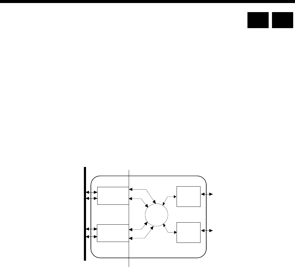
Module configuration 4-215
© 1993–2000 Jtec Pty Limited
Integrated Router Module (IRM)
The Integrated Router Module (IRM) is a multiport, multiprotocol router designed
to add Local Area Network (LAN) interconnection functionality. The IRM connects
LANs to other remote networks via the Wide Area Network (WAN) facilities
provided by the equipment.
The IRM comprises two conceptual parts:
•A Bridge/Router that supports the LAN interfaces and Bridging and Routing
functions
•A line module that provides the WAN interfaces and calling functions.
It provides up to two physical LAN ports on the front panel and four WAN ports on
the chassis backplane. This concept is illustrated below.
The IRM supports the following features:
•Fixed bandwidth
•On-demand calling
•Dynamic or static bandwidth management
•Automatic Backup and Restore
•Frame Relay WAN encapsulation.
Fixed bandwidth
A fixed amount of bandwidth is allocated to handle calls, regardless of traffic loads.
On-demand calling
A call is triggered when significant data is bound for an on-demand WAN port. When
the call is no longer required, the call is cleared. Significant data is defined as frames
routed or bridged to a single WAN port. These include Unicast frames generated by
the IRM.
dge
ute
WAN
Interfaces
r
External
LAN
Interface
External
LAN
Interface
WAN
Interfaces
A
B
Bri
Ro
IRM
Chassis
Backplane
RM CM

4-216 Integrated Router Module (IRM)
10003497.00 Rev.5
When no significant data (for a configured period) is bound for an on-demand WAN
port, the Bridge/Router releases any active calls associated with that WAN port.
While in this state, the Logical Port is not considered down and (pseudo-static) routes
are maintained. The Bridge/Router is then able to route traffic to a Logical Port even
though the Physical Port is disconnected. Spoofing is also provided so that host
sessions are not lost.
On receipt of significant data bound for an on-demand WAN port, the Bridge/Router
activates the WAN port. While this is occurring, any further traffic bound for the port
is buffered until the port is activated or the buffer overflows.
When a Group A port is used in an on-demand situation, bandwidths of up to
1984kbit/s can be used over the on-demand network connections that do not exhibit
a differential delay between bearer channels. In this case, you have the option of
using either static or dynamic bandwidth management of the on- demand connection.
Note The on-demand mode of the IRM cannot be used with the BCAM-ISO. You can use
multi-linking to achieve on-demand mode speeds greater than 64 kbit/s and up to 256 kbit/s
in networks that exhibit differential delay.
Dynamic bandwidth management
Dynamic bandwidth management refers to the ability to provide automatically
adjusted WAN bandwidth on the basis of preconfigured user traffic load
requirements. This applies to already active Logical WAN connections. The
mechanism does not clear or establish Logical WAN connections.
Static bandwidth management always uses the maximum configured speed (or as
close as possible) as the active WAN bandwidth.
Both the Line Module and Bridge/Router Module have control over certain
bandwidth management mechanism aspects.
Line Module Bandwidth Management
The Line Module dynamically manages bandwidth by adding and deleting channels
of a WAN port. The bandwidth increments are therefore in bearer speed steps. Hence,
bandwidth management within the Line Module domain relates only to Group A
ports that do not exhibit a differential delay between bearer channels. It does not
apply to Group B ports that only operate at a maximum of one channel.
When using Line Module dynamic bandwidth management, setting up WAN port
connections result in the connection of a single channel at the bearer speed. The setups
may originate from an XSPC, a user, or the Bridge/Router Module depending on how
the IRM is configured. As traffic demand varies, the WAN bandwidth increases or
decreases as the IRM at the calling party end connects and disconnects channels up
to the maximum configured speed.

Module configuration 4-217
© 1993–2000 Jtec Pty Limited
You can configure a utilisation and hold time for the up speed decision, and another
utilisation and hold time for the down speed decision. If the IRM detects that the
average utilisation over the hold period is above the threshold set for up speed, an
additional channel is connected. Likewise for down speed, if the IRM detects that the
average utilisation falls below the threshold set for down speed, a channel will be
disconnected. The last channel of the WAN port is not disconnected. Either the
transmitted or received data, whichever is the greater, is used for the utilisation
calculation.
Where two Group A ports are Multilinked, and the dynamic management
configuration on both ports are identical, the Line module will manage the bandwidth
by evenly distributing the load across the pair.
When using Linesets, you can configure a trunk such that channels are dedicated for
IRM traffic only. Thus you can configure committed minimum bandwidths for
dynamic (and on demand) WAN ports.
The Line Module statically manages bandwidth by either:
•accepting any speed, up to the maximum configured, for incoming calls: or,
•if possible, setting up the maximum WAN speed for outgoing calls.
Bridge/Router Module bandwidth management
The Bridge/Router Module dynamically manages bandwidth by connecting and
disconnecting Physical WAN ports (including Group B ports) that are multilinked
within one Logical Port. The bandwidth increments are therefore in configured port
WAN speed steps. This call mode is called Bandwidth on Demand.
As traffic demand varies, the WAN bandwidth increases and decreases by connecting
and disconnecting WAN ports. IRMs at either end of a point-to-point link attempt to
vary the Logical WAN bandwidth should they be configured to do so. The up-speed
and down-speed utilisation thresholds can be configured with a common hold time.
When these thresholds are out of limits for the common hold time, the IRM that
detects the transmitted data utilisation connects and disconnects the WAN ports
accordingly.
Dynamically managed bandwidths up to 256kbit/s are possible, without the use
ISO-BCAMs, over networks that do exhibit a differential delay between 64kbit/s
channels.

4-218 Integrated Router Module (IRM)
10003497.00 Rev.5
Backup and restore
In any calling mode the Bridge/Router Module may disconnect a WAN port
connection if either:
•the Logical Port fails to come up after 40s following a call setup: or,
•if an active Logical Port goes down.
This disconnect constitutes a failure in the primary connection path for a period of
30 seconds. Within this period, any subsequent outgoing call is made using the
Hotline number configured in the Line Module. Any call attempts after this period
will first retry the primary path.
Frame Relay
Frame Relay is supported locally through digital interfaces, such as the QDLM and
BCAM-ISO or remotely via trunk modules. It is only used with Group A WAN ports.
Notes
The IRM cannot run Frame Relay and PPP on different WAN ports. If PPP is enabled, Frame
Relay will not operate.
An IRM port that is configured to run Frame Relay applies ’User-side’ Frame Relay PVC
procedures. The device to which the IRM port is connected needs to run ’Network-side’ PVC
procedures.
If an IRM port is manually connected to a packet Port, the Packet Port must be configured to
use Flag Fill.
See the IRM Router Configuration Manual for more details.
Configuration
This section covers the basic configuration for the line module aspects of the IRM. To
configure the IRM for Routing/Bridging, refer to the IRM Router Configuration
Manual.
Configuration of the WAN ports is similar to any other line module. The WAN ports
interconnect B-channels to a LAN User Interface. If multiple B-channels are
configured via the WAN port, the settings of the first channel is normally applied to
all other channels. However, if required, B-channels can be configured individually.
See the Parameters section for details of line configuration.
Group configuration
The following parameters can be configured for both Group A and B. The groups
differ only in their maximum speed capabilities — Group A up to 1984 kbit/s and
Group B up to 64 kbit/s.

Module configuration 4-219
© 1993–2000 Jtec Pty Limited
Configuration defaults
Changing the configuration defaults
B-channel rate Only 64 kbit/s is currently available.
WAN speed The WAN speed specifies the speed at which the WAN port will be running for the
Bridge/Router. Group A and B both provide the same sub speed capabilities that is,
speeds less than 64kbit/s.
The sub- 64kbit/s speed capabilities include 48 kbit/s ITU-T (CCITT) framed and
n x 8 kbit/s non-ITU-T (CCITT) framed speeds: 8, 16, 24, 32, 40, 48, 56 kbit/s.
The 48 kbit/s ITU-T (CCITT) WAN speed is generally used for Subrate interworking
applications. A more common sub speed application involves non-ITU-T (CCITT)
framed sub speeds that are used with Subrate Virtual Lines to include either
compressed voice or other sub rate channels in one B-channel (see page 3-23 for more
information on Subrate Virtual Lines).
Speeds greater than 64 kbit/s are incremented in multiples of 64 kbit/s. That is, one
B-channel is required for each speed increment above 64kbit/s. For example,
1984 kbit/s requires the connection of 31 B-channels.
Note The DTM can provide up to 31 full B-channels in one link. One IPM link can only
provide up to 30 full B-channels.
On Demand Max
This enables you to select a WAN speed from a set of valid speeds. The set is the same
as that shown against the Fixed User Rate.
Static — Select this for on demand calls that are to be made at the selected speed. If
the IRM fails to negotiate all of the calls required to achieve the selected speed, it
accepts any calls that are successfully made.
Note When using On-demand mode, enable Auto Answer at both ends of the link and use
larger static bandwidths.This helps when both ends of a link require bandwidth at the same
time.
Parameter Default
B-Channel Rate 64 kbit/s Selected
WAN Speed On Demand Max —
Fixed User Rate 64k
Call Options Auto Answer Cleared
Semipermanent SPC Enable Cleared
SPC Label —
Hotline Hotline Cleared
XSPC Cleared
Number set —

4-220 Integrated Router Module (IRM)
10003497.00 Rev.5
Slow Dynamic — Select this to enable calls on a single Group A WAN or two
multi-linked Group A WANs to be made and cleared on the basis of traffic variation.
In this mode, the IRM is slower to make and clear calls. The calling party controls the
dynamic features. The slow dynamic default settings are as follows:
•Up Speed Utilisation = 75%
•Up Speed Hold Time = 12s
•Down Speed Utilisation = 30%
•Down Speed Hold Time = 60s
Pulse Dynamic — This setting has the same features as Slow Dynamic, but the IRM
is faster in making and clearing calls. The pulse dynamic default settings are as
follows:
•Up Speed Utilisation = 75%
•Up Speed Hold Time = 5s
•Down Speed Utilisation = 30%
•Down Speed Hold Time = 30s
Custom — This enables you to change the Threshold Utilisation and Hold Time for
the Up Speed and Down Speed settings to define your own dynamic calling regime.
The Custom Dynamic Setting dialog box shows the settings currently selected.
Notes When using ISDN, you should set the parameters to delay the disconnection of active
channels. This helps to minimise flag fall costs. Conversely, you should balance these costs
against the cost of the timed rates when the call is active.
When customising, be careful not to create call bouncing. This is when calls are made and
cleared continuously.
Threshold utilisation is based on the greater value of either transmitted or received data.
Fixed User Rate
This shows the available WAN speed. Select this parameter to accept the shown rate.
When this is selected, the Static, Slow dynamic, Pulse dynamic and Custom settings
are not available.
Call options The only call option is Auto Answer.
When enabled, the IRM does not require the bridge/router to respond before it
connects incoming calls. When disabled, the IRM does not automatically answer
incoming calls but notifies the network that the bridge/router is to be alerted first.
This ensures that the call is connected only if the bridge/router can use the call.
Semipermanent To set up a semipermanent connection from a WAN port, select SPC Enable and enter
the semipermanent label issued by your service provider.
For WAN speeds higher than 64kbit/s, SPC activation is configured on an BCAM-ISO
module and not the IRM. See page 4-222 for details on using the BCAM-ISO as an
IRM utility.
Note You should deactivate Hotline calls when SPCs are activated.

Module configuration 4-221
© 1993–2000 Jtec Pty Limited
Hotline To enable a WAN port to dial a Hotline number enter the Hotline Number and enable
the Hotline. (Entering the Subaddress, if required, can be done using Edit List
Configuration).
Note You should disable SPC connections when Hotlines are activated.
When XSPC is enabled, the device dials the Hotline number and continually redials
if the connection fails. This is available only when Hotline is enabled.
In On-demand mode, the Number Set is only used when the line module must
originate a call when:
•XSPC is enabled on the WAN
•a manual call is made from the Network manager
•in backup mode.
Notes When in backup mode, the next call retry uses the Hotline Number Set as the backup
number rather than the Bridge/Router’s original calling party number.
If backup is not required, the Hotline Number Set must be the same as the Bridge/Router’s
calling party number.
Outgoing TE Select the required TE for all the module’s lines. If you select Preferred or Exclusive,
you must then select the TE from the list of available TEs.
Port identification
A port is identified by its line number. Calls bound for an NT will be routed to an
IRM WAN port when the line number is matched with the incoming called party
number. Port line number configuration is achieved by assigning the appropriate IRM
WAN port lines as members of the desired lineset or Virtual Line identifiers. See
Linesets on page 3-17 and Virtual Lines on page 3-21 for more details.
Note If a TE is present and a base number has been defined, the line number matched will
be the incoming called party number - base number.
As well as the line number, the following parameters can be configured on a line by
line basis:
•ISDN subaddress line number suffix (optional)
•port ID label (for use in conjunction with the IPM CLI package)
•port name.
Backplane bandwidth allowance
The IRM uses backplane bandwidth dynamically. This means that backplane
bandwidth is allocated as required. For example, an IRM that has all four WAN ports
configured for 64kbit/s, is only allocated the four backplane timeslots that it needs.

4-222 Integrated Router Module (IRM)
10003497.00 Rev.5
Using the BCAM-ISO as an IRM utility
If an IRM Group A port uses a network that cannot provide a constant differential
delay between B-channels, an ISO standard B-channel Aggregation Module
(BCAM-ISO) is required. The BCAM-ISO performs the necessary channel sequence
alignment to aggregate (referenced to time) the multiple B-channels. Other common
terms used to describe this process are Inverse Multiplexing and ISDN Super Rate
Adaption.
See page 4-207 for the BCAM-ISO configuration details.
When configuring the IRM and BCAM-ISO to operate together, observe the following
points:
•Configure the IRM WAN speed first.
•Select Manual Connect (Backplane) in the BCAM-ISO configuration.
•After configuring the BCAM-ISO, ensure the status of the IRM WAN port is active.
If the status is not active, configuration is not correct.
•BCAM-ISO Mode 1 has no overhead channel with the disadvantage that no data
integrity checking takes place. If the data path is lost while the calls are active, the
IRM cannot automatically disconnect calls. You would need to manually
disconnect and reconnect the calls in this instance.
•BCAM-ISO Mode 3 provides data integrity checking but with the disadvantage
of the need for an overhead channel. If the data path is lost while calls remain
active, the BCAM-ISO can be configured to disconnect and re-establish the calls.
•The BCAM (AS 4064) cannot be used with the IRM.
Notes
•Link connections that do not exhibit differential delay problems (for example, calls going
through a DTM trunk or IPMs connected back to back) will not require the BCAM-ISO.
•SPCs do not guarantee constant differential delay between channels. Therefore, when
using SPC WAN speeds greater than 64kbit/s, the BCAM-ISO must be configured for
SPCs and provide a backplane connection to the IRM.

Module configuration 4-223
© 1993–2000 Jtec Pty Limited
Signalling Access Module (SAM)
The Signalling Access Module (SAM) can perform the functions of an inband
signalling node. An inband signalling network is created by interconnecting the
inband signalling nodes of all devices in the network. The SAM is only required for
Subrate Virtual Lines, and not TimeFrame VLs.
Note The SAM is not supported by the Resource Manager (RM).
Inband signalling provides an economical alternative to reliance on public ISDN
D-channel user-to-user messaging.
Inband signalling nodes can be interconnected by any of the following types of
communications links:
•packet-switched public data network via ISDN B-channel at 64 kbit/s
•64 kbit/s Channel, via an ISDN B-channel, or via any timeslot of a G.704 system
(except timeslot 0), or via an SDLM X.21 interface
•front panel X.21 DCE or DTE interface up to 64 kbit/s
•front panel synchronous V.24 DCE or DTE interface up to 38.4 kbit/s.
The number of communications links that can be connected to one device is limited
only by the availability of physical connections, and other hardware limitations.
The SAM front panel can be configured as a DCE (Data Circuit Equipment) or DTE
(Data Terminal Equipment) as defined by ITU-T (CCITT) recommendations. It is
fitted with either an X.21, V.24 or V.35 interface on the front panel.
For further information on inband signalling, refer to page 3-43, Inband signalling
facility.
For information on using the SAM for inband signalling see page 5-43 of the
Applications section.
Configuration
Connecting multiple SAMs in a single node
We recommend that you connect channel B2 of the first SAM to channel B1 of the
following SAM. This ensures that channel B1 of the first SAM is always connected to
the Control Module inband channel, and B2 is connected to other SAMs in the chassis.
The following shows the connection arrangement between a CM and three SAMs in
the same node:
CM inband Ch --->B1-B2--->B1-B2--->B 1
CM

4-224 Signalling Access Module (SAM)
10003497.00 Rev.5
The router table entries of the SAM can be configured as normal, but with the
precaution that the table is constructed to direct those calls that do not match an entry
to channel B2. This allows the unmatched calls to be routed to the remaining SAMs.
The following table shows an example setup for three SAMs:
Notes
The support of multiple SAMs in a single node may cause slight delays in the response of the
inband signalling information.
When two SAMs are used in the same chassis, incoming calls will fail if all lines on the first
SAM module are busy. The incoming calls are not redirected to the second SAM. To avoid
this, configure outgoing calls to start on the second SAM, leaving some ports free on the first
SAM module for incoming calls.
SAM Line Control
Edit Line There are no defaults on this setting.
Configure Select Router tables. This enables you to set up the inband signalling network for the
module you have already selected.
Configure Inband Signalling Routing Table
By selecting Add routes, you are presented with Configure Inband Signalling
Routing Table. This offers you the possibility of selecting Destination Address,
Primary Routes, Secondary Routes, and Configured Addresses.
Each route is identified by a set of three numbers, together with a description. The
first member of the set designates the module slot position, the second, the interface
type and the third, the line or channel.
You should ensure that your primary route selection does not overlap with your
secondary route selection, for a particular destination.
CM Router Table 93640098
0188
04-09
D1
D2
inband
SAM1 04111
042688
05-09
B3
B4
B2
SAM2 05123
055555
052-053
06-09
B3
B4
B8
B2
SAM3 08
09 B5
B2

Module configuration 4-225
© 1993–2000 Jtec Pty Limited
Inband Signalling Routing Table defaults
Default use D (or)
B-channel B-channel.
SAM channel idle
holding time 30 secs.
Destination
Address None.
Primary Routes None.
Secondary Routes None.
Configured
Addresses None.
Changing Signalling Routing Table defaults
Before building a routing table, you must supply the Destination address and, if more
than one address is to be routed, its range. To each address, or range of addresses, a
primary route must be attached.
Default use D (or) B
channel These are relevant to the CM-SAM routing table configuration. If a called number is
not listed in the routing table, the CM-SAM router makes the call directly to the
destination using whichever default channel is selected.
SAM channel idle
holding time This has a range from 0 to 2550 secs. The default is 30 secs. When enabled, the channel
is held open for the specified time even when no activity is detected.
Area code Enter the Area code without the leading zero.
Transit call line
number A D-channel NMS call can be made into a router that has been programmed with this
number. This is then forwarded on to a B-channel NMS call.
Destination
Address Insert the minimum destination number of the range in the Min/Only field. If there
is only one destination number, enter it here. Enter the maximum number of the range
in the Max field.
Primary Routes After inserting a destination address, highlight the selected Primary Route from the
list appearing in the window. Then select Add.
Secondary Routes Highlight the selected Secondary Route from the list appearing in the window, if
needed. Then select Add.
Configured
Addresses The window displays a list of configured addresses, using the Primary Route and
Secondary Route settings you selected.
To delete a Routing Table entry, highlight it in the Configured Addresses table, and
press Delete. To eliminate the table, select Delete All.

4-226 Signalling Access Module (SAM)
10003497.00 Rev.5
ISDN Interface — Call Establishment Modes
The following table shows Call Establishment Modes default settings for each
channel.
Call Establishment Modes defaults
Changing Call Establishment Modes defaults
The settings for these parameters control the way in which calls are made. You can
set up the following call types:
Semipermanent
(where available) Enter the semipermanent number in the Label parameter and select Enable. You
should also clear the Hotline checkbox.
Member of Subrate
Virtual Line or
manually connected
Select Yes if the line is a part of a Subrate Virtual Line or manually connected. Enter
the number in the Label parameter. You should also clear the Hotline checkbox.
Hotline Enter the Hotline number for the channel and enter a subaddress, if required. Select
Enable. You should also clear the Semipermanent or Member of Subrate Virtual line...
checkbox.
Select XSPC to enable a Switched Semipermanent Connection if required. You can
only select this if a Hotline is enabled.
Don’t use for I/C
manager calls Select this to prevent the SAM channel being used for incoming OmniVision calls.
ISDN Internal Control
Restriction Select None (default), In only, Out only or Disable.
Operation (Front
panel only) Select DCE or DCE.
Outgoing TE Select the required TE. If you select Preferred or Exclusive, you must then select the
TE from the displayed list. This setting affects all the module’s lines.
Parameter Default
Semipermanent
(where available) Enable Cleared
Label —
Subrate Virtual Line
member or manually
connected
Enable Cleared
Label —
Hotline Enable Cleared
Number —
XSPC Cleared
Subaddress —-
Call Control Don’t use for I/C manager calls Cleared

Module configuration 4-227
© 1993–2000 Jtec Pty Limited
Frame Switch Module (FSM)
The Frame Switch Module (FSM) is a Frame Relay switch with a built-in access router.
It is available in two variants:
•FSM-15 — supports up to fifteen remote connections
•FSM-30 — supports up to thirty remote connections.
The FSM terminates remote devices to a LAN using the PPP protocol. It does this via
an ethernet 10baseT port or to an external router via a Frame Relay port using X.21
or V.35 access. The Frame Relay port supports access through public networks or
direct connect.
The FSM supports an external RADIUS Server for access control and accounting
purposes. PAP and CHAP access control protocols are also supported.
Remote access devices can be:
•64k ISDN service
•analog modems when used with a Digital Modem Module (DMM)
•9600 bit/s GSM data.
The FSM is NMS-configurable using OmniVision. The router is configured directly
from the front panel port or via a connected LAN.
Configuration
Call routing
Call Routing is configured in the same way as all other modules in the chassis. FSM
lines can be placed in linesets or given individual line numbers. To configure linesets,
see Linesets on page 3-17.
To configure individual line numbers select the module on the NMS front panel
display.
Outgoing Calls
Outgoing calls can be made from FSM ports by configuring a Hotline number and
enabling Hotline mode on the port. The call can be initiated using the NMS or by
enabling XSPC mode on the FSM port.
Outgoing calls use the Bearer and LLC as configured for the port. Bearer should be
set to 64K Unrestricted Digital with no Octet 5. LLC should be set to 64K
Unrestricted Digital with CCITT Rate Adaption enabled if anything other than 64k
is required. Octet 5a can then be programmed with the desired data rate and
synchronous or asynchronous settings.
Note In this release, modems cannot be used in outgoing calls as the DMM always has the
modems in answer mode, and not originate mode.
RM CM

4-228 Frame Switch Module (FSM)
10003497.00 Rev.5
Manual connections
Manual connections can be made between two FSM ports or between an FSM port
and another port such as that of a DLM or E1M. The connection is made using the
NMS manual connection facility. In this release, manual connections are digital, that
is, you cannot use modems.
The same rules apply for configuring manual connection LLC and Bearers as in
Outgoing calls above. However, if you are making a manual connection between two
FSM ports, you should programme both ports (rather than just the originator as is
the case in outgoing calls). Both ports should have the same configuration settings.
FSM Line Control
FSM configuration
Port address This is a unique IP address that is assigned nominally to the LAN port, but is also
used as the Router’s own address for Telnet, TFTP and so on. The address is entered
in the form 1.2.3.4.
The FSM does not support IP Addresses with an octet of zero (.0) – as RFC950 specifies
this is an invalid address. For example, the FSM does not support the address
172.16.0.80 with subnet mask 255.255.255.0.
Route configuration The Static Route is entered as an IP address in the form 1.2.3.4. The default setting is
0.0.0.0 which indicates that there is no Default Route. If no route is entered the FSM
will learn the route from another router in the network.
To configure a route, select the direction of the route, that is, To Gateway or To Port
(PPP or Front panel). If using the gateway, enter an appropriate address. If using the
PPP or Front panel port, enter a suitable port number.
You can configure further Static Routes by manually creating and editing a USER.INI
file. The file, once created can be uploaded to the FSM using TFTP. Once the FSM has
been restarted, the new static routes are enabled.
Enter the additional routing information in the IP Routing Section. If this does not
exist, enter the following line in the USER.INI file:
[[User IP Routing = Section Start]]
The general syntax for a static route is:
target, gateway, mask, metric, port number
The details of this depend on whether the route is to an attached network (LAN), or
to the Point-to-Point protocol (PPP) or Front panel Frame Relay port. If the route is
to an attached network, set the gateway to the appropriate address and the port
number to 255.
If the route is to one of the WAN links, set the gateway to 000.000.000.000 and set the
port number to 1-30 for the respective PPP ports, or 31 for the Frame Relay front panel
port.
Below are two example static routes:
Example 1
This routes all traffic to subnet 192.123.42.0 via gateway 192.123.43.254 with metric 1.
[[ User IP Routing = Section Start ]]
IP Static Route Table Entries = ;192.123.042.000, 192.123.043.254,
255.255.255.000, 01, 255

Module configuration 4-229
© 1993–2000 Jtec Pty Limited
Notes The line beginning ’IP Static Route’ and ending’ , 255’ should all be on one line.
The semicolon (;) is positioned before the target address and all addresses are three digits with
leading zeroes.
Example 2
The second routes all traffic to subnet 192.123.42.0 via PPP port 13 with metric 2:
[[ User IP Routing = Section Start ]]
IP Static Route Table Entries = ;192.123.042.000, 000.000.000.000,
255.255.255.000, 02, 013
Domain Name
Server (DNS) The DNS is not used by the FSM, but can be sent to remote dial-in users as part of the
PPP negotiation. If the DNS is set to a value, other than 0.0.0.0, and a remote PPP
requests a DNS, the entered address is supplied as the Primary DNS (PPP Option 129).
Note This is not supported by all PPPs.
PPP Idle timeout This parameter sets an inactivity timeout after which the call is terminated. If the
timeout is set to Off, or On with zero minutes, PPP sessions will continue indefinitely
or until the user terminates the session. If the timeout is set to On with a setting of
between 1 and 240 minutes, the session will terminate after that many minutes of
inactivity. Inactivity is defined as no IP traffic.
IP Addressing and Routing
The WAN ports must be assigned an IP address. Each of the 31 WAN ports can run
Numbered or Unnumbered links. Unnumbered is the default.
If using Numbered links, each WAN link requires its own subnet. The remote and
local ends of the link are assigned addresses within that subnet, and when the port
is used, the FSM creates a route for the entire subnet.
When unnumbered links are used, only the remote end of the link has an IP address.
The remote link becomes a host route, using the FSM LAN port as a gateway address
when the port is used. These addresses do not have to be on a unique subnet.
Select the line to be configured and make the following entries.
Line number Enter the line number.
Typically, Bearer Capability and Low Layer Compatibility configuration is not
required for the FSM. The FSM accepts a wide range of call types, and uses modems
or different rate adaption schemes to match the incoming call.
Notes
If calls are being rejected due to incompatible Low Layer, disable LLC Checking for incoming
calls.
When operating over a DASS-2 network, Telephony must be enabled in the Higher Layer
Compatibility for each FSM line being used.

4-230 Frame Switch Module (FSM)
10003497.00 Rev.5
FSM port control
IP Address Enter the remote IP address. This should only be used when the remote device does
not have an IP address configured, and is to be assigned an IP address by the FSM.
Note The remote address can also be assigned from RADIUS. If you are going to use
RADIUS, or the remote device already has an IP address, leave this field as 0.0.0.0.
The FSM does not support IP Addresses with an octet of zero (.0) – as RFC950 specifies
this is an invalid address. For example, the address 172.16.0.80 with subnet mask
255.255.255.0. is not supported.
To change from the default Unnumbered operation, choose PPP or Frame relay as
required and select the Setup button. This provides access to More port settings.
IP
Unnumbered Link If this is selected, the Local Address field is automatically set to 0.0.0.0, and the Mask
field to 255.255.255.0. These fields are disabled.
Numbered Link If you select this option, the Local Address should be set to an appropriate address.
The Mask field defaults to 255.255.255.0, but can be changed to suit your
requirements.
You should use the following user.ini configuration in the [[ User IP Routing
= Section Start ]] section when configuring numbered WAN links:
Convert the WAN port IP address to a net route in the routing table by entering
the following line in user.ini:
IP Port Remote Mask = 01, 255.255.255.0
where '01' is the port number and '255.255.255.0' is the mask of the WAN port.
Create a static route over a numbered WAN link, by adding the following lines to
user.ini:
IP Port Unnumbered Link = 01, disabled
IP Static Route Table Entries =
;172.21.224.100,192.195.112.1,255.255.255.252,02,255
where the format for the first line is port, enabled/disabled and the second line
is target, gateway, mask, metric, port.
Use Proxy ARP This can be used with unnumbered links. When selected, the front panel LAN port
performs ARP (Address Resolution Protocol) on behalf of the WAN port. The Ethernet
Address of the LAN port resolves the IP addresses of the LAN port and any WAN
ports that have this proxy ARP enabled.
Enable RIP RIP can be enabled on a port by port basis. The default is off. This is recommended
for WAN links.
RIP can be disabled globally by including the line IP RIP = disabled in the [[
User IP Routing = Section Start ]] section of the user.ini file.
Note If a large number of routes are present in the network, and RIP is enabled, performance
can be seriously degraded. This is because the routes will all be propagated down the WAN
link every 30 secs.

Module configuration 4-231
© 1993–2000 Jtec Pty Limited
Multilink PPP
Multilink PPP is a extension to the PPP protocol that allows a number of PPP links
to be combined to form effectively one larger link. The collection of PPP links is called
a ‘bundle’. Up to four Lines are supported in a bundle, providing a maximum data
rate of 256kbit/s. A PPP bundle takes its IP addresses and routing information from
the first port in the bundle. Bundles must consist of contiguous ports in the FSM.
A Multilink bundle is identified using the Multilink Endpoint Identifier. This is a
unique identifier assigned to all the ports in the bundle. A number of different types
of identifier are allowed. The FSM uses a 4 byte identifier made up of:
•for unnumbered operation – the port number of the start of the bundle followed
by the last 3 bytes of the LAN IP address, or:
•for numbered operation – the local IP address of the bundle.
This is carried out by the FSM and does not require any configuration.
Once a bundle is created and one or more of its ports are active, IP packets are divided
up and sent as fragments across the different members of the bundle and recreated
at the destination.
Configure Multilink PPP
A port can be set to one of the following:
•Multilink (MP) Off
•MP Start of Bundle, or
•MP Bundle Member.
To configure a bundle, set the first (that is, the lowest port number of the bundle) to
MP Start of Bundle and subsequent ports to MP Bundle Member. The bundle
continues until a port is configured as MP Start of Bundle again or MP Off. Then
configure the IP addressing on the MP Start of Bundle port.
Non-fragmented Multilink PPP packets are always sent down the member of the
bundle which is marked as the 'Start of the Bundle'. This means that to get the most
efficiency from the Multilink PPP link you should always make the highest speed
link the 'Start of the Bundle'.
Note If Multilink is being run across TimeFrame and a TDM link then the TDM link should
always be made the ’Start of the Bundle’.
Ports may be used for both Multilink and normal PPP operation. All ports in a bundle
should have IP addresses and Authentication configured as desired. To receive a
Multilink call, the caller must support the Multilink MRRU and Multilink Endpoint
Discriminator options in their PPP. If a port receives a Multilink call it will operate as
part of the Multilink bundle. If neither of the above options is supported, the port
will revert to non-multilink operation for the duration of the call.
Note When Multilink PPP configuration has been changed, the FSM must be restarted to
incorporate the changes.

4-232 Frame Switch Module (FSM)
10003497.00 Rev.5
Compression
The FSM supports two forms of compression:
•Stac LZS PPP Data Compression implementing the PPP Compression Control
Protocol (CCP) and
•TCP header compression implementing Van Jacobson Compression (VJC).
Compression (CCP) If CCP is enabled on an FSM port, the FSM will attempt to negotiate compression
with the remote user. The FSM only supports Stac LZS compression, but supports all
the different modes such as LCB, CRC, sequence number and extended sequence
number. This is compatible with Win95, Win98, WinNT, Internet Explorer Dialler and
Cisco 750 series routers amongst others.
Internet Explorer Dialler enables CCP by default. Win95 needs ‘Enable Software
Compression’ set in the Dialup Networking options.
Compression (VJC) If VJC is enabled on an FSM port, the FSM will attempt to negotiate the use of Van
Jacobson TCP header compression on the link. If successful, the FSM will compress,
and allow the reception of compressed headers on TCP traffic, for example, telnet, ftp
and http.
Note Where Compression is used in conjunction with Multilink PPP, all ports in a bundle
should be set to the same compression options.
In order to have compatibility with certain ISDN Terminal Adaptors, the FSM Address and
Control Field Compression (ACFC), and Protocol Field Compression (PFC) are disabled.
These compression fields are associated with PPP.
Frame Relay
Frame Relay DLCI See Frame Relay port on page 4-235 for more information.
Comms
Set the clock rate and DTE/DCE selection for the front panel port. DCE provides
clock, DTE expects it. The clock rate should be a multiple of 64 between 64 and 2048
(Kbit/s).
RADIUS
A RADIUS server can be used for both Authentication and Accounting. A local
RADIUS-style operation is also available and can be accessed using a local password.
file. To configure RADIUS for remote or local operation, carry out the following:
Local Select this to enable local operation. This uses the password file stored in the FSM. If
the password file is encrypted, check the Local password file is encrypted checkbox,
and type the secret in the Secret field.
Remote Select this to enable the remote RADIUS Server. Type its IP address in the IP Address
field. Type the secret in the Secret field.
RADIUS accounting
enabled Select this to enable RADIUS accounting. This sends the appropriate RADIUS
accounting start and stop messages to the server. If local operation is selected, the
start and stop messages are printed from the monitor port.

Module configuration 4-233
© 1993–2000 Jtec Pty Limited
Login and authentication
The FSM supports bi-directional authentication for PAP and CHAP. This means that
the FSM can Authenticate and be authenticated at the same time.
For Login, authentication is asymmetrical, that is, it challenges remote users. A
remote user must respond accordingly. The FSM does not respond to a challenge from
the remote user.
Authentication for each of the PPP ports is configured with each line configuration.
The following settings are all valid:
All Authentication
off (none selected) No authentication is performed. PPP starts as soon as the port is used.
Login on, PAP and
CHAP off Only Login authentication is performed. When the port is used, the FSM sends a
configured text message followed by the configured login prompt. The FSM collects
the password and name and presents them for authentication (local or RADIUS).
When these are accepted, PPP is started.
Note User names less than four characters long are ignored. This allows some types of
menu-expecting scripts that send a number followed by a carriage return, followed by a name
and another carriage return, to operate correctly.
Login off, PAP or
CHAP on Only PAP or CHAP authentication is performed. When the port is used, the FSM
starts PPP. LCP negotiation of PAP and CHAP authentication is requested. If both of
these are refused, the call is cleared. If one is accepted, the FSM will authenticate the
remote user between LCP and NCP negotiation phases using whichever is accepted.
If the authentication is responded to correctly, the call proceeds, otherwise it is
terminated.
Login on, PAP or
CHAP on This is the most flexible configuration. PAP, CHAP or Login are acceptable. The FSM
sends the login prompt as soon as the port is used. If PPP is detected, rather than a
name, the FSM starts PPP and attempts to negotiate PAP or CHAP authentication.
Note When PAP or CHAP is selected, the FSM accepts either, but will try the selected one
first.

4-234 Frame Switch Module (FSM)
10003497.00 Rev.5
RADIUS attributes
The FSM sends the following RADIUS attributes:
Authentication Request Using PAP or Login
•User-Name
•User-Password
•NAS-IP-Address
•NAS-Port
•Service-Type
•Framed-Protocol
•Framed-IP-Address
•Framed-IP-Netmask
•Framed-Compression
•State
•Called-Station-Id
•Calling-Station-Id
Authentication Request Using CHAP or Login
•User-Name
•CHAP-Password
•NAS-IP-Address
•NAS-Port
•Service-Type
•Framed-Protocol
•Framed-IP-Address
•Framed-IP-Netmask
•Framed-Compression
•State
•Called-Station-Id
•Calling-Station-Id
•CHAP-Challenge

Module configuration 4-235
© 1993–2000 Jtec Pty Limited
Accounting Start
•User-Name
•NAS-IP-Address
•NAS-Port
•Called-Station-Id
•Calling-Station-Id
•Acct-Status-Type
•Acct-Session-Id
Accounting Stop
•User-Name
•NAS-IP-Address
•NAS-Port
•Called-Station-Id
•Calling-Station-Id
•Acct-Status-Type
•Acct-Delay-Time
•Acct-Input-Octets
•Acct-Output-Octets
•Acct-Session-Id
•Acct-Authentic
•Acct-Session-Time
•Acct-Input-Packets
•Acct-Output-Packets
•Acct-Terminate-Cause
Frame Relay port
You can configure one DLCI for the Frame Relay port. Enter the DLCI in Hexadecimal
in the range 30 to 916. The clock rate and the DTE/DCE selection for the front panel
port can also be configured. DCE provides clock, and DTE expects to receive clock.
Clock rate should be between 64 and 2048 kbit/s in multiples of 64 kbit/s.

4-236 Frame Switch Module (FSM)
10003497.00 Rev.5
FSM files
The FSM has a flash memory file system with a capacity of 3.84 MB. The system uses
compressed binary files. The FSM requires the following files for operation:
•fsmvxxxx.bin — Main operational binary
•fsm.ini — Main default configuration file.
Note These files and filenames should not be altered.
The following files are optional:
•user.ini — Extra configuration items (in fsm.ini file format)
•prelog.txt — displayed before login, when ascii login is configured. This is a plain
text file, up to 1K. The default is Frame Switch Module Version x.xx
•login.txt — displayed as a login prompt. the default is login:. The file should be
on one line with no carriage return or line feed at the end
•password.txt — Displays as the password prompt. The default is password:. The
file should be on one line with no carriage return or line feed at the end
•postlog.txt — displays after a successful login. This a plain text file up to 1k in
size. The default is Login Accepted, now starting PPP
•password — This is a data file used for local password verification if the remote
RADIUS is not enabled. It has the format:
name:password
name2:password2
The password can be plain text or MD5 encoded. This is configured from the
RADIUS Settings dialog. If encryption is selected, the passwords are stored in this
file as 16 character MD5 digest strings of the actual passwords using the RADIUS
Secret.
USER.INI file
This section details the parameters than can be added to the FSM USER.INI file to
change the configuration of the IP Router and PPP. Note that after changing any
configuration in USER.INI, you must reset the FSM for the changes to take effect.
We advise that the USER.INI parameters listed below are changed by personnel with
a good understanding of networking principles. You can use the default parameters
in most cases.
Note Lines starting with // in USER.INI are treated as comment lines and are not
processed by the FSM.

Module configuration 4-237
© 1993–2000 Jtec Pty Limited
Static Routes
If you require more than one static route, the extra static routes must be added in the
USER.INI file.
The syntax for static routes is:
IP Static Route Table Entries = ;Target, Gateway, Mask, Metric, Port
Number
There are two methods of entering a static route:
•Set the Gateway parameter to 000.000.000.000 and specify the correct Port
Number where 000 is the Ethernet Port on the FSM, 001 to 030 are the thirty PPP
WAN ports and 031 is the X.21 or V.35 port on the FSM Front Panel.
•Set the Port Number to 255 and specify a remote gateway connected to a local
port.
In both cases the Metric should be the correct number of hops to the target.
The static routes must be added to the following section in USER.INI.
[[ User IP Routing = Section Start ]]
Example:
[[ User IP Routing = Section Start ]]
// Create a Static Route to network 172.21.224.0 using the X.21/V.35
Front
// Panel Port with a Metric of 1
IP Static Route Table Entries = ;172.21.224.0, 000.000.000.000,
255.255.255.000, 01, 031
// Create a Static Route to network 172.21.16.0 using the Ethernet Port
// with a Metric of 2
IP Static Route Table Entries = ;172.21.16.0, 000.000.000.000,
255.255.255.000, 02, 000
// Create a Static Route to network 172.21.100.0 using PPP WAN Port 1
// with a Metric of 2
IP Static Route Table Entries = ;172.21.100.0, 000.000.000.000,
255.255.255.000, 02, 001
// Create a Static Route to network 172.21.200.0 via Gateway
192.195.118.10
// with a Metric of 3
IP Static Route Table Entries = ;172.21.16.0, 192.195.118.010,
255.255.255.000, 03, 255

4-238 Frame Switch Module (FSM)
10003497.00 Rev.5
IP Port Address Masks
To set the IP Port Address Mask (subnet mask) of each IP port you must add the
following line to the USER.INI file.
IP Port Address Mask = Port Number, Subnet Mask
Where the Port Number is 00 for the FSM Ethernet Port, 01 to 30 for the thirty PPP
WAN Ports and 31 for the FSM X.21/V.35 Front Panel Port.
Each port has a default mask of 255.255.255.0 if no line is specified for that port
in USER.INI.
The mask must be added to the following section in USER.INI.
[[ User IP Routing = Section Start ]]
Example
[[ User IP Routing = Section Start ]]
// Subnet Mask of 255.255.255.0 for the Ethernet Port
IP Port Address Mask = 00,255.255.255.000
// Subnet Mask of 255.255.255.252 for PPP WAN Port 1
IP Port Address Mask = 01,255.255.255.252
// Subnet Mask of 255.255.255.0 for the X.21 / V.35 Port
IP Port Address Mask = 31,255.255.255.000
Globally Enabling and Disabling RIP
You can globally enable or disable the Routing Information Protocol (RIP) in the FSM
by using the following line in USER.INI. Note that RIP is enabled by default if the IP
RIP = line is not present in USER.INI.
IP RIP = disabled
or
IP RIP = enabled
Add this line to the following section in USER.INI.
[[ User IP Routing = Section Start ]]
Example
[[ User IP Routing = Section Start ]]
IP RIP = disabled

Module configuration 4-239
© 1993–2000 Jtec Pty Limited
or
[[ User IP Routing = Section Start ]]
IP RIP = enabled
PPP Maximum Number of Configuration Requests
You can add this parameter to the USER.INI to change the number of PPP
configuration requests that the FSM sends before realising that there is no device
responding on the other end. The call is terminated at this point. If you do not enter
this line the number of attempts is defaulted to 86400.
PPP Maximum Number Of Configuration Requests = Attempts
Where Attempts has a valid range of 10 to 86400.
Add this line to the following section in USER.INI.
[[ User PPP Device Driver = Section Start ]]
Example:
[[ User PPP Device Driver = Section Start ]]
// Set the number of configuration requests to 33600
PPP Maximum Number Of Configuration Requests = 33600
Multilink PPP Parameters
You can use the following lines to change the parameters associated with Multilink
PPP.
MP Small Packet Length = Length
This line sets the minimum packet length (in bytes) at which packet fragmentation
over Multilink occurs. Valid values are 64 to 512. If you do not specify this line it
uses a default value of 128.
MP Stall Timeout = Timeout
This line sets the time (in seconds) before the Multilink PPP declares a packet
fragment lost and discards all received fragments of the packet. Valid values are 3 to
10. If you do not specify this line a default value of 5 seconds is used.
These parameters are added to the following section in USER.INI.
[[ User Multilink PPP Driver = Section Start ]]

4-240 Frame Switch Module (FSM)
10003497.00 Rev.5
Example
[[ User Multilink PPP Driver = Section Start ]]
// Set Fragment Packet Length to 128
MP Small Packet Length = 128
// Set Packet Fragment Discard time to 5 seconds
MP Stall Timeout = 5
PPP IPCP Parameters
The FSM supports the configuration of a number of PPP IPCP parameters in the
USER.INI file. These are Primary DNS (Domain Name Server), Secondary DNS,
Primary NBNS (NetBIOS Name Server) and Secondary NBNS.
You can configure the Primary DNS parameter using the FSM Line Control dialog
in OmniVision. The rest of the parameters are configured in USER.INI as described
below. If you do not add these parameters to USER.INI no NBNS or Secondary DNS
is provided during PPP negotiation.
PPP Port Remote Option = Port Number,IPCP,Secondary
DNS,131,Auto,Negotiation Not Required,Not Negotiable,IP,Secondory DNS
IP Address
PPP Port Remote Option = Port Number,IPCP,Primary
NBNS,130,Auto,Negotiation Not Required,Not Negotiable,IP,Primary NBNS
IP Address
PPP Port Remote Option = Port Number,IPCP,Secondary
NBNS,132,Auto,Negotiation Not Required,Not Negotiable,IP,Secondary
NBNS IP Address
Where Port Number is 00 for PPP WAN Port 1 through to 29 for PPP WAN Port 30.
Note You must enter the IP Addresses in this field in reverse. For example, an address of
192.195.112.13 is entered as 013.112.195.192.

Module configuration 4-241
© 1993–2000 Jtec Pty Limited
Add these parameters to the following section in USER.INI.
[[ User PPP Device Driver = Section Start ]]
Example
[[ User PPP Device Driver = Section Start ]]
// Set the secondary DNS as 192.195.112.8 for PPP WAN Port 1
PPP Port Remote Option = 00,IPCP,Secondary DNS,131,Auto,Negotiation
Not Required,Not Negotiable,IP,008.112.195.192
// Set the primary NBNS as 192.195.112.2 for PPP WAN Port 5
PPP Port Remote Option = 04,IPCP,Primary NBNS,130,Auto,Negotiation Not
Required,Not Negotiable,IP,002.112.195.192
// Set the secondary NBNS as 192.195.112.13 for PPP WAN Port 5
PPP Port Remote Option = 04,IPCP,Secondary NBNS,132,Auto,Negotiation
Not Required,Not Negotiable,IP,013.112.195.192
Telnet and Virtual Terminal
The FSM has a built in Telnet Server that allows various control and monitoring
functions to be performed remotely. It can be used with most Telnet clients. To access
FSM Telnet connect from a Telnet client program on a local or remote IP addressable
system to the FSM’s main IP address. Once connected a login: prompt displays. Type
the name and password.
The default name and password for an unconfigured system is either:
•root for the name and Jtec for the password, or
•admin with no password <enter>.
These can be changed from within the Telnet operation.
If the name and password is accepted, the FSM:telnet> prompt is displayed. The
FSM also supports the Virtual Terminal which can be accessed from OmniVision by
clicking the right mouse button over the selected FSM and choosing Virtual Terminal.
The Virtual Terminal does not prompt for a user name and password, and goes
directly to the FSM:telnet> prompt.

4-242 Frame Switch Module (FSM)
10003497.00 Rev.5
The following commands can be entered at the FSM:telnet> prompt using either
the Telnet client or the Virtual Terminal:
•dir — Show directory of flash file system
•ls — Same as dir
•ren oldfile.ext newfile.ext— Rename a file in the flash file system
•mv oldfile.ext newfile.ext — Same as ren
•del filename.ext — Delete a file
•rm filename.ext — Same as del
•type filename.ext — Display a (text) file (does not support files larger than
8 Kbytes)
•cat filename.ext — Same as type
•run [xxx.gz]— With no following parameters, this shows the currently active
program. When used with a filename (typically.gz) this sets the program that will
be run next time the system reboots
•reboot [now]— This will cause (if the now is also given) a system reboot. This
is delayed for 20 seconds to give time for the FSM to clear all calls and log them
with the Accounting server
•user [add name password] and user [delname]— With no parameters,
this lists currently authorised names and passwords for the Telnet server. To add
a new one, use user add name password. To delete an unwanted one, use
user delete name. If all users are deleted, the system will default back to the
default ones. The default one can be deleted using user delete root
•time — Set or display system time. Use time to display it or time hh:mm:ss (24
hour clock) to set it
•date — Set or display system date. Use date to display it or date dd:mm:yy
(NOT mm:dd:yy) to set it
•who — Lists who is currently logged in on what port since what time
•history n — Shows history of logins. Lists port number username, login time,
duration and numbers of octets sent and received
history 10 shows the first 10 entries in order of logoff time.
history -42 shows the last 42 entries in reverse order of logoff time. The FSM
will store the 1000 most recent sessions. This is not intended for accounting
purposes and is volatile (i.e. lost when rebooted)
•hostname — enables you to set the hostname of the FSM.
•naughty n — Shows list of bad login attempts (i.e. those that fail authentication.)
Lists name, port and time. The FSM will store the 1000 most recent attempts. This
is volatile
•notrace — Turns off all tracing and reporting. This can be used after diagnostic
traces have been set and ensures that performance will not be impacted by
unnecessary tracing that has been inadvertently left turned on
•router — See Router below
•ping <port number> <IP address to ping> — <port number> is 0
for the FSM LAN port, and 1 to 30 for the FSM WAN ports. <IP Address> is
entered in dotted decimal format
•tftp — See TFTP below
•help — List these commands
•? — Same as help

Module configuration 4-243
© 1993–2000 Jtec Pty Limited
•logout — Leave Telnet
•exit — Same as logout.
Router
Enter Router mode by typing router at the FSM:telnet> prompt. This displays
the FSM:router> prompt. Enter Router commands using a natural language type
interface. A limited set is shown here:
show stack ip route Shows routing table
cache Shows routing cache
protstats Shows protocol stats
portstats Shows port stats
arptable Shows the arp resolution table.
Diagnostics
A useful feature of the FSM is the ability to selectively trace protocol activity on any
or all of the LAN or WAN ports. The following commands are available from the
FSM:router> prompt:
set port ppp nn trace off
set port lan 1 trace short
set port fr1 trace medium
long
decode
where:
•nn is the PPP Port number from 1 to 30.
•off means disable.
•short means a single line display for each packet sent or received in the following
format:
TX PPP P1 L26
This means that the FSM has sent a packet out of Port 1, its length is 26 bytes.
•medium displays the same first line and also adds the first 16 bytes in hexadecimal.
the format is:
RX PPP P1 L26
FF 03 C0 21 01 03 00 08
•long displays the same first line but the entire packet is in hexadecimal.
•decode is available for PPP only. This performs a full decode of the PPP packet.
For example:
RX PPP P1 L26
LCP Configure-Request ID=3 Len=12
Authentication-Protocol Len=5 C22305
Magic-Number Len=6 01020304
and so on...
Note Be careful to turn any traces off again or performance will be degraded.

4-244 Frame Switch Module (FSM)
10003497.00 Rev.5
Router commands may also be used from the front panel monitor port. This is done
by prefixing the command with ur. For instance, to show the IP routing table, type:
ur show stack ip route
To quit Router operation and return to FSM:telnet>, type exit.
TFTP
TFTP is used to upload and download program files and configuration files. TFTP is
a client application which requires a TFTP server to be available with the required
files accessible. The TFTP server must be IP addressable by the FSM, and its IP address
must be known. DNS lookup is not supported.
To enter TFTP mode type tftp [aaa.bbb.ccc.ddd] at the FSM:telnet>
prompt. This displays the FSM:tftp> prompt. The following commands can be
used:
•connect aaa.bbb.ccc.ddd — Use TFTP server at IP address aaa.bbb.ccc.ddd
•get filename.ext — Upload the file filename.txt from the TFTP server and
store it in the FSM flash file system
•put filename.ext — Download the file filename.txt from the FSM flash file
system to the TFTP server
•quit — Leave TFTP and return to FSM:telnet>.
The FSM TFTP supports a special file called dir.txt which can be put onto the server.
This contains the current directory listing of the flash file system.
Note that all transfers are binary, ASCII transfers are not supported.
Monitor
The FSM’s internal monitor can be accessed from telnet. To enter monitor mode, type
monitor at the FSM:telnet> prompt. This displays the FSM:monitor> prompt.
Using the monitor is not recommended for normal operation and is beyond the scope
of this document.
•exit — Leave monitor and return to the FSM:telnet> prompt.

Module configuration 4-245
© 1993–2000 Jtec Pty Limited
Finger
The FSM has a built in Finger server or daemon. It monitors the FSM LAN port
address, in the same way as Telnet. It supports two types of Finger query, current
online users and details of logged on users.
To find current users, enter a line similar to the following:
finger @fsm.something.com.au
This returns a list of currently online users and which port they are on. For example:
Username Port
=====================
chuck 1
wally 2
To get details of a particular user, enter:
finger chuck@fsm.something.com.au
This returns details of that user if they are logged on, for example:
Username Port Logged in at Speed Sent(b) Rcvd(b)
============================================================
chuck 1 10:35:45, 21/01/98 33600 6034203 6050914
or a message to say that user is not online, for example:
chuck is not currently online
Note The Finger function always reports the user speed as 33.6 kbit/s, regardless of the
actual speed.

4-246 Digital Modem Module (DMM)
10003497.00 Rev.5
Digital Modem Module (DMM)
The Digital Modem Module functions as a multi-channel, central site modem. This
section refers to the following DMM models:
•DMM-15 providing up to fifteen 33.6K modem channels
•DMM-8, providing up to eight 33.6K modem channels
•DMM-56K-16, providing up to sixteen 56K modem channels
•DMM-56K-8, providing up to eight 56K modem channels.
Note DMM-15 and DMM-8 do not support V.fast modems.
The DMM-56K module supports V.90 (56 kbit/s) modem standards and legacy
modulations such as K56Flex and V.34. For more information on V.90 technology,
refer to Appendix R.
The DMM accepts an input from an ISDN B-channel in the form of A-law or µ−law
encoded PCM data. This input originates from a remote user terminal connected to
the modem. Incoming data is decoded and demodulated back to the original digital
signal as an asynchronous serial stream at 57.6 kbit/s. The serial stream is then
rate-adapted into a 64 kbit/s timeslot and connected to a Frame Switch Module
(FSM).
In the opposite direction, the DMM receives data from the Frame Switch Module in
a 64 kbit/s timeslot. The input signal is converted into a 57.6 kbit/s asynchronous
stream and is then modulated and encoded into A-law or µ-law PCM data.
Note The PCM data format used to communicate with the client modem is A-law by default.
The PCM format configured in the RM overrides the default on a per call basis.
The module provides a remote access capability only when used in conjunction with
the Frame Switch Module (FSM).
Configuration
There is no configuration required for the Digital Modem Module. A DMM is
automatically selected when it is required for a call. The DMM always starts training
at the highest possible speed and falls back to lower speeds to compensate for the
speed of the remote modem or adverse line conditions.
RM CM

Applications 5-1
© 1993–2000 Jtec Pty Limited
5Applications

5-2 Introduction
10003497.00 Rev.5
Introduction
This section suggests ways of applying the powerful features of the this product range
to meet your needs.
The following application examples are divided into specific groups, each covering
features detailed elsewhere in the manual. We suggest that you read the appropriate
sections of the manual before attempting to use these examples.
The subject areas covered are as follows:
•TimeFrame Virtual Lines on page 5-3
•Subrate Virtual Lines on page 5-24
•Microplex switching on page 5-27
•Virtual eXchange on page 5-30
•Interworking including the CallBack feature on page 5-34
•Inband signalling on page 5-43
•Low Delay CELP Module (LDCM) and Multi Function Compression Module
(MFCM) on page 5-47
•Digital Trunk Module (DTM) on page 5-52
•E1M-DPNSS on page 5-55
•E1M-QSIG on page 5-66
•Analog line modules on page 5-78
•Virtual eXtension on page 5-86
•Integrated Router Module (IRM) on page 5-90
•Dial Gateway (FSM and DMM) on page 5-99
•Channel Bank application (T1M, E1M-2 and EMM) on page 5-104.
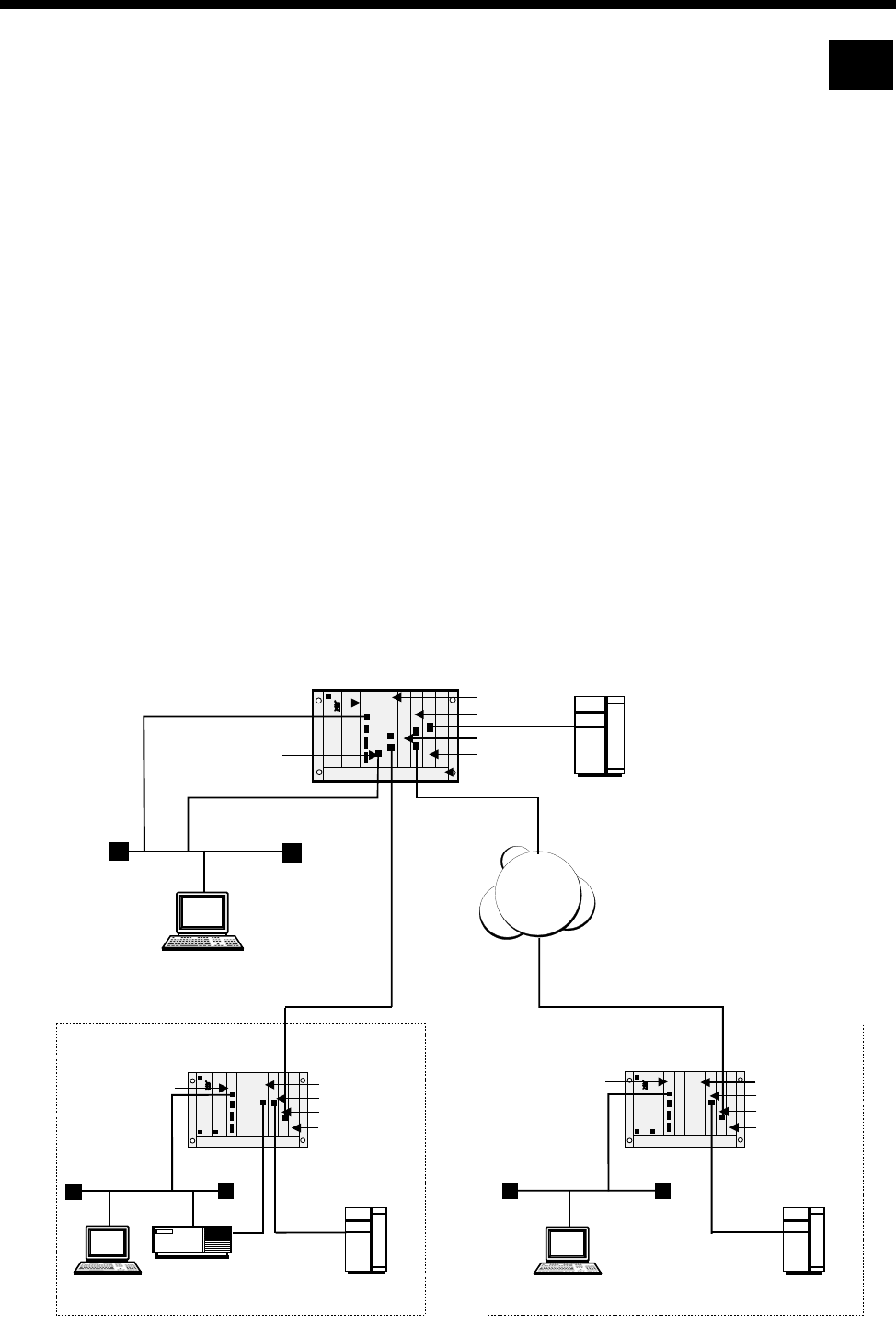
Applications 5-3
© 1993–2000 Jtec Pty Limited
TimeFrame Virtual Line applications
This section describes three typical TimeFrame Virtual Line applications. Example 1
shows a network of three nodes operating in a Wideband mode — one node acts as
the Central node and the other two as Branch Office nodes. Example 2 shows two
four slot chassis in a simple point-to-point network. Example 3 details the setting up
of a Multilink TimeFrame Network.
Example 1 - Three node Wideband network
In this setup, all three nodes are connected to a PABX via an EMM to provide a voice
service. Similarly each node is connected to a LAN to provide a data service. The
network routing is set up as follows:
•Central Site — the IRM acts as the Central Site Router and is manually connected
to Packet Port 2.
•Branch 1— uses an external router to perform routing and is connected to an X.21
port on the HSDM.
•Branch 2— uses the RM’s IP Router.
The connection between the Central Site and Branch 1 is via a DTM, while Branch 2
and the Central Site are connected via IPMTs and BCAM-ISOs.
RM
IRM
DTM
MFCM
IPMT
EMM
BCAM-ISO
Central Site
PABX
EMM
BCAM-ISO
Branch 2
RM
IPMT
LAN
PABX
MFCM
EMM
HSDM
Branch 1
RM
DTM
LAN
PABX
MFCM
Number range
1000-1999 Number range
2000-2999
Number range
3000-3999
(93640000-0099)
(93700000-0099)
(93900000-0099)
(192.195.50.100)
LAN
TimeFrame 248k TimeFrame 128k
(192.195.50.0)
(192.195.50.3)
(192.195.50.20)
(192.195.50.20)
(192.195.40.0)
(192.195.50.123)
Router
(192.195.30.100)
(192.195.30.21)
(192.195.70.0)
(192.195.30.0)
(192.195.30.123) (192.195.30.3)
(192.195.60.100)
(192.195.60.0)
(192.195.60.123)
(192.195.40.21)
ISDN
RM

5-4 TimeFrame Virtual Line applications
10003497.00 Rev.5
The following sections detail the configuration of each node using OmniVision.
General node configuration
The following table shows typical entries for management numbers, IP management
addresses and so on.
DTM configuration
The following table shows the settings for the DTM modules for Branch 1 and the
Central Site:
Lineset configuration
The following table shows the entries to set up Linesets:
Node OmV Management
No VX Number Range IP Management
Address Subnet Mask
Low High
Branch 1 93640098 93640000 93640099 192.195.30.100 255.255.255.0
Branch 2 93900098 93900000 93900099 192.195.60.100 255.255.255.0
Central Site 93700098 93700000 93700099 192.195.50.100 255.255.255.0
Node Port Trunk speed SubB-chann0el speed
Branch 1 1256k 56k
Central Site 1256k 56k
Node Number Range Members Comments
Low High
Branch
11000 1999 EMM Ports PABX extensions
2000 3999 TimeFrame Resources Remote PABX extensions
93700000 93700099 DTM Port 1 SubB &B Central Site
Branch
22000 2999 EMM Ports PABX extensions
1000
3000 1999
3999 TimeFrame Resources Remote PABX extensions
93900070 93900070 BCAM-ISO Ch 1&2
TimeFrame VLs Bearer from Central
Central
Site 3000 3999 EMM Ports PABX extensions
1000 2999 TimeFrame Resources Remote PABX extensions
93640000 93640099 DTM Port 1 SubB & B Branch Office 1
93700091 93700091 BCAM-ISO Ch 1&2
TimeFrame Resources Bearer to Branch 2

Applications 5-5
© 1993–2000 Jtec Pty Limited
Setting up Number Checking
The following table details the settings for Number Checking:
Configuring the BCAM-ISO
The following table shows the configuration for the BCAM-ISOs at Branch 2 and
Central Site.
Configuring the TimeFrame Virtual Line
The following tables show the TimeFrame VL settings. A TimeFrame VL is created
in the Virtual Lines Configuration.
Branch 1
Node No. to
check Number range Modification Apply to...
Low High
Branch 1 Called 2000 3999 Replace Called with
93700080 Lineset
2000-3999
Branch 2 Called 1000 1999 Replace Called with
93700091 Lineset
1000-1999
Called 3000 3999 Replace Called with
93700091 Lineset
3000-3999
Central Site Called 1000 1999 Replace Called with
93640091 Lineset
1000-2999
Called 2000 2999 Replace Called with
93900070 Lineset
1000-2999
Node Call Rate Mode Backplane
Branch 2 128 kbit/s 1 Switched
Central Site 128 kbit/s 1 Switched
Node Name TimeFrame
Trunk Name Line No. Max Port
speed Hotline
enable XSPC
enable Auto
Answer
Branch 1 B1Cent trunk1 93640091 256k No No Yes
Hotline
No. Inactivity
Timeout Outgoing
TE Min. Data
Bandwidth Don’t
Increment
Hotline No.
93700080 Disabled Any 32kbit/s Disabled

5-6 TimeFrame Virtual Line applications
10003497.00 Rev.5
Branch 2
Central Site
Note TimeFrame Virtual Line Lines are members of Linesets. No Line numbers are required.
Configuring the Timeframe Resources
The following table shows the number of TimeFrame Resources allocated at each site.
The TimeFrame Resources are configured in the Virtual Line configuration.
Configuring the Data
The external router at Branch 1 is connected to an X.21 port on an HSDM. It is
configured to encapsulate all IP data in Frame Relay over the X.21 connection. Frame
Relay encapsulation must be RFC1490 for the external router. The X.21 port is
configured to run at 248 kbit/s.
Refer to your Router documentation for configuration of the external router.
The network IP addresses of Branch 1, Central and Branch 2 are 192.195.30.0,
192.195.50.0 and 192.195.60.0 respectively. The WAN link between Central and
Branch 2 is assigned to be 192.195.40.0.
Node Name TimeFrame
Trunk Name Line No. Max Port
speed Hotline
enable XSPC
enable Auto
Answer
Branch 2 B2Cent trunk1 - 128k No No Yes
Hotline
No. Inactivity
Timeout Outgoing
TE Min. Data
Bandwidth Don’t
Increment
Hotline No.
93700091 Disabled Exclusive
BCAM-ISO 24kbit/s Enabled
Node Name TimeFrame
Trunk Name Line No. Max Port
speed Hotline
enable XSPC
enable Auto
Answer
Central
Site CentB1 trunk1 93700080 256k Yes Yes No
CentB2 trunk 2 - 128k Yes Yes No
Hotline
No. Inactivity
Timeout Outgoing
TE Min. Data
Bandwidth Don’t
Increment
Hotline No.
CentB1 trunk1 93640091 Disabled Any 32 kbit/s Disabled
CentB2 trunk 2 93900070 Disabled Exclusive
BCAM-ISO 24kbit/s Enabled
Node TimeFrame Resources
Branch 1 27
Branch 2 13
Central Site 40

Applications 5-7
© 1993–2000 Jtec Pty Limited
The network addresses for the WAN link between Central and Branch 1 should be
configured in accordance with the instructions in the external router user manual.
The diagram at the start of this section shows the IP address of each network device.
The external router at Branch 1 is configured to use DLCI=30, while the IRM at Central
uses DLCI= 30 and 31 for the connections to Branch 1 and Branch 2 respectively. The
IRM at Central is responsible for routing IP traffic originated from its LAN to Branch
1 and Branch 2. The data on the link between Branch 1 and Central is compressed,
whilst data between Branch 2 and Central is uncompressed.
The following sections discuss the configuration of each node in detail.
Branch 1
A virtual circuit of the external router is connected to one of the Packet Ports in the
HDLC Data Handler. A Packet Port can then be connected to any virtual circuit on
the TimeFrame Virtual Line via the Fast Packet Switch. In this example, the external
router’s virtual circuit (DLCI=30) is connected to Packet Port 1 (pktport1), which is
switched to trunk 1 by the Fast Packet Switch. The following diagram shows the
virtual circuit connection between the external router and a TimeFrame trunk.
The HDLC Data Handler must be configured to pass Frame Relay frames from the
router’s virtual circuit (DLCI=30) to the Fast Packet Switch without modification. This
can be achieved by setting the Packet Port’s virtual circuit data type to Frame Relay
(fr).
The data port to which the external router is connected must be manually connected
to Packet Port 1 before data can be passed to the HDLC Data Handler. Using
OmniVision select configuration for the port to which the external router is connected.
Once this is saved, create a manual connection between the data port and the line on
the RM called Packet Port 1.
Router
HDLC Data Handler
for packet port 1
Packet Channel
Handler for trunk 1
Fast Packet Switch
DLCI=30 DLCI=30
trunk 1
Virtual Circuit
5-8 TimeFrame Virtual Line applications
10003497.00 Rev.5
Use OmniVision’s Data Handling feature to configure the Virtual Circuit for Branch
1. The following table summarises the settings:
The next table shows the Frame Relay Route configuration settings
The Packet Port does not use the configured DLCI value if its data type is set to fr
(Frame Relay). This is because all fr frames originating from the external router are
forwarded by the Packet Port to the Packet Switch without encapsulation or
modification.
The DLCI values for the external router and trunk1 do not have to be identical. The
DLCI selected for trunk1 must be unique on the trunk and must not be used for any
other traffic than that originating from the external router. For example, the RM
internal router must not be configured to use a DLCI value of 30 on trunk1 in addition
to the external router.
Central site
Virtual circuits of the IRM at Central are assumed to be connected to pktport2. To
switch these virtual circuits to their corresponding destination (i.e. trunks), the Fast
Packet Switch must be set up to switch frames originating from pktport2 DLCI 30 to
trunk1 DLCI 30. Furthermore, frames sent from pktport2 DLCI 31 should be
switched to trunk2 DLCI 31. The following diagram illustrates the switching of these
virtual circuits.
The data port to which the IRM is connected must be manually connected to Packet
Port 2.
Virtual Circuit Interface DLCI Priority Data Type
High Medium Low
pktport1vc1 pktport1 don’t care fr ––
trunk1vc3 trunk1 30 all ––
Entry Port 1 ID Port 1
DLCI Port 2 ID Port 2
DLCI Data
Compression Data
Type
1 pktport1 30 trunk1 30 Yes all
IRM
HDLC Data Handler
for packet port 2
Packet Channel
Handler for trunk 1
Packet Channel
Handler for trunk 2
Fast Packet Switch
DLCI=30
DLCI=31
DLCI=31
DLCI=30
trunk 1
trunk 2
Virtual Circuit
OK
ALARM
CALL 1
CALL 2
CALL 3
CALL 4
ON
TEST
BUSY
ERROR
STAT
DATA
STAT
DATA
2
1
C
LMS
IRM

Applications 5-9
© 1993–2000 Jtec Pty Limited
Use OmniVision’s Data Handling feature to set up the Virtual Circuit and Frame
Relay Route. The following table summarises the Virtual Circuit settings:
The next table shows the Frame Relay Route configuration settings:
By default, the IRM enables user-side Frame Relay Permanent Virtual Circuit (PVC)
management procedures on an IRM Frame Relay port. The RM Packet port to which
the IRM port is connected (packet port 2) needs to perform network-side Frame Relay
PVC management procedures.
Since the IRM uses ANSI Frame Relay PVC management procedures, packet port 2
needs to be configured to T1.617a. The following table summarises the Frame Relay
PVC management parameters for packet port 2.
Virtual Circuit Interface DLCI Priority Data Type
High Medium Low
irm30 pktport2 30 fr ––
irm31 pktport2 31 fr ––
trunk1vc3 trunk1 30 all ––
trunk2vc3 trunk2 31 all ––
Entry Port 1 ID Port 1
DLCI Port 2 ID Port 2
DLCI Data
Compression Data
Type
1 pktport2 30 trunk1 30 Yes all
2 pktport2 31 trunk2 31 No all
Configuration parameter Value
Enable interface Yes
Enable PVC management procedures Yes
Protocol T1.617a
Mode Network
Error threshold 3
Monitored Events counter 4
Polling verification interval 15
Inactivity timeout 0
5-10 TimeFrame Virtual Line applications
10003497.00 Rev.5
Branch 2
Branch 2 uses the RM’s Internal Router for LAN/WAN routing. The virtual circuit
connection between the Internal Router and a TimeFrame trunk is shown in the
following diagram. Branch 2 is configured to use internal router WAN port 1 to route
IP data to Central.
The RM’s Internal IP Router has been pre-configured to use DLCI 51 to DLCI 58,
which corresponds to WAN port 1 to 8 respectively. Traffic from a WAN port is
subsequently switched to a virtual circuit on the appropriate trunk via the Fast Packet
Switch. As a convention, WAN port x is switched to trunk x. For example, WAN port
1 should be switched to trunk 1.
Use OmniVision’s Data Handling feature to configure the Virtual Circuit for Branch
2. The following table summarises the settings:
The next table shows the Frame Relay Route configuration settings:
Virtual Circuit Interface DLCI Priority Data Type
High Medium Low
routervc1 router 51 all ––
trunk1vc3 trunk1 31 all ––
Entry Port 1 ID Port 1
DLCI Port 2 ID Port 2
DLCI Data
Compression Data
Type
1 router 51 trunk1 31 No all
Router WAN port 1 Packet Channel
Handler for trunk 1
Fast Packet Switch
DLCI=51 DLCI=31
trunk 1
Virtual Circuit

Applications 5-11
© 1993–2000 Jtec Pty Limited
Configuration summary
The following tables summarise the configuration details of Branch 1, Branch 2 and
the Central site.
Branch 1
RM LAN configuration
Virtual circuit configuration
Frame Relay route configuration
HSDM port 1 settings
Packet port 1 settings
Manual connections
Port Local IP address Local subnet mask ARP RIP Metric MTU
LAN 192.195.30.100 255.255.255.0 Y Y 1 1500
Virtual circuit Interface DLCI High priority Data
type Med priority
Data type Low priority
Data type
pktport1vc1 pktport1 don’t care fr ——
trunk1vc3 trunk1 30 all ——
Entry Port1 ID Port1 DCLI Port2 ID Port2 DCLI Data comp. Data type
1 pktport1 30 trunk1 30 Y all
Port Name Speed
HSDM port 1 248kbit/s
Port Name Speed Parameter Value
Packet port 1 248kbit/s Enable interface Yes
Enable PVC management procedures No
Inactivity timeout 0
From To
HSDM port 1:1 Packet Port 1:1
HSDM port 1:2 Packet Port 1:2
HSDM port 1:3 Packet Port 1:3
HSDM port 1:4 Packet Port 1:4

5-12 TimeFrame Virtual Line applications
10003497.00 Rev.5
Branch 2
RM LAN/WAN configuration
Virtual circuit configuration
Frame Relay route configuration
Central
RM LAN configuration
Packet port 2 settings
Port Local IP
address Local subnet
mask ARP RIP Metric MTU Un-
numbered
link
Remote
IP add Remote
subnet
mask
LAN 192.195.60.100 255.255.255.0 Y Y 1 1500 ———
WAN1 192.195.40.21 255.255.255.0 Y Y 1 1522 Nn ——
Virtual circuit Interface DLCI High priority Data
type Med priority
Data type Low priority
Data type
routervc1 router 51 all ——
trunk1vc3 trunk1 31 all ——
Entry Port1 ID Port1 DCLI Port2 ID Port2 DCLI Data comp. Data type
1 router 51 trunk1 31 N all
Port Local IP address Local subnet mask ARP RIP Metric MTU
LAN 192.195.50.100 255.255.255.0 Y Y 1 1500
Port Name Speed Line Fill Parameter Value
Packet port 2 384kbit/s Flag Enable interface Yes
Enable PVC management procedures No
Protocol T1.617a
Mode Network
Error Threshold 3
Monitored events counter 4
Polling verification interval 15
Inactivity timeout 0

Applications 5-13
© 1993–2000 Jtec Pty Limited
Virtual circuit configuration
Frame Relay route configuration
IRM configuration
Manual connections
Virtual circuit Interface DLCI High priority Data
type Med priority
Data type Low priority
Data type
irm30 pktport2 30 fr ——
irm31 pktport2 31 fr
trunk1vc3 trunk1 30 all ——
trunk2vc3 trunk2 31 all ——
Entry Port1 ID Port1 DCLI Port2 ID Port2 DCLI Data comp. Data type
1 pktport2 30 trunk1 30 Y all
2 pktport2 31 trunk2 31 N all
Port name Speed
WAN A Port (0) 384kbit/s
Logical port Physical port IP Address IP Address
mask IP Port
routing RIP Management
type Channel
1 1 192.195.50.3 255.255.255.0 Enabled Enabled ––
13 3 192.195.70.20 255.255.255.0 Enabled Enabled ansiT1-617-D 30
14 3 192.195.40.20 255.255.255.0 Enabled Enabled ansiT1-617-D 31
From To
IRM WAN A-1 line 0 Packet port 2:1
IRM WAN A-1 line 1 Packet port 2:2
IRM WAN A-1 line 2 Packet port 2:3
IRM WAN A-1 line 3 Packet port 2:4
IRM WAN A-1 line 4 Packet port 2:5
IRM WAN A-1 line 5 Packet port 2:6
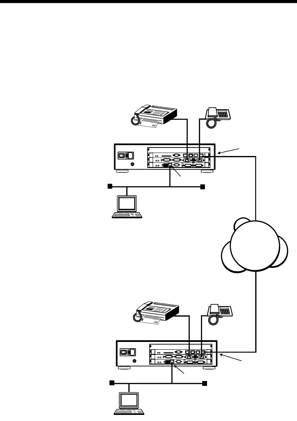
5-14 TimeFrame Virtual Line applications
10003497.00 Rev.5
Example 2 — Point-to-point network
This network shows a simple point-to-point network using two four slot chassis
connected to a Basic Rate ISDN service. Each node uses the internal IP router within
the Resource Manager and has a telephone and a Fax connected to the ALIM-EXCH
ports on a COMBO module.
ISDN
X.21
X.21
4
QBRM
X.21
X.21
4
QBRM
City A
City B
(9390 0000 - 9390 0009)
Fax No. 2001
Fax No. 1001
Tel No. 2000
Tel No. 1000
Connected to Combo ALIM-EXCH ports
Connected to Combo ALIM-EXCH ports
Connected to QBRM port
Connected to QBRM port
(LAN) 192.168.10.0
(RM) 192.168.10.100
(PC) 192.168.10.101
(LAN) 192.168.20.0
(PC) 192.168.20.101
(RM) 192.168.20.100
(9364 000 - 9364 0009)

Applications 5-15
© 1993–2000 Jtec Pty Limited
The City A site uses XSPCs to establish the connection to City B. The following section
details the configuration of each node using OmniVision and the RM Telnet Server.
Node configuration
Lineset configuration
Number checking
TimeFrame Virtual Line
Node Omv Manager
Number VX Number Range IP Management
Address Subnet Mask
Low High
City A 9390 0009 9390 0000 9390 0009 192.168.10.100 255.255.255.0
City B 9364 0009 9364 0000 9364 0009 192.168.20.100 255.255.255.0
Node Number Range Members Comments
Low High
City A 2000 2000 ALIM Port 1 Phone extension
2001 2001 ALIM Port 2 Fax extension
1000 1001 TimeFrame resources Remote extensions
9390 0001 9390 0001 TimeFrame Virtual Line Bearer from City B
City B 1000 1000 ALIM Port 1 Phone extension
1001 1001 ALIM Port 2 Fax extension
2000 2001 TimeFrame resources Remote extensions
9364 0001 9364 0001 TimeFrame Virtual Line Bearer from City A
Node Number to
check Number Range Modification Apply to...
Low High
City A Called 1000 1001 Replace called with 9364 0001 Lineset 1000-1001
City B Called 2000 2001 Replace called with 9390 0001 Lineset 2000-2001
Node Name TimeFrame
trunk name Hotline
No. Max
Port
Speed
Hotline
enable XSPC
enable Auto
Answer Minimum
Data
Bandwidth
Inactivity
Timer
City A City B trunk1 9364 0001 64 kbit/s Yes Yes No 48 kbit/s Disabled
City B City A trunk1 9390 0001 64 kbit/s No No Yes 48 kbit/s Disabled

5-16 TimeFrame Virtual Line applications
10003497.00 Rev.5
TimeFrame Resources
Configuring Data
The default settings for this scenario are sufficient to enable the LAN data connection
to be established. The defaults are as follows:
•IP Routing
•Unnumbered link
•RIP: Enabled
•DLCI: 100 on trunk1 at both ends.
The only configuration that needs to be entered is the FR route configuration as shown
below. You can also, optionally, enable or disable compression.
To alter these settings use the Data Handler feature in OmniVision.
Configuration summary
City A
LAN/WAN configuration
Virtual Circuit configuration
FR route configuration
Node TimeFrame Resources
City A 2
City B 2
Port Local IP
Address Local Subnet
Mask ARP RIP Metric MTU Un-
numbered
line
Remote
IP Addr. Remote
Subnet Mask
LAN 192.168.10.100 255.255.255.0 Yes Yes 1 1500 —— —
WAN1 0.0.0.0 255.255.255.0 Yes Yes 1 1500 Yes 0.0.0.0 255.255.255.0
Virtual Circuit Interface DLCI High priority
data type Medium priority
data type Low priority
data type
routervc1 router 51 ip ——
trunk1vc1 trunk1 100 all ——
Entry Port 1 ID Port 1
DLCI Port 2 ID Port 2 DLCI Data
compression Data type
1 router 51 trunk1 100 No ip

Applications 5-17
© 1993–2000 Jtec Pty Limited
City B
LAN/WAN configuration
Virtual Circuit configuration
FR route configuration
Port Local IP
Address Local Subnet
Mask ARP RIP Metric MTU Un-
numbered
line
Remote
IP Addr. Remote
Subnet Mask
LAN 192.168.20.100 255.255.255.0 Yes Yes 1 1500 —— —
WAN1 0.0.0.0 255.255.255.0 Yes Yes 1 1500 Yes 0.0.0.0 255.255.255.0
Virtual Circuit Interface DLCI High priority
data type Medium priority
data type Low priority
data type
routervc1 router 51 ip ——
trunk1vc1 trunk1 100 all ——
Entry Port 1 ID Port 1
DLCI Port 2 ID Port 2 DLCI Data
compression Data type
1 router 51 trunk1 100 No ip
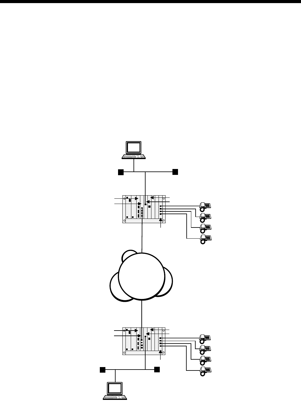
5-18 TimeFrame Virtual Line applications
10003497.00 Rev.5
Example 3 — Multilink TimeFrame Network
If your Router supports Multilink, you can use TimeFrame Virtual Lines in the
Multilink network.
The following example shows a typical point-to-point network over ISDN. Here, a
Frame Switch Module (FSM) is used to Multilink two TimeFrame Virtual Lines to
provide an IP Network across a WAN bandwidth of 128 kbit/s. Voice services are
provided by telephones connected to ALEM-2 modules.
The IP Router in the RM is not used in this example, as it does not support Multilink.
In this case, the FSM Router is used, and connects to TimeFrame via two 64 kbit/s
Packet Ports. The following diagram shows the network.
City B
City A
QBRM
RM
ALEM-2
LAN
MFCM
FSM
Handset 1
Handset 2
Handset
3
Handset
4
QBRM
RM
ALEM-2
LAN
MFCM
FSM
Handset 1
Handset 2
Handset 3
Handset 4
ISDN

Applications 5-19
© 1993–2000 Jtec Pty Limited
Optimising data throughput
To achieve the most efficient data throughput, the voice calls in this network are
distributed evenly across both trunks. This is necessary because of the way in which
the Multilink algorithm operates in most routers. Generally, the router expects the
trunks, over which it is forming a Multilink bundle, to be at the same data rate – this
is when Multilink is most efficient.
When there is a large difference in trunk bandwidth, Multilink is not as efficient
because it wastes the excess bandwidth. For example, if a Multilink has two trunks
at 64 kbit/s and 32 kbit/s respectively, the effective bandwidth is 64 kbit/s. This
bandwidth is formed from 32 kbit/s from the first trunk (with 32 kbit/s excess
wasted) and 32 kbit/s of the second trunk. If this was split into two trunks of 48 kbit/s,
the effective bandwidth is 96 kbit/s, because Multilink would fully utilise both trunks
and no bandwidth is lost.
The example below describes how you can configure the J5000 to provide Multilink
with two equal data rate trunks. This is achieved by alternating the compressed voice
circuits onto two different TimeFrame Virtual Lines. The configuration involves using
a combination of Interwork Units (IWUs) and CLI/Number Checking to direct
odd-numbered calls down TimeFrame VL 1, and even-numbered calls down
TimeFrame VL 2.
VX Configuration
TimeFrame Virtual Line Configuration
Note There are four TimeFrame Resources enabled in TimeFrame Capacity on each
node.
Node Omv Manager Number VX Number Range
Low High
City A 9390 0009 9390 0000 9390 0009
City B 9364 0009 9364 0000 9364 0009
Node Name Trunk
name Line No. Hotline
No. Hotline
enable XSPC
enable Auto
Answer Port
Speed Inactivity
Timeout
City A CityB_1
CityB_2
trunk1
trunk2
93900001
93900002
93640001
93640002
Yes
Yes
No
No
No
No
64 kbit/s
64 kbit/s
30 secs
30 secs
City B CityA_1
CityA_2
trunk1
trunk2
93640001
93640002
93900001
93900002
Yes
Yes
No
No
No
No
64 kbit/s
64 kbit/s
30 secs
30 secs

5-20 TimeFrame Virtual Line applications
10003497.00 Rev.5
Interwork Configuration
Lineset configuration
CLI/Number Checking
Configuration
Node Number of
Interworks Configuration
City A 1 Default configuration used for each IWU
City B 1 Default configuration used for each IWU
Node Number Range Members Comments
Low High
City A 1000
2000
3000
4000
1003
2003
3000
4000
1-1L, 1-2L, 1-3L, 1-4L
ALEM-2 Ports 1,2,3,4
TimeFrame Resources
TimeFrame Resources
Four Left Hand Interwork Units
Four ALEM-2 Ports
All four TimeFrame Resources (trunk1)
All four TimeFrame Resources (trunk2)
City B 1000
2000
3000
4000
1003
2003
3000
4000
ALEM-2 Ports 1,2,3,4
1-1L, 1-2L, 1-3L, 1-4L
TimeFrame Resources
TimeFrame Resources
Four ALEM-2 Ports
Four Left Hand Interwork Units
All four TimeFrame Resources (trunk1)
All four TimeFrame Resources (trunk2)
Node List Name Number to Check Apply when line is... Modification
City A citybtf1
citybtf2
prefix1
prefix2
strip
Called Party No.
Called Party No.
Called Party No.
Called Party No.
Called Party No.
Call Destination
Call Destination
Call Source
Call Source
Call Source
Replace Called Party No. with 93640001
Replace Called Party No. with 93640002
Prefix Called Party No. with 3000
Prefix Called Party No. with 4000
Remove first 4 digits of Called Party No.
City B cityatf1
cityatf2
prefix1
prefix2
strip
Called Party No.
Called Party No.
Called Party No.
Called Party No.
Called Party No.
Call Destination
Call Destination
Call Source
Call Source
Call Source
Replace Called Party No. with 93900001
Replace Called Party No. with 93900002
Prefix Called Party No. with 3000
Prefix Called Party No. with 4000
Remove first 4 digits of Called Party No.

Applications 5-21
© 1993–2000 Jtec Pty Limited
Apply to...
Packet Ports
FSM Configuration
Note For Multilink to take effect, the FSMs must be reset after making these configuration
changes.
Node List
Name Apply to... Number Range Comments
Low High
City A citybtf1
citybtf2
prefix1
prefix2
strip
All TF Resources
All TF Resources
1-1R, 1-3 R
1-2R, 1-4R
All TF Resources
3000
4000
1000
1000
3000
3000
4000
1003
1003
4000
Switches all calls starting with 3000 onto trunk1
Switches all calls starting with 4000 onto trunk2
Applied to all odd-numbered RH IWU involved in call
Applied to all even-numbered RH IWU involved in call
Strip 3000 and 4000 prefixes from received calls
City B cityatf1
cityatf2
prefix1
prefix2
strip
All TF Resources
All TF Resources
1-1R, 1-3 R
1-2R, 1-4R
All TF Resources
3000
4000
2000
2000
3000
3000
4000
2003
2003
4000
Switches all calls starting with 3000 onto trunk1
Switches all calls starting with 4000 onto trunk2
Applied to all odd-numbered RH IWU involved in call
Applied to all even-numbered RH IWU involved in call
Strip 3000 and 4000 prefixes from received calls
Node Packet Port
Number Speed Comment
City A Packet Port 1
Packet Port 2
64kbit/s
64kbit/s
All other configuration is default
All other configuration is default
City B Packet Port 1
Packet Port 2
64kbit/s
64kbit/s
All other configuration is default
All other configuration is default
Node Port Address Routing Configuration
City A 192.195.30.100 Default Route to PPP Port 1
City B 192.195.50.100 Default Route to PPP Port 1
Node WAN
Port No. IP Address Authentication PPP Settings
City A 1
2
192.195.40.1
192.195.40.101
None
None
Numbered Link to 192.195.40.2 / MP Start of Bundle
Numbered Link to 192.195.40.102 / MP Bundle Member
City B 1
2
192.195.40.2
192.195.40.102
None
None
Numbered Link to 192.195.40.1 / MP Start of Bundle
Numbered Link to 192.195.40.101 / MP Bundle Member

5-22 TimeFrame Virtual Line applications
10003497.00 Rev.5
Manual Connections
Virtual Circuit Configuration
Frame Relay Route Configuration
Voice operation
First call
The following steps summarise how the first voice call from City A reaches an
ALEM-2 port in City B. Refer to the diagram on page 5-18.
1 City A ALEM-2 receives 1000 from handset.
2 Call Handling matches this to LHS Interwork Unit 1.
3 Number Checking prefixes 1000 with 3000 to give a number 30001000.
4 Call Handling in City A matches this onto a TimeFrame Resource on trunk 1.
5 Call Handling in City B receives the call to 30001000 from City A.
6 Number Checking strips the first 4 digits from the number, leaving 1000.
Node Manual Connections
City A FSM Line 1 to Packet Port 1
FSM Line 2 to Packet Port 2
City B FSM Line 1 to Packet Port 1
FSM Line 2 to Packet Port 2
Node Interface Name DLCI High
Priority
Data
Med.
Priority
Data
Low
Priority
Data
City A Packet Port 1 pktport1vc1 100 7e ——
City A Packet Port 2 pktport2vc2 100 7e ——
City B Packet Port 1 pktport1vc1 100 7e ——
City B Packet Port 2 pktport2vc2 100 7e ——
Node Entry Port 1
ID Port 1
DLCI Port 2
ID Port 2
DLCI Data
Compression Data
Type
City A 1
2
pktport1
pktport2
100
100
trunk1
trunk2
100
100
No
No
all
all
City B 1
2
pktport1
pktport2
100
100
trunk1
trunk2
100
100
No
No
all
all

Applications 5-23
© 1993–2000 Jtec Pty Limited
7 Call Handling in City B matches this onto the first available ALEM-2 port.
8 ALEM-2 port rings the attached handset.
Second call
The following steps summarise how the second voice call from City A reaches an
ALEM-2 port in City B. Refer to the diagram on page 5-18.
1 City A ALEM-2 receives 1001 from handset.
2 Call Handling matches this to LHS Interwork Unit 2.
3 Number Checking prefixes 1001 with 4000 to give a number 40001001.
4 Call Handling in City A matches this onto a TimeFrame Resource on trunk 2.
5 Call Handling in City B receives the call to 40001001 from City A.
6 Number Checking strips the first 4 digits from the number, leaving 1001.
7 Call Handling in City B matches this onto the next available ALEM-2 port.
8 ALEM-2 port rings the attached handset.
When these two calls have been made, both TimeFrame Virtual Line 1 and TimeFrame
Virtual Line 2 have a data bandwidth of 56 Kbit/s, which is maximising the data
throughput for PPP.
5-24 Subrate Virtual Line applications
10003497.00 Rev.5
Subrate Virtual Line applications
This section provides examples of the settings required for Access Controller (AC)
and Virtual eXchange (VX) equipment to enable Virtual Line (VL) operation.
Setting up VLs in an Access Controller
When adding the various line types to a Virtual Line in a J1000 AC, use the following
settings for the Call Establishment Modes of the Virtual Line and the relevant module.
Virtual Line Type Virtual Line Setting Module setting
ALEM/ALPM etc. DLMs and B-SAM
SPC/Manual
Connection
operation
SPC
Label required for real
SPCs
SPC
E2E
National Significant
Remote Number
SPC
XSPC operation SPC
E2E
Hotline (both ends)
XSPC (one end only)
CM-SAM is optional
SPC
E2E
SPC
On Demand
operation SPC
E2E
Hotline (both ends)
CM-SAM is optional
SPC
E2E
SPC
RM CM
Applications 5-25
© 1993–2000 Jtec Pty Limited
Setting up Interworking Units as members of a Virtual Line on a VX
Use the following settings for the Call Establishment Modes of the VL and IWU when
configuring a Subrate Virtual Line in a J1000/J5000 Virtual eXchange. Note that when
connecting a VL to another Virtual eXchange, the settings are different to those
required for connection to a J1000 Access Controller.
1 The SPC is set so that it does not drop the call when the last member of the Virtual
Line clears.
Note We recommend that you use XSPC operation instead of manual connections for the
configurations shown above.
Virtual Line
Type Virtual Line Setting IWU-R connected to a
remote VX IWU-R connected to a
remote AC
SPC/Manual
connection
operation
SPC
Label required for
real SPCs
No Label for Manual
connection
SPC and own label
E2E
National Significant
Remote Number
E2E Service Tones
Transparent
SPC and label
E2E
National Significant
Remote Number
E2E Service Tones
Transparent
XSPC
operation SPC
E2E
Hotline (both ends)
XSPC (one end only)
CM-SAM is optional
SPC1
E2E
E2E Service Tones
Transparent
SPC
E2E
E2E Service Tones
Transparent
On Demand
operation SPC
E2E
Hotline (both ends)
CM-SAM is optional
SPC
E2E
E2E Service Tones
Transparent
SPC
E2E
E2E Service Tones
Transparent
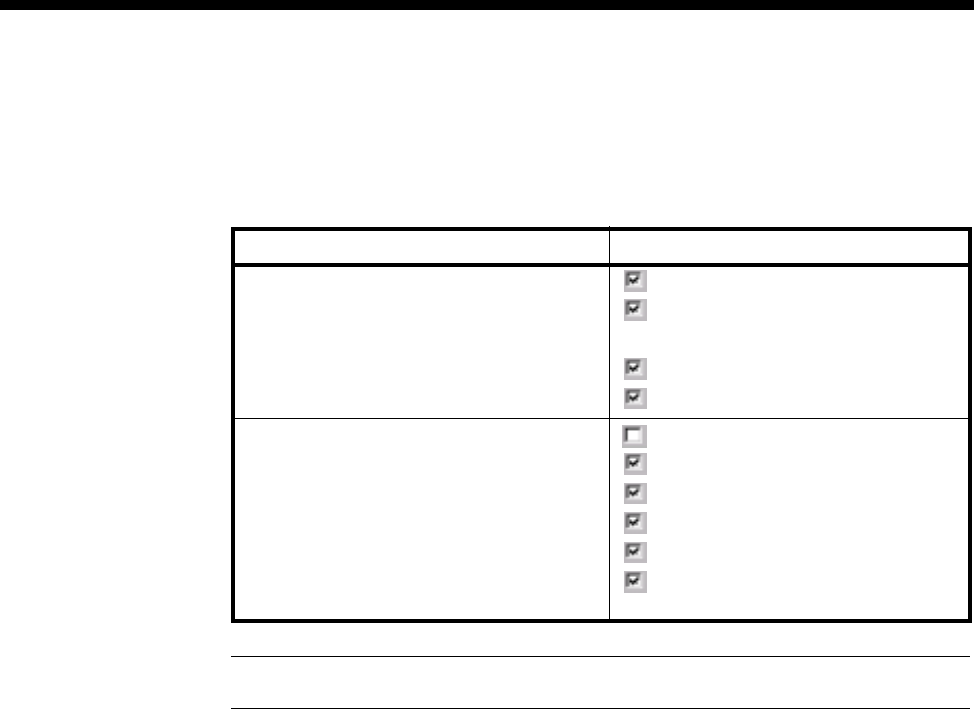
5-26 Subrate Virtual Line applications
10003497.00 Rev.5
Setting up a 64K call using Interworking Units
To set up a 64K call via an IWU, use the following Call Establishment Mode settings
for the IWU:
Note Transparent should be disabled if the remote end is not an Interworking channel.
Virtual Line Type IWU-R settings
SPC/Manual connection operation SPC and own label
E2E
National Significant Remote Number
E2E Service Tones
Transparent (see Note)
XSPC operation SPC
E2E
E2E Service Tones
Transparent (see Note)
Hotline
XSPC (at one end only, Auto Answer
enabled at the other end)
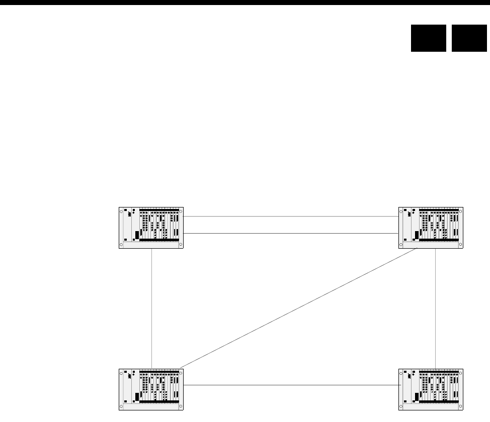
Applications 5-27
© 1993–2000 Jtec Pty Limited
MicropleX switching applications
MicropleX switching allows switching onto Subrate or TimeFrame Virtual Lines to
be performed within a single VX. A new type of subchannel line is configured which
is not connected to any physical port. This line can be configured to be Subrate voice
or Subrate data. In the case of voice, an LDCM, MFCM or COMBO compander is used
to connect the port. For data, an SRMM Subrate switch is used. This new line can
have calls directed to it, using the normal call routing techniques such as matching
line numbers and/or linesets. The following diagram shows a typical network on
which to apply this form of switching.
The sample network connects sites in Brisbane, Sydney, Canberra and Melbourne.
Two tie lines are provided between Sydney and Brisbane since most call traffic will
flow between these two sites. Redundancy is provided by the tie lines between
Sydney and Canberra and between Melbourne and Brisbane. The tie lines are
established using XSPCs. Channel signalling is also used. See page 3-38 for general
instructions on configuration of D- and B- channel signalling, SPC/XSPC/manual
connection or demand-established operation.
The convention of having left Interwork Unit lines as members of linesets and right
Interworking Unit lines as Virtual Line members is followed for this configuration.
The ’R’ in the above network connection diagram indicates that the Interworking Unit
lines which are members of the lineset have their order reversed to minimise call
collisions. See ISDN Interworking on page 3-26 for more information.
BRI -SYD1
BRI -SYD2
Brisbane Sydney
Canberra
CAN - SYD1
CAN - MEL1
BRI - MEL1
Melbourne
R
R
R
R
R
R
MEL - SYD1
RM CM

5-28 MicropleX switching applications
10003497.00 Rev.5
The table below lists the routes and the Interworking Unit lines which are members
of the Virtual Line for each route. Interworking Unit A indicates the Interworking
Unit lines which are members of the lineset defining the route in Node A and
Interworking Unit B for Node B.
The following table lists the lineset number ranges and line members defined in each
node. The routes associated with the number ranges are also listed. The ordering of
the routes in the table indicates the priority for each route. For example, a call from
Sydney to Melbourne will choose the MEL-SYD1 route first, followed by the
CAN-SYD1 route (Sydney - Canberra - Melbourne), and the last choices are the
BRI-SYD1 and BRI-SYD2 routes (Sydney - Brisbane - Melbourne).
Route Node A Interworking
Unit A Node B Interworking
Unit B
BRI-SYD1 Brisbane 2/(1-4)R Sydney 3/(1-4)R
BRI-SYD2 Brisbane 2/(5-8)R Sydney 3/(5-8)R
BRI-MEL1 Brisbane 1/(1-4)R Melbourne 3/(1-4)R
CAN-MEL1 Canberra 1/(1-4)R Melbourne 2/(1-4)R
MEL-SYD1 Melbourne 1/(1-4)R Sydney 1/(1-4)R
CAN-SYD1 Canberra 2/(1-4)R Sydney 2/(1-4)R
Node Lineset range Member Interworking
Unit lines Associated route
Sydney 03 - 03 1/(4-1)L (Reversed) MEL-SYD1
2/(4-1)L (Reversed) CAN-SYD1
3/(4-1)L (Reversed) BRI-SYD1
3/(8-5)L (Reversed) BRI-SYD2
026 - 026 2/(4-1)L (Reversed) CAN-SYD1
1/(4-1)L (Reversed) MEL-SYD1
3/(4-1)L (Reversed) BRI-SYD1
3/(8-5)L (Reversed) BRI-SYD2
07 - 07 3/(4-1)L (Reversed) BRI-SYD1
3/(8-5)L (Reversed) BRI-SYD2
1/(4-1)L (Reversed) MEL-SYD1
2/(4-1)L (Reversed) CAN-SYD1

Applications 5-29
© 1993–2000 Jtec Pty Limited
The VX number range is defined as the range of the PRA or BRA number range. The
area code is set to the city area code without the leading 0. For this application a VX
call capacity of 15 calls should be adequate.
Melbourne 07 - 07 3/(4-1)L (Reversed) BRI-MEL1
1/(4-1)L (Reversed) MEL-SYD1
2/(4-1)L (Reversed) CAN-MEL1
026 - 026 2/(4-1)L (Reversed) CAN-MEL1
1/(4-1)L (Reversed) MEL-SYD1
3/(4-1)L (Reversed) BRI-MEL1
029 - 029 1/(1-4)L MEL-SYD1
2/(1-4)L CAN-MEL1
3/(1-4)L BRI-MEL1
Canberra 029 - 029 2/(1-4)L CAN-SYD1
1/(1-4)L CAN-MEL1
03 - 03 1/(1-4)L CAN-MEL1
2/(1-4)L CAN-SYD1
07 - 07 2/(1-4)L CAN-SYD1
1/(1-4)L CAN-MEL1
Brisbane 026 - 026 2/(1-4)L BRI-SYD1
2/(5-8)L BRI-SYD2
1/(1-4)L BRI-MEL1
03 - 03 1/(1-4)L BRI-MEL1
2/(1-4)L BRI-SYD1
2/(5-8)L BRI-SYD2
029 - 029 2/(1-4)L BRI-SYD1
2/(5-8)L BRI-SYD2
1/(1-4)L BRI-MEL1
Node Lineset range Member Interworking
Unit lines Associated route
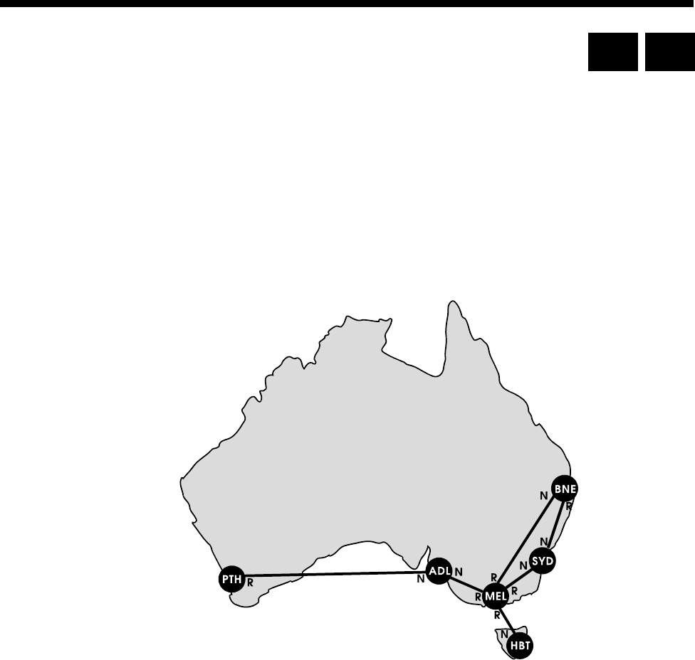
5-30 Virtual eXchange applications
10003497.00 Rev.5
Virtual eXchange applications
Introduction
The example network described in this section illustrates a private network
connecting Australia’s major cities. Each node in the network is a Virtual eXchange.
The links between the nodes are 2.048 Mbit/s lease lines (for example, Telstra
Megalink). Both ends of each leased line are terminated at IPMNs, such that the
private network path between two VXs is implemented as an 'IPMN to leased line to
IPMN’ connection. The network shown below also provides redundant paths for the
Sydney, Melbourne and Brisbane nodes.
The following sections describe the configuration of the network shown above. All
configuration parameters are mandatory unless indicated as optional.
VX configuration
For full details on configuring the VX see page 3-15 of the System configuration section.
To configure the VX for the example network carry out the following steps:
1 Enable the VX by checking the Enable VX checkbox in the VX Configuration
dialog.
2 Set the VX call Capacity to an appropriate number of calls, for example 45.
3 Set the VX Tones or leave them at their default settings (optional).
4 Enter the Minimum number in this device, the Maximum number in this device,
and the Area code for each node.
RM CM

Applications 5-31
© 1993–2000 Jtec Pty Limited
5 Configure Call charging (optional)
6 Set Endless loop prevention to 4. This is the longest path within this example
network.
RM/CM configuration
For a fuller explanation of RM and CM configuration, see page 3-5 and page 3-3
respectively, in the System configuration section.
1 Enter the Manager Access number.
2 Enable Resubmit calls from TE.
3 Enable Resubmit calls from NT.
4 Enable Log resubmitted calls (optional).
Route configuration
The following table shows the configuration for the routes at each node. The numbers
programmed into the linesets represent the area codes of the destinations serviced by
the node. The IPMN line order for each route corresponds to the Normal (N) or
Reversed (R) order indicated on the example network.
The linesets defined below provide for least-cost routing to NSW and VIC country
areas, and Canberra/ACT by routing the call to the nearest capital city node. For
example, if the Melbourne node receives a call for Canberra (area code 062), it will
attempt to send it to the Sydney node via the Sydney private trunk (SYD). The Sydney
node, upon receiving a call for Canberra, will fail to match the 062 number to a lineset
or locally assigned line. Consequently, it will send the call to a TE module (IPMT),
from which point the public ISDN will route the call.
For simplicity, this example assumes that charges incurred for public ISDN switching
of calls to any destination within a State’s boundaries are least expensive if the call is
made from the capital city of that State, and not a neighbouring one. This may not
necessarily be the case, as public ISDN call charging is usually based on the radial
distance of the destination from the source. To fine tune the least-cost routing
characteristics, different linesets with narrower number ranges would need to be
configured.
The IPMNs have been assigned to the linesets in order of shortest path first. For
example, the Melbourne destination linesets in the Sydney node have been
configured with the direct route to Melbourne as the first member, and the indirect
Brisbane route as the second member. This configuration provides the following call
path preference:
•1st Sydney—Melbourne
•2nd Sydney—Brisbane—Melbourne.
Each lineset has Allow TE submission when call not originating from this device
fails enabled and Allow calls arriving on member interface to be sent back on same
interface disabled.

5-32 Virtual eXchange applications
10003497.00 Rev.5
Configuration details table
VX Node Destination Linesets
(min-max) Member routes
(Private line
IPMNs)
IPMN line
order
Sydney
Area codes
serviced by this
node begin with
02, 04 and 06.
Hobart & TAS 002—002 MEL (Melbourne)
BNE (Brisbane) Normal
Normal
Melbourne 03—03 MEL (Melbourne)
BNE (Brisbane) Normal
Normal
VIC 05—05 MEL (Melbourne)
BNE (Brisbane) Normal
Normal
Brisbane & QLD 07—07 BNE (Brisbane)
MEL (Melbourne) Normal
Normal
Adelaide & SA
Perth & WA 08—09 MEL(Melbourne)
BNE (Brisbane) Normal
Normal
Melbourne
Area codes
serviced by this
node begin with
03 and 05
Hobart & TAS 002—002 HBT (Hobart Reversed
Sydney 02—02 SYD (Sydney)
BNE (Brisbane) Reversed
Reversed
NSW 04—04 SYD (Sydney)
BNE (Brisbane Reversed
Reversed
Canberra & ACT 06—06 SYD (Sydney)
BNE (Brisbane Reversed
Reversed
Brisbane & QLD 07—07 BNE (Brisbane)
SYD (Sydney) Reversed
Reversed
Adelaide & SA
Pert & WA 08—09 ADL (Adelaide) Reversed
Adelaide
Area codes
serviced by this
node begin with
08
Hobart & TAS 002—002 MEL (Melbourne) Normal
Sydney
Melbourne
NSW
VIC
Canberra & ACT
Brisbane & QLD
02—07 MEL (Melbourne) Normal
Perth & WA 09—09 PTH (Perth) Normal
Brisbane
Area codes
serviced by this
node begin with
07
Hobart & TAS 002—002 MEL (Melbourne)
SYD (Sydney) Normal
Reversed
Sydney 02—02 SYD (Sydney)
MEL (Melbourne) Reversed
Normal
Melbourne 03—03 MEL (Melbourne)
SYD (Sydney) Normal
Reversed
NSW 04—04 SYD (Sydney)
MEL (Melbourne) Reversed
Normal
VIC 05—05 MEL (Melbourne)
SYD (Sydney) Normal
Reversed
Canberra & ACT 06—06 SYD (Sydney)
MEL (Melbourne) Reversed
Normal
Adelaide & SA
Perth & WA 08—09 MEL (Melbourne)
SYD (Sydney) Normal
Reversed

Applications 5-33
© 1993–2000 Jtec Pty Limited
Perth
Area codes
serviced by this
node begin with
09
Hobart & TAS 002—002 ADL (Adelaide) Reversed
Sydney
Melbourne
NSW
VIC
Canberra & ACT
Brisbane & QLD
Adelaide & SA
02—08 ADL (Adelaide) Reversed
Hobart
Area codes
serviced by this
node begin with
002
Sydney
Melbourne
NSW
VIC
Canberra & ACT
Brisbane & QLD
Adelaide & SA
02—08 MEL (Melbourne) Normal
VX Node Destination Linesets
(min-max) Member routes
(Private line
IPMNs)
IPMN line
order
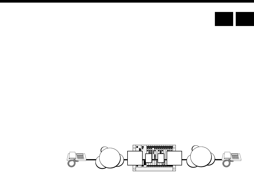
5-34 Interworking applications
10003497.00 Rev.5
Interworking applications
This section details several scenarios for operating with the Interworking feature of
this equipment. For further information on configuring Interworking see page 3-26
in the System configuration section.
In the following examples only the non-default settings are detailed. All other settings
are assumed to be at their default value. Where any examples show the use of an
IPMT, you may also use a BRMT. Similarly, where an Access Controller is specified,
you may also use a VX.
Switched calls between two networks
In this application example, the called number or range of numbers are on a different
network to the one originating the call.
Configuration
1 Install one Interwork unit.
2 Set Interwork unit 1 L to have:
•Outgoing TE set to Exclusive
•Use TE set to IPMT A.
3 Set Interwork 1 R to have:
•Outgoing TE set to Exclusive
•Use TE set to IPMT B.
4 Set Interwork 1, Line 1 Left to have:
•Line number set to 4811111
•Indial set to On.
5 Set Interwork 1, Line 1 Right to its default configuration.
Operation
The incoming call from ISDN A, with called party number 4811111, is directed to
Interwork 1, Line 1 Left. The called party number is passed to Interwork 1, Line 1
Right . T his cau se s a n o utg oi ng Se tu p to be is su ed t o I SD N B, wi th c alle d part y num be r
4811111, and the same ISDN Information Elements as the incoming call from ISDN
A. All signalling, that is, Alerting, Connect, Disconnect and so on, received from the
outgoing call is reflected back to the incoming call. When either call is cleared, the
line is cleared.
IPMT
ALRIPMT
B
ISDN A ISDN B
VX
Subscriber calls
481 1111
Subscriber whose
Phone number is
481 1111
RM CM
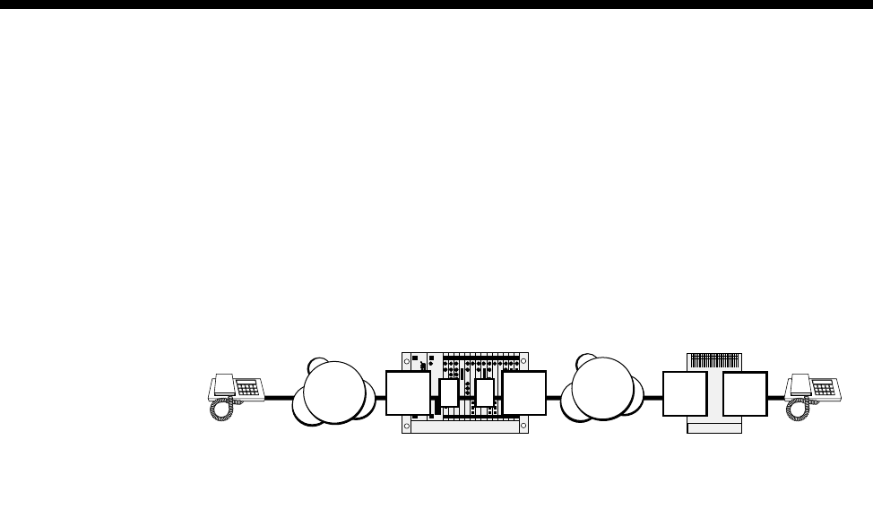
Applications 5-35
© 1993–2000 Jtec Pty Limited
The configuration described above only supports one call at a time. To support
multiple calls, create a lineset that has one half of the Interwork unit as its members.
Then set the lineset Min and Max numbers to 4811111. If you wish to support a range
of phone numbers, set the lineset Min and Max numbers accordingly.
Using remote tie line to make switched calls
This application can be used for bridging two networks, where tie lines operate across
one network and switched calls across the other. This application can also provide
tie lines with access to local switched calls on the same network.
Configuration
VX Node A
Configure the VX as follows:
1 Install one Interwork unit.
2 If ISDN A and B are different networks, set Outgoing TE to Exclusive.
3 Configure Interwork 1, Line 1 Left to have:
•Bearer Capability set to Speech A-law.
4 Configure Interwork 1, Line 1 Right to have:
•Line number configured to 4811111
•Auto answer set to On
•End-to-end signalling set to On.
VX Node B
1 Set the ALEM port to have:
•Hotline number set to 4811111
•Hotline enabled
•End-to-end set to On
•XSPC set to On.
Operation
The configuration of the ALEM port in the Node B causes a call to be established
between the ALEM and the Interwork 1, Line 1 Right. This call also carries the IDAS
end-to-end signalling.
LRIPMT
B
ISDN A
J1500 Access Controller
J1500 Access Controller
ISDN B
VX Node A
IPMT
or
BRMT
ALEM
VX Node B
Switched calls SPC or XSPC
connections with
end-to-end signalling
Note: ISDN A and ISDN B can be the same network.
If this is the case, IPMT A and IPMT B can be the
same ISDN interface
IPMT
A
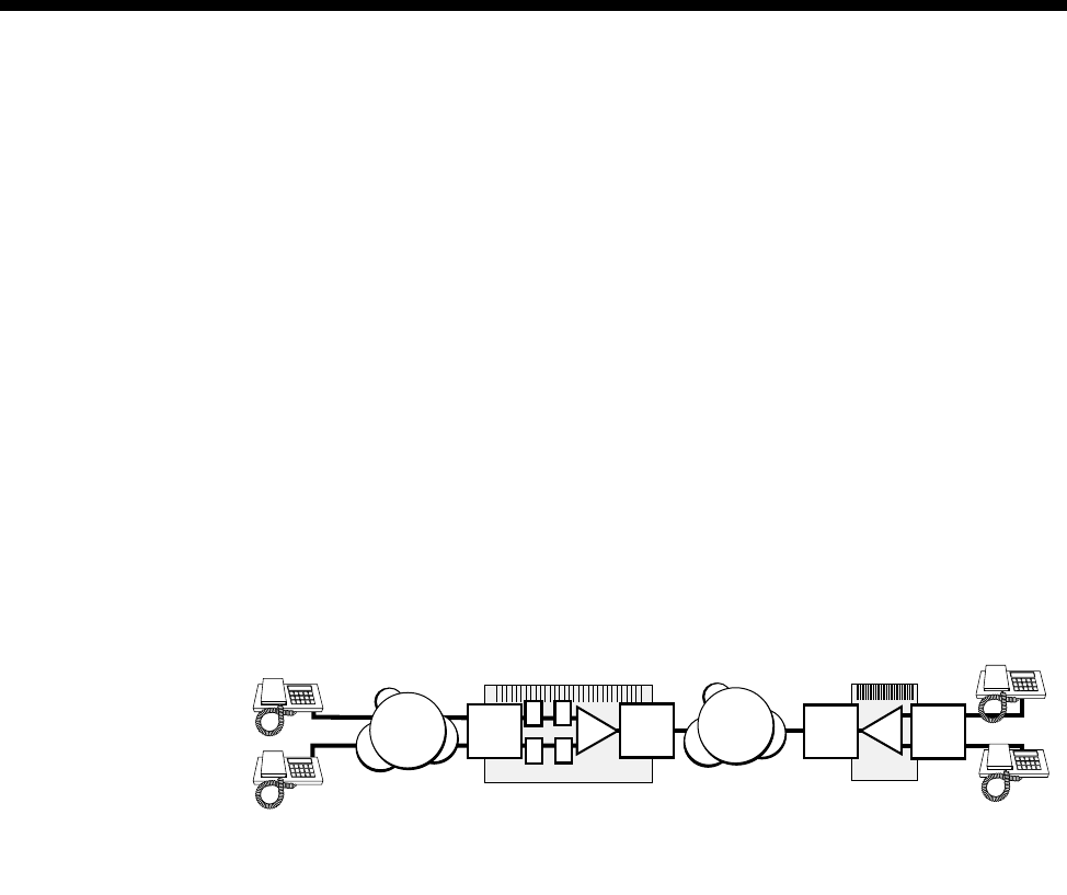
5-36 Interworking applications
10003497.00 Rev.5
When the handset connected to the ALEM in the VX Node B goes off-hook, an IDAS
setup message is sent to the Interwork 1, Line 1 Right of VX Node A. This is passed
to the Interwork 1, Line 1 Left, which issues a setup message to ISDN A. Any
signalling that is received from ISDN A is reflected back in IDAS messages to the
ALEM. When digits are dialled into the ALEM, they are carried over IDAS to the
Interwork 1, Line 1 Right, which then translates them into ISDN dialling information.
When the handset goes on-hook, the switched call is cleared.
If call progress tones are not provided by ISDN A, they can be provided by VX Node
A. To enable VX Node B tones, enable E2E Service tones for the Interwork 1, Line 1
Right.
Compressed tie lines to switched calls
This application is similar to the previous one and can also be used when bridging
two networks where tie lines operate across one network and switched calls across
the other. Similarly, it can provide tie lines with access to local switched calls on the
same network. In this particular case, two voice lines share the one tie line using voice
compression.
Configuration
VX Node A
Configure the VX as follows:
1 Install one Interwork unit.
2 If ISDN A and ISDN B are different networks, set Outgoing TE to Exclusive.
3 Create a Subrate Virtual Line with Interwork 1, Line 1 Right and Interwork 1, Line
2 Right as its members. Allocate 32 kbit/s to each line.
4 Configure the TimeFrame or Subrate Virtual Line to have:
•Auto answer set to On.
•End-to-end set to On.
5 Configure Interwork 1, Line 1 Left to have:
•Bearer Capability set to Speech A-law.
6 Configure Interwork 1, Line 2 Left to have:
•Bearer Capability set to Speech A-law.
J1500 Access Controller
J1500 Access Controller
VX Node A VX Node B
Switched calls SPC or XSPC
connections with
end-to-end signalling
Note: ISDN A and ISDN B can be the same network.
If this is the case, IPMT A and IPMT B can be the
same ISDN interface
VCM
ISDN A IPMT
A
LR
LR
IPMT
BISDN B IPMT
or
BRMT VCM ALEM

Applications 5-37
© 1993–2000 Jtec Pty Limited
7 Configure Interwork 1, Line 1 Right to have:
•SPC set to On (Australia only).
•Member of Subrate Virtual Line or manually connected mode set to On (UK
only).
•End-to-end signalling set to On.
8 Configure Interwork 1, Line 2 Right to have:
•SPC set to On (Australia only).
•Member of Subrate Virtual Line or manually connected mode set to On (UK
only).
•End-to-end signalling set to On.
VX Node B
Configure the VX as follows:
1 Create a Subrate Virtual Line with the two ALEM lines as its members. Allocate
32 kbit/s to each line.
2 Configure the Subrate or TimeFrame Virtual Line to have:
•Hotline number set to 4811111.
•Hotline enabled.
•End-to-end set to On.
•XSPC mode set to On.
3 Configure both ALEM lines to have:
•End-to-end set to On.
Operation
The configuration of the Subrate or TimeFrame Virtual Line in VX Node B causes a
call to be established between it and the Virtual Line in VX Node A. This call also
carries the IDAS end-to-end signalling.
When one of the handsets connected to the ALEM in VX Node B goes off-hook, an
IDAS setup message is sent to Interwork 1, Line 1 Right in VX Node A. This is passed
to Interwork 1, Line 1 Left, which issues a setup message to ISDN A. Any signalling
that is received from ISDN A is reflected back in IDAS messages to the ALEM. When
digits are dialled into the ALEM, they are carried over IDAS to the Interwork unit in
VX Node A, which then translates them into dialling information. When the handset
goes on-hook, the switched call is cleared.
The two handsets can operate independently, while sharing the same B-channel
through ISDN B.
If call progress tones are not provided by ISDN A, they can be provided by VX Node
A. To enable VX Node B tones, enable E2E Service tones for the Interwork 1, Line 1
Right and Interwork 1, Line 2 Right.
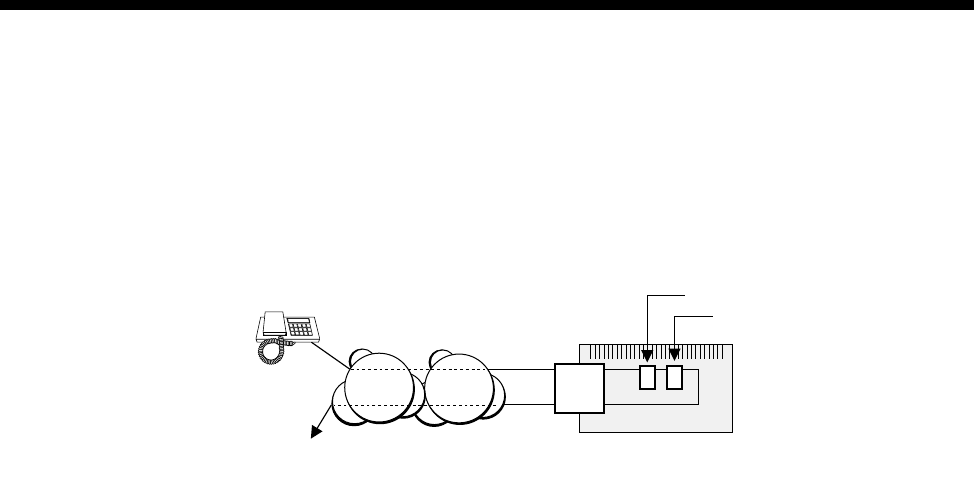
5-38 Interworking applications
10003497.00 Rev.5
Local call to an international number
This application allows you to make local calls which relay onto an international call
to a predetermined destination. This may be useful to provide a toll-free international
access to customers.
Configuration
1 Install one Interwork unit.
2 Configure Interwork 1, Line 1 Left to have:
•Line number set to 4811111
•Indial mode set to On.
3 Configure Interwork 1, Line 1 Right to have:
•Hotline number set to 0011442238081
•Hotline enabled.
Operation
An incoming call from a subscriber in the ISDN or PSTN to 4811111 will be directed
to Interwork 1, Line 1 Left. This causes an outgoing call setup to be issued by
Interwork 1, Line 1 right to 0011 44 223 8081. This call has the same ISDN information
elements as the incoming call. All signalling, that is, Alerting, Connect, Disconnect
and so on, received from the ISDN for the outgoing call is reflected back to the
incoming call. When one party clears their call, the other is also cleared.
Multiple calls
The configuration described above supports only one call at a time. To support up to
30 calls, do not set the line number for Interwork 1, Line 1 Left. Instead, create a lineset
with 4811111 for both the Minimum and Maximum numbers. Add the whole of the
Interwork 1, Left to the lineset. Turn off Indial in all Interwork 1, Left lines and
configure the Hotline number and Hotline mode for all Interwork 1, Right lines. To
support 30 calls at a time, two IPMTs have to be fitted because each Interworking
operation requires both an incoming and an outgoing call.
VX
ISDN
PSTN IPMT
or
BRMT
R
L
Subscriber makes
a local call to
481 1111
International call to
0011 44 223 8081
Line number = 481 1111
Hotline number = 0011 44 223 8081

Applications 5-39
© 1993–2000 Jtec Pty Limited
CallBack
CallBack is a useful feature that takes advantage of lower tariffs that may be available
in one location. The feature allows a call to be set up from one end of a network,
regardless of where the call originates. This ensures that only one end of the network
pays for call charging. CallBack uses interworking units to set up the required
signalling and call charging.
The feature can be used for compressed calls involving Subrate and TimeFrame
Virtual Lines as well as non-compressed data calls. Non-compressed voice calls have
limited support using CallBack. Non-compressed voice calls can be used if the
application requires the appropriate voice port to be set to Auto Answer at the
CallBack Originating end, with the connected device (e.g. PBX) providing the
appropriate tones. An example of where CallBack could be used in this scenario is
with Virtual eXtension (see page 5-86). CallBack can only be used for demand
established calls.
When making a CallBack, the RM examines the incoming CLI and, if present, uses
that to establish the call back to the initiating end. This allows multiple remote sites
to call into a single CallBack site. If no CLI is present or the CBack Hotline is set, the
Hotline Number in the CallBack Originating Right Hand End Interwork Unit is used
to establish the CallBack.
The CLI Number Checking feature (see page 3-49) can be used to provide additional
security on calls for networks where CLI is provided.
Note CLI is not provided on all international calls. In this case security may be a concern.
When using CallBack on a QBRM, the option Send Calling Party Number must be
enabled in the configuration dialog in OmniVision. See page 4-27 for details on
configuring the QBRM.
Note For CallBack trunks carrying compressed voice that are initiated from the end
nominated as the destination, the first voice call will take longer to establish than subsequent
calls due to the time involved in making a call, clearing it and then calling back from the other
end to establish the trunk.
RM
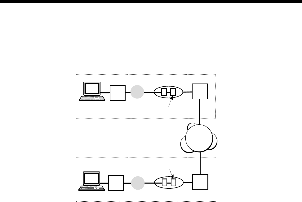
5-40 Interworking applications
10003497.00 Rev.5
Non compressed data call
The following diagram shows a typical implementation for a non-compressed data
call with no end-to-end signalling.
In the above scenario, Party A is the one selected to receive the billing for any calls
occurring between the two parties. If Party A initiates a call, the call signalling setup
occurs normally and either party can clear the call. If Party B initiates the call, the
setup signal is detected by the Party A Interworking Unit and the call is setup in the
opposite direction. Again either party can clear the call.
Configuration - Party A
To configure the CallBack feature for Party A:
1 Configure a lineset and direct it to the Interworking Unit (IWU) chosen for the
CallBack feature.
2 In the chosen IWU line (right) Call Establishment Modes, enable the CallBack
Orig checkbox. Enable and enter the Hotline number towards the B party IWU
(right).
3 In the chosen IWU line (left) enable and enter the Hotline number towards the
DLM port.
4 Select the Outgoing TE for the line.
TE
VX
LR
IWU
IWU
Enable “Callback Orig”
Enable “Callback Dest”
TE
VX
LR
Network
DLM
DLM
Party A
Party B
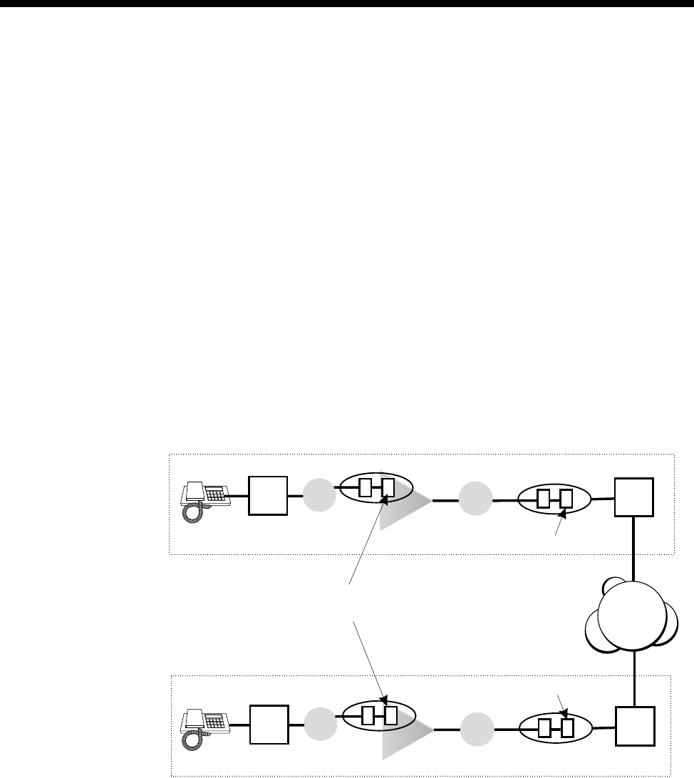
Applications 5-41
© 1993–2000 Jtec Pty Limited
Configuration - Party B
To configure the CallBack feature for Party B:
1 Configure a lineset and direct it to the Interworking Unit (IWU) chosen for the
CallBack feature.
2 In the chosen IWU line (right) Call Establishment Modes, enable the CallBack
Dest checkbox. Enable and enter the Hotline number towards the A party IWU
(right).
3 In the chosen IWU line (left) enable and enter the Hotline number towards the
DLM port.
4 Select the Outgoing TE for the line.
Compressed call using Virtual Line
The following diagram shows a typical implementation of CallBack for a compressed
call using a Virtual Line
In this scenario, compressed calls are implemented. Party A is the one selected to
receive the billing for any calls occurring between the two parties. If Party A initiates
a call, the call signalling setup occurs normally and either party can clear the call. If
Party B initiates the call, the setup signal is detected by the Party A Interworking Unit
and the call is setup in the opposite direction. Again either party can clear the call.
Because the call has to pass through more than one VX, additional configuration is
required.
VX TE
VX
LR
LR
VL
VL
IWU
IWU
IWU
IWU
Enable end-to-end signalling
Enable “End-to-end service tones”
Enable “Callback Orig”
Enable “Callback Dest”
VX TE
VX
LR
Network
ALEM
ALEM
Party A
Party B
LR

5-42 Interworking applications
10003497.00 Rev.5
Configuration - Party A
To configure the CallBack feature for Party A:
1 Configure a Subrate Virtual Line and direct it to an Interworking Unit (IWU).
2 In the chosen IWU line (right) Call Establishment Modes, enable the CallBack
Orig checkbox. Enable and enter the Hotline Number towards the B party IWU
(right).
Enable CBack Hotline if you prefer to use the Hotline Number for the CallBack,
rather than the CLI of the CallBack Dest. This is generally used when the received
CLI has been altered by the network, which can happen when CallBack is used
across international boundaries.
3 In the chosen IWU line (left) enable and enter the Hotline number in the direction
of the Virtual line.
4 In the Virtual Line IWU (right) Common Configuration, enable End-to-end
signalling and End-to-end service tones.
5 Select the Outgoing TE for the line.
Configuration - Party B
To configure the CallBack feature for Party B:
1 Configure a lineset and direct it to the Interworking Unit (IWU) chosen for the
CallBack feature.
2 In the chosen IWU line (right) Call Establishment Modes, enable the CallBack
Dest checkbox. Enable and enter the Hotline number towards the A party IWU
(right).
3 In the chosen IWU line (left) enable and enter the Hotline number in the direction
of the Virtual line.
4 In the Virtual Line IWU (right) Common Configuration, enable End-to-end
signalling and End-to-end service tones.
5 Select the Outgoing TE for the line.
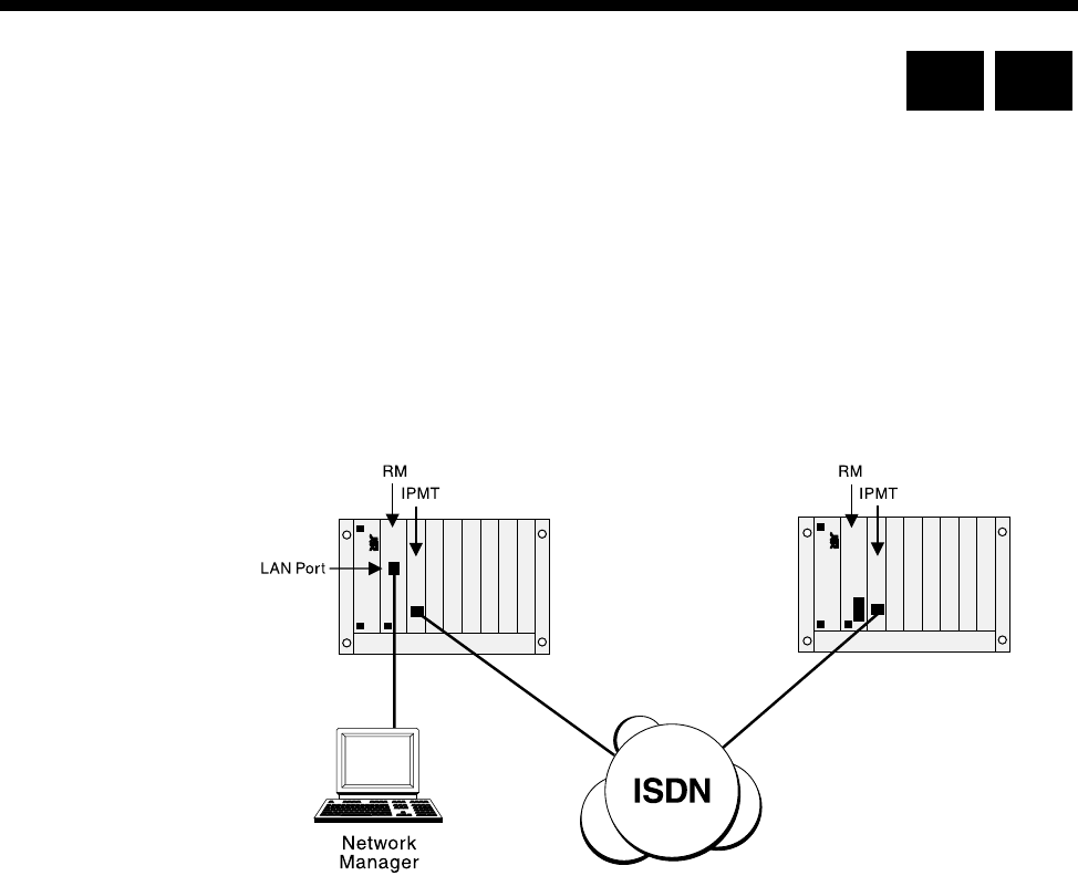
Applications 5-43
© 1993–2000 Jtec Pty Limited
Inband signalling applications
This section details two ways of connecting and configuring the equipment to use
inband signalling. For a fuller explanation of this feature see page 3-43 in the System
configuration section.
Simple point-to-point connection
This example shows a simple point-to-point connection involving two nodes and an
ISDN call.
Configuration details
The routing table for the local node is configured to use the backplane router port of
the Resource Manager (RM) or Control Module (CM) as the primary route. This port
has a Hotline number so that when a connection is required, a B-channel call will be
made to the remote node.
Where D-channel calls are available, the secondary route uses one of the D-channel
routing ports of the Local node. If the primary route fails, a D-channel call is made to
the remote node.
The configuration details for each node are as follows:
Local node
SAM (CM/RM) inband:
•Set to 8 kbit/s
•Set Hotline number. For example, 3840050.
Local node Remote node
RM CM

5-44 Inband signalling applications
10003497.00 Rev.5
SAM (CM/RM) D-channel 1: (Australia only)
•Set Hotline number. For example 3840050.
CM/RM-SAM routing table
Remote node
SAM (CM/RM) inband:
•Set to 8 kbit/s.
Manager access number
•Enter the manager access number. For example, 3840050.
Addresses Primary route Secondary route
3840050 SAM (CM/RM) inband SAM (CM/RM) D-channel 1
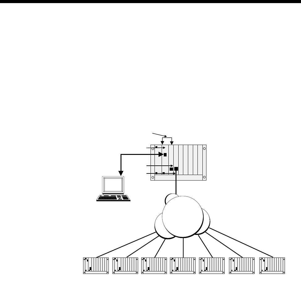
Applications 5-45
© 1993–2000 Jtec Pty Limited
Simple tree network
The following example shows a scenario where a SAM module is used at the central
site to enable OmniVision to manage remote nodes at several branch offices. Each
link is 8 kbit/s and can share the B-channel with compressed voice circuits or other
data channels.
More branch offices can be added by using more SAMs to the central site chassis, or
by adding SAMs to one or more of the branch offices. The latter method allows the
remote nodes to be connected to other remote offices.
Configuration details
The network is configured as follows:
Central site node
SAM (CM) inband: Set to 8 kbit/s
SAM inb 1: Set to 8 kbit/s
SAM inb 2: Set to 8 kbit/s, Hotline = 3900100
SAM inb 3: Set to 8 kbit/s, Hotline = 3900200
SAM inb 4: Set to 8 kbit/s, Hotline = 3900300
SAM inb 5: Set to 8 kbit/s, Hotline = 3900400
SAM inb 6: Set to 8 kbit/s, Hotline = 3900500
SAM inb 7: Set to 8 kbit/s, Hotline = 3900600
SAM inb 8: Set to 8 kbit/s, Hotline = 3900700
Network
Manager
Central Site
Node
Remote Nodes
CM
SAM
Manual TDM
backplane connection
ISDN
IPMT
NMS access number
3900100 39007003900500 3900600390040039003003900200

5-46 Inband signalling applications
10003497.00 Rev.5
CM/RM-SAM routing table:
SAM routing table:
Manual connection: SAM (CM/RM) inband to SAM inb 1.
Remote nodes
All remote nodes are configured with their respective Manager access numbers.
Addresses Primary route
3900100 — 3900700 SAM (CM/RM) inband
Addresses Primary route
3900100 SAM inb 2
3900200 SAM inb 3
3900300 SAM inb 4
3900400 SAM inb 5
3900500 SAM inb 6
3900600 SAM inb 7
3900700 SAM inb 8
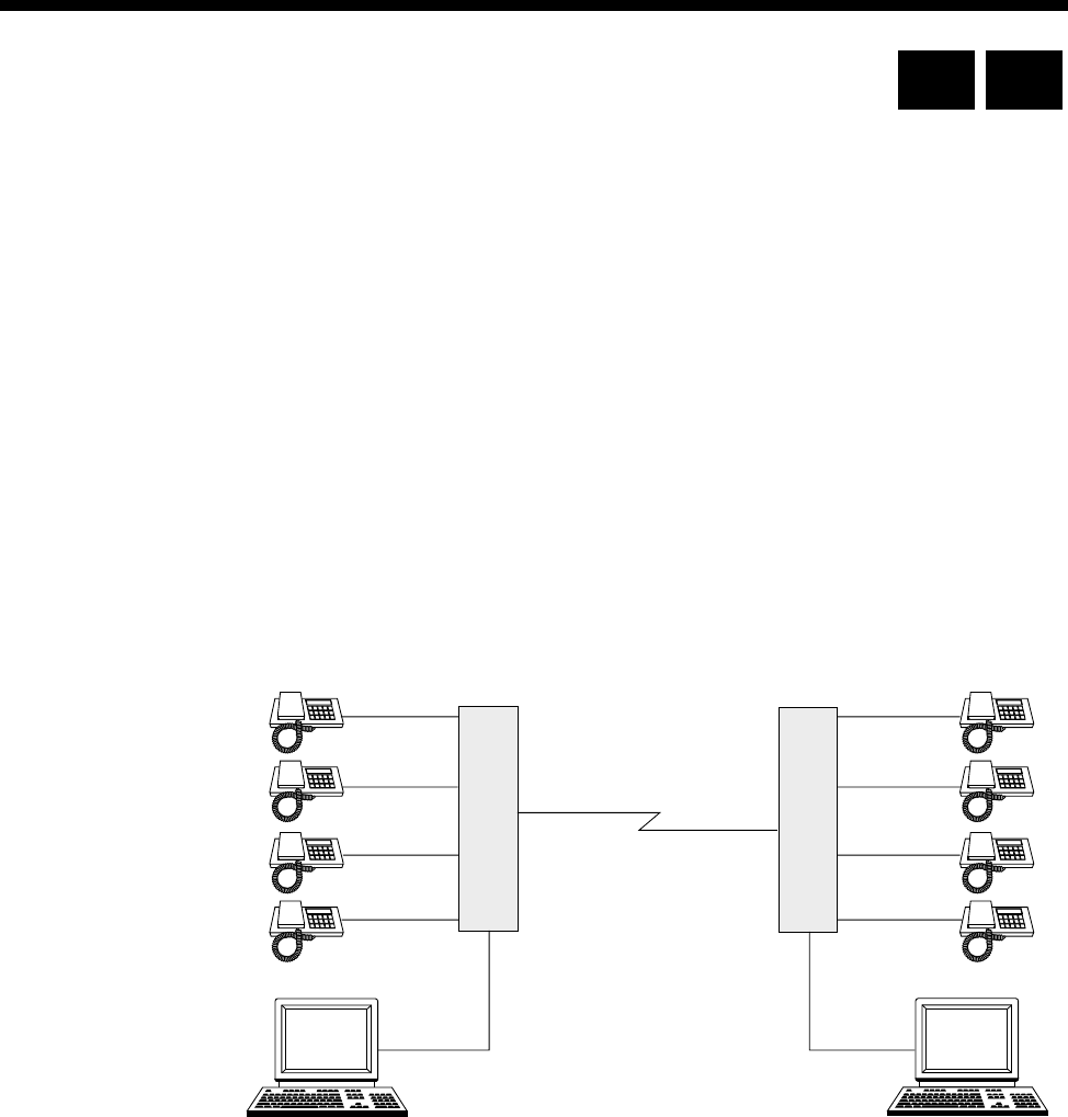
Applications 5-47
© 1993–2000 Jtec Pty Limited
LDCM and MFCM applications
This section details several applications for both the LDCM and MFCM. For details
of the operation and configuration of the LDCM see page 4-189 of the Modules section.
For the same information on the MFCM see page 4-193 of the Modules section. All of
the following applications can be performed with the CELP and MP-MLQ versions
of the LDCM. Apart from the last application with the VCM, all other applications
can be performed with the MFCM.
Tie line application
The LDCM and MFCM can be used where voice tie lines are needed between
members of the this equipment series. The modules allows the voice signals to be
compressed and switched onto a common channel, thus using fewer network access
channels.
Where data leased lines are also needed between the sites, the voice and data
sub-channels can be multiplexed together using the Subrate multiplexer. The
following diagram depicts the concept:
LDCM
or
MFCM
LDCM
or
MFCM
64 kbit/s
64 kbit/s
64 kbit/s
64 kbit/s
64 kbit/s
64 kbit/s
64 kbit/s 64 kbit/s
19.2 kbit/s 19.2 kbit/s
64 kbit/s
= 4x8 kbit/s (voice)
+32 kbit/s (data)
RM CM
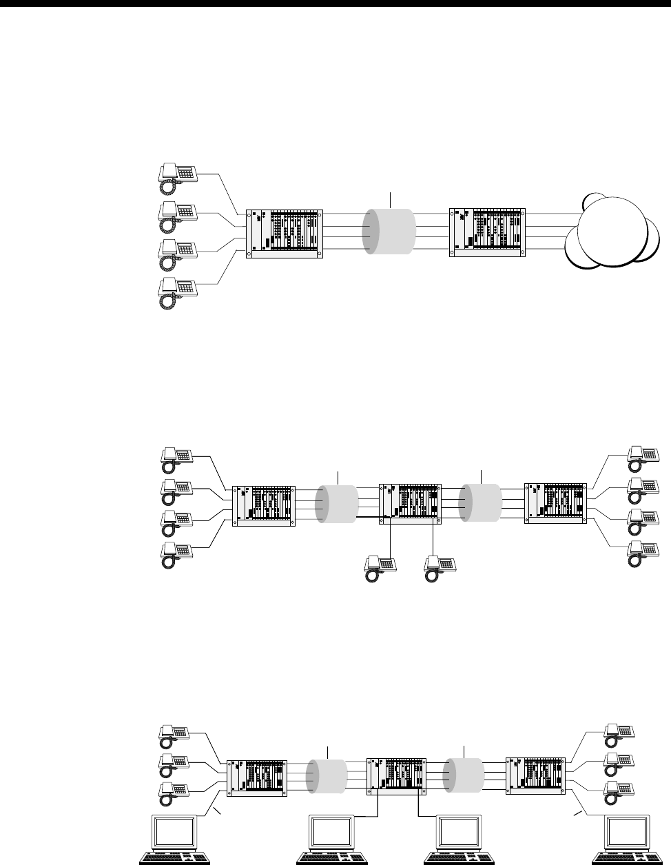
5-48 LDCM and MFCM applications
10003497.00 Rev.5
Private network with access to PTN
The following diagram shows how a private voice network can be constructed with
access to the public network.
Transit node - voice only application
The following diagram shows how a private voice network can be constructed with
a transit node drop and insert.
Transit node — voice / data application
The following diagram shows a compressed voice/data network with transit node
drop and insert for data only. Note that the transit node does not require an LDCM
or MFCM, but only an SRMM.
PTN
Chassis with
LDCM or MFCM Chassis with
LDCM or MFCM
64 Kbit/s channel
with 4 x 16 kbit/s
subchannels
Chassis with
LDCM or MFCM
Chassis with
LDCM or MFCM
Chassis with
LDCM or MFCM
64 Kbit/s channel
with 4 x 16 kbit/s
subchannels
64 Kbit
/
s channel
with 4 x 16 kbit/s
subchannels
Chassis with
LDCM or MFCM Chassis with
SRMM Chassis with
LDCM or MFCM
64 Kbit/s channel
with 4 x 16 kbit/s
subchannels
64 Kbit/s channel
with 4 x 16 kbit/s
subchannels
9600 bit/s async 9600 bit/s async
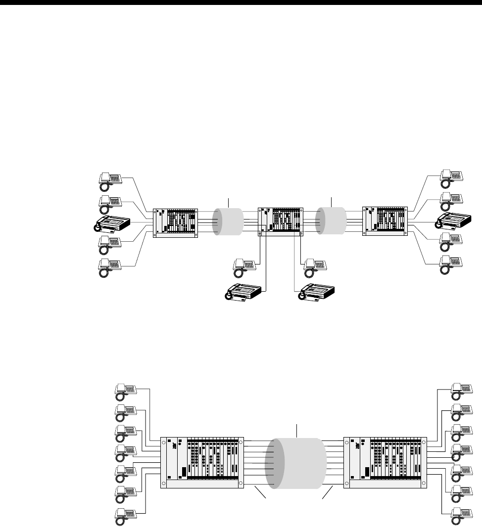
Applications 5-49
© 1993–2000 Jtec Pty Limited
Transit node — voice /fax network application
The following diagram shows how a private voice/fax network can be constructed
with a transit node drop and insert. This example shows a main office in Sydney and
branch offices in Melbourne and Brisbane. The Sydney node acts as a transit node, so
that any calls for Sydney from Melbourne or Brisbane are off-loaded (drop). If the call
is for one of the other offices, that is Melbourne is calling Brisbane or vice versa,
Sydney calls (insert) the respective destination.
Application with Signalling Access Module (SAM)
The following diagram shows a compressed voice network with inband (SAM)
signalling:
Chassis with
LDCM or MFCM Chassis with
LDCM or MFCM Chassis with
LDCM or MFCM
64 Kbit/s channel
with 5 x 8 kbit/s
subchannels
64 Kbit/s channel
with 5 x 8 kbit/s
subchannels
MELB SYD BRIS
Chassis with
LDCM/MFCM
and SAM
Chassis with
LDCM/MFCM
and SAM
64 Kbit/s channel
with 8 x 8 kbit/s
subchannels
8 kbit/s signalling
subchannel
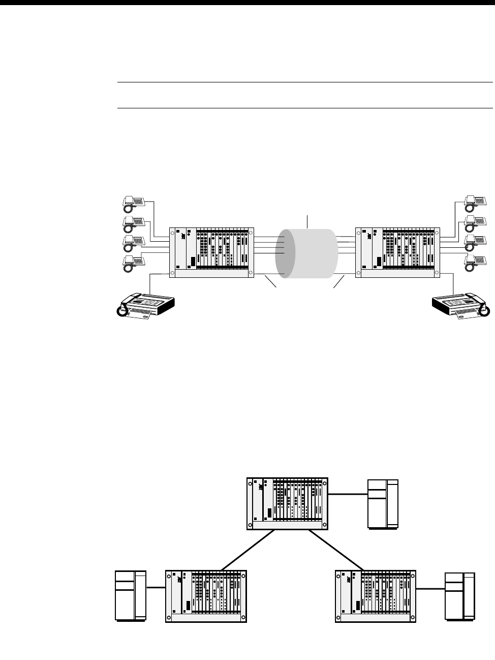
5-50 LDCM and MFCM applications
10003497.00 Rev.5
Application with VCM
Note The MFCM cannot be used with his application.
The following diagram shows a compressed voice network with an LDCM for CELP
compression of voice channels and a VCM for ADPCM compression of a full speed
(that is, 9600 bit/s analog modulated) fax channel:
Mixed TimeFrame Network with HD-VCMs and MLQ-CMPs
You should give special consideration to networks that contain MFCMs with both
HD-VCM and MLQ-CMP submodules. The main issue is the maintenance of
compatibility rules for TimeFrame Virtual Lines. The following diagram shows a
network that contains MFCMs equipped with both sorts of compression submodules.
In this network, a voice call can be established from Branch Office 1 to the Central
Site across TimeFrame. The call cannot be made to Branch Office 2 because it does
not have an MFCM fitted with MLQ-CMP submodules.
Chassis
with LDCM
and VCM
Chassis
with LDCM
and VCM
64 Kbit/s channel
with 4 x 8 kbit/s
subchannels
and one 32 kbit/s
subchannnel
32 kbit/s
subchannel
through VCMs
PABX
PABX PABX
Branch Office 1
Chassis fitted with
MFCM/ MLQ-CMP
Central Site
Chassis fitted with
1 x MFCM/ MLQ-CMP
1 x MFCM/HD-VCM
Branch Office 2
Chassis fitted with
MFCM/ HD-VCM
TimeFrame
Virtual Line TimeFrame
Virtual Line

Applications 5-51
© 1993–2000 Jtec Pty Limited
For similar reasons, Branch Office 2 can call the Central Site across TimeFrame, but
cannot establish a call to Branch Office 1. In this case, Branch Office 1 does not have
an MFCM with HD-VCMs.
The Central Site can call either Branch office across TimeFrame because it has both
types of MFCM.
To set up this network to allow a site to call any other site, an MFCM fitted with
HD-VCMs must be added to Branch Office 1. Alternatively, an MFCM fitted with
MLQ-CMPs can be installed at Branch Office 2.
It is important to verify that the two end points of a call involving TimeFrame Virtual
Lines have the same voice compression algorithms available. For more information
refer to the MFCM section on page 4-193.
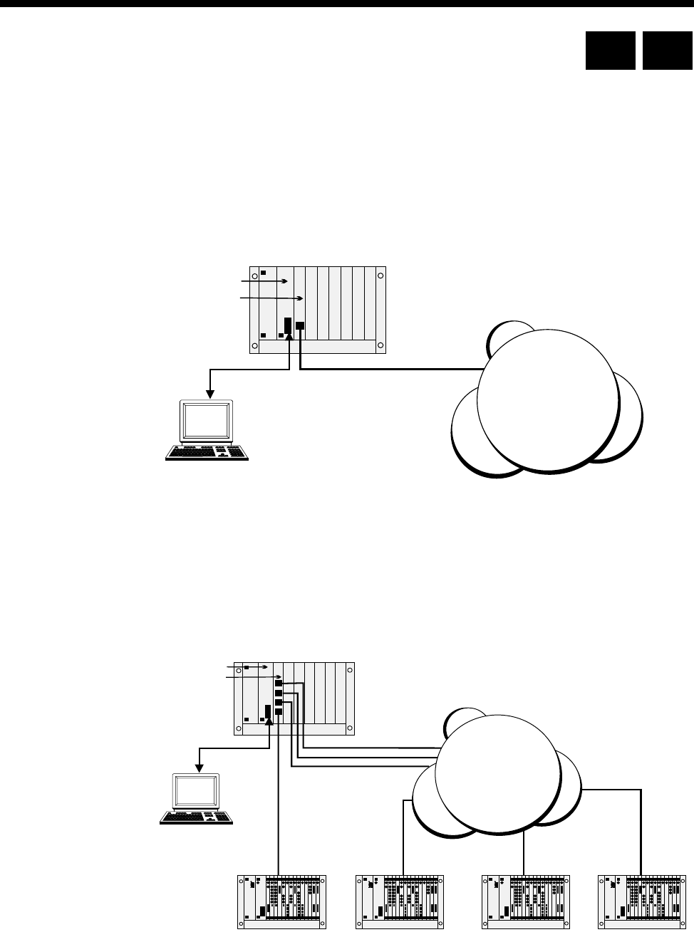
5-52 Digital Trunk Module (DTM) applications
10003497.00 Rev.5
Digital Trunk Module (DTM) applications
Overview
As with any other module, you configure the DTM using a Network Management
PC connected to the CM or RM. The DTM provides a service similar to that provided
by an IPM. As such, examples given in this section will highlight DTM-specific
features only and how they are used. More comprehensive network configuration
examples can be found in Virtual eXchange on page 5-30.
Remote Configure (Autosynchronise)
A Network Management PC locally connected to a chassis can use the D- or
B-channels to establish remote sessions with other nodes. This feature is preserved
with DTM connected nodes. The subB-channel cannot support Network
Management calls. The diagram below depicts this scenario.
RM
DTM
Network
Manager
X.21/V.35
Digital
Network
RM
DTM
Network
Manager
X.21/V.35
Digital
Network
RM CM

Applications 5-53
© 1993–2000 Jtec Pty Limited
The local node should have the local DTM port configured for the corresponding
network clock speed and so on. When an unconfigured chassis is powered up at a
remote site, the DTM ports enter an Automatic Synchronisation mode, where clock
and D-channel speeds are automatically determined (ensure the local DTM port is
idle) and frame synchronisation is achieved. Once frame synchronisation is
established, remote sessions can proceed as normal.
Notes
•When using the D-channel of a DTM for remote Network Management sessions, a fast
D-channel will improve performance.
•If the DTM port that is providing the remote Network Management session path requires
a configuration change that would cause a synchronisation loss, perform the remote
change first. Synchronisation will be lost. You then configure the local DTM port for the
change and restart the remote Network Management session.
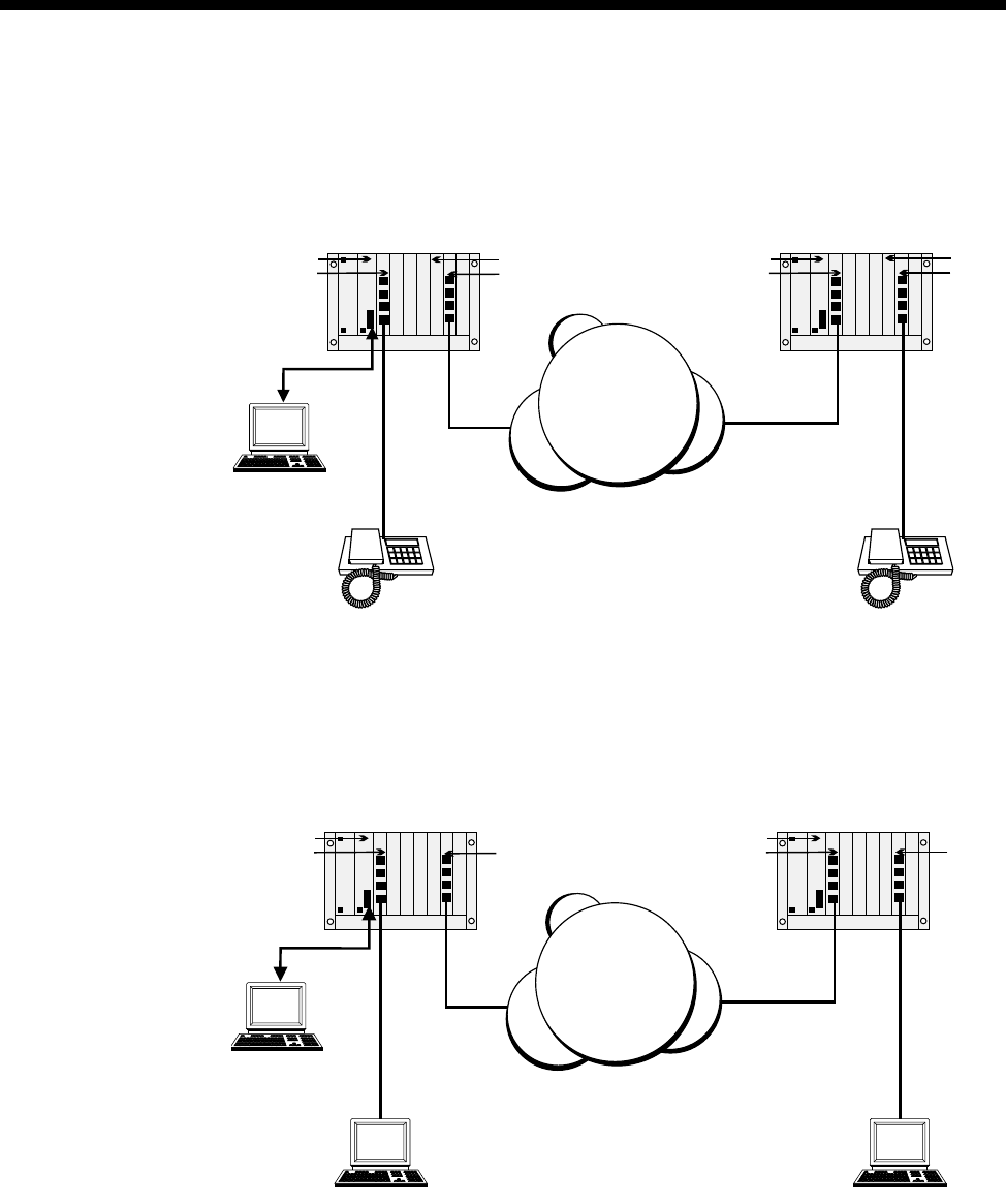
5-54 Digital Trunk Module (DTM) applications
10003497.00 Rev.5
Using the subB-channel
The subB-channel provides up to 56 kbit/s, that is, up to 7 bits of the full 8 bits per
octet. This means that Subrate Lines, Subrate Virtual Lines and TimeFrame Virtual
Lines can be used in the subB-channel, up to its configured speed. Every 8 kbit/s of
subB speed corresponds to one bit (starting from Bit 7). Refer to subB-channel usage
on page 4-85.
The subB-channel can also be used directly for Subrate speed digital connections, that
is, without a Subrate multiplexing module. Ensure that the Digital Line Module has
configured a V.110 Subrate. This Subrate shall be less than or equal to the subB speed.
RM
ALEM
Network
Manager
DTM DTM
RM
ALEM
VCM VCM
X.21/V.35
Digital
Network
RM
QDLM
Network
Manager
User 1
User 2
DTM DTM
RM
QDLM
X.21/V.35
Digital
Network
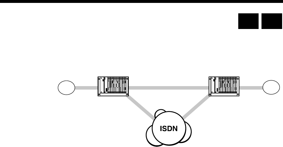
Applications 5-55
© 1993–2000 Jtec Pty Limited
DPNSS applications
This section details the configuration required for the following sample two node
network.
PABX A can dial 2 types of numbers:
•4200-4299 is used to reach extensions on PABX B.
•Anything else is used to reach numbers on the public network.
Similarly, PABX B can also dial 2 types of numbers:
•3900-3999 is used to reach extensions on PABX A.
•Anything else is used to reach numbers on the public network.
Three alternative configurations are listed:
•A 64K uncompressed network
•32K ADPCM voice compression on demand
•32K ADPCM manually connected.
The basic configuration is the same for each; only the Bandwidth Configuration is
different.
The following instructions assume you are starting with a defaulted configuration in
each node and subsequently lists only the things you have to change from default.
In this scenario the chassis, in addition to a Resource Manager/Control Module, and
Power Supply Unit, contains the following modules:
•IPMT-B190 in slot 1
•IPMN-ETSI in slot 3
•E1M-DPNSS in slot 5
•SAM in slot 10
•VCM in slot 15 (only required for the 32K examples).
VX Node
01865 449200-99
3900 - 3999 4200 - 4299
01223 352700-99
DPNSS
Node 1 Node 2
DPNSS
VX Node
VXTrunk
AB
RM CM

5-56 DPNSS applications
10003497.00 Rev.5
General configuration
Node 1
Node 2
DPNSS module configuration
Node 1
Node 2
Number Translation Configuration
Node 1
Node 2
NMS number 449298
Virtual eXchange Min 449200
Max 449299
Area code 1865
NMS number 352798
Virtual eXchange Min 352700
Max 352799
Area code 1223
Lineset 3900-3999 DPNSS 30-1
General settings A,X, Terrestrial
CPE Establishes
Min Number length 4
Lineset 4200-4299 DPNSS 30-1
General settings B,Y, Terrestrial
CPE Establishes
Min Number length 4
Number Range name OneTwo
Numbers 4200-4299 Apply to DPNSS called
Modify Replace with 01223352700
Apply to DPNSS Module Slot 5 All lines
Number Range name TwoOne
Numbers 3900-3999 Apply to DPNSS called
Modify Replace with 01865449200
Apply to DPNSS Module Slot 5 All lines

Applications 5-57
© 1993–2000 Jtec Pty Limited
Signalling configuration
Router tables
Node 1
Node 2
Signalling channels
Node 1
Node 2
CM/RM-SAM Number Range 01223352700-01223352799
Route selection Primary D-Channel 1 Secondary CM/RM Inband
SAM Number Range 01223352700-01223352799
Route selection Primary B-Channel 2 Secondary (none)
CM/RM-SAM Number Range 01865449200-01865449299
Route Selection Primary D-Channel 1 Secondary CM/RM Inband
SAM Number Range 01865449200-01865449299
Route Selection Primary B-Channel 2 Secondary (none)
CM/RM-SAM D-Channel 1 Line Number 449295
Hotline number 01223352795
Other Hotline mode
Auto Answer on
Acknowledge off
SAM B-Channel 2 Line Number 449296
Hotline number 01223352796
Other Hotline mode
Don’t use for i/c Manager
CM/RM-SAM D-Channel 1 Line Number 352795
Hotline number 01865449295
Other Hotline mode
Auto Answer on
Acknowledge off
SAM B-Channel 2 Line Number 352796
Hotline number 01865449296
Other Hotline mode
Don’t use for i/c Manager
5-58 DPNSS applications
10003497.00 Rev.5
Bandwidth Configuration
64K Uncompressed
Node 1
Node 2
* Note End of link should have the channel order reversed to minimise channel collisions.
Lineset Range 01223352700-01223352799
Members IPMN 3, 1-30 *
Attributes Non-Local
Lineset Range 01865449200-01865449299
Members IPMN 3, 30-1 *
Attributes Non-Local

Applications 5-59
© 1993–2000 Jtec Pty Limited
32K Compressed on demand
Only four channels (two Virtual Lines) each way are shown in this example. To add
capacity add more Virtual Lines.
Add one interwork unit (30 lines) to each node.
Node 1
Virtual Line 1 OneTwo1 Members 0,1,1 0,1,2 (32K ADPCM)
Line Number 449281
Hotline Number 01223352781
Other Hotline mode
End To End
Use CM/RM-SAM
Virtual Line 2 OneTwo2 Members 0,1,3 0,1,4 (32K ADPCM)
Line Number 449282
Hotline Number 01223352782
Other Hotline mode
End To End
Use CM/RM-SAM
Virtual Line 3 TwoOne1 Members 0,1,5 0,1,6 (32K ADPCM)
Line Number 449283
Hotline Number 01223352783
Other Hotline mode
End To End
Use CM/RM-SAM
Virtual Line 4 TwoOne2 Members 0,1,7 0,1,8 (32K ADPCM)
Line Number 449284
Hotline Number 01223352784
Other Hotline mode
End To End
Use CM/RM-SAM
Lineset 1 Range 01223352700-01223352700
Members 0,0,1 0,0,2 0,0,3 0,0,4
Attributes Non-Local
Lineset 2 Range 01223352701-01223352799
Members IPMN 3, 1-30
Attributes Non-Local

5-60 DPNSS applications
10003497.00 Rev.5
Node 2
Virtual Line 1 OneTwo1 Members 0,1,1 0,1,2 (32K ADPCM)
Line Number 352781
Hotline Number 01865449281
Other Hotline mode
End To End
Use CM/RM-SAM
Virtual Line 2 OneTwo2 Members 0,1,3 0,1,4 (32K ADPCM)
Line Number 352782
Hotline Number 01865449282
Other Hotline mode
End To End
Use CM/RM-SAM
Virtual Line 3 TwoOne1 Members 0,1,5 0,1,6 (32K ADPCM)
Line Number 352783
Hotline Number 01865449283
Other Hotline mode
End To End
Use CM/RM-SAM
Virtual Line 4 TwoOne2 Members 0,1,7 0,1,8 (32K ADPCM)
Line Number 352784
Hotline Number 01865449284
Other Hotline mode
End To End
Use CM/RM-SAM
Lineset 1
Range 01865449200-01865449200
Members 0,0,5 0,0,6 0,0,7 0,0,8
Attributes Non-Local
Lineset 2
Range 01865449201-01865449299
Members IPMN 3, 30-1 (Reversed)
Attributes Non-Local

Applications 5-61
© 1993–2000 Jtec Pty Limited
32K compressed manual connections
Only four channels (two Virtual Lines) each way are shown. To add capacity add
more Virtual Lines.
Add one interwork unit (30 lines) to each node.
Configuration tip Use Multi-Line configuration and Interwork Common
configurations to speed up the configuration process.

5-62 DPNSS applications
10003497.00 Rev.5
Node 1
Virtual Line 1 OneTwo1 Members 0,1,1 0,1,2 (32K ADPCM)
Other SPC Mode (AUS)
Manually Connected (UKS)
Virtual Line 2 OneTwo2 Members 0,1,3 0,1,4 (32K ADPCM)
Other SPC Mode (AUS)
Manually Connected (UKS)
Virtual Line 3 TwoOne1 Members 0,1,5 0,1,6 (32K ADPCM)
Other SPC Mode (AUS)
Manually Connected (UKS)
Virtual Line 4 TwoOne2 Members 0,1,7 0,1,8 (32K ADPCM)
Other SPC Mode (AUS)
Manually Connected (UKS)
Interwork 1 RHS 1 (0,1,1) Label AB#1
End to End Number 1223352700
Other SPC Mode (AUS)
Member of SRVL (UKS)
Transparent
End to End
Interwork 1 RHS 2 (0,1,2) Label AB#2
End to End Number 1223352700
Other SPC Mode (AUS
)Member of SRVL (UKS)
Transparent
End to End
Interwork 1 RHS 3 (0,1,3) Label AB#3
End to End Number 1223352700
Other SPC Mode (AUS)
Member of SRVL (UKS)
Transparent
End to End
Interwork 1 RHS 4 (0,1,4) Label AB#4
End to End Number 1223352700
Other SPC Mode (AUS)
Member of SRVL (UKS)
Transparent
End to End
Interwork 1 RHS 5 (0,1,5) Label AB#5
End to End Number 1223352700
Other SPC Mode (AUS)
Member of SRVL (UKS)
Transparent
End to End

Applications 5-63
© 1993–2000 Jtec Pty Limited
Node 2
Interwork 1 RHS 6 (0,1,6) Label AB#6
End to End Number 1223352700
Other SPC Mode (AUS)
Member of SRVL (UKS)
Transparent
End to End
Interwork 1 RHS 7 (0,1,7) Label AB#7
End to End Number 1223352700
Other SPC Mode (AUS)
Member of SRVL (UKS)
Transparent
End to End
Interwork 1 RHS 8 (0,1,8) Label AB#8
End to End Number 1223352700
Other SPC Mode (AUS)
Member of SRVL (UKS)
Transparent
End to End
Lineset 1 Range 01223352700-01223352700
Members 0,0,1 0,0,2 0,0,3 0,0,4
Attributes Non-Local
Lineset 2 Range 01223352701-01223352799
Members IPMN 3, 5-30 (missing 1-4!)
Attributes Non-Local
Manual Connection 1 Between OneTwo1
and B1 8,1,0 and 3,0,1
Type External, non-volatile, bi-directional
Manual Connection 2 Between
OneTwo2and B2 8,1,1 and 3,0,2
Type External, non-volatile, bi-directional
Manual Connection 3 Between TwoOne1
and B3 8,1,2 and 3,0,3
Type External, non-volatile, bi-directional
Manual Connection 4 Between TwoOne2
and B4 8,1,3 and 3,0,4
Type External, non-volatile, bi-directional
Virtual Line 1 OneTwo1 Members 0,1,1 0,1,2 (32K ADPCM)
Other SPC Mode (AUS)
Manually Connected (UKS)
Virtual Line 2 OneTwo2 Members 0,1,3 0,1,4 (32K ADPCM)
Other SPC Mode (AUS)
Manually Connected (UKS)

5-64 DPNSS applications
10003497.00 Rev.5
Virtual Line 3 TwoOne1 Members 0,1,5 0,1,6 (32K ADPCM)
Other SPC Mode (AUS)
Manually Connected (UKS)
Virtual Line 4 TwoOne2 Members 0,1,7 0,1,8 (32K ADPCM)
Other SPC Mode (AUS)
Manually Connected (UKS)
Interwork 1 RHS 1 (0,1,1) Label AB#1
End to End
Number 1865449200
Other SPC Mode (AUS)
Member of SRVL (UKS)
Transparent
End to End
Interwork 1 RHS 2 (0,1,2) Label AB#2
End to End
Number 1865449200
Other SPC Mode (AUS)
Member of SRVL (UKS)
Transparent
End to End
Interwork 1 RHS 3 (0,1,3) Label AB#3
End to End
Number 1865449200
Other SPC Mode (AUS)
Member of SRVL (UKS)
Transparent
End to End
Interwork 1 RHS 4 (0,1,4) Label AB#4
End to End
Number 1865449200
Other SPC Mode (AUS)
Member of SRVL (UKS)
Transparent
End to End
Interwork 1 RHS 5 (0,1,5) Label AB#5
End to End
Number 1865449200
Other SPC Mode (AUS)
Member of SRVL (UKS)
Transparent
End to End
Interwork 1 RHS 6 (0,1,6) Label AB#6
End to End
Number 1865449200
Other SPC Mode (AUS)
Member of SRVL (UKS)
Transparent
End to End

Applications 5-65
© 1993–2000 Jtec Pty Limited
Interwork 1 RHS 7 (0,1,7) Label AB#7
End to End
Number 1865449200
Other SPC Mode (AUS)
Member of SRVL (UKS)
Transparent
End to End
Interwork 1 RHS 8 (0,1,8) Label AB#8
End to End
Number 1865449200
Other SPC Mode (AUS)
Member of SRVL (UKS)
Transparent
End to End
Lineset 1 Range 01865449200-01865449200
Members 0,0,1 0,0,2 0,0,3 0,0,4
Attributes Non-Local
Lineset 2 Range 01865449201-01865449299
Members IPMN 3, 30-5 (missing 4-1!)
Attributes Non-Local
Manual Connection 1 Between OneTwo1
and B1 8,1,0 and 3,0,1
Type External, non-volatile, bi-directional
Manual Connection 2 Between OneTwo2
and B2 8,1,1 and 3,0,2
Type External, non-volatile, bi-directional
Manual Connection 3 Between TwoOne1
and B3 8,1,2 and 3,0,3
Type External, non-volatile, bi-directional
Manual Connection 4 Between TwoOne2
and B4 8,1,3 and 3,0,4
Type External, non-volatile, bi-directional
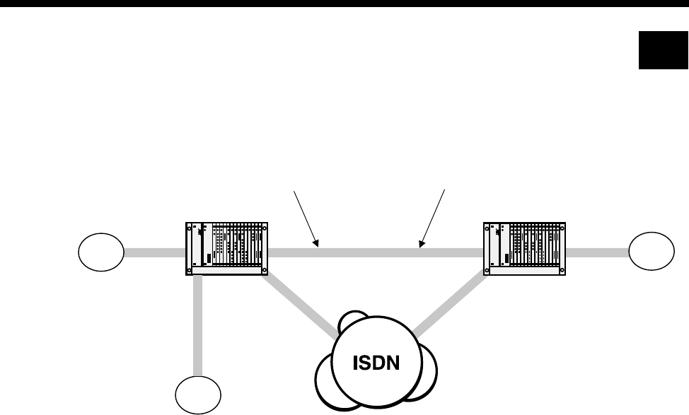
5-66 QSIG applications
10003497.00 Rev.5
QSIG applications
This section details the configuration required for the following sample two node
network.
PINX A can dial 3 types of numbers:
•4200-4299 is used to reach extensions on PINX B.
•5700-5799 is used to reach extensions on PINX C.
•Anything else is used to reach numbers on the public network.
Similarly, PINX B can also dial 3 types of numbers:
•3900-3999 is used to reach extensions on PINX B.
•5700-5799 is used to reach extensions on PINX C.
•Anything else is used to reach numbers on the public network.
VX
01865 449200-99
3900 - 3999
5700 - 5799
4200 - 4299
Lineset that routes to node 1
01865449200 -01865449299
01223 352700-99
Lineset that routes to node 2
01223352700 - 01223352799
QSIG
QSIG
Node 1 Node 2
QSIG
VX
VXTrunk
A
C
B
RM

Applications 5-67
© 1993–2000 Jtec Pty Limited
General configuration
In this scenario the chassis, in addition to an RM or CM, and a Power Supply Module,
contains the following modules:
•IPMN-B190 in slot 8
•IPMN-ETSI in slot 3
•E1M-QSIG in slots 5 and 6
•SAM in slot 10
•VCM in slot 15 (only required for the 32K examples).
The following instructions assume you are starting with a defaulted configuration in
each node and subsequently lists only the things you have to change from default.
Node 1
Node 2
QSIG module configuration - connected locally (PINX A to PINX C)
Node 1
*Order of line set members corresponds to A/B configuration option chosen.
Manager number 449298
Virtual eXchange Min 449200
Max 449299
Area code 1865
Manager number 352798
Virtual eXchange Min 352700
Max 352799
Area code 1223
Lineset 1 Range 3900-3999
Members QSIG Slot 5 1-30*
Attributes Local
General settings QSIG A/B configuration A
Exclusive/Preferred Exclusive channel
Min number length 4
Lineset 2 Range 5700-5799
Members QSIG Slot 6 30-1*
Attributes Local
General settings QSIG A/B configuration B
Exclusive/Preferred Exclusive channel
Min number length 4

5-68 QSIG applications
10003497.00 Rev.5
QSIG module configuration - connected across a network (PINX A to PINX B)
Three alternative configurations are listed:
•A 64K uncompressed network
•32K ADPCM voice compression on demand
•32K ADPCM manually connected.
The basic configuration is the same for each; only the Bandwidth Configuration is
different.
The following instructions assume you are starting with a defaulted configuration in
each node and subsequently lists only the things you have to change from default.
Node 1
Node 2
*Order of line set members corresponds to A/B configuration option chosen.
Lineset Range 3900-3999
Members QSIG 1-30*
Attributes Local
General settings QSIG A/B configuration A
Exclusive/Preferred Exclusive channel
Min number length 4
Lineset Range 4200-4299
Members QSIG 30-1*
Attributes Local
General settings QSIG A/B configuration B
Exclusive/Preferred Exclusive channel
Min number length 4

Applications 5-69
© 1993–2000 Jtec Pty Limited
Number Translation Configuration
Node 1
Node 2
Signalling configuration
Router tables
Node 1
Node 2
Number Range name OneTwo
Numbers 4200-4299 Apply to QSIG called
Modify Replace with 01223352700
Apply to QSIG Module Slot 5 All lines
Number Range name TwoOne
Numbers 3900-3999 Apply to QSIG called
Modify Replace with 01865449200
Apply to QSIG Module Slot 5 All lines
CM/RM-SAM Number range 01223352700-01223352799
Primary route D-channel 1
Secondary route CM/RM inband
SAM Number range 01223352700-01223352799
Primary route B-channel 2
Secondary route None
CM/RM-SAM Number range 01865449200-01865449299
Primary route D-channel 1
Secondary route CM/RM inband
SAM Number range 01865449200-01865449299
Primary route B-channel 2
Secondary route None

5-70 QSIG applications
10003497.00 Rev.5
Signalling channels
Node 1
Node 2
Bandwidth Configuration
64K Uncompressed
Node 1
Node 2
* Note End of link should have the channel order reversed to minimise channel collisions.
CM/RM-SAM D-Channel 1 Line Number 449295
Hotline number 01223352795
Other Hotline mode
Auto Answer on
Acknowledge off
SAM B-Channel 2 Line Number 449296
Hotline number 01223352796
Other Hotline mode
Don’t use for i/c Manager calls
CM/RM-SAM D-Channel 1 Line Number 352795
Hotline number 01865449295
Other Hotline mode
Auto Answer on
Acknowledge off
SAM B-Channel 2 Line Number 352796
Hotline number 01865449296
Other Hotline mode
Don’t use for i/c Manager calls
Lineset Range 01223352700-01223352799
Members IPMN 3, 1-30 *
Attributes Non-Local
Lineset Range 01865449200-01865449299
Members IPMN 3, 30-1 *
Attributes Non-Local

Applications 5-71
© 1993–2000 Jtec Pty Limited
32K Compressed on demand
Only four channels (two Virtual Lines) each way are shown in this example. To add
capacity add more Virtual Lines.
Add one interwork unit (30 lines) to each node.
Node 1
Virtual Line 1 OneTwo1 Members 0,1,1 0,1,2 (32K ADPCM)
Line Number 449281
Hotline Number 01223352781
Other Hotline mode
End To End
Use CM/RM-SAM
Virtual Line 2 OneTwo2 Members 0,1,3 0,1,4 (32K ADPCM)
Line Number 449282
Hotline Number 01223352782
Other Hotline mode
End To End
Use CM/RM-SAM
Virtual Line 3 TwoOne1 Members 0,1,5 0,1,6 (32K ADPCM)
Line Number 449283
Hotline Number 01223352783
Other Hotline mode
End To End
Use CM/RM-SAM
Virtual Line 4 TwoOne2 Members 0,1,7 0,1,8 (32K ADPCM)
Line Number 449284
Hotline Number 01223352784
Other Hotline mode
End To End
Use CM/RM-SAM
Lineset 1 Range 01223352700-01223352700
Members 0,0,1 0,0,2 0,0,3 0,0,4
Attributes Non-Local
Lineset 2 Range 01223352701-01223352799
Members IPMN 3, 1-30
Attributes Non-Local

5-72 QSIG applications
10003497.00 Rev.5
Node 2
Virtual Line 1 OneTwo1 Members 0,1,1 0,1,2 (32K ADPCM)
Line Number 352781
Hotline Number 01865449281
Other Hotline mode
End To End
Use CM/RM-SAM
Virtual Line 2 OneTwo2 Members 0,1,3 0,1,4 (32K ADPCM)
Line Number 352782
Hotline Number 01865449282
Other Hotline mode
End To End
Use CM/RM-SAM
Virtual Line 3 TwoOne1 Members 0,1,5 0,1,6 (32K ADPCM)
Line Number 352783
Hotline Number 01865449283
Other Hotline mode
End To End
Use CM/RM-SAM
Virtual Line 4 TwoOne2 Members 0,1,7 0,1,8 (32K ADPCM)
Line Number 352784
Hotline Number 01865449284
Other Hotline mode
End To End
Use CM/RM-SAM
Lineset 1
Range 01865449200-01865449200
Members 0,0,5 0,0,6 0,0,7 0,0,8
Attributes Non-Local
Lineset 2
Range 01865449201-01865449299
Members IPMN 3, 30-1 (Reversed)
Attributes Non-Local

Applications 5-73
© 1993–2000 Jtec Pty Limited
32K compressed manual connections
Only four channels (two Virtual Lines) each way are shown. To add capacity add
more Virtual Lines.
Add one interwork unit (30 lines) to each node.
Configuration tip Use Multi-Line configuration and Interwork Common
configurations to speed up the configuration process.
Node 1
Virtual Line 1 OneTwo1 Members 0,1,1 0,1,2 (32K ADPCM)
Other SPC Mode (AUS)
Manually Connected (UKS)
Virtual Line 2 OneTwo2 Members 0,1,3 0,1,4 (32K ADPCM)
Other SPC Mode (AUS)
Manually Connected (UKS)
Virtual Line 3 TwoOne1 Members 0,1,5 0,1,6 (32K ADPCM)
Other SPC Mode (AUS)
Manually Connected (UKS)
Virtual Line 4 TwoOne2 Members 0,1,7 0,1,8 (32K ADPCM)
Other SPC Mode (AUS)
Manually Connected (UKS)
Interwork 1 RHS 1 (0,1,1) Label AB#1
End to End
Number 1223352700
Other SPC Mode (AUS)
Member of SRVL (UKS)
Transparent
End to End
Interwork 1 RHS 2 (0,1,2) Label AB#2
End to End
Number 1223352700
Other SPC Mode (AUS
Member of SRVL (UKS)
Transparent
End to End
Interwork 1 RHS 3 (0,1,3) Label AB#3
End to End
Number 1223352700
Other SPC Mode (AUS)
Member of SRVL (UKS)
Transparent
End to End

5-74 QSIG applications
10003497.00 Rev.5
Interwork 1 RHS 4 (0,1,4) Label AB#4
End to End
Number 1223352700
Other SPC Mode (AUS)
Member of SRVL (UKS)
Transparent
End to End
Interwork 1 RHS 5 (0,1,5) Label AB#5
End to End
Number 1223352700
Other SPC Mode (AUS)
Member of SRVL (UKS)
Transparent
End to End
Interwork 1 RHS 6 (0,1,6) Label AB#6
End to End
Number 1223352700
Other SPC Mode (AUS)
Member of SRVL (UKS)
Transparent
End to End
Interwork 1 RHS 7 (0,1,7) Label AB#7
End to End
Number 1223352700
Other SPC Mode (AUS)
Member of SRVL (UKS)
Transparent
End to End
Interwork 1 RHS 8 (0,1,8) Label AB#8
End to End
Number 1223352700
Other SPC Mode (AUS)
Member of SRVL (UKS)
Transparent
End to End
Lineset 1 Range 01223352700-01223352700
Members 0,0,1 0,0,2 0,0,3 0,0,4
Attributes Non-Local
Lineset 2 Range 01223352701-01223352799
Members IPMN 3, 5-30 (missing 1-4!)
Attributes Non-Local
Manual Connection 1 Between OneTwo1
and B1 8,1,0 and 3,0,1
Type External, non-volatile, bi-directional
Manual Connection 2 Between OneTwo2
and B2 8,1,1 and 3,0,2
Type External, non-volatile, bi-directional

Applications 5-75
© 1993–2000 Jtec Pty Limited
Manual Connection 3 Between TwoOne1
and B3 8,1,2 and 3,0,3
Type External, non-volatile, bi-directional
Manual Connection 4 Between TwoOne2
and B4 8,1,3 and 3,0,4
Type External, non-volatile, bi-directional

5-76 QSIG applications
10003497.00 Rev.5
Node 2
Virtual Line 1 OneTwo1 Members 0,1,1 0,1,2 (32K ADPCM)
Other SPC Mode (AUS)
Manually Connected (UKS)
Virtual Line 2 OneTwo2 Members 0,1,3 0,1,4 (32K ADPCM)
Other SPC Mode (AUS)
Manually Connected (UKS)
Virtual Line 3 TwoOne1 Members 0,1,5 0,1,6 (32K ADPCM)
Other SPC Mode (AUS)
Manually Connected (UKS)
Virtual Line 4 TwoOne2 Members 0,1,7 0,1,8 (32K ADPCM)
Other SPC Mode (AUS)
Manually Connected (UKS)
Interwork 1 RHS 1 (0,1,1) Label AB#1
End to End Number 1865449200
Other SPC Mode (AUS)
Member of SRVL (UKS)
Transparent
End to End
Interwork 1 RHS 2 (0,1,2) Label AB#2
End to End Number 1865449200
Other SPC Mode (AUS)
Member of SRVL (UKS)
Transparent
End to End
Interwork 1 RHS 3 (0,1,3) Label AB#3
End to End Number 1865449200
Other SPC Mode (AUS)
Member of SRVL (UKS)
Transparent
End to End
Interwork 1 RHS 4 (0,1,4) Label AB#4
End to End Number 1865449200
Other SPC Mode (AUS)
Member of SRVL (UKS)
Transparent
End to End
Interwork 1 RHS 5 (0,1,5) Label AB#5
End to End Number 1865449200
Other SPC Mode (AUS)
Member of SRVL (UKS)
Transparent
End to End

Applications 5-77
© 1993–2000 Jtec Pty Limited
Interwork 1 RHS 6 (0,1,6) Label AB#6
End to End Number 1865449200
Other SPC Mode (AUS
Member of SRVL (UKS)
Transparent
End to End
Interwork 1 RHS 7 (0,1,7) Label AB#7
End to End Number 1865449200
Other SPC Mode (AUS
)Member of SRVL (UKS)
Transparent
End to End
Interwork 1 RHS 8 (0,1,8) Label AB#8
End to End Number 1865449200
Other SPC Mode (AUS)
Member of SRVL (UKS)
Transparent
End to End
Lineset 1 Range 01865449200-01865449200
Members 0,0,1 0,0,2 0,0,3 0,0,4
Attributes Non-Local
Lineset 2 Range 01865449201-01865449299
Members IPMN 3, 30-5 (missing 4-1!)
Attributes Non-Local
Manual Connection 1 Between OneTwo1
and B1 8,1,0 and 3,0,1
Type External, non-volatile, bi-directional
Manual Connection 2 Between OneTwo2
and B2 8,1,1 and 3,0,2
Type External, non-volatile, bi-directional
Manual Connection 3 Between TwoOne1
and B3 8,1,2 and 3,0,3
Type External, non-volatile, bi-directional
Manual Connection 4 Between TwoOne2
and B4 8,1,3 and 3,0,4
Type External, non-volatile, bi-directional
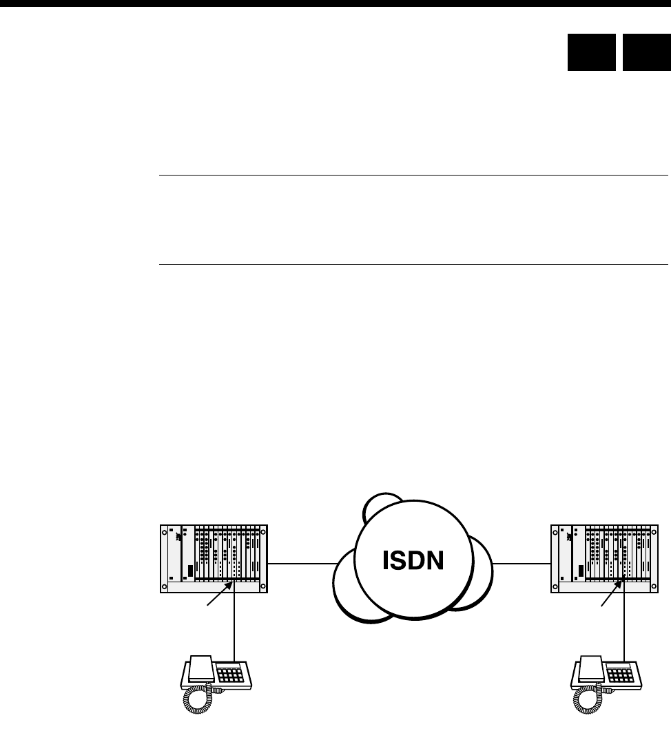
5-78 Analog line module applications
10003497.00 Rev.5
Analog line module applications
This section provides examples of using analog line modules in different scenarios.
Each example details the type of module that can be used.
Notes The ALEM and ALPM are not available in the UK.
The ALIM-EXCH module on the COMBO can be used in the same applications as those
described for the ALEM-2.
Indoor/outdoor handset extension using ALEM or ALEM-2
The figure below shows an application using the ALEM(-2) to provide extension line
circuits for direct connection of handsets. Calls may be established between handsets
through an ISDN. Either handset may initiate a call by generating a loop condition
on the two-wire interface at the ALEM(-2). Destination handset address information
is sent from the originating handset to the attached ALEM(-2) using decadic or DTMF
dial signalling. The ALEM(-2) connected to the destination handset then generates a
ring signal. When the destination handset answers the call, a bi-directional
end-to-end voice frequency path is established.
PRA PRA
ALEM or
ALEM-2 ALEM or
ALEM-2
Dials 3640111 Tel No. 3640111
RM CM
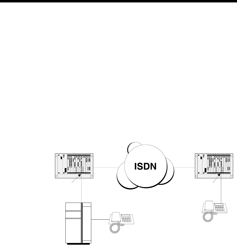
Applications 5-79
© 1993–2000 Jtec Pty Limited
Remote Extension Circuit
(ALEM, ALEM-2, ALPM, ALPM-2)
The figure below shows an example application using the ALEM(-2) to provide a
remote extension for a PABX through the ISDN. A call may be originated at the remote
extension handset by generating a loop condition on the ALEM(-2) interface. Address
information may then be forwarded to the ALEM(-2) by the originating handset using
decadic or DTMF signalling. The call is then routed through the ISDN to an ALPM(-2)
at the central PABX, which then passes the destination address information to the
PABX. The PABX alerts the destination handset, and upon handset answer, generates
a battery reversal signal to the ALPM (-2). This causes an end-to-end call path to be
established.
A call to the remote extension may also be generated by the PABX equipment. In this
case, the ring signal is generated by the PABX to the ALPM(-2). The ALPM(-2)
Hotlines a call to the remote ALEM(-2), which then generates ring signal to the remote
handset.
PRA PRA
ALEM or
ALEM-2 ALEM or
ALEM-2
Dials 3640111
Tel No. 3640111
PABX
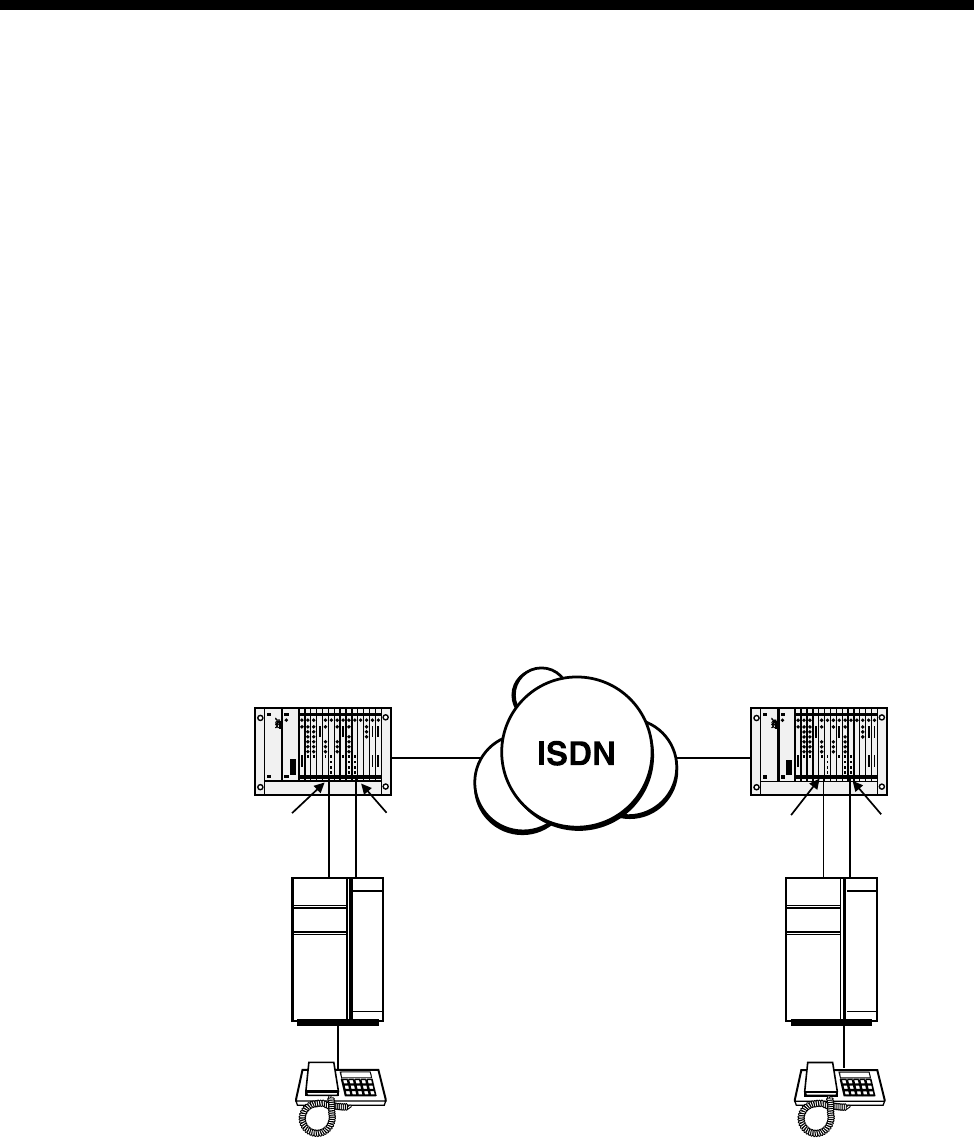
5-80 Analog line module applications
10003497.00 Rev.5
PABX-PABX Interworking
(ALEM, ALEM-2, ALPM, ALPM-2)
The figure below shows an example of PABX-PABX interworking through the ISDN.
In order for bi-directional interworking, it is necessary for a combination of ALEM(-2)
and ALPM(-2) to exist at each end of the network. Calls may be originated at either
PABX by looping a line to an ALEM(-2), and then sending decadic or DTMF address
information. The call is then routed through the ISDN to an ALPM(-2) at the
destination end, which then dials address information into the destination PABX to
cause the destination handset to be alerted. The destination PABX then indicates
destination handset answer by generating battery reversal to the ALPM(-2), which
in turn causes the ALEM(-2) to generate battery reversal to the originating PABX.
An active call may be terminated by either end. If the call is terminated at the
destination end, then the destination PABX restores battery polarity to the ALPM(-2),
which causes the ALEM(-2) to restore battery polarity to the originating PABX,
thereby indicating destination party disconnect. If the call is terminated at the
originating end, then the originating PABX generates a loop break condition to the
ALEM(-2), which then causes the ALPM(-2) to generate loop break to the destination
PABX.
PRA PRA
ALPM or
ALPM-2 ALEM or
ALEM-2
PABX
PABX
ALEM or
ALEM-2 ALPM or
ALPM-2
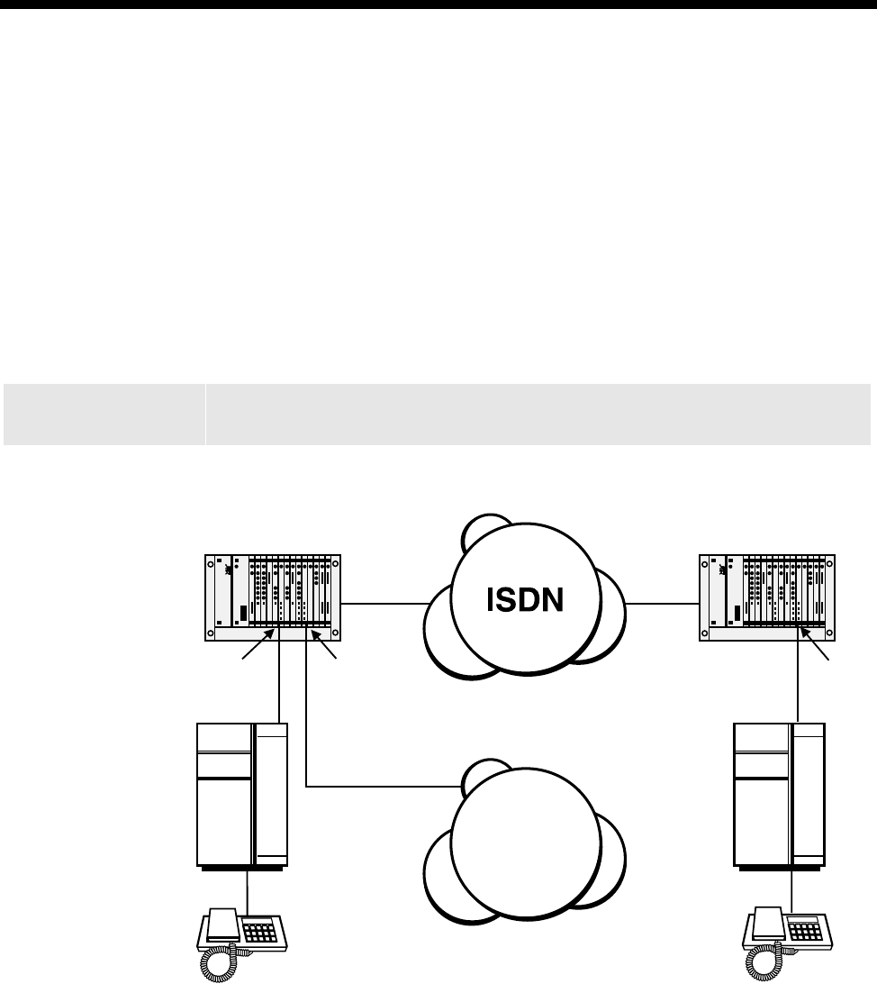
Applications 5-81
© 1993–2000 Jtec Pty Limited
PSTN Indial (Direct Dial In)
(ALEM-2)
The figure below shows an example of PSTN Indial operation. In this example, calls
may only be incoming to the ALEM-2. Destination address information is passed
from the PSTN to the ALEM-2 using decadic signalling (the ALEM-2 also supports
DTMF signalling if it is supported by the PSTN). The call may then be routed through
the node either directly or via the ISDN to an ALPM-2 connected to a destination
PABX. Upon destination handset answer, an end-to-end call path is established.
A call is terminated from the PSTN when the PSTN breaks line loop to the ALEM-2.
Warning The ALEM-2 and ALIM-EXCH are not permitted to be connected to PSTN lines in
the UK or Australia.
PRA PRA
ALPM
PABX
PABX
ALEM-2 ALPM
PSTN
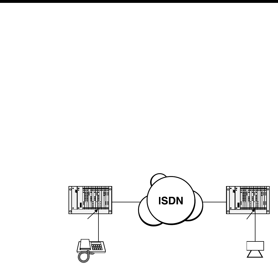
5-82 Analog line module applications
10003497.00 Rev.5
Speaker Box Application
This application uses ALEM or ALPM modules to provide a speaker box, typically
used in dealing rooms. The figure below shows how to connect the line modules to
the system.
Using ALEM or ALEM-2
In this application, the destination ALEM(-2) is configured for auto-answer mode,
which causes the ALEM(-2) to automatically answer incoming calls from the network
side without generating ring signal to the speaker box. An end-to-end voice path is
immediately established between call originating equipment and the speaker box.
Using ALPM or ALPM-2
The destination ALPM(-2) is connected to a speaker box to provide a battery feed to
its audio input line. The ALPM(-2) is configured for auto-answer mode, connect tone
mode and dial type set to DTMF. The ALPM(-2) automatically answers incoming calls
and loops the line. Two ’beeps’ precede the voice path establishment.
PRA PRA
ALEM or
ALEM-2 ALEM(-2) or
ALPM(-2)
Speaker
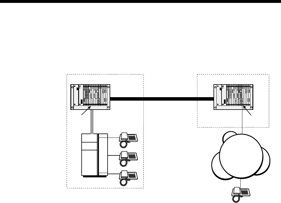
Applications 5-83
© 1993–2000 Jtec Pty Limited
Connection to PSTN Tie lines
(ALPM and ALPM-2)
The figure below shows the connection of an ALPM(-2) to a PSTN tie line.
Calls originating in the PSTN will dial the Remote Site’s PSTN number and be routed
by the PSTN to the ALPM(-2). This will present a ring signal to the ALPM(-2) that
will be carried across the ISDN to the Central Site’s PABX causing a phone to ring. In
the reverse direction, calls from the PABX are presented to the E1MN. This is then
routed through ISDN to the Remote Site causing the ALPM(-2) to dial into the PSTN
to generate ring to the remote handset.
Central site Remote site
2 Mbit/s
Tie Line
E1MN
PABX
ALPM or
ALPM-2
PSTN
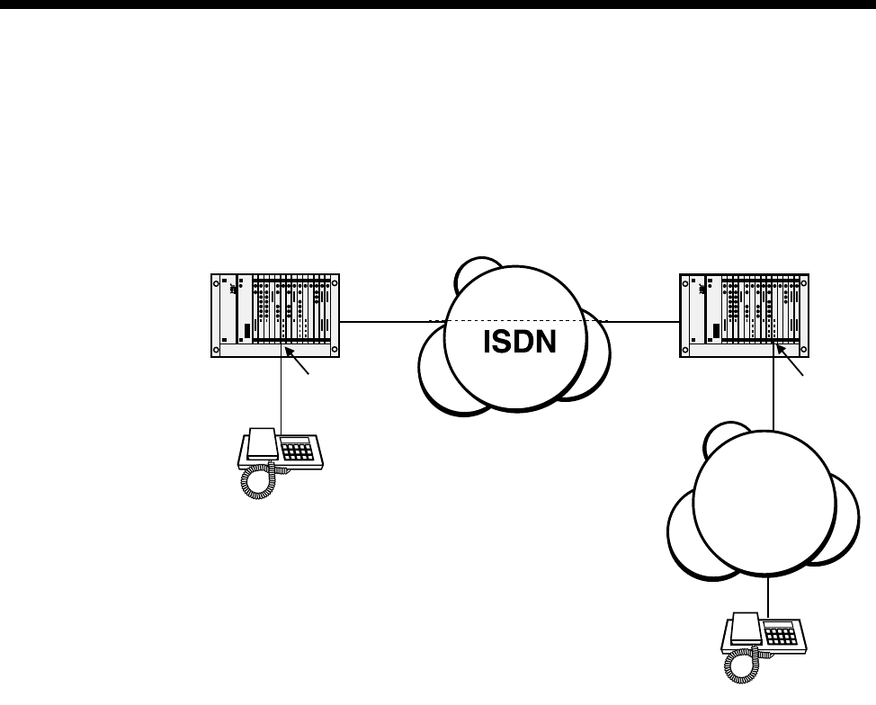
5-84 Analog line module applications
10003497.00 Rev.5
End-to-end extension circuit
(ALEM, ALEM-2, ALPM, ALPM-2)
This example shows a handset having extension access to the PSTN via an ISDN SPC.
Inband DTMF dialling is used with IDAS End-to-End mode to transfer two-wire
signalling information across the ISDN D-channel or Inband on the B-channel.
D-channel signalling
When handset ’A’ goes off hook, the ALEM(-2) sends an IDAS SETUP over the ISDN
D-channel to the remote ALPM(-2). The ALPM(-2) will auto-answer and loop the
PSTN line, thus providing a voice path for handset ’A’ to hear PSTN
tones/announcements and dial DTMF digits inband.
When handset ’B’ causes the PSTN to ring into the ALPM(-2), the ALPM(-2) sends an
IDAS SETUP over the ISDN D-channel to the remote ALEM(-2). The ALEM(-2) rings
into handset ’A’.
Disconnections can either be made by handset ’A’ or the PSTN (if it provides a call
clearing mechanism using signalling such as battery reversal or battery
disconnection).
Inband B-channel signalling
When handset ’A’ goes off-hook, the ALEM(-2) sends an IDAS SETUP over the ISDN
B-channel to the remote ALPM(-2). The ALPM(-2) will auto-answer and loop the
PSTN line, thus providing a voice path for handset ’A’ to hear PSTN
tones/announcements and dial DTMF digits inband.
PRA PRA
SPC
Handset 'A'
Handset 'B'
ALEM or
ALEM-2 ALPM or
ALPM-2
PSTN

Applications 5-85
© 1993–2000 Jtec Pty Limited
When handset ’B’ causes the PSTN to ring into the ALPM(-2), the ALPM(-2) sends an
IDAS SETUP over the ISDN B-channel to the remote ALEM(-2). The ALEM(-2) rings
into handset ’A’.
Disconnections can either be made by handset ’A’ or the PSTN (if it provides a call
clearing mechanism using signalling such as battery reversal or battery
disconnection).
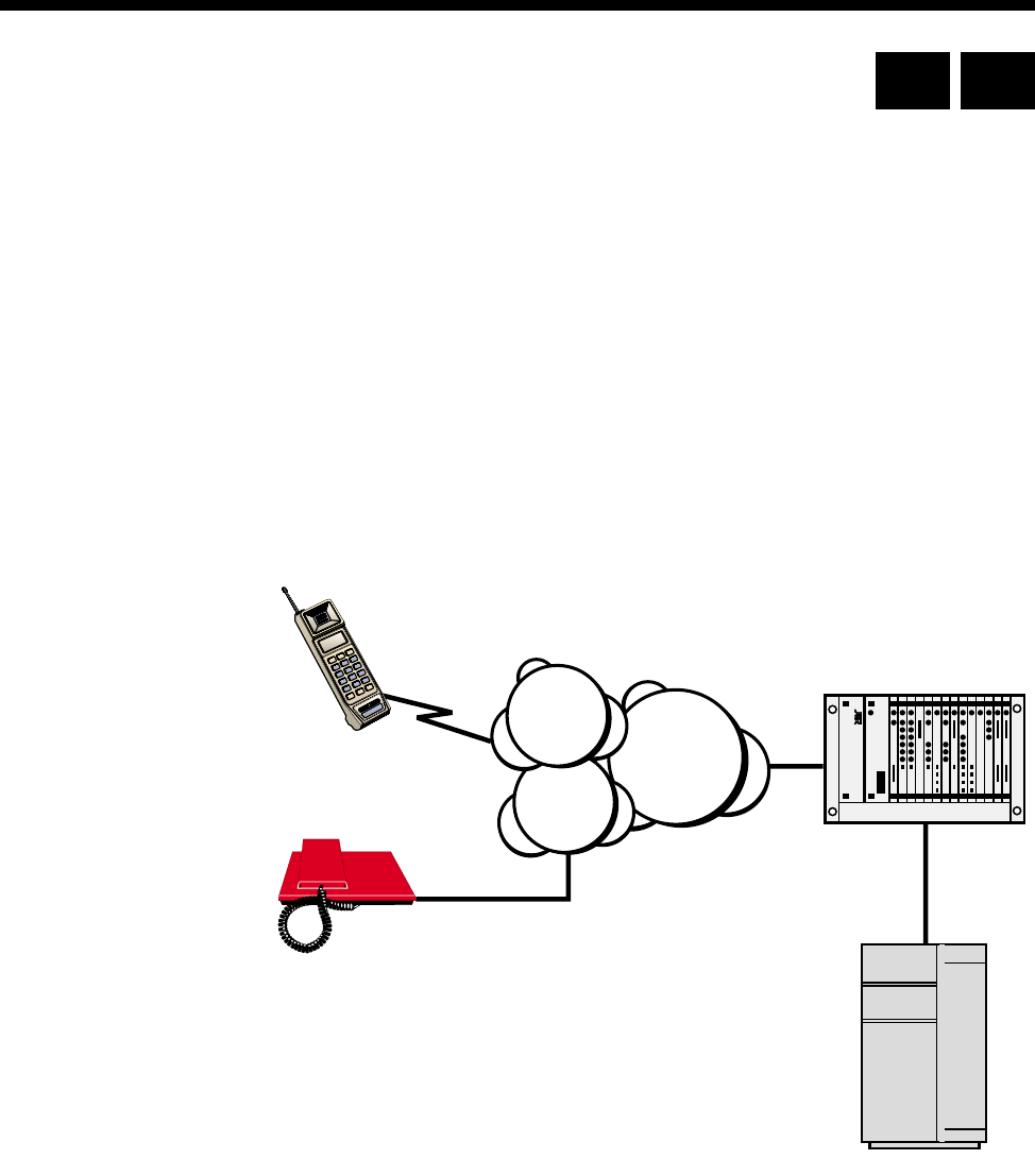
5-86 Virtual eXtension application
10003497.00 Rev.5
Virtual eXtension application
This application uses the ALPM-2 to provide remote POTS subscribers or mobile
phone users access to a central PABX as if they were an extension directly connected
to the PABX. During a call, the users have access to all the facilities offered to in-house
analog extensions of the PABX, such as call hold, call transfer, call back when free and
so on.
The Virtual eXtension feature is designed for one-to-one operation, that is, a single
PABX extension port is attached to one ALPM-2 port and is associated with one POTS
line or mobile phone.
The ALPM-2 port will always ’Hotline’ to the same number in response to a ring
applied from the PABX extension port. Equally, the POTS or mobile phone will always
call the same line number of the ALPM-2 to gain access to the PABX.
The following diagram shows a typical setup for a Virtual eXtension application:
Operation
Calls to the PABX
The remote user dials the number of the ALPM-2 line. The ALPM-2 automatically
connects the call and call charging commences. If the Access Password mode is
enabled, a sequence of four short tones is heard. The tones prompt the user to enter
the DTMF password. If the entered sequence of numbers and characters matches the
preconfigured password on the ALPM-2 line, two tones are heard as confirmation of
the correct password. The user then hears the PABX dial tone and can use the service
as normal. The ALPM-2 will disconnect the call if the password is incorrect.
If the Access Password is not enabled the user hears the PABX dial tone immediately.
Device with ALPM-2
PABX
POTS subscriber
remote user
Mobile phone
remote user ISDN
PSTN
Cellular
Network
RM CM

Applications 5-87
© 1993–2000 Jtec Pty Limited
Calls from the PABX
When the ALPM-2 detects a ring from the PABX extension port, it initiates a call to a
preconfigured ’Hotline’ number. This Hotline number matches the number of the
remote user.
The destination phone rings and, when answered, connects the call back to the
ALPM-2 which in turn applies a loop to the PABX extension port, opening the line
for a normal telephone conversation.
Configuration
The configuration of the Virtual eXtension involves the setting of up to four
parameters in the ALPM-2. These are:
•Timed Break period
•Inband DTMF digit sequence as a Timed Break Request
•Inband DTMF digit sequence as a Disconnect Request
•Inband DTMF digit sequence as an Access Password.
These parameters can be set in the ALPM-2 Line configuration dialog.
Timed Break period
A user-configured timed loop break can be applied to the analog line in response to
a user-to-user timed break (hookflash) request received from the far end of the
connection. This is an alternative to the break duration set in the user-to-user message.
To configure:
1 In the ALPM-2 line configuration dialog box, choose PABX. This opens the Virtual
eXtension Feature Control dialog box.
2 In the Use break time of n x (10ms) field enter the required break time in multiples
of 10ms. This should ideally be set to suit the PABX.
Inband DTMF digit sequence as a Timed Break Request
During a call, the remote user can apply the timed break configured above. This is
applied when the ALPM-2 detects an inband sequence of DTMF digits that match the
user-configured string. This can only be configured if you have firstly configured the
Timed Break period.
To configure the string:
1 In the ALPM-2 line configuration dialog box, choose PABX. This opens the Virtual
eXtension Feature Control dialog box.
2 In the DTMF digits to interpret as a Timed Break request field, enter up to four
digits from the range: 1, 2, 3, 4, 5, 6, 7, 8, 9, 0, *, #. These correspond to the keys on
the remote user’s telephone key pad.

5-88 Virtual eXtension application
10003497.00 Rev.5
During the call the remote user can dial the digits from the telephone key pad to
initiate the configured timed break. To ensure correct validation of the digit sequence,
the interval between dialled digits should not exceed three seconds.
Inband DTMF digit sequence as a Disconnect Request
At any time during a call, the remote user can disconnect the call by dialling a
preconfigured series of digits. When the ALPM-2 detects an inband sequence of
DTMF digits that match the user-configured string for the disconnect, the loop
applied to the analog line is removed and the ALPM-2 clears the call towards the
remote user.
To configure the string:
1 In the ALPM-2 line configuration dialog box, choose PABX. This opens the Virtual
eXtension Feature Control dialog box.
2 In the DTMF digits to interpret as a Disconnect request field, enter up to four
digits from the range: 1, 2, 3, 4, 5, 6, 7, 8, 9, 0, *, #. These correspond to the keys on
the remote user’s telephone key pad.
During the call the remote user can dial the digits from the telephone key pad to
initiate the disconnection. To ensure correct validation of the digit sequence, the
interval between dialled digits should not exceed three seconds.
Confirmation of the receipt of the valid digits is given by two tones immediately
before the call is disconnected.
Inband DTMF digit sequence as an Access Password.
It is possible that anyone knowing the number of the ALPM-2 port could dial in to
the PABX and use the facility to make unauthorised calls. This can be prevented by
configuring an Access Password.
To configure a password:
1 In the ALPM-2 line configuration dialog box enter up to eight digits in the Port
Name field. These must be from the range: 1, 2, 3, 4, 5, 6, 7, 8, 9, 0, *, #. These
correspond to the keys on the remote user’s telephone key pad.
When enabled, the password facility effectively provides a 'firewall' to the PABX. If
a remote user dials in to the ALPM-2, the password feature is indicated by a four tone
sequence. The user is then required to enter the DTMF digits that match the
configured password in the Port Name field.
The remote user must dial the sequence with no more than 12 seconds between digits.
An incorrect password results in the disconnection of the call. A correct password is
confirmed by a two tone sequence followed by the PABX dialling tone.

Applications 5-89
© 1993–2000 Jtec Pty Limited
Tips for using the Virtual eXtension feature
These tips provide advice on problems that you may encounter when using the
Virtual eXtension feature.
Identical timed break and disconnect codes
It is possible that two connected users of the Virtual eXtension feature may have
identical timed break or disconnect codes. The ALPM-2 cannot determine from which
party the inband DTMF digits originate, so it is possible for a user on the PABX side
of the call to accidentally trigger a timed break or a disconnect by dialling a specific
series of digits.
You should try to make certain that all users apply different sets of codes for each
feature. This will ensure that only the remote user can initiate a timed break or a
disconnect.
Single user per ALPM-2 port
You should ensure that only one user is allocated the ALPM-2 port number as the
ALPM-2 can only ’Hotline’ to one destination.
Recorded Voice Announcements (RVA)
PABX users calling out to a Virtual eXtension will not receive RVAs indicating that
the caller is out of range or the mobile phone is turned off. They will only hear a ring
tone until the PABX cancels the call by timing out, or when they terminate the call.
Busy called party
PABX users calling out to a Virtual eXtension that is busy will hear a ring tone until
they terminate the call or the PABX cancels it. Alternatively, they may hear a quick
burst of ring tone followed by a ’called extension disconnect’ tone. The format of the
latter tone is dependent on the PABX characteristics.
Inter-digit Timeout
There is a two second inter-digit timeout interval when entering digits for the
Disconnect and Hookflash, and a six second inter-digit timeout for the password
digits. If these timers expire the part of the string already entered is discarded, and
you will have to re-enter the whole string.
Entering the Timed Break Request
If the key for last digit of the Timed Break Request code is held down across the Timed
Break, the PABX, after the Timed Break period, detects the held-down digit as the
first digit to be dialled. For example, holding down the ’9’ of the Timed Break entry
’##89’ causes the PABX to detect and dial ’ 9’ immediately after the Timed Break. Avoid
holding keys down when entering codes.
Mobile phone voice messaging systems
If a Virtual eXtension is a mobile phone that has a voice messaging system, any
recorded voice messages will contain NU tone for a period of 30 to 90 seconds after
the caller has left the message and has hung up. As the ALPM-2 cannot detect network
tones and DTMF tones at the same time you should not use the Release on Busy Tone
option in OmniVision.
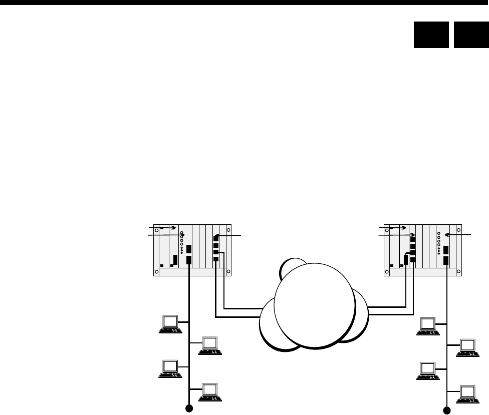
5-90 IRM applications
10003497.00 Rev.5
IRM applications
This section describes several applications for the Integrated Router Module (IRM).
For full details on the line module configuration aspects refer to page 4-215. To
configure the Router/Bridge refer to the IRM Router Configuration Manual.
Multilinking IRM to IRM
This application allows a WAN link greater than 64 kbit/s to be created without using
an BCAM-ISO. Multilinking is a facility provided by the IRM that links one logical
WAN port to multiple physical ports (see IRM Router Configuration Manual for more
details).
In this application the QBRM TEs are providing the ISDN connectivity between the
two nodes. The call LEDs on the IRM front panels indicate that all WAN ports are
active through the two Basic Rate links. The WAN throughput of 256 kbit/s is made
up of all four WAN ports running at 64 kbit/s.
RM or CM
IRM
QBRM QBRM
RM or CM IRM
ISDN
RM CM
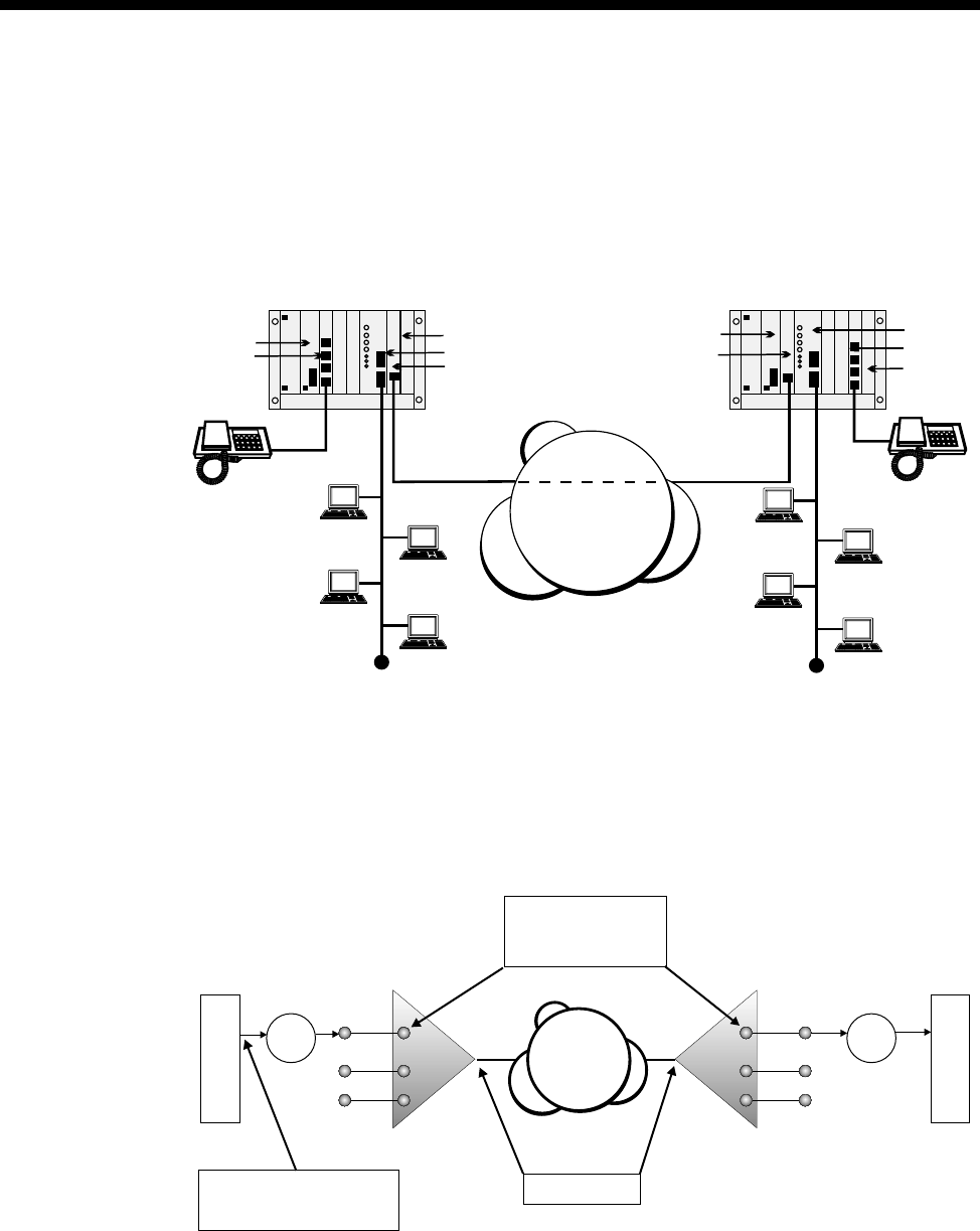
Applications 5-91
© 1993–2000 Jtec Pty Limited
Subrate primary and bandwidth on demand
This application shows an IRM running a primary WAN at a Subrate speed, for
example, 48 kbit/s. The other multi-linked WAN ports, configured to Bandwidth on
Demand (BoD) raise and clear additional 64 kbit/s calls in response to detected traffic
loads. If the primary link fails to maintain a data path, a BoD port raises a call until
the primary link is restored.
The IPMT provides the ISDN switched and SPC connectivity to the remote site. In
this setup one primary WAN port and two other BoD WAN ports are activated to
handle traffic load. A Subrate Virtual Line is configured to include both a 48 kbit/s
IRM WAN port and a compressed voice circuit on the single 64 kbit/s permanent
link. This concept is shown in the diagram below.
RM or CM
ALEM
IPM
IRM
VCM
IPM
RM or CM IRM
ALEM
VCM
ISDN
SPC
VX VX
IRM IRM
ISDN
Hotline + XSPC enabled
Fixed User Rate = 48 kbit/s
Bearer Capability to Reflect
SPC enabled
SPC enabled
Subrate Switch Data
Transparent signaling
E2E enabled
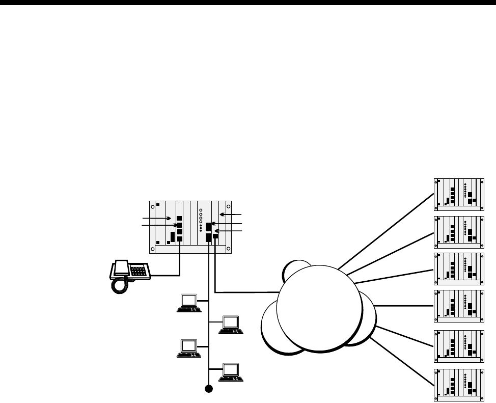
5-92 IRM applications
10003497.00 Rev.5
Linking multiple remote devices to a central site
A central site is configured as a hunt group, and expects to receive calls from any one
of a number of remote site devices. In this scenario, a given remote site always calls
the same central site. Calls are initiated by significant data (for example, Unicast
Frames generated by an IRM) and cleared after a set time due to inactivity.
When all central site WAN ports are busy, any incoming calls will receive a busy signal
until a port becomes available.
RM or CM
ALEM
IPMT
IRM
VCM
ISDN
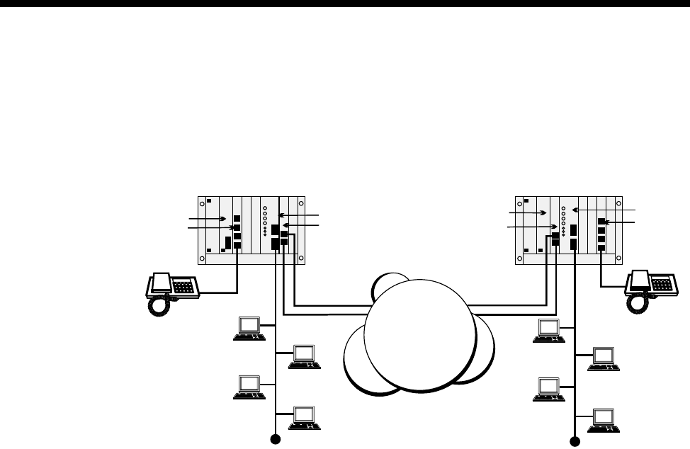
Applications 5-93
© 1993–2000 Jtec Pty Limited
Constant delay (with redundancy) — committed rate
This application shows an IRM multi-linking two dynamic, constant delay WAN
connections to provide redundancy over the network. Each DTM trunk is clocking
at 1Mbit/s and carries compressed voice as well as the IRM traffic. Each IRM WAN
port has a maximum data rate capacity of 512 kbit/s.
The DTM is configured to reserve the first two lines of each trunk for access only by
the IRM WAN ports. The remainder of the trunk capacity is available as a resource
for the other modules in the device. This means that the IRM has a ’committed’ data
rate of 128 kbit/s on each trunk. Dynamic call negotiation beyond 128 kbit/s is
dependent on channel availability. The dynamic multi-linked WANs should be
configured identically to evenly distribute the dynamic bandwidth.
In this scenario, the two multi-linked, manual call mode WAN ports are active. The
XSPC maintains the initial call, and dynamic bandwidth management controls the
speed of WAN ports, based on the detected variation in the traffic flow.
RM or CM
ALEM DTM
IRM
DTM
RM or CM IRM
ALEM
DDN
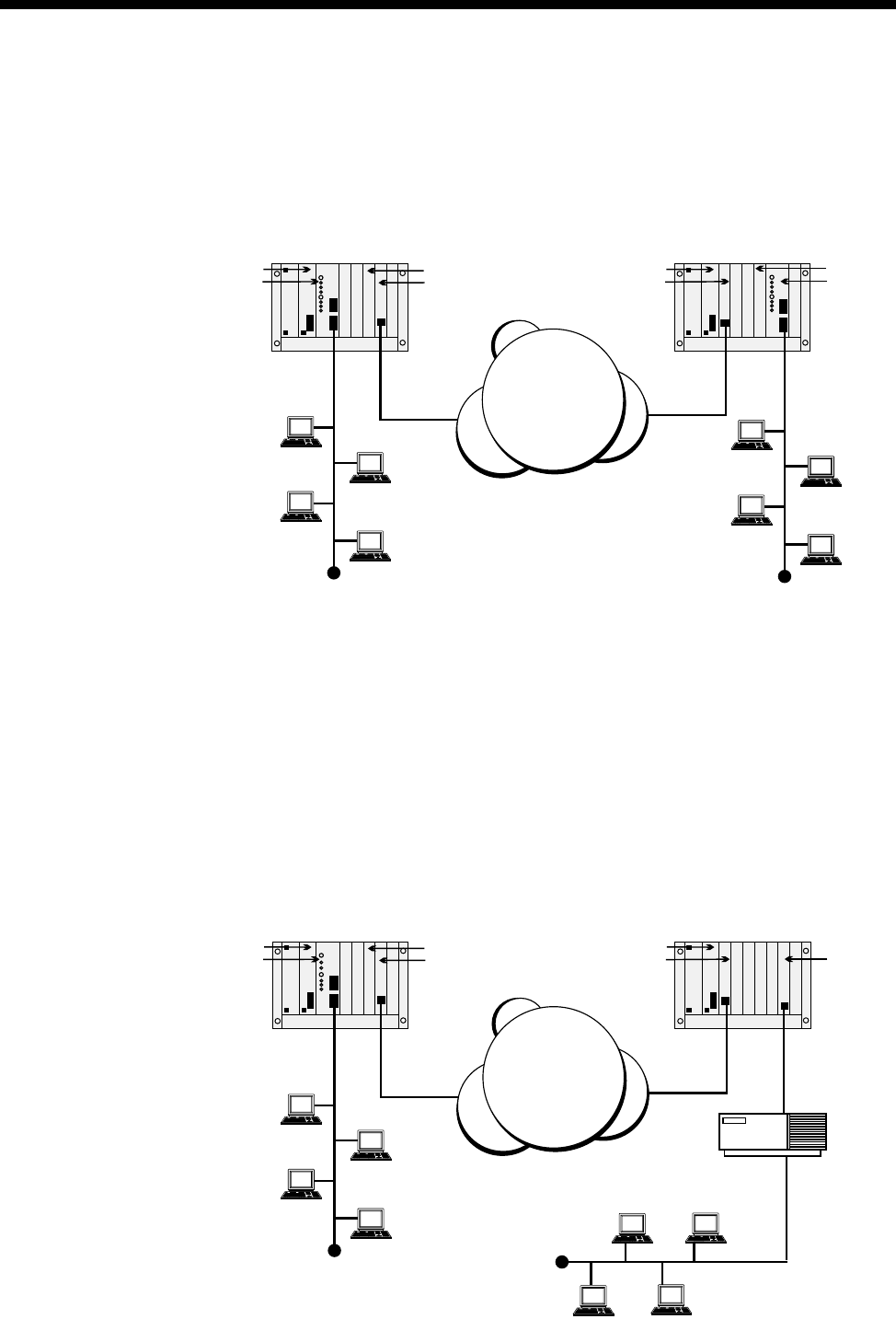
5-94 IRM applications
10003497.00 Rev.5
IRM with BCAM-ISO
Connecting LANs directly
In this application a WAN link greater that 64 kbit/s is created by using the IRM in
conjunction with an BCAM-ISO. Note that only a single Group A WAN port is needed
to obtain a WAN speed of up to 1024 kbit/s.
The IPMTs provide ISDN connectivity between the two nodes. The call LEDs on the
IRM front panels indicate that only one Group A WAN port is operating. The WAN
throughput of 1024 kbit/s is achieved by configuring the BCAM-ISO to run in Mode
1 and to connect to the IRMs on the chassis backplanes. Alternatively, Mode 3 can be
used at a speed of 960 kbit/s. In this mode the BCAM-ISO determines the quality of
the data path and can re-establish the ISDN calls if the quality is poor.
Connecting LANs via a third-party Bridge /Router
This example shows how an IRM WAN link greater that 64 kbit/s uses the BCAM-ISO
to connect to a third-party Bridge/Router using X.21. Here, only one Group A WAN
port is needed to achieve a WAN speed up to 1024 kbit/s. The remote BCAM-ISO
connects the data path to an X.21 front panel port.
RM or CM
IRM
IPMT
BCAM-ISO IPMT
RM or CM IRM
BCAM-ISO
ISDN
RM or CM
IRM
IPMT
BCAM-ISO IPMT
RM or CM
BCAM-ISO
X.21
Bridge/Router
ISDN
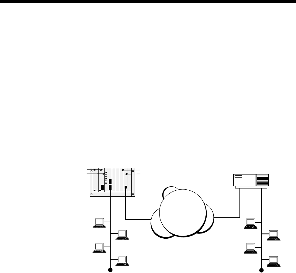
Applications 5-95
© 1993–2000 Jtec Pty Limited
The IPMTs provide ISDN connectivity between the nodes. The call LEDs on the IRM
front panels indicate that only one Group A WAN port is operating. The WAN
throughput of 1024 kbit/s is achieved by configuring the BCAM-ISO at the local site
to operate in Mode 1 and to connect to the IRM on the chassis backplane. At the remote
site, the BCAM-ISO is configured to operate in Mode 1 and to connect to the X.21
front panel port.
Alternatively, for both BCAM-ISOs, Mode 3 can be used at a speed of 960 kbit/s so
that the BCAM-ISO recognises whether the data path is of poor quality and can
re-establish the ISDN call.
Connecting LANs through a single node and a third-party Bridge/Router
This application shows how an IRM WAN link greater that 64 kbit/s uses the
BCAM-ISO to connect to a third-party Bridge/Router with an ISO standard channel
aggregation capability and an ISDN interface. Here, a single Group A WAN port is
needed to achieve a WAN speed of up to 1024 kbit/s.
The IPMT provides the ISDN connectivity to the remote Bridge/Router. The call LEDs
on the IRM front panel indicate that only one Group A WAN port is active. The WAN
throughput of 1024 kbit/s is achieved by configuring the BCAM-ISO to operate in
Mode 1 and connecting to the IRM on the chassis backplane.
Alternatively, Mode 3 can be used at a speed of 960 kbit/s so that the BCAM-ISO
recognises if the data path is of poor quality and can re-establish the ISDN calls.
RM or CM
IRM
IPMT
BCAM-ISO
PRA
Bridge/Router
ISDN
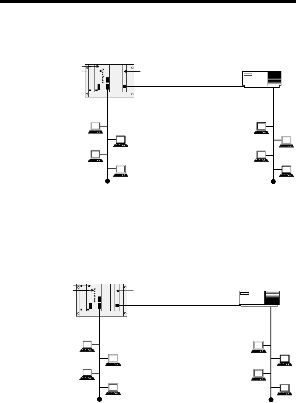
5-96 IRM applications
10003497.00 Rev.5
IRM to transparent mode BCAM-ISO
This application shows how an IRM WAN link, greater than 64kbit/s, uses the X.21
BCAM-ISO in transparent mode to connect to a third-party Bridge/Router.
Only a single Group A WAN port is needed to achieve a WAN speed up to 1.024
Mbit/s. The BCAM-ISO interconnects the data path locally to an X.21 front panel port.
When connecting to an IRM port, Manual Connect (Backplane) must be selected in
the BCAM-ISO configuration.
IRM with a High Speed Data Module (HSDM)
This application shows how an IRM WAN link, greater than 64kbit/s, uses an HSDM
to connect to a third-party Bridge/Router.
Only a single Group A WAN port is needed to achieve a WAN speed up to 1984 kbit/s.
The HSDM interconnects the data path locally to an X.21 front panel port.
RM or CM
IRM
BCAM-ISO
X.21
Bridge/Router
RM
IRM
HSDM
X.21
Bridge/Router
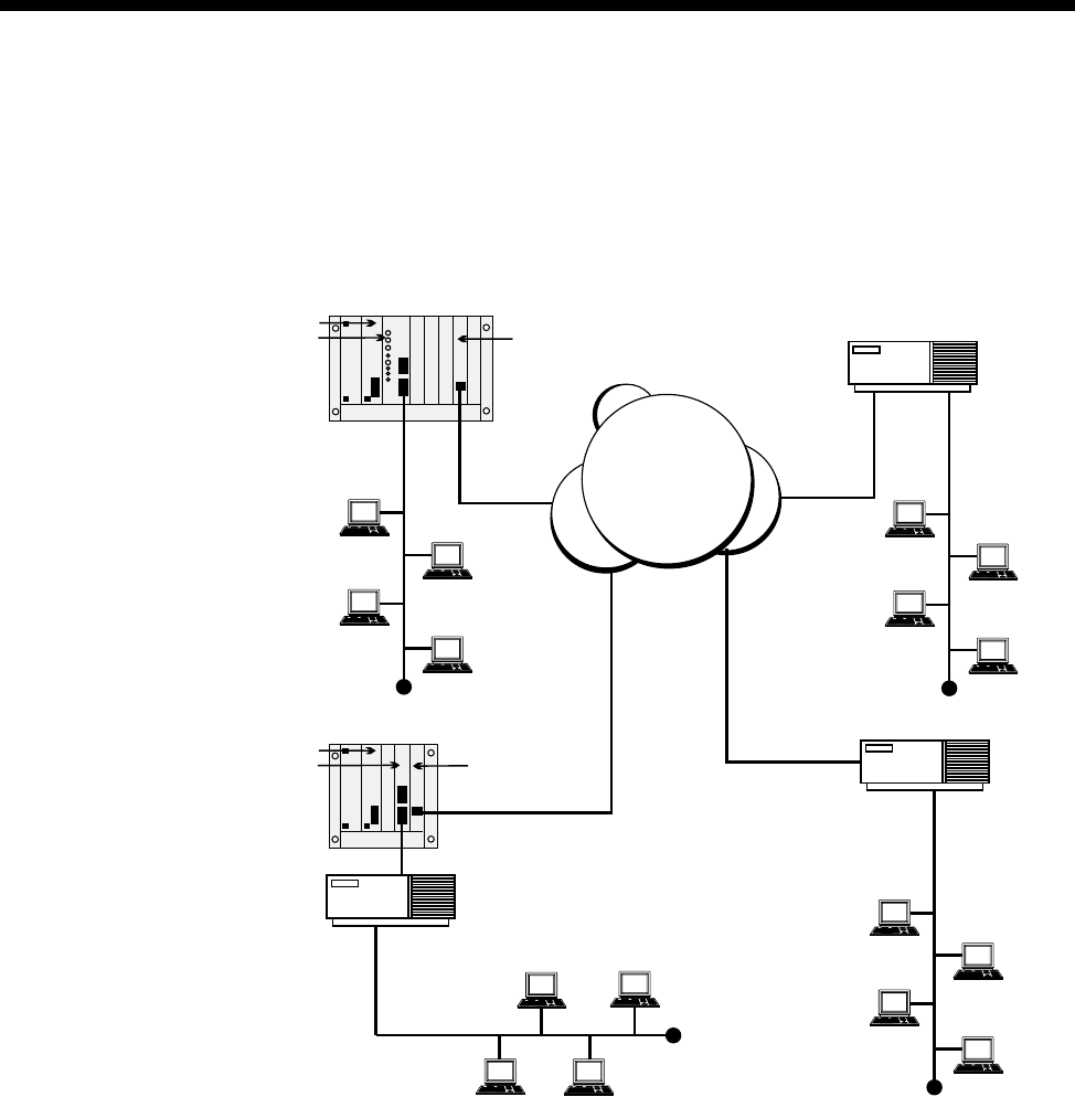
Applications 5-97
© 1993–2000 Jtec Pty Limited
IRM with a Digital Line module (DLM)
This application shows how a central site can use the IRM WAN links at 64 kbit/s
and less using a DLM to connect to a V.35 third-party Bridge/Router through ISDN.
Only one WAN port is connected to the remote V.35 SDLM. The other two are
connected to the ISDN third-party Bridge/Routers.
The IPMT provides the ISDN connectivity to the remote sites. The call LEDs on the
IRM front panel indicate that three WAN ports are active. The central IRM routes
traffic to all remote networks and provides a common central node.
RM or CM
IRM
IPMT
BRA
BRA
Bridge/Router
Bridge/Router
Bridge/Router
V.35
ISDN
RM or CM
SDLM BRM
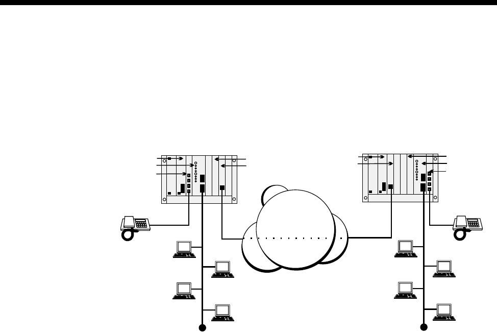
5-98 IRM applications
10003497.00 Rev.5
Subrate IRM and compressed voice
This application uses Subrate multiplexing and voice compression together with
IRMs running at Subrate speeds (for example, 32kbit/s). Only one IRM WAN port is
used with a compressed voice circuit. The principles shown in the previous
applications that use non-aggregated case are still valid.
The IPMT provides the ISDN SPC (or XSPC) connectivity to the remote site. The call
LEDs on the IRM front panels indicate that one WAN port is active. A Subrate Virtual
Line is configured to include both a 32 kbit/s IRM WAN port and a compressed voice
circuit on the one 64 kbit/s permanent link.
RM or CM
IRM
ALEM
IPMT
VCM IPMT
RM or CM
IRM
ALEM
VCM
ISDN
SPC

Applications 5-99
© 1993–2000 Jtec Pty Limited
Dial Gateway application
The Dial Gateway is a solution that provides for remote dial-up TCP/IP applications
such as Internet and Intranet. The Dial Gateway satisfies a variety of remote access
needs including telecommuting, remote office, and Internet/Intranet access.
The system provides the power of remote access to a wide range of equipment
including:
•analog PSTN modems
•GSM mobiles
•ISDN PC cards or terminal adaptors
•remote LANs via routers.
The Dial Gateway supports 30 remote users who are accessing the system using PSTN
modems or ISDN digital connections. It can be expanded to provide support for up
to 120 remote users including up to 90 analog PSTN users. The amount of expansion
depends on slot availability and the configuration of the system.
The Dial Gateway includes an ISDN interface for connecting to the carrier's ISDN
(IPMT), a 32 port TCP/IP router supporting PPP and Frame Relay WAN protocols
(FSM), 30 digital modems (DMM), plus a Network Management System such as
OmniVision.
This diagram below shows a typical Dial Gateway application.
ISDN
PSTN
Frame
Relay
Network
Management
System
RADIUS Server
Dial Gateway
Router
07 32608000
5 x Numbered WAN Link Sites
Calling 07 3260 8010
10 x Unnumbered WAN Link Sites
Calling 07 3260 8020
RM CM

5-100 Dial Gateway application
10003497.00 Rev.5
Configuring the Dial Gateway
Note The following information assumes that you are familiar with the modules that make
up the Dial Gateway package (IPMT, FSM, DMM and respective PSM).
The following steps are typical of those necessary to connect and configure a Dial
Gateway,
1 Connect the Dial Gateway to the power source. Refer to the Installation Manual for
details.
2 Connect the following interfaces:
The ISDN Primary Rate Module (IPMT) to the ISDN Primary rate NT1 provided
by your carrier.
The 10BaseT port of the Frame Switch Module (FSM) to the Ethernet hub.
You can optionally connect the high speed Frame Relay port on the front panel of
the FSM to the Frame Relay NTU provided by your carrier. This port can provide
a high speed (up to 2Mbit/s) connection to the Internet backbone provided by
your carrier. Alternatively it can be connected to an upstream ISP’s router.
See the respective chapters in the Installation Manual for further details.
3 Install the network management system. See the OmniVision User Manual for
details.
4 Configure the IPMT:
Enter the Group Number and Area code given by your ISDN provider. See IPMT
configuration on page 4-3 for further details.
5 Configure the FSM Ethernet port:
Enter an IP Address. See FSM configuration on page 4-227 for further details.
6 Configure the FSM WAN ports:
Enter an IP Address for each WAN port. See FSM IP addressing and Routing on page
4-229 for details.
Set up Authentication if required. See Login and Authentication on page 4-233 for
details.
Note We recommend that you keep similarly configured ports contiguous. For example,
you may set WAN ports 1 to 5 as unnumbered ports using CHAP authentication, ports 6 to
10 as numbered ports using text login authentication, and ports 11 to 30 as unnumbered ports
using PAP authentication. Keeping similarly configured ports in groups aids call routing and
troubleshooting.
7 Configure RADIUS. See RADIUS on page 4-232 for details.

Applications 5-101
© 1993–2000 Jtec Pty Limited
8 Configure Call Routing.
The simplest method for configuring call routing is to create Linesets which direct
calls to the appropriate FSM ports. Linesets provide the ability to have multiple
WAN ports exist as a rotary group for a single number. We recommend that you
group similarly configured ports in a single lineset. For example, Unnumbered
ports running CHAP would all exist in a single lineset while Numbered ports
running CHAP would be members of a different lineset. See Linesets on page 3-17
for details.
Note If there are no DMM modem resources free, calls are not answered. In this instance,
the calls are rejected with cause ’User Busy’. This avoids a flag-fall charge.
After these basic steps, the Dial Gateway is ready for use.
Example configuration
The following information summarises the configuration and provides the various
entries to configure the typical network shown on page 5-99.
ISDN service
The ISDN Primary Rate Interface supplied by the ISDN provider has the group
number 07 3260 8000 and includes a 100 number range.
Group Number 07 3260 8000
Number Range 07 3260 8000 - 07 3260 8099
The IPMT should be configured with a Group Number of 3260 8000 and the National
Significant Area Code is 7.
WAN links
The example shows a mixture of Numbered and Unnumbered WAN link sites. We
recommend that you group similarly configured ports in a single lineset. For example,
the Unnumbered WAN link sites would call a different number and be routed by a
single lineset while the Numbered WAN link sites would each need to call an
individual number (so that remote and local WAN IP addresses correspond). Linesets
should still be used to configure the Numbered WAN links because it provides a
single configuration point for all.
In this example, a number within the PRA number range has been chosen for each of
the Numbered WAN links to call, while a single number has been selected for the
Unnumbered WAN links.

5-102 Dial Gateway application
10003497.00 Rev.5
Numbered WAN Links
Port # 1 = 3260 8011
Port # 2 = 3260 8012
Port # 3 = 3260 8013
Port # 4 = 3260 8014
Port # 5 = 3260 8015
Unnumbered WAN Links:
Ports # 6 to 15 = 3260 8020
Configure Linesets
Numbered WAN Links Linesets
Port Parameter Setting
Port 1 Minimum number 32608011
Maximum number 32608011
Member of lineset fsm line 1
Attributes for destination type Local
Port 2 Minimum number 32608012
Maximum number 32608012
Member lines fsm line 2
Attributes for destination type Local
Port 3 Minimum number 32608013
Maximum number 32608013
Member lines fsm line 3
Attributes for destination type Local
Port 4 Minimum number 32608014
Maximum number 32608014
Member lines fsm line 4
Attributes for destination type Local
Port 5 Minimum number 32608015
Maximum number 32608015
Member lines fsm line 5
Attributes for destination type Local

Applications 5-103
© 1993–2000 Jtec Pty Limited
Unnumbered WAN Links Lineset
Ports Parameter Setting
Ports 6 to 15 Minimum number 32608020
Maximum number 32608020
Member lines fsm line 6
fsm line 7
fsm line 8
fsm line 9
fsm line 10
fsm line 11
fsm line 12
fsm line 13
fsm line 14
fsm line 15
Attributes for destination types Local

5-104 Channel Bank application
10003497.00 Rev.5
Channel Bank application
Overview
Channel Banks are devices that provide connectivity between analog telephone
interfaces, and G.703/G.704 E1 and T1 interfaces. They provide internal mapping of
an analog interface to a channel of either an E1 or T1 digital interface. This may be
with or without their various signalling capabilities. The E1 and T1 interfaces operate
in Channel Associated Signalling (CAS) or Robbed Bit Signalling (RBS) modes,
respectively.
This section only deals with Channel Banks that provide point-to-point connections
to other Channel Banks over a typical core network. The Channel Bank (CB) analog
interfaces described here support three modes of connection across a variety of 2-wire
and 4-wire interfaces. The connection modes are:
•Automatic Ring Down (ARD)
•Manual Ring Down (MRD)
•Tone Only (TO)
Automatic Ring Down (ARD)
ARD is a basic ring-out/loop-in 2-wire battery interface. The circuit operates in a
similar way to a Hotline call. The far end Channel Bank provides ring tone to the near
end. Communication is via telephone handset or microphone-headset.
Manual Ring Down (MRD)
MRD is either a 2-wire or a 4-wire 600Ω dry interface for speech transfer and
signalling. The speech path is open for two-way communication at all times, except
when signalling occurs. The term 'GEN-GEN interface' is often used for this type of
connection. The alerting device, at the near end, is activated locally during the
application of the calling signal to the far end. Communication is often through a
personal loudspeaker. However, multiple personal loudspeakers, public
loudspeakers, a telephone handset or a microphone-headset may also be used.
Tone Only (TO)
TO is either a 2-wire or a 4-wire 600Ω dry interface for speech transfer. No signalling
is provided. The speech path is open for two-way communication at all times. TO is
effectively MRD without the signalling. Communication is usually through a public
loudspeaker, although a single personal loudspeaker or multiple personal
loudspeakers may also be used.
RM CM

Applications 5-105
© 1993–2000 Jtec Pty Limited
Types of Channel Banks
This section deals with three known types of Channel Bank:
•N.E.T. ADNX (T1 interface)
•Telco Systems Channel Bank (T1 interface)
•Craycom Channel Bank (E1 interface).
There are three point-to-point combinations for each of the ARD, MRD and TO
circuits:
•Channel Bank (E1) to Channel Bank (E1)
•Channel Bank (T1) to Channel Bank (T1)
•Channel Bank (E1) to Channel Bank (T1).
The signalling provided by the analog interfaces is converted to AB bit signalling for
transport via the T1/E1 digital network.
Note The core network must provide signalling mapping between T1 and E1 interfaces.
ARD Channel Bank Signalling
The signalling states for ARD are IDLE, SEIZE, ALERTING, ANSWER, CLEAR
FORWARD, CLEAR BACKWARD. Only two signals are used to represent the state:
•On-hook Signal
•Off-hook Signal.
ADNX and Telco
The ADNX (T1) and Telco Systems (T1) Channel Banks use the following RBS AB bit
states for ARD connections:
•On-hook Signal: AB = 11
•Off-hook Signal: AB = 00
Only the input A bit is evaluated for signal change. This signalling is called PLAR
(Private Line Automatic Ring-down).
Craycom
The Craycom (E1) Channel Bank uses the following CAS AB bit states for ARD
connections:
•On-hook Signal: AB = 11
•Off-hook Signal: AB = 01
Only the input A bit is evaluated for signal change. This signalling is called SSDC5A.

5-106 Channel Bank application
10003497.00 Rev.5
MRD Channel Bank Signalling
The signalling states for MRD are RING OFF and RING ON. The two signals used
to represent the state are the ring-off signal and the ring-on signal.
ADNX and Telco
The ADNX (T1) and Telco Systems (T1) Channel Banks use the following RBS AB bit
states for MRD connections:
•On-hook Signal: AB = 00
•Off-hook Signal: AB = 11
Only the input A bit is evaluated for signal change. This signalling is called E&M.
Craycom
The Craycom (E1) Channel Bank uses the following CAS AB bit states for MRD
connections:
•On-hook Signal: AB = 11
•Off-hook Signal: AB = 01
Only the input A bit is evaluated for signal change. This signalling is called SSDC5A.
Channel Bank Emulation
ARD support
This equipment supports ARD via an on-demand Hotline connection between an
ALEM Line and a T1M Line or between an ALEM Line and an E1M Line. Hotline
operation allows ring tone to be supplied to the near end caller when the device is
acting as the far end.
MRD support
This equipment supports MRD via a UDAS protocol, XSPC Hotline between an EMM
Line and a T1M Line, or between an EMM Line and an E1M Line. An external adapter
converts between the 4-wire E&M interface of the EMM and 2-wire 'GEN-GEN
interfaces'. Use of the UDAS protocol allows accurate transfer of the user-controlled
ring cadence between the two ends.
TO support
This equipment supports TO via a permanent manual connection between an EMM
Line and either a T1M Line or an E1M Line. An external hybrid is used to convert
the 4-wire speech interface provided by the EMM to a 2-wire interface. The E and M
leads of the EMM are not connected. Manual connections provide permanent,
two-way voice paths and disregard any spurious signals that occur on the signalling
input lead of the EMM ports.

Applications 5-107
© 1993–2000 Jtec Pty Limited
Note Both Channel Banks and our equipment use a variety of signalling to provide ARD
and MRD connections over T1 and E1 interfaces. Mapping of the signalling, to provide
compatibility, must be performed in the core network.
For more detailed information on E1 and T1 signalling associated with Channel
Banks, refer to Appendix O.
Configuring the equipment for a Channel Bank application
This section details the configuration for each module used in a particular Channel
Bank scheme.
Module capabilities
The T1M supports any combination of ARD, MRD and TO circuits, on a
channel-by-channel basis.
The E1M supports a combination of ARD and TO circuits, on a channel-by-channel
basis, from a given module. It also supports a combination of MRD and TO circuits,
on a channel-by-channel basis, from a given module. However, it does not support
both ARD and MRD circuits on the same module.
Call establishment method
This equipment emulates a Channel Bank by using general switching functions and
specific signalling features:
•ARD connections are established between ALEM and T1M/E1M Line pairs as
on-demand Hotline connections.
•MRD connections are established between EMM and T1M/E1M Line pairs as
XSPC Hotline connections.
Note Line pairs in this context are defined by configuring two Lines to Hotline to each other.
This requires the allocation and configuration of a numbering plan in each device. A
numbering plan of three digits or more will be adequate for this purpose. However,
a 7-digit number will minimise confusion and simplify configuration. For example,
a plan with the number range 5550100 through 5551599 could be used. Using this
plan, Line numbers are allocated according to module card slot number and port or
channel number.
Note Line numbers are not permitted to have zero as the first digit. Only Linesets can
accommodate numbers commencing with zero.

5-108 Channel Bank application
10003497.00 Rev.5
Module placement
For ease of configuration and to maintain symmetry, we recommend that you follow
these general rules:
•Install the CM or RM in slot 15
•Install ALEMs and EMMs in slots 14 and down
•Install T1Ms and E1Ms in slots 1 and up.
This module arrangement ensures the efficient use of the backplane TDM channel
allocation. It also provides a convenient system for allocating numbers. For example,
the Line number of the third port of an ALEM in slot 12 becomes 5551203 and the
Line number of the 17th channel of a T1M in slot 5 becomes 5550517.
Speech encoding
Encoding and decoding of analog speech to digital format is performed in codecs on
the ALEM and EMM modules. Both modules support µ-law or A-law encoding on
per-port basis. The coding used by a given port is selected during the Line
configuration.
Note The core network must provide µ-law/A-law conversion where necessary.
Supervisory Tones
Supervisory tones, that is, Ring Tone, Fast Busy Tone and so on, are generated on the
Control Module or Resource Manager. The tones are generated by a Tone ROM on
the CM and via software on the RM. The tones generated vary according to country
and market requirements, providing different cadences with either µ-law or A-law
encoding.
Refer to the Installation Manual for information on each country variant for the CM
Tone ROM.
Note It is important that the CM is fitted with the correct Tone ROM for the target listener.
Ensure the correct Tone ROM is fitted whenever changing a CM. The RM is capable of
generating all tones without the need to change hardware.
Configuring the system parameters
The following are the minimum requirements necessary to ensure functional
operation of a stand-alone device for Channel Bank operation.
Configure the CM or RM Configuration parameters
1 Enter a Manager Access Number. (e.g. 5551598)
2 Enter a Test Line Number. (e.g. 5551599)

Applications 5-109
© 1993–2000 Jtec Pty Limited
3 Configure the Signalling Access (CM-SAM/RM-SAM), Inband Signalling
Router Table and Enable Default use D channel.
Configure the VX Configuration parameters:
1 Enter a Minimum Number and Maximum Number. (e.g. Min = 5550100, Max =
5551599). Do not enter an Area Code.
Confirm Country Code settings
1 Select Version Display from the Device menu.
2 Confirm that the correct Country Codes are set for your application.
Automatic Ring Down (ARD) parameters
The following are the minimum requirements necessary to ensure functional
operation of a stand-alone device for ARD Channel Bank operation.
T1M (ARD)
Configure the T1M Card Control parameters:
1 Set Framing and Zero Suppression as appropriate for the connected equipment.
Configure the Line Configuration parameters for each T1M Line (channel) operating
as an ARD circuit. The following parameters are the exceptions to the module’s
default configuration:
1 Enter a Line Number.
2 In Bearer Capability
•Set Octet 3 Transfer to Speech
•Enable Octet 5 and set to µ-law.
3 In Call Establishment Modes:
•Enter a Hotline Number (the same as the Line Number of the paired ALEM
port).
•Enable Hotline
•Disable DDI (Indial)
4 Set Protocol to PLAR.

5-110 Channel Bank application
10003497.00 Rev.5
E1M (ARD)
Note ARD operation is an entire module setting, and not a Line-by-Line setting. Individual
E1M channels cannot be configured for MRD operation when the module is configured for
ARD operation. However, individual channels can be configured for TO operation when the
module is configured for ARD operation.
Configure the E1M Card Control parameters:
1 Enable CAS enable.
2 Set CRC enable as appropriate for the connected equipment.
3 Set Protocol to ARD.
Configure the Line Configuration parameters, for each E1M Line (channel) operating
as an ARD circuit. The following parameters are the exceptions to the module’s
default configuration:
1 Enter a Line Number.
2 In Bearer Capability:
•Set Octet 3 Transfer to Speech
•Enable Octet 5 and set to A-law
3 In Call Establishment Modes:
•Enter a Hotline Number (make the same as the Line Number of the paired
ALEM port).
•Enable Hotline
•Disable DDI (Indial).

Applications 5-111
© 1993–2000 Jtec Pty Limited
ALEM (ARD)
Configure the Line Configuration parameters, for each ALEM Line (port) operating
as an ARD circuit. The following parameters are the exceptions to the module’s
default configuration.
Note Prior to configuration, set the required physical port impedance for each port by
setting the appropriate links on the ALEM circuit board. Refer to the Installation Manual
for instructions.
1 Enter a Line Number.
2 In Bearer Capability:
•Set Octet 3 Transfer to Speech
•Enable Octet 5 and set to µ-law if paired with a T1M or to A-law if paired
with an E1M.
3 In Low Layer Compatibility:
•Set Octet 3 Transfer to Speech
•Enable Octet 5 and set to µ-law if paired with a T1M or to A-law if paired
with an E1M
4 In Call Establishment Modes:
•Enter a Hotline Number (the same as the Line Number of the paired
T1M/E1M channel).
•Enable Hotline.
5 In Codec, Relative Levels:
•Set Digital → Analog and Digital ← Analog, to values appropriate for the
installation.
6 In Signals:
•Set Signalling Options to Ring Out / Loop In.

5-112 Channel Bank application
10003497.00 Rev.5
Manual Ring Down (MRD) Parameters
The following are the minimum requirements necessary to ensure functional
operation of a stand-alone device for MRD Channel Bank operation.
T1M (MRD)
Configure the T1M Card Control parameters:
1 Set Framing and Zero Suppression as appropriate for the connected equipment.
Configure the Line Configuration parameters, for each T1M Line (channel) operating
as an MRD circuit. The following parameters are the exceptions to the module’s
default configuration:
1 Enter a Line Number.
2 In Bearer Capability confirm these settings:
•Set Octet 3 Transfer to Unrest. Digital
•Disable Octet 5.
3 In Call Establishment Modes:
•Enter a Hotline Number (the same as the Line Number of the paired EMM
port).
•Enable Hotline
•Enable XSPC
•Disable DDI (Indial)
•Enable End-to-End.
4 Set Protocol to E&M Immediate Start.

Applications 5-113
© 1993–2000 Jtec Pty Limited
E1M (MRD)
Note MRD operation is an entire module setting for the E1M and not Line-by-Line.
Individual E1M channels cannot be configured for ARD operation when the module is
configured for MRD operation. However, individual channels can be configured for TO
operation when the module is configured for MRD operation.
Configure the E1M Card Control parameters.
1 Enable CAS enable.
2 Enable OPS mode.
3 Set the CRC enable as appropriate for the connected equipment.
4 Set Protocol to MRD.
Configure the Line Configuration parameters, for each E1M Line (channel) operating
as an MRD circuit. The following parameters are the exceptions to the module’s
default configuration.
1 Enter a Line Number.
2 In Bearer Capability:
•Set Octet 3 Transfer to Unrest. Digital.
•Disable Octet 5.
3 In Call Establishment Modes:
•Enter a Hotline Number (the same as the Line Number of the paired EMM
port).
•Enable Hotline
•Enable XSPC
•Disable DDI (Indial)
•Enable End-to-End.

5-114 Channel Bank application
10003497.00 Rev.5
EMM (MRD)
Configure the Line Configuration parameters, for each EMM Line (port) operating
as an MRD circuit. The following parameters are the exceptions to the module’s
default configuration.
1 Enter a Line Number.
2 In Bearer Capability:
•Set Octet 3 Transfer to Unrest. Digital
•Disable Octet 5.
3 In Low Layer Compatibility:
•Set Octet 3 Transfer to Speech
•Enable Octet 5 and set to µ-law if paired with a T1M or to A-law if paired
with an E1M.
4 In Call Establishment Modes:
•Enter a Hotline Number (the same as the Line Number of the paired
T1M/E1M channel).
•Enable Hotline
•Disable DDI (Indial)
•Disable Back Busy
•Enable End-to-End
•Enabled Unack
•Disable Auto Answer.
5 In Codec, Relative Levels:
•Set Digital → Analog and Digital ← Analog to values appropriate for the
installation.

Applications 5-115
© 1993–2000 Jtec Pty Limited
Tone Only (TO) Parameters
The following are the minimum requirements necessary to ensure functional
operation of a stand-alone device for Channel Bank operation.
T1M (TO)
Configure the T1M Card Control parameters:
1 Set Framing and Zero Suppression as appropriate for the connected equipment.
Configure the Line Configuration parameters, for each T1M Line (channel) operating
as a TO circuit. The following parameters are the exceptions to the module’s default
configuration.
1 Set Protocol to None.
2 In Call Establishment Modes:
•Set Subrate virtual member or manually connected to Yes.
E1M (TO)
Configure the E1M Card Control parameters for either ARD or MRD module
operation.
Configure the Line Configuration parameters, for each E1M Line (channel) operating
as a TO circuit. The following parameters are the exceptions to module’s default
configuration.
1 In Call Establishment Modes:
•Set Subrate virtual member or manually connected to Yes.
EMM (TO)
Configure the Line Configuration parameters, for each EMM Line (port) operating
as an TO circuit. The following parameters are the exceptions to module’s default
configuration.
1 Enable End-to-End.
2 Set Subrate virtual Line member or manually connected to Yes.
3 In Bearer Capability:
•Set Octet 3 Transfer to Speech
•Enable Octet 5 and set to µ-law if paired with a T1M or to A-law if paired
with an E1M.

5-116 Channel Bank application
10003497.00 Rev.5
4 In Low Layer Compatibility:
•Set Octet 3 Transfer to Speech
•Enable Octet 5 and set to µ-law if paired with a T1M or to A-law if paired
with an E1M
5 In Codec, Relative Levels:
•Set Digital → Analog and Digital ← Analog to values appropriate for the
installation.
Establishing ARD Connections
The connections between ARD Line pairs are temporary. They are established in
response to SEIZE from the analog equipment attached to the ALEM or from the CB
equipment attached to the T1M/E1M. When both the analog equipment and the CB
equipment return to idle, the connection between the ARD Line pairs is cleared down.
This type of connection is known as an 'on-demand' call. Our equipment provides
supervisory tones, such as Ring Tone to Lines (channel/ports) establishing
connections as on-demand calls.
Establishing MRD Connections
The connections between MRD Line pairs are established as permanent connections.
Once established, signalling transfers between the EMM port and the T1M/E1M
channel and a two-way speech path is open.
To establish the connection, enable the XSPC checkbox control for the T1M or E1M
Line as shown in the configuration details above.
A connection between the Line pairs will automatically establish within 20 seconds.
This can be monitored using OmniVision port status display on the EMM Port and
T1M/E1M Channel. In both cases, the colour changes from blue to yellow on
successful establishment of the connection.
The XSPC connection between the Line pairs remains established, irrespective of T1M
or E1M link conditions. The connection will also automatically re-establish after CM
initialisation or restoration of power following an outage.

Applications 5-117
© 1993–2000 Jtec Pty Limited
Establishing TO Connections
The connections between TO Line pairs are established as permanent connections.
On establishment, a two-way speech path is open.
The TO connection is a ’Manual Connection’. To establish a Manual Connection
between TO Line pairs, follow the instructions provided below:
1 Establish an on-line session with the device.
2 Select Connection Manager Control from the Other menu.
3 Select Bidirectional.
4 Enable Non-Volatile.
5 Select External.
6 Scroll through the entries in the This Connection table and select an EMM port
entry.
7 Select the From button (or double-click on the EMM port entry). The Line
information, from the selected entry appears in Card, Sub and Line fields beside
the From button.
8 Scroll through the entries in the This Connection table again and select a T1M or
E1M channel entry.
9 Select the To button (or double-click on the T1M/E1M channel entry). The Line
information from selected entry appears in the Card, Sub and Line fields beside
the To button.
10 If you used the double-click method, go to step 12.
11 Select the Connect button.
12 A new entry appears in the Active Connections table.
Note The From and To Line information fields become blank.
13 Verify that the Line information parts of the new listing match the required EMM
and T1M/E1M pairs.
14 Repeat steps 4 - 12 for all required TO connections.
15 Press the OK button when you have finished installing connections. This closes
the dialog.
16 Verify that the appropriate EMM ports and the T1M/E1M channel indicators have
changed colour from blue to green.

5-118 Channel Bank application
10003497.00 Rev.5

Appendices 6-1
© 1993–2000 Jtec Pty Limited
6Appendices

6-2 Appendix A
10003497.00 Rev.5
Appendix A
Data rates for Subrate multiplexing
User data rate
(kbit/s) Sync Async Subchannel rate
with V.110 Subchannel rate
without V.110
64 Yes No —64 kbit/s
56 Yes No 64 kbit/s 56 kbit/s
48 Yes No —64 kbit/s
24 Yes No —24 kbit/s
19.2 Yes No 32 kbit/s —
16 Yes No —16 kbit/s
9.6 Yes Yes 16 kbit/s —
8YesNo—8 kbit/s
4.8 Yes Yes 8 kbit/s —
2.4 Yes Yes 8 kbit/s —
1.2 Yes Yes 8 kbit/s —
0.6 Yes Yes 8 kbit/s —
0.3 No Yes 8 kbit/s —

Appendices 6-3
© 1993–2000 Jtec Pty Limited
Appendix B
ITU-T (CCITT) recommendations
E.164 The numbering plan for the ISDN era
G.703 Physical and electrical characteristics of hierarchical digital interfaces
G.704 Functional characteristics of interfaces associated with network nodes
I.030 ISDN et al
Q.422 R2 signalling system
Q.921 ISDN L2 signalling
Q.931 ISDN L3 signalling
Q.933 Digital Subscriber Signalling System No.1 (DSS1) – Signalling Specification for Frame
Mode Basic Call Control
V.24 List of definitions for interchange circuits between DTE and DCE
V.35 Data transmission at 48 kbit/s using 60-108 kHz group band circuits
V.110 Support of DTEs with V-series type interfaces by an ISDN
X.21 Interface between DTE and DCE for synchronous operation on public data networks
X.25 Interface between DTE and DCE for terminal operating in the packet mode and
connected to public data networks by dedicated circuit
X.200 OSI 7 layers
American National Standards
ANSI TI.617a Integrated Services Digital Network (ISDN) – Signaling Specification for Frame Relay
Bearer Service for Digital Subscriber Signaling System Number 1 (DSS1)
(Protocol encapsulation and PICS).

6-4 Appendix C
10003497.00 Rev.5
Appendix C
AT commands
An ADLM V.24 and a QDLM V.24 line can simulate an asynchronous V.24 modem by
operating in asynchronous mode. This is achieved by enabling the AT commands
option in the call establishment modes dialog box in OmniVision.
When simulating the operation of a modem, the DLMs have two modes of operation,
command mode and online mode.
Command mode connects the Data Terminal Equipment (DTE) to the command
processor which interprets and executes configuration and call control commands.
Online mode connects the DTE to a remote DTE via the ISDN B-channel.
Conventions
•The ATTENTION code (AT), which signals that one or more commands follow,
must begin each command line
•Letters can be entered in upper, lower or mixed case
•Numbers are decimal values unless otherwise specified
•Spaces may be used to separate commands.
Format
Commands must be in the following format:
AT [command(s)]
For example, to answer an incoming call using the ANSWER Command (A):
Type ATA and press <enter>
Note If an invalid command, or a valid command with an invalid parameter is entered,
an ERROR response is issued and command processing is aborted. However, all valid
commands preceding the error are completed.
Commands
The most frequently used commands are shown in the following table and described
in detail on the following pages. Use these commands following the ATTENTION
(AT) code.

Appendices 6-5
© 1993–2000 Jtec Pty Limited
A (ANSWER)
Causes the DLM V.24 to immediately answer an incoming call and enter online mode.
It will not wait for the ring signal before answering.
To use the ANSWER command:
Type A in the command string.
Note If the ANSWER command is used, it must be the last character in the command
line (all of the characters following it are ignored).
A/ (REPEAT PREVIOUS)
Repeats the previous command. QDLM only.
To use the REPEAT PREVIOUS command:
Type A/ without the AT attention code preceding it.
&C (CARRIER DETECT CONTROL)
Determines how the QDLM controls the CD output to the attached DTE.
To use the CARRIER DETECT CONTROL command:
Type &Cn or &C? in the command string.
When n = 0, the CD signal is permanently asserted.
When n = 1, the CD follows connection status, that is V.110 frame status (default).
&C? reads the value stored in the &C register.
Command Parameter Default
A (Answer) N/A N/A
D (Dial) 20 digits Hotline No.
E (Echo) 0-1 1
H (Hang Up) N/A N/A
I (Inquiry) N/A N/A
O (Online) N/A N/A
Q (Quiet) 0-1 0
S (Set Register) 0-255 Register 2: 43
Register 12: 50
All others: 0
Z (Reset) N/A N/A
&D (DTR Control) 0-2 0
&H (Help) N/A N/A

6-6 Appendix C
10003497.00 Rev.5
D (DIAL)
Causes the DLM V.24 to originate a call.
To use the DIAL command:
Type Dn or Dn; in the command string where
n is a telephone number (may be 0-9, *, # and A, B, C and D) and
the semicolon (;) instructs the ADLM V.24 to remain in command mode after dialling.
Note If ; is used, it must be the last character in the command line (all the characters
following it will be ignored).
The DIAL command is aborted if the space character is received from the DTE.
&D (DTR CONTROL)
Determines how the DLM V.24 responds to the presence or absence of the DTR signal
from the DTE.
To use the DTR OPTIONS command:
Type &Dn or &D? in the command string.
When n = 0, the DTR signal is ignored (default).
When n = 1, if DTR goes off, the DLM V.24 terminates the call and returns to the
command state.
When n = 2, if DTR goes off, the QDLM terminates the call and returns to the
command state (QDLM only).
&D? reads the value stored in the &D register (QDLM only).
E (ECHO)
Controls the echo to the DTE of characters received by the DLM V.24 from the DTE
when in command mode.
To use the ECHO command:
Type En in the command string.
When n = 0, local echo is disabled.
When n = 1, local echo is enabled - default.

Appendices 6-7
© 1993–2000 Jtec Pty Limited
&F (LOAD DEFAULT)
Causes the QDLM to assume the default parameter values.
The LOAD DEFAULT command is equivalent to the command string ATE1V1QO&DO.
To use the LOAD DEFAULT command:
Type &F in the command string.
H (HANG UP)
Causes the immediate termination of a call.
To use the HANGUP command:
Type H or H0 in the command string.
&H (HELP)
Displays the list of commands that are supported by the DLM V.24.
To use the HELP command:
Type &H.
I (INQUIRY)
Use the INQUIRY command to request the DLM V.24 product code and revision level.
To use the INQUIRY command:
Type I in the command string.
In verbose mode the ADLM V.24 will respond with:
ADLM V.24 Vxx.yy
In verbose mode the QDLM V.24 will respond with:
QDLM V.24 Vxx.yy
In terse mode the DLM V.24 will respond with:
Vxx.yy
where xx.yy is the DLM V.24 firmware version number.

6-8 Appendix C
10003497.00 Rev.5
O (ONLINE)
Causes the DCE to enter online mode from command mode.
To use the ONLINE command:
Type O in the command string.
Note To re-enter command mode from online mode, use the ESCAPE code.
Q (QUIET)
Determines whether result codes are sent to the DTE by the DLM V.24 when
commands are executed.
To use the QUIET command:
Type Qn in the command string.
When n = 0, messages and result codes are sent (default).
When n = 1, messages and result codes are not sent.
When n = 2, connect response is suppressed on incoming calls (QDLM only).
S (SET REGISTER)
Used for configuration register writing and reading.
To use the SET REGISTER command:
Type Sr=n or Sr?
Where n = the value to write to register r.
Sr? is used to read the value of register r.
(r must be in the range 0 to 38 and is represented by one or two decimal digits.
n must be in the range 0 to 255 and is represented by one, two or three decimal digits.)
If either value is out of range, the ERROR response is issued by the DCE.
Note The DLM V.24 does not interpret the contents of the registers. This command is
only included to allow operation with commonly used IBM™ PC communications packages.
The result of the register read command is always a three digit decimal number
followed by an end of line sequence (enter in terse mode and enter, line feed in verbose
mode).

Appendices 6-9
© 1993–2000 Jtec Pty Limited
S0 (AUTOANSWER CONTROL)
Disables the auto answer facility. QDLM only.
To use the AUTOANSWER CONTROL command:
Type S0 in the command string.
When n = 0, autoanswer is disabled.
When n = anything else, autoanswer is enabled (default).
Note Auto Answer only works when the Auto Answer option is enabled in the Manager.
S2 (ESCAPE CHARACTER)
Disables the escape character facility. QDLM only.
To use the ESCAPE CHARACTER command:
Type S2 in the command string.
When n = 0, the escape sequence detection is disabled.
When n = anything else, the +++ escape sequence detection is enabled (default).
S12 (ESCAPE CODE GUARD TIME)
Sets the time delay required immediately before and after entering the escape code.
The default delay time is 50 (1 second). QDLM only.
To use the ESCAPE CODE GUARD TIME command:
Type S12 in the command string.
V (VERBOSE)
Determines whether the DLM V.24 sends the result codes to the DTE as words
(verbose mode) or as digits (terse mode). Unless the results are being returned to a
program that requires digital responses, words are recommended.
To use the VERBOSE command:
Type Vn in the command string.
When n = 0, the result codes are sent as digits.
When n = 1, the result codes are sent as words (default).

6-10 Appendix C
10003497.00 Rev.5
X (EXTENDED RESULT CODES)
Sends extended CONNECT messages. QDLM only.
To use the EXTENDED RESULT CODES command:
Type Xn or X? in the command string.
When n = 0, sends CONNECT message when a connection is established (default).
When n = any other value, sends CONNECT XXXX message reflecting bit rate when
a connection is established.
Z (RESET)
Causes the DLM V.24 to assume the default parameter values.
The RESET command is equivalent to the command string AT E1 Q0 V1 &C0 &D0.
To invoke the RESET command:
Type Z in the command string.
Escape code
Used to return to online command mode from data mode.
To enter the ESCAPE code:
1Wait one second.
2Type +++ within one second.
3Wait one second.

Appendices 6-11
© 1993–2000 Jtec Pty Limited
Result codes
After processing a command the ADLM V.24 responds with one or more of the result
codes shown in the following table.
In verbose mode, the full result code will be generated.
In terse mode, only the digit code will be generated.
See VERBOSE command for further information.
Digit Code Result
Code Meaning
0 OK The command(s) has been successfully
executed (except for the dial command).
1 CONNECT A dial command has been completed
successfully and the ADLM V.24 is connected
to the ISDN, unless the semi-colon modifier
has been used with the dial command.
2 RING An incoming call is detected. If the DCE is
configured for auto-answer the call will be
answered automatically and the ADLM V.24
will be connected to the ISDN via the data rate
adaptor.
3 NO CARRIER The ISDN connection has been broken by the
other party clearing the call or there is an
unacceptable level of transmission errors (an
unacceptable level is defined by V.110).
4 ERROR An invalid command is entered by the ADLM
V.24.
6 NO DIAL TONE The DCE is unable to complete a dial
command due to an error between it and the
local exchange.
7 BUSY The DCE is unable to complete a dial
command because the called party is busy.
8NO
ANSWER The DCE is unable to complete a dial
command because the call is not answered.
15 (Aborted!) A dial command has been interrupted by the
ADLM V.24.

6-12 Appendix D
10003497.00 Rev.5
Appendix D
Operating analog line interfaces
Seven analog line interface modules are available:
•ALEM
•ALEM-2
•ALPM
•ALPM-2
•COMBO
•EMM
•EMM-2.
Note The ALEM and ALPM are only available in Australia.
In the following paragraphs ALEM(-2), ALPM(-2) and EMM (-2) signify that either
type of card can be used.
All seven modules support semipermanent connections as well as manual
connections and standard switch call connections. The COMBO module supports a
variety of analog interfaces. The options available for configurations are Auto
Answer and End-to-end Signalling on all six modules plus Indial on the ALPM(-2)
and the EMM(-2). Care must be taken when choosing these options as they greatly
alter the operating mode of the module.
Auto Answer
When Auto Answer is set on the ALPM(-2), as soon as the Setup comes in from the
network, a Connect is sent back and the line looped. Thus in a switched call mode,
call charging commences immediately.
Dialling requests received by analog modules from the CM/RM can be dialled out
to user equipment either from the Dialling state or from the Active state.
Auto Answer Indial End-to-End
ALEM Yes No Yes
ALEM-2 Yes No Yes
ALPM Yes Yes Yes
ALPM-2 Yes Yes Yes
COMBO ALIM-EXCH Yes No Yes
EMM Yes Yes Yes
EMM-2 Yes Yes Yes

Appendices 6-13
© 1993–2000 Jtec Pty Limited
A call is in the Dialling state when it has received an incoming call from the ISDN
and has responded with Call Proceeding. A call is in the Active state when a Connect
has been sent back to the Network.
Like the ALPM(-2), the EMM(-2) responds to a Setup from the network immediately
with a Connect message and sends a Seize onto the EMM(-2) E lead. Thus when the
call is finally answered by the PABX no additional message is sent out.
The EMM(-2) can also dial from either the Dialling or the Active states but only
Decadic dialling is possible. When Auto Answer is enabled, an ALEM(-2) responds
to a Setup with a Connect, however, no ring signal is sent out.
Indial
Indial is available on the ALPM, ALPM-2 and EMM(-2). This option allows you to
select how many digits of the Called party number will be dialled into the terminal
equipment. The first few digits can be ignored if Number Of Digits To Ignore is
configured. For example, if the called number is a seven digit number and the number
of digits to ignore is set to three, the last four digits will be dialled.
End-to-End Signalling
End-to-end Signalling Enabled is available for all six modules. It is extremely
important that this option is set correctly as it greatly affects the actions of the
modules. It is an option which affects both manually connected calls and
semipermanent connections.
In the case of semipermanent connections with End-to-end Signalling switched off,
the module will change from the Idle state to the Active state as soon as the Setup
comes in for the semipermanent connection.
For example, the Setup comes in on an ALPM or ALPM-2 and the line is looped; the
ALPM(-2) goes into the Active state and no signalling takes place. That is, battery
reversals do not make the call disconnect and the only way out of the Active state is
for a Disconnect message to come from Call Control. This involves either manual
intervention by an operator in the exchange or an Interface Restart. Deactivating the
semipermanents will not cause this to happen (if you switch End-to-end Signalling
’On’ later, no change occurs).
For normal switched operation End-to-end Signalling must be switched off. If
End-to-end Signalling is switched on and no semipermanent or manual connect call
has been set up, no calls can originate from that particular line. For instance, looping
the line on an ALEM(-2), or ringing in to an ALPM(-2), will not send a Setup out to
the network. Thus no calls can be set up from the interface side.
For ALEM(-2)s, ALPM(-2)s, COMBOs and EMM(-2)s to talk as a switched call over
a semipermanent, End-to-end Signalling must be switched on. Firstly, this enables
the CM/RM to set up a D-channel or Inband B-channel path for signalling to be
passed in User Information messages. Additionally, it tells the line entity to send its
signalling information in User Information packets as described by the proprietary
IDAS protocol.

6-14 Appendix D
10003497.00 Rev.5
The IDAS (Interpreted D-channel Associated Signalling) protocol uses messages
which represent call control and dialling information, as interpreted by the modules
from the attached equipment. About six User Information messages are required per
completed call (before dialling) with an additional data packet per number digit.
Using IDAS, an ALEM(-2), ALPM(-2), COMBO or EMM(-2) can be at either end of
the semipermanent connection or manual connection and sensible signalling will
happen at each end. For instance, if an ALEM(-2) is looped and an ALPM(-2) is at the
far side, the ALPM(-2) will then loop.
Dialling is also possible. However, if DTMF dialling is used then Indial must be
switched off on the ALPM(-2) since a B-channel is available. The tone will go along
the B-channel to the customer equipment at the far end (e.g. PABX). Additionally, the
tone will be interpreted by the ALEM(-2) and sent through as a user data request. The
ALPM(-2) will then dial that out if the Indial is switched on, thus creating two DTMF
tones.
If Decadic dialling is required the ALEM(-2) can be dialled into. It will send a user
packet through to the other side and the ALPM(-2) side can either dial DTMF or
Decadic depending on what has been selected using NMS. For this to occur, Indial
must be switched on.
All of this holds true for the EMM(-2) except that DTMF dialling is not available on
earlier versions of the EMM(-2). Please check with your supplier to confirm whether
your EMM(-2) supports DTMF.

Appendices 6-15
© 1993–2000 Jtec Pty Limited
Appendix E
UDAS and IDAS signalling with analog modules
SPCs are the ISDN replacement of tie lines or leased lines, and are significantly
cheaper in many cases.
An application requiring an E&M Module (EMM) uses E&M signalling for
inter-PABX transfer of calls.
Most PABXs have E&M cards which use one pair of wires for voice transmission, one
pair for voice reception, an input signalling wire (E) and an output signalling wire
(M).
For these PABXs to signal over leased lines, it is necessary to convert the signalling
leads into analog waveforms and transmit them on a dedicated signalling channel.
To duplicate this with an EMM sending signalling information across an SPC,
D-channel signalling was adopted because it provides a number of advantages:
•SPCs increase in cost with distance whereas the cost of a D-channel packet is
constant.
•The number of D-channel packets (and hence the cost) is directly proportional to
the number of telephone calls made on that line.
•A number of signalling calls can be made without taking up B-channel bandwidth.
The two types of proprietary signalling are Uninterpreted D-channel Associated
Signalling (UDAS) and Interpreted D-channel Associated Signalling (IDAS). Despite
their names they can also be used with Inband B-channel signalling. They are each
described in more detail below.
Uninterpreted end-to-end signalling
UDAS is a protocol that is transparent to PABXs. That is, whatever signalling scheme
the PABX uses (assuming a single E and a single M signalling lead), the lead status,
including signal pulse length and state is transmitted.
Acknowledgment packet data can be selected to ensure that all data is received and
that signal leads reliably indicate the status of those at the other end. This uses twelve
packets per call overall.
Although not guaranteed, testing has indicated that reliability is not compromised
by the omission of acknowledgment packets, so the unacknowledged UDAS
signalling mode option is provided. This uses four packets per call.

6-16 Appendix E
10003497.00 Rev.5
Interpreted end-to-end signalling
IDAS provides signalling between different modules as well as inter-module
functionality for modules other than the EMM. For example, it provides the ability
to connect an ALEM, ALEM-2 or COMBO across an SPC to another ALEM, ALEM-2,
ALPM, ALPM-2, COMBO, EMM, EMM-2 or an E1M.
This interpretive signalling system can decide what information to send and what
action to take on receipt of signals (for example, ring the handset, dial a digit or
disconnect the call). This requires six packets per call plus one packet per dialled digit.

Appendices 6-17
© 1993–2000 Jtec Pty Limited
Appendix F
Note Appendix F applies to Australia only.
ALPM Indial operation
The ALPM is provided with Indial capabilities which are invoked using the Call
Establishment Modes dialog for the relevant line of the module.
This facility enables you to select how many digits of the Called Party Number will
be dialled in to the terminal equipment (typically a PABX with Indial capabilities).
The operator can select the number of Called Party Number digits to ignore.
Normally, the ISDN exchange presents seven Called Party Number digits. If the last
four digits are required by the PABX, then the first three should be ignored.
Both Pulse (decadic) and DTMF (tone) dialling from the ALPM is available.
If required, multiple ALPM lines can be associated using the Line Set Associations
dialog.
Configuration
The ALPM is initially configured for normal operating mode.
To invoke the correct dialling type, select either DTMF or Pulse in the Dial Type
dialogue.
Select the Call Establishment Modes dialog and set the number of digits to be ignored
using the numeric keypad in the Ignore First field.
To invoke the Indial feature of the ALPM, the Indial Enable option must be selected.
When using the ALPM in semipermanent connection (SPC) mode, Auto Answer
must be enabled.
If the ALPM is used in normal switched mode, Auto Answer should be disabled.
When Auto Answer is enabled and the ALPM is in Indial mode, all calls will be
charged by the carrier regardless of the condition (Idle or Busy) of the terminal
equipment because the call will be accepted irrespective of whether it is accepted by
the terminal equipment.
Setting the Auto Answer option to disabled when the ALPM is in Indial mode
prevents unwarranted charging of the call. Busy and ring signals from the terminating
equipment are detected, and an indication of idle and busy states are provided to the
network.
Configuration of the ALPM to detect Ring and Busy signals from the terminating
equipment is performed using the Service Tones dialog. The signal on/off durations
must be configured correctly so that appropriate indications are made to the network.

6-18 Appendix F
10003497.00 Rev.5
Detection of ring and busy signals are made with a +/- 30% tolerance of that specified
in the Service Tones dialog.
The standard Telstra signal specifications used in Australia appear in the table below.
Note We round up the Busy Signal duration to 400 ms.
Some PABXs may require the ALPM to be tuned using the Service Tones dialog. The
operation of this should be verified during the system’s commissioning.
Make Break Make Break
Ring 400 ms 200 ms 400 ms 2000 ms
Busy 375 ms 375 ms 375 ms 375 ms

Appendices 6-19
© 1993–2000 Jtec Pty Limited
Appendix G
X.21 interfaces
ITU-T (CCITT) recommendation X.21 defines a synchronous DCE-DTE interface with
procedures for circuit switched and leased line operation. The Synchronous Digital
Line Module X.21 (SDLM X.21) provides the DCE side of this interface and supports
both circuit types via the ISDN.
This appendix describes:
•The X.21 physical interface
•The X.21 call establishment and clearing procedures
•How the SDLM X.21 translates these procedures to the ISDN D-channel protocol
•How the user data is transferred on the B-channel
•How to configure the SDLM X.21 for a number of typical situations.
X.21 physical interface
The X.21 recommendation relies on other recommendations and standards to define
the physical nature of the X.21 interface. These are ISO4903, and ITU-T (CCITT)
recommendations V.11 and X.24.
The ISO4903 standard defines the 15-pin D-type connector which is fitted to the front
panel of the SDLM X.21. The SDLM X.21, which is a DCE, has female contacts, and
the DTE has male contacts.
The V.11 recommendation defines the electrical characteristics of the signals which
appear in the 15-way connector. It specifies the conditions for the ON, OFF, 0, and 1
states of the X.21 signals in terms of the differential voltage between the two
signal-carrying conductors (VA and VB). If VA is low and VB is high, then the signal
is 1 (for data circuits) or OFF (for control circuits). If VA is high and VB is low, then
the signal is 0 (for data circuits) or ON (for control circuits).
The differential output voltage of most X.21 devices (including the SDLM X.21) is 5V.
This enables them to overcome a certain amount of interference and line loss, and yet
still be correctly received since the receiver needs only a 0.3V input voltage difference.
The V.11 recommendation provides for data rates up to several million bits per
second, however, the SDLM X.21 supports user data rates of 600, 1200, 2400, 4800,
8000, 9600, 16000, 19200, 24000, 32000, 48000, 56000, and 64000 bits per second. At
these rates, circuits which conform to the V.11 recommendation are capable of
operating on twisted pair cables up to 1200m in length, provided that the clock and
data are both travelling in the same direction. This is not true for most X.21 interfaces,
therefore the cables are limited to 100 metres for the SDLM X.21.

6-20 Appendix G
10003497.00 Rev.5
V.11 is very similar to the RS-422 standard, thus making the X.21 electrically
compatible with the RS-449 interface. It is possible to use the SDLM X.21 for the
connection of RS-449 equipment at the physical level by using an adaptor cable which
connects the S, R, and T signals of the X.21 end to the clock, receive data, and transmit
data pins at the RS-449 end.
The X.24 recommendation specifies the names and meanings of the various X.21
signals. These are: S (signal timing element or clock), T (transmit), R (receive), C
(control), I (indication) and B (byte timing).
The control signals S, C, I and B can have the values ON or OFF. The data signals R
and T can have the values 0 or 1.
Transitions of the T, R, C and I signals occur at the ON to OFF transitions of the S
signal and are sampled at the OFF to ON transitions of the S signal.
On the SDLM X.21, the B signal is provided only when the user data rate is 64 kbit/s.
In addition, the B signal on the SDLM X.21 is OFF for the whole period of the eighth
bit, rather than only half of the bit period, as specified by X.24.
X.21 circuit switched operation
ITU-T (CCITT) recommendation X.21 defines a set of call establishment and clearing
procedures which enable a DTE to make outgoing calls and accept incoming calls in
much the same way as a telephone handset.
The DTE controls the SDLM X.21 using various combinations of signals on the T and
C leads. Similarly, the SDLM X.21 indicates its status to the DTE using the R and I
leads.
The C (control) and I (indication) signals can be in one of two states, either ON or OFF.
The T (transmit) and R (receive) signals can have several states, but the most
important states are continuous 0s, continuous 1s and a state in which IA5
(international alphabet number 5) characters are being transferred.
The 0 and 1 states must persist for at least 16 bit periods in order for the SDLM X.21
to recognise them.
The IA5 character set is similar to the ASCII character set. When IA5 characters are
being transferred, they are always 7 bits with even parity, and are always preceded
by at least a pair of SYN (synchronisation) characters.
Ready state
When the DTE and the DCE are in the READY state, the C and I signals will be OFF,
and the T and R signals will be continuous 1s (that is, C=OFF, T=1, I=OFF, R=1).

Appendices 6-21
© 1993–2000 Jtec Pty Limited
Outgoing calls
When the DTE wants to make an outgoing call it tells the SDLM X.21 by setting C=ON
and T=0, thereby entering the Call Request state. The SDLM X.21 then sends a Setup
packet to the ISDN exchange which usually responds with a Setup Acknowledge
packet.
The SDLM X.21 then enters the Proceed To Select state by sending, on the R signal,
a pair of SYN characters followed by continuous + (plus) characters. When the DTE
sees the + characters it sends a telephone number on the T signal, preceded by a pair
of SYN characters and followed by a single + character.
If the DTE does not send a telephone number, the call will be cleared by the
SDLM X.21. The telephone number is forwarded to the ISDN exchange by the
SDLM X.21 using several Info packets. At this point the DTE will be in the DTE
Waiting state (C=ON, T=1) and the SDLM X.21 will be in the Connection In Progress
state (I=OFF, R=1).
When the exchange sends a Connect packet, the SDLM X.21 enters the Ready For
Data state by setting I=ON. At this point the calling DTE is connected to the called
DTE and they can each send data using the T and R signals. The SDLM X.21 does not
interpret any of the user data, and the DTEs are free to use any protocol.
If the ISDN fails to complete a call connection, the SDLM X.21 will initiate the X.21
call clearing procedure after first sending a clearing code to the DTE. The clearing
codes are translated from the ISDN cause codes in the Disconnect or Release packet.
Incoming calls
The ISDN exchange notifies the SDLM X.21 of an incoming call by sending a Setup
packet. It responds with a Setup Acknowledge packet. The DTE is notified by the
SDLM X.21 entering the Incoming Call state, during which it sends continuous BEL
characters (preceded by a pair of SYN characters).
The DTE answers the call by entering the Call Accepted state (C=ON, T=1). When
the SDLM X.21 sees this state, it stops sending BEL characters and enters the Ready
For Data state (I=ON, R=1) and the DTEs are connected.
If the DTE fails to answer the call within 0.5 seconds, the SDLM X.21 will clear the call.
Call clearing
When the DTE wishes to clear a call, it notifies the SDLM X.21 by entering the Dte
Clear Request state (C=OFF, T=0). The SDLM X.21 sends a Disconnect or Release
packet to the ISDN exchange which replies with a Release Complete packet. The
SDLM X.21 then enters the Dce Clear Confirm state (I=OFF, R=0) and then both the
DTE and the SDLM X.21 go to the Ready state (C=OFF, T=1, I=OFF, R=1).
If the SDLM X.21 receives a Disconnect or Release packet from the ISDN exchange
it enters the DCE Clear Indication state (I=OFF, R=0). The DTE replies with DTE
Clear Confirmation (C=OFF, T=0) and then both go to the Ready state (C=OFF, T=1,
I=OFF, R=1).

6-22 Appendix G
10003497.00 Rev.5
When the SDLM X.21 clears a call, either in response to a DTE clear request or due to
abnormal call failure, it first sends an X.21 call progress signal to the DTE. The call
progress signal consists of a pair of IA5 numeric characters preceded by a pair of SYN
characters and followed by a + character.
The set of call progress signals issued by the SDLM X.21 is:
20 = No Connection
21 = Number Busy
22 = Selection Signals Procedure Error
41 = Access Barred
42 = Changed Number
43 = Not Obtainable
44 = Out Of Order
48 = Invalid Facility Request
49 = Network Fault In Local Loop
52 = Incompatible Class Of User Service
61 = Network Congestion
X.21 leased line operation
When the DTE is not using the X.21 call establishment and clearing procedures, it
may use leased line operation. In this mode, the C signal indicates that the DTE is
ready for data from the SDLM X.21; the I signal indicates that the SDLM X.21 is
connected to the remote SDLM X.21 and is ready for data from the DTE.
When a DTE is operated in leased line mode and D-channel calls are available, the
SDLM X.21 should be configured for semipermanent circuit operation.
When a DTE is operated in leased line mode and no D-channel call facility exists, the
Subrate Virtual Line or manual connection options should be enabled.
The SDLM X.21 provides two ways of simulating an X.21 leased line: C signal call
control, and manual call connection. In either of these two cases, the SDLM X.21 must
be configured for Hotline operation.
With C signal call control, the DTE can control the connection with the C signal. At
the calling end, a transition of C from OFF to ON will cause an outgoing call to be
made. When the call has been connected, the SDLM X.21 sets I=ON. When C goes
from ON to OFF, the call will be cleared and I will go OFF.
At the called end, a transition of I from OFF to ON indicates the presence of an
incoming call. This should be answered by the DTE setting C from OFF to ON.
Alternatively, the SDLM X.21 can be configured to automatically answer the call and
ignore the C signal.
With manual call connection, both ends of the call should be configured for Hotline,
auto-answer operation. A call can then be initiated from either end using the Manual
Connect facility.
Note that in all cases (both X.21 circuit switched and leased line) the Manual
Terminate facility can be used to clear a call.

Appendices 6-23
© 1993–2000 Jtec Pty Limited
B-channel data transfer
In order to transfer user data on the B-channel, the SDLM X.21 must perform data
rate adaptation so that the user rate data can be carried on the 64 kbit/s B-channel.
The technique that is used conforms to the ERMA 102 standard and also to the ITU-T
(CCITT) X.30 and V.110 recommendations.
At data rates of 48 kbit/s and less, user data is encapsulated in a frame structure. The
frames carry the user data, provide for end-to-end data synchronisation and for
interchange signal transfer (although this is not used by the SDLM X.21).
When the user data rate is 56 or 64 kbit/s, there is no framing, however, at 56 kbit/s,
the eighth bit of each B-channel octet is not used and is set to 1.
The data rate adaptation technique used by the SDLM X.21 is the same as that used
by the SDLM V.24 and the SDLM V.35. This means that any combination of these line
modules can be present at either end of a connection, provided that the user data rate
and ISDN parameters are the same at both ends.
When a B-channel connection is made, the SDLM X.21 must establish and maintain
frame synchronisation with the other end of the connection. Initially, it allows 10
seconds for frame synchronisation. If frame synchronisation cannot be achieved or is
lost for 3 seconds or more, the call will be cleared.
If frame synchronisation is lost on a semipermanent circuit, a Hotline backup can be
automatically set up by using the Semipermanent Backup option in the Call
Establishment Modes configuration menu. When the backup facility is enabled, and
frame synchronisation is lost for 3 seconds, the SDLM X.21 at one end will attempt
to make one (and only one) Hotline call to the other end (or to an alternate site). When
the backup call is no longer required, it is terminated using the Manual Terminate
facility and the semipermanent circuit is activated in the usual manner.

6-24 Appendix G
10003497.00 Rev.5
SDLM X.21 Call Establishment Modes
This section describes the use of the options available in Call Establishment Modes
for the SDLM X.21 when using the NMS configuration application.
Hotline
This must be switched on and a telephone number entered whenever X.21 Call
Control or semipermanent circuit are not being used.
SPC (where available)
This is switched on when a semipermanent circuit is being used and a semipermanent
label has been entered. When the SDLM X.21 is operating in this mode, it will set
I=ON while the circuit is active and will ignore transitions of the C signal.
SPC backup (where available)
This is used to automatically backup a faulty semipermanent circuit operating at
48 kbit/s or less. The SDLM X.21 monitors the B-channel signal and initiates a Hotline
call if frame synchronisation is lost for more than 3 seconds. For this to operate
correctly, it should only be enabled at one end (to avoid a call collision) and Hotline
must also be switched on. The other end should be set to Auto Answer.
Auto Answer
This is used at the called end of a connection when the DTE is not using X.21 circuit
switched call establishment and clearing procedures, and cannot answer a call by
setting its C signal to ON. In this case, an incoming call will automatically be
answered and the I signal will be switched ON. In addition, the C signal from the
DTE will be ignored and the DTE cannot clear the call by setting its C signal to OFF.
X.21 call control
This should only be switched on if the attached DTE is using X.21 circuit switched
call establishment and clearing procedures. In this case, Hotline, Auto Answer and
C Signal Call Control must be switched off.
If X.21 Call Control is switched off, an incoming call must be answered by the DTE
setting its C signal from OFF to ON in response to the I signal going from OFF to ON,
unless Auto Answer is switched on.
C signal call control
This is used at the calling end of a connection when the DTE is not using X.21 circuit
switched call establishment and clearing procedures. An outgoing call will be made
when the DTE sets its C signal to ON. The call will be cleared when the DTE sets the
C signal to OFF.

Appendices 6-25
© 1993–2000 Jtec Pty Limited
This call establishment procedure cannot be implemented by the plugging and
unplugging of the DB15 DTE connector into and out of the SDLM X.21 port. This is
because contact bounce can occur under these circumstances. Contact bounce can
force the SDLM into an indeterminate state, with the result that calls may possibly
not be initiated or terminated.
The C signal should only be raised under the soft control of a DTE which is
permanently attached to the SDLM X.21 port. If soft control is not available, a
bounce-free switch can be inserted in-line between the DTE and the SDLM to provide
the C Signal Control functions.
Example 1
DTE using X.21 Circuit Switched Procedure
Hotline Off.
AutoAnswer Off.
X.21 call control On.
C call control Off.
Semipermanent
(where available) Off.
Semipermanent
Backup
(where available)
Off.
Member of
Subrate Virtual
line or manually
connected
Off.
Example 2
Simulation of X.21 Leased Line using a semipermanent circuit (where
available)
Hotline Off.
Semipermanent On.
Semipermanent
Backup Off.
Auto answer Off.
X.21 Call Control Off.
C Call Control Off.

6-26 Appendix G
10003497.00 Rev.5
Example 3
Simulation of X.21 Leased Line using a manual connect and Auto answer
HotlIne On.
Auto Answer On.
X.21 Call Control Off.
C Call Control Off.
Member Of
Subrate Virtual
Line or manually
connected
Off.
Semipermanent
(where available) Off.
Semipermanent
Backup
(where available)
Off.
Example 4
Simulation of X.21 Leased Line using C signal calling and answering
Hotline On.
Auto Answer Off.
X.21 Call Control Off.
C Signal Call
Control On.
Member Of
Subrate Virtual
Line or manually
connected
Off.
Semipermanent
(where available) Off.
Semipermanent
Backup
(where available)
Off.

Appendices 6-27
© 1993–2000 Jtec Pty Limited
Appendix H
Dual/multiple node access
This equipment includes support for Dual/Multiple Node Access. This enables
connection to more than one PRA or BRA, with each network access link potentially
leading to a separate ISDN exchange. This increases the call handling capacity of this
equipment and the overall reliability of the customer system.
The maximum limitations for the IPMTs and BRMTs are described in Appendix J.
The Dual/Multiple Node Access feature includes a simple load sharing algorithm
for outgoing calls. A setup will always go out via the TE module which has the most
available B-channels. Least cost routing is not implemented.
TE selection for outgoing calls also takes into account module health and IPMT Layer
2 status, avoiding a TE module (BRMT or IPMT) which is out of service or an IPMT
on which the link to the exchange has failed or is not established.
TE Base Number and Line numbers
This feature enables the user to specify the lowest number in the range for a given
PRA or BRA (usually a seven or eight digit number ending in a 0) in the IPMT or
BRMT configuration dialog. The line numbers can then be configured as offsets from
this base number (usually just one or two digits).
For example, on a PRA with a number range from 3640000 to 3640099, the base
number is set to 3640000 and the line with the number 55 is called by dialling 3640055.
Alternatively, zero (0) can be entered as the base number (or the field left blank) and
full phone numbers can be entered for all lines.
Note that the Test Number and the OmniVision Manager Number, configured in the
Resource Manager dialog, are treated in the same way as any other line phone
number. If the base number is used, they must be entered as offsets from the base
number. If the base number is not used, the full number should be entered in each of
these fields.
The significance of this feature can be seen in utilising Dual Node Access. In this
example, the chassis is fitted with two ISDN IPMTs. Each of these modules has a
unique number range and, hence, a unique base number. If the two number ranges
are 3640000-3640099 and 3900000-3900099, the base numbers on the IPMTs could be
set to 3640000 and 3900000, respectively. The line with the number 55 could then be
dialled using either of the numbers 3640055 or 3900055. If the line were to make an
outgoing call, the calling party number included in the outgoing setup would be
3640055 if the first PRA were used and 3900055 if the call went out on the second PRA.
This feature does not affect linesets. Full phone numbers must still be entered for a
lineset, and if access through n nodes is required, then the set must be entered n times
with the appropriate number ranges specified.

6-28 Appendix I
10003497.00 Rev.5
Appendix I
Database limitations
Resource Manager
The following table shows the database limitations for a Resource Manager Version
1.99 or under and Version 2.00 and above:
1 Max lines is increased to 1500 for RM Ver. 4.00 and above.
Control Module
The following table shows the database limitations for a Control Module:
Data RM Ver. 1.99 and
below RM Ver. 2.00 and
above
Max lines 658 10001
Max linesets 64 100
Max members per lineset 1000 1000
Max lineset members 1000 1000
Max individual phone numbers 100 100
Max CLI/Number Checking numbers 833 or (416 ranges) 1666 or (833 ranges)
Max CLI/Number Checking lists 254 254
Max VX Calls 75 120
Max Virtual Lines 64 64
Max Alarm logs 50 100
Max Call logs 70 400
Data CM
Max lines 587
Max linesets 64
Max members per lineset 220
Max lineset members 1000
Max individual phone numbers 100
Max CLI/Number Checking numbers 1,666 or (833 ranges)
Max CLI/Number Checking lists 254
Max VX Calls 75
Max Virtual Lines 64
Max Alarm logs 50
Max Call logs 155

Appendices 6-29
© 1993–2000 Jtec Pty Limited
Appendix J
System limits
When selecting the type and mix of modules that can be used, the following factors
must be considered:
•the backplane bandwidth requirements of the module
•the power supply or heat dissipation requirements of the module
•the database requirements of the module, in particular, the number of lines
•the type of chassis.
Backplane bandwidth limits
The fifteen and six slot chassis have eight 2Mb TDM buses, while the four slot chassis
has four TDM buses. Each TDM bus comprises 32 x 64k channels. The allocation of
these channels depends on which modules are fitted to the chassis.
The following table shows the number of backplane TDM channels required by each
module:
1 The RM can use backplane slots on a temporary basis to complete Wideband
connections.
2 The COMBO uses up to two TDM slots for analog ports and up to eight for digital
ports.
Module type TDM channels
CM 0, 1 or 2
RM12-18
IPMT, IPMN, E1M, T1M 32
DTM 0-128
BRMN, BRMT 2
ALEM, ALEM-2, ALPM, ALPM-2, EMM, QDLM 4
SDLM V.24, SDLM V.35, SDLM X.21 2
HSDM 32
SRMM, BCAM, BCAM-ISO, LDCM, MFCM none
SAM, QBRM 8
COMBO22 -10
DMM-8, DMM-56K-8 1
DMM-15, DMM-56K-16 2
FSM-15 15
FSM-30 30
IRM 64

6-30 Appendix J
10003497.00 Rev.5
TDM channel allocation
The CM normally requires no backplane channels. The VX and CM-SAM require one
channel.
The RM provides its own channels for connecting to other modules. For this reason
it does not occupy any TDM slots.
The maximum number of 2 Mbit/s modules (IPMT, IPMN, E1M) in a 15 slot VX is
limited by the total backplane bandwidth of eight 2 Mbit/s buses.
The RM and CM’s Tone Generator and SAM signalling channel, and all low speed
modules (defined below) only have physical access to TDM bus 0. In physical slots 1
to 7, the low speed modules have reserved access to TDM bus 0. In slots 8 to 15, buses
0 and 2 are crossed over, so that these modules have reserved access to TDM slots on
bus 2.
Note In a J1700 fitted with four 2Mbit/s modules, buses 0, 2, 4 and 6 are all allocated. In
this event, the CM tone generator and SAM signalling channel are reallocated to TDM bus
1, timeslot 0.
The low speed modules that use these reserved buses are:
•ADLM-V.24
•SDLM-V.24
•SDLM-V.35
•SDLM-X.21
•QDLM
•ALEM and ALEM-2
•ALPM and ALPM-2
•EMM and EMM-2.
If a low speed module is fitted in each half of the 15 slot chassis then they effectively
use up 4 Mbit/s worth (64 timeslots) of the available backplane bandwidth even
though they may only be using a few channels. For this reason, it is more beneficial
to pack these low speed modules into one half of the chassis so that one of the reserved
buses can be used by a 2 Mbit/s module.
If no low speed modules are fitted to one half of a chassis then the reserved 2 Mbit/s
bus for that half becomes available for use by a 2 Mbit/s module.
If no low speed modules are used in the chassis, up to eight 2 mbit/s modules can be
fitted.

Appendices 6-31
© 1993–2000 Jtec Pty Limited
TDM Bus access priority
The system is designed with a module hierarchy such that a module designated with
a higher priority can take over a bus used by a lower priority module. If this occurs,
a lower priority module will lose its TDM bus access and will not function. The
highest access priority is given to the following low speed modules:
•ADLM, SDLM, QDLM, ALEM, ALEM-2, ALPM, ALPM-2, EMM and EMM2.
Next highest priority is given to the following Network/2Mb modules:
•IPMN (all models), IPMT (all models), E1M (all models), T1M.
The lowest priority is given to the following modules:
•BRMN, BRMT, QBRM, DBRM, BCAM, COMBO, DMM, DTM, FSM, IRM, HSDM.
Power supply/heat dissipation limits
The 5V supply in the 15 slot chassis is rated according to the PSM being used. Total
current and related heat dissipation is dependent on the number and types of
modules fitted to the chassis. Refer to the Installation Manual for current consumption
figures for the modules.

6-32 Appendix J
10003497.00 Rev.5
Database limits
The number of line records required by each module is shown below:
Notes
1 The stated number of line records is composed of the following:
•10 for UMPE, UMPS, tone, E2E, SAM, SSH and so on
•16 for additional SAM B- or D-channels
•12 for Packet Line interfaces
•32 for default 15 VX calls
•8 for TimeFrame Virtual Lines.
Module type Line records Comments
SRMM 64
IPMT, IPMN, E1M, T1M 32
DTM 0 -128
BCAM 8
SAM 10
ALEM, ALEM-2, ALPM,
ALPM-2, EMM, QDLM 4
BRMN, BRMT 4
SDLM V.24, SDLM V.35,
SDLM X.21 2
HSDM 28 to 60 28 for Subrate switches, 32 for
digital ports
QBRM 16
BCAM-ISO 32
LDCM, MFCM with MLQ-CMP 14 to 20
MFCM with HD-VCM 91
CM 5 to 587
RM 78 See Note 1 below
RM (Version 4.0) 58 See Note 2 below
COMBO 18
COMBO (Version 5.0) 30 to 38 2 for companders, 28 for Subrate
switches, 8 for digital ports
DMM-8, DMM-56K-8 9
DMM-15 17
DMM-56K-16 18
FSM-15 17
FSM-30 32
IRM 64

Appendices 6-33
© 1993–2000 Jtec Pty Limited
The actual number of line records required by the RM depends on whether the VX, ISDN
Interworking and Virtual Lines are used. The line record usage over and above the stated
number is a s follows:
•the VX uses 32 line records for each group of 15 calls that it is configured to handle. For
example, if VX is configured to handle 75 calls then it will use 160 line records;
•ISDN Interworking uses 62 line records for each group of 30 left/right interworking pairs.
There can be up to four interworking groups using a total of 248 line records;
•A maximum of 64 line records are allocated for all Virtual Lines. Each TimeFrame VL
uses up to eight line records whilst all other VLs use one line record.
2 The stated number of line records is identical to the number stated in Note 1, with the
exception of:
•There are 13 Packet Port Interfaces, as opposed to 12 Packet Line interfaces
•The 8 line records for TimeFrame Virtual Lines are not automatically allocated.
The actual number of line records required by the RM depends on whether the VX, ISDN
Interworking and Virtual Lines are used. The line record usage over and above the stated
number is a s follows:
•the VX uses 32 line records for each group of 15 calls that it is configured to handle. For
example, if VX is configured to handle 75 calls then it will use 160 line records;
•ISDN Interworking uses 62 line records for each group of 30 left/right interworking pairs.
There can be up to four interworking groups using a total of 248 line records;
•A maximum of 64 line records are allocated for all Virtual Lines excluding TimeFrame
Virtual Lines;
•A maximum of 23 line records are allocated for all TimeFrame Virtual Lines and
Category 1 Packet Ports;
•A maximum of 6 line records are allocated for the Category 2 Packet Ports;
•A maximum of 160 line records are allocated for TimeFrame Resources.

6-34 Appendix J
10003497.00 Rev.5
Submodule limits
In addition to the line record limit detailed above, there are further limits defined for
software ’submodules’. The number of software submodules supported by each of
the system controlling modules are as follows:
•Control Module supports a maximum of 48 submodules
•Resource Manager V1.xx supports up to a maximum of 48 submodules
•Resource Manager V2.xx supports up to a maximum of 64 submodules
•Resource Manager V4.xx supports up to a maximum of 106 submodules.
The minimum and maximum submodule requirements for each module or feature
are detailed in the table below:
Module/Feature Minimum
submodules Maximum
submodules
CM Tone Generator and SAM 1 1
RM Tone Generator and SAM 1 1
Virtual Lines 0 2
TimeFrame Virtual Lines 0 8
CM VX (15 calls per submodule, 75 calls max) 0 5
RM VX (15 calls per submodule, 120 calls max) 0 8
Interwork Units (2 submodules per IWU, 4 IWUs max) 0 8
RM Packet Port 0 13
BRM (NT and TE) 1 1
DBRM (NT and TE) 2 2
QBRM-U (NT and TE) 4 4
DBRM-U (NT and TE) 2 2
QBRM (NT and TE) 4 4
T1M 1 1
E1M (all models) 1 1
HSDM 2 2
IPM (NT and TE) 1 1
DTM (1 submodule per interface) 1 4
Low speed modules (DLMs and Analog modules) 1 1
IRM 4 4
SAM 1 1
BCAM 2 2
VCM:
Subrate Switches (32 per submodule)
Companders (32 per submodule) 0
11
1

Appendices 6-35
© 1993–2000 Jtec Pty Limited
Note The number of submodules used in each chassis must not exceed the number supported
by the installed CM or RM. If the number is exceeded, the device will not operate correctly.
COMBO 6 6
LDCM 2 2
MFCM (with MLQ-CMP) 2 2
MFCM (with HD-VCM) 3 3
FSM 1 1
DMM (All models) 2 2
Module/Feature Minimum
submodules Maximum
submodules

6-36 Appendix J
10003497.00 Rev.5
Absolute maximums
Based on the above limitations, the following table summarises the absolute
maximum number of each type of module that can be used in each type of chassis.
1 The number of lines and timeslots used by the DTM are determined by both the
number of submodules fitted and the configuration of the submodules. Each DTM
can have between 1 and 4 submodules, each with 1 to 32 timeslots.
Notes
•Where modules are grouped on the same row of the table, the limits apply to any mix of
those particular modules. For example in a 15 slot chassis you can fit either eight IPMTs,
or four IPMTs plus four E1Ms, but you cannot fit eight of each.
•For a random mix of modules, this table does not apply. In this case the above information
must be used in order to determine whether a particular module mix is possible. For
example, it is not possible to have eight 2 Mbit/s modules and six QDLMs because you
have exceeded the backplane bandwidth limitation. Furthermore, you cannot have seven
2 Mbit/s cards with QDLMs spread over both halves of the chassis.
Module type Maximum number in
4 slot 6 slot 15 slot
IPMT, IPMN, E1M, E1T1 2 4 8
DTM-113412
DTM-41118
BRMT, BRMN, ALEM, ALEM-2, ALPM,
ALPM-2, EMM, SDLM V.24, SDLM
X.21, QDLM, BCAM, BCAM-ISO,
SAM, QBRM
limited by
available card
slots
limited by
available card
slots
limited by
available card
slots
SDLM V.35 limited by
available card
slots
limited by
available card
slots
12
HSDM 3 3 7
VCM-32 limited by
available card
slots
limited by
available card
slots
6
VCM-16 limited by
available card
slots
limited by
available card
slots
7
VCM-8 limited by
available card
slots
limited by
available card
slots
8
VCM-4 limited by
available card
slots
limited by
available card
slots
8
SRMM limited by
available card
slots
limited by
available card
slots
9
LDCM, MFCM 3 4 5
COMBO 3 0 0
FSM 3 5 8
DMM-8, DMM-56K-8 2 4 4
DMM-15, DMM-56K-16 2 4 4

Appendices 6-37
© 1993–2000 Jtec Pty Limited
Appendix K
LDCM and MFCM Fax compatibility
The low Bit rate Voice Codec/Fax Relay Processor used in the Voice/Fax submodule
is an AudioCodes AC4801F-C. This processor has been tested for compatibility with
the following fax equipment:
AT&T 9015 PF Okidata Okifax 2200
AT&T PPF200 Olivetti OFX-3100
Brother Intellifax 2500 Panasonic KXF-500
Brother Intellifax 950M Panasonic KXF-3000
Canon B70 Panasonic PX-5
Canon Fax 750 Pitney Bowes 8050
Canon Fax TF-301 Ricoh 3500L
Canon L777 Ricoh Fax 240
Cardinal FaxTalk Ricoh RF-05
Compaq 9600 PRMCIA Samsung FX-1502
Dex 85 Sanyo SFX 11
Eiger 14.4 PRMCIA Scout 14.4 PRMCIA
Fujitsu Dex 740 Sharp FO-445
Gammalink Fax Modem Sharp FO-5400
Hayes Optima 14.4 Sharp UX-104
Hewlett Packard OfficeJet Supra 28.8 MacIntosh
Konica 7310 Supra FAX Modem V.32bis (FaxTalk)
Minolta 3300 T30 and NSF/NSC
Mita LDC-570 Telecom AM-11
Monroe MX-4020 Telecom NP-80
Motorola CELLect 14.4 Toshiba TF-501
Motorola Power 14.4 (FaxTalk) U.S Robotics Sportster
Motorola Power 14.4 (FaxWorks) U.S Robotics Sportster 14.4 Internal
Motorola Power 14.4 (BitFax) U.S Robotics Sportster 28.8 (MacIntosh)
Motorola Power 14.4 (QuickLink) U.S Robotics WorldPort PRMCIA
Motorola Power 14.4 (WinFax) Viva 14.4 Fax Modem
Motorola UDS 14.4 Xerox 3004
Muratec F-56 Xerox 7033
Muratec M-820 Zoom Telephonics 14.4 Internal
NEC Nefax 480 Zoom Telephonics V.32 bis

6-38 Appendix L
10003497.00 Rev.5
Appendix L
RM Bridge/Router Standards Conformance
The following table lists the Routing and Bridging standards to which the RM
conforms:
Protocol Standard Description Document
IP Router
IP Router
IP Router
IP Router
IP Router
IP Router
IP Router
IP Router
IP Router
IP Router
IP Router
IP Router
User Datagram Protocol (UDP)
Internet Protocol (IP)
Internet Control Message Protocol (ICMP)
Address Resolution protocol (ARP)
Transmission of IP Datagrams over Ethernet Networks
Reverse Address Resolution Protocol (RARP)
Internet Standard Subnetting Procedure
Internet Gateway Requirements
Using ARP to implement transparent subnet gateways
Transmission of IP Datagrams over IEEE 802 Networks
Routing Information Protocol (RIPv1)
MIB-II for Network management of TCP/IP-based Networks
RFC768
RFC791
RFC792
RFC826
RFC894
RFC903
RFC950
RFC1009
RFC1027
RFC1042
RFC1058
RFC1213
TCP
TCP
Transmission Control Protocol
MIB-II for Network management of TCP/IP-based Networks
RFC793
RFC1213
STP
STP
Media Access Control (MAC) Layer Bridges
Definitions of Managed Objects for Bridges
IEEE802.1d
RFC1493
FR
FR
FR
Inverse Address Resolution Protocol (InARP)
Management Information Base for Frame Relay DTEs
Multiprotocol Interconnect over Frame Relay
RFC1293
RFC1315
RFC1490
SNMP
Bootp
Bootp
Bootp
Bootp
TFTP
TELNET
Simple Network Management Protocol (SNMP)
Bootstrap Protocol
Bootp Vendor Information Extensions
DHCP Options and Bootp Vendor Extensions
Clarifications and Extensions for the Bootstrap Protocol
The TFTP Protocol (Revision 2)
TELNET Protocol Specification
RFC1157
RFC951
RFC1497
RFC1533
RFC1542
RFC783
RFC854
Ethernet Definitions of Managed Objects for Ethernet-like Interface
Types RFC1284

Appendices 6-39
© 1993–2000 Jtec Pty Limited
Appendix M
Resource Manager Telnet commands
The RM has an on-board Telnet Server that allows either a remote Telnet Client or the
OmniVision Virtual Terminal to access configuration and status information.
To connect to the RM Telnet Server using a Telnet client on a PC or Workstation, a
Management IP Address must be configured. For more information, see Configuring
the Management IP Address on page 3-6.
This appendix summarises the Telnet commands for the Resource Manager.
Logon and Password
A default logon of username ’admin’ and no password exists for the first time
connection. To get help on the list of commands supported by the RM Telnet Server
enter ? at the rm:telnet> prompt and press <enter>.
Note A username and password is not required when accessing the RM Telnet Server via
the OmniVision Virtual Terminal.
Exit
To exit the Telnet Server, type quit, exit or logout at the rm:telnet> prompt.
Telnet commands
The following commands can be entered at the rm:telnet> prompt:
• hostname [host] identify the RM by name
• monitor divert Jexec monitor to Telnet
• router start router configure and operate mode
• tftp run TFTP Client application
• configure general configure and operate mode
• system show system status of RM
• run show/set/clear the image file to run
• download download software to a module in the
chassis
• reboot clear active sessions and reboot
• ls list files in the Flash File System
• dir as for ls
• cat [filename] type a file onto the Telnet screen
• type [filename] as for cat
• mv [currentfilename]
[newfilename] rename current file to new filename
• ren [currentfilename]
[newfilename] as for mv
• del [filename] delete a file from flash
• rm [filename] as for del
• user show users, add/remove users

6-40 Appendix M
10003497.00 Rev.5
Monitor commands
Type monitor at the rm:telnet> prompt to start the monitor application.
•monitor start monitor application
•?list monitor commands
•exit exit monitor application
Note The monitor commands are intended for the use of support personnel only.
Router commands
•router start the router application
•?list the router commands
•exit exit the router application
The following commands are supported in the router application and these must be
entered at the rm:router> prompt.
•show stack ip route show routing table
•show stack ip cache show route cache
•show stack ip protstats show protocol statistics
•show stack ip portstats show port statistics
•show stack ip arptable show ARP table
•show stack ip rarptable show RARP table
To exit the router application, type quit or exit at the rm:router> prompt.
TFTP commands
To access the TFTP client enter tftp at the rm:telnet> prompt. A ? can be used to
display the list of commands available within the RM TFTP Client. These commands
include:
•connect connect to a TFTP server (e.g. connect 192.195.112.15)
•put send a file to the TFTP server (e.g. put user.ini)
•get receive a file from the TFTP server (e.g. get rm.bin)
•status display the state of connection to a Telnet Server
•quit quit the TFTP Client application
•? display TFTP help
• echo on or off
• timeout enable or disable a Telnet session timeout
• logout quit from the Telnet server (alias exit)
• ? display main help

Appendices 6-41
© 1993–2000 Jtec Pty Limited
Configure commands
• hostname [name] change hostname (maximum 10
characters)
•show show configuration or status parameter
•fr-int [name] show Packet Line or Trunk interface
config
•fr-route [entry] show Frame Relay Route configuration
•compression show data compression statistics
•lan show LAN port settings for
Bridge/Router
•wan [port] show WAN port 1 to 8 settings for
Bridge/Router
•ip show IP Router global settings
•bridge show Bridge global settings
•defaultroute show IP Default Route
•staticroute [entry] show IP Static Route(s)
•info [pktport/trunk/psw] show pktport, trunk or PSW statistics
•info [vc pktport] show packet port virtual circuit statistics
•call [trunk] show TimeFrame Virtual Line statistics
•channel [pktport/trunk] show channel statistics
•alarm [trunk] show Alarms on TimeFrame VL
•? display show help
•reset reset statistics parameter
•info [pktport/trunk/psw] reset pktport, trunk or PSW statistics
•call [trunk] reset TimeFrame Virtual Line statistics
•channel [pktport/trunk] reset channel statistics
•? display reset help
•add add configuration parameter
•fr-route [entry] add a Frame Relay Route entry
•vc [name] add a Virtual Circuit to a FR Interface
•staticroute [entry] add IP Static Route
•? display add help
•delete delete configuration parameter
•fr-route [entry] delete a Frame Relay Route entry
•vc [name] delete a Virtual Circuit from a FR
Interface
•staticroute [entry] delete IP Static Route
•? display delete help

6-42 Appendix M
10003497.00 Rev.5
•set set configuration parameter
•fr-int [name] set Packet Line or Trunk Interface
•lan set LAN port for Bridge/Router
•wan [port] set WAN ports 1 to 8 for Bridge/Router
•ip set IP Router global parameters
•bridge set Bridge global parameters
•defaultroute set IP Default Route
•? display set help
•clear clear status parameter
•compression clear data compression status
•? display clear help
•ping [IP address] test whether an IP address is contactable
•save save configuration to Flash now
•quit quit the configure application
•? display configure help
System command
Type system at the rm:telnet> prompt to get the following information:
•RM Version
•CM Functionality
•Serial Number
•Build Standard
•Modification Level
•Options
•Device Type
•Number of 2MBit/s card
•Country Code
•MAC Address
•Chassis Type
•Slot Position
•Dram Size
•Flash Size
•Daughter Card
•Power Supply 1 State
•Power Supply 2 State
•Power Supply 1 48V State
•Power Supply 2 48V State
•Backplane Clock Status
•Number of Packet Ports
•Number of TimeFrame trunks
•Number of WAN ports.

Appendices 6-43
© 1993–2000 Jtec Pty Limited
Run commands
•run (with no parameters) show which image is currently active.
•run <filename> select a specific software image file in Flash to
execute. <filename> must be a valid filename
that exists in the RM flash file.
•run clear clear the selected image
•run ? get help on the run command.
User commands
•user display list of users
•user add [name] [password] add user
•user delete [name] delete user
Rebooting the RM
To reboot the Resource Manager, enter the command reboot now at the
rm:telnet> prompt. The RM will shut down any current activity and reboot after
a period of five seconds.

6-44 Appendix N
10003497.00 Rev.5
Appendix N
QSIG-ETSI supplementary services interworking
The following table provides a list of QSIG and ETSI Supplementary Services (SS) as
defined for the public ISDN. The table also shows the level of interwork support
provided for each service in the current implementation of QSIG. The QSIG column
indicates whether the SS is defined for QSIG. The ETSI column indicates that the SS
is defined for the public ETSI ISDN.
Some QSIG supplementary services are coded such that they are compatible with
ETSI. In these cases no mapping is required for them to work.
Supplementary
Service QSIG ETSI Interwork support
Advice Of Charge
(at start, during
and at end of call)
Yes Yes No interwork support provided. Service will not
work
Call Waiting Note 1 Yes No interwork support required. Service will work
Call Hold Note 1 Yes No interwork support required. Service will work
Call Transfer Yes Yes No interwork support provided. Service will work
between ETSI and QSIG networks. In this
release, notification of transfer will not be carried
between the networks.
Calling Line ID
Presentation Yes Yes Interwork support provided. Service may work.
The E1M-QSIG allows the relevant information, if
provided by the signalling, to pass unmodified
between the two networks.
Calling Line ID
Presentation
Restriction
Yes Yes Interwork support provided. Service may work.
The E1M-QSIG allows the relevant information, if
provided by the signalling, to pass unmodified
between the two networks but does not act on any
restriction indication.
Connected Line ID
Presentation Yes Yes Interwork support provided. Service may work.
The E1M-QSIG allows the relevant information, if
provided by the signalling, to pass unmodified
between the two networks.
Connected Line ID
Presentation
Restriction
Yes Yes Interwork support provided. Service may work.
The E1M-QSIG allows the relevant information, if
provided by the signalling, to pass unmodified
between the two networks but does not act on any
restriction indication.
Closed User
Group No Yes Not defined for QSIG. No interwork support
required.
Call Completion
No Reply Yes Yes No interwork support provided. Service will not
work.
Call Completion to
Busy Subscriber Yes Yes No interwork support provided. Service will not
work.

Appendices 6-45
© 1993–2000 Jtec Pty Limited
Conference Call
Add on No Yes Not defined for QSIG. No interwork support
required.
Users in the QSIG network may only be remote
users, that is, they may be added to the
conference call but may not control it.
Meet Me
Conference No Yes Not defined for QSIG. No interwork support
required. QSIG subscribers may use the public
service.
Call Forward
Unconditional Yes Yes No interwork support provided. In general, CFU
with join will work. CFU with re-routing may fail if
the PINX connected to the device treats it as a
gateway PINX.
Diversion information will not be sent between the
two networks, that is, the calling party is not
informed of the diversion.
Call Forward on
Busy Yes Yes No interwork support provided. CFB with
re-routing may fail if the PINX connected to the
device treats it as a gateway PINX.
Diversion information will not be sent between the
two networks, that is, the calling party is not
informed of the diversion.
Call Forward on
No Reply Yes Yes No interwork support provided. CFNR with
re-routing may fail if the PINX connected to the
device treats it as a gateway PINX.
Diversion information will not be sent between the
two networks, that is, the calling party is not
informed of the diversion.
Call Deflection Yes Yes No interwork support provided. CD with
re-routing may fail if the PINX connected to the
device treats it as a gateway PINX.
Diversion information will not be sent between the
two networks, that is, the calling party is not
informed of the diversion.
Freephone No Yes Not defined for QSIG. No interwork support
required. QSIG subscribers may use the public
service.
Malicious Call ID No Yes Not defined for QSIG. No interwork support
required. The public network leg of the call can
be traced
Multiple
Subscriber
Numbers
Note 1 Yes No interwork support required. Service will work.
Direct Dialling In Yes Yes No interwork support required. Service will work.
Subaddressing Note 1 Yes No interwork support required. Service will work.
Terminal
Portability Note 1 Yes Interwork support provided. Service will work.
Notification of suspension/resumption is passed
between the two networks.
Three Party Call No Yes Not defined for QSIG. Service will work between
ETSI and QSIG networks, The controlling user is
always in the ETSI network.
User-User
signalling No Yes Not defined for QSIG. Service will not work.
Calling Name ID
Presentation Yes No Not defined for ETSI. Service will not work.
Supplementary
Service QSIG ETSI Interwork support

6-46 Appendix N
10003497.00 Rev.5
Connected Name
ID Presentation Yes No Not defined for ETSI. Service will not work.
Calling Name ID
Presentation
Restriction
Yes No Not defined for ETSI. Service works by default.
Connected Name
ID Presentation
Restriction
Yes No Not defined for ETSI. Service works by default.
Path
Replacement Yes No QSIG service. Service may fail within the QSIG
network when invoked for a QSIG to ETSI
gateway call.
Call offer Yes No QSIG service. No interwork support provided.
Service will not work.
Do Not Disturb Yes No QSIG service. No interwork support provided.
Service will work but ETSI subscriber may not
receive inband tone/announcement for DND.
Do Not Disturb
Override Yes No QSIG service. No interwork support provided.
Not affected as users in the ETSI network may
not use this SS.
Call Intrusion Yes No QSIG service. No interwork support provided.
Service will not work.
Recall Yes No QSIG service. Will work between QSIG and ETSI
networks although users in the ETSI network will
not receive notification of the recall.
Transit Counter Yes No QSIG service. No interwork support provided.
Our equipment does not generate default Transit
Counter for gateway calls to the QSIG network.
Route Restriction
Class Yes No No interwork support provided.
Message Waiting Yes Yes No interwork support provided. Service will work
if the message centre is part of the QSIG network.
QSIG users may not interrogate the public
network and vice versa.
Call Interception
Immediate
Call Interception
on Busy
Call Interception
on No Answer
Call Interception
on Congestion
Call Interception
on Progress
Yes
Yes
Yes
Yes
Yes
No
No
No
No
No
No interwork support provided. Service will not
work if a PINX connected to the device sees it as
an intercepting PINX. That is, it considers that the
device will complete the call to the intercepted
party.
Interception information is not sent between the
two networks, that is, the calling party is not
informed of the interception.
Common
information Yes No QSIG service No interwork support provided.
Service will not work.
PINX Clock
synchronisation Yes No QSIG service No interwork support provided.
Service will not work.
CTM Local
registration Yes No Interwork not applicable
Supplementary
Service QSIG ETSI Interwork support

Appendices 6-47
© 1993–2000 Jtec Pty Limited
Note 1 No QSIG specification is defined, but the service may be provided by the PINX.
CTM
Authorisation Yes No Interwork not applicable
CTM Incoming call Yes No No interworking support provided. Service will
work providing that the device is not treated as a
re-routing PINX.
CTM Outgoing call Yes No No interwork support required
Supplementary
Service QSIG ETSI Interwork support

6-48 Appendix O
10003497.00 Rev.5
Appendix O
Channel Bank T1 and E1 Signalling
The T1M and E1M-2 are used in the Channel Bank application to connect to a core
network. The T1M supports Robbed Bit Signalling (RBS) and the E1M- 2 supports
Channel Associated Signalling (CAS).
T1M signalling
Automatic Ring-Down (ARD) applications. are supported through the emulation of
the PLAR (Private Line Automatic Ring-Down) protocol.
Manual Ring-Down (MRD) applications are supported through the emulation of the
E&M Immediate Start protocol.
E1M signalling
Both ARD and MRD applications are supported through the emulation of SSDC5A
protocol (on-hook and off-hook states only).
T1M (ARD)
The T1M PLAR signalling protocol has the following RBS AB bit states.
•On-hook Signal: AB = 11
•Off-hook Signal: AB = 00
The T1M only evaluates the input A bit for signal change.
ARD T1 Idle State
Near End CB Initiates Call
ARD T1 1. Seize/Alerting
ALEM T1M
On Hook AB = 11
IDLE
IDLE
AB = 11Batter
y
ALEM T1M
Off Hook AB = 00
SEIZE
ALERTING
AB = 11
Ring Tone
Batter
y
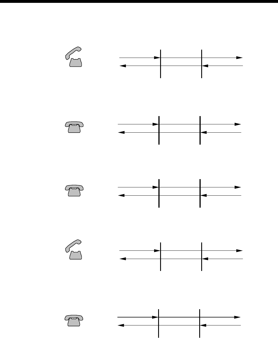
Appendices 6-49
© 1993–2000 Jtec Pty Limited
ARD T1 2. Answer/Active
ARD T1 3a. Clear Forward (from Active)
ARD T1 3b. Return to Idle
ARD T1 4a. Clear Backward (from Active)
ARD T1 4b. Return to Idle
ALEM T1M
Speech
Off Hook AB = 00
SEIZE
ANSWER
AB = 00
Speech
Battery
ALEM T1M
On Hoo
k
CLEAR FWD
ANSWER
AB = 00Batter
y
AB = 11
ALEM T1M
On Hook AB = 11
IDLE
IDLE
AB = 11Batter
y
ALEM T1M
Off Hook AB = 00
SEIZE
CLEAR BKW
AB = 11Battery
ALEM T1M
On Hook AB = 11
IDLE
IDLE
AB = 11Batter
y
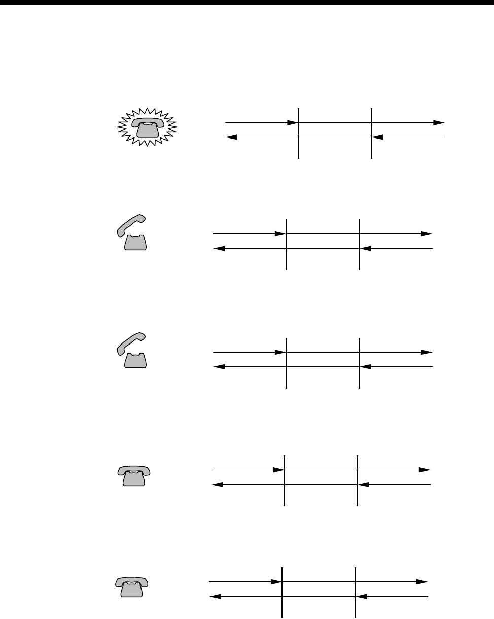
6-50 Appendix O
10003497.00 Rev.5
Far End CB Initiates Call
ARD T1 1. Seize/Alerting
ARD T1 2. Answer/Active
ARD T1 3a. Clear Forward (from Active)
ARD T1 3b. Return to Idle
ARD T1 4a. Clear Backward (from Active)
ALEM T1M
On Hook
ALERTING
SEIZE
AB = 00Ring Current
Ring Tone
AB = 11
ALEM T1M
Speech
Off Hook AB = 00
ANSWER
SEIZE
AB = 00
Speech
Batter
y
ALEM T1M
Off Hook AB = 00
SEIZED
CLEAR FWD
AB = 11Batter
y
ALEM T1M
On Hook AB = 11
IDLE
IDLE
AB = 11Batter
y
ALEM T1M
On Hook
CLEAR BKW
ANSWERED
AB = 00Batter
y
AB = 11
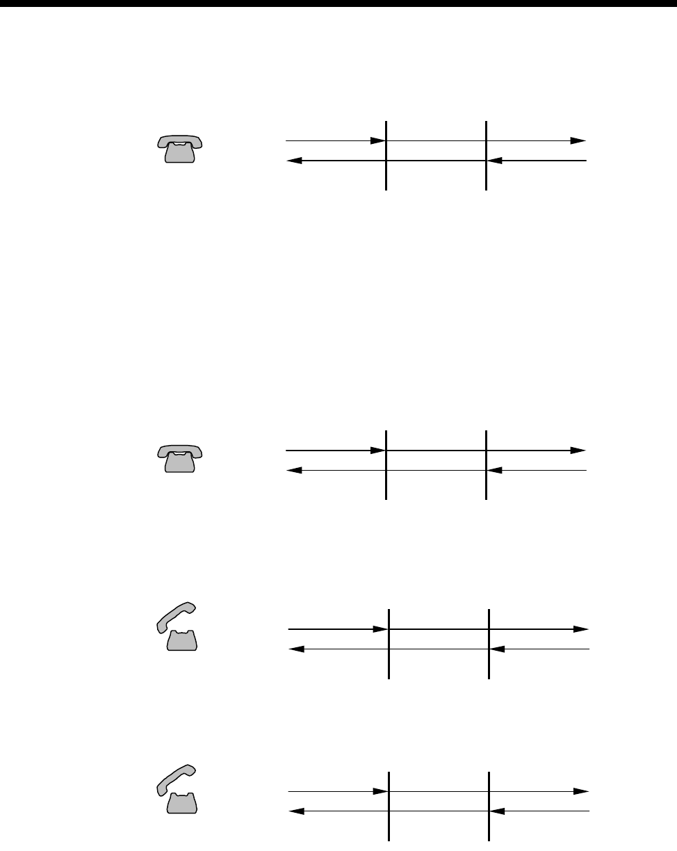
Appendices 6-51
© 1993–2000 Jtec Pty Limited
ARD T1 4b. Return to Idle
E1M (ARD)
The E1M ARD signalling protocol has the following CAS AB bit states.
•On-hook Signal: AB = 11
•Off-hook Signal: AB = 01
The E1M only evaluates the input A bit for signal change.
ARD E1 Idle State
Near End CB Initiates Call
ARD E1 1. Seize/Alerting
ARD E1 2. Answer/Active
ALEM T1M
On Hook AB = 11
IDLE
IDLE
AB = 11Batter
y
ALEM E1M
On Hook AB = 11
IDLE
IDLE
AB = 11Batter
y
ALEM E1M
Off Hook AB = 01
SEIZE
ALERTING
AB = 11
Ring Tone
Batter
y
ALEM E1M
Speech
Off Hook AB = 01
SEIZE
ANSWER
AB = 01
Speech
Batter
y
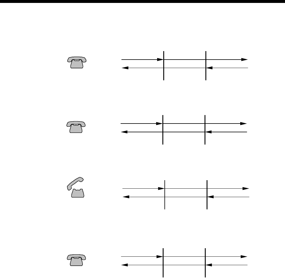
6-52 Appendix O
10003497.00 Rev.5
ARD E1 3a. Clear Forward (from Active)
ARD E1 3b. Return to Idle
ARD E1 4a. Clear Backward (from Active)
ARD E1 4b. Return to Idle
ALEM E1M
On Hoo
k
CLEAR FWD
ANSWER
AB = 01Batter
y
AB=11
AB = 11
ALEM E1M
On Hook AB = 11
IDLE
IDLE
AB = 11Battery
ALEM E1M
Off Hook AB = 01
SEIZE
CLEAR BKW
AB = 11Batter
y
ALEM E1M
On Hook AB = 11
IDLE
IDLE
AB = 11Battery
Appendices 6-53
© 1993–2000 Jtec Pty Limited
Far End CB Initiates Call
ARD E1 1. Seize/Alerting
ARD E1 2. Answer/Active
ARD E1 3a. Clear Forward (from Active)
ARD E1 3b. Return to Idle
ARD E1 4a. Clear Backward (from Active)
ALEM E1M
On Hook
ALERTING
SEIZE
AB = 01Ring Current
Ring Tone
AB = 11
ALEM E1M
Speech
Off Hook AB = 01
ANSWER
SEIZE
AB = 01
Speech
Battery
ALEM E1M
Off Hook AB = 01
SEIZED
CLEAR FWD
AB = 11Battery
ALEM E1M
On Hook AB = 11
IDLE
IDLE
AB = 11Batter
y
ALEM E1M
On Hoo
k
CLEAR BKW
ANSWERED
AB = 01Batter
y
AB = 11
6-54 Appendix O
10003497.00 Rev.5
ARD E1 4b. Return to Idle
T1M (MRD)
The T1M E&M Immediate Start signalling protocol has the following RBS AB bit
states:
•On-hook Signal: AB = 00
•Off-hook Signal: AB = 11
The T1M only evaluates the input A bit for signal change.
MRD T1 Idle State
Near End CB Initiates Call
MRD T1 1. Ring On
MRD T1 2. Ring Off
ALEM E1M
On Hook AB = 11
IDLE
IDLE
AB = 11Batter
y
IDLE
EMM T1M
Earth Off AB = 00
IDLE
AB = 00Earth Off
~
Switch Open
ADAPTER
EMM T1M
Earth On AB = 11
RING ON
IDLE
AB = 00Earth Off
~
Locall
y
Generated Ring
Switch Closed
ADAPTER
EMM T1M
Earth Off AB = 00
RING OFF
IDLE
AB = 00Earth Off
~
Switch Open
ADAPTER
Appendices 6-55
© 1993–2000 Jtec Pty Limited
MRD T1 3. Speech
Far End CB Initiates Call
MRD T1 1. Ring On
MRD T1 2. Ring Off
MRD T1 3. Speech
EMM T1M
Earth Off AB = 00
IDLE
AB = 00Earth Off
~
Switch OpenADAPTER
EMM T1M
Earth Off AB = 00
IDLE
RING ON
AB = 11Earth On
~
Switch OpenADAPTER
EMM T1M
Earth Off AB = 00
IDLE
RING OFF
AB = 00Earth Off
~
Switch OpenADAPTER
EMM T1M
Earth Off AB = 00
IDLE
IDLE
AB = 00Earth Off
~
Switch OpenADAPTER
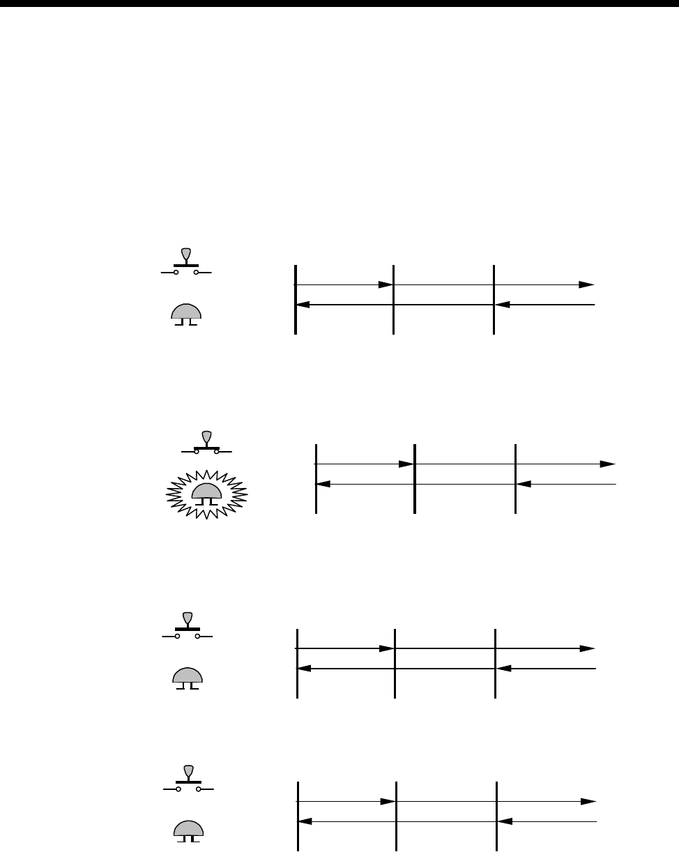
6-56 Appendix O
10003497.00 Rev.5
E1M (MRD)
The E1M MRD signalling protocol has the following CAS AB bit states.
•On-hook Signal: AB = 11
•Off-hook Signal: AB = 01
The E1M only evaluates the input A bit for signal change.
MRD E1 Idle State
Near End CB Initiates Call
MRD E1 1. Ring On
MRD E1 2. Ring Off
MRD E1 3. Speech
IDLE
EMM E1M
Earth Off AB = 11
IDLE
AB = 11Earth Off
~
Switch Open
ADAPTER
IDLE
EMM E1M
Earth On AB = 01
RING ON
AB = 11Earth Off
~
Locall
y
Generated Ring
Switch Closed
ADAPTER
EMM E1M
Earth Off AB = 11
RING OFF
IDLE
AB = 11Earth Off
~
Switch OpenADAPTER
IDLE
EMM E1M
Earth Off AB = 11
IDLE
AB = 11Earth Off
~
Switch OpenADAPTER
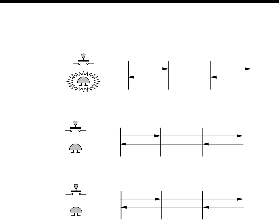
Appendices 6-57
© 1993–2000 Jtec Pty Limited
Far End CB Initiates Call
MRD E1 1. Ring On
MRD E1 2. Ring Off
MRD E1 3. Speech
EMM E1M
Earth Off AB = 11
IDLE
RING ON
AB = 01Earth On
~
Switch OpenADAPTER
EMM E1M
Earth Off AB = 11
IDLE
AB = 11Earth Off
~
Switch Open
ADAPTER
IDLE
EMM E1M
Earth Off AB = 11
IDLE
AB = 11Earth Off
~
Switch OpenADAPTER

6-58 Appendix P
10003497.00 Rev.5
Appendix P
PBX compatibility
This appendix details the PBXs that have been tested successfully with our
equipment. The table below shows the PBX and its software release level against the
Jtec equipment associated with the test. For J1000, the product release level is given.
For J5000, the Resource Manager Version is provided.
Note This table only supplies details of known systems against which our equipment has
been tested. Please contact Jtec Customer Service and Support for information on systems not
covered in this table.
PBX Type PBX
software
level
Jtec Model Protocol
Tested
J1000
Release J5000 RM
Version
Nortel Meridian Option 51 16 9.1 N/A DPNSS
Ericsson MD110 BCS 6.3.2 9.1 N/A DPNSS
GPT SL1 X81 9.1 N/A DPNSS
Nortel Meridian Option 61 21 9.1 N/A DPNSS
Mitel SX 2000 M24.2.0 10.1 N/A DPNSS
Nortel Meridian Option 11 18 10.1 N/A DPNSS
Nortel Meridian Option 51 18 10.1 N/A DPNSS
Ericsson MD110 BC 7.21 10.1 N/A DPNSS
Siemens iSDX 3000 4.1 11.1 N/A DPNSS
Nortel Meridian Option 11 20.19 11.1 N/A DPNSS
Lucent Definity G3 V6i30.0.223.5 12.1 N/A QSIG &
DPNSS
N/A RM Ver. 2.16 QSIG
Ericsson MD110 BC9 & BC10 N/A RM Ver. 1.56 DPNSS
Ericsson Mobility Server 1.4 & 2.0 N/A RM Ver. 1.56 QSIG
Nortel Meridian Option 11C 22.46 & 23.47 N/A RM Ver. 2.16 DPNSS
Nortel Meridian Option 81C 22.46 N/A RM Ver. 2.16 DPNSS
Nortel Passport 6480 5.0.14 N/A RM Ver. 2.16 QSIG
Siemens iSDX 6.1 N/A RM Ver. 2.14 DPNSS
Siemens Hycom 300 3.51 N/A RM Ver. 2.05 QSIG
Siemens Hycom 300 B3.513.16 N/A RM Ver. 2.05 QSIG

Appendices 6-59
© 1993–2000 Jtec Pty Limited
Appendix Q
Constant- and Variable-delay Subrate switches
This appendix details the number of constant- and variable-delay Subrate switches
(SRS) available in each listed module:
Module Version No. of
Constant-delay
SRS
No. of
Variable-delay
SRS
SRMM All 0 32
LDCM All 0 12
MFCM Pre V5.01 0 12
MFCM (with MLQ-CMP) V5.01 onwards 12 0
MFCM (with HD-VCM) All 16 0
COMBO Pre V5.01 0 24
COMBO (with VC-G7231-2) V5.01 onwards 24 0
COMBO (with HD-VCM) All 16 0
HSDM All 24 0
VCM All 0 32
6-60 Appendix R
10003497.00 Rev.5
Appendix R
Working with V.90 technology
This appendix contains additional information on V.90 technology. It also provides
tips for operating the DMM-56K module.
V.90 Technology
Compared to conventional modems, V.90 technology allows dial-up client modems
to receive data from the PSTN at much higher speed (up to 56 kbit/s). This increase
in performance results because the interior of the PSTN network is composed of
all-digital circuits, which are much less prone to error in the presence of electrical
noise than analog circuits. However by its very nature, the digital network limits the
speed obtained in the reverse direction (typically to 33.6 kbit/s or less) due to the
analog-to-digital conversion process required at the digital network edge.
Digital PSTN Networks
The PSTN network was originally designed for voice transmission and so consisted
of analog lines and switches. However, over the last two decades, the interior of the
PSTN network has been progressively upgraded to use all-digital, switched circuits
(for example, ISDN B-channels). This means that the only remaining analog portion
of the network is the copper line joining the customer premises to the central office
(CO) switch in the local telephone exchange. A typical call connection from a user’s
modem to a digital V.90 modem system (such as a DMM-56K) centrally located in the
PSTN network can therefore be shown as follows:
In the upstream direction (from the user modem to the central-site), the user signal
is converted into tones and transmitted over the analog network (local loop)
connection to the CO switch at the PSTN network edge. The CO switch samples the
analog input 8000 times a second, and converts these samples to 8-bit PCM codes
using an analog-to-digital converter (ADC). The resulting digital signal is transported
over the digital portion of the PSTN network to the central-site V.90 modem.

Appendices 6-61
© 1993–2000 Jtec Pty Limited
Quantization Noise Limits Signalling Speed
When a continuous analog signal is converted to a discrete digital signal (in this case
8-bit PCM codes), information is lost from the analog signal. The difference between
an original analog sample and its digitally encoded value is called quantization noise.
This noise fundamentally limits the speed at which information can be sent over the
channel. For this reason, V.90 analog modems use conventional modem modulation
techniques to transmit in the upstream direction, leading to speeds of 33.6 kbit/s (or
less depending on analog line noise) in this direction [1].
Achieving 56 kbit/s Speeds
From the above it is clear that analog-to-digital conversion introduces noise into the
communications channel and therefore limits the maximum data speed obtained on
the channel. However in the case of digital-to-analog conversion (DAC), where each
unique 8-bit PCM code is converted into a correspondingly unique voltage level, no
quantization noise is injected in the channel.
Referring to the figure above, we conclude that when the central-site V.90 modem is
digitally connected to the CO switch, and there are no analog-to-digital conversions
between the CO switch and the client modem’s receiver, the communications path is
not affected by quantization noise - these are the key requirements that enable a V.90
modem systems to achieve 56 kbit/s in the downstream direction [1,2].
Downstream V.90 Connections
In the downstream direction (from the central-site to the users modem) V.90 modems
encode transmitted information using the same 256 (8-bit PCM) code words used for
signalling across the digital portion of the PSTN network. At the CO switch, the DAC
converts the received PCM codes into the (unique) voltage levels that are transmitted
across the analog (local loop) circuit to the client modem receiver.
Under good line conditions, the transmitted voltage levels arrive at the client modem
receiver without information loss. The client modem can therefore recover the digital
PCM values transmitted by the central-site modem by examining the received levels.
However, network impairments (such as noise) introduce decoding errors.
Network Impairments
In practice, error sources (for example, analog noise, echo, and crosstalk), inter-office
PABX systems, and regulation of the maximum transmitted signal power allowed in
some Telecommunications administrations, are the determining factors that limit the
downstream speed to something less than 56 kbit/s.
Local Loop Noise
Network DACs follow non-linear conversion rules (µ-law PCM in the USA, A-law
PCM in the rest of the world). Though adequate for voice communications, the
non-linear rules present difficulties for V.90 modems in the presence of noise sources
in the analog local loop.

6-62 Appendix R
10003497.00 Rev.5
The PCM codes representing low voltages produce smaller step changes in the DAC
output voltages than PCM codes representing large values. Thus, analog noise in the
local loop affects the closely spaced low voltage levels more than the larger levels. In
practice, excess noise in the local loop means some proportion of the 255 PCM codes
must be excluded from signalling scheme used by the V.90 central-site modem.
During call setup, the DMM-56K V.90 modems probe the downstream path to remove
the PCM codes most susceptible to noise from the signalling scheme. The more noise
encountered in the local noise, the greater the number of PCM codes eliminated. The
result is a reduction in the maximum downstream speed (the rate is reduced by 1333
bit/s for each PCM code eliminated).
Local Equipment
Poor quality or noisy line terminations at the client end of the call can lead to further
reductions in the maximum V.90 receive speeds achieved in practice. Equipment (for
example, answering machines and cordless phones) sharing the same wall-socket as
the client V.90 modem can be a source of additional noise in the local loop, and will
therefore limit the maximum V.90 receive speed of the client modem. Disconnecting
such devices may significantly improve the receive speed.
Office PABX Systems
Clients dialling through PABX devices often experience poor V.90 speeds. A PABX is
a digital system that, apart from call switching, provides advanced features like voice
mail, and call re-direction. However, these features come at a cost to the V.90 modem
client, since a PABX uses analog-to-digital conversion on all inputs, and, in particular
signals coming from a central-site V.90 modem.
During call setup, DMM-56K V.90 modems examine the downstream path to detect
downstream analog-to-digital converters (such as those used in a PABX). When these
are detected, the DMM-56K connects the call using a lower speed modem modulation
standard (for example, V.34 or earlier modem standards).
FCC Regulation (USA only)
Due to FCC regulations, the maximum transmit speed in V.90 is limited to 53 kbit/s,
even under the best line conditions. This is not a limit on speed as such - instead, to
minimize crosstalk on the PSTN network, the FCC regulations restrict the amount of
signal power transmitted to -12dBm. To meet this low power limit, V.90 central-site
modems must use a subset (not all) of the 255 PCM codes, which limits the speed to
around 53 kbit/s in FCC governed administrations.
Variable Network Paths
Modem users dialling in from a fixed location that ordinarily makes high-speed V.90
connections to the central-site, may at times experience poor V.90 connections to this
same central-site. The pathway from the client-site through the digital portion of the
PSTN network is not always the same. For example, the poorer quality pathway may
include analog-to-digital conversions internal to the network (transcoding), different
line balance amplifiers, and/or automatic network gain systems (digital pads), all of
which cause lower speed V.90 connections.

Appendices 6-63
© 1993–2000 Jtec Pty Limited
Operating tips for the DMM-56K
The following paragraphs provide additional operating tips for the DMM-56K
module.
Modem Call Setup
During call setup, the DMM-56K V.90 modems examine the downstream path to
detect downstream analog-to-digital converters (such as those used in a PABX). When
these are detected, the DMM-56K connects the call using a lower speed modem
modulation standard (for example, V.34 or earlier modem standards). If the remote
client modem requests a connection at V.34 (or lower standard) the DMM-56K
attempts to connect the call using the requested modem standard.
Modem Connect Speeds
V.90 56 kbit/s speeds can only be achieved in the downstream direction (i.e., from
the DMM-56K module to the remote user modem. In the reverse direction the data
speed is typically limited to 33.6 kbit/s or less.
A modem usually produces a CONNECT XXXXX response once it connects and then
negotiates the call parameters with a remote modem. Approximately 10 seconds into
the call, the modems re-negotiate the call rate upward (or downward) based on their
individual measurements of the maximum sustainable rate obtained by analysing
the connection in data mode. The resulting call rate may differ from the rate displayed
in the modem CONNECT XXXXX response.
Data Compression
Modem data compression methods (V.42 bis, MNP 5) cannot be used to achieve data
rates greater than 57.6 kbit/s because the data rate across the backplane from a
DMM-56K modem to an FSM is limited to 57.6 kbit/s. Therefore, remote client
modems should disable data compression if the uncompressed rate could exceed the
57.6 kbit/s limit. Nonetheless, more efficient compression can be achieved across the
link using the data compression features provided by the FSM (data compression at
the PPP level, as controlled by the CCP - compression control protocol).
Windows Dial-Up Networking
If you enable the option ’bring up terminal screen after dialling’ when using Windows
95/NT Dial-Up Network Client to connect to the central-site FSM, you may or may
not see the characters ’+++AT&V2’ printed on the terminal screen prior to the FSM
login prompt. Some login scripts may fail on seeing these characters. Well-designed
scripts typically scan for the string ’ogin:’ and will thus work as expected.

6-64 Appendix S
10003497.00 Rev.5
Appendix S
Management Calls across OnRamp Xpress
Telstra, Australia’s OnRamp Xpress service provides only one in-dial number on the
link when the Xpress tariff is applied to a Basic Rate service.
When using OnRamp Xpress with either TimeFrame or Subrate Virtual Lines, ensure
that the Virtual Line has a Line Number with a Subaddress. This line number must
be the in-dial number that is allocated to the Xpress service. The Subaddress can be
arbitrarily allocated. The OmniVision Manager Number must then be set as the
in-dial number of the Xpress service.
Incoming calls with the correct Subaddress will match onto the appropriate Virtual
Line, while an incoming management call from OmniVision without a Subaddress
will correctly match onto the Manager Number.
Subaddressing
Subaddressing is not available on the Manager Number, the Router Table or the
CLI/Number Checking.
The first two restrictions imply that the Manager Number must always be the in-dial
number without a Subaddress.
If you are using CLI/Number Checking, only the line number portion of the number
can be changed, not the Subaddress. Likewise, when using TimeFrame and
CLI/Number Checking, the number to be changed must be changed to the Hotline
Number set in the TimeFrame Virtual Line Call Establishment Mode, excluding any
Subaddress that may be used. This allows the calls to be matched and directed across
the correct TimeFrame Virtual Line.

Glossary 7-1
© 1993–2000 Jtec Pty Limited
7Glossary

7-2 Glossary
10003497.00 Rev.5
2B+D ISDN transmission type comprising two 64 kbit/s B-channels and one 16
kbit/s D-channel.
30B+D ISDN transmission type comprising thirty 64 kbit/s B-channels and one 64
kbit/s D-channel.
ALEM Analog Line Exchange Module.
ALPM Analog Line Phone Module.
Advice Of Charge (AOC) a subscribed supplementary service supplied by the
ISDN provider. The service provides the cost of nominated outgoing calls.
Charging information is provided in the form of units, $ per unit and packet charges
on a per call basis.
analog (analogue) an electrical signal which varies constantly in voltage. This is
unlike a digital signal which varies between two constant values, usually denoted as
0 and 1.
The value of the analog signal varies continually during transmission, whereas a
digital signal only ever changes between two set values without any intermediate
variations. See also digital.
Associated Lines List a list of all the lines which are members of a lineset.
area code telephone number prefix representing a geographic area.
asynchronous a way of transmitting data whereby each information character, or
sometimes each word or small block, is individually synchronised. This is usually
achieved by labelling the beginning and end of each character with additional bits,
known as start and stop bits.
Also known as start/stop transmission. See also synchronous.
AT commands set of commands used by the Asynchronous Digital Line Module
(ADLM V.24, QDLM V.24).
Austel (Australian Telecommunication Authority) national body responsible for
setting and regulating telecommunications standards for network carriers and CPE
within Australia.
Austpac a Telstra, Australia public packet switched data service. It is a flexible data
network which can handle synchronous and asynchronous data streams of various
speeds and protocols.
Auto Answer used when the called DTE is not using X.21 circuit switched call
establishment and clearing procedures. An incoming call will be automatically
answered.
BABT British Approvals Board for Telecommunications, the United Kingdom
National approvals authority.
bandwidth range of signal frequencies that can be carried on a communication
channel.

Glossary 7-3
© 1993–2000 Jtec Pty Limited
B-channel (also known as the bearer channel) an ISDN 64 kbit/s channel that carries
customer information such as encoded voice, circuit-switched or packet-switched
data.
base number can be defined when you configure IPMTs and BRMTs. It is
subtracted from an incoming called party number and the call is directed to the line
with the resulting number, for example:
4507020 (incoming) - 4507000 (base) = 20 (line called).
The base number is also added to the area code and line number to generate the 8
digit national significant number which is sent as the calling party number on
outgoing calls, for example:
20 (line calling) + 4507000 (base) + 2 (area) = 24507020.
Basic Rate ISDN transmission type comprising two 64 kbit/s B-channels for user
transmission and one 16 kbit/s D-channel for common channel signalling.
baud (Bd) a unit of signalling speed of a data transmission device. The speed
expressed in bauds (Bd) reflects the number of discrete conditions or signal events
per second.
BCAM B-Channel Aggregation Module.
bearer service the communication link of a service that provides for the
transmission of digital information (for example, digitised voice and data) between
user devices.
bidirectional a link whereby it is possible to transfer information simultaneously
in both directions between two points.
bit (contraction of binary digit) a binary unit of information that can have one of
two values — 0 or 1.
bit Rate rate of data transmission.
bit/s (also bps and bits/s) bits per second. Used to describe data transmission rate.
BOOTP Bootstrap Protocol.
BRA (Basic Rate) ISDN transmission type comprising two 64 kbit/s B-channels and
one 16 kbit/s D-channel.
BRMN Basic Rate Module Network.
BRMT Basic Rate Module Terminal.
broadcast a unidirectional transmission to multiple receiving locations
simultaneously.
byte a small group of bits, usually 8, that combine to represent a character or
measurement of memory capacity.

7-4 Glossary
10003497.00 Rev.5
call the temporary connection (or apparent connection, as perceived by the caller)
of one terminal to another; for example, a telephone call.
Calling Line Identification and Verification Enhancement (CLIVE) an optional
Jtec feature that can be fitted to any J1000/J5000 system.
Calling Party Number the number from which an incoming call originates.
Called Party Number the number to which an incoming call is directed.
call control a function performed by the network layer (layer 3) of communications.
It provides call routing, number analysis, and call setup and clearance services.
Call Log call logging facility, which records details of sessions, module function and
errors.
CAS (Channel Associated Signalling) a signalling method in which traffic signals
carried by a single channel are transmitted in the channel itself or in a signalling
channel permanently dedicated to it.
E1 modules incorporate a CAS option.
Timeslot 16 is used as the dedicated signalling channel for timeslots 1 - 15 and
17 - 31.
CCITT see ITU-T.
CCS Common Channel Signalling; for example, the D-channel of ISDN Primary
Rate and Basic Rate interfaces.
CELP (Code Excited Linear Prediction) The voice compression coding technique
used by the Low Delay CELP Module (LDCM).
channel a conceptual pipe that represents a specific portion of the information
carrying capability of an interface, through which information (for example, control
signals, voice, data) may be transported.
CLI/Number checking (Calling Line Identification or Calling Party Number
checking). Means that calls can be accepted or rejected on the basis of the calling
party’s number.
CLI/Number list a list of calling party numbers against which incoming calls are
checked. A list may be global, effecting all lines, or specific, affecting particular lines
only.
CLIR (Call Line Identification Restriction) a Telstra service to which you can
subscribe.
configuration set of values which control the operation of the device.
Configure mode mode which allows you to set or change values for the device
parameters.

Glossary 7-5
© 1993–2000 Jtec Pty Limited
cyclic hunting a method of searching linesets for an appropriate line to which to
direct a call. The search always starts one member further down the Associated Lines
List than the previous call, regardless of whether that call was successful. This ensures
that calls are distributed as evenly as possible amongst members, and that lines that
are faulty but not blocked will not cause the service to fail continuously.
D-channel (also delta channel) an ISDN 64 kbit/s (Primary Rate) or 16 kbit/s (Basic
Rate) channel that carries common channel signalling and user-to-user information.
data bit rate rate of data transmission (in bit/s).
Data Communications Equipment (DCE) equipment that establishes, maintains
and terminates a connection.
Data Terminal Equipment (DTE) equipment which converts user information into
data signals for transmission, and vice-versa, for example, a PC.
default a value which is present unless changed.
digital a signal that takes only one of two values, normally denoted as 0 or 1, during
transmission. This is in contrast to an analog signal which can take any value between
a minimum and maximum at any particular time during transmission. See also analog.
DLM Digital Line Module.
DOS Disk Operating System.
DTMF (Dual Tone Multiple Frequency) a signalling scheme that uses two audio
tones to pass dialled numbers to the network.
DTR (Data Terminal Ready) control lead on V.24 and V.35 digital line cards.
Defined as Interchange Circuit No.108.
duplex transmission data transmission in both directions, either simultaneously
(full duplex) or alternately (half duplex).
E1M Exchange 1 Module.
E2E answer xfer end-to-end answering mechanism to support inter-PABX
operation.
en bloc dialling a dialling system in which the number is transmitted as an entity.
end-to-end signalling signalling between parties at either end of a link,
independently of the link signalling.
error a discrepancy between a computed, observed or measured value or condition
and the true, specified or theoretically correct value or condition.
extension (Extn, Xtn) a locally provided terminal equipment service, for example,
a telephone which is connected to a PABX.

7-6 Glossary
10003497.00 Rev.5
facsimile (fax)
1. The process of scanning a document, converting the image into electrical signals
for transmission to a remote receiver, and the conversion of the received signals into
a copy of the original document.
2. A machine that performs the facsimile process.
3. The copy document that is produced by the facsimile process.
G.703 the ITU-T (CCITT) standard for the physical traits of transmissions over
digital circuits.
gain increased signal power, usually after the signal passes through an amplifier,
repeater or antenna. Normally expressed in decibels (dB).
The opposite of gain is loss (or attenuation), which is often described as negative gain.
group number allocated main directory number within the range allocated by
ISDN provider. It is written on the label of the NT1.
Hotline dialling provides rapid call connection to the number sent in the setup
message.
Hotline number a number which is sent in the setup message to provide rapid call
connection.
I.460 ITU-T (CCITT) recommendation.
I.461 ITU-T (CCITT) recommendation – equivalent to X.30.
I.463 ITU-T (CCITT) recommendation – equivalent to V.110 and ECMA102.
icon a symbol used by an operating system or application to represent an event,
object, tool, command, etc.
IDD (International Direct Dial) the facility whereby network service provider
customers can place unassisted international calls to other customers.
Information Element (IE) information about the type of call and its destination is
conveyed in messages to the network exchange (ISDN) by the user equipment. These
messages are made up of various Information Elements, some of which are
mandatory, others optional.
input/output (I/O) a general term for the equipment used to communicate with a
computer; also the data involved in such communication.
interface a boundary between two systems, or two parts of one system, across
which all of the signals that pass are carefully defined.
The definition includes the connector signal levels, impedance, timing, sequence of
operation, and the meaning of signals.
IP Internet Protocol.
IPX Internet Packet Exchange.

Glossary 7-7
© 1993–2000 Jtec Pty Limited
IPMN ISDN Primary Rate Module Network.
IPMT ISDN Primary Rate Module Terminal.
ISDN Integrated Services Digital Network. An ITU-T (CCITT) standardised
telecommunications service that provides for the transmission of voice, data and
image, and a common channel digital signalling system. End-to-end digitised voice
and data traffic is handled simultaneously on the same links via the same exchanges.
Network access includes Basic Rate (2B+D ~ 144 kbit/s) and Primary Rate (30B+D ~
2.048 Mbit/s).
ISDN is defined in the ITU-T (CCITT) I.400 series.
ISDN port interface to the ISDN.
ITU-T International Telecommunications Union - Telecommunications, formerly
the CCITT (Comité Consultatif International de Télégraphie et de Téléfonie). The
International Telecommunications Union is a part of the United Nations. It publishes
a set of recommendations, which are used by equipment providers and service
providers worldwide. Examples of ITU-T recommendations are X.25, V.24 and G.703.
ITU-T recommendations recommendations of the International
Telecommunications Union, formerly the CCITT (Comité Consultatif International
de Télégraphie et de Téléfonie). Relevant recommendations are shown in Appendix B.
kbit/s (also called kbps and kbits/s) kilobits per second (thousand bits per second).
Used to describe data transmission rate.
layer a collection of related network-processing functions that together comprise
one step of a hierarchy of functions. For example, the OSI reference model has seven
layers.
LED (Light Emitting Diode) a semiconductor junction diode that emits light in either
the visible or non-visible range. Uses include alphanumeric displays, status indicators
(for example, power on/off, alarm reported, etc.) and light sources for fibre optic
communications.
line a concept. Not necessarily a physical port, and not necessarily on the user or
network side. An ALEM has four lines and an E1M has 31. We use a physical line
number (for example, ALEM lines 1 top to 4 bottom), and a Line Number entered in
the Line Configuration dialog box which is used to match the phone number of the
line.
linear hunting a method of searching linesets. The search always starts at the top
of the Associated Lines List. The call is directed to the first idle member on the list.
lineset a range of ISDN numbers associated with a group of ports. Called numbers
in the range are directed to one of the ports. One or many numbers can be associated
with one or many ports.
local device one to which the NMS computer is connected via the serial port on the
Resource Manager, not over the ISDN.

7-8 Glossary
10003497.00 Rev.5
local number telephone number without area code, for example, 450 7000.
log record of events.
loopback a diagnostic facility to assist in the determination of data transfer faults.
The transmit and receive channels of a device are effectively connected, such that all
received information is immediately re-transmitted to the source. Often used in
conjunction with BERT (Bit Error Rate Testing) in digital systems.
Manager number a number defined in the CM and RM configuration which is
matched to the device in order to receive D-channel calls. If absent, all incoming
B-channel and D-channel calls are assumed to be for establishing a session between
OmniVision and the device, to allow configuration of an unconfigured chassis. Must
be numbered like other lines within the allocated ISDN range.
Mbit/s (also Mbps and Mbits/s) megabits per second (million bits per second). Used
to describe data transmission rate.
Microsoft Windows an operating system which provides a graphical user interface
for PCs.
mode a type of operation, for example, configure, monitor, etc.
modem (modulator/demodulator) device which transforms (modulates) a digital
bit stream into an analog signal, and vice-versa.
monitor port interface to a PC running Jtec’s Protocol Analyser Package (PAP).
MS-DOS Microsoft Disk Operating System.
ms (millisecond) one thousandth of a second.
Multiple Subscriber Numbering (MSN) a numbering system used in the U.K.
multiplex the process of transmitting multiple signals from different sources over a
common cable, transmission line, or channel.
national significant number telephone number including the area code without
the first leading zero.
network a series of points, or nodes, connected by communications channels.
Network Termination 1 (NT1) device which terminates the ISDN on your
premises. The ISDN equivalent of a telephone socket.
Network Termination 2 (NT2) device between terminal equipment (TE) and the
network termination 1 (NT1) which provides switching and/or multiplexing
facilities.

Glossary 7-9
© 1993–2000 Jtec Pty Limited
Network Independent Clock (NIC) the clock of a digital synchronous device which
is carried over a synchronous network and reproduced at the other end. The digital
device clock is independent of the network clock. The ISDN low layer compatibility
element (LLC) allows this to be configured. Jtec does not provide this feature, but
provides access to the LLC to allow external devices to provide clock buffering.
node a point on a network that demands or supplies services, or where transmission
paths are interconnected, typically by means of switching.
non-volatile memory retains information even if the storage device is switched off.
NRZ Non Return to Zero. NRZ signals maintain constant voltage levels with no
signal transitions (no return to a zero voltage level) during a bit interval. See also
NRZI.
NRZI Non Return to Zero Inverted. NRZI signals maintain constant voltage levels
with no signal transitions (no return to a zero voltage level) but interpret the presence
of data at the beginning of a bit interval as a signal transition, and the absence of data
as no transition. See also NRZ.
octet a unit of data consisting of 8 bits (binary digits).
offline if NMS is offline, it is accessing the database file stored in the PC. There are
no active sessions.
OmniVision ™ Jtec’s Network Management Program. A Windows ™ 95, 98 or NT
application for configuring and managing Jtec’s products.
OmniVision Help online Help for OmniVision.
online a device is online if a session is established with the PC running OmniVision.
Optus an Australian carrier.
out-of-band signalling a signalling system in which signals are conveyed outside
the band of frequencies normally used for message transmission, but are carried on
(or are associated with) the transmission channel.
parity refers to the state of bits of data. Can be odd, even or none.
password the password required to leave Monitor mode, and to establish a session
with an unconfigured device is Jtec (case sensitive). The password can be changed
via OmniVision using either the Mode Menu, Set Mode Password command, or the
Device Menu, Set Password command.
PC (Personal Computer) an IBM or compatible PC is needed to run the NMS
software.
point-to-point a system in which all connections are permanent and direct.
port the physical entry and exit point (termination point) for information going into
and out of a module, that is, the user interface.

7-10 Glossary
10003497.00 Rev.5
PPP Point-to-Point Protocol.
Primary Rate (also PRA and 30B+D) an ISDN term that describes the 30B+D
interface, that is thirty 64 kbit/s transmission links and one 64 kbit/s signalling
channel. These are known as bearer links and the delta channel.
The ITU-T (CCITT) recommendation is the I.430 series.
Private Automatic Branch Exchange (PABX) (also PBX) a type of Customer
Switching System that connects to voice services via trunk lines that are provided by
the network service provider. Allows optionally unattended incoming, outgoing and
internal extension calls.
protocol a set of rules governing the information flow within a communications
infrastructure, otherwise known as data link control.
Protocols control format, timing, error correction and running order. Suites of
protocols are often used in networks, with each protocol responsible for one part of
a communications function.
Protocol Analyser Package (PAP) a Jtec package which runs on a PC and provides
a display analysis of the ISDN layer 2 and layer 3 protocols and reports on the status
of layer 1.
PSM Power Supply Module.
Public Switched Telephone Network (PSTN) The complete public telephone
system, including telephones, local and trunk lines, and exchanges.
Links are only held as long as a call is in progress. Local lines to telephones are usually
analog in nature.
RAM (Random Access Memory) a storage location where information can be
entered, stored and removed (written, held and overwritten), as required. A power
source is required to maintain the contents of the memory.
re-boot restart a PC, forcing DOS to be re-loaded.
To re-boot, press the Ctrl, Alt and Delete keys simultaneously.
relative level (dBr) the relative (power) level of a point in a transmission system is
the nominal power gain at the reference frequency, from a reference point to the point
considered.
Relative levels can be used to compare two or more points of a network with respect
to power. One point of a network is usually defined as the reference point at 0dBr,
from which other measurement points are derived.
remote device a device to which the NMS computer is connected over the ISDN.
RM Resource Manager.
retry try again.
S interface see ISDN port.

Glossary 7-11
© 1993–2000 Jtec Pty Limited
semipermanent connection (SPC) the equivalent of a tie line between two parties
through the ISDN, set up by the ISDN provider. Can be deactivated to free the
B-channel for other traffic. Applicable in Australia only.
semipermanent backup attempts a Hotline connection if the semipermanent
connection drops out for more than three seconds. OmniVision gives no indication
whether a semipermanent or switched call is operating. If a Hotline call is established,
it must be manually cleared. Backup should therefore be used with care. Applicable
in Australia only.
session refers to the relationship between the NMS PC and the device.
session status an indication of the relationship between the NMS PC and the
chassis, displayed in the window title bar:
Online session established between Omnivision and the chassis
Offline no session established between OmniVision and the chassis
Uploading configuration being sent from the chassis to OmniVision
Downloading database file being sent from OmniVision to the chassis
Connecting making connection between OmniVision and the chassis
signal a physical phenomenon whose characteristics may vary to represent
information.
SNMP Simple Network Management Protocol.
SPC (semipermanent connection) ISDN equivalent of a leased line. Applicable in
Australia only.
software lock a device which must be in place in the PC parallel port for
OmniVision to run. Prevents the unauthorised use of software.
SRMM Subrate Multiplexer Module.
stop bit bit that comes at the end of a character.
STP Spanning Tree Protocol.
subaddress a suffix to a line or Hotline number which is not interpreted by the
network. If a called party subaddress number Information Element (IE) is received
on an incoming call, the subaddress is checked against the configured line subaddress.
The line subaddress is sent, if configured, as the calling party subaddress IE on
outgoing calls.
subrack the chassis which functions as the equipment housing. 15 slot chassis are
designed to fit into standard 19 inch equipment racks. They measure 7 IU (that is, 7
x 44.5 mm) in height. Installation of a 1 IU vent panel above each subrack is
recommended to allow for adequate airflow.
Subrate and subchannel a rate or channel of less than 64 kbit/s, in multiples of 8
kbit/s, for example, 8, 32 and 56 kbit/s.

7-12 Glossary
10003497.00 Rev.5
supplementary service a type of telecommunication service that can only be used
in conjunction with one or more bearer or teleservice. A subscription service provided
by the ISDN provider.
synchronous a data transmission method whereby there is a constant interval
between the transmitted bits, obviating the need for start and stop bits that are
necessary for asynchronous transmission. Its sophistication allows for faster
transmission rates. The method does, however, demand that the two devices involved
in the interchange must be synchronised. This is achieved by one device providing
the clock (usually the DCE) and the other synchronising to it. The ISDN is a
synchronous network. See also asynchronous.
T309 an ISDN layer 3 timer. If T309 is enabled, calls are automatically cleared after
a certain time following a layer 2 failure. Primary Rate calls are cleared after 15
seconds. Basic Rate calls are cleared after 2 seconds.
The T309 disable option in OmniVision is only available for IPMTs and BRMTs with
a version number greater than 3.0.
Telstra an Australian carrier.
telecommunications any transmission and/or emission, and reception of signals
that represent signs, writing, images and sounds, or intelligence of any nature by wire,
radio, optical or other electromagnetic systems.
telephony a form of telecommunication that allows the transfer of speech,
bidirectionally and in real time.
telex teleprinter exchange network. System of text communication between
text-only teleprinters at 50 bit/s (6 characters per second).
Terminal Adaptor (TA) device that adapts non-ISDN equipment to a standard
ISDN interface, for example, a device that converts RS-232 to ISDN.
Terminal Equipment (TE) equipment that makes use of the ISDN.
TE1 has a standard ISDN interface (for example, a digital telephone).
TE2 does not have a standard ISDN interface (for example, an analog telephone), and
requires a Terminal Adaptor (TA).
test number defined in RM configuration, for diagnostic loopback testing of
B-channel connections to and from the device.
TFTP Trivial File Transfer Protocol.
tie line (also leased line) a private-line type communications channel that is used to
link two CCSs. Provides interworking and/or traffic transfer capabilities. Also known
as Tie Trunk and Leased Line.
Timelink ™ tariff system with high flag fall and small increment provided by
Telecom Australia on subscription. Mainly used for data transfer.
transmission the transfer of information from one point to another point, or points,
by means of signals.

Glossary 7-13
© 1993–2000 Jtec Pty Limited
unidirectional pertaining to a link where the transfer of information is possible in
one pre-assigned direction only.
V.24 asynchronous an asynchronous protocol recommended by ITU-T (CCITT) for
the transmission of data over telephone circuits via modems. see asynchronous.
V.24 synchronous a synchronous protocol recommended by ITU-T (CCITT) for the
transmission of data over telephone circuits via modems. see synchronous.
V.35 a protocol recommended by ITU-T (CCITT) for the transmission of data over
telephone circuits via modems.
Virtual Line a named group of lines which can be treated as one for call control
purposes. It has no physical attributes itself, but is defined by its members. The four
types of Virtual Line are:
•subrate multiplexed
•non-subrate multiplexed
•broadcast
•TimeFrame.
Windows Help comprehensive on-screen help provided with Microsoft Windows
packages.
X.21 a data protocol recommended by ITU-T (CCITT) to provide an interface for
circuit switched data networks and data terminal.
XSPC Switched Semipermanent Connection. A facility which attempts to
automatically re-establish a failed Hotline call at timed intervals.

7-14 Glossary
10003497.00 Rev.5

Index 8-1
© 1993–2000 Jtec Pty Limited
8Index

8-2 Index
10003497.00 Rev.5
A
Access Controller, 1-4
Active Call Facilities
Release call if busy tone detected, 2-13
Adding and deleting users, 3-12
ADLM V.24, 4-91
ALEM, 4-133
ALEM-2, 4-138
ALPM, 4-148
Indial operation, 6-17
ALPM-2, 4-153
Analog Line Exchange Module, 4-133
Configuration, 4-133, 4-139
Analog Line Exchange Module-2, 4-138
Configuration, 4-139
Analog line interfaces
Operating, 6-12
Analog Line Phone Module, 4-148
Configuration, 4-148
Analog Line Phone Module-2, 4-153
Configuration, 4-153
Analog Modules
Applications, 5-78
UDAS and IDAS signalling, 6-15
Analog modules
Applications, 5-78
AOC (Advice of Charge), 2-15
Applications
Analog line modules, 5-78
Channel Bank, 5-104
Dial Gateway, 5-99
DPNSS, 5-55
DTM, 5-52
Inband signalling, 5-43
Interworking, 5-34
IRM, 5-90
LDCM and MFCM, 5-47
Microplex switching, 5-27
QSIG, 5-66
Subrate Virtual Line, 5-24
TimeFrame Virtual Lines, 5-3
Virtual eXchange, 5-30
Virtual eXtension, 5-86
Area code, 2-5
AT Commands, 6-4
Conventions, 6-4
Format, 6-4
Result codes, 6-11
Audience, 1-2
B
Back Busy, 2-14
Base Number, 2-3
Basic Rate NT Module, 4-19
Configuration, 4-19
Basic Rate TE Module, 4-17
Configuration, 4-17
BCAM, 4-202
Call Establishment, 4-203
Data Source, 4-203
Port Configuration, 4-203
V.35, 4-202
X.21, 4-202
BCAM Configuration
Channel setup, 4-204
BCAM-ISO
Call Establishment Modes, 4-212
Call profile, 4-209
Configuration, 4-207
Data source and Call Control, 4-210
ISDN Line Controls, 4-213
Line configuration, 4-211
Port Configuration, 4-208
Using with IRM, 4-222, 5-94
B-channel Aggregation Module, 4-202
B-channel Aggregation Module-ISO, 4-207
BERT, 4-115
Configuration, 4-115
Bit Error Rate Testing, 4-115
Bootp, 3-9
BRMN, 3-47, 4-19
BRMT, 4-17
Broadcast Virtual Line, 3-56
C
Call Control, 2-14
AT, 2-14
C. Signal, 2-14
Connect after indialling digits, 2-14
DTR Call, 2-14
RS, 2-14
V.25bis, 2-14
X.21, 2-14
Call Direction, 2-10
incoming, 2-10
outgoing, 2-10
Callback, 5-39
Called party ID, 2-5
Calling Line Identification and Verification Enhance-
ment, 3-80
Calling Party Number, 3-80
CELP, 4-189
Channel Bank, 5-104
Automatic Ring Down, 5-104
Configuration, 5-107
Establishing connections, 5-116
Manual Ring Down, 5-104
Signalling, 5-105
T1 and E1 Signalling, 6-48
Tone Only, 5-104
CLI checking, 3-80
CLI List, 3-80
CLIP, 2-16
CLIR, 2-16, 3-80
CLIVE, 3-80
Clocking, 3-49
CM, 3-3
Code Excited Linear Prediction, 4-189
COMBO
HD-VCM, 4-183
COMBO Digital Line Module
Configuration, 4-177
COMBO Module, 4-168
Analog line configuration, 4-169
Digital interface configuration, 4-177
Compander, 2-15, 4-189
Concert, 3-86

Index 8-3
© 1993–2000 Jtec Pty Limited
Configuration
Analog Line Exchange Module, 4-133
Analog Line Exchange Module-2, 4-139
Analog Line Phone Module, 4-148
Analog Line Phone Module -2, 4-153
Basic Rate TE Module, 4-17, 4-19
BCAM-ISO, 4-207
B-Channel Aggregation Module, 4-202
COMBO Digital Line Module, 4-177
COMBO Module, 4-169
Control Module, 3-3
DBRM-U, 4-33
Digital Modem Module, 4-246
Digital Trunk Module, 4-85
DMM-56K, 4-246
Dual Basic Rate NT Module, 4-21
E&M Line Module, 4-162
E1 Digital Module, 4-37
E1M-DPNSS, 4-54
E1M-QSIG, 4-69
Frame Switch Module, 4-227
HSDM, 4-116
Integrated Router Module, 4-218
ISDN Gateway Module, 4-14
ISDN Primary Rate NT Module, 4-6
ISDN Primary Rate NT Module-T1, 4-9
ISDN Primary Rate TE Module, 4-3
ISDN Primary Rate TE Module-T1, 4-12
Leased Line Backup, 4-121
Low Delay CELP Module, 4-190
MFCM, 4-187, 4-198
QBRM-U, 4-33
Quad Basic Rate NT Module, 4-27
Quad Digital Line Module, 4-110
Resource Manager, 3-5
Signalling Access Module, 4-223
Subrate Switch Multiplexer Module, 4-200
T1M Digital Module, 4-44
V.24 Asynchronous Digital Line Module, 4-91
V.24 Synchronous Digital Line Module, 4-97
V.35 Synchronous Digital Line Module, 4-106
X.21 Synchronous Digital Line Module, 4-102
Control Leads
Local Only, 2-13
Transferred Inband, 2-13
Control Module, 3-3
Configuration, 3-3
Manager Number, 3-3
Test line, 3-4
Test Number, 3-4
Conventions, 1-3
D
Data Handler Service
Configuring, 3-25
Data Link Circuit Identifier, 3-23
Database
limitations, 6-28
DBRM, 4-21
DBRM-U, 4-33
Configuration, 4-33
D-channel, 3-3, 3-6
DDI (Indial), 2-12
Definitions, 2-3
Base Number, 2-3
Bearer Capability, 2-6
Call Establishment Modes, 2-11
Codec, 2-17
Dial Type, 2-17
High Layer Compatibility, 2-10
Hotline, 2-11
Line configuration, 2-5
Line Numbering, 2-15
Low Layer Compatibility, 2-7
Octet 3 Transfer, 2-7
Restriction, 2-17
Semipermanent, 2-11
Teleservice, 2-16
XSPC, 2-12
Dial Gateway
Configuring, 5-100
Dial Type
Both, 2-17
DTMF, 2-17
None, 2-17
Pulse, 2-17
Digital Line Module
Asynchronous V.24, 4-91
QDLM, 4-110
Synchronous V.24, 4-97
Synchronous V.35, 4-106
Synchronous X.21, 4-102
Digital Modem Module, 4-246
Digital Trunk Module, 4-79
Alarms, 4-84
Applications, 5-52
Clock source configuration, 4-80
Configuration, 4-85
Operation, 4-79
Remote configuration (Autosynchronise), 5-52
subB-channel usage, 4-85
Trunk numbering, 4-86
Trunk port interface options, 4-80
Trunk port setup, 4-86
Trunk quality reporting, 4-83, 4-90
Using the subB-channel, 5-54
V.35 interface, 4-80
X.21 interface, 4-80
DMM, 4-246
DMM-56K, 4-246
DPNSS, 4-49
Gateway Call Diversion, 4-52
Dual Basic Rate Module-U Interface, 4-33
Configuration, 4-33
Dual Basic Rate NT Module, 4-21
E
E&M Line Module, 4-162
Configuration, 4-162
E1 Digital Module (E1M), 4-37
E1 Digital Module NT
Configuration, 4-37
E1M, 4-37

8-4 Index
10003497.00 Rev.5
E1M-DPNSS, 4-49
Applications, 5-55
Bandwidth, 4-62
Configuration, 4-54
Gateway operation, 4-51
Intermediate nodes, 4-53
Number translation, 4-58
Numbering, 4-53
Operation, 4-49
Signalling paths, 4-59
Transparent operation, 4-50
E1MN Module
Line configuration, 4-38
E1M-QSIG, 4-64
Bandwidth, 4-77
Configuration, 4-69
Gateway operation, 4-66
Intermediate nodes, 4-67
Number translation, 4-73
Numbering, 4-67
Operation, 4-64
Signalling paths, 4-74
Transparent operation, 4-65
EMM, 4-162
EMM-2, 4-162
End-to-end Signalling
Interpreted, 6-16
Uninterpreted, 6-15
F
Fast Packet Switch, 3-32
Configuring, 3-32
Fax compatibility, 6-37
Flash management, 3-10
Frame Relay PVC management, 3-42
Frame Switch Module, 4-227
FSM
Configuration, 4-227
Files, 4-236
Finger, 4-245
Flash memory, 4-236
Frame Relay, 4-235
Line Control, 4-228
Login and Authentication, 4-233
Monitor, 4-244
Multilink PPP, 4-231
RADIUS, 4-232
Router, 4-243
Telnet, 4-241
TFTP, 4-244
G
Gateway Call Diversion, 4-52
Glossary, 7-6
H
HDLC Data Handler Service, 3-25
HD-VCM, 4-183, 4-194
High Layer Compatibility, 1-6
High Speed Data Module, 4-116
HLC, 2-10
Hotline, 2-11
Hotline number, 3-56
HSDM
Configuration, 4-116
Subrate switching, 4-120
I
IDAS, 6-15, 6-16
Inband signalling
Applications, 5-43
Call routing and connection, 3-75
Connecting Router Ports, 3-75
End-point addressing, 3-76
RM configuration, 3-77
Routers, 3-74
SAM, 3-75
SAM configuration, 3-78
Signalling end-points, 3-76
Simple point-to-point connection, 5-43
Simple tree network, 5-45
Inband Signalling facility, 3-74
Information Elements, 1-6
High Layer Compatibility, 1-6
Low Layer Compatibility, 1-6
Integrated Router Module, 4-215
Interworking, 3-57
Applications, 5-34
Compressed tie lines to switched calls, 5-36
Local call to an international number, 5-38
Switched calls between two networks, 5-34
Using a remote tie line to make switched calls, 5-35
Interworking Unit, 3-58
Interworking Unit Line, 3-58
IPMN, 3-47, 4-6
Configuration, 4-6
IPMN-GT
Configuration, 4-14
IPMN-T1, 4-9
Configuration, 4-9
IPMT, 4-3
Configuration, 4-3
IPMT-T1, 4-12
Configuration, 4-12
IRM, 4-215
B-channel rate, 4-219
Call options, 4-220
Configuration, 4-218
Group configuration, 4-218
Port identification, 4-221
Using BCAM-ISO as a utility, 4-222
WAN speed, 4-219
IRM applications, 5-90
IRM to HSDM, 5-96
IRM with a Digital Line module, 5-97
IRM with BCAM-ISO, 5-94
Linking multiple remote devices to a central site, 5-92
Multilinking IRM to IRM, 5-90
Subrate IRM and compressed voice, 5-98
Subrate primary and bandwidth on demand, 5-91
ISDN, 1-5, 3-3, 3-6
concepts, 1-6

Index 8-5
© 1993–2000 Jtec Pty Limited
ISDN Gateway Module
Configuration, 4-14
ISDN Interface
Bearer Capability, 2-6
Call Establishment Modes, 2-11
Codec, 2-17
Dial Type, 2-17
High Layer Compatibility, 2-10
ISDN Line Controls, 2-15
Low Layer Compatibility, 2-7
Outgoing TE, 2-19
PABX, 2-18
Restriction, 2-17
Service Tones, 2-18
Teleservice, 2-16
ISDN Interworking, 3-57
Call types, 3-60
Configuration, 3-61
Configuring IPMT, 3-66
Operation, 3-59
Resource Manager configuration, 3-61
ISDN Primary Rate NT Module, 4-6
Configuration, 4-6
ISDN Primary Rate NT Module-T1, 4-9
Configuration, 4-9
ISDN Primary Rate TE Module, 4-3
Configuration, 4-3
ISDN Primary Rate TE Module-T1, 4-12
Configuration, 4-12
ITU-T (CCITT) recommendations, 6-3
L
LAN IP Address, 3-9
LDCM, 3-67
Applications, 5-47
Compression Rates, 4-191
Configuration, 4-190
Private network with access to PTN, 5-48
Tie line application, 5-47
Transit node - voice and data, 5-48
Transit node-voice only, 5-48
Using with SAM, 5-49
Using with VCM, 5-50
Voice/fax network application, 5-49
Voice/Fax submodule, 4-189
Leased Line Backup, 4-121
Configuration, 4-121
Configuration for 56 or 64 kbit/s, 4-124
DCE-DTE control signals, 4-123
Default configuration, 4-123
Incoming backup calls, 4-122
Manual backup calls, 4-124
Multiple backup protection, 4-122
Outgoing backup calls, 4-122
X.21 interfaces, 4-124
Line configuration, 2-5
E1MN Module, 4-38
T1M Module, 4-44
Lineset, 2-5
Parameters, 3-48
Linesets, 3-46
Cyclic hunting, 3-47
Linear hunting, 3-47
LLB, 4-121
LLC, 2-7
Low Layer Compatibility, 1-6
incoming calls, 2-7
outgoing calls, 2-7
M
Management IP Address, 3-9
MFCM, 4-193
Applications, 5-47
Configuration, 4-187, 4-198
Configuring the Virtual Line, 4-188, 4-199
HD-VCM, 4-194
Mixed TimeFrame Network, 5-50
MP-MLQ mode options, 4-182, 4-194
Operation, 4-193
Selecting voice/data rates, 4-187, 4-198
MicropleX Switching, 3-67
Applications, 5-27
Configuration, 3-69
Demand established operation, 3-71
Manual connection, 3-70
SPC operation, 3-72
XSPC operation, 3-69

8-6 Index
10003497.00 Rev.5
Modules
ADLM V.24, 4-91
ALEM, 4-133
ALEM-2, 4-138
ALPM, 4-148
ALPM-2, 4-153
BCAM, 4-202
BCAM-ISO, 4-207
BRMN, 4-19
BRMT, 4-17
CM, 3-3
COMBO, 4-168
DBRM, 4-21
DBRM-U, 4-33
DMM, 4-246
DMM-56K, 4-246
DTM, 4-79
E1M, 4-37
E1M-DPNSS, 4-49
E1M-QSIG, 4-64
EMM, 4-162
EMM-2, 4-162
FSM, 4-227
HSDM, 4-116
IPMN, 4-6
IPMN-GT, 4-14
IPMN-T1, 4-9
IPMT, 4-3
IPMT-T1, 4-12
IRM, 4-215
LDCM, 4-189
MFCM, 4-193
QBRM, 4-27
QBRM-U, 4-33
QDLM, 4-110
RM, 3-5
SAM, 4-223
SDLM V.24, 4-97
SDLM V.35, 4-106
SDLM X.21, 4-102
SRMM, 4-200
T1M, 4-43
VCM, 4-201
Monitor commands, 6-40
MP-MLQ, 4-168, 4-189
Multi Function Compression Module, 4-193
Multilink PPP, 4-231
N
National ISDN 1 protocol, 4-24, 4-30
Default SPID, 4-24, 4-30
Network Simulation Task (NeST), 3-67
NI1 protocol, 4-24, 4-30
Node access
dual/multiple, 6-27
Non Subrate Multiplexed Virtual Line, 3-55
O
Octet 3 Transfer
Speech, 2-7
Unrest.Digital, 2-7
Octet 5 a-d, 2-8
Octet 5 Layer 1
A-law, 2-8
CCITT Rate Adaption, 2-8
non-CCITT Rate Adaption, 2-8
Octet 5a User Rate, 2-8
Octet 5c, 2-9
Octet 5c Data Bits, 2-9
Octet 5c Parity, 2-9
Octet 5c Stop Bits, 2-9
Octet 5d, 2-9
Octet 5d Duplex, 2-9
OmniVision, 1-5, 2-5
Outgoing CLI, 2-16
Outgoing TE
Any, 2-19
Exclusive, 2-19
Preferred, 2-19
P
PABX
Recall time, 2-18
PABX Recall, 2-14
Packet Channel Handler, 3-30
Configuring, 3-30
Packet Port
Backplane bandwidth allowance, 3-35
Subrate switch usage, 3-36
Parameters
Bearer Capability, 2-6
Call Establishment Modes, 2-11
Codec, 2-17
Dial Type, 2-17
High Layer Compatibility, 2-10
ISDN Line Controls, 2-15
Line Number, 2-5
Low Layer Compatibility, 2-7
Outgoing TE, 2-19
PABX, 2-18
Port ID, 2-5
Port Name, 2-5
Service Tones, 2-18
Subaddress, 2-5
PBX compatibility, 6-58
Permanent Virtual Circuits, 3-42
Phone Home, 3-87
Configuration, 3-88
PVC Management
Polling, 3-42
PVC management procedures
Example, 3-44
Q
QBRM, 4-27
Configuration, 4-27
QBRM-U, 4-33
Configuration, 4-33
QDLM, 4-110
Configuration, 4-110

Index 8-7
© 1993–2000 Jtec Pty Limited
QSIG
QSIG-ETSI supplementary services interworking, 6-
44
Quad Basic Rate Module-U Interface, 4-33
Configuration, 4-33
Quad Basic Rate NT Module, 4-27
Configuration, 4-27
Quad Digital Line Module, 4-110
Configuration, 4-110
R
RADIUS, 4-232
Rebooting the RM, 3-12, 6-43
Reference Master
modules, 3-49
Reference Master Priorities, 3-49
Resource Manager, 3-5
Configuration, 3-5
Configuring IP Address, 3-8
Flash management, 3-10
Line Number Matching, 3-7
Manager Number, 3-5
Packet Port, 3-34
Rebooting, 3-12, 6-43
Software image, 3-11
Telnet, 3-10
Test line, 3-6
Test Number, 3-6
TFTP, 3-13
Result codes, 6-11
RM, 3-5
Bridge/Router Standards Conformance, 6-38
Telnet Commands, 6-39
Router commands, 6-40
S
SAM
Call Establishment Modes, 4-226
Internal Control Configuration, 4-226
Port Configuration, 4-225
V.35, 4-223
X.21, 4-223
SAM Configuration
defaults, 4-225
SDLM V.24, 4-97
SDLM V.35, 4-106
SDLM X.21, 4-102
Semipermanent, 2-12
Semipermanent connection, 2-11
Serial Alarm Interface, 3-86
Configuration, 3-86
Service Tones
Busy, 2-18
Period, 2-18
Ring, 2-18
Signalling
E2E answer xfer, 2-13
End-to-end, 2-13
Interpreted, 2-13
National Significant Remote Number, 2-13
Unacknowledged, 2-13
Signalling Access Module, 4-223
Configuration, 4-223
SPC, 2-11
SRMM, 4-200
Configuration, 4-200
Subrate channel, 2-15
Subrate Multiplexed Virtual Line, 3-54
Subrate Multiplexing, 3-54
data rates, 6-2
Subrate Switch Multiplexer Module, 4-200
Subrate Virtual Line, 4-187, 4-190, 4-198
Switched Semipermanent Connection, 2-12
Synchronous Digital Line Module
V.24, 4-97
V.35, 4-106
X.21, 4-102
System Limits
Absolute maximums, 6-36
Backplane bandwidth, 6-29
Database, 6-32
Heat dissipation, 6-31
Power supply, 6-31
T
T1M Digital Module, 4-43
Configuration, 4-44
Line configuration, 4-44
Teleservice
Timelink, 2-17
Telnet, 3-10
Telnet Commands
Configure, 6-41
Monitor, 6-40
Rebooting, 6-43
Router, 6-40
Run, 6-43
System, 6-42
TFTP, 6-40
User, 6-43
Telnet commands, 6-39
TFTP, 3-13, 4-244
TFTP commands, 6-40
TimeFrame
Bridge/Router, 3-27
Configuring a Packet Channel Handler service, 3-30
Configuring Data Handler, 3-25
Configuring VL packet channel, 3-23
Example application, 5-3
Fast Packet Switch, 3-32
TimeFrame Virtual Line, 3-50, 4-168
Configuring, 3-23
U
UDAS, 6-15
Unrest.Digital, 2-7

8-8 Index
10003497.00 Rev.5
V
V.24 Asynchronous Digital Line Module, 4-91
Configuration, 4-91
V.24 Digital Line Module
Asynchronous, 4-91
V.24 Synchronous Digital Line Module, 4-97
Configuration, 4-97
V.35, 4-202, 4-223
V.35 Synchronous Digital Line Module, 4-106
Configuration, 4-106
VCM, 4-201
Virtual eXchange, 1-4
Applications, 5-30
Virtual eXtension, 4-159
Application, 5-86
Virtual Line, 2-5, 3-50, 4-187, 4-191, 4-198
available, 3-56
broadcast, 3-56
members, 3-48, 3-56
name, 3-48
Non-Subrate multiplexed, 3-55
setup, 3-56
Subrate Multiplexed, 3-54
TimeFrame, 3-50
Wideband, 3-55
Virtual Terminal, 4-241
Voice Compression Module, 4-201
W
Wideband, 3-38
Adaptive speed feature, 3-39
Connections through a BCAM-ISO, 3-40
Subrate switch usage, 3-38
Wideband Virtual Line, 3-55
X
X.21, 4-202, 4-223
B-channel data transfer, 6-23
Circuit switched operation, 6-20
interfaces, 6-19
Leased line operation, 6-22
Physical interface, 6-19
X.21 Synchronous Digital Line Module, 4-102
Configuration, 4-102
XSPC, 2-12
