XN10 I&M MANUAL 2010 0 Kone Cranes Hoist
User Manual: Kone-Cranes-XN10-Hoist-Manual Igor's of metalworking and electrical manuals
Open the PDF directly: View PDF ![]() .
.
Page Count: 85
This document and the information contained herein, is the exclusive property of Konecranes Plc and represents a non-public, confidential and proprietary trade secret that may not be
reproduced, disclosed to third parties, altered or otherwise employed in any manner whatsoever without the express written consent of Konecranes Plc. Copyright © (2010) Konecranes Plc.
All rights reserved.
INSTALLATION AND
MAINTENANCE MANUAL
XN CHAIN HOIST
XN10 CHAIN HOIST
English
STD-K-KHA-F-CQD-ENG

XN10 I&M MANUAL/EN/11.30.2010
2/85
This document and the information contained herein, is the exclusive property of Konecranes Plc and represents a non-public, confidential and proprietary trade secret that may not be
reproduced, disclosed to third parties, altered or otherwise employed in any manner whatsoever without the express written consent of Konecranes Plc. Copyright © (2010) Konecranes Plc.
All rights reserved.
THIS PAGE INTENTIONALLY LEFT BLANK

XN10 I&M MANUAL/EN/11.30.2010
3/85
This document and the information contained herein, is the exclusive property of Konecranes Plc and represents a non-public, confidential and proprietary trade secret that may not
be reproduced, disclosed to third parties, altered or otherwise employed in any manner whatsoever without the express written consent of Konecranes Plc. Copyright © (2010)
Konecranes Plc. All rights reserved.
m
CAUTION: Read the instructions supplied with the product before installation and
commissioning.
m
CAUTION: Keep the instructions in a safe place for future reference.
Table of contents
1
INTRODUCTION ........................................................................................................................................ 5
1.1
Contact Information ........................................................................................................................... 5
1.2
Warranty ............................................................................................................................................ 5
1.3
Disclaimer .......................................................................................................................................... 5
1.4
Safety ................................................................................................................................................. 6
1.5
Placards and Instructions .................................................................................................................. 8
2
INSTALLATION ......................................................................................................................................... 9
2.1
General .............................................................................................................................................. 9
2.2
Lubrication ......................................................................................................................................... 9
2.3
Mounting .......................................................................................................................................... 10
2.4
Load Hook Throat Opening ............................................................................................................. 10
2.5
Electrical Connection ....................................................................................................................... 11
2.6
Three Phase Power Connections .................................................................................................... 12
3
INITIAL START-UP .................................................................................................................................. 13
3.1
General ............................................................................................................................................ 13
3.2
Correcting the Direction of Hook Travel .......................................................................................... 13
3.3
Operational Checks – No Load ....................................................................................................... 14
3.4
Operational Checks – With Load ..................................................................................................... 14
4
HOIST OPERATION ................................................................................................................................ 15
5
LOW HEADROOM TROLLEY ................................................................................................................. 16
5.1
Description – Technical Characteristics (low headroom trolley) ...................................................... 16
5.1.1
Technical Characteristics ............................................................................................................. 16
5.1.2
Environmental Data ..................................................................................................................... 17
5.1.3
Optional equipment ...................................................................................................................... 17
6
SWIVEL TROLLEY .................................................................................................................................. 18
6.1
Description – Technical Characteristics (swiveling trolley to 3.2 tons) ............................................ 18
6.1.1
Technical Characteristics ............................................................................................................. 18
6.2
Installation of Swivel Trolley ............................................................................................................ 19
6.3
Electric Swivel Trolley ...................................................................................................................... 20
6.3.1
Swiveling trolley (3.2 tons) ........................................................................................................... 21
6.3.2
Swiveling trolley (3.2 to 5.0 tons) (NOT LOCALLY AVAILABLE) ................................................ 21
6.3.3
Procedure to adjust swivel trolley guide rollers ........................................................................... 22
7
MAINTENANCE ....................................................................................................................................... 23
7.1
Basic Hoist Construction .................................................................................................................. 23
7.2
Motor / Body..................................................................................................................................... 23
7.3
Hoist Motor Brake and Load-Limiting Device .................................................................................. 24
7.4
Slip Clutch Adjustment ..................................................................................................................... 24
7.4.1
Slip Clutch Adjustment after Installation ...................................................................................... 25
7.4.2
Hoist Motor Brake Adjustment ..................................................................................................... 26
7.4.3
Replacement Criteria for Motor Brakes ....................................................................................... 27
7.5
Load Chain....................................................................................................................................... 28
7.5.1
General ........................................................................................................................................ 28
7.5.2
Maintenance Inspection ............................................................................................................... 28
7.5.3
Load Chain Specifications (see Figure 13) .................................................................................. 30
7.5.4
Removing the Load Chain ........................................................................................................... 30
7.5.5
Installing the Load Chain ............................................................................................................. 31

XN10 I&M MANUAL/EN/11.30.2010
4/85
This document and the information contained herein, is the exclusive property of Konecranes Plc and represents a non-public, confidential and proprietary trade secret that may not
be reproduced, disclosed to third parties, altered or otherwise employed in any manner whatsoever without the express written consent of Konecranes Plc. Copyright © (2010)
Konecranes Plc. All rights reserved.
7.6
Fall Stop Assembly .......................................................................................................................... 33
7.6.1
General ........................................................................................................................................ 33
7.6.2
Removing fall stop (Figure 16) ..................................................................................................... 33
7.6.3
Fall Stop Installation (Figure 16) .................................................................................................. 33
7.7
Chain Container ............................................................................................................................... 34
7.7.1
Removing Chain Container (Figure 17) ....................................................................................... 34
7.7.2
Installing Chain Container (Figure 17) ......................................................................................... 34
7.8
Vinyl Chain Bag (optional) ............................................................................................................... 35
7.8.1
Installing Vinyl Chain Bag (Figure 18) ......................................................................................... 35
7.9
Limit Switches .................................................................................................................................. 36
7.9.1
Upper and Lower Travel Safety Limit Switch ............................................................................... 36
7.9.2
Upper and Lower Rotary Travel Limit Switch (Optional Only on 3-Phase units) ......................... 37
7.10
Hooks ............................................................................................................................................... 38
7.10.1
General .................................................................................................................................... 38
7.10.2
Hook Inspection ....................................................................................................................... 39
7.10.3
Top Hook ................................................................................................................................. 40
7.11
Control Changes and Fuses ............................................................................................................ 41
7.12
Single-Speed Solo Hoist – 208 Volt Wiring Diagram ...................................................................... 43
7.13
Single-Speed Solo Hoist – 230 Volt Wiring Diagram ...................................................................... 44
7.14
Single-speed Solo Hoist – 460 Volt Wiring Diagram ....................................................................... 45
7.15
Two-Speed Solo Hoist - 208 Volt Wiring Diagram........................................................................... 46
7.16
Two-Speed Solo Hoist - 230 Volt Wiring Diagram........................................................................... 47
7.17
Two-Speed Solo Hoist - 460 Volt Wiring Diagram........................................................................... 48
7.18
Two-Speed Solo Hoist – 575 Volt Wiring Diagram .......................................................................... 49
7.19
Single-Speed Hoist – Modular Crane – 208 Volt Diagram .............................................................. 50
7.20
Single-Speed Hoist – Modular Crane – 230 Volt Diagram .............................................................. 51
7.21
Single-Speed Hoist – Modular Crane – 460 Volt Diagram .............................................................. 52
7.22
Two-Speed Hoist – Modular Crane – 208 Volt Diagram ................................................................. 53
7.23
Two-Speed Hoist – Modular Crane – 230 Volt Diagram ................................................................. 54
7.24
Two-Speed Hoist – Modular Crane – 460 Volt Diagram ................................................................. 55
7.25
Two-Speed Hoist – Modular Crane – 575 Volt Diagram ................................................................. 56
7.26
Wiring Diagram – 3 Button – Push Button ....................................................................................... 57
7.27
Wiring Diagram – 5 Button – Push Button ....................................................................................... 58
7.28
Wiring Diagram – 7 Button – Push Button ....................................................................................... 59
8
PREVENTATIVE MAINTENANCE .......................................................................................................... 60
8.1
Maintenance and Inspection Table .................................................................................................. 60
8.2
Lubrication ....................................................................................................................................... 61
8.3
Recommended technical support for various spare parts ............................................................... 62
8.4
Screw Tightening Torque (lb-ft) Specifications ................................................................................ 62
8.5
Troubleshooting ............................................................................................................................... 63
9
PARTS ILLUSTRATION .......................................................................................................................... 64
9.1
Hoist Body........................................................................................................................................ 64
9.2
Gear Mechanism With Motor Brake ................................................................................................ 66
9.3
Lifting Assembly ............................................................................................................................... 68
9.4
Controls ............................................................................................................................................ 70
9.5
Upper and Lower Limit Switch ......................................................................................................... 72
9.6
Double Brake Mechanism ................................................................................................................ 73
9.7
Low Headroom Trolley ..................................................................................................................... 74
9.7.1
Low Headroom Trolley (Drive Components) ............................................................................... 74
9.7.2
Low Headroom Trolley (Suspension Components) ..................................................................... 76
9.8
Electric trolley (Swiveling trolley 0 to 3.2 Tons (3200 Kg)) .............................................................. 78
9.9
Push Button Assembly – Horizontal Pairs of Buttons ...................................................................... 80
9.10
Push Button Assembly – Horizontal Pairs of Buttons ...................................................................... 81
9.11
Push Button Assembly – Vertical Pairs of Buttons (Option) ............................................................ 82
9.12
Push Button Assembly – Vertical Buttons (Option) ......................................................................... 84

XN10 I&M MANUAL/EN/11.30.2010
5/85
This document and the information contained herein, is the exclusive property of Konecranes Plc and represents a non-public, confidential and proprietary trade secret that may not
be reproduced, disclosed to third parties, altered or otherwise employed in any manner whatsoever without the express written consent of Konecranes Plc. Copyright © (2010)
Konecranes Plc. All rights reserved.
1 INTRODUCTION
1.1 Contact Information
Please do not hesitate to use the following contact information in the event that you may need assistance:
Konecranes
4505 Gateway Boulevard
Springfield, OH 45502
General Telephone: 937 - 525-1190
Toll Free Telephone (US): 866 - 291-1754
General Fax: 937 - 328-5165
1.2 Warranty
All sales are subject to the Konecranes Standard Terms and Conditions of Sale and Product
Warranty. Copies are available upon request from Konecranes and are expressly incorporated by
reference hereto.
1.3 Disclaimer
This Manual has been prepared by Konecranes to provide information and suggestions for hoist installation,
maintenance, and inspection personnel. This manual should be used in conjunction with the XN Electric
Chain Hoist Operator’s Manual to teach safe operating practices to all personnel associated with hoist
operations and maintenance.
It is NOT intended that the recommendations in this manual take precedence over existing plant safety rules
and regulations or OSHA regulations. However, a thorough study of the following information should provide
a better understanding of proper installation, maintenance, and inspection procedures that are to be followed
in order to afford a greater margin of safety for people and machinery in the area of hoist operations.
It must be recognized that this is a manual of recommendations for the Hoist Installation, Maintenance, and
Inspection personnel and its use is permissive not mandatory. It is the responsibility of the hoist owner to
make personnel aware of all federal, state, and local codes and regulations. The owner is responsible for
providing instruction and insuring that certain installation, maintenance, and inspection personnel are
properly trained.

XN10 I&M MANUAL/EN/11.30.2010
6/85
This document and the information contained herein, is the exclusive property of Konecranes Plc and represents a non-public, confidential and proprietary trade secret that may not
be reproduced, disclosed to third parties, altered or otherwise employed in any manner whatsoever without the express written consent of Konecranes Plc. Copyright © (2010)
Konecranes Plc. All rights reserved.
1.4 Safety
Read and understand this manual before using the hoist.
Important issues to remember during installation, operation, maintenance, and inspection are provided at the
hoist control stations, at various locations on the hoist, in this manual, and in the XN Electric Chain Hoist
Operator’s Manual. These issues are indicated by DANGER, WARNING, or CAUTION instructions or
placards that alert personnel to potential hazards, proper operation, load limitations, and more.
m
DANGER: Indicates an imminently hazardous situation, which, if not avoided, will result in death or
serious injury.
m
WARNING: Indicates a potentially hazardous situation, which, if not avoided, could result in death or
serious injury.
m
CAUTION: Indicates a potentially hazardous situation, which, if not avoided, may result in minor or
moderate injury. It may also be used to alert against unsafe practices.
Taking precedence over any specific rule, however, is the most important rule of all:
“USE COMMON SENSE”
It is a responsibility of the hoist owner / user to establish programs to:
1. Train and designate hoist operators, and
2. Train and designate hoist inspectors / maintenance personnel.

XN10 I&M MANUAL/EN/11.30.2010
7/85
This document and the information contained herein, is the exclusive property of Konecranes Plc and represents a non-public, confidential and proprietary trade secret that may not
be reproduced, disclosed to third parties, altered or otherwise employed in any manner whatsoever without the express written consent of Konecranes Plc. Copyright © (2010)
Konecranes Plc. All rights reserved.
The words SHALL and SHOULD are used throughout this manual in accordance with definitions in the
ASME B30 standards as follows:
SHALL indicates a rule is mandatory and must be followed.
SHOULD indicates a rule is a recommendation, the advisability of which depends on the facts
in each situation.
Hoist operation, hoist inspection, and hoist maintenance personnel training programs should be based on
requirements in accordance with the latest edition of:
ASME B30.16 Safety Standard for Overhead Hoists ( Underhung )
Such training should also provide information for compliance with any Federal, State, or Local Code
requirements, and existing plant safety rules and regulations.
If an overhead hoist is installed as part of an overhead crane or monorail system, training programs should
also include requirements in accordance with the latest editions, as applicable, of:
• ASME B30.2 Safety Standard for Overhead and Gantry Cranes, Top Running Bridge,
Single or Multiple Girder, Top Running Trolley Hoist
• ASME B30.11 Safety Standard for Monorails and Underhung Cranes
• ASME B30.17 Safety Standard for Overhead and Gantry Cranes, Top Running Bridge,
Single Girder, Underhung Hoist.

XN10 I&M MANUAL/EN/11.30.2010
8/85
This document and the information contained herein, is the exclusive property of Konecranes Plc and represents a non-public, confidential and proprietary trade secret that may not
be reproduced, disclosed to third parties, altered or otherwise employed in any manner whatsoever without the express written consent of Konecranes Plc. Copyright © (2010)
Konecranes Plc. All rights reserved.
NOTICE:
It is a responsibility of the owner / user to install, inspect, test, maintain, and operate
a hoist in accordance with the ASME B30.16 Safety Standard, OSHA Regulations,
and ANSI / NFPA 70, National Electric Code. If the hoist is installed as part of a total
lifting system, it is also the responsibility of the owner / user to comply with the
applicable ASME B30 volume that addresses other types of equipment used in the
system.
Further, it is the responsibility of the owner / user to require that all personnel who
will install, inspect, test, maintain, and operate a hoist read the contents of this
manual, XN Electric Chain Hoist Operator’s Manual, ASME B30.16 Safety Standards
for Overhead Hoists (Underhung), OSHA Regulations, and ANSI / NFPA 70, National
Electric Code. If the hoist is installed as part of a total lifting system, all personnel
must also read the applicable ASME B30 volume that addresses other types of
equipment used in the system.
m
DANGER: Failure to read and comply with any one of the limitations noted in this manual
can result in product failure, serious bodily injury or death, and / or property damage.
Konecranes has no direct involvement or control over the hoist’s operation and application. Conforming to
good safety practices is the responsibility of the owner, the user, and its operating personnel.
Only those Authorized and Qualified Personnel who have shown that they have read and have understood
this manual and the XN Electric Chain Hoist Operator’s Manual should be permitted to operate the hoist.
The owner / user SHALL insure that all Operators read and understand the XN Electric Chain Hoist
Operator’s Manual prior to operating the hoist.
1.5 Placards and Instructions
READ and OBEY all Danger, Warning, Caution, and Operating Instructions on the hoist and in this manual
and XN Electric Chain Hoist Operator’s Manual. Make sure that all placards are in place and legible.
Failure to comply with safety precautions in this manual and on the hoist is a safety violation that may result
in serious injury, death, or property damage.

XN10 I&M MANUAL/EN/11.30.2010
9/85
This document and the information contained herein, is the exclusive property of Konecranes Plc and represents a non-public, confidential and proprietary trade secret that may not
be reproduced, disclosed to third parties, altered or otherwise employed in any manner whatsoever without the express written consent of Konecranes Plc. Copyright © (2010)
Konecranes Plc. All rights reserved.
2 INSTALLATION
m
DANGER: Before installing, removing, inspection, or performing any maintenance on a
hoist, the main switch shall be de-energized. Lock and tag the main switch in the de-
energized position in accordance with ANSI Z244.1. Follow other maintenance procedures
outlined in this manual and ASME B30.16.
2.1 General
Prior to installation, the unit shall be checked thoroughly for damage during shipment or handling at the job
site.
Each complete electric chain hoist is load tested at the factory at 125% of the nameplate-rated capacity.
All hoists are designed for the type of mounting specified by the purchaser. The adequacy of the supporting
members (monorail beams, cranes, hangers, supports, framing, etc.) is the responsibility of user / owner and
shall be determined or verified by qualified personnel.
Read the instructions contained in this manual and the XN Electric Chain Hoist Operator’s Manual as well
as any other related manuals. Observe the warning tags attached to the unit before the installation is
started.
2.2 Lubrication
The hoist gear case comes completely pre-lubricated with grease.
Note: Open trolley wheel gearing has not been greased at the factory. See the trolley manual for proper
gear lubricant to use before installing hoist.
The load chain requires lubrication prior to first use. Chain lubricant is included with shipment of each new
chain hoist.

XN10 I&M MANUAL/EN/11.30.2010
10/85
This document and the information contained herein, is the exclusive property of Konecranes Plc and represents a non-public, confidential and proprietary trade secret that may not
be reproduced, disclosed to third parties, altered or otherwise employed in any manner whatsoever without the express written consent of Konecranes Plc. Copyright © (2010)
Konecranes Plc. All rights reserved.
2.3 Mounting
Below are three types of mounting:
1. Hook Mounted
2. Base Mounted
3. Coupling Mounted
4. Trolley Mounted – NOT SHOWN – is accomplished via a Hook or Trolley Coupling to the Trolley
Assembly.
Figure 1. Mounting Types
For all trolley-mounted hoists, refer to appropriate trolley manual for trolley installation instructions.
After a trolley-mounted hoist has been assembled to a beam, check for balance. Each trolley-mounted hoist
is balanced at the factory for “as shipped” condition. Any auxiliary devices (radio control, lights, hose reels,
etc.) furnished and mounted by “others” may require additional counterweight. Hoists must hang straight
without a load or there will be a noticeable “kick” when a load is applied to hook. An unbalanced hoist /
trolley may result in damage to equipment.
2.4 Load Hook Throat Opening
m
CAUTION: ANSI B30.16-1998 recommends that the throat opening of a load hook be measured
and recorded prior to putting a hoist into service and that a gage be made to provide a quick
visual inspection for a bent hook as required during routine inspections. Record this
information before initial start-up. See Section 7.10 for more detailed hook information.

XN10 I&M MANUAL/EN/11.30.2010
11/85
This document and the information contained herein, is the exclusive property of Konecranes Plc and represents a non-public, confidential and proprietary trade secret that may not
be reproduced, disclosed to third parties, altered or otherwise employed in any manner whatsoever without the express written consent of Konecranes Plc. Copyright © (2010)
Konecranes Plc. All rights reserved.
2.5 Electrical Connection
The user / owner must provide the main power supply hardware (cable, conductor bar, fuses, disconnect
switch, etc.).
m
CAUTION: Make sure that the power supply voltage is the same as that shown on hoist serial
plate / nameplate.
m
CAUTION: Make sure that fuses and other current overload devices are in place to protect the
power supply.
m
CAUTION: Make sure that power cable or conductors have sufficient capacity to maintain the
hoist supply voltage by ±5 percent of nominal voltage under all operating conditions. Poor
voltage regulation may cause motor overheating or sluggishness, and chattering / inoperative
motor brake(s) and controls.
m
CAUTION: Do not use power supply cables with solid conductors.
m
WARNING: Failure to properly ground the hoist presents the danger of electric shock.
m
WARNING: An improper or insufficient ground connection creates an electrical shock
hazard when touching any part of the hoist or trolley.
XN10 I&M MANUAL/EN/11.30.2010
12/85
This document and the information contained herein, is the exclusive property of Konecranes Plc and represents a non-public, confidential and proprietary trade secret that may not
be reproduced, disclosed to third parties, altered or otherwise employed in any manner whatsoever without the express written consent of Konecranes Plc. Copyright © (2010)
Konecranes Plc. All rights reserved.
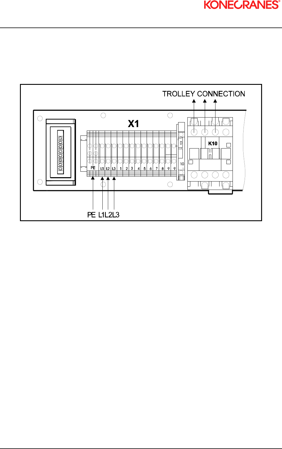
2.6 Three Phase Power Connections
Figure 2. Three Phase Control Box Power Connections
Minimum cable sections:
Power supply: AWG 16 (1.50 mm
2
)
Auxiliary current: AWG 18 (0.75 mm
2
)
Control box/hoist: AWG 18 (1.00 mm
2
)

XN10 I&M MANUAL/EN/11.30.2010
13/85
This document and the information contained herein, is the exclusive property of Konecranes Plc and represents a non-public, confidential and proprietary trade secret that may not
be reproduced, disclosed to third parties, altered or otherwise employed in any manner whatsoever without the express written consent of Konecranes Plc. Copyright © (2010)
Konecranes Plc. All rights reserved.
3 INITIAL START-UP
m
WARNING:
Before connecting power to hoist, check all “motion” buttons on pendant control
assembly to make sure that they operate freely without binding or sticking. Check
pendant cable and strain relief connection to ensure that they are not damaged.
3.1 General
Initial start-up procedures are as follows:
Read all attached WARNING tags and placards affixed to hoist.
Oil load chain generously over entire length of chain.
Make sure that load chain is not twisted. If so, untwist load chain before using.
Make sure fall stop is placed at least 6” [150 mm] from last chain link on free end.
Install chain container.
If furnished, make sure that trolley wheels have proper spacing in relation to beam flange. See
appropriate trolley manual for details.
Check direction of hook travel to make certain that it corresponds to respective control button that is
depressed. That is, does hook travel “UP” when UP BUTTON is depressed? If OK, go to section 3.3. If
not, proceed to section 3.2 for correcting direction of travel.
3.2 Correcting the Direction of Hook Travel
m
WARNING: DO NOT change control leads in pushbutton enclosure or at motor relays. DO
NOT change nameplates on pushbutton assembly. The upper/lower safety limit switch is
wired in series with “UP” control circuit as furnished from factory. Changing pushbutton
control leads or nameplates will prevent the upper safety travel limit switch from functioning
properly.
Reversing any two power leads of a three-phase AC motor will reverse the direction of rotation.
Reverse any two leads of a three-phase power at the main power source or at connections to motor.
Do not change internal wiring of hoist.
After changing two of the main power leads, recheck direction of rotation. Press “UP” button only. If
hook travel goes in “UP” direction, proceed to section 3.3. If not, redo section 3.2.

XN10 I&M MANUAL/EN/11.30.2010
14/85
This document and the information contained herein, is the exclusive property of Konecranes Plc and represents a non-public, confidential and proprietary trade secret that may not
be reproduced, disclosed to third parties, altered or otherwise employed in any manner whatsoever without the express written consent of Konecranes Plc. Copyright © (2010)
Konecranes Plc. All rights reserved.
3.3 Operational Checks – No Load
Check hoist motor brake function. Run empty load block up or down to check that load block does not
drift more than 1.0 inch [25mm]. If so, adjust brake as described in Section 7.3 of this manual.
Run empty load block down to check that fall stop (located on free end of load chain) makes proper
contact with upper / lower travel safety limit switch and that limit switch functions properly.
Run empty load block up to check that load block makes proper contact with upper / lower travel safety
limit switch and that limit switch functions properly.
Run empty load block up and down several times while checking for proper tracking of load chain.
3.4 Operational Checks – With Load
After completion of no-load operational tests, the user /owner should perform a full load test even though
each complete hoist is load tested at factory.
Lift a near capacity load about one (1) foot [30cm] above floor level. Check that the brake holds load.
Also, check stopping capability of brake when lifting to a stop and lowering to a stop.
Move trolley the full length of monorail or crane beam. Check for any binding of trolley wheels on flange
and/or interference at splice joints, hanger connections / bolts, etc.
Check contact with stops. Contact with stops SHALL only be made with trolley bumpers. Stops that are
designed to make contact with wheels SHALL NOT be used.

XN10 I&M MANUAL/EN/11.30.2010
15/85
This document and the information contained herein, is the exclusive property of Konecranes Plc and represents a non-public, confidential and proprietary trade secret that may not
be reproduced, disclosed to third parties, altered or otherwise employed in any manner whatsoever without the express written consent of Konecranes Plc. Copyright © (2010)
Konecranes Plc. All rights reserved.
4 HOIST OPERATION
m
WARNING: BEFORE PROCEEDING WITH THE NORMAL OPERATION OF THIS HOIST, THE
OPERATOR/(S) SHALL BE TRAINED IN ACCORDANCE WITH THE XN Electric Chain Hoist
Operator’s Manual AS SUPPLIED WITH THIS HOIST.
m
WARNING: FAILURE TO READ AND COMPLY WITH ANY ONE OF THE LIMITATIONS NOTED
IN THIS MANUAL AND THE XN Electric Chain Hoist Operator’s Manual FURNISHED WITH
THIS HOIST CAN RESULT IN PRODUCT FAILURE, SERIOUS BODILY INJURY OR DEATH,
AND / OR PROPERTY DAMAGE.
m
WARNING: REFER TO SECTION 1.0 OF THIS MANUAL FOR CONTACT INFORMATION IF
ADDITIONAL ASSISTANCE IS NEEDED.

XN10 I&M MANUAL/EN/11.30.2010
16/85
This document and the information contained herein, is the exclusive property of Konecranes Plc and represents a non-public, confidential and proprietary trade secret that may not
be reproduced, disclosed to third parties, altered or otherwise employed in any manner whatsoever without the express written consent of Konecranes Plc. Copyright © (2010)
Konecranes Plc. All rights reserved.
5 LOW HEADROOM TROLLEY
Figure 3. Low headroom trolley
5.1 Description – Technical Characteristics (low headroom trolley)
NOTE: The trolley you have just purchased must be used only with the nominal load indicated on the
rating plate.
NOTE: The trolley’s service life will depend upon the level of duty, the average operating time, the
number of starts and the maintenance applied to it.
5.1.1 Technical Characteristics
The low headroom trolley can be used for loads from 60 kg up to 5000 kg with all our electrical chain hoists.
It can be driven with an inverter drive unit or a dual or single speed unit.

XN10 I&M MANUAL/EN/11.30.2010
17/85
This document and the information contained herein, is the exclusive property of Konecranes Plc and represents a non-public, confidential and proprietary trade secret that may not
be reproduced, disclosed to third parties, altered or otherwise employed in any manner whatsoever without the express written consent of Konecranes Plc. Copyright © (2010)
Konecranes Plc. All rights reserved.
5.1.2 Environmental Data
Ambient temperature: -10°C to +40°C
Protection degree: IP55 as standard
Sound level: 70 decibels at 1 m
5.1.3 Optional equipment
Limit Switch: This cuts off the directional movement when the trolley reaches the end of its run.
Electric Actuation Device: This actuates the supply line; the slide block must not exceed the rolling
profile (A).
Brush: This allows for earthing, due to the brush rubbing on the profile element.
Raceway Stops: Not supplied: These must be fitted on the profile element, at the end of the trolley run.

XN10 I&M MANUAL/EN/11.30.2010
18/85
This document and the information contained herein, is the exclusive property of Konecranes Plc and represents a non-public, confidential and proprietary trade secret that may not
be reproduced, disclosed to third parties, altered or otherwise employed in any manner whatsoever without the express written consent of Konecranes Plc. Copyright © (2010)
Konecranes Plc. All rights reserved.
6 SWIVEL TROLLEY
6.1 Description – Technical Characteristics (swiveling trolley to 3.2
tons)
NOTE: The trolley you have just purchased must be used only with the nominal load indicated on the
rating plate.
NOTE: The trolley’s service life will depend on the level of duty, the average operating time, the
number of starts and the maintenance applied to it.
6.1.1 Technical Characteristics
Type 1 Type 2
30 Hz
≤1000 kg
100 Hz
>1000 kg
Fem Class H4 H4
IP IP55 IP55
Insulation class F F
Duty factor 40% 40%
Operating temperature -10°C, +40°C -10°C, +40°C
Power supply frequency 60 Hz 60 Hz
Standard speed 20/5 m/min 80/20 fpm 20/5 m/min 80/20 fpm
Default acceleration time (Deceleration time) 2.5 s 2.5 s
Thermal protection for motor Option Option
Thermal protection for frequency converter Std. Std.
Noise level 70 db 70 db

XN10 I&M MANUAL/EN/11.30.2010
19/85
This document and the information contained herein, is the exclusive property of Konecranes Plc and represents a non-public, confidential and proprietary trade secret that may not
be reproduced, disclosed to third parties, altered or otherwise employed in any manner whatsoever without the express written consent of Konecranes Plc. Copyright © (2010)
Konecranes Plc. All rights reserved.
6.2 Installation of Swivel Trolley
The service life of the trolley depends upon the way it is installed. The instructions in this manual must be
followed carefully for the installation, use and maintenance of the hoist. Any use contrary to these
instructions can be dangerous. Do not use hoist until this manual has been fully read and understood.
Always keep this manual near the hoist, available to the operator and the person in charge of maintenance.
Make sure that the safety rules are followed (harness, clearance of work areas, posting of instructions to be
followed in the area, etc.).
The Trolley can be mounted on any type of standard profile (see: setting of the flange width).
NOTE: Check the width of the runaway rail and adapt the spacing of the flanges of the trolley as
indicated by the tables.
Make sure:
That the profile is secured.
That the profile is suitable to the loads to be supported.
That the dimensions are compatible with the trolley that is to be installed.
That the electrical characteristics of the mains network conform to those of the motor.
Carry out:
1 – Disassembly of the trolley:
Remove the side plate on the counterweight side.
Position the trolley on the beam.
Refit the side plate.
(see: Tightening torques)
2 – Without disassembly of the trolley:
Install the trolley on the profile, by the end.
Fit the travel limit stops (not provided) at the end of the runway.
Check that the nuts are correctly tightened.
(see: Tightening torques)
After these checks, perform the following test with care:
1. Drive in one direction with the slow speed for a few seconds.
2. Accelerate up to the high speed and keep the high speed for 5-10 seconds.
3. Follow the same procedure in the other direction.
4. If the trolley drives in the wrong direction, swap the cables (blue and white) of the motor or the wires on
D1 and D2.
5. Check the function of the slow down and end limit switches.

XN10 I&M MANUAL/EN/11.30.2010
20/85
This document and the information contained herein, is the exclusive property of Konecranes Plc and represents a non-public, confidential and proprietary trade secret that may not
be reproduced, disclosed to third parties, altered or otherwise employed in any manner whatsoever without the express written consent of Konecranes Plc. Copyright © (2010)
Konecranes Plc. All rights reserved.
Figure 4. Drive wheel and idler wheel/side plates
Adjust drive wheel and idler wheel/side plates as shown above.
6.3 Electric Swivel Trolley
Figure 5. Electric swivel trolley
Table 1. Electric swivel trolley
HOIST TYPE SWIVELING
TROLLEY
TYPE
CAPACITY NUMBER OF
WHEELS
WHEEL
DIAMETER
MOTOR TYPE
C05 SWIV32 0 – 1 ton 4 100 2 x TMU 1 (35
Hz)
C10 SWIV32 0 – 2 tons 4 100 2 x TMU 2 (100
Hz)
C16-20-25 SWIV32 0 – 3.2 tons 4 100 2 x TMU 2 (100
Hz)

XN10 I&M MANUAL/EN/11.30.2010
21/85
This document and the information contained herein, is the exclusive property of Konecranes Plc and represents a non-public, confidential and proprietary trade secret that may not
be reproduced, disclosed to third parties, altered or otherwise employed in any manner whatsoever without the express written consent of Konecranes Plc. Copyright © (2010)
Konecranes Plc. All rights reserved.
6.3.1 Swiveling trolley (3.2 tons)
Figure 6. Swiveling trolley (3.2 tons)
- CAPACITY MAX 3.2 TONS (3200 KG)
- RAY OF CURVE MINI 2.6 FEET
6.3.2 Swiveling trolley (3.2 to 5.0 tons) (NOT LOCALLY AVAILABLE)
Figure 7. Swiveling trolley (3.2 to 5.0 tons)
- CAPACITY MAX 3.2 TO 5 TONS (3200 TO 5000 KG)
- RAY OF CURVE MINI 3.9 FEET

XN10 I&M MANUAL/EN/11.30.2010
22/85
This document and the information contained herein, is the exclusive property of Konecranes Plc and represents a non-public, confidential and proprietary trade secret that may not
be reproduced, disclosed to third parties, altered or otherwise employed in any manner whatsoever without the express written consent of Konecranes Plc. Copyright © (2010)
Konecranes Plc. All rights reserved.
6.3.3 Procedure to adjust swivel trolley guide rollers
1. Loosen nut “A” (8 plcs).
2. Adjust guide rollers the maximum distance away from beam.
3. Place swivel trolley on beam.
4. Move trolley to curve section of beam.
5. Adjust guide rollers allowing approximately 3/16” (4-5 mm) clearance per side using screw “B.”
6. Tighten nut “A” (8 plcs).
Figure 8. Swivel trolley guide rollers
NOTE: Adjustments should be made with swivel trolley in radius of monorail.

XN10 I&M MANUAL/EN/11.30.2010
23/85
This document and the information contained herein, is the exclusive property of Konecranes Plc and represents a non-public, confidential and proprietary trade secret that may not
be reproduced, disclosed to third parties, altered or otherwise employed in any manner whatsoever without the express written consent of Konecranes Plc. Copyright © (2010)
Konecranes Plc. All rights reserved.
7 MAINTENANCE
7.1 Basic Hoist Construction
Figure 9. Basic Hoist Components
1. LOAD BLOCK ASSEMBLY (2-FALL SHOWN)
2. LOAD CHAIN
3. ELECTRICAL CONTROL ENCLOSURE
4. TOP HOOK
5. HOIST GEAR BOX ASSEMBLY
6. CHAIN CONTAINER & HARDWARE
7. HOIST BODY / MOTOR
8. LOAD HOOK SAFETY LATCH
9. FASTENER
10. PIN
7.2 Motor / Body
The hoist motors are designed to provide dependable hoisting service. The standard motors are enclosed
for IP55 rated protection against normal hazards of dust and moisture. The motor bearings are sealed and
do not require further greasing.
The hoist body is constructed of aluminum and requires no maintenance. Remove from service and replace
the hoist body if damaged.

XN10 I&M MANUAL/EN/11.30.2010
24/85
This document and the information contained herein, is the exclusive property of Konecranes Plc and represents a non-public, confidential and proprietary trade secret that may not
be reproduced, disclosed to third parties, altered or otherwise employed in any manner whatsoever without the express written consent of Konecranes Plc. Copyright © (2010)
Konecranes Plc. All rights reserved.
7.3 Hoist Motor Brake and Load-Limiting Device
The hoisting motor is equipped with a D.C. electromagnetic disc brake. The brake brings the load to a
smooth and quick stop and holds the load when the motor is not energized. An energized coil releases the
hoist brake to allow the hoisting motor to run freely when in use.
The load-limiting device is a slip clutch and it is integrated into the design of the hoist motor brake. Even if
the clutch slips, once power is removed, the brake will engage to stop and hold the load.
7.4 Slip Clutch Adjustment
Figure 10. Slip Clutch Adjustment

XN10 I&M MANUAL/EN/11.30.2010
25/85
This document and the information contained herein, is the exclusive property of Konecranes Plc and represents a non-public, confidential and proprietary trade secret that may not
be reproduced, disclosed to third parties, altered or otherwise employed in any manner whatsoever without the express written consent of Konecranes Plc. Copyright © (2010)
Konecranes Plc. All rights reserved.
m
CAUTION:
SEE Figure 10.
Make sure the motor is not running before placing tool on the nut (ITEM 5) to adjust
it. Do not touch any moving components.
The slip-clutch generates heat when slipping. ITEMS 3 & 4 absorb this heat. When
these items become too hot, clutch adjustment may be difficult due to unstable
behavior of friction surfaces. If this happens, allow brake & clutch assembly to cool
before trying to re-adjust slip-clutch.
Decreasing torque too much when adjusting slip-clutch will allow a suspended load
to free-fall when trying to lift. If this occurs, release the motion button and the brake
will engage to stop and hold the load.
7.4.1 Slip Clutch Adjustment after Installation
1. Hook a load of at least 110 percent but not more than 125 percent of nameplate capacity.
2. Remove plastic cap from inspection hole in brake cover.
3. Raise load at slow speed and fast speed to test slip clutch operation.
4. Insert a socket (13mm) through inspection hole, and slide it over nut (ITEM 5 - Figure 10).
5. Turn nut in required direction:
Turn nut clockwise to increase the torque.
Turn nut counterclockwise to decrease the torque.
6. Repeat steps 3 and 4 until load can be barely lifted in fast speed. CAUTION: DO NOT OVERHEAT.
If overheated, clutch may not adjust due to instability of friction surfaces.
7. Once adjustment is completed, install plastic cap.
8. Check function of clutch at 100 percent of nameplate-capacity while in fast speed.
NOTICE:
The slip clutch / Torque L
imiter is a safety device to prevent overloading of the hoist.
This device is not intended for use as means to measure the weight of load being
lifted.

XN10 I&M MANUAL/EN/11.30.2010
26/85
This document and the information contained herein, is the exclusive property of Konecranes Plc and represents a non-public, confidential and proprietary trade secret that may not
be reproduced, disclosed to third parties, altered or otherwise employed in any manner whatsoever without the express written consent of Konecranes Plc. Copyright © (2010)
Konecranes Plc. All rights reserved.
7.4.2 Hoist Motor Brake Adjustment
Figure 11. Cross Section of Hoist Motor Brake
If maximum air gap of brake has been reached or will be exceeded before next inspection, readjust air gap.
Minimum air gap Maximum air gap
X = 0.008” [ 0.2 mm ] X = 0.020” [ 0.5 mm ]
Before adjusting brake, remove load. Per ANSI Z244.1, lockout and tag main disconnect switch in de-
energized position. Follow other maintenance procedures outlined in this manual and ASME B30.16.
1. Remove brake cover and gasket.
2. With a feeler gauge, check three (3) places near each mounting bolts to measure air gap ( X )
between brake thrust disc (item 7) and coil (item 6).
3. To adjust air gap use a 0.008” feeler gauge and proceed as follows:
A. Slightly loosen motor brake mounting screws (item 10), so that adjusting nut (item 11) still
touches brake housing.
B. To reduce air gap, turn adjusting nut (item 11) counterclockwise.
C. To increase air gap, turn adjusting nut (item 11) clockwise.
D. Check air gap after adjusting the brake. Make certain the (3) screws (item 10) are tightened per
Torque specification. See Section 8.4.
4. Check brake operation. Run load block up and down several times without a load to test operation of
brake. Then, lift a capacity load about one foot above floor, stop, and check that brake holds load.
5. Install gasket and brake cover.

XN10 I&M MANUAL/EN/11.30.2010
27/85
This document and the information contained herein, is the exclusive property of Konecranes Plc and represents a non-public, confidential and proprietary trade secret that may not
be reproduced, disclosed to third parties, altered or otherwise employed in any manner whatsoever without the express written consent of Konecranes Plc. Copyright © (2010)
Konecranes Plc. All rights reserved.
7.4.3 Replacement Criteria for Motor Brakes
Table 2. Replacement criteria for motor brakes
Figure 12. Replacement criteria for motor brakes
XN 01 / 05 / 10 MODELS
XN 16 / 20 / 25 MODELS
THICKNESS AS NEW REPLACE WHEN
XN 01 0.260 inches (6.6 mm) 0.220 inches (5.6 mm)
XN 05 0.370 inches (9.4 mm) 0.330 inches (8.4 mm)
XN 10 0.055 inches (1.4 mm) 0.016 inches (0.4 mm)
XN 16 0.406 inches (10.3 mm) 0.366 inches (9.3 mm)
XN 20 0.406 inches (10.3 mm) 0.366 inches (9.3 mm)
XN 25 0.406 inches (10.3 mm) 0.366 inches (9.3 mm)

XN10 I&M MANUAL/EN/11.30.2010
28/85
This document and the information contained herein, is the exclusive property of Konecranes Plc and represents a non-public, confidential and proprietary trade secret that may not
be reproduced, disclosed to third parties, altered or otherwise employed in any manner whatsoever without the express written consent of Konecranes Plc. Copyright © (2010)
Konecranes Plc. All rights reserved.
7.5 Load Chain
7.5.1 General
m
CAUTION: A hoist SHALL NEVER be used if the load chain shows any evidence of
mechanical damage or excessive wear. Never use the load chain as a sling. Use only
original equipment chain as supplied by a factory authorized source. Improper load chain
storage or installation can render the load chain unusable prior to the first lift.
7.5.2 Maintenance Inspection
A qualified person SHALL be designated to routinely conduct an in-depth inspection of the load chain (See
Section 8 – Preventative Maintenance for schedule recommendations). This designated person SHALL
inspect load chain using good judgment in evaluating the remaining service life. Any deterioration of load
chain resulting in appreciable loss of original strength SHALL be noted and evaluated.
An in-depth inspection SHALL include a written record that is dated and signed by the inspector.

XN10 I&M MANUAL/EN/11.30.2010
29/85
This document and the information contained herein, is the exclusive property of Konecranes Plc and represents a non-public, confidential and proprietary trade secret that may not
be reproduced, disclosed to third parties, altered or otherwise employed in any manner whatsoever without the express written consent of Konecranes Plc. Copyright © (2010)
Konecranes Plc. All rights reserved.
Figure 13. Chain Dimensions
11 t
t
t
P25004
Ød
Measure the following chain dimensions at several points on chain: (Figure 13)
Dimensions of one link ( d x t ) where, d = diameter and t = pitch
Length over 11 links ( 11 t )
Replace load chain if any one of these dimensions exceeds maximum allowed wear.
Maximum allowed wear:
Minimum link diameter allowed (d): 0.240” [6.1 mm] MINIMUM
Maximum pitch allowed (t): 0.736” [18.7 mm] MAXIMUM
Maximum length allowed (11t): 7.862” [199.7 mm] MAXIMUM
NOTE: If load chain needs replaced, then inspect chain guide and chain (load) wheel
on hoist and idler sprocket in 2-fall load block for excessive wear. A chain sprocket
showing evidence of scored pockets or sharp edges generated from wear SHALL be
replaced. A worn chain sprocket or idler sprocket can greatly reduce the life of load
chain.

XN10 I&M MANUAL/EN/11.30.2010
30/85
This document and the information contained herein, is the exclusive property of Konecranes Plc and represents a non-public, confidential and proprietary trade secret that may not
be reproduced, disclosed to third parties, altered or otherwise employed in any manner whatsoever without the express written consent of Konecranes Plc. Copyright © (2010)
Konecranes Plc. All rights reserved.
7.5.3 Load Chain Specifications (see Figure 13)
Chain type: Standard Load Chain
Diameter (d) / pitch (t): 0.268” (6.8 mm) /0.701” (17.8 mm)
Class: DAT
Grade: H8S or HE G80 RAS
Maximum working stress: 19,595 lbs/in
2
(135.1 N/mm
2
)
Hardened surface: 580 or 700 HV (Vickers Hardness)
Thickness: 0.006” (0.14 mm) to 0.011” (0.28 mm)
Standard: DIN 5684 - 8
Marking (10 x t): 1 or 16
H 8 S or A 8
Maximum working load, 1 fall: 2200 lbs. (1000 kg)
Breaking load: 13,062.05 psf (58.1 kN)
Maximum breaking stress: 116 030 lbs/in
2
(800 N/mm
2
)
Total braking elongation: >10% min.
Weight for 100 links: 2.38 lbs. (1.08 kg)
7.5.4 Removing the Load Chain
1-FALL CHAIN
1. Remove load from hook block assembly.
2. Remove load block assembly from load chain. Some disassembly of 1-fall load block is required.
3. Attach the chain insert tool to the end of bottom block end of the chain.
4. Run hoist in “UP” direction until all of chain is in container. Stop the hoist with the insertion tool
remaining in the hoist ready for the new chain.
5. Remove chain container with all of old chain in chain container.
6. Remove fall stop from old chain and save for use with new chain.
2-FALL CHAIN
1. Remove load from hook block assembly.
2. Run hoist in “UP” direction until hook block assembly is about 1.0 foot [30cm] from hoist body.
3. Unfasten load chain from chain anchor mounted on hoist body.
4. Remove load block assembly from load chain by allowing chain to run through it. Attach the chain
insertion tool to the bottom block end of the chain.
5. Run hoist in “UP” direction until all of the chain is in the container. Stop the hoist with the insertion tool
remaining in the hoist ready for the new chain.
6. Remove chain container with old chain.
7. Remove fall stop from old chain and save for use with new chain.

XN10 I&M MANUAL/EN/11.30.2010
31/85
This document and the information contained herein, is the exclusive property of Konecranes Plc and represents a non-public, confidential and proprietary trade secret that may not
be reproduced, disclosed to third parties, altered or otherwise employed in any manner whatsoever without the express written consent of Konecranes Plc. Copyright © (2010)
Konecranes Plc. All rights reserved.
7.5.5 Installing the Load Chain
Figure 14. Chain installation
Figure 15. Chain orientation
1-FALL CHAIN INSTALLATION
1. Attach last link of chain onto hook of CHAIN INSERTION TOOL (item 1, Figure 14).
2. If the insertion tool is not in the hoist (removal procedure), insert other end of CHAIN INSERTION TOOL
into chain opening closest to chain container side.
m
CAUTION: Make sure the chain weld on chain link faces inward toward chain wheel
pocket on hoist load sprocket. See Figure 15.
3. Run hoist “DOWN” in slow speed to feed chain through chain sprocket and out other side.
4. Attach fall stop at least 6.0 inches [150 mm] from end of chain (chain container side). Attach load block
assembly on other end of load chain. Refer to Figure 15 for details.
5. Make sure that load chain is not twisted or deformed.
6. Attach chain container.

XN10 I&M MANUAL/EN/11.30.2010
32/85
This document and the information contained herein, is the exclusive property of Konecranes Plc and represents a non-public, confidential and proprietary trade secret that may not
be reproduced, disclosed to third parties, altered or otherwise employed in any manner whatsoever without the express written consent of Konecranes Plc. Copyright © (2010)
Konecranes Plc. All rights reserved.
2-FALL CHAIN INSTALLATION
1. If the chain insertion tool is not in the hoist (removal procedure), attach last link of chain onto hook of
CHAIN INSERTION TOOL (item 1, Figure 14).
2. Insert other end of CHAIN INSERTION TOOL into chain opening closest to chain container.
m
CAUTION: For a 2-Fall load block assembly, make sure the chain weld on chain link
faces inward toward chain wheel pocket on hoist and away from idler sprocket of
hook block assembly. See figure 5.6. Follow steps outlined below:
3. Run hoist in slow speed to feed chain through chain sprocket. Continue running until about 2.0 feet
[60cm] of chain is available out the other side.
4. Slide chain onto idler sprocket of load block making sure not to twist chain while inserting it. Link
weld must face away from idler sprocket on load block assembly.
5. Attach chain anchor and chain to hoist body. Tighten chain anchor bolts per recommended torque
settings in Section 8.4.
6. Attach fall stop 6.0 inches [150 mm] from end of chain (chain container side). See Figure 16 for
details.
7. Make sure that chain is not twisted or kinked.
8. Attach chain container
After chain installation:
1. Without a load, run chain up and down a few times to make sure load chain is not twisted. If so,
remove chain twist.
2. Lubricate load chain.

XN10 I&M MANUAL/EN/11.30.2010
33/85
This document and the information contained herein, is the exclusive property of Konecranes Plc and represents a non-public, confidential and proprietary trade secret that may not
be reproduced, disclosed to third parties, altered or otherwise employed in any manner whatsoever without the express written consent of Konecranes Plc. Copyright © (2010)
Konecranes Plc. All rights reserved.
7.6 Fall Stop Assembly
7.6.1 General
The slack fall stop is a safety stop, not a functional stop. The fall stop must be located at least six
(6.0) inches [150mm] from end of last chain link.
Figure 16. Cross Section of Slack Fall Stop
6''
1
2
3
3
7.6.2 Removing fall stop (Figure 16)
1. Remove cotter pin (item 1).
2. Slide up the tube (item 2).
3. Remove the two fall stop halves (item 3).
4. Slide tube (item 2) off load chain.
7.6.3 Fall Stop Installation (Figure 16)
1. Slide tube (item 2) onto load chain.
2. Position two fall stop halves (item 3) on a chain link so that the fall stop will be at least 6 inches [150mm]
from end of load chain.
3. Slide tube (item 2) down over two fall stop halves (item 3).
4. Insert and secure cotter pin (item 1).

XN10 I&M MANUAL/EN/11.30.2010
34/85
This document and the information contained herein, is the exclusive property of Konecranes Plc and represents a non-public, confidential and proprietary trade secret that may not
be reproduced, disclosed to third parties, altered or otherwise employed in any manner whatsoever without the express written consent of Konecranes Plc. Copyright © (2010)
Konecranes Plc. All rights reserved.
7.7 Chain Container
Figure 17. Chain Container Installation
m
CAUTION: Chain container must be installed for effective operation of travel limit switch.
7.7.1 Removing Chain Container (Figure 17)
1. Remove cotter pin (item 5) from end of pin (item 3).
2. Pull pin (item 3) out while supporting chain container (item 2).
3. Remove chain container (item 2).
7.7.2 Installing Chain Container (Figure 17)
1. Insert load chain into chain container (item 2). Position chain container (item 2) onto hoist mounting
bracket (item 1).
2. Align holes and insert pin (item 3) through container (item 2) and hoist mounting bracket (item 1).
3. Place washer (item 4) onto pin (item 3).
4. Insert and secure cotter pin (item 5).

XN10 I&M MANUAL/EN/11.30.2010
35/85
This document and the information contained herein, is the exclusive property of Konecranes Plc and represents a non-public, confidential and proprietary trade secret that may not
be reproduced, disclosed to third parties, altered or otherwise employed in any manner whatsoever without the express written consent of Konecranes Plc. Copyright © (2010)
Konecranes Plc. All rights reserved.
7.8 Vinyl Chain Bag (optional)
Figure 18. Vinyl Chain Bag Installation Connection
7.8.1 Installing Vinyl Chain Bag (Figure 18)
1. Insert load chain into vinyl chain bag. Position vinyl chain bag onto hoist mounting bracket.
2. Align holes and insert cotter pin through appropriate bag connection holes for the specific model.
2.1. Use Item 1 connection holes for the Model 10 hoist.
3. Place washer onto pin.
4. Insert and secure cotter pin.

XN10 I&M MANUAL/EN/11.30.2010
36/85
This document and the information contained herein, is the exclusive property of Konecranes Plc and represents a non-public, confidential and proprietary trade secret that may not
be reproduced, disclosed to third parties, altered or otherwise employed in any manner whatsoever without the express written consent of Konecranes Plc. Copyright © (2010)
Konecranes Plc. All rights reserved.
7.9 Limit Switches
7.9.1 Upper and Lower Travel Safety Limit Switch
The Upper and Lower Travel Limit Switch is an automatic reset type switch and connected to the control
circuit. The switch housing is recessed into the underside of hoist body.
The upper and lower limit switches are emergency protection devices and are not to be used as a continuous
stop.
The hook block activates the upper limit switch as it contacts the limit switch that is located on bottom side of
hoist body. Once the switch is activated, the “UP” circuit is opened. The fall stop activates the lower limit
switch when hook block is lowered to its lowest travel position. The limit switch is activated and opens the
“down” circuit.
The lower limit position is adjustable between the lowest travel and maximum lift. It is adjusted by
repositioning the fall stop assembly on free end of load chain. The fall stop SHALL always be located at
least 6 inches [150mm] from end of last chain link. The upper limit position is adjustable only when an
additional fall stop assembly is added between the hook block assembly and the hoist body.

XN10 I&M MANUAL/EN/11.30.2010
37/85
This document and the information contained herein, is the exclusive property of Konecranes Plc and represents a non-public, confidential and proprietary trade secret that may not
be reproduced, disclosed to third parties, altered or otherwise employed in any manner whatsoever without the express written consent of Konecranes Plc. Copyright © (2010)
Konecranes Plc. All rights reserved.
7.9.2 Upper and Lower Rotary Travel Limit Switch (Optional Only on 3-Phase units)
The rotary limit switch is adjustable and provides over-travel protection for the upper and lower limits of hoist
travel. The limit switch is connected to the control circuit.
Note: Not available on Single Phase – 115 Volt Models
Note: Rotary limit switch assembly cannot be added to a Hoist. The Hoist must have
the rotary limit switch assembly provided at time of initial production.
Adjustment
The position of the air-gap between the two discs (red – gray) determines the stopping place. This position
can be found by gently turning the two discs. The length of air gap determines length of reset play in
opposite direction.
Figure 19. Air Gap Adjustment
To reset the rotary limit once it has tripped, the load block assembly must travel approximately 11” [27cm] in
opposite direction.

XN10 I&M MANUAL/EN/11.30.2010
38/85
This document and the information contained herein, is the exclusive property of Konecranes Plc and represents a non-public, confidential and proprietary trade secret that may not
be reproduced, disclosed to third parties, altered or otherwise employed in any manner whatsoever without the express written consent of Konecranes Plc. Copyright © (2010)
Konecranes Plc. All rights reserved.
7.10 Hooks
7.10.1 General
Check hooks for deformation or cracks. Hooks must be replaced if throat opening has increased by more
than 15%, or if throat opening has more than 10-degree twist from plane of straight hook.
Figure 20. Measuring Hook Deformation
Due to many types and sizes of hooks that can be furnished and/or specified by the user / owner, it is
recommended that user / owner measure the actual throat opening of hook as originally furnished. See
Figure 20. Record the throat dimension on above sketch. Retain as a permanent record. This record can
then be used for determining when hook must be replaced due to deformation or excessive throat opening.
m
CAUTION: Abuse or overloading of hoist is indicated when any hook is twisted or has a
throat opening in excess of normal. Other load bearing components SHALL be checked for
damage.
m
CAUTION: Safety latches SHALL be replaced if missing, bent, or broken.
m
CAUTION: A safety latch SHALL function properly at all times.
m
CAUTION: Repairing hooks by welding or reshaping is strictly forbidden.

XN10 I&M MANUAL/EN/11.30.2010
39/85
This document and the information contained herein, is the exclusive property of Konecranes Plc and represents a non-public, confidential and proprietary trade secret that may not
be reproduced, disclosed to third parties, altered or otherwise employed in any manner whatsoever without the express written consent of Konecranes Plc. Copyright © (2010)
Konecranes Plc. All rights reserved.
7.10.2 Hook Inspection
The wear on the top hook and the load hook SHALL be checked routinely. Measure the throat
opening (dimension
a
2 - FIGURE 21). If the throat opening exceeds the maximum opening allowed,
replace the hook. Damaged safety latches shall be replaced immediately.
Figure 21. Hook Dimensions
LOAD
CAPACITY
(LBS)
TEST
LOAD FALLS
MINIMUM
FAILURE
LOAD
CLASS
1389 2778 1 8752 025T
2205 4409 1 11023 025T
2756 5512 2 17361 05T
4409 8818 2 22046 05T
HOOK DIMENSIONS – INCHES
ØM Øa1 a2 a3 b1 b2 e1 h1 h2 t1 t2
0.630
1.417 1.024 1.614 0.866 0.748 3.780 1.102 0.945 1.496 0.512
0.630
1.417 1.024 1.614 0.866 0.748 3.780 1.102 0.945 1.496 0.512
0.787
1.693 1.339 1.929 1.142 0.945 4.134 1.457 1.221 1.496 0.551
0.787
1.693 1.339 1.929 1.142 0.945 4.134 1.457 1.221 1.496 0.551
Initial Dimension – a2 Max. Allowed Dimension Mark: ISO 2766
1.024 inches 1.178 inches maximum DIN Model Number: 15401
1.339 inches 1.540 inches maximum DIN 15400 Class: T
DIN 15401 Material: 35 CD 4

XN10 I&M MANUAL/EN/11.30.2010
40/85
This document and the information contained herein, is the exclusive property of Konecranes Plc and represents a non-public, confidential and proprietary trade secret that may not
be reproduced, disclosed to third parties, altered or otherwise employed in any manner whatsoever without the express written consent of Konecranes Plc. Copyright © (2010)
Konecranes Plc. All rights reserved.
7.10.3 Top Hook
Figure 22. Top Hook Orientation
m
CAUTION: Before removing Top Hook, de-energize the power to the hoist per ANSI Z244.1
and make certain that any load is removed from the load hook. Also support the total
weight of the hoist, including chain, prior to removing the Top Hook.
Removing Top Hook
1. Place hoist on workbench. Protect limit switches on bottom side of hoist.
2. Remove screw and locking plate.
3. Pull pins out and remove hook.
m
CAUTION: Proper installation of top hook is critical for hoist balance.
Installing Top Hook
1. Place hoist on workbench. Protect limit switches on bottom side of hoist.
2. Determine number of chain falls: 1-fall or 2-fall. Reference Figure 22.
3. Select proper placement of top hook relative to number of chain falls:
If 1-fall, align top hook so that tip of hook faces toward chain container.
If 2-fall, align top hook so that tip of hook faces away from chain container.
4. Place hook into the slot on hoist body. Verify that top hook saddle and load hook saddle are in line with
each other. Install pins and locking plate. Secure locking plate with screw.
CHAIN
CONTAINER
BRACKET
XN10 I&M MANUAL/EN/11.30.2010
41/85
This document and the information contained herein, is the exclusive property of Konecranes Plc and represents a non-public, confidential and proprietary trade secret that may not
be reproduced, disclosed to third parties, altered or otherwise employed in any manner whatsoever without the express written consent of Konecranes Plc. Copyright © (2010)
Konecranes Plc. All rights reserved.
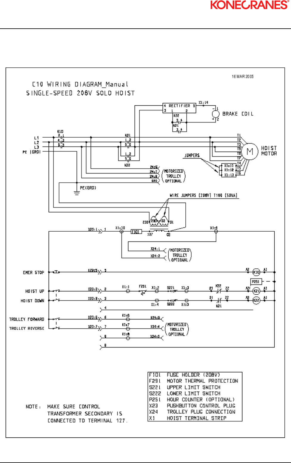
7.11 Control Changes and Fuses
The layouts and wiring diagrams found within this section are for standard hoist controls. Single speed
hoists are available for 208, 230, and 460 volt three-phase power supplies; but not for 575 volts.
Two-speed hoists are available for 208, 230, 460, and 575 volt, three-phase power supplies. The two-speed
hoists can only be connected to the specified voltage on the hoist serial plate.
Control Circuit Fuse
The control circuit fuse holder is located on terminal strip X1. The fuse holder top flips up to facilitate
changing a defective fuse.
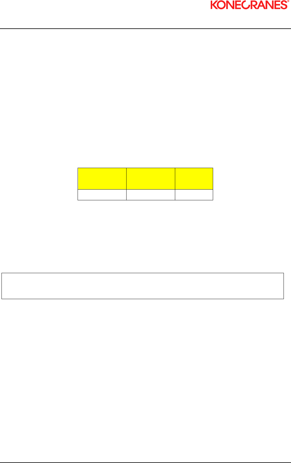
Table 3. Control Circuit Fuse
POWER
CONTROL FUSE
SUPPLY VOLTAGE SIZE
3 – PHASE 115 VAC 630 mA
Three-phase Single-speed Voltage Changes:
The Single-speed models may be changed to accommodate 208/230/460 volt power supplies. A hoist
supplied with a motorized trolley CANNOT be reconnected.
Note: Motorized trolley drives are not voltage re-connectable. Consult the
motorized trolley manual if a voltage change over is required.
Refer to the respective Single-speed wiring diagrams and make the following connections for the following
voltages:

XN10 I&M MANUAL/EN/11.30.2010
42/85
This document and the information contained herein, is the exclusive property of Konecranes Plc and represents a non-public, confidential and proprietary trade secret that may not
be reproduced, disclosed to third parties, altered or otherwise employed in any manner whatsoever without the express written consent of Konecranes Plc. Copyright © (2010)
Konecranes Plc. All rights reserved.
208 / 230 VOLT (SEE 208/230 VOLT SINGLE SPEED CONTROL LAYOUT & WIRING DIAGRAM)
1. Connect motor brake lead (-) to terminal strip X1 terminal 14. Connect (+) to K21 terminal 4.
2. Motor Leads:
a. T1 & T7 connect to main line contactor K10 terminal 1.
b. T2 & T8 connect to DOWN contactor K22 terminal 2.
c. T3 & T9 connect to DOWN contactor K22 terminal 6.
d. T4 connect to terminal strip X1 terminal 11.
e. T5 connect to terminal strip X1 terminal 12.
f. T6 connect to terminal strip X1 terminal 13.
g. Jumper wires on terminal strip X1 to connect terminals 11, 12, and 13.
3. Control transformer connections:
a. Jumper connections terminals 230 to 230 and terminals 01 to 02. See control panel layouts and
wiring diagrams.
460 VOLT (REFER TO 460 VOLT SINGLE SPEED WIRING DIAGRAM)
1. Connect motor brake lead (-) to contactor K21 terminal 2.
2. Motor leads:
a. T1 connect to main line contactor K10 terminal 1.
b. T2 connect to DOWN contactor K22 terminal 2.
c. T3 connect to DOWN contactor K22 terminal 6.
d. T4 & T7 connect to terminal strip X1 terminal 11.
e. T5 & T8 connect to terminal strip X1 terminal 12.
f. T6 & T9 connect to terminal strip X1 terminal 13.
3. Control transformer connections:
a. Jumper connections for 460 volt (see wiring diagram).
Table 4. Wiring Diagram
Power & Motor
Supply
Pendant Plug X23
Description
Pin
No:
Tag strip X1
Terminal No:
Control Panel
Description
Plug Pin
No:
L1 Hoist power supply Common 1 10 SD: low speed 2
L2 Hoist power supply Hoist UP 2 1 Hoist UP
L3 Hoist power supply Hoist DOWN 3 4 Hoist DOWN
K21-2 + brake Hoist FAST 4 6 D2: Trolley FWD 5
K21-4 - brake Emergency stop 5 7 D1: Trolley REV 4
K10-1 T1, T7 motor supply Trolley FWD 6 8 F: Trolley Fast 3
K22-4 T3, T9 motor supply Trolley REV 7 9 Control voltage 1
K22-6 T2, T8 motor supply Trolley FAST 8 1-2 Thermal protection
X1-11 T4 motor supply 2-3 Upper limit switch
X1-12 T5 motor supply 4-5 Lower limit switch
X1-13 T6 motor supply K10 Mainline contactor
Ground Terminals
Description
K21 Hoist UP contactor
PE Motor K22 Hoist DOWN
Contactor
PE Control panel K25 Hoist FAST
PE Trolley connection T100 Control Transformer
PE Power supply 9 Counter (option)
K22-22 Counter (option)
F100 630 mA
XN10 I&M MANUAL/EN/11.30.2010
43/85
This document and the information contained herein, is the exclusive property of Konecranes Plc and represents a non-public, confidential and proprietary trade secret that may not
be reproduced, disclosed to third parties, altered or otherwise employed in any manner whatsoever without the express written consent of Konecranes Plc. Copyright © (2010)
Konecranes Plc. All rights reserved.
7.12 Single-Speed Solo Hoist – 208 Volt Wiring Diagram
Figure 23. Single-speed solo hoist – 208 volt wiring diagram
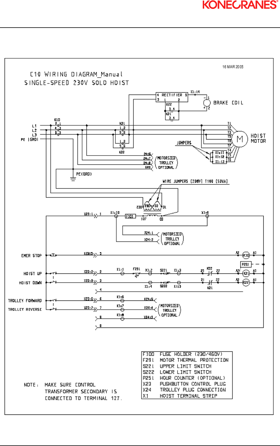
XN10 I&M MANUAL/EN/11.30.2010
44/85
This document and the information contained herein, is the exclusive property of Konecranes Plc and represents a non-public, confidential and proprietary trade secret that may not
be reproduced, disclosed to third parties, altered or otherwise employed in any manner whatsoever without the express written consent of Konecranes Plc. Copyright © (2010)
Konecranes Plc. All rights reserved.
7.13 Single-Speed Solo Hoist – 230 Volt Wiring Diagram
Figure 24. Single-speed solo hoist – 230 volt wiring diagram

XN10 I&M MANUAL/EN/11.30.2010
45/85
This document and the information contained herein, is the exclusive property of Konecranes Plc and represents a non-public, confidential and proprietary trade secret that may not
be reproduced, disclosed to third parties, altered or otherwise employed in any manner whatsoever without the express written consent of Konecranes Plc. Copyright © (2010)
Konecranes Plc. All rights reserved.
7.14 Single-speed Solo Hoist – 460 Volt Wiring Diagram
Figure 25. Single-speed solo hoist – 460 volt wiring diagram

XN10 I&M MANUAL/EN/11.30.2010
46/85
This document and the information contained herein, is the exclusive property of Konecranes Plc and represents a non-public, confidential and proprietary trade secret that may not
be reproduced, disclosed to third parties, altered or otherwise employed in any manner whatsoever without the express written consent of Konecranes Plc. Copyright © (2010)
Konecranes Plc. All rights reserved.
7.15 Two-Speed Solo Hoist - 208 Volt Wiring Diagram
Figure 26. Two-speed solo hoist – 208 volt wiring diagram

XN10 I&M MANUAL/EN/11.30.2010
47/85
This document and the information contained herein, is the exclusive property of Konecranes Plc and represents a non-public, confidential and proprietary trade secret that may not
be reproduced, disclosed to third parties, altered or otherwise employed in any manner whatsoever without the express written consent of Konecranes Plc. Copyright © (2010)
Konecranes Plc. All rights reserved.
7.16 Two-Speed Solo Hoist - 230 Volt Wiring Diagram
Figure 27. Two-speed solo hoist – 230 volt wiring diagram

XN10 I&M MANUAL/EN/11.30.2010
48/85
This document and the information contained herein, is the exclusive property of Konecranes Plc and represents a non-public, confidential and proprietary trade secret that may not
be reproduced, disclosed to third parties, altered or otherwise employed in any manner whatsoever without the express written consent of Konecranes Plc. Copyright © (2010)
Konecranes Plc. All rights reserved.
7.17 Two-Speed Solo Hoist - 460 Volt Wiring Diagram
Figure 28. Two-speed solo hoist – 460 volt wiring diagram
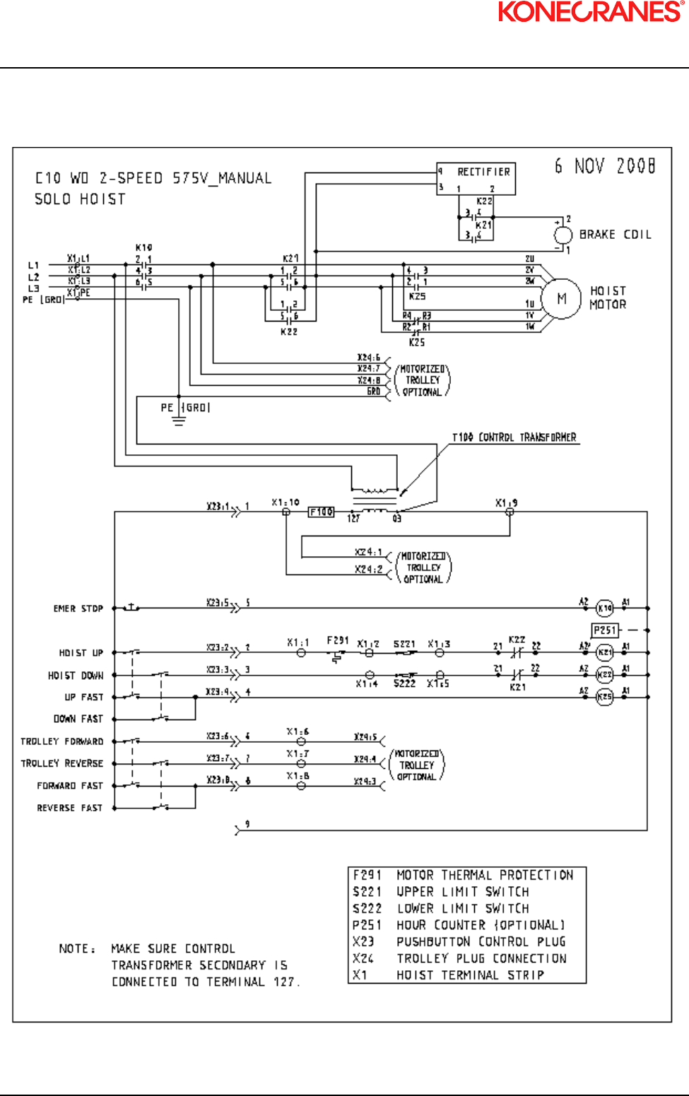
XN10 I&M MANUAL/EN/11.30.2010
49/85
This document and the information contained herein, is the exclusive property of Konecranes Plc and represents a non-public, confidential and proprietary trade secret that may not
be reproduced, disclosed to third parties, altered or otherwise employed in any manner whatsoever without the express written consent of Konecranes Plc. Copyright © (2010)
Konecranes Plc. All rights reserved.
7.18 Two-Speed Solo Hoist – 575 Volt Wiring Diagram
Figure 29. Two-speed solo hoist – 575 volt wiring diagram

XN10 I&M MANUAL/EN/11.30.2010
50/85
This document and the information contained herein, is the exclusive property of Konecranes Plc and represents a non-public, confidential and proprietary trade secret that may not
be reproduced, disclosed to third parties, altered or otherwise employed in any manner whatsoever without the express written consent of Konecranes Plc. Copyright © (2010)
Konecranes Plc. All rights reserved.
7.19 Single-Speed Hoist – Modular Crane – 208 Volt Diagram
Figure 30. Single-speed hoist – modular crane – 208 volt diagram

XN10 I&M MANUAL/EN/11.30.2010
51/85
This document and the information contained herein, is the exclusive property of Konecranes Plc and represents a non-public, confidential and proprietary trade secret that may not
be reproduced, disclosed to third parties, altered or otherwise employed in any manner whatsoever without the express written consent of Konecranes Plc. Copyright © (2010)
Konecranes Plc. All rights reserved.
7.20 Single-Speed Hoist – Modular Crane – 230 Volt Diagram
Figure 31. Single-speed hoist – modular crane – 230 volt diagram

XN10 I&M MANUAL/EN/11.30.2010
52/85
This document and the information contained herein, is the exclusive property of Konecranes Plc and represents a non-public, confidential and proprietary trade secret that may not
be reproduced, disclosed to third parties, altered or otherwise employed in any manner whatsoever without the express written consent of Konecranes Plc. Copyright © (2010)
Konecranes Plc. All rights reserved.
7.21 Single-Speed Hoist – Modular Crane – 460 Volt Diagram
Figure 32. Single-speed hoist – modular crane – 460 volt diagram

XN10 I&M MANUAL/EN/11.30.2010
53/85
This document and the information contained herein, is the exclusive property of Konecranes Plc and represents a non-public, confidential and proprietary trade secret that may not
be reproduced, disclosed to third parties, altered or otherwise employed in any manner whatsoever without the express written consent of Konecranes Plc. Copyright © (2010)
Konecranes Plc. All rights reserved.
7.22 Two-Speed Hoist – Modular Crane – 208 Volt Diagram
Figure 33. Two-speed hoist – modular crane – 208 volt diagram

XN10 I&M MANUAL/EN/11.30.2010
54/85
This document and the information contained herein, is the exclusive property of Konecranes Plc and represents a non-public, confidential and proprietary trade secret that may not
be reproduced, disclosed to third parties, altered or otherwise employed in any manner whatsoever without the express written consent of Konecranes Plc. Copyright © (2010)
Konecranes Plc. All rights reserved.
7.23 Two-Speed Hoist – Modular Crane – 230 Volt Diagram
Figure 34. Two-speed hoist – modular crane – 230 volt diagram

XN10 I&M MANUAL/EN/11.30.2010
55/85
This document and the information contained herein, is the exclusive property of Konecranes Plc and represents a non-public, confidential and proprietary trade secret that may not
be reproduced, disclosed to third parties, altered or otherwise employed in any manner whatsoever without the express written consent of Konecranes Plc. Copyright © (2010)
Konecranes Plc. All rights reserved.
7.24 Two-Speed Hoist – Modular Crane – 460 Volt Diagram
Figure 35. Two-speed hoist – modular crane -460 volt diagram
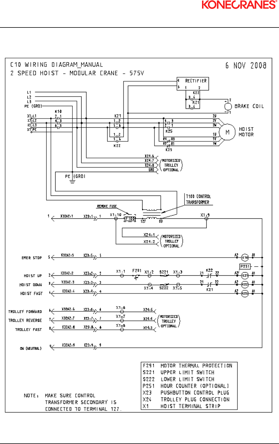
XN10 I&M MANUAL/EN/11.30.2010
56/85
This document and the information contained herein, is the exclusive property of Konecranes Plc and represents a non-public, confidential and proprietary trade secret that may not
be reproduced, disclosed to third parties, altered or otherwise employed in any manner whatsoever without the express written consent of Konecranes Plc. Copyright © (2010)
Konecranes Plc. All rights reserved.
7.25 Two-Speed Hoist – Modular Crane – 575 Volt Diagram
Figure 36. Two-speed hoist – modular crane – 575 volt diagram
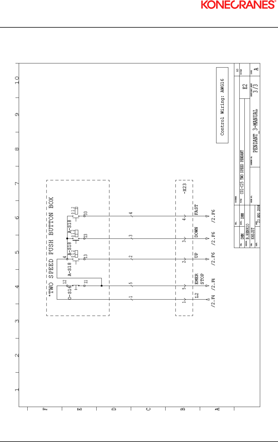
XN10 I&M MANUAL/EN/11.30.2010
57/85
This document and the information contained herein, is the exclusive property of Konecranes Plc and represents a non-public, confidential and proprietary trade secret that may not
be reproduced, disclosed to third parties, altered or otherwise employed in any manner whatsoever without the express written consent of Konecranes Plc. Copyright © (2010)
Konecranes Plc. All rights reserved.
7.26 Wiring Diagram – 3 Button – Push Button
Figure 37. Wiring diagram – 3 button – push button

XN10 I&M MANUAL/EN/11.30.2010
58/85
This document and the information contained herein, is the exclusive property of Konecranes Plc and represents a non-public, confidential and proprietary trade secret that may not
be reproduced, disclosed to third parties, altered or otherwise employed in any manner whatsoever without the express written consent of Konecranes Plc. Copyright © (2010)
Konecranes Plc. All rights reserved.
7.27 Wiring Diagram – 5 Button – Push Button
Figure 38. Wiring diagram – 5 button – push button

XN10 I&M MANUAL/EN/11.30.2010
59/85
This document and the information contained herein, is the exclusive property of Konecranes Plc and represents a non-public, confidential and proprietary trade secret that may not
be reproduced, disclosed to third parties, altered or otherwise employed in any manner whatsoever without the express written consent of Konecranes Plc. Copyright © (2010)
Konecranes Plc. All rights reserved.
7.28 Wiring Diagram – 7 Button – Push Button
Figure 39. Wiring diagram – 7 button – push button

XN10 I&M MANUAL/EN/11.30.2010
60/85
This document and the information contained herein, is the exclusive property of Konecranes Plc and represents a non-public, confidential and proprietary trade secret that may not
be reproduced, disclosed to third parties, altered or otherwise employed in any manner whatsoever without the express written consent of Konecranes Plc. Copyright © (2010)
Konecranes Plc. All rights reserved.
8 PREVENTATIVE MAINTENANCE
8.1 Maintenance and Inspection Table
Table 5. Maintenance Schedule
INSPECTION CHECK INTERVAL QUALIFIED PERSON
BRAKE OPERATION FOR HOLDING AND RELEASING DAILY OPERATOR
LOAD CHAIN FOR DAMAGE DAILY OPERATOR
SUSPENSION SUPPORT OF P/ B ASSEMBLY DAILY OPERATOR
CLEANLINESS & LUBRICATION OF LOAD CHAIN MONTHLY OPERATOR
UPPER / LOWER LIMIT SWITCHES DAILY OPERATOR
CHECK LOAD CHAIN FOR WEAR – MEASURE AND RECORD EVERY 3 MONTHS QUALIFIED INSPECTOR
CHECK HOOKS FOR WEAR MEASURE AND RECORD EVERY 3 MONTHS QUALIFIED INSPECTOR
CHECK LOAD BLOCK HARDWARE TO VERIFY TIGHTNESS EVERY 3 MONTHS OPERATOR
CHECK TOP HOOK / COUPLING HARDWARE FOR TIGHTNESS EVERY 3 MONTHS OPERATOR
CHECK SLIP CLUTCH & HOIST BRAKE ADJUSTMENT EVERY 3 -6 MONTHS QUALIFIED MECHANIC
CHECK LUBRICATION OF OPEN WHEEL GEARING EVERY 3 -6 MONTHS QUALIFIED MECHANIC
CHECK WIRE TERMINALS TIGHTNESS SEMI-ANNUALLY QUALIFIED MECHANIC
LUBRICATE 2-FALL LOAD BLOCK SPROCKET ANNUALLY OPERATOR
CHECK ALL HARDWARE FOR TIGHTNESS AND CORROSION ANNUALLY QUALIFIED MECHANIC
CLEAN MOTOR COOLING FINS ANNUALLY QUALIFIED MECHANIC
LUBRICATE ALL GEARING ANNUALLY QUALIFIED MECHANIC
INSPECT LOAD BLOCK THRUST BEARING ANNUALLY QUALIFIED MECHANIC
m
CAUTION: INSPECTION AND MAINTENANCE INTERVALS SHOULD BE ADJUSTED BASED
UPON OWNER / USER KNOWLEDGE OF APPLICATION, ENVIRONMENT, AND FREQUENCY
OF USE TO PREVENT DAMAGE TO PEOPLE, EQUIPMENT, AND FACILITIES.

XN10 I&M MANUAL/EN/11.30.2010
61/85
This document and the information contained herein, is the exclusive property of Konecranes Plc and represents a non-public, confidential and proprietary trade secret that may not
be reproduced, disclosed to third parties, altered or otherwise employed in any manner whatsoever without the express written consent of Konecranes Plc. Copyright © (2010)
Konecranes Plc. All rights reserved.
8.2 Lubrication
Table 6. Lubrication Specifications
LUBRICATION
POINT SPECIFICATIONS ACCEPTABLE LUBRICANTS QUANTITY
Chain Oil or Liquid grease Chain lubricating fluid (Ceplattyn
or similar) EP-90
As required
Idler sprocket
Slide bearing +
bearing
Grease (without MoS2)
KP 2 (DIN 51 502)
Soap-based lithium
Approx. drip point + 500°F
Worked penetration 509-563°F
Operating temperature - 4°F - +266°F
BP: BP Energrease LS - EP 2
Esso: Unirex N2
Mobil: Mobilgrease HP
Shell: Shell Alvanio EP Grease 2
As required
Gears KP 0 K grease (DIN 51502)
Soap-based lithium + MoS 2
Approx. drip point + 180°C
Worked penetration 355 - 385°C
Operating temperature -30°C to + 130°C
Mobil: Mobilgrease special
BP: Multi-purpose grease L 21 M
Shell: Shell Retimax AM
Texaco: Molytex grease EP 2
0.05 liter
Open Wheel Gearing: EP1 Mobilux or equivalent.

XN10 I&M MANUAL/EN/11.30.2010
62/85
This document and the information contained herein, is the exclusive property of Konecranes Plc and represents a non-public, confidential and proprietary trade secret that may not
be reproduced, disclosed to third parties, altered or otherwise employed in any manner whatsoever without the express written consent of Konecranes Plc. Copyright © (2010)
Konecranes Plc. All rights reserved.
8.3 Recommended technical support for various spare parts
Table 7. Recommended Technical Support for Various Spare Parts
SPARE PART REPLACED BY
Upper chain guide
Output shaft
PG cable gland
Gear shaft + nuts
Motor end cap
Gearing (1st/2nd stage)
Brake & end cap sealing
Other seals and O-rings
Brake-limiter
Brake end cap
Lower chain guide
Rubber buffer
Electric box
PC-board
Plugs
Chain
Chain bucket
Slack fall stop
Suspension hook
Hook block assembly
Control box
Qualified Electrician & Mechanic
Qualified Electrician & Mechanic
Qualified Electrician
Qualified Mechanic
Qualified Mechanic
Qualified Electrician & Mechanic
Qualified Mechanic
Qualified Mechanic
Qualified Electrician
Qualified Mechanic
Qualified Mechanic
Qualified Mechanic
Qualified Electrician
Qualified Electrician
Qualified Electrician
Qualified Mechanic
Qualified Mechanic
Qualified Mechanic
Qualified Mechanic
Qualified Mechanic
Qualified Electrician
NOTE: Once a part has been replaced, perform an operational check of hoist per
Sections 3.3 and 3.4.
8.4 Screw Tightening Torque (lb-ft) Specifications
Table 8. Screw Tightening Torque Specifications
TYPE M5 M6 M8 M10 M12
STANDARD SCREWS 4 7 18 35 61
SELF-TAPPING SCREWS 4 6 15 30 53

XN10 I&M MANUAL/EN/11.30.2010
63/85
This document and the information contained herein, is the exclusive property of Konecranes Plc and represents a non-public, confidential and proprietary trade secret that may not
be reproduced, disclosed to third parties, altered or otherwise employed in any manner whatsoever without the express written consent of Konecranes Plc. Copyright © (2010)
Konecranes Plc. All rights reserved.
8.5 Troubleshooting
Table 9. Troubleshooting
PROBLEM POSSIBLE CAUSE POSSIBLE SOLUTION
Hoist does not lift or lower load Emergency stop button is
activated Deactivate button
Blown fuse Replace the fuse
Motor thermal protection
activated Allow motor to cool down
Pendant plug pin pushed out Reinstall plug pin
Contactor terminal screws loose Tighten screws
Mainline switch shut off Turn switch on
Hoist does not lift load Overload condition Reduce load
Slip clutch worn or incorrectly
adjusted
Replace wear items or readjust
slip clutch torque
Brake not releasing
Check brake coil resistance.
Check air gap setting. Adjust if
necessary.
Check rectifier output voltage.
Load drifts more than 4 inches
[100mm]
Brake lining worn
Air gap on brake is too wide
Replace wear items as
necessary
Adjust air gap setting
Travel direction does not
correspond to that indicated on
push button
Power supply incorrectly
connected See SECTION 3
Abnormal noises while lifting or
lowering
Load chain and its components
are not lubricated Clean and lubricate load chain.
Load chain is worn Replace chain
Chain wheel or chain guide is
worn
Replace chain wheel or chain
guide
Idler sprocket is worn Replace idler sprocket
A supply phase is missing Connect the three phases
Twist or kink in load chain Remove twist or kink

XN10 I&M MANUAL/EN/11.30.2010
64/85
This document and the information contained herein, is the exclusive property of Konecranes Plc and represents a non-public, confidential and proprietary trade secret that may not
be reproduced, disclosed to third parties, altered or otherwise employed in any manner whatsoever without the express written consent of Konecranes Plc. Copyright © (2010)
Konecranes Plc. All rights reserved.
9 PARTS ILLUSTRATION
9.1 Hoist Body
Figure 40. Hoist body

XN10 I&M MANUAL/EN/11.30.2010
65/85
This document and the information contained herein, is the exclusive property of Konecranes Plc and represents a non-public, confidential and proprietary trade secret that may not
be reproduced, disclosed to third parties, altered or otherwise employed in any manner whatsoever without the express written consent of Konecranes Plc. Copyright © (2010)
Konecranes Plc. All rights reserved.
Table 10. Hoist Body Parts List
ITEM PART
NUMBER DESCRIPTION QTY
1 STATOR 1
2 2249955 SUSPENSION HOOK ASSEMBLY - PERPENDICULAR MOUNTING 1
2a 2242017 SAFETY LATCH – STEEL PLATE TYPE 1
2b 2242011 SUSPENSION MEMBER 1
2c 2249921 SUSPENSION BRACKET ASSEMBLY WITH AXLE AND SCREWS –
PERPENDICULAR MOUNTING (NOT SHOWN) 1
3 2249954 SUSPENSION HOOK ASSEMBLY – PARALLEL MOUNTING 1
3a 2242017 SAFETY LATCH – STEEL PLATE TYPE 1
3b 2249920 SUSPENSION BRACKET ASSEMBLY WITH AXLE AND SCREWS –
PARALLEL MOUNTING 1
52312841 SUSPENSION BRACKET ASSEMBLY WITH AXLE AND SCREWS –
PERPENDICULAR MOUNTING (FOR KPT TROLLEY) 1
4 2249904 MOTOR END CAP ASSEMBLY 1
5 2249903 BRAKE END CAP ASSEMBLY 1
6 2240011 BRAKE CAP ASSEMBLY 1
7 2218000 PUSHBUTTON CABLE FASTENING BRACKET 1
8 52340376 STICKERS AND COVERS XN 10 1
9 2218004 CABLE GUIDE 1
10 2240013 SEALING RING AND O-RING FOR BRAKE CAP 1
11 - MOTOR DATA PLATE 1
12 2213309008 CAPACITY STICKER – 500 kg 1
12 2213309009 CAPACITY STICKER – 1000 kg 1
12 2213309016 CAPACITY STICKER – 1500 kg 1
12 2213309010 CAPACITY STICKER – 2000 kg 1
12 2213309002 CAPACITY STICKER – ½ ton 1
12 2213309003 CAPACITY STICKER – 1 ton 1
12 2213309014 CAPACITY STICKER – 1.5 ton 1
12 2213309004 CAPACITY STICKER – 2 ton 1

XN10 I&M MANUAL/EN/11.30.2010
66/85
This document and the information contained herein, is the exclusive property of Konecranes Plc and represents a non-public, confidential and proprietary trade secret that may not
be reproduced, disclosed to third parties, altered or otherwise employed in any manner whatsoever without the express written consent of Konecranes Plc. Copyright © (2010)
Konecranes Plc. All rights reserved.
9.2 Gear Mechanism With Motor Brake
Figure 41. Gear mechanism with motor brake
ITEM QTY
PART NO. DESCRIPTION
1 1 2249940 Slipping clutch spring with motor shaft
2 1 2245025 Rotor assembly - 1 and 2-speed type
3 1 2249941 Chain sprocket assembly
4 1 2249937 Planetary gear train - 1st step -
5 1 2249938 Planetary gear train - 2nd step - 8M/MN (reducing 58)
5 1 2249951 Planetary gear train - 2nd step - 16M/mn (reducing 29)
6 1 2241074 Brake assembly complete with brake cap – 190 VDC / 380-480 VAC
6 1 2241073 Brake assembly complete with brake cap – 100 VDC / 208-230 VAC
6 1 2241072 Brake assembly complete with brake cap – 230 VDC / 575 VAC
7 1 2249972 Slipping clutch friction assembly
8 1 2248001 Brake, complete 190 VDC / 380-480 VAC
8 1 2248000 Brake, complete 100 VDC / 208-230 VAC
8 1 2248003 Brake, complete 230VDC / 575 VAC
9 1 2240012 Set of seals for brake cap
10 1 2241501 Motor shaft

XN10 I&M MANUAL/EN/11.30.2010
67/85
This document and the information contained herein, is the exclusive property of Konecranes Plc and represents a non-public, confidential and proprietary trade secret that may not
be reproduced, disclosed to third parties, altered or otherwise employed in any manner whatsoever without the express written consent of Konecranes Plc. Copyright © (2010)
Konecranes Plc. All rights reserved.
THIS PAGE INTENTIONALLY LEFT BLANK

XN10 I&M MANUAL/EN/11.30.2010
68/85
This document and the information contained herein, is the exclusive property of Konecranes Plc and represents a non-public, confidential and proprietary trade secret that may not
be reproduced, disclosed to third parties, altered or otherwise employed in any manner whatsoever without the express written consent of Konecranes Plc. Copyright © (2010)
Konecranes Plc. All rights reserved.
9.3 Lifting Assembly
Figure 42. Lifting assembly

XN10 I&M MANUAL/EN/11.30.2010
69/85
This document and the information contained herein, is the exclusive property of Konecranes Plc and represents a non-public, confidential and proprietary trade secret that may not
be reproduced, disclosed to third parties, altered or otherwise employed in any manner whatsoever without the express written consent of Konecranes Plc. Copyright © (2010)
Konecranes Plc. All rights reserved.
Table 11. Lifting Assembly Parts List
ITEM
PART NUMBER
DESCRIPTION QTY
1 2249983 1-FALL LIFTING HOOK BLOCK – STANDARD TYPE 1
1 2242018 1-FALL LIFTING HOOK BLOCK – SELF-LOCKING TYPE 1
1a 001515 SAFETY LATCH – STEEL WIRE TYPE - 1 FALL 1
1a 2212017 SAFETY LATCH – STEEL PLATE TYPE - 1 FALL 1
1b 2217004 1-FALL LIFTING HOOK – STANDARD TYPE 1
1b 2247015 1-FALL LIFTING HOOK – SELF-LOCKING TYPE 1
1c 2249976 SET OF 2 HALF-CASINGS WITH AXLE AND SCREWS 1
1d 2213333002 CAPACITY STICKER – ½ TON – 1 FALL 1
1d 2213333004 CAPACITY STICKER – 1 TON – 1 FALL 1
1d 2213333009 CAPACITY STICKER – 500 kg – 1 FALL 1
1d 2213333011 CAPACITY STICKER – 1000 kg – 1 FALL 1
2 2249984 2-FALL LIFTING HOOK BLOCK – STANDARD TYPE 1
2 2242028 2-FALL LIFTING HOOK BLOCK – SELF-LOCKING TYPE 1
2a 001513 SAFETY LATCH – STEEL WIRE TYPE – 2 FALLS 1
2a 2242017 SAFETY LATCH – STEEL PLATE TYPE – 2 FALLS 1
2b 2242021 2-FALL LIFTING HOOK – STANDARD TYPE 1
2b 2267015 2-FALL LIFTING HOOK – SELF-LOCKING TYPE 1
2c 2249978 SET OF 2 HALF-CASINGS WITH AXLE, RETURN SPROCKET AND
SCREWS 1
2d 2213333004 CAPACITY STICKER – 1 TON – 2 FALLS 1
2d 2213333005 CAPACITY STICKER – 2 TON – 2 FALLS 1
2d 2213333011 CAPACITY STICKER – 1000 kg – 2 FALLS 1
2d 2213333012 CAPACITY STICKER – 2000 kg – 2 FALLS 1
3 2243523 CHAIN ANCHOR ASSEMBLY 1
4 52293746 UPPER AND LOWER CHAIN GUIDE ASSEMBLY WITH RUBBER
BUFFER 1
4a 2244008 RUBBER BUFFER 1
2244011 UPPER CHAIN GUIDE 1
5a 2249925 CHAIN BUCKET – 25FT [8M] MAXIMUM CHAIN LENGTH 1
5b 2249926 CHAIN BUCKET – 50FT [16M] MAXIMUM CHAIN LENGTH 1
5c 2249932 CHAIN BUCKET – 75FT [30M] MAXIMUM CHAIN LENGTH 1
5d 2249933 CHAIN BUCKET – 150FT [50M] MAXIMUM CHAIN LENGTH 1
6 2249942 SLACK FALL STOP ASSEMBLY 1
7a 2243500 LOAD CHAIN – GALVANIZED TYPE *
7b 2243501 LOAD CHAIN – BLACK TYPE *
7c 2243502 LOAD CHAIN – STAINLESS STEEL TYPE *
8 2241045 LOAD CHAIN INSERTION TOOL 1
9 9995008 CHAIN LUBRICANT 1
* NOTE: REFER TO CHAIN HOIST LIFT AND NUMBER OF FALLS FOR CHAIN QUANTITY
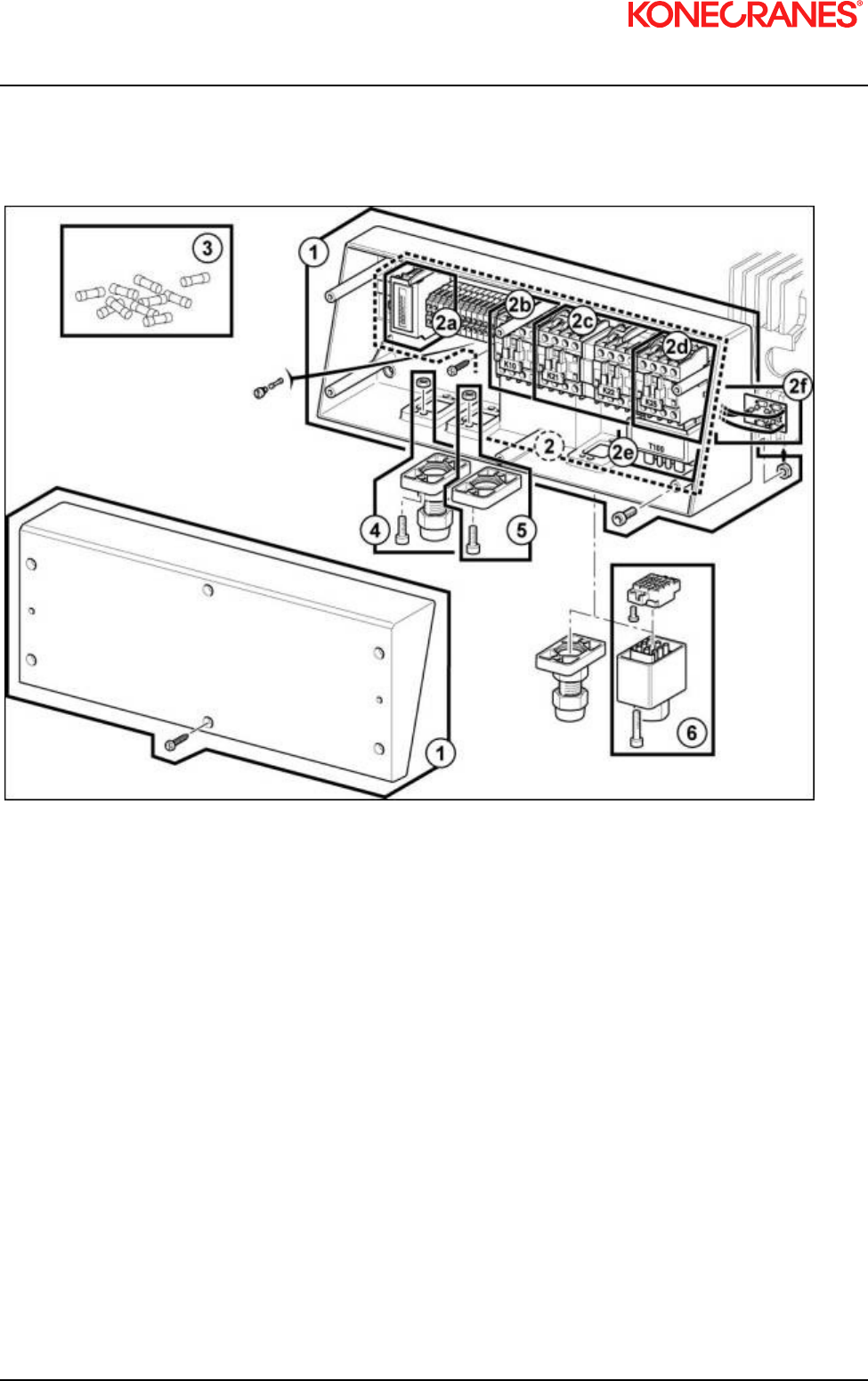
XN10 I&M MANUAL/EN/11.30.2010
70/85
This document and the information contained herein, is the exclusive property of Konecranes Plc and represents a non-public, confidential and proprietary trade secret that may not
be reproduced, disclosed to third parties, altered or otherwise employed in any manner whatsoever without the express written consent of Konecranes Plc. Copyright © (2010)
Konecranes Plc. All rights reserved.
9.4 Controls

XN10 I&M MANUAL/EN/11.30.2010
71/85
This document and the information contained herein, is the exclusive property of Konecranes Plc and represents a non-public, confidential and proprietary trade secret that may not
be reproduced, disclosed to third parties, altered or otherwise employed in any manner whatsoever without the express written consent of Konecranes Plc. Copyright © (2010)
Konecranes Plc. All rights reserved.
Table 12. Controls Parts List
ITEM PART
NUMBER DESCRIPTION QTY
1 2249965 ELECTRIC CUBICLE (LID, COVER AND SCREWS) 1
2 2243016 PRINTED CIRCUIT BOARD – 2 SPEED HOISTING + ON-OFF – 575V
60 Hz 115V AC 1
2 2243017 PRINTED CIRCUIT BOARD – 2 SPEED HOISTING + ON-OFF – 460V
60 Hz 115V AC 1
2 2243018 PRINTED CIRCUIT BOARD – 2 SPEED HOISTING + ON-OFF – 230V
60 Hz 115V AC 1
2 52339762 PRINTED CIRCUIT BOARD – SINGLE SPEED HOISTING + ON-OFF –
208/230V/460V 60 Hz 115V AC RECONNECTABLE 1
2a 2213028 HOUR COUNTER 115V AC 60 Hz 1
2b 7983055 EMERGENCY STOP CONTACTOR K10 115V AC 1
2c 7983056 REVERSING CONTACTOR K21 or K22 115V AC (coef. 2) 1
2d 7983057 SELECTING CONTACTOR K25 115V AC 1
2e 7983029 TRANSFORMER 400V 50&60Hz 115V AC 1
2e 7983027 TRANSFORMER 575V 60Hz 115V AC 1
2e 7983026 TRANSFORMER 230V/460V 60Hz 115V AC 1
2f 2243060 RECTIFIER 230V/400V/460V500V/575V 1
2f 2243061 RECTIFIER 230V/460V - RECONNECTABLE 1
3 52330744 SET OF10 FUSES (115V) 1
4 2249947 CABLE GLAND ASSEMBLY 1
5 2219814 CLOSING PLATE ASSEMBLY 1
6 2249945 CONNECTING PLUG SET FOR PUSHBUTTON BOX 1
6 2249946 CONNECTING PLUG SET FOR PUSHBUTTON FOR TROLLEY 1
6 2249982 CONNECTING PLUG SET FOR POWER SUPPLY 1
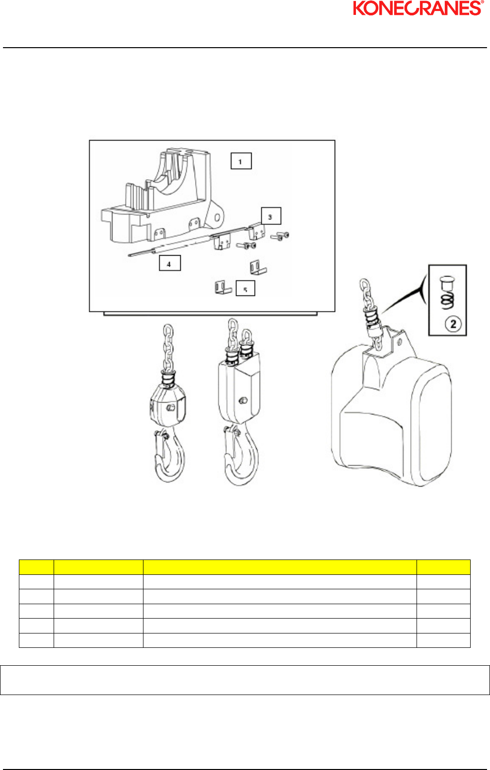
XN10 I&M MANUAL/EN/11.30.2010
72/85
This document and the information contained herein, is the exclusive property of Konecranes Plc and represents a non-public, confidential and proprietary trade secret that may not
be reproduced, disclosed to third parties, altered or otherwise employed in any manner whatsoever without the express written consent of Konecranes Plc. Copyright © (2010)
Konecranes Plc. All rights reserved.
9.5 Upper and Lower Limit Switch
Figure 43. Upper and lower limit switch
Table 13. Chain Guide Assembly with Limit Switches Parts List
ITEM PART NUMBER DESCRIPTION QTY
1 2243050 MICRO-SWITCHES ASSEMBLY 1
2 52295974 SPRING ASSEMBLY AND SUPPORT 1
3 7291040 MICRO SWITCHES 1
4 - CABLE GUIDE 1
5 52337705 SLIDES 2
m
CAUTION: Cut off the main power supply before doing any work on the electrical cubicle.
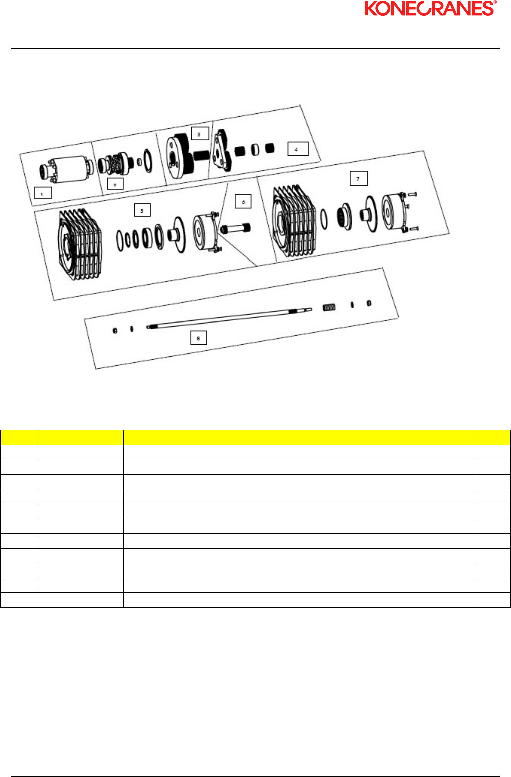
XN10 I&M MANUAL/EN/11.30.2010
73/85
This document and the information contained herein, is the exclusive property of Konecranes Plc and represents a non-public, confidential and proprietary trade secret that may not
be reproduced, disclosed to third parties, altered or otherwise employed in any manner whatsoever without the express written consent of Konecranes Plc. Copyright © (2010)
Konecranes Plc. All rights reserved.
9.6 Double Brake Mechanism
Table 14. Double Brake Mechanism Parts List
ITEM PART NUMBER DESCRIPTION QTY
1 2245025 ROTOR ASSEMBLY 1
2 2249941 CHAIN SPROCKET ASSEMBLY 1
3 2249938 PLANETARY GEAR TRAIN - 2
nd
STEP - 8M/MN (REDUCING 58) 1
3 2249951 PLANETARY GEAR TRAIN - 2
nd
STEP - 16M/mn (REDUCING 29) 1
4 2249937 PLANETARY GEAR TRAIN – 1
ST
STEP 1
5 2249006 BRAKE ASSEMBLY COMPLETE WITH BRAKE CAP – 1
ST
BRAKE – 190 VDC / 380-480 VAC 1
5 2249016 BRAKE ASSEMBLY COMPLETE WITH BRAKE CAP – 1
ST
BRAKE – 100 VDC / 208-230 VAC 1
6 2249054 PINION 1
7 2249007 BRAKE ASSEMBLY COMPLETE WITH BRAKE CAP – 2
nd
BRAKES – 190 VDC / 380-480 VAC 1
7 2249017 BRAKE ASSEMBLY COMPLETE WITH BRAKE CAP – 2
nd
BRAKES – 100 VDC / 208-230 VAC 1
8 2249051 DOUBLE BRAKE MOTOR SHAFT 1
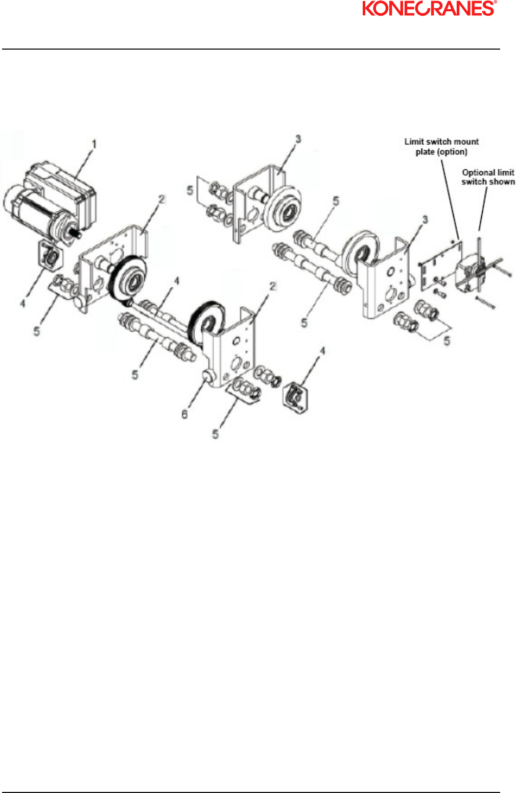
XN10 I&M MANUAL/EN/11.30.2010
74/85
This document and the information contained herein, is the exclusive property of Konecranes Plc and represents a non-public, confidential and proprietary trade secret that may not
be reproduced, disclosed to third parties, altered or otherwise employed in any manner whatsoever without the express written consent of Konecranes Plc. Copyright © (2010)
Konecranes Plc. All rights reserved.
9.7 Low Headroom Trolley
9.7.1 Low Headroom Trolley (Drive Components)

XN10 I&M MANUAL/EN/11.30.2010
75/85
This document and the information contained herein, is the exclusive property of Konecranes Plc and represents a non-public, confidential and proprietary trade secret that may not
be reproduced, disclosed to third parties, altered or otherwise employed in any manner whatsoever without the express written consent of Konecranes Plc. Copyright © (2010)
Konecranes Plc. All rights reserved.
Table 15. Low Headroom Trolley Short Outreach (Drive Components)
ITEM DESCRIPTION C10 SHORT
QTY CODE
1
Complete 2-speed motor drive 115Vc
460V
≤ 2 Ton
(2000 Kg)
1 52306026
575V 1 52306027
208/230V 1 52306028
Complete inverter motor drive 115Vc
460V
575V
208/230V
> 1 Ton
(1000 Kg) 1 52299090
> 1 Ton
≤ 2 Ton 1 52304881
2 Geared drive side plates 2 52391073
3 Ungeared idler side plates 2 52391072
4 Pinion drive assy 1 52311194
5
XHEAD assy 2.28 - 4.33 in. (set of 4) 4 556902
XHEAD assy 4.45 - 6.69 in. (set of 4) 4 556903
XHEAD assy 7.00 – 9.45 in. (set of 4) 4 556904
XHEAD assy 9.76 – 12.20 in. (set of 4) 4 556905
6 Rubber buffer 4 558993
* Transformer for inverter trolley
460V 1 52304748
575V 1 52304749
208/230V 1 52304746
* Transformer mounting bracket 1 2309848001
* Not shown in diagram
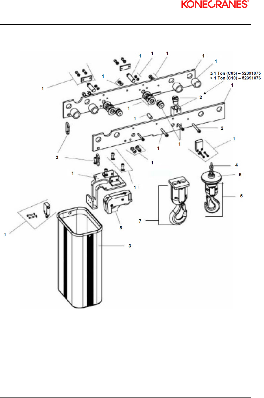
XN10 I&M MANUAL/EN/11.30.2010
76/85
This document and the information contained herein, is the exclusive property of Konecranes Plc and represents a non-public, confidential and proprietary trade secret that may not
be reproduced, disclosed to third parties, altered or otherwise employed in any manner whatsoever without the express written consent of Konecranes Plc. Copyright © (2010)
Konecranes Plc. All rights reserved.
9.7.2 Low Headroom Trolley (Suspension Components)
Figure 44. Low headroom trolley (suspension components)

XN10 I&M MANUAL/EN/11.30.2010
77/85
This document and the information contained herein, is the exclusive property of Konecranes Plc and represents a non-public, confidential and proprietary trade secret that may not
be reproduced, disclosed to third parties, altered or otherwise employed in any manner whatsoever without the express written consent of Konecranes Plc. Copyright © (2010)
Konecranes Plc. All rights reserved.
Table 16. Low Headroom Trolley (Suspension Components)
ITEM DESCRIPTION C10 SHORT
QTY CODE
1 LH Short Outreach Frame Assy 1 52391066
2 Fixed point assy (not applicable for 1-fall hoists) 1 52391076
3 Chain bag (from 0 to 30 m) to 65 ft. 1 52333407
66 to130 ft. 1 52328053
4 Lifting chain galva. (Length: HOL + 5 ft.) - 2243500
5 Lower hook block assy 1 fall 1 52387611
6 Counterweight for 1 fall hook 1 557939
7 Lower hook block assy 2 falls 1 52387610
8 Chain guide 1 52425117
NOTE: When hoists are mounted on a low headroom trolley, they are supplied with aluminum chain
guide.

XN10 I&M MANUAL/EN/11.30.2010
78/85
This document and the information contained herein, is the exclusive property of Konecranes Plc and represents a non-public, confidential and proprietary trade secret that may not
be reproduced, disclosed to third parties, altered or otherwise employed in any manner whatsoever without the express written consent of Konecranes Plc. Copyright © (2010)
Konecranes Plc. All rights reserved.
9.8 Electric trolley (Swiveling trolley 0 to 3.2 Tons (3200 Kg))
Figure 45. Electric trolley (swiveling trolley 0 to 3.2 tons (3200 Kg))
NOTE: ECH is attached to swivel trolley through a mechanical connection. No top hook connection
available.
5

XN10 I&M MANUAL/EN/11.30.2010
79/85
This document and the information contained herein, is the exclusive property of Konecranes Plc and represents a non-public, confidential and proprietary trade secret that may not
be reproduced, disclosed to third parties, altered or otherwise employed in any manner whatsoever without the express written consent of Konecranes Plc. Copyright © (2010)
Konecranes Plc. All rights reserved.
Table 17. Electric trolley (Swiveling trolley 0 to 3.2 Tons (3200 Kg))
ITEM
DESCRIPTION QTY CODE
1
Complete 2-speed motor drive
115Vc
460V
575V
208/230V
≤ 3.2 Ton
(3200 Kg)
2 52306026
2 52306027
2 52306028
Complete inverter motor drive
115Vc 460V
575V
208/230V
≤ 1 Ton
(1000 Kg) 2 52299090
> 1 Ton
≤ 3.2 Ton 2 52304881
2 Idler side plate 2 52326596
3 Drive side plate 2 52326597
4
Swivel CHRD Kit 2.60 – 4.33 in. (set of 4) 1 556966
Swivel CHRD Kit 2.60 – 4.33 in. (set of 4) 1 556967
Swivel CHRD Kit 2.60 – 4.33 in. (set of 4) 1 556968
Swivel CHRD Kit 2.60 – 4.33 in. (set of 4) 1 556969
5
Cross bar set for C05 1 52326598
Cross bar set for C10 1 52326599
Cross bar set for C16/20/25 1 52326602

XN10 I&M MANUAL/EN/11.30.2010
80/85
This document and the information contained herein, is the exclusive property of Konecranes Plc and represents a non-public, confidential and proprietary trade secret that may not
be reproduced, disclosed to third parties, altered or otherwise employed in any manner whatsoever without the express written consent of Konecranes Plc. Copyright © (2010)
Konecranes Plc. All rights reserved.
9.9 Push Button Assembly – Horizontal Pairs of Buttons
Figure 46. Push button assembly – horizontal pairs of buttons
Table 18. Push Button Assembly (Horizontal Pairs of Buttons) Parts List
ITEM PART NUMBER DESCRIPTION QTY
- 2309765010 P/B ASSEMBLY 10 FT, E-STOP, TWO SPEED HOIST 1
- 2309765015 P/B ASSEMBLY 15 FT, E-STOP, TWO SPEED HOIST 1
- 2309765020 P/B ASSEMBLY 20 FT, E-STOP, TWO SPEED HOIST 1
- 2309767010 P/B ASSEMBLY 10 FT, E-STOP, TWO SPEED HOIST, TWO SPEED TROLLEY 1
- 2309767015 P/B ASSEMBLY 15 FT, E-STOP, TWO SPEED HOIST, TWO SPEED TROLLEY 1
- 2309767020 P/B ASSEMBLY 20 FT, E-STOP, TWO SPEED HOIST, TWO SPEED TROLLEY 1
1a 52301832 P/B ENCLOSURE ASSEMBLY – E-STOP – TS HOIST 1
1b 2213466004 P/B ENCLOSURE ASSEMBLY – E-STOP – TS HOIST, TWO SPEED TROLLEY 1
2 2218000 UPPER SUSPENSION KIT 1
3 7285036 P/B ASSEMBLY - PLUG KIT 1
4 558073 SUSPENSION UNIT 1
5 52292266 PUSH BUTTON ELECTRICAL CABLE 16 GAUGE / 12 CONDUCTOR RPC 1
6 2309414004 XN OPERATOR’S WARNING TAG - ENGLISH 1

XN10 I&M MANUAL/EN/11.30.2010
81/85
This document and the information contained herein, is the exclusive property of Konecranes Plc and represents a non-public, confidential and proprietary trade secret that may not
be reproduced, disclosed to third parties, altered or otherwise employed in any manner whatsoever without the express written consent of Konecranes Plc. Copyright © (2010)
Konecranes Plc. All rights reserved.
9.10 Push Button Assembly – Horizontal Pairs of Buttons
Figure 47. Push button assembly – horizontal pairs of buttons
Table 19. Push Button Assembly – Horizontal Pairs of Buttons Parts List
ITEM PART NUMBER DESCRIPTION QTY
1 52301832 PISTOL GRIP P/B CONTROL ASSEMBLY – TWO SPEED 1
2 2213466004 P/B CONTROL ASSEMBLY – TWO SPEED – 5 BUTTON 1
3 2213466005 P/B CONTROL ASSEMBLY – TWO SPEED – 7 BUTTON 1
2
1
3

XN10 I&M MANUAL/EN/11.30.2010
82/85
This document and the information contained herein, is the exclusive property of Konecranes Plc and represents a non-public, confidential and proprietary trade secret that may not
be reproduced, disclosed to third parties, altered or otherwise employed in any manner whatsoever without the express written consent of Konecranes Plc. Copyright © (2010)
Konecranes Plc. All rights reserved.
9.11 Push Button Assembly – Vertical Pairs of Buttons (Option)
Figure 48. Push button assembly – vertical pairs of buttons

XN10 I&M MANUAL/EN/11.30.2010
83/85
This document and the information contained herein, is the exclusive property of Konecranes Plc and represents a non-public, confidential and proprietary trade secret that may not
be reproduced, disclosed to third parties, altered or otherwise employed in any manner whatsoever without the express written consent of Konecranes Plc. Copyright © (2010)
Konecranes Plc. All rights reserved.
Table 20. Push Button Assembly – Vertical Pairs of Buttons (Option) Parts List
ITEM PART
NUMBER DESCRIPTION QTY
- 2309673010 E-STOP, SINGLE SPEED HOIST – 10 FT P/B ASSEMBLY 1
- 2309673015 E-STOP, SINGLE SPEED HOIST – 15 FT P/B ASSEMBLY 1
- 2309673020 E-STOP, SINGLE SPEED HOIST – 20 FT P/B ASSEMBLY 1
- 2309674010 E-STOP, TWO SPEED HOIST – 10 FT P/B ASSEMBLY 1
- 2309674015 E-STOP, TWO SPEED HOIST – 15 FT P/B ASSEMBLY 1
- 2309674020 E-STOP, TWO SPEED HOIST – 20 FT P/B ASSEMBLY 1
1 2212932011 E-STOP, SS HOIST PUSHBUTTON ENCLOSURE ASSEMBLY 1
1 2212932012 E-STOP, TS HOIST PUSHBUTTON ENCLOSURE ASSEMBLY 1
2 2218000 UPPER SUSPENSION KIT 1
3 7285036 PLUG KIT 1
4 558073 SUSPENSION UNIT 1
5 52292266 PUSH BUTTON ELECTRICAL CONTROL CABLE 1
6 2309414004 XN PUSHBUTTON WARNING TAG - ENGLISH 1

XN10 I&M MANUAL/EN/11.30.2010
84/85
This document and the information contained herein, is the exclusive property of Konecranes Plc and represents a non-public, confidential and proprietary trade secret that may not
be reproduced, disclosed to third parties, altered or otherwise employed in any manner whatsoever without the express written consent of Konecranes Plc. Copyright © (2010)
Konecranes Plc. All rights reserved.
9.12 Push Button Assembly – Vertical Buttons (Option)
Figure 49. Push button assembly – vertical buttons
Table 21. Push Button Assembly - Vertical Buttons (Option) Parts List
ITEM PART
NUMBER DESCRIPTION QTY
1 2212932011 3 BUTTON P/B TELEMECANIQUE – S*, 1H 1
1 2212932012 3 BUTTON P/B TELEMECANIQUE – S*, 2H 1
2 2212932032 5 BUTTON P/B TELEMECANIQUE – S*, 1H, 2T 1
2 2212932033 5 BUTTON P/B TELEMECANIQUE – S*, 2H, 2T 1
3 2212932034 7 BUTTON P/B TELEMECANIQUE – S*, 2H, 2T, 2B 1
3 2212932035 7 BUTTON P/B TELEMECANIQUE – S*, 1H, 2T, 1B 1
3 2212932036 7 BUTTON P/B TELEMECANIQUE – S*, 2H, 2T, 1B 1
3 2212932037 7 BUTTON P/B TELEMECANIQUE – S*, 1H, 2T, 2B 1

XN10 I&M MANUAL/EN/11.30.2010
85/85
This document and the information contained herein, is the exclusive property of Konecranes Plc and represents a non-public, confidential and proprietary trade secret that may not
be reproduced, disclosed to third parties, altered or otherwise employed in any manner whatsoever without the express written consent of Konecranes Plc. Copyright © (2010)
Konecranes Plc. All rights reserved.
THIS PAGE INTENTIONALLY LEFT BLANK
