63 1157 M9481, M9484, M9491, M9494 Modutrol 4 Motors Honeywell Burner M948X M949X Sd EN
User Manual: Honeywell Burner M9494
Open the PDF directly: View PDF ![]() .
.
Page Count: 4
® U.S. Registered Trademark
Copyright © 1996 Honeywell Inc. • All Rights Reserved
SPECIFICATION DATA
63-1157-2
M9481, M9484, M9491, M9494
Modutrol IV
™
Motors
FEATURES
• Replace M941 Motors.
• Oil immersed motor and gear train provide reliable
performance and long life.
• Wiring box provides NEMA 3 weather protection.
• Quick-connect terminals standard—screw terminal
adapter available.
• Adapter bracket for matching shaft height of older
motors is standard with replacement motors.
• Die-cast aluminum housing
• Field addable interface modules can be mounted in
wiring box to upgrade actuator to Series 70
(electronic) Control.
• Models available with tapped output shaft.
APPLICATION
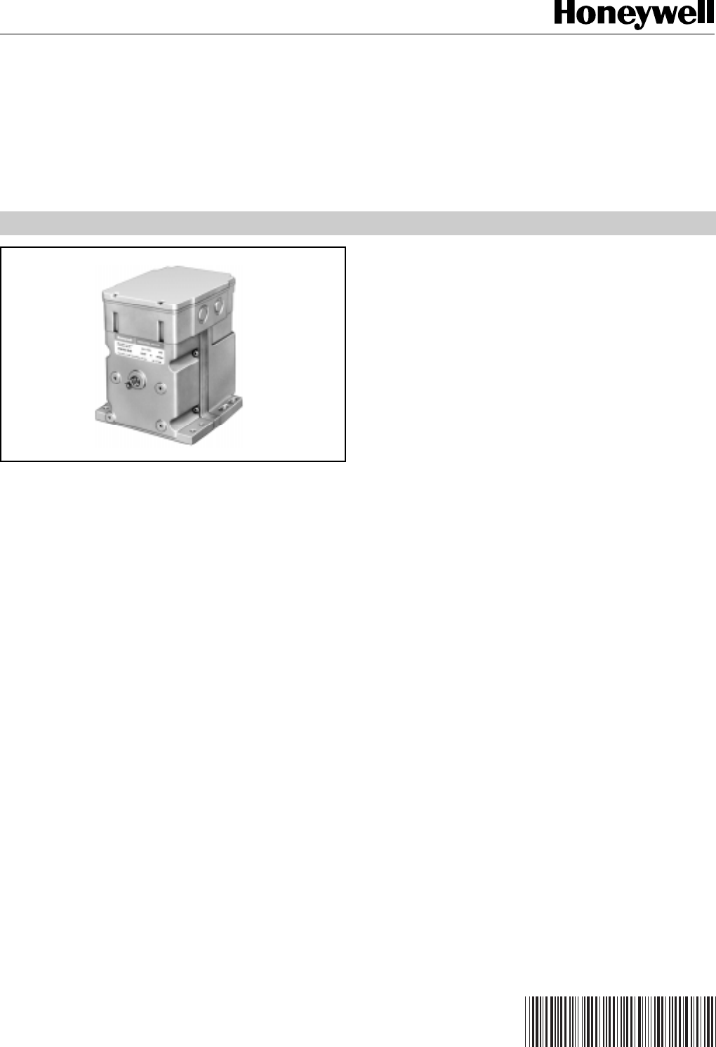
M9481, M9484, M9491 and M9494 Modutrol® Motors are low
voltage, reversing proportional control actuators for valves,
dampers and auxiliary equipment. They are especially
designed for commercial or industrial oil or gas burner control
systems.
❑M9481
❑M9484
❑M9491
❑M9494
2
M9481, M9484, M9491, M9494 Modutrol IV™ MOTORS
63-1157—2
SPECIFICATIONS
M9481D,E,F
M9484D,E,F
M9491D
M9494D
N
Maximum Damper Rating:
Dead Weight Load On Shaft:
Power or Auxiliary End: 200 lb (90.8 kg) maximum.
Maximum Combined Load: 300 lb (136 kg).
Ambient Temperature Ratings:
Maximum: 150°F (66°C) at 25% duty cycle.
Minimum: Minus 40°F (-40°C).
Crankshaft: 3/8 in. (9.5 mm) Square.
M9484, M9494 have dual-ended shaft.
M9481, M9491 have single-ended shaft.
Auxiliary Switch Ratings (Amperes):
M94XXE has 1 spdt switch.
M94XXF has 2 spdt switches.
Dimensions:
See Fig. 1.
Underwriters Laboratories Inc. Listed:
File No. E4436, Guide No. XAPX.
Canadian Standards Association Certified:
General Listing File No. LR1620, Guide No. 400-E.
Timing And Torque:
NOTE: Motors with 2 min. timing at 90° stroke or 4 min.
timing at 160° stroke contain on-off pulsing circuitry
to achieve timing. Intermittent operation is normal.
Timing Torque in lb-in (N•m)
90° Stroke
Motors 160° Stroke
Motors Normal
Running Breakaway
Torquea
15 sec 30 sec 75 (8.5) 150 (17.0)
30 sec 1 min 150 (17.0) 300 (34.0)
1, 2 minb2, 4 minb300 (34.0) 600 (68.0)
aBreakaway torque is the maximum torque available to
overcome occasional large loads such as a seized
damper or valve.
Motor must not be used continuously at
this rating.
bStalling of 4 minute motor may damage drive shaft.
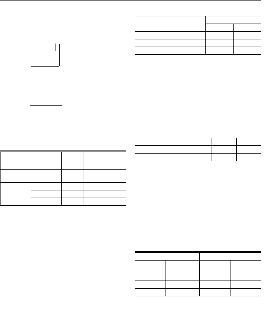
Control Type
94 is Series 90
Power Rating
8is high torque: 150 lb-in.
at standard timing
(60 sec for 160°)
9is high torque: 300 lb-in.
at 2 or 4 min timing
Suffix Letter
D: Adjustable stroke
(90° to 160°),
No auxiliary switches
E: Adjustable stroke
(90° to 160°),
1 auxiliary switch
F: Adjustable stroke
(90° to 160°),
2 auxiliary switches
Output Drive
4 is dual-ended shaft, non-spring return
1 is single-ended shaft, non-spring return
NOTE: Some motors furnished to equipment manufacturers
have no adapter bracket, a single-ended shaft and/
or no wiring box.
Electrical Ratings:
Controller Type:
Series 90 Control Circuit: 135 ohm, Series 90 proportioning
controller. Series 90 high or low limit controller with manual
minimum position potentiometer (with a combined total
resistance of up to 500 ohms) can also be used in the control
circuit.
Motor Rotation:
Normally closed. (The normal position is the position the
motor assumes with controller disconnected.) The closed
position is the limit of counterclockwise rotation as viewed
from the power end of the motor. Motor opens clockwise (as
viewed from the power end). Motors are shipped in the closed
position.
Stroke:
Field adjustable from 90° to 160°. Start position of shaft
changes with adjustment of stroke. (Midpoint of stroke
remains fixed as stroke is adjusted.) Stroke is adjusted using
cams located in wiring compartment. Motors are shipped with
stroke set at 90°.
Voltage
(V at 50/
60 Hz) Current
Draw (A) Power
Consumption (W)
Without
Transformera24 0.8 18
With Internal 120 0.24 23
Transformer 208 0.14 23
240 0.12 23
aInternal transformer can be field added.
N NN
One Contacta120V 240V
Full Load 7.2 3.6
Locked Rotor 43.2 21.6
a40 VA pilot duty, 120/240 Vac on opposite contact.
B dim
Motor Torque lb-in. in. mm
75 100 2540
150 202 5131
300 258 6553

M9481, M9484, M9491, M9494 Modutrol IV™ MOTORS
3 63-1157—2
Accessories:
ES650117 Explosion-proof Housing: Encloses motor for
use in explosive atmospheres. Not for use with Q601,
Q618, and Q455 Linkages. Order from Nelson Electric
Co. Requires Honeywell 7617DM Coupling.
Q607 External Auxiliary Switch: Controls auxiliary
equipment as a function of motor position.
Q605 Damper Linkage: Connects motor to damper.
Includes motor crank arm.
Q618 Linkage: Connects Modutrol motor to water or steam
valve.
Q601 Bracket and Linkage Assembly: Connects Modutrol
motor to water or steam valve.
Q100A,B Linkage: Connects Modutrol motor to butterfly
valve. Requires adapter bracket packed with motor.
Q209E,F Potentiometer: Limits minimum position of motor.
Q68 Dual Control Potentiometer: Controls 1 to 9 additional
motors.
Q181 Auxiliary Potentiometer: Controls 1 or 2 additional
motors.
221455A Infinitely Adjustable Crank Arm: Approximately
0.75 in. (19 mm) shorter than the 4074ELY Crank Arm.
Can rotate through downward position and clear base
of motor without requiring use of adapter bracket.
7617ADW Adjustable Crank Arm: Approximately 0.75 in.
(19 mm) shorter than the 7616BR Crank Arm. Can
rotate through the downward position and clear base of
motor without requiring use of adapter bracket.
220741A
Screw Terminal Adapter: Converts the standard
quick-connect terminals to screw terminals.
Transformers: Mounted internally, provide 24 Vac power to
motor.
198162JA—24 Vac; 50/60 Hz (for electrical isolation).
198162EA—120 Vac; 50/60 Hz.
198162GA—220 Vac; 50/60 Hz.
198162AA—120/208/240 Vac; 50/60 Hz.
Q7130A: Interface Module with selectable voltage ranges
(4-7 Vdc, 6-9 Vdc, and 10.5-13.5 Vdc). Adapts motor to
M71XX function.
Q7230A: Interface Module, selectable voltage or current
control, with adjustable null and span. Adapts motor to
M72XX function; 4 to 20 mA or 2 to 10 Vdc.
Q7330A: Interface Module, for W936 Economizer
applications. Adapts motor to M73XX function.
Q7630A: Interface Module, 3-wire 14-17 Vdc control with
minimum position capability. Adapts motor to M76XX
function.
4074BYK: Controls up to 6 M91XX motors in unison from
one Series 90 Controller.
4074EAU: Drives 2 or 3 M91XX motors from a W973
Single-zone Logic Panel or W7100 Discharge Air
Controller.
4074EDC: Drives one M91XX motor from a 4-20 mA
controller.
4074EED: Drives up to 4 M91XX motors from a 4-20 mA
controller.
221508A Resistor Board—plugs onto quick-connect
terminals in wiring box of M91XX motor. Can be used in
place of 4074BYK, EAU, EDC, or EED resistor kits
(functions described above).
4
M9481, M9484, M9491, M9494 Modutrol IV™ MOTORS
63-1157—2
Honeywell Europe S.A.
3 Avenue du Bourget
B-1140 Brussels Belgium
Honeywell Asia Pacific Inc.
Room 3213-3225
Sun Hung Kai Centre
No. 30 Harbour Road
Wanchai
Hong Kong
Home and Building Control
Honeywell Limited-Honeywell Limitée
155 Gordon Baker Road
North York, Ontario
M2H 2C9
Honeywell Latin American Division
Miami Lakes Headquarters
14505 Commerce Way Suite 500
Miami Lakes FL 33016
Helping You Control Your World
63-1157—2 G.R. Rev. 5-96
Home and Building Control
Honeywell Inc.
Honeywell Plaza
P.O. Box 524
Minneapolis MN 55408-0524
Printed in U.S.A. on recycled paper
containing at least 10% post-consumer paper fibers
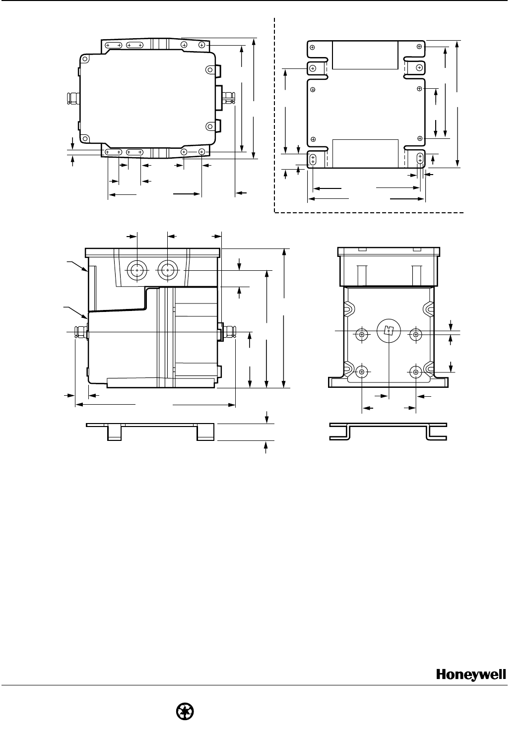
Fig. 1. Dimensions in in. (mm). Note: M9481, M9491 models do not have auxiliary shaft.
All other dimensions are the same.
WIRING
BOX
BASE
MOTOR
AUXILARY
END
POWER
END
ADAPTER
BRACKET
1-1/4 (32)
2-1/2 (64)
1-3/4
(44)
5/32
(4)
3/4 (19)
2-19/32
(66)
5-13/32
(137)
6-7/16
(164)
1-1/2 (38) 2-13/32 (61)
19/32 (15)
4-7/8
(124)
5-1/2
(140)
13/16
(20)
4-1/16 (103)
1/2
(13)
15/16
(24)
9/32
(7)
1-15/32 (37)
7-5/16 (185)
M302G
3/4
(19)
TOP VIEW OF 220738A BRACKET ONLY
3-15/16
(100)
4-7/32
(107)
2-5/16
(58)
5/8
(16)
21/32
(17)
4-7/8 (124)
7/16
(11)
5-17/32 (141)
9/32 (7)
5-13/16
(148)
POWER END
