Rostock MAX V2 User Guide 1st Edition
User Manual:
Open the PDF directly: View PDF ![]() .
.
Page Count: 128 [warning: Documents this large are best viewed by clicking the View PDF Link!]
- Read Me First!
- This document is your instruction manual for your new SeeMeCNC® 3D printer machine. Before using your new 3D printer, thoroughly read and understand this manual for safe and effective operation of the machine.
- 0 – Introduction and Acknowledgments
- 1 – Driver and Software Installation
- 2 – Installing MatterControl and Calibrating the Printer
- 3 – First Print: PEEK Fan Shroud
- 4 – Second Print: Layer Fan Shroud
- 5 – Matter Control Basics: Slicing
- 6 – MatterControl Basics: Loading and Printing Objects
- 7 – Advanced MatterControl: Configuration
- MatterControl includes a number of basic configuration options that you can use to set up things like your default slicing engine, change EEPROM settings, etc.
- Let's go over each one as they appear on the MatterControl Configuration pane.
- MatterControl includes a bed leveling feature that when properly configured, can assist with issues that can arise from an un-level bed. Note that this will NOT calibrate a delta printer! What it can do is help improve first layer performance on an already calibrated printer.
- SeeMeCNC has put together a nice video that illustrates the process quite effectively:
- https://www.youtube.com/watch?v=z6ymbr-AMew
- 8 – Advanced MatterControl: Settings – General
- MatterControl offers three “classes” of settings that have a direct effect on how your printer works. General covers elements that relate to how the plastic is laid down. Filament covers parameters specific to the type of filament that you've chosen to print with. Printer handles those remaining parameters that describe the physical printer you're currently using to print with.
- Let's start this overview on the main page of General, Layers/Surface.
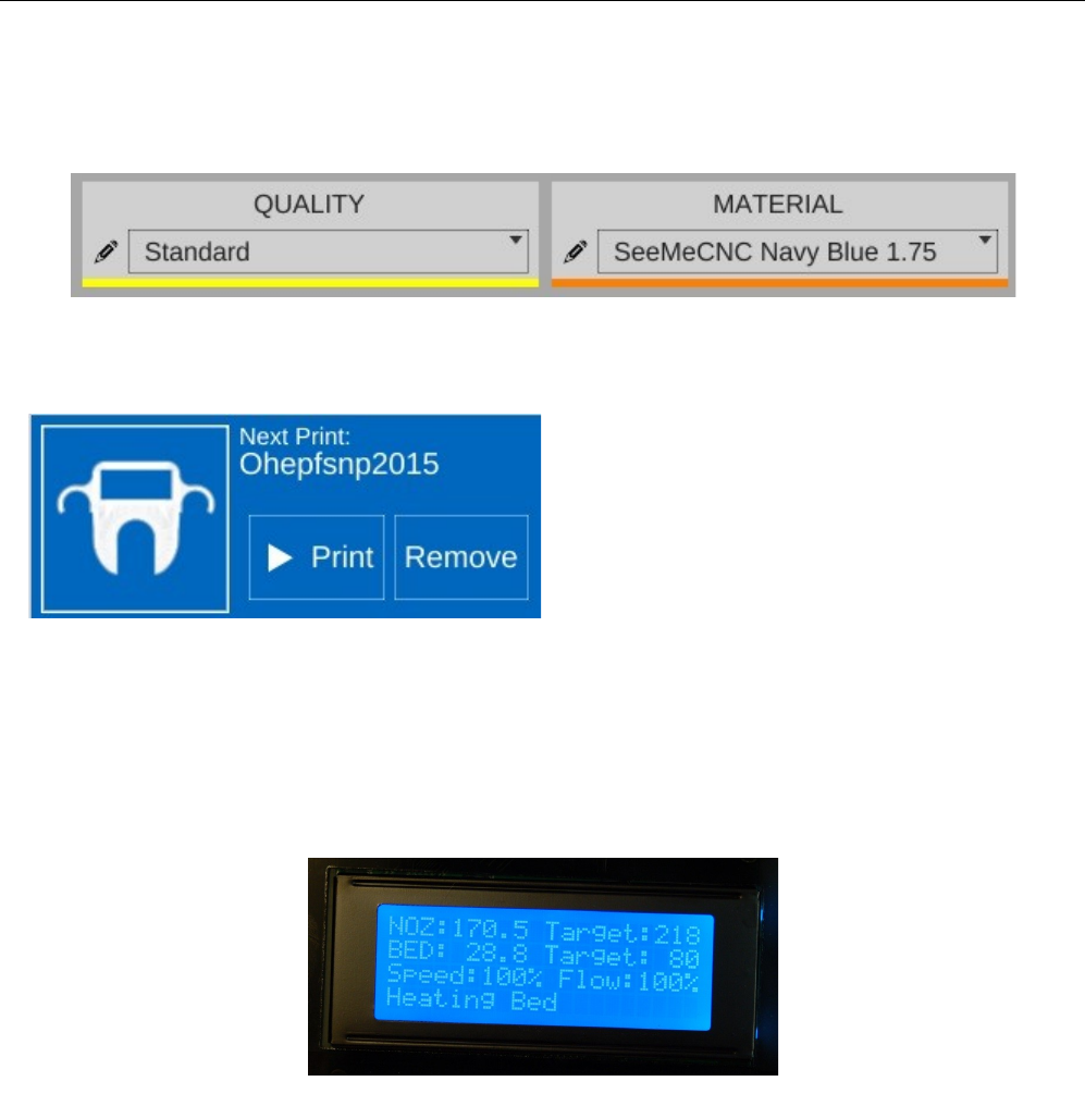
- The first parameter is Layer Height. We've covered this one before, but I wanted to point out something that I didn't go into a lot of detail about earlier. You'll notice that the field has a yellowish highlight to it. That means that the value exists in the currently selected QUALITY profile. If you look carefully, you'll see that the highlight color matches the thin colored line under the QUALITY drop down. (This same effect holds true for MATERIAL profiles, but the color is orange.)
- Any time you add a Print parameter to a preset profile, it will be highlighted just as the Layer Height field is in the example. Note that you can use any of the Print, Filament, or Printer configuration parameters within either of the QUALITY or MATERIAL profile editors.
- The First Layer Height parameter allows you to set the thickness of your first layer. Having a thicker first layer will help provide a good base to build the rest of the part on as the thicker (and thus wider extrusion) will help improve the adhesion to the bed. If your first layer isn't any good, the part could eventually separate from the bed and ruin the print job.
- Bottom Clip allows you to tell the slicing engine that you'd like to “clip off” a specific amount from the bottom of the model. For example, say you've got a 200mm tall model, but you only want to print the top 50mm or so. You can enter 150 into the Bottom Clip field and when the slicer generates the G-Code for the print job, it will begin slicing 150mm up from the bottom of the model.
- Perimeters dictate how thick the “skin” of your model is. 2 or 3 perimeters are good for most parts, but if you want a really strong exterior wall, you can make the perimeter count as high as you feel you need it. To get an idea of how thick the skin will be, you multiply the perimeter count by the extrusion thickness (we'll get to that parameter in a bit). For example, if you have a 0.5mm nozzle, chances are your extrusion thickness will be set to 0.5. 2 perimeters will give you a skin thickness of 1mm. You also have the option of specifying the perimeter thickness in millimeters instead of perimeter counts.
- When Avoid Crossing Perimeters is enabled, the nozzle path will not cross a part perimeter during travel moves. This will help reduce the opportunity for stringing or oozing since the nozzle tip is rarely over open air. For instance, if the tool path would normally cause the nozzle to travel from one side of the part to the other, it would cross at least two perimeters and may leave strings of material in its wake as it moves. If it is set to not cross perimeters, it will cause the nozzle to trace a perimeter back to the nearest point where it can begin printing again instead of jumping straight across to the new extrusion position.
- Spiral Vase mode allows you to print things like vases or other open top, single-wall objects in one continuous layer. What happens is that instead of the slicer raising the nozzle up a full layer height for each new layer, it gradually increases the Z height as the print progresses. This results in a perfectly seamless object, which can be important for artistic prints such as vases. When you're printing a vase or similar object, you'll want to make sure that you set the top layer count to zero to prevent the vase getting a “lid” that you'll have to cut off.
- By default, objects are printed from the inside features to the outside. If you want to reverse this process, enable External Perimeters First. This will cause the outside of the model to be printed before the interior features.
- The Top and Bottom solid layer parameters dictate how thick the top and bottom surfaces of your object are when printed. These two parameters fulfill essentially the same function as the Perimeters parameter, but for the top and bottom of the part. You can calculate your top & bottom thickness by multiplying the solid layer count by the layer height. For example, 5 top layers will result in a final top thickness of 1mm if your layer height is 0.2mm. You also have the option of specifying the top and bottom thickness in millimeters instead of layers.
- The next page in Print is called Infill and covers how the interior of your part is filled. While I covered Fill Density and Infill Type earlier, the Advanced mode adds two new parameters.
- The Starting Angle parameter allows you to control the orientation of the infill. For example, an infill type of GRID with a starting angle of zero degrees is going to look like this:
- Now if you change the starting angle to 45 degrees, you'll end up with an infill pattern that looks like the example below.
- Note that changing the starting angle will also change the angle in which the top and bottom layers are printed. You can see this in the image below – this shows the second layer as it would be printed.
- Infill Overlap is used to adjust how well the infill pattern attaches to the inside perimeter of the part. A good infill will have a solid connection to the inside perimeter of your part, and the structural integrity of your part depends on this.
- The Speed page covers parameters that control how fast various features of the object are printed. The speeds are listed in mm per second, or as a percentage of a related speed parameter.
- The speed parameters are pretty self-explanatory, especially if you've got the Show Help check box set. However, there's a couple of points I'd like to cover about printing speed.
- First of all, there is a relation between your print speed and the temperature you've set for the material you're printing with. The basic rule is, the faster you go, the hotter you print. This is because as the hot end extrudes plastic, it's constantly being cooled by the cold filament that's coming in.
- Setting the extrusion temperature higher allows the hot end to melt the incoming plastic at a faster rate. This allows you to print more quickly. The relation between print speed and extrusion temperature is one of those things you'll get a feel for as you gain experience with your printer.
- You'll quickly learn that the Rostock MAX will “talk” to you if you're printing too rapidly for a given temperature. The extruder will begin to “skip” periodically (or frequently, depending on how fast you're going). A skipping extruder has a very distinct sound – it's kind of a light bump or knocking. If you watch the nylon gear that you use to manually feed filament, you'll notice that it will briefly rotate in the opposite direction at the same time you hear the skipping sound. If you draw a line on the face of the gear, you can spot this motion more easily. The skip is caused by the hot end's inability to melt the material is rapidly as is required. The pressure builds up until the stepper motor can no longer generate the force required. At this point the tension in the filament is released like a spring and the filament pushes back with enough force to cause the stepper motor to skip steps, resulting in a short reverse rotation.
- Secondly, there is also a direct relation between print speed and print quality. In the image above, you'll notice that the speeds for print moves vary a bit. This is because some features don't require a focus on surface quality.
- Perimeters are a great example of this. You'll note that the inside perimeter speed is 40mm/sec, while the outside perimeter is 35mm/sec. The inside perimeter will never been seen after the print is finished so it can be printed at a higher rate. However, you want the visible surface of the print to be smoother and more consistent, so you print the outside perimeters a bit more slowly.
- The last bit about speed settings I want to cover is the first layer speed. You'll see that it's really slow. The reason for this is that while hot plastic loves to stick to hot plastic, hot plastic doesn't like sticking to other things as much. By going slowly on the first layer, you're giving the material time to get a good grip on the surface of the bed. This is known as “part adhesion”. When a part comes unstuck from the bed during a print, it's ruined. This isn't so bad when you're five minutes into a print, but you'll be ready to flip a table when it happens 18 hours into a 19 hour print.
- The Skirt and Raft page covers settings that control how the hot end is primed at the beginning of a print job as well as features that help the part stick to the bed.
- The first section covers the Skirt feature. A skirt in this context is basically a series of single-layer loops printed around the perimeter of the part. This acts as a method to “prime” the hot end with material before the actual part begins to print. Loops defines how many times you want to go around the print. This is tied to the Minimum Extrusion Length parameter. If the number of loops you specify are not enough to meet that minimum length, additional loops will be added automatically.
- The Distance from Object parameter dictates how far away the loop stands off from the part outline. If you set the distance to zero, the skirt will become a “brim”. It will result in the loops being printed connected to the first layer of your print. This can give small parts a first layer that has a larger surface area to improve part adhesion. Since the brim is only a single layer thick, it's usually pretty easy to remove after the print job has completed.
- I mentioned earlier that hot plastic really loves sticking to hot plastic, but not so much to other things. If a brim isn't doing the job for you, you can try a Raft.
- When in Standard mode, the Raft setting was simply an on/off setting. In Advanced mode, you've got a lot more control over how the raft is laid down.
- Expand Distance is the distance you'd like the raft to exceed the base area of the part you're printing. You may want to adjust this parameter if the part you're printing is larger than the bottom contact point on the bed. A larger raft will help to support the part more effectively.
- Air Gap defines how much space you want between the top surface of the raft and the bottom surface of your part. This gap helps make it easier (or even possible!) to remove the raft from your part when it's finished. As mentioned in the help text, a good air gap is one half the diameter of the nozzle. For example, if your nozzle is 0.5mm, you'd want an air gap of 0.25mm.
- You can use the Fan Speed setting to cool the raft as it's being printed. This is typically only used when printing with PLA.
- If you've added a second extruder to your Rostock MAX, you can specify which one should be used for rafts by setting the Raft Extruder value to the index of the extruder you want to use. If you don't have multiple extruders, you can leave this set to zero.
- The Support Material page provides detailed settings on the use of support material if the part you're printing requires it. While I covered the basics of support earlier, I'm going to get a bit more in-depth on it here.
- Checking Generate Support Material will allow you to configure support for your part. Support is required when a part has an overhang or other angled feature that would result in little or no physical support to put a print layer on. The Support Type selection allows you to define the geometric pattern for the support structure. You have GRID and LINES. These patterns were covered earlier, so I won't cover them again here. The new parameter you have to work with in Advanced mode is called Amount.
- Amount is expressed in degrees from vertical and tells the slicing engine to generate support for any feature that meets or exceeds the specified angle. In the setting shown above, the slicing engine will generate support at points where the model “overhangs” 45 degrees or more from vertical.
- When you've got a part feature that's only 20 degrees or so, each layer can easily be supported by the layer underneath. This is because as the part height increases, the horizontal dimension increase is less than the extrusion width. This means that each new layer has a solid foundation to adhere to as it's being applied.
- As you can see when your angle increases to 45 degrees, each layer has much less surface area to adhere to as you print. This is where support comes in handy. It provides that underlying structure for those layers to build upon.
- As the angle increases, the underlying surface area for each layer becomes smaller and smaller until there's simply not enough surface for the next layer to adhere to. In these instances, support material is practically a requirement if you want your part to print at all.
- Now that you've got a good handle on why support can be useful, let's go over the parameters that you can tune to get good support that is easily removable from your part.
- Pattern Spacing controls the distance between each “track” of support that is laid down to support your part. The wider the spacing, the less support that is printed.
- Infill Angle adjusts the angle at which the support structure is built.
- Interface Layers allows you to specify solid layers interspersed with the support material. This comes in handy when using multiple extruders. For example, if you're printing a part in PLA with lots of support, you can generate all the support with PLA, and then have 5 or 6 interface layers of PVA (a water soluble filament). The print would then only be in contact with the PVA interface layers and it would be a flat layer to print on. When finished you can dissolve away the interface layers and the rest of the support falls off the part cleanly.
- X and Y Distance dictates how far away the support structure will be from the part you're printing. You want it as close as you can get it without it actually touching the surface of the part. The default of 0.7mm seems to work out pretty well.
- Z Gap specifies how many layers should separate the support material from the part. This parameter contributes to how easy or difficult it is to remove support material from the part once the print is finished. If you have too little gap, the support material will have more of a grip on the part surface making it difficult to remove. If the gap is too large, the support material won't be able to do its job very effectively.
- If Support Everywhere is checked, you're probably going to get more support material than you bargained for. If you have an internal feature of a part, this may be required in order to support it, but keep in mind that it will also add support to features like horizontally oriented holes, which don't normally need support to print properly.
- If you've got multiple extruders on your Rostock MAX, these parameters allow you to specify which extruder is used for generating support structure.
- The Repair page contains a couple of settings the govern how (and if) the slicer will attempt any repair of invalid part models.
- Sometimes modeling programs will create a model that isn't “water tight”, meaning it's got gaps in the surface. These gaps make it difficult for the slicing engine to do its job and in some cases can cause the slicing operation to fail. The Repair option is MatterSlice's attempt to help fix these issues if they're detected.
- On the Output Options page is a single parameter, Center On Bed. This will automatically center the model on the print bed when you load it. If you don't want that to happen, just un-check the box.
- The Multiple Extruders page has two settings that control how ooze & filament wipes are handled.
- The Wipe Shield Distance specifies how far away from the part you want what is commonly known as an “ooze shield” to be placed around the part. In a two extruder system, the unselected hot end will create this “shield” in order to avoid dripping or oozing plastic on other parts of the model.
- Wipe Tower is used when changing extruders. The active nozzle creates a tower of the specified size and will use it to wipe the nozzle in order to reduce the possibility of oozing or dripping material on the model while the other extruder is active.
- 9 – Advanced MatterControl: Settings – Filament
- 10 – Advanced MatterControl: Settings – Printer
- 11 – Using the 3D and Layer Views
- 12 – A Strategy for Successful (and great!) Prints
- Appendix A: Maintenance and Troubleshooting
- Appendix B: Alternate Calibration Method
- Appendix C: The MatterControl Touch
- Appendix D: Printing From the SD Card
- Appendix E: Optimizing The Temperature Control Algorithms
Rostock MAX v2 User's Guide
Welcome to the User's Guide for the Rostock MAX v2.0 3D printer.
Version 1.52, September 28th, 2016
First Edition
Covers MatterControl v1.4
Copyright 2015 by Gene Buckle
Licensed as Creative Commons Attribution-ShareAlike 3.0
Questions or corrections should be emailed to geneb@deltasoft.com
- 1
Rostock MAX v2 User's Guide
Read Me First!
This document is your instruction manual for your new SeeMeCNC® 3D printer machine.
Before using your new 3D printer, thoroughly read and understand this manual for safe and effective
operation of the machine.
- 2
Warning
Adult supervision required. Children under 18 years of age require supervision.
Risk of Fire. Do not leave machine unattended.
Use genuine parts manufactured or designated by SeeMeCNC.
Keep a copy of this manual near the machine, easily accessible to all operators.
Use of this machine is at your own risk.
Personal property damage, serious injury or death can result from not following
instructions or warning in the manual or misuse of the machine.
Automatic machine can start unexpectedly. Pay close attention and keep clear
while power is connected to the machine
The machine power supply is connected to AC voltage
and can be hazardous. Disconnect power before
servicing this machine.
The hot end of the machine can reach very high
temperatures of 700F and can cause serious burns.
The heated print surfaces (heated bed) can also reach
temperatures high enough to cause severe burns. Allow
both to cool for 20 minutes after turning off power.
Use caution near moving parts of the machine. Keep
body and loose articles clear.
Poisonous gas, smoke, or fumes could be emitted by some materials you could
use with the machine. In such case, you should install ventilation.
Choking Hazard. This machine contains small parts and
can produce small parts which can be a choking hazard
to children.
Visit http://www.seemecnc.com to contact us if you have any questions.
Rostock MAX v2 User's Guide
Table of Contents
READ ME FIRST!.....................................................................................................................................2
0 – Introduction and Acknowledgments....................................................................................................4
1 – Driver and Software Installation..........................................................................................................5
1.1 – Installing the RAMBo Driver..................................................................................................5
1.2 – Installing the Arduino IDE......................................................................................................7
1.3 – Configuring the Arduino IDE..................................................................................................8
1.4 – Test Upload..............................................................................................................................9
1.5 – Uploading Repetier-Firmware...............................................................................................11
1.6 – The LCD and Front Panel Controls.......................................................................................13
2 – Installing MatterControl and Calibrating the Printer.........................................................................16
2.1 – Downloading, Installing, and Configuring MatterControl....................................................16
2.2 – Initial Function Tests.............................................................................................................22
2.3 – Setting the Z Height...............................................................................................................27
2.4 – Motion Calibration.................................................................................................................29
2.5 – Verifying Extruder Stepper Operation...................................................................................32
2.6 – Extruder Calibration..............................................................................................................32
3 – First Print: PEEK Fan Shroud............................................................................................................34
3.1 – Configuring the Slicer............................................................................................................34
3.2 – Printing The PEEK Fan Shroud.............................................................................................36
3.3 – Loading Filament...................................................................................................................37
3.4 – Preparing the Heated Bed......................................................................................................38
3.5 – Printing the PEEK Fan Shroud..............................................................................................39
3.6 – Installing the PEEK Fan and Shroud.....................................................................................41
4 – Second Print: Layer Fan Shroud........................................................................................................44
5 – Matter Control Basics: Slicing...........................................................................................................47
6 – MatterControl Basics: Loading and Printing Objects........................................................................61
7 – Advanced MatterControl: Configuration...........................................................................................67
8 – Advanced MatterControl: Settings – General....................................................................................71
9 – Advanced MatterControl: Settings – Filament..................................................................................81
10 – Advanced MatterControl: Settings – Printer....................................................................................85
11 – Using the 3D and Layer Views.........................................................................................................88
12 – A Strategy for Successful (and great!) Prints...................................................................................97
Appendix A: Maintenance and Troubleshooting....................................................................................110
Print Layer Issues..........................................................................................................................111
Machine Won't Move!...................................................................................................................113
LCD Panel Not Working...............................................................................................................113
Appendix B: Alternate Calibration Method...........................................................................................115
Appendix C: The MatterControl Touch.................................................................................................119
Appendix D: Printing From the SD Card...............................................................................................126
Appendix E: Optimizing The Temperature Control Algorithms............................................................127
- 3

Rostock MAX v2 User's Guide
0 – Introduction and Acknowledgments
I’d like to welcome you to the 1st Edition of the Rostock MAX v2 User's Guide!
Acknowledgments
I'd like to thank the gentleman that runs http://minow.blogspot.com.au/ for his excellent guide
on calibrating delta configuration 3D printers.
I'd also like to thank the whole gang over at the SeeMeCNC forums for providing excellent
feedback. This would be a much lesser creation without their contributions and insights.
0 – Introduction and Acknowledgments - 4

Rostock MAX v2 User's Guide
1 – Driver and Software Installation
The Rostock MAX v2 does not include the firmware required to operate it. This was a
conscious decision by SeeMeCNC to encourage builders to become more proficient in the operation of
their new 3D printer.
Downloading the tools necessary to build and upload Repetier-Firmware is simple and easy.
However, before you get to that point, you're going to need to install a driver in order to communicate
with the RAMBo controller. If you're using MacOS or Linux, you can skip the driver installation
instructions.
1.1 – Installing the RAMBo Driver
Download the USB Driver zip file from this location:
http://download.seemecnc.com/Software/RAMBo_USBdriver.zip
The driver will work with all versions of Windows – XP to v8.1.
If you haven't done so already, connect the Rostock MAX to your computer using the included
USB cable and turn the Rostock MAX on using the power switch you installed previously.
Unzip the file to a temp directory or other place that you know the location of. For Windows
users (and likely XP, Windows 8 and Vista users as well), plug in the RAMBo and let Windows “fail”
to find the correct driver for the board. Open up the device manager by right-clicking on “Computer” or
“My Computer” and select “Properties” followed by “Device Manager”. Scroll down to the “Unknown
Devices” entry and right-click on the RAMBo entry. Choose “Update Driver” and then “Browse my
computer for driver software” (or something similar to this). Choose “Let me pick from a list of device
drivers on my computer”, then click the button for “Have Disk”. Browse to where you unzipped the file
you downloaded and then click “OK”. It may complain (depending on OS) that the driver isn’t signed –
allow it to install it anyway. That’s all there is to it. The RAMBo will now appear on your computer as
a standard serial port. On my computer it appeared as COM10 – it will most likely be different on
yours.
1 – Driver and Software Installation - 5
Rostock MAX v2 User's Guide
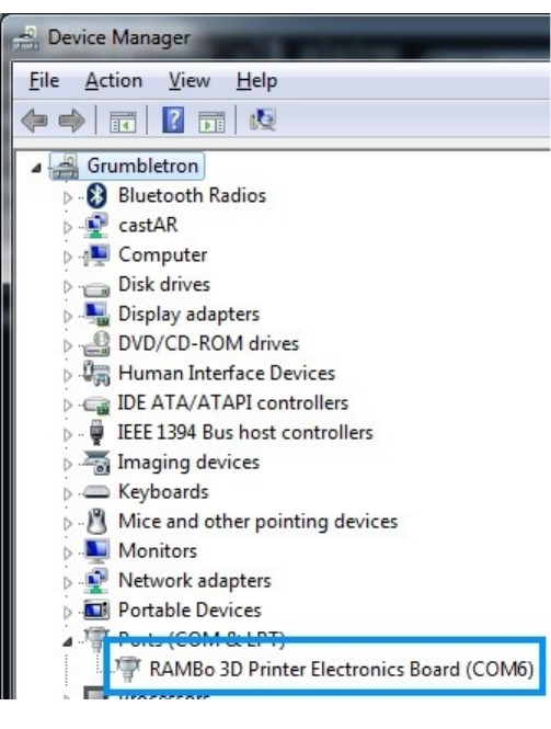
The easiest way to find out what port your RAMBo is listening on is to open up the Device
Manager and look for the RAMBo entry. In order to discover this bit of information, you'll need to
open up Device Manager (right click on My Computer, click “Properties” and then click “Device
Manager”). You'll get a window that looks something like this:
The entry we're looking for is highlighted
in green. Your “COM” entry will more than likely
be different from mine. Write this entry down as
you'll need it very soon.
1 – Driver and Software Installation - 6
Fig. 1.1-1: The RAMBo in the Device Manager
Rostock MAX v2 User's Guide
1.2 – Installing the Arduino IDE
In order to compile and upload the firmware to the RAMBo controller, you're going to need the
Arduino IDE. This is an open source software development environment targeted at the Arduino
family of ATMega-based microcontroller project boards. At its heart, the RAMBo controller is just an
Arduino Mega 2560 with a lot of goodies attached to it.
You can download the Windows, MacOS and Linux version of the Arduino IDE from here:
http://arduino.cc/download
The version of the IDE used as of this writing is 1.6.1, but later versions can be used.
Install the Arduino IDE using the downloaded installer.
Now you need to download the firmware from SeeMeCNC's github repository.
https://github.com/seemecnc/Firmware/archive/master.zip
Unpack the “master.zip” file that you downloaded into a directory where you can keep track of
it. You may need to reference it in the future.
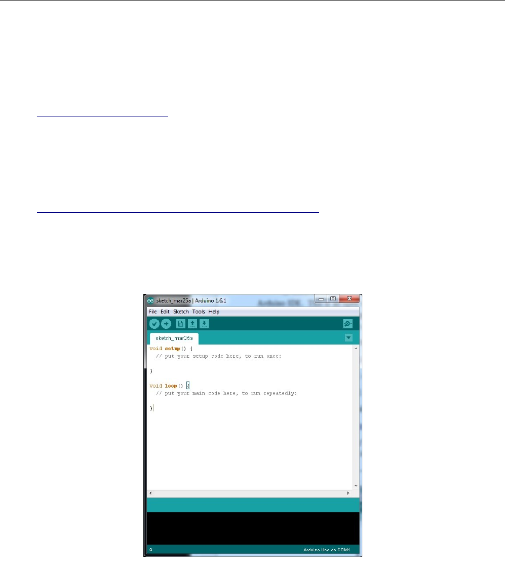
Start the Arduino IDE – you should be presented with a screen that looks similar to this:
1 – Driver and Software Installation - 7
Fig. 1.2-1: The Arduino IDE
Rostock MAX v2 User's Guide
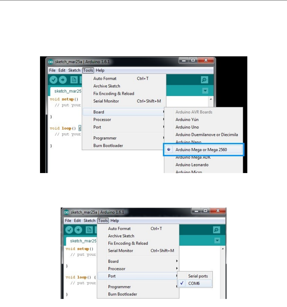
1.3 – Configuring the Arduino IDE
Before we can use the IDE to upload the firmware to the RAMBo controller, we need to tell the
Arduino IDE what kind of board we have and what communications port it needs to use in order to
perform the upload task.
Click on the “Tools” menu item and then click on “Board” and then “Arduino Mega or Mega
2560”.
Next, you'll need to tell the Arduino IDE what port to talk to the RAMBo on. To do this, click on
“Tools”, “Serial Port” and then choose the COM port that your RAMBo appears as on your computer.
1 – Driver and Software Installation - 8
Fig. 1.3-1: Choosing the board type.
Fig. 1.3-2: Choosing the Serial Port.
Rostock MAX v2 User's Guide
1.4 – Test Upload
Ok, now that you've got the Arduino IDE configured, we're going to do a quick task that'll do
two things. First, it will validate that you've got the Arduino IDE configured properly and that you're
able to connect and upload a program to the RAMBo controller. Remember – the RAMBo controller is
just an Arduino Mega 2560 with a bunch of goodies piled on top!
Second, the program I'm going to have you run will clear the EEPROM on the RAMBo
controller to make sure you start with a clean slate. The EEPROM is an Electrically Erasable
Programmable Read Only Memory and it's where Repetier-Firmware will store settings. When you can
store configuration information in the EEPROM, it means that you don't have to re-upload the
firmware every time you make a change.
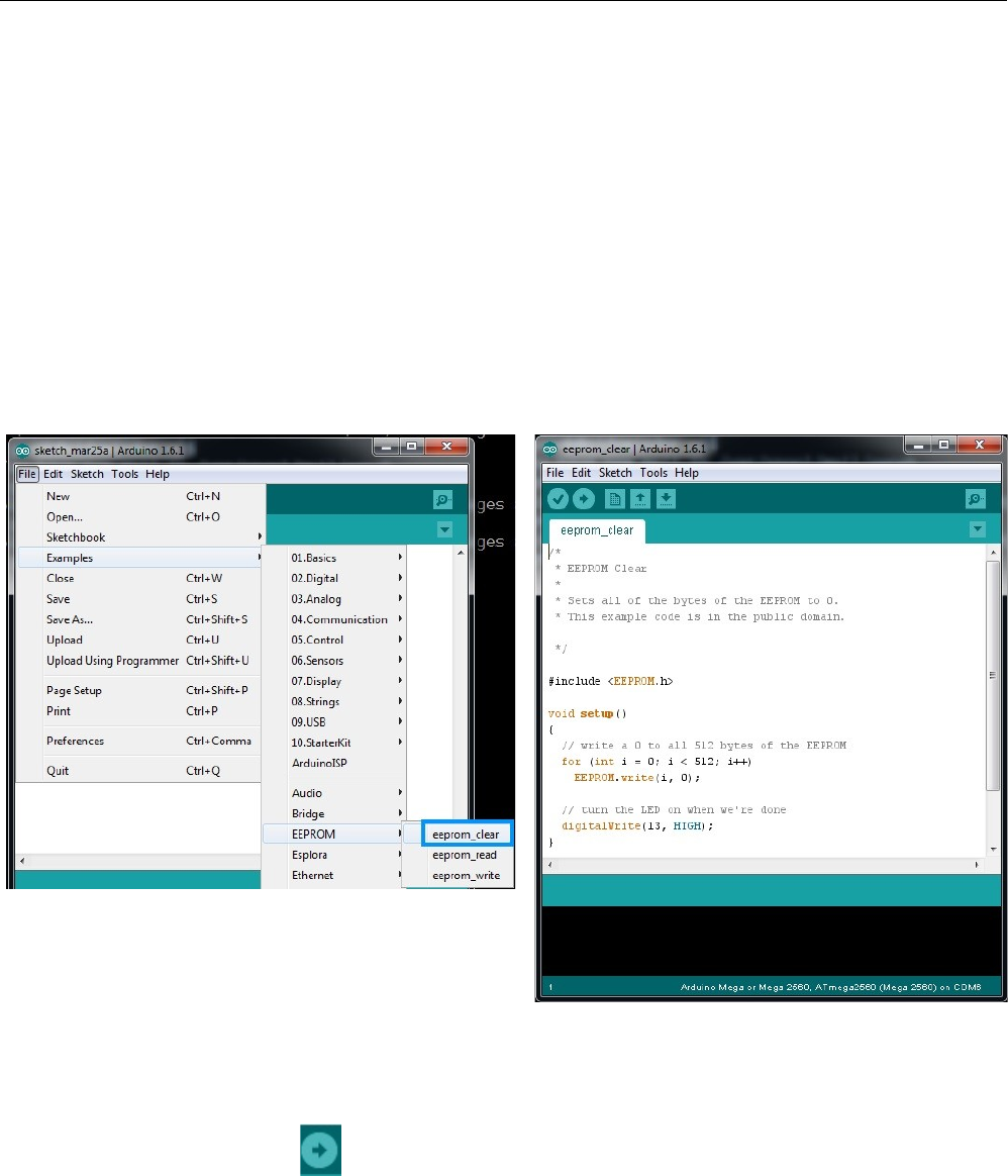
Click on “File”, “Examples”, “EEPROM”, and finally “eeprom_clear” as highlighted in blue in
the figure below.
The only thing you need to do now is click the “Upload” icon in the Arduino IDE. The upload icon is
represented by this symbol:
1 – Driver and Software Installation - 9
Fig. 1.4-1: Loading the eeprom_clear program.
Fig. 1.4-2: eeprom_clear loaded & ready to go.
Rostock MAX v2 User's Guide
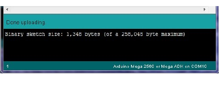
Turn your Rostock MAX v2 on if you haven't already and then click the Upload icon.
When the upload is finished, you should see
results similar to that on the right. The “Done
uploading” is the status you want. There is no other
external evidence that the eeprom_clear program has
done its job, but it has!
1 – Driver and Software Installation - 10
Fig. 1.4-3: Success!
Rostock MAX v2 User's Guide
1.5 – Uploading Repetier-Firmware
Now it's time to load Repetier-Firmware into the Arduino IDE and upload it to the RAMBo
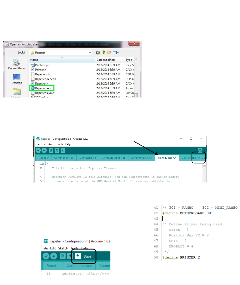
controller! Click “File”, “Open” and browse to where you unpacked the master.zip file you
downloaded from the SeeMeCNC github repository. Select the file “Repetier.ino” and click the Open
button. Note that Windows may hide the program suffix (.ino) from you.
Before you can upload the firmware to the RAMBo, you're going to need to make two small
changes to how the firmware is configured. Once you have the firmware loaded in the Arduino IDE,
click on the tab marked Configuration.h.
Now scroll down a short way until you see the section that matches the figure below.
You'll need to make sure that the MOTHERBOARD
definition is set to “301” for the RAMBo board and the
PRINTER option is set to “2” for the Rostock MAX v2. Click
on the Save icon to save your changes.
1 – Driver and Software Installation - 11
Fig. 1.5-1: Opening Repetier.ino
Fig. 1.5-2: The Configuration.h tab in the editor.
Fig. 1.5-3: Configuration options.
Fig. 1.5-4: Save changes!
Rostock MAX v2 User's Guide
Now you can click on the Upload icon to send the firmware to the RAMBo!
Depending on the speed of your computer, this could take up to a few minutes to accomplish.
Be patient and wait for the “Done uploading.” status to appear just like it did when you uploaded the
“eeprom_clear” program.
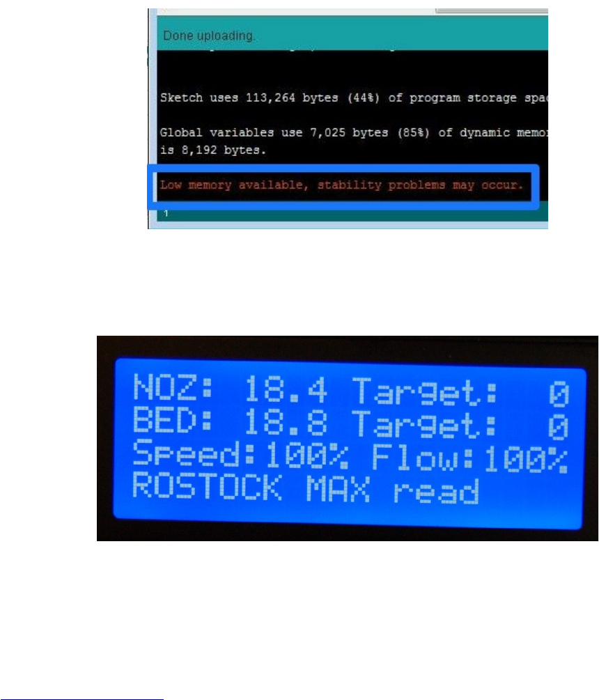
You may see a warning similar to the one shown below. This is strictly an advisory message
and won't affect how the firmware works with your Rostock MAX.
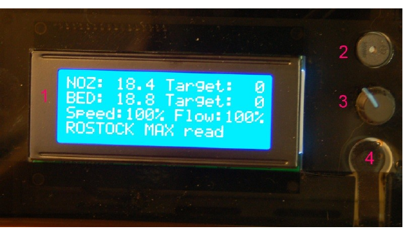
When the upload has finished the RAMBo will restart and you should see the following display
on the LCD:
Congrats again! You've got a living, breathing (hey, work with me here!) 3D printer that you've
built yourself. If for some weird, inexplicable reason you do NOT see that display (or something very,
very similar!), carefully retrace your steps. Start back at the beginning with the eeprom_clear test and
go from there. If you still don't get a working display please check Appendix A, or contact
support@seemecnc.com!
1 – Driver and Software Installation - 12
Fig. 1.5-5: It's ALIVE!
Fig. 1.5-5: Compiler advisory message.

Rostock MAX v2 User's Guide
1.6 – The LCD and Front Panel Controls
Let's go over what information the LCD displays and what the front panel controls do.
1. Nozzle Temperature. This is the temperature at the nozzle as measured by the thermistor
that you installed when you put the hot end together. It reads in degrees Celsius – you'll
find quickly that just about everything to do with 3D printing is done in Metric units of
measure. FYI, 18.4C is 65.12F.
2. Target Nozzle Temperature. When you're printing a part, this field will show you what
temperature you've set the hot end to.
3. Bed Temperature. This is the temperature of the Onyx heated bed as measured by the
thermistor that you installed in the center of the bed. Just like the nozzle, it reads in
Celsius.
4. Target Bed Temperature. This displays the temperature that you've set the Onyx to heat
to.
5. Speed Rate. This is the speed multiplier field. Normally it will read 100%, but if you've
changed the speed control from MatterControl, this number will display what that
setting is. We'll get into this in more detail later.
6. Flow Rate. This shows the current flow rate of the extruder. This is also a field that is
controlled from MatterControl.
7. Status Line. This is a multipurpose display field that will change depending on what the
printer is currently doing.
1 – Driver and Software Installation - 13
Fig. 1.6-1: Default LCD display.
Rostock MAX v2 User's Guide
The front panel:
1. The LCD Display. (but you knew that, right?)
2. Beeper. That's it does. Beeps. (and beeps, and beeps and beeps...)
3. Input Controller. Turning the knob clockwise & counter clockwise is how you navigate
through the LCD menus. Pressing the button straight in acts similarly to a mouse click –
it selects the current menu item.
4. Emergency Reset Button. When you hit that button, a number of things are going to
happen. First, the RAMBo is going to turn off both the heat bed and the nozzle heaters.
Next, it's going to send all three Cheapskates to their “home” positions at the top of the
Rostock MAX v2 and then the RAMBo controller will reboot itself. If the printer is
really going nuts on you, this is the second fastest way to make it behave. (The first is to
turn the power off!)
Note that in order to operate the reset button, you need to press hard. You'll hear it
click, but that's kind of deceptive. The button doesn't close until more force is applied to
the little reset button arm. It is somewhat of a safety feature to prevent accidental resets
during a print job.
1 – Driver and Software Installation - 14
Fig. 1.6-2: The Front Panel.
Rostock MAX v2 User's Guide
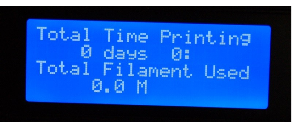
The last thing I'm going to cover in this section is the “activity” display that the LCD can show
you. Turn the knob either direction and you'll get a display that looks something like this:
This will tell you at a glance how much time your Rostock MAX v2 has spent printing and how
much filament it's used in the process. The time display breaks down into days, hours and minutes.
The filament display shows filament used in fractional meters.
Now let's get this thing calibrated and printing!
1 – Driver and Software Installation - 15
Fig. 1.6-3: Activity display.
Rostock MAX v2 User's Guide
2 – Installing MatterControl and Calibrating the Printer
This is the fun part! The Rostock MAX v2 3D printer is very easy to calibrate, but it can take
some time and a number of iterations to get it as good as you can. You'll want to take your time here
because the better you calibrate the printer, the better it will perform.
2.1 – Downloading, Installing, and Configuring MatterControl
The “host” software of choice for the Rostock MAX is called MatterControl.
MatterControl is a full featured and multi-platform host interface for 3D printers. There are
other host interfaces out there such as Octoprint, Repeiter-Host, and Pronterface, but this guide will
only cover MatterControl. MatterControl is available for Windows and MacOS platforms. If you've
got a Linux machine, you'll want to look into either Pronterface or Repetier-Host.
MatterControl can be downloaded from http://seemecnc.com/pages/downloads. Scroll down to
the “Software” section.
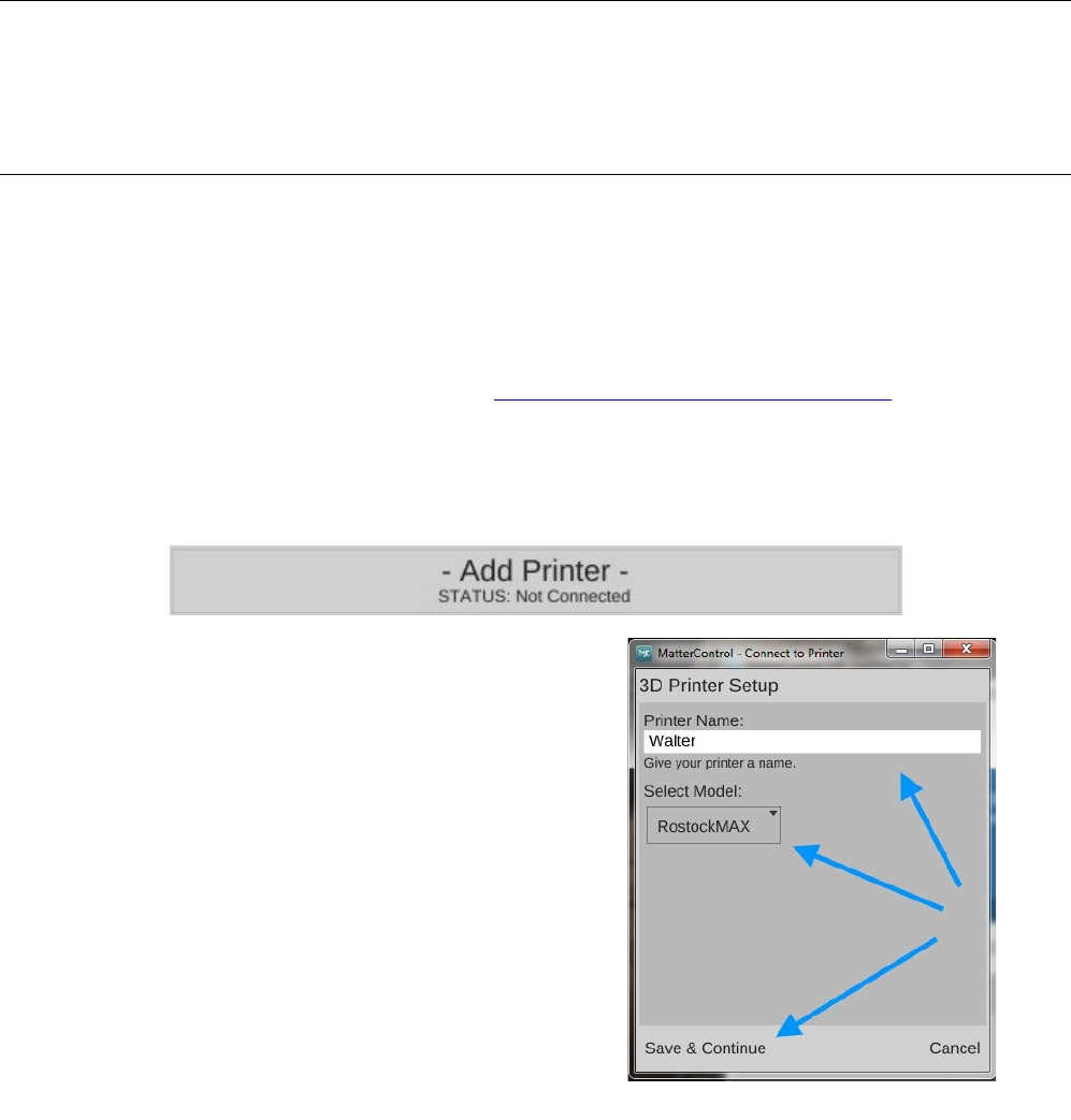
After the download completes, run MatterControl and click on “Add Printer” button as shown
below. This will open a dialog box that you'll use to select your printer model and give it a name.
Click in the “Printer Name” field and enter a name
for your Rostock MAX v2 3D printer. I've named mine
“Walter”. (Yes it's weird. I'm weird. Deal with it.)
Select “RostockMAX” from the “Select Model”
drop-down.
Note that since you're using the SeeMeCNC
customized version of MatterControl, the model drop-down
will only contain the models of SeeMeCNC made printers
as well as “Other” if you'd like to configure MatterControl
to use a non-SeeMeCNC printer in the future.
Click the “Save & Continue” button to continue.
2 – Installing MatterControl and Calibrating the Printer - 16
Fig. 2.1-1: Printer setup.
Rostock MAX v2 User's Guide
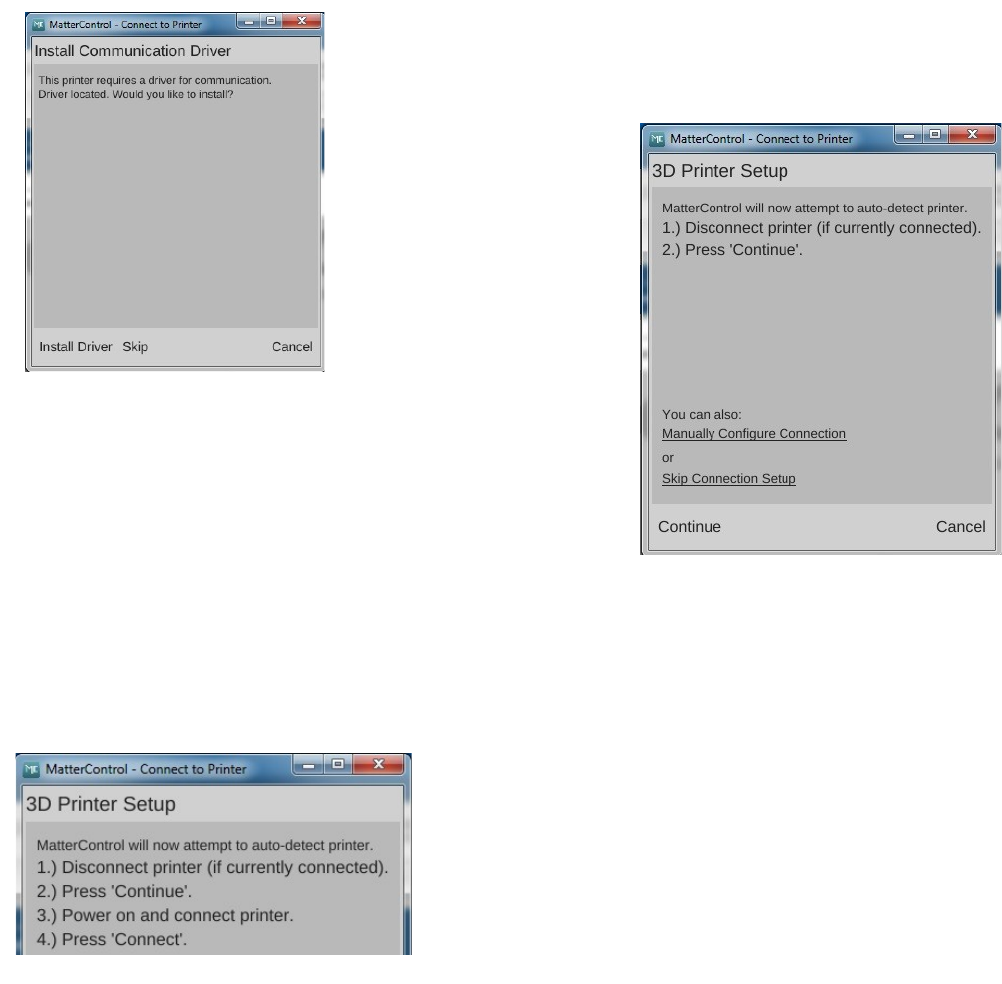
When you save the new profile, you'll be prompted to install a driver. Since you've already
installed the RAMBo driver to load the firmware on your new Rostock MAX v2, you can safely click
“Skip”.
When the new printer configuration is saved,
MatterControl will then try to auto-detect the printer. It does this
by attempting to interrogate printers on each serial port present on
your computer.
MatterControl can detect what kind of firmware it's
talking to based up on the response it gets for this step.
The dialog shown on the right is a bit unclear – the
MatterControl guys are assuming that you might have gotten
ahead of yourself. If you DID connect MatterControl (using the
CONNECT button), go ahead and click the DISCONNECT button and then bring the 3D Printer Setup
dialog to the front by clicking on it in the task bar.
Go ahead and click the Continue button. You'll be presented with a new dialog as shown below
on the left.
Make sure you've got the USB cable connected to
the RAMBo and your computer. Power on your Rostock
MAX v2 and then click the “Connect” button.
2 – Installing MatterControl and Calibrating the Printer - 17
Fig. 2.1-4: 3D Printer Setup.
Fig 2.1.-2: Driver dialog.
Fig. 2.1-3: Connecting to the printer.
Rostock MAX v2 User's Guide
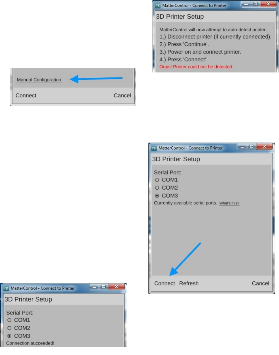
If for some reason MatterControl cannot “see”
the Rostock MAX v2, you may see an error like the
one shown on the right.
If you do get this error, click on the “Manual
Configuration” link at the bottom of the dialog box.
The Manual Configuration link will bring up a dialog box that allows you to choose which
communication port your printer is connected to.
You'll be presented with a list of the serial
ports that MatterControl can currently “see”. If you
don't see any ports, or the one you need isn't listed,
then click the “Refresh” button at the bottom of the
dialog. If the port STILL does not appear, check to
make sure that the USB cable to the Rostock MAX
v2 is correctly connected and the printer is turned on.
If you still see no port after clicking Refresh, please
contact SeeMeCNC support!
If your port is listed, click on the little circle
to select it and then click the “Connect” button at the
bottom of the dialog. You should be rewarded with
the following dialog:
2 – Installing MatterControl and Calibrating the Printer - 18
Fig. 2.1-5: Oops!
Fig. 2.1-6: Manual Configuration
Fig. 2.1-7: Serial port selection
Fig. 2.1-8: Success!
Rostock MAX v2 User's Guide
Click the “Done” button and let's continue!
Maximize the MatterControl window to see the entire main screen. If you shrink the size of the
main window, features “fold” away to keep from cluttering the display. It's actually pretty clever.
Before we get to the details of getting your printer calibrated, let's cover what features are
available from MatterControl. Because the MatterControl display does contain so much information,
I'm going to break it down into smaller segments to make the screen shots easier to see as I describe the
various components in MatterControl.
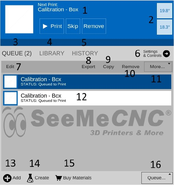
1. This is the print queue display. If
nothing is queued up, you'll see the
message, “No items in the print
queue”. To add an item, click the
“Add” button (#13). We'll cover this
in detail later. Note that you can
only select STL or GCODE files.
2. This is the temperature display. The
top number displays the current
nozzle temperature and the bottom
number covers the heated bed. Both
temperatures are displayed in
degrees Celsius.
3. Queue count. This lists the number
of objects currently loaded in the
print queue.
4. Library – this is a list of items that
you've stored in your object “library”. We'll cover this one in detail later as well.
5. Print History – Clicking here will show you information about your recent print jobs, including
their start & end times as well as whether or not the job was completed.
6. Settings & Controls – this is where you can edit your slicer & printer settings as well as
manually control your Rostock MAX v2.
7. The Edit button will allow you to choose which items in the print queue will be available for
printing.
8. The Export button will allow you to export the currently select item as an STL, AMF, or
GCODE file. You can use this to save GCODE to an SD card for stand-alone printing
2 – Installing MatterControl and Calibrating the Printer - 19
Fig. 2.1-9: Status & Print Queue Pane.
Rostock MAX v2 User's Guide
9. The Copy button will make copies of the currently selected item in the print queue.
10. The Remove button will remove the currently selected item in the print queue.
11. The More drop-down will allow you to send the currently selected item to another device, or to
the print Library.
12. This is where you'll see items that are currently in your Queue.
13. The Add button will allow you to add objects or G-Code files to the print queue.
14. The Create button displays a list of available plug-ins that are used to create printable objects
right inside of MatterControl.
15. The Buy Materials button will open a browser and point it to the SeeMeCNC store.
16. The Queue button opens a menu list that will allow you to export the current file and perform
other operations on the print queue.
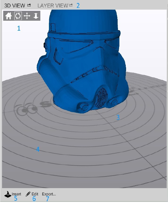
The right half of the MatterControl
interface is occupied by a 3D view of your
build platform and what objects are
currently loaded and ready to print.
1. View manipulation controls – Reset
View, Rotate, Pan, and Zoom. By default,
the 3D view will show a rotating display of
the part. You can stop the rotation by
clicking anywhere in the 3D view window.
2. The 3D and Layer view controls allow
you to switch between the 3D view
(shown) and the Layer view. The layer
view shows you the path the print head will
take as your part is printed. The layer view
won't display anything until the part you
want to print has been “sliced”.
3. The object currently ready to print.
4. This is a representation of your Rostock
MAX v2's print bed. As long as your
object fits within the circle, you should be
able to print it!
2 – Installing MatterControl and Calibrating the Printer - 20
Fig. 2.1-10: The Model Pane
Rostock MAX v2 User's Guide
5 & 6. The Insert and Edit buttons allow you to add objects to the current print job as well as
manipulate them.
7. The Export button allows you to save the current state of the build plate in a few different file
formats. This feature will allow you to save GCODE to the SD card for stand-alone printing!
Go ahead and click on the Settings
& Controls button. The Settings &
Controls pane allows you to directly
control your printer, change its
configuration and change slicer settings.
The image on the right shows the
“Controls” portion of the display. (If you
look at the top, you'll notice
“CONTROLS” is highlighted.)
There's a lot going on with this
pane, so I'll go into more detail with it as
you need to use it as well as in a later
chapter.
Let's move on to getting your
printer ready to calibrate!
2 – Installing MatterControl and Calibrating the Printer - 21
Fig. 2.1-11: The Settings & Controls Pane.
Rostock MAX v2 User's Guide
2.2 – Initial Function Tests
Before the calibration process can begin, we need to perform a test of the end-stop switches to
make sure that they're functioning correctly. In order to perform this test, you'll need to be able to
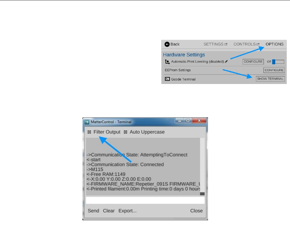
directly “talk” to the Rostock MAX v2. Click on the Options button as indicated below.
Click on the SHOW TERMINAL button. This
will open up the terminal screen that we need to use to
directly communicate with the printer. When the
terminal window first opens, you'll see it displaying
information that's coming from the printer. This data is
being processed by MatterControl to update the
temperature displays, etc. The terminal is easier to work with if we turn that information off. To do so,
click on the Filter Output check-box as shown below.
Now we can send the commands necessary to test the end stop switches. It's important that they
operate properly as they're used by the printer to determine the “home” position for the three towers.
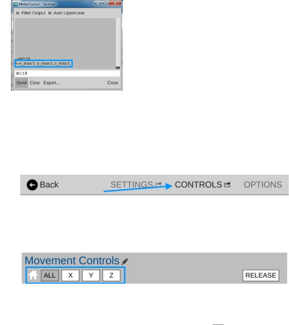
Ensure that the end-stop adjustment screws are not in contact with the switches and then enter
“M119” into the terminal input box and press the ENTER key.
The M119 command instructs the RAMBo board to return the current state of the three end stop
switches.
2 – Installing MatterControl and Calibrating the Printer - 22
Fig. 2.2-2: Filtering the terminal output.
Fig. 2.2-1: Terminal on the Options pane.
Rostock MAX v2 User's Guide
The three switches are known as “x_max”,
“y_max”, and “z_max”. Each one should have an “L”
next to it as shown on the left. If any of them show an
“H”, check your wiring to ensure that the switch is
connected properly at both ends. The printer will not
operate properly if any of the end-stop switches are
reporting “closed” when they're not.
An “L” next to each label indicates that all three end-stop switches have not been pressed. If
you see anything different, please check your wiring as mentioned previously! Now I want you to hold
down the switch lever for the X axis and re-send the M119 command. You should see the x_max value
change to “H”. Do this for the Y and Z axes. This will ensure the end stop switches are functioning –
this is very important for the next step!
Click the CONTROLS button to get to the screen where we'll perform the movement tests.
The next test we're going to perform involves making sure that the stepper motors on the towers
are wired correctly. Every once and a while we'll see a stepper motor with the connector wired
correctly, but the internal wiring is backwards. Maybe the elves that build stepper motors were having
a bad cookie day or something. Let's find out if you won a bad cookie motor!
The next task is to make sure that you can “home” the machine. By clicking on the ALL button
shown above, it should send all three axes up to the end-stop switches.
With one finger on the power switch, click that ALL button! If any of the three axes do not
head up to the top of the machine, turn off the power immediately! You don't want to do any damage
to the machine due to an inverted axis. Don't worry though, fixing an inverted axis is VERY easy!
If you need to apply this fix, click the DISCONNECT button in MatterControl and then open
up Repetier-Firmware in the Arduino IDE. Click on the tab marked “Configuration.h”. You may need
to increase the width of the IDE window in order to see that tab.
2 – Installing MatterControl and Calibrating the Printer - 23
Fig. 2.2-4: To the Controls pane!
Fig. 2.2-5: Home Axes.
Fig. 2.2-3: Testing the end stop switches.
Rostock MAX v2 User's Guide
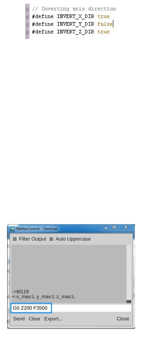
Scroll down until you find a small section marked “// Inverting axis direction”.
Once you've located this area, I want you to change the entry that corresponds to your
misbehaving motor to the opposite of its current setting. If it's currently true set it to false and vice-
verse. If you have more than one, change those as well. For example, if your Y axis Cheapskate
headed for the floor when you hit the reset button, you'll change INVERT_Y_DIR to true. Once
you've made your changes, click “File”, “Save” and then hit the Upload icon to send your updated
firmware to the RAMBo controller.
Once the upload finishes, click the CONNECT button in MatterControl to reconnect to the
printer. You'll need to click on the Advanced Controls button in order to return to the control screen.
The next test involves moving the axes around to make sure they're free and clear and there's no
“bad” noises going on. Make sure that you're on the CONTROLS screen and hit the Home All icon
line you did before. All three axes should travel to the top of the machine and “bounce” off the end
stop switches.
Click the OPTIONS button and then click the SHOW TERMINAL button.
Send “G0 Z200 F3500”. This will move the effector platform down a few centimeters. The
idea is to get them off the end stops so we can move things around a bit.
2 – Installing MatterControl and Calibrating the Printer - 24
Fig. 2.2-6: Axis directions.
Fig. 2.2-7: Getting some room to move!
Rostock MAX v2 User's Guide
Close the terminal window and click on the CONTROLS button to return to the control screen.
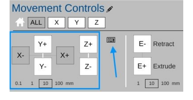
The manual travel controls (outlined in blue, above) will allow you to manually move the
effector platform around the operating area. The X axis buttons will move the effector platform to the
left (X-) and right (X+). The Y axis buttons will move the Y axis toward the front of the machine (Y-)
and toward the back of the machine (Y+). The Z axis buttons will raise (Z+) and lower (Z-) the
effector platform.
The arrow points to a keyboard symbol. When you click on that symbol, you can use your
cursor keys to move the effector around just as you did by clicking on the labeled buttons. The Up and
Down arrows control the Y axis, the Left & Right arrows control the X axis and the Page Up and Page
Down keys control the Z axis.
Under the axis controls you'll see four values with a square box around the “10” value. These
values dictate how much to move the effector platform with each click of an axis button. The values
are in millimeters. The “.1” value will set the travel distance to 0.1mm and the “100” value will set the
travel distance to 100mm.
Experiment with how the machine moves by clicking on the axis controls or use the cursor
keys. Be careful not to drive the hot end outside the boundaries. If you accidentally do that, just power
the machine off and back on. Click the DISCONNECT button and then hit CONNECT to re-establish
communication between the Rostock MAX v2 and MatterControl. You'll need to re-home the machine
before you continue experimenting.
While learning how the motion controls work, please keep the Z height (the distance from the
tip of the hot end to the build surface) a few inches above the build platform. We haven't set the
Rostock MAX's true Z height yet and you don't want to smash the hot end into the bed by accident.
2 – Installing MatterControl and Calibrating the Printer - 25
Fig. 2.2-8: Manual travel controls.
Rostock MAX v2 User's Guide
The last test involves checking the basic function of both the hot end heating resistors and the
heated bed. For this test, you're only going to turn them on long enough to verify that they're indeed
heating up as they should.
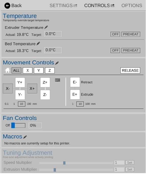
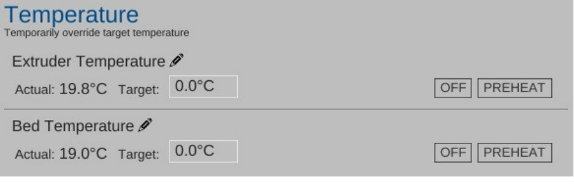
We'll test the hot end first. In the Extruder Temperature Override section, click in the
“Target:” box (where it reads 0.0) and type in “200” and press ENTER or click on the SET button that
appears when you begin typing in the field.
Once you see the “Actual” temperature (“19.8C” above) begin to climb, wait a few seconds
and the click the OFF button to turn it off. Perform the same test with the heated bed by setting the
target temperature in the Bed Temperature Override to 50. Note that because the bed has such a large
surface area, it will heat much more slowly than the hot end.
You'll notice that after you turn the heaters off that the temperature will continue to climb for a
short time. This is normal behavior. It' just like a burner on a stove. When you turn it on for a short
time and turn it off again, it'll still continue to heat for a short time until the surrounding air can cool it
down. As the bed heats, you should see the “BED HEAT” LED illuminate. If it doesn't and you see
the bed heating on the LCD, check the polarity and wiring of the LED.
Okay, now that you've spent the last 5 minutes (Who am I kidding? You've been poking at it for
at least an hour, giggling like a little kid. Your dignity is the first casualty of having your own 3D
printer. Don't worry, you're in good company.) moving the hot end around and seeing how it works,
now it's time to get it calibrated so you can begin printing your army of squirrels and Yoda heads!
In order for the mechanical calibration to be accurate, we need to do the steps with the Rostock
MAX at operating temperature. This means that both the hot end and heated bed must be at the
temperature they'd normally be at while printing.
2 – Installing MatterControl and Calibrating the Printer - 26
Fig. 2.2-9: Manual temperature controls.
Rostock MAX v2 User's Guide
2.3 – Setting the Z Height
Bring your hot end and heated bed up to operating temperature. Set the hot end temp to 190C
and the heated bed to 55C. We want the hot end and bed to expand to “normal” so we can get a fairly
accurate measurement here.
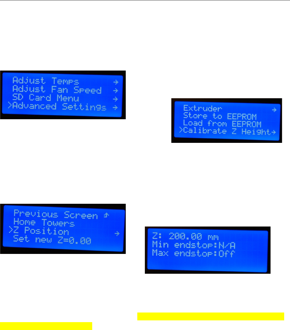
Once the hot end and bed have reached their target temperatures, push the knob in on the LCD
controller. This will take you to the LCD menu. Turn the shaft counter-clockwise until you reach the
“Advanced Settings” entry and then click the button to select that option.
Rotate the shaft counter-clockwise until you reach
the “Calibrate Z Height” option and click the
button.
Rotate the knob counter-clockwise again and choose the “Home Towers” menu option and
click. This will send the Rostock MAX to the home position. This is the same as sending G28 to the
printer or clicking the “Home All” icon in MatterControl. After the homing process finishes, select the
“Z-Position” option and click.
When you click on the Z-Position option, you'll
see a display similar to that shown below.
You control the height of the effector platform by turning the shaft on the LCD panel. Turning
it counter-clockwise will lower the nozzle, and turning it clockwise will raise it.
If you turn the shaft quickly, you'll get large changes and if you turn it slowly, one step at a
time, the change will only be 0.01mm per click. Please be careful not to accidentally burn yourself
on the heated bed or the nozzle!
2 – Installing MatterControl and Calibrating the Printer - 27
Fig. 2.3-1: Advanced Settings.
Fig. 2.3-3: Z Position.
Fig. 2.3-4: Adjusting the Z height.
Fig. 2.3-2: Calibrate Z Height.
Rostock MAX v2 User's Guide
Turn the shaft counter-clockwise until you're about 1/2” from the bed surface. Place a sheet of
paper on the bed, under the nozzle. Lower the nozzle slowly until moving the paper around causes it to
drag a little bit on the nozzle tip. You want it close enough that you can push the paper under the
nozzle, such that it almost prevents you from pushing the paper under the nozzle.
When you've reached that point, press the knob to return to the LCD menu and then and select
the “Set new Z=0.00” option. This will set the correct Z-Height for your Rostock MAX v2.
2 – Installing MatterControl and Calibrating the Printer - 28
Rostock MAX v2 User's Guide
2.4 – Motion Calibration
Now we need to adjust the end stops in order to calibrate the effector platform. This ensures
that the effector platform your Rostock MAX v2 achieves an accurate nozzle height and parallel travel
across the entire bed surface.
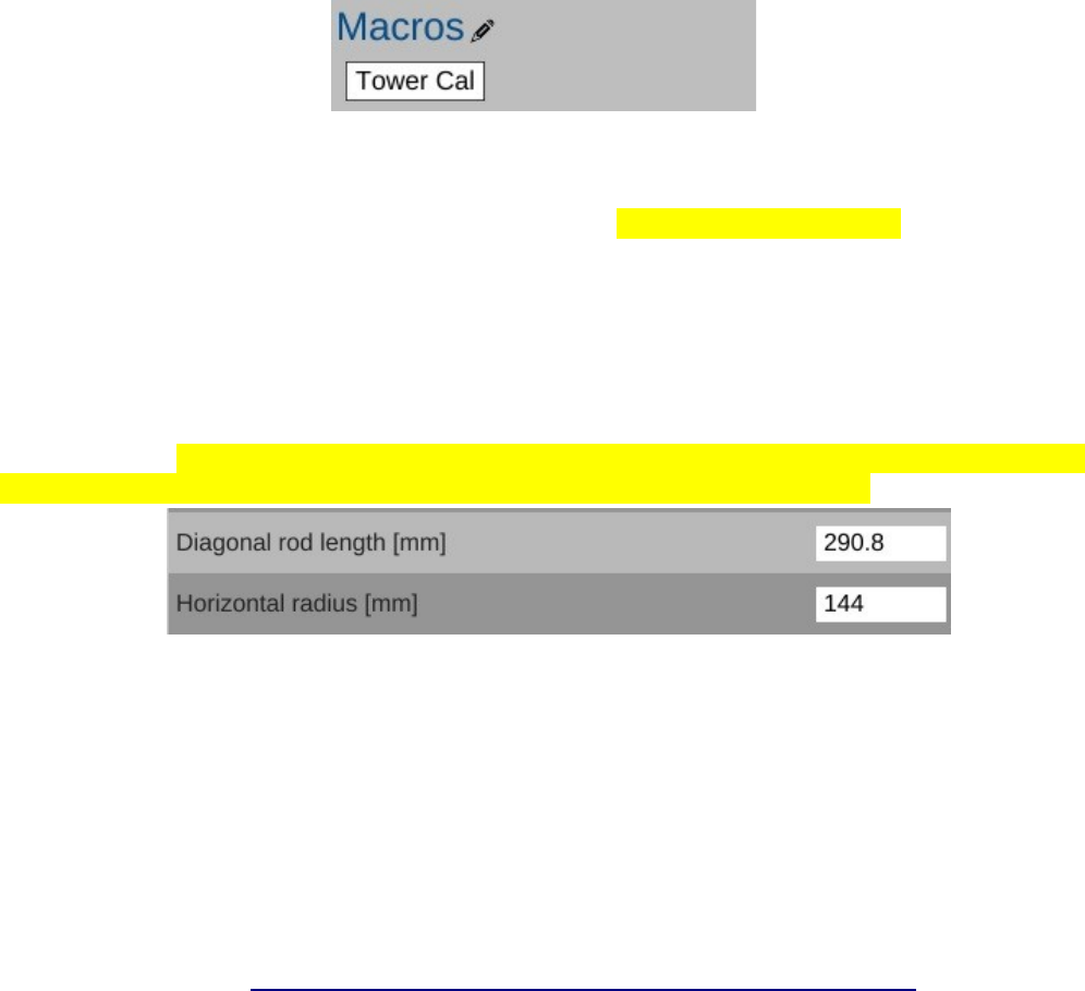
To make this process easier, we're going to create a macro within MatterControl.
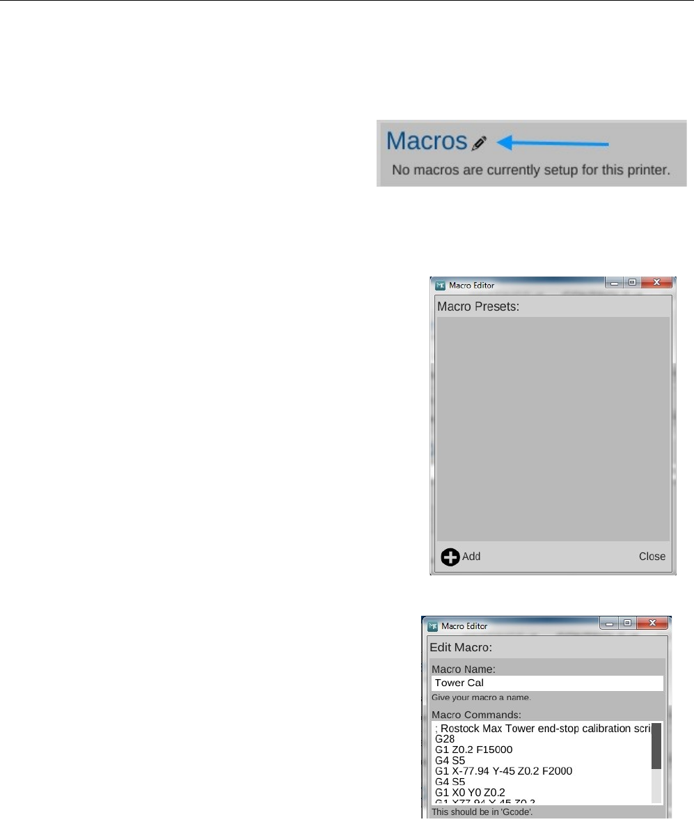
In order to create a new macro you'll need to
open the macro editor. Click on the little pencil icon
shown on the CONTROLS screen.
This will bring up the Macro Editor, as shown above. Click on the “ADD” button to create a
new macro.
You're going to name the new macro, “Tower Cal”.
In the Macro Commands box, you'll enter:
; Rostock Max Tower end-stop calibration script
G28
G1 Z0.2 F15000
G4 S5
G1 X-77.94 Y-45 Z0.2 F2000
G4 S5
G1 X0 Y0 Z0.2
G1 X77.94 Y-45 Z0.2
G4 S5
G1 X0 Y0 Z0.2
G1 Y90 Z0.2
G4 S5
G1 X0 Y0 Z0.2
If you're reading this as a PDF, you can easily copy &
paste the G-Code into the editor window. If you do this, it will
insert a blank like between each line of G-Code. You can
remove these blank lines.
Click the Save button to save the new macro.
2 – Installing MatterControl and Calibrating the Printer - 29
Fig. 2.4-1: Starting the Macro editor.
Fig. 2.4-2: Macro Editor.
Fig. 2.4-3: Calibration macro.
Rostock MAX v2 User's Guide
When you're done, click the Close button on the Macro Editor. The CONTROLS screen
should now have a macro display that looks like the figure below.
The macro will become a button you can click on. DO NOT CLICK IT YET.
In order to make the calibration as accurate as possible, you'll need to bring both the heated bed
and the hot end to operating temperature. Set the Extruder temperature to 190C and the Bed
temperature to 55C just as you did for setting the Z height.
Open the EEPROM editor and check the values shown below. If the Diagonal Rod Length
parameter isn't set to 290.8, please change it to that value. The starting position for the Horizontal
Radius is 144. [If you're working with an older v2 or v1 with the u-joint based arms, your Diagonal
Rod Length should be 269 and your starting Horizontal Radius should be 130.25]
Make sure you save your changes before you move on.
In order to help you calibrate the Rostock MAX v2, SeeMeCNC has created a neat video that
illustrates the entire process from beginning to end. In the video they're using the SeeMeCNC Orion
printer, but the technique is the same for the Rostock MAX v2. When you see reference in the video to
running the “TOWER.GCO” file, you'll instead click on the Tower Cal button that you just created the
macro for. They're the same thing, just executed differently.
https://www.youtube.com/watch?v=g3CqWxTcV38
When you click on the Tower Cal button, it will execute the script you just entered. The script
will move the nozzle to 0.2mm above the center of the build plate and pause for five seconds. It will
then move to the X tower, then the Y tower, then the Z tower, and finally will return to center.
You may notice an odd “arc” motion as the nozzle travels from point to point. This is a
mathematical phenomenon within the firmware and won't affect your calibration. You can safely
ignore it.
2 – Installing MatterControl and Calibrating the Printer - 30
Fig. 2.4-4: Available macros.
Fig. 2.4-5: Diagonal Rod & Horizontal Radius settings.
Rostock MAX v2 User's Guide
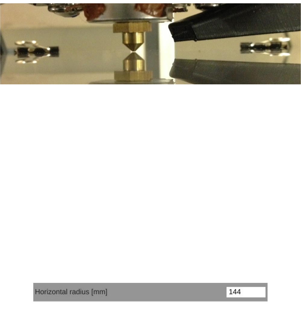
As the script runs, your focus should be on the nozzle where it pauses. You want to compare
the gap at the tower base to the gap at the center.
If the nozzle at the tower base is higher at the pause point in comparison to the center, you'll
want to turn the screw for that tower's end-stop counter-clockwise. Think “Turn Left to Lower”.
If the nozzle at the tower base is lower at the pause point in comparison to the center, you'll
want to turn the screw for that tower's end-stop clockwise. Think “Turn Right to Raise”.
Repeat this process for each of the three axes. You can adjust a single axis at a time, or you can
do two or all three. Doing all three at once may make you crazy unless you're a good juggler. Set the Z
height and Tower Cal macro each time you make a change to an end-stop screw.
When you're done, you need to re-set the Z height as it will have changed due to the calibration
process. Once you've re-set the Z height, run the Tower Cal macro again. Pay close attention to the
distance between the nozzle and the glass bed.
If from the center position, the nozzle goes down toward the glass at all three towers, you'll
need to change the Horizontal Radius value in the EEPROM. Open up the EEPROM table editor and
scroll down until you see the field marked below.
You'll want to raise this figure by 0.2. Run the Tower Cal macro after each change to check the
effectiveness of the change.
If from the center position the nozzle goes up from the glass at all three towers, you'll want to
lower the Horizontal Radius by 0.2. Run the Tower Cal macro after each change to check the
effectiveness of the change.
2 – Installing MatterControl and Calibrating the Printer - 31
Fig. 2.4-6: Nozzle at the center, 0.2mm above the glass.
Fig. 2-4.7: Horizontal Radius.
Rostock MAX v2 User's Guide
After doing this, you will see any changes where one tower may be higher than the other. If this
is the case, go back and re-adjust the end stop screws.
It can typically take anywhere from 5-10 iterations of the calibration process in order to get the
gap to remain the same at all three pause points compared to the center point. Once the gap is the same
at each tower compared to the center, the machine is calibrated and ready to print.
2.5 – Verifying Extruder Stepper Operation
Go to the CONTROLS pane in MatterControl and click the “PLA” button that's in the
“Extruder Temperature Override” box. The hot end needs to be heated in order to perform this next
test. The reason for this is that the firmware is designed such that it will not permit extrusion if the hot
end is cold.
Once the hot end has reached the target temp (190C in this case), click the “E+” button to
extrude some filament.
Watch the knob on the extruder when you click that button. You
should see the knob slowly turn counter-clockwise. If it's turning
clockwise, you'll have to make a change in the firmware. It's a very
simple change and you shouldn't have any problem at all doing it.
If you've got backwards-running stepper motor, you'll need to
open the Arduino IDE and make a single change in Configuration.h.
Look for the following line:
#define EXT0_INVERSE true
You'll find it on or close to line #195 in the file. Whatever the value is set to, invert it. If it's
true, change it to “false”. If it's false, change it to “true”. Save your changes and then upload the
firmware to the RAMBo. Make sure you've got MatterControl disconnected or the Arduino IDE won't
be able to talk to the board.
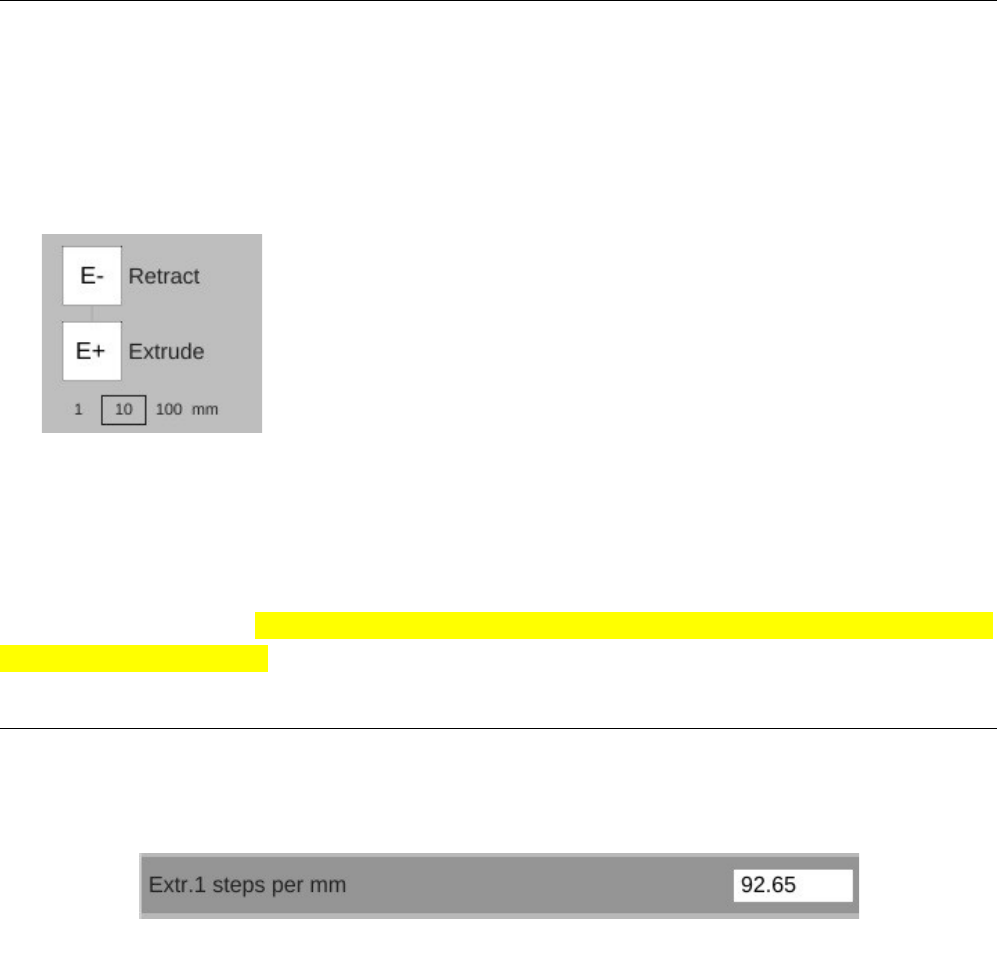
2.6 – Extruder Calibration
The last task you'll need to perform before you can load plastic in to the machine is to correctly
set the steps per mm (“E-Steps”) for the extruder. Open up the EEPROM configuration editor and look
for the label shown below. Your default starting point should be 92.65.
2 – Installing MatterControl and Calibrating the Printer - 32
Fig. 2.6-1: Extruder steps per mm.
Fig. 2.5-1: Extrude Filament
control.

Rostock MAX v2 User's Guide
This value dictates the number of steps that the stepper motor must rotate in order to feed 1mm
worth of filament to the hot end. The figure supplied will get your e-steps very close to ideal, but extra
fine tuning should be done. I highly recommend that you check out the “E Steps Fine Tuning” section
of Triffid_Hunter's excellent calibration guide. It can be found here:
http://reprap.org/wiki/Triffid_Hunter%27s_Calibration_Guide
The other portions of his calibration guide doesn't really apply to the Rostock MAX v2, so it's
not necessary to read unless you're simply curious.
WARNING: At no time should you allow your hot end temperature
to exceed 245C! The PEEK section of the stock hot end will melt
at 247C, requiring its replacement!
2 – Installing MatterControl and Calibrating the Printer - 33
Rostock MAX v2 User's Guide
3 – First Print: PEEK Fan Shroud
For your first (and second!) prints, you're going to need to have ABS filament handy. This is
because the PEEK and Layer fan shrouds can be exposed to temperatures that would turn PLA shrouds
into a gooey mess. You're also going to need the 25x25x10mm PEEK fan itself.
3.1 – Configuring the Slicer
The process of converting a 3D model into something you can print is called “slicing”. The
software used for this process is typically called a “slicer”. Essentially a slicer cuts up your 3D model
into hundreds (sometimes thousands!) of tiny slices that are then converted into code that the printer
controller can understand. MatterControl contains three slicing “engines”: Slic3r, CuraEngine and
MatterSlice. I'm only going to cover the MatterSlice engine configuration for right now.
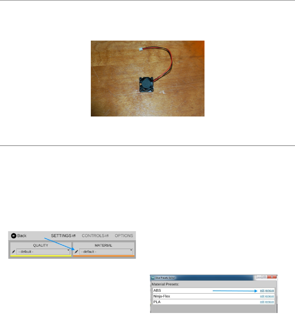
Before you can begin your first print, you're going to customize your first material profile!
Click on the SETTINGS button. This will bring up the materials pane.
Click on the Toolbox icon pointed to by the arrow.
This will open a list of your currently configured
materials.
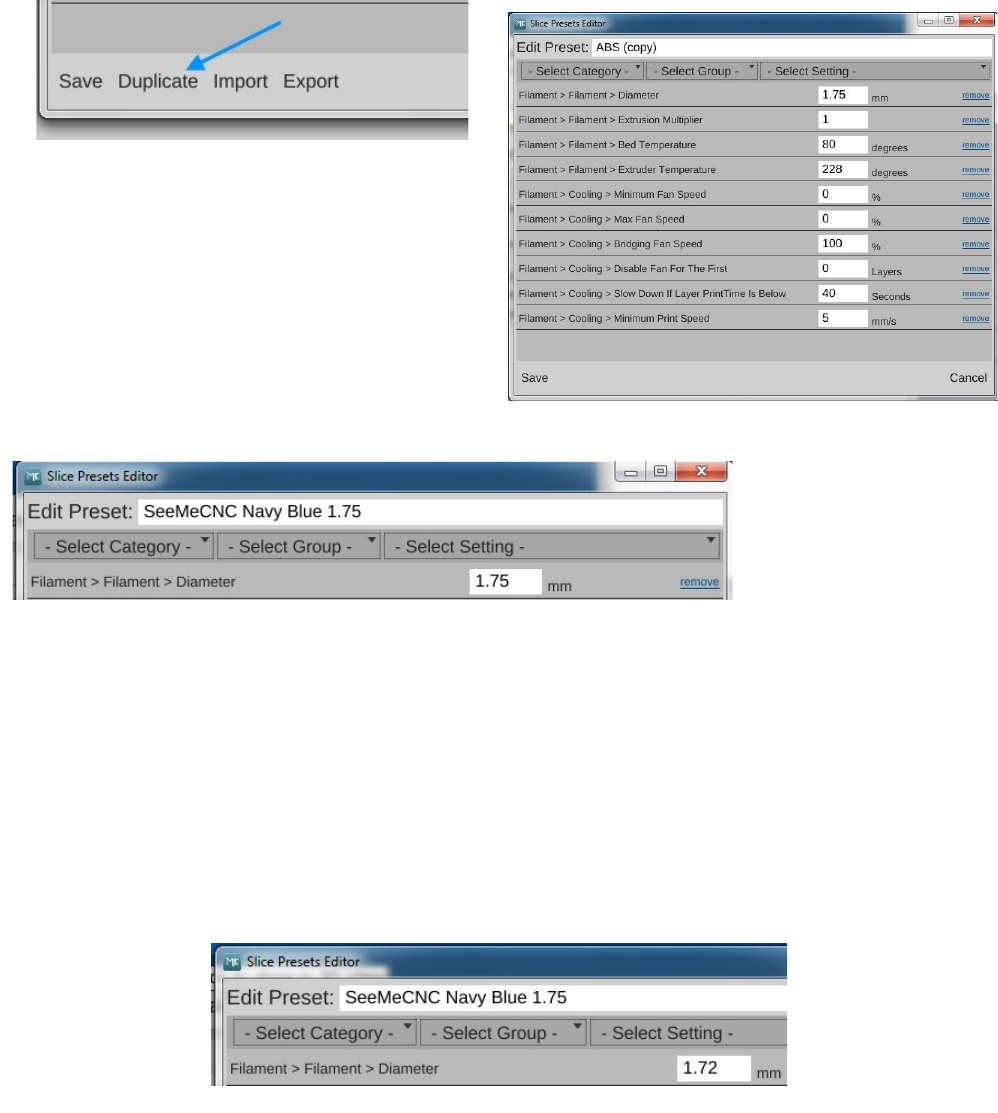
Click the edit field for the ABS
configuration. When the Presets Editor window
appears, click on “Duplicate”. This will create a
new preset called “ABS (copy)”.
3 – First Print: PEEK Fan Shroud - 34
PEEK Cooling Fan.
Fig. 3.1-1: Materials pane.
Fig. 3.1-2: Material presets.
Rostock MAX v2 User's Guide
Click in the box that holds the name of the
profile and change it to something that's descriptive
of the material. Since I'm using a navy blue ABS
filament I got from SeeMeCNC, I'm naming this
preset “SeeMeCNC Navy Blue ABS 1.75”
Now before you can save your new preset, you need to get a good idea of the actual diameter of
your filament. This is important to know in order to get good print results.
I want you to cut off about 2 meters of filament from the spool you're going to use to print the
fan shroud. Using your digital caliper, take 5 measurements along the length and record each one.
When you're done, calculate the average filament diameter and put that figure into the Diameter size
field. It may be less than 1.75mm, but shouldn't be any more than 1.8mm. If you have any
measurements of 1.8mm or greater on your filament, it may bind in the hot end. In my case, the
filament average was 1.72, so that's what I entered.
After you've updated the filament diameter, click Save to commit your changes. When the
editor window is dismissed, you'll see your new material preset in the list!
3 – First Print: PEEK Fan Shroud - 35
Fig. 3.1-3: Duplicating a preset.
Fig. 3.1-4: Copied preset.
Fig. 3.1-5: A new material preset!
Fig. 3.1-6: Updated filament diameter.
Rostock MAX v2 User's Guide
Click Close to dismiss the Presets Editor and we'll move on to the next step, printing your first
part!
3.2 – Printing The PEEK Fan Shroud
If you downloaded the MatterControl presets file, you can skip downloading the file from
Repables.
Go here: http://repables.com/r/620/ and click the “Download” link. When the download is
finished, unzip the file. This is the STL file that MatterSlice will process and turn into your first print!
When you've got the file downloaded, you can load it into MatterControl by clicking on the
“Add” button and selecting the STL file you want. Note that if your Queue shows the example parts
from MatterControl, click the Remove button to get rid of them.
Once the open file dialog opens, navigate to where
you unpacked the file.
Now that you've got the file loaded, we need to load filament into the printer!
3 – First Print: PEEK Fan Shroud - 36
Fig. 3.1-7: New material preset!
Fig. 3.2-1: Loading an STL file.
Fig. 3.2-2: Part loaded!
Rostock MAX v2 User's Guide
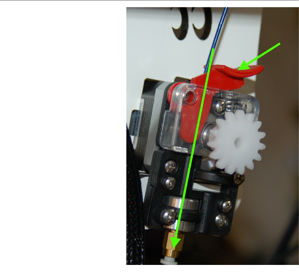
3.3 – Loading Filament
It's extremely simple to load
filament into the EZStruder. Just place
your index finger on the top of the extruder
and your thumb on the tension lever
(marked by the arrow below). Press the
tension lever down and feed the filament
by hand along the path marked by the green
arrow. There is a small opening behind the
tension lever that the filament will enter
into the extruder through.
3 – First Print: PEEK Fan Shroud - 37
Fig. 3.3-1: Loading filament.
Rostock MAX v2 User's Guide
Continue to manually feed the filament until it passes through the other push-fit connector on
the hot end.
Now you'll need to heat the hot end in order to prime it with filament. Once the hot end reaches
the target temperature, I want you to start using the manual Extrusion button to feed filament into the
hot end.
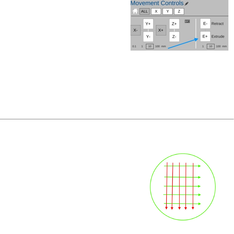
In the figure to the right, you'll see the control
panel for the extruder. In order to safely feed the hot end,
make sure that you've selected “10” in the settings below
the E+ button. Click the E+ button to begin feeding
filament through the hot end. You may have to click the
button a number of times to get filament coming out of
the hot end, but you'll want to wait for the extruder to
stop moving before you click it again.
Once it does begin to feed, go ahead and click the E+ button a few more times just to get the
extruder all nice and primed.
I recommend that you extrude 20-30mm of filament each time you start up the printer for the
day. This ensures that the hot end is primed and you have no jamming issues.
3.4 – Preparing the Heated Bed
ABS won't stick to bare glass. In order to get the ABS to stick, you're going to need to apply
two thin layers of glue to the bed. Remember back in the “need to have” list, I listed the Elmer's
“Disappearing Purple” glue stick? This is where you're going to use it.
You'll want to apply two perpendicular layers of
glue on to the heated bed. Follow the simple pattern
shown on the right. The green lines represent the first
layer and the red lines represent the second. The idea is to
lay down a thin, even layer with no spaces between each
“lane” of glue. Let the base layer completely dry before
applying the second layer. Let THAT layer dry before
starting a print.
3 – First Print: PEEK Fan Shroud - 38
Fig. 3.4-1: Glue application.
Fig. 3.3-2: Extruder control.
Rostock MAX v2 User's Guide
3.5 – Printing the PEEK Fan Shroud
Check on the Slice Settings pane to make sure that you've got “MatterSlice” chosen for the
slice engine, “STANDARD” chosen for Quality, and “ABS” chosen for Material. Make sure that the
filament you have loaded in your printer IS ABS! Running PLA at ABS temperatures without the
PEEK fan installed will cause the hot end to jam!
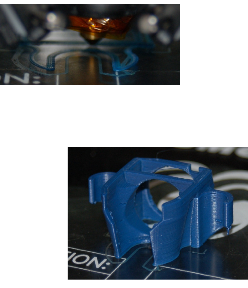
Now that you've gotten everything loaded and prepped, starting the print is as simple as clicking
on the “Print” button.
When you click the Print button, the hot end and the heated bed will begin to heat. The hot end
will reach its target temperature first because it has much less mass to heat than the heated bed. The
heated bed can take up to 10 minutes or so to reach its target temperature.
Once both the bed and hot end are hot, the printer will home and the print job will begin!
3 – First Print: PEEK Fan Shroud - 39
Fig. 3.5-2: Starting the print job.
Fig. 3.5-3: Heating up!
Fig. 3.5-1: Correct slice settings.
Rostock MAX v2 User's Guide
Right before the printer begins to print, the RAMBo controller will “chirp” the LCD speaker
and you'll see a text warning on the LCD controller to keep your hands away. There will be a short
delay after this and the print job will begin!
The print will take roughly an hour to complete. When the job finishes, MatterControl will
issue a bell sound and the machine will home itself. (It's actually more of a “Hey! YOUR TOAST IS
DONE!” dinging sound, but you get the idea...)
To the left is a photo of the PEEK
fan shroud I printed. It's got a few defects,
mostly due to a slight amount of over-
extrusion. As you get more familiar with
the Rostock MAX v2 and 3D printing in
general, you'll learn how to fix issues like
this to get excellent prints!
After the print job is complete, the
power to the hot end and the heated bed
will be turned off. When the heated bed
reaches around 40C, you'll probably hear a
cracking sound as the part separates from
the bed.
Even if you don't hear this sound, the part should come free of the bed pretty easily after the bed
has had a chance to cool.
3 – First Print: PEEK Fan Shroud - 40
Fig. 3.5-4: The first layer.
Fig. 3.5-5: Completed PEEK Fan Shroud.
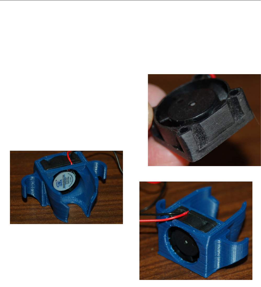
Rostock MAX v2 User's Guide
3.6 – Installing the PEEK Fan and Shroud
Before you can install the PEEK fan shroud, you're going to have to wait for the hot end to cool
to room temperature. You don't want to burn yourself while installing the shroud.
While you're waiting for the hot end to cool down, go ahead and install the 25x25x10mm fan
into the shroud. I'll warn you right now – it's going to be a VERY tight fit. The issue is that the fan is
manufactured to a bit of a larger size than it's nominal 25x25x10 size indicates. One of the issues this
presents is that the thin walls of the fan frame can deform and prevent the fan blades from moving.
This can be solved by sanding just a tiny amount from the sides of the fan as shown below.
It looks like I removed a lot of material, but it's
really only about 0.25mm.
Take a little off at a time and check for fit each
time. You'll eventually reach a point where you can blow
on the fan blades and they'll spin without striking the
inside wall of the fan frame itself. Take care not to
remove too much at one time – you don't want the fan to
be loose in the shroud.
Make sure you've got the fan oriented exactly
as shown. You want the label of the fan facing the
space where the hot end will be. The power wires for
the fan should rest in the notch provided.
You also want to make sure that the fan is fully
seated. The fan shroud fits between the effector
platform and the hot end mount.
3 – First Print: PEEK Fan Shroud - 41
Fig. 3.6-1: Thinning down the fan.
Fig. 3.6-2: Fan installed, inside view.
Fig. 3.6-3:Fan installed, outside view.
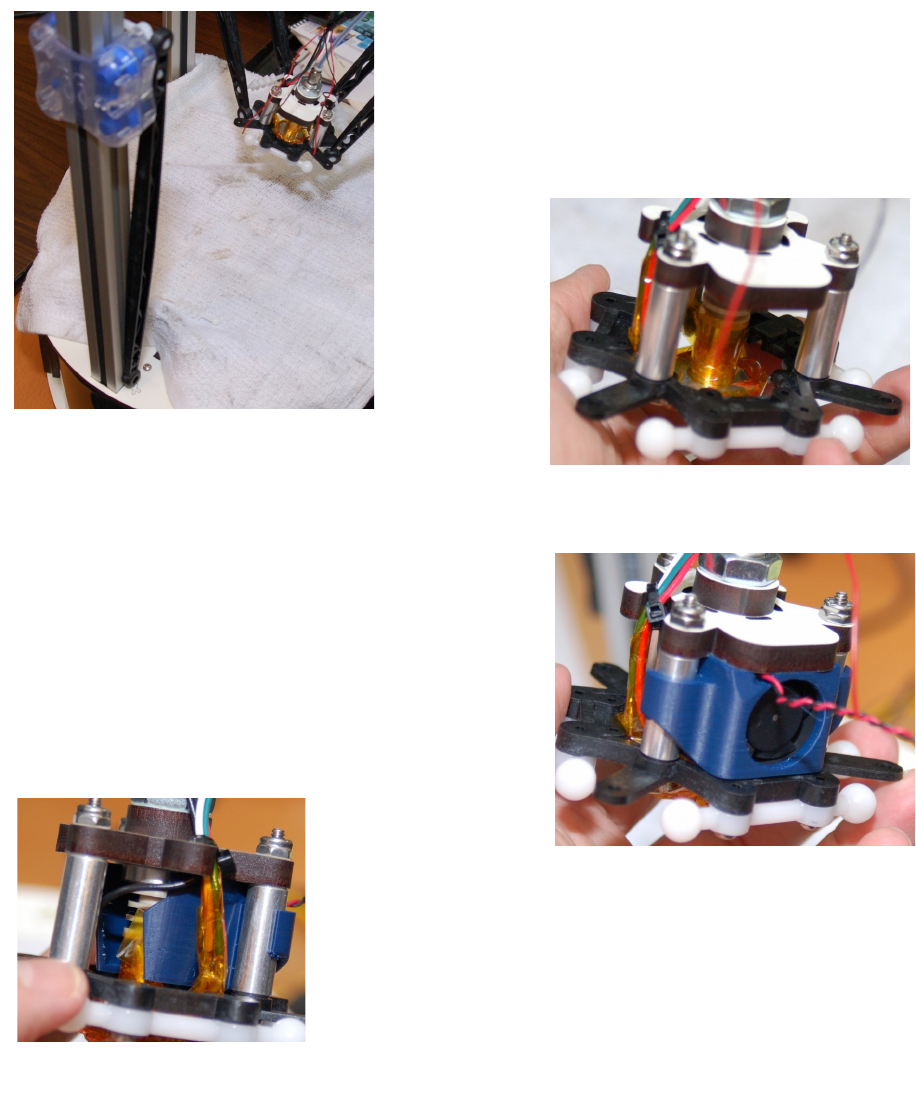
Rostock MAX v2 User's Guide
In order to install the fan, you'll have to remove the arms from the effector platform. Release
the arms at the effector end and put the ends to either side of the tower as shown. By leaving the
carriage end spring clip in, the arm ends will grip the extrusion lightly. This helps when you're re-
assembling things. I would also recommend you lay some cloth on the heated bed to protect it.
Once you've got the arms removed from the effector
platform, you can slide the fan into the “back” of the hot end
assembly. The location is shown below. You may need to
rotate the hot end so that the sides of the fan shroud can easily
pass between the hot end's power wires and the hot end itself.
You do not want to trap a power wire between
the fan shroud and the hot end, so make sure those wires clear.
You should be able to insert the fan & shroud as
shown on the right. If it's a bit too tight to fit, loosen the
three screws that hold the hot end to the effector
platform. When the fan shroud is fully inserted, the
“arms” of the shroud should be in full contact with the
aluminum spacer on either side. Don't forget to re-
tighten the screws once you've go the fan installed.
Now you can re-mount the arms on to the effector platform. As
you re-install each arm pair, move its carriage down to the bottom.
This will have the hot end in the inverted position when you're done,
making the wiring job a bit easier to accomplish.
3 – First Print: PEEK Fan Shroud - 42
Fig. 3.6-4: Removing the arms.
Fig. 3.6-5: Fan location.
Fig. 3.6-6: Shroud installed.
Fig. 3.6-7: Side view of the
shroud.
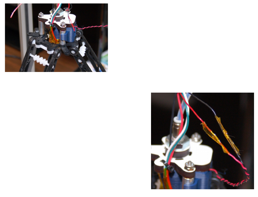
Rostock MAX v2 User's Guide
Once you have all the arms on, you can wire up the fan.
The PEEK fan wires are the pair you knotted. Un-knot and
strip about 1/2” of insulation. Cut off the connector on the
25mm fan (if present) and strip those as well. I recommend
against shortening the wires – you may want to install a
connector on them that will allow you to remove the hot end
or fan without cutting wires. Splice the wires as you did with
the extruder motor wiring and cover the joint with Kapton
tape as shown.
Move the arms one at a time back to their
normal position. Note that you don't want to move
the carriages quickly. The stepper motors can
generate power and damage the RAMBo if they're
moved too quickly.
The PEEK fan shroud is “virtually” linked to
the hot end power. You should be able to see the fan
running as soon as you start heating the hot end.
Do that now to make sure the fan operates.
When you run a print job, the PEEK fan will
continue to run even after power has been removed
from the hot end. It will continue to run until the hot end temperature falls below 50C.
3 – First Print: PEEK Fan Shroud - 43
Fig. 3.6-8: Ready to wire!
Fig. 3.6-9: All done.
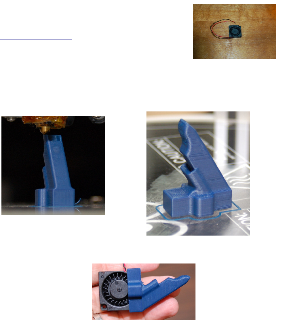
Rostock MAX v2 User's Guide
4 – Second Print: Layer Fan Shroud
If you plan on printing in PLA or other materials that can
benefit from a cooling fan (NOT ABS!), you'll want to print the layer
fan shroud. The layer fan model can be downloaded from Repables,
http://repables.com/r/621/.
It's specifically designed to mount on the effector platform
and uses the included 30mm squirrel cage fan.
Download, extract and load the layer fan model into MatterControl, just as you did for the
PEEK fan. The printing parameters are the same. Make sure you've got the same slicing configuration
you used as last time and hit the Print button!
When you're able to remove the part from
the print bed, insert the tiny squirrel cage fan into the shroud as shown below.
4 – Second Print: Layer Fan Shroud - 44
The Layer Fan.
Fig. 4.1-1: Almost done!
Fig. 4.1-2: Completed fan duct.
Fig. 4.1-3: Fan installed in the duct.
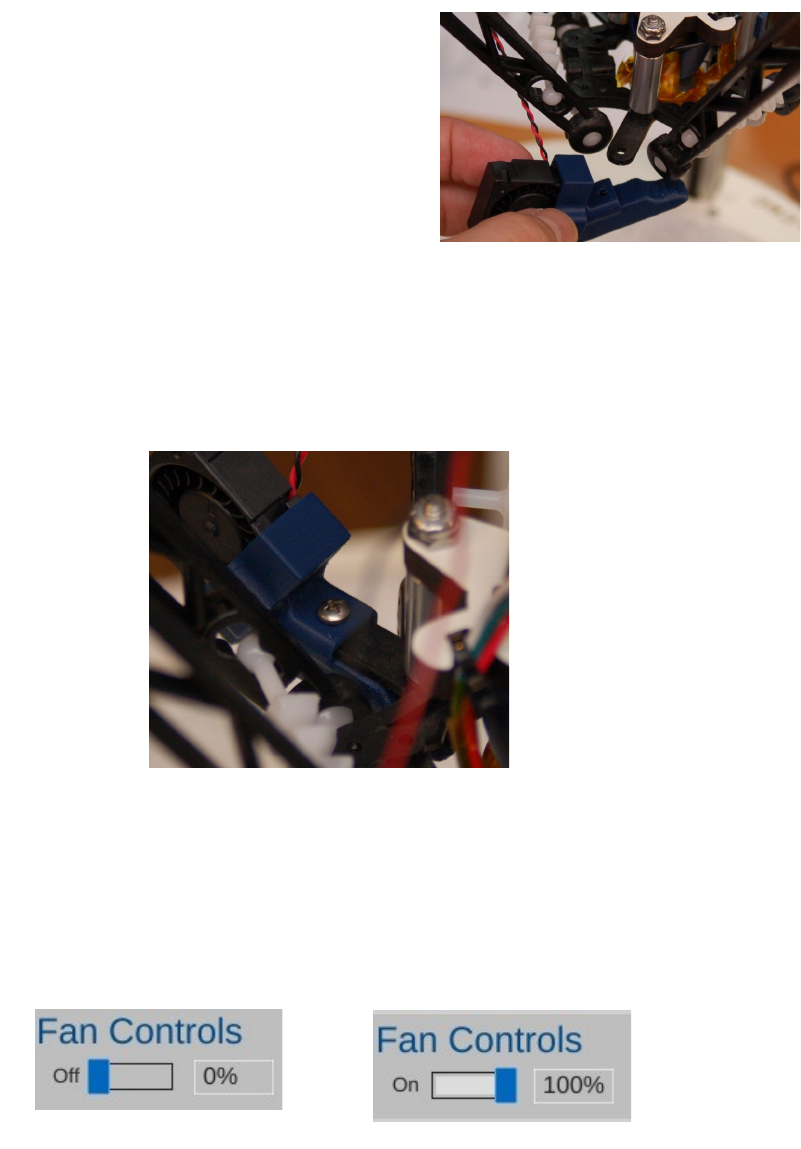
Rostock MAX v2 User's Guide
The effector platform provides three mounting locations for the layer fan. Yes, you can install
three of them if you really want. :)
With the machine powered off, slide each Cheapskate
down to the base of the tower so that your hot end is at the top
of a pyramid formed by the three arms. Lay a washcloth or
towel on your heated bed to protect it while you're working on
the hot end.
Choose a mounting point and test fit the shroud. It
should be a snug fit, but if it won't fit at all, you may need to
clean out the tab pocket with a razor knife.
Leave the fan sitting at the position you chose and solder the fan leads to the last remaining
26ga wire pair coming out of the mesh loom. Cover the solder joints with Kapton tape and use a #4
machine screw to fix the fan shroud into place.
Before you return the hot end to its operating position, turn on the printer and connect
MatterControl to it. You're going to test the fan to make sure it works and the fan blades don't rub on
the shroud. DO NOT HOME THE MACHINE WITH THE ARMS INVERTED!
Click on the Controls pane and then set the fan speed to 100% by clicking on “switch” indicted
by the arrow in the image below. Once you do this the fan should start at it's default speed of 100%.
4 – Second Print: Layer Fan Shroud - 45
Fig. 4.1-6:Starting the layer fan. Fig. 4.1-7:Fan running.
Fig. 4.1-4: Mounting tab.
Fig. 4.1-5: Done!
Rostock MAX v2 User's Guide
The fan should start running at full speed. Make sure that it's spinning the correct direction by
holding your hand under the fan shroud to check for moving air. If it's not blowing air, you've likely
connected the wires backwards. :) Correct it and try again.
To turn the fan off, just click in the fan speed box and enter “0” followed by ENTER or click on
the “Set” button.
With the installation of the layer fan, your Rostock MAX v2 is totally complete and you may
now...
4 – Second Print: Layer Fan Shroud - 46

Rostock MAX v2 User's Guide
5 – Matter Control Basics: Slicing
MatterControl is a very complete 3D printing package and it's got a LOT of options. Some
people can find this intimidating, but I assure you – there's nothing to be worried about!
MatterControl is an integrated host application. This means that it provides everything needed
to control the Rostock MAX and to prepare models for printing. The task of preparing a model for
printing is called “slicing”. It's a very descriptive term for what is actually happening. In order to print
a 3D model, it needs to be converted from a solid object into a series of very thin layers that are in turn
converted into G-Code (more on this later). For example, if your print layer height is 0.2mm, the
slicing tool is going to “slice” your model into a number of layers – basically the model height divided
by 0.2mm. For a tall part, this can mean a LOT of layers!
MatterControl provides three slicers for your use. MatterSlice, CuraEngine, and Slic3r. This
guide will only cover the specifics of MatterSlice, but don't let that stop you from experimenting with
and using the other slicers! I'll show you how to change the slicing engine later on in this guide.
The final task of the slicer is to translate the sliced layers of model into something called G-
Code. G-Code is a simple control language that's used to position the print head and tell the extruder
how much plastic to deliver and at what rate. Going into the details of G-Code is beyond the scope of
this guide, but if you'd like to learn more you can check out the following resources:
http://en.wikipidia.org/wiki/G-code and http://reprap.org/wiki/G-code.
For the most part, you'll never directly interact with G-Code, but it's nice to know what's going
on behind the curtain!
5 – Matter Control Basics: Slicing - 47
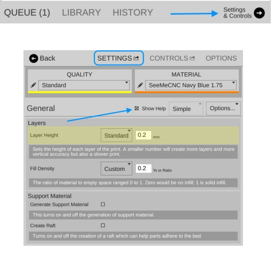
Rostock MAX v2 User's Guide
I want you to click on the Settings & Controls button to bring up the Settings, Controls, and
Options pane.
Click on the SETTINGS link to make sure your display follows (by and large) what you see
below.
The first thing I want you to do is click on the Show Help check box that's highlighted by the
arrow in the image above. This will turn on verbose descriptions of each one of the parameters
available in the Settings page.
I'm going to only cover the “Basic” configuration settings for right now. There's a LOT that
goes on to configuring your slicer and the Simple configuration setting allows many of those to be
hidden until you're more comfortable with how your printer works.
5 – Matter Control Basics: Slicing - 48
Fig. 5.1-1: Menu Bar.
Fig. 5.1-2: Settings Pane.
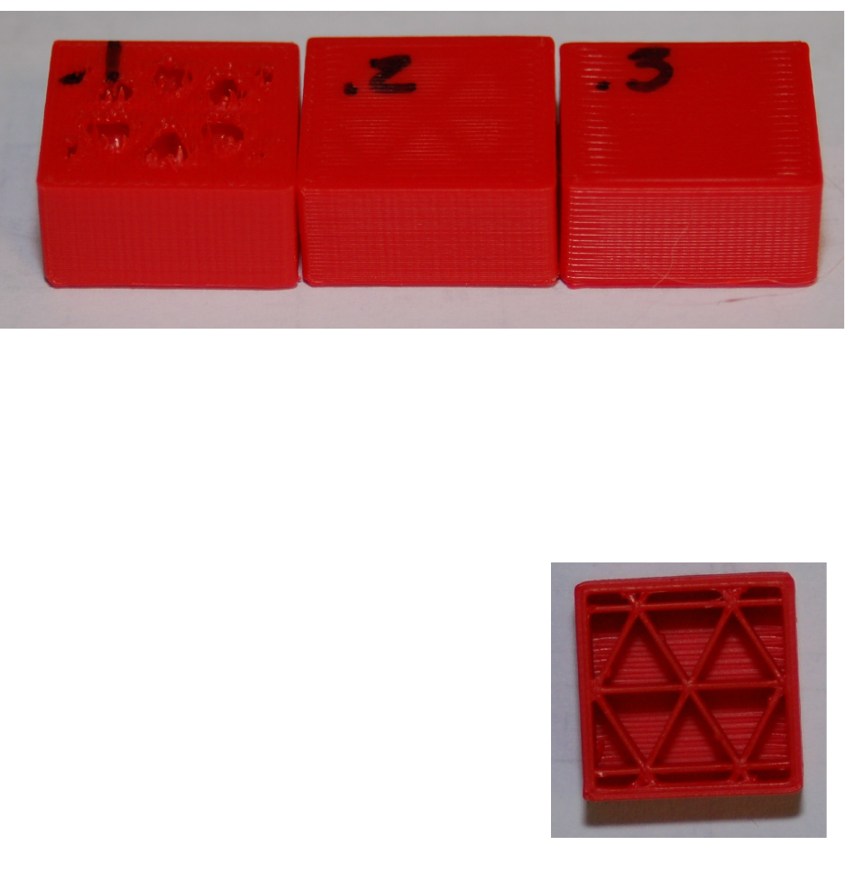
Rostock MAX v2 User's Guide
Layer Height – This parameter tells the slicing engine how thin to make the layers when it
slices up the model as I described earlier. A good default layer height is 0.2 or 0.25mm. The lowest
practical layer height with a 0.5mm nozzle is 0.1mm. You can go lower than that, but it requires a
smaller nozzle diameter. You can also got a lot thicker, but that requires a larger nozzle. If you change
the Quality from Standard to Coarse or Fine, you'll notice how the layer height changes.
Here's what the Coarse, Standard, and Fine layer heights look like when printing the little test
cube in ABS plastic.
Starting from left to right, the layer heights are 0.1mm, 0.2mm and 0.3mm. You'll notice that
the top layer on the 0.1mm print is kind of ratty and torn up. This is because the number of top layers
is set to 3. This is perfectly ok with thicker layer heights, but it should have been set to at least 5 for the
0.1mm layer height that the Fine setting uses. You'll learn how to tweak that in a little bit.
You can see how the smoothness of the sides decrease as the layer thickness increases. If you
want to print something really quick, you could go up to a 0.35mm layer height. I wouldn't recommend
anything over 0.40mm if you're using a 0.5mm nozzle however.
Fill Density – This parameter controls how solid your
printed part is. The number is a percentage, from 0 (totally
hollow) to 1 (totally solid). The default fill density (also known as
“infill”) is 0.2 or 20%. The image below shows what that looks
like inside our little test cube.
You can tweak the infill to get a more robust or a lighter
part. For most prints, 20% is a good infill value.
Later on I'll show you how to change to a different infill
pattern. The one shown on the right is the Triangle pattern.
5 – Matter Control Basics: Slicing - 49
Fig. 5.1-3: Layer height examples.
Fig. 5.1-4: 20% infill example.
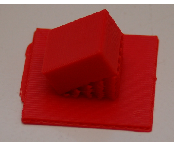
Rostock MAX v2 User's Guide
Support Material – Support material is used when the part you're printing has free-standing
features (like the chin on a bust) or another feature that requires it to be physically supported during the
printing process. When you check the Support Material box, the slicer will automatically design
support for the part that's currently (or will be) loaded.
Create Raft – A raft is essentially what it says, a “raft” of material that your part will print on
top of. Rafts are most often used when printing a part that is having bed adhesion problems due to its
geometry. For example, if you're printing a part that sits on small feet, a raft would come in handy if
the initial layers of the feet don't stick very well.
In the image below, you'll see an example of both support material and a raft.
I took the little test cube and through a little manipulation, printed it tilted at 30 degrees. I took
this opportunity to also demonstrate what a raft looks like. This one is exaggerated in its size, but gives
a great example of what a typical raft will look like.
5 – Matter Control Basics: Slicing - 50
Fig. 5.1-5: Support material and raft.
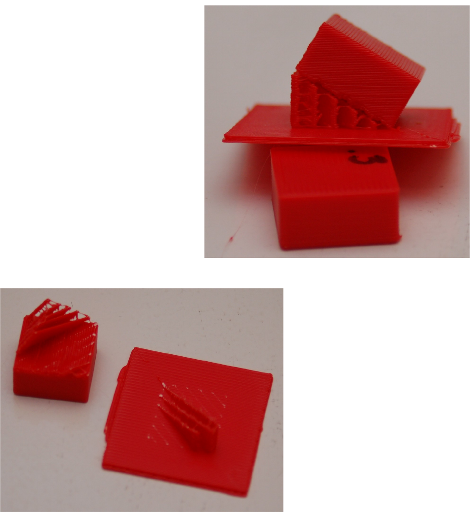
Rostock MAX v2 User's Guide
The image to the right should give
you a pretty good idea of what the part
looks like from the side. You can easily
see the support material as well as the
layer lines that will be at a 30 degree angle
when the little cube is laid flat.
Support material is generated in
such a way that there is just enough of it
there to handle the actual print layer that it
will be supporting. In my example, the
support material has a 2.5mm spacing
between the walls of support material and
it uses an infill angle of 45 degrees.
The printed part will usually separate from the support material fairly easily – however, some
material will be left behind if you're using a raft. Cleaning up the left over support material is a simple
and straightforward task.
5 – Matter Control Basics: Slicing - 51
Fig. 5.1-6: Support & Raft.
Fig. 5.1-7: Part separated from the raft.
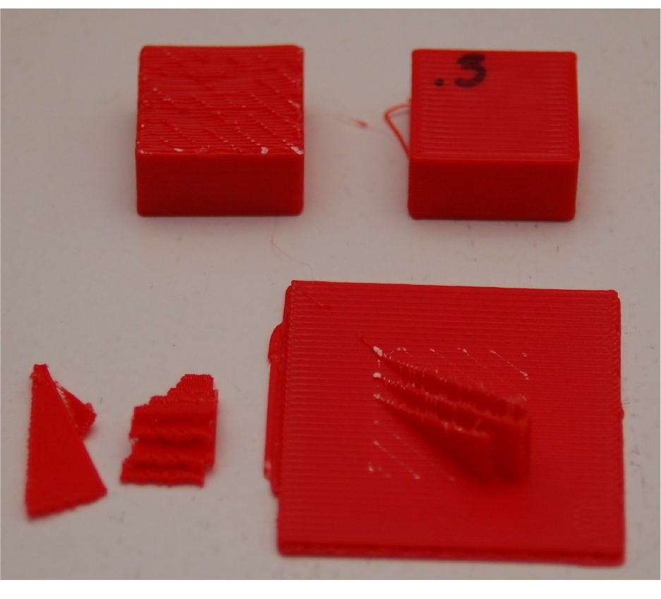
Rostock MAX v2 User's Guide
Here's what you end up with after removing the support material from your part. As you can
see, there's still a little clean up to to be done to the printed cube (on the left). A quick hit with some
220 grit sandpaper will knock the rough edges of the support material down.
That's pretty much all there is to the Simple settings level. Next, let's dig into the Intermediate
setting!
5 – Matter Control Basics: Slicing - 52
Fig. 5.1-8: Part cleanup.
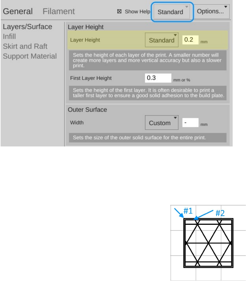
Rostock MAX v2 User's Guide
Click on the Simple setting drop down and pick Standard. Your MatterControl settings screen
should change to something resembling the image below.
Quite a number of new configuration options are accessible under the Standard settings level.
The first set of options we'll tackle live under the Print heading.
Layers/Surface – This setting page allows you tweak the layer height just as before when in
Basic mode, but now adds the First Layer Height and Outer Surface settings.
The First Layer Height setting allows you to specify how thick you want the first layer of the
print to be. Bed adhesion depends on a good first layer!
The Outer Surface setting is often called “shells” because it controls
how thick the “skin” of your printed object is going to be. The Standard
setting will set the outer surface thickness to 0.6mm. I would
recommend you choose the Full setting. This will give you a wall
thickness of 1mm. Note that you can also specify how thick you want
the wall by choosing the Custom setting and then enter the value (in
mm) that you want the wall thickness to be.
5 – Matter Control Basics: Slicing - 53
Fig. 5.1-9: Intermediate Settings.
Fig. 5.1-10:Perimeters in
Layer View.
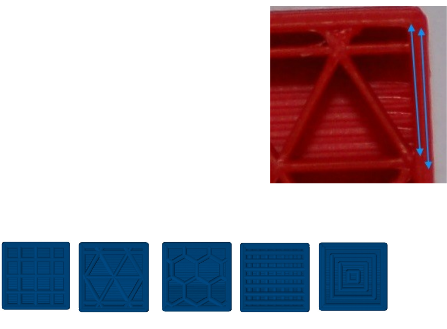
Rostock MAX v2 User's Guide
In Fig. 5.1-10 is an example of what the Standard setting looks like. When the cube is being
printed, the #2 perimeter is printed first and then the #1 perimeter. (The order is configurable.)
On the right, you can see what those perimeters
actually look like on the cube we printed earlier.
Infill - The Standard level adds Infill Type in
addition to the Fill Density figure we covered before. The
infill types available are Grid, Triangles, Hexagon, Lines, and Concentric. Examples are shown
below.
The Lines infill pattern differ from the others in that the line orientation is alternated every
other layer. All the examples show a 20% infill density.
You're probably wondering which infill pattern is “best”. I wish I could go into that, but I've
been unable to locate any studies that cover the topic in any depth. If I were asked to provide a
recommendation for a good structural pattern I would probably pick the Triangles option. It offers a
good internal structure for most infill densities that I've used it with.
Skirt and Raft – This is a new option that appears with the Standard and Advanced setting
levels. The Skirt option is used one of two ways. First, it can be used to “prime” the hot end with
filament before the actual part itself begins to print. You may notice that your hot end may “drool”
filament while the bed is heating up and the hot end has already reached temperature. This is perfectly
normal. However, without some kind of priming action, early features of your part may not print
properly. The Skirt solves this.
5 – Matter Control Basics: Slicing - 54
Triangles Lines Concentric
Grid Hexagon
Fig. 5.1-11:Perimeters as printed.

Rostock MAX v2 User's Guide
Secondly, the Skirt can become a Brim if the Distance from Object setting is set to zero.
What this does is make sure that the skirt is physically connects to the part, becoming a brim. This can
be handy when you're printing a small part and you're having bed adhesion issues and you don't want to
have to use a raft. Later on in the Advanced settings section, you'll see more options on how you can
tweak the Skirt and Raft settings.
Support Material – With the Standard and Advanced setting levels, you get more control
over how the support material for your part is generated.
The new option here is called Support Type and allows you to choose a LINES or GRID
pattern for the support material. When I printed the support example, I used the LINES mode as that is
the default for the Basic settings mode. Looking down on it from above, this is what the LINES
support material pattern looked like for that print.
This shows the second layer of the print. The lines will continue to stack upon
one another for the entirety of the support structure.
The GRID pattern (below) uses the same spacing as the LINES option, but is designed to
provide more support where it may help to provide a better end result.
The next new category exposed by the Standard setting is called Filament. It provides
Filament and Cooling categories. The Filament category includes the following options:
Diameter – This is the diameter of the filament you're using. The more accurate this figure is,
the better the quality of your prints. This is because the slicer uses the filament diameter to help
calculate the optimum flow rate for the extruder during the print.
In order to get an accurate filament diameter, spool off a meter or so of filament and check it in
10 spots along the length of the material. Record the measurements using a digital micrometer and
average the results. That average should go into the Diameter field.
Extruder Temperature – This figure determines the target temperature of the hot end for the
material you're printing with. A typical heat range for ABS is 220 to 240C and 190 to 220C for PLA.
Other materials will have their own recommended temperature ranges. NEVER, EVER, EXCEED
245C WITH THE STOCK HOT END!
5 – Matter Control Basics: Slicing - 55
Rostock MAX v2 User's Guide
The reason for this is because of how the stock hot end is designed. It uses a PEEK section (a
high-temperature plastic) as the “cold end” of the hot end. This material will begin to fail at 247C. If
you need to print with a high-temperature filament such as Nylon, it's highly recommended that you
purchase an all-metal hot end.
Extruder Wipe Temperature – This setting determines what temperature the hot end should
be before performing a “wipe” operation. Leave this setting at its default of 0.
Bed Temperature – Like the Extruder Temperature the bed temperature is material-
dependent. For ABS, a typical heated bed temperature range is between 80 and 100C. For PLA the
range is typically 55 to 65C.
Bed Remove Part Temperature – This is the temperature the bed should be before removing
the part from the heated bed. Leave this setting at its default of zero.
Retraction – Length on Move – This sets the distance the extruder should “retract” the
filament out of the hot end. This is used when the nozzle is moving from place to place, but not
printing. Retracts are used to prevent the nozzle from “drooling” on the print while it's rapidly
traveling from one position to the next during a print job.
Retraction – Speed - This sets how fast the extruder motor retracts the filament out of the print
head.
Retraction – Z Lift – This setting will cause the nozzle to lift a small amount before
performing a non-printing move.
Retraction – Wipe Before Retract – This will cause the printer to try to wipe the nozzle before
it performs a rapid move.
The Cooling category will allow you to specify the minimum and maximum fan speed that will
be used if you've got cooling enabled.
5 – Matter Control Basics: Slicing - 56
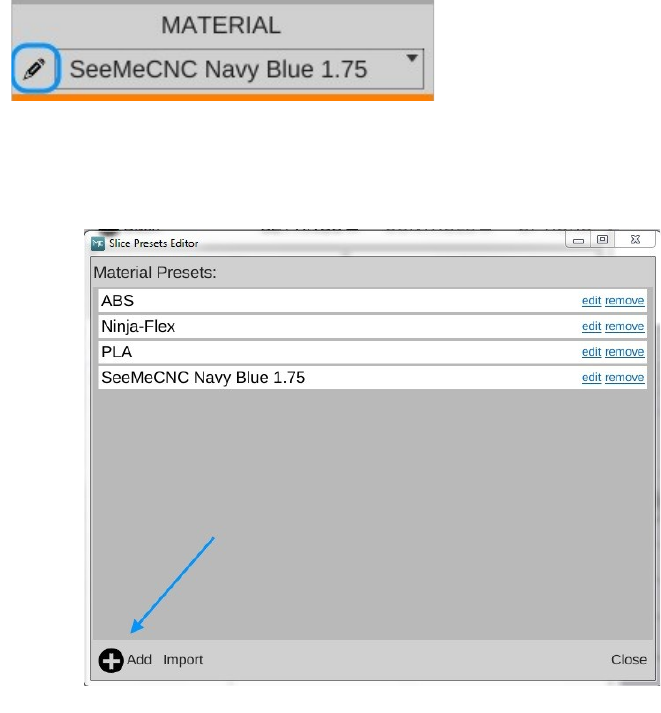
Rostock MAX v2 User's Guide
Each filament can have different heating requirements, even within the same type and color!
For example, it's not unusual to have two rolls of identical material require different hot end settings.
Bed temperatures tend to be less variable.
When you're working with a new roll of filament, I recommend printing a test object or two in
order to find out what the best temperature setting works best with that material. Note the settings on
the spool label, or add your own. This presents a nice opportunity to explain another feature of
MatterControl – material profiles! You'll notice a little pencil icon next to the material drop down
Click on that to bring up the preset manager.
The Material Presets list
shows you what pre-configured
material settings you've got available
to you. When you get a new roll of
filament in, you can easily keep track
of its settings by using this system.
Click on the Add button and we'll
create your first custom material!
5 – Matter Control Basics: Slicing - 57
Fig. 5.1-12: Material Editor.
Fig. 5.1-13:Adding a new material preset.
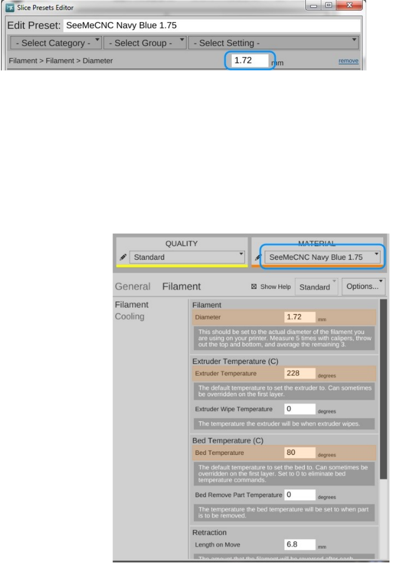
Rostock MAX v2 User's Guide
When you click on the Add button, you'll be presented with a screen that looks something like
the one shown on the below. The Edit Preset: field is where you can name this new material
configuration.
In this example, I've named it after the vendor and the material color. Since this is the first time
I've used this material, the only thing I know for sure is what the average filament diameter is. To enter
that, I picked Filament from the Select Category drop down, then from the Select Group drop down,
Filament was chosen again and finally Diameter was selected from the Select Setting drop down.
I then entered the filament diameter that I calculated using the process I outlined to you earlier.
Click on the Save button to commit your changes. Congrats, you've added your first custom
material profile!
After you've saved your new
profile, it will appear as the currently
selected material as shown to the
right.
Now say you've printed a test
cube and have decided that the print
might look better if you bumped up
the temperature 2 degrees. This is a
simple change to make.
5 – Matter Control Basics: Slicing - 58
Fig. 5.1-14: Setting up a new material.
Fig. 5.1-15: New material added!
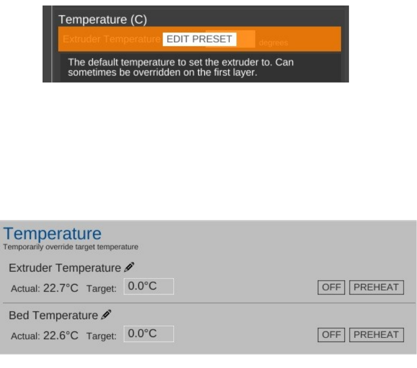
Rostock MAX v2 User's Guide
If you hover your mouse over the Extruder Temperature option, you'll see that the foreground
is covered by an EDIT PRESET button as shown below.
Clicking on the button will open up the materials editor and allow you to change the
temperature. It's as simple as that!
We've covered both the Basic and Standard settings for the slicing engine. Advanced is
something I'll cover later, so let's move on to the CONTROLS section.
The CONTROLS page is where you can manually control your Rostock MAX 3D printer. You
can heat the hot end or bed, as well as manually position the effector platform and extrude plastic.
The Temperature pane contains everything you need to manually control the temperatures for
both the hot end and the heated bed. MatterControl provides PLA and ABS presets. You can edit them
by clicking the pencil icons. You can also enter in a temperature and heat to that value by clicking on
the SET button that will appear as soon as you begin typing.
5 – Matter Control Basics: Slicing - 59
Fig. 5.1-16: Overriding a preset value.
Fig. 5.1-17: Temperature control pane.
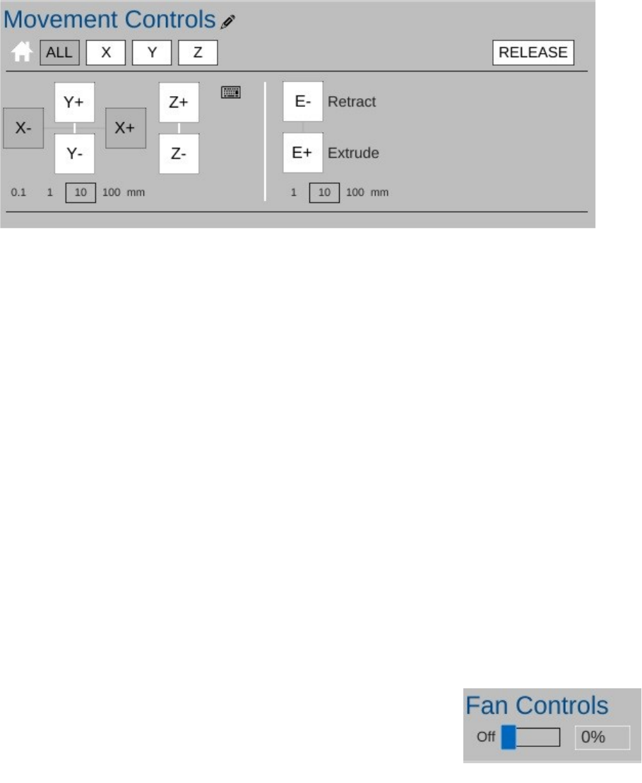
Rostock MAX v2 User's Guide
The Movement Controls pane contains controls that will allow you to manually position the
Rostock MAX's effector platform.
The row of buttons to the right of the little house icon control “homing” of the movement axes
in the Rostock MAX. Because the Rostock MAX is a delta configuration printer, the only buttons
active are the ALL and Z buttons – they perform the same action. Connect your printer if you haven't
already and click on one of them to see what I mean. The printer will home itself and await further
instructions. (Good robot! Have a Scooby Snack!) The RELEASE button will tell the Rostock MAX
to power down the stepper motors so that the axes can be moved by hand. This is handy when you
want to load new filament into the printer without having to turn it off first.
The axis motion is controlled by the X, Y and Z labeled + and – buttons shown above. Below
those four buttons are selectors indicating the step distance from 0.1mm to 100mm. The selected axis
will move the selected step distance with each mouse click. For this reason, please take special care
when you've got 100mm set for the step distance. The Rostock MAX is smart, but not THAT smart. It
relies upon you to not put the poor thing in an unlikely position. :)
The last set of buttons control the extruder motor – they're marked E- and E+ and can be used
to manually extrude filament. Note that they will only work if the hot end is up to operating
temperature! The amount of filament extruded (or retracted) is set using the step selector below the
control buttons for the extruder.
The Fan Controls allow you to manually control the layer fan on
your Rostock MAX. The fan control will not control the PEEK fan as that
is required to be on for the duration of the print job. You can turn the fan on
100% by clicking the control, your you can enter in a percentage value to
set it to a speed lower than full-on. I'll go over the use of the layer fan
when the Advanced settings are covered.
5 – Matter Control Basics: Slicing - 60
Fig. 5.1-18: Movement controls pane.
Fig. 5.1-19: Fan Control.
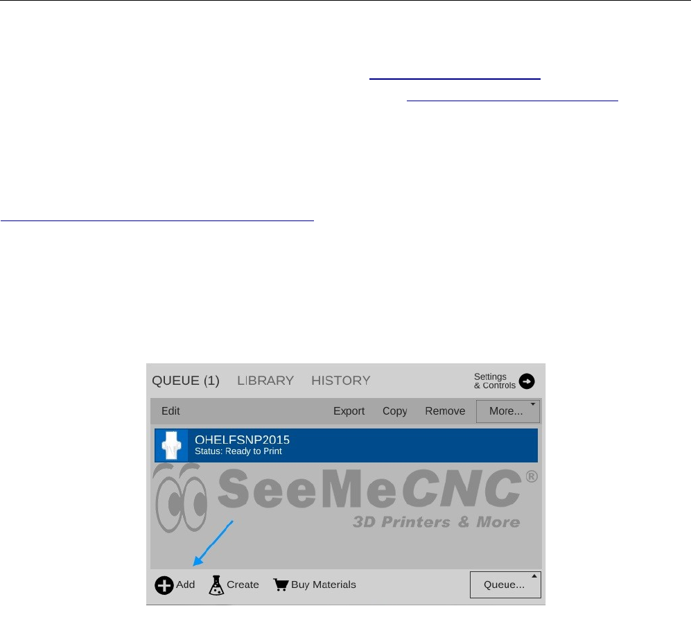
Rostock MAX v2 User's Guide
6 – MatterControl Basics: Loading and Printing Objects
We've previously worked with the small cube that MatterControl provided as an example. Now
we're going to cover loading and slicing an object from start to finish.
For this section, I recommend you head over to http://www.repables.com and find something
you'd like to print. I'm going to chose the Orion Key Chain (http://www.repables.com/r/151/) for my
example print. You don't have to make the same choice, but pick something geometrically “simple” in
order to make the learning process a bit easier.
Most (if not all) 3D printer slicing programs can read a file format called “STL”. (You can
learn more about this file format, including its origins, here:
http://en.wikipedia.org/wiki/STL_(file_format)) When you download a file from Repables or one of
the other free, online object repositories, you'll often get the file as a zip file. One nice feature of
MatterControl is the ability to select a zip file and MatterControl will transparently extract all the files
it knows how to read and load them up into your print queue.
To load a file into MatterControl, make sure you're on the Print Queue page and click the Add
button at the bottom right hand corner of the window.
6 – MatterControl Basics: Loading and Printing Objects - 61
Fig. 6.1-1: Adding an object to the print queue.
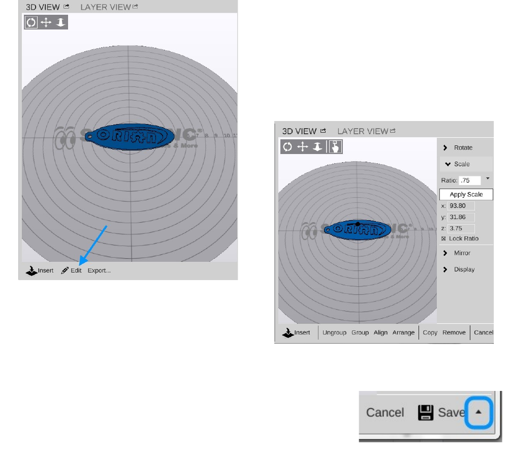
Rostock MAX v2 User's Guide
Navigate to where you've stored the STL or ZIP file and open it using the Open File dialog that
will appear.
Once you have the object loaded, click on the Settings & Controls button so we can make sure
your print settings are the way you want them.
For my print, I've decided to leave the QUALITY setting at Coarse and I'm using the tweaked
material values that I set up earlier.
Because the key chain is pretty large, I'm going to scale it down to 75% of it's original size.
This is an easy task in MatterControl.
Click on the Edit button as shown above.
This will modify the 3D View so the edit controls
are visible.
Click on the Scale button to access the scaling controls. As you
can see, I changed the value to 0.75 or 75% of its original size by
entering the value and clicking on the Apply Scale button. Click on the
small up arrow next to the Save button at the bottom of the window.
This will allow you to save the object under a different name if you don't
want to over-write the original.
6 – MatterControl Basics: Loading and Printing Objects - 62
Fig. 6.1-2: Editing an object.
Fig. 6.1-3: Scaling an object.
Save-As.
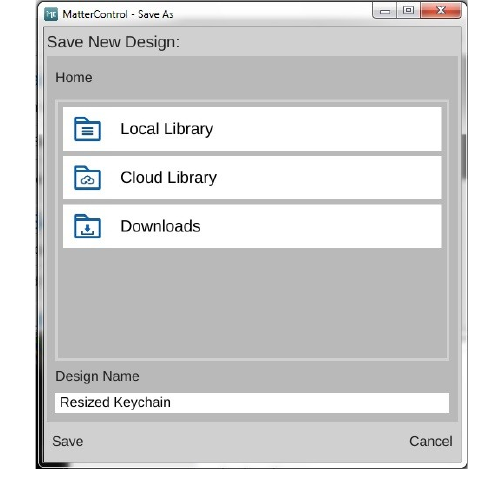
Rostock MAX v2 User's Guide
The Save-As dialog presents you with three
different locations you can save your changed
model. “Local Library” points to the local library
where MatterControl will store data on your local
computer. “Cloud Library” points to your cloud
storage at MatterControl HQ. You'll need to create
a free account with MatterControl in order to use
this option.
6 – MatterControl Basics: Loading and Printing Objects - 63
Fig. 6.1-4: Saving the scaled object.
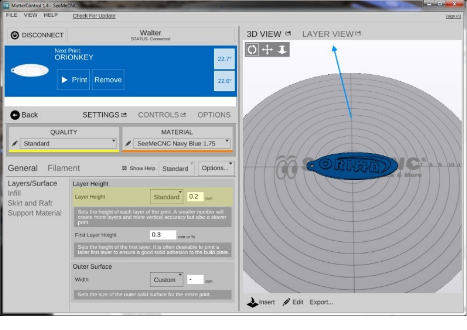
Rostock MAX v2 User's Guide
Before we start this print, let's take a second to examine a feature of MatterControl – the Layer
View. If you've not sliced this object yet, you'll like see the text “Press 'generate' to view layers”. Go
ahead and do that now.
6 – MatterControl Basics: Loading and Printing Objects - 64
Fig. 6.1-5: The Layer View.
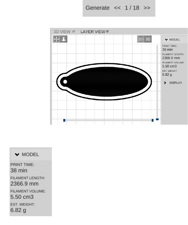
Rostock MAX v2 User's Guide
When it finishes, the layer view will display the first layer of your print job.
You'll notice right off the skirt that I covered previously. It's important to make sure that the hot
end is primed by the time it begins to print your part!
At the bottom of the window you'll see some controls that will allow you to either re-slice the
object (Generate) or view the individual print layers.
The controls will show you how many layers are on this object as well as
what the layer number is that you're currently viewing. You can navigate
forward and backward through the layers by using the >> and << buttons. If
you want to jump to a specific layer, you can enter it in to the box and click
Go.
After slicing the object, MatterControl will display a few statistics about
the current print in the Layer View window. This can be handy information
if you're selling your services and need to know how much a particular part
is going to consume in both time and materials.
Go ahead and click the Print button and get your object printing!
6 – MatterControl Basics: Loading and Printing Objects - 65
Fig. 6.1-6: First Layer.
Fig. 6.1-7: Model Stats.
Rostock MAX v2 User's Guide
After the print finishes, you should have a little part that looks something like the photo below
(if that's what you printed).
6 – MatterControl Basics: Loading and Printing Objects - 66
Fig. 6.1-8: Finished print!
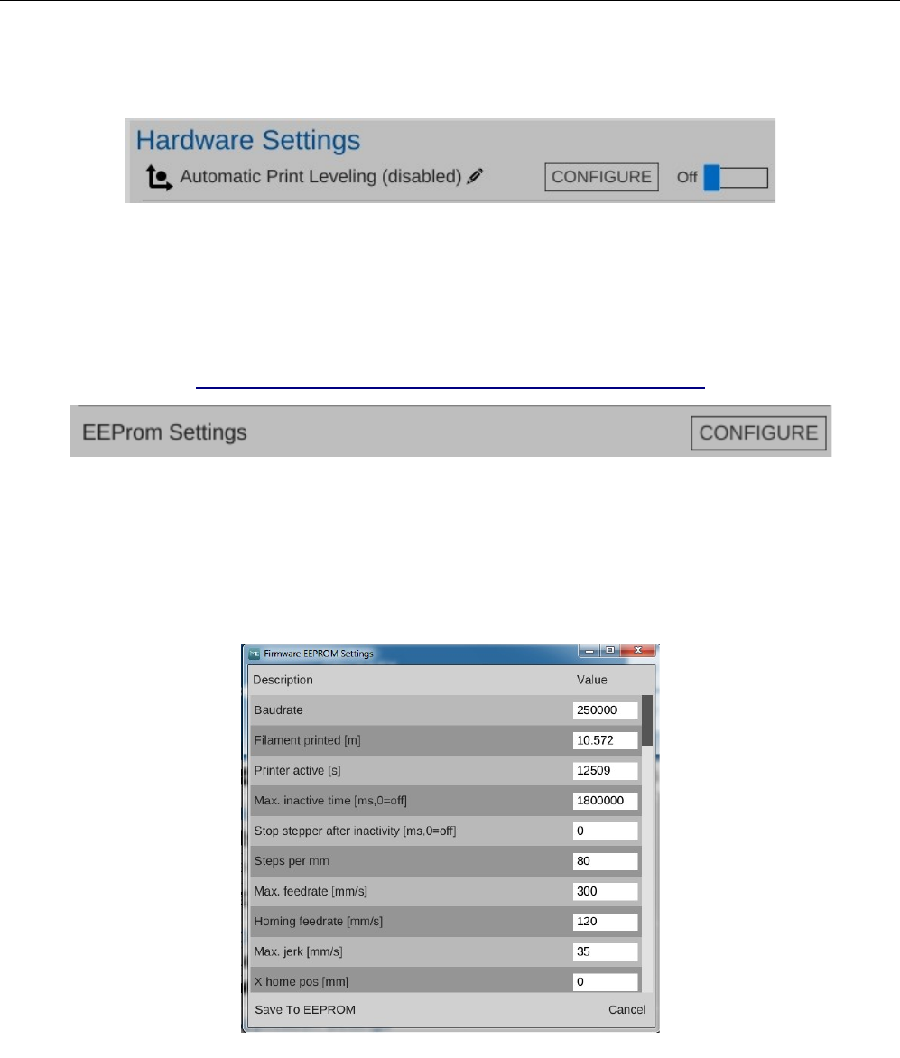
Rostock MAX v2 User's Guide
7 – Advanced MatterControl: Configuration
MatterControl includes a number of basic configuration options that you can use to set up
things like your default slicing engine, change EEPROM settings, etc.
Let's go over each one as they appear on the MatterControl Configuration pane.
MatterControl includes a bed leveling feature that when properly configured, can assist with issues that
can arise from an un-level bed. Note that this will NOT calibrate a delta printer! What it can do is help
improve first layer performance on an already calibrated printer.
SeeMeCNC has put together a nice video that illustrates the process quite effectively:
https://www.youtube.com/watch?v=z6ymbr-AMew
The EEPROM Settings configuration option will allow you to edit firmware parameters that are
stored on the controller inside your Rostock MAX. Please take special care when changing EEPROM
values. An improperly set configuration parameter can cause your Rostock MAX to misbehave.
Sometimes rather dramatically. :)
Here's an example of the things you can change under the EEPROM Settings configuration:
7 – Advanced MatterControl: Configuration - 67
Fig. 7.1-1: Automatic Print Leveling.
Fig. 7.1-2: EEPROM Settings.
Fig. 7.1-3: EEPROM Table Editor.
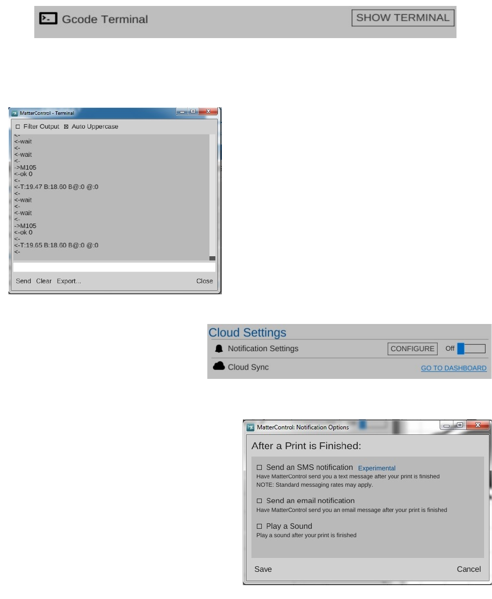
Rostock MAX v2 User's Guide
The G-Code Terminal is where you can directly interact with the firmware on your Rostock
MAX. When you first open the G-Code Terminal, you'll be presented with a window that looks similar
to the one below:
You'll notice that the display will scroll as new
information comes in from the Rostock MAX. This is
how MatterControl is able to continually update things
like the temperature displays. In order to be able to
use the terminal for basic tasks, you'll need to click on
the Filter Output check box that's at the upper left
corner of the window. This will filter out the telemetry
information coming from the Rostock MAX's
controller and allow you to directly interact with the
printer without having the output interleaved with the
periodic information that the Rostock MAX transmits.
MatterControl provides the ability
to remotely monitor your Rostock MAX
printer from anywhere in the world. To
learn more about this service, click on the
GO TO DASHBOARD link in
MatterControl.
By default, MatterControl will play a bell
sound when the current active print job completes.
However, you can change this behavior via the
Notification Settings configuration screen.
You'll be able to configure MatterControl
to send you an email or text message when your
printer completes a job. Note that this feature is
only available when you're using MatterControl to
run a print job. If you're printing from the SD
card, notification won't be possible.
7 – Advanced MatterControl: Configuration - 68
Fig. 7.1-4: Accessing the G-Code terminal.
Fig. 7.1-5: G-Code terminal window.
Fig. 7.1-6: Cloud Settings.
Fig. 7.1-7: Notification Options.
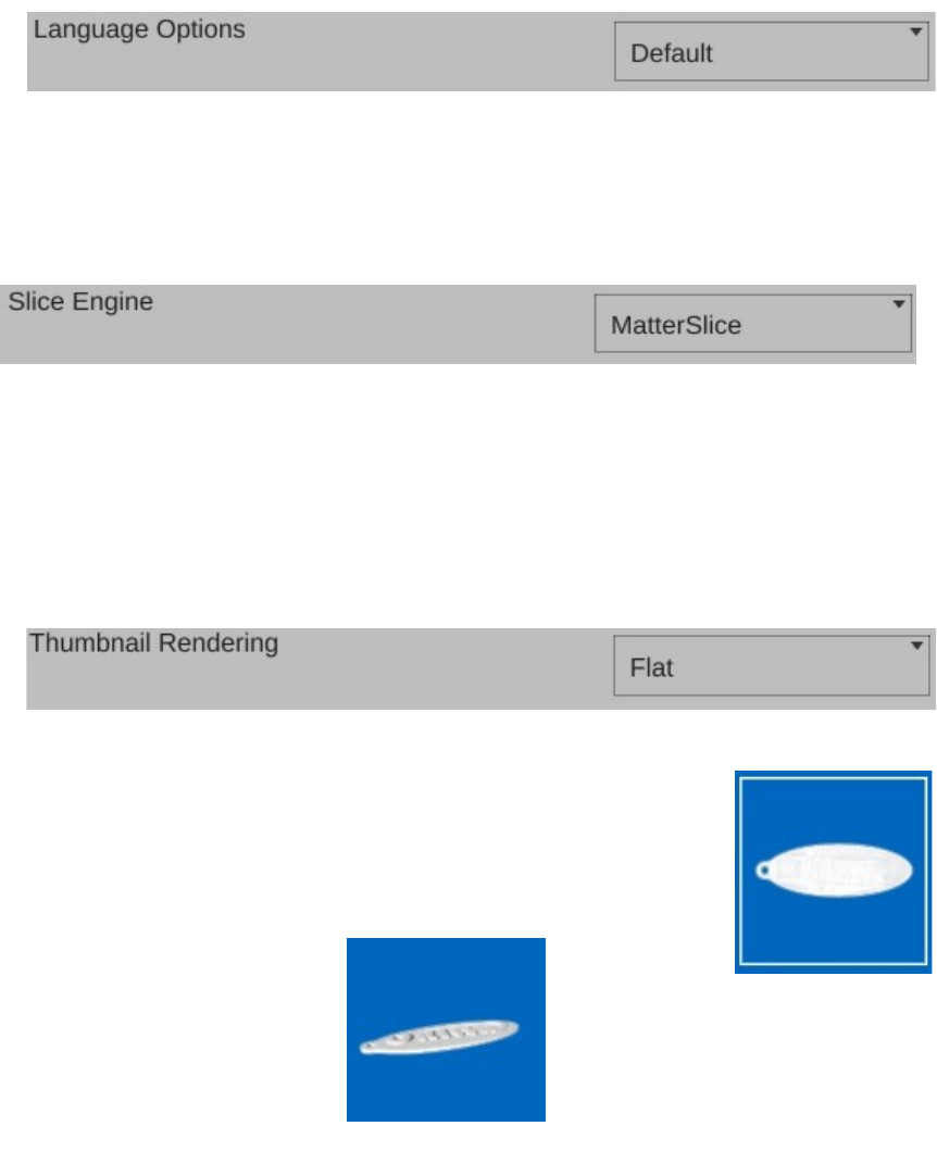
Rostock MAX v2 User's Guide
This particular configuration option should be pretty self-explanatory. I hope.
The Slice Engine configuration will allow you to choose which slicer that you want to use in
order to prepare your model for printing. By default, MatterControl uses the MatterSlice slicing
engine that was developed by the MatterControl team.
You also have the option of choosing Slic3r or CuraEngine to do your slicing. Selecting a
different slicing engine will change the options available on the Settings pane, but shouldn't disturb
those you've changed in the past. The MatterControl team has tried to keep common names across
slicing engines, so the most noticeable change you'll see will be additional options supported by one
slicer but not the others.
The Thumbnail Rendering option will change how the parts in the
print queue are shown. The default “2D” thumbnail will look something
like the example in Fig. 7.1-11. “3D” will appear as a slightly tilted model
as shown in Fig. 7.1-12.
7 – Advanced MatterControl: Configuration - 69
Fig. 7.1-9: Choosing a slicer.
Fig. 7.1-8: Language Selection.
Fig. 7.1-10: Thumbnail Rendering.
Fig. 7.1-11: 2D.
Fig. 7.1-12: 3D.
Rostock MAX v2 User's Guide
The Change Display Mode will allow you to switch between “Normal” and “Touchscreen”.
The touchscreen interface is optimized for that type of input method. You'll need to restart
MatterControl when changing the display mode.
Clear Print History will allow you to clear all the items from the History display.
Theme/Display Options allows you to change the primary color that the user interface renders
in. The top row of color selections provide the selected color against a light background. The second
row of color selections provide the selected color against a dark background.
7 – Advanced MatterControl: Configuration - 70
Fig. 7.1-15: Display theme.
Fig. 7.1-14: Clearing the print history.
Fig. 7.1-13: Change Display Mode.
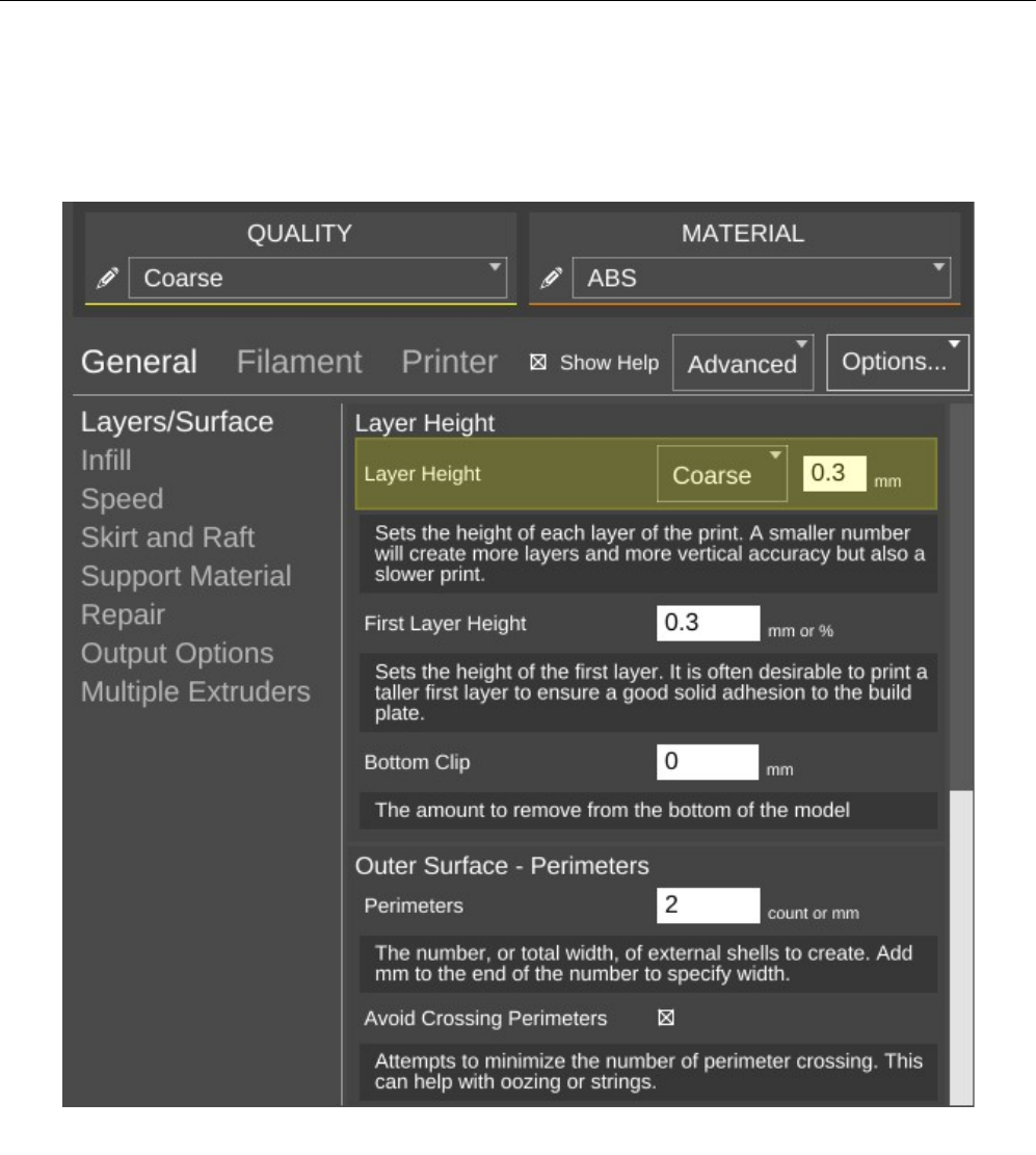
Rostock MAX v2 User's Guide
8 – Advanced MatterControl: Settings – General
MatterControl offers three “classes” of settings that have a direct effect on how your printer
works. General covers elements that relate to how the plastic is laid down. Filament covers
parameters specific to the type of filament that you've chosen to print with. Printer handles those
remaining parameters that describe the physical printer you're currently using to print with.
Let's start this overview on the main page of General, Layers/Surface.
8 – Advanced MatterControl: Settings – General - 71
Print layers & perimeters.
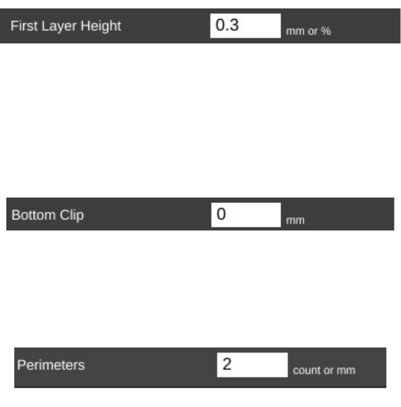
Rostock MAX v2 User's Guide
The first parameter is Layer Height. We've covered this one before, but I wanted to point out
something that I didn't go into a lot of detail about earlier. You'll notice that the field has a yellowish
highlight to it. That means that the value exists in the currently selected QUALITY profile. If you
look carefully, you'll see that the highlight color matches the thin colored line under the QUALITY
drop down. (This same effect holds true for MATERIAL profiles, but the color is orange.)
Any time you add a Print parameter to a preset profile, it will be highlighted just as the Layer
Height field is in the example. Note that you can use any of the Print, Filament, or Printer
configuration parameters within either of the QUALITY or MATERIAL profile editors.
The First Layer Height parameter allows you to set the thickness of your first layer. Having a
thicker first layer will help provide a good base to build the rest of the part on as the thicker (and thus
wider extrusion) will help improve the adhesion to the bed. If your first layer isn't any good, the part
could eventually separate from the bed and ruin the print job.
Bottom Clip allows you to tell the slicing engine that you'd like to “clip off” a specific amount
from the bottom of the model. For example, say you've got a 200mm tall model, but you only want to
print the top 50mm or so. You can enter 150 into the Bottom Clip field and when the slicer generates
the G-Code for the print job, it will begin slicing 150mm up from the bottom of the model.
Perimeters dictate how thick the “skin” of your model is. 2 or 3 perimeters are good for most
parts, but if you want a really strong exterior wall, you can make the perimeter count as high as you
feel you need it. To get an idea of how thick the skin will be, you multiply the perimeter count by the
extrusion thickness (we'll get to that parameter in a bit). For example, if you have a 0.5mm nozzle,
chances are your extrusion thickness will be set to 0.5. 2 perimeters will give you a skin thickness of
1mm. You also have the option of specifying the perimeter thickness in millimeters instead of
perimeter counts.
8 – Advanced MatterControl: Settings – General - 72
First Layer Height.
Bottom Clip.
Perimeters.
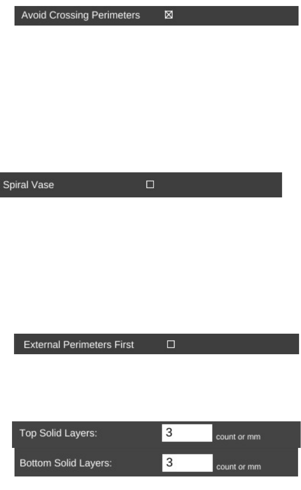
Rostock MAX v2 User's Guide
When Avoid Crossing Perimeters is enabled, the nozzle path will not cross a part perimeter
during travel moves. This will help reduce the opportunity for stringing or oozing since the nozzle tip
is rarely over open air. For instance, if the tool path would normally cause the nozzle to travel from
one side of the part to the other, it would cross at least two perimeters and may leave strings of material
in its wake as it moves. If it is set to not cross perimeters, it will cause the nozzle to trace a perimeter
back to the nearest point where it can begin printing again instead of jumping straight across to the new
extrusion position.
Spiral Vase mode allows you to print things like vases or other open top, single-wall objects in
one continuous layer. What happens is that instead of the slicer raising the nozzle up a full layer height
for each new layer, it gradually increases the Z height as the print progresses. This results in a perfectly
seamless object, which can be important for artistic prints such as vases. When you're printing a vase
or similar object, you'll want to make sure that you set the top layer count to zero to prevent the vase
getting a “lid” that you'll have to cut off.
By default, objects are printed from the inside features to the outside. If you want to reverse
this process, enable External Perimeters First. This will cause the outside of the model to be printed
before the interior features.
The Top and Bottom solid layer parameters dictate how thick the top and bottom surfaces of
your object are when printed. These two parameters fulfill essentially the same function as the
Perimeters parameter, but for the top and bottom of the part. You can calculate your top & bottom
thickness by multiplying the solid layer count by the layer height. For example, 5 top layers will result
in a final top thickness of 1mm if your layer height is 0.2mm. You also have the option of specifying
the top and bottom thickness in millimeters instead of layers.
8 – Advanced MatterControl: Settings – General - 73
Avoid Crossing Perimeters.
Spiral Vase.
External Perimeters First.
Top & Bottom solid layers.
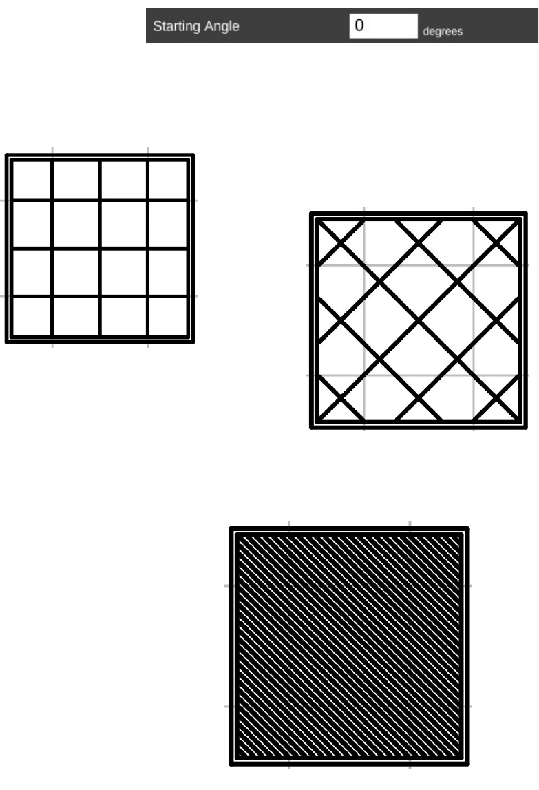
Rostock MAX v2 User's Guide
The next page in Print is called Infill and covers how the interior of your part is filled. While I
covered Fill Density and Infill Type earlier, the Advanced mode adds two new parameters.
The Starting Angle parameter allows you to control the orientation of the infill. For example,
an infill type of GRID with a starting angle of zero degrees is going to look like this:
Now if you change the starting angle to 45 degrees, you'll end up
with an infill pattern that looks like the example below.
Note that changing the starting angle will also change the angle in which the top and bottom
layers are printed. You can see this in the image below – this shows the second layer as it would be
printed.
8 – Advanced MatterControl: Settings – General - 74
Grid infill.
Grid @ 45 degrees.
Top & bottom layer pattern.
Starting Angle.
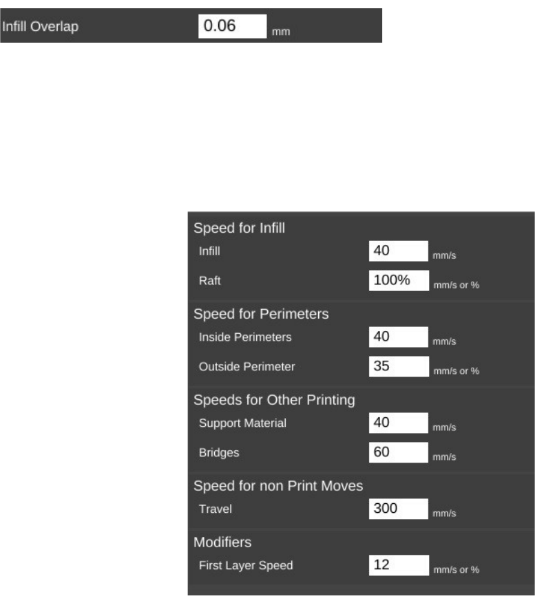
Rostock MAX v2 User's Guide
Infill Overlap is used to adjust how well the infill pattern attaches to the inside perimeter of the
part. A good infill will have a solid connection to the inside perimeter of your part, and the structural
integrity of your part depends on this.
The Speed page covers parameters that control how fast various features of the object are
printed. The speeds are listed in mm per second, or as a percentage of a related speed parameter.
The speed parameters are pretty self-
explanatory, especially if you've got the Show
Help check box set. However, there's a couple of
points I'd like to cover about printing speed.
First of all, there is a relation between your
print speed and the temperature you've set for the
material you're printing with. The basic rule is, the
faster you go, the hotter you print. This is because
as the hot end extrudes plastic, it's constantly being
cooled by the cold filament that's coming in.
Setting the extrusion temperature higher
allows the hot end to melt the incoming plastic at a
faster rate. This allows you to print more quickly.
The relation between print speed and extrusion
temperature is one of those things you'll get a feel
for as you gain experience with your printer.
You'll quickly learn that the Rostock MAX
will “talk” to you if you're printing too rapidly for
a given temperature. The extruder will begin to “skip” periodically (or frequently, depending on how
fast you're going). A skipping extruder has a very distinct sound – it's kind of a light bump or
knocking. If you watch the nylon gear that you use to manually feed filament, you'll notice that it will
briefly rotate in the opposite direction at the same time you hear the skipping sound. If you draw a line
on the face of the gear, you can spot this motion more easily. The skip is caused by the hot end's
inability to melt the material is rapidly as is required. The pressure builds up until the stepper motor
can no longer generate the force required. At this point the tension in the filament is released like a
spring and the filament pushes back with enough force to cause the stepper motor to skip steps,
resulting in a short reverse rotation.
8 – Advanced MatterControl: Settings – General - 75
Infill Overlap.
Print Speeds.
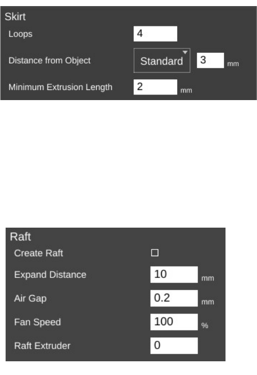
Rostock MAX v2 User's Guide
Secondly, there is also a direct relation between print speed and print quality. In the image
above, you'll notice that the speeds for print moves vary a bit. This is because some features don't
require a focus on surface quality.
Perimeters are a great example of this. You'll note that the inside perimeter speed is 40mm/sec,
while the outside perimeter is 35mm/sec. The inside perimeter will never been seen after the print is
finished so it can be printed at a higher rate. However, you want the visible surface of the print to be
smoother and more consistent, so you print the outside perimeters a bit more slowly.
The last bit about speed settings I want to cover is the first layer speed. You'll see that it's really
slow. The reason for this is that while hot plastic loves to stick to hot plastic, hot plastic doesn't like
sticking to other things as much. By going slowly on the first layer, you're giving the material time to
get a good grip on the surface of the bed. This is known as “part adhesion”. When a part comes
unstuck from the bed during a print, it's ruined. This isn't so bad when you're five minutes into a print,
but you'll be ready to flip a table when it happens 18 hours into a 19 hour print.
The Skirt and Raft page covers settings that control how the hot end is primed at the beginning
of a print job as well as features that help the part stick to the bed.
The first section covers the Skirt feature.
A skirt in this context is basically a series of
single-layer loops printed around the perimeter of
the part. This acts as a method to “prime” the hot
end with material before the actual part begins to
print. Loops defines how many times you want to
go around the print. This is tied to the Minimum
Extrusion Length parameter. If the number of loops you specify are not enough to meet that
minimum length, additional loops will be added automatically.
The Distance from Object parameter dictates how far away the loop stands off from the part
outline. If you set the distance to zero, the skirt will become a “brim”. It will result in the loops being
printed connected to the first layer of your print. This can give small parts a first layer that has a larger
surface area to improve part adhesion. Since the brim is only a single layer thick, it's usually pretty
easy to remove after the print job has completed.
I mentioned earlier that hot plastic really
loves sticking to hot plastic, but not so much to
other things. If a brim isn't doing the job for you,
you can try a Raft.
8 – Advanced MatterControl: Settings – General - 76
Skirt parameters.
Raft parameters.
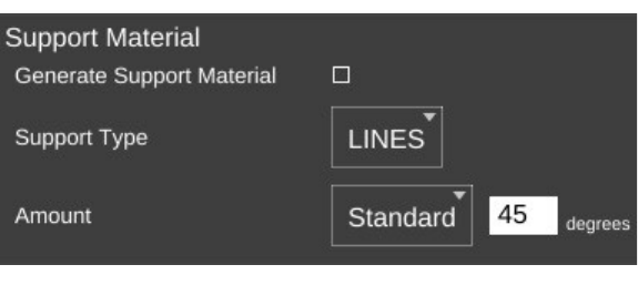
Rostock MAX v2 User's Guide
When in Standard mode, the Raft setting was simply an on/off setting. In Advanced mode,
you've got a lot more control over how the raft is laid down.
Expand Distance is the distance you'd like the raft to exceed the base area of the part you're
printing. You may want to adjust this parameter if the part you're printing is larger than the bottom
contact point on the bed. A larger raft will help to support the part more effectively.
Air Gap defines how much space you want between the top surface of the raft and the bottom
surface of your part. This gap helps make it easier (or even possible!) to remove the raft from your part
when it's finished. As mentioned in the help text, a good air gap is one half the diameter of the nozzle.
For example, if your nozzle is 0.5mm, you'd want an air gap of 0.25mm.
You can use the Fan Speed setting to cool the raft as it's being printed. This is typically only
used when printing with PLA.
If you've added a second extruder to your Rostock MAX, you can specify which one should be
used for rafts by setting the Raft Extruder value to the index of the extruder you want to use. If you
don't have multiple extruders, you can leave this set to zero.
The Support Material page provides detailed settings on the use of support material if the part
you're printing requires it. While I covered the basics of support earlier, I'm going to get a bit more in-
depth on it here.
Checking Generate Support
Material will allow you to configure
support for your part. Support is required
when a part has an overhang or other
angled feature that would result in little or
no physical support to put a print layer on.
The Support Type selection allows you to
define the geometric pattern for the support
structure. You have GRID and LINES.
These patterns were covered earlier, so I won't cover them again here. The new parameter you have to
work with in Advanced mode is called Amount.
8 – Advanced MatterControl: Settings – General - 77
Support Material.
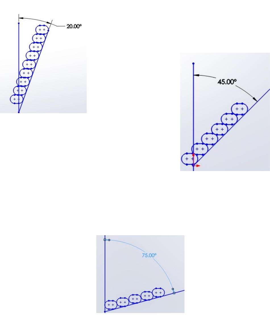
Rostock MAX v2 User's Guide
Amount is expressed in degrees from vertical and tells the slicing engine to generate support
for any feature that meets or exceeds the specified angle. In the setting shown above, the slicing engine
will generate support at points where the model “overhangs” 45 degrees or more from vertical.
When you've got a part feature that's only 20 degrees or so, each
layer can easily be supported by the layer underneath. This is because
as the part height increases, the horizontal dimension increase is less
than the extrusion width. This means that each new layer has a solid
foundation to adhere to as it's being applied.
As you can see when your angle increases to 45 degrees,
each layer has much less surface area to adhere to as you print.
This is where support comes in handy. It provides that underlying
structure for those layers to build upon.
As the angle increases, the underlying surface area for each layer becomes smaller and smaller
until there's simply not enough surface for the next layer to adhere to. In these instances, support
material is practically a requirement if you want your part to print at all.
Now that you've got a good handle on why support can be useful, let's go over the parameters
that you can tune to get good support that is easily removable from your part.
8 – Advanced MatterControl: Settings – General - 78
20 deg. overhang.
45 deg. overhang.
75 deg. overhang.
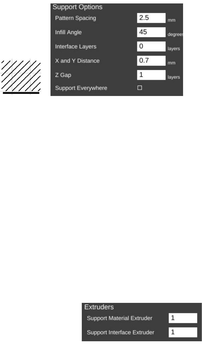
Rostock MAX v2 User's Guide
Pattern Spacing controls the distance
between each “track” of support that is laid
down to support your part. The wider the
spacing, the less support that is printed.
Infill Angle adjusts the angle at which
the support structure is built.
Interface Layers allows you to specify solid layers interspersed with the support material.
This comes in handy when using multiple extruders. For example, if you're printing a part in PLA with
lots of support, you can generate all the support with PLA, and then have 5 or 6 interface layers of PVA
(a water soluble filament). The print would then only be in contact with the PVA interface layers and it
would be a flat layer to print on. When finished you can dissolve away the interface layers and the rest
of the support falls off the part cleanly.
X and Y Distance dictates how far away the support structure will be from the part you're
printing. You want it as close as you can get it without it actually touching the surface of the part. The
default of 0.7mm seems to work out pretty well.
Z Gap specifies how many layers should separate the support material from the part. This
parameter contributes to how easy or difficult it is to remove support material from the part once the
print is finished. If you have too little gap, the support material will have more of a grip on the part
surface making it difficult to remove. If the gap is too large, the support material won't be able to do its
job very effectively.
If Support Everywhere is checked, you're probably going to get more support material than
you bargained for. If you have an internal feature of a part, this may be required in order to support it,
but keep in mind that it will also add support to features like horizontally oriented holes, which don't
normally need support to print properly.
If you've got multiple extruders on your Rostock
MAX, these parameters allow you to specify which
extruder is used for generating support structure.
8 – Advanced MatterControl: Settings – General - 79
45 Deg. Infill Support Options.
Extruder Settings.
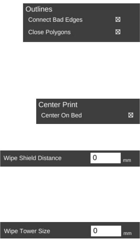
Rostock MAX v2 User's Guide
The Repair page contains a couple of settings the govern how (and if) the slicer will attempt
any repair of invalid part models.
Sometimes modeling programs will create a model that
isn't “water tight”, meaning it's got gaps in the surface. These
gaps make it difficult for the slicing engine to do its job and in
some cases can cause the slicing operation to fail. The Repair
option is MatterSlice's attempt to help fix these issues if they're
detected.
On the Output Options page is a single parameter, Center On Bed. This will automatically
center the model on the print bed when you load it. If you don't want that to happen, just un-check the
box.
The Multiple Extruders page has two settings that control
how ooze & filament wipes are handled.
The Wipe Shield Distance specifies how far away from the part you want what is commonly
known as an “ooze shield” to be placed around the part. In a two extruder system, the unselected hot
end will create this “shield” in order to avoid dripping or oozing plastic on other parts of the model.
Wipe Tower is used when changing extruders.
The active nozzle creates a tower of the specified size
and will use it to wipe the nozzle in order to reduce the
possibility of oozing or dripping material on the model
while the other extruder is active.
8 – Advanced MatterControl: Settings – General - 80
Outlines.
Center Bed.
Wipe Shield.
Wipe Tower Size.
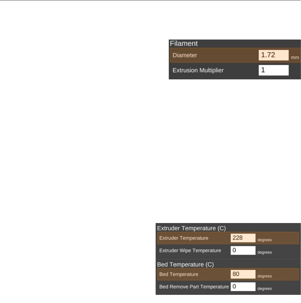
Rostock MAX v2 User's Guide
9 – Advanced MatterControl: Settings – Filament
The Filament tab allows you to change parameters that deal with the current filament you're
printing with. The Filament page is divided into three categories; Filament, Temperature, and
Retraction.
The filament Diameter parameter tells the slicing
engine the size of the material you're printing with. When
starting a new roll of material, you should pull off about 2
meters of material and check it in 10 spots along the
length using a digital caliper. Average those samples and
plug the result into the Diameter field. This is a good
way of getting a good estimate of the material you're actually using. This allows the slicing engine to
deliver more consistent results instead of depending on the generic size of the material.
You'll notice that the Diameter field is highlighted in orange. This means that the parameter is
part of a predefined material configuration. When using a new spool of material for the first time, it's a
good idea to create a new profile for it when you're taking the sample measurements of the diameter. A
good rule of thumb is to include the date you started using the filament as part of the material profile
name. Note the date on the spool label if it has one and add one if it doesn't. This will help you track
individual spools of the same color and manufacturer.
The Extrusion Multiplier parameter allows you to tweak the flow rate of the material coming
out of the hot end. A basic rule of thumb on this is to restrict the max value to 1.1 and the minimum
value to 0.9. Note that these aren't hard limits but are simply a guideline to utilize until you're familiar
with the effects this parameter has on print jobs.
The Extruder Temperature is the
temperature for the hot end, Extruder Wipe
Temperature is used to set the hot end temperature
for wipe operations.
Bed Temperature is the temperature for the
heated bed, Bed Remove Part Temperature is the
temperature at which the part can be removed.
Note that neither the Extruder Wipe
Temperature, nor the Bed Remove Part
temperature are applicable to the Rostock MAX v2.
9 – Advanced MatterControl: Settings – Filament - 81
Setting the filament diameter.
Setting temperatures.
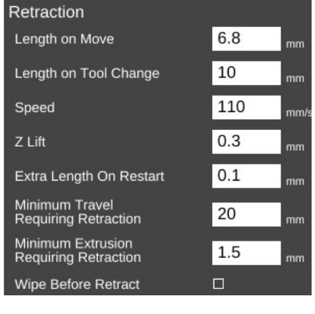
Rostock MAX v2 User's Guide
As you can see, both of these are part of the currently selected material profile. Each material
class has a general temperature range for the hot end. For example, ABS extrusion temperatures can
range from 195 to 240C. PLA likes anywhere from 180 to 215. The specific temperature that your
material works best at varies by manufacturer and chemical blend. It's not unusual to see different
“sweet spot” temperatures among identical colors of material, even with the same manufacturer.
The Bed Temperature parameter typically has a lot less of a range than the extrusion
temperature does. A good rule of thumb here is 55-60C for PLA and 80-100C for ABS.
Retraction covers how the slicer “retracts” the filament during travel operations where it's not
actually laying down plastic. Good retraction
settings help keep your part free of little strings
and blobs during printing.
Length on Move specifies how much
filament will be backed out of the hot end during
a non-printing move.
Length on Tool Change is specific to
multi-extruder systems. If the slicer is changing
to a new extruder, it will retract the material out
of the current hot end by this much. This works
in conjunction with wipe towers and wipe
shields.
Speed dictates how fast the extruder drive
will pull the filament out of the hot end. Higher
speeds can assist in preventing already-melted plastic from oozing or leaving strings on the part being
printed. It also controls how fast the filament will be returned to the hot end when the non-printing
move has completed.
Z-Lift is used to lift the nozzle off of the part as each retract finishes. This can help prevent
blobbing.
Extra Length on Restart is used to extrude some extra filament after resuming from a retract
operation.
Minimum Travel Requiring Retraction is used to prevent retractions during very short moves
when retraction isn't really necessary. When executing a non-printing move, the nozzle will have to
travel at least this distance in order to trigger a retraction action.
9 – Advanced MatterControl: Settings – Filament - 82
Configuring retraction settings.
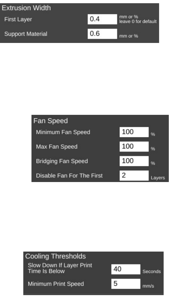
Rostock MAX v2 User's Guide
Minimum Extrusion Requiring Retraction specifies how much filament must be extruded
before a retraction operation is permitted. This helps prevent instances where a retraction operation
would occur before the hot end had the opportunity to actually extrude material.
Wipe Before Retract will wipe the nozzle before starting the retract process. This helps to
eliminate stringing and oozing.
The Extrusion page has but two
parameters.
First Layer allows you to specify the
width of the first layer as it's laid down.
Setting the value to greater than 100% can
assist in first layer adhesion.
Support Material will allow you to tune the extrusion width used when printing support
material.
The Cooling page covers parameters relating to layer cooling.
The Fan Speed section controls how and when the cooling layer fan is used.
Minimum and Maximum Fan Speed controls
the lower and upper limits of how fast you want the fan
to go when it's enabled. If you specify a minimum
speed, the slicing engine will automatically vary the
speed of the fan between the min & max values,
depending on the location being printed. For larger
parts, the slicing engine may run the fan more slowly
than it would for smaller parts.
Bridging Fan Speed covers the speed that the
fan should run at when the slicer is creating a filament bridge. A bridge is basically a free-hanging
length of filament with no support below it. Some materials like PLA form excellent bridges if cooled
while being extruded.
Disable Fan For The First n Layers allows you to make sure that the fan isn't activated during
the crucial first few layers of a print. You typically don't use the fan for at least the first two layers in
order to help ensure good bed adhesion.
Cooling Thresholds allow you to slow the
print speed down during a print if needed. If the
current layer will require more than the specified
time to print, the slicing engine will automatically
slow the print speed down to meet this goal.
9 – Advanced MatterControl: Settings – Filament - 83
Setting cooling fan speeds.
Setting cooling thresholds.
Extrusion width.
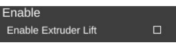
Rostock MAX v2 User's Guide
This can be important because if you don't use a fan, a layer will need time to radiate its excess
heat before the next layer is applied. If the material isn't cooled, or given time to cool via radiation,
heat can build up in the underlying layers and cause curling and other undesirable effects.
Minimum Print Speed can be used to ensure that the printer doesn't slow down TOO much,
which can cause it's own heating problems. For example, if you're printing too slowly, the presence of
the nozzle moving over the surface can cause heating to areas adjacent to the nozzle tip which can
cause blobbing or layer deformation.
Enable Extruder Lift if set, will cause the hot end to
lift up from the part to allow cooling.
Note that none of the fan options will come into effect unless you've enabled the operation of
the fan. I'll cover that in the next section.
9 – Advanced MatterControl: Settings – Filament - 84
Enabling extruder lift.
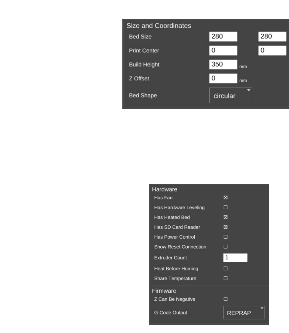
Rostock MAX v2 User's Guide
10 – Advanced MatterControl: Settings – Printer
The Printer section covers items that are specific to the printer being used for the current print job.
The Print Area page covers
parameters that describe the mechanical
features of the printer.
The Bed Size fields cover the width
and length of the bed. Since the Rostock
MAX has a round bed, you'll see that both
figures are the same, the Print Center has
been set to 0,0 (the center of the circle) and
the Bed Shape has been set to circular.
The Rostock MAX bed size should
be set to 280/280.
The Build Height parameter should be set to the highest practical build height. In the case of
the Rostock MAX, this is set to 350mm.
Z Offset can be used if you want to set a specific adjustment to the z position of the G-Code
when it's created by the slicing engine.
The Bed Shape parameter dictates what bed type is shown in the 3D viewer.
The Hardware section allows you to specify
what features are installed on your Rostock MAX v2.
Has Fan, when checked will allow the
slicing engine to control the layer cooling fan.
Has Hardware Leveling should be set if
you've added a mechanical depth probe for leveling
the bed on your Rostock MAX.
Has Heated Bed should be checked for the
Rostock MAX v2. This allows the slicing engine to
control the heat of the bed.
Has SD Card Reader should be checked for
the Rostock MAX v2. This allows MatterControl to
save STL and G-Code directly to the SD card if it's
installed in the Rostock MAX.
10 – Advanced MatterControl: Settings – Printer - 85
Setting printer size and coordinates.
Basic hardware settings.
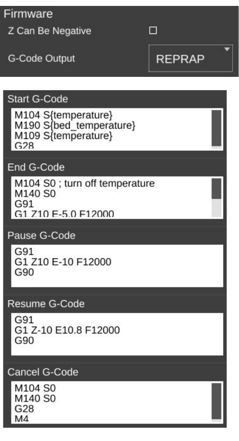
Rostock MAX v2 User's Guide
Has Power Control indicates whether or not your printer can control its own power supply. In
the case of the Rostock MAX, this should be left unchecked.
Show Reset Connection This will enable a “reset” button that will reset the connection when
pressed. It can be used as an emergency stop on printers that support it.
For a stock Rostock MAX, Extruder Count should be set to 1. If you add an additional
extruder in the future, you can tell the slicing engine about it here.
Heat Before Homing When checked, this will cause the hot end to be heated before the printer
is sent to its home position, instead of after.
Share Temperature is used when utilizing multiple extruders that share the same heat source.
The Firmware section allows you to tell the
slicing engine about the firmware you're using with
your Rostock MAX.
Z Can Be Negative can be checked if the
firmware you're using on your Rostock MAX will
accept Z positions below zero. Leave this unchecked
if you're using the stock Rostock MAX firmware.
G-Code Output specifies what “flavor” of G-
Code should be created by the slicing engine. For the
Rostock MAX, this should be set to REPRAP.
The next page is called Custom G-Code and
allows you to customize the code sent for five
different print events. Unless you're familiar with
what the listed G and M codes do, please don't
modify the defaults shown.
Start G-Code is inserted into the G-Code
output right after the temperature setting. If you have
the commands to set the temperatures in this section,
they won't be generated outside of this section. You
can also include values from other sections such as
“first_layer_temperature”
End G-Code is inserted into the output at the
very end, after all print operations have been
completed.
Pause G-Code is sent when the Rostock
MAX is paused during a print.
10 – Advanced MatterControl: Settings – Printer - 86
Firmware type.
Custom G-Code settings.
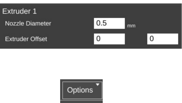
Rostock MAX v2 User's Guide
Resume G-Code is sent when the Rostock MAX is resumed.
Cancel G-Code is sent when you cancel a print job from MatterControl
The last page for the Printer tab is called Extruder. This page allows you to configure each
extruder you have installed in your Rostock MAX.
Nozzle Diameter specifies the
diameter of the currently installed nozzle
in the hot end.
Extruder Offset allows you to specify the offset from the center of the effector platform in the
Rostock MAX. This parameter is only used in multi-extruder configurations.
The last feature I'd like to cover can be found here:
The Options control allows you to import and export
configurations. This can be handy when you want to share your slicing engine settings with others, or
import settings from other sources.
10 – Advanced MatterControl: Settings – Printer - 87
Extruder settings.
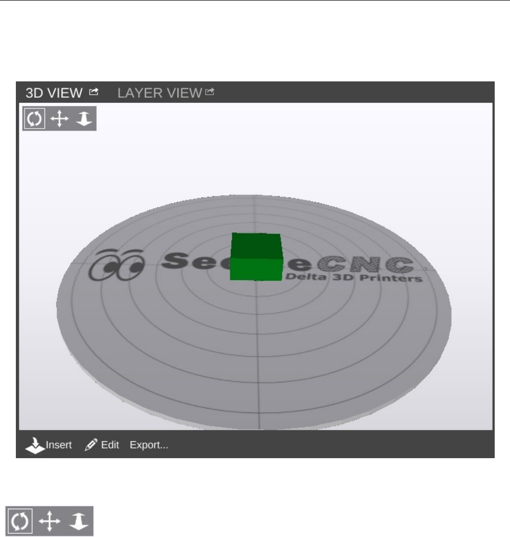
Rostock MAX v2 User's Guide
11 – Using the 3D and Layer Views
Using the 3D View and Layer View
The 3D View will show you the part that will be printed when you hit the Print button. The
Layer View is used to inspect how your part will be printed, one layer at a time.
The 3D View will allow you to view your model in pretty much any orientation you'd like. The
view orientation is controlled one of two ways. You can select one of the movement icons
in conjunction with the left mouse button. The first icon will allow you to “free
rotate” the model and build platform. The second icon will allow you to move the
part and build platform left and right, as well as up and down. The third icon will allow you to zoom in
and out.
11 – Using the 3D and Layer Views - 88
The 3D View.
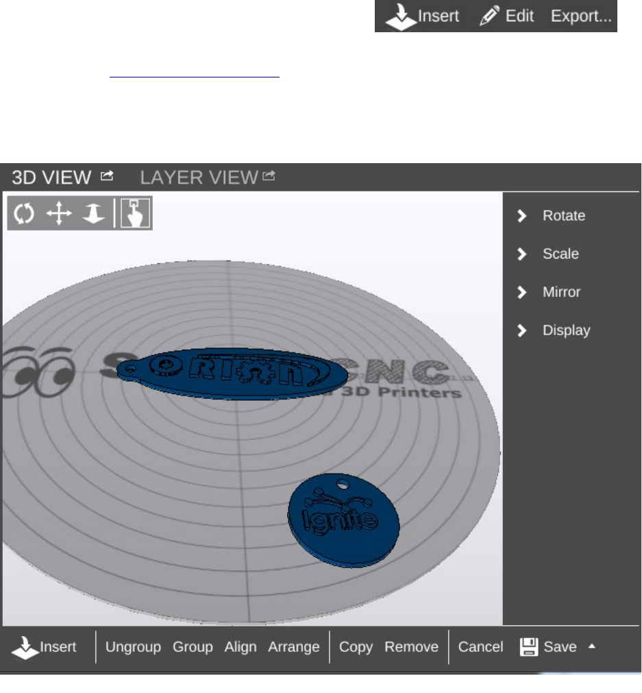
Rostock MAX v2 User's Guide
You can use the mouse by-itself as well. Holding down the left mouse button will allow you to
“free rotate” the model and bed. Holding down the mouse wheel will allow you to move left and right
as well as up and down. Spinning the mouse wheel will zoom in and out.
The 3D View will also allow you to directly manipulate the part or parts currently being
displayed on the virtual print bed. The first control, Insert
is used to add one or more components to the virtual print
bed. To give you an idea of how this works in practice, head over to Repables and grab the “Ignite
Michiana” object – http://repables.com/r/146/.
MatterControl is pretty smart – you don't have to extract the STL file from the ZIP file. Click on
Insert and navigate to where you saved the downloaded zip file and select it. When the file is loaded,
your screen should look something like this:
11 – Using the 3D and Layer Views - 89
Auto-arranging parts.
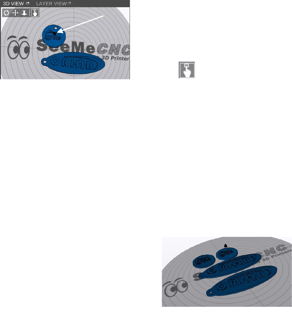
Rostock MAX v2 User's Guide
If you didn't already have the example cube loaded, you may only see one object in the center
of the bed. If this is the case, go ahead and load another Ignite object. If you can't see the object
you've just loaded, click the Arrange button to automatically move the objects to the virtual bed.
You'll end up with something similar to the figure below after clicking on Arrange.
The white arrow points to a tiny icon that indicates which
is the currently selected object. If you tilt the platform
(right-click and drag your mouse), you can see that the icon
is actually a tiny cone or arrow.
In order to move an object around manually, you'll need to
make sure that the “picker” icon has been selected.
Once you've clicked on that icon, you'll be able to move
the parts any where you like. However, be aware that the
software will allow you to move the objects outside the
confines of the virtual bed and they will not be printable outside of those limits.
You'll notice that you've got some new controls along the bottom of the 3D View window –
Ungroup, Group, Align, Arrange, Copy, Remove, Cancel, and Save.
The Ungroup button will undo the “grouping” done by the Group and Align buttons.
Clicking Group will virtually connect all the objects on the print bed so they can be moved all
at the same time.
The Align button has the same effect as the Auto-Arrange button, but the resulting group of
objects are not centered on the virtual print bed.
Arrange will auto-arrange the parts in a grid pattern.
Copy allows you to create duplicates of objects that are on the print bed as shown below. Make
sure that you've got the object you want to copy selected before you click the Copy button.
Be aware that if you've got your objects
grouped, clicking on Copy will result in the entire
group being copied.
The Remove button works as you'd expect.
Select an object and click Remove to remove it from
the virtual build surface.
11 – Using the 3D and Layer Views - 90
Object selected.
Copied objects.
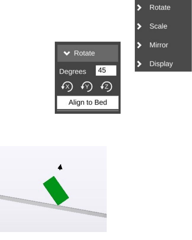
Rostock MAX v2 User's Guide
Cancel will discard any changes you've made so far and Save will allow you to save the state of
the virtual print surface. Saving your work saves it to the print queue. If you'd like to save your work
as a combined STL file
While you're in edit mode, there's a series of commands that become
available along the right edge of the 3D View pane.
Unlike normal manual positioning, the Rotate function allows you to
specify the exact rotation of the object along its X,
Y, and Z axes.
In order to change the orientation of the
object, simply enter the value you want in the
Degrees field and then click the axis you want to
apply that value to. Below is an example of what
the example cube looks like after rotating it 45
degrees along its X axis.
Being able to re-orient the part on the build surface can be handy to have, especially if you're
dealing with a part that was saved in a position that didn't lend itself to easy 3D printing.
Clicking Align to Bed will automatically orient the nearest flat surface to the virtual build
platform.
11 – Using the 3D and Layer Views - 91
Tilted object.
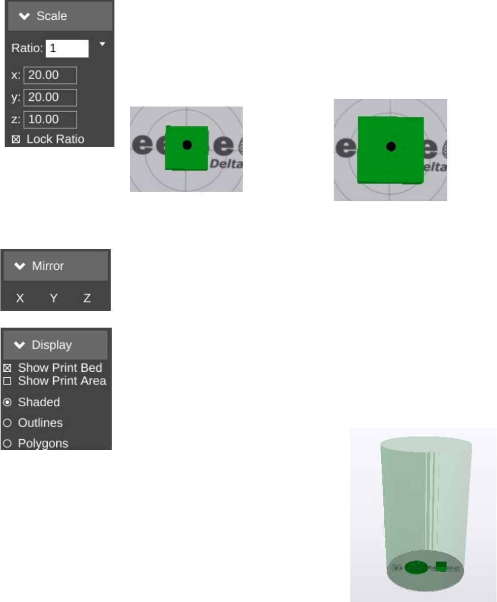
Rostock MAX v2 User's Guide
The Scale function will allow you to change the width, height and length
of the part or parts currently on the virtual build platform.
The Ratio field allows you to shrink or grow an entire model by a
specific percentage. For example, if you were to change the Ratio from 1 to
1.5, you'd see this:
Become this:
The scaling operation made the cube 150% larger than the original. The X, Y, and Z fields
allow you to specify exact dimensions. However, as long as the Lock Ratio field is checked, any
change made to those fields will adjust the others to maintain the same ratio.
The Mirror function will simply allow you to “mirror” the object along
any of the three axes. Note that mirroring the Z axis will flip the part upside
down, so be careful.
The Display function allows you to modify how the 3D View pane
operates. Show Print Bed is pretty obvious. Uncheck it and see what happens!
Shop Print Area is handy when you want to see exactly how much space your
parts are going to take up. When selected, it will display a shadowed cylinder
that encapsulates the maximum bed diameter and print height, as show below.
The Shaded, Outlines, and Polygons options allow you to
change how your objects are drawn. By default the Shaded option is
checked. For most parts this is fine, but if you'd like to see detail that
the solid shading can hide, click Outlines. Models used for 3D
printing are built out of a few up to many thousands of polygons. If
you'd like to see what the polygons look like that make up your model,
click the Polygons option.
11 – Using the 3D and Layer Views - 92
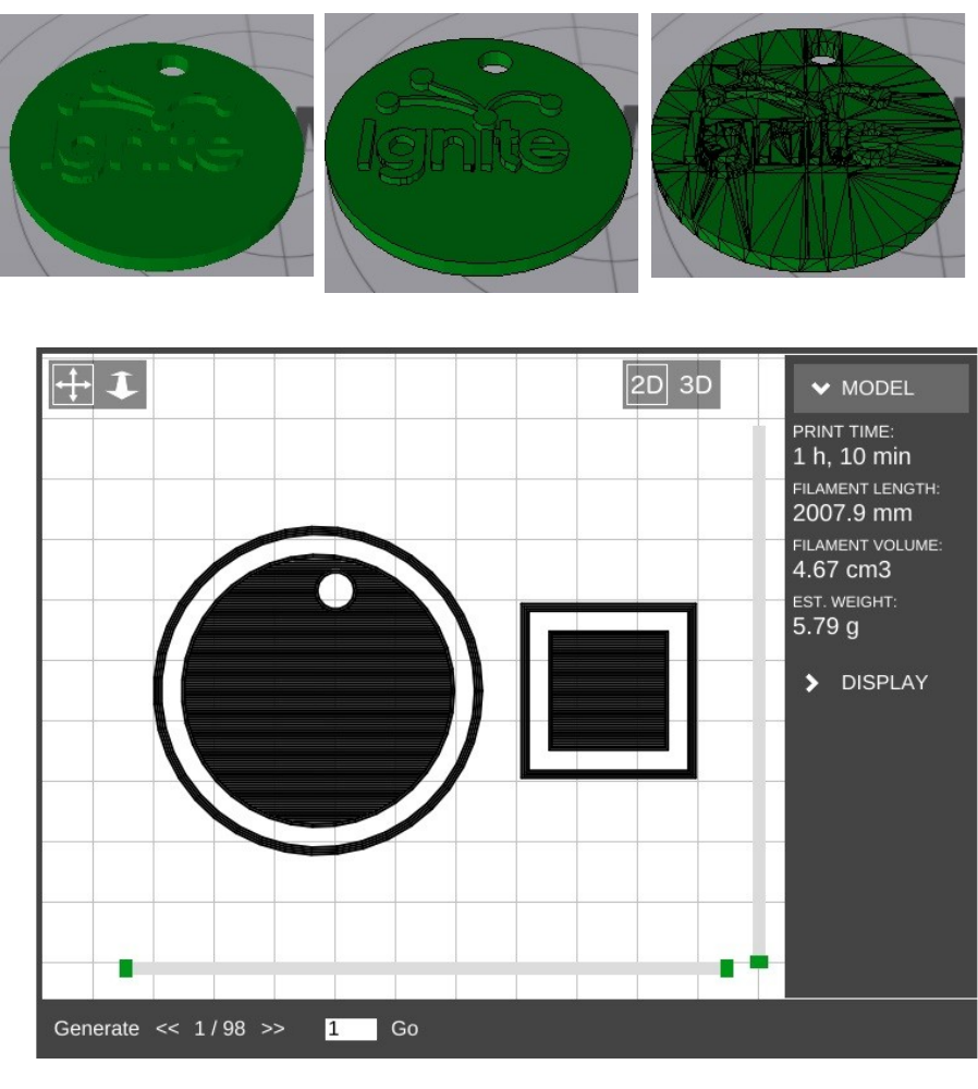
Rostock MAX v2 User's Guide
I find that the Outlines display option is the most useful as it makes part details really stand out.
The Layer View is where you can see exactly what the Rostock MAX is going to do while
printing your part. When you first select it, it may show “Press 'generate' to view layers”. Click the
Generate button in the lower left corner of the Layer View display.
11 – Using the 3D and Layer Views - 93
Shaded Outlines Polygons
The Layer view.
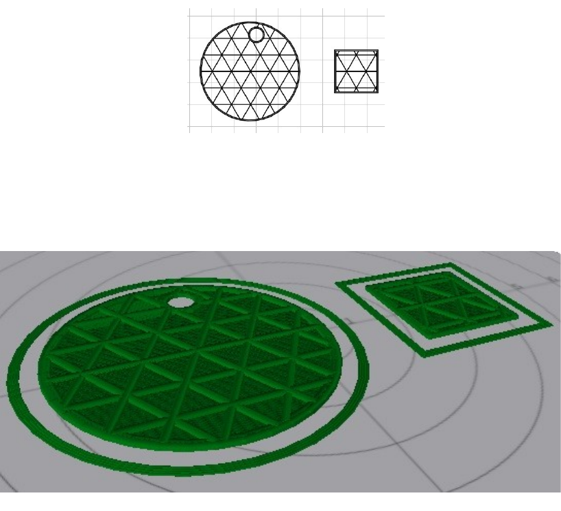
Rostock MAX v2 User's Guide
This will hand over the parts to the slicing engine and will create the G-Code required to print
your parts. In the image above, you can see that the parts have been sliced and layer #1 is being
displayed.
Along the right side of the display, you'll see a printing time estimate as well as an estimate of
how much filament will be required to print the two parts shown.
There are two “scroll” bars shown in the Layer View. The bar along the bottom will show
progress of the current layer, while the vertical bar will show layers. Using the << and >> buttons
along the bottom, you can step through the layers one at a time, or jump to a specific layer and click on
the Go button.
The Layer View will also allow you to see the layers in 3D. Just click the 3D icon at the upper
right corner of the display window to see your layers in 3D! The display can be moved around in the
same manner as that shown for the 3D View.
The Layer View will also display other information about the printing process, such as non-
printing movement, retractions, etc. Click on the Display button to the right of the display to open up
those display options.
11 – Using the 3D and Layer Views - 94
7 Layers in.
7 Layers in, 3D view.
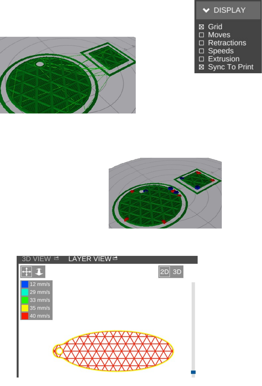
Rostock MAX v2 User's Guide
Grid hides or displays the virtual print surface.
Moves will show you the path the print head takes when it's not printing,
as shown by the light green lines in the image below.
Retractions show the points in the print where the extruder is going to retract filament from the
hot end. This is done either during a non-printing move, or when changing extruders.
The red and blue points in the image to the
right show where the retractions are happening.
Red shows the retract operation while the
blue color shows the resume/extrude.
Speeds will color the layers based on how fast the layer is printed.
11 – Using the 3D and Layer Views - 95
Travel moves.
Retracts.
Layer speed.
Rostock MAX v2 User's Guide
The Extrusion option will thicken the lines used to draw the layers in order to give a more
accurate visual representation of what the actual print layer will look like when printed.
Finally, Sync to Print will allow you to follow the print process using the Layer View. As the
Rostock MAX prints your part, you'll see a real-time reflection of those moves. It's a pretty nice
feature.
11 – Using the 3D and Layer Views - 96

Rostock MAX v2 User's Guide
12 – A Strategy for Successful (and great!) Prints
Michael Hackney is one our forum moderators over at the SeeMeCNC forum and he's been
gracious enough to allow me to publish his wonderful guide for getting the most out of your
SeeMeCNC 3D printer. You can find his original thread here:
http://forum.seemecnc.com/viewtopic.php?f=36&t=7361
Some of the links below reference part files that are stored on the forum itself. You may need to
create a forum account to reach them. I highly recommend doing this whether or not you need the
files. The SeeMeCNC is an excellent resource with a vibrant, helpful and very newbie-friendly
community.
I've watched folks struggle to achieve the results they want/expect here for several years – heck,
I was one of us. Like all new endeavors, there IS a learning curve with 3D printing. This is still the
pioneering era for desktop printing and we are very fortunate to have such a great community here as
well as other resources on the web. But the challenge with all the information out there is finding it
when YOU need it and deciphering the many different opinions and practices - some of which are good
and some of which are, well, let's just say "poppycock".
There are many different means to the same end but I assert that those who figured something
workable (AND reproducible) out most likely took a disciplined approach to reach their goals rather
than the shotgun approach of trying one thing after another. So, I thought it would be helpful to
describe a method that you can use to 1) develop a reproducible approach to successfully printing the
things you want and 2) improving the quality of your prints to meet your (realistic) expectations. I'll
likely do this as a series of posts starting with this one. Don't hesitate to join in or ask questions. After
some time, I'll consolidate the posts into a single source (maybe a pin here) that will make it easy to
find.
On board? Let's go!
#1 Get Experience.
Start with the printer. This is more difficult than it seems because without experience, it is hard
to know if you have a mechanical or electrical issue, slicing issue or if something else is going on. So,
to that end, keep things simple until you have some experience. By "simple" I mean, don't print the
Eiffel Tower model to start, print a simple, reproducible and small item many, Many, MANY times
until you nail it. For me, I used the calibration cube. In retrospect, I should have picked something
much simpler (see strategy #2).
12 – A Strategy for Successful (and great!) Prints - 97
Rostock MAX v2 User's Guide
#2 Start Simple.
We have a tendency to want to jump ahead to more complicated prints, faster printing, bigger
prints, etc. There are many aspects to successful 3D printing, everything from the printer (which in
itself has a mechanical system, electronics system, hot end, extruder, heated bed, firmware), to the
slicer (and all of the parameters available to control the slicing), to the filament itself, to the actual item
being printed. With so many variables (100s, maybe 1000s of them) it is really important to pin down
as many of them as you can.
One very easy place to do this is with the model itself. Develop your experience printing the
same model over and over until you nail it. Even with a simple model, you can (and should) approach
printing it with a methodical approach from the ground up. That's the next strategy.
#3 Practice in Measures.
I play guitar and was basically self taught. When I found new music to learn, I did what many
untrained folks do and practiced the part over and over again from beginning to end. If I made a
mistake, I started over. Then, I took lessons from a trained musician. My very first lesson was worth
every penny! My instructor watched me learn a piece and then said "Practice in Measures". What he
meant by this was to learn the first measure (music is divided into small blocks of notes called
measures which are small and relatively simple). Practice it until it is perfect. Then, practice the second
measure until it's perfect. Next, combine the first and second measures until that is perfect. Continue in
this way until you've learned all the measures and combinations of them. In complex pieces, there will
be a few measures or sequences of measures where you need to put in a lot more practice.
The advantage of this approach, my instructor said, is that you are not wasting lots of time
playing measures you already know. The practice of playing from the start until you reach a difficult
spot and make a mistake is that you play, say, 30 seconds (or more) of music you already know to hit a
1 second spot you need to practice. So in a 30 minute practice session you are really only practicing
what you need to practice for 1 minute! This completely changed my approach to practicing everything
from guitar to 3D printing to machining to learning CAD, to...
How does this apply to 3D printing? Easily, start with a simple object to print and practice
nailing the first layer. Once you have that nailed, print the rest of the object. Once you have the entire
object printed successfully, change slicing parameters and start over (nail the first layer, ...). Practice in
measures.
I can't say enough about getting that first layer right, the subject of the next strategy.
12 – A Strategy for Successful (and great!) Prints - 98

Rostock MAX v2 User's Guide
#4 Nail the First Layer.
I don't believe folks spend enough time learning to print a perfect first layer reliably. If there are
defects in the first layer, they will invariably come back later to bite you – the part separating form the
build plate or a defect in the part. Trying to print a good (or great) first layer is probably one of the
most frustrating experiences for most, it is also the most critical. Here's where strategy #3 comes to
play, don't continue a print on an inferior first layer! Abort the print and start that first layer again and
again until you nail it. Why waste time on a part that will most likely fail or not be useful? Each time
you print a first layer, measure it! If you tell your slicer to print a 0.20mm first layer, then it should be
pretty darn close to 0.20mm. If it isn't, you've identified a variable that you can easily fix and nail down
(Z height). 0.20mm is not a lot and unless you have highly calibrated eyes, you can't tell the difference
between 0.20 and 0.15mm, but your printer sure can. At 0.15mm the first layer is going to squish onto
the print surface.
It may even seem like you are getting a great first layer and great sticking (which you are) but
later, you'll discover the part is nearly impossible to remove or your extruder will start making that all
too familiar TICK, TICK, TICK sound from missing steps. A perfect first layer will go down smooth
and consistently time after time.
TIP: polish the tip of your nozzle! Charred filament and scratches on the very tip of the nozzle
are dragged over the layers as it moves around. Best case these leave a visible mark on the print, worse
case they rip the first (or higher) layer off the build plate.
#5 Slow Down.
Back to my guitar lesson example... The other thing my instructor taught me in that first lesson
was to practice slowly (using a metronome) until I nailed the measure(s) at a slow tempo. Then,
gradually and consistently, increase the speed. The same applies to 3D printing, print slowly at first.
This gives you time to observe what's going on (strategy #6) and just simplifies everything. I like to
start new folks at 20 to 25mm/s print speeds. What's the hurry? If you print 10 aborted prints at 50mm/s
what have you gained (or lost)? Printing slow helps all parts of the printer, from the mechanics to the
extruder to the plastic filament coming out the nozzle, stay in balance or equilibrium. Fast movements
can highlight mechanical issues, extrusion issues, etc. But when you are first starting out, you don't
know how to identify and isolate these issues. In fact, even with all of my experience, if something
starts to go wrong, I slow down. That removes a lot of variables and gives me a chance to see what's
happening. I've identified everything from loose pulleys to a worn joint on a delta arm to separating
arms on magnetic ball joints! And, I've helped a lot of folks identify other issues simply by slowing
down.
12 – A Strategy for Successful (and great!) Prints - 99
Rostock MAX v2 User's Guide
#6 Watch What's Happening.
Especially in the early stages of learning, watch all aspects of the printer. Combined with
strategy #5 you'll start to develop an appreciation for how the slicer does its magic, how the printer
does its magic, and it is just simply fun to watch (especially a delta printer)! I highly recommend
putting a flag of some type on your extruder so you can actually watch retracts and advances and watch
the steady push of the filament. A piece of masking tape stuck to the shaft is fine or print one of the
pointer models. Watch that first layer print, that's how you'll see if there is a problem and maybe even
figure out why. For example, I noticed that the first layer wasn't sticking in the same spot on my build
plate. Turns out that I had some potato chip grease there (don't ask)! A little wipe with Isopropyl
alcohol and I was back in business. Watch what happens when the layer fan comes on. Is it coming on
too early and causing the part to peal from the print surface? Pay attention to the details of what's going
on and then...
#7 Keep Notes.
I can't stress how important it is to keep notes. I have a word processor file I add notes to as I
go. In particular, I keep a section on the filaments I use and the detailed printing parameters for them
(strategy #9). Perhaps I'm becoming forgetful in my advanced age but I don't like solving the same
problem over and over again. If I keep a note about a problem and my solution, I can usually find it
again pretty quickly. Once comment on notes, don't be afraid to purge! After a few years of doing this,
my file got quite big.
Recently I archived all of my H1 and H1-1 notes. I don't refer to them any longer so why keep
them in my working notes?
#8 Be Consistent.
A CEO friend I worked with many years ago was fond of saying "Consistency is the hobgoblin
of small minds!". I understood what he was trying to say but it has to be taken into context. When you
are first learning any new activity, it is critical to be consistent. If too many things are changing at once,
you have no idea what contributed to a good or bad result. Don't change too many things at once. In
fact, if you can isolate and change just ONE thing, you will have a much better chance of success and
understanding. This isn't always possible so lock down as many things as you can. If after a run of
successful printing you run into a problem, go back to a known good state (see #7 – you did keep notes
on what this state was didn't you?) and start there. Many times we try to change too many things in our
frustration and that almost always makes things worse. Step back and think about how to isolate the
problem areas with as few changes as possible.
12 – A Strategy for Successful (and great!) Prints - 100
Rostock MAX v2 User's Guide
#9 Know Your Filament.
This strategy is a bit lower level than the previous eight but important and often overlooked. I
see a lot of folks just assume that they should print filament X at temperature Z – for instance, print
PLA at 200°C. This might get you in the ball park but if you really want to get to consistent and
GREAT results, profile your filament. It's easy and if you write it down (see #7) you'll never second
guess how best to print that filament again. It's important to realize that higher temperatures are not
always better, they can actually lead to issues - parts that are just a little too large, parts that stick to the
bed too well and can't be removed, blobs on the print, stringing, and a host of other problems. In
general, I like to print at the lowest temperature possible for PLA and ABS. Then, as I ramp up print
speed, I also need to ramp up the hot end temp a little since the filament is not resident in the hot zone
for as much time. I suspect little details like this cause people more problems than they might
anticipate.
Here's how I profile a new filament:
•Start with a reasonable target temperature – 200°C for PLA and 225°C for ABS (one quick note,
it is ideal to have a calibrated hot end, so when I say 200°C I mean 200°C. One easy way to do
this is to make a little table with the hot end set temperature (what you see on the temp display)
and the measured temperature (with a thermocouple). Do this in 5°C increments from 160° to
240° C (or so). Keep this chart in your notes (#7) and you will always know what the actual
temperature is.)
•Now, use the manual controls of your host to extrude 50mm at 50mm/s and watch and listen.
•If the filament extrudes nicely, reduce the temperature by 5°C and wait for the temperature to
stabilize.
•Test again by extruding 50mm at 50mm/s
•Repeat until you reach a temperature where the filament does not extrude well. At 5°C to that
temperature and note this as the "low extrusion temperature" for that filament. Use this low
temperature whenever you are printing slowly (20-30mm/s). You might find some filament need
to be bumped up a bit more than 5° so don't hesitate to experiment and find that lowest reliable
extrusion temperature.
If you want to get really serious about profiling your filaments, do the melt-flow test at higher
extrusion rates – 60 mm/s, then 70mm/s, etc.
Don't forget to measure the diameter of your filament too! Not all filaments are created equally.
Measure in several locations to get a sense of variability. Most of the slicers let you enter filament
diameter and they will calculate a reasonable flow for you.
12 – A Strategy for Successful (and great!) Prints - 101
Rostock MAX v2 User's Guide
TIP: When you are starting a new print session, give the printer a little warm up exercise!
Much like an athlete warms up before a game, don't just turn the printer on and attempt to print. Turn it
on and let the hot end get up top equilibrium, let the heated bed get up top temperature. I even like to
print a quick part (a 20mm diameter cylinder 5 mm tall) to make sure everything is up to temp, in
equilibrium and working properly. It's quick and easy to do and can help eliminate a lot of problems.
#10 Know Your Bedfellows.
Probably one of the greatest mysteries in 3D printing is "the bed". Metaphorically, this is where
the rubber (filament) meets the road (bed) and getting "it" right is absolutely critical to successful fused
filament 3D printing. All sorts of folklore on bed materials, coatings, coverings, concoctions, and juju
exists here and elsewhere on the internet. It is also one of the areas that there is no one right way to do
it. If you have discovered a special incantation and bed preparation that works, by all means stick with
it! But, for those of you struggling, here are some strategies you can use to make improvements. One
comment before I begin...
I am VERY persnickety about the aesthetics of my 3D prints. My 3D printed fly fishing reel is
seen from all sides and so it is important that the first layer is flawless and visually appealing. A perfect
first layer finish is not required for all objects - consider the base of a Yoda or vase - but if you practice
getting a great first layer on these non-critical pieces you'll be prepared when you need a visually
perfect first layer on another project.
A number of factors affect adherence of the first printed layer to the bed. These include:
•surface material
•surface texture
•surface treatment/coating
•bed temperature and uniformity of temperature
•air temperature
•chemical bonding or cohesion
•print speed (see #5)
•filament temperature (see #9)
•first layer height (see #4)
•cleanliness (of bed and filament)
This isn't an exhaustive list but it does include the big hitters and, as you can see, there are a
few of them so it is very important to take a methodical (#2 and #8) and documented (#7) approach
when solving bed-related problems. This is also a place where careful observation (#6) can play an
important part.
12 – A Strategy for Successful (and great!) Prints - 102
Rostock MAX v2 User's Guide
I'm not going to go through all of these in detail now but did want to comment about the last
one - cleanliness. Whatever you do, make sure everything near and on your printer is clean and grease
free. Silicone greases and lubricants are especially problematic since they are invisible and very
difficult to remove. Keep them away from your machine.
Your fingers are a prime source of contaminants. Every time you touch the filament or bed, you
risk leaving a greasy print (see my observation in #6) and these can (and will) cause issues. I try not to
handle filament with my bare fingers, I use cotton gloves. If you use a plastic or rubber glove, make
sure it isn't coated or powdered - we're trying to eliminate sources of contamination, not introduce
them. On the occasions that I do handle filament with my bare hands I wash and dry them thoroughly
first. This is one area that I think affects a lot of user's and is completely overlooked. How many times
have you loaded filament right after eating chips? It introduces a big variable that can be difficult to
track down, so develop good habits and eliminate contamination as a variable.
Your fingers can also leave contaminants on the bed when you remove a part or brush off stray
filament strands. Don't touch the bed surface if at all possible. If you do, clean/degrease it with an
appropriate cleaner. For uncoated surfaces like borosilicate glass, PEI, the various 3d party surfaces
(PrintInZ and BuildTak), and films (window tint, Kapton) you can use Isopropyl alcohol. I like to use
the little packages of wipes as they are convenient and safe. You can also do a quick wipe of your
fingers before tossing it in the trash. It is more difficult to deal with coatings like PVA glue, glue stick,
and hairspray since these can't be cleaned. If you suspect a contaminated coating, your only recourse is
to remove and reapply it.
Finally, don't overlook filament storage, keep it clean too. I store mine in large zip lock bags to keep off
dust. You can put packets of desiccant to help remove moisture in the bag too.
#11 Learn to Diagnose.
Patient: "Dr. it hurts when I move my arm like this."
Dr.: "Then don't move your arm like that!"
The first point of this joke is, many people do the same thing over and over again without
making any changes or stopping to think about what to change (see #8: remember, change one thing at
a time) - as if just repeating the same print with the same parameters will magically solve the problem.
It won't (see my footnote below).
12 – A Strategy for Successful (and great!) Prints - 103

Rostock MAX v2 User's Guide
The second point of the joke is that the Dr. didn't attempt to actually determine why the patient's
arm hurt, he just had him avoid the problem. I see that a lot too. Usually it takes to form of "I tried
printing it with my red PLA and it failed but everything was fine with my blue PLA". There are
many other variations on this (changing slicers for example).
Learn how to diagnose problems. This requires careful observation (#6). Once you've identified
where the problem occurs (let's say getting the first layer to stick) then PRACTICE that piece (see #3)
until you sort it out. No need to run through the entire process over and over. Isolate the problem,
formulate a hypothesis on what you think might be happening and design a test to prove or disprove
your hypothesis. If you see a problem and can't formulate a hypothesis THEN seek help! Or, pre-test
your hypothesis here to get some experienced feedback. But, whatever you do, try to work through the
diagnostic process yourself first, that's how you learn.
Footnote: Many years ago (20) my company had an annual laboratory safety week (I worked in
a corporate R&D lab with lots of nasty stuff). One of the annual favorites was a gentleman from OSHA
who talked about electrical safety. He started his presentation with a black and white video from the
1940s (I think) of a speaker walking up to a microphone on stage. The presentation was being filmed.
The speaker reached up and grabbed the mic and was immediately thrown back and fell to the stage
unconscious. Members of the audience rushed up to help him. This was all on video. As 4 or 5 people
worked to help the victim, you see a gentleman casually walk up to the mic, reach out his hand and
touch the mic. He was immediately thrown back and collapsed on the stage next to victim #1. Literally
30 seconds later a THIRD audience member walked up to the mic (now there are 2 victims on the stage
and a hoard of people working to revive them) and carefully reached out his finger (looked like the
scene from ET) and very, very gently touched the mic with just the tip of his finger. He was
immediately thrown to the stage as the third victim. All of this was caught on video. No one died (we
were told). Neither of the second two victims stopped to think about the problem, consequences or
solutions.
12 – A Strategy for Successful (and great!) Prints - 104
Rostock MAX v2 User's Guide
#12 Be a Fanboy.
I am probably going to lose some fans for this post about cooling fans!
Don't think of a part cooling fan as an object. Instead, think about "air flow". If you need
cooling on a PLA (or other material) part, then you need to understand air flow. Not all cooling fans are
created equally. Consider this, some folks use a 40mm, some a 25mm, some (like me) a 25mm squirrel
cage fan. Some are mounted to blow the full fan width stream at the nozzle area, some have a duct or
some (like mine) have a very focused soda straw duct). So comments like "run your fan at 1/2 speed"
are not specific enough to be useful information. Instead, you need to understand how your particular
fan, it's arrangement, your material, etc, all relate to the air flow.
Firstly, using the previous strategies, try to minimize or eliminate the need for any sort of air
cooling. Slowing a print down (#5) is one great way to do this. It also gives you a chance to see (#6)
where any problem areas on a print might be. You can use this information to focus the right amount of
air flow on the problematic areas. The tendency for many is to use as much air as possible. It is much
better, more consistent, and more reliable to use as little air flow as necessary. This puts less thermal
stress on the printed part.
When you do determine you have a problem that only a fan can solve, start conservatively. I
also seriously recommend using a duct of some sort to focus the air flow where you need it. Ideally, the
fan would have the ability to follow the print nozzle and direct a small stream of air to the filament
right after it is laid down. That is a difficult problem to solve, so most of us direct the air to area around
and under the nozzle. But, by directing the air (duct) you can reduce the air flow significantly since it is
now focused where you need it. Here is an example of some of my fan research. The part on the left
failed (in a previous run) as you can see due to warping caused by an uneducated 25mm inducted fan
blowing at 50%. The part being printed on the right was my first attempt at using flexible soda straws
(2 of them) to direct the air flow to exactly where I needed it. I also ran the fan at 20%
12 – A Strategy for Successful (and great!) Prints - 105
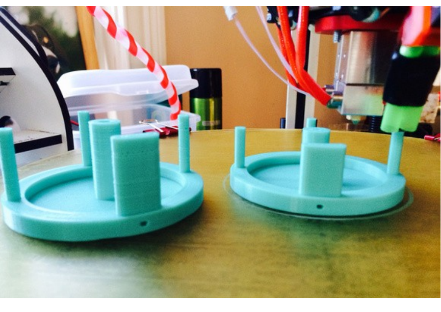
Rostock MAX v2 User's Guide
The angle of the photo doesn't show it clearly but the "double barrels" are focused at the tip of
the nozzle. The "dead air" space between the tubes prevents air from flowing over the nozzle. I know,
it's terribly clever! It's a work in progress and I've almost got it perfected with a printed double barrel
nozzle.
I suggest doing your own experiments and observations but start conservatively. I don't use a
fan during the entire part. If you find you need to turn the fan on at full blast from no air flow, do it in
stages so the hot end can equilibrate properly. You can do this manually, some slicers can support it, or
it is easy enough to learn the simple "fan mcodes" to manually insert them where you need them in the
gcode file (this is what I do for tricky parts).
M107 is fan off
M106 S50 turns the fan on at 50% - the S parameter is the speed from 0 to 100
Using a focused air flow, lower air flow and the step up technique I just described, you won't
see a significant drop in hot end temperature and you won't see a tell tale sign on the part that the user
'Polygonhell' mentions. PLA has this interesting property that if you change the extrusion temp at the
hot end, it has a visible effect on surface sheen of the part from matte to gloss as you raise the
temperature.
12 – A Strategy for Successful (and great!) Prints - 106
Fishing Reel parts.

Rostock MAX v2 User's Guide
RichRap has written an excellent post about how he uses this phenomenon when printing
decorative vases. Although he was varying the hot end temperature, a similar effect can occur with
improper air cooling.
I'm also an advocate of using off-platform cooling. By this I mean strategically placed (ducted)
fans that direct air to problematic areas of a print. These can be mounted to your vertical columns or
simply sat on the bed if it is not too hot. With ducting, you can reduce the air flow considerably and
keep the cooling right on a "hot spot". This technique does require manual adjustment, repositioning,
etc. But, it you are trying to print a really tricky part, it might be the only way to do it. Frankly, the part
cooling capabilities of desktop 3D printers is extremely primitive at this point. It's fine for the majority
of objects you might print but as we push the envelope on what's possible, part cooling is one area that
needs some more work to automate it.
Consider this, the way I maintain very tight tolerances on the rotating spindle and hub
assemblies on my fly fishing reels is to use a low beam of air cooling on the spindle as it's printed. This
"locks" the filament in place in a very predictable way. Once I printed a few parts and measured them
to make sure there was little variation, I incorporated that into the design to get exactly the tolerance
these parts required.
Calibration things:
This first set is a 20mm diameter cylinder, 0.6mm tall. There are 3 variations and the all width
is the first part pf the STL file name. Start with the pt4mmx20mm-cylinder.stl if you have 0.4mm
nozzle orifice. You can use these to:
1) get first layer adhesion to the bed
2) first layer thickness (stop the print after first layer and measure it)
3) total print height (should be about .6mm)
4) X-Y calibration (should be 20mm diameter)
5) eliminate blobbing and other surface artifacts - follow the guide above, print slow, adjust
retracts, etc. KEEP NOTES!
pt3mmx20mm-cylinder.stl
http://forum.seemecnc.com/download/file.php?id=8207
pt4mmx20mm-cylinder.stl
http://forum.seemecnc.com/download/file.php?id=8208
12 – A Strategy for Successful (and great!) Prints - 107

Rostock MAX v2 User's Guide
pt5mmx20mm-cylinder.stl
http://forum.seemecnc.com/download/file.php?id=8209
pt6mmx20mm-cylinder.stl
http://forum.seemecnc.com/download/file.php?id=8210
Highcooley's Onyx Bed Leveling Aid is a great one to test your calibration. Highly
recommended. If you can print it perfectly you've "arrived". I couldn't find a similar thing for the
Orion. If you know of one, let me know and I'll add it.
texsc98 took the challenge and created a parametric version that has defaults for Orion.
Layer Tuning
You can use this set of files in a number of ways - everything from testing calibration results to
exploring slicer options to breaking in a new filament. These are designed for a .2mm layer height.
The first cylinder (pt2mm tall) I call the Simple Single Layer Test and is my workhorse
calibration object for tuning first layer adhesion issues, profiling new filaments and host of other uses.
It is one layer high and can be used to test adhesion to the bed and first layer thickness (measure it with
a micrometer or calipers and compare to what the first layer height was supposed to be). You can use
this to tune your printer and slicing parameters to get perfect infill and explore the effects of speed on
infill quality without wasting a lot of time and filament printing larger parts poorly. I also use it when I
am testing a new filament to dial it in. It's a really versatile tool and I use it every day.
75mmDisk-pt2mmtall.stl
http://forum.seemecnc.com/download/file.php?id=8475
This cylinder is 0.4mm tall, or two layers. It can also be used similar to the first cylinder but the
second layer will show issues in orthogonal movements to the first layer. It also provides a little more
thickness to measure to verify layer height. It can also help tune the top capping layer.
75mmDisk-pt4mmtall.stl
http://forum.seemecnc.com/download/file.php?id=8476
The last cylinder is 0.6mm tall, or three layers. Again, it can be used like the first two. I don't
use it as often.
75mmDisk-pt6mmtall.stl
12 – A Strategy for Successful (and great!) Prints - 108


Rostock MAX v2 User's Guide
Appendix A: Maintenance and Troubleshooting
Like any machine, your Rostock MAX 3D printer needs preventative maintenance to continue
to function as good as the day you built it. Vibration and heating/cooling cycles can take their toll and
you want to stay ahead of any issues before they begin to adversely affect your prints.
1. Check the condition of your drive belts to insure they’re not getting worn out or rubbing on
any of the Rostock MAX v2 structure. Check to make sure that a print too close to the bed
hasn’t caused the drive gear to chew up the belt in one spot. This would be a good item to
add to your start-up checklist.
2. Check all bolted connections to ensure that vibration hasn’t begun to loosen them. This
should be part of your start-up checklist.
3. Make sure that the fan in the power supply remains dust-free. Vacuum it out periodically to
prevent the buildup of too much dust. Dust traps heat and isn’t any good for power
supplies.
4. Keep the RAMBo free of dust. Clean it periodically with either canned air or a dry
paintbrush. Do NOT use a vacuum cleaner on it! The tip of a vacuum cleaner accumulates
static electricity and will kill the RAMBo dead as a post.
5. Keep the heated bed free of scratches and debris. If your bed gets too scratched up to be
usable, you can either order a new one from SeeMeCNC or go to your local glass shop and
order a 300mm diameter disc of glass, 1/8” to 3mm thick. Compare the thickness of the
glass and your original build surface. If the glass isn’t the same, you may need to re-adjust
your Z axis height.
The problem with troubleshooting is sometimes trouble shoots back. :)
Your Rostock MAX v2 3D printer is a pretty complex piece of machinery even though it looks
pretty simple. As with any complex device sometimes things can go wrong in really weird ways. This
won’t be a comprehensive troubleshooting guide, but will touch on a few of the problems I’ve run into
with my printer. As others offer tips, they’ll be added to this section.
Appendix A: Maintenance and Troubleshooting - 110
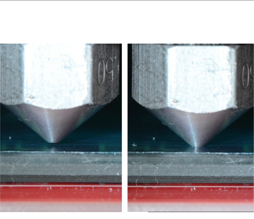
Rostock MAX v2 User's Guide
Print Layer Issues
When you first start a print, you should get a very even and consistent layer height. By properly
adjusting the machine, you should get this automatically if you’ve got all three towers adjusted exactly
the same. Unfortunately, that’s really difficult to do. The larger the object you print, the more obvious
first layer thickness inconsistencies will be, especially when using loops.
Above is an example of correct and incorrect nozzle height. The nozzle on the right is right at
the surface of the print bed. This means that there’s no room for the plastic to go – the bed is effectively
plugging the nozzle and will eventually cause the extruder to start skipping, or it'll grind a notch in the
filament as it tries to feed it.
Appendix A: Maintenance and Troubleshooting - 111
Nozzle height examples. (Image Courtesy of LulzBot)
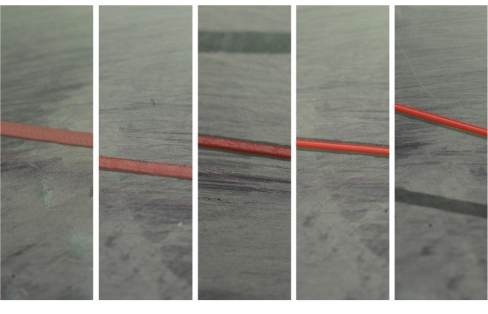
Rostock MAX v2 User's Guide
In the figure above, you’ll see five different print examples. On the far left you see the result of
the nozzle being too close to the print bed, while at the far right you see the result of the nozzle being
too far away. The result you’re looking for is shown in the center. That’s what a good first layer should
look like. If you set the Z height such that you can just begin to feel a sheet of note paper begin to drag
between the nozzle and machine bed, you’re pretty close to the ideal Z height when at zero.
Appendix A: Maintenance and Troubleshooting - 112
First print layer examples. (Image Courtesy of LulzBot)
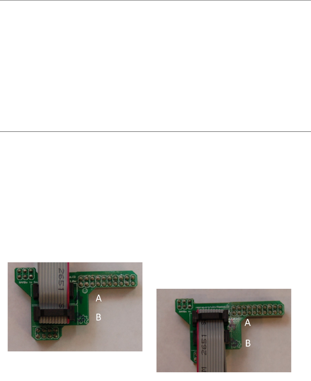
Rostock MAX v2 User's Guide
Machine Won't Move!
You’ve sent G28 and the machine still won’t move using the jog buttons. Take a look at the
serial terminal output. You may be seeing an error go by that looks like this:
Extruder switched off. MINTEMP triggered!
What is most likely happening is that you haven’t yet plugged the hot-end thermistor in. The
firmware is preventing the machine from moving because of this – it’s a safety measure of sorts. A cold
thermistor will read ambient room temperature, but a failed one may not – it could read zero or some
very high number. The firmware is will prevent the Rostock MAX from operating if the thermistor
readings are below 3 degrees Celsius for the hot end and heated bed, or if the hot end temp is above
275 or the heated bed is above 140. (These are defaults and shouldn’t be messed with unless you know
exactly what you’re doing)
LCD Panel Not Working
The LCD interface in the Rostock MAX v2 is a pretty simple device – there's not a whole lot
that can go wrong with it. The most common issues involve either the display not lighting up or the
knob not properly operating. Both of these issues boil down to a wiring issue. Remember, before
working on your Rostock MAX v2, make sure you turn off the power!
First, check to make sure that the small interface PCB is properly installed on the RAMBo. It's
pretty easy to get it on there shifted to the left or right by one pin. (Rare, but it can happen.)
Next, you need to make sure you've got the cabling between the LCD and the interface board
installed properly.
If you've got an LCD controller that has a white PCB, you'll need to make sure that the red
stripe on the ribbon cables are on the right side as shown below.
If you've got an LCD with a red or blue PCB, then
the red stripe should be on the left side.
Appendix A: Maintenance and Troubleshooting - 113
Cabling for white PCB.
Cabling for red or blue PCB.
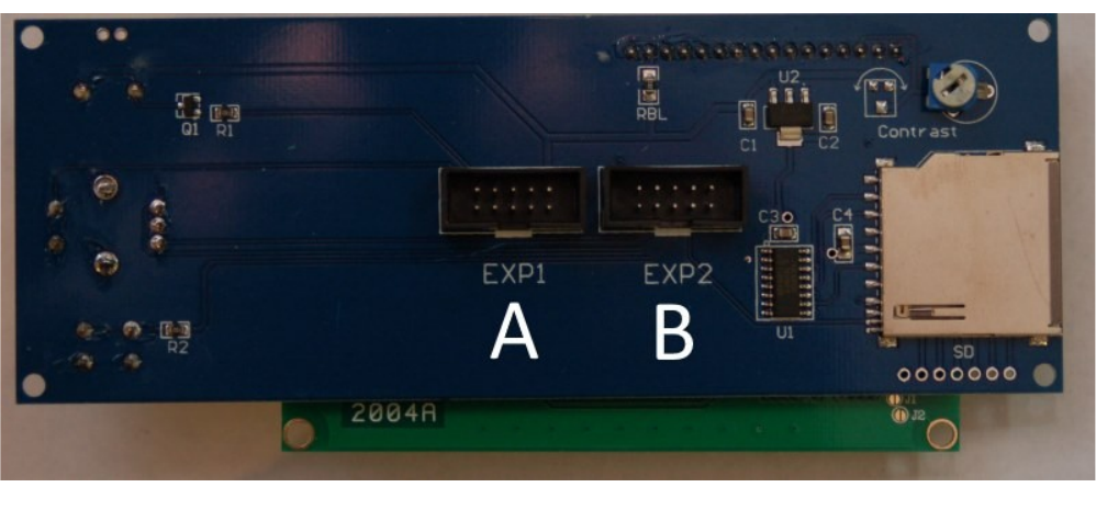
Rostock MAX v2 User's Guide
You should also make sure that the cabling from the LCD to the small PCB goes to the correct
connectors.
Make sure that your “A” and “B” ribbon cables match the locations shown on the prior page as
well as those shown below.
If your LCD still isn't operating properly after you've verified the ribbon cable is oriented and
installed properly and the LCD interface board is properly installed, start over! Remove the ribbon
cables from the LCD, remove the adapter from the RAMBo and the ribbon cables off the adapter.
Carefully re-install the ribbon cables and the RAMBo adapter and see if things work. The idea here is
to ensure that your problem isn't caused by a loose connection.
Appendix A: Maintenance and Troubleshooting - 114
"A" and "B" ribbon cable positions.
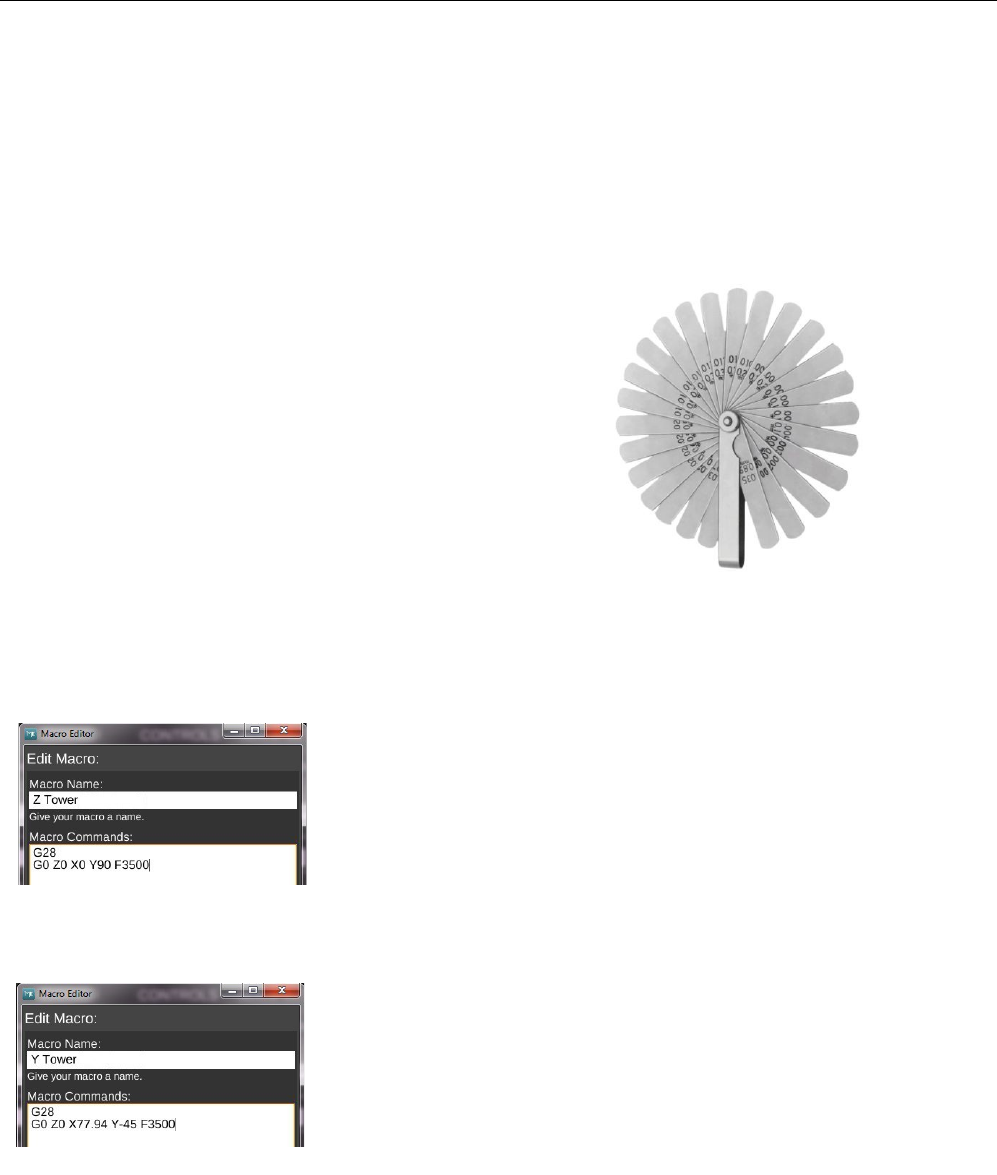
Rostock MAX v2 User's Guide
Appendix B: Alternate Calibration Method
The calibration method I'm going to outline here was originally used in the 2nd Edition of the
Rostock MAX v2 Assembly Manual. With the introduction of the 3rd Edition, it was requested that I
utilize the same calibration process that the fine folks at SeeMeCNC use when calibrating the Orion
printers after they're built. Both methods achieve the same result and I'm merely including this
alternate method for those that are interested in using it.
Note that unlike the original process that used a sheet of notebook paper, I want you to use a
0.009” feeler gauge. The photo below is the style you want to get:
Note that if you get a set that doesn't include the
0.009” gauge, you can use one similar in thickness.
It may be easier to use if you remove the feeler
gauge leaf from the set and rub the oil off of it – you don't
want the protective oil from contaminating the glass bed.
It will “re-oil” itself once it's replaced in the pack of gauge
leaves.
The first thing you'll do is create four new macros within MatterControl.
Create and name macro #1 “Z Tower” and use the following G-Code:
G28
G0 Z0 X0 Y90 F3500
Create and name macro #2, “Y Tower” and use the following G-Code:
G28
G0 Z0 X77.94 Y-45 F3500
Appendix B: Alternate Calibration Method - 115
Fig. A-1:Typical feeler gauges.
Fig. A-2: Z Tower.
Fig. A-3: Y Tower.
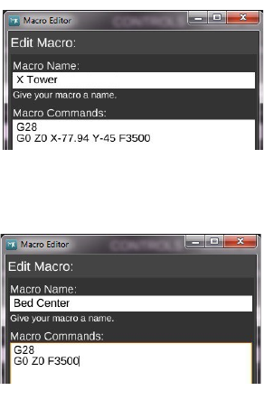
Rostock MAX v2 User's Guide
Create and name macro #3, “X Tower” and use the following G-Code:
G28
G0 Z0 X-77.94 Y-45 F3500
Create and name macro #4, “Bed Center” and use the following G-Code
G28
G0 Z0 F3500
In order to make sure that each axis is higher than the destinations of the four macros you just
created, I want you to position the machine using the terminal window. Enter these commands using
the G-Code Terminal:
G28
G0 Z5 X0 Y90 F3500
Perform the same check on the other axes by issuing G28 followed by G0 Z5 X77.94 Y-45
F3500 and G0 Z5 X-77.94 Y-45 F3500. You're not after accuracy at this point, you just want to get the
nozzle from smashing into the build plate.
Once you're confident you can go to the heated bed without striking it, you can begin to
precisely adjust the end stop screws.
Click the “Z Tower” macro button. This will send the g-code you entered previously to the
Rostock MAX. Make sure you've got your feeler gauge under where the hot end will “land”. Having
these in macro form makes the repeating task of setting the end stops much easier.
Your goal here is to have the nozzle touching the feeler gauge just enough that you can feel the
additional friction of the feeler gauge “dragging” under the nozzle. You want that same amount of
“grab” to be equal among all your test locations.
You adjust the height of each axis by turning the end stop adjustment screw to the right to raise
the platform and to the left to lower the platform. Each time you make an adjustment, click the “Z
Tower” macro button. Repeat this process until you're getting the same amount of “grab”
on the paper as you did when setting the initial Z height. When you're satisfied, move on to the “Y
Tower” and “X Tower” macros.
Appendix B: Alternate Calibration Method - 116
Fig. A-4: X Tower.
Fig. A-5: Bed Center.
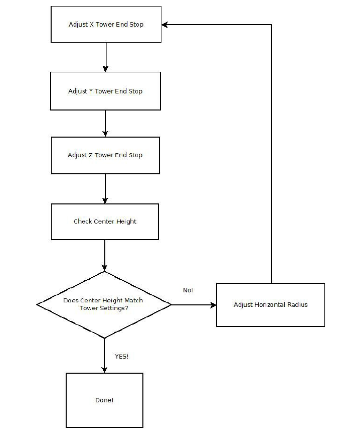
Rostock MAX v2 User's Guide
Set your feeler gauge on the center of the build platform and click on the “Bed Center” macro
button. The nozzle tip is going to end up in one of three positions. It's going to be above your feeler
gauge a visible amount, it's going to pin the gauge firmly to the bed, or if you're incredibly lucky, it will
be “gripping” the feeler gauge the same amount as the tower base calibration steps. If it IS, I strongly
recommend you go buy a lottery ticket. Your luck is just that good. (If you win, I want a cut!)
Appendix B: Alternate Calibration Method - 117
Fig. A-6: Calibration Flowchart.
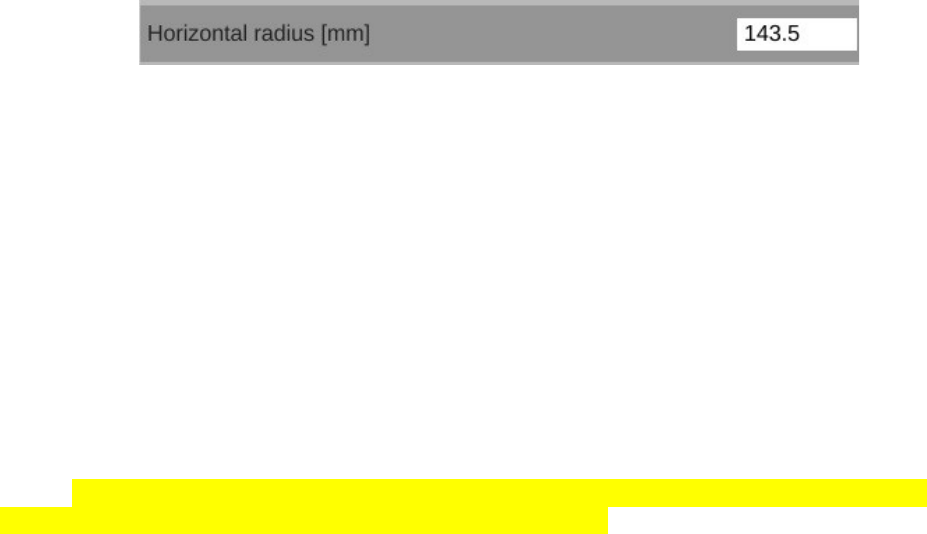
Rostock MAX v2 User's Guide
If you're a mere mortal like the rest of us poor suckers, you're going to have to make an
additional adjustment. Delta configuration printers like the Rostock MAX v2 have a very interesting
geometry that will result in the hot end traveling in a non-flat path if it's not perfectly calibrated. This
tiny error will express itself as a “virtual” convexity or concavity in what it thinks the bed shape is. If
your hot end is pinning the feeler gauge to the build surface, the error is expressing itself as a concavity
– the firmware thinks that it is moving flat, but the path of the hot end is actually concave and that's
why it pins the feeler gauge to the build surface – the center is actually lower than it should be. The
reverse is also true – if the hot end is not touching the paper at all, it thinks that the bed is dome shaped
(convex). This all boils down to what happens when the “perfection” of mathematics runs face-first
into the “imperfection” of reality. :)
The concave/convex shape of the bed is controlled by the EEPROM table entry labeled
“Horizontal radius [mm]”.
What you're going to do is change that figure by 0.5 until the nozzle is touching the paper just
the same as it was when you calibrated at the base of each tower.
In order to lower the nozzle, you'll need to increase the Horizontal Radius value.
In order to raise the nozzle, you'll need to decrease the Horizontal Radius value.
Each time you change the Horizontal Radius, you must re-calibrate the base of each tower as
you did in the previous steps using all four macros in the Z, Y, X, Bed Center order.. It may take a
number of iterations to get the center nozzle height nailed down, but it IS worth the hassle. Your first
layer quality and plastic adhesion require that the nozzle track across the entire bed as perfectly flat as
it can.
Please make sure you click the Save To EEPROM button each time you make a change,
otherwise the new Horizontal Radius value will not take effect!
That's all there is to it!
Appendix B: Alternate Calibration Method - 118
Fig. A-7:Horizontal Radius value.
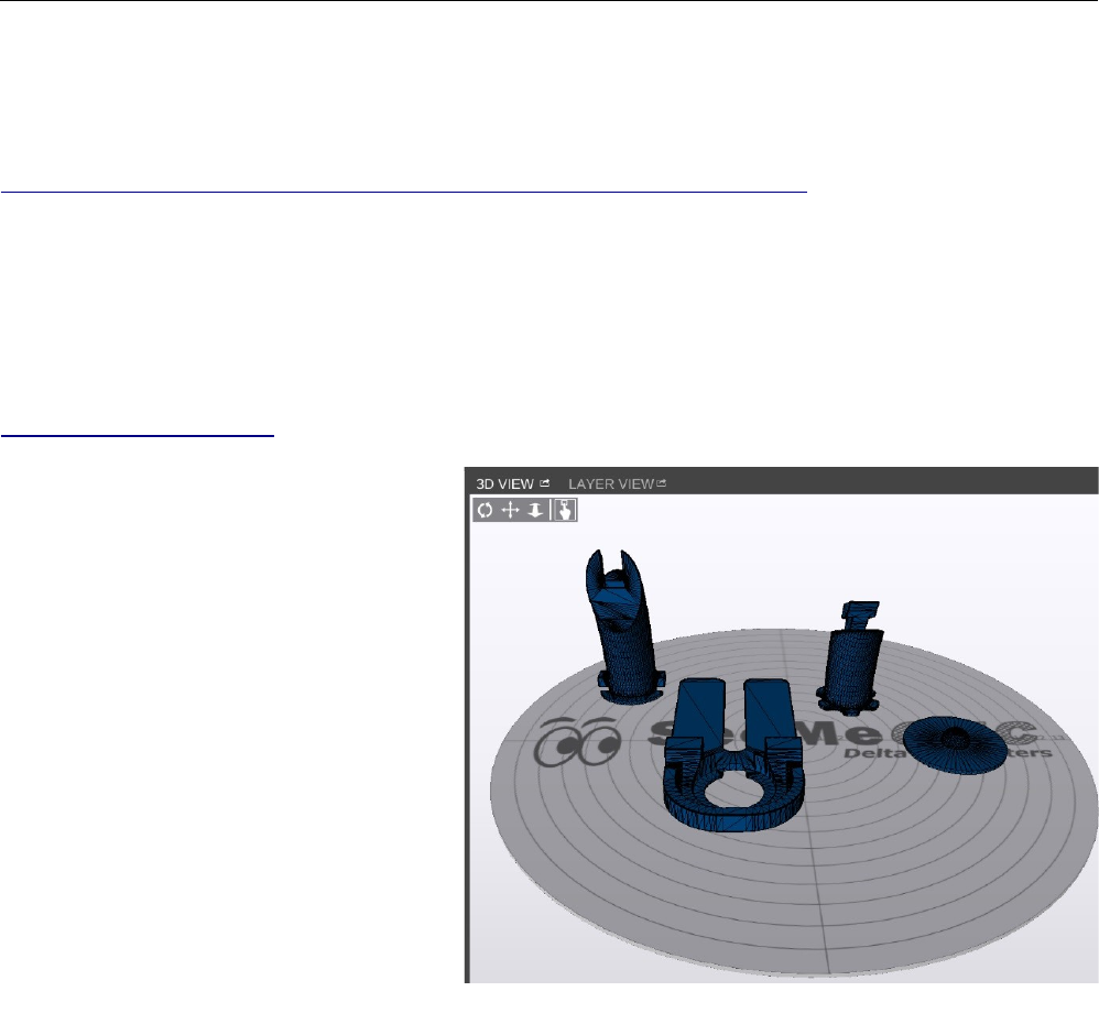
Rostock MAX v2 User's Guide
Appendix C: The MatterControl Touch
The MatterControl Touch is an Android based, 7” touch screen tablet that you can use in place
of a desktop or laptop computer. The features offered by the MatterControl Touch are essentially the
same as MatterControl. You'll get the same excellent feature set that MatterControl provides, along
with the ability to use the back-facing camera to take pics of your print jobs when they finish. For a
full list of what the MatterControl Touch can do, check it out on the MatterControl website:
http://www.matterhackers.com/store/printer-accessories/mattercontrol-touch.
One thing that you'll really appreciate with the MatterControl Touch is the ability it gives you to
run your Rostock MAX v2 without having to depend on having a desktop or laptop computer handy.
This Appendix is going to go over what you need to do in order to get the most out of your new
MatterControl Touch tablet and your freshly built Rostock MAX v2 3D printer!
The first thing you'll want to do is download and print the MatterControl Touch mount. This
mount is the same for both the Rostock MAX v2 and the Orion. You can find it here:
http://repables.com/r/497/.
You can “plate” the four smaller
parts like shown on the right. None of the
parts require support, except for the “MCT
Tablet Mount” component. However, that
part has support designed-in, so there's
nothing you need to do in order to add
support. I would recommend that if you're
printing with ABS that you add a 5mm or
so brim to the smaller parts job in order to
help them stick to the bed. That's how I
printed mine and they turned out great!
Appendix C: The MatterControl Touch - 119
Plating the smaller parts.
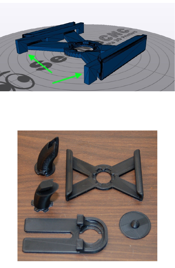
Rostock MAX v2 User's Guide
As I mentioned previously, the tablet mount itself has designed-in support, as shown below.
When you're done printing this part, the supports can be easily removed without damaging the
tablet support.
Here's what the printed tablet mount components look like.
Appendix C: The MatterControl Touch - 120
Designed-in support structures.
Successfully printed tablet mount components.
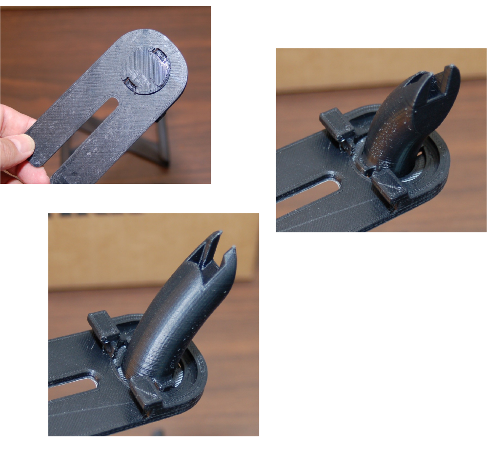
Rostock MAX v2 User's Guide
Once you've got the parts cleaned up, you'll need to assemble them. Begin by inserting the Arm
Base into the Base Mount as shown below.
The Arm Base is inserted into the Base Mount
from below. Once it's flush as shown to the left, you can
rotate the Arm Base 90 degrees into the “installed”
position.
Set these parts aside and we'll move on to installing the Arm Top into the Tablet Mount.
Appendix C: The MatterControl Touch - 121
Base Mount & Arm Base.
Arm Base ready to rotate.
Arm Base in installed position.
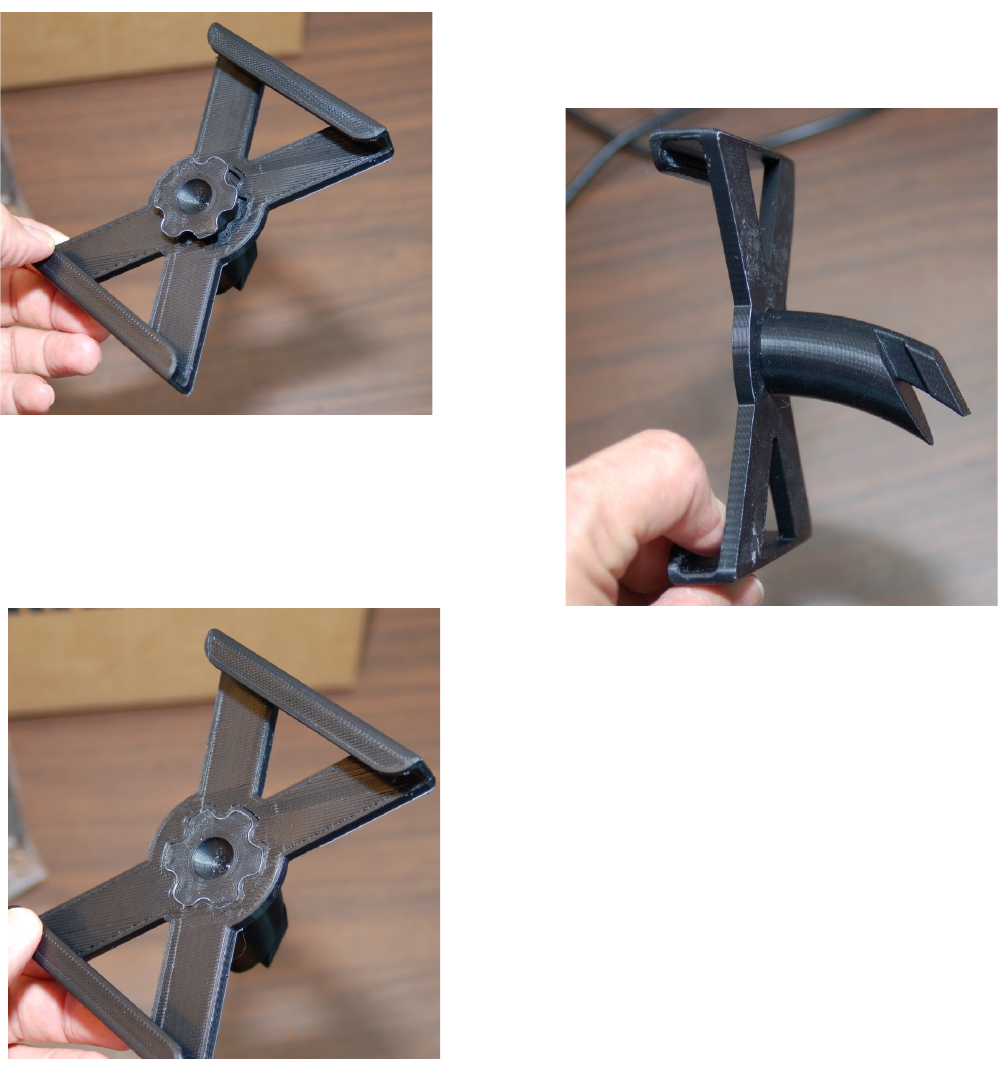
Rostock MAX v2 User's Guide
Insert the Arm Top into the Tablet Mount from the front as shown below.
Rotate the Arm Top such that when the tabs are
aligned with the pockets on the Tablet Mount, the tip of
the Arm Top is pointed “down” as shown below:
When you've got the Arm Top oriented properly,
press it into the arm seat on the Tablet Mount so that it's
flush with the upper surface of the Tablet Mount as shown
below.
Appendix C: The MatterControl Touch - 122
Arm Top inserted into Tablet Mount.
Arm Top orientation.
Arm Top fully seated.
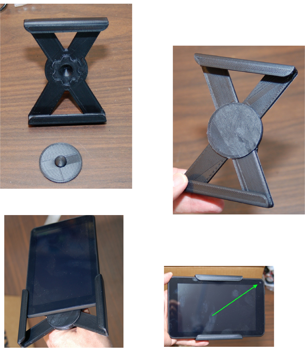
Rostock MAX v2 User's Guide
The Tablet Mount is designed a bit over-sized and won't properly hold the MatterControl Tablet
without a little help. This is where the Tablet Bumper comes into play.
The bump on the Tablet Bumper fits into the
shallow pocket in the center of the Arm Top. When you
slide your MatterControl Touch tablet into the mount, the
Tablet Bumper will ensure a snug fit into the mount.
Now slide the MatterControl Touch into the tablet mount!
Make sure the forward-facing camera is in the upper right
corner as shown below.
Appendix C: The MatterControl Touch - 123
Tablet Mount & Tablet Bumper.
Tablet Bumper in place.
Inserting the tablet into the mount. Installed!
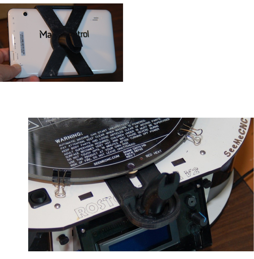
Rostock MAX v2 User's Guide
Now you can install the Base Mount on your Rostock MAX v2. As you can see below, the
mount slides right underneath the Onyx Heated Bed.
Appendix C: The MatterControl Touch - 124
View from behind.
Base Mount installed.
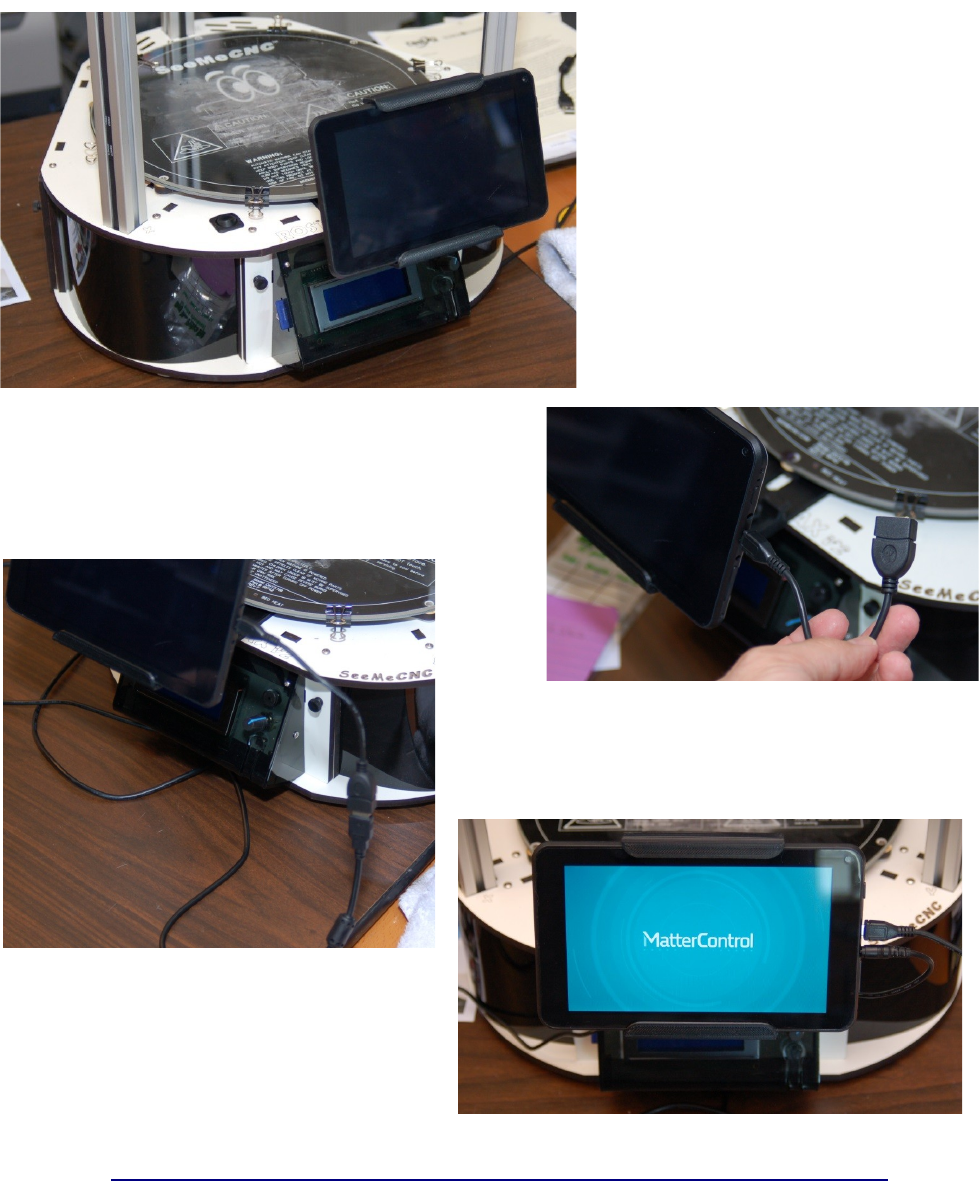
Rostock MAX v2 User's Guide
To finish the installation, insert the
Arm Top into the Arm Base as shown on
the left.
Now all you need to do is connect
your MatterControl Touch to your Rostock
MAX v2 using the included Micro USB to
USB-A adapter.
Insert the USB cable connected to your Rostock
MAX v2, and you're just about ready to go!
Now connect the power adapter included with the
MatterControl Touch and you're set!
Don't forget to check out the excellent
Getting Started guide over at MatterControl's
website!
http://www.matterhackers.com/articles/mattercontrol-touch-getting-started-guide
Appendix C: The MatterControl Touch - 125
Installation complete!
Micro USB to USB-A Adapter.
Connected!
Ready to Rock n' Roll!
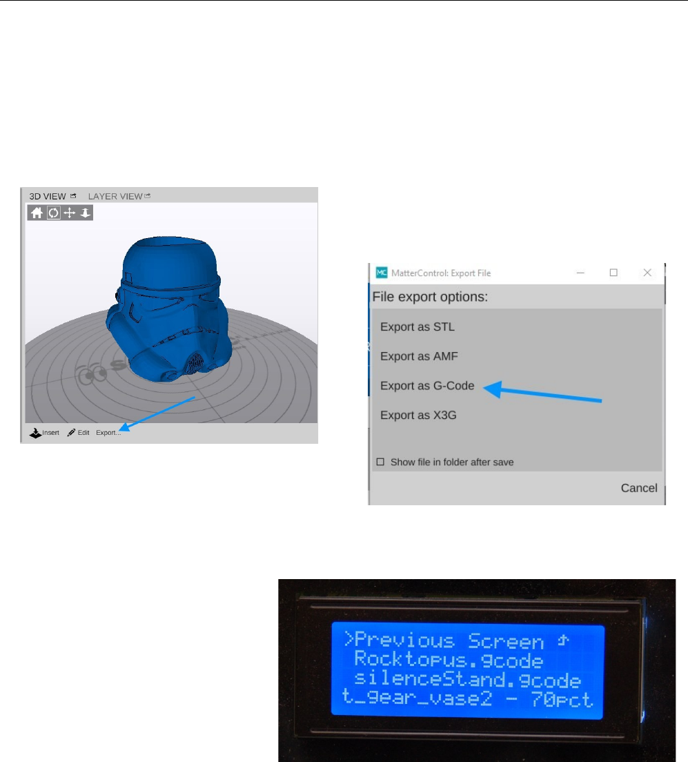
Rostock MAX v2 User's Guide
Appendix D: Printing From the SD Card
Your Rostock MAX v2 includes the ability to print without being connected to a host computer.
In order to do this, you'll need to save sliced files to the supplied SD card. This is really easy to do, but
will require that you have an SD card reader. If you don't have one, you can find one on Amazon for as
little as $10.
When you click “Print” in MatterControl, it begins sending GCODE to the Rostock MAX v2
over the USB link. In order to print from SD card, you'll need to save that GCODE to the SD card. In
order to do this, click the Export button as shown below:
When you click the Export button, you'll see the
dialog shown below.
Click on the Export as G-Code button and it'll
open a standard dialog box to allow you to save the file to your SD card. Once you've saved the file to
the SD card, eject it from your computer and insert it into the SD card slot. When you do this, the LCD
will display a list of files on the card. An example of this is shown below.
Use the control knob on the LCD
to scroll to the filename you just saved to
the SD card and press the knob in. This
will begin the printing process!
As the print job progresses, the
LCD display will show the print progress
as a percentage.
Appendix D: Printing From the SD Card - 126
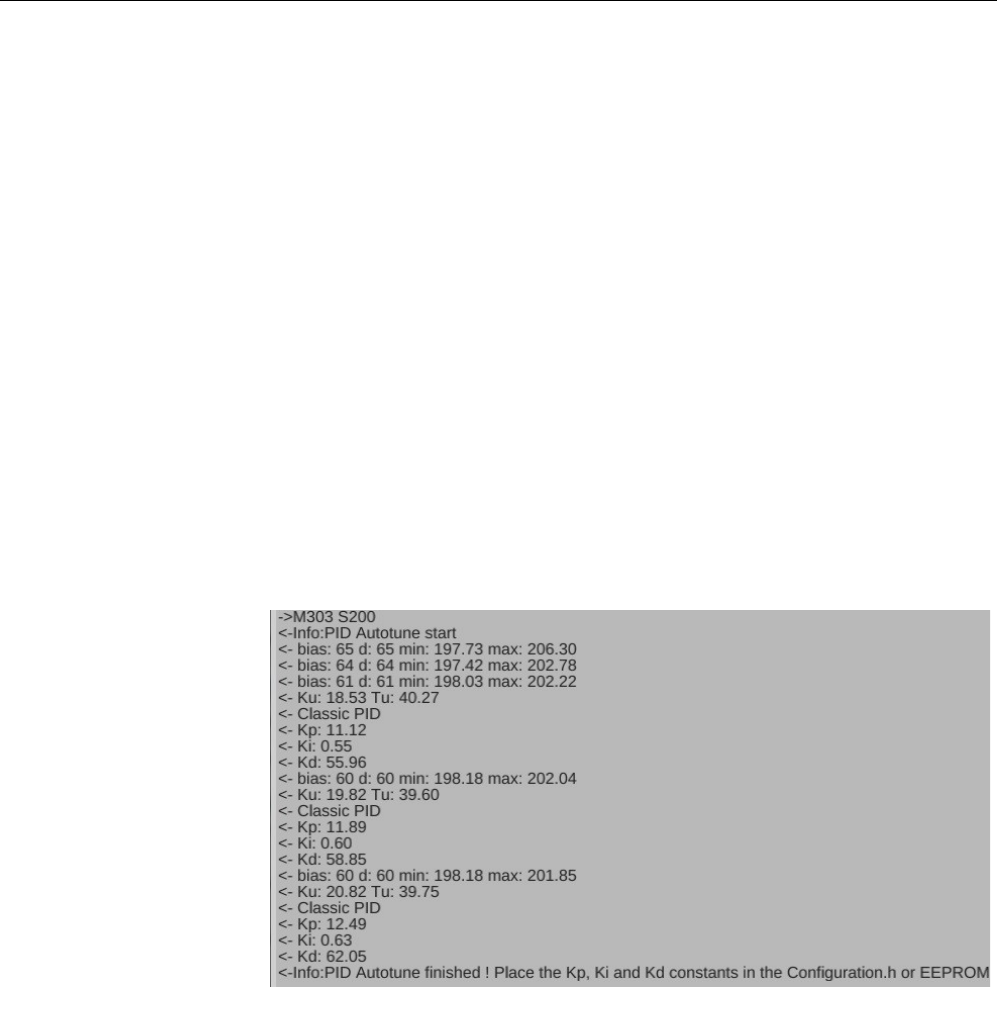
Rostock MAX v2 User's Guide
Appendix E: Optimizing The Temperature Control
Algorithms
It's important that the temperature controlling algorithm in the RAMBo (the PID loop) be as
accurate as possible. To do this, we need to run what is called the “PID Auto tune” routine. This is a
firmware function that you run in order to determine the best values for the P(roportional), I(ntegral)
and D(erivative) values used by the PID loop. Note that the only time you need to worry about the PID
loop is when you change hot ends. The default values included in the firmware have been tuned to
work best with the stock hot end. However, if you're replacing the stock hot end with something like a
genuine hotends.com J-Head or an E3D Volcano, you'll need to tweak the PID loop as they perform
differently than the stock hot end.
First, let's start the auto tune routine for the hot end. Open the terminal window as you have
before and send the command “M303 S200”. This begins the auto tune process and when it starts, it
begins to display information in the terminal window. The target temperature for this process is 200C
(that's what the “S200” is for).
It will begin with the entry, “PID Autotune start”. You'll notice that the temperature in the hot
end will begin to climb. A few minutes later, you'll start to see more information appear in the log
window.
The PID auto tune function is “learning” how to better manage the temperature in the hot end.
In a few minutes,
the routine will complete,
and you'll get output similar
to what you see on the
right. Enlarge the terminal
window so you can see the
whole process, from the
“Start” label to the
“Finished” label.
Appendix E: Optimizing The Temperature Control Algorithms - 127
Fig. E-1: PID Autotune results.
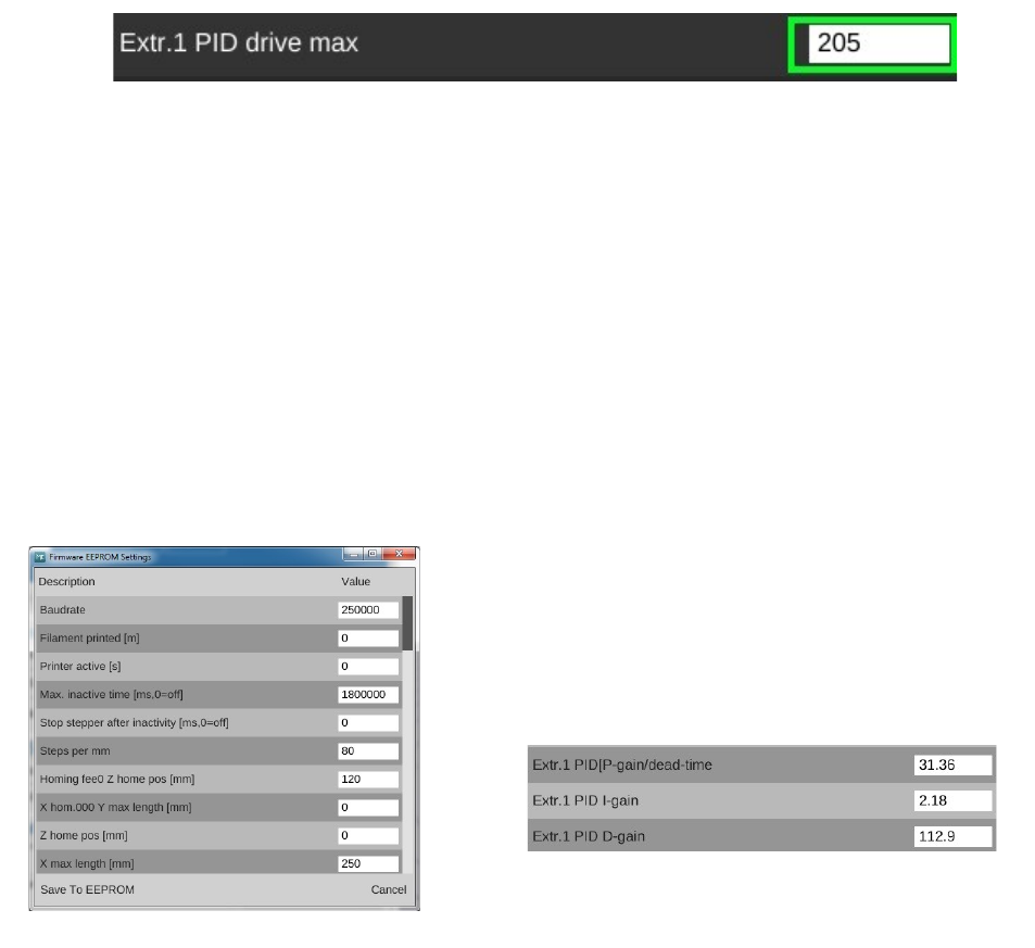
Rostock MAX v2 User's Guide
With some printer builds, the PID auto tune may abort with a message like this: “Error:PID
Autotune failed! Temperature to[sic] high”. This doesn't mean that something is broken, it simply
indicates that the RAMBo is applying too much power to the hot end during the auto tune process.
This results in an “overshoot” condition where the temperature goes 10+ degrees past the max set point
for the auto tune process. In order to fix this, you'll need to temporarily dial back the amount of power
being used on the hot end. You'll need to edit the setting, “Extr.1 PID drive max” parameter in the
EEPROM table.
The EEPROM table editor is on the same screen as the serial terminal. Click on the
“CONFIGURE” button next to EEProm Settings to open the editor. Scroll down to the parameter
shown below:
By default, this value is 205. Once you've gotten a successful auto-tune, you'll want to restore
that value. Change the value to 128 and then click on the “Save to EEPROM” button and then restart
the auto tune process once the hot end has cooled to room temperature.
Once the auto tune is completed, the values that you're interested in are the “Kp”, “Ki” and
“Kd” values. There are three blocks of these values, each under the heading “Classic PID”. Create an
average of all the values (add up all the Kp values, divide by three. Do the same with the Ki and Kd
values) and we'll get them added to the proper spot in the EEPROM table.
In order to store your new set of PID values, we need to open up the EEPROM table editor.
The EEPROM table editor is on the same screen as the terminal. Click on the CONFIGURE button
next to “EEProm Settings” to open the editor.
Scroll down until you see the fields highlighted in
green as shown below. Change the P-gain field to the value
you calculated for the average of Kp. Do the same for the
I-Gain (Ki) and D-Gain (Kd) values and then click the Save
To EEPROM button. That's all there is to it!
Appendix E: Optimizing The Temperature Control Algorithms - 128
Fig. E-3: EEPROM Table Editor.
Fig. E-4: Extruder PID settings.
Fig. E-2: PID Drive maximum.
