Lanzar Vibe VIBEX2 User’s Manual X2
User Manual: Lanzar Vibe VIBEX2 User’s Manual Troubleshoot Lanzar Vibe VIBEX2 |
Open the PDF directly: View PDF ![]() .
.
Page Count: 10
www.lanzar.com
1
INTRODUCTION
FEATURES:

2
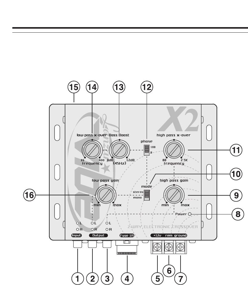
FUNCTIONS
1. SIGNAL INPUTS
To be connected to the output of the source unit.
2. LOW PASS SUBWOOFER OUTPUT TERMINALS
To be connected to the subwoofer channel amplifier left/right inputs.
3. HIGH PASS CHANNEL OUTPUT TERMINALS
To be connected to the channel amplifier left/right inputs.
4. FUSE
This crossover uses a 1-amp,blade-type fuses for protection from power surges or
a short circuit.
5. POWER INPUT TERMINAL (12V)
To be connected to the positive terminal of your vehicle battery or other constant
+12V source.
6. REMOTE TURN-ON INPUT TERMINAL (REMOTE)
To be connected to the remote control wire or antenna lead of the source unit for
remote ON/OFF.
7. GROUND INPUT TERMINAL
To be wired to the vehicle's chassis ground.
8. POWER INDICATOR
This indicator lights up when the internal switching power supply is activated and
the unit is operational.

3
9. HIGH PASS GAIN CONTROL
For adjusting the channel output signal level.
10. SUBWOOFER STEREO/MONO SWITCH
For selection of stereo or mono mode subwoofer output.
11. HIGH-PASS FREQUENCY SELECTOR
For selection of high-pass crossover frequency between 80 Hz and 2.5KHz
12. PHASE INVERTER
Position the switch to the "180" position shifts the subwoofer output signals 180
degrees out-of-phase relative to the front and rear output signals.
13. BASS-BOOST LEVEL CONTROL (45Hz)
For increasing the Bass boost level up to +12dB.
14. LOW PASS SUBWOOFER FREQUENCY SELECTOR
For selection of the low-pass crossover frequency for the subwoofer channel
between 35 Hz and 400 Hz.
15. SUBWOOFER OUTPUT LEVEL REMOTE CONTROL TERMINAL.
To be connected to the remote control for exclusive maneuver of the subwoofer
output level, and the subwoofer output level control on the unit ("16" below) is by-
passed.
16. LOW PASS SUBWOOFER OUTPUT GAIN CONTROL
For adjusting the subwoofer channel output signal level.
FUNCTIONS
4
ELECTRICAL & AUDIO CONNECTIONS

5
ELECTRICAL & AUDIO CONNECTIONS
Precautions
1. To prevent short circuits, be sure to disconnect the negative battery ground lead
before wiring the system up.
2. When you finish the installation, be sure to make one more check to be sure
everything is done correctly.
3. Reinstate all car parts that were removed.
4. Reconnect the negative battery ground lead.
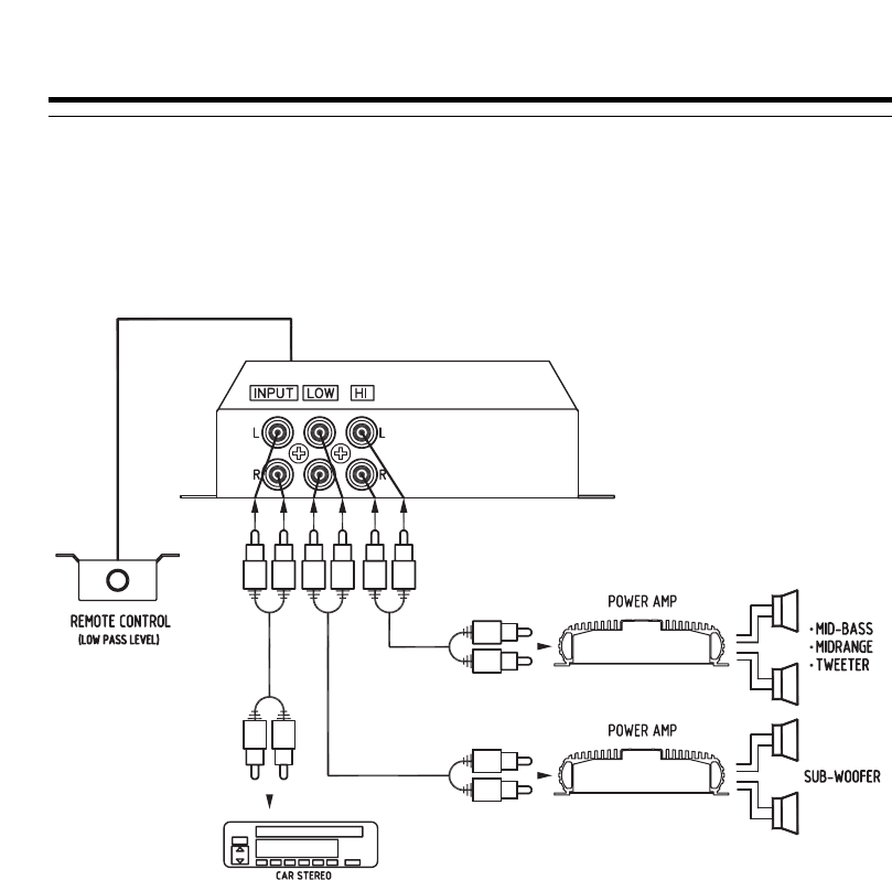
Primary Wiring Descriptions
ELECTRICAL
12V
PRIME CONNECTION
BATTERY + Connect to the positive battery terminal
(constant + 12V source)
GROUND GROUND - Connect to the vehicle's chassis ground
(check for good ground)
REMOTE REMOTE B+(12V) Connect to the remote control wire(or the
electrical antenna) of the car radio/cassette
deck
HIGH PASS
OUTPUT
CROSSOVER MODULE
TO ANY AMPLIFIER
Connect from "high-pass output" of
CROSSOVER module to any amplifier input.
LOW PASS
OUTPUT
CROSSOVER MODULE
TO SUB-WOOFER
AMPLIFIER
Connect from low-pass sub-woofer output of
CROSSOVER to sub-woofer amplifier input.
INPUT RADIO/TAPE
PLAYER TO
CROSSOVER MODULE
Connect from pre-amp output of radio/tape
player (or CD) into
DESCRIPTION
6
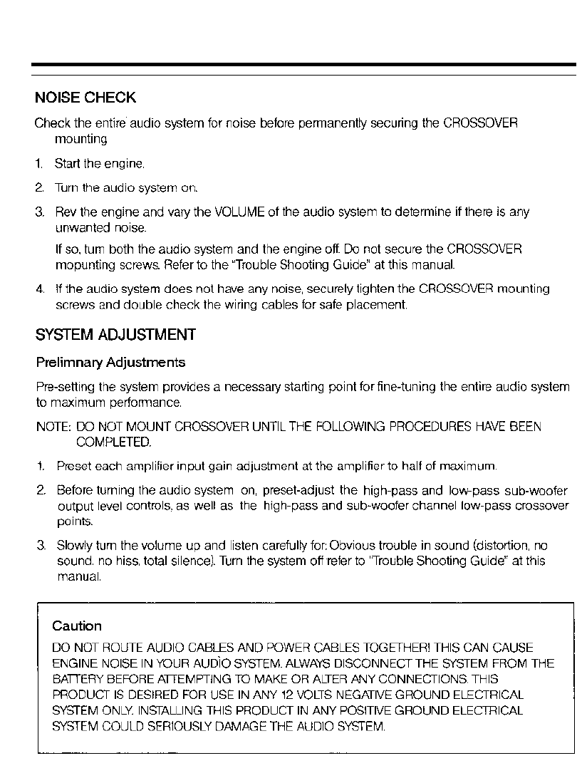
NOISE CHECK & SYSTEM ADJUSTMENT
7
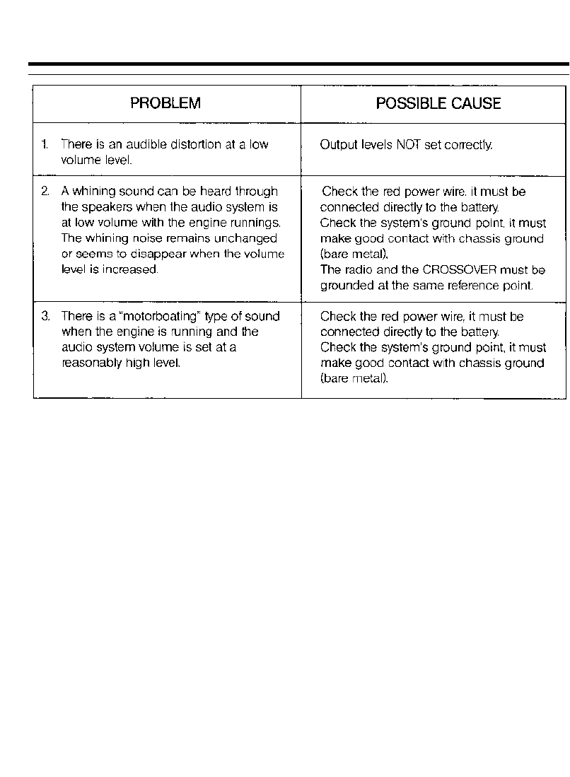
TROUBLE SHOOTING GUIDE
8
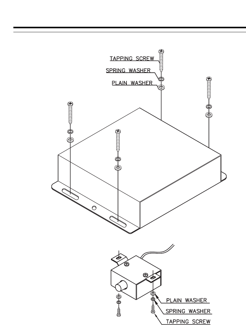
INSTALLATION
INSTALLATION

9
SPECIFICATIONS
SPECIFICATIONS
Power source: 14.4 volts DC negative ground
Input current 0.5 amp max
Distortion: 0.01% THD at 1 V output level
Frequency response: 10Hz-30KHz ±3 dB
S/N ratio (A weighted): >95dB
Separation: 60 dB
Crossover frequencies (continuously variable):
Low-pass: 35-400 Hz
High-pass: 80-2.5KHz
Crossover slope rate: 12 dB per octave 2nd Order Butter worth
Subwoofer boost: Single octave + 12dB at 45 Hz
Input impedance : > 10K Ohms
Output impedance <1K Ohms
Output voltage level: 5 volts max
Dimensions: 160mm (W) x 130mm (D) x 37mm (H)
FEATURES AND SPECIFICATIONS SUBJECT TO CHANGE AND / OR IMPROVEMENT
WITHOUT NOTICE.
