Irda2 Click Manual V100
User Manual:
Open the PDF directly: View PDF ![]() .
.
Page Count: 2
1. Introduction
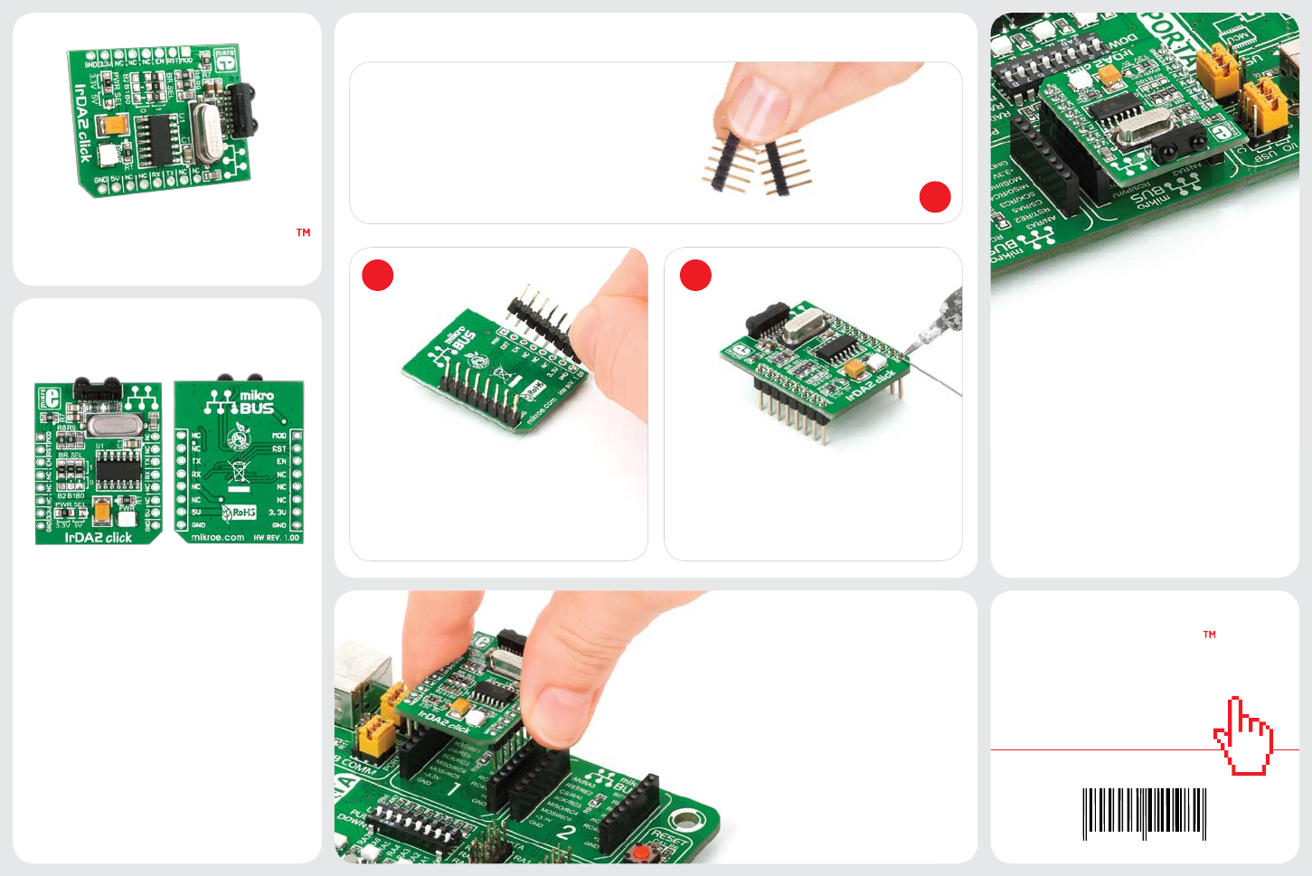
Once you have soldered the headers your
board is ready to be placed into desired
mikroBUS™ socket. Make sure to align the
cut in the lower-right part of the board
with the markings on the silkscreen at the
mikroBUS™ socket. If all of the pins are
aligned correctly, push the board all
the way into the socket.
3. Plugging the board in
2 3
2. Soldering the headers
1
4. Essential features
Turn the board upward again. Make sure
to align the headers so that they are
perpendicular to the board, then solder the
pins carefully.
Turn the board upside down so that
bottom side is facing you upwards. Place
shorter parts of the header pins in both
soldering pad locations.
IrDA2 click
Before using your click board™, make sure
to solder 1x8 male headers to both left
and right side of the board. Two 1x8 male
headers are included with the board in
the package.
click
BOARD
www.mikroe.com
IrDA2 click Manual
ver. 1.00
0 100000 020982
IrDA2 Click™ is an accessory board in
mikroBUS™ form factor. It’s a compact
and easy solution for adding infrared
communication to your device. It features
TFDU4101 infrared transceiver module as
well as MCP2120 infrared encoder/decoder
connected with the 7.3728 MHz external
crystal. IrDA2 Click™ communicates with
target board via UART interface. The board
is designed to use 3.3V and 5V power
supply. It has a LED diode (GREEN) that
indicates the presence of power supply.
The combination of the TFDU4101 and
MCP2120 results in support for fast and
stab le infrared data communication. The
TFDU4101 infrared transceiver module
covers the full IrDA range of more than
1m and speed up to 115.2 kbit/s. With low
power consumption, all these features make
this board ideal for TV and video systems,
printers, fax machines, copiers, external
infrared adapters, diagnostic systems and
other industrial applications.
8. Support
MikroElektronika oers Free Tech Support
(www.mikroe.com/esupport) until the
end of product lifetime, so if something goes
wrong, we are ready and willing to help!
7. Code Examples
.com
Once you have done all the necessary
preparations, it’s time to get your click
board up and running. We have provided
the examples for mikroC, mikroBasic and
mikroPascal compilers on our Libstock
website. Just download them and you are
ready to start.
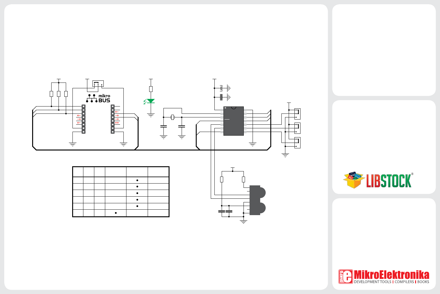
5. IrDA2 Click™ Board Schematic
1
2
3
4 11
12
13
14
5
6
7
10
9
8
AN
RST
CS
SCK
MOSI
MISO
+3.3V
GND
PWM
INT
RX
TX
SCL
SDA
+5V
GND
MIKROBUS DEVICE CONN.
R1
2K2
LD1
C1
100nF
VCC
OSC1
OSC2
RES RX
TX
EN
GND
RXIR
TXIR
MODE
BAUD0
BAUD1
BAUD2
U1
MCP2120
J3
VCC
PWR SEL
X1
7.3728MHz
C2
22pF
C3
22pF
R6
2.2
VCC
C4
100nF
R5
47
VCC
ENABLE
TX
RX
RESET#
MODE
VCC
RESET#
ENABLE TX
RX
MODE
E1
10uF
IR_a
NC
TXD
RXD
SD
VCC
NC
GND
U2
TFDU4101
VCC
R7
1K
R8
1K
R9
1K
VCC
B0
B1
B2
J0
J1
J2
1
1
1
0
0
0
C5
2.2uF
B2
0
B1
0
B0 Baud RateSoftware
selection
Hardware
selection (bps)
09600
0 0 1 19200
0 1 0 38400
0 1 1 57600
1 0 0 115200
1 1 1 9600
MikroElektronika assumes no responsibility or liability for any errors or inaccuracies that may appear in the present document.
Specication and information contained in the present schematic are subject to change at any time without notice. Copyright © 2012 MikroElektronika. All rights reserved.
6. SMD Jumpers
Jumpers J0, J1 and J2 connect MCP2120
controller BAUD0, BAUD1 and BAUD2 pins
to VCC or GND. You can change baud rate
settings by soldering J0, J1 and J2 in the
appropriate position (Table 1). These jumpers
are soldered in logic 1 position by default
(9600 bps, software selection enabled). SMD
jumper J3 is used to select 5V or 3.3V power
supply (default position is 3.3V).
Table 1: Baud rate selection
