ELDES ESIM364 Alarm system User Manual Part 1
ELDES Alarm system Part 1
UserManual.wiki
>
ELDES
>
ESIM364 User Manual
>
User Manual Part 1
Contents
1.
User Manual Part 1
2.
User Manual Part 2
User Manual Part 1
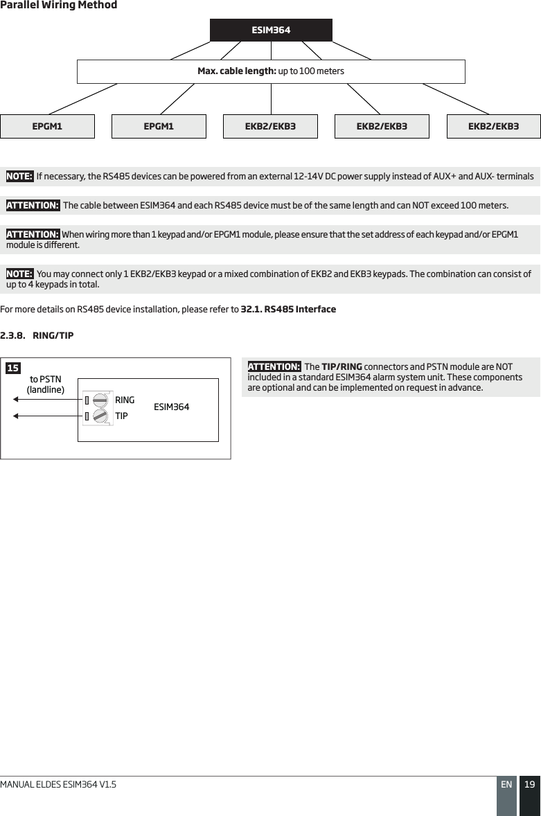
Navigation menu
Upload a User Manual
Namespaces
Wiki Guide
HTML
PDF
Info
Views
User Manual
Discussion / Help
Navigation


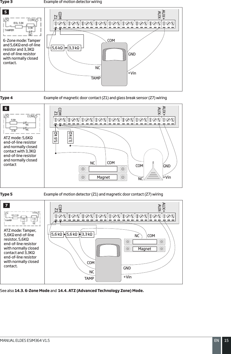
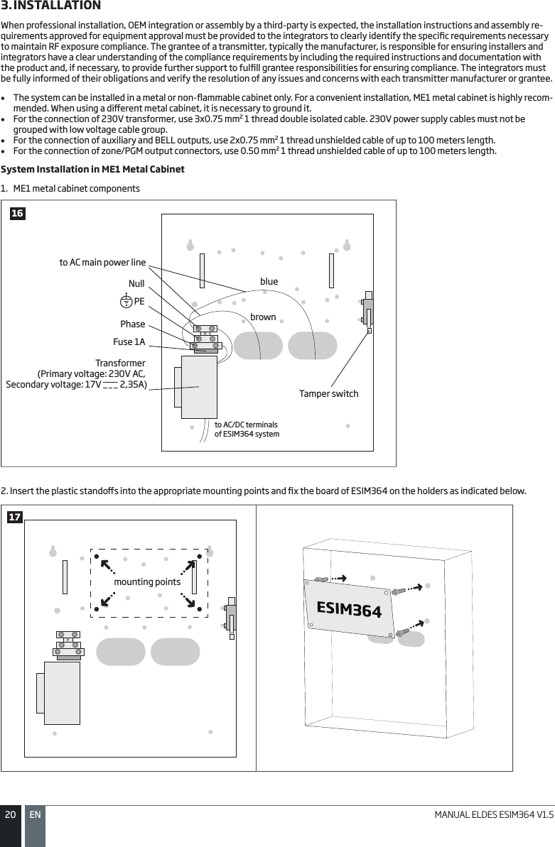
![2525ENMANUAL ELDES ESIM364 V1.55. CONFIGURATION METHODS!!! In this installation manual the underscore character ”_” represents one space character. Every underscore character must be replaced by a single space character. There must be no spaces or other unnecessary characters at the beginning and at the end of the SMS text message. EN50131-1GRADE 3To comply with EN50131-1 Grade 3 standard requirements, the system must be equipped with the following features: • All passwords must consist of 6 digits.• The system must prompt for SMS and administrator passwords (see 6. PASSWORDS) when conguring the system using ELDES Conguration Tool software.• The system must prompt for user (see 10. USER PASSWORDS) and administrator (see 6. PASSWORDS) passwords when conguring the system by EKB2, EKB3, EKB3W keypad.For complete list of EN50131-1 Grade 3 standard requirements and how to enable/disable the associated features, please refer to 35. EN 50131-1 GRADE 3. SMSIn order to congure and control the system by SMS text message, send the text command to the ESIM364 system phone number from one of the preset user phone numbers. The structure of SMS text message consists of 4-digit SMS password (the default SMS password is 0000 – four zeros), the parameter and value. For some parameters the value does not apply e. g. STATUS. The variables are indicated in lower-case letters, while a valid parameter value range is indicated in brackets.EKB2The system conguration and control by EKB2 keypad is carried out by navigating throughout the menu section list displayed on LCD screen. To navigate in the menu path, touch ↓, ↑ keys to select the desired menu section and touch OK key to open the selected section. To enter a required value, use 0... 9 keys and touch OK key for conrmation or cancel/go one menu section back by touching ← key. The value can be typed in directly by touching 0... 9 keys while highlighting the desired menu sec-tion. EKB2 menu type is “circle”, therefore when the last section in the menu list is selected, you will be brought back to the beginning of the list after touching the ↓ key. In this installation manual, the menu path is based on the EKB2 menu tree by starting at home screen view (see 32.1.1.6. EKB2 Menu Tree). The variables are provided in lower-case letters, while a valid parameter value range is provided in brackets.NOTE: Menu section CONFIGURATION is secured with administrator password. The default administrator password is 1470. NOTE: The system can be congured using only one keypad at a time. Other connected keypads will be inactive while the menu section CONFIGURATION is opened. The inactive EKB2 keypads will display icon and CONFIGURATION MODE message.NOTE: The keypad will automatically exit the menu section CONFIGURATION and return to home screen view if 1 minute after the last key-touch expires.EKB3/ EKB3WThe system conguration and control by EKB3/EKB3W keypad is carried out by activating the Conguration mode using the administrator password (by default – administrator password is 1470) and entering a valid conguration command using the number keys [0]... [9], [#] key for conrmation and [*] key to cancel the characters that are being entered. Alternatively, the user can wait for 10 seconds until the keypad buzzer will provide a long beep indicating that the entered characters have been cancelled. When typing in the characters, the indication of each pressed key is provided by short beep of keypad buzzer and red indicators when the number keys [0]... [9] are being pressed. Some commands require [BYPS], [CODE] and [STAY] keys as well. The structure of a standard conguration command is a combination of digits. The commands, which do not require the Conguration mode being activated, are noted. The variables are provided in lower-case letters, while a valid parameter value range is provided in brackets.NOTE: If you were not willing to activate Conguration mode, but accidentally typed in the * as the rst character, please press [*] key again or wait for 10 seconds until the keypad buzzer will provide a long beep indicating that the typed in characters have been cancelled. NOTE FOR EKB3W USERS: Even if Back-light Timeout has expired, the character will be considered as type in once the appropriate EKB3W key is pressed. For more details, please refer to 33.1.7. Wireless Communication, Sleep Mode and Back-light Timeout .Activate/deactivate Conguration mode EKB3/ EKB3WEnter administrator password:* aaaa #Value: aaaa – 4-digit administrator password.Example: *1470#EN50131-1GRADE 3 Activate/deactivate Conguration mode EKB3/ EKB3WEnter administrator and SMS passwords: * aaaaaa uuuuuu # Value: aaaaaa – 6-digit administrator password; uuuuuu – 6-digit user password.Example: *147000111111#](https://usermanual.wiki/ELDES/ESIM364.User-Manual-Part-1/User-Guide-2174368-Page-25.png)
![2727ENMANUAL ELDES ESIM364 V1.5Initiate theconnection tothird-party serverIn case it is necessary to establish a connection between ESIM364 system and a third-party conguration server, send the following SMS text message.SMSSMS text message content:ssss_STCONFIG:add.add.add.add:Port or ssss_STCONFIG:host-name:pprrt Value: ssss – 4-digit SMS password; add.add.add.add – public IP address of third-par-ty conguration server; pprrt – port number of third-party conguration server, ran-ge – [1... 65535]; host-name – public host-name of third-party conguration server. Example: 1111_STCONFIG:62.80.115.102:4522NOTE: Public IP address (host-name) and port number are necessary when connecting to a third-party-server for the rst time only. When connecting to the server next time, ssss_STCONFIG is enough as the IP address (host-name) and port number are saved in the device memory after the rst successful connection. Connecting to ELDES Conguration Server using ELDES Conguration Tool Software• Run ELDES Conguration Tool software.• Press Remote Conguration button.• In the next window, select Connect to Remote Server (recommended) and press Next button.• Enter the received IMEI number in Device IMEI entry.• Press Continue button.• Upon the successfully established connection, the system prompts for an administrator password.• By entering a valid administrator password, the sys tem grants access to full conguration remotely.• Remote Conguration Management window displays all performed conguration actions.31 Ending the Conguration ProcessShut down the Connection with the ServerAfter the system conguration is complete, use one of the following methods to end the conguration process:• Press Disconnect button and close ELDES Conguration Tool software;• Wait for the system to reply with an SMS text message conrming the end of the session;• Shut down the connection with the server at any time by sending an SMS text message.SMSSMS text message content:ssss_ENDCONFIGValue: ssss – 4-digit SMS password.Example: 1111_ENDCONFIG](https://usermanual.wiki/ELDES/ESIM364.User-Manual-Part-1/User-Guide-2174368-Page-27.png)
![2828 EN MANUAL ELDES ESIM364 V1.56. PASSWORDSFor security reasons, the system uses the following types of passwords:• SMS password – 4-digit password used for system arming/disarming and conguration by SMS text messages. By default, SMS pass-word is 0000, which MUST be changed!• Administrator password – 4-digit password used for Conguration mode activation by keypad and logging in to ELDES Conguration Tool software. By default, Administrator password is 1470, which is highly recommended to change.Set SMS password SMSSMS text message content:wwww_PSW_ssssValue: wwww – 4-digit default SMS password; ssss – 4-digit new SMS password; range – [0001... 9999].Example: 0000_PSW_1111EKB2Menu path:OK → CONFIGURATION → OK → aaaa → OK → PRIMARY SETTINGS → OK → PASSWORDS → OK → SMS PASSWORD → OK → ssss → OKValue: aaaa – 4-digit administrator password; ssss – 4-digit new SMS password; range – [0001... 9999].EKB3/ EKB3WEnter parameter 14 & new SMS password:14 ssss #Value: ssss – 4-digit new SMS password; range – [0001... 9999].Example: 141111#Cong Tool This operation may be carried out from the PC using the ELDES Conguration Tool software.Set Administrator password EKB2Menu path:OK → CONFIGURATION → OK → 1470 → OK → PRIMARY SETTINGS → OK → PASSWORDS → OK → ADMIN PASSWORD → OK → aaaa → OKValue: aaaa – 4-digit new administrator password; range – [0000... 9999].EKB3/ EKB3WEnter parameter 16 & new administrator password:16 aaaa #Value: aaaa – 4-digit new administrator password; range – [0000... 9999].Example: 162538#Cong Tool This operation may be carried out from the PC using the ELDES Conguration Tool software.EN50131-1GRADE 3To comply with EN50131-1 Grade 3 standard requirements, the system must be equipped with the following features: • All passwords must consist of 6 digits.• The system must prompt for SMS and administrator passwords when conguring the system using ELDES Conguration Tool software. • The system must prompt for user (see 10. USER PASSWORDS) and administrator passwords when conguring the sys-tem by EKB2, EKB3, EKB3W keypad.For complete list of EN50131-1 Grade 3 standard requirements and how to enable/disable the associated features, please refer to 35. EN 50131-1 GRADE 3.](https://usermanual.wiki/ELDES/ESIM364.User-Manual-Part-1/User-Guide-2174368-Page-28.png)
![3030 EN MANUAL ELDES ESIM364 V1.58. USER PHONE NUMBERSThe system supports up to 10 user phone numbers identied as User 1 through 10. When the phone number is set, the user will be able to arm/disarm the system by SMS text messages and free of charge phone calls (see 12.1. Free of Charge Phone Call and 12.2. SMS Text Message) as well as to congure the system by SMS text messages. User phone numbers are also used to receive alarm phone calls and SMS text messages from the system (see 17. ALARM INDICATIONS AND NOTIFICATIONS).By default, the system ignores any incoming calls and SMS text messages from a non-preset phone number as well as it rejects the SMS text messages containing wrong SMS password even from a preset user phone number (see 8.2. System Control from any Phone Number).To set User 1 phone number is mandatory, while the other 9 are optional. The supported phone number formats are the following:• International (with plus) – The phone numbers must be entered starting with plus and an international country code in the fol-lowing format: +[international code][area code][local number], example for UK: +4417091111111. This format can be used when setting up the phone number by SMS text message and ELDES Conguration Tool software.• International (with 00) – The phone numbers must be entered starting with 00 and an international country code in the following format: 00[international code][area code][local number], example for UK: 004417091111111. This format can be used when set-ting up the phone number by SMS text message, EKB2/EKB3/EKB3W keypad and ELDES Conguration Tool software.• Local – The phone numbers must be entered starting with an area code in the following format: [area code][local number], example for UK:017091111111. This format can be used when setting up the phone number by SMS text message, EKB2/ EKB3/EKB3W key-pad and ELDES Conguration Tool software.Set user phone number SMSSMS text message content:ssss_NRup:ttteeellnnuummValue: ssss – 4-digit SMS password; up – user phone number slot, range – [1... 10]; ttteeelln-nuumm – up to 15 digits user phone number.Example: 1111_NR1:+4417091111111EKB2Menu path:OK → CONFIGURATION → OK → aaaa → OK → PRIMARY SETTINGS → OK → CALL/SMS SETTINGS → OK → USERS → OK → USER 1... 10 → OK → PHONE NUMBER → OK → ttteeellnnuumm → OKValue: aaaa – 4-digit administrator password; ttteeellnnuumm – up to 15 digits user phone number.EKB3/ EKB3WEnter parameter 17, user phone number slot & phone number:17 up ttteeellnnuumm #Value: up – user phone number slot, range – [01... 10]; ttteeellnnuumm – up to 15 digits user phone number.Example: 1701004417091111111#Cong Tool This operation may be carried out from the PC using the ELDES Conguration Tool software.View user phone number SMSSMS text message content:ssss_HELPNRValue: ssss – 4-digit SMS password.Example: 1111_HELPNREKB2Menu path:OK → CONFIGURATION → OK → aaaa → OK → PRIMARY SETTINGS → OK → CALL/SMS SETTINGS → OK → USERS → OK → USER 1... 10 → OK → PHONE NUMBERValue: aaaa – 4-digit administrator password.Cong Tool This operation may be carried out from the PC using the ELDES Conguration Tool software.](https://usermanual.wiki/ELDES/ESIM364.User-Manual-Part-1/User-Guide-2174368-Page-30.png)
![3131ENMANUAL ELDES ESIM364 V1.5Delete user phone number SMSSMS text message content:ssss_NRup:DELValue: ssss – 4-digit SMS password; up – user phone number slot, range – [2... 10].Example: 1111_NR2:DELEKB2Menu path:OK → CONFIGURATION → OK → aaaa → OK → PRIMARY SETTINGS → OK → CALL/SMS SETTINGS → OK → USERS → OK → USER 2... 10 → OK → PHONE NUMBER → OK → OKValue: aaaa – 4-digit administrator password.Cong Tool This operation may be carried out from the PC using the ELDES Conguration Tool software.ATTENTION: NEVER add a phone number of the device’s SIM card as a user phone number!ATTENTION: Once User 1 phone number is set, it will be restricted to modify it only.NOTE: Multiple user phone numbers can be set by a single SMS text message, Example: 1111_NR1:+4417091111111_NR2:+4417091111112_NR6:017091111113_NR10:+4417091111114NOTE: Multiple user phone numbers can be deleted by a single SMS text message, Example: 1111_NR2:DEL_NR3:DEL_NR6:DEL_NR9:DEL_NR:10:DEL8.1. User Phone Number NamesWhen the system is armed or disarmed by free of charge phone call or SMS text message, the system sends a conrmation by SMS text mes-sage to user phone number that the system arming/disarming was initiated from. The SMS text message is sent regarding each partition separately and contains system status and partition name as well as it may contain a user name, set to the user phone number.Manage user phonenumber nameCong Tool This operation may be carried out from the PC using the ELDES Conguration Tool software.8.2. System Control from any Phone NumberBy default, the system ignores any incoming calls and SMS text messages from a non-preset phone number as well as it rejects the SMS text messages containing wrong SMS password even from a preset user phone number. To allow/disallow system arming/disarming by phone call and SMS text messages that contain a valid SMS password from any phone number, please refer to the following conguration methods.Enable system control from any phone numberSMSSMS text message content:ssss_STR:ONValue: ssss – 4-digit SMS password.Example: 1111_STR:ONEKB2Menu path:OK → CONFIGURATION → OK → aaaa → OK → PRIMARY SETTINGS → OK → CALL/SMS SETTINGS → OK → CTRL FROM ANY NUM → OK → ENABLE → OKValue: aaaa – 4-digit administrator password.EKB3/ EKB3WEnter parameter 12 & parameter status value:12 1 #Example: 121#Cong Tool This operation may be carried out from the PC using the ELDES Conguration Tool software.](https://usermanual.wiki/ELDES/ESIM364.User-Manual-Part-1/User-Guide-2174368-Page-31.png)
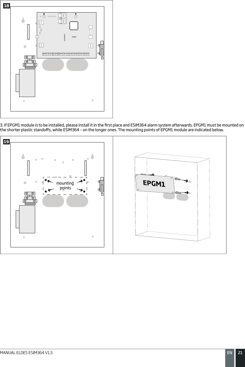
![3333ENMANUAL ELDES ESIM364 V1.59. DATE AND TIMEThe system comes equipped with internal real-time clock (RTC) that keeps track of the current date and time. Once the system is up and running, the user must set the correct date and time, otherwise the system will not operate properly. After shutting down and starting up the system, the date and time must be set again.Set date and time SMSSMS text message content:ssss_yyyy.mm.dd_hr:mnValue: ssss – 4-digit SMS password; yyyy – year; mm – month, range – [01... 12]; dd – day, range – [01... 31]; hr – hours, range – [00... 23]; mn – minutes, range – [00... 59].Example: 1111_2013.03.16_14:33EKB2Menu path:a) OK → DATE/TIME SETTINGS → OK →yyyy-mm-dd hr:mn → OKb) OK → CONFIGURATION → OK → aaaa → OK → PRIMARY SETTINGS → OK → DATE/TIME SETTINGS → OK → yyyy-mm-dd hr:mn → OKValue: aaaa – 4-digit administrator password; yyyy – year; mm – month, range – [01... 12]; dd – day, range – [01... 31]; hr – hours, range – [00... 23]; mn – minutes, range – [00... 59].EKB3/ EKB3WEnter parameter 66, date & time:66 yyyy mm dd hr mn#Value: yyyy – year; mm – month, range – [01... 12]; dd – day, range – [01... 31]; hr – hours, range – [00... 23]; mn – minutes, range – [00... 59].Example: 66201305291235#Cong Tool This operation may be carried out from the PC using the ELDES Conguration Tool software.NOTE: When the system is connected to the monitoring station via GPRS network connection (see 30. MONITORING STATION) and/or when Smart Security feature is in use (see 35. SMART SECURITY), the date and time will be automatically synchronized with the monitor-ing station or Smart Security server upon the system startup.](https://usermanual.wiki/ELDES/ESIM364.User-Manual-Part-1/User-Guide-2174368-Page-33.png)
![3434 EN MANUAL ELDES ESIM364 V1.510. USER PASSWORDSThe system supports up to 30 numeric user passwords, identied as User Password 1 through 30, allowing to carry out system arming/dis-arming by the keypad. By default, User Password 1 is preset as 1111 and assigned to Partition 1. For more details regarding user password partition, please refer to 23.4. User Password Partition.Set user password EKB2Menu path:User password 1... 16: OK → CONFIGURATION → OK → aaaa → OK → PRIMARY SETTINGS → OK → PASSWORDS → OK → USER PASSWORDS → OK → USER PSW (1-16) → OK → USER PASSWORD 1... 16 → OK → PASSWORDS → OK → uuuu → OK User password 17... 30: OK → CONFIGURATION → OK → aaaa → OK → PRIMARY SETTINGS → OK → PASSWORDS → OK → USER PASSWORDS → OK → USER PSW (17-30) → OK → USER PASSWORD 17... 30 → OK → PASSWORDS → OK → uuuu → OK Value: aaaa – 4-digit administrator password; uuuu – 4-digit user password, range – [0000... 9999].EKB3/ EKB3WEnter parameter 15, user password slot & user password:15 us uuuu #Value: us – user password slot, range – [01... 30]; uuuu – 4-digit user password; range – [0000... 9999].Example: 15021111#Cong Tool This operation may be carried out from the PC using the ELDES Conguration Tool software.Delete user password EKB2Menu path:OK → CONFIGURATION → OK → aaaa → OK → PRIMARY SETTINGS → OK → PASSWORDS → OK → USER PASSWORDS → OK → REMOVE PASSWORD → OK → uuuu → OK Value: aaaa – 4-digit administrator password; uuuu – 4-digit user password.EKB3/ EKB3WEnter parameter 65 & user password:65 uuuu #Value: uuuu – 4-digit user password.Example: 651111#Cong Tool This operation may be carried out from the PC using the ELDES Conguration Tool software.Replace user password EKB2Menu path:User password 1... 16: OK → CONFIGURATION → OK → aaaa → OK → PRIMARY SETTINGS → OK → PASSWORDS → OK → USER PASSWORDS → OK → USER PSW (1-16)→ OK → USER PASSWORD 1... 16 → OK → PASSWORD → OK → uuuu → OKUser password 17... 30: OK → CONFIGURATION → OK → aaaa → OK → PRIMARY SETTINGS → OK → PASSWORDS → OK → USER PASSWORDS → OK → USER PSW (17-30) → OK → USER PASSWORD 17... 30 → OK → PASSWORD → OK → uuuu → OKValue: aaaa – 4-digit administrator password; uuuu – 4-digit user password, range – [0000... 9999].EKB3/ EKB3WEnter parameter 63, existing user password & new user password:63 vvvv uuuu #Value: vvvv – 4-digit existing user password; uuuu – 4-digit new user password, range – [0000... 9999].Example: 6311113254#Cong Tool This operation may be carried out from the PC using the ELDES Conguration Tool software.NOTE: The system does not allow to set a duplicate password](https://usermanual.wiki/ELDES/ESIM364.User-Manual-Part-1/User-Guide-2174368-Page-34.png)
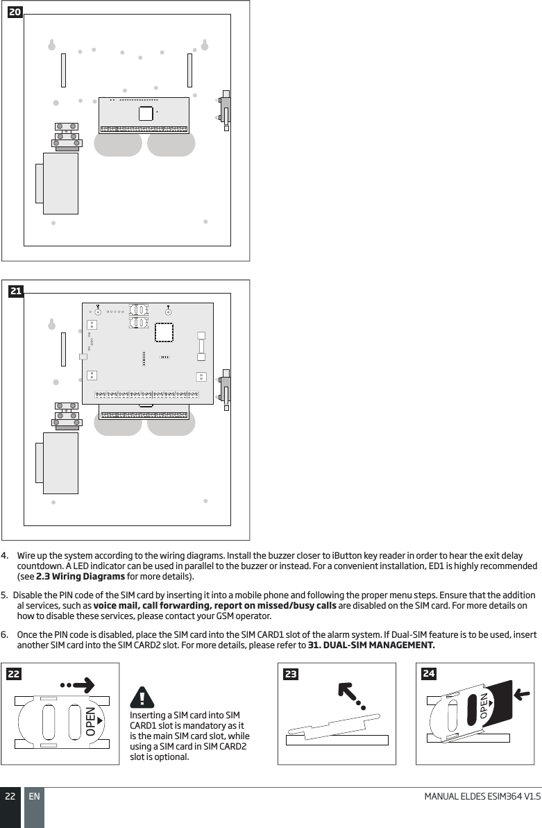
![3535ENMANUAL ELDES ESIM364 V1.5One of the user passwords ranging from User Password 1 through 10 can be set as SGS (Security Guard Service) password, which is used for system arming/disarming by a security service employee. When used, the SGS password will be identied by a unique Contact ID code in the monitoring station.Set SGS password EKB2Menu path:OK → CONFIGURATION → OK → aaaa → OK → PRIMARY SETTINGS → OK → PASSWORDS → OK → USER PASSWORDS → OK → SGS PASSWORD → OK → N/A / us → OK Value: aaaa – 4-digit administrator password; N/A – SGS password not in use; us – user pas-sword slot, range – [1... 10].EKB3/ EKB3WEnter parameter 74 & user password slot:74 us #Value: us – user password slot, range – [01... 10].Example: 7403#Cong Tool This operation may be carried out from the PC using the ELDES Conguration Tool software.The Duress password is used when system disarming is demanded by force. When used, the system will disarm as well as it will silently transmit an alert to the monitoring station. Only one of the user passwords ranging from User Password 1 through 10 can be set as Duress password.Set Duress password EKB2Menu path:OK → CONFIGURATION → OK → aaaa → OK → PRIMARY SETTINGS → OK → PASSWORDS → OK → USER PASSWORDS → OK → DURESS PASSWORD → OK → N/A / us → OKValue: aaaa – 4-digit administrator password; N/A – Duress password not in use; us – user password slot, range – [1... 10].EKB3/ EKB3WEnter parameter 73 & user password slot:73 us #Value: us – user password slot, range – [01... 10].Example: 7309#Cong Tool This operation may be carried out from the PC using the ELDES Conguration Tool software. EN50131-1GRADE 3To comply with EN50131-1 Grade 3 standard requirements, the system must be equipped with the following features: • All passwords must consist of 6 digits.• The system must prompt for user and administrator (see 6. PASSWORDS) passwords when conguring the system by EKB2, EKB3, EKB3W keypad.For complete list of EN50131-1 Grade 3 standard requirements and how to enable/disable the associated features, please refer to 35. EN 50131-1 GRADE 3. 10.1. User Password NamesWhen the system is armed or disarmed by entering a user password using a keypad, the system sends a conrmation by SMS text message to user phone number, sharing the same partition (-s) as the keypad and user password. The SMS text message is sent regarding each par-tition separately and contains system status and partition name as well as it may contain a user name, set to the user password.Manage userpassword nameCong Tool This operation may be carried out from the PC using the ELDES Conguration Tool software.](https://usermanual.wiki/ELDES/ESIM364.User-Manual-Part-1/User-Guide-2174368-Page-35.png)
![3939ENMANUAL ELDES ESIM364 V1.5When a user phone number is assigned to multiple partitions, the user will be able arm/disarm the corresponding system partitions by dialing the system’s phone number. For example, if User 1 is assigned to Partition 1, 2 and 3, the user will be able to arm/disarm Partition 1, 2 and 3 by a single phone call to the system from User 1 phone number. For more details on how to set user phone number partition, please refer to 23.2. User Phone Number Partition.CALLUser ESIM3643312.2. SMS Text MessageSMSTo arm the system by SMS text message, send the following text to the system‘s phone number from any of 10 available user phone numbers (see 8. USER PHONE NUMBERS for user phone number management). When the SMS text message for arm-ing is sent to the system’s phone number, the system will proceed as follows:• Non-partitioned system:• If ready (no violated zone/tamper), the system will arm. • If unready, the system will not arm and provide a list of violated zones/tampers by SMS text message to user phone number.• Partitioned system: • If all partitions are disarmed ready (no violated zone/tamper), the system will arm them. • If one or more partitions are disarmed unready (violated zone/tamper is present), the system will arm the ready par-tition (-s) and skip the unready one (-s). The system will then send an SMS text message, containing a list of violated zones/tampers, to user phone number that the system arming was initiated from.• If a combination of armed and disarmed ready partitions is present, the system will arm the disarmed ready partitions and skip the armed ones.Arm the systemSMS text message content:ssss_ARMp or ssss_ARMp,p,p,pValue: ssss – 4-digit SMS password; p – partition number, range – [1... 4].Example: 1111_ARM1SMSUser ESIM36434To disarm the system by SMS text message, send the following text to the system‘s phone number from any of 10 available user phone numbers:Disarm the systemSMS text message content:ssss_DISARMp or ssss_DISARMp,p,p,pValue: ssss – 4-digit SMS password; p – partition number, range – [1... 4].Example: 1111_DISARM1,2,4SMSUser ESIM36435](https://usermanual.wiki/ELDES/ESIM364.User-Manual-Part-1/User-Guide-2174368-Page-39.png)
![4040 EN MANUAL ELDES ESIM364 V1.5When a user phone number is assigned to multiple partitions, the user will be able arm/disarm the corresponding system partitions by sending the SMS text message to the system’s phone number. For example, if User 3 is assigned to Partition 2 and 3, the user will be able to arm/disarm Partition 2 and/or 3 by sending an SMS text message from User 3 phone number. For more details on how to set user phone number partition, please refer to 23.2. User Phone Number Partition.12.3. EKB2 Keypad and User PasswordEKB2 READY message displayed in the home screen view by EKB2 keypad indicates that no violated zones and/or tampers are pres-ent, therefore the system can be armed. If the message is displayed as NOT READY, the user must restore all violated zones and tampers before arming the system. Alternatively, the violated zones can be bypassed (see 14.7. Bypassing and Activat-ing Zones), disabled (see 14.9. Disabling and Enabling Zones) or a Force attribute enabled (see 14.6. Zone Attributes).To arm the system by EKB2 keypad, enter any out of 30 available 4-digit user passwords using the number keys on the keypad (see 10. USER PASSWORDS for user password management). By default, the system arming process is as follows: • Non-partitioned system – When a valid user password is entered, the system will initiate exit delay, the keypad’s buzzer will emit short beeps and the keypad will display icon next to the countdown timer. When the system is successfully armed, the keypad will display icon for 5 seconds and switch to home screen view.• Partitioned system; arming the same partition as the keypad is assigned to – When a valid user password is en-tered, the keypad will display the partition selection menu. Once a partition that is to be armed is selected, the system will initiate exit delay. During the exit delay, the keypad’s buzzer will emit short beeps and the keypad will display ARMING part-name message for 3 seconds followed by partition selection menu. If key is touched during exit delay, the keypad will display icon next to the countdown timer. When successfully armed, the keypad will display icon for 3 seconds and switch to home screen view. • Partitioned system; arming a dierent partition than the keypad is assigned to – When a valid user password is entered, the keypad will display the partition selection menu. Once a partition that is to be armed is selected, the system will initiate exit delay, but will not indicate it on EKB2 keypad due to the dierence between keypad partition and the one being armed. Then the keypad will display ARMING part-name message for 3 seconds followed by partition selection menu. When the keypad back-light timeout expires, the home screen view will follow.Arm the system 1742850396Enter user password/menu path:Non-partitioned system: uuuu → OKPartitioned system: uuuu → OK → [p] part-name → OKValue: uuuu – 4-digit user password; p – partition number, range – [1... 4], part-name – up to 15 characters partition name.Example: 1111 → OK → [2] PART2 → OKTo cancel the system arming process:• Non-partitioned system – Enter the user password again during exit delay countdown.• Partitioned system – Select the partition again, that is currently being armed, from the partition selection menu during exit delay countdown. The keypad will display part-name ARMING TERMINATED message followed by the partiton selection menu. When the keypad back-light timeout expires, the home screen view will follow.To disarm the system by EKB2 keypad, enter any out of 30 available 4-digit user passwords using the number keys on the keypad. By de-fault, the system disarming process is as follows:• Non-partitioned system – When a valid user password is entered, the keypad will display icon for 3 seconds and switch to home screen view.• Partitioned system – When a valid user password is entered, the keypad will display the partition selection menu. Once a partition that is to be disarmed is selected, the keypad will display part-name DISARMED message for 3 seconds and return to partition selec-tion menu followed by home screen view after the keypad back-light timeout expires.Disarm the system 1742850396Enter user password/menu path:Non-partitioned system: uuuu → OKPartitioned system: uuuu → OK → [p] part-name → OKValue: uuuu – 4-digit user password; p – partition number, range – [1... 4], part-name – up to 15 characters partition name.Example: 1111 → OK → [3] GARAGE → OK](https://usermanual.wiki/ELDES/ESIM364.User-Manual-Part-1/User-Guide-2174368-Page-40.png)
![4141ENMANUAL ELDES ESIM364 V1.5When a user password is assigned to multiple partitions, the user will be able arm/disarm the corresponding system partitions by EKB2 keypad using partition selection menu if one of the user password partitions correspond to the keypad partition. For example, if User Password 3 is assigned to Partition 1, 2 and 4, while EKB2 keypad is assigned to Partition 2, the user will be able to arm/disarm Partition 1, 2 and 4 by ente-ring User Password 3 and selecting the partitions from the partition selection menu. For more details on how to set keypad partition and user password partition, please refer to 23.3. Keypad Partition and Keypad Partition Switch and 23.4. User Password Partition.Alternatively to arm/disarm a dierent partition than the keypad is assigned to, use keypad partition switch feature (by default – disabled) before arming/disarming process. For more details on keypad partition switch and how to enable it, please refer to 23.3. Keypad Partition and Keypad Partition Switch. Use keypad partition switchMenu path:P1 → [p] part-name → OK Value: part-name – up to 15 characters partition name.NOTE: If the user fails to enter a correct user password 10 times in a row, the system will block the keypad for 2 minutes and the keypad will display KEYPAD BLOCKED message. While the keypad is blocked, the system prevents from entering any user password. The keypad will automatically unblock once the 2-minute time has expired and display KEYPAD UNBLOCKED message.12.4. EKB3 Keypad and User PasswordEKB3Illuminated indicator READY on EKB3 keypad indicates that no violated zones and/or tampers are present, therefore the system can be armed. If the indicator is not illuminated, the user must restore all violated zones and tampers before arming the system. Alternatively, the violated zones can be bypassed (see 14.7. Bypassing and Activating Zones), disabled (see 14.9. Disa-bling and Enabling Zones) or a Force attribute enabled (see 14.6. Zone Attributes).To arm the system by EKB3 keypad, enter any out of 30 available 4-digit user passwords using the number keys on the keypad (see 10. USER PASSWORDS for user password management). By default, when a valid user password is entered, the system will initiate exit delay, the keypad’s buzzer will emit short beeps and the indicator ARMED and the number [1]... [4] key, indicat-ing the partition that is to be armed, will light ON. When the system is successfully armed, the keypad’s buzzer will silent down.Arm the system 1742850396Enter user password:uuuuValue: uuuu – 4-digit user password.Example: 1111To cancel the system arming process, enter the user password again during exit delay countdown. To disarm the system by EKB3 keypad, enter any out of 30 available 4-digit user passwords using the number keys on the keypad. By de-fault, when a valid user password is entered, EKB3 keypad indicator ARMED and the number [1]... [4] key, indicating the partition that has been disarmed, will light OFF.Disarm the system 1742850396Enter user password:uuuuValue: uuuu – 4-digit user password.Example: 1111The system will arm/disarm the partition corresponding to the one that user password (see 23.4. User Password Partition) and the key-pad (see 23.3. Keypad Partition and Keypad Partition Switch) are assigned to. For example, if User Password 4 is assigned to Partition 2, 3 and 4, while EKB3 keypad is assigned to Partition 2, the user will be able to arm/disarm only Partition 2 by entering User Password 4. To arm/disarm a dierent partition than the keypad is assigned to, use keypad partition switch feature (by default – disabled) before arm-ing/disarming process. For more details on keypad partition switch and how to enable it, please refer to 23.3. Keypad Partition and Keypad Partition Switch. Use keypad partition switchHold the [1]... [4] key and release it after 3 short beeps:Value: [1]... [4] key – parition number 1... 4.](https://usermanual.wiki/ELDES/ESIM364.User-Manual-Part-1/User-Guide-2174368-Page-41.png)
![4242 EN MANUAL ELDES ESIM364 V1.5If 4 partitions exist in the system, user can arm/disarm all the partitions simultaneously. When this feature is used, the system will proceed as follows:• If all partitions are disarmed ready (no violated zone/tamper):• The system will initiate exit delay.• The keypad indicator ARMED along with number [1]... [4] keys will light ON.• The partitions will arm.• If one or more partitions are disarmed unready (keypad number [1]... [4] key ashing, indicating the partition that con-tains violated zone/tamper):• The system will initiate exit delay. • Keypad indicator ARMED (if the keypad is switched to a non-violated partition) along with number [1]... [4] keys will light ON.• The ready partition (-s) will arm and the unready one (-s) will be skipped. In such case the user must restore all violated zones and tampers before arming the system. Alternatively, the violated zones can be bypassed (see 14.7. Bypassing and Activating Zones), disabled (see 14.9. Disabling and Enabling Zones) or a Force attribute enabled (see 14.6. Zone Attributes).• If a combination of armed and disarmed ready partitions is present:• The system will initiate exit delay• The keypad indicator ARMED (if the keypad is switched to a disarmed partition) along with number [1]... [4] key (-s), indicating the partition (-s) that is to be armed, will light ON.• The disarmed ready partitions will be armed and the armed ones will be skipped.Arm/disarm all 4 partitions simultane-ously Hold the [0] key, release it after 3 short beeps and enter user password: 0 uuuuValue: uuuu – 4-digit user password.Example: 0 1111NOTE: To arm/disarm all partitions simultaneously, the user password must be assigned to all 4 partitions and the keypad partition switch feature enabled (see 23.3. Keypad Partition and Keypad Partition Switch).NOTE: The system will deny disarming all partitions simultaneously if at least one partition contains violated zone/tamper.NOTE: By default, User Password 1 is preset as 1111 and assigned to Partition 112.5. EKB3W Keypad and User PasswordEKB3WIlluminated indicator READY on EKB3W keypad indicates that no violated zones and/or tampers are present, therefore the sys-tem can be armed. If the indicator is not illuminated, the user must restore all violated zones and tampers before arming the system. Alternatively, the violated zones can be bypassed (see 14.7. Bypassing and Activating Zones), disabled (see 14.9. Disabling and Enabling Zones) or a Force attribute enabled (see 14.6. Zone Attributes).To arm the system by EKB3W keypad, enter any out of 30 available 4-digit user passwords using the number keys on the keypad (see 10. USER PASSWORDS for user password management). By default, when a valid user password is entered, the system will initiate exit delay, the keypad’s buzzer will emit short beeps and the indicator ARMED will light ON on EKB3W keypad. When the system is successfully armed, the keypad’s buzzer will silent down.Arm the system 1742850396Enter user password:uuuuValue: uuuu – 4-digit user password.Example: 1111To cancel the system arming process, enter the user password again during exit delay countdown. To disarm the system by EKB3W keypad, enter any out of 30 available 4-digit user passwords using the number keys on the keypad. By default, when a valid user password is entered, EKB3W keypad indicator ARMED will light OFF.Disarm the system 1742850396Enter user password:uuuuValue: uuuu – 4-digit user password.Example: 1111](https://usermanual.wiki/ELDES/ESIM364.User-Manual-Part-1/User-Guide-2174368-Page-42.png)
![4343ENMANUAL ELDES ESIM364 V1.5The system will arm/disarm the partition corresponding to the one that user password (see 23.4. User Password Partition) and the key-pad (see 23.3. Keypad Partition and Keypad Partition Switch) are assigned to. For example, if User Password 4 is assigned to Partition 2, 3 and 4, while EKB3W keypad is assigned to Partition 2, the user will be able to arm/disarm only Partition 2 by entering User Password 4. To arm/disarm a dierent partition than the keypad is assigned to, use keypad partition switch feature (by default – disabled) before arm-ing/disarming process. For more details on keypad partition switch and how to enable it, please refer to 23.3. Keypad Partition and Keypad Partition Switch. Use keypad partition switch Hold the [*] key, release it after 3 short beeps & enter partition number: * p Value: p – partition number, range – [1... 2] Example: *2 NOTE: Only Partition 1 and Partition 2 can be armed/disarmed using EKB3W keypad.NOTE: By default, User Password 1 is preset as 1111 and assigned to Partition 112.6. iButton Key To arm or disarm the system, touch the iButton key reader by any of 16 available iButton keys (see 11. iBUTTON KEYS for iBut-ton key management). When the iButton is touched to the iButton key reader for arming, the system will proceed as follows:• Non-partitioned system: • If ready (no violated zone/tamper), the system will initiate exit delay and arm. • If unready, the system will not arm and provide a list of violated zones/tampers by SMS text message to user phone number. In such case the user must restore all violated zones and tampers before arming the system. Alternatively, the violated zones can be bypassed (see 14.7. Bypassing and Activating Zones), disabled (see 14.9. Disabling and Enabling Zones) or a Force attribute enabled (see 14.6. Zone Attributes).• Partitioned system: • If all partitions are disarmed ready (no violated zone/tamper), the system will initiate exit delay and arm them. • If one or more partitions are disarmed unready (violated zone/tamper is present), the system will arm the ready par-tition (-s) and skip the unready one (-s). The system will then send an SMS text message, containing a list of violated zones/tampers, to user phone number, sharing the same partition (-s) as the iButton key. In such case the user must restore all violated zones and tampers before arming the system. Alternatively, the violated zones can be bypassed (see 14.7. Bypassing and Activating Zones), disabled (see 14.9. Disabling and Enabling Zones) or a Force at-tribute enabled (see 14.6. Zone Attributes).• If a combination of armed and disarmed ready partitions is present, the system will initiate exit delay, arm the dis-armed ready partitions and skip the armed ones.36When an iButton key is assigned to multiple partitions, the user will be able arm/disarm the corresponding system partitions by touching the iButton key to the reader. For example, if iButton 5 is assigned to Partition 1 and 4, the user will be able to arm/disarm Partition 1 and 4 by touching iButton 5 to the reader. For more details on how to set iButton key partition, please refer to 23.5. iButton Key Partition.](https://usermanual.wiki/ELDES/ESIM364.User-Manual-Part-1/User-Guide-2174368-Page-43.png)
![4444 EN MANUAL ELDES ESIM364 V1.512.7. EWK1/EWK2 Wireless KeyfobEWK1/EWK2To arm the system, press 1 of 4 keyfob buttons set to arm the system (by default, EWK1 – ;EWK 2 - ). When EWK1/EWK2 button is pressed for arming, the system will proceed as follows:• Non-partitioned/partitioned system: • If all partitions are disarmed ready (no violated zone/tamper), the system will initiate exit delay and arm them. • If unready, the system will not arm and provide a list of violated zones/tampers by SMS text message to user phone number. In such case the user must restore all violated zones and tampers before arming the system. Alternatively, the violated zones can be bypassed (see 14.7. Bypassing and Activating Zones), disabled (see 14.9. Disabling and Enabling Zones) or a Force attribute enabled (see 14.6. Zone Attributes).37To disarm the system, press 1 of 4 keyfob buttons set to disarm the system (by default, EWK1 - ; EWK2 - ).39The system will arm/disarm the partition corresponding to the one that EWK1/EWK2 wireless keyfob is assigned to (see 23.6. EWK1/ EWK2 Wireless Keyfob Partition). For example, if EWK1/EWK2 wireless keyfob is assigned to Partition 3, the user will be able to arm/ disarm only Partition 3. To arm a dierent partition than the EWK1/EWK2 wireless keyfob is assigned to, bind another EWK1/EWK2 keyfob to the system and assign it to a dierent partition. For more details on how to manage EWK1/EWK2 keyfob buttons, please refer to ELDES Conguration Tool software‘s HELP section. 12.8. Arm-Disarm by ZoneARM/ DISARMZONEThe Arm-Disarm by Zone feature allows to use a zone for arming and disarming the alarm system when the zone is violated and restored. The process is performed by providing a low-level pulse for more than 3 seconds into the specied zone. It means that violating and restoring the zone leads to system arming and by repeating this action the system becomes disarmed. The system will arm/disarm the partition (-s) that the zone is assigned to. This method can be set up for one on-board zone only.Set zone for Arm-Disarm by Zone methodEKB2Menu path:OK → CONFIGURATION → OK → aaaa → OK → ZONES → OK → ARM/DISARM BY ZONE → OK → ZONE 1... 12 → OKValue: aaaa – 4-digit administrator password.EKB3/ EKB3WEnter parameter 34 & on-board zone number:34 nn #Value: nn – on-board zone number, range – [01... 12].Example: 3403#Cong Tool This operation may be carried out from the PC using the ELDES Conguration Tool software.Arm the system38Disarm the system40Arm the systemDisarm the system](https://usermanual.wiki/ELDES/ESIM364.User-Manual-Part-1/User-Guide-2174368-Page-44.png)
![4545ENMANUAL ELDES ESIM364 V1.5Disable Arm-Disarm by Zone method EKB2Menu path:OK → CONFIGURATION → OK → aaaa → OK → ZONES → OK → ARM/DISARM BY ZONE → OK → N/A → OKValue: aaaa – 4-digit administrator password.EKB3/ EKB3WEnter parameter 34 & parameter status value34 00 #Example: 3400#Cong Tool This operation may be carried out from the PC using the ELDES Conguration Tool software.12.9. Disabling and Enabling Arm/Disarm NoticationsBy default, when the system is successfully armed or disarmed, it replies with conrmation by SMS text message to:• user phone number, sharing the same partition as EKB2/EKB3/EKB3W keypad and user password, iButton key, EWK1 wireless keyfob or zone, set up for Arm/Disarm by Zone method.• user phone number that the system arming/disarming by free of charge phone call was initiated from.• user phone number that the system arming/disarming by SMS text message was initiated from.The conrmation SMS text message is sent to the user phone number regarding each partition separately and contains system status and partition name as well as it may contain a user name assigned to user phone number, user password or iButton key. For more details on names, please refer to 8.1. User Phone Number Names, 10.1. User Password Names and 11.2. iButton Key Names.To disable/enable this notication for individual user phone number, please refer to the following conguration methods.Disable arm/disarm notication for individual user phone numberEKB2Menu path:OK → CONFIGURATION → OK → aaaa → OK → PRIMARY SETTINGS → OK → CALL/SMS SETTINGS → OK → USERS → OK → USER 1... 10 → OK → SEND ARM/DARM SMS → OK → DISABLE → OKValue: aaaa – 4-digit administrator password.EKB3/ EKB3WEnter parameter 75, user phone number slot & parameter status value:75 us 0 #Value: us – user phone number slot, range – [01... 10].Example: 75030#Cong Tool This operation may be carried out from the PC using the ELDES Conguration Tool software.Enable arm/disarm notication for individual user phone numberEKB2Menu path:OK → CONFIGURATION → OK → aaaa → OK → PRIMARY SETTINGS → OK → CALL/SMS SETTINGS → OK → USERS → OK → USER 1... 10 → OK → SEND ARM/DARM SMS → OK → ENABLE → OKValue: aaaa – 4-digit administrator password.EKB3/ EKB3WEnter parameter 75, user phone number slot & parameter status value:75 us 1 #Value: us – user phone number slot, range – [01... 10].Example: 75091#Cong Tool This operation may be carried out from the PC using the ELDES Conguration Tool software.By default, the system sends SMS text message only to the rst available user phone number when the system is successfully armed/disarmed. If the system did not receive the SMS delivery report during 20 seconds, it will attempt to send the SMS text message to the next preset user phone number. To ignore the SMS delivery report and allow/disallow the system to send the SMS text message to every preset user phone number, please refer to the following conguration methods.](https://usermanual.wiki/ELDES/ESIM364.User-Manual-Part-1/User-Guide-2174368-Page-45.png)
![4747ENMANUAL ELDES ESIM364 V1.513. EXIT AND ENTRY DELAYWhen arming, the system initiates the exit delay countdown (by default – 15 seconds) intended for the user to leave the secured area. The exit delay is indicated by short beeps emitted by EKB2/EKB3/EKB3W keypad buzzer and buzzer, connected to the alarm system. When arming:• a non-partitioned system, icon will be displayed next to the countdown timer on EKB2 keypad screen during exit delay.• a partitioned system, EKB2 keypad will display ARMING part-name message on the screen for 3 seconds and switch to partition selection menu during exit delay.Exit delay is provided when arming the system by the following methods:• EKB2/EKB3/EKB3W keypad and user password.• iButton key.• EWK1/EWK2 wireless keyfob.• Arm/Disarm by Zone.To arm the system without exit delay, use one of the following system arming methods:• Free of charge phone call.• SMS text message.• EGR100 middle-ware.Set exit delay SMSSMS text message content:ssss_EXITDELAY:p,ext or ssss_EXITDELAY:p,ext;p,ext;p,ext;p,extValue: ssss – 4-digit SMS password; p – partition number, range – [1... 4], ext – exit delay duration, range – [0... 600] seconds.Example: 1111_EXITDELAY:1,20;3,43EKB2Menu path:OK → CONFIGURATION → OK → aaaa → OK → PRIMARY SETTINGS → OK → EXIT DELAY → OK → PARTITION 1... 4 → OK → ext → OKValue: aaaa – 4-digit administrator password;, ext – exit delay duration, range – [0... 600] seconds.EKB3/ EKB3WEnter parameter 72, partition number & exit delay duration:72 pp ext #Value: pp – partition number, range – [01... 04], ext – exit delay duration, range – [0... 600] seconds.Example: 7203259#Cong Tool This operation may be carried out from the PC using the ELDES Conguration Tool software.NOTE: Alternatively, you can set exit delay value to 0 in order to arm the system without exit delay by any available method.Once the exit delay has expired, the system initiates the entry delay countdown (by default – 15 seconds) if a Delay type zone is violated. The countdown is indicated by short beeps emitted by keypad buzzer and by steady beep emitted by system’s buzzer. The indication is in-tended to advise the user that the system should be disarmed. Once the user presses/touches any key on the keypad during this delay, the buzzer of the keypad will be silenced. If the system is disarmed before the entry delay expires, no alarm will be caused.](https://usermanual.wiki/ELDES/ESIM364.User-Manual-Part-1/User-Guide-2174368-Page-47.png)
![4848 EN MANUAL ELDES ESIM364 V1.5Set entry delay for Delay zone SMSSMS text message content:ssss_ENTRYDELAY:nn,eeeee or ssss_ENTRYDELAY:nn,eeeee;nn,eeeee;nn,eeeee;nn,eeeee Value: ssss – 4-digit SMS password; nn – zone number, range – [1... 76], eeeee – entry delay duration, range – [0... 65535] seconds.Example: 1111_ENTRYDELAY:1,25;54,14;12,20EKB2Menu path:On-board zone: OK → CONFIGURATION → OK → aaaa → OK → ZONES → OK → ONBOARD ZONES → OK → ZONE 1... 12 → OK → ENTRY DELAY → OK → eeeee → OKWireless zone: OK → CONFIGURATION → OK → aaaa → OK → ZONES → OK → WIRELESS ZONES 1... 4 → OK → WIRELESS ZONE 13... 76 → OK → ENTRY DELAY → OK → eeeee → OKKeypad zone: OK → CONFIGURATION → OK → aaaa → OK → ZONES → OK → KEYPAD ZONES → OK → 1ST... 4TH KEYPAD ZONE → OK → ENTRY DELAY → OK → eeeee → OKEPGM1 zone: OK → CONFIGURATION → OK → aaaa → OK → ZONES → OK → EPGM1ZONES 1-16... EPGM1 ZONES 17... 32 → OK → EPGM1 ZONE 1... 32 → OK → ENTRY DELAY → OK → eeeee → OKValue: aaaa – 4-digit administrator password; eeeee – entry delay duration, range – [0... 65535] seconds.EKB3/ EKB3WEnter parameter 54, partition number and entry delay duration:54 nn eeeee #Value: nn – zone number, range – [01... 76], eeeee – entry delay duration, range – [0... 65535] secondsExample: 5403259#Cong Tool This operation may be carried out from the PC using the ELDES Conguration Tool software.NOTE: Due to battery power saving reasons, EKB3W keypad buzzer will not sound during exit and entry delay if the violated Delay type zone is not of the associated EKB3W keypad.For more details on zone types, please refer to 14.5. Zone Type Denitions.](https://usermanual.wiki/ELDES/ESIM364.User-Manual-Part-1/User-Guide-2174368-Page-48.png)
![5151ENMANUAL ELDES ESIM364 V1.5Set zone connection type for ATZ modeEKB2Menu path:OK → CONFIGURATION → OK → aaaa → OK → ZONES → OK → ZONE TYPE:ATZ MODE → OK → TYPE 4... 5 → OKValue: aaaa – 4-digit administrator password.EKB3/ EKB3WEnter parameter 38 & number of zone connection type: 38 1 # – Type 438 2 # – Type 5 Example: 381#Cong Tool This operation may be carried out from the PC using the ELDES Conguration Tool software.NOTE: The ATZ mode applies to on-board zones only when enabled.14.5. Zone Type Denitions• Interior Follower – The zone can be violated during exit and entry delay without causing an alarm. If the zone is violated before the entry delay has begun, it will cause an instant alarm. The zone is used where violating a zone during exit/entry delay is unavoidable. Typically, this zone is used for indoor protection devices, such as motion detectors, installed close to the exit/entry doors. • Instant – The alarm is instantly caused if this zone is violated when the system is armed or during entry delay. This zone type is usually used for doors, windows or other zones, and shock detectors. • 24-Hour – When the system is either armed or disarmed, the zone will cause instant alarm if violated. Normally, this type of zone is used for securing the areas that require constant supervisory. • Delay – This zone type can be violated during exit and entry delay without causing an alarm. If the zone is violated when the system is armed, it will initiate entry delay countdown intended for the user to disarm the system. If the zone is left violated after the exit delay expires, it will cause an instant alarm. If the zone is not violated and restored during exit delay, the system will be armed in Stay mode (see 15. STAY MODE). Typically, this zone type is used for door contacts installed at designated exit/entry doors. • Fire – If this zone type is violated when the system is either armed or disarmed, the alarm will be instantly caused and the siren/bell will emit pulsating sound. Typically, this zone type is used for ame and smoke detectors. • Panic/Silent – This zone operates the same as 24-Hour zone type, but the system will not activate the siren/bell and keypad buzzer if violated. Normally, this zone type used for panic alarm buttons. Set zone type for individual zoneEKB2Menu path:On-board zone: OK → CONFIGURATION → OK → aaaa → OK → ZONES → OK → ONBOARD ZONES → OK → ZONE 1... 12 → OK → TYPE → OK → INTERIOR FOLLOWER | INSTANT | 24-HOUR | DELAY | FIRE | PANIC/SILENT → OK Wireless zone: OK → CONFIGURATION → OK → aaaa → OK → ZONES → OK → WIRELESS ZONES 1... 4 → OK → WIRELESS ZONE 13... 76 → OK → TYPE → OK → INTERIOR FOLLOWER | INSTANT | 24-HOUR | DELAY | FIRE | PANIC/SILENT → OK Keypad zone: OK → CONFIGURATION → OK → aaaa → OK → ZONES → OK → KEYPAD ZONES → OK → 1ST... 4TH KEYPAD ZONE → OK → TYPE → OK → INTERIOR FOLLOWER | INSTANT | 24-HOUR | DELAY | FIRE | PANIC/SILENT → OK EPGM1 zone: OK → CONFIGURATION → OK → aaaa → OK → ZONES → OK → EPGM1 ZONES 1-16... EPGM1 ZONES 17-32 → OK → EPGM1 ZONE 1... 32 → OK → STAY → OK → ENABLE → OK Value: aaaa – 4-digit administrator password.EKB3/ EKB3WEnter parameter 53, zone number & zone type number:53 nn 1 # – Interior Follower 53 nn 2 # – Instant53 nn 3 # –24-Hour 53 nn 4 # – Delay53 nn 5 # – Fire53 nn 6 # – Panic/SilentValue: nn – zone number, range – [01... 76]Example: 53125#Cong Tool This operation may be carried out from the PC using the ELDES Conguration Tool software.](https://usermanual.wiki/ELDES/ESIM364.User-Manual-Part-1/User-Guide-2174368-Page-51.png)
![5252 EN MANUAL ELDES ESIM364 V1.5NOTE: The system will NOT activate siren/bell and keypad buzzer only when Panic/Silent zone type is violated.14.6. Zone Attributes• Stay – If this attribute is enabled, the zone, regardless of type, will not cause an alarm if violated when the system is Stay armed. For more details on arming the system in the Stay mode, please refer to 15. STAY MODE.• Force – This attribute determines whether the system can be armed or not while a zone is violated. If a zone with the Force attribute enabled is left violated until the exit delay expires, it will be ignored. Once the system is armed and the zone is restored, the violation will not be ignored and the zone will operate according to the determined type. For more details on zone types, please refer to 14.5. Zone Type Denitions.• Shared – This attribute determines whether a zone, assigned to multiple partitions, will cause an alarm or not in the associated armed partition if violated. If a zone with the Shared attribute enabled is violated when at least one of the associated partitions is disarmed, the alarm will not be caused. Once the system is armed in all of the associated partitions, the zone with Shared attribute enabled will operate according to the determined type. Typically, this attribute is used for shared areas, such as corridors.• Delay, ms – This attribute determines the zone sensitivity level by delay time (By default – 800 milliseconds). If a zone is left triggered until the delay time expires, the zone is considered violated.• Delay becomes Instant in Stay mode – This attribute determines whether or not any Delay type zone will operate as Instant type zone when the system is armed in the Stay mode. When the system is fully armed, the Delay type zone will operate normally. For more details on Delay and Instant zone types, please refer to 14.5. Zone Type Denitions.• Chime – This feature is used to emit 3 short beeps from the keypad buzzer and display icon on EKB2 keypad screen whenever any Delay type zone is violated. Typically, the feature is used for designated exit/entry doors to indicate the opening of the doors.NOTE: Due to battery power saving reasons, EKB3W wireless keypad buzzer will not sound if the Bell attribute is not enabled and the vio-lated Delay type zone is not of the associated EKB3W wireless keypad. For more details on EKB3W wireless keypad, please refer to 33.2.1. EKB3W – Wireless LED Keypad.Enable Stay attribute for individual zoneEKB2Menu path:On-board zone: OK → CONFIGURATION → OK → aaaa → OK → ZONES → OK → ONBOARD ZONES → OK → ZONE 1... 12 → OK → STAY → OK → ENABLE → OKWireless zone: OK → CONFIGURATION → OK → aaaa → OK → ZONES → OK → WIRELESS ZONES 1... 4 → OK → WIRELESS ZONE 13... 76 → OK → STAY → OK → ENABLE → OKKeypad zone: OK → CONFIGURATION → OK → aaaa → OK → ZONES → OK → KEYPADZONES → OK → 1ST... 4TH KEPAD ZONE → OK → STAY → OK → ENABLE → OKEPGM1 zone: OK → CONFIGURATION → OK → aaaa → OK → ZONES → OK → EPGM1 ZONES 1-16... EPGM1 ZONES 17-32 → OK → EPGM1 ZONE 1... 32 → OK → STAY → OK → ENABLE → OK Value: aaaa – 4-digit administrator password.EKB3/ EKB3WEnter parameter 56, zone number & parameter status value:56 nn 1 #Value: nn – zone number, range – [01... 76].Example: 56041#Cong Tool This operation may be carried out from the PC using the ELDES Conguration Tool software.](https://usermanual.wiki/ELDES/ESIM364.User-Manual-Part-1/User-Guide-2174368-Page-52.png)
![5353ENMANUAL ELDES ESIM364 V1.5Disable Stay attribute for individual zoneEKB2Menu path:On-board zone: OK → CONFIGURATION → OK → aaaa → OK → ZONES → OK → ONBOARD ZONES → OK → ZONE 1... 12 → OK → STAY → OK → DISABLE → OKWireless zone: OK → CONFIGURATION → OK → aaaa → OK → ZONES → OK → WIRELESS ZONES 1... 4 → OK → WIRELESS ZONE 13... 76 → OK → STAY → OK → DISABLE → OKKeypad zone: OK → CONFIGURATION → OK → aaaa → OK → ZONES → OK → KEYPADZONES → OK → 1ST... 4TH KEYPAD ZONE → OK → STAY → OK → DISABLE → OKEPGM1 zone: OK → CONFIGURATION → OK → aaaa → OK → ZONES → OK → EPGM1 ZONES 1-16... EPGM1 ZONES 17-32 → OK → EPGM1 ZONE 1... 32 → OK → STAY → OK → DISABLE → OK Value: aaaa – 4-digit administrator password.EKB3/ EKB3WEnter parameter 56, zone number & parameter status value:56 nn 0 #Value: nn – zone number, range – [01... 76].Example: 56190#Cong Tool This operation may be carried out from the PC using the ELDES Conguration Tool software.Enable Force attribute for individual zoneEKB2Menu path:On-board zone: OK → CONFIGURATION → OK → aaaa → OK → ZONES → OK → ONBOARD ZONES → OK → ZONE 1... 12 → OK → FORCE → OK → ENABLE → OKWireless zone: OK → CONFIGURATION → OK → aaaa → OK → ZONES → OK → WIRELESS ZONES 1... 4 → OK → WIRELESS ZONE 13... 76 → OK → FORCE → OK → ENABLE → OKKeypad zone: OK → CONFIGURATION → OK → aaaa → OK → ZONES → OK → KEYPADZONES → OK → 1ST... 4TH KEYPAD ZONE → OK → FORCE → OK → ENABLE → OKEPGM1 zone: OK → CONFIGURATION → OK → aaaa → OK → ZONES → OK → EPGM1 ZONES 1-16... EPGM1 ZONES 17-32 → OK → EPGM1 ZONE 1... 32 → OK → FORCE → OK → ENABLE → OK Value: aaaa – 4-digit administrator password.EKB3/ EKB3WEnter parameter 82, zone number & parameter status value:82 nn 1 #Value: nn – zone number, range – [01... 76].Example: 82061#Cong Tool This operation may be carried out from the PC using the ELDES Conguration Tool software.Disable Force attribute for individual zoneEKB2Menu path:On-board zone: OK → CONFIGURATION → OK → aaaa → OK → ZONES → OK → ONBOARD ZONES → OK → ZONE 1... 12 → OK → FORCE → OK → DISABLE → OKWireless zone: OK → CONFIGURATION → OK → aaaa → OK → ZONES → OK → WIRELESS ZONES 1... 4 → OK → WIRELESS ZONE 13... 76 → OK → FORCE → OK → DISABLE → OKKeypad zone: OK → CONFIGURATION → OK → aaaa → OK → ZONES → OK → KEYPADZONES → OK → 1ST... 4TH KEYPAD ZONE → OK → FORCE → OK → DISABLE → OKEPGM1 zone: OK → CONFIGURATION → OK → aaaa → OK → ZONES → OK → EPGM1 ZONES 1-16... EPGM1 ZONES 17-32 → OK → EPGM1 ZONE 1... 32 → OK → STAY → OK → DISABLE → OK Value: aaaa – 4-digit administrator password.EKB3/ EKB3WEnter parameter 82, zone number & parameter status value:82 nn 0 #Value: nn – zone number, range – [01... 76].Example: 82110#Cong Tool This operation may be carried out from the PC using the ELDES Conguration Tool software.](https://usermanual.wiki/ELDES/ESIM364.User-Manual-Part-1/User-Guide-2174368-Page-53.png)
![5454 EN MANUAL ELDES ESIM364 V1.5Enable/disable Shared attribute for individual zoneCong Tool This operation may be carried out from the PC using the ELDES Conguration Tool software. Set Delay, ms atrribute Cong Tool This operation may be carried out from the PC using the ELDES Conguration Tool software.Enable/disable Delay becomes Instant in Stay mode attributeCong Tool This operation may be carried out from the PC using the ELDES Conguration Tool software.Disable Chime attributeEKB2 Menu path:OK → CONFIGURATION → OK →aaaa → OK → ZONES → OK → CHIME → OK → DISABLE → OK Value: aaaa – 4-digit administrator password.EKB3/ EKB3WEnter parameter 32 & parameter status value:32 0 #Example: 320#Cong Tool This operation may be carried out from the PC using the ELDES Conguration Tool software.Enable Chime attribute EKB2 Menu path:OK → CONFIGURATION → OK → aaaa → OK → ZONES → OK → CHIME → OK → ENABLE → OK Value: aaaa – 4-digit administrator password.EKB3/ EKB3WEnter parameter 32 & parameter status value:32 1 #Example: 321#Cong Tool This operation may be carried out from the PC using the ELDES Conguration Tool software.14.7. Bypassing and Activating ZonesATTENTION: Zone bypassing and activation must be carried out without Conguration mode being activated by the EKB3/EKB3W keypad.Zone bypassing allows the user to deactivate a violated zone and arm the system without restoring the zone. If a bypassed zone is violated or restored during exit/entry delay, or when then system is armed, it will be ignored. When a zone is bypassed, EKB3/EKB3W keypad indi-cator BYPS will light ON and EKB2 keypad will display BYP message in the home screen view.Bypass individual violated zoneEKB2Menu path:OK → BYPASS → OK → BYPASS LIST 1... 5 → OK → Z1-zone-name... Z76-zone-name → OK → BYPASS → OKValue: zone-name - up to 24 characters zone name.EKB3/ EKB3WPress the [BYPS] key, enter zone number & user password:BYPS nn uuuu #Value: nn – zone number, range – [01... 76]; uuuu – 4-digit user password.Example: BYPS091111#](https://usermanual.wiki/ELDES/ESIM364.User-Manual-Part-1/User-Guide-2174368-Page-54.png)
![5555ENMANUAL ELDES ESIM364 V1.5Bypass all violated zonesEKB2 Menu path:OK → BYPASS → OK → BYP VIOLATED ZONES → OKThe zone will stay bypassed until the system is disarmed. Once the system is disarmed, the corresponding zone state will be indicated on the keypads (see 32.1.1. EKB2 – LCD Keypad, 32.1.2. EKB3 – LED Keypad and 33.1. EKB3W – Wireless LED Keypad) and Info SMS text message (see 26. SYSTEM INFORMATION. INFO SMS). Alternatively, the user can activate the bypassed zone by the following conguration methods.Activate bypassed zoneEKB2Menu path:OK → BYPASS → OK → BYPASS LIST 1... 5 → OK → Z1-zone-name... Z76-zone-name → OK → UNBYPASS → OK Value: zone-name - up to 24 characters zone name.EKB3/ EKB3WPress the [BYPS[ key, enter zone number & user password:BYPS nn uuuu #Value: nn – zone number, range – [01... 76]; uuuu – 4-digit user password.Example: BYPS251111# NOTE: Zones can only be bypassed and activated when the system is not armed.14.8. Zone NamesEach zone has a name that can be customized by the user. Typically, the name species a device type connected to a determined zone terminal, for Example: Kitchen doors opened. The zone names are used in SMS text messages that are sent to the user during alarm. the By default, the zone names are: Z1 – Zone1, Z2 – Zone2, Z3 – Zone3, Z4 – Zone4 etc.Set zone name SMSSMS text message content:ssss_Znn:zone-nameValue: ssss – 4-digit SMS password; nn – zone number, range – [1... 76]; zone-name – up to 24 characters zone name.Example: 1111_Z3:Door sensor triggeredCong Tool This operation may be carried out from the PC using the ELDES Conguration Tool software.View zone names SMSSMS text message content:ssss_STATUSValue: ssss – 4-digit SMS password.Example: 1111_STATUSEKB2EKB2:Menu path:On-board zone: OK → CONFIGURATION → OK → aaaa → OK → ZONES → OK → ONBOARD ZONES → OK → ZONE 1... 12 → OK → NAMEWireless zone: OK → CONFIGURATION → OK → aaaa → OK → ZONES → OK → WIRELESS ZONES 1... 4 → OK → WIRELESS ZONE 13... 76 → OK → NAMEKeypad zone: OK → CONFIGURATION → OK → aaaa → OK → ZONES → OK → KEYPAD ZONES → OK → 1ST... 4TH KEYPAD ZONE → OK → NAMEEPGM1 zone: OK → CONFIGURATION → OK → aaaa → OK → ZONES → OK → EPGM1 ZONES 1-16... EPGM1 ZONES 17-32 → OK → EPGM1 ZONE 1... 32 → OK → NAME Value: aaaa – 4-digit administrator password.Cong Tool This operation may be carried out from the PC using the ELDES Conguration Tool software.](https://usermanual.wiki/ELDES/ESIM364.User-Manual-Part-1/User-Guide-2174368-Page-55.png)
![5656 EN MANUAL ELDES ESIM364 V1.5ATTENTION: Colon, semi-colon characters, parameter names and/or values, such as PSW, STATUS, ON, OFF etc. are NOT allowed in zone namesNOTE: Multiple zone names can be set by a single SMS text message, Example: 1111_Z1:Kitchen doors opened;Z3:Movement in base-ment;Z4:Bedroom window opened14.9. Disabling and Enabling ZonesBy default, all zones, except keypad and virtual zones, are enabled. To permanently disable/enable an individual zone, please refer to the following conguration methods.Disable zone SMSSMS text message content:ssss_Znn:OFFValue: ssss – 4-digit SMS password; nn – zone number, range – [1... 76].Example: 1111_Z13:OFFEKB2Menu path:On-board zone: OK → CONFIGURATION → OK → aaaa → OK → ZONES → OK → ONBOARD ZONES → OK → ZONE 1... 12 → OK → STATUS → OK → DISABLE → OKWireless zone: OK → CONFIGURATION → STATUS → aaaa → OK → ZONES → OK → WIRELESS ZONES 1... 4 → OK → WIRELESS ZONE 13... 76 → OK → STATUS → OK → DISABLE → OKKeypad zone: OK → CONFIGURATION → OK → aaaa → OK → ZONES → OK → KEYPAD ZONES → OK → 1ST... 4TH KEYPAD ZONE → OK → STATUS → DISABLE → OKEPGM1 zone: OK → CONFIGURATION → OK → aaaa → OK → ZONES → OK → EPGM1 ZONES 1-16... EPGM1 ZONES 17-32 → OK → EPGM1 ZONE 1... 32 → OK → STATUS → DISABLE → OK Value: aaaa – 4-digit administrator password.EKB3/ EKB3WEnter parameter 52, zone number & parameter status value:52 nn 0 #Value: nn – zone number, range – [01... 76].Example: 52360#Cong Tool This operation may be carried out from the PC using the ELDES Conguration Tool software.Enable zone SMSSMS text message content:ssss_Znn:ONValue: ssss – 4-digit SMS password; nn – zone number, range – [1... 76].Example: 1111_Z6:ONEKB2Menu path:On-board zone: OK → CONFIGURATION → OK → aaaa → OK → ZONES → OK → ONBOARD ZONES → OK → ZONE 1... 12 → OK → STATUS → OK → ENABLE → OKWireless zone: OK → CONFIGURATION → OK → aaaa → OK → ZONES → OK → WIRELESS ZONES 1... 4 → OK → WIRELESS ZONE 13... 76 → OK → STATUS → OK → ENABLE → OKKeypad zone: OK → CONFIGURATION → OK → aaaa → OK → ZONES → OK → KEYPAD ZONES → OK → 1ST... 4TH KEYPAD ZONE → OK → STATUS → ENABLE → OKEPGM1 zone: OK → CONFIGURATION → OK → aaaa → OK → ZONES → OK → EPGM1 ZONES 1-16... EPGM1 ZONES 17-32 → OK → EPGM1 ZONE 1... 32 → OK → STATUS → ENABLE → OK Value: aaaa – 4-digit administrator password.EKB3/ EKB3WEnter parameter 52, zone number & parameter status value:52 nn 1 #Value: nn – zone number, range – [01... 76].Example: 52151#Cong Tool This operation may be carried out from the PC using the ELDES Conguration Tool software.](https://usermanual.wiki/ELDES/ESIM364.User-Manual-Part-1/User-Guide-2174368-Page-56.png)
![5757ENMANUAL ELDES ESIM364 V1.515. STAY MODEStay mode allows the user to arm and disarm the alarm system without leaving the secured area. If the zones with Stay attribute enabled are violated when the system is Stay armed, no alarm will be caused. Typically, this feature is used when arming the system at home before going to bed.The system can be Stay armed under the following conditions: • If a zone with Stay attribute enabled is NOT violated during exit delay, the system will arm in Stay mode. When arming the system in Stay mode under this condition, one of the available arming methods must be used that provide exit delay. For more details on these methods, please refer to 13. EXIT AND ENTRY DELAY. • The system will instantly arm in Stay mode when using one of the following methods.Arm the system in Stay mode EKB2Menu path:Non-partitioned system: P2 → uuuu → OKPartitioned system: P2 → uuuu → OK → [p] part-name → OKValue: uuuu – 4-digit user password; p – partition number, range – [1... 4]; part-name – up to 15 characters partition name.EKB3/ EKB3WPress the [STAY] key & enter user password:STAY uuuuValue: uuuu – 4-digit user password.Example: STAY1111When the system is successfully armed in Stay mode, EKB2 keypad will display STAY message in the home screen view.ATTENTION: System arming in Stay mode by the keypad must be carried out without Conguration mode being activated.NOTE: The system can be armed in Stay mode, only if there is at least one zone with Stay attribute enabled.NOTE: Stay mode is not supported by virtual zones.For more details on how to enable Stay attribute for zone, please refer to 14.6. Zone Attributes.](https://usermanual.wiki/ELDES/ESIM364.User-Manual-Part-1/User-Guide-2174368-Page-57.png)
![6464 EN MANUAL ELDES ESIM364 V1.5Cong Tool This operation may be carried out from the PC using the ELDES Conguration Tool software.Disable EPGM8 mode EKB2Menu path:OK → CONFIGURATION → OK → aaaa → OK → PGM OUTPUTS → OK → USING EPGM8 → OK → DISABLE → OKValue: aaaa – 4-digit administrator password.EKB3/ EKB3WEnter parameter 33 & parameter status value:33 0 #Example: 330#Cong Tool This operation may be carried out from the PC using the ELDES Conguration Tool software.18.3. PGM Output NamesEach PGM output has a name that can be customized by the user. Typically, the name species a device type connected to a determined PGM output, for Example: Lights. The name can be used instead of PGM output number when controlling the PGM output by SMS text message. By default, the PGM output names are: C1 – Controll1, C2 – Controll2, C3 – Controll3, C4 – Controll4 etc.Set PGM output name SMSSMS text message content:ssss_Coo:out-nameValue: ssss – 4-digit SMS password; oo – PGM output number, range – [1... 76]; out-name – up to 16 characters PGM output name.Example: 1111_C2:LightsCong Tool This operation may be carried out from the PC using the ELDES Conguration Tool software.View PGM output names SMSSMS text message content:ssss_STATUSValue: ssss – 4-digit SMS password.Example: 1111_STATUSEKB2Menu path:On-board PGM output: OK → CONFIGURATION → OK → aaaa → OK → PGM OUTPUTS → OK → ONBOARD OUTPUTS → OK → OUTPUT 1... 12 → OK → NAMEWireless PGM output: OK → CONFIGURATION → OK → aaaa → OK → PGM OUTPUTS → OK → WIRELESS OUTPUTS 1... 4 → OK → OUTPUT 13... 76 → OK → NAMEValue: aaaa – 4-digit administrator password.Cong Tool This operation may be carried out from the PC using the ELDES Conguration Tool software.ATTENTION: Space, colon, semi-colon characters, parameter names and/or values, such as PSW, STATUS, ON, OFF etc. are NOT allowed in PGM output names.18.4. Turning PGM Outputs ON and OFF](https://usermanual.wiki/ELDES/ESIM364.User-Manual-Part-1/User-Guide-2174368-Page-64.png)
![6565ENMANUAL ELDES ESIM364 V1.5By default, all PGM outputs are turned OFF. To instantly turn ON/OFF an individual PGM output and set its state to ON/OFF when the system starts-up, please refer to the following conguration methods.Turn ON PGM output/Set PGM output start-up state as ONSMSSMS text message content:ssss_Coo:ON or ssss_out-name:ONValue: ssss – 4-digit SMS password; oo – PGM output number, range – [1... 76]; out-name – up to 16 characters PGM output name.Example: 1111_Lights:ONEKB2Menu path:On-board PGM output: OK → CONFIGURATION → OK → aaaa → OK → PGM OUTPUTS → OK → ONBOARD OUTPUTS → OK → OUTPUT 1... 12 → OK → STATUS → OK → ENABLED → OKWireless PGM output: OK → CONFIGURATION → OK → aaaa → OK → PGM OUTPUTS → OK → WIRELESS OUTPUTS 1... 4 → OK → OUTPUT 13... 76 → OK → STATUS → OK → ENABLED → OKValue: aaaa – 4-digit administrator password.EKB3/ EKB3WEnter parameter 61, PGM output number & parameter status value:61 oo 1 #Value: oo – PGM output number, range – [01... 76].Example: 61031#Cong Tool This operation may be carried out from the PC using the ELDES Conguration Tool software.Turn OFF PGM output/Set PGM output start-up state as OFFSMSSMS text message content:ssss_Coo:OFF or ssss_out-name:OFFValue: ssss – 4-digit SMS password; oo – PGM output number, range – [1... 76]; out-name – up to 16 characters PGM output name.Example: 1111_C2:OFFEKB2Menu path:On-board PGM output: OK → CONFIGURATION → OK → aaaa → OK → PGM OUTPUTS → OK → ONBOARD OUTPUTS → OK → OUTPUT 1... 12 → OK → STATUS → OK → DISABLED → OKWireless PGM output: OK → CONFIGURATION → OK → aaaa → OK → PGM OUTPUTS → OK → WIRELESS OUTPUTS 1... 4 → OK → OUTPUT 13... 76 → OK → STATUS → OK → DISABLED → OKValue: aaaa – 4-digit administrator password.EKB3/ EKB3WEnter parameter 61, PGM output number & parameter status value:61 oo 0 #Value: oo – PGM output number, range – [01... 76].Example: 61020#Cong Tool This operation may be carried out from the PC using the ELDES Conguration Tool software.To instantly turn ON an individual PGM output for a determined time period and automatically turn it OFF when the time period expires, please refer to the following conguration method.Turn ON PGM output for time period SMSSMS text message content:ssss_Coo:ON:hr.mm.sc or ssss_out-name:ON:hr.mn.sc Value: ssss – 4-digit SMS password; oo – PGM output number, range – [1... 76]; out-name – up to 16 characters PGM output name; hr – hours, range – [00... 23]; mn – minutes, range – [00... 59]; sc – seconds, range – [00... 59].Example: 1111_C4:ON:10.15.35To instantly turn OFF an individual PGM output for a determined time period and automatically turn it ON when the time period expires, please refer to the following conguration method.](https://usermanual.wiki/ELDES/ESIM364.User-Manual-Part-1/User-Guide-2174368-Page-65.png)
![6666 EN MANUAL ELDES ESIM364 V1.5Turn OFF PGM output for time period SMSSMS text message content:ssss_Coo:OFF:00.00.sc or ssss_out-name:OFF:hr.mn.scValue: ssss – 4-digit SMS password;oo – PGM output number, range – [1... 76]; out-name – up to 16 characters PGM output name; hr – hours, range – [00... 23]; mn – minutes, range – [00... 59]; sc – seconds, range – [00... 59].Example: 1111_Lights:OFF:00.00.23When the PGM output is turned ON or OFF, the system will send a conrmation by SMS text message to the user phone number that the SMS text message was sent from.NOTE: PGM output can be turned ON for a determined time period only when it is in OFF stateNOTE: PGM output can be turned OFF for a determined time period only when it is in ON state NOTE: Multiple PGM outputs can be turned ON/OFF by a single SMS text message, Example: 1111_C1:ON C2:OFF Pump:ON C4:ON:00.20.2518.5. PGM Output Control by Event and SchedulerThe PGM outputs can automatically operate when a specic event occurs in the system and/or when the scheduled weekday and time comes.PGM Output ActionsThe automatic action of the determined PGM output can be set as follows:• Turn ON – Determines whether the PGM output is to be turned ON.• Turn OFF – Determines whether the PGM output is to be turned OFF.• Pulse – Determines whether the PGM output is to be turned ON for a set period of time in seconds.System EventsThe aforementioned PGM output action can be automatically carried out under the following events that have occurred in the system:• System armed – System is armed in a determined partition ranging from Partition 1 through 4 or any partition.• System disarmed – System is disarmed in a determined partition ranging from Partition 1 through 4 or any partition.• Alarm begins – Alarm begins in a determined partition ranging from Partition 1 through 4 or any partition.• Alarm stops – Alarm stops in a determined partition ranging from Partition 1 through 4 or any partition.• Temperature falls – Temperature falls below the set MIN value of a determined temperature sensor 1-8.• Temperature rises – Temperature rises above the set MAX value of a determined temperature sensor 1-8.• Zone violated – A determined zone ranging from Z1 through Z76 is violated.• Zone restored – A determined zone ranging from Z1 through Z76 is restored.• Scheduler starts – Determines Start Time of a selected scheduler 1-16.• Scheduler ends – Determines End Time of a selected scheduler 1-16.The user can also set a custom text, which will be sent by SMS text message to user phone number when the automatic PGM output action is carried out.SchedulersThe system supports up to 16 schedulers that allow the PGM outputs to operate according to the day of the week and time. When the scheduler, which includes the set weekday and time, is selected, the PGM output will operate according to it. Each scheduler includes the following parameters:• Always – The scheduler is not in use.• At specied time – Determines whether weekday and time settings are enabled:• Start Time – Determines the point in time when the PGM output action can begin.• End Time – Determines the point in time when the PGM output action can complete.• On weekdays – Determines days in week when the PGM output action is valid.Additional ConditionsAdditional condition narrows down the chances for a determined automatic PGM output operation to be carried out. If this feature is en-abled, the PGM output will become dependent on one more system event that must be occurred prior or must occur after the aforemen-tioned system event. The PGM output will not operate until the chain of system events meets the set values:• System armed – System is armed in a determined partition ranging from 1 to 4 or any partition.](https://usermanual.wiki/ELDES/ESIM364.User-Manual-Part-1/User-Guide-2174368-Page-66.png)
![7070 EN MANUAL ELDES ESIM364 V1.519.2. Wireless Device Information and Signal Status MonitoringOnce a wireless device is bound, the user can view the following information of a determined wireless device:• Battery level (expressed in percentage). • Wireless signal strength (expressed in percentage). • Error rate (number of failed data transmission attempts in 10-minute period).• Firmware version.To view the wireless device information, please refer to the following conguration methods.View wireless device information SMSSMS text message content:ssss_RFINFO:wless-id or ssss_RFINFO:ZnnValue: wless-id – 8-digit wireless device ID code; nn – wireless zone number, range – [13... 76].Example: 1111_RFINFO:535185DEKB2Menu path:Battery level: OK → CONFIGURATION → OK → aaaa → OK → WIRELESS DEVICES 1... 2→ OK → wless-dev wless-id → OK → BATTERYWireless signal: OK → CONFIGURATION → OK → aaaa → OK → WIRELESS DEVICES 1... 2→ OK → wless-dev wless-id → OK → SIGNALError rate: OK → CONFIGURATION → OK → aaaa → OK → WIRELESS DEVICES 1... 2→ OK → wless-dev wless-id → OK → ERROR RATEFirmware version: OK → CONFIGURATION → OK → aaaa → OK → WIRELESS DEVICES 1... 2→ OK → wless-dev wless-id → OK → FW RELEASEValue: aaaa – 4-digit administrator password; wless-dev – wireless device model; wless-id – 8-digit wireless device ID code.Cong Tool This operation may be carried out from the PC using the ELDES Conguration Tool software.The system supports up to 32 wireless devices. To view the number of unoccupied wireless device slots in the system, please refer to the following conguration methodsView unoccupied wireless device slots SMSSMS text message content:ssss_STATUS_FREEExample: 1111_STATUS_FREECong Tool This operation may be carried out from the PC using the ELDES Conguration Tool software.When the wireless signal between the system and a wireles device is lost and does not restore during 20 minute period, the system will send notication by SMS text message to preset user phone number. By default, the notication regarding the wireless signal status is enabled. To disable/enable this notication, please refer to 16. TAMPERS.](https://usermanual.wiki/ELDES/ESIM364.User-Manual-Part-1/User-Guide-2174368-Page-70.png)
![7272 EN MANUAL ELDES ESIM364 V1.520. SIREN/BELLWhen the system is in alarm state, the siren/bell will sound until the set time (By default – 1 minute) expires or until the system is disarmed. To set the alarm duration, please refer to the following conguration methods.Set alarm duration SMSSMS text message content:ssss_SIREN:tValue: ssss – 4-digit SMS password; t – alarm duration, range – [0... 5] minutes.Example: 1111_SIREN:4EKB2Menu path:OK → CONFIGURATION → OK → aaaa → OK → PRIMARY SETT INGS → OK → SIREN SETTINGS → OK → ALARM DURATION → OK → tt → OKValue: aaaa – 4-digit administrator password; tt – alarm duration, range – [1... 10] minutes.EKB3/ EKB3WEnter parameter 10 & alarm duration:10 tt #Value: tt – alarm duration, range – [00... 10] minutes.Example: 1007#Cong Tool This operation may be carried out from the PC using the ELDES Conguration Tool software.View alarm duration SMSSMS text message content:ssss_SIRENValue: ssss – 4-digit SMS passwordExample: 1111_SIRENEKB2Menu path:OK → CONFIGURATION → OK → aaaa → OK → PRIMARY SETT INGS → OK → SIREN SETTINGS → OK → ALARM DURATIONValue: aaaa – 4-digit administrator password.Cong Tool This operation may be carried out from the PC using the ELDES Conguration Tool software.For siren/bell wiring diagram, please refer to 2.3.3. Siren.NOTE: 0 value disables the siren/bell.NOTE: Due to battery power saving reasons, the wireless siren will sound for 1 minute regardless of the set alarm duration time, unless it is set to 0.](https://usermanual.wiki/ELDES/ESIM364.User-Manual-Part-1/User-Guide-2174368-Page-72.png)
![7878 EN MANUAL ELDES ESIM364 V1.5If the household electricity is unstable in the system installation area, the system may temporally lose its power supply and continue op-erating on the backup battery power. The system supervises the mains power supply and notiies User 1 by SMS text message as well as indicates system fault condition on the keypad (see 29. INDICATION OF SYSTEM FAULTS) when the mains power is lost. When the mains power restores, the system will notify User 1 by SMS text message and the keypad will no longer indicate system fault.By default, system notication by SMS text message regarding mains power supply status is enabled. To disable/enable this notication, please refer to the following conguration methods.Disable mains power supply loss/restore noticationEKB2Menu path:OK → CONFIGURATION → OK → aaaa → OK → SMS MESSAGES 1 → OK → MAIN POWER L/R EV → OK → DISABLE → OKValue: aaaa – 4-digit administrator password.EKB3/ EKB3WEnter parameter 25, notication number & parameter status value:25 04 0 #Example: 25040#Cong Tool This operation may be carried out from the PC using the ELDES Conguration Tool software.Enable mains power supply loss/restore noticationEKB2Menu path:OK → CONFIGURATION → OK → aaaa → OK → SMS MESSAGES 1 → OK → MAIN POWER L/R EV → OK → ENABLE → OKValue: aaaa – 4-digit administrator password.EKB3/ EKB3WEnter parameter 25, notication number & parameter status value:25 04 1 #Example: 25041#Cong Tool This operation may be carried out from the PC using the ELDES Conguration Tool software.By default, mains power supply loss and restore delay are 30 and 120 seconds respectively. To set a dierent mains power supply loss and restore delay duration, please refer to the following conguration methods.Set mains power supply loss delay EKB2Menu path:OK → CONFIGURATION → OK → aaaa → OK → PRIMARY SETT INGS → OK → MAIN POWER STATUS → OK → LOSS DELAY → OK → lllll → OKValue: aaaa – 4-digit administrator password; lllll – mains power loss delay duration, range - [0... 65535] seconds.EKB3/ EKB3WEnter parameter 70 & loss delay duration:70 lllll #Value: lllll – mains power loss delay duration, range - [0... 65535] seconds.Example: 7043#Cong Tool This operation may be carried out from the PC using the ELDES Conguration Tool software.](https://usermanual.wiki/ELDES/ESIM364.User-Manual-Part-1/User-Guide-2174368-Page-78.png)
![7979ENMANUAL ELDES ESIM364 V1.5Set mains power supply restore delay EKB2Menu path:OK → CONFIGURATION → OK → aaaa → OK → PRIMARY SETT INGS → OK → MAIN POWER STATUS → OK → RESTORE DELAY → OK → rrrrr → OKValue: aaaa – 4-digit administrator password; rrrrr – mains power restore delay duration, range - [0... 65535] seconds.EKB3/ EKB3WEnter parameter 71 & restore delay duration:71 rrrrr #Value: rrrrr – mains power restore delay duration, range - [0... 65535] seconds.Example: 71150#Cong Tool This operation may be carried out from the PC using the ELDES Conguration Tool software.The conguration settings and event log records are stored in a built-in EEPROM memory, therefore even if the system is fully shut down, the conguration and event log remain. For more details regarding the event log, please refer to 28. EVENT LOG](https://usermanual.wiki/ELDES/ESIM364.User-Manual-Part-1/User-Guide-2174368-Page-79.png)
![8282 EN MANUAL ELDES ESIM364 V1.523. PARTITIONSESIM364 system comes equipped with a partitioning feature that can divide the alarm system into four independently controlled areas identied as Partition 1 through 4, which are all supervised by one alarm system unit. Partitioning can be used in installations where shared alarm system is more practical, such as a house and a garage or within a single multi-storey building. When partitioned, each system ele-ment, like zone, user phone number, keypad, user password, iButton key and wireless keyfob can be assigned to single or multiple parti-tions. The user will then be able to arm/disarm the system partition (-s) that the zones and arm/disarm method, except EKB2 keypad, are assigned to.The following table reects the values used for system element assignment to partitions by EKB2/EKB3/EKB3W keypad. A sum of values is used to assign the element to multiple partitions.Partition ValuePartition 1 1Partition 2 2Partition 3 4Partition 4 8Example1: The user wants to assign a certain iButton key to Partition 4 only. According to the table value 8 reects Partition 4. He would then have to enter value 8.Example2: The user wants to assign a certain user password to Partition 2 and 3. According to the table value 2 reects Partition 2, while value 4 reects Partition 3, therefore 2 + 4 = 6. He would then have to enter value 6.Example3: The user wants to assign a certain zone to Partition 1, 3 and 4. According to the table value 1 re-ects Partition 1, while values 4 and 8 reect Partitions 3 and 4 respectively, therefore 1 + 4 + 8 = 13. He would then have to enter value 13.23.1. Zone PartitionZone partition determines which system partition (-s) the zone will operate in.Set zone partition EKB2Menu path:On-board zone: OK → CONFIGURATION → OK → aaaa → OK → ZONES → OK → ONBOARDZONES → OK → ZONE 1... 12 → OK → PARTITION → OK → pv → OKWireless zone: OK → CONFIGURATION → OK → aaaa → OK → ZONES → OK → WIRELESSZONES 1... 4 → OK → WIRELESS ZONE 13... 76 → OK → PARTITION → OK → pv → OKKeypad zone: OK → CONFIGURATION → OK → aaaa → OK → ZONES → OK → KEYPADZONES → OK → 1ST... 4TH KEYPAD ZONE → OK → PARTITION → OK → pv → OKEPGM1 zone: OK → CONFIGURATION → OK → aaaa → OK → ZONES → OK → EPGM1 ZONES 1-16... EPGM1 ZONES 17-32 → OK → EPGM1 ZONE 1... 32 → OK → PARTITION → OK → pv → OK Value: aaaa – 4-digit administrator password; pv – partition value (see 23. PARTITIONS).EKB3/ EKB3WEnter parameter 57, zone number & partition value:57 nn pv #Value: nn – zone number, range – [01... 76]; pv – partition value (see 23. PARTITIONS).Example: 57032#Cong Tool This operation may be carried out from the PC using the ELDES Conguration Tool software.23.2. User Phone Number PartitionUser phone number partition determines which system partition (-s) can be armed/disarmed from a certain user phone number by dialing system’s phone number or sending an SMS text message.Set user phone number partition EKB2Menu path:OK → CONFIGURATION → OK → aaaa → OK → PRIMARY SETTINGS → OK → CALL/SMS SETTINGS → OK → USERS → OK → USER 1... 10 → OK → PARTITION → pv → OK Value: aaaa – 4-digit administrator password; pv – partition value (see 23. PARTITIONS).EKB3/ EKB3WEnter parameter 59, user phone number slot & partition value:59 us pv #Value: us – user phone number slot, range – [01... 10]; pv – partition value (see 23. PAR-TITIONS).Example: 591013#Cong Tool This operation may be carried out from the PC using the ELDES Conguration Tool software.](https://usermanual.wiki/ELDES/ESIM364.User-Manual-Part-1/User-Guide-2174368-Page-82.png)
![8383ENMANUAL ELDES ESIM364 V1.523.3. Keypad Partition and Keypad Partition SwitchKeypad partition determines which system partition the keypad will operate in. To identify which partition the keypad is operating in:• EKB2 – Refer to partition name (by default – PART1) indicated in home screen view.• EKB3W – Refer to the location of the illuminated indicator READY on the keypad. The indicator will be illuminated under section A or B, which represent Partition 1 and Partition 2 respectively.The keypad must be assigned to the same partition as the user password (see 23.4. User Password Partition) in order to arm/disarm the system by the keypad. For more details on system arming/disarming by the keypad, please refer to 12.3. EKB2 Keypad and User Password, 12.4. EKB3 Keypad and User Password and 12.5. EKB3W Keypad and User Password.Set keypad partition EKB2Menu path:EKB2 partition: OK → CONFIGURATION → OK → aaaa → OK → PRIMARY SETTINGS → OK → KEYPAD PARTITION → OK → KEYPAD PARTITION → OK → [k] EKB2 → OK → PARTITION 1... 4 → OKEKB3 partition: OK → CONFIGURATION → OK → aaaa → OK → PRIMARY SETTINGS → OK → KEYPAD PARTITION → OK → KEYPAD PARTITION → OK → [k] EKB3→ OK → PARTITION 1... 4 → OKEKB3W partition: OK → CONFIGURATION → OK → aaaa → OK → PRIMARY SETTINGS → OK → KEYPAD PARTITION → OK → EKB3W PARTITION → OK → EKB3W wless-id → OK → PARTITION 1... 2 → OKValue: aaaa – 4-digit administrator password; k – keypad slot, range – [1... 4]; wless-id – 8-digit wireless device ID code.EKB3/ EKB3WEnter parameter 51, keypad slot & partition number:EKB2/EKB3 partition: 51 kk p #EKB3W partition: 51 kw r #Value: kk – EKB2/EKB3 keypad slot, range – [01... 04]; kw – EB3W keypad slot, range – [05... 08]; p – EKB2/EKB3 partition number, range – [1... 4]; r – EKB3W partition number, range – [1... 2].Example: 51062#Cong Tool This operation may be carried out from the PC using the ELDES Conguration Tool software.NOTE: The keypad can only be assigned to one partition.NOTE: EKB3W keypad assignment is restricted to Partition 1 and Partition 2.NOTE: The slots for EKB3W keypads are automatically assigned to the bound keypad in the chronological order, hence the earliest bound keypad would acquire slot 5, while the latest bound keypad would acquire slot 8.Keypad partition switch allows to quickly change the keypad partition. When the keypad partition is changed and when 1 minute after the last key-stroke/key-touch expires, the system will return to the preset keypad partition. Typically, this feature is used for viewing arm/disarm status and alarms of a dierent partition or when arming/disarming a dierent system partition by EKB3/EKB3W keypad than the keypad is assigned to. By default, keypad partition switch is disabled. To enable/disable this feature, please refer to the following conguration methods. Enable keypad partition switch EKB2Menu path:OK → CONFIGURATION → OK → aaaa → OK → PRIMARY SETTINGS → OK → KEYPAD PARTITION → OK → PARTITION SWITCH → OK → ENABLE → OKValue: aaaa – 4-digit administrator password.EKB3/ EKB3WEnter parameter 77 & parameter status value:77 1#Example: 771#Cong Tool This operation may be carried out from the PC using the ELDES Conguration Tool software.](https://usermanual.wiki/ELDES/ESIM364.User-Manual-Part-1/User-Guide-2174368-Page-83.png)
![8585ENMANUAL ELDES ESIM364 V1.523.5. iButton Key PartitioniButton key partition determines which system partition (-s) can be armed/disarmed using a certain key. iButton key must be assigned to the partition (-s) that the user desires to arm. For more details on system arming/disarming by iButton key, please refer to 12.5. iButton Key.Set iButton key partition EKB2Menu path:OK → CONFIGURATION → OK → aaaa → OK → IBUTTON KEYS → OK → IBUTTON 1... 16 → OK → PARTITION → OK → pv → OKValue: aaaa – 4-digit administrator password; pv – partition value (see 23. PARTITIONS).EKB3/ EKB3WEnter parameter 60, iButton key slot & partition value:60 ii pv #Value: ii – iButton key slot, range – [01... 16]; pv – partition value (see 23. PARTITIONS).Example: 600511#Cong Tool This operation may be carried out from the PC using the ELDES Conguration Tool software.23.6. EWK1/EWK2 Wireless Keyfob PartitionEWK1/EWK2 wireless keyfob partition determines which system partition can be armed/disarmed using a certain EWK1/EWK2 wireless keyfob. For more details on system arming/disarming by EWK1/EWK2 wireless keyfob, please refer to 12.6. EWK1/EWK2 Wireless Key-fob.Set EWK1/EWK2 partitionCong Tool This operation may be carried out from the PC using the ELDES Conguration Tool software.NOTE: EWK1/EWK2 wireless keyfob can only be assigned to one partition.](https://usermanual.wiki/ELDES/ESIM364.User-Manual-Part-1/User-Guide-2174368-Page-85.png)
![8686 EN MANUAL ELDES ESIM364 V1.524. TEMPERATURE SENSORSThe system may be equipped with up to 8 temperature sensors intended for temperature measurement in the surrounding areas. This feature allows to monitor the temperature of up to 8 dierent areas in real-time and receive a notication by SMS text message to User 1 phone number when the set temperature boundaries are exceeded.24.1. Adding, Removing and Replacing Temperature SensorsTo add a temperature sensor to the system, do the following:a) Shutdown the system.b) Wire up the temperature sensor to the 1-Wire interface terminals (see 2.3.5. Temperature Sensor and iButton Key Reader for temperature sensor wiring diagram).c) If more than one temperature sensor is required, wire another sensor in parallel to the previous one.d) By default, the rst added temperature sensor will be identied as primary and the second one – as secondary temperature sensor (see 24.2. Primary and Secondary Temperature Sensors).e) Add as many temperature sensors as necessary – wire up one after another in parallel – until the number of 8 sensors is reached.f) Power up the system.To view the real-time temperature values measured by each temperature sensor, please refer to the following conguration methods.View real-time temperature values of individual temperature sensorSMSSMS text message content:ssss_ITEMP:tsValue: ssss – 4-digit SMS password; ts – temperature sensor slot, range - [1... 8].Example: 1111_ITEMP:4EKB2Menu path:OK → TEMP SENSORS INFO → OK → 1. tm.p C (PRIM) | (SEC)... 8. tm.p CValue: tm.p – real-time temperature value.Cong Tool This operation may be carried out from the PC using the ELDES Conguration Tool software.View real-time temperature values of all temperature sensorsSMSSMS text message content:ssss_ITEMP:?Value: ssss – 4-digit SMS password.Example: 1111_ITEMP:?EKB2Menu path:OK → TEMP SENSORS INFO → OK → 1. tm.p C (PRIM) | (SEC)... 8. tm.p CValue: tm.p – real-time temperature value.Cong Tool This operation may be carried out from the PC using the ELDES Conguration Tool software.If a temperature sensor is faulty, it is recommended to remove it or replace it by a functional sensor.Remove/replace individual temperature sensorCong Tool This operation may be carried out from the PC using the ELDES Conguration Tool software.NOTE: When multiple temperature sensors are connected, please touch and hold the sensor with your ngers and watch the temperature value change to identify the number of the temperature sensor slot.](https://usermanual.wiki/ELDES/ESIM364.User-Manual-Part-1/User-Guide-2174368-Page-86.png)
![8787ENMANUAL ELDES ESIM364 V1.524.2. Primary and Secondary Temperature SensorsBy default, the rst added temperature sensor is automatically set as primary, while the second one is set as secondary temperature sen-sor. The real-time temperature values of the primary and secondary temperature sensors are included in the Info SMS text message (see 26. SYSTEM INFORMATION. INFO SMS) as well as the temperature measured by the primary temperature sensor is indicated in the home screen view of EKB2 keypad.To set a dierent temperature sensor as primary or secondary, please refer to the following conguration methods.Set primary temperature sensor SMSSMS text message content:ssss_TEMPI:PRIM:tsValue: ssss – 4-digit SMS password; ts – temperature sensor slot, range - [1... 8].Example: 1111_TEMPI:PRIM:4EKB2Menu path:OK → CONFIGURATION → OK → aaaa → OK → PRIMARY SETTINGS → OK → TEMP SENSORS → OK → PRIMARY TEMP SENS → OK → 1... 8 CONNECTED → OKValue: aaaa – 4-digit administrator passwordEKB3/ EKB3WEnter parameter 89 & temperature sensor slot:89 ts #Value: ts – temperature sensor slot, range - [01... 08].Example: 8903#Cong Tool This operation may be carried out from the PC using the ELDES Conguration Tool software.Set secondary temperature sensor SMSSMS text message content:ssss_TEMPI:SEC:tsValue: ssss – 4-digit SMS password; ts – temperature sensor slot, range - [1... 8].Example: 1111_TEMPI:SEC:3EKB2Menu path:OK → CONFIGURATION → OK → aaaa → OK → PRIMARY SETTINGS → OK → TEMP SENSORS → OK → SECOND. TEMP SENS → OK → 1... 8 CONNECTED → OK Value: aaaa – 4-digit administrator passwordEKB3/ EKB3WEnter parameter 90 & temperature sensor slot:90 ts #Value: ts – temperature sensor slot, range - [01... 08].Example: 9005#Cong Tool This operation may be carried out from the PC using the ELDES Conguration Tool software.To view the slot number of primary and secondary temperature sensors, please refer to the following conguration methods.View primary and secondary temperature sensor slot numberSMSSMS text message content:ssss_TEMPI:?Value: ssss – 4-digit SMS password.Example: 1111_TEMPI:?EKB2Menu path:Primary: OK → TEMP SENSORS INFO → OK → 1... 8 tm.p C (PRIM)Secondary: OK → TEMP SENSORS INFO → OK → 1... 8 tm.p C (SEC)Value: tm.p – real-time temperature value.Cong Tool This operation may be carried out from the PC using the ELDES Conguration Tool software.](https://usermanual.wiki/ELDES/ESIM364.User-Manual-Part-1/User-Guide-2174368-Page-87.png)
![8888 EN MANUAL ELDES ESIM364 V1.5View primary and secondary temperature sensor real-time temperature valuesSMS SMS text message content:ssss_INFOValue: ssss – 4-digit SMS password.Example: 1111_INFOEKB2Menu path:Primary: OK → TEMP SENSORS INFO → OK → 1... 8 tm.p C (PRIM)Secondary: OK → TEMP SENSORS INFO → OK → 1... 8 tm.p C (SEC)Value: tm.p – real-time temperature value.Cong Tool This operation may be carried out from the PC using the ELDES Conguration Tool software.NOTE: Primary and secondary temperature sensors can be set by a single SMS text message, Example: 1111_TEMPI:PRIM:4,SEC:324.3. Setting Up MIN and MAX Temperature Boundaries. Temperature Info SMSThe system supports an SMS text message identied as the Temperature Info SMS, which is automatically delivered to User 1 phone num-ber if the preset minimum (MIN) or maximum (MAX) temperature boundary of any temperature sensor is exceeded.To set the MIN and MAX temperature boundaries for a certain temperature sensor, please refer to the conguration methods.Set MIN and MAX temperature boundariesSMSSMS text message content:ssss_TEMPts:MIN:mnn,MAX:mxxValue: ssss – 4-digit SMS password; ts - temperature sensor slot, range – [1... 8]; mnn – MIN boundary, range – [-55... 125] C; mxx - MAX boundary, range – [-55... 125] C.Example: 1111_TEMP2:MIN:-5,MAX:28EKB2Menu path:MIN: OK → CONFIGURATION → OK → aaaa → OK → PRIMARY SETTINGS → OK → TEMP SENSORS → OK → TEMPERATURE SENS 1... 8 → OK → TEMP. MIN → OK → mnn → OKMAX: OK → CONFIGURATION → OK → aaaa → OK → PRIMARY SETTINGS → OK → TEMP SENSORS → OK → TEMPERATURE SENS 1... 8 → OK → TEMP. MAX → OK → mxx → OKValue: aaaa – 4-digit administrator password; mnn – MIN boundary, range – [-55... 125] C; mxx - MAX boundary, range – [-55... 125] C.Keys P1 or P2 are used to enter minus character, e.g. -20.EKB3/ EKB3WEnter parameter 19 & temperature Value:19 ts mnn mxx #Value: ts - temperature sensor slot, range – [1... 8]; mnn – MIN boundary, range – [-55... 125] C; mxx - MAX boundary, range – [-55... 125] C. 00 value stands for minus character, e. g. 0020 = -20Example: 1906001530#Cong Tool This operation may be carried out from the PC using the ELDES Conguration Tool software.View MIN and MAX temperature boundariesSMSSMS text message content:ssss_TEMPtsValue: ssss – 4-digit SMS password; ts - temperature sensor slot, range – [1... 8].Example: 1111_TEMP4EKB2Menu path:MIN: OK → CONFIGURATION → OK → aaaa → OK → PRIMARY SETTINGS → OK → TEMP SENSORS → OK → TEMPERATURE SENS 1... 8 → OK → TEMP. MINMAX: OK → CONFIGURATION → OK → aaaa → OK → PRIMARY SETTINGS → OK → TEMP SENSORS → OK → TEMPERATURE SENS 1... 8 → OK → TEMP. MAXValue: aaaa – 4-digit administrator password.](https://usermanual.wiki/ELDES/ESIM364.User-Manual-Part-1/User-Guide-2174368-Page-88.png)
![8989ENMANUAL ELDES ESIM364 V1.5Cong Tool This operation may be carried out from the PC using the ELDES Conguration Tool software.NOTE: MIN and MAX boundaries can also be set separately by multiple SMS text messages, Example: 1111_TEMP1:MIN:6 and 1111_TEMP1:MAX:4024.4. Temperature Sensor NamesThe temperature sensor name is included in the Temperature Info SMS when delivered to the User 1 phone number. This feature allows easier identication of the temperature sensor and normally it is used when monitoring temperature changes in dierent areas.Set temperature sensor name SMSSMS text message content:ssss_TEMPts:NAME:temp-sens-nameValue: ssss – 4-digit SMS password; ts – temperature sensor slot, range – [1... 8]; temp-sens-name – 4 to 24 characters temperature sensor name.Example: 1111_TEMP3:NAME:WarehouseCong Tool This operation may be carried out from the PC using the ELDES Conguration Tool software.View temperature sensor name SMSSMS text message content:ssss_TEMPtsValue: ssss – 4-digit SMS password; ts - temperature sensor slot, range – [1... 8].Example: 1111_TEMP3EKB2Menu path:OK → CONFIGURATION → OK → aaaa → OK → PRIMARY SETTINGS → OK → TEMP SENSORS → OK → TEMPERATURE SENS 1... 8 → OK → NAMEValue: aaaa – 4-digit administrator password.Cong Tool This operation may be carried out from the PC using the ELDES Conguration Tool software.Delete temperature sensor name SMSSMS text message content:ssss_TEMPts:NAME:Value: ssss – 4-digit SMS password; ts - temperature sensor slot, range – [1... 8].Example: 1111_TEMP2:NAME:Cong Tool This operation may be carried out from the PC using the ELDES Conguration Tool software.](https://usermanual.wiki/ELDES/ESIM364.User-Manual-Part-1/User-Guide-2174368-Page-89.png)
![9090 EN MANUAL ELDES ESIM364 V1.525. REMOTE LISTENING AND 2-WAY VOICE COMMUNICATIONESIM364 comes equipped with a microphone that allows the user to listen on his mobile phone to what is happening in the secured area. By installing one of the audio modules EA1 or EA2, the user will be able to have a 2-way voice communication (see 32.3.2. EA1 – Audio Output Module and 32.3.3. EA2 – Audio Output Module with Amplier). Remote listening and 2-way voice communication can operate under the following conditions:• The system makes a phone call to a preset user phone number in case of alarm and the user answers the call.• The user initiates remote listening by sending the SMS text message, the system makes a phone call to the user phone number that the SMS text message was sent from and the user answers the call.Initiate remote listening SMSSMS text message content:ssss_MICValue: ssss – 4-digit administrator passwordExample: 1111_MICSet microphone gain EKB2Menu path:OK → CONFIGURATION → OK → aaaa → OK → PRIMARY SETT INGS → OK → GSM AUDIO → OK → MICROPHONE GAIN → OK → mg → OKValue: aaaa – 4-digit administrator password; mg – microphone gain, range – [0... 15].Cong Tool This operation may be carried out from the PC using the ELDES Conguration Tool software.Set speaker level EKB2Menu path:OK → CONFIGURATION → OK → aaaa → OK → PRIMARY SETT INGS → OK → GSM AUDIO → OK → SPEAKER LEVEL → OK → sl → OKValue: aaaa – 4-digit administrator password; sl – speaker level, range – [0... 85].Cong Tool This operation may be carried out from the PC using the ELDES Conguration Tool software.ATTENTION: Phone calls to the preset user phone number in case of alarm are disabled by force when MS mode is enabled (see 30. MONITORING STATION).](https://usermanual.wiki/ELDES/ESIM364.User-Manual-Part-1/User-Guide-2174368-Page-90.png)
![9191ENMANUAL ELDES ESIM364 V1.526. SYSTEM INFORMATION. INFO SMSThe system supports an informational SMS text message identied as the Info SMS, which can be delivered upon request. Once requested, the system will reply with Info SMS that provides the following:• System date & time.• System status: partition armed (ON)/disarmed (OFF).• GSM signal strength.• Mains power supply status.• Temperature of the area surrounding primary and secondary temperature sensors (if any).• State of zones (OK/alarm).• Name and status (ON/OFF) of PGM outputs.Request for system information SMSSMS text message content:ssss_INFOValue: ssss – 4-digit SMS password.Example: 1111_INFOCong Tool This operation may be carried out from the PC using the ELDES Conguration Tool software.26.1. Periodic Info SMSBy default, the system sends Info SMS to User 1 phone number periodically once a day at 11:00 (frequency – 1 day; time – 11). The mini-mum period is every 1 hour (frequency – 0 days; time – 1). Typically, this feature is used to verify the power supply and online status of the system. To set a dierent frequency and time or disable periodic Info SMS, please refer to the following conguration methods.Set periodic Info SMS frequency and time SMSSMS text message content:ssss_INFO:f:itValue: ssss – 4-digit SMS password; f – frequency, range – [00... 99] days; it – time, range – [01... 23].Example: 1111_INFO:3.15EKB2Menu path:Frequency: OK → CONFIGURATION → OK → aaaa → PRIMARY SETTINGS → OK → INFO SMS SCHEDULER → OK → FREQUENCY (DAYS) → f → OKTime: OK → CONFIGURATION → OK → aaaa → PRIMARY SETTINGS → OK → INFO SMS SCHEDULER → OK → TIME → it → OKValue: aaaa – 4-digit administrator password; f – frequency, range – [00... 125] days; it – time, range – [01... 23].EKB3/ EKB3WEnter parameter 11, time & frequency:11it f #Value: it – time, range – [01... 23]; f – frequency, range – [00... 125] days.Example: 110412#Cong Tool This operation may be carried out from the PC using the ELDES Conguration Tool software.Disable periodic Info SMS SMSSMS text message content:ssss_INFO:00:00Example: 1111_INFO:00.00EKB2Menu path:Frequency: OK → CONFIGURATION → OK → aaaa → PRIMARY SETTINGS → OK → INFO SMS SCHEDULER → OK → FREQUENCY (DAYS) → 0 → OKTime: OK → CONFIGURATION → OK → aaaa → PRIMARY SETTINGS → OK → INFO SMS SCHEDULER → OK → TIME → 0 → OKValue: aaaa – 4-digit administrator password.](https://usermanual.wiki/ELDES/ESIM364.User-Manual-Part-1/User-Guide-2174368-Page-91.png)