EM Solutions 274H ETHERMUX TDMA User Manual Appendix H
EM Solutions Pty Ltd ETHERMUX TDMA Appendix H
Appendix H TDMA user manual

FCC ID: W3E-274H
EMC Technologies Pty Ltd – 176 Harrick Road, Keilor Park, VIC 3042 Australia
www.emctech.com.au
EMC Technologies Report Number: M081041_Cert_TDMA_ETHERMUX
APPENDIX H
TDMA USER MANUAL

EtherMux®
TDMA
Installation &
Commissioning
Manual

EtherMux® TDMA
Version D Document Number: 0234U02 Installation & Commissioning Manual
Issue Date: 17/02/09 Page 2 of 59
INFORMATION.............................................................................................................................................................5
Copyright.............................................................................................................................................................................................................................................................5
Symbols ...............................................................................................................................................................................................................................................................5
Safety...................................................................................................................................................................................................................................................................5
Product Warranty ................................................................................................................................................................................................................................................5
Customer Support................................................................................................................................................................................................................................................5
Contact Details ....................................................................................................................................................................................................................................................6
INTRODUCTION ..........................................................................................................................................................7
COMPLIANCE NOTICE..............................................................................................................................................7
EMR Compliance Statement SC40804...............................................................................................................................................................................................................8
Introduction ...................................................................................................................................................................................................................................................8
Standard Levels of Exposure ........................................................................................................................................................................................................................8
EM Solutions Equipment ..............................................................................................................................................................................................................................8
Class Licence Equipment..............................................................................................................................................................................................................................8
Licence Equipment........................................................................................................................................................................................................................................9
Safety Summary ............................................................................................................................................................................................................................................9
ETHERMUX® TDMA.................................................................................................................................................10
Product Features................................................................................................................................................................................................................................................10
Specifications ....................................................................................................................................................................................................................................................10
Radio ...........................................................................................................................................................................................................................................................10
Modem.........................................................................................................................................................................................................................................................11
MAC and Networking.................................................................................................................................................................................................................................11
Management and Hardware ........................................................................................................................................................................................................................11
TDM Interfaces E1/T1 ................................................................................................................................................................................................................................11
Interface.......................................................................................................................................................................................................................................................11
INSTALLATION INSTRUCTIONS FOR ETHERMUX® TDMA TERMINAL .................................................12
Overview ...........................................................................................................................................................................................................................................................12
Unpacking EtherMux® TDMA Terminals.......................................................................................................................................................................................................12
TDMA Terminal .........................................................................................................................................................................................................................................12
Antenna (optional) ......................................................................................................................................................................................................................................12
Installing EtherMux® TDMA Terminal...........................................................................................................................................................................................................13
Equipment Required....................................................................................................................................................................................................................................13
Cables Required ..........................................................................................................................................................................................................................................13
Mounting the TDMA Indoor Terminal.......................................................................................................................................................................................................13
TDMA Indoor Terminal Front and Rear Panels.........................................................................................................................................................................................14
Mounting the TDMA Outdoor Terminal ....................................................................................................................................................................................................14
TDMA Outdoor Terminal ...........................................................................................................................................................................................................................16
E1 Outdoor Cable Connector......................................................................................................................................................................................................................18
Installing EtherMux® TDMA Antenna............................................................................................................................................................................................................19
Checking Antenna Polarisation...................................................................................................................................................................................................................19
Antenna alignment ......................................................................................................................................................................................................................................19
Commissioning the EtherMux® TDMA Network ...........................................................................................................................................................................................20
What You Will Need to Commission the EtherMux® Network................................................................................................................................................................20
How to Commissioning the Radio Network...............................................................................................................................................................................................20
Pre-configuring terminals in workshop ......................................................................................................................................................................................................20
Base Station Installation..............................................................................................................................................................................................................................20
Subscriber Installation.................................................................................................................................................................................................................................20
Confirming Network Performance .............................................................................................................................................................................................................21
TDMA Terminal Front Panel Display ........................................................................................................................................................................................................21
Connecting to the EtherMux® TDMA Terminal .............................................................................................................................................................................................22
What You Will Need...................................................................................................................................................................................................................................22
Configuring your PC ...................................................................................................................................................................................................................................22
Windows XP: Setting a static IP address....................................................................................................................................................................................................22
Configure IP Address and Password...........................................................................................................................................................................................................24
Web Based Management...................................................................................................................................................................................................................................25
Connecting to the Web Interface ................................................................................................................................................................................................................25
Logging In ...................................................................................................................................................................................................................................................25
Navigating the Web Interface .....................................................................................................................................................................................................................25
Basestation: Per-Subscriber Status .............................................................................................................................................................................................................27
Statistics and Counters ................................................................................................................................................................................................................................27
Updating Configuration ..............................................................................................................................................................................................................................27
Users............................................................................................................................................................................................................................................................27
User Levels..................................................................................................................................................................................................................................................27
Auto Refresh ...............................................................................................................................................................................................................................................27
Modem Variables ........................................................................................................................................................................................................................................28
Basic Configuration of the EtherMux® TDMA Terminals .............................................................................................................................................................................29
Configuring the Base Station ......................................................................................................................................................................................................................29
Steps to configure the base station:.............................................................................................................................................................................................................29
Configuring the Subscriber Station.............................................................................................................................................................................................................31
To configure the subscriber station:............................................................................................................................................................................................................31
Basestation Configuration – Adding Subscribers.......................................................................................................................................................................................34
Configuration Backup .......................................................................................................................................................................................................................................35
Why take configuration backups?...............................................................................................................................................................................................................35

EtherMux® TDMA
Version D Document Number: 0234U02 Installation & Commissioning Manual
Issue Date: 17/02/09 Page 3 of 59
Downloading a configuration backup.........................................................................................................................................................................................................35
Restoring a previously downloaded configuration backup ........................................................................................................................................................................35
What settings are included in the backup?..................................................................................................................................................................................................35
Restoring factory default settings ...............................................................................................................................................................................................................35
Subscribers ........................................................................................................................................................................................................................................................36
The Modem configuration options..............................................................................................................................................................................................................36
The RF configuration option.......................................................................................................................................................................................................................36
Configuration ..............................................................................................................................................................................................................................................36
Transmit Power Control ....................................................................................................................................................................................................................................37
Local Mode .................................................................................................................................................................................................................................................37
Remote Mode ..............................................................................................................................................................................................................................................37
Manual Mode ..............................................................................................................................................................................................................................................37
Alarms ...............................................................................................................................................................................................................................................................38
Alarm Configuration ...................................................................................................................................................................................................................................38
Alarm Summary ..........................................................................................................................................................................................................................................38
Alarm Status ................................................................................................................................................................................................................................................39
Clearing Alarms ..........................................................................................................................................................................................................................................39
SNMP ................................................................................................................................................................................................................................................................40
MIBs............................................................................................................................................................................................................................................................40
Community String .......................................................................................................................................................................................................................................40
SNMP Traps ................................................................................................................................................................................................................................................40
SNMP Configuration ..................................................................................................................................................................................................................................41
Traffic Management..........................................................................................................................................................................................................................................43
Overview .....................................................................................................................................................................................................................................................43
Specifications ..............................................................................................................................................................................................................................................43
Configuration ..............................................................................................................................................................................................................................................43
Broadcast (Enable / Disable).......................................................................................................................................................................................................................44
Multicast (Enable / Disable) .......................................................................................................................................................................................................................44
Private Address (Enable / Disable) .............................................................................................................................................................................................................44
Flow Control (Enable / Disable) .................................................................................................................................................................................................................44
MAC Learning (Enable / Disable)..............................................................................................................................................................................................................44
LAN MAC Learning (Enable / Disable).....................................................................................................................................................................................................44
Retransmit (Enable / Disable) .....................................................................................................................................................................................................................44
WAN Local Receive ...................................................................................................................................................................................................................................44
Firmware upgrade .............................................................................................................................................................................................................................................45
Firmware Images.........................................................................................................................................................................................................................................45
Obtaining Firmware Images........................................................................................................................................................................................................................45
How to upgrade ...........................................................................................................................................................................................................................................45
Configuration Changes................................................................................................................................................................................................................................45
Upgrading multiple devices in a link..........................................................................................................................................................................................................45
Connection Recovery ........................................................................................................................................................................................................................................46
The Subscriber.............................................................................................................................................................................................................................................46
The Basestation ...........................................................................................................................................................................................................................................46
Initial Setup .................................................................................................................................................................................................................................................46
Firmware Upgrade ......................................................................................................................................................................................................................................46
Basestation Synchronization and GPS Overview .............................................................................................................................................................................................47
Basestation Synchronization .......................................................................................................................................................................................................................47
GPS Synchronization ..................................................................................................................................................................................................................................47
Operation in Typical Configuration............................................................................................................................................................................................................47
Master basestation .......................................................................................................................................................................................................................................47
Slave basestations........................................................................................................................................................................................................................................48
Failure Handling..........................................................................................................................................................................................................................................48
Operation in Other Configurations .............................................................................................................................................................................................................48
Installation Notes.........................................................................................................................................................................................................................................48
Configuration ..............................................................................................................................................................................................................................................49
BS Synchronization.....................................................................................................................................................................................................................................49
Lock to GPS ................................................................................................................................................................................................................................................49
Mute if Not Synched ...................................................................................................................................................................................................................................49
Status and Alarms .......................................................................................................................................................................................................................................50
Alarms .........................................................................................................................................................................................................................................................50
Co-location with basesations from other manufacturers ............................................................................................................................................................................50
Deployment Scenarios ......................................................................................................................................................................................................................................51
Point-to-Point mode ....................................................................................................................................................................................................................................51
ISP mode .....................................................................................................................................................................................................................................................51
Private Network mode.................................................................................................................................................................................................................................51
Repeater mode.............................................................................................................................................................................................................................................51
In-Band Anti-Interference.................................................................................................................................................................................................................................52
Overview .....................................................................................................................................................................................................................................................52
Configuration ..............................................................................................................................................................................................................................................52
Optional E1........................................................................................................................................................................................................................................................53
Introduction .................................................................................................................................................................................................................................................53
Supported Configurations ...........................................................................................................................................................................................................................53
Requirements...............................................................................................................................................................................................................................................53
Configuration ..............................................................................................................................................................................................................................................53
Testing .........................................................................................................................................................................................................................................................55
Trouble Shooting...............................................................................................................................................................................................................................................55

EtherMux® TDMA
Version D Document Number: 0234U02 Installation & Commissioning Manual
Issue Date: 17/02/09 Page 4 of 59
APPENDIX A: ..............................................................................................................................................................56
FCC COMPLIANCE – 01-274H (3650-3675MHZ ODU) ONLY............................................................................56
FCC INTERFERENCE STATEMENT............................................................................................................................................................................................................56
RF Radiation Exposure Statement ..............................................................................................................................................................................................................56
FCC Transmitter Power Settings for EMS nominated Antennas:....................................................................................................................................................................57
Calculation for EIRP (Equivalent Isotropically Radiated Power) – RMS value .......................................................................................................................................57
Determining the Maximum TX power setting for Local Power Control ...................................................................................................................................................57
Antenna Models ..........................................................................................................................................................................................................................................58
FCC Identification Labels ...........................................................................................................................................................................................................................59

EtherMux® TDMA
Version D Document Number: 0234U02 Installation & Commissioning Manual
Issue Date: 17/02/09 Page 5 of 59
Information
Copyright
Copyright © 2009 by EM Solutions Pty Ltd
The information contained in this manual is liable to change without notice. New editions are complete re-issues.
EtherMux ® is the trade name for EM Solutions Modem Unit.
Additional or new product features may not appear please contact EM Solutions for new details or updates.
Symbols
The following symbols are used in all EM Solutions’ EtherMux® manuals.
Note provides additional information about a topic or a particular condition
Caution indicates a procedure that must be observed to ensure correct equipment performance or compliance
to warranty.
Warning indicates a procedure that must be observed to avoid death or serious injury
Safety
This product has been designed and tested to ensure compliance with safety requirements. Before installing and operating this
product verify that the correct safety precautions have been taken. Warnings are given throughout the manual.
Adjustment and routine maintenance procedures should only be performed by trained service personnel and only when another
person capable of administering first aid is present. Do not install unauthorised parts or perform unauthorised modifications.
Product Warranty
This EM Solutions’ product is warranted against defects in materials and workmanship for a period of two years from the date
of shipment. During the warranty period EM Solutions, at its option, will repair or replace products that prove to be defective.
For warranty service or repair, the product must be returned to the EM Solutions Brisbane address. Within Australia, the
Buyer shall prepay shipping charges to EM Solutions and EM Solutions shall pay shipping charges to return the product to the
Buyer.
EM Solutions warrants the software and firmware supplied with a product will execute its programming instructions when
properly installed in that product.
This warranty does not extend to defects resulting from improper or inadequate maintenance by the Buyer, unauthorised
modification or misuse and operation outside the environment specifications for the product or improper site preparation or
maintenance.
EM Solutions shall in no event be liable for any special, indirect, incidental, punitive or consequential damages in connection
with or arising out of this warranty.
Customer Support
Product maintenance agreements and other customer assistance agreements are available for EM Solutions’ products.
For any assistance, contact EM Solutions. Contact details are as follows.
In the event of experiencing difficulties with any of EM Solutions’ product, it is recommended if the product has been
purchased through a reseller to initially contact the reseller. For further information regarding customer support please contact
EM Solutions
Caution
Warning
Note

EtherMux® TDMA
Version D Document Number: 0234U02 Installation & Commissioning Manual
Issue Date: 17/02/09 Page 6 of 59
Contact Details
EM Solutions Pty Ltd
101 Hyde Rd
Yeronga, Brisbane
Qld Australia 4104
Phone: +61 7 3392 7600
Fax: +61 7 3392 6400
Email: info@emsolutions.com.au
link.maintenance@emsolutions.com.au
Web: www.emsolutions.com.au
ABN: 33 082 157 846

EtherMux® TDMA
Version D Document Number: 0234U02 Installation & Commissioning Manual
Issue Date: 17/02/09 Page 7 of 59
Introduction
The Installation and Commissioning Manual has been designed to assist customers to understand, implement and configure
EM Solutions’ microwave link products.
EM Solutions’ products consist of a range of microwave link Wide Area Networking (WAN) solutions designed for reliability,
flexibility and quality. Products described in this manual include Links for the transfer of Data between two structures
separated by a direct line of sight.
Compliance Notice
EM Solutions’ Link products meet the requirements of the Australian Radiocommunications Act 1992.
ETSI EN 301 021, Type D (64QAM), Type B (16QAM), Type A (QPSK)
EMI Emissions AS/NZ 3548
FCC Part 15 Section 90, Subpart Z Compliance – 01-274H (3650-3675MHz ODU) only

EtherMux® TDMA
Version D Document Number: 0234U02 Installation & Commissioning Manual
Issue Date: 17/02/09 Page 8 of 59
EMR Compliance Statement SC40804
Introduction
The ACMA has prepared a policy statement on ‘EMR Exposure Standards: Information for Manufacturers and Importers. See
the following URL: http://www.acma.gov.au and then look under consumer and community advice, EMR and safety.
This statement refers to the Radiocommunications (Electromagnetic Radiation—Human Exposure) Standard 2003 – published
by Australian Communications Media Authority as the reference standard. This EMR Statement has been prepared by EM
Solutions, and complies to the requirements the above mentioned Standard.
See Appendix A for FCC RF Radiation Exposure Statement (3.65 GHz band).
Standard Levels of Exposure
The maximum exposure level depends on the frequency, the class of person involved (e.g. RF worker, general public) and the
duration of the signal (e.g. Pulse, essentially constant with time). For this report, the frequency range is 2 – 300 GHz, and the
most conservative specifications (general public, long term exposure) have been selected for analysis.
The intensity levels of an electromagnetic field have more recently been defined in terms of Specific Absorption Rate (SAR)
which is the power in watts absorbed by a biological entity or part thereof per kilogram. The measurement of SAR involves
specialised techniques and provided that the distances from the antenna are greater than 200mm then the more readily
measured or calculated electromagnetic field intensity can be used. This will be the case for EM Solutions equipment.
The maximum field intensity is 10 W/m2, considerably less than the 50 W/m2 for instantaneous signals. This is specified in
Chapter 2 of the ARPANSA document.
EM Solutions Equipment
EM Solutions supplies equipment in the 2 – 20 GHz range. The equipment is offered in a low power ‘Class Licence’ band as
well as in a higher power licence band.
As well as the power level, it is also necessary to consider the type of antenna being used. A small antenna aperture (e.g. at the
open end of a waveguide) may supply a higher field intensity at considerably lower power levels than a high power signal
when diffused over a large antenna aperture.
Two types of antennas are considered.
One is a low gain planar antenna. In this antenna the electromagnetic field is spread over the face of the antenna. Although the
planar antenna can be used only with low power levels (in the Class Licence band) in principle it is possible for a person to
stand directly in front of the antenna if it is mounted, for example, at a low height above a roof. Consequently, the intensity
level directly in front of such a planar antenna should be known.
With parabolic reflector antennas, the maximum field strength is directly in front of the reflector feed antenna, that is, between
the feed and reflector but immediately adjacent to the feed. However, it would demand considerable skill and flexibility to
place any part of the body, except the hands, between the parabolic reflector and the feed horn.
Class Licence Equipment
At 10.5 GHz Class Licence equipment has a maximum Effective Isotropic Radiated Power (EIRP) of 20 dBm. Thus, if the
antenna gain is 20 dB, the maximum allowable transmit power is 0 dBm (1mW). This effectively limits the maximum power
that can be transmitted. EM Solutions utilise planar antennas with a minimum gain of 8 dB for certain applications. The
transmit power in this case is 12 dBm (16 mW).
The field intensity immediately in front of such an antenna is approximately 20 W/m2. At 50 mm or more from the front of
the antenna the field strength is less than 10 W/m2.
When supplied with a higher gain antenna, the allowable transmitter power is reduced. For example, with a 600 mm (gain ~
33 dB) antenna, the maximum transmit power will be – 13 dBm (.05 mW) so that the highest field strength just in front of the
antenna feed is less than 0.2 W/m2. This is well below the specified 10 W/m2.
For 5.8GHz equipment supplied by EM Solutions the maximum EIRP is 36dBm or 4W. In this case the minimum distance that
a person should be from the antenna is 2m. This applies to all antenna types used by EM Solutions for 5.8GHz systems.

EtherMux® TDMA
Version D Document Number: 0234U02 Installation & Commissioning Manual
Issue Date: 17/02/09 Page 9 of 59
Licence Equipment
EM Solutions supplies Licence equipment in the 3GHz to 18GHz bands with typical maximum power levels of 33 dBm (2W)
at the antenna port.
The appropriate field intensities at various positions with respect to this antenna are:
Site 1: Immediately in front of feed: 1300 W/m2
Site 2: In front of reflector (behind feed horn) ~ 2 W/m2
Site 3: > 1 m from antenna ~ 0.5 W/m2
EM Solutions may supply a higher power transmitter at a power level of 3 W (approximately 8 times the power level of the
400 mW transmitter). In this case, a person would have to stand about 1 m or more from the antenna to be within a field
intensity of less than 10 W/m2.
Safety Summary
For Class Licence 10.5GHz equipment with planar (flat) antennas, personnel should not stand closer than 100 mm to the planar
antenna.
For Class Licence 5.8GHz equipment with planar or parabolic antennas, personnel should not stand closer than 2m from the
front of the antenna. Around the back of a pole mounted antenna, this minimum distance can be 250mm;at the sides of the
antenna the recommended minimum distance is 500mm.
For medium power Licence equipment, personnel must keep any part of their body away from the front of the feed horn and
should not be closer to the antennas than the feed position.
For higher power equipment (PRX ~ 3 W), personnel must not stand closer than 1 metre from the front of the antenna to be
within a field intensity of less than 10 W/m2.
If the antenna type, frequency of operation and power level are not known then provided the minimum distance to the antenna
is not less than 2m, all microwave links supplied by EM Solutions will have field strengths below 10W/m2.
See Appendix A for FCC RF radiation safe operating distance (3.65 GHz band).

EtherMux® TDMA
Version D Document Number: 0234U02 Installation & Commissioning Manual
Issue Date: 17/02/09 Page 10 of 59
EtherMux® TDMA
Product Features
• Data Rates up to 100Mbps in 25MHz Channel
• Frequency Bands of 3.4 to 3.7GHz
3.7 to 4.0GHz
3.650 to 3.675GHz (FCC Part 90 Subpart Z for WISPs)
5.47 to 5.85GHz
• Channel Widths 6.25, 10, 12.5, 20 and 25MHz (Software Selectable)
• Tx Power +23dBm Standard Power (+27dBm in QPSK Mode)
+33dBm High Power (+37dBm in QPSK Mode)
+20dBm Standard Power (5GHz only)
• TDM Options 2 or 4E1/T1 (PTP) or 2 x 2E1/T1 (PTMP)
• Mechanical Options All Indoor and all Outdoor
• Architecture based on IEEE 802.16d-2004 Standard
Specifications
Radio
Frequency Range: 3.4 to 3.7GHz
3.7 to 4.0GHz
3.650 to 3.675GHz (FCC Part 90 Subpart Z for WISPs)
5.47 to 5.85GHz
Channel Sizes: 6.25, 10, 12.5, 20 and 25MHz (Software Selectable)
Centre Frequency Step Size: 125kHz
Configuration: Time Division Duplexing (TDD)
Synchronisation: GPS and Base Station
RF Power at Antenna Port: +23dBm Standard Power (+27dBm in QPSK Mode)
+33dBm High Power (+37dBm in QPSK Mode)
+20dBm Standard Power (5 GHz only)
Receiver Threshold at Antenna for BER = 1E-6 for 25MHz channel.
Modulation Threshold (dBm)
25MHz Channel (1)
QPSK-1/2+RS -86
QPSK-3/4+RS -84
16QAM-1/2+RS -81
16QAM-3/4+RS -77
64QAM-3/4+RS -71
64QAM+RS -68
Threshold is improved as follows for different channels:
6dB for 6.25MHz and 3dB for 12.5MHz Channel
4dB for 10MHz and 1dB for 20MHz Channel
(i.e. 64QAM+RS is -74dBm for a 6.25 MHz Channel)
Note

EtherMux® TDMA
Version D Document Number: 0234U02 Installation & Commissioning Manual
Issue Date: 17/02/09 Page 11 of 59
Modem
Modulation: QPSK, 16QAM and 64QAM
Coding: Convolutional and Reed-Solomon
Data Rates (1):
For 64QAM + RS Subscribers 6.25 MHz Channel
Mbps
12.5 MHz Channel
Mbps
25 MHz Channel
Mbps
1 22 48 100
Aggregate Ethernet 5 20 46 98
Capacity 10 17 43 95
15 14 40 92
(1) Table shows maximum capacities for 64QAM Reed-Solomon
(2) Aggregate Ethernet capacity is the total Ethernet bit rate (MAC layer) that can be supported by the PTMP
network.
MAC and Networking
Networking: Layer-2 Switching, Supports Jumbo Ethernet Frames up to 4000 bytes.
MAC: TDD, TDMA, Adaptive Modulation, Packet Convergence Sub-layer Mode
Configurable Bandwidth Allocation (between Up/Down Links & Subscribers)
Latency: 12ms Max. Each Direction for 5ms Frame Duration
Management and Hardware
Network Management: SNMP V1, V2c, Std/Private MIBs
HTTP, CLI (Telnet, Serial)
Connections: 10/100Base Tx, RJ45, RS232 D9(f)
Mechanical: 1RU x 350mm Deep, IP51
Temperature: -10 to +60°C
Power: 110 – 240V AC 50/60Hz, 48V DC
Power Consumption: 30W Standard, 80W High Power
Aux Serial Channel: RS232 D9(f) (Configurable for customer)
External Control Port: High Density D15(f)
(Antenna Controller Options)
GPS/Base Station GPS Clock Signal Input, Configurable sync timing parameters for
Interoperability with other manufacturer’s Base Stations
Synchronisation: Master/ Slave Configuration
TDM Interfaces E1/T1
TDM Options: E1 to E1 (PTP) 2 or 4 E1
T1 to T1 (PTP) 2 or 4 T1
E1 to E1 (PTMP) 2 x 2E1
T1 to T1 (PTMP) 2 x 2T1
(i.e. 2 Subscribers with 2E1/2T1)
Interface
Connectors: RJ48C
Jitter: ITU-T G.823, G.824
Framing: Unframed, ITU-T G.703
Bit Rate / E1 Interface: 2.048Mbps Full Duplex
Bit Rate / T1 Interface: 1.544Mbps Full Duplex
Note

EtherMux® TDMA
Version D Document Number: 0234U02 Installation & Commissioning Manual
Issue Date: 17/02/09 Page 12 of 59
Installation Instructions for EtherMux® TDMA Terminal
These instructions provide the steps to be followed when installing an EtherMux® TDMA product.
Before continuing read the Information Section, of this manual.
It is advised that the configuration of the EtherMux® TDMA terminals should be done in the factory
prior to installation.
Overview
Unpacking EtherMux® TDMA Terminals
Installing EtherMux® TDMA Terminal
Installing EtherMux® TDMA Antenna
Commissioning the EtherMux® TDMA Network
Connecting to the EtherMux® TDMA Terminal
Web Based Management
Configuring the EtherMux® TDMA Terminals
Subscribers
Alarms
SNMP
Configuration Backup
Traffic Management
Firmware Upgrade
Connection Recovery
Basestation Synchronization and GPS overview
Deployment Scenarios
In-Band Anti-Interference
Trouble Shooting
Unpacking EtherMux® TDMA Terminals
An EtherMux® TDMA link generally consists of two terminals, Base Station and Subscriber.
TDMA Terminal
Each Terminal consists of the following items:
1 x TDMA Terminal (Indoor or Outdoor)
1 x Configuration Sheet (optional)
1 x Rack mount Kit (Indoor unit only)
1 x Pole mount kit (Outdoor unit only)
1 x Surge Protector (Indoor unit only)
1 x power cable
1 x Power/Ethernet/Surge distribution unit (Outdoor unit only)
1 x manual CD (Basestation only)
Antenna (optional)
Box containing
1 x antenna
1 x antenna mounting brackets
Ensure the link has adequate lightning protection.
Caution
Warning
Note

EtherMux® TDMA
Version D Document Number: 0234U02 Installation & Commissioning Manual
Issue Date: 17/02/09 Page 13 of 59
Installing EtherMux® TDMA Terminal
Equipment Required
1. Hardware to mount EtherMux® TDMA Terminal into cabinet/equipment rack or tower.
2. Screwdrivers/spanners to do the above.
3. If utilising the DC power supply input – flat blade screwdriver.
Cables Required
LAN Cable – Not supplied as part of the Link.
1. Recommend using either Cat 5/6 data cable (Indoor Unit)
2. Shielded Cat 5/6 data cable (Outdoor Terminal).
DC Cable – Not supplied as part of the Link.
1. Recommend using either LDF4.5-50, RG213 or equivalent coax cable for DC supply to Outdoor
Unit.
2. Ensure adequate grounding of coax cable for lightning protection.
RF/Antenna Cable – Not supplied as part of the Link.
1. Recommend using either LDF4.5-50 or equivalent.
2. Recommend straight N-Type connector for the Antenna end and a right angle N-Type connector for
the Terminal end.
3. On sites with other high power transmitters present, the cable should be fitted with grounding kits.
Mounting the TDMA Indoor Terminal
On sites that have other high power transmitters present, it is highly recommended that the
EtherMux® TDMA unit is installed in a cabinet that provides a good RF seal, to prevent exposure to
excessive EMI.
1. Insert the EtherMux® TDMA Terminal into the rack.
a. Ensure there is adequate ventilation space above and below the TDMA Terminal. The terminal has a
small cooling fan but also relies on convective cooling.
b. Allow one unit height of clear space above and below it.
c. Ensure there is no major heat source below the unit i.e. other equipment that runs hot.
d. Ensure that the ambient temperature around the TDMA unit does not go outside of its specifications.
e. If the unit is mounted in a cabinet in the open, ensure that the cabinet is adequately ventilated.
Especially if the cabinet is subjected to insulation.
2. Make a ground connection to the ground lug on the back of the unit.
3. Connect antenna.
4. Connect up power source –
a. Use either 100-120Vac or 200-240Vac through the “AC Input” connector on the back panel
b. Or a floating 48VDC on the “DC Input” connector on the back panel.
Caution
Caution
EtherMux® TDMA
Version D Document Number: 0234U02 Installation & Commissioning Manual
Issue Date: 17/02/09 Page 14 of 59
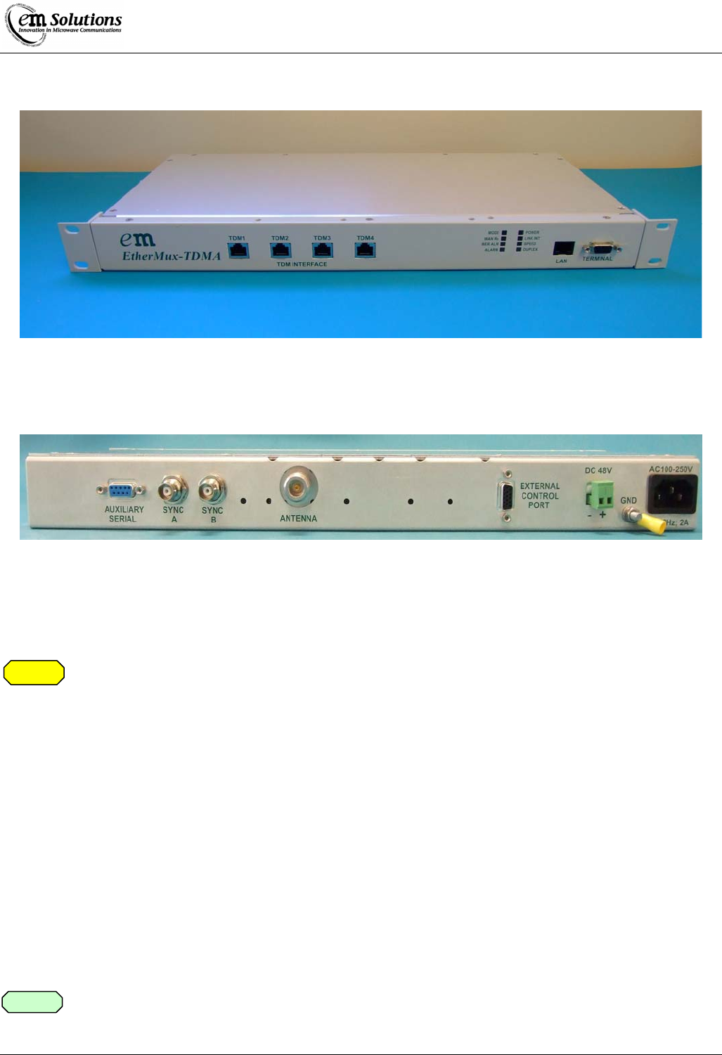
TDMA Indoor Terminal Front and Rear Panels
Front Panel Layout of EtherMux® TDMA Indoor Terminal
Rear Panel Layout of EtherMux® TDMA Indoor Terminal
Mounting the TDMA Outdoor Terminal
On sites that have other high power transmitters present, it is highly recommended that the
EtherMux® TDMA outdoor unit be located in a suitable location to prevent exposure to excessive
EMI.
1. Mount the EtherMux® TDMA outdoor Terminal onto suitable location using mounting bracket supplied.
a. Ensure that all connectors are facing down.
b. Ensure there is no major heat source near the unit.
c. If the outdoor Terminal is mounted in a cabinet in the open, ensure that the cabinet is adequately
ventilated. Especially if the cabinet is subjected to insulation.
2. Make a ground connection to the ground lug on the bottom of the Terminal.
3. Connect the antenna.
4. Use the AC Power/Ethernet/ Surge distribution box supplied to connect DC power to the outdoor terminal
via the coax cable.
Alternatively an external -48VDC (positive earth) can be used via the distribution box or directly to the
terminal.
5. Connect LAN cable.
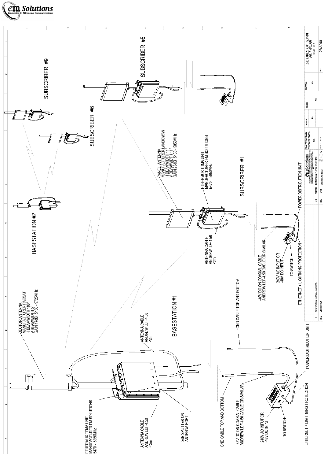
Please refer to following diagram for typical installation.
Caution
Note
EtherMux® TDMA
Version D Document Number: 0234U02 Installation & Commissioning Manual
Issue Date: 17/02/09 Page 15 of 59
EtherMux® TDMA
Version D Document Number: 0234U02 Installation & Commissioning Manual
Issue Date: 17/02/09 Page 16 of 59
Typical Installation Diagram
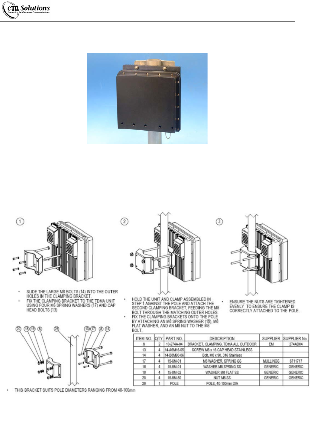
TDMA Outdoor Terminal
Mounting orientation of EtherMux® TDMA Outdoor Terminal
Mounting Bracket for the EtherMux® TDMA Outdoor Terminal
EtherMux® TDMA
Version D Document Number: 0234U02 Installation & Commissioning Manual
Issue Date: 17/02/09 Page 17 of 59
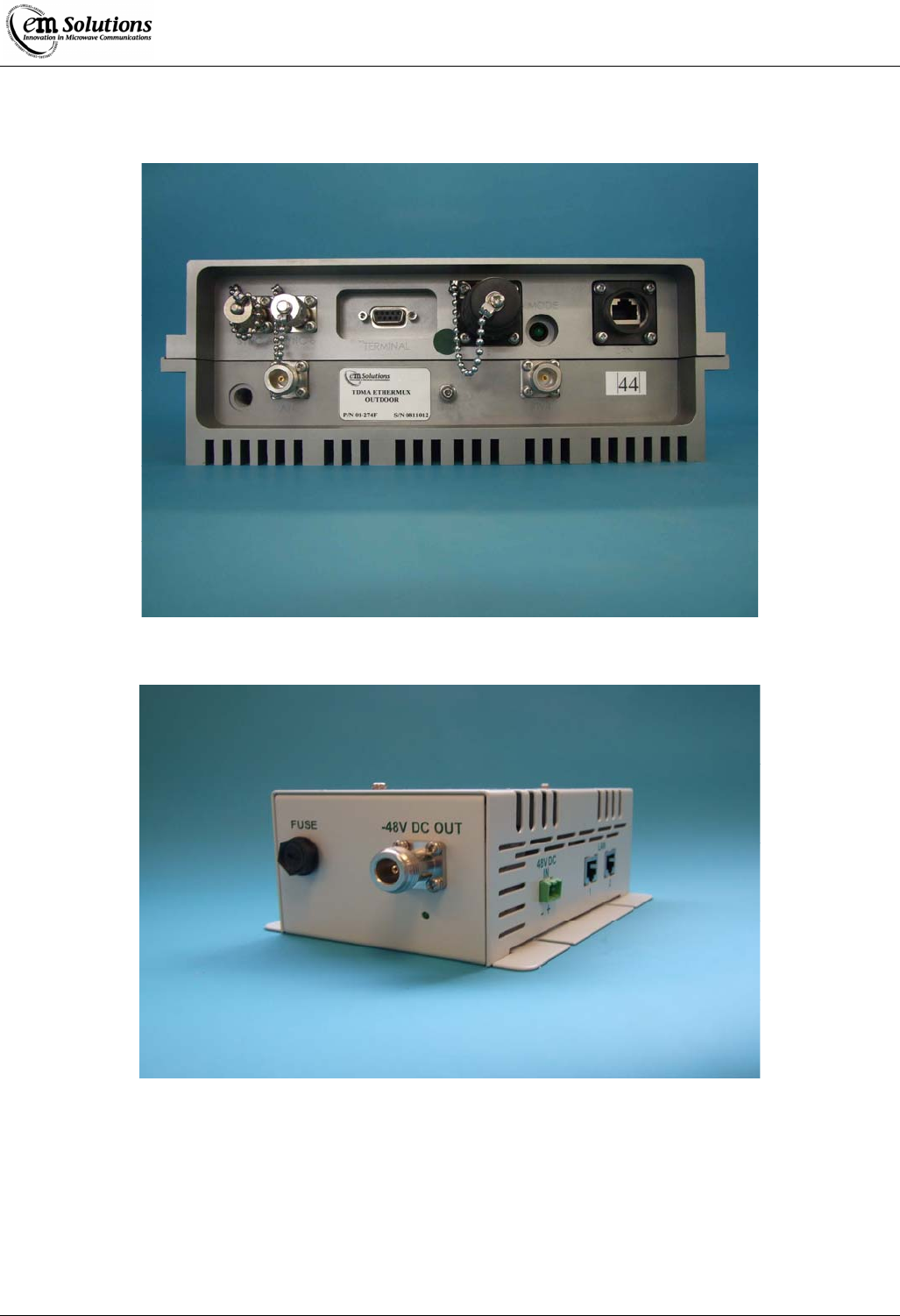
Connections to the EtherMux® TDMA Outdoor Terminal
Power/Ethernet and surge distribution box
EtherMux® TDMA
Version D Document Number: 0234U02 Installation & Commissioning Manual
Issue Date: 17/02/09 Page 18 of 59
Power/Ethernet and surge distribution box connections
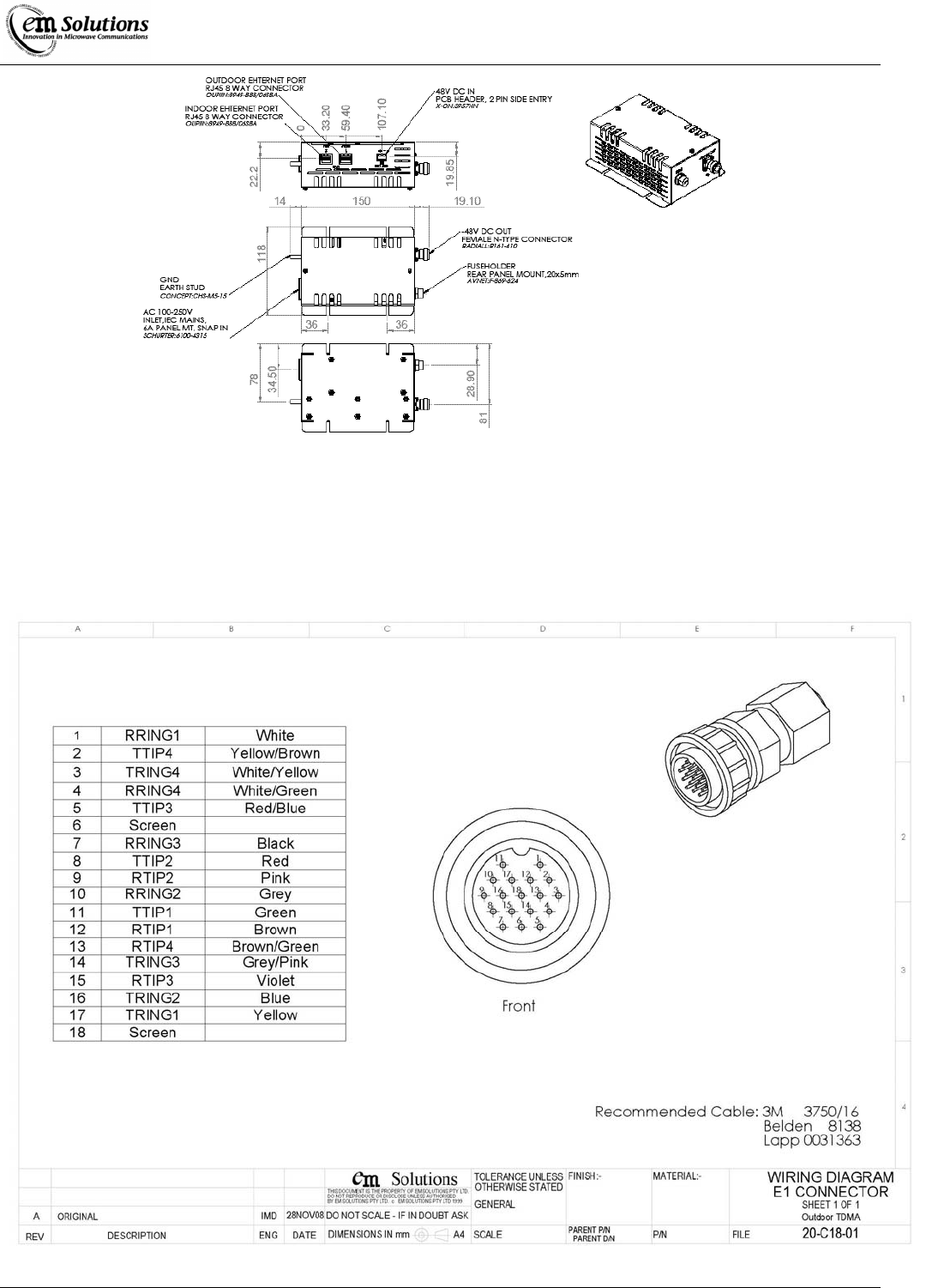
E1 Outdoor Cable Connector

EtherMux® TDMA
Version D Document Number: 0234U02 Installation & Commissioning Manual
Issue Date: 17/02/09 Page 19 of 59
Installing EtherMux® TDMA Antenna
The following are only examples and may vary depending on the particular antennas supplied.
Checking Antenna Polarisation
Verify that the antenna polarisation at both ends of the Link is the same.
1. For vertical polarisation mount gooseneck in line with the antenna grid pack with hook facing up as shown in
below.
2. For horizontal polarisation mount gooseneck and antenna grid pack have to be rotated 90° with hook either
left or right horizontal to the ground as shown below.
3. Provided the polarisation between the links is aligned to within ± 15°, then the effect of polarisation
misalignment on the received power level is not significant.
Antenna alignment
The following checks should be performed in sequence.
1. Point each Antenna in the approximate direction required. Torque the bolts that fasten the mounting bracket
to the pole, but leave all other bolts loosely connected until final alignment of the Link is completed.
2. Using visual means (eye’s, binoculars, etc), align the antenna’s as best as possible.
a. It may be helpful to use sunlight reflection of a mirror at each end to obtain the approximate direction
to point the Antenna.
b. Ensure that there are no obstructions in the line of sight path. Obstructions compromise signal quality.
3. Connect the antenna and EtherMux® TDMA Terminal together – See “Installation Instructions Section” for
details of how to do this.
4. Apply power to the TDMA Terminal.
5. Carry out the above procedures at both ends of the link.
6. The only way to monitor the receiver level is after the Terminals have achieved Lock and you are connected
to the Terminal.
7. Then adjust antenna orientation to maximise the received power at both ends.
Vertical
Polarisation
Horizontal
Polarisation
Note

EtherMux® TDMA
Version D Document Number: 0234U02 Installation & Commissioning Manual
Issue Date: 17/02/09 Page 20 of 59
Commissioning the EtherMux® TDMA Network
What You Will Need to Commission the EtherMux® Network
The following items are needed to perform Link commissioning:
1. Laptop with 100 Base-T port
2. Ethernet cross-over cable
How to Commissioning the Radio Network
Commissioning normally follows the following process:
1. Pre-configure terminals in workshop
2. Install Basestation and turn on power.
3. For each Subscriber
• Install Subscriber and turn on power.
• Adjust antenna alignment, if required.
• Confirm connection to Basestation
4. Confirm network performs as expected.
Before starting this process, ensure that you have a network plan, or summary, containing the following information:
z Configuration settings for each terminal
z Compass bearings for each antenna
z Expected transmit and receive powers
The commissioning steps are explained in the following sections.
Pre-configuring terminals in workshop
Refer to section “Basic Configuration of the EtherMux® TDMA Terminals”
Base Station Installation
1. Install the Basestation terminal, antenna(s) and RF cabling. Figure 1 illustrates a typical installation.
2. Align antenna(s) using compass and spirit-level
3. Apply power to Basestation.
4. Confirm that the Basestation is operating by observing the Mode LED. After the boot sequence completes, the Mode
LED should flash at a moderate rate.
5. [Optional step] Connect a laptop to the Basestation and confirm its configuration.
Subscriber Installation
1. Install the Subscriber terminal, antenna(s) and RF cabling. Figure 1 illustrates a typical installation.
2. Align antenna using compass and spirit-level
3. Apply power to Subscriber.
4. Observe the Mode LED. After the boot sequence completes, the Mode LED should flash at a moderate rate, to
indicate it is trying to connect to the Basestation.
5. The Mode LED should flash slowly once the Subscriber has successfully connected to the Basestation. If this doesn't
happen, please consult the Trouble Shooting section “Subscriber doesn't connect.”
6. View the Subscriber's “Status” web page. Check that
• Link Status reports “Connected to Basestation”
• RX Power estimate agrees with expected receive power.
7. Align antenna(s) if RX power is too low.
8. Confirm connection to Basestation by browsing the webpage of the Basestation. Do this by typing the Basestation's
IP address into your browser's address window.
EtherMux® TDMA
Version D Document Number: 0234U02 Installation & Commissioning Manual
Issue Date: 17/02/09 Page 21 of 59
Confirming Network Performance
Network performance testing is highly dependant on the type and complexity of the network. In general, it contains the
following steps:
z Confirm all Subscribers are connected at the expected modulation
z Confirm all transmit and receive powers are close to the expected powers.
z Connect a host to the Basestation and try to ping all Subscribers to confirm connectivity and check latency.
z Check capacity to each subscriber using specialist test equipment or software. Note that throughput on a single TCP
connection (eg whilst performing a file transfer) may be limited by TCP window size and latency.
Figure 1.
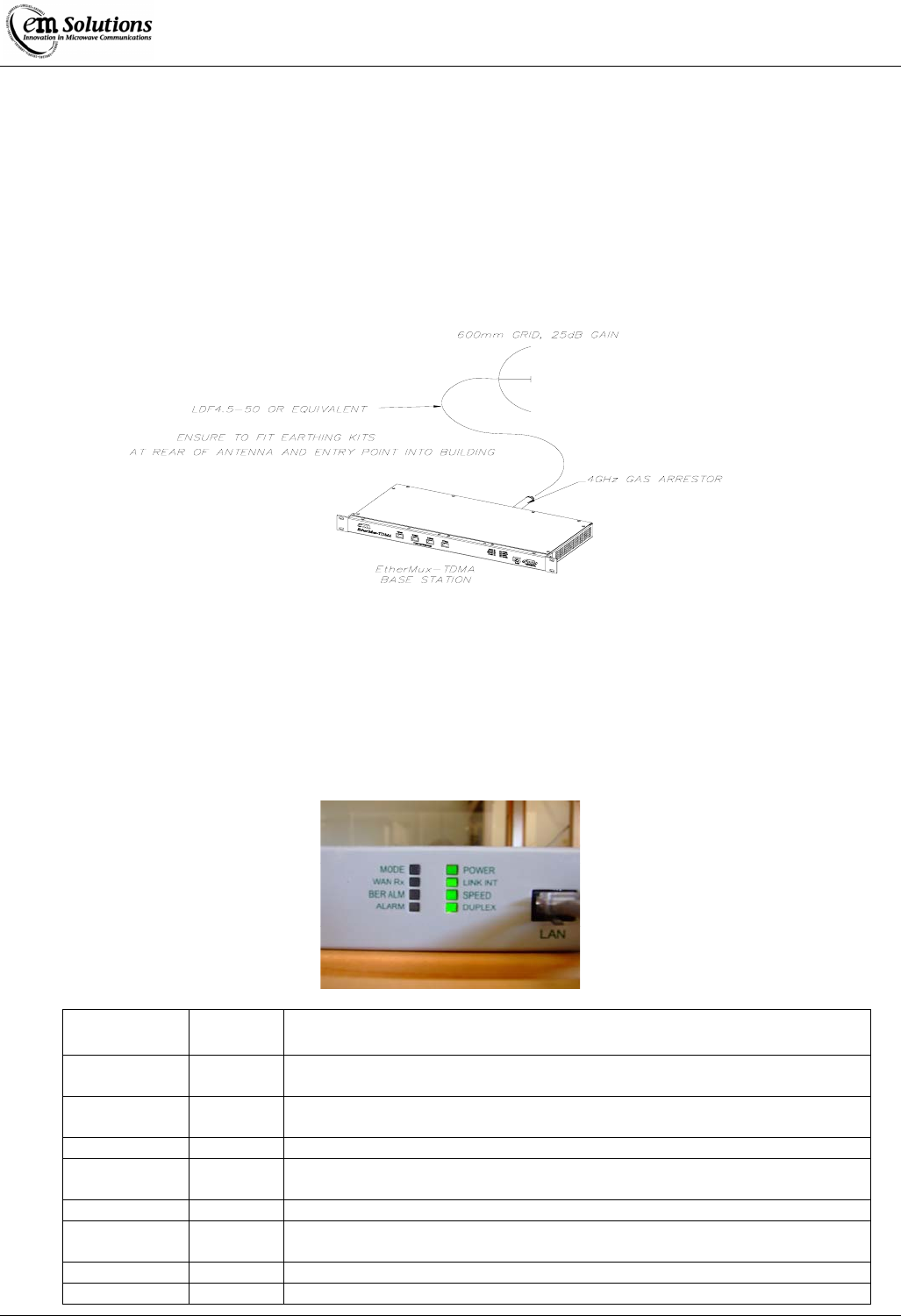
TDMA Terminal Front Panel Display
The front panel LED display of the TDMA terminal presents a summary of the link’s status. The LEDs are arranged in
two columns. At power-up most of the LEDs illuminate for a few seconds as the EtherMux® TDMA configures itself.
LED Name Colour Meaning when illuminated
Mode Green When rebooting flashes fast
Flashes slow when Link is in normal operation
WAN Rx Orange Indicates Ethernet data is being received across the radio from the remote end of
the link.
BER Alarm Red Indicates that the bit error rate (BER) across the link is exceeding 10E-6.
Alarm Red Indicates that there is, or might soon be, a problem with the link that will affect
its performance.
Power Green Indicates that the power supply is connected
Link Integrity Green Indicates a 100Base-TX Ethernet connection to the Data Port of the EtherMux®
TDMA.
SPEED Green Indicates 100Mb/s
DUPLEX Green Indicates Full Duplex.

EtherMux® TDMA
Version D Document Number: 0234U02 Installation & Commissioning Manual
Issue Date: 17/02/09 Page 22 of 59
Connecting to the EtherMux® TDMA Terminal
What You Will Need
The following items are needed when connecting to the Terminal.
1. Laptop with 100 Base-T port
2. Ethernet cross-over cable
It is advised that the configuration of the EtherMux® TDMA terminals should be done in the factory
prior to installation.
Configuring your PC
Configuring the EtherMux® TDMA Terminal involves using the Web Browser of your PC to connect to the web interface on
the EtherMux® TDMA.
The EtherMux® TDMA Terminal ships with the following initial settings of:
• IP Address: 10.0.0.254
• Subnet Mask: 255.255.255.0
• User Name: install
• Password: %!install
In order to initially access the Web Interface, you will need to configure the IP address of your PC to an address on this subnet.
The address 10.0.0.1 is probably a good choice, however any unused address on that subnet will do.
The following section explains how to set a static IP address for Windows XP. Follow a similar process for other operating
systems.
If the IP Address is unknown it can be read via the serial port on reboot using Hyper Terminal.
Open a Hyper Terminal session and connect to the serial port of the EtherMux® TDMA Terminal.
Use the following settings.
Bits per Second - 115200
Data Bits - 8
Parity - None
Stop Bits - 1
Flow Control - None
Windows XP: Setting a static IP address
To set a static IP address:
1. Open Windows Start menu.
2. Open Control Panel.
3. Classic view: Open Network Connections
Category view: Select Network and Internet Connections, and then Network Connections.
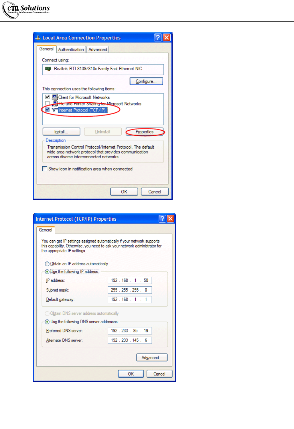
4. Double-click on your active LAN or Internet connection.
5. Click Properties.
This opens the Local Area Connections Properties window.
Note
Note
EtherMux® TDMA
Version D Document Number: 0234U02 Installation & Commissioning Manual
Issue Date: 17/02/09 Page 23 of 59
In the General tab, highlight the Internet Protocol (TCP/IP) item, and click Properties.
This opens the Internet Protocol (TCP/IP) Properties window.
7. In the General tab, click Use the following IP address, and enter:
• IP address. 10.0.0.1 (or the other address you chose)
• Subnet mask. 255.255.255.0
• Default gateway. Leave blank, or set to 10.0.0.254
EtherMux® TDMA
Version D Document Number: 0234U02 Installation & Commissioning Manual
Issue Date: 17/02/09 Page 24 of 59
8. Click OK.
9. Click OK to close each window.
Ensure that the EtherMux® TDMA Terminal is powered on and connected to the same network as your PC, either directly via
an Ethernet cross-over cable, or via a switch or hub.
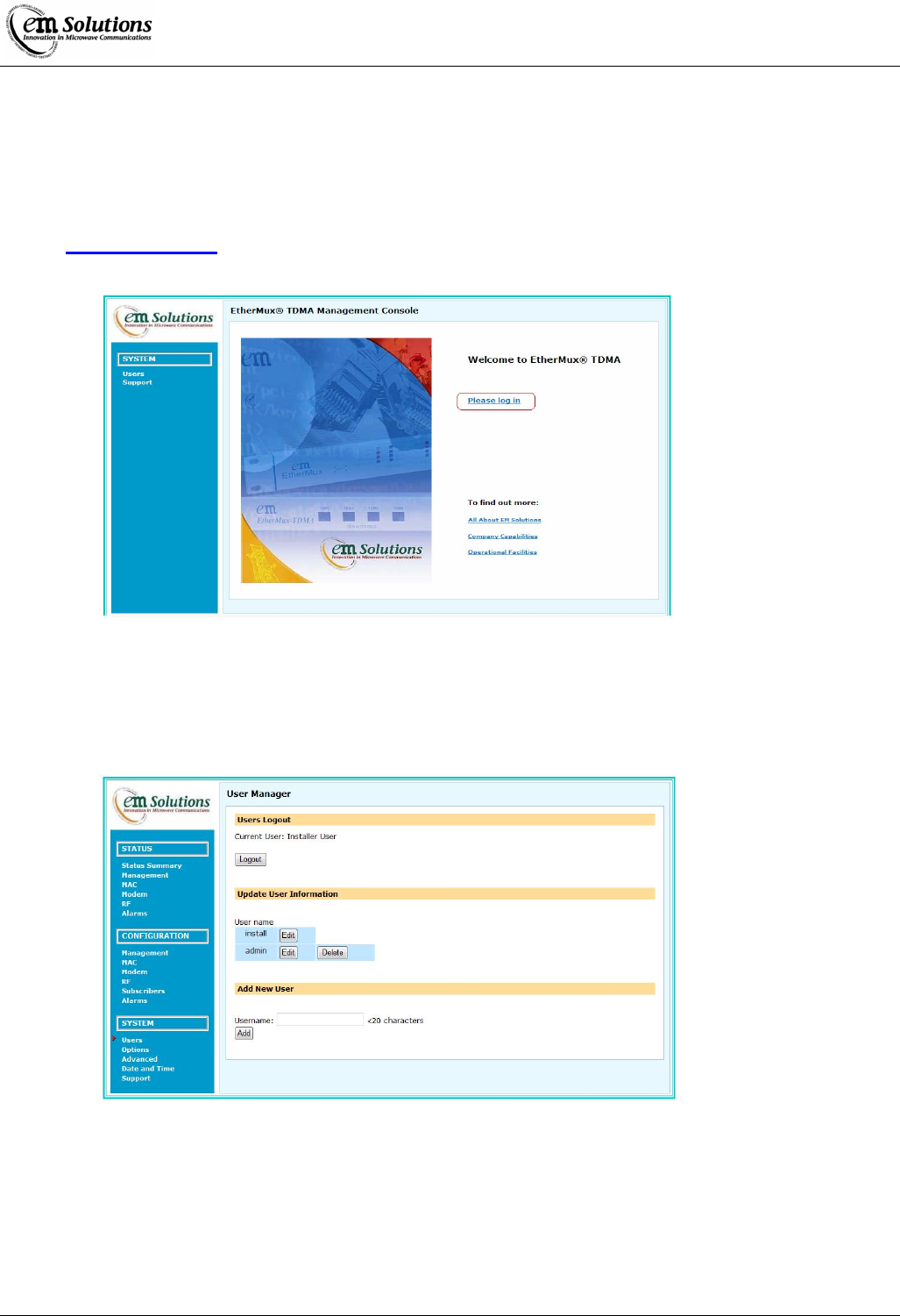
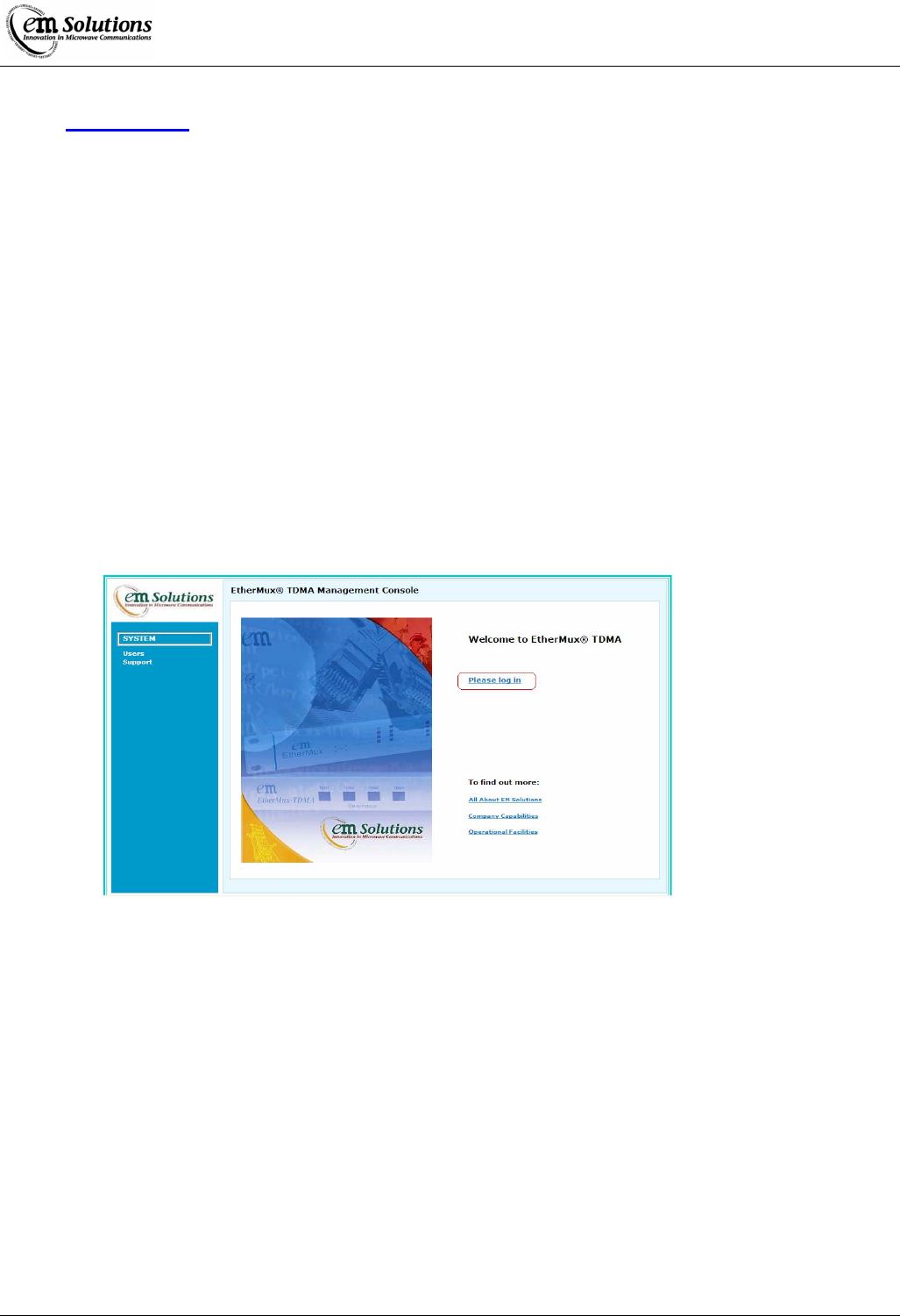
Open your web browser and type the following into the address bar:
http://10.0.0.254/
You should be presented with the following web page and click on ‘Please log in’.
Configure IP Address and Password
First you will need to set a new password for the install user.
1. Select the Users option from the SYSTEM menu on the left.
2. Enter ‘install’ as the Username and ‘%!install’ as the password and press Login.
3. You will be presented with the following screen:
4. Press Edit beside the user name ‘install’.
5. Enter a new password (twice) for the install user and press Submit.
6. Now press Logout and login again as ‘install’ with the new password.
Next you will need to set the new IP address.
1. Select the Management option from the CONFIGURATION menu on the left.
2. Enter the new IP Address, Subnet Mask and Default Gateway and press Update All.
3. Confirm that you want to do this by pressing OK at the popup.
4. The new IP address takes effect immediately, so you will need to reset the IP address on your PC to be on the same
network as the device. Follow the procedure above to do this.
EtherMux® TDMA
Version D Document Number: 0234U02 Installation & Commissioning Manual
Issue Date: 17/02/09 Page 25 of 59
Once you have done this, you can reconnect to the EtherMux®-TDMA device with your web browser by once again typing the
following into the address bar:
http://w.x.y.z/
Where w.x.y.z is the new IP address you assigned to the device.
At this point you are ready to fully configure the device.
Web Based Management
The EtherMux®-TDMA is a sophisticated device with a large number of configuration settings and status variables.
In order to provide access to these settings and status, as well as features such as configuration backup/restore and firmware
upgrades, the EtherMux®-TDMA presents a Web-based management interface.
This web interface is accessible from any network-connected computer running a modern web browser such as Internet
Explorer, Firefox or Safari.
Connecting to the Web Interface
The EtherMux®-TDMA device should be configured according to (see connecting to the EtherMux® TDMA Terminal).
Assuming that the IP address of the device is x.y.z.w, connect to the Web (Refer “Connecting to the EtherMux® TDMA
Terminal”) Interface by pointing your web browser to http://x.y.z.w/
You will be presented with the following page from which you can login.
Logging In
Log in from the Users page under the System menu section.
Unless another user has been created, login as either install or admin.
See the Quick Install Guide for default passwords.
You will be logged out if either the device reboots, or after 30 minutes of inactivity.
Navigating the Web Interface
The User Interfaces is divided into three main sections.
• Menus are on the left of the page, divided into three broad categories of Status, Configuration and System.
• Tabs across the top of the page (some menu items have only a single tab)
• The page contents showing status and/or configuration details.

EtherMux® TDMA
Version D Document Number: 0234U02 Installation & Commissioning Manual
Issue Date: 17/02/09 Page 26 of 59
The Status section provides access to the current device status and read-only configuration.
The Configuration section provides access to the current device configuration which may be modified. The install user has
access to all pages, while the admin user has access only to the network-related pages.
The System section provides access to configuration and status related to the user interface as well as configuration upload and
download, firmware upgrade and support information.

EtherMux® TDMA
Version D Document Number: 0234U02 Installation & Commissioning Manual
Issue Date: 17/02/09 Page 27 of 59
Basestation: Per-Subscriber Status
On the Basestation, various status values are specific to a particular subscriber. Where this is the case, the subscriber may be
selected via the 'Display SS' selection at the top of the page.
Status fields which are per-subscriber are identified with the current subscriber, such as (SS00).
Statistics and Counters
Various statistics and counters are maintained by the device. These include error counts, packet and byte counts and alarms.
These counts and statistics can be reset/cleared to zero with either the Clear All button to clear all fields in a section, or the
individual Clear buttons.
Updating Configuration
Configuration changes may be made by modifying text fields or selecting new values from field drop-downs.
To update a single field, use the Update button, while to update all fields in a section, use the Update All button.
Some changes require a reboot, and a popup will be displayed to indicate this.
Users
The EtherMux®-TDMA supports the creation of administrative users with different access levels.
Users are managed from the SYSTEM -> Users page.
Here users may be added, deleted or modified.
Be careful not to lose the username and password of the install user.
User Levels
There are 3 user access levels.
Standard permission
• A user with this access level may access the device status, but may not modify the device in any way.
Admin permission
A user with this access level may access the device status as well as modify a limited set of configuration
setting. This includes network, alarm and SNMP settings.
Installer permission
• A user with this access level may access the device status and change any configuration settings.
• This user may also upgrade the device firmware as well as download and upload configuration settings.
Auto Refresh
It is possible to enable auto refresh on status pages.
Navigate to SYSTEM-> Options -> Web Config where auto refresh can be enabled and the refresh interval can be set.
When this option is enabled, the web browser will automatically refresh status pages at the specified interval.
Note
Note
Note

EtherMux® TDMA
Version D Document Number: 0234U02 Installation & Commissioning Manual
Issue Date: 17/02/09 Page 28 of 59
Modem Variables
Status-Modem Variables Units Description
Modem Type Number Hardware configuration number used to identify the modem board. It is read
directly from the modem board.
TDMA Modem S/N Serial number of TDMA modem board
Channel Bandwidth Operating channel width
Uplink Modn Current Current uplink modulation
Downlink Modn Current Current downlink modulation
Uplink Capacity Aggregate Measures the total capacity of the link from the basestation to the subscriber. It
counts all allocations including the maps, channel descriptors and broadcast
data.
Downlink Capacity Aggregate Total capacity allocated on the uplink. It is simply the total of all subscriber
allocations.
Uplink Capacity Measures the bandwidth allocated to a particular subscriber on the downlink.
Downlink Capacity Measures the bandwidth allocated to a particular subscriber on the uplink.
FPGA Temp mV Voltage measured from the temperature sensing diode in the FPGA.
XCF Amplitude Amplitude of cross-correlation peak in preamble processing.
CINR dB Signal Quality
CINR Max (short) dB Max Signal Quality (600 secs)
CINR Min (short) dB Min Signal Quality (600 secs)
VCXO Voltage mV Control voltage applied to reference oscillator (VCXO). In the basestation,
this is a fixed voltage. In the subscriber, this is adjusted to make the
subscriber's reference oscillator track the basestation's.
BER (15 sec) Bit error rate measured over the last 15 seconds.
PER (15 sec) Packet error rate measured over the last 15 seconds.
Errors Total Total number of errors detected in data received across radio. This includes
errors in headers, data and padding.
RS Errors Total Only visible to installer
Preambles Total Total number of preambles detected. It is the same as the total number of rf
bursts detected from other EtherMux®-TDMA terminals operating on the
same frequency. In normal operation, this will increase at the frame rate. For
example, if the frame rate is 5 ms, this number should increase by 200 every
second.
PHY RX kbytes Total Total number of bytes received across radio. Includes headers, data and
padding.
TX Burst Count Total number of bursts transmitted by terminal
Frame Count Total number of TDD frames counted. This should increase at the frame rate.
Modem +12V mV +12 V supply rail of modem board
Modem +3.3V mV +3.3 V supply rail of modem board
Modem +2.5V mV +2.5 V supply rail of modem board
Modem +1.2V mV +1.2 V supply rail of modem board
Configuration-Modem Variables Units Description
Channel Bandwidth MHz Selects the channel bandwidth. The terminal must be rebooted for this to take
effect. The available channel widths vary for different EtherMux®-TDMA
model numbers.
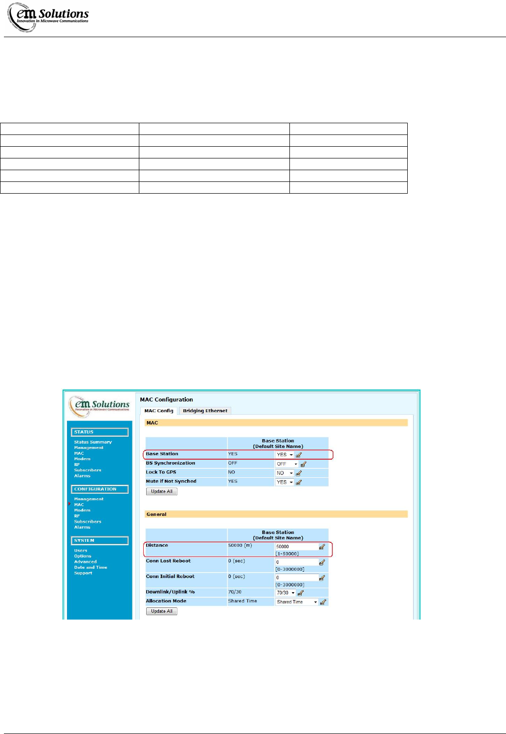
EtherMux® TDMA
Version D Document Number: 0234U02 Installation & Commissioning Manual
Issue Date: 17/02/09 Page 29 of 59
Basic Configuration of the EtherMux® TDMA Terminals
Configuring the Base Station
To configure the base station, a list of basic parameters needs to be configured.
Parameter Default Value Group
Base Station YES MAC
Distance 50000 MAC
Channel Bandwidth 7 Modem
RF Frequency 3700 (or 5800) RF
Site Name Default – Site Management
Steps to configure the base station:
Log in as “install” user
Refer “Connecting to the EtherMux® TDMA Terminal”
Configure MAC
• Select the MAC Option from the CONFIGURATION menu on the left
• Select YES from the Base Station drop down box
• Enter the distance with some margin to the furthest most Subscriber in the Distance text box
• Click Update All
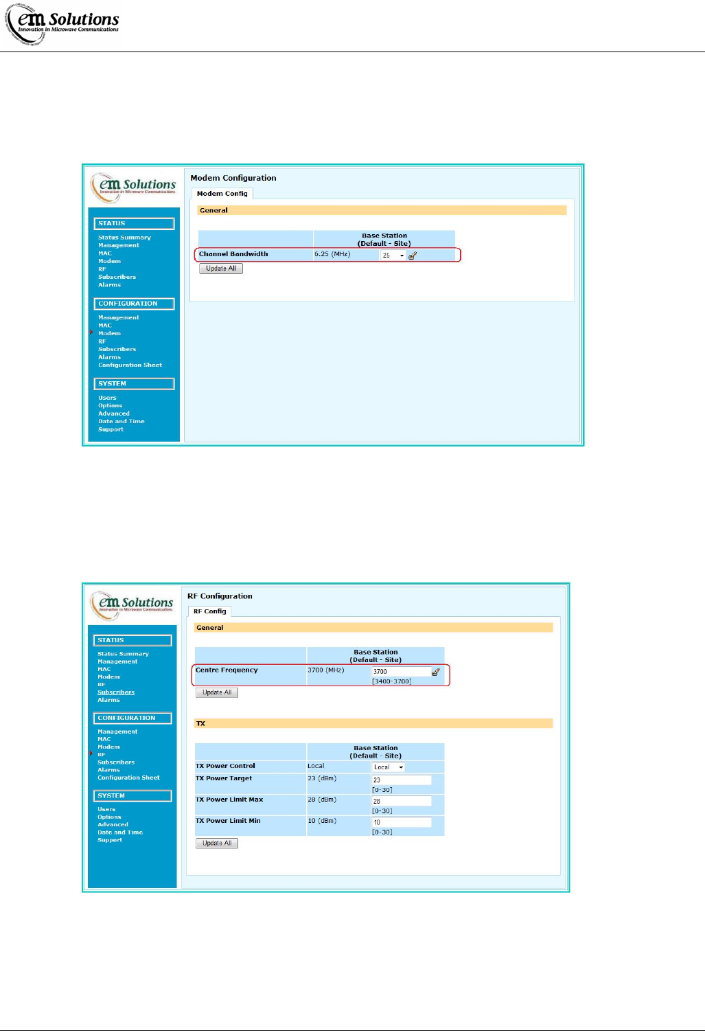
EtherMux® TDMA
Version D Document Number: 0234U02 Installation & Commissioning Manual
Issue Date: 17/02/09 Page 30 of 59
Configure Channel Bandwidth
• Select the Modem Option from the CONFIGURATION menu on the left
• Select the channel bandwidth from the drop down list
• Click Update All
Configure RF Frequency
• Select the RF Option from the CONFIGURATION menu on the left
• Enter the Frequency into the Centre Frequency text box
• Click Update All
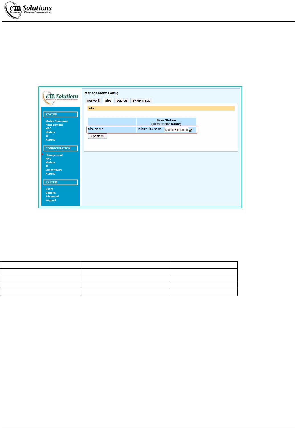
EtherMux® TDMA
Version D Document Number: 0234U02 Installation & Commissioning Manual
Issue Date: 17/02/09 Page 31 of 59
Configure Site Settings
• Select the Management Option from the CONFIGURATION menu on the left
• Select Device Tab in the Management Configuration window
• Enter the Site Name of the device
• Click Update All
Configuring the Subscriber Station
To configure the subscriber station, a list of basic parameters needs to be configured.
Parameter Default Value Group
Base Station NO MAC
Channel Bandwidth 7 Modem
RF Frequency 3750 (or 5800) RF
Site Name Default – Site Management
To configure the subscriber station:
Log in as “installer” user
Refer section “Connecting to the EtherMux® TDMA Terminal”
Configure MAC
• Select the MAC Option from the CONFIGURATION menu on the left
• Select NO from the Base Station drop down box
• Click Update All
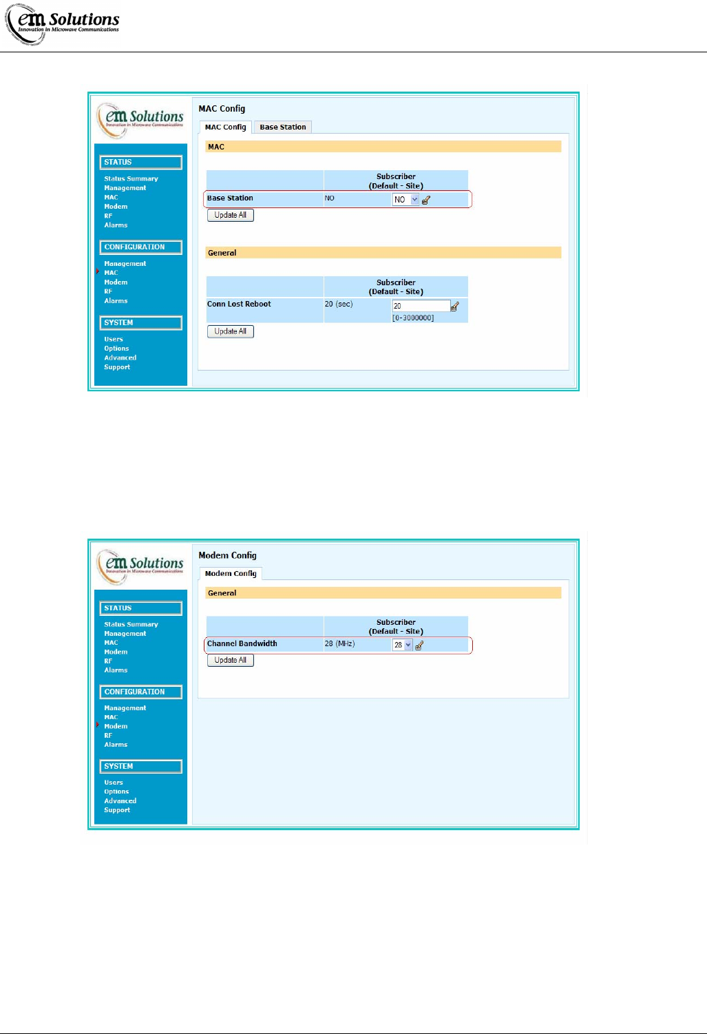
EtherMux® TDMA
Version D Document Number: 0234U02 Installation & Commissioning Manual
Issue Date: 17/02/09 Page 32 of 59
Configure Channel Bandwidth
• Select the Modem Option from the CONFIGURATION menu on the left
• Select the channel bandwidth from the drop down list
• Click Update All
Configure RF Frequency
• Select the RF Option from the CONFIGURATION menu on the left
• Enter the Frequency into the Centre Frequency text box
• Click Update All
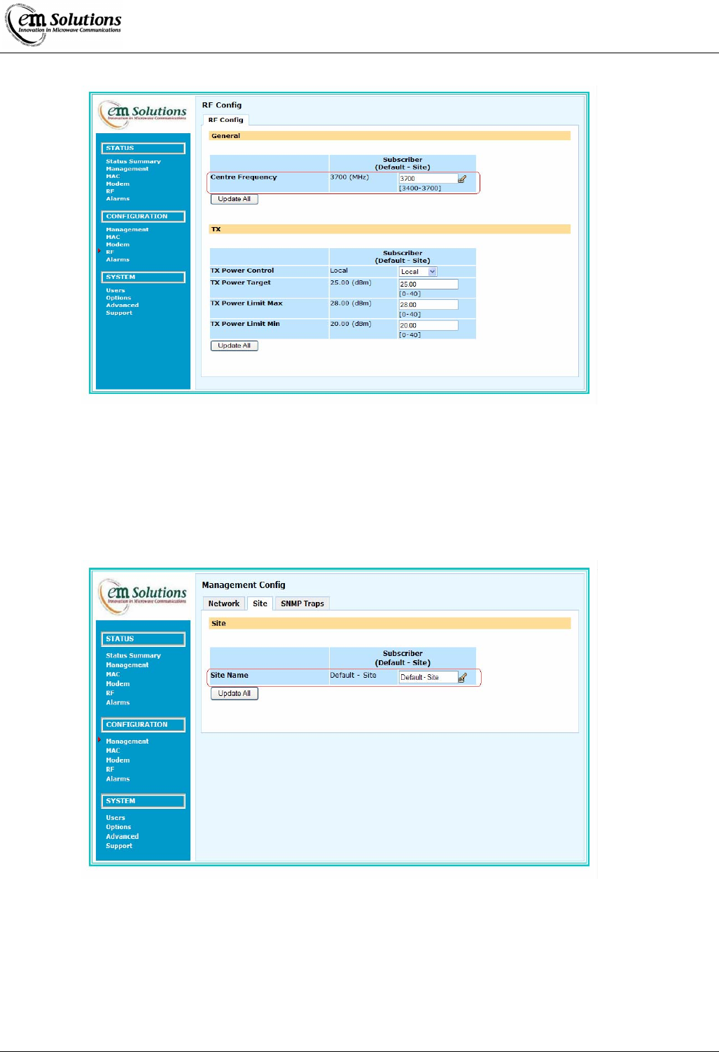
EtherMux® TDMA
Version D Document Number: 0234U02 Installation & Commissioning Manual
Issue Date: 17/02/09 Page 33 of 59
Configure Site Settings
• Select the Management Option from the CONFIGURATION menu on the left
• Select Device Tab in the Management Config window
• Enter the Site Name of the device
• Click Update All
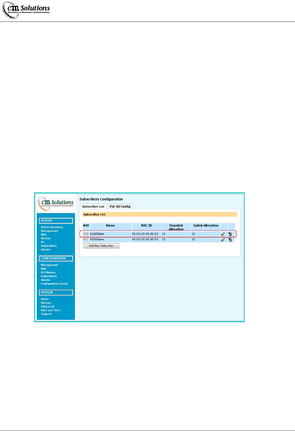
EtherMux® TDMA
Version D Document Number: 0234U02 Installation & Commissioning Manual
Issue Date: 17/02/09 Page 34 of 59
Basestation Configuration – Adding Subscribers
The Basestation must be configured with a list of Subscribers that are allowed to connect. Each subscriber is uniquely
identified by its MAC ID.
To configure allowed subscribers:
• Click on Subscribers in the configuration section of the navigation panel (on the left).
• Click on the Subscribers list tab.
• Add a new subscriber by filling in the entry items under Add New Subscriber.
o Enter the Subscriber’s Name
o Enter the Subscriber’s MAC ID
o Select the downlink and uplink allocation settings.
o Click Add New.
The Downlink Allocation and Uplink Allocation fields are used to distribute up/downlink times to the subscribers. These
fields can be set to any number between 1 and 20. For any two subscribers, the ratio of these numbers gives the relative
allocated up/downlink times. For example:
• Setting all subscribers to 10, results in all subscribers receiving equal time to transmit.
• Consider a three subscriber network. Setting subscriber1=5, subscriber2=10 and subscriber3=20, would result in
subscriber2 getting twice as much time as subscriber1, and subscriber3 getting twice as much time as subscriber2

EtherMux® TDMA
Version D Document Number: 0234U02 Installation & Commissioning Manual
Issue Date: 17/02/09 Page 35 of 59
Configuration Backup
The EtherMux®-TDMA is a highly configurable device. As such, many configuration settings may be modified and stored on
the device. The EtherMux®-TDMA allows these configurations to be downloaded and saved, and then later restored either to
the same device or to a replacement device.
Why take configuration backups?
There are two general reasons to make configuration backups.
• To allow a previous configuration to be restored in the event of an incorrect change.
• To configure a replacement device in the event that a device needs to be swapped out.
Downloading a configuration backup
To download the current device configuration as a backup file, simply navigate to
Advanced->System Config in the web interface and press the Download button under Config Download.
A backup file will be downloaded to your computer named something like config_downloaded.tar.bz2
This file can be renamed as required, however the .tar.bz2 extension should be retained.
Restoring a previously downloaded configuration backup
This will overwrite all of the current setting on the device, including the IP address.
Please ensure that the appropriate configuration backup file is selected.
Navigate to Advanced->System Config in the web interface.
Select a previous configuration backup file for the 'Select Upload Package' field and press Upload.
The configuration on the device will then be updated to match the uploaded configuration backup file.
At this point, a reboot will typically be required for the configuration changes to take effect, so navigate to Advanced->Reboot
and press Reboot to reboot the device.
What settings are included in the backup?
The following settings are included in the configuration backup:
• Management/Networking settings
• MAC settings
• Modem settings
• RF settings
• Alarm settings
• Username/password settings
When replacing an existing (perhaps failed) device, then new device will have a different mac ID than
the previous device. The configuration of other devices in the link may need to be updated to reflect
the new mac ID.
Restoring factory default settings
It is also possible to restore a device to factory default settings. In this case all settings except for network settings will be
erased and reset to defaults.
This includes:
• Station: Basestation
• Centre Frequency: 3662.5MHz
• Channel Bandwidth: 6.25MHz
The device will need to be completely reconfigured after this step.
In particular, the mac ID list in the basestation would have to be updated.
Navigate to Advanced->System Config in the web interface and press the Restore Default button.
Caution
Caution

EtherMux® TDMA
Version D Document Number: 0234U02 Installation & Commissioning Manual
Issue Date: 17/02/09 Page 36 of 59
Subscribers
In any installation, there is a single basestation and one or more subscribers connecting to it. Access to the network is granted
to a subscriber via the Subscriber configuration within the basestation.
The basestation maintains a list of subscribers which are allowed to access the network in the Subscriber List under the
Subscribers Configuration. A subscriber is uniquely identified by its MAC ID.
Through this list the user is able to add, delete or modify subscriber parameters.
Adding a new subscriber is done by clicking the Add New Subscriber Button on the web interface. Clicking this button brings
up a page where the user is able to enter a Name, MAC ID, Downlink Allocation and Uplink Allocation for the subscriber.
The MAC ID should be exactly the address provided with the subscriber.
The Downlink Allocation and Uplink allocation are ratio based values relative to other subscribers in the network. For example
a subscriber with an allocation of 20 will get twice the allocation of a subscriber with an allocation of 10.
The change button and garbage bin button are used to modify a subscriber's settings and delete a subscriber respectively.
The Per-SS Configuration page allows the user to configure advanced parameters for each subscriber individually.
For this configuration the user selects which subscriber to display from the Display SS pulldown box and presses select.
The Modem configuration options
• Uplink Adapt Mode - sets whether to have a fixed, capped or adaptive modulation on the uplink.
• Uplink Modulation (for fixed and capped modes only) - sets which modulation to use for the uplink.
• Downlink Adapt Mode - sets whether to have a fixed, capped or adaptive modulation on the downlink.
• Downlink Modulation (for fixed and capped modes only) - sets which modulation to use for the downlink.
The RF configuration option
• RX Power Target - sets the target receive power for the basestation to be receiving from that particular subscriber in
dBm.
Configuration
All subscribers configuration is contained within the Subscribers section of the Configuration area.
• Subscriber List
This is the list of the subscribers allowed to access the network.
Up to 16 subscribers may be defined and are uniquely identified by their MAC ID.
The uplink and downlink allocation for each subscriber is relative, ie a subscriber with an allocation of 20 will have double the
allocation of a subscriber with an allocation of 10.
• Per-SS Config
This is where the user is able to set advanced parameters for each subscriber.
The user selects a subscriber in the Display SS pulldown box and presses select.
The modem parameters that are configurable are the adapt mode and modulation configuration (independently for the uplink
and downlink).
In all installations unless special circumstances exist it is recommended that the mode be set to Automatic for both uplink and
downlink.
• Fixed Adaption Mode
This means that the subscriber will always transmit (for uplink) or receive (for downlink) at the modulation type specified in
the modulation configuration entry. This may be useful in paths where conditions may caused rapid fluctuations in signal
quality.
• Capped Adaption Mode
This means that the subscriber will always transmit or receive at the modulation specified in the modulation configuration or a
more robust one.
• Automatic Adaption Mode
This means that the modulation transmitted or received by the subscriber will be determined by the signal quality / strength
through communications between the basestation and subscriber. This is the recommended setting.

EtherMux® TDMA
Version D Document Number: 0234U02 Installation & Commissioning Manual
Issue Date: 17/02/09 Page 37 of 59
The Modulation Configuration is separately settable for the uplink and downlink for the Fixed and Capped modes only. The
pulldown list is sorted in order from most robust (ie lowest bit rate / highest interference protection) to least robust modulation.
The RF configuration allows the user to select what power the signal being transmitted to the basestation should arrive at. This
is useful to prevent interference between installations by allowing incoming powers to be roughly at the same level.
Transmit Power Control
The transmit power may be controlled in one of three ways on a subscriber unit or one of two ways on a basestation unit.
These options may be selected on the CONFIGURATION->MODEM/RF Menu page.
Both the subscriber and basestation support manual and local modes, while the subscriber supports remote (basestation
controlled) mode.
These modes are explained below
Local Mode
In local mode, a target power is specified. The actual transmit power is then continuously measured and small gain adjustments
are made as necessary to keep the transmit power close to the target power.
Remote Mode
Remote mode is only available for a subscriber unit. It allows the transmit power of the subscriber to be controlled by the
basestation based on the receive power at the basestation.
This mode requires configuration on both the basestation and the subscriber.
First, for the subscriber, remote mode must be selected and maximum and minimum power limits must be specified. The
maximum limit may be important to ensure that regulatory limits are not exceeded.
Next, the receive power target must be specified in the per-subscriber section on the basestation. The basestation will then
control the subscriber to ensure that receive power at the basestation is close to the receive power target, if possible given the
minimum and maximum limits specified on the subscriber.
This mode is especially recommended for a site with multiple basestations since it helps to avoid interference at the basestation
site by keeping the subscriber power only as high as necessary, but no higher.
Before the subscriber connects to the basestation, the per-subscriber target is not available. In this
case, an unconnected subscriber will transmit at a power level approximately 3dB below the
lowest receive power target configured for any subscriber.
For example, if two subscribers are configured with receive power targets of -50dBm and -53dBm, the target receive power
during initial connection will be at approximately -56dBm for all subscribers.
Manual Mode
The manual mode is the simplest mode and should not be used in normal circumstances.
The transmit attenuation level is specified directly.
For example, specifying a transmit attenuation of 10dB would result in a transmit power of approximately 22dBm on a
standard power unit.
This value will vary from unit to unit and with other factors such as temperature. Thus one of the
other modes is recommended in almost all circumstances.
Note
Note

EtherMux® TDMA
Version D Document Number: 0234U02 Installation & Commissioning Manual
Issue Date: 17/02/09 Page 38 of 59
Alarms
The EtherMux®-TDMA generates alarms for system status, link status and power status which provides the diagnostic
information of the system and gives an overview of the link performance. There are two kinds of alarms in the system: major
and minor alarms. The major alarms reflect the performance of the critical parts of the system (e.g. link status, receive power
and etc.) and the minor alarms indicate the misbehaviour of some aspects of the system having potentially negative effects on
the system performance (e.g. supply rails, LO out of lock, and etc.). The system remembers which variables have been in alarm
condition, even after the alarm condition clears. These variables are highlighted in the web interface as "latched alarms".
Latched alarms persist until cleared via the web interface.
Alarm Configuration
The alarm configuration is done by setting up the alarm rules and thresholds of monitored parameters via the web interface.
To configure alarms:
• Log in as install user
• Select the Alarms Option from the CONFIGURATION menu on the left
• Select the tab in which there is the parameter you are going to configure
• Configure the Rule, Major Enab, Minor Enab, thresholds, Trap Src
• Click the Update button at the end to commit your setting
Pre-defined Major Alarms
Parameters Rule
(ie Generate alarm when ) Thresholds Note
Inactive SSs Count Greater than >0 BS only
Terminal Synched Is Value(s) is NO BS, Lock to GPS = YES or
BS synch = SLAVE only
GPS Locked Is Value(s) Is No BS, Lock to GPS = YES
only
Active Is Value(s) Is No SS only
CINR Less than < 10
BER (15 sec) Greater than >1e-6
External Fan Failure Is Value(s) Is YES High Power only
Pre-defined Minor Alarms
Parameters Rule
(ie Generate alarm when ) Thresholds Note
BER (15 sec) Greater than >1e-8
Modem +12V Outside range > 13200; < 10800
Modem +3.3V Outside range > 3630; < 2970
Modem +3.3VX Outside range > 3630; < 2970
Modem +2.5V Outside range > 2750; < 2250
Modem +1.2V Outside range > 1320; < 1080
RF Temp Greater than > 75
IF LO Lock Is Value(s) is NO
RF LO Lock Is Value(s) is NO
RF +12V Outside range > 13200; < 10800
RF +10V Outside range >11000; <9000 High Power only
RF +8V Outside range > 9000; < 6000
RF +5V Outside range > 5500; < 4500
RF -5V Outside range > -4000; < -6000
Internal Fan Failure Is Value(s) Is YES
External Fan Failure Is Value(s) Is YES High Power only
RX Gain Overrange Not Value(s) not OK SS Only
TPC TX Power Overrange Not Value(s) not OK SS Only
TPC TX Atten Overrange Not Value(s) not OK SS Only
Alarm Summary
To view Alarm Summary:
• Log in as install user
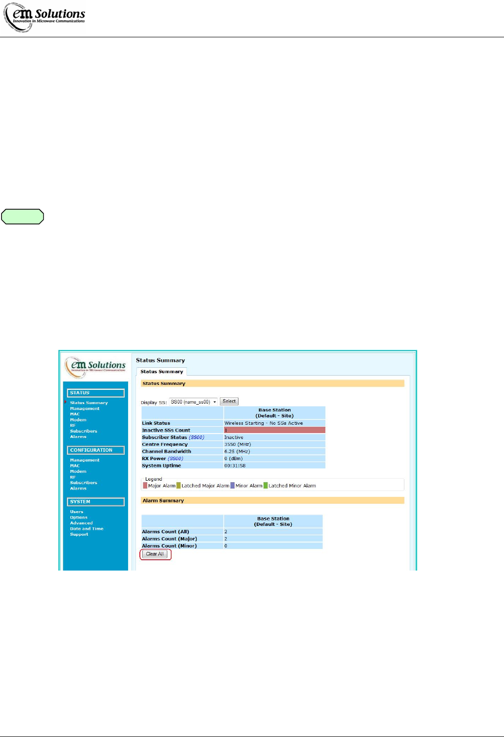
EtherMux® TDMA
Version D Document Number: 0234U02 Installation & Commissioning Manual
Issue Date: 17/02/09 Page 39 of 59
• Select Status Summary Option from the STATUS menu on the left
• The Alarm Summary on the bottom of the web page shows how many alarms have been generated
Alarm Status
To view alarm status via the web interface:
• Log in as install user
• Select the Alarms Option from the STATUS menu on the left
• Select tab All, Major or Minor to view alarm status
• Select tab Historical Log to view historical log of alarms
The alarm status is shown in different colours indicating whether the alarm is a major alarm, a latched major alarm, a minor
alarm or a latched minor alarm.
For SNMP alarm traps, refer to SNMP traps section.
Clearing Alarms
Alarms and traps can be cleared via the web interface.
To clear alarms:
• Log in as install user
• There are two ways to clear the alarms
1. Navigate to STATUS->Status Summary and click Clear All button on Alarm Summary page
2. Navigate to STATUS->Alarms->All and click Clear All button.
Note
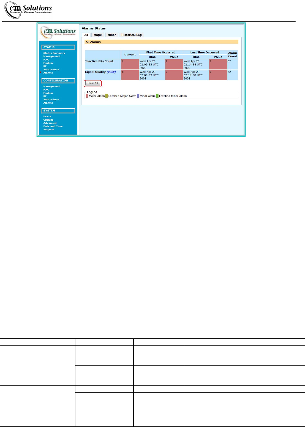
EtherMux® TDMA
Version D Document Number: 0234U02 Installation & Commissioning Manual
Issue Date: 17/02/09 Page 40 of 59
SNMP
SNMP is implemented to remotely monitor the EtherMux®-TDMA. The following SNMP features are provided:
• SNMP v1, v2c
• Standard (including mib-2, snmpV2, net-snmp) and proprietary(ETHERMUX-TDMA) MIBs
• SNMP traps v2c
The EtherMux®-TDMA MIBs define a list of objects (parameters) that reflect the performance of all aspects of the system.
Importing the MIBs to SNMP monitoring tools allows remote monitoring of the system.
SNMP traps or notification are generated after a system reboot or when an alarm condition is present.
There are no settable parameters via SNMP. The configuration of the system is done via the web interface.
Clearing alarms results the clearing of traps.
MIBs
MIBs supported:
• ETHERMUX®-TDMA
• Standard MIBs
For detailed information, refer to http://net-snmp.sourceforge.net/docs/mibs
Community String
The EtherMux®-TDMA will only respond to SNMP packets with a correct community string.
The community string for read in version 1.0 is “EMSOLUTIONS” and can’t be changed.
But in version 1.1 the community strings can be changed via CONFIGURATION->Management->SNMP->Community
Strings
SNMP Traps
The system supports the following SNMP traps
MIBs Objects OID Description
coldStart 1.3.6.1.6.3.1.1.5.1 An indication that the SNMP entity is
reinitializing itself and its configuration may
have been altered
SNMPv2-MIB
warmStart 1.3.6.1.6.3.1.1.5.2 An indication that the SNMP entity is
reinitializing itself and its configuration is
unaltered
nsNotifyStart *.8072.4.0.1 An indication that the agent has started running
nsNotifyShutDown *.8072.4.0.2 An indication that the agent is in the process of
being shut down
NET-SNMP-AGENT-MIB
nsNotifyRestart *.8072.4.0.3 An indication that the agent has been restarted
NET-SNMP-TC (snmpTrapEnterprise)
linux
*.8072.3.2.10 Sent with coldStart after reboot indicating the
Operating System of the agent

EtherMux® TDMA
Version D Document Number: 0234U02 Installation & Commissioning Manual
Issue Date: 17/02/09 Page 41 of 59
wmanPriNotifInstant
Alarms
*.10132.**.12.1.1 Instant traps
wmanPriNotifMajorA
larms
*.10132.**.12.1.2 Periodic traps
wmanPriNotifMinorA
larms
*.10132.**.12.1.3 Periodic traps
ETHERMUX-TDMA
wmanPriNotifRemind
erReset
*.10132.**.12.1.4 Reminder traps
*: 1.3.6.1.4.1, e.g. SNMPv2-SMI::enterprises
**: EtherMux®-TDMA OID = 2000 + Mib Version Number - 1
The MIB Version can be found via STATUS->Management->Device->Software->Mib Version. The Mib
Version is in the format: ETHERMUX-TDMA-Vxx.mib. (where xx: Mib Version Number).
Instant traps
• Traps are sent instantly for the specified number of times (Instant Trap Tries) at the specified time interval (Instant
Trap Interval) after the first Major Alarm is generated.
• Then no instant traps sent until users manually clear the traps.
• The trap packets contain trap OID, trap description and the object that triggered the alarm.
Periodic traps
• Traps are sent at the specified time interval (Periodic Trap Interv).
• Major alarm traps (trap OID: wmanPriNotifMajorAlarms) are generated if any latched major alarms detected.
• Minor alarm traps (trap OID: wmanPriNotifMinorAlarms) are generated if any latched minor alarms detected.
• The trap packets contain trap OID, trap description and a list of objects.
Reminder traps
• Trap sent at the specified time interval (Reminder Trap Interv) to remind users to manually clear the traps if the traps
haven’t been cleared.
• The trap packets contain trap OID and reminder message.
SNMP Configuration
1. Community Strings
• Log in as installer user
• Select the Management Option from the CONFIGURATION menu on the left
• Select tab SNMP
• Set up Read Only community string
• Click the Update or Update All button to commit your setting
2. Traps General configuration
• Log in as admin (or above) user
• Select the Management Option from the CONFIGURATION menu on the left
• Select tab SNMP
• Set up Instant Trap Interval, Instant Trap Tries, Periodic Trap Interv and Reminder Trap Interv
• Click the Update or Update All button to commit your setting
Note
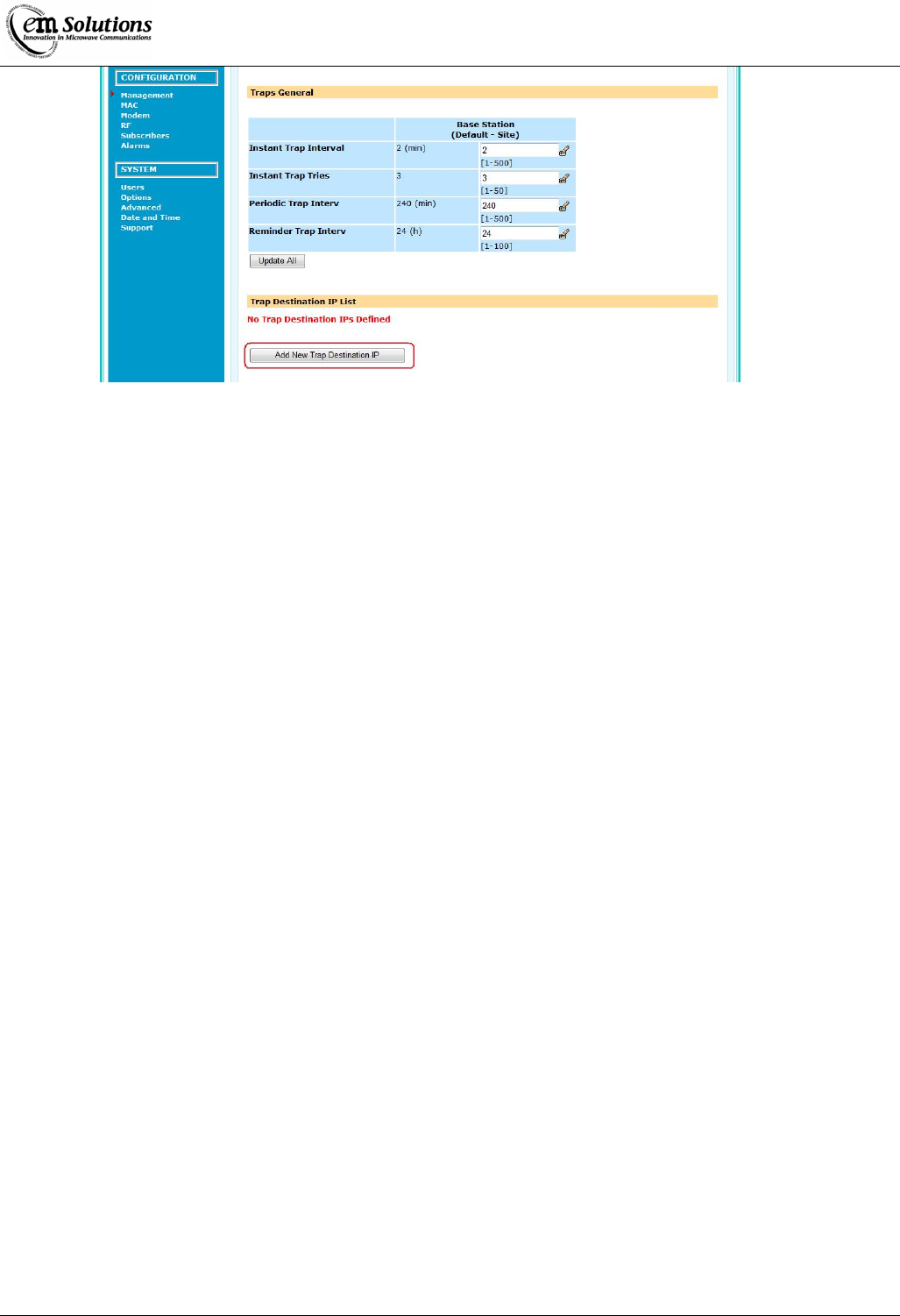
EtherMux® TDMA
Version D Document Number: 0234U02 Installation & Commissioning Manual
Issue Date: 17/02/09 Page 42 of 59
3. Trap Destination IP configuration
• Log in as admin (or above) user
• Select the Management Option from the CONFIGURATION menu on the left
• Select tab SNMP Traps
• In the Trap Destination IP List page, click Add New Trap Destination IP button to add a new IP or click the
Delete button to delete an existing IP.

EtherMux® TDMA
Version D Document Number: 0234U02 Installation & Commissioning Manual
Issue Date: 17/02/09 Page 43 of 59
Traffic Management
Overview
Bridging ethernet is a layer-2 network interface available for the user to allow ethernet networks to be set up using the
EtherMux®-TDMA units. Bridging ethernet effectively turns the ports of the EtherMux® devices within a single system to
behave like a switch.
In keeping with switch operation, there is minimal configuration required to get the system working.
Note that while called bridging ethernet, this system is not an 802.1D bridge and doesn't implement protocols such as
spanning-tree.
The configuration of the bridging ethernet occurs only at the basestation at a system wide level and requires installer
privileges. In all installations, the default configuration is recommended except for an ISP mode, where the Retransmit
parameter may be disabled to isolate subscribers from one another. For further details please see the configuration section
within this chapter. This section has a brief introduction to the configuration options that are present, but refer to the
configuration section for further details on the options.
There are three configuration options which are used to filter the addresses going through the network: Broadcast, Multicast
and Private Addresses. The disabling of any of these options will cause the bridging ethernet to filter out the respective MAC
ID type (ie not allow it to go over the link). This is rarely done in practise, but in some networking situations it may be useful.
The bridging ethernet is able to generate 802.3x MAC Pause control frames in order to allow flow control to prevent packet
loss when there is a rate mismatch between the ethernet and the wireless. In some cases this may cause problems with older
connected hardware and may be disabled, however it is recommended to be left enabled.
MAC Learning is an option which is used to improve the efficiency and capacity of the system. In the basestation, the source
MAC ID of packets coming from each subscriber are stored in a mac learning table so it is known on which subscriber a mac
ID resides. When a unicast packet comes in from the LAN port the basestation looks up the destination MAC ID to determine
which subscriber it should be sent to. If no entry is found, it is broadcast to all subscribers, otherwise it is just sent to a single
subscriber. Sending data on a broadcast connection is inefficient as it must be sent on a modulation that all subscribers are able
to receive. MAC learning allows packets that have their mac ID 'learnt' to be sent on the appropriate modulation for that
subscriber.
LAN MAC Learning is an additional feature of learning used on both the subscriber and basestation. When enabled the MAC
will look at all packets received on the LAN interface and note that the source address has come from the LAN side. When a
packet comes in and is destined for an address which has come from the LAN side, the packet will be discarded rather than
being transmitted over the wireless. This may increase performance by reducing the amount of broadcast data being sent over
the link.
Retransmit allows the basestation to internally retransmit all data received on the wireless interface to all connected subscribers
when the destination mac ID is not learnt, or is broadcast/multicast or is destined for a subscriber according to the mac learning
table. Disabling this configuration option means that packets received by the basestation over the wireless will be transmitted
out the LAN port and/or locally received (depending on the WAN local receive option).
WAN Local Receive is a configuration option which may be used to improve performance during periods with high rates of
small packets. When this option is disabled, the packets that are received on from the wireless are not checked to see if they are
destined to the local MAC ID. While this reduces some of the load on the system, it also will mean that monitoring of the
system over the wireless is impossible. It is recommended that the default setting of enabled is used.
Specifications
• Maximum frame length of 1536 bytes (future software upgrades will make this 2014 bytes)
• 802.3x MAC Pause Capable
• MAC Learning table of up to 65536 entries with a 5 minute timeout, clear on loss of LAN link integrity
• Filtering of Broadcast, Multicast and Private MAC ID’s
Configuration
To configure bridged ethernet click on the MAC Configuration link on the main page. The bridging ethernet configuration is
found as a link on the top of the page. This requires installer permissions to be able to do this.

EtherMux® TDMA
Version D Document Number: 0234U02 Installation & Commissioning Manual
Issue Date: 17/02/09 Page 44 of 59
Broadcast (Enable / Disable)
• Enabling broadcast allows ethernet packets with a destination of the broadcast address (FF:FF:FF:FF:FF:FF) to be
sent over the wireless link.
• Disabling this setting is not recommended as most networks require broadcast packets to function correctly.
Multicast (Enable / Disable)
• Enabling multicast allows ethernet packets with the multicast address bit set in the destination to be sent over the
wireless link.
• Disabling this setting is not recommended unless the network does not require multicast packets.
Private Address (Enable / Disable)
• Enabling private addresses allows packets with the private address bit in the destination to be sent over the wireless
link.
• Generally this is kept enabled, unless the network administrator would like to keep private mac ID’s between the
networks isolated.
Flow Control (Enable / Disable)
• Enabling flow control allows the ethernet port to send out 802.3x MAC Pause control frames when the incoming
data is exceeding the wireless capacity (to help minimise data loss). Generally this setting should be enabled unless
hardware that has problems with MAC Pause is connected to the unit.
MAC Learning (Enable / Disable)
• MAC Learning works by storing the source address of ethernet packets coming from subscribers into a table which
associates the source address with the subscriber. When a packet (destined to a unicast mac ID) is received on the
LAN port, the destination mac ID is looked up in the table. If the address is found, the packet is sent to the
appropriate subscriber, otherwise it is sent to all connected subscribers. If disabled, all packets received on the lan
port are sent to all subscribers which may cause a performance loss. The MAC learning table stores up to 65536
entries and each entry has a timeout of 5 minutes before it becomes invalid. Loss of link integrity on the LAN port
also clears the table.
LAN MAC Learning (Enable / Disable)
• LAN MAC learning is an addition to MAC learning where all packets received on the LAN interface are also
stored in the MAC learning table. This improves efficiency as if a packet is determined to be going to the local lan
it will not be transmitted over the wireless interface.
Retransmit (Enable / Disable)
• Enabling retransmit allows the basestation to internally retransmit all data received on the wireless interface to all
connected subscribers when the destination mac ID is not learnt, or is broadcast/multicast or is destined for a
subscriber according to the mac learning table. Disabling this configuration option means that packets received by
the basestation over the wireless will be transmitted out the LAN port and/or locally received (depending on the
WAN local receive option).
WAN Local Receive
• When this option is disabled, the packets that are received on from the wireless are not checked to see if they are
destined to the local MAC ID. While this reduces some of the load on the system, it also will mean that monitoring
of the system over the wireless is impossible.

EtherMux® TDMA
Version D Document Number: 0234U02 Installation & Commissioning Manual
Issue Date: 17/02/09 Page 45 of 59
Firmware upgrade
The EtherMux®-TDMA supports the ability to remotely upgrade the
firmware via the web interface.
Firmware Images
A firmware image has a file name something like:
EtherMux-TDMA-197b-1.0.1.tar, where 197b is the product type and 1.0.1 is the version.
You should always ensure that the product type matches the device being upgraded. The product type and current version of
the device is available via the web interface under Advanced->Firmware in the Firmware Version field.
Obtaining Firmware Images
Firmware images will be made available by EM Solutions from time-to-time as new features are added and bugs fixed.
Please contact your EM Solutions support representative for more information.
How to upgrade
The firmware is upgraded via the web interface.
Navigate to Advanced->Firmware and select the firmware image in the
'Select Upgrade Package' field and press Upgrade.
DO NOT POWER OFF THE UNIT WHILE THE UPGRADE IS IN PROGRESS *
If the unit loses power while the firmware upgrade is in progress it may corrupt the firmware. In the case the unit will need to
be returned to EM Solutions for repair.
Once the upgrade is complete (which will take 1-2 minutes, or longer over a slow link), the unit will automatically reboot with
the new firmware.
Configuration Changes
Occasionally new configuration settings may be introduced. In this case, default values will be used for these settings once the
device reboots.
Upgrading multiple devices in a link
Unless explicitly stated in the release notes for a firmware release, all firmware images retain protocol compatibility. This
means that devices may be upgraded in any order.
That when upgrading the firmware of a basestation, or the subscriber in a single-subscriber link, the
connection recovery mechanism (See Connection Recovery) will cause the other device(s) in the link
to reboot. The link should be re-established shortly thereafter.
Warning
Note

EtherMux® TDMA
Version D Document Number: 0234U02 Installation & Commissioning Manual
Issue Date: 17/02/09 Page 46 of 59
Connection Recovery
In order to ensure link reliability in the face of potential hardware or firmware issues, the EtherMux®-TDMA has a built-in
recovery mechanism which resets (reboots) the device in the case of a link outage.
This approach reduces the likelihood that a minor or intermittent problem will cause the link to be permanently inaccessible
remotely.
This chapter explains how this mechanism works and how it can be configured.
The Subscriber
The scenario for a subscriber is the simplest case.
When the link is running, the subscriber constantly checks to ensure that it has connectivity with the basestation. If
connectivity is lost for a period of time (the 'Conn Lost Reboot' time, which is 20 seconds by default), the subscriber assumes
that the link may be lost permanently, and will therefore reboot in an attempt to clear any error condition.
Once the subscriber has rebooted (which takes less than a minute), it should normally reconnect.
If there is some external reason for the loss of connectivity (basestation has been powered off, antenna misalignment, etc.) then
the subscriber will not be able to reconnect. In this case there is no need to reboot and the subscriber will wait for 30 minutes
before rebooting or until the connection is re-established
The Basestation
The scenario for the basestation is more complex in that a basestation may have multiple subscribers.
When the link is running, the basestation constantly checks connectivity to each of the active subscribers. If connectivity to a
subscriber is lost for a period of time (the 'Subscriber Timeout', which defaults to 10 seconds), the basestation assumes that the
subscriber has disconnected and de-allocates the subscriber slot. (At this point the subscriber needs to reboot before it can
reconnect).
If the basestation loses connectivity to *all* subscribers for a period of time (the 'Conn Lost Reboot' time, which is 20 seconds
by default), the basestation assumes that the link may be lost permanently, and will therefore reboot in an attempt to clear any
error condition.
Once the basestation has rebooted (which takes about a minute), it should normally reconnect to any subscribers.
If there is some external reason for the loss of connectivity, then one or more subscribers will not connect. In this case there is
no need to reboot and the basestation will wait for 30 minutes before rebooting.
Initial Setup
In order to facilitate initial configuration, the 30 minute reboot timeout also applies when a device is initially booted, before
any connection is established.
Firmware Upgrade
While the firmware is being upgraded on a device, connection restart is automatically suppressed. This prevents firmware
corruption due to a reboot during the upgrade process.
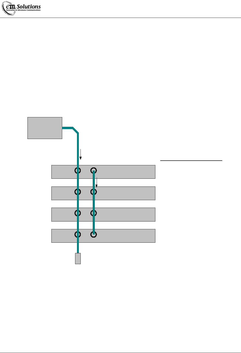
EtherMux® TDMA
Version D Document Number: 0234U02 Installation & Commissioning Manual
Issue Date: 17/02/09 Page 47 of 59
Basestation Synchronization and GPS Overview
Basestation Synchronization
Basestation Synchronization eliminates interference between co-located basestations. It works by ensuring that all basestations
transmit simultaneously, and all receive simultaneously. This prevents a basestation from transmitting while other co-located
basestations are listening.
GPS Synchronization
GPS Synchronization is a feature that helps control interference between neighbouring networks. It requires a GPS receiver at
each basestation site. The 1pps output from the GPS receiver is used to ensure that all basestations, from all basestation sites,
transmit and receive simultaneously.
Typical Installation Diagram
GPS
Receiver
AB
AB
AB
AB
Optional
termination
to match GPS
output impedance
=Master
Lock to GPS = Yes
=NO
BS Synch
Mute if not synched
=Slave
Lock to GPS = Yes
=NO
BS Synch
Mute if not synched
=Slave
Lock to GPS = Yes
=NO
BS Synch
Mute if not synched
=Slave
Lock to GPS = Yes
=NO
BS Synch
Mute if not synched
Preferred Configuration
Typical installation combining basestation and GPS synchronization.
Operation in Typical Configuration
This section describes how synchronization behaves for the typical installation as shown above.
Master basestation
The uppermost terminal is configured as the Master. This means it will generate framing pulses on its SYNCH-B connector.
These pulses are used by the Slaves to synchronize themselves to the Master. Once the Slaves are synchronized to the Master,
all of the basestations will transmit and receive simultaneously, eliminating interference between them.

EtherMux® TDMA
Version D Document Number: 0234U02 Installation & Commissioning Manual
Issue Date: 17/02/09 Page 48 of 59
The Master is also configured to Lock-to-GPS. It will synchronize itself to a GPS signal on its SYNCH-A connector. Once the
Master is locked to GPS, it will transmit and receive simultaneously with all other basestations that are locked to GPS.
Slave basestations
The Slave terminals will listen for framing pulses on their SYNC-B connectors. If framing pulses are detected, the Slave will
synchronize itself to the Master. Once synchronized, the Slave will transmit and receive simultaneously with the Master. If that
Master is locked to GPS, then the Slave will effectively be GPS locked, this will operate synchronously with all other GPS
locked Masters and their Slaves.
The slaves are also configured to Lock-to-GPS. This means that if the Master fails, and stops providing framing pulses on
SYNC-B, the slaves will synchronize themselves to the GPS signal.
Failure Handling
GPS Failure
(No signal from GPS unit)
The Master basestation will continue to operate, because “Mute if not synched” is set
to No.
The Slaves will remain synchronized to the Master. This means that basestations at
the site with GPS failure can continue to operate without interfering with each other.
The basestation site with GPS failure may interfere with operations at other
basestation sites.
Master Fails
(and stops generating framing pulses)
The Slaves will immediately switch to using the GPS signal for synchronization.
There will be no interruption to the radio connection.
GPS and Master
Failure
The Slaves will no longer be synchronized to an external source,
and will switch to using their internal references.
They will, however, continue to operate, because “Mute if not
synched” is set to No. When the internal references drift apart,
the Slaves will start interfering with each other, causing
degraded performance.
Operation in Other Configurations
Setting “Mute if not synched” to Yes
This setting mutes a basestation if it is not properly synchronized. This is useful for preventing an
unsynchronized basestation from interfering with other basestations.
• A Master will be muted if it is unable to lock to a GPS Signal, but is configured to do so.
• A Slave will be muted if it is unable to synchronize to either a GPS Signal, or to framing pulses from a Master.
• When a Master is muted, it also stops generating framing pulse for its Slaves. This causes the Slaves to mute,
unless they are GPS synchronized.
Synchronization without GPS
Co-located basestations can be synchronized without GPS by connecting all the SYNC-B ports together, and leaving the
SYNC-A ports disconnected. Each terminal should have “Lock to GPS” set to No.
The basestations will not interfere with each other, but might interfere with other nearby basestation sites.
Installation Notes
• SYNCH-A is always the GPS signal input
• SYNCH-B is always used for the basestation synchronization signal. It is an output for a MASTER and an input
for SLAVES.
• The GPS synchronization (SYNCH-A) cable impedance should be chosen based on the GPS unit's output type. If
the GPS unit has a 50 or 75 ohm output impedance, then the cable impedance should match it. A termination load
should also be used. If a GPS unit has a standard digital output the cable impedance can be 50 or 75 ohms.

EtherMux® TDMA
Version D Document Number: 0234U02 Installation & Commissioning Manual
Issue Date: 17/02/09 Page 49 of 59
• The basestation synchronization (SYNCH-B) cable impedance can be 50 or 75 ohms.
• All basestations must be configured with the same fixed TDD split ratio, and must operate in shared-time mode.
Configuration
There are three configuration settings related to synchronization. They are found in the Configuration-
MAC page. “Installer” privileges are required to configure these variables.
• BS Synchronization Master/Slave/Off
• Lock To GPS Yes/No
• Mute if Not Synched Yes/No
BS Synchronization
Master The terminal generates framing pulses on the SYNC-B
connector.
Slave The terminal listens for framing pulses on the SYNC-B connector.
If framing pulses are detected, the terminal synchronizes to the framing pulses.
If framing pulses are not detected, the terminal will synchronize to a GPS signal if
“Lock to GPS” is enabled.
Off The terminal will not listen for, or generate, any framing signals on SYNC-B
Lock to GPS
Yes Synchronize to GPS signal on SYNC-A.
If the terminal is configured as a Slave, it will preferentially synchronize to framing
pulses on SYNCH-B. If the framing pulses aren't detected, the terminal will
synchronize to the GPS signal on SYNCH-A
No The terminal does not attempt to synchronize its transmit and receive timing to the
GPS signal.
Note however, if a GPS signal is detected on SYNCH-A, the terminal will lock its
reference oscillator to the GPS signal.
Mute if Not Synched
Yes Mute the terminal (i.e. stop transmitting) if it is not properly synchronized to either
GPS or the framing pulses from a Master basestation.
This is to prevent an unsynchronized basestation from causing interference.
If a Master basestation loses GPS synchronization, and it has been configured to lock
to GPS, it will stop providing framing pulses for Slave basestations. If its Slaves are
also set to mute if not synched, they will stop transmitting unless they are
synchronized to GPS. This to prevent Slaves from synchronizing to a Master that is
itself not properly synchronized
No The terminal will not stop transmitting if it loses synchronization.
This setting will allow a basestation site to continue to operate if it has lost GPS
synchronization. The network performance may degrade due to interference.

EtherMux® TDMA
Version D Document Number: 0234U02 Installation & Commissioning Manual
Issue Date: 17/02/09 Page 50 of 59
Status and Alarms
Synchronization status information can be found in the Status-MAC web page. The following variables may be available,
depending upon configuration.
Terminal Synched Yes – if the terminal is properly synchronized
No – if the terminal is not properly synchronized.
This variable is hidden if the terminal is not configured to synchronize. That is, it is hidden
when
● Lock to GPS is set to NO; and
● BS Synchronization is set to MASTER or OFF.
The meaning of “properly synchronized” depends on the configuration.
Master:
Yes if synchronized to GPS, otherwise No.
Slave with Lock to GPS enabled:
Yes if synchronized to either GPS or framing
pulses from a Master, otherwise No.
Slave with Lock to GPS disabled:
Yes if synchronized to framing pulses from a
Master, otherwise No.
GPS Locked Yes – if the terminal is GPS synchronized
No – if the terminal is GPS synchronized
This variable is hidden if “Lock to GPS” is set to NO.
Alarms
Alarms can be configured for the two status variables. The configuration can be accessed under the MAC tab of the
Configuration-Alarms web page. Note that these alarms are only available if the synchronization configuration variables are
properly set.
Co-location with basesations from other manufacturers
The up and downlink timing of the EtherMux®-TDMA can be adjusted to align with the operation of TDD basestations from
other manufacturers. This is useful when co-locating the EtherMux®-TDMA with other manufacturers' basestations.
Contact EM Solutions for further information.
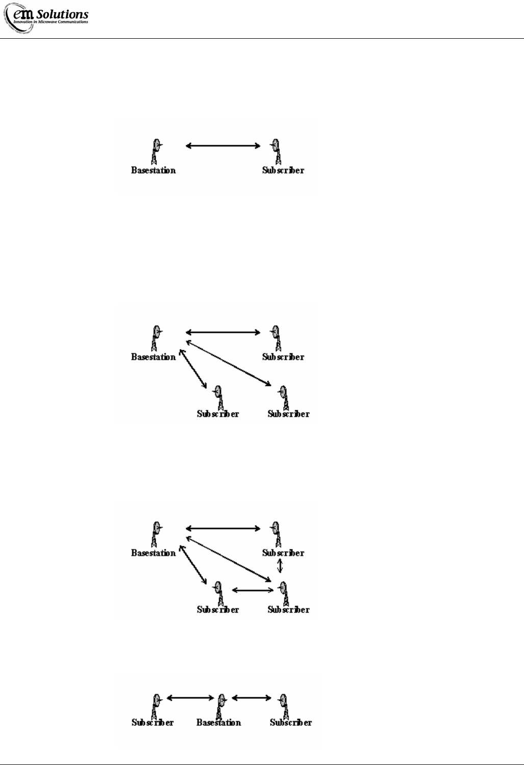
EtherMux® TDMA
Version D Document Number: 0234U02 Installation & Commissioning Manual
Issue Date: 17/02/09 Page 51 of 59
Deployment Scenarios
This section describes a number of common deployment scenarios.
Point-to-Point mode
This simplest scenario is where a pair of EtherMux®-TDMA devices are deployed to create a single high-speed data link.
One device is configured as a basestation and once device is configured as a subscriber.
Two different configurations involve the downlink (BS -> SS) vs the uplink (SS -> BS) capacity.
In a backhaul scenario these would typically be equal (50/50), whereas in an ISP-link scenario, the downlink would typically
be higher than the uplink (perhaps 70/30)
ISP mode
This scenario involves a single basestation attached to the internet, with one or more subscribers in PTMP mode.
The subscribers only communicate via the basestation, not other subscribers, and the downlink capacity is higher than the
uplink capacity.
Private Network mode
This scenario is similar to the ISP mode, however subscribers are able to communicate directly with each other via the
basestation.
Repeater mode
The repeater scenario involves extending the PTP link over two separate links, often to accommodate geographic features such
as a hill.

EtherMux® TDMA
Version D Document Number: 0234U02 Installation & Commissioning Manual
Issue Date: 17/02/09 Page 52 of 59
In-Band Anti-Interference
Overview
In some installations, there may be frequency re-use meaning that transmissions on one network may interfere with another
network on the same frequency and channel width. Several mechanisms are used to prevent in-band interference.
The interference has four major forms: Basetation to Basestation, Basestation to Subscriber, Subscriber to Basestation and
Subscriber to Subscriber. Two of the interference forms (Basestation to Basestation and Subscriber to Subscriber) are
automatically taken care of. The other two forms are optionally handled as they both have advantages and disadvantages to
each. Unless the disadvantages are too great for the specific network, enabling the two optional anti-interference measures is
highly recommended.
When any of these interference situations are encountered, a MAC error flag is set and readable from the MAC status page of
the web interface. This may assist in being able to diagnose what interference is present on the system.
Basestation to Basestation interference occurs when a basestation is listening for a transmission from a subscriber and instead
hears a neighbouring basestation instead.
In such a case, the basestation that is listening is easily able to identify that the burst is from another basestation and will
automatically discard the burst.
A method to further reduce the chance of this interference is to also use GPS and Basestation Synchronisation to make sure the
basestations all transmit and receive at the same time.
Basestation to Subscriber interference occurs when a subscriber picks up the transmission from the wrong basestation.
This may occur in several situations, especially if the subscriber is trying to synchronise to the network or has lost the signal
and starts sweeping the gain to look for the basestation.
With this interference, if the subscriber doesn't check the mac ID it may follow the wrong basestations instructions/data and
cause corruption on its network and/or the other network.
To combat this, the subscriber may be configured with a BS Mac ID (see configuration). So it will ignore all other basestation
transmissions it receives.
The only disadvantage with this is that if the basestation is changed, all subscribers with this setting must be changed to have
the new basestation mac ID before they can join the network. See the configuration section for more details on this.
Subscriber to Basestation interference occurs when a basestation picks up a transmission from an incorrect subscriber (ie from
another network)
If the basestation doesn't verify that the correct subscriber has transmitted data the data the subscriber sends may interfere with
any existing data causing problems in the network.
To deal with this, an option called SS Burst Validation is used to verify that the correct Subscriber is being received from. This
reduces capacity of the system by a small amount, but may become significant when there are large numbers of subscribers or
the network is low capacity (see the configuration section for more details).
Subscriber to Subscriber interference occurs when a subscriber receives a burst from another subscriber rather than a
basestation.
This interference occurs particularly when a subscriber is trying to join a network or interference has caused the subscriber to
sweep its gain to re-acquire the basestation's signal.
The subscriber is automatically able to detect if a transmission is from a basestation, so if a subscriber transmission is received
it will discard the burst.
Configuration
SS Burst Validation (Enable/Disable)
• This is a basestation only option that when enabled tells all connected subscribers to prepend a header to each
transmission containing the last 4 bytes of their mac ID.
• When enabled, the basestation then checks each burst and if there is no header or the mac -ID does not match, the
transmission is discarded.
• When disabled the basestation will only discard the transmission if it contains the header with the mac ID in it.
• Generally enabling this option is recommended, however the loss of capacity due to the overhead of the headers
may be significant for networks with low capacity and/or a large number of active subscribers.
BS Mac ID (48-bit MAC ID to enable, set to all 0s if disabled)
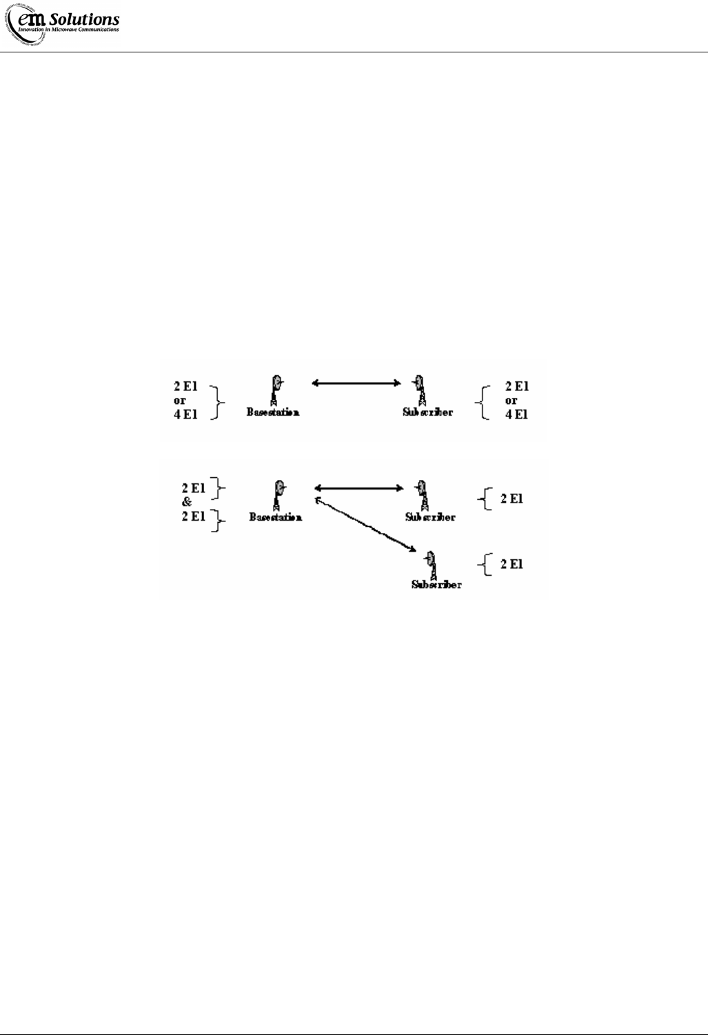
EtherMux® TDMA
Version D Document Number: 0234U02 Installation & Commissioning Manual
Issue Date: 17/02/09 Page 53 of 59
• This is a subscriber only option that when non-zero, the subscriber verifies the MAC ID of the basestation in the
transmission from the basestation.
• The subscriber will ignore the entire burst if the mac ID is non-zero and the received mac ID does not match.
Optional E1
Introduction
With the release of the EtherMux-TDMA 1.1 firmware, an option is available for 4 Unframed E1.
This option requires that an Unframed E1 card be fitted in both the Base Station and either one or two Subscribers.
Supported Configurations
The 4 Unframed E1 option allows for up to 4 E1 trunks. These trunks are configured in pairs. Thus the following
configurations are supported.
• 2 or 4 trunks to one Subscriber
• 4 trunks to 2 Subscribers
Requirements
An Unframed E1 card must be fitted in the Base Station and one or two Subscribers.
Each pair of E1s requires approximately 5Mbits/s of data capacity in each direction.
For example, if one pair is configured (2 E1s), 5Mbits/s is required on the uplink and the downlink.
Configuration
All E1 configuration is done via the web interface on the Base Station.
Navigate to Configuration->E1 Link->TDM
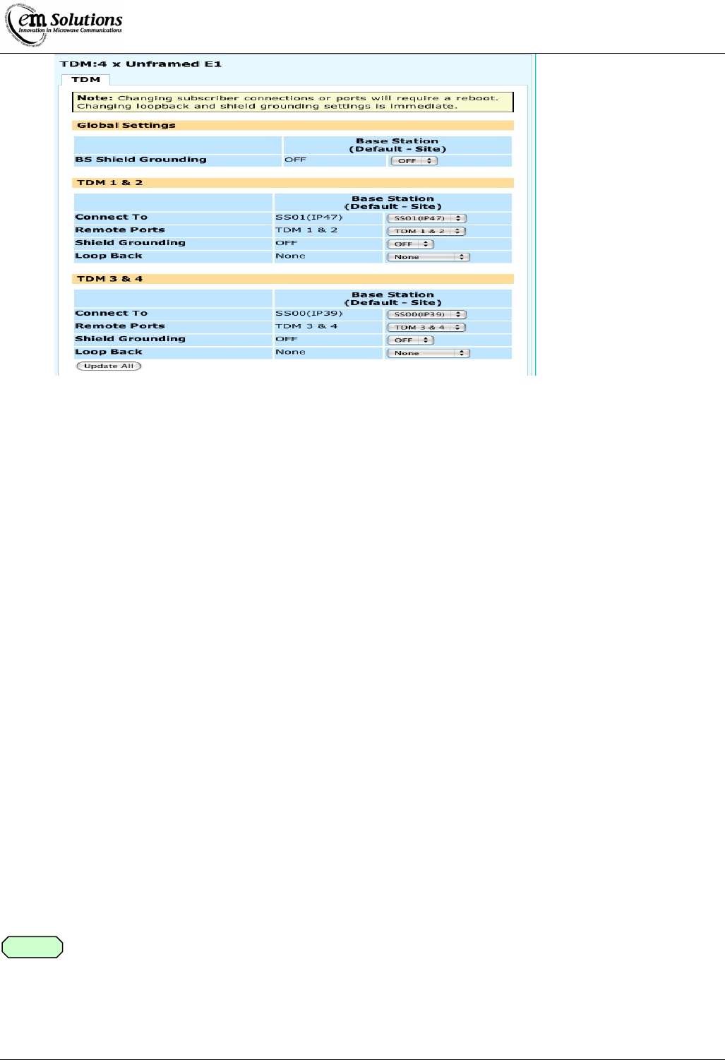
EtherMux® TDMA
Version D Document Number: 0234U02 Installation & Commissioning Manual
Issue Date: 17/02/09 Page 54 of 59
There are three sections: Global Settings, TDM 1 & 2 and TDM 3 & 4
Global Settings
The BS Shield Grounding setting determines whether the shield grounding relay is enabled on the Base Station.
TDM 1 & 2
This section determines the settings for the E1 ports TDM 1 and TDM 2.
First, Connect To should be set to indicate the Subscriber to which these ports should be connected.
Select one of the configured Subscribers or None to disable these ports.
Next, Remote Ports should be set to indicate the corresponding ports on the Subscriber. For example, to connect TDM 1 & 2 to
the same ports on the Subscriber, choose TDM 1 & 2.
The Shield Grounding setting determines whether the shield grounding relay is enabled on the Subscriber.
The Loop Back setting can be used for testing during installation. In normal operation, set this to None.
Otherwise, it may be set to one of two modes:
• Base Station
In this mode, E1 data is looped at the Base Station -- locally for the Base Station E1 ports and remotely for the
Subscriber E1 ports.
• Subscriber
In this mode, E1 data is looped at the Subscriber -- remotely for the Base Station E1 ports and locally for the
Subscriber E1 ports.
TDM 3 & 4
This section works identically to the TDM 1 & 2 section, except for E1 ports TDM 3 and TDM 4.
If all 4 E1 ports are connected to the same Subscriber, the Shield Grounding setting should be the
same in both sections, otherwise the results will be unpredictable.
The Shield Grounding and Loop Back settings take effect immediately, while any changes to the connected Subscribers or
Remote Ports take effect after a reboot.
Note

EtherMux® TDMA
Version D Document Number: 0234U02 Installation & Commissioning Manual
Issue Date: 17/02/09 Page 55 of 59
Testing
In a bench testing scenario, it is simple enough to connect a BERT across the Base Station and Subscriber, or to add a loopback
on one port, however testing after installation can be more tricky.
In this scenario, the Loop Back setting can be used for testing without requiring physical access to the other end of the link.
Local Loopback at Base Station
In this mode, the E1 data will be looped back at the Base Station.
• First, set the Loop Back setting to Base Station
• Next connect a BERT (both Rx and Tx) to the port under test
• The BERT should report no errors.
Remote Loopback at Base Station
In this mode, the E1 data will be sent over the link to the Subscriber where it will be looped back to the Base Station.
• Set the Loop Back setting to Subscriber.
• Next connect a BERT (both Rx and Tx) to the port under test
• The BERT should report no errors.
Similar tests can be performed at the Subscriber.
Trouble Shooting
Should you encounter difficulties installing or using the EtherMux®-TDMA product, please consult the table below for
suggested solutions. If this does not solve your problem contact EM Solutions' Customer Support:
No LEDs illuminate front panel Check power supply is connected and on.
Four LEDs in left column continuously
flash rapidly Flash memory has been corrupted, or device is faulty. Contact EM
Solutions.
Can't access terminal's webpage, or
can't ping a local terminal. Check Ethernet link integrity
Check IP address
Check IP settings on host. Do they match the subnet of the device.
Try rebooting device.
Subscriber doesn't connect to
Basestation Check antenna alignment.
Check RF cabling
Check that the centre frequency and channel width are the same on the
Basestation and the Subscriber.
Check that the MAC mode (PTP/PTMP) is the same on the Basestation
and the Subscriber.
Subscriber connects, but rx power is
much lower than expected. Check antenna alignment.
Check RF cabling
Check TX power in webpage
Subscriber connects, but at a lower
modulation (giving a lower capacity) Check RX power. If too low, see above.
Check for interference on same channel, or adjacent channel.

EtherMux® TDMA
Version D Document Number: 0234U02 Installation & Commissioning Manual
Issue Date: 17/02/09 Page 56 of 59
Appendix A:
FCC Compliance – 01-274H (3650-3675MHz ODU) only
FCC INTERFERENCE STATEMENT
Federal Communication Commission Interference Statement
This equipment has been tested and found to comply with the limits for a Class A digital device, pursuant to part 15 of
the FCC rules. These limits are designed to provide reasonable protection against harmful interference when the
equipment is operated in a commercial environment. This equipment generates, uses and can radiate radio frequency
energy and, if not installed and used in accordance with the instruction manual, may cause harmful interference to radio
communications. Operation of this equipment in a residential area is likely to cause harmful interference in which case
the user will be required to correct the interference at his own expense.
This device complies with Part 15 of the FCC Rules. Operation is subject to the following two conditions: (1) This
device may not cause harmful interference, and (2) this device must accept any interference received, including
interference that may cause undesired operation.
The equipment has been approved for use only with approved external antennas described in this section; use of any
other antenna may void the user’s authority to operate the equipment.
Any changes or modifications not expressly approved by the party responsible for compliance could
void the user's authority to operate this equipment.
RF Radiation Exposure Statement
To satisfy the FCC RF exposure requirements for RF transmitting devices, a distance of at least 23cm
(11in) should be maintained between the antenna of this device and any person during device
operation.
This equipment should be installed and operated as described in this manual to satisfy the RF
exposure compliance.
Caution
Warning
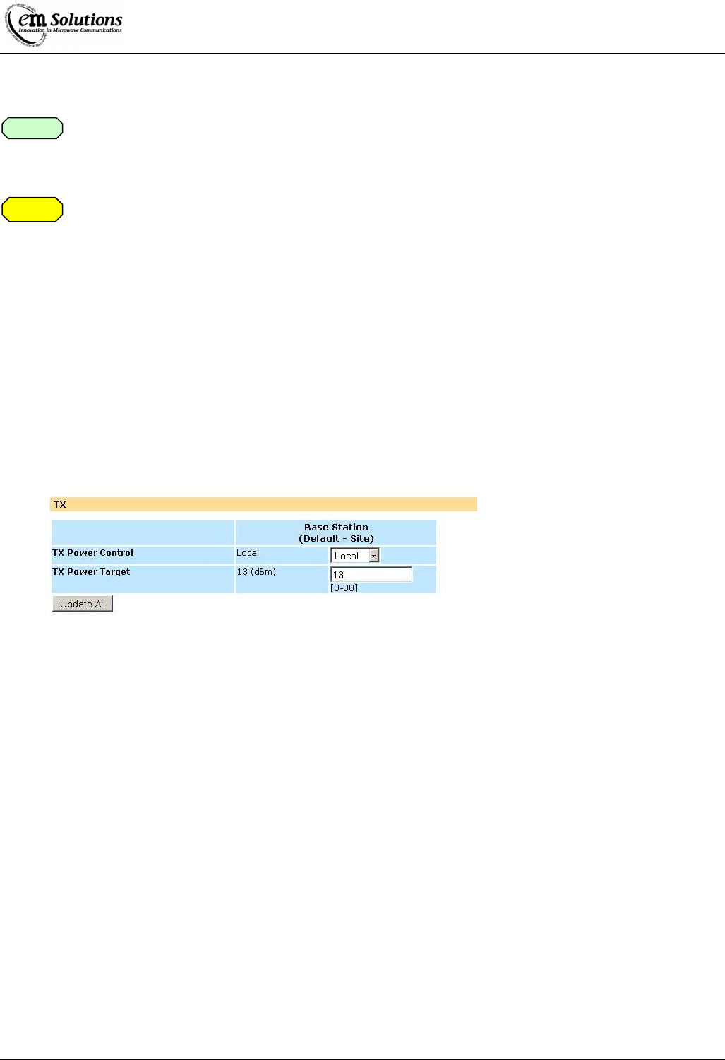
EtherMux® TDMA
Version D Document Number: 0234U02 Installation & Commissioning Manual
Issue Date: 17/02/09 Page 57 of 59
FCC Transmitter Power Settings for EMS nominated Antennas:
The RF output power and selection must be professionally programmed and installed by the
manufacturer or trained professional installer. These settings may have to be altered to take into
account any cable losses.
Transmitted Power Levels and peak EIRP power density should not exceed the requirements of FCC
Section 90.1321(a) (90.205). As per 90.1321(a) – The maximum EIRP is limited to 25 Watts/25 MHz
(44 dBm/25 MHz), and the peak EIRP power density is limited to 1W/MHz (30dBm/MHz).
Calculation for EIRP (Equivalent Isotropically Radiated Power) – RMS value
EIRP (RMS) = P + A – C
Where P is output power setting (RMS value)
A is EUT antenna gain
C is EUT cable loss
Determining the Maximum TX power setting for Local Power Control
The maximum TX power (rms) value that can be set at the web interface is limited by the peak EIRP power density
specification for a given antenna gain and cable loss. The following formula can be used to determine the webpage
setting for Local power control, as shown below. This equation is based on measured results of the peak EIRP power
density, with margin included to ensure compliance with the specification.
Maximum TX Power Target = integer value of [ 27dBm – Antenna gain (dB) + Cable loss (dB) ]
This is shown for a number of recommended antennas in the following table.
Note
Caution

EtherMux® TDMA
Version D Document Number: 0234U02 Installation & Commissioning Manual
Issue Date: 17/02/09 Page 58 of 59
Antenna Models
Manufacturer Type Model Antenna
Gain (dBi)
Net
antenna
gain **
(dB)
Maximum TX
Power - webpage
setting (dBm)
Lanbowan Solid
Parabolic ANT3500D24P 24.5 23.0 4
Grid
Parabolic ANT3500D19A 19 17.5 9
Grid
Parabolic ANT3500D22G 22 20.5 6
Grid
Parabolic ANT3500D27A 27 25.5 1
Shenglu /
Vinncom Panel TDJ-SA3500-20-16 20 18.5 8
Panel
TDJ-SA3500-15-
90V 15 13.5 13
Panel
TDJ-SA3500-17-
60V 17 15.5 11
Grid
Parabolic TDJ-PST3500-25-06 25 23.5 3
Radiowaves Parabolic
SP2-3.5
or
SPD2-3.5NS
24.2 22.7 4
Parabolic
SP3-3.5
or
SPD3-3.5NS
27.7 26.2 0
Panel SEC-35V-40-18 18 16.5 10
Panel SEC-35V-60-17 17.5 16 11
Panel
SEC-35V-90-16
or
SEC-35V-90-16HP
16 14.5 12
** Net antenna gain is calculated as the antenna gain less cable loss of 1.5dB
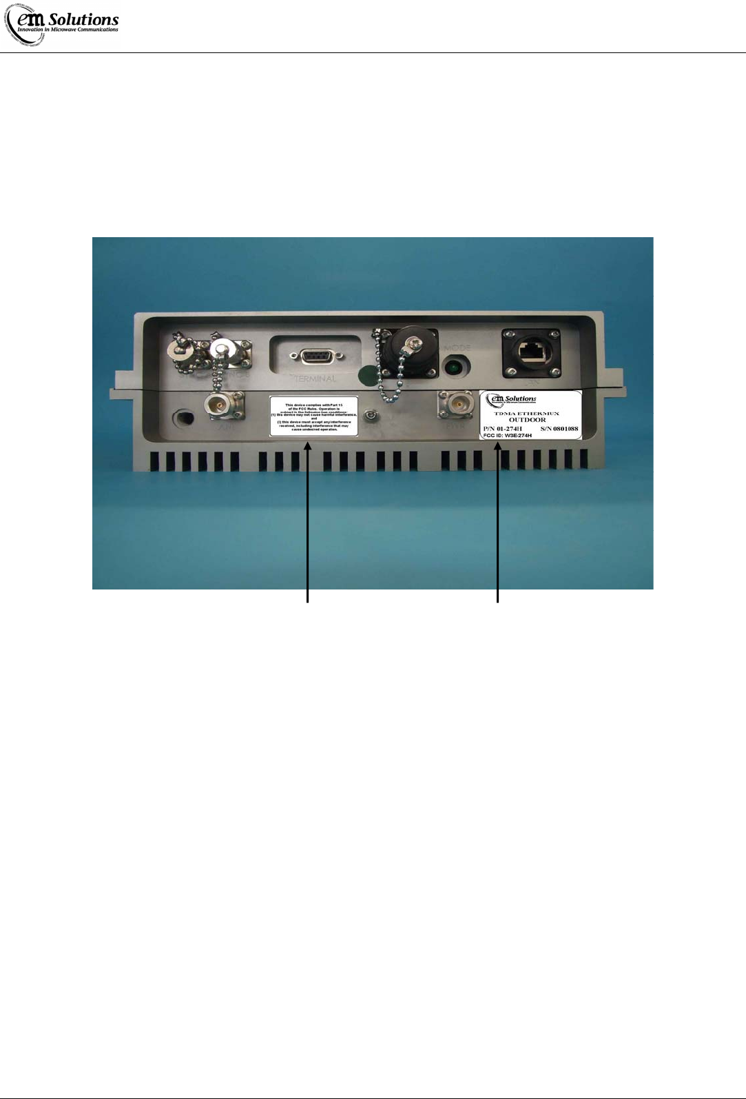
EtherMux® TDMA
Version D Document Number: 0234U02 Installation & Commissioning Manual
Issue Date: 17/02/09 Page 59 of 59
FCC Identification Labels
EtherMux® TDMA Outdoor Terminal
Main Label
with
FCC ID
Compliance
Statement