Edelbrock 72230 Users Manual Adjustable Control Module For Harley Davidson Nitrous System
2015-02-06
: Edelbrock Edelbrock-72230-Users-Manual-538014 edelbrock-72230-users-manual-538014 edelbrock pdf
Open the PDF directly: View PDF ![]() .
.
Page Count: 4
Page 1of 4
2004 Edelbrock Corporation
Brochure #63-0131 Catalog #72230
Rev. 5/04
Please study these instructions carefully before installing your new Edelbrock Nitrous System. Failure to
follow instructions will void warranty and may cause damage to parts and/or personal injury. If you have any questions
or problems, please call our Technical Hotline at: 1-800-416-8628, 7:00 am - 5:00 pm, Pacific Standard Time, Monday
through Friday or e-mail us at edelbrock@edelbrock.com.
NOTE: Before starting this project, be sure that the motorcycle is cool enough to work on and that the battery is
disconnected (negative cable first). Failure to disconnect the battery could result in electrical damage to the adjustable
control module and/or personal injury. PRE-INSTALLATION
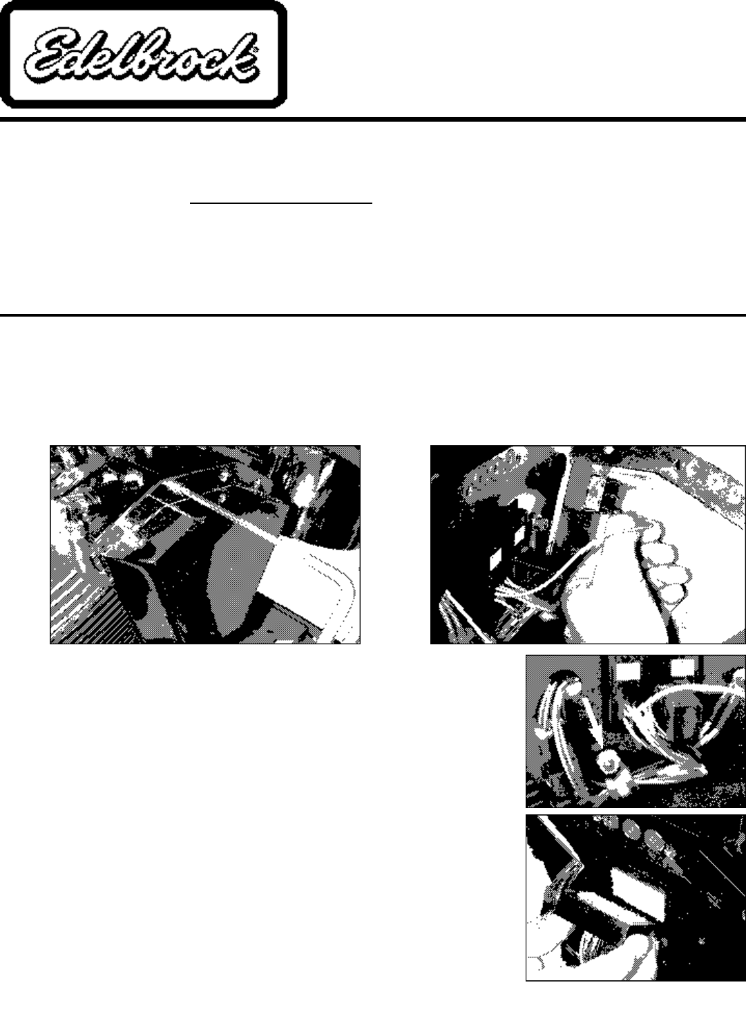
1. Make sure that the Nitrous Module Housing is easily accessible. Remove any components from the motorcycle
that could be blocking access to the unit.
2. Remove the Chrome Cover Plate from the Nitrous Module Housing unit by removing the four allen head bolts from
the top of the cover plate (Fig. 1). Be sure to disconnect the wires routing to your arming switch, mounted on the
Chrome Cover Plate, to prevent damage when the cover is removed completely (Fig. 2). This will allow you access
to the Control Module for the proper removal and installation of your new component.
ADJUSTABLE CONTROL MODULE
for Edelbrock Harley-Davidson Nitrous Systems
Kit #72230
INSTALLATION INSTRUCTIONS
3Remove the wire clamp located on the inside of the backing plate (Fig. 3).
4. Disconnect all of the Nitrous Control Module wires from their destinations.
This entails disconnecting all of the following connections:
• Battery (red wire)
• Module ground (black wire)
• Tachometer lead (green wire)
• Single Fire or Dual Fire Mode Wire (gray wire)
• Arming switch (orange wire)
• Fuel pump power (blue wire)
• Fuel pump ground (black wire)
• Solenoid connectors (black plastic clips)
5. After all connections have been removed, remove the Nitrous Control Module
from the backing plate. This can be done by using a flat head screwdriver
to pry the module off the plate (Fig. 4). The module is held on by double
sided tape. Scrape off any remaining tape from the backing plate to ensure
that your new Adjustable Control Module mounts securely.
Fig 1 Fig 2
Fig 3
Fig 4
Page 2of 4
2004 Edelbrock Corporation
Brochure #63-0131 Catalog #72230
Rev. 5/04
INSTALLATION
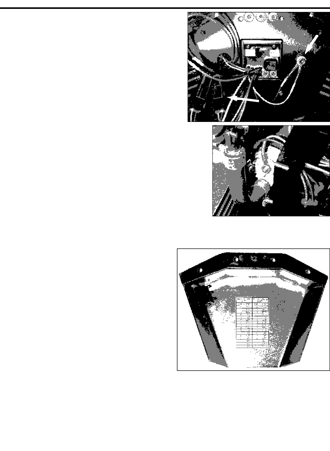
1. Install your new Adjustable Control Module onto the
backing plate in the same location as the Control Module
that you just removed. Install the module so that the
adjustment controls are located on the bottom of the
module (Fig. 5).
2. Connect the black ground wire off of the adjustable
module, labeled “GND” to the backing plate using the bolt
that you previously removed (Fig. 5).
3. If using a Single Fire Ignition, leave the gray wire labeled
“SF/DF” loose and tape or cut and apply a butt connector
to the end of the wire so that it cannot contact anything. If
using a Dual Fire Ignition, connect the gray wire labeled
“SF/DF” to the same bolt as the black ground wire off the
adjustable module (Fig. 5).
4. Route the blue and black fuel pump wires, labeled “PUMP”, through
the wire port on the backing plate. Connect the blue fuel pump wire
to the positive (+) terminal of the nitrous system fuel pump and the
black fuel pump wire to the negative (-) terminal of the nitrous
system fuel pump (Fig. 6).
5. Connect the two black male solenoid clip terminals to their
corresponding female clip terminals routed through the wire port of
the backing plate (Fig. 5). Be sure that you connect the “FUEL”
terminal to the fuel solenoid wire terminal and the “NOS” terminal to
the nitrous solenoid wire terminal.
6. Route the red and green wires through the wire port of the backing plate. Connect the green wire, labeled “TACH”,
to the tach lead. Leave the red wire disconnected at this time.
7. Using the wire clamp that you previously removed
during the Nitrous Control Module removal, route all of
the excess wire that is now in the housing through the
loop and mount this clamp in its original location, such
as depicted in Fig. 3.
7. Connect the orange wire, labeled “ARM”, to the top
terminal of the Arming Switch. Connect the remaining
wires that you previously disconnected from the
arming switch to their appropriate terminals on the
switch.
8. Install the Chrome Cover Plate using the four bolts and
washers that you removed previously.
9. Connect the red wire, labeled “13.8V”, to the battery or
key activated circuit breaker.
10. Your Adjustable Control Module has been supplied with an adjustment settings sticker for your convenience. This
sticker can be mounted wherever you feel is convenient, but we recommend placing the sticker on the inside of
the Chrome Cover Plate as depicted in Fig. 7. This will keep the sticker from being misplaced, as well as be
located in a convenient location for reference when you are adjusting your settings.
Fig 5
Fig 6
Fig 7
Page 3of 4
2004 Edelbrock Corporation
Brochure #63-0131 Catalog #72230
Rev. 5/04
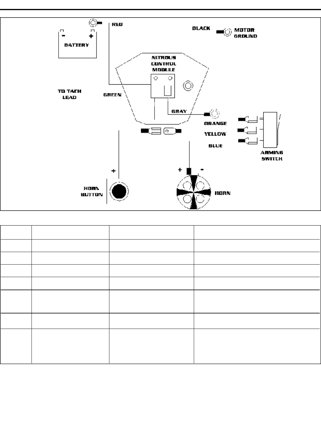
WIRING DIAGRAM
Wire System Origin Destination
Color
Red Battery Voltage Nitrous Module Harness Battery or Key activated circuit breaker
Black Module Ground Nitrous Module Harness Ground to cylinder head bolt
Green Tach Trigger wire Nitrous Module Harness Factory Tachometer lead or Coil
Orange System Arming Wire Nitrous Module Harness Top Terminal of Arming Switch
Yellow Horn interface wire Horn power lead. From Center Terminal of Arming Switch
Harness 12+ factory
Harness lead.
Blue Horn interface wire Horn power lead. From Bottom Terminal of Arming Switch
Horn 12+ Side of Horn
Gray Single or dual fire Nitrous Module Harness SF* Leave wire end loose and tape or
SF/DF Ignition lead cut and apply a butt connector.
DF* Ground wire to Module plate
Page 4of 4
2004 Edelbrock Corporation
Brochure #63-0131 Catalog #72230
Rev. 5/04
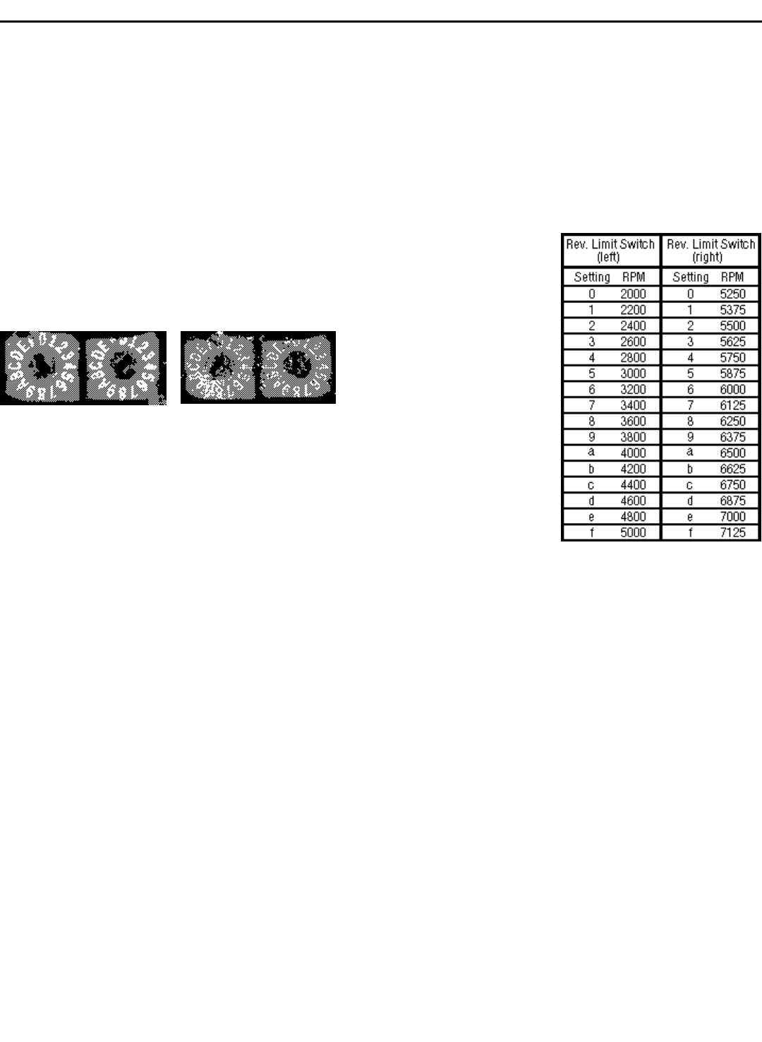
ADJUSTING THE CONTROL MODULE
The settings diagram located below is the same as the sticker that you previously installed. This diagram contains crucial
information that will allow you to select the setting that you would like your nitrous system to activate at as well as shut
down at. Depending on your engines configuration and power, the nitrous system can be programmed to activate at
between 2000 RPM and 5000 RPM and shut down between 5250 RPM and 7125 RPM. You should consult with the engine
builder and/or manufacturer to find out the rev limit for your specific engine. NEVER exceed the RPM limit of your
engine. Severe engine damage may occur!
Adjusting your control module is done very easily using a small flathead screwdriver. First, select the RPM that you would
like the nitrous system to activate at using the chart below (or the sticker supplied with the kit). Set the arrow on the left
pot to the correct number or letter for the setting you would like. Last, select the RPM
that you would like the nitrous system to de-activate and set the right pot to the correct
number or letter for the setting you would like. Below are two examples of different
settings. Once these setting have been made, your system is ready to run!
Examples:
Edelbrock General Warranty
It is the constant endeavor of Edelbrock Corporation to give our customers the highest quality products obtainable. Edelbrock
warrants each new product, except Performer Series Carburetors, Race Division Parts, Tubular Exhaust Systems, RPM Series
Mufflers, Cat-Back Systems and Performer IAS Shock Absorbers which are warranted separately, to be free from defects in both
workmanship and material for a period of one (1) year from the date of purchase, provided that the product is properly installed,
subjected to normal use and service and that the product is not modified or changed in any way, negligence by customer or
installer or used for racing or competition purposes.
Our warranty service and repair facility is located at 2700 California Street, Torrance, California 90503. Customers who believe
they have a defective product should either return it to the dealer from which it was purchased or ship it directly to Edelbrock
along with proof of purchase and a complete description of the problem. The product must be returned freight pre-paid. If a
thorough inspection of the product by the factory indicates defects in workmanship or material, our sole obligation shall be to
repair or replace the product. Warranty covers only the product itself and not the cost of installation or removal.
Edelbrock Corporation shall not be liable for any and all consequential damages occasioned by the breach of
any written or implied warranty pertaining to this sale in excess of the purchase price of the product sold.
If you have any questions regarding a product or installation,
please contact our Technical Department, toll free at 1-800-416-8628
from 7:00 am to 5:00 pm PST,
Monday through Friday.
Shown above:
The left pot is at setting 7
7=3400RPM activation
The right pot is at setting A
A=6500RPM de-activation
Shown above:
The left pot is at setting 2
2=2400RPM activation
The right pot is at setting 8
8=6250RPM de-activation
