Emerson Digital Controller Valves 788 Dvc Maintenance Instructions
788dvc 1f1bb1fc-6229-4c94-82ae-c2e74f66d9e2 Emerson Marine Instruments 788 DVC User Guide |
2015-01-05
: Emerson Emerson-Digital-Controller-Valves-788-Dvc-Maintenance-Instructions-165644 emerson-digital-controller-valves-788-dvc-maintenance-instructions-165644 emerson pdf
Open the PDF directly: View PDF ![]() .
.
Page Count: 48
- Page 1
- Page 2
- Page 3
- Page 4
- Page 5
- Page 6
- Page 7
- Page 8
- Page 9
- Page 10
- Page 11
- Page 12
- Page 13
- Page 14
- Page 15
- Page 16
- Page 17
- Page 18
- Page 19
- Page 20
- Page 21
- Page 22
- Page 23
- Page 24
- Page 25
- Page 26
- Page 27
- Page 28
- Page 29
- Page 30
- Page 31
- Page 32
- Page 33
- Page 34
- Page 35
- Page 36
- Page 37
- Page 38
- Page 39
- Page 40
- Page 41
- Page 42
- Page 43
- Page 44
- Page 45
- Page 46
- Page 47
- Page 48
Operating and Maintenance Instructions
Part Number- 3-9008-556 Revision D
December 2012
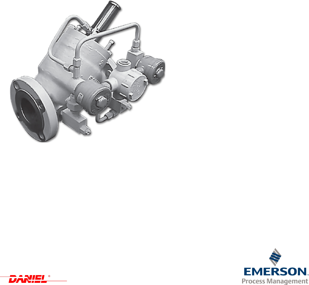
Daniel Model 788 DVC digital control
TM
valves
2", 3", 4", 6" and 8" sizes
This page intentionally left blank.

Important safety instructions
Daniel Measurement and Control, Inc. (Daniel) designs, manufactures and tests products to function
within specific conditions. Because these products are sophisticated technical instruments, it is
important that the owner and operation personnel strictly adhere both to the information printed on
the product nameplate and to all instructions provided in this manual prior to installation, operation,
and maintenance.
Daniel also urges you to integrate this manual into your training and safety program.
BE SURE ALL PERSONNEL READ AND FOLLOW THE INSTRUCTIONS IN THIS MANUAL
AND ALL NOTICES AND PRODUCT WARNINGS.
Installing, operating or maintaining a Daniel Product improperly could lead to serious injury or
death from explosion or exposure to dangerous substances. To reduce this risk:
• Comply with all information on the product, in this manual, and in any local and national
codes that apply to the product.
• Do not allow untrained personnel to work with this product.
Use Daniel parts and work procedures specified in this manual.
Product owners (Purchasers):
• Use the correct product for the environment and pressures present. See technical data or
product specifications for limitations. If you are unsure, discuss your needs with your Daniel
representative.
• Inform and train all personnel in the proper installation, operation, and maintenance of this
product.
• To ensure safe and proper performance, only informed and trained personnel should install,
operate, repair and maintain this product.
• Verify that this is the correct instruction manual for your Daniel product. If this is not the
correct documentation, contact Daniel at 1-713-827-6314. You may also download the
correct manual from:
http://www.daniel.com
• If you resell or transfer this product, it is your responsibility to forward this instruction
manual along with the product to the new owner or transferee.
• ALWAYS READ AND FOLLOW THE INSTALLATION, OPERATIONS,
MAINTENANCE AND TROUBLESHOOTING MANUAL(S) AND ALL PRODUCT
WARNINGS AND INSTRUCTIONS.
• Do not use this equipment for any purpose other than its intended service. This may result
in property damage and/or serious personal injury or death.

Product operation personnel:
• To prevent personal injury, personnel must follow all instructions of this manual prior to and
during operation of the product.
• Follow all warnings, cautions, and notices marked on, and supplied with, this product.
• Verify that this is the correct instruction manual for your Daniel product. If this is not the
correct documentation, contact Daniel at 1-713-827-6314. You may also download the
correct manual from:
http://www.daniel.com
• Read and understand all instructions and operating procedures for this product.
• If you do not understand an instruction, or do not feel comfortable following the instructions,
contact your Daniel representative for clarification or assistance.
• Install this product as specified in the INSTALLATION section of this manual per
applicable local and national codes.
• Follow all instructions during the installation, operation, and maintenance of this product.
• Connect the product to the proper pressure sources when and where applicable.
• Ensure that all connections to pressure and electrical sources are secure prior to, and during,
equipment operation
• Use only replacement parts specified by Daniel. Unauthorized parts and procedures can
affect this product's performance, safety, and invalidate the warranty. "Look-a-like"
substitutions may result in deadly fire, explosion, release of toxic substances or improper
operation.
• Save this instruction manual for future reference.
Safety signal words and symbols
Pay special attention to the following signal words, safety alert symbols and statements:
Indicates a hazardous situation which, if not avoided, will result in death or serious injury.
Warning indicates a hazardous situation which, if not avoided, could result in death or serious injury.
Caution indicates a hazardous situation which, if not avoided, could result in minor or moderate
injury.
Notice is used to address safety messages or practices not related to personal injury.
Safety alert symbol
This is a safety alert symbol. It is used to alert you to potential physical injury hazards. Obey all
safety messages that follow this symbol to avoid possible injury or death.
This page intentionally left blank.
Notice
THE CONTENTS OF THIS PUBLICATION ARE PRESENTED FOR INFORMATIONAL PURPOSES ONLY, AND
WHILE EVERY EFFORT HAS BEEN MADE TO ENSURE THEIR ACCURACY, THEY ARE NOT TO BE
CONSTRUED AS WARRANTIES OR GUARANTEES, EXPRESSED OR IMPLIED, REGARDING THE
PRODUCTS OR SERVICES DESCRIBED HEREIN OR THEIR USE OR APPLICABILITY. ALL SALES ARE
GOVERNED BY DANIEL’S TERMS AND CONDITIONS, WHICH ARE AVAILABLE UPON REQUEST. WE
RESERVE THE RIGHT TO MODIFY OR IMPROVE THE DESIGNS OR SPECIFICATIONS OF SUCH PRODUCTS
AT ANY TIME.
DANIEL DOES NOT ASSUME RESPONSIBILITY FOR THE SELECTION, USE OR MAINTENANCE OF ANY
PRODUCT. RESPONSIBILITY FOR PROPER SELECTION, USE AND MAINTENANCE OF ANY DANIEL
PRODUCT REMAINS SOLELY WITH THE PURCHASER AND END-USER.
TO THE BEST OF DANIEL’S KNOWLEDGE THE INFORMATION HEREIN IS COMPLETE AND ACCURATE.
DANIEL MAKES NO WARRANTIES, EXPRESSED OR IMPLIED, INCLUDING THE IMPLIED WARRANTIES
OF MERCHANTABILITY AND FITNESS FOR A PARTICULAR PURPOSE WITH RESPECT TO THIS MANUAL
AND, IN NO EVENT, SHALL DANIEL BE LIABLE FOR ANY INCIDENTAL, PUNITIVE, SPECIAL OR
CONSEQUENTIAL DAMAGES INCLUDING, BUT NOT LIMITED TO, LOSS OF PRODUCTION, LOSS OF
PROFITS, LOSS OF REVENUE OR USE AND COSTS INCURRED INCLUDING WITHOUT LIMITATION FOR
CAPITAL, FUEL AND POWER, AND CLAIMS OF THIRD PARTIES.
PRODUCT NAMES USED HEREIN ARE FOR MANUFACTURER OR SUPPLIER IDENTIFICATION ONLY AND
MAY BE TRADEMARKS/REGISTERED TRADEMARKS OF THESE COMPANIES.
DANIEL AND THE DANIEL LOGO ARE REGISTERED TRADEMARKS OF DANIEL INDUSTRIES, INC. THE
EMERSON LOGO IS A TRADEMARK AND SERVICE MARK OF EMERSON ELECTRIC CO.
COPYRIGHT © 2012
BY DANIEL MEASUREMENT AND CONTROL, INC.
HOUSTON, TEXAS, U.S.A.
All rights reserved. No part of this work may be reproduced or
copied in any form or by any means - graphic, electronic or
mechanical - without first receiving the written permission of
Daniel Measurement and Control, Inc., Houston, Texas, U.S.A.

Warranty and limitation of liability
1. LIMITED WARRANTY: Subject to the limitations contained in Section 2 herein, Daniel Measurement & Control,
Inc. (“Daniel”) warrants that the licensed firmware embodied in the Goods will execute the programming instructions
provided by Daniel, and that the Goods manufactured by Daniel will be free from defects in materials or workmanship
under normal use and care and Services will be performed by trained personnel using proper equipment and
instrumentation for the particular Service provided. The foregoing warranties will apply until the expiration of the
applicable warranty period. Goods are warranted for twelve (12) months from the date of initial installation or eighteen
(18) months from the date of shipment by Daniel, whichever period expires first. Consumables and Services are
warranted for a period of 90 days from the date of shipment or completion of the Services. Products purchased by Daniel
from a third party for resale to Buyer (“Resale Products”) shall carry only the warranty extended by the original
manufacturer. Buyer agrees that Daniel has no liability for Resale Products beyond making a reasonable commercial
effort to arrange for procurement and shipping of the Resale Products. If Buyer discovers any warranty defects and
notifies Daniel thereof in writing during the applicable warranty period, Daniel shall, at its option, correct any errors that
are found by Daniel in the firmware or Services or repair or replace F.O.B. point of manufacture that portion of the
Goods or firmware found by Daniel to be defective, or refund the purchase price of the defective portion of the
Goods/Services. All replacements or repairs necessitated by inadequate maintenance, normal wear and usage, unsuitable
power sources or environmental conditions, accident, misuse, improper installation, modification, repair, use of
unauthorized replacement parts, storage or handling, or any other cause not the fault of Daniel are not covered by this
limited warranty, and shall be at Buyer’s expense. Daniel shall not be obligated to pay any costs or charges incurred
by Buyer or any other party except as may be agreed upon in writing in advance by Daniel. All costs of dismantling,
reinstallation and freight and the time and expenses of Daniel’s personnel and representatives for site travel and diagnosis
under this warranty clause shall be borne by Buyer unless accepted in writing by Daniel. Goods repaired and parts
replaced by Daniel during the warranty period shall be in warranty for the remainder of the original warranty period or
ninety (90) days, whichever is longer. This limited warranty is the only warranty made by Daniel and can be amended
only in a writing signed by Daniel. THE WARRANTIES AND REMEDIES SET FORTH ABOVE ARE EXCLUSIVE.
THERE ARE NO REPRESENTATIONS OR WARRANTIES OF ANY KIND, EXPRESS OR IMPLIED, AS TO
MERCHANTABILITY, FITNESS FOR PARTICULAR PURPOSE OR ANY OTHER MATTER WITH RESPECT
TO ANY OF THE GOODS OR SERVICES. Buyer acknowledges and agrees that corrosion or erosion of materials is
not covered by this warranty.
2. LIMITATION OF REMEDY AND LIABILITY: DANIEL SHALL NOT BE LIABLE FOR DAMAGES CAUSED
BY DELAY IN PERFORMANCE. THE REMEDIES OF BUYER SET FORTH IN THIS AGREEMENT ARE
EXCLUSIVE. IN NO EVENT, REGARDLESS OF THE FORM OF THE CLAIM OR CAUSE OF ACTION
(WHETHER BASED IN CONTRACT, INFRINGEMENT, NEGLIGENCE, STRICT LIABILITY, OTHER TORT OR
OTHERWISE), SHALL DANIEL’S LIABILITY TO BUYER AND/OR ITS CUSTOMERS EXCEED THE PRICE TO
BUYER OF THE SPECIFIC GOODS MANUFACTURED OR SERVICES PROVIDED BY DANIEL GIVING RISE
TO THE CLAIM OR CAUSE OF ACTION. BUYER AGREES THAT IN NO EVENT SHALL DANIEL’S
LIABILITY TO BUYER AND/OR ITS CUSTOMERS EXTEND TO INCLUDE INCIDENTAL, CONSEQUENTIAL
OR PUNITIVE DAMAGES. THE TERM “CONSEQUENTIAL DAMAGES” SHALL INCLUDE, BUT NOT BE
LIMITED TO, LOSS OF ANTICIPATED PROFITS, REVENUE OR USE AND COSTS INCURRED INCLUDING
WITHOUT LIMITATION FOR CAPITAL, FUEL AND POWER, AND CLAIMS OF BUYER’S CUSTOMERS.

DANIEL MODEL 788DVC DIGITAL CONTROL VALVES DEC 2012
TM
TABLE OF CONTENTS i
TABLE OF CONTENTS
1.0 INTRODUCTION ..................................................... 1-1
1.1 Aggressive Products.............................................. 1-1
1.2 Principle of Operation ............................................ 1-2
2.0 THEORY OF OPERATION ............................................. 2-1
2.1 Operational Sequence ............................................ 2-1
3.0 SPECIFICATIONS .................................................... 3-1
4.0 INSTALLATION AND MAINTENANCE .................................. 4-1
4.1 Recommended Installation Instructions . . . . . . . . . . . . . . . . . . . . . . . . . . . . . . . 4-1
4.2 General Considerations as Applied to the DL8000 . . . . . . . . . . . . . . . . . . . . . . 4-2
5.0 CYLINDER DISASSEMBLY AND REASSEMBLY . . . . . . . . . . . . . . . . . . . . . . . . . 5-1
5.1 Cylinder Assembly Removal ....................................... 5-1
5.2 Cylinder Disassembly ............................................ 5-2
5.3 Cylinder Reassembly ............................................. 5-4
5.4 Cup-Seal Replacement on Existing “AP” Option Board . . . . . . . . . . . . . . . . . . 5-5
6.0 TROUBLESHOOTING................................................. 6-1
7.0 PARTS LIST ......................................................... 7-1

DEC 2012 DANIEL MODEL 788DVC DIGITAL CONTROL VALVES
TM
TABLE OF CONTENTSii
Figures
2-1 Closed Position ....................................................... 2-2
2-2 Open - Control Position................................................. 2-3
2-3 Open Position (no control)............................................... 2-4
3-1 Flow vs Pressure Drop.................................................. 3-3
3-2 Dimensions .......................................................... 3-6
4-1 Typical Application - Bottom Loading ..................................... 4-4
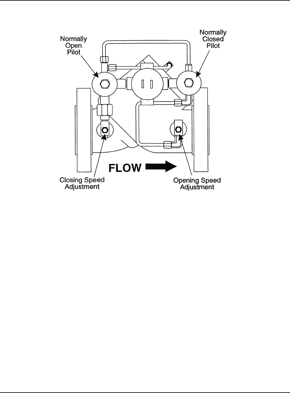
4-2 Solenoid Actuation Adjustments .......................................... 4-5
4-3 Control Valve Configuration (new for DL8000) . . . . . . . . . . . . . . . . . . . . . . . . . . . . . . 4-6
5-1 Using the Piston to Insert the Seat Ring into the 150/300 lb. Cylinder . . . . . . . . . . . . . 5-3
5-2 Cylinder Assembly Removal ............................................. 5-4
5-3 Option Assembly ...................................................... 5-6
7-1 Valve Cylinder Assembly ............................................... 7-4
Tables
3-1 Solenoid Electrical Data (150 lb. MOPD) . . . . . . . . . . . . . . . . . . . . . . . . . . . . . . . . . . . 3-5
3-2 Maximum Working Pressure............................................. 3-5
3-3 Dimensions .......................................................... 3-7
5-1 Typical Opening/Closing Speed .......................................... 5-3
6-1 Troubleshooting ...................................................... 6-2
7-1 Parts List ............................................................ 7-2
DANIEL MODEL 788DVC DIGITAL CONTROL VALVES DEC 2012
TM
INTRODUCTION 1-1
1.0 INTRODUCTION
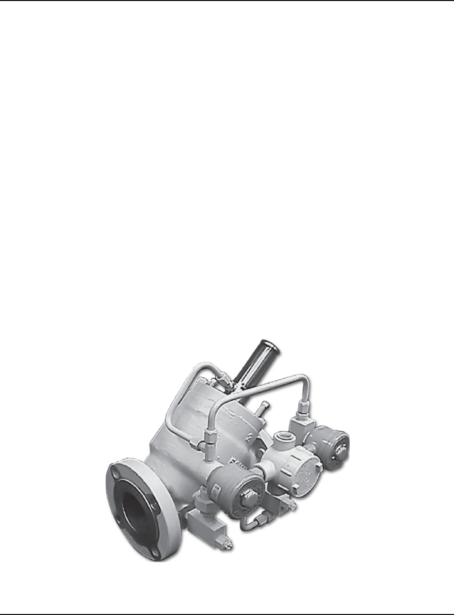
The Daniel Model 788DVC Digital Control Valve is a solenoid operated device designed to
TM
provide precise flow rate control and batch delivery of liquid products. It is used in conjunction with
an electronic batch control device such as the Daniel DL8000. The Model 788DVC valve is
automatically controlled by the DanLoad for low flow start-up, high flow rate control, low flow
shut-down, and final shut-off. It also provides for maximum flow meter accuracy by maintaining
a constant flow rate in applications with varying line pressure. The Model 788DVC features an
external pilot control loop that consists of a normally open solenoid pilot, a normally closed solenoid
pilot, strainer and opening/closing speed controls.
1.1 Aggressive Products
Some Daniel control valves have been equipped with an “AP” (Aggressive Products) cylinder
assembly. This cylinder assembly may be supplied as a direct replacement for existing units or may
be supplied with the original order. It is designed for all Daniel 2", 3", 4" and 6", 150/300 lb. ANSI,
Series 700 Valves. Spring-loaded Teflon cup-seals are utilized on the main body piston and low
®
swell Nitrile O-rings in static positions. For specific instructions for receipt, installation and
maintenance of Control Valves containing the “AP” Cylinder Assembly reference manual 3-9008-
554. Also contained within this manual are complete instructions for retrofitting existing standard
valves with the “AP” Option package.
If you have questions or need information not contained in this manual, please contact your Daniel
sales representative or the Daniel Measurement and Control service center nearest you.
DEC 2012 DANIEL MODEL 788DVC DIGITAL CONTROL VALVES
TM
INTRODUCTION1-2
1.2 Principle of Operation
Operation of the Model 788DVC Digital Control Valve is based on a balanced piston principle.
When pressure on both sides of the main valve piston are equal, a spring (located on the top of the
piston) acts as a differential force and closed the main valve piston. As pressure against the bottom
of the piston increases and exceeds the pressure exerted against the top of the piston, plus the force
of the spring, spring tension is overcome and the valve opens. Solenoid pilots are digitally controlled
- full open or full closed - and are used to determine the main valve piston position required for flow
control. Reference Figures 2-1, 2-2 and 2-3 for valve opening/closing positions.
EQUIPMENT DAMAGE
Read the entire recommended procedure for all installation operations and maintenance
procedures before attempting to install or disassemble the valve. Disassembly of this
cylinder assembly is different from previous Daniel Control Valves and requires strict
adherence to the procedures outlined in this manual.
Failure to read and comply with these procedures could result in damage to the equipment and
compromise in the integrity of the operation.

DANIEL MODEL 788DVC DIGITAL CONTROL VALVES DEC 2012
TM
THEORY OF OPERATION 2-1
2.0 THEORY OF OPERATION
The Model 700B Series Control Valve operates on a balanced-piston principle. When pressures on
both sides of the piston are equalized, a spring located on top of the piston acts as a differential force
and closes the piston. When the pressure against the bottom of the piston exceeds the pressure plus
the force of the spring exerted against the top of the piston, spring tension is overcome, and the valve
opens. See Figure 3-1 for more information.
These valves are normally closed (N.C.) and they will open when both solenoids are energized. The
valves are fail-safe as they close upon loss of power. They use the line product as the source of
hydraulic power to open and close the main valve piston. An electrical supply controlled by an
electronic preset is the source of power for energizing the two solenoids.
These valves are used mainly for batching and they provide a means of reducing the rate of flow on
on startup and before final shut-off of a predetermined delivery. This minimizes surges of pressure
and line shock and assures ± 1/4 gallon shut-off (sizes 2 inch - 8 inch) of the preset volume.
The total system generally consists of three pieces of equipment: (1) a flowmeter, (2) electronic
preset with digital control, and (3) a digital electric control valve. The electronic preset is the device
used to set the predetermined volume of liquid that is to be delivered by the valve.
2.1 Operational Sequence
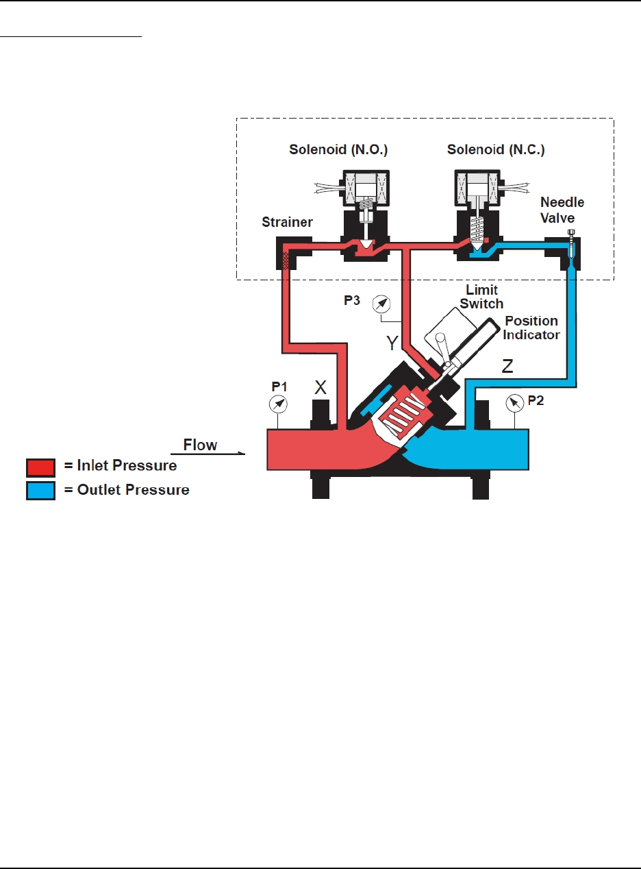
With both solenoids de-energized, the main valve is closed as shown in Figure 2-1. The main valve
can be infinitely positioned anywhere between 0 - 100% open by digital control of the solenoids.
With both solenoids energized, as shown in Figure 2-3, the valve begins to open. It will only open
to the programmed flow rate set in the electronic preset. Normally, the electronic preset is
programmed to digitally control low flow start-up, maximum flow rate, low flow rate before shut-off
and no flow. The electronic preset will automatically energize and de-energize the solenoids to
position the main valve to limit the required flow rate. When the required flow rate is reached, the
solenoids will be as shown in Figure 2-2. This hydraulically locks the main valve piston in position.
Should flow increase, the valve will close slightly to adjust to the required flow rate. All of the
positioning is done by digitally controlling the two solenoids as shown in Figure 2-1, 2-2 and 2-3.
DEC 2012 DANIEL MODEL 788DVC DIGITAL CONTROL VALVES
TM
THEORY OF OPERATION2-2
CLOSED POSITION -
The normally closed solenoid is closed. The normally open solenoid is open. Y-port (P3) to Z-port
(P2) is closed. X-port (P1) and Y-port (P3) pressures are balanced. The main valve spring being the
differential force, closes the piston and keeps it seated.
Figure 2-1. Closed Position
DANIEL MODEL 788DVC DIGITAL CONTROL VALVES DEC 2012
TM
THEORY OF OPERATION 2-3
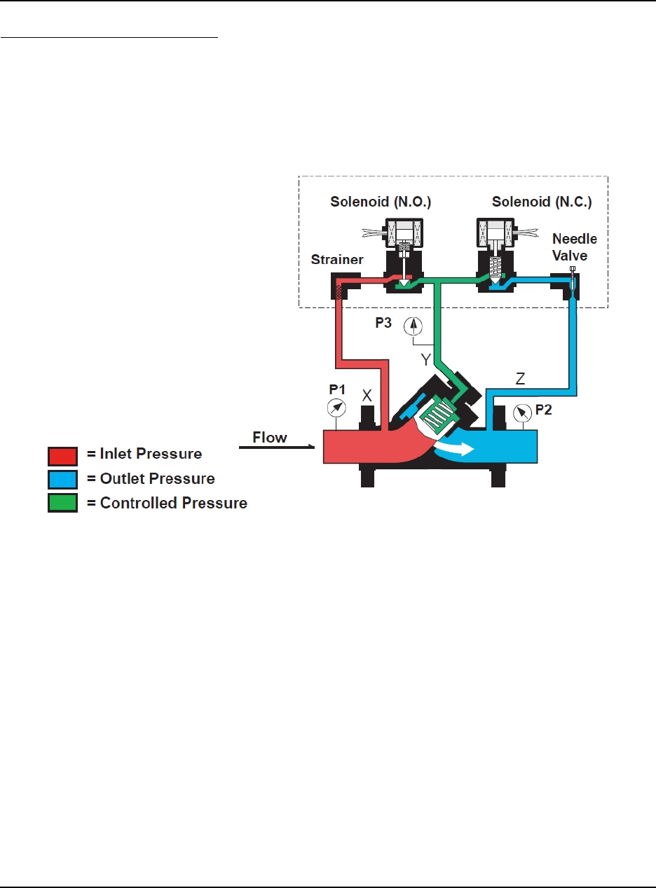
OPEN - CONTROL POSITION -
The normally closed solenoid is closed. The normally open solenoid is closed. Y-Port (P3) to Z-port
(P2) is closed. X-port (P1) to Y-port (P3) is closed. The product cannot flow to or from the top of
the piston. The piston is hydraulically locked in position until the electronic preset commands the
valve to open or close as required to maintain the desired high flow rate, or low flow rate.
Figure 2-2. Open - Control Position
DEC 2012 DANIEL MODEL 788DVC DIGITAL CONTROL VALVES
TM
THEORY OF OPERATION2-4
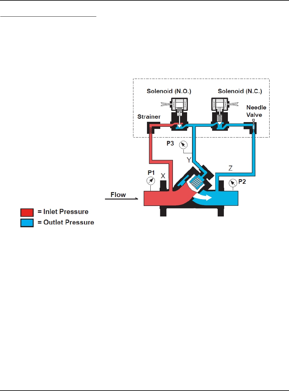
OPEN POSITION - (no control) -
The normally closed solenoid is open. The normally open solenoid is closed. Y-port (P3) is open to
Z-port (P2). X-port (P1) is closed off by the normally open solenoid. The pressure on the bottom of
the piston (P1) is greater than the pressure at (P3) plus the spring force; (P1 minus P2) is equal to
or greater than the spring force. Therefore, (P1) pressure pushes the piston open. No flow control
is required.
Figure 2-3. Open Position (no control)

DANIEL MODEL 788DVC DIGITAL CONTROL VALVES DEC 2012
TM
SPECIFICATIONS 3-1
3.0 SPECIFICATIONS
PERSONAL INJURY AND/OR EQUIPMENT DAMAGE
Do not exceed specifications listed below.
Failure to heed this warning could result in serious injury and/or damage to the equipment.
Pressure Class
150 lb., 300 lb., or 600 lb. ANSI steel
DIN PN 16, 40, 64, and 100
Safe Working Temperature Ranges
Standard: -20/F, -29/C to 150/F, 66/C
Optional: -20/F, -29/C to 250/F, 121/C
Maximum Safe Working Pressure
150 lb. ANSI steel body - 285 psi (1965 kPa)
3001b. ANSI steel body -740 psi (5100 kPa)
600 lb. ANSI steel body - 1480 psi (10,200 kPa)
DIN PN 16-16 bars
DIN PN 25 - 25 bars
DIN PN 40 - 10 bars
DIN PN 64 - 64 bars
DIN PN 100 - 100 bars
Size:
2-in., 3-in., 4-in., 6-in., 8-in.
Ratings
UL and CSA Listed:
- Class I, Group C and D, Div.1; Class II, Group E, F and G
- Explosion-Proof NEMA types 7C, 7D, 9E, 9F and 9G
- NEMA 4 Weather-Proof
- ATEX II2G Eexe/Eexd

DEC 2012 DANIEL MODEL 788DVC DIGITAL CONTROL VALVES
TM
SPECIFICATIONS3-2
INMETRO Certification:
- Certificate Number: NCC 12.1244 X
- INMETRO Marking: Ex d nC IIB T3 Gc
Ex d IIC T* Gb
*See Tables 1 and 2 in the certificate for temperature range details.
Special condition for safe use: When the digital control valve is assembled with solenoid models
80174, 80173, 80143, 80144, HP80143, 8014G2 and F8003G1, the temperature of the process fluid
must not be greater than 40°C.
Connections
2" through 6" ANSI flanged
Valve Capacity
Valve Size 2" 3" 4" 6" 8"
Cv* - gpm 86 186 309 688 1296
*Cv based on valve full open using water at 60/F (16/C)
For Valve Flow vs. Pressure Loss see Figure 3-1. Consult manual 3-9008-550, Capacity
Charts for valve sizing.
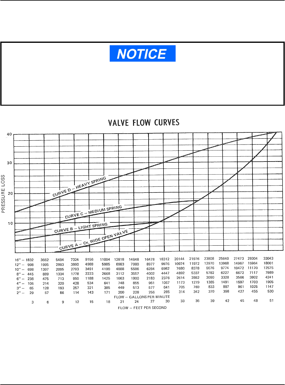
Flow vs. Pressure Drop (See Figure 3-1)
Curve A - Wide open valves with no spring resistance.
Applicable to pilot operated valves with Y and Z ports vented to sump, atmosphere or pump station.
Curve B - Light main valve spring.
Applies only to On-Off valves, rate of flow control valves and check valves with ANSI 150 to 300
lb. flanges.
Curve C - Medium main valve spring.
Applies to all modulating control valves except rate of flow and valves using ANSI 600 lb. flanges.
Curve D- Heavy main valve spring.
Applies to all valves using ANSI 600 lb. flanges.
DANIEL MODEL 788DVC DIGITAL CONTROL VALVES DEC 2012
TM
SPECIFICATIONS 3-3
The main valve is full open when curves B, C, and D intersect Curve A. After they intersect,
continue reading pressure drop curve from curve A. In applications requiring a constant pressure
drop over 40 psid a heavy main valve spring must be used.
Curves A, B, C and D are based on water (specific gravity: 1.0). For liquids having a specific
gravity of 0.8 or greater, multiply the pressure drop shown times the actual specific gravity.
This results in the actual pressure drop. For specific gravities less than 0.8, use 0.8 to get the
corrected pressure drop (curves B, C and D only).
Figure 3-1. Flow vs Pressure Loss

DEC 2012 DANIEL MODEL 788DVC DIGITAL CONTROL VALVES
TM
SPECIFICATIONS3-4
Materials of Construction
Main Valve Body
steel, ASTM-352 LCC
Cylinder Head
steel, ASTM-352 LCC
Main Valve Cylinder
steel
nickel coated steel
Main Valve Piston
Standard: stainless steel
Seat Ring
steel
nickel coated steel
Seals
steel
O-rings
Standard: Viton dynamic, Buna-N
®
Optional: EPR, Kalrez , Low-Swell Nitrile, Neoprene™, Viton -A, Viton -GFLT
®®®
Optional
Visual position indicator
Microswitch-type indicator
AP (aggressive products) option
Pressure/Temperature Ratings
The maximum working pressure for the Model 700B Series Control Valve is based on
temperature/pressure rating of the ANSI B16.5 flanges. The Table 3-2 lists the maximum working
pressure of ASTM 352 LCC WCb at 100°F.
DANIEL MODEL 788DVC DIGITAL CONTROL VALVES DEC 2012
TM
SPECIFICATIONS 3-5
Other Internal Parts
stainless steel
Pilot Valve Body and Trim
stainless steel
Tubing
steel or stainless steel
Table 3-1. Solenoid Electrical Data (150 lb. MOPD)
Voltage* Current (Inrush) Current Holding
110/50 Vac 0.71 amps 0.37 amps
120/60 Vac 0.65 amps 0.34 amps
220/50 Vac 0.36 amps 0.19 amps
240/60 Vac 0.33 amps 0.17 amps
*DC voltage and 440/480 Vac upon request
DEC 2012 DANIEL MODEL 788DVC DIGITAL CONTROL VALVES
TM
SPECIFICATIONS3-6
Table 3-2. Maximum Working Pressure
Pressure/Temperature ASTM A352 LCC WCB
150# ANSI/-20 to 100/F 285 psig WP
150# ANSI/150/F 272 psig WP
150# ANSI/250/F 245 psig WP
150# ANSI/450/F 185 psig WP
300# ANSI/-20 to 100/F 740 psig WP
300# ANSI/150/F 707 psig WP
300# ANSI/250/F 665 psig WP
300# ANSI/450/F 334 psig WP
600# ANSI/-20 to 100/F 1480 psig WP
600# ANSI/150/F 1415 psig WP
600# ANSI/250/F 1332 psig WP
600# ANSI/450/F 667 psig WP
P/N 16/-29 to 66/C 16 bar WP
P/N 16/121/C 15.8 bar WP
P/N 16/232/C 13.7 psig WP
P/N 25/-29 to 66/C 25 bar WP
P/N 25/121/C 24.7 bar WP
P/N 25/232/C 21.6 psig WP
P/N 40/-29 to 66/C 40 bar WP
P/N 40/121/C 39.6 bar WP
P/N 40/232/C 34.4 bar WP
P/N 63/-29 to 66/C 63 bar WP
P/N 63/121/C 62.4 bar WP
P/N 63/232/C 54.3 bar WP
P/N 100/-29 to 66/C 100 bar WP
P/N 100/121/C 99 bar WP
P/N 100/232/C 86.2 bar WP
DANIEL MODEL 788DVC DIGITAL CONTROL VALVES DEC 2012
TM
SPECIFICATIONS 3-7
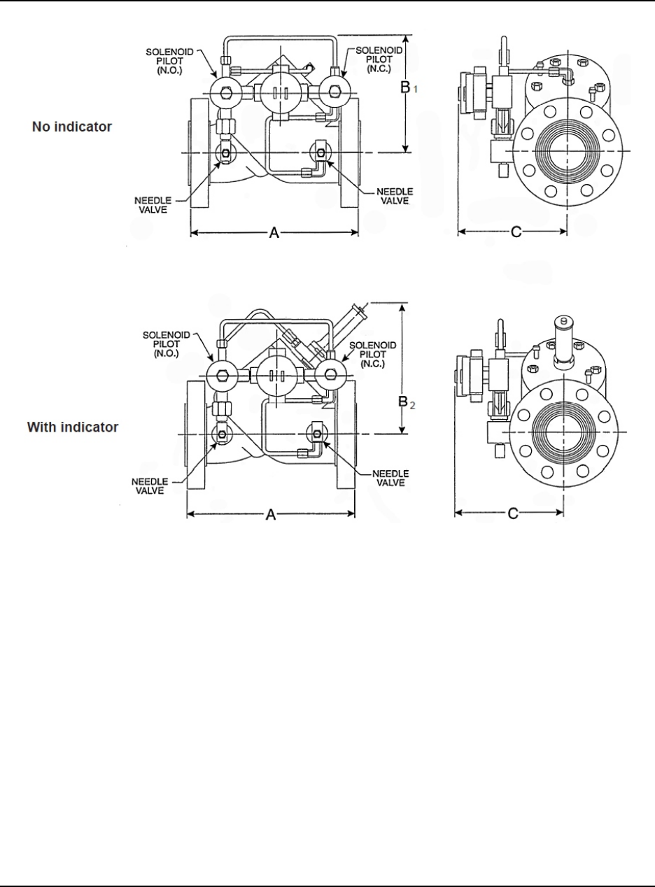
Figure 3-2. Dimensions
DEC 2012 DANIEL MODEL 788DVC DIGITAL CONTROL VALVES
TM
SPECIFICATIONS3-8
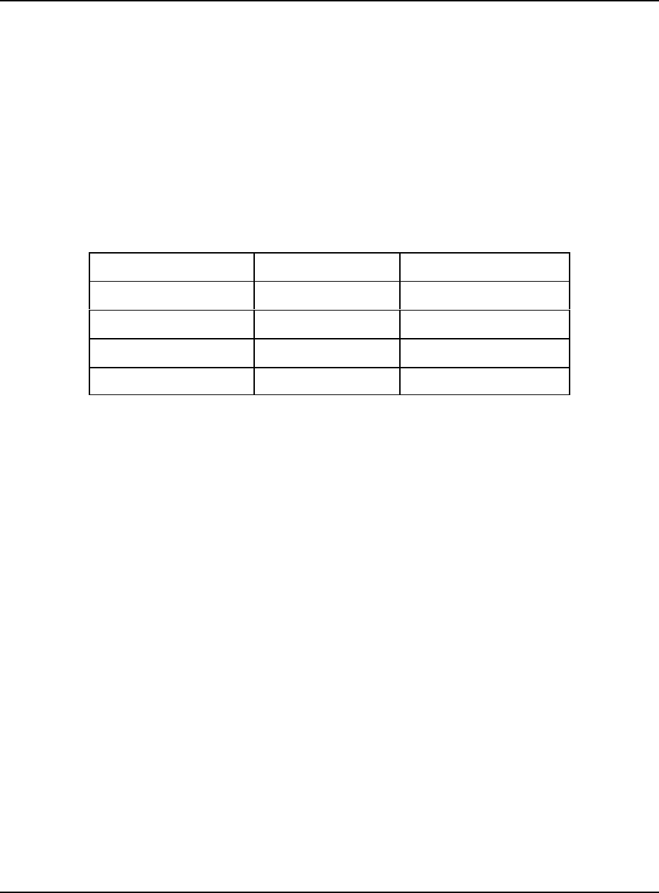
Table 3-3. Dimensions (see Figure 3-2)
Valve
Size
A
150# ANSI
A
300# ANSI
1
B
No Indicator
2
B
With Indicator
C
2" 10-1/4" 10-1/2" 9" 11" 8.25"
260 mm 267 mm 229 mm 279 mm 210 mm
3" 11" 11" 9" 12" 8-3/4"
279 mm 333 mm 229 mm 305 mm 222 mm
4" 13" 13" 9" 12-1/2" 9"
330 mm 368 mm 229 mm 318 mm 229 mm
6" 17" 17" 12" 15-3/4" 11"
432 mm 454 mm 305 mm 400 mm 279 mm
8" 22.25" 22.25" 15" 17.5" 11.75"
565 mm 591 mm 381 mm 445 mm 298 mm

DANIEL MODEL 788DVC DIGITAL CONTROL VALVES DEC 2012
TM
INSTALLATION AND MAINTENANCE 4-1
4.0 INSTALLATION AND MAINTENANCE
The most common application of the Daniel Model 788DVC Digital Control Valve is for truck
loading of petroleum products. The valve may be used with a variety of flow meter types,
including Coriolis and turbine meters, as shown in Figure 4-1. In this installation the DL8000 is
the primary batch and control device. Reference Figure 4-2 and 4-3 for configuration
information.
Flow must be horizontal or vertical up but never vertical down.
4.1 Recommended Installation Instructions
As with all control valves, it is most important that proper installation be accomplished if the
valve is to operate as designed. Preliminary set-up should include the following steps:
1. Evaluate the metering system in the process line to determine that criteria pertinent to
digital valve control is met.
• Minimum meter K-factor: 20 pulses/unit
• Minimum meter pulse frequency (low flow): 50 Hz
• Minimum opening time (shut-off to full open): 1.5 seconds
• Minimum closing time (full open to shut-off): 1.5 seconds
2. Reference engineering drawings for proper in-line sequence of all components.
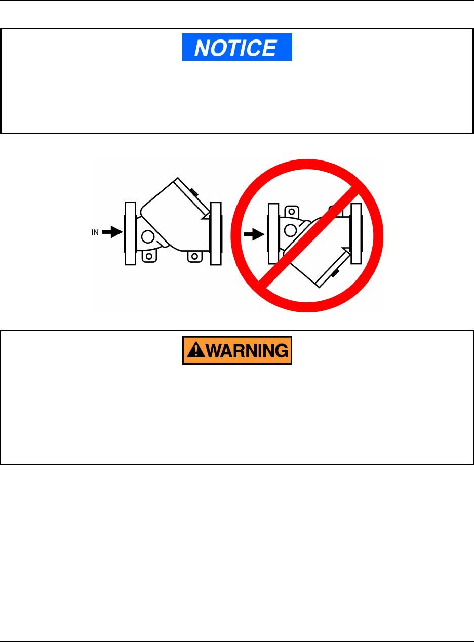
3. Check valve position. The inlet flange has been marked and is to be in the upstream
position.
4. Verify all electrical connections against wiring diagrams and unit specifications.
Reference Figure 4-3 for Control Valve configuration.
DEC 2012 DANIEL MODEL 788DVC DIGITAL CONTROL VALVES
TM
INSTALLATION AND MAINTENANCE4-2
EQUIPMENT DAMAGE
It is recommended that the external pump control be turned to the OFF position when
performing any electrical wiring installation and until initial control valve adjustments
are made in the DL8000.
Failure to comply with these procedures could result in damage to the equipment and
compromise in the integrity of the operation.
5. Flush the line of any and all contaminates.
6. Bleed as much air as possible from the system before start up.
4.2 General Considerations as Applied to the DL8000
Upon completion of the preliminary installation of the Digital Control Valve a Start-up
Adjustment Procedure must be administered. Reference “DL8000 Preset Controller Instruction
Manual”, P/N D301244X012.
DANIEL MODEL 788DVC DIGITAL CONTROL VALVES DEC 2012
TM
INSTALLATION AND MAINTENANCE 4-3
The Daniel valve may be installed with a flow direction horizontal or vertical up but should
never be installed with flow direction vertical down. When installed in a horizontal line, the
valve should be installed so that the cylinder head is at the top of the valve and not the bottom.
See below.
PERSONAL INJURY OR DEATH AND/OR PROPERTY DAMAGE
Use equipment for its intended purpose.
Use of this equipment for any purpose other than its intended purpose may result in property
damage and/or serious personal injury or death.
DEC 2012 DANIEL MODEL 788DVC DIGITAL CONTROL VALVES
TM
INSTALLATION AND MAINTENANCE4-4
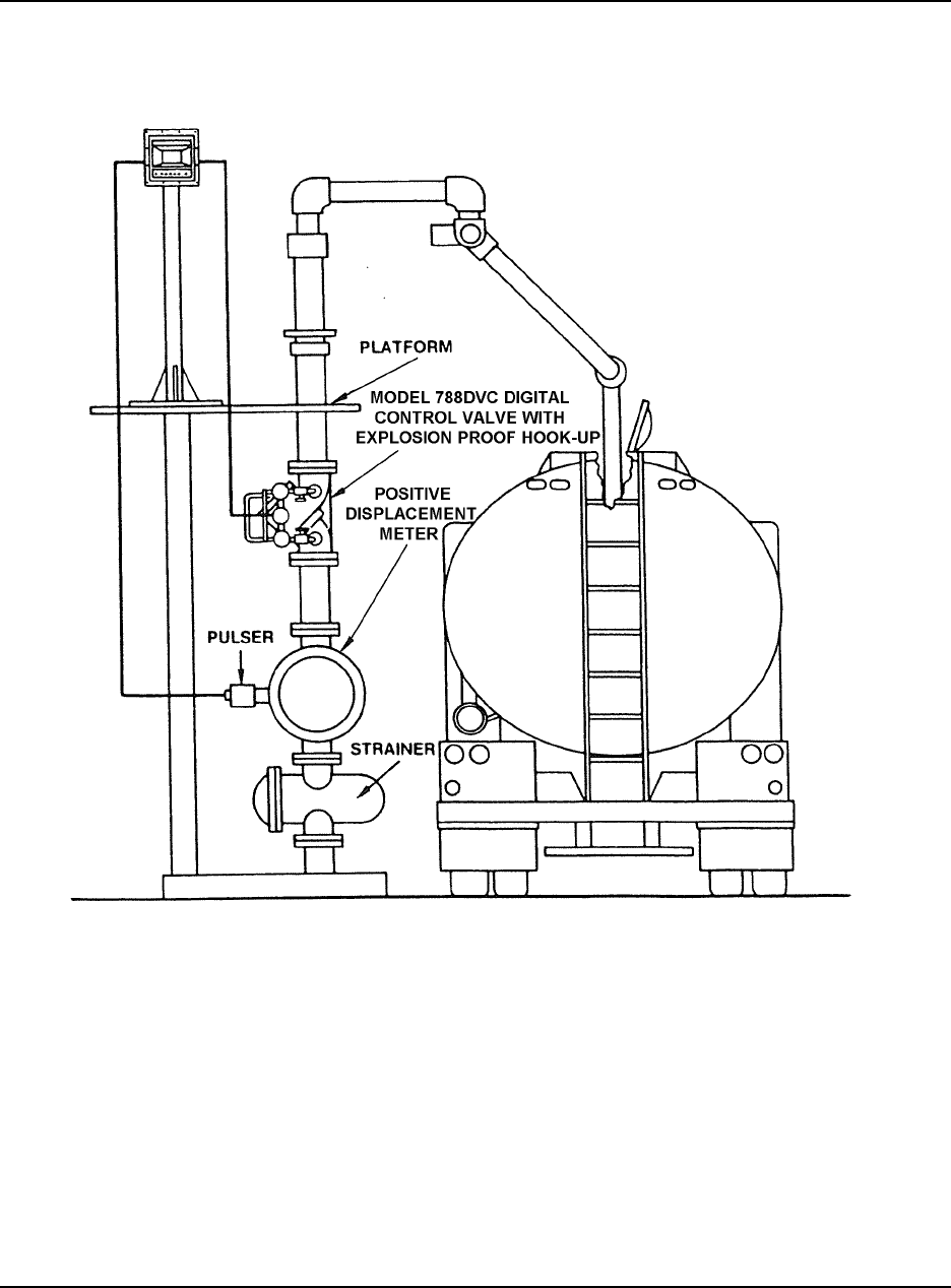
Figure 4-1. Typical Application - Top Loading
DANIEL MODEL 788DVC DIGITAL CONTROL VALVES DEC 2012
TM
INSTALLATION AND MAINTENANCE 4-5
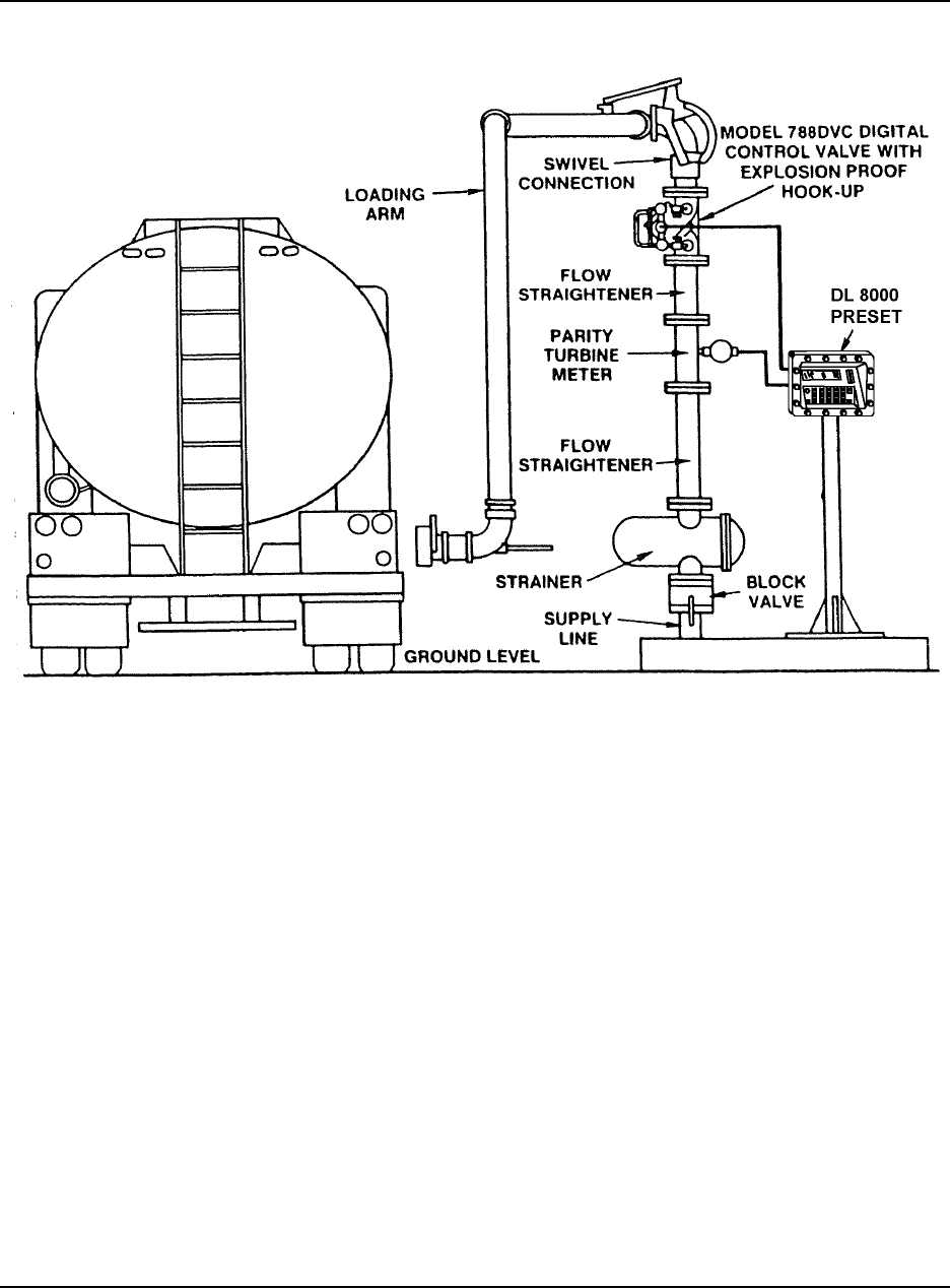
Figure 4-2. Typical Application - Bottom Loading
DEC 2012 DANIEL MODEL 788DVC DIGITAL CONTROL VALVES
TM
INSTALLATION AND MAINTENANCE4-6
Figure 4-3. Control Valve Configuration (new for DL8000)
DANIEL MODEL 788DVC DIGITAL CONTROL VALVES DEC 2012
TM
DISASSEMBLY AND REASSEMBLY 5-1
5.0 CYLINDER DISASSEMBLY AND REASSEMBLY
The following tools will be needed to disassemble and reassemble your control valve:
• socket wrench
• adjustable wrench
• T-handle or extended Allen wrench
• arbor press (may be needed for 4- and 6-inch valves)
• retaining ring pliers
Numbers in parentheses correspond with the item numbers in Table 7-1 and Figure 7-1.
EQUIPMENT DAMAGE
Read the entire recommended procedure for all installation operations and maintenance
procedures before attempting to install or disassemble the valve. Disassembly of this
cylinder assembly is different from previous Daniel Control Valves and requires strict
adherence to the procedures outlined in this manual.
Failure to read and comply with these procedures could result in damage to the equipment and
compromise in the integrity of the operation.
5.1 Cylinder Assembly Removal - All Daniel Valves
1. Isolate the Control Valve from the system and bleed off pressure.
2. Loosen and remove the tubing from the cylinder head.
3. Remove the nuts securing the cylinder assembly within the valve body.
4. Tighten the two jack screws provided in the cylinder head until the cylinder assembly has
been freed from the valve body. These screws should be tightened evenly to prevent damage
to the cylinder O-ring and binding the cylinder assembly.
5. Remove the cylinder assembly from the valve body by pulling upward and evenly using both
hands (on smaller valves) or a mechanical device (for larger models).
6. Remove the two jack screws from the cylinder head.
DEC 2012 DANIEL MODEL 788DVC DIGITAL CONTROL VALVES
TM
DISASSEMBLY AND REASSEMBLY5-2
5.2 Cylinder Disassembly
Refer to Figure 5-2.
PERSONAL INJURY AND/OR EQUIPMENT DAMAGE
Caution is required when performing any disassembly procedure as the Cylinder head is
bolted to a spring loaded cylinder assembly. Service should only be performed by trained
and qualified service personnel.
Failure to comply with recommended could result in serious injury and/or damage to the
equipment.
1. Position the cylinder assembly in an arbor press with the cylinder head (5) down. Valves
smaller than 6" may not require a press. Larger units may require the use of a spindle or
arbor press to facilitate removal of the piston assembly, in which case, the arbor should be
resting against the cylinder head.
2. Place a metal sleeve over the piston nose to protect the sense line during removal. This can
be fabricated from a pipe section and should have an internal diameter large enough to
encircle the piston nose. The length must be sufficient to accommodate complete spring
compression with allowing the sense line to strike the press plunger.
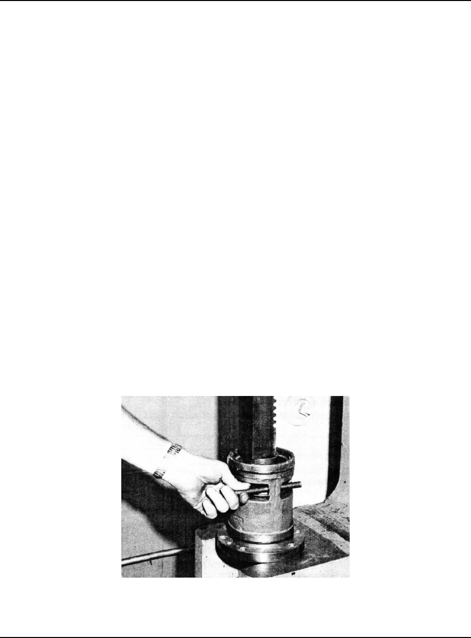
3. Using EXTREME CAUTION depress the piston against the spring until the rectangular
ports are cleared. Block the piston in the open position, fully compressed, by inserting a
suitable wedge through the port opening. Any wood, nylon or non-marring dowel or handle
that will safely guarantee piston position can be used for this operation. It is recommended
that a brass or other soft metal bar be used for this operation.
4. Remove the retaining ring, sealing ring and O-ring.
5. Using EXTREME CAUTION depress the piston against the spring and remove the piston
blocks. CAREFULLY remove the piston from the cylinder body while maintaining pressure
on the valve spring.
DANIEL MODEL 788DVC DIGITAL CONTROL VALVES DEC 2012
TM
DISASSEMBLY AND REASSEMBLY 5-3
6. Lift off the cylinder head by taking out the socket screws.
7. Remove and inspect all O-rings for nicks, cuts and wear.
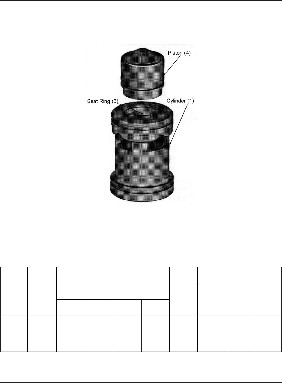
Figure 5-1. Using the Piston to Insert the Seat Ring into the 150/300 lb. Cylinder
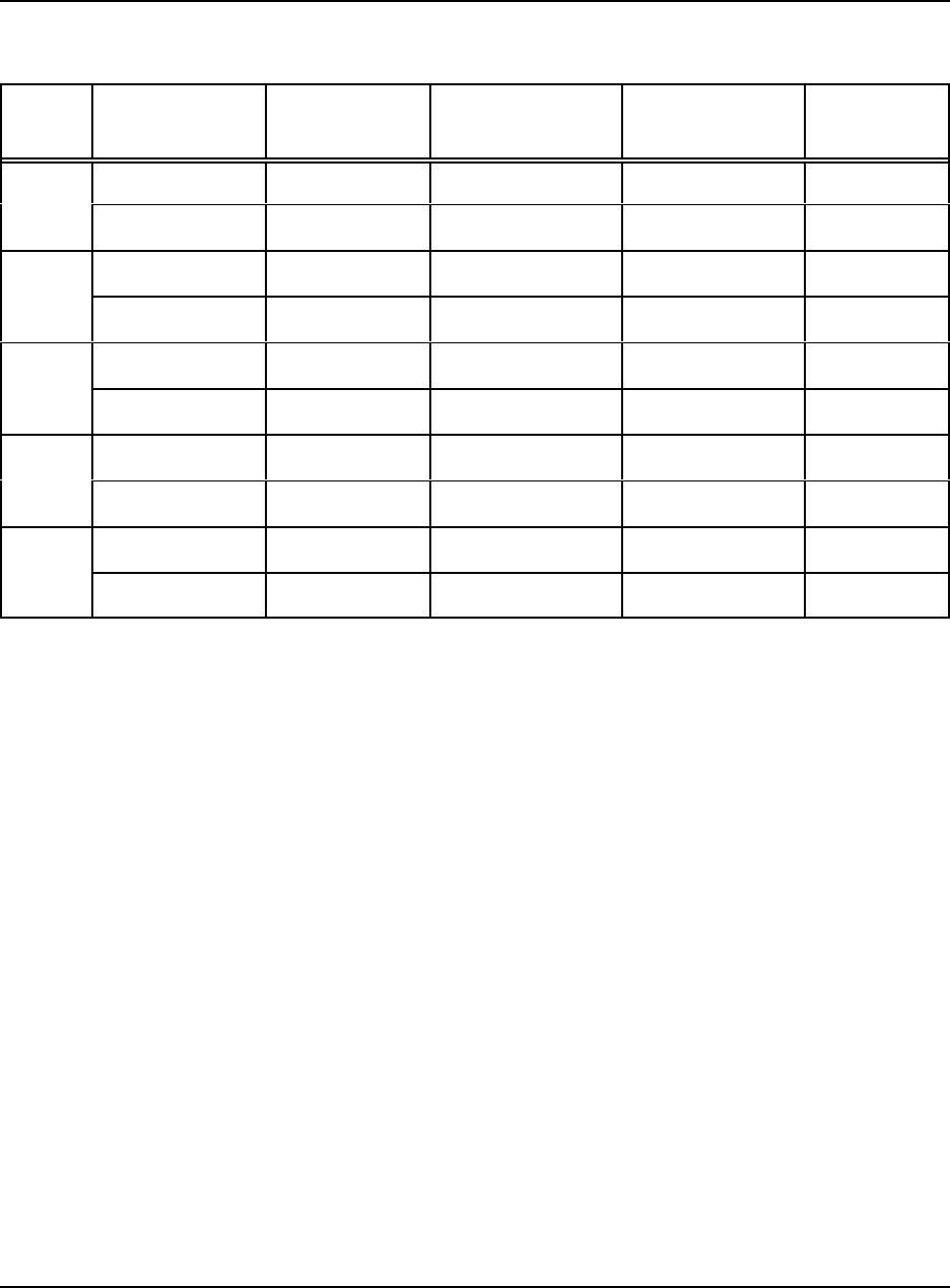
Table 5-l. Typical Opening/Closing Speed
Line
Size
Inches
Typical
Dead
Time
Setting
(Seconds)
Recommended Low Flow Set-point Typical
Opening
Speed
Adjust-
ment
(Turns
Open)
Typical
Opening
Time
(Shut-off
to Full
Open)
Seconds
Typical
Closing
Speed
Adjust-
ment
(Turns
Open)
Typical
Closing
Time
(Full
Open to
Shut-off)
Seconds
Turbine PD Meter
gpm K-factor gpm K-factor
2-3
4
6
8
0.015
0.015
0.030
0.030
100
150
150
150
50
25
25
25
100
150
150
150
100
25
25
25
0.25
0.25
0.75
0.75
5.0
5.0
5.0
5.0
0.75
0.75
1.25
1.25
2.0
2.0
2.0
2.0
DEC 2012 DANIEL MODEL 788DVC DIGITAL CONTROL VALVES
TM
DISASSEMBLY AND REASSEMBLY5-4
5.3 Cylinder Reassembly
Refer to Figure 5-2.
1. Inspect all O-rings for wear and damage and replace as required.
2. If removed, attach the cylinder head to the main cylinder body.
3. Insert the valve spring into the cylinder housing.
4. Inspect and position the piston into the cylinder housing.
5. Insert the fabricated sleeve over the valve piston and spring assembly. Once fully
compressed, block the spring following the procedure used in step 3 of the Disassembly
procedure.
6. Inspect and reposition the seat O-ring.
7. Replace seating and retaining ring. Once the entire retaining ring is in its’ groove, position
a punch or screwdriver over the end of the ring and tap sharply. This will seat the ring.
8. Again, using CAUTION, apply pressure to the valve piston and remove the block. Carefully
relieve the tension on the spring until it is properly resting against the seat ring.
9. Reinstall the cylinder assembly in the valve body being careful to properly seat O-rings and
secure in place using lock nuts.
Figure 5-2. Cylinder Assembly Removal

DANIEL MODEL 788DVC DIGITAL CONTROL VALVES DEC 2012
TM
DISASSEMBLY AND REASSEMBLY 5-5
5.4 Cup-seal Replacement on Existing “AP” Option Piston
If your Daniel Valve is being modified to accommodate applications requiring the use of aggressive
products used in petroleum blending operations, the following procedures should be followed in
retrofitting your valve.
Retrofit
5.4.1 To Replace Existing Standard Cylinder Assemblies with the Current Daniel “AP” Option:
a. Remove original cylinder assembly as shown in Section 5-1. The cylinder assembly
will be supplied from the factory with or without an indicator (specified on order).
b. Clean and inspect O-ring sealing surfaces in the main valve body. Apply a
lightweight lubricant to these surfaces before installing the new cylinder assembly.
c. Lower the “new” cylinder assembly and cylinder head into the valve body. Align the
bolt holes in the cylinder head with the studs in the main valve body.
d. Fasten the cylinder head into position using retaining nuts. Tighten nuts, alternating
to opposite sides, to assure a uniform seat.
e. Return all tubing and/or valve accessories to their original position.
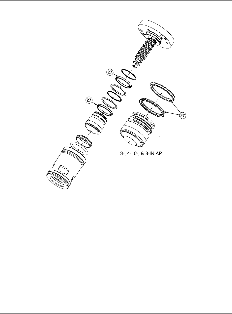
f. The cup-seals (27) should be protected at all times against damage or distortion of
any kind.
g. Proper installation dictates that cup-seals (27) be installed with the closed ends
facing “in”.
DEC 2012 DANIEL MODEL 788DVC DIGITAL CONTROL VALVES
TM
DISASSEMBLY AND REASSEMBLY5-6
Figure 5-3. Option Assembly
DANIEL MODEL 788DVC DIGITAL CONTROL VALVES DEC 2012
TM
DISASSEMBLY AND REASSEMBLY 5-7
5.4.2 To upgrade existing valves having the original “AP” option (received prior to September
1992), the following parts have been supplied as a separate kit:
- washers (29)
- Stat-O-Seals (30)
- one gasket (31)
- three O-rings (replaces existing O-rings (3) and (4) of the same part numbers.)
Reference Figure 7-1 for complete valve part numbers.
5.4.3 To upgrade existing “AP” units supplied prior to September, 1992:
a. Follow procedures described in Section 5-1 for general disassembly and Section 5-2
for Aggressive Products Cylinder disassembly.
b. Replace O-rings and install gasket, Stat-O-Seal and washers as required (reference
Figure 7-1).
c. Complete cylinder assembly by installing piston and all component parts through the
top of the cylinder housing.
Do not attempt to install the piston through the seat area. Attempts to assemble through the
seat area will destroy the spring-loaded Teflon cup-seals.
®
d. Secure cylinder assembly to cylinder heads using hand pressure or arbor press for
ease of installation.
DEC 2012 DANIEL MODEL 788DVC DIGITAL CONTROL VALVES
TM
DISASSEMBLY AND REASSEMBLY5-8
PERSONAL INJURY AND/OR EQUIPMENT DAMAGE
Caution is required when performing any disassembly procedure as the Cylinder head is
bolted to a spring loaded cylinder assembly. Service should only be performed by trained
and qualified service personnel.
Failure to comply with recommended could result in serious injury and/or damage to the
equipment.
e. Lower the “new” cylinder assembly and cylinder head into the valve body. Align the
bolt holes in the cylinder head with the studs in the main valve body.
f. Fasten the cylinder head into position using retaining nuts. Tighten nuts, alternating
to opposite sides, to assure a uniform seat.
g. Return all tubing and/or valve accessories to their original position.

DANIEL MODEL 788DVC DIGITAL CONTROL VALVES DEC 2012
TM
TROUBLESHOOTING 6-1
6.0 TROUBLESHOOTING
The most frequent problem encountered with any control valve is the accumulation of sediment,
rouge, scale and other foreign material in the pilot or its supply system. It is, therefore, good practice
to periodically remove the pilot from the valve and inspect it for accumulation of these materials.
The strainer and needle valve in the pilot supply line should also be flushed periodically to avoid
erratic control and slow response typical to obstructed flow. If sub-standard conditions persist after
thoroughly cleaning the system, examine the pilot for swollen o-rings.
Periodic examination of all seal and o-rings for nicks, cuts and wear is recommended. Reference
Section 5, Cylinder Disassembly/Reassembly.
DEC 2012 DANIEL MODEL 788DVC DIGITAL CONTROL VALVES
TM
TROUBLESHOOTING6-2
Table 6-1 provides information for identifying and correcting operational problems you may
experience with your control valve. Please keep in mind this information is not exhaustive and that
system abnormalities may result from causes other than valve error. This information is provided
to assist in general field repairs.
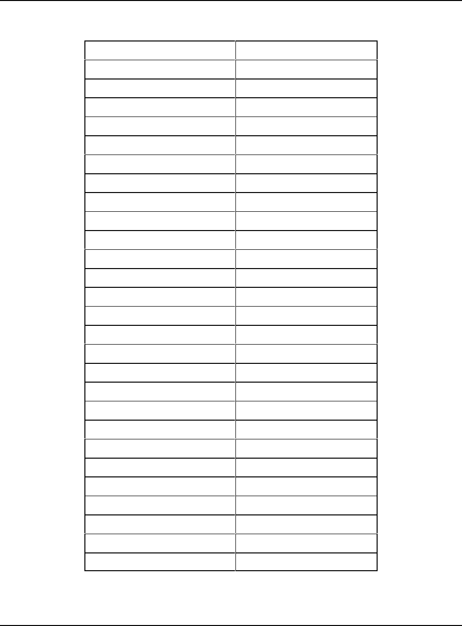
Table 6-1. Troubleshooting
Condition Probable Cause Correction
Valve will not open Upstream valve is closed. Open valve.
Pump is not operating. Start pump and check for cavitation.
Downstream valve is closed. Open valve. (Check coupler on bottom
loading units and internal valve in
truck.)
Insufficient pressure. Check pump. Check bypass and strainer
in line.
Clogged strainer. Clean strainer.
Swollen o-rings. Disassemble valve and replace o-rings.
Check compatibility of o-rings with
product.
Pilot malfunction. Consult pilot manual.
Valve opens too slowly Valve inlet pressure below normal. Check strainer and pump for
obstruction.
Swollen o-rings. Disassemble valve and replace o-rings.
Check compatibility of o-rings with
product.
Pilot malfunction. Consult pilot manual.
Valve will not close off tightly Bent indicator stem. Replace indicator
Foreign material lodged in main
valve piston seat.
Disassemble valve and inspect piston.
Swollen o-rings Disassemble valve and replace o-rings.
Check compatibility of o-rings with
product.
Piston or seat o-ring cut or
defective.
Disassemble valve and replace, if
necessary.
Pilot malfunction. Consult pilot manual.

DANIEL MODEL 788DVC DIGITAL CONTROL VALVES DEC 2012
TM
PARTS LIST 7-1
7.0 PARTS LIST
Table 7-1 lists the replacement parts for 2- through 6-inch Model V2700-20 Series Control Valves.
The item numbers in the parts list (Table 7-1) correspond with the sequence numbers in Figure 7-1.
This section contains the necessary parts required to assemble any standard unit that is covered in
this manual. Recommended spare parts have been indicated using an asterisk before the item
number. All part numbers shown reflect standard materials of construction. For other materials of
construction, special requirements or part numbers not listed, consult the factory.
TRADEMARKS:
Daniel ......................
TM Daniel, a division of Emerson Process Management
Kalrez ................................
®E.I. du Pont de Nemours and Company
Teflon ................................
®E.I. du Pont de Nemours and Company
Viton .................................
®E.I. du Pont de Nemours and Company
When ordering replacement parts you must furnish the following information:
• Valve serial number
• Part number, if available
• Part description
• Quantity required.
To order replacement parts, contact your Daniel sales representative.

DEC 2012 DANIEL MODEL 788DVC DIGITAL CONTROL VALVES
TM
PARTS LIST7-2
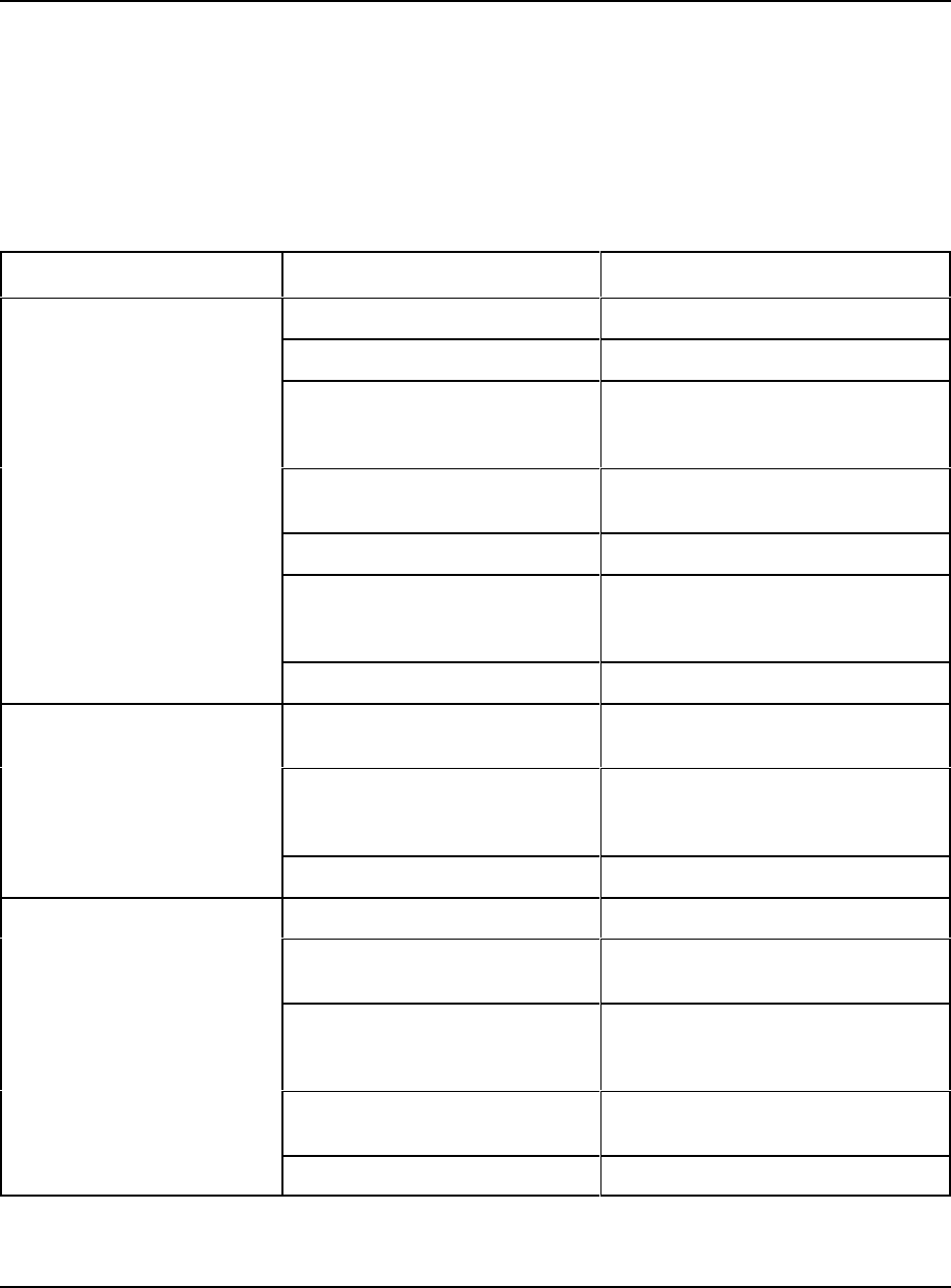
Table 7-1. Parts List - 2", 3", 4", 6", 8" Sizes
Item Description Qty 2-inch 3-inch 4-inch 6-inch 8-inch
1 valve body - in line
150 ANSI steel
1 521001 531001 541001 561001 581001
2 solenoid (N.C.)
110/50, 120/60
220/50, 240/60
1
456800-612
456800-621
456800-612
456800-621
456800-612
456800-621
456800-612
456800-621
456800-612
456800-621
3 junction box 1
4 solenoid (N.O.)
110/50, 120/60
220/50, 240/60
1
456815-012
456815-022
456815-012
456815-022
456815-012
456815-022
456815-012
456815-022
456815-012
456815-022
5 needle valve 460385-522 460385-522 460385-522 460385-522 460385-522
6 strainer assembly 2 530245 530245 530245 530245 530245
9 indicator 1 consult
factory
10 mounting screws 1 consult
factory
11 cylinder assembly
(std. Construction
w/Viton Dynamic
®
O-rings)
1 520065-421 530065-421 640065-421 560065-421 580065-421
12 cylinder head 1 520056-500 530056-500 540056-500 560056-500 580056-500
13 cylinder 1 520471-400 530471-400 540471-400 560471-400 580471-400
14 valve spring
Std. Med. (5-10 psi)
light (4-6 psi)
heavy (10-30 psi)
1
520029
520031
520059
530029
530031
530059
540029
540031
540059
560029
560031
560059
580029
580031
580059
15 piston
stainless steel
1 520084-600 150333 150333 150333 CF
16 sealing ring 1 520026-500 152048-120 152048-120 152048-120 152048-120
17 retaining ring
18 socket screw 3 151001-019 151001-019 151042 151042 151042
19 O-ring/Buna-N
O-ring/Viton®
O-ring/EPR
1 152073
152073-022
152073-005
152075
152075-022
152075-005
152078
152078-022
152078-005
157002
157002-022
157002-005
157005
CF
CF
20 O-ring/Buna-N
O-ring/Viton®
O-ring/EPR
1 152085
152085-022
152085-005
152100
152100-022
152100-022
152080
152080-022
152080-005
157003
157003-022
157003-005
157006
CF
CF
DANIEL MODEL 788DVC DIGITAL CONTROL VALVES DEC 2012
TM
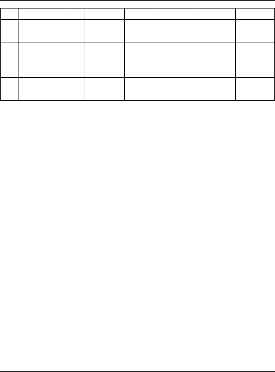
Item Description Qty 2-inch 3-inch 4-inch 6-inch 8-inch
PARTS LIST 7-3
21 O-ring/Buna-N
O-ring/Viton®
O-ring/EPR
1 ---
---
---
157079
157079-022
157079-005
150727
157078-022
157078-005
150727
157061-022
157061-005
CF
CF
CF
22 O-ring/Buna-N
O-ring/Viton®
O-ring/EPR
1 ---
---
---
152067
152067-022
152067-055
152070
152070-022
152070-005
152070
152070-022
152070-005
CF
CF
CF
23 seal spacer 530028 ---- ---- ----
24 O-ring/Buna-N
O-ring/Viton®
O-ring/EPR
152061
152061-022
152061-005
152095
152095-022
152095-005
152094
152094-022
152094-005
152079-022
152079-022
152079-005
CF
CF
CF
* Recommended Spare Parts
DEC 2012 DANIEL MODEL 788DVC DIGITAL CONTROL VALVES
TM
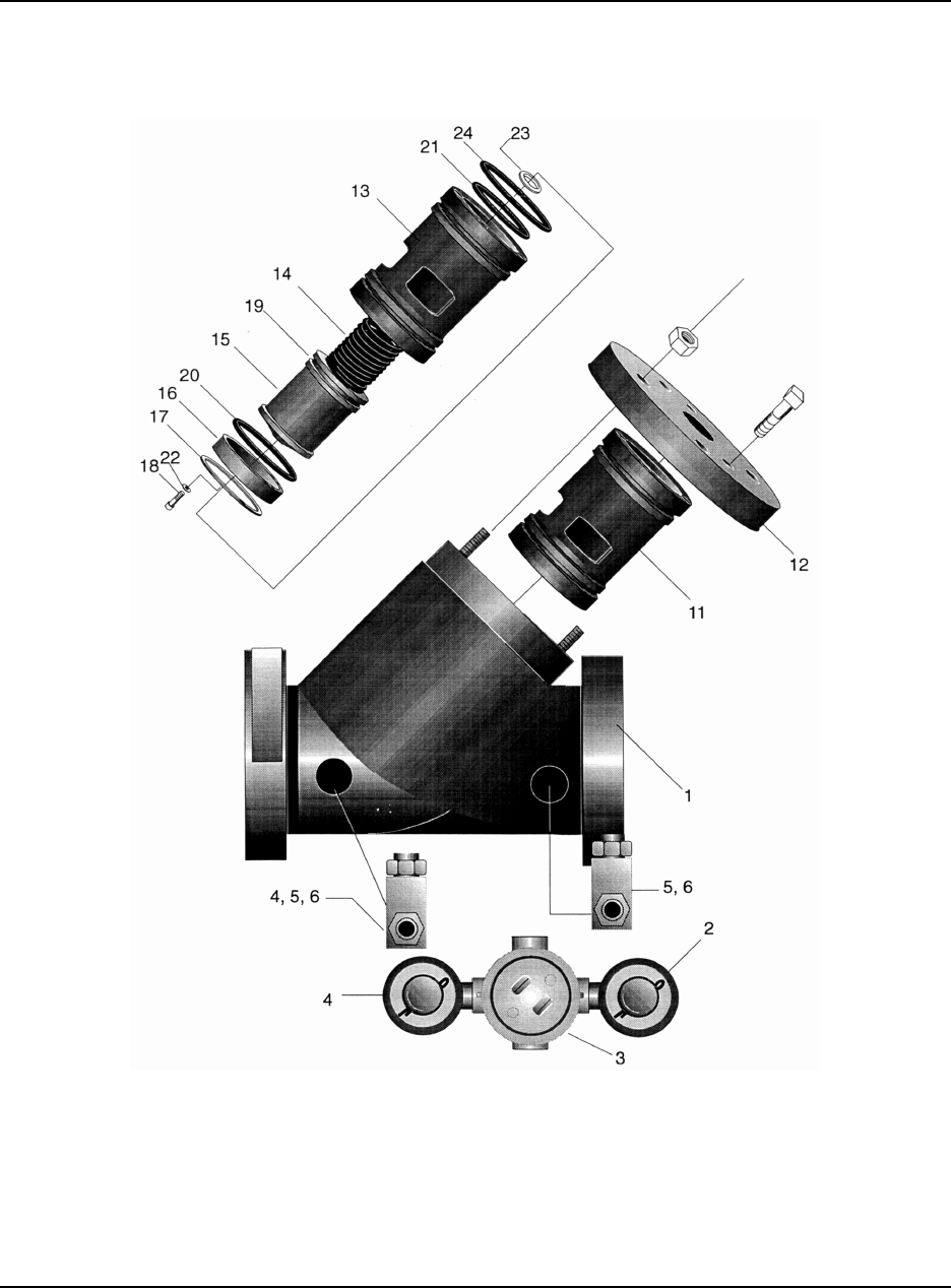
PARTS LIST7-4
Figure 7-1. Valve Cylinder Assembly

Daniel Measurement and Control, Inc.
TM
Returned Material Authorization
Repair Form for Used Equipment
Including Decontamination/Cleaning Statement
A Return Material Authorization (RMA) number must be obtained prior to returning any equipment
for any reason. Download the RMA form from the Support Services web page by selecting the link
below.
http://www2.emersonprocess.com/EN-US/BRANDS/DANIEL/SUPPORT-SERVICES/Pages/Support-Services.aspx
1. Return Material Authorization (RMA) Number ____________________________________
2. Equipment to be returned:
Model Number _________________________ Serial Number _______________________
3. Reason for return: ___________________________________________________________
___________________________________________________________________________
___________________________________________________________________________
________________________________________________________________________
Decontamination/Cleaning Fluids Process
A. List each substance in which the equipment was exposed. Attach additional documents if necessary.
Common
Name
CAS# if
available
Used for Hazardous
Waste (20 CFR 261)
EPA Waste Code
if used for hazardous waste
[ ] Yes [ ] No
[ ] Yes [ ] No
[ ] Yes [ ] No
[ ] Yes [ ] No
[ ] Yes [ ] No
[ ] Yes [ ] No
B. Circle any hazards and/or process fluid types that apply:
Infectious Radioactive Explosive Pyrophoric Poison Gas
Cyanides Sulfides CorrosiveOxidizer Flammable Poison
Carcinogen Peroxide Reactive-Air Reactive-Water Reactive-Other (list)
Other hazard category (list):
C. Describe decontamination/cleaning process. Include MSDS description for substances used in decontamination and
cleaning processes. Attach additional documents if necessary.
Shipping Requirements
Failure to comply with this procedure will result in the shipment being refused.
1. Write the RMA number on the shipping package.
2. Inside the package include one copy of this document and all required Material Safety Data
Sheets (MSDS)
3. Outside of the package attach one copy of this document and all required Material Safety Data
Sheets (MSDS).
THIS EQUIPMENT, BEING RETURNED “FOR REPAIR,” HAS BEEN COMPLETELY
DECONTAMINATED AND CLEANED. ALL FOREIGN SUBSTANCES HAVE BEEN
DOCUMENTED ABOVE AND MSDS SHEETS ARE ATTACHED.
By:
(Signature) (Print name)
Title: Date:
Company:
Phone: Fax:

Emerson Process Management
Daniel Measurement and Control, Inc.
11100 Brittmoore Park Drive
Houston, TX 77041
T+1 713-467-6000
F+1 713-827-4805
www.emerson.com
Copyright© 2012
Daniel Measurement and Control, Inc. and Daniel Measurement Services, Inc. Divisions of Emerson Process Management reserve the right
to make changes to any of its products or services at any time without prior notification in order to improve that product or service and to
supply the best product or service possible.
Daniel Measurement Services, Inc. offers both on-call and contract maintenance service designed to provide single-source
responsibility for all Daniel products. The sales and service offices of Daniel Measurement and Control, Inc. are located throughout the
United States and in major countries overseas. For the location of the sales or service office nearest you, telephone the number below
or visit the Daniel Measurement and Control, Inc. website.
T+1713-827-6314
F+1713-827-4805
www.emerson.com
