Emerson Liebert Fs Dc Users Manual
2015-01-05
: Emerson Emerson-Liebert-Fs-Dc-Users-Manual-165410 emerson-liebert-fs-dc-users-manual-165410 emerson pdf
Open the PDF directly: View PDF ![]() .
.
Page Count: 168 [warning: Documents this large are best viewed by clicking the View PDF Link!]
AC Power
For Business-Critical Continuity™
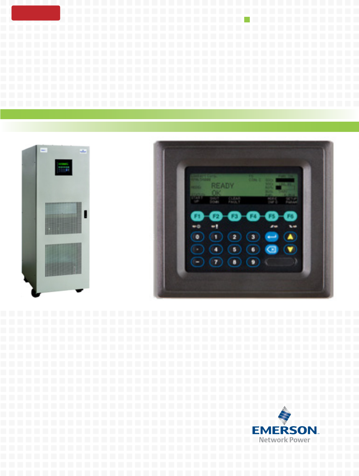
Liebert® FS™ DC Energy Storage System
User Manual - 200kW/12 Seconds, 540VDC
DISCONTINUED
PRODUCT

DISCONTINUED
PROD UC T

i
TABLE OF CONTENTS
IMPORTANT SAFETY INSTRUCTIONS . . . . . . . . . . . . . . . . . . . . . . . . . . . . . . . . . . . . . . . . . . . . . . . .1
1.0 GENERAL SYSTEM INFORMATION . . . . . . . . . . . . . . . . . . . . . . . . . . . . . . . . . . . . . . . . . . . .3
1.1 General Information. . . . . . . . . . . . . . . . . . . . . . . . . . . . . . . . . . . . . . . . . . . . . . . . . . . . . . . . . . 3
1.1.1 Safety Considerations. . . . . . . . . . . . . . . . . . . . . . . . . . . . . . . . . . . . . . . . . . . . . . . . . . . . . . . . . . 3
1.1.2 Requesting Assistance from Liebert . . . . . . . . . . . . . . . . . . . . . . . . . . . . . . . . . . . . . . . . . . . . . . 3
1.2 General System Description . . . . . . . . . . . . . . . . . . . . . . . . . . . . . . . . . . . . . . . . . . . . . . . . . . . 4
1.2.1 General Specifications . . . . . . . . . . . . . . . . . . . . . . . . . . . . . . . . . . . . . . . . . . . . . . . . . . . . . . . . . 6
1.2.2 Features and Benefits . . . . . . . . . . . . . . . . . . . . . . . . . . . . . . . . . . . . . . . . . . . . . . . . . . . . . . . . . 7
1.2.3 Applicable Standards and Certification . . . . . . . . . . . . . . . . . . . . . . . . . . . . . . . . . . . . . . . . . . . 7
2.0 SITE PREPARATION . . . . . . . . . . . . . . . . . . . . . . . . . . . . . . . . . . . . . . . . . . . . . . . . . . . . .10
2.1 System Location . . . . . . . . . . . . . . . . . . . . . . . . . . . . . . . . . . . . . . . . . . . . . . . . . . . . . . . . . . . . 10
2.2 Environmental Considerations . . . . . . . . . . . . . . . . . . . . . . . . . . . . . . . . . . . . . . . . . . . . . . . . 10
2.3 Flooring Requirements. . . . . . . . . . . . . . . . . . . . . . . . . . . . . . . . . . . . . . . . . . . . . . . . . . . . . . . 11
2.3.1 Floor Loading . . . . . . . . . . . . . . . . . . . . . . . . . . . . . . . . . . . . . . . . . . . . . . . . . . . . . . . . . . . . . . . 11
2.3.2 Floor-Space Occupation . . . . . . . . . . . . . . . . . . . . . . . . . . . . . . . . . . . . . . . . . . . . . . . . . . . . . . . 11
2.3.3 Clearances. . . . . . . . . . . . . . . . . . . . . . . . . . . . . . . . . . . . . . . . . . . . . . . . . . . . . . . . . . . . . . . . . . 11
2.4 Electrical Considerations . . . . . . . . . . . . . . . . . . . . . . . . . . . . . . . . . . . . . . . . . . . . . . . . . . . . . 11
2.4.1 DC Power Connections . . . . . . . . . . . . . . . . . . . . . . . . . . . . . . . . . . . . . . . . . . . . . . . . . . . . . . . . 11
2.4.2 Status/Control Connections . . . . . . . . . . . . . . . . . . . . . . . . . . . . . . . . . . . . . . . . . . . . . . . . . . . . 12
2.4.3 Grounding Connections . . . . . . . . . . . . . . . . . . . . . . . . . . . . . . . . . . . . . . . . . . . . . . . . . . . . . . . 12
2.4.4 AC Power Connections . . . . . . . . . . . . . . . . . . . . . . . . . . . . . . . . . . . . . . . . . . . . . . . . . . . . . . . . 12
2.4.5 Remote Monitoring Connections—Optional . . . . . . . . . . . . . . . . . . . . . . . . . . . . . . . . . . . . . . . 12
3.0 UNLOADING AND UNPACKING . . . . . . . . . . . . . . . . . . . . . . . . . . . . . . . . . . . . . . . . . . . . . .13
3.1 Inspection Before Removal From the Truck . . . . . . . . . . . . . . . . . . . . . . . . . . . . . . . . . . . . . . 13
3.2 Unloading . . . . . . . . . . . . . . . . . . . . . . . . . . . . . . . . . . . . . . . . . . . . . . . . . . . . . . . . . . . . . . . . . 13
3.2.1 Handling . . . . . . . . . . . . . . . . . . . . . . . . . . . . . . . . . . . . . . . . . . . . . . . . . . . . . . . . . . . . . . . . . . . 14
3.2.2 Unpacking . . . . . . . . . . . . . . . . . . . . . . . . . . . . . . . . . . . . . . . . . . . . . . . . . . . . . . . . . . . . . . . . . . 14
3.3 Positioning the Liebert FS . . . . . . . . . . . . . . . . . . . . . . . . . . . . . . . . . . . . . . . . . . . . . . . . . . . . 16
3.3.1 Moving the Liebert FS . . . . . . . . . . . . . . . . . . . . . . . . . . . . . . . . . . . . . . . . . . . . . . . . . . . . . . . . 16
3.3.2 Storing the Liebert FS for Delayed Installation . . . . . . . . . . . . . . . . . . . . . . . . . . . . . . . . . . . . 16
4.0 INSTALLATION . . . . . . . . . . . . . . . . . . . . . . . . . . . . . . . . . . . . . . . . . . . . . . . . . . . . . . . . .17
4.1 Cabinet Floor Mounting. . . . . . . . . . . . . . . . . . . . . . . . . . . . . . . . . . . . . . . . . . . . . . . . . . . . . . 19
4.1.1 Concrete, Masonry or Stone Floor Mounting . . . . . . . . . . . . . . . . . . . . . . . . . . . . . . . . . . . . . . 20
4.1.2 Wood Floor Mounting . . . . . . . . . . . . . . . . . . . . . . . . . . . . . . . . . . . . . . . . . . . . . . . . . . . . . . . . . 24
4.1.3 Raised Floor Mounting . . . . . . . . . . . . . . . . . . . . . . . . . . . . . . . . . . . . . . . . . . . . . . . . . . . . . . . . 25
4.2 Wiring Connections . . . . . . . . . . . . . . . . . . . . . . . . . . . . . . . . . . . . . . . . . . . . . . . . . . . . . . . . . 26
4.2.1 General Wiring Considerations . . . . . . . . . . . . . . . . . . . . . . . . . . . . . . . . . . . . . . . . . . . . . . . . . 26
4.2.2 DC Power Connections . . . . . . . . . . . . . . . . . . . . . . . . . . . . . . . . . . . . . . . . . . . . . . . . . . . . . . . . 28
4.2.3 Status/Control Connections . . . . . . . . . . . . . . . . . . . . . . . . . . . . . . . . . . . . . . . . . . . . . . . . . . . . 28
4.2.4 Ground Connections . . . . . . . . . . . . . . . . . . . . . . . . . . . . . . . . . . . . . . . . . . . . . . . . . . . . . . . . . . 28
4.2.5 AC Auxiliary Control Power Supply Connections . . . . . . . . . . . . . . . . . . . . . . . . . . . . . . . . . . 29
4.2.6 Remote Monitoring Connections—Optional . . . . . . . . . . . . . . . . . . . . . . . . . . . . . . . . . . . . . . . 31
4.3 Startup Considerations . . . . . . . . . . . . . . . . . . . . . . . . . . . . . . . . . . . . . . . . . . . . . . . . . . . . . . 31
DISCONTINUED
PROD UC T

ii
5.0 SYSTEM OVERVIEW . . . . . . . . . . . . . . . . . . . . . . . . . . . . . . . . . . . . . . . . . . . . . . . . . . . . .32
5.1 Detailed System Description . . . . . . . . . . . . . . . . . . . . . . . . . . . . . . . . . . . . . . . . . . . . . . . . . . 32
5.1.1 System Module Description . . . . . . . . . . . . . . . . . . . . . . . . . . . . . . . . . . . . . . . . . . . . . . . . . . . . 33
5.1.2 Power System . . . . . . . . . . . . . . . . . . . . . . . . . . . . . . . . . . . . . . . . . . . . . . . . . . . . . . . . . . . . . . . 34
5.1.3 System Performance. . . . . . . . . . . . . . . . . . . . . . . . . . . . . . . . . . . . . . . . . . . . . . . . . . . . . . . . . . 34
5.1.4 User interfaces . . . . . . . . . . . . . . . . . . . . . . . . . . . . . . . . . . . . . . . . . . . . . . . . . . . . . . . . . . . . . . 35
5.1.5 UPS Interconnection Kit . . . . . . . . . . . . . . . . . . . . . . . . . . . . . . . . . . . . . . . . . . . . . . . . . . . . . . 35
5.1.6 Power Conversion Module . . . . . . . . . . . . . . . . . . . . . . . . . . . . . . . . . . . . . . . . . . . . . . . . . . . . . 36
5.1.7 Magnetic Levitation Module (MLM) . . . . . . . . . . . . . . . . . . . . . . . . . . . . . . . . . . . . . . . . . . . . . 37
5.1.8 Flywheel Module. . . . . . . . . . . . . . . . . . . . . . . . . . . . . . . . . . . . . . . . . . . . . . . . . . . . . . . . . . . . . 38
5.1.9 Rotor/Flywheel—Rotating Group . . . . . . . . . . . . . . . . . . . . . . . . . . . . . . . . . . . . . . . . . . . . . . . 39
5.1.10 Motor Generator . . . . . . . . . . . . . . . . . . . . . . . . . . . . . . . . . . . . . . . . . . . . . . . . . . . . . . . . . . . . . 39
5.1.11 Vacuum System . . . . . . . . . . . . . . . . . . . . . . . . . . . . . . . . . . . . . . . . . . . . . . . . . . . . . . . . . . . . . 40
5.1.12 Flywheel Sensors . . . . . . . . . . . . . . . . . . . . . . . . . . . . . . . . . . . . . . . . . . . . . . . . . . . . . . . . . . . . 41
5.1.13 System Safety . . . . . . . . . . . . . . . . . . . . . . . . . . . . . . . . . . . . . . . . . . . . . . . . . . . . . . . . . . . . . . . 42
5.1.14 Cabinet . . . . . . . . . . . . . . . . . . . . . . . . . . . . . . . . . . . . . . . . . . . . . . . . . . . . . . . . . . . . . . . . . . . . 42
5.1.15 Ventilation and Cooling . . . . . . . . . . . . . . . . . . . . . . . . . . . . . . . . . . . . . . . . . . . . . . . . . . . . . . . 43
5.2 List of System User-Configurable Parameters. . . . . . . . . . . . . . . . . . . . . . . . . . . . . . . . . . . . 43
5.3 Modes of Operation. . . . . . . . . . . . . . . . . . . . . . . . . . . . . . . . . . . . . . . . . . . . . . . . . . . . . . . . . . 45
5.3.1 OFF Mode . . . . . . . . . . . . . . . . . . . . . . . . . . . . . . . . . . . . . . . . . . . . . . . . . . . . . . . . . . . . . . . . . . 46
5.3.2 STANDBY Mode . . . . . . . . . . . . . . . . . . . . . . . . . . . . . . . . . . . . . . . . . . . . . . . . . . . . . . . . . . . . . 46
5.3.3 STARTUP Mode . . . . . . . . . . . . . . . . . . . . . . . . . . . . . . . . . . . . . . . . . . . . . . . . . . . . . . . . . . . . . 46
5.3.4 CHARGE Mode . . . . . . . . . . . . . . . . . . . . . . . . . . . . . . . . . . . . . . . . . . . . . . . . . . . . . . . . . . . . . . 47
5.3.5 READY Mode . . . . . . . . . . . . . . . . . . . . . . . . . . . . . . . . . . . . . . . . . . . . . . . . . . . . . . . . . . . . . . . 47
5.3.6 DISCHARGE Mode . . . . . . . . . . . . . . . . . . . . . . . . . . . . . . . . . . . . . . . . . . . . . . . . . . . . . . . . . . 48
5.3.7 SHUTDOWN Mode . . . . . . . . . . . . . . . . . . . . . . . . . . . . . . . . . . . . . . . . . . . . . . . . . . . . . . . . . . 48
5.3.8 COAST Mode . . . . . . . . . . . . . . . . . . . . . . . . . . . . . . . . . . . . . . . . . . . . . . . . . . . . . . . . . . . . . . . 49
5.3.9 FAULT Mode . . . . . . . . . . . . . . . . . . . . . . . . . . . . . . . . . . . . . . . . . . . . . . . . . . . . . . . . . . . . . . . 49
5.4 Maintenance and Reliability . . . . . . . . . . . . . . . . . . . . . . . . . . . . . . . . . . . . . . . . . . . . . . . . . . 51
6.0 OPERATION . . . . . . . . . . . . . . . . . . . . . . . . . . . . . . . . . . . . . . . . . . . . . . . . . . . . . . . . . . .52
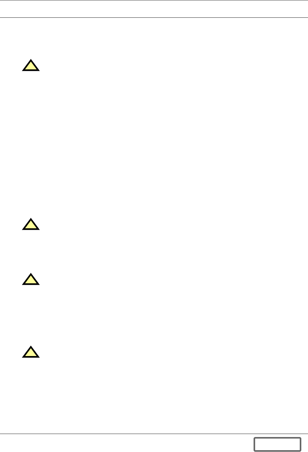
6.1 Operator Controls. . . . . . . . . . . . . . . . . . . . . . . . . . . . . . . . . . . . . . . . . . . . . . . . . . . . . . . . . . . 52
6.2 Control Panel . . . . . . . . . . . . . . . . . . . . . . . . . . . . . . . . . . . . . . . . . . . . . . . . . . . . . . . . . . . . . . 53
6.2.1 Main screen function descriptions . . . . . . . . . . . . . . . . . . . . . . . . . . . . . . . . . . . . . . . . . . . . . . . 54
6.2.2 System MODE Indicators . . . . . . . . . . . . . . . . . . . . . . . . . . . . . . . . . . . . . . . . . . . . . . . . . . . . . 55
6.2.3 System STATUS Indicators . . . . . . . . . . . . . . . . . . . . . . . . . . . . . . . . . . . . . . . . . . . . . . . . . . . . 55
6.2.4 Other Status Indicators . . . . . . . . . . . . . . . . . . . . . . . . . . . . . . . . . . . . . . . . . . . . . . . . . . . . . . . 56
6.3 Security Access . . . . . . . . . . . . . . . . . . . . . . . . . . . . . . . . . . . . . . . . . . . . . . . . . . . . . . . . . . . . . 57
6.3.1 Security Levels . . . . . . . . . . . . . . . . . . . . . . . . . . . . . . . . . . . . . . . . . . . . . . . . . . . . . . . . . . . . . . 57
6.3.2 Password . . . . . . . . . . . . . . . . . . . . . . . . . . . . . . . . . . . . . . . . . . . . . . . . . . . . . . . . . . . . . . . . . . . 57
6.3.3 EPROM (System) Parameters . . . . . . . . . . . . . . . . . . . . . . . . . . . . . . . . . . . . . . . . . . . . . . . . . . 57
DISCONTINUED
PROD UC T

iii
6.4 Menu Tree and Navigation . . . . . . . . . . . . . . . . . . . . . . . . . . . . . . . . . . . . . . . . . . . . . . . . . . . 57
6.4.1 Screen Tree Menu Functions . . . . . . . . . . . . . . . . . . . . . . . . . . . . . . . . . . . . . . . . . . . . . . . . . . . 57
6.4.2 Navigation and Operation of Control Panel . . . . . . . . . . . . . . . . . . . . . . . . . . . . . . . . . . . . . . . 59
6.4.3 System Setup and Parameter Access . . . . . . . . . . . . . . . . . . . . . . . . . . . . . . . . . . . . . . . . . . . . 59
6.4.4 View. . . . . . . . . . . . . . . . . . . . . . . . . . . . . . . . . . . . . . . . . . . . . . . . . . . . . . . . . . . . . . . . . . . . . . . 61
6.4.5 Time/Date . . . . . . . . . . . . . . . . . . . . . . . . . . . . . . . . . . . . . . . . . . . . . . . . . . . . . . . . . . . . . . . . . . 61
6.4.6 Temperatures . . . . . . . . . . . . . . . . . . . . . . . . . . . . . . . . . . . . . . . . . . . . . . . . . . . . . . . . . . . . . . . 62
6.4.7 Voltages. . . . . . . . . . . . . . . . . . . . . . . . . . . . . . . . . . . . . . . . . . . . . . . . . . . . . . . . . . . . . . . . . . . . 62
6.4.8 History. . . . . . . . . . . . . . . . . . . . . . . . . . . . . . . . . . . . . . . . . . . . . . . . . . . . . . . . . . . . . . . . . . . . . 62
6.4.9 Options . . . . . . . . . . . . . . . . . . . . . . . . . . . . . . . . . . . . . . . . . . . . . . . . . . . . . . . . . . . . . . . . . . . . 64
6.4.10 Network—Requires DCM Option . . . . . . . . . . . . . . . . . . . . . . . . . . . . . . . . . . . . . . . . . . . . . . . 65
6.4.11 Electrical . . . . . . . . . . . . . . . . . . . . . . . . . . . . . . . . . . . . . . . . . . . . . . . . . . . . . . . . . . . . . . . . . . . 66
6.4.12 Vitals . . . . . . . . . . . . . . . . . . . . . . . . . . . . . . . . . . . . . . . . . . . . . . . . . . . . . . . . . . . . . . . . . . . . . . 66
6.4.13 Security . . . . . . . . . . . . . . . . . . . . . . . . . . . . . . . . . . . . . . . . . . . . . . . . . . . . . . . . . . . . . . . . . . . . 66
6.4.14 About . . . . . . . . . . . . . . . . . . . . . . . . . . . . . . . . . . . . . . . . . . . . . . . . . . . . . . . . . . . . . . . . . . . . . . 68
6.4.15 Tools . . . . . . . . . . . . . . . . . . . . . . . . . . . . . . . . . . . . . . . . . . . . . . . . . . . . . . . . . . . . . . . . . . . . . . 68
6.5 System Startup. . . . . . . . . . . . . . . . . . . . . . . . . . . . . . . . . . . . . . . . . . . . . . . . . . . . . . . . . . . . . 69
6.5.1 Initial System Startup Procedure . . . . . . . . . . . . . . . . . . . . . . . . . . . . . . . . . . . . . . . . . . . . . . . 69
6.5.2 Inspection before Initial System Startup . . . . . . . . . . . . . . . . . . . . . . . . . . . . . . . . . . . . . . . . . 69
6.5.3 Control Parameters Setup at Initial System Startup . . . . . . . . . . . . . . . . . . . . . . . . . . . . . . . 70
6.5.4 Initial System Startup Procedure . . . . . . . . . . . . . . . . . . . . . . . . . . . . . . . . . . . . . . . . . . . . . . . 70
6.5.5 Regular Startup Procedure . . . . . . . . . . . . . . . . . . . . . . . . . . . . . . . . . . . . . . . . . . . . . . . . . . . . 71
6.5.6 Inspection Before Regular Startup . . . . . . . . . . . . . . . . . . . . . . . . . . . . . . . . . . . . . . . . . . . . . . 71
6.5.7 Starting up the System . . . . . . . . . . . . . . . . . . . . . . . . . . . . . . . . . . . . . . . . . . . . . . . . . . . . . . . 71
6.6 Shutdown Procedure . . . . . . . . . . . . . . . . . . . . . . . . . . . . . . . . . . . . . . . . . . . . . . . . . . . . . . . . 72
7.0 MAINTENANCE . . . . . . . . . . . . . . . . . . . . . . . . . . . . . . . . . . . . . . . . . . . . . . . . . . . . . . . . .73
7.1 Safety Precautions . . . . . . . . . . . . . . . . . . . . . . . . . . . . . . . . . . . . . . . . . . . . . . . . . . . . . . . . . . 73
7.2 Liebert Services . . . . . . . . . . . . . . . . . . . . . . . . . . . . . . . . . . . . . . . . . . . . . . . . . . . . . . . . . . . . 74
7.3 Routine Maintenance . . . . . . . . . . . . . . . . . . . . . . . . . . . . . . . . . . . . . . . . . . . . . . . . . . . . . . . . 74
7.4 Maintenance Schedule . . . . . . . . . . . . . . . . . . . . . . . . . . . . . . . . . . . . . . . . . . . . . . . . . . . . . . . 75
7.5 Record Log . . . . . . . . . . . . . . . . . . . . . . . . . . . . . . . . . . . . . . . . . . . . . . . . . . . . . . . . . . . . . . . . 75
7.6 Optional Air Filters . . . . . . . . . . . . . . . . . . . . . . . . . . . . . . . . . . . . . . . . . . . . . . . . . . . . . . . . . 76
7.7 Torque Requirements. . . . . . . . . . . . . . . . . . . . . . . . . . . . . . . . . . . . . . . . . . . . . . . . . . . . . . . . 76
7.8 Detecting Trouble . . . . . . . . . . . . . . . . . . . . . . . . . . . . . . . . . . . . . . . . . . . . . . . . . . . . . . . . . . . 76
7.9 Reporting a Problem. . . . . . . . . . . . . . . . . . . . . . . . . . . . . . . . . . . . . . . . . . . . . . . . . . . . . . . . . 77
7.10 Corrective Actions . . . . . . . . . . . . . . . . . . . . . . . . . . . . . . . . . . . . . . . . . . . . . . . . . . . . . . . . . . 77
7.11 Recommended Test Equipment . . . . . . . . . . . . . . . . . . . . . . . . . . . . . . . . . . . . . . . . . . . . . . . . 77
7.12 Limited Life Components. . . . . . . . . . . . . . . . . . . . . . . . . . . . . . . . . . . . . . . . . . . . . . . . . . . . . 77
8.0 TROUBLESHOOTING . . . . . . . . . . . . . . . . . . . . . . . . . . . . . . . . . . . . . . . . . . . . . . . . . . . . .78
8.1 General . . . . . . . . . . . . . . . . . . . . . . . . . . . . . . . . . . . . . . . . . . . . . . . . . . . . . . . . . . . . . . . . . . . 78
8.2 Warnings. . . . . . . . . . . . . . . . . . . . . . . . . . . . . . . . . . . . . . . . . . . . . . . . . . . . . . . . . . . . . . . . . . 79
8.3 Faults . . . . . . . . . . . . . . . . . . . . . . . . . . . . . . . . . . . . . . . . . . . . . . . . . . . . . . . . . . . . . . . . . . . . 81
DISCONTINUED
PROD UC T

iv
APPENDIX A.0 UPS INTERCONNECTION KITS. . . . . . . . . . . . . . . . . . . . . . . . . . . . . . . . . . . . . .84
Appendix A.1 Wiring Connections . . . . . . . . . . . . . . . . . . . . . . . . . . . . . . . . . . . . . . . . . . . . . . . . 84
Appendix A.1.1 General Wiring Considerations. . . . . . . . . . . . . . . . . . . . . . . . . . . . . . . . . . . . . . . . . . . . 84
Appendix A.1.2 DC Power Connections. . . . . . . . . . . . . . . . . . . . . . . . . . . . . . . . . . . . . . . . . . . . . . . . . . . 86
Appendix A.2 Installing the Liebert FS With a Liebert Series 610, Liebert Series 600T or Liebert
Series 60087
Appendix A.2.1 Description - Liebert Series 610/600T/600 UPS Interconnection Kit . . . . . . . . . . . . . . 87
Appendix A.2.2 Status/Control Connections - Liebert Series 610/600T/600 UPS Interconnection Kit. 88
Appendix A.2.3 UPS Configuration - Liebert FS and Liebert Series 610, 600T or 600 . . . . . . . . . . . . . 88
Appendix A.2.4 Liebert FS Configuration - Single Liebert FS on Liebert Series 610/600T/600 DC Bus89
Appendix A.2.5 Liebert FS Configuration - Multiple Liebert FS Units on Liebert Series 610/600T/600
DC Bus89
Appendix A.3 Installing the Liebert FS With a Liebert Npower UPS . . . . . . . . . . . . . . . . . . . . 90
Appendix A.3.1 Description - Liebert Npower UPS Interconnection Kit . . . . . . . . . . . . . . . . . . . . . . . . 90
Appendix A.3.2 Status/Control Connections - Liebert Npower UPS Interconnection Kit . . . . . . . . . . . 91
Appendix A.3.3 UPS Configuration - Liebert FS and Liebert Npower . . . . . . . . . . . . . . . . . . . . . . . . . . 91
Appendix A.3.4 Liebert FS Configuration - Single Liebert FS Unit . . . . . . . . . . . . . . . . . . . . . . . . . . . . 91
Appendix A.3.5 Liebert FS Configuration - Multiple Liebert FS Units on Liebert Npower DC Bus . . 92
Appendix A.4 Installing the Liebert FS With a Liebert Series 300 UPS . . . . . . . . . . . . . . . . . . 93
Appendix A.4.1 Description - Liebert Series 300 UPS Interconnection Kit . . . . . . . . . . . . . . . . . . . . . . 93
Appendix A.4.2 Status/Control Connections - Liebert Series 300 UPS Interconnection Kit . . . . . . . . . 94
Appendix A.4.3 UPS Configuration - Liebert FS and Liebert Series 300 . . . . . . . . . . . . . . . . . . . . . . . . 94
Appendix A.4.4 Liebert FS Configuration - Single Liebert FS on Series 300 DC Bus . . . . . . . . . . . . . . 95
Appendix A.4.5 Liebert FS Configuration - Multiple Liebert FS Units on Liebert Series 300 DC Bus 95
Appendix A.5 Installing the Liebert FS With a Liebert HiPulse UPS . . . . . . . . . . . . . . . . . . . . 96
Appendix A.5.1 Description—HiPulse UPS Interconnection Kit. . . . . . . . . . . . . . . . . . . . . . . . . . . . . . . 96
Appendix A.5.2 Status/Control Connections—Liebert HiPulse UPS Interconnection Kit. . . . . . . . . . . 96
Appendix A.5.3 IKIT-A05 DC Power Connections . . . . . . . . . . . . . . . . . . . . . . . . . . . . . . . . . . . . . . . . . . 97
Appendix A.5.4 UPS Configuration—Liebert FS and Liebert HiPulse . . . . . . . . . . . . . . . . . . . . . . . . . . 97
Appendix A.5.5 Single Liebert FS on UPS DC Bus . . . . . . . . . . . . . . . . . . . . . . . . . . . . . . . . . . . . . . . . . 98
Appendix A.5.6 Single Liebert FS in Parallel with Battery Pack on UPS DC Bus . . . . . . . . . . . . . . . . 98
Appendix A.5.7 Liebert FS Configuration – Multiple Liebert FS Units . . . . . . . . . . . . . . . . . . . . . . . . . 99
APPENDIX B.0 DATA COLLECTION MODULE. . . . . . . . . . . . . . . . . . . . . . . . . . . . . . . . . . . . . .100
Appendix B.1 General Information . . . . . . . . . . . . . . . . . . . . . . . . . . . . . . . . . . . . . . . . . . . . . . . 100
Appendix B.1.1 Overview . . . . . . . . . . . . . . . . . . . . . . . . . . . . . . . . . . . . . . . . . . . . . . . . . . . . . . . . . . . . . 100
Appendix B.1.2 Features . . . . . . . . . . . . . . . . . . . . . . . . . . . . . . . . . . . . . . . . . . . . . . . . . . . . . . . . . . . . . 100
Appendix B.2 DCM Installation and Configuration. . . . . . . . . . . . . . . . . . . . . . . . . . . . . . . . . . 100
Appendix B.2.1 Installation . . . . . . . . . . . . . . . . . . . . . . . . . . . . . . . . . . . . . . . . . . . . . . . . . . . . . . . . . . . 100
Appendix B.2.2 DCM Requirements . . . . . . . . . . . . . . . . . . . . . . . . . . . . . . . . . . . . . . . . . . . . . . . . . . . . 101
Appendix B.2.3 Accessing the DCM . . . . . . . . . . . . . . . . . . . . . . . . . . . . . . . . . . . . . . . . . . . . . . . . . . . . 103
Appendix B.2.4 Configuring DCM System Parameters . . . . . . . . . . . . . . . . . . . . . . . . . . . . . . . . . . . . . 103
DISCONTINUED
PROD UC T

v
Appendix B.3 DCM Operation. . . . . . . . . . . . . . . . . . . . . . . . . . . . . . . . . . . . . . . . . . . . . . . . . . . 104
Appendix B.3.1 Logging into the DCM . . . . . . . . . . . . . . . . . . . . . . . . . . . . . . . . . . . . . . . . . . . . . . . . . . 104
Appendix B.3.2 Status and Detailed Status Screens . . . . . . . . . . . . . . . . . . . . . . . . . . . . . . . . . . . . . . . 104
Appendix B.3.3 Datafiles Screen . . . . . . . . . . . . . . . . . . . . . . . . . . . . . . . . . . . . . . . . . . . . . . . . . . . . . . . 105
Appendix B.4 DCM Troubleshooting. . . . . . . . . . . . . . . . . . . . . . . . . . . . . . . . . . . . . . . . . . . . . . 106
Appendix B.4.1 DCM Troubleshooting Principles . . . . . . . . . . . . . . . . . . . . . . . . . . . . . . . . . . . . . . . . . 106
Appendix B.4.2 Resetting the DCM. . . . . . . . . . . . . . . . . . . . . . . . . . . . . . . . . . . . . . . . . . . . . . . . . . . . . 106
APPENDIX C.0 VERSATILE INTERFACE BOARD . . . . . . . . . . . . . . . . . . . . . . . . . . . . . . . . . . . .107
Appendix C.1 General Information—Versatile Interface Board . . . . . . . . . . . . . . . . . . . . . . . . 107
Appendix C.1.1 Versatile Interface Board Overview . . . . . . . . . . . . . . . . . . . . . . . . . . . . . . . . . . . . . . . 107
Appendix C.1.2 VIB Features . . . . . . . . . . . . . . . . . . . . . . . . . . . . . . . . . . . . . . . . . . . . . . . . . . . . . . . . . 108
Appendix C.2 VIB Installation and Configuration. . . . . . . . . . . . . . . . . . . . . . . . . . . . . . . . . . . 110
Appendix C.2.1 VIB Installation . . . . . . . . . . . . . . . . . . . . . . . . . . . . . . . . . . . . . . . . . . . . . . . . . . . . . . . 110
Appendix C.2.2 VIB Requirements . . . . . . . . . . . . . . . . . . . . . . . . . . . . . . . . . . . . . . . . . . . . . . . . . . . . . 110
Appendix C.2.3 VIB Input Specifications . . . . . . . . . . . . . . . . . . . . . . . . . . . . . . . . . . . . . . . . . . . . . . . . 110
Appendix C.2.4 VIB Output Specifications . . . . . . . . . . . . . . . . . . . . . . . . . . . . . . . . . . . . . . . . . . . . . . . 110
Appendix C.2.5 VIB Connections. . . . . . . . . . . . . . . . . . . . . . . . . . . . . . . . . . . . . . . . . . . . . . . . . . . . . . . 111
Appendix C.3 VIB Operation. . . . . . . . . . . . . . . . . . . . . . . . . . . . . . . . . . . . . . . . . . . . . . . . . . . . 111
Appendix C.3.1 VIB Operational States . . . . . . . . . . . . . . . . . . . . . . . . . . . . . . . . . . . . . . . . . . . . . . . . . 111
Appendix C.4 Troubleshooting the VIB . . . . . . . . . . . . . . . . . . . . . . . . . . . . . . . . . . . . . . . . . . . 112
Appendix C.4.1 UIB State Not Displayed on the Front Panel . . . . . . . . . . . . . . . . . . . . . . . . . . . . . . . . 112
Appendix C.4.2 VIB in “Disabled” or “Not Available” State . . . . . . . . . . . . . . . . . . . . . . . . . . . . . . . . . 112
Appendix C.4.3 Inputs Not Recognized . . . . . . . . . . . . . . . . . . . . . . . . . . . . . . . . . . . . . . . . . . . . . . . . . . 112
Appendix C.4.4 Outputs Not Asserted . . . . . . . . . . . . . . . . . . . . . . . . . . . . . . . . . . . . . . . . . . . . . . . . . . 112
APPENDIX D.0 INSTALLATION DRAWINGS. . . . . . . . . . . . . . . . . . . . . . . . . . . . . . . . . . . . . . . .113
Appendix D.1 Liebert FS Flywheel Submittal Document Matrix . . . . . . . . . . . . . . . . . . . . . . . 113
Appendix D.2 Other Liebert FS Drawings . . . . . . . . . . . . . . . . . . . . . . . . . . . . . . . . . . . . . . . . . 114
APPENDIX E.0 SPECIFICATIONS. . . . . . . . . . . . . . . . . . . . . . . . . . . . . . . . . . . . . . . . . . . . . . .148
Appendix E.1 Ground Test Procedure. . . . . . . . . . . . . . . . . . . . . . . . . . . . . . . . . . . . . . . . . . . . . 149
APPENDIX F.0 AUXILIARY BACKUP AC POWER SUPPLY . . . . . . . . . . . . . . . . . . . . . . . . . . . .150
Appendix F.1 Overview . . . . . . . . . . . . . . . . . . . . . . . . . . . . . . . . . . . . . . . . . . . . . . . . . . . . . . . . 150
Appendix F.2 Backup AC Power Supply Specification . . . . . . . . . . . . . . . . . . . . . . . . . . . . . . . 150
Appendix F.3 Recommended Backup Power Supply Configuration . . . . . . . . . . . . . . . . . . . . . 150
Appendix F.3.1 Operating the Liebert FS+DC in Parallel With Batteries. . . . . . . . . . . . . . . . . . . . . . 151
Appendix F.3.2 Operating the Liebert FS Without Batteries . . . . . . . . . . . . . . . . . . . . . . . . . . . . . . . . 152
Appendix F.4 Scenarios . . . . . . . . . . . . . . . . . . . . . . . . . . . . . . . . . . . . . . . . . . . . . . . . . . . . . . . . 153
DISCONTINUED
PROD UC T

vi
FIGURES
Figure 1 Liebert FS . . . . . . . . . . . . . . . . . . . . . . . . . . . . . . . . . . . . . . . . . . . . . . . . . . . . . . . . . . . . . . . . . . . . . . 4
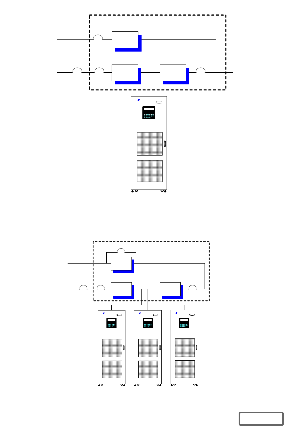
Figure 2 Single Liebert FS unit or multiple Liebert FS units integrated into a UPS system. . . . . . . . . . . . 5
Figure 3 Liebert FS unit(s) integrated into UPS system for ride-through to backup generator. . . . . . . . . . 5
Figure 4 One or more Liebert FS units in parallel with one or more battery strings, battery cabinets
or batteries in racks . . . . . . . . . . . . . . . . . . . . . . . . . . . . . . . . . . . . . . . . . . . . . . . . . . . . . . . . . . . . . . 6
Figure 5 Liebert FS DC power duration for one or multiple units in parallel . . . . . . . . . . . . . . . . . . . . . . . . 8
Figure 6 Integrating a single Liebert FS unit into a UPS system . . . . . . . . . . . . . . . . . . . . . . . . . . . . . . . . . 9
Figure 7 Integrating multiple Liebert FS units into a UPS system . . . . . . . . . . . . . . . . . . . . . . . . . . . . . . . . 9
Figure 8 Liebert FS shipping package . . . . . . . . . . . . . . . . . . . . . . . . . . . . . . . . . . . . . . . . . . . . . . . . . . . . . . 13
Figure 9 Removing lag bolts . . . . . . . . . . . . . . . . . . . . . . . . . . . . . . . . . . . . . . . . . . . . . . . . . . . . . . . . . . . . . . 14
Figure 10 Lifting the Liebert FS cabinet . . . . . . . . . . . . . . . . . . . . . . . . . . . . . . . . . . . . . . . . . . . . . . . . . . . . . 15
Figure 11 Removing the metal support plates . . . . . . . . . . . . . . . . . . . . . . . . . . . . . . . . . . . . . . . . . . . . . . . . . 15
Figure 12 Location of serial and model number plate (cabinet side panel removed and open door) . . . . . . 16
Figure 13 Liebert FS cabinet caster location . . . . . . . . . . . . . . . . . . . . . . . . . . . . . . . . . . . . . . . . . . . . . . . . . . 16
Figure 14 Dimensions, general layout . . . . . . . . . . . . . . . . . . . . . . . . . . . . . . . . . . . . . . . . . . . . . . . . . . . . . . . 17
Figure 15 Internal layout . . . . . . . . . . . . . . . . . . . . . . . . . . . . . . . . . . . . . . . . . . . . . . . . . . . . . . . . . . . . . . . . . 18
Figure 16 Floor mounting . . . . . . . . . . . . . . . . . . . . . . . . . . . . . . . . . . . . . . . . . . . . . . . . . . . . . . . . . . . . . . . . . 19
Figure 17 Floor mounting template layout. . . . . . . . . . . . . . . . . . . . . . . . . . . . . . . . . . . . . . . . . . . . . . . . . . . . 20
Figure 18 Checking hole depth . . . . . . . . . . . . . . . . . . . . . . . . . . . . . . . . . . . . . . . . . . . . . . . . . . . . . . . . . . . . . 21
Figure 19 Inserting anchors . . . . . . . . . . . . . . . . . . . . . . . . . . . . . . . . . . . . . . . . . . . . . . . . . . . . . . . . . . . . . . . 21
Figure 20 Expanding anchors . . . . . . . . . . . . . . . . . . . . . . . . . . . . . . . . . . . . . . . . . . . . . . . . . . . . . . . . . . . . . . 21
Figure 21 Securing mounting brackets to the cabinet . . . . . . . . . . . . . . . . . . . . . . . . . . . . . . . . . . . . . . . . . . . 22
Figure 22 Mounting rear bolts—rear side of cabinet . . . . . . . . . . . . . . . . . . . . . . . . . . . . . . . . . . . . . . . . . . . . 22
Figure 23 Mounting front bolts—front side of cabinet. . . . . . . . . . . . . . . . . . . . . . . . . . . . . . . . . . . . . . . . . . . 23
Figure 24 Bubble level . . . . . . . . . . . . . . . . . . . . . . . . . . . . . . . . . . . . . . . . . . . . . . . . . . . . . . . . . . . . . . . . . . . . 23
Figure 25 Raised floor mounting. . . . . . . . . . . . . . . . . . . . . . . . . . . . . . . . . . . . . . . . . . . . . . . . . . . . . . . . . . . . 25
Figure 26 Liebert FS cabinet with UPS interconnection kit . . . . . . . . . . . . . . . . . . . . . . . . . . . . . . . . . . . . . . 26
Figure 27 Liebert FS with circuit breaker mounting plate and access panels for DC and control
wiring connections . . . . . . . . . . . . . . . . . . . . . . . . . . . . . . . . . . . . . . . . . . . . . . . . . . . . . . . . . . . . . . 27
Figure 28 Typical circuit breaker wiring for DC connections (view from rear of circuit breaker) . . . . . . . . 27
Figure 29 Ground connection on the Liebert FS . . . . . . . . . . . . . . . . . . . . . . . . . . . . . . . . . . . . . . . . . . . . . . . 28
Figure 30 Service panel location . . . . . . . . . . . . . . . . . . . . . . . . . . . . . . . . . . . . . . . . . . . . . . . . . . . . . . . . . . . 29
Figure 31 Auxiliary backup power connections . . . . . . . . . . . . . . . . . . . . . . . . . . . . . . . . . . . . . . . . . . . . . . . . 29
Figure 32 Auxiliary power fused disconnect with connection points for AC wire . . . . . . . . . . . . . . . . . . . . . 30
Figure 33 Top access panel . . . . . . . . . . . . . . . . . . . . . . . . . . . . . . . . . . . . . . . . . . . . . . . . . . . . . . . . . . . . . . . . 30
Figure 34 Remote monitoring (DCM) connections (inside cabinet front door) . . . . . . . . . . . . . . . . . . . . . . . 31
Figure 35 Liebert FS front view . . . . . . . . . . . . . . . . . . . . . . . . . . . . . . . . . . . . . . . . . . . . . . . . . . . . . . . . . . . . 32
Figure 36 Electrical system schematic . . . . . . . . . . . . . . . . . . . . . . . . . . . . . . . . . . . . . . . . . . . . . . . . . . . . . . . 34
Figure 37 Schematic of the levitation system . . . . . . . . . . . . . . . . . . . . . . . . . . . . . . . . . . . . . . . . . . . . . . . . . 37
Figure 38 Liebert FS flywheel module . . . . . . . . . . . . . . . . . . . . . . . . . . . . . . . . . . . . . . . . . . . . . . . . . . . . . . . 38
Figure 39 Rotating group. . . . . . . . . . . . . . . . . . . . . . . . . . . . . . . . . . . . . . . . . . . . . . . . . . . . . . . . . . . . . . . . . . 39
Figure 40 Cross-section of the synchronous reluctance motor rotor . . . . . . . . . . . . . . . . . . . . . . . . . . . . . . . . 39
Figure 41 Vacuum system operation . . . . . . . . . . . . . . . . . . . . . . . . . . . . . . . . . . . . . . . . . . . . . . . . . . . . . . . . 40
Figure 42 Schematic for the speed and temperature sensors . . . . . . . . . . . . . . . . . . . . . . . . . . . . . . . . . . . . . 41
Figure 43 Cutaway flywheel module. . . . . . . . . . . . . . . . . . . . . . . . . . . . . . . . . . . . . . . . . . . . . . . . . . . . . . . . . 42
Figure 44 Voltage and Inductance curve . . . . . . . . . . . . . . . . . . . . . . . . . . . . . . . . . . . . . . . . . . . . . . . . . . . . . 44
Figure 45 Vreg delta help screen . . . . . . . . . . . . . . . . . . . . . . . . . . . . . . . . . . . . . . . . . . . . . . . . . . . . . . . . . . . 45
Figure 46 STANDBY mode diagram. . . . . . . . . . . . . . . . . . . . . . . . . . . . . . . . . . . . . . . . . . . . . . . . . . . . . . . . . 46
Figure 47 Startup mode diagram . . . . . . . . . . . . . . . . . . . . . . . . . . . . . . . . . . . . . . . . . . . . . . . . . . . . . . . . . . . 46
Figure 48 CHARGE mode diagram. . . . . . . . . . . . . . . . . . . . . . . . . . . . . . . . . . . . . . . . . . . . . . . . . . . . . . . . . . 47
Figure 49 READY mode diagram . . . . . . . . . . . . . . . . . . . . . . . . . . . . . . . . . . . . . . . . . . . . . . . . . . . . . . . . . . . 47
Figure 50 DISCHARGE mode diagram . . . . . . . . . . . . . . . . . . . . . . . . . . . . . . . . . . . . . . . . . . . . . . . . . . . . . . 48
Figure 51 SHUTDOWN mode diagram - shutdown after full discharge . . . . . . . . . . . . . . . . . . . . . . . . . . . . 48
Figure 52 SHUTDOWN mode diagram - user-initiated shutdown. . . . . . . . . . . . . . . . . . . . . . . . . . . . . . . . . 49
Figure 53 Typical operation modes . . . . . . . . . . . . . . . . . . . . . . . . . . . . . . . . . . . . . . . . . . . . . . . . . . . . . . . . . . 50
DISCONTINUED
PROD UC T

vii
Figure 54 Control panel view . . . . . . . . . . . . . . . . . . . . . . . . . . . . . . . . . . . . . . . . . . . . . . . . . . . . . . . . . . . . . . 53
Figure 55 Main screen functions. . . . . . . . . . . . . . . . . . . . . . . . . . . . . . . . . . . . . . . . . . . . . . . . . . . . . . . . . . . . 54
Figure 56 Fault screen functions . . . . . . . . . . . . . . . . . . . . . . . . . . . . . . . . . . . . . . . . . . . . . . . . . . . . . . . . . . . 54
Figure 57 Menu tree . . . . . . . . . . . . . . . . . . . . . . . . . . . . . . . . . . . . . . . . . . . . . . . . . . . . . . . . . . . . . . . . . . . . . 58
Figure 58 User level main menu screen . . . . . . . . . . . . . . . . . . . . . . . . . . . . . . . . . . . . . . . . . . . . . . . . . . . . . . 59
Figure 59 READ ONLY level parameter view screen . . . . . . . . . . . . . . . . . . . . . . . . . . . . . . . . . . . . . . . . . . . 60
Figure 60 USER level or above parameter edit screen . . . . . . . . . . . . . . . . . . . . . . . . . . . . . . . . . . . . . . . . . . 60
Figure 61 HELP screen for User Setup Parameters . . . . . . . . . . . . . . . . . . . . . . . . . . . . . . . . . . . . . . . . . . . . 60
Figure 62 Graphical HELP screen for VREG DELTA1, VREG TSOC, and VREG DELTA2 Transition
setup. . . . . . . . . . . . . . . . . . . . . . . . . . . . . . . . . . . . . . . . . . . . . . . . . . . . . . . . . . . . . . . . . . . . . . . . . . 60
Figure 63 USER or higher level parameter selection for view/edit. . . . . . . . . . . . . . . . . . . . . . . . . . . . . . . . . 61
Figure 64 VIEW menu . . . . . . . . . . . . . . . . . . . . . . . . . . . . . . . . . . . . . . . . . . . . . . . . . . . . . . . . . . . . . . . . . . . . 61
Figure 65 TIME/DATE set. . . . . . . . . . . . . . . . . . . . . . . . . . . . . . . . . . . . . . . . . . . . . . . . . . . . . . . . . . . . . . . . . 61
Figure 66 Temperature view . . . . . . . . . . . . . . . . . . . . . . . . . . . . . . . . . . . . . . . . . . . . . . . . . . . . . . . . . . . . . . . 62
Figure 67 Figure 5-14. Voltages view . . . . . . . . . . . . . . . . . . . . . . . . . . . . . . . . . . . . . . . . . . . . . . . . . . . . . . . . 62
Figure 68 History view . . . . . . . . . . . . . . . . . . . . . . . . . . . . . . . . . . . . . . . . . . . . . . . . . . . . . . . . . . . . . . . . . . . 62
Figure 69 Charge history. . . . . . . . . . . . . . . . . . . . . . . . . . . . . . . . . . . . . . . . . . . . . . . . . . . . . . . . . . . . . . . . . . 62
Figure 70 Discharge history . . . . . . . . . . . . . . . . . . . . . . . . . . . . . . . . . . . . . . . . . . . . . . . . . . . . . . . . . . . . . . . 63
Figure 71 Discharge History, Event list screen . . . . . . . . . . . . . . . . . . . . . . . . . . . . . . . . . . . . . . . . . . . . . . . . 63
Figure 72 Warning history, Event list screen . . . . . . . . . . . . . . . . . . . . . . . . . . . . . . . . . . . . . . . . . . . . . . . . . 63
Figure 73 Fault history, Event list screen . . . . . . . . . . . . . . . . . . . . . . . . . . . . . . . . . . . . . . . . . . . . . . . . . . . . 63
Figure 74 Vitals history view . . . . . . . . . . . . . . . . . . . . . . . . . . . . . . . . . . . . . . . . . . . . . . . . . . . . . . . . . . . . . . 64
Figure 75 Counters . . . . . . . . . . . . . . . . . . . . . . . . . . . . . . . . . . . . . . . . . . . . . . . . . . . . . . . . . . . . . . . . . . . . . . 64
Figure 76 Counters - screen 2 . . . . . . . . . . . . . . . . . . . . . . . . . . . . . . . . . . . . . . . . . . . . . . . . . . . . . . . . . . . . . . 64
Figure 77 Options view . . . . . . . . . . . . . . . . . . . . . . . . . . . . . . . . . . . . . . . . . . . . . . . . . . . . . . . . . . . . . . . . . . . 64
Figure 78 Networks view. . . . . . . . . . . . . . . . . . . . . . . . . . . . . . . . . . . . . . . . . . . . . . . . . . . . . . . . . . . . . . . . . . 65
Figure 79 Networks view, Edit DHCP . . . . . . . . . . . . . . . . . . . . . . . . . . . . . . . . . . . . . . . . . . . . . . . . . . . . . . . 65
Figure 80 Networks view, Edit Settings (Service level). . . . . . . . . . . . . . . . . . . . . . . . . . . . . . . . . . . . . . . . . . 65
Figure 81 Electrical view . . . . . . . . . . . . . . . . . . . . . . . . . . . . . . . . . . . . . . . . . . . . . . . . . . . . . . . . . . . . . . . . . . 66
Figure 82 Vitals view . . . . . . . . . . . . . . . . . . . . . . . . . . . . . . . . . . . . . . . . . . . . . . . . . . . . . . . . . . . . . . . . . . . . . 66
Figure 83 Password screens . . . . . . . . . . . . . . . . . . . . . . . . . . . . . . . . . . . . . . . . . . . . . . . . . . . . . . . . . . . . . . . 67
Figure 84 Change password . . . . . . . . . . . . . . . . . . . . . . . . . . . . . . . . . . . . . . . . . . . . . . . . . . . . . . . . . . . . . . . 67
Figure 85 Change password . . . . . . . . . . . . . . . . . . . . . . . . . . . . . . . . . . . . . . . . . . . . . . . . . . . . . . . . . . . . . . . 68
Figure 86 ABOUT screen. . . . . . . . . . . . . . . . . . . . . . . . . . . . . . . . . . . . . . . . . . . . . . . . . . . . . . . . . . . . . . . . . . 68
Figure 87 Serial numbers . . . . . . . . . . . . . . . . . . . . . . . . . . . . . . . . . . . . . . . . . . . . . . . . . . . . . . . . . . . . . . . . . 68
Figure 88 Tools for USER . . . . . . . . . . . . . . . . . . . . . . . . . . . . . . . . . . . . . . . . . . . . . . . . . . . . . . . . . . . . . . . . . 68
Figure 89 USER level menu . . . . . . . . . . . . . . . . . . . . . . . . . . . . . . . . . . . . . . . . . . . . . . . . . . . . . . . . . . . . . . . 78
Figure 90 VIEW menu . . . . . . . . . . . . . . . . . . . . . . . . . . . . . . . . . . . . . . . . . . . . . . . . . . . . . . . . . . . . . . . . . . . . 78
Figure 91 Warning history . . . . . . . . . . . . . . . . . . . . . . . . . . . . . . . . . . . . . . . . . . . . . . . . . . . . . . . . . . . . . . . . 79
Figure 92 Fault history . . . . . . . . . . . . . . . . . . . . . . . . . . . . . . . . . . . . . . . . . . . . . . . . . . . . . . . . . . . . . . . . . . . 79
Figure 93 Warning screen . . . . . . . . . . . . . . . . . . . . . . . . . . . . . . . . . . . . . . . . . . . . . . . . . . . . . . . . . . . . . . . . . 79
Figure 94 Fault screen descriptions . . . . . . . . . . . . . . . . . . . . . . . . . . . . . . . . . . . . . . . . . . . . . . . . . . . . . . . . . 81
Figure 95 Top view of Liebert FS Cabinet with UPS interconnection kit . . . . . . . . . . . . . . . . . . . . . . . . . . . 85
Figure 96 Circuit breaker . . . . . . . . . . . . . . . . . . . . . . . . . . . . . . . . . . . . . . . . . . . . . . . . . . . . . . . . . . . . . . . . . 86
Figure 97 Liebert Series 610 225kVA UPS . . . . . . . . . . . . . . . . . . . . . . . . . . . . . . . . . . . . . . . . . . . . . . . . . . . 87
Figure 98 Liebert Series 610/600T/600 status/control terminal block wiring . . . . . . . . . . . . . . . . . . . . . . . . 88
Figure 99 Liebert FS integrated into a Liebert Npower UPS system. . . . . . . . . . . . . . . . . . . . . . . . . . . . . . . 90
Figure 100 Liebert Series 300 UPS. . . . . . . . . . . . . . . . . . . . . . . . . . . . . . . . . . . . . . . . . . . . . . . . . . . . . . . . . . . 93
Figure 101 Liebert Series 300 status/control terminal block wiring . . . . . . . . . . . . . . . . . . . . . . . . . . . . . . . . 94
Figure 102 Liebert HiPulse status/control terminal block wiring . . . . . . . . . . . . . . . . . . . . . . . . . . . . . . . . . . 96
Figure 103 Circuit-breaker (open door and cabinet faceplate removed). . . . . . . . . . . . . . . . . . . . . . . . . . . . . . 97
Figure 104 Data Collection Module location, features. . . . . . . . . . . . . . . . . . . . . . . . . . . . . . . . . . . . . . . . . . . 100
Figure 105 DCM LAN connection . . . . . . . . . . . . . . . . . . . . . . . . . . . . . . . . . . . . . . . . . . . . . . . . . . . . . . . . . . . 101
Figure 106 Options view . . . . . . . . . . . . . . . . . . . . . . . . . . . . . . . . . . . . . . . . . . . . . . . . . . . . . . . . . . . . . . . . . . 101
Figure 107 Enable or disable DCM . . . . . . . . . . . . . . . . . . . . . . . . . . . . . . . . . . . . . . . . . . . . . . . . . . . . . . . . . . 101
Figure 108 Networks view. . . . . . . . . . . . . . . . . . . . . . . . . . . . . . . . . . . . . . . . . . . . . . . . . . . . . . . . . . . . . . . . . 102
DISCONTINUED
PROD UC T

viii
Figure 109 Networks view, turn off DHCP . . . . . . . . . . . . . . . . . . . . . . . . . . . . . . . . . . . . . . . . . . . . . . . . . . . 102
Figure 110 Networks view, edit settings (service level). . . . . . . . . . . . . . . . . . . . . . . . . . . . . . . . . . . . . . . . . . 102
Figure 111 DCM screen . . . . . . . . . . . . . . . . . . . . . . . . . . . . . . . . . . . . . . . . . . . . . . . . . . . . . . . . . . . . . . . . . . . 103
Figure 112 DCM setup screen . . . . . . . . . . . . . . . . . . . . . . . . . . . . . . . . . . . . . . . . . . . . . . . . . . . . . . . . . . . . . . 103
Figure 113 DCM status screen . . . . . . . . . . . . . . . . . . . . . . . . . . . . . . . . . . . . . . . . . . . . . . . . . . . . . . . . . . . . . 104
Figure 114 Datafiles screen. . . . . . . . . . . . . . . . . . . . . . . . . . . . . . . . . . . . . . . . . . . . . . . . . . . . . . . . . . . . . . . . 105
Figure 115 Data Collection Module reset button . . . . . . . . . . . . . . . . . . . . . . . . . . . . . . . . . . . . . . . . . . . . . . . 106
Figure 116 VIB components . . . . . . . . . . . . . . . . . . . . . . . . . . . . . . . . . . . . . . . . . . . . . . . . . . . . . . . . . . . . . . . 107
Figure 117 I/O Designations . . . . . . . . . . . . . . . . . . . . . . . . . . . . . . . . . . . . . . . . . . . . . . . . . . . . . . . . . . . . . . . 109
Figure 118 Versatile Interface Board mounted in the Liebert FS . . . . . . . . . . . . . . . . . . . . . . . . . . . . . . . . . 110
Figure 119 VIB screw terminal connections. . . . . . . . . . . . . . . . . . . . . . . . . . . . . . . . . . . . . . . . . . . . . . . . . . . 111
Figure 120 No UVR, circuit breaker to terminal block wiring . . . . . . . . . . . . . . . . . . . . . . . . . . . . . . . . . . . . 114
Figure 121 Electrical connections . . . . . . . . . . . . . . . . . . . . . . . . . . . . . . . . . . . . . . . . . . . . . . . . . . . . . . . . . . . 115
Figure 122 Electrical system block diagram . . . . . . . . . . . . . . . . . . . . . . . . . . . . . . . . . . . . . . . . . . . . . . . . . . 116
Figure 123 24 UVR, circuit breaker to terminal block wiring. . . . . . . . . . . . . . . . . . . . . . . . . . . . . . . . . . . . . 117
Figure 124 48 UVR, circuit breaker to terminal block wiring. . . . . . . . . . . . . . . . . . . . . . . . . . . . . . . . . . . . . 117
Figure 125 Outline drawing, Liebert FS cabinet . . . . . . . . . . . . . . . . . . . . . . . . . . . . . . . . . . . . . . . . . . . . . . . 118
Figure 126 Control wiring, external interconnect diagram—Liebert FS cabinet to Liebert Npower UPS
module . . . . . . . . . . . . . . . . . . . . . . . . . . . . . . . . . . . . . . . . . . . . . . . . . . . . . . . . . . . . . . . . . . . . . . . 119
Figure 127 Control wiring external interconnect—Liebert FS to Liebert Series 300 . . . . . . . . . . . . . . . . . . 119
Figure 128 Control wiring—external interconnect diagram, Liebert FS cabinet to Liebert Series 610
UPS module. . . . . . . . . . . . . . . . . . . . . . . . . . . . . . . . . . . . . . . . . . . . . . . . . . . . . . . . . . . . . . . . . . . 120
Figure 129 Control wiring—external interconnect diagram, Liebert FS cabinet to Liebert Series 610
UPS module. . . . . . . . . . . . . . . . . . . . . . . . . . . . . . . . . . . . . . . . . . . . . . . . . . . . . . . . . . . . . . . . . . . 121
Figure 130 Elevation drawing, Liebert FS cabinet with shipping package . . . . . . . . . . . . . . . . . . . . . . . . . . 122
Figure 131 Elevation drawing—Liebert FS cabinet . . . . . . . . . . . . . . . . . . . . . . . . . . . . . . . . . . . . . . . . . . . . 123
Figure 132 Control wiring diagram, Liebert FS power rack system in parallel for capacity . . . . . . . . . . . . 124
Figure 133 Liebert FS cabinet with optional power terminal block . . . . . . . . . . . . . . . . . . . . . . . . . . . . . . . . 125
Figure 134 Liebert FS cabinet mechanical installation. . . . . . . . . . . . . . . . . . . . . . . . . . . . . . . . . . . . . . . . . . 126
Figure 135 Elevation drawing—Liebert FS cabinet with integrated circuit breaker . . . . . . . . . . . . . . . . . . 127
Figure 136 One-line drawing, three Liebert FS systems in parallel configuration . . . . . . . . . . . . . . . . . . . . 128
Figure 137 Control wiring diagram—Liebert FS cabinet - manually operated circuit breaker . . . . . . . . . . 129
Figure 138 One-line diagram—Liebert FS systems with factory-integrated circuit breakers with
Liebert UPS module . . . . . . . . . . . . . . . . . . . . . . . . . . . . . . . . . . . . . . . . . . . . . . . . . . . . . . . . . . . . 130
Figure 139 One-line diagram—single Liebert FS system with factory-integrated circuit breaker
supplying Liebert UPS module . . . . . . . . . . . . . . . . . . . . . . . . . . . . . . . . . . . . . . . . . . . . . . . . . . . 131
Figure 140 Control wiring diagram—Liebert FS - optional electrically operated circuit breaker
Liebert Npower units . . . . . . . . . . . . . . . . . . . . . . . . . . . . . . . . . . . . . . . . . . . . . . . . . . . . . . . . . . . 132
Figure 141 Two-eight paralleled Liebert FS units with factory-integrated circuit breaker in parallel
with a Liebert UPS . . . . . . . . . . . . . . . . . . . . . . . . . . . . . . . . . . . . . . . . . . . . . . . . . . . . . . . . . . . . . 133
Figure 142 One-line diagram, single Liebert FS and battery with factory-integrated circuit breaker
supplying Liebert UPS—UPS DC terminal point of common connection . . . . . . . . . . . . . . . . . . 134
Figure 143 One-line diagram, single Liebert FS and battery with factory-integrated circuit breaker
supplying Liebert UPS—UPS battery point of common connection . . . . . . . . . . . . . . . . . . . . . . 135
Figure 144 Status/control wiring, multiple units. . . . . . . . . . . . . . . . . . . . . . . . . . . . . . . . . . . . . . . . . . . . . . . 136
Figure 145 Wiring specifications, Liebert FS and Liebert Series 300 . . . . . . . . . . . . . . . . . . . . . . . . . . . . . . 137
Figure 146 Wiring specifications, Liebert FS and Liebert Npower. . . . . . . . . . . . . . . . . . . . . . . . . . . . . . . . . 138
Figure 147 Wiring specifications, Liebert FS and Liebert Series 610 . . . . . . . . . . . . . . . . . . . . . . . . . . . . . . 139
Figure 148 Wiring specifications, Liebert FS and Liebert HiPulse, Liebert NXL or Liebert NX . . . . . . . . . 140
Figure 149 Floor mounting template . . . . . . . . . . . . . . . . . . . . . . . . . . . . . . . . . . . . . . . . . . . . . . . . . . . . . . . . 141
Figure 150 System mounting kit. . . . . . . . . . . . . . . . . . . . . . . . . . . . . . . . . . . . . . . . . . . . . . . . . . . . . . . . . . . . 142
Figure 151 Liebert FS block diagram . . . . . . . . . . . . . . . . . . . . . . . . . . . . . . . . . . . . . . . . . . . . . . . . . . . . . . . . 143
Figure 152 Power line diagram . . . . . . . . . . . . . . . . . . . . . . . . . . . . . . . . . . . . . . . . . . . . . . . . . . . . . . . . . . . . . 144
Figure 153 UPS cable entry—bottom . . . . . . . . . . . . . . . . . . . . . . . . . . . . . . . . . . . . . . . . . . . . . . . . . . . . . . . . 145
Figure 154 UPS cable entry—top . . . . . . . . . . . . . . . . . . . . . . . . . . . . . . . . . . . . . . . . . . . . . . . . . . . . . . . . . . . 146
Figure 155 Raised floor mounting . . . . . . . . . . . . . . . . . . . . . . . . . . . . . . . . . . . . . . . . . . . . . . . . . . . . . . . . . . 147
Figure 156 A single Liebert FS+DC unit operating with a UPS in conjunction with batteries . . . . . . . . . . 151
DISCONTINUED
PROD UC T

ix
Figure 157 Multiple Liebert FS+DC units operating with a UPS in conjunction with batteries . . . . . . . . . 151
Figure 158 Two Liebert FS units operating in a paralleled for capacity (not redundancy) configuration,
with a UPS and without batteries attached to the DC bus . . . . . . . . . . . . . . . . . . . . . . . . . . . . . 152
Figure 159 Multiple Liebert FS units operating with a UPS and without batteries attached
to the DC bus. . . . . . . . . . . . . . . . . . . . . . . . . . . . . . . . . . . . . . . . . . . . . . . . . . . . . . . . . . . . . . . . . . 152
Figure 160 Liebert FS connection . . . . . . . . . . . . . . . . . . . . . . . . . . . . . . . . . . . . . . . . . . . . . . . . . . . . . . . . . . . 153
TABLES
Table 1 System information. . . . . . . . . . . . . . . . . . . . . . . . . . . . . . . . . . . . . . . . . . . . . . . . . . . . . . . . . . . . . . . 3
Table 2 General system specifications . . . . . . . . . . . . . . . . . . . . . . . . . . . . . . . . . . . . . . . . . . . . . . . . . . . . . . 6
Table 3 Tightening torque for ground connection . . . . . . . . . . . . . . . . . . . . . . . . . . . . . . . . . . . . . . . . . . . . 28
Table 4 Control panel keyboard layout (refer to Figure 54). . . . . . . . . . . . . . . . . . . . . . . . . . . . . . . . . . . . 53
Table 5 Operation modes . . . . . . . . . . . . . . . . . . . . . . . . . . . . . . . . . . . . . . . . . . . . . . . . . . . . . . . . . . . . . . . . 55
Table 6 System status indicators . . . . . . . . . . . . . . . . . . . . . . . . . . . . . . . . . . . . . . . . . . . . . . . . . . . . . . . . . 55
Table 7 EEPROM parameter number ranges. . . . . . . . . . . . . . . . . . . . . . . . . . . . . . . . . . . . . . . . . . . . . . . . 57
Table 8 PCMC parameters, read-only and user (Liebert FS software). . . . . . . . . . . . . . . . . . . . . . . . . . . . 57
Table 9 Control parameters. . . . . . . . . . . . . . . . . . . . . . . . . . . . . . . . . . . . . . . . . . . . . . . . . . . . . . . . . . . . . . 70
Table 10 Software versions . . . . . . . . . . . . . . . . . . . . . . . . . . . . . . . . . . . . . . . . . . . . . . . . . . . . . . . . . . . . . . . 70
Table 11 Maintenance schedule . . . . . . . . . . . . . . . . . . . . . . . . . . . . . . . . . . . . . . . . . . . . . . . . . . . . . . . . . . . 75
Table 12 Torque specifications (unless otherwise labeled) . . . . . . . . . . . . . . . . . . . . . . . . . . . . . . . . . . . . . . 76
Table 13 Recommended test equipment and tools . . . . . . . . . . . . . . . . . . . . . . . . . . . . . . . . . . . . . . . . . . . . . 77
Table 14 Projected component life, replacement schedule. . . . . . . . . . . . . . . . . . . . . . . . . . . . . . . . . . . . . . . 77
Table 15 Warnings . . . . . . . . . . . . . . . . . . . . . . . . . . . . . . . . . . . . . . . . . . . . . . . . . . . . . . . . . . . . . . . . . . . . . . 80
Table 16 Faults—causes and responses . . . . . . . . . . . . . . . . . . . . . . . . . . . . . . . . . . . . . . . . . . . . . . . . . . . . . 82
Table 17 Troubleshooting. . . . . . . . . . . . . . . . . . . . . . . . . . . . . . . . . . . . . . . . . . . . . . . . . . . . . . . . . . . . . . . . . 83
Table 18 Key to UPS model interconnection . . . . . . . . . . . . . . . . . . . . . . . . . . . . . . . . . . . . . . . . . . . . . . . . . 84
Table 19 Liebert Series 610/600T/600 model ratings . . . . . . . . . . . . . . . . . . . . . . . . . . . . . . . . . . . . . . . . . . . 87
Table 20 Liebert FS Software Control Parameter settings . . . . . . . . . . . . . . . . . . . . . . . . . . . . . . . . . . . . . . 89
Table 21 Liebert FS Software Control Parameters varying with UPS size . . . . . . . . . . . . . . . . . . . . . . . . . 89
Table 22 Liebert Npower model ratings . . . . . . . . . . . . . . . . . . . . . . . . . . . . . . . . . . . . . . . . . . . . . . . . . . . . . 90
Table 23 Liebert FS Software Control Parameters . . . . . . . . . . . . . . . . . . . . . . . . . . . . . . . . . . . . . . . . . . . . 91
Table 24 Liebert FS Software Control Parameters varying with UPS size . . . . . . . . . . . . . . . . . . . . . . . . . 91
Table 25 List of Liebert Series 300 models ratings . . . . . . . . . . . . . . . . . . . . . . . . . . . . . . . . . . . . . . . . . . . . 93
Table 26 Liebert FS Software Control Parameter settings . . . . . . . . . . . . . . . . . . . . . . . . . . . . . . . . . . . . . . 95
Table 27 Liebert FS Software Control Parameters varying with UPS size . . . . . . . . . . . . . . . . . . . . . . . . . 95
Table 28 Liebert HiPulse model ratings . . . . . . . . . . . . . . . . . . . . . . . . . . . . . . . . . . . . . . . . . . . . . . . . . . . . . 96
Table 29 Liebert FS Software Control Parameter settings . . . . . . . . . . . . . . . . . . . . . . . . . . . . . . . . . . . . . 98
Table 30 Liebert FS Software Control Parameters varying with UPS size . . . . . . . . . . . . . . . . . . . . . . . . . 98
Table 31 Liebert FS Software Control Parameter settings . . . . . . . . . . . . . . . . . . . . . . . . . . . . . . . . . . . . . . 98
Table 32 Liebert FS Software Control Parameters varying with UPS size . . . . . . . . . . . . . . . . . . . . . . . . . 98
Table 33 Troubleshooting. . . . . . . . . . . . . . . . . . . . . . . . . . . . . . . . . . . . . . . . . . . . . . . . . . . . . . . . . . . . . . . . 106
Table 34 VIB I/O functions . . . . . . . . . . . . . . . . . . . . . . . . . . . . . . . . . . . . . . . . . . . . . . . . . . . . . . . . . . . . . . 108
Table 35 Submittal documents accompanying Liebert FS. . . . . . . . . . . . . . . . . . . . . . . . . . . . . . . . . . . . . . 113
Table 36 Technical specifications . . . . . . . . . . . . . . . . . . . . . . . . . . . . . . . . . . . . . . . . . . . . . . . . . . . . . . . . . 148
DISCONTINUED
PROD UC T

xDISCONTINUED
PROD UC T
1
IMPORTANT SAFETY INSTRUCTIONS
SAVE THESE INSTRUCTIONS
This manual contains important instructions that should be followed during installation and mainte-
nance of your Liebert FS.
!WARNING
The installation of the Liebert FS must comply with applicable national, federal, state and
local codes.
ONLY qualified service personnel should perform maintenance on the Liebert FS
system. When performing maintenance with any part of the equipment, service personnel
and test equipment should be standing on rubber mats. The service personnel should wear
insulating shoes for isolation from direct contact with the floor (earth ground).
Never work alone, even if all power is removed from the equipment. A second person should
be standing by to assist and summon help in case an accident should occur.
Under typical operation and with all UPS doors closed, only normal safety precautions are
necessary. The area around the Liebert FS system should be kept free of puddles of water,
excess moisture and debris.
Special safety precautions are required for procedures involving handling, installation and
maintenance of the UPS system. Observe all safety precautions in this manual before
handling, installing or operating the UPS system.
This equipment contains circuits that are energized with high voltage. Only test
equipment designed for troubleshooting and for use with those voltages should be used.
Always check with an AC and DC voltmeter to ensure safety before making contact or using
tools. Even when the power is turned Off, dangerously high electric charges may exist within
the UPS.
!WARNING
Exercise extreme care when handling Liebert FS cabinets to avoid equipment damage or
injury to personnel. Refer to Section 3.0 and Section 4.0 for equipment handling
information and installation procedures.
In case of fire involving electrical equipment, use only carbon dioxide fire extinguishers or
others approved for use in fighting electrical fires.
!WARNING
Extreme caution is required when performing maintenance.
Be constantly aware that the Liebert FS contains high DC as well as AC voltages. With input
power off and the battery disconnected, high voltage at filter capacitors and power circuits
should be discharged within 30 seconds. However, if a power circuit failure has occurred, you
should assume that high voltage may still exist after shutdown. Check with a voltmeter
before making contact.
Check for voltage with both AC and DC voltmeters prior to making contact.
!WARNING
When the Liebert FS is under power, both the operator and any test equipment must be
isolated from direct contact with earth ground and the Liebert FS chassis frame by using
rubber mats.
Some components within the cabinets are not connected to chassis ground. Any contact
between floating circuits and the chassis is a lethal shock hazard. Exercise caution that the
test instrument exterior does not make contact either physically or electrically with earth
ground.
DISCONTINUED
PROD UC T
2
Safety Precautions
Read this manual thoroughly, paying special attention to the sections that apply to you, before work-
ing with the Liebert FS.
Under typical operation and with all cabinet doors closed, only normal safety precautions are neces-
sary. The area around the Liebert FS should be kept free from puddles of water, excess moisture or
debris.
Special safety precautions are required for procedures involving handling, installation and mainte-
nance of the Liebert FS. Observe precautions in 7.0 - Maintenance before as well as during perfor-
mance of any maintenance procedure on the Liebert FS.
This equipment contains circuitry that is energized with high voltage. Only test equipment desig-
nated for troubleshooting should be used. This is particularly true for oscilloscopes. Always check
with an AC and DC voltmeter to ensure safety before making contact or using tools. Even when the
power is turned Off, dangerously high voltage may exist at the capacitor banks.
ONLY qualified service personnel should perform maintenance on the Liebert FS. When performing
maintenance with any part of the equipment under power, service personnel and test equipment
should be standing on rubber mats. The service personnel should wear insulating shoes for isolation
from direct contact with the floor (earth ground).
One person should never work alone. A second person should be standing by to assist and summon
help in case an accident should occur.
!CAUTION
Do not loosen or tamper with vacuum components and fittings.
!CAUTION
This unit contains components sensitive to electrostatic discharge.
!CAUTION
Do not remove plug-in printed circuit cards during operation. Improper removal of a card can
cause severe damage to the unit.
!CAUTION
The 110/230VAC must remain connected at all times to ensure reliable backup power to
Liebert FS auxiliaries.
!CAUTION
Do not use this unit for other than its intended use.
!CAUTION
A qualified electrician must perform all electrical connections.
All wiring size and installation must comply with all applicable local, regional and national
regulations (e.g., National Electric Code for USA).
DISCONTINUED
PROD UC T
General System Information
3
1.0 GENERAL SYSTEM INFORMATION
1.1 General Information
1.1.1 Safety Considerations
Read and follow the instructions in this manual before interacting with the system. This document
contains important information and instructions for your Liebert FS. All procedures defined in the
manual related to unpacking, installing and operating the unit must be followed.
Refer to this manual before contacting Liebert Services for technical assistance.
1.1.2 Requesting Assistance from Liebert
If you require assistance for any reason, contact Liebert Services at 1-800-LIEBERT
(1-800-543-2378). Have the following information available:
!WARNING
Failure to recognize electrical hazards could prove fatal. Failure to abide by instructions
provided herein may void your warranty.
Table 1 System information
Date Purchased
Date Installed
Location
System Model Number
System Serial Number
Interconnected UPS Manufacturer
Interconnected UPS Model
Software Version; Primary *
Software Version; Secondary *
Software Version; Bootloader *
DISCONTINUED
PROD UC T
General System Information
4
1.2 General System Description
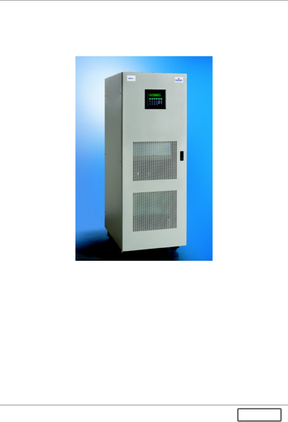
The Liebert FS is a flywheel energy storage system, a mechanical battery that stores energy in the
form of a rotating mass. This energy is immediately convertible to useful electric power.
The Liebert FS is available with a wide performance range up to 200kW as a single unit configura-
tion.
Figure 1 Liebert FS
The Liebert FS is configured as a two-terminal plus ground DC flywheel power system and is used as
a functional replacement for or an availability supplement to a bank of chemical batteries for an
Uninterruptible Power System. Like a chemical battery bank, Liebert FS receives charge and float
power from the two terminal UPS DC bus and returns power to the same DC bus whenever the bus
voltage droops below a programmable threshold level.
Integrated into a UPS, the Liebert FS is used as the alternate source of power to supply DC power to
the UPS inverter if the AC supply voltage (UPS input) is outside the acceptable range. The Liebert FS
supplies power to the UPS inverter until the utility power is restored, until an alternate power source
is available, or until the Liebert FS’ energy is exhausted.
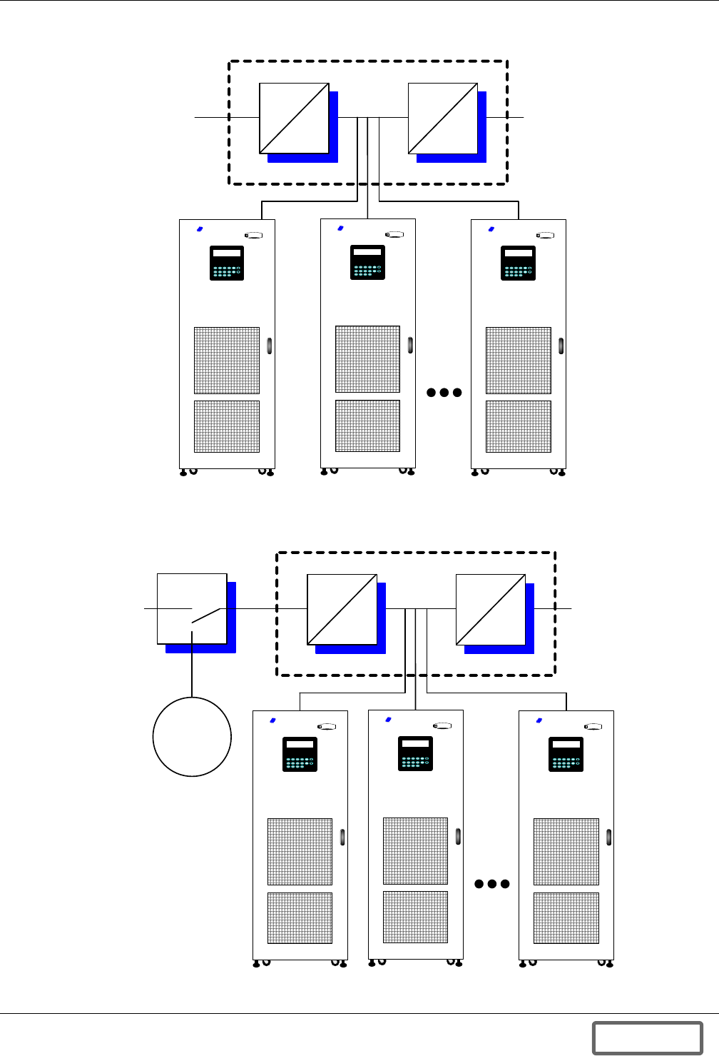
One or more Liebert FS units may be integrated into UPS and can be put in parallel as shown in
Figures 2 and 3, to achieve higher power output or higher ride-through duration.
DISCONTINUED
PROD UC T
General System Information
5
Figure 2 Single Liebert FS unit or multiple Liebert FS units integrated into a UPS system
Figure 3 Liebert FS unit(s) integrated into UPS system for ride-through to backup generator
EMERSO
N
Network Power
Lie ber t
EMERSO
N
N et wor k P ow er
Liebe r t
Loads
UPS Block Diagram
UPS
DC Bus
AC
DC
DC
AC
Liebert FS Unit 2 Liebert FS Unit N
Utility
Power
EMERSO
N
Network Power
Lie ber t
Liebert FS Unit 1
EMERSO
N
N et wor k P ow er
Liebe r t
EMERSO
N
N et wor k P ow er
Liebe r t
EMERSO
N
Net w ork P ower
Liebe r t
Loads
UPS Block Diagram
UPS
DC Bus
AC
DC
DC
AC
Liebert FS Unit 1 Liebert FS Unit 2 Liebert FS Unit N
Utility
Power
ATS
Backup
Generator
DISCONTINUED
PROD UC T
General System Information
6
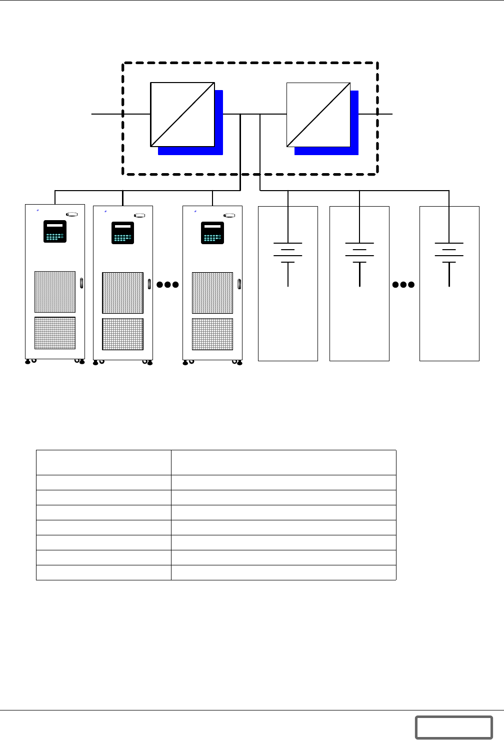
Figure 4 One or more Liebert FS units in parallel with one or more battery strings, battery cabinets or
batteries in racks
1.2.1 General Specifications
Table 2 summarizes the technical specifications of the Liebert FS.
For more-detailed technical specifications, refer to Technical specifications on page 148.
Table 2 General system specifications
Rated Power Delivery Dependent upon the duration required;
refer to Figure 5
Input Voltage (DC) 360 through 600 VDC; > 530 VDC required for 200kW
Output Voltage (DC) 350 through 590 VDC; > 520 VDC required for 200kW
Input Voltage Aux. (AC) 85 VAC – 265 VAC (47-63Hz)
Operating Temperature -20°C to 50°C (-4°F to 122°F)
Non-Operating Temperature -20°C to 80°C (-4°F to 176°F)
Dimensions (W x D x H) 63 x 83 x 180 cm (25 x 33 x 71 in)
Total Weight 590 kg (1,300 lb)
Loads
UPS Block Diagram
UPS
DC Bus
AC
DC
DC
AC
Liebert
FS Unit 1
Liebert
FS Unit 2
Liebert
FS Unit N
Utility
Power
Battery 1
EMERSON
N et wor k P ower
Li eber t
EMERSON
N et wor k P ow er
Li eber t
EMERSON
N et wor k P ow er
Li eber t
Battery 2 Battery N
DISCONTINUED
PROD UC T

General System Information
7
1.2.2 Features and Benefits
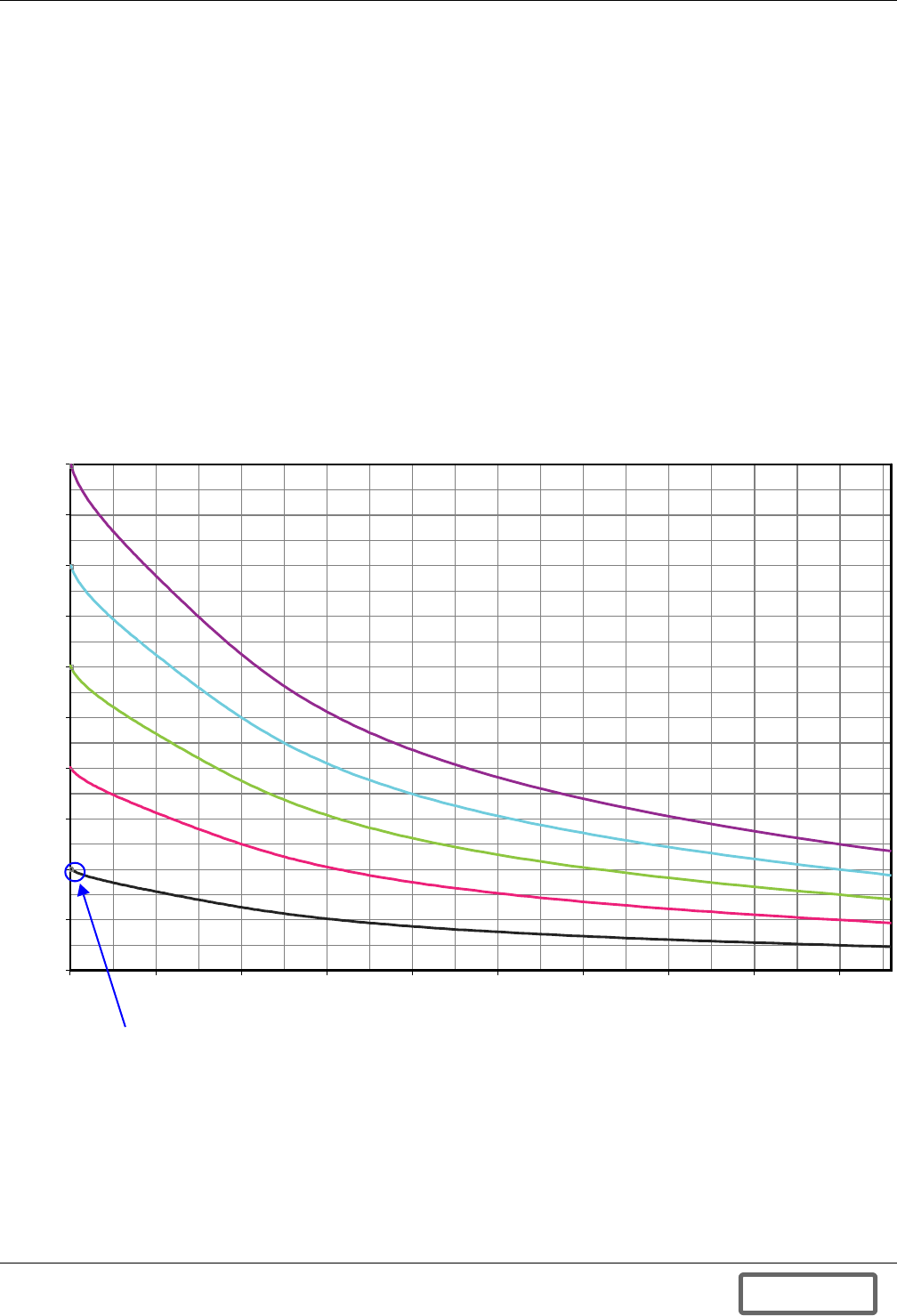
The Liebert FS provides clean constant DC output to the DC bus, at the user-selected, regulated volt-
age, until the stored energy is depleted. See Figure 5 for a graphic representation of the performance
power and duration curves of single and paralleled unit combinations.
Key Technological Features
• Active magnetic bearings
• Internal, integrated vacuum system
• Synchronous reluctance motor-generator
• Fiber composite flywheel
• Unique patented safety system
Key Customer Benefits
• High reliability
• Significantly increased power supply reliability
• Low total cost of ownership
• Operational flexibility
• Environmentally friendly
• Easy to install and easy to operate.
• Low standby losses
• Small footprint
• Lightweight
• Reliable, cost effective power systems for UPS ride-through needs
1.2.3 Applicable Standards and Certification
For distribution in North America, the Liebert FS is listed to the following Underwriter’s Laboratory
(UL) applicable requirements:
• UL 508, Standard for Safety for Electrical Industrial Control Equipment;
• UL 1004, Standard for Safety for Electric Motors;
• UL 1248, Standard for Safety for Engine-Generator Assemblies;
The Liebert FS is designed in accordance with the applicable sections of the requirements published by:
• National Fire Protection Association (NFPA)/National Electric Code (NEC)
• National Electrical Manufacturer's Association (NEMA)
• Occupational Safety & Health Administration (OSHA)
The Liebert FS is also listed to the following Canadian Standards as determined by UL (cUL):
• CSA-C22.2 No. 100-04, “Motors and Generators,”
• CSA-C22.2 No. 14-95, “Industrial Control Equipment,”
The "Uniform Building Code (UBC) Zone 4" certification requirements.
DISCONTINUED
PROD UC T
General System Information
8
For distribution in Europe, the Liebert FS is CE-marked and meets the applicable requirements of
the following European directives:
“Low Voltage Directive” 73/23/EEC and its amendments by the directive 93/68/EEC;
“Machinery Directive” 98/037/EEC and its amendments by the directive 98/79/EEC;
• IEC/EN 60439-1:1999—“Low-voltage switchgear and control gear assemblies Part 1: Type-
tested and partially type-tested assemblies”
• IEC/EN 60204-1:1997—“Safety of machinery - Electrical equipment of machines Part 1: Gen-
eral requirements”
• EN 1127-1:1997—“Explosive atmospheres: Explosion prevention and protection Part 1: Basic
concepts and methodology”
• Machinery Directive Annex 1—“Essential Health and Safety Requirements Relating to the
Design and Construction of Machinery and Safety Components”
“Electromagnetic Compatibility (EMC) Directive” 89/336/EEC and its amendments by the direc-
tives 92/31/EEC and 93/68/EEC.
Figure 5 Liebert FS DC power duration for one or multiple units in parallel
The Liebert FS is integrated into UPS systems as shown in Figures 2 through 4 and Figures 6
and 7.
Output Power vs. Ride-Through Time
(Vbus=540V, Vreg=520V)
DC Output Power (kWb)
1000
900
800
700
600
500
400
300
200
100
0
12 17 22 27 32 37 42 47 52 57
1 Unit
2 Units
3 Units
4 Units
5 Units
Ride-Through Time, Seconds
2400 kW-sec delivered
GTX model, 520 VDC, with filter
12 seconds at 200kW (max. power)
@ 520 VDC min
kWb = Refers to Kilowatts on the DC bus of the UPS system
Discharge Voltage = 520VDC
DISCONTINUED
PROD UC T
General System Information
9
Figure 6 Integrating a single Liebert FS unit into a UPS system
Several Liebert FS units can be put in parallel to achieve higher power output and higher ride-
through duration (see Figure 7). One or more Liebert FS units may also be connected in parallel with
a UPS battery plant (valve- regulated or wet cells) to provide an overall incremental reliability and
life improvement for the DC battery plant. In this situation, the Liebert FS unit would be connected
in parallel with the battery plant (through its own disconnect device) to the UPS DC Bus.
Figure 7 Integrating multiple Liebert FS units into a UPS system
EMERSON
Net w ork Pow er
Lie ber t
CRITICAL
AC LOADS
UPS
Output
Breaker
UPS
DC
Bus
Liebert FS
Static
Switch
UPS
Rectifier
UPS
Input
Breaker
Feeder
Breaker
Bypass
Utility
GRID
Bypass
Breaker
UPS Block Diagram
EMERSON
Net w or k Pow er
Lie ber t
EMERSON
Net w or k Pow er
Lie ber t
EMERSON
Net w ork Pow er
Liebe r t
Liebert FS
Unit #1
Liebert FS
Unit #2
Liebert FS
Unit #N
UPS
Output
Breaker
UPS
Input
Breaker
Feeder
Breaker
Bypass
Utility
GRID
CRITICAL
AC LOADS
UPS
DC Bus
Static
Switch
UPS Block Diagram
UPS
Inverter
UPS
Rectifier
Bypass Breaker
DISCONTINUED
PROD UC T

Site Preparation
10
2.0 SITE PREPARATION
Site preparation for the Liebert FS is minimal. If a UPS system is already installed, the only require-
ments are to properly:
• Place the unit in relation to walls, ceiling and other equipment and
• Fasten the unit to the floor.
2.1 System Location
Choose a location for the Liebert FS that offers:
• Easy connection to inputs, outputs and auxiliary equipment
• Enough space to service the Liebert FS
• Air circulation sufficient to expel heat produced by Liebert FS
• Protection against moisture and excessive humidity (not to exceed 95% non-condensing)
• Protection against excessive dust and other particulate matter
• Compliance with fire prevention regulations and practices
• Operating environment temperature of -4°F to 122°F (-20°C to 50°C)
2.2 Environmental Considerations
Place the system in a clean, dust-free environment. Air must be free to circulate around the cabi-
net(s). The system pulls air through the front of the Liebert FS and exhausts it out the top for cooling.
If the unit must be located in a dusty environment, Liebert recommends installing an optional air fil-
ter, which mounts on the lower inside of the Liebert FS door.
Adequate ventilation, including air conditioning if necessary, must be provided to limit heat accumu-
lation. The ambient temperature for the unit must be from -4°F to 122°F (-20°C to 50°C). Avoid plac-
ing the unit in direct sunlight or near other heat sources.
There is a 32°F (0°C) minimum ambient temperature requirement for starting up the unit. Once the
unit has been running for some time, it will keep itself warm enough in ambient temperatures as low as
-4°F (-20°C).
Humidity is not to exceed 95% (non-condensing).
!CAUTION
The following sections should be read thoroughly before proceeding with site preparation for
installing the Liebert FS.
NOTE
All drawings referred to in this section are in Appendix D.0 - Installation Drawings.
DISCONTINUED
PROD UC T
Site Preparation
11
2.3 Flooring Requirements
2.3.1 Floor Loading
The Liebert FS should be mounted on a finished surface, such as concrete, block, brick or wood. The
floor must be strong enough to support the equipment load and suitable for installation of an anchor-
ing kit with vertical floor loading properly calculated (assume 2,000 PSI or 140 kg/cm2 contact load at
caster wheels; this includes safety factors).
• When installing on a concrete, masonry or stone floor, use the factory-supplied masonry fasteners
(anchors). The fastener manufacturer’s allowable shear load (parallel to floor) for these fasteners
is 2,030 lb. (9 kN) when mounted in normal-weight concrete (2,000 to 3,000 PSI; 140-210 kg/cm2)
of at least 3 in. (7.6cm) thickness.
• If installing on a floor consisting of a material other than normal-weight concrete as described
above, the mounting should be capable of sustaining a shear load (parallel to floor) of at least
1,500 lb. (6.7 kN) for each of the four mounting points.
• If installing on a raised floor that is less than 2 in. (5cm) thick or constructed of a material not
appropriate for the masonry fasteners provided or lag screw engagement, mount using through
bolts with nuts and large diameter washers as shown in Figure 155.
Full details for mounting the cabinet are found in 4.1 - Cabinet Floor Mounting.
2.3.2 Floor-Space Occupation
The Liebert FS cabinet requires a floor space of 23" wide by 33" deep (63 x 83cm), resulting in a foot-
print of 5.7 square feet (0.5m2).
2.3.3 Clearances
The Liebert FS installation requires a ceiling height of at least 7 ft. (214cm).
The unit occasionally vents air out of the top. Loose ceiling tiles above the unit may be moved by the
airflow. Ample clearance to access the cable connection at the top of the unit must also be provided.
All system electrical connections are to be routed through the top or side of the cabinet.
A 36" (91cm) clearance is required in the front of the unit for National Electrical Code (NEC) compli-
ance.
Maintenance access to all components is from the front; no side or back access is required for mainte-
nance. Either side of the system cabinet can be placed against walls (assuming minimum distance
from edge of floor). Repair may require access to the rear of the unit. In this unlikely instance, the
unit may need to be rolled out from its installed location (cabinet is on casters).
2.4 Electrical Considerations
2.4.1 DC Power Connections
Place the Liebert FS as close as practical to the interconnected UPS. The maximum distance allowed
between the UPS and the Liebert FS depends on power levels and the type of DC cables used. Liebert
requires sizing DC cables and placing the Liebert FS for a maximum of no more than 2V loop drop (at
rated power) between the UPS and the Liebert FS.
The Liebert FS is delivered with the standard UPS interconnection kit for connection of the positive
and negative terminals coming from the UPS DC bus or from an external disconnect switch.
For details, see 4.2.2 - DC Power Connections.
NOTE
The above loads (both the fastener manufacturer load and the minimum mounting load)
include the required safety factors.
!CAUTION
A qualified electrician must perform all electrical connections. The wires (DC power,
grounding, optional status/control and auxiliary power supply) that connect the Liebert FS
system(s) to the UPS system must be provided by the electrical contractor (standard) or by
Liebert as an option. Wire size and installation must comply with all applicable local, regional
and national regulations (e.g., National Electric Code for USA).
DISCONTINUED
PROD UC T

Site Preparation
12
2.4.2 Status/Control Connections
Site preparation for Status/Control connections vary according to the type of UPS interconnection kit
provided with your Liebert FS.
Liebert recommends making Status/Control connections on the UPS system side.
For details, refer to 4.2.3 - Status/Control Connections.
2.4.3 Grounding Connections
A grounding wire must be connected from the Liebert FS to the UPS ground terminal. Identify in
advance the location of the grounding terminal on the UPS system. For further details, see 4.2.2 - DC
Power Connections.
2.4.4 AC Power Connections
Plan for the availability of a dedicated 110 or 230VAC, 50 or 60Hz circuit with branch circuit protec-
tion as a source for AC auxiliary power supply to the Liebert FS. This AC power must be rated for
500VA and must be located either on the output circuit of the UPS system or on another UPS-pro-
tected circuit. A qualified electrical contractor should make arrangements for this connection to be
permanent.
The field-supplied AC wire must comply with all applicable local, regional and national regulations
(e.g., National Electric Code for USA). An 18 AWG (0.82mm2) cable is recommended for this connec-
tion.
For details, see 4.2.5 - AC Auxiliary Control Power Supply Connections and Appendix F.0 -
Auxiliary Backup AC Power Supply.
2.4.5 Remote Monitoring Connections—Optional
If the optional Data Collection Module (DCM) is provided with your Liebert FS system, plan to have
communication cables (local network connection, phone line) installed to support the remote notifica-
tion and/or monitoring options chosen.
For details, see 4.2.6 - Remote Monitoring Connections—Optional.
DISCONTINUED
PROD UC T
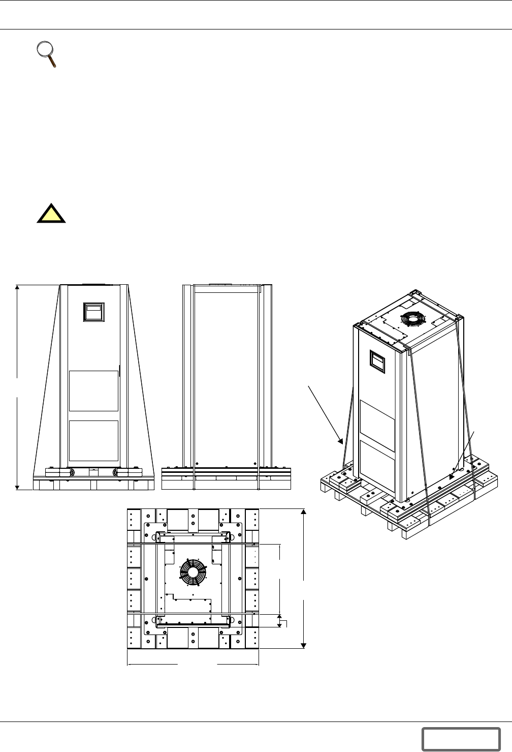
Unloading and Unpacking
13
3.0 UNLOADING AND UNPACKING
3.1 Inspection Before Removal From the Truck
While the Liebert FS shipping package is still on the truck:
• Inspect the equipment and shipping container(s) for any signs of damage or mishandling. Check
also if the shock and tilt gauges (installed for shipping purposes) indicate excessive shock and/or
tilting. If any damage is noted, file a damage claim with the shipping agency within 24 hours and
contact your local sales representative or Liebert at 1-800-LIEBERT to notify them of the damage
claim and the condition of the equipment.
• Compare the contents of the shipment with the bill of lading. Report any missing items to the car-
rier, your local Liebert representative and Liebert at 1-800-LIEBERT immediately. Please have
the bill of lading available.
3.2 Unloading
Figure 8 Liebert FS shipping package
The FS as shipped (see Figure 8) can weigh up to 1,462 lb. (663kg). It must be handled with care. It
must be kept upright—pay special attention to the arrows, which indicate the upright position.
NOTE
All drawings referred to in this section are in Appendix D.0 - Installation Drawings.
!CAUTION
Do not attempt to install the system if damage is apparent.
76"
(1933mm)
Front View
Side View
Shipping Support
Bands
(on either side)
Metal
Support
Plates
(one on
either side)
Shipping Weight:1462 lb. (663kg)
Weight, unit only: 1300 lb (590kg)
24"
(610mm)
48"
(1219mm)
Top View
4.4"
(112mm)
45"
(1143mm)
Do not tilt the Liebert FS
more than 15 degrees
from vertical.
14623
DISCONTINUED
PROD UC T
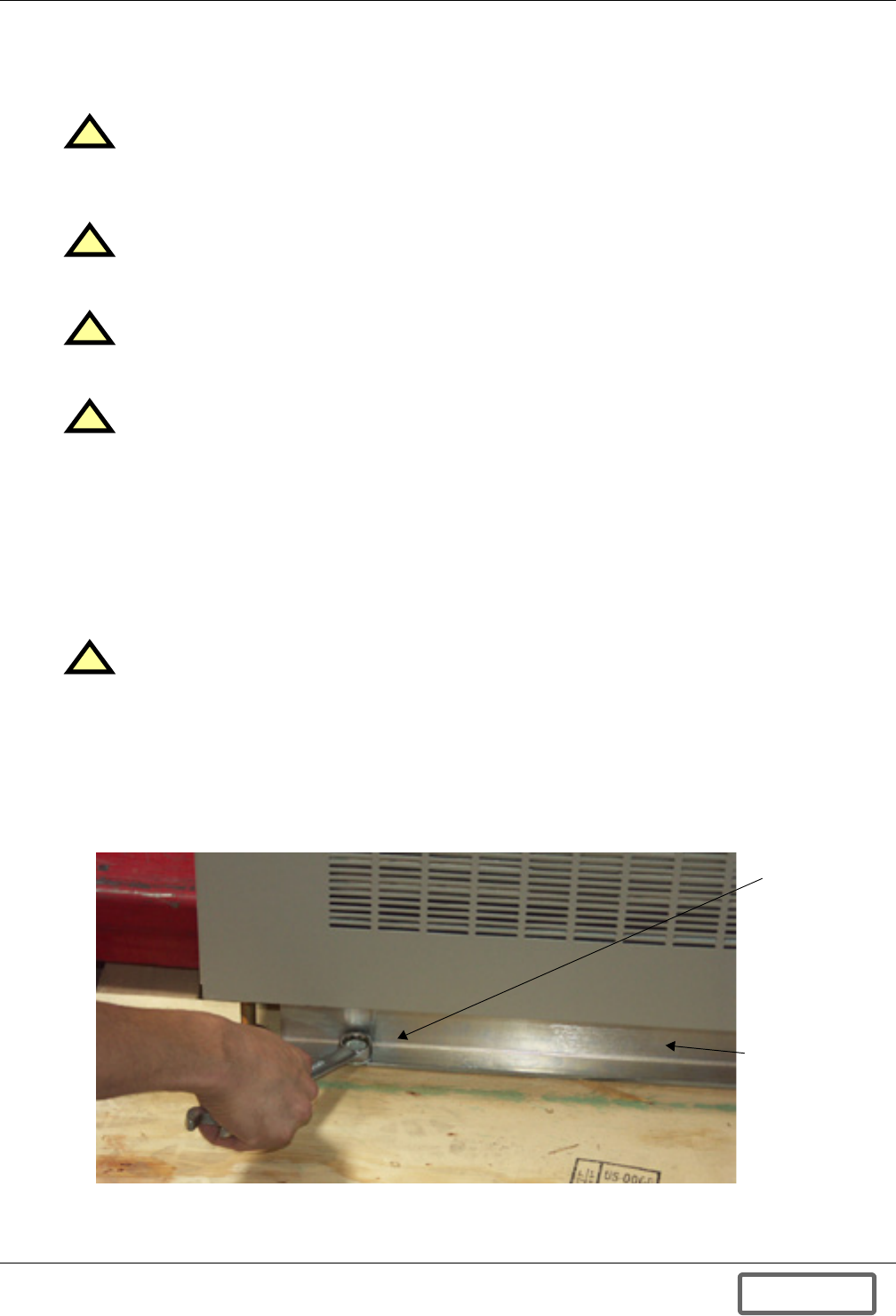
Unloading and Unpacking
14
3.2.1 Handling
The Liebert FS shipping package is designed to be handled using a forklift. Forklift operators must
avoid rough handling when picking up, moving and lowering it.
3.2.2 Unpacking
To reduce the possibility of shipping damage, flywheel cabinets are secured to the pallet by two
mounting brackets and two banding straps. These same two mounting brackets are used to mount the
cabinet to the floor.
Packing elements should be removed in this order to ease unpacking:
1. Cut and remove the banding straps (see Figure 8).
2. Remove hex head bolts holding mounting brackets to pallet as shown in Figure 9.
3. Remove lag bolts holding metal mounting brackets to pallet.
4. Remove mounting brackets from Liebert FS.
Figure 9 Removing lag bolts
!CAUTION
Exhibit care when handling Liebert FS cabinet to avoid equipment damage or injury to
personnel. Failure to do so could throw off the calibration of the mechanical components
contained in the unit and possibly cause permanent damage.
!CAUTION
The Liebert FS has sensitive electronics and mechanical components that have been
calibrated prior to shipment.
!CAUTION
Test lift and balance the cabinet before transporting it. Maintain minimum tilt from vertical
at all times—do not exceed 15 degrees of tilt.
!CAUTION
Sheet metal components and framework may have sharp edges.
!CAUTION
Use care when removing banding straps and metal mounting brackets. The banding straps
are under tension and may snap violently, causing injury. Always wear proper eye and foot
protection when unpacking or installing the system.
Lag bolts
securing
Liebert FS to
shipping pallet
Metal mounting
bracket bolted to
shipping pallet
DISCONTINUED
PROD UC T
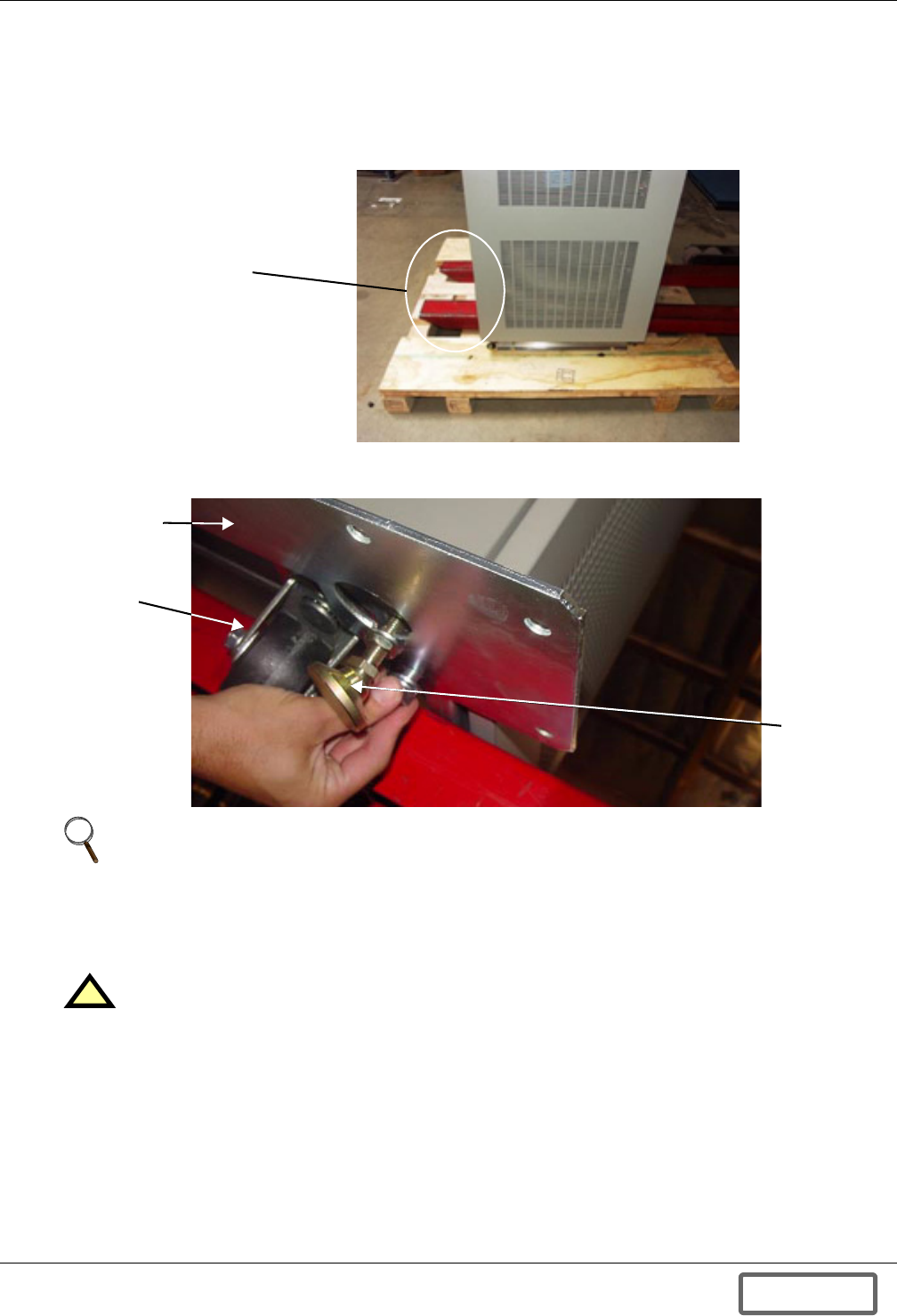
Unloading and Unpacking
15
5. Use a forklift to remove the cabinet from the shipping pallet.
To lift the Liebert FS, the forks should be inserted between the caster wheel assemblies (see
Figure 10). Forks must be extended to the full depth of the cabinet—at least 6 ft. (2m) fork
length—to properly support the equipment (see Figure 10). This likely requires fork extenders.
The Liebert FS unit can weigh up to 1,300 lb. (590kg) and must be handled with care.
Figure 10 Lifting the Liebert FS cabinet
6. Unbolt and remove the two metal support plates (one on either side of the pallet).
Figure 11 Removing the metal support plates
7. Examine the Liebert FS internally and externally for transit damage. Report any damage to the
shipper, your local Liebert representative and Liebert immediately.
8. Check visually for loose connections and unsecured components in the cabinet.
9. You will find the installation manual, operation manual and options manual (if any) enclosed in
the pocket inside the cabinet door (see Figure 12).
10. You will find the serial number and model number plate mounted on the cabinet door pocket or on
the upper right corner of the face of the cabinet frame inside the door (see Figure 12). Record the
model number and serial number in Table 1 - System information.
NOTE
Retain the four bolts (1/2" diameter x 1-3/4" long; 12.7mm diameter x 44.5mm long) attaching
the metal support plates to the cabinet. These will be used to attach brackets to the cabinet for
surface mounting.
!CAUTION
Do not attempt to install the system if there is any damage.
Forks must be
extended the
full depth of the
cabinet
Metal
support
plate
Caster
(for moving
short
distances)
Leveling
foot (one
on each
corner)
DISCONTINUED
PROD UC T
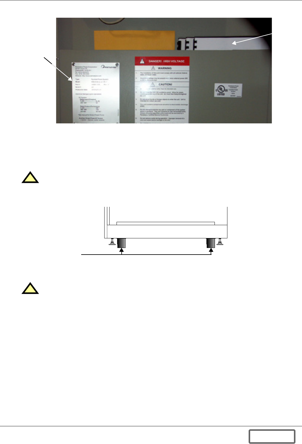
Unloading and Unpacking
16
Figure 12 Location of serial and model number plate (cabinet side panel removed and open door)
3.3 Positioning the Liebert FS
3.3.1 Moving the Liebert FS
When moving the unit a short distance, the Liebert FS may be rolled on its built-in casters (see
Figure 13) to its location.
Figure 13 Liebert FS cabinet caster location
When moving the unit a longer distance or over rough flooring, move the Liebert FS with a forklift or
similar equipment to facilitate the relocation and to reduce vibration of the unit.
3.3.2 Storing the Liebert FS for Delayed Installation
If the equipment will not be installed immediately, it must be stored indoors where the temperature
stays within -4°F to 176°F (-20°C to 80°C) and the humidity is no higher than 95% (non-condensing).
!CAUTION
Before moving the Liebert FS across a floor, determine whether the surface will support the
unit’s weight—1,462 lb. (663kg) as shipped; 1,300 lb. (590kg) uncrated.
!CAUTION
Ensure that the handling equipment is rated for the weight of the Liebert FS—1,462 lb.
(663kg) as shipped; 1,300 lb. (590kg) uncrated.
Serial Number
and Model
Number Plates
Manuals
Casters on each corner
(for moving unit short
distances only)
DISCONTINUED
PROD UC T
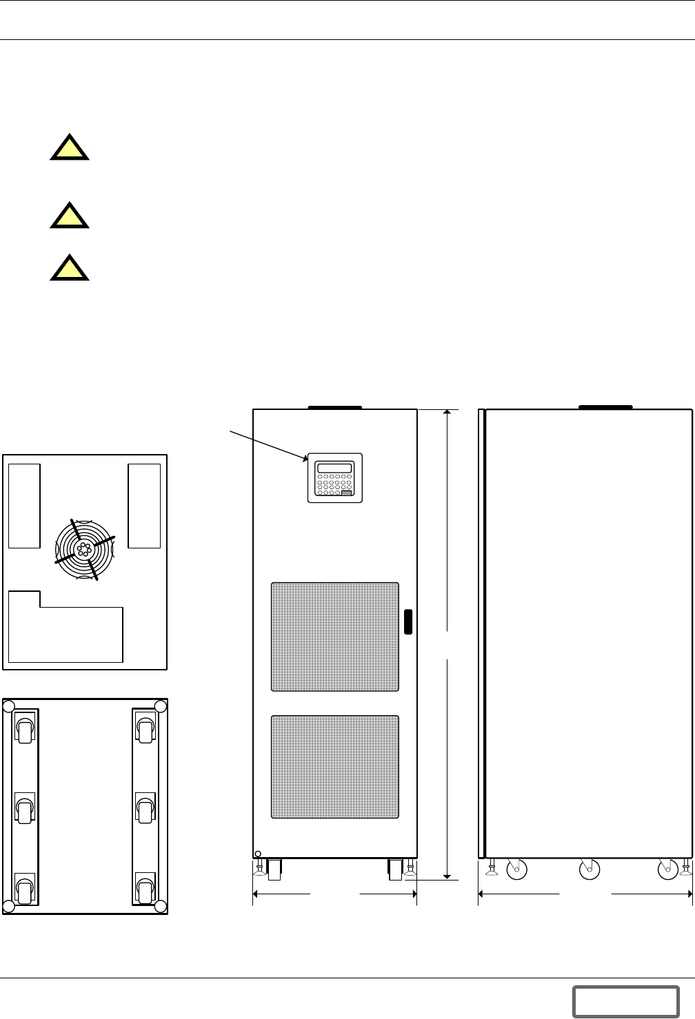
Installation
17
4.0 INSTALLATION
The Liebert FS system design and safety characteristics allow for a relatively simple and quick instal-
lation. The system is designed to be rolled or lifted into place and bolted to the floor using Liebert's
mounting kit, included with the system. The mounting kit in most cases does not require any special
floor preparations (see3.0 - Unloading and Unpacking).
Figure 14 Dimensions, general layout
!CAUTION
The Liebert FS system must be installed in accordance with the instructions and drawings in
this manual.
!CAUTION
Never attempt to install or power up any unit suspected of damage during shipment.
!CAUTION
The Initial System Startup must be performed ONLY under the supervision of a
Liebert-certified service technician to ensure proper system operation. Failure to abide by
instructions provided herein may void your warranty.
Contact your local Liebert sales representative or Liebert at 1-800-LIEBERT to arrange for
system startup.
71-1/8"
(1801mm)
25"
(636mm)
Front
Top
Bottom
32-1/2"
(828mm)
Right Side
Control
Panel
12-100120-09
DISCONTINUED
PROD UC T
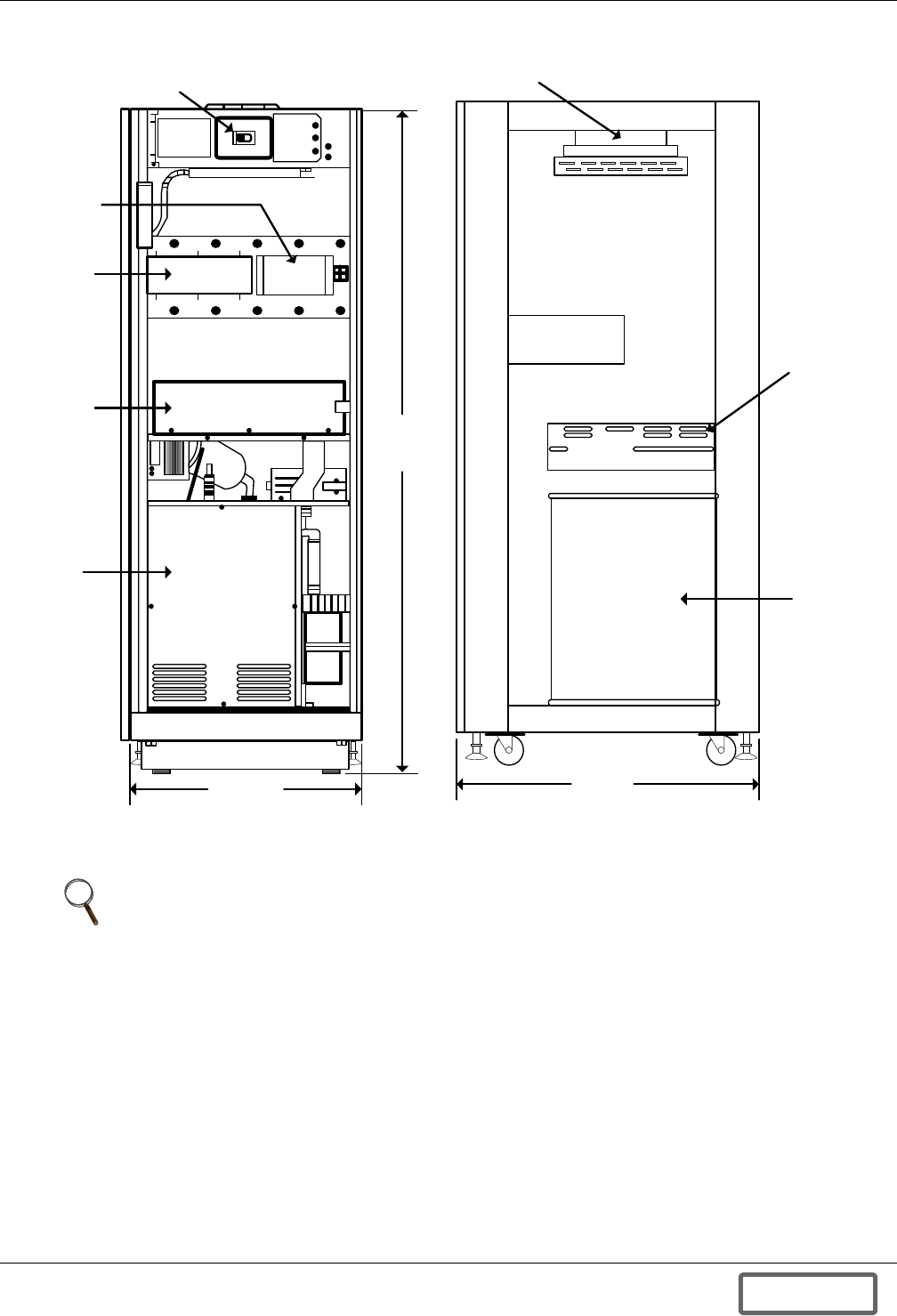
Installation
18
Figure 15 Internal layout
NOTE
The Liebert FS is designed for front-access-only for installation and maintenance. While the
likelihood of repair is minimal, some repair procedures require side and/or rear access.
Normally, the easiest way to handle this is to disconnect the power and control wiring and roll
the unit out into an open area on its casters. While it is acceptable, under certain
circumstances, to connect the Liebert FS to its companion UPS unit through the sides of the
Liebert FS and UPS cabinets rather than through external conduit, repair access to the Liebert
FS unit will be easier to facilitate if through-cabinet wiring is not installed.
32-1/2"
(828mm)
Right Side
(panel removed )
Fan
Magnetic
Levitation
Module
Flywheel
Module
25"
(636mm)
Front
(door open)
71-1/8"
(1807mm)
Factory-Integrated
Circuit Breaker
Data
Control
Module
Versatile
Interface
Board
Inductor
Capacitor
Module
Power
Conversion
Module
DISCONTINUED
PROD UC T
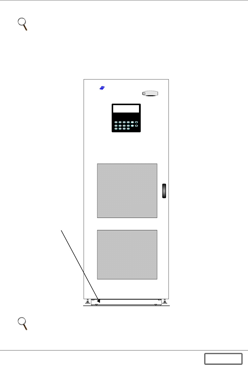
Installation
19
4.1 Cabinet Floor Mounting
• For placement on concrete, masonry or stone floors, see 4.1.1 - Concrete, Masonry or Stone
Floor Mounting.
• For placement on wood floors, see 4.1.2 - Wood Floor Mounting.
• For placement on raised floors, see 4.1.3 - Raised Floor Mounting.
Figure 16 Floor mounting
NOTE
Before beginning, ensure that the floor where the Liebert FS will be mounted meets the floor
loading specifications in 2.3 - Flooring Requirements.
NOTE
All drawings referred to in this section are in Appendix D.0 - Installation Drawings.
EMERSON
Networ k Power
Liebert
Floor Mounting
Bracket
DISCONTINUED
PROD UC T
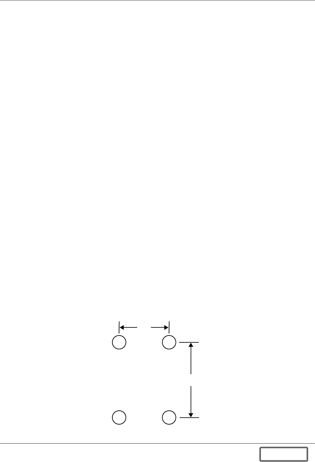
Installation
20
4.1.1 Concrete, Masonry or Stone Floor Mounting
Mounting Kit for Concrete, Masonry or Stone Floors
Liebert has included a complete anchoring kit with each Liebert FS for surface mounting. The kit is
intended to securely fasten the Liebert FS to its intended location for operational safety and seismic
requirements.
This kit includes (items depicted in Figure 150):
• Two (2) cabinet mounting brackets (from shipping pallet)
• Four (4) concrete expansion anchors
• Two (2) drop-in hex head anchor bolts
• Two (2) washers for anchor bolts
• One (1) masonry drill bit
• One (1) floor mounting template (Figure 149)
• Two (2) drop-in hex flange anchor bolts
• One (1) setter rod or drive pin (specifically designed for measuring hole depth and for expanding
the anchors)
• Four (4) hex bolts from shipping package, each 1/2" diameter and 3/4" long (12.7mm diameter x
20mm long)
Mounting Tools
These tools are needed for the mounting the Liebert FS on the floor:
• Concrete drill with 1/2" (12.7mm) minimum chuck size
• Masonry drill bit (included in mounting kit)
• Masonry drill bit—used for pilot hole—for example, 1/8" (3.2mm) diameter
• Setter rod (included in mounting kit)
• Hammer or mallet, 16 oz. (0.5kg) or larger
• Shop vacuum cleaner (to remove dust from hole when drilling)
• 3/4" (19mm) combination wrench
• 18mm combination wrench
Concrete, Masonry or Stone Floor Mounting Instructions
To mount the Liebert FS cabinet on the floor:
1. Prepare a clean, level, finished surface, free of obstructions, for installation of the mounting kit.
2. Tape the floor mounting template mounting template (Figure 149) to the installation location.
3. Using a bit smaller than the one provided in the mounting kit, drill a pilot hole at each of the four
places marked with an “X” on the template.
4. Remove template and continue with larger drill bit provided.
Figure 17 Floor mounting template layout
X X
X X
Drill 4 holes, each
2" (51mm) deep,
with 5/8" masonry bit
29-1/2"
(749mm)
16"
(406mm)
Front of Liebert FS
DISCONTINUED
PROD UC T
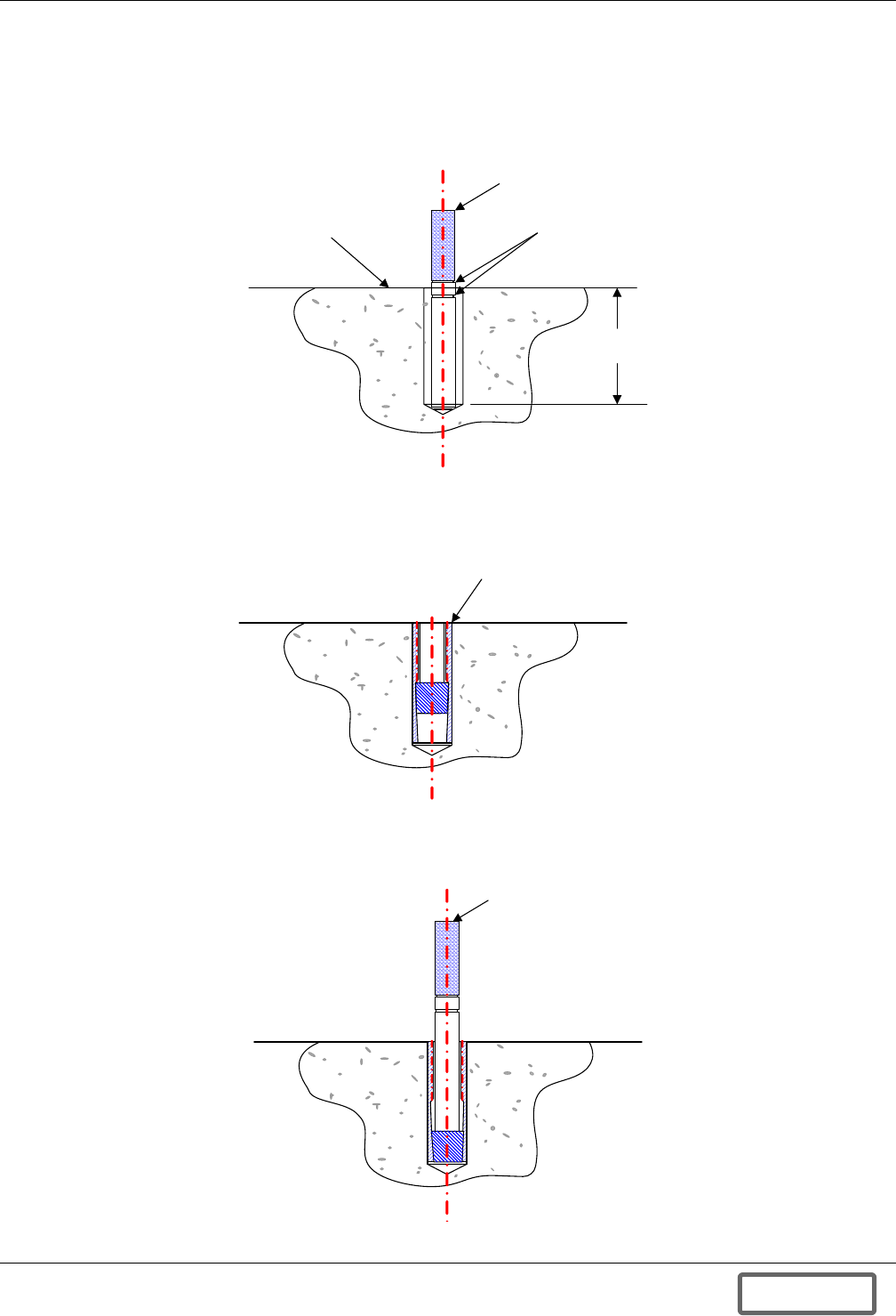
Installation
21
5. Drill 2" (51mm) deep holes in prepared surface using the drill bit included in the kit per bolt
pattern described in Figure 149 - Floor mounting template. The setter rod should be used as a
depth gauge to ensure proper depth. The setter rod is marked with two circles indicating the
maximum and minimum hole depth allowed (see Figure 18).
If a hole is drilled too deep, refill the hole with debris to the achieve proper depth.
Figure 18 Checking hole depth
6. Insert four (4) drop-in concrete expansion anchors into drilled holes.
Figure 19 Inserting anchors
7. Tap anchors into drilled holes using hammer or mallet. When top of anchor is flush with
mounting surface, use setter rod to expand and secure.
Figure 20 Expanding anchors
2.05"
(52mm)
Concrete Floor Depth Marks
Setter Rod (provided)
Insert anchor flush with floor .
Use hammer if required.
Strike with
hammer
to set plug
DISCONTINUED
PROD UC T
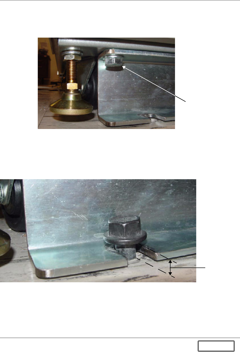
Installation
22
8. Match mounting brackets with the holes on the bottom of the cabinet (see Figure 21). Make sure
that the bracket holes align with the mounting spots on the underside of the cabinet and secure
the brackets with the four (4) 1/2" diameter x 3/4" long (12.7mm diameter x 20mm long) hex bolts
retained from the shipping package. Tighten the bolts with a torque of 40 foot-pounds (54 N-m).
Figure 21 Securing mounting brackets to the cabinet
9. Insert the two (2) hex flange bolts in the rear anchors, where the back of the cabinet will be.
Complete tightening of the rear bolts should result in 1/2" (12.7mm) gap between bolt flange and
floor (see Figure 22 and Figure 134). The rear bolts must be tightened to 20 foot-pounds
(27 N-m) of torque. Bolt height or length may need to be adjusted if mounting surface is uneven or
if mounting bracket does not slide beneath bolt flange.
10. Position and align cabinet and bracket slots with the newly inserted bolts at rear and position
cabinet such that bolts fit in bracket slots (see Figure 22).
Figure 22 Mounting rear bolts—rear side of cabinet
Bolt securing bracket
to cabinet
1/2"
(12.7mm)
floor to
flange
DISCONTINUED
PROD UC T
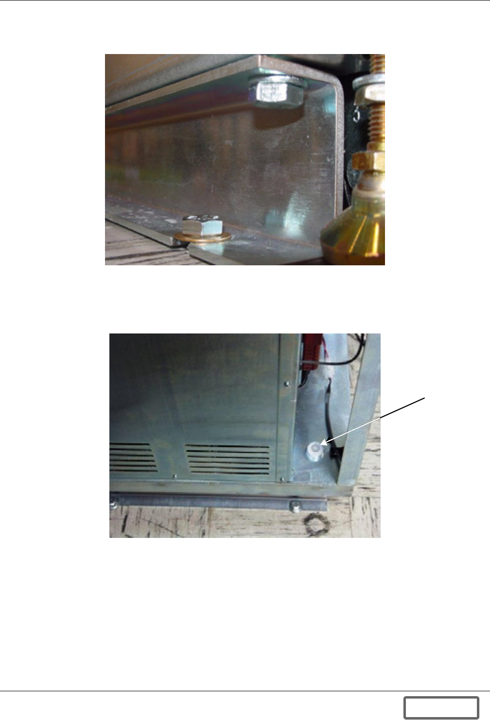
Installation
23
11. Insert and begin tightening two (2) hex head bolts with one washer each through bracket
mounted at front of cabinet into anchor inserts in mounting surface (see Figure 23).
Figure 23 Mounting front bolts—front side of cabinet
12. Check the bubble level on the floor of the cabinet on the right hand side of the Power Conversion
Module (see Figure 24). The Liebert FS is sufficiently level when the bubble is within the outer of
the two circles. If the bubble is outside the outer circle, use the leveling feet to adjust until bubble
is within the outer circle.
Figure 24 Bubble level
13. Once the cabinet is level, firmly tighten the front bolts to drop-in anchors as shown in
Figure 134. The front bolts must be tightened to 40 foot-pounds (54 N-m) of torque.
Bubble
level
DISCONTINUED
PROD UC T
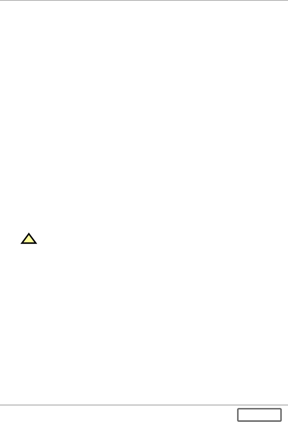
Installation
24
4.1.2 Wood Floor Mounting
Determine which of these cases applies to your installation:
• For wood flooring over concrete, follow the instructions in 4.1.1 - Concrete, Masonry or Stone
Floor Mounting.
• For wood flooring on joists, follow the instructions in this section.
Wood Floor Mounting Parts
• Two (2) cabinet mounting brackets (previously secured Liebert FS cabinet to shipping pallet)
• Four (4) (1/2" diameter x 2-1/2" long) [or 12.7mm diameter x 63.5mm] lag screws (not included in
mounting kit) are recommended
• One floor mounting template, see Figure 149
• Four (4) 1/2" diameter x 3/4" long (12.7mm diameter x 20mm long) hex bolts (from shipping pack-
age—see 3.2.2 - Unpacking)
Wood Floor Mounting Tools
The following tools are needed for the cabinet wood floor mounting:
• Electric drill
• 1/4" (7mm) drill bit
• Drill bit—used for pilot hole—for example, 1/8" (3.2mm) diameter
• Shop vacuum cleaner (to remove dust from hole when drilling)
• 3/4" (19mm) combination wrench
• 18mm combination wrench
Wood Floor Mounting Instructions
Installation in wood floor on joists does not require drop-in anchors.
1. Prepare a clean, level surface, free of obstructions, for installation of the mounting kit.
2. Tape the floor mounting template (Figure 149) to the installation location.
3. Drill pilot holes, remove the template and use a 1/4" (7mm) drill bit to drill holes 2.5" (64mm)
deep.
4. Match mounting brackets with holes under base of cabinet (see Figure 21). Make sure that the
bracket holes align with the mounting spots on the underside of the cabinet and secure brackets
with the four hex bolts retained from the shipping package. Each bolt is 1/2" diameter x 3/4" long
(12.7mm diameter x 20mm long). Tighten the bolts with a torque wrench at 40 foot-pounds
(54 N-m).
5. Insert two lag screws through bracket mounted at rear of cabinet leaving head with 1/2" (12.7mm)
gap above floor (see Figure 22).
6. Position and align cabinet and bracket slots with the newly drilled holes at rear and position
cabinet such that bolts fit in bracket slots (see Figure 22).
7. Insert two (2) lag screws through bracket mounted at front of cabinet (see Figure 23).
8. Check the bubble level on the floor of the cabinet on the right hand side of the Power Conversion
Module (see Figure 24). The Liebert FS is sufficiently level when the bubble is within the outer of
the two circles. If the bubble is outside the outer circle, use the leveling feet to adjust until bubble
is within the outer circle.
9. Once the cabinet is level, firmly tighten the front lag screws to a torque 40 foot-pounds (54 N-m).
!CAUTION
Ensure that holes are centered in the joist.
DISCONTINUED
PROD UC T
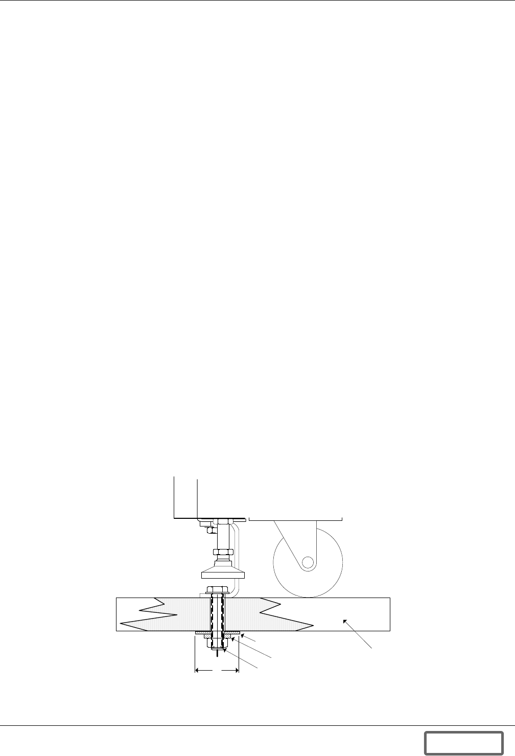
Installation
25
4.1.3 Raised Floor Mounting
Raised Floor Mounting Kit
Liebert has included a complete anchoring kit with each Liebert FS for surface mounting. The kit is
intended to securely fasten the Liebert FS to its location for operational safety and seismic requirements.
The anchoring kit includes:
• One floor mounting template, Figure 149
• 2 cabinet mounting brackets
• 4 drop-in hex flange bolts, each 1/2" diameter, 3" long (12.7mm, 76.mm)
• 4 washers (1/2" hole and 2" outer diameter) for hex flange bolts
• 4 lock washers for hex flange bolts
• 4 nuts for hex flange bolts, each 1/2" (12.7mm)
• 4 hex bolts, each 1/2" diameter, 3/4" long (12.7mm diameter, 20mm long) retained from shipping
package (see 3.2.2 - Unpacking)
Raised Floor Mounting Tools
The following tools are needed for the cabinet raised floor mounting:
• Electric drill with 1/2" (12.7mm) minimum chuck size
• 5/8" (16mm) drill bit
• Drill bit—used for pilot hole—for example, 1/8" (3.2mm) diameter
• 3/4" (19mm) combination wrench
• 18mm combination wrench
Raised Floor Mounting Instructions
To mount the Liebert FS cabinet on the floor:
1. Prepare a clean, level finished surface, free of obstructions, for installation of mounting kit.
2. Tape the floor mounting template (see Figure 149) to installation location, pre-drill a pilot hole,
then remove paper and continue with 5/8" (16mm) drill bit.
3. Match mounting brackets with holes under base of cabinet (see Figure 21). Make sure that the
bracket holes align with the mounting spots on the underside of the cabinet and secure brackets
with the four 1/2" diameter x 3/4" long (12.7mm diameter x 20mm long) hex bolts retained from
the shipping package. The bolts must be tightened to 40 foot-pounds (54 N-m) of torque.
4. Position and align cabinet and bracket slots with the newly drilled holes (see Figure 22).
5. Insert four drop-in hex flange bolts through bracket mounted at front and rear of cabinet (see
Figure 23).
Figure 25 Raised floor mounting
2"
(50mm) dia.
1/2" (12.7mm)
dia. steel bolt
Large diameter washer
Lockwasher Raised
floor
DISCONTINUED
PROD UC T
Installation
26
6. Attach a large diameter washer, a lock washer and a nut to each hex flange bolts as described in
Figure 25 and Figure 155.
7. Check the bubble level on the floor of the cabinet on the right hand side of the Power Conversion
Module (see Figure 24). The Liebert FS is sufficiently level when the bubble is within the outer of
the two circles. If the bubble is outside the outer circle, use the leveling feet to adjust until bubble
is within the outer circle.
8. Once cabinet is level, firmly tighten down all hex flange bolts with nuts. The bolts must be
tightened to 40 foot-pounds (54 N-m) of torque.
4.2 Wiring Connections
4.2.1 General Wiring Considerations
The electrical connections to the Liebert FS are:
• DC power
• Status/control (upgraded)
• Ground
• Auxiliary backup power
• Remote monitoring—optional
Figure 26 Liebert FS cabinet with UPS interconnection kit
Power and Status/Control wiring must be run in separate conduits or cable trays. Refer to Appendix
D.0 - Installation Drawings for locations of the various electrical connections between Liebert FS
system(s) and UPS system.
!CAUTION
A qualified electrical contractor must perform all electrical connections. The wires (DC power,
ground, upgraded status/control and auxiliary power supply) that connect the Liebert FS
system(s) to the UPS system are field-supplied or by Liebert as an option. Wire size and
installation must comply with all applicable local, regional and national regulations (e.g.,
National Electric Code for USA).
!CAUTION
Power and Status/Control wiring must be separated.
DC Power
Terminals
Front Rear
Circuit
Breaker
Status/Control
Terminal Block
(upgraded)
Manufacturer’s
Connection
Fan Coil Module
Ground Terminal
DISCONTINUED
PROD UC T
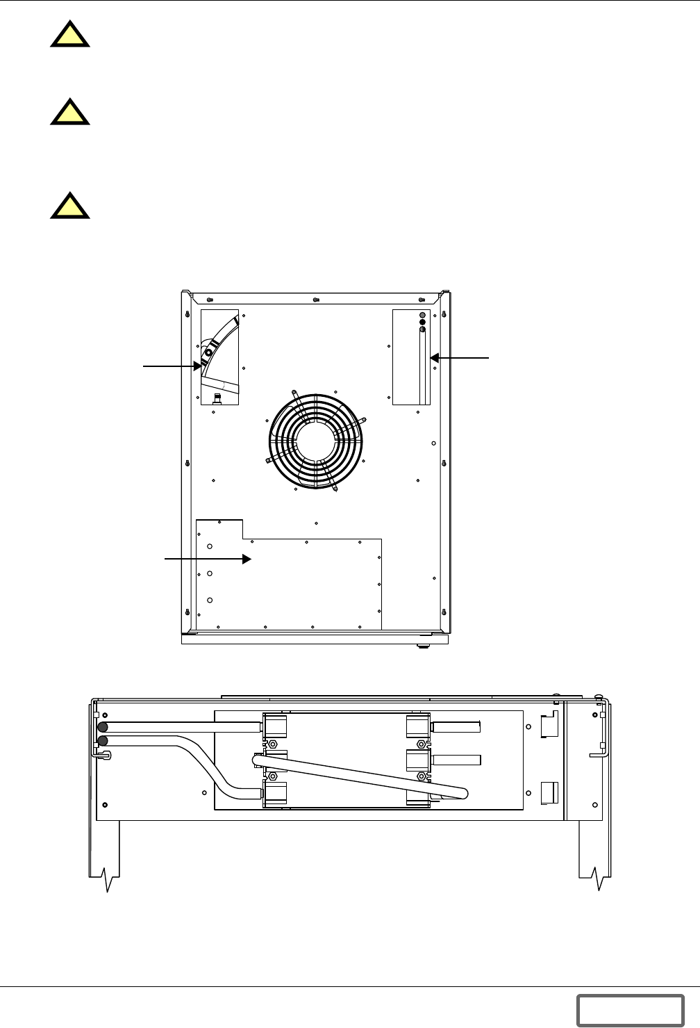
Installation
27
Figure 27 Liebert FS with circuit breaker mounting plate and access panels for DC and control wiring
connections
Figure 28 Typical circuit breaker wiring for DC connections (view from rear of circuit breaker)
!CAUTION
Do not cut entry holes for conduit while the access plates are still set on the top of the
Liebert FS cabinet. Remove the access plates from the cable-access areas in the top of the
Liebert FS cabinet prior to cutting entry holes in them.
!CAUTION
After reinstalling access plates, be certain that no foreign matter (metal shavings, insulation
or wire fragments, etc.) remains inside the Liebert FS. Likewise, be certain to block any
“extra holes” in the plates through which foreign matter (or rodents) could later enter the
Liebert FS.
!CAUTION
The instructions for installation of DC Power AND Status/Control connections vary according
to the type of UPS interconnection kit that is integrated into your Liebert FS unit.
Control and
Communication
Access Panel
Circuit Breaker
Mounting Plate
DC and Ground
Connections
Access Panel
TOP VIEW
POS POS
NEG
NEG
DISCONTINUED
PROD UC T
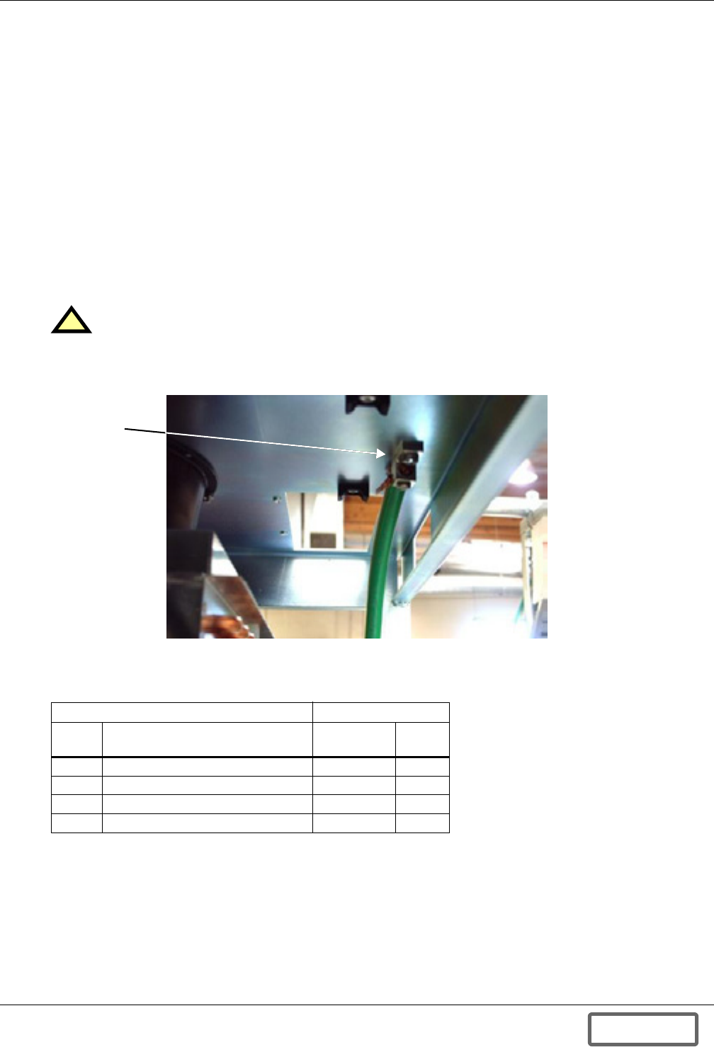
Installation
28
4.2.2 DC Power Connections
The instructions for installation of DC power connections vary according to the type of UPS intercon-
nection kit integrated into your Liebert FS unit. Follow the installation instructions in Appendix
A.0 - UPS Interconnection Kits for the relevant UPS interconnection kit installed in your unit.
4.2.3 Status/Control Connections
The instructions for installing Status/Control connections vary according to the type of UPS intercon-
nection kit that is integrated into your Liebert FS. Follow the installation instructions in Appendix
A.0 - UPS Interconnection Kits for the relevant UPS interconnection kit installed in your unit.
4.2.4 Ground Connections
A ground connection is available on the Liebert FS (see Figure 29). The electrical contractor must
ensure that the Liebert FS is effectively grounded to UPS chassis or UPS ground terminal. The
ground connection must be as short as possible. The maximum ground wire size is 1/0 AWG - 600VDC
wire (54mm2 wire section). Wire size and installation must comply with all applicable local, regional
and national regulations (e.g., National Electric Code for USA). Check all connections with Multi-
meter to verify ground continuity. (Refer also to Appendix E.1 - Ground Test Procedure.
Figure 29 Ground connection on the Liebert FS
The tightening torque for the ground connections must be in accordance with Table 3. Use these val-
ues unless the equipment is labeled with a different torque value.
!CAUTION
Ensure that all grounds are secure and free of corrosion. Proper grounding is necessary for
optimum performance, safety and reliability.
Table 3 Tightening torque for ground connection
Ground Wire Gauge Tightening Torque
AWG
Approximate metric
equivalent wire section (mm2)
Inch-
pounds N-m
4 21 110 12
2 34 150 17
1 42 150 17
1/0 54 180 20
Ground Terminal
Locations (DC
ground and filter
caps if required)
Side panel
removed for
clarity.
DISCONTINUED
PROD UC T
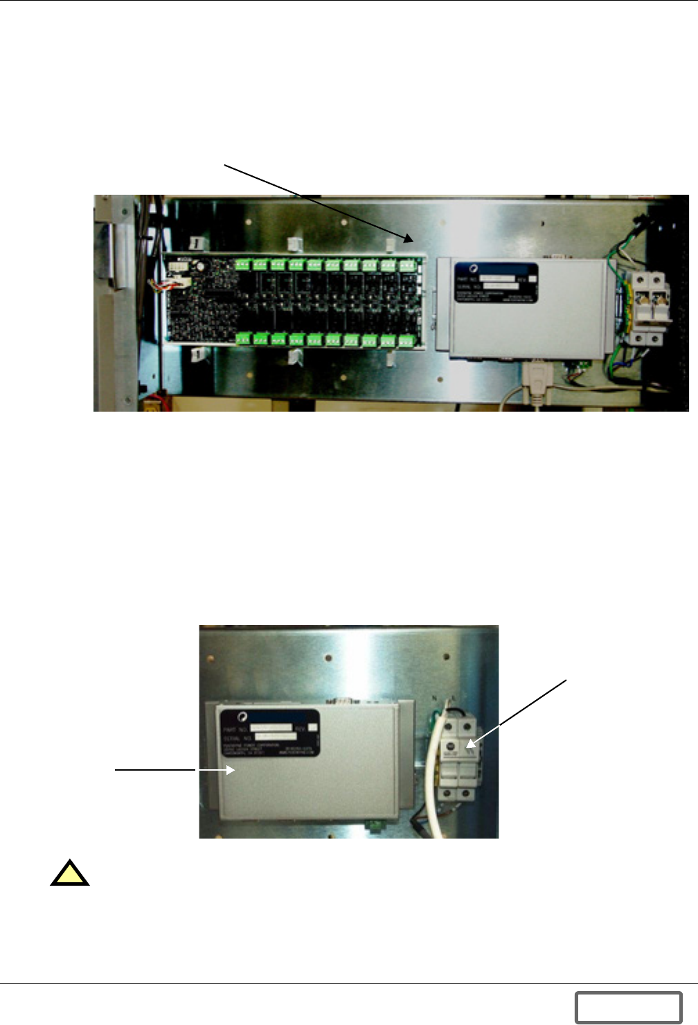
Installation
29
4.2.5 AC Auxiliary Control Power Supply Connections
The AC auxiliary power supply connections to the Liebert FS are made through the auxiliary power
fused disconnect on the mounting plate above the inductor-capacitor module and to the right of the
optional VIB and DCM modules (see Figure 30). See Appendix F.0 - Auxiliary Backup AC
Power Supply for details on the purpose of the auxiliary AC power supply.
Figure 30 Service panel location
The Auxiliary Power Fused Disconnect (see Figure 31) accommodates the connection of an AC wire
(Line, Neutral, Ground) and is rated for 110/230 VAC - 50/60 Hz. Open the circuit while wiring, check
the fuses and then close it. The AC wire must be connected to the auxiliary power fused disconnect
from the top to a dedicated AC circuit rated for 500VA with branch circuit protection. This AC outlet
must be connected to a protected low-voltage (110VAC-230VAC, 500VA) source. A qualified electrical
contractor should make this connection permanent.
The AC wire is field-supplied. It must conform to all applicable local, regional, national regulations,
such as the National Electric Code for USA. An 18 AWG (0.82 mm2) cable is recommended for this
connection.
Tighten the connections for the 18 AWG cable (0.82 mm2) to 15 inch-pounds (1.6N-m).
Figure 31 Auxiliary backup power connections
!CAUTION
The AC power supply must remain connected at all times. Precautions must be taken to
ensure that the connection is not broken. Disconnection may cause damage to the equipment.
Service Panel (cover removed);
Provides access to fused disconnect
and the optional VIB and DCM.
AC Auxiliary
Power Fused
Disconnect
Location of MCM
(cover plate
removed)
DISCONTINUED
PROD UC T
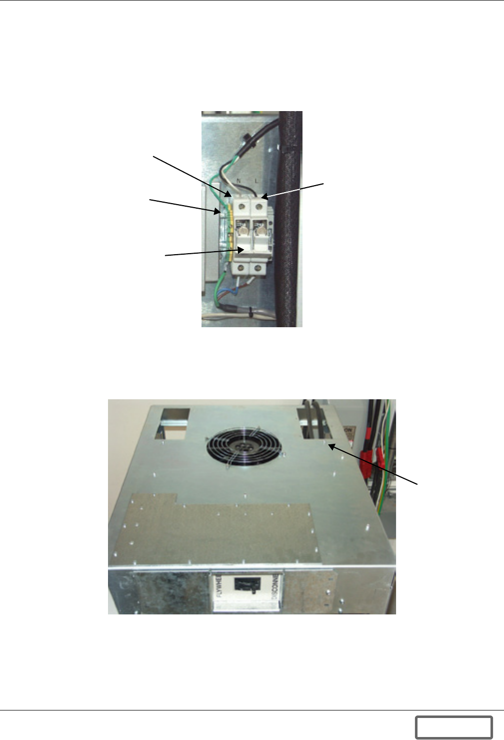
Installation
30
The AC wire is field-supplied. Wire size and installation must comply with all applicable local,
regional and national regulations (e.g., National Electric Code for USA). An 18 AWG cable (approxi-
mate metric equivalent: 0.82mm2 wire section) is recommended for this connection.
Figure 32 shows the auxiliary power fused disconnect and terminals 1, 2 and 3, the landing points
for the AC wire on the Liebert FS side. Open the circuit while wiring, check the fuses and close after-
wards when ready to test or start up Liebert FS.
Figure 32 Auxiliary power fused disconnect with connection points for AC wire
The AC wire should be pulled from the left (top access recommended) and through the rear top access
panel (see Figure 33). Run the AC wire along the underside of the top cabinet frame rail from the
rear to the front of the cabinet. Terminate the AC wire at the fused disconnect (pictured in Figure 32;
see also Figure 26).
Figure 33 Top access panel
Terminal 1
Neutral
Terminal 2
Line
Terminal 3
Ground
Fused disconnect
Top access
panel for
AC auxiliary
power supply
connections
Front of Liebert FS
DISCONTINUED
PROD UC T
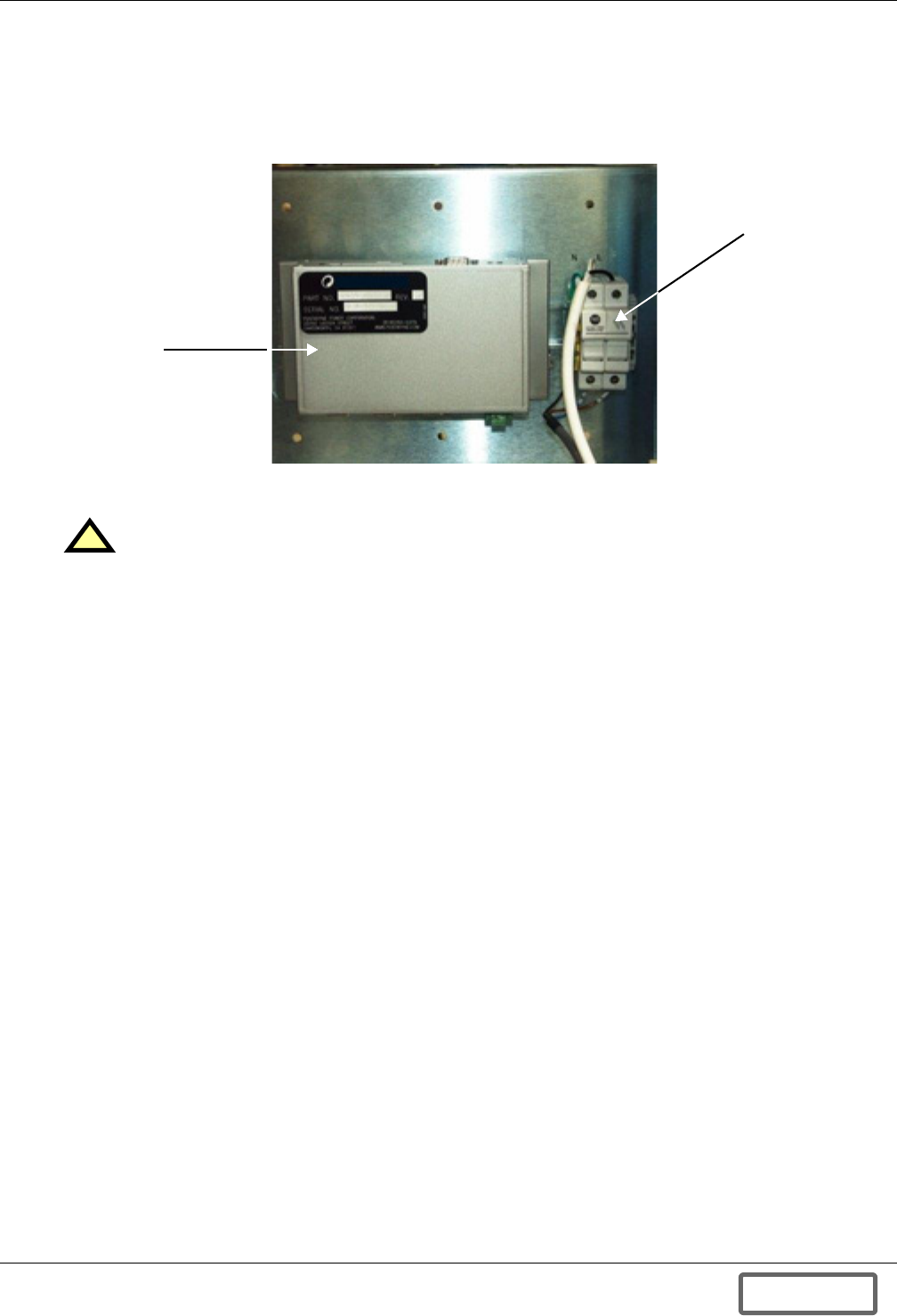
Installation
31
4.2.6 Remote Monitoring Connections—Optional
The Liebert FS standard unit does not include remote monitoring connections. Remote monitoring
capabilities are provided as an option see Figure 34). If your unit is equipped with the optional Data
Collection Module (DCM), refer to the installation and configuration instructions in Appendix B.0 -
Data Collection Module.
Figure 34 Remote monitoring (DCM) connections (inside cabinet front door)
4.3 Startup Considerations
!CAUTION
The Initial System Startup must be performed ONLY under the supervision of a
Liebert-certified service technician to ensure proper system operation. Failure to abide by
instructions provided herein may void your warranty.
Contact your local Liebert representative or call 1-800-LIEBERT to arrange for system
startup.
AC Auxiliary
Power Fused
Disconnect
Location of MCM
(cover plate
removed)
DISCONTINUED
PROD UC T
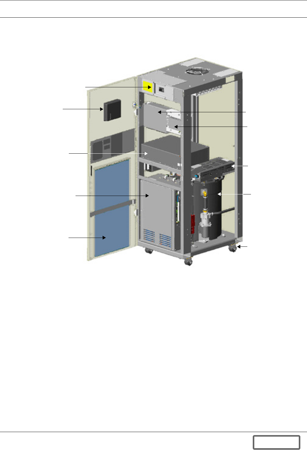
System Overview
32
5.0 SYSTEM OVERVIEW
5.1 Detailed System Description
Figure 35 Liebert FS front view
UPS Interconnection Kit
Power
Conversion
Module
Built-In Casters, 4
Magnetic Levitation
Module (above
flywheel module)
Versatile Interface
Board (option)
LCD
Control
Panel
Motor Generator
Filter Assembly
Data Collection
Module (option)
Flywheel Module)
Air Filter
(optional)
Front View (door open,
right side panel removed)
DISCONTINUED
PROD UC T

System Overview
33
5.1.1 System Module Description
The Liebert FS is a modular system composed as follows:
• Control Panel
• UPS Interconnection Kit
• Power Conversion Module
• Main Control Module
• Flywheel Module
• E-Stop (optional-special order)
Components are illustrated in Figure 35.
Control Panel
The Liebert FS uses a control panel as the primary means for an operator to interface with the sys-
tem.
UPS Interconnection Kit
The UPS Interconnection Kit is a module that enables the physical interconnection of the Liebert FS
and a UPS system. There are several versions that vary, depending on the UPS model.
The Liebert FS is delivered with a UPS interconnection kit consisting of a circuit breaker for connec-
tion of the positive and negative terminals coming from the UPS DC bus or from an external discon-
nect switch.
Power Conversion Module
The power conversion module is a bi-directional power electronics-based power converter capable of
sourcing or sinking power to and from the UPS DC bus.
While performing the Liebert FS’s backup power mission, the power conversion module converts
“variable frequency - variable voltage” AC power from the Liebert FS’ motor-generator and delivers
regulated DC voltage output to the UPS DC bus.
Conversely, for the Liebert FS’s needs in charging power, the power conversion module converts DC
power from the UPS DC bus into “variable frequency - variable voltage” AC power for the Liebert FS’
motor-generator.
Main Control Module
The Main Control Module provides the overall control of the Liebert FS as well as the specific control
for:
• Motor-generator
• Active magnetic levitation hardware
Flywheel Module
The Flywheel Module houses several major components:
• Motor-generator—synchronous reluctance technology
• Rotating group—high-speed carbon composite flywheel, high-speed shaft and rotor of the motor-
generator
• 5-axis active magnetic levitation hardware
• Molecular vacuum pump
E-Stop
The E-Stop is an Emergency Stop that allows the Liebert FS to disconnect from the UPS. The E-Stop
is a CE requirement for systems shipping to Europe (and other areas requiring the CE Mark). The
feature is available elsewhere as an option. Two choices are available for how the E-Stop is powered,
internally or externally. If E-Stop is activated, Liebert FS will enter a self-discharge and shutdown
mode.
DISCONTINUED
PROD UC T
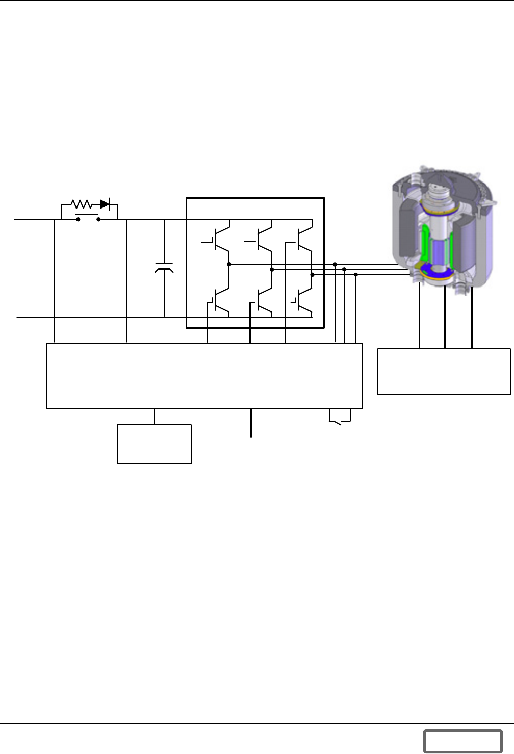
System Overview
34
5.1.2 Power System
The electrical system of the Liebert FS is shown in Figure 36. The schematic shows the Magnetic
Levitation Module [see 5.1.7 - Magnetic Levitation Module (MLM)]. The pre-charge resistor and
contactor which limit the inrush current into the DC bus capacitors. The six-pulse IGBT power con-
verter (IGBT Power Conversion Module (PCM) on page 36) which is controlled by the Power
Conversion Module Controller (Power Conversion Module on page 33) and which also monitors
and controls the operation of the entire system. These components are housed within the Power Con-
version Module. The Flywheel Module is shown as a cross-section to illustrate the rotating group and
the synchronous reluctance motor-generator.
Figure 36 Electrical system schematic
5.1.3 System Performance
The maximum output power of the Liebert FS varies according to the duration required. This is illus-
trated in Figure 5 (output power versus time). Increased power, duration or redundancy may be
achieved by adding units in parallel as shown in Figures 2 through 4.
Magnetic Levitation
Module
Control
Panel
DC Monitoring Motor Generator Controls
Power Conversion Module Controller
COM
AU Auxiliary
Backup
Remote Monitoring
& Controls (Optional)
Speed
Sensors
Temperature
Sensors
Position
Sensors
To UPS
Battery
Input
Soft Start
IGBT Power Converter
+
-
Flywheel Module
DISCONTINUED
PROD UC T

System Overview
35
5.1.4 User interfaces
Control Panel
The Liebert FS uses a Control Panel as the primary means for an operator to interface with the sys-
tem. Operating parameter values are displayed and updated in real time. Alarm states and system
notices are also displayed when they occur. User configurable system parameters are adjusted via the
Control Panel.
Data Collection Module (DCM)
An optional software and hardware package that reads data from the Liebert FS is available. The
data is stored and then can be transmitted through an RS-232 port, over a LAN (Local Area Network)
or over the Internet, enabling a diagnostic reporting capability.
Versatile Interface Board (VIB)
An optional software and hardware package is available that allows for remote monitoring and con-
trol; via isolated auxiliary contacts:
Monitored Information
• OFF Mode
• STARTUP Mode
• CHARGE Mode
• State of Charge (SOC) = 0%
• State of Charge (SOC) = 12.5%
• State of Charge (SOC) = 25%
• State of Charge (SOC) = 37.5%
• State of Charge (SOC) = 50%
• State of Charge (SOC) = 62.5%
• State of Charge (SOC) = 75%
• State of Charge (SOC) = 87.5%
• Full Charge (SOC) = 100%
• DISCHARGE Mode
• SHUTDOWN Mode
• WARNING Mode
• FAULT mode
• Rotor Hot Standby
Control Commands
• Startup
• Shutdown
• Clear Fault
5.1.5 UPS Interconnection Kit
The UPS Interconnection Kit (IKIT) is a module of the Liebert FS that simplifies the interconnection
to a UPS system. There are different versions of the IKIT available that have been specifically devel-
oped for the UPS systems the Liebert FS can integrate with. The Liebert FS in the standard configu-
ration is delivered with an IKIT consisting of a fused Power Terminal Block for connection of the
Positive and Negative terminals coming from the UPS DC bus or from an external disconnect switch.
DISCONTINUED
PROD UC T

System Overview
36
5.1.6 Power Conversion Module
Power Conversion Module Controller (PCMC)
The Power Conversion Module Controller is located within the Power Conversion Module. The PCMC
uses microprocessor-controlled logic to control the six pulse IGBT solid state switches and monitor the
active magnetic levitation system.
These operations are firmware controlled eliminating the need for manual adjustments. The logic
includes a self-test and diagnostic circuitry to identify any faults. Diagnostics are performed via a PC
through the RS232 communication port or through the control panel located on the front of the Lie-
bert FS.
IGBT Power Conversion Module (PCM)
The PCMC provides the overall control of the Liebert FS as well as the specific control for the syn-
chronous reluctance motor generator via the IGBT solid-state switches within the Power Conversion
Module.
The Power Conversion Module is a bi-directional system capable of sourcing or sinking power to and
from the stator. It converts variable frequency, variable voltage from the stator and delivers a con-
stant voltage DC output. Conversely, it converts DC power from the UPS System DC Bus to variable
frequency, variable voltage output to the stator as directed by the PCMC to increase the speed of the
synchronous reluctance motor-generator.
When delivering DC power, the output of the synchronous reluctance generator is rectified to DC by
passing the high frequency AC current through a solid-state power conversion device. The DC output
voltage of the Liebert FS has less than 2% Vrms ripple.
The voltage and frequency are adjusted using Pulse Width Modulation. The IGBT switches operate at
a frequency of 18 kHz to produce the smooth sinusoidal current waveform to and from the motor gen-
erator. This is smoothed out further using an inductive and capacitive filter.
DISCONTINUED
PROD UC T
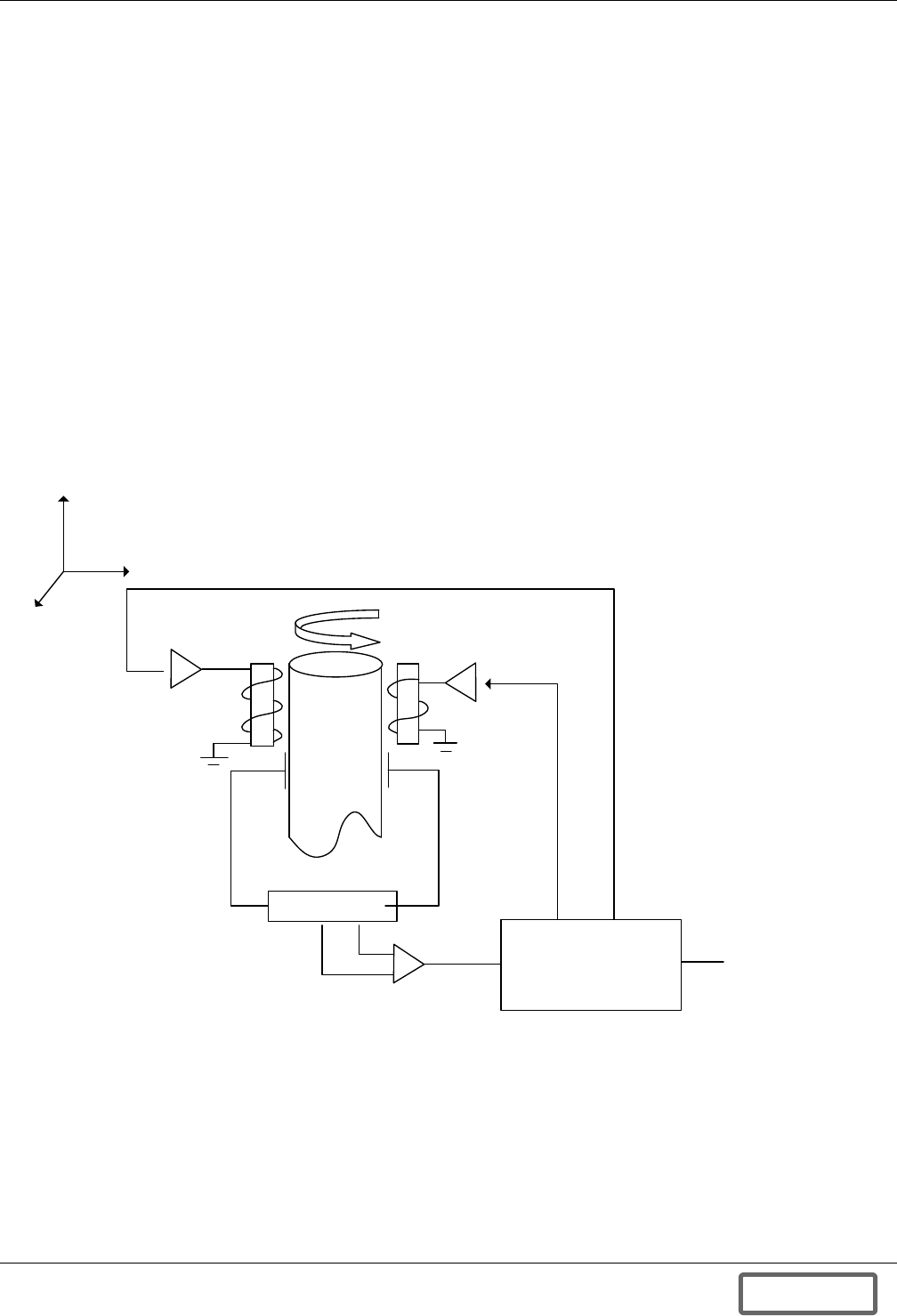
System Overview
37
5.1.7 Magnetic Levitation Module (MLM)
The Magnetic Levitation Module provides control of the active magnetic levitation hardware.
The Liebert FS has a unique active magnetic levitation system that fully levitates the flywheel-rotat-
ing group, allowing the flywheel to rotate without any physical contact. This has a number of advan-
tages over mechanical bearing systems:
• Reduced drag- Mechanical bearings have a drag that is proportional to the square of the speed.
The levitation system developed by Liebert uses the same power regardless of speed.
• Reliability and zero maintenance- The levitation system ensures there is no contact between the
rotating parts and the housing and therefore there are no components to wear out. This ensures
the unit will operate maintenance free for the life of the system.
The levitation system, works by measuring the displacement using a capacitive sensor, if the distance
needs to be adjusted; the current to the electromagnet is altered to change the displacement, each
axis is measured and controlled separately with its own capacitive sensor, electromagnet and feed-
back loop which, is controlled by the MLM. This is all done using analog control so it is very fast act-
ing and reliable. There are 5 different circuits working independently, these are: Radial: Upper X, Y;
Lower X, Y and Axial: Z Only
The principle of operation is the same in each case. The upper radial Y-axis is shown in Figure 37.
Figure 37 Schematic of the levitation system
Active Magnetic Levitation Hardware
The electromagnets and capacitive displacement sensors that provide the active magnetic levitation
are located within the flywheel module. See 5.1.7 - Magnetic Levitation Module (MLM) for a full
description of their operation.
CONDITIONER
CONTROLLER
DISPLACEMENT
SETPOINT
DISPLACEMENT SIGNAL
INFRARED EMITTER
ELECTRO-
MAGNET
AMPLIFIER
ROTOR
ELECTRO
MAGNET
CAPACITIVE
DISPLACEMENT
MEASUREMENT
AMPLIFIER
Z
X
Y
DISCONTINUED
PROD UC T
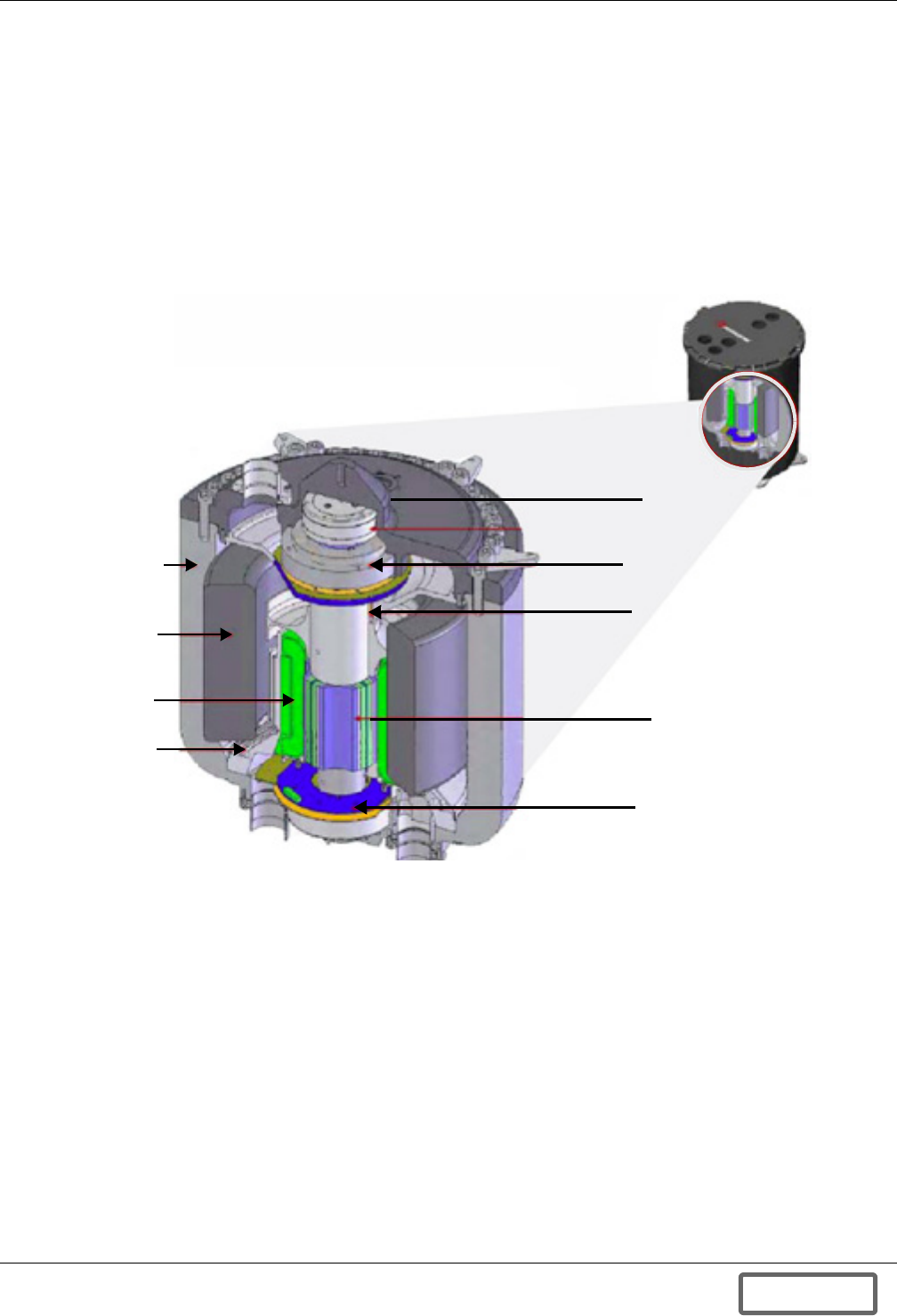
System Overview
38
5.1.8 Flywheel Module
The Flywheel Module houses several major components:
• The Rotating Group (high-speed carbon composite flywheel, high-speed shaft and rotor of the
Motor-Generator)
• The Motor-Generator (synchronous reluctance technology)
• The Molecular Vacuum Pump
• Flywheel Sensors
• Active Magnetic Levitation Hardware
• Safety System
Figure 38 Liebert FS flywheel module
Carbon Fiber
Flywheel
Liquid Cooling
Passages
Inner Housing
M-G Stator
Axial Electromagnet
Upper Radial
Electromagnet
Molecular Vacuum
System
Synchronous Reluctance
4-pole M-G Rotor
Lower Radial
Electromagnet
DISCONTINUED
PROD UC T
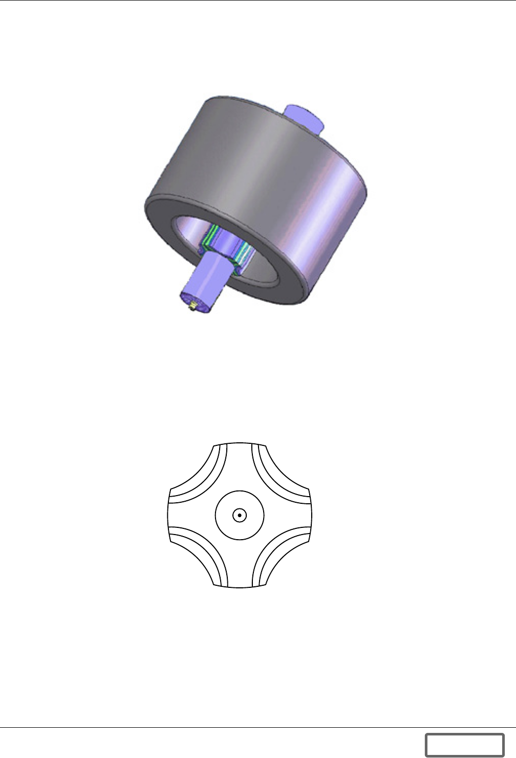
System Overview
39
5.1.9 Rotor/Flywheel—Rotating Group
The flywheel is made of carbon/glass composite. This is mounted on a metal shaft with integral
motor-rotor and together these components form the rotating group. The rotating group is magneti-
cally levitated and centered so that it does not touch any other part while in normal operation.
Figure 39 Rotating group
5.1.10 Motor Generator
The rotor is positioned within the stator in such a way that the rotor and stator provide the
motor-generator function of the Liebert FS. The stator is liquid cooled and operates within a housing
in which air has been evacuated. Together the stator and rotor operate as a synchronous reluctance
motor-generator produces enough power for the system to supply its own internal demand and to sup-
ply to the output DC bus up to the rated power. The illustration in Figure 40 shows the four poles of
the synchronous reluctance machine.
Figure 40 Cross-section of the synchronous reluctance motor rotor
DISCONTINUED
PROD UC T
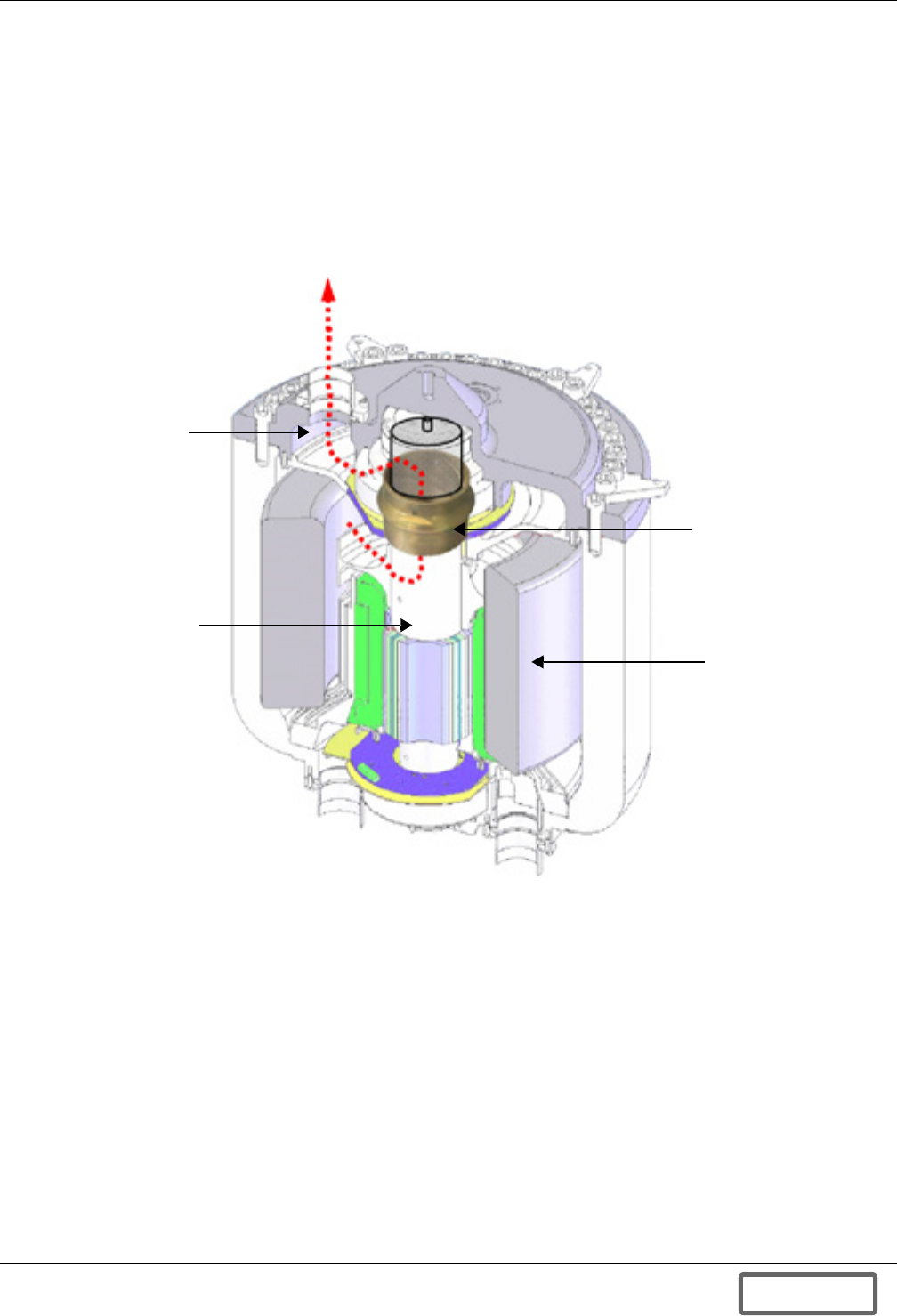
System Overview
40
5.1.11 Vacuum System
During manufacture, the vacuum chambers are evacuated and baked to remove water vapor. The vac-
uum system is then permanently sealed off to prevent any air entering the system and to remove the
possibility of accidental loss of vacuum. The Liebert FS does not require an external vacuum pump to
maintain a suitable vacuum level; the vacuum system instead relies on absorbers to maintain a rough
vacuum within the upper chamber. A zero-maintenance molecular drag pump acts with the flywheel
shaft to maintain a high-vacuum in the lower chamber, as shown in Figure 41. Vacuum levels of
much less than 100 microTorr (10-7 atmosphere) are maintained in the lower chamber. The absorber
material only needs to be recharged or changed, once every 15 years.
Figure 41 Vacuum system operation
Air and Water Vapor
Upper Chamber
Rotating Shaft
Lower Chamber
Molecular Drag Pump
DISCONTINUED
PROD UC T
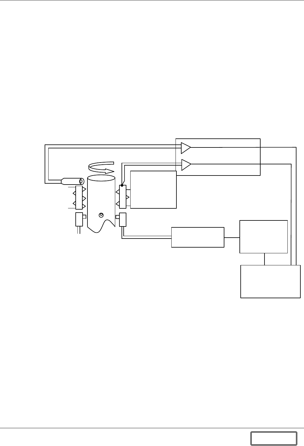
System Overview
41
5.1.12 Flywheel Sensors
Speed
The speed detection system uses an infrared emitter and a sensor to detect the rotation of the shaft. A
hole drilled through the shaft allows light to pass and is detected on the opposite side by an infrared
detector. This signal is used to detect the rotor angle, the speed and any over speed condition. The
pulsed signal passes into the 6711 DSP to be converted into a speed signal. This is then passed to the
2812 DSP. The 2812 checks for over-speed and shuts down the power electronics if this occurs. If
either of the processors lock-up, the rotor will slow down, this guarantees that on over-speed cannot
occur.
Temperature
The stator and rotor temperature detectors are thermocouples and are both conditioned in a similar
way. The stator sensor is a Type J thermocouple potted into the stator windings. The rotor sensor is a
non-contact type sensor that detects the temperature of the rotor surface and gives an output in a
Type J thermocouple format.
Figure 42 Schematic for the speed and temperature sensors
DSP 6711
TIMER INPUT
DETERMINES
SPEED
DSP 2812
DETECTS
OVERSPEED
CONDITIONER
AND DIVIDE BY 2
AMPLIFIERS, CONDITIONERS,
LINEARIZERS AND COLD
JUNCTION COMPENSATION IN
ONE CHIP
STATOR
TEMPERATURE
SENSOR
J TYPE
THERMOCOUPLE
ROTOR
INFRARED
DETECTOR
SUPPLY
FROM
CIRCUIT
BOARD
NON- CONTACT
ROTOR
TEMPERATURE
SENSOR
J TYPE
THERMOCOUPLE
OUTPUT
STATOR
WINDINGS
DISCONTINUED
PROD UC T
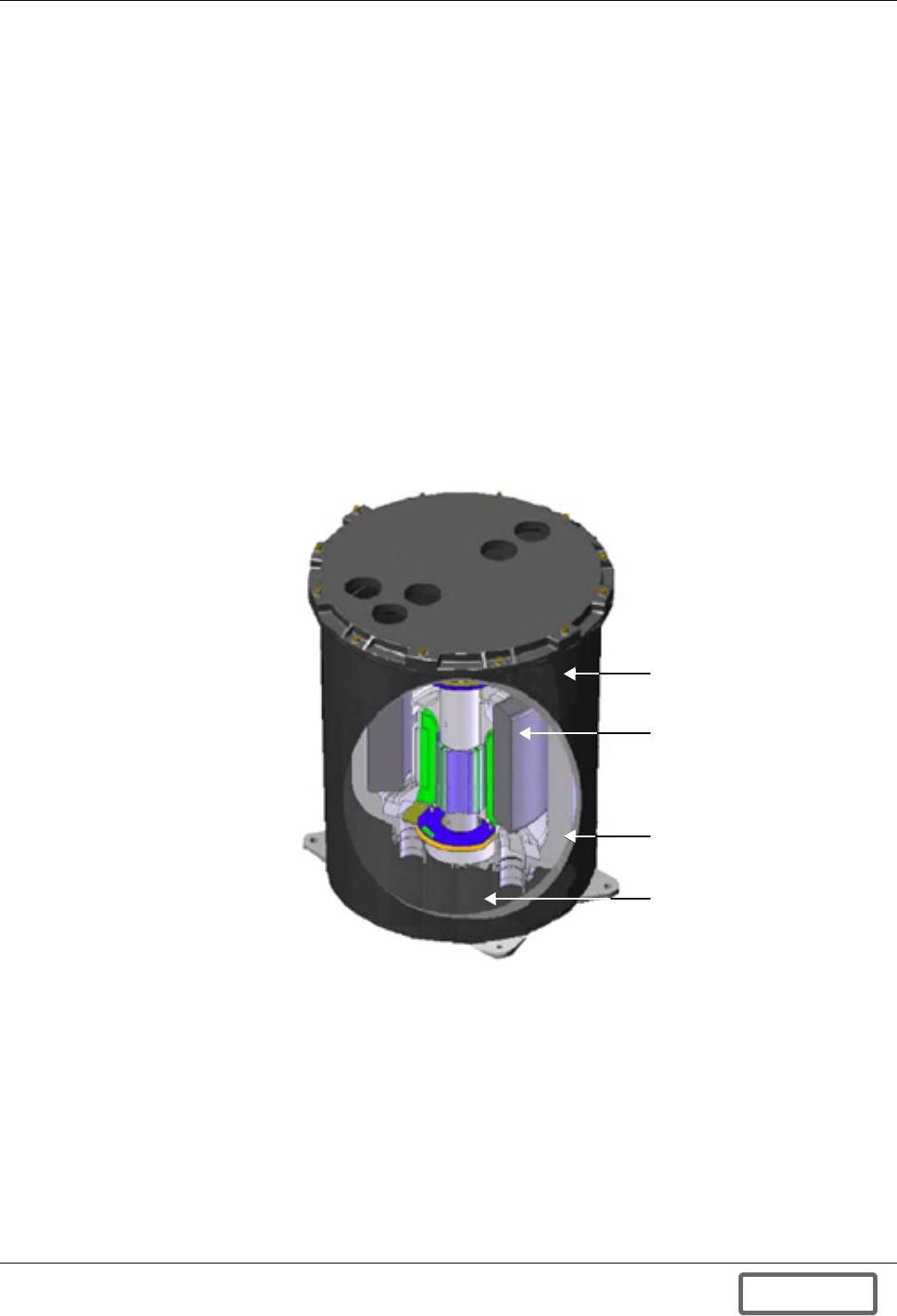
System Overview
42
5.1.13 System Safety
Every composite flywheel is inspected, spin balanced and tested to 110% over-speed in accordance
with NEMA guidelines. A patented dual-wall safety system ensures that in the unlikely event a fly-
wheel were to separate during operation, the inner housing would retain the carbon fiber. As the car-
bon fiber separates, it will expand and transfer its torque to the inner housing. The inner housing is
then allowed to rotate inside the outer housing. The cooling fluid in the outer housing, which sur-
rounds the inner housing acts as a dynamic brake. The stored energy is released in a controlled man-
ner as the flywheel / inner housing comes to a rest. The outer housing holds the entire safety system
and acts as a reservoir for the cooling fluid
The Liebert FS has been previously tested under the following fault conditions with no adverse safety
effects:
• Motor-generator AC short circuit
• DC short circuit
• Power Conversion Module failure
• Magnetic Levitation System failure
• Composite rotor failure
• Motor Rotor Failure
• Loss of Vacuum
Figure 43 Cutaway flywheel module
5.1.14 Cabinet
The Liebert FS is a compact design housed in a free-standing cabinet with a NEMA 1 construction
rating or IEC equivalent. No space is required between the back or sides of the cabinet and any walls.
The front clearance of 36" per the National Electrical Code is required. The Liebert FS accommodates
top (standard) and side entry cables. The Liebert FS can be rolled into place and go through standard
doors.
Outer Housing
Rotating Group
Inner Housing
Coolant
DISCONTINUED
PROD UC T

System Overview
43
5.1.15 Ventilation and Cooling
The Liebert FS stator and power electronics are liquid cooled with a liquid-to-air radiator. The radia-
tor within the Liebert FS package is designed for natural and forced air-cooling. Air inlets are pro-
vided from the bottom front of the Liebert FS enclosure. Air exhaust is from the top of the unit. Air
filters are provided as an option. A minimum 12" clearance overhead is required for the exhaust air-
flow.
The Liebert FS was designed with reliability in mind, the radiator is positioned to take advantage of
natural cooling and forced-air is only used when there is an elevated temperature. This also applies to
the circulating pump for the coolant, which is a highly reliable magnetically coupled centrifugal pump
that is powered with a brushless DC motor. This pump operates only when there is an elevated tem-
perature within the stator or the PCM, this extends the life of the pump to the point that it will con-
tinue to operate over the life of the unit.
5.2 List of System User-Configurable Parameters
In order to support a wide set of UPS integrations, the Liebert FS can be configured using the follow-
ing operating parameters: See 6.0 - Operation for more information on these parameters and
instructions on system setup and entering parameters to system.
Charge Voltage (Vcharge)
Vcharge is the voltage threshold above which the Liebert FS begins to charge/recharge.
Vcharge must be set at least 10VDC greater than Vreg.
• Range: 360-600VDC
• Default setting: 530VDC
Regulation Voltage (Vreg)
• Vreg is the voltage setpoint at which the Liebert FS will regulate the DC bus voltage in Discharge
Mode
• Vreg must be set at least 10 VDC less than Vcharge.
• Range: 350-590VDC
• Default setting: 520VDC
Maximum Charge Current (Max Charge Current)
• Max Charge Current is the Maximum Current the Liebert FS is allowed to draw from the UPS
DC bus.
• Range—1-50A (typical operation requires a minimum of 3A or 5A)
• Default setting—20 A
Charge Conductance (Charge Amps/Volts)
Charge amps/volts is used to set the Liebert FS charging current drawn from the UPS DC bus based
upon how much the UPS DC bus voltage is above Vcharge and so without exceeding the Max Charge
Current.
• Range—0.1-10 A/V
• Default setting: 2 A/V
DISCONTINUED
PROD UC T
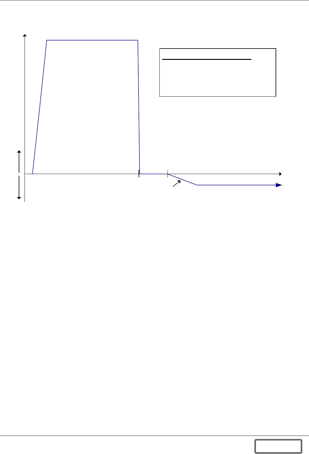
System Overview
44
Figure 44 Voltage and Inductance curve
The V-I (Voltage and Inductance) curve (see Figure 44) shows the performance characteristics and
modes of operation of the Liebert FS system based on the seven user-configurable system parameters.
Regulation Voltage Delta During Discharge (Vreg Delta 1)
Vreg Delta is the programmed amount of voltage drop from the beginning of discharge (SOC = 100%)
to the Vreg Delta TSOC.
• Range—from 0 to (Vreg - 250) VDC
(Ex: if Vreg = 500, then the Vreg Delta1 can be set between 0 and 250 VDC)
• Default setting—0 VDC
Regulation Voltage Delta Transition at State of Charge (Vreg Delta T SOC)
• Range—0-100%
• Default setting—0
User Adjustable Parameters :
1. Vcharge: 260V – 600V
2. Vreg: 250 V – 590 V
3. Charge Amps /Volt: 0.1A/V – 10A/V
4. Max Charge Current : 1A – 50A
Overload : Constant Current
Behavior: Voltage Source
Behavior: Current Sink
Vcharge
Charge
Amps/
Volt
Vreg
Charge
Mode
Discharge
Mode
Max Charge Current
DC Bus
Voltage
DC Bus
Current
DISCONTINUED
PROD UC T
System Overview
45
Regulation Voltage Delta During Discharge (Vreg Delta 2)
Vreg Delta 2 is the programmed amount of voltage drop from the Transition State of Charge to the
end of discharge (T SOC to the end of discharge (SOC = 0%)
• Range—From 0 to (Vreg - Vreg Delta1) VDC
(Ex: if Vreg = 500, and Vreg Delta1 = 50, Vreg Delta2 can be set between 0 and 200 VDC)
• Default setting—0VDC
Figure 45 Vreg delta help screen
5.3 Modes of Operation
The Liebert FS consists of a variety of operational modes. Each mode is based on a set of programmed
conditions. The Control Panel indicates the current mode and the status of that mode. Function keys
are enabled or disabled depending on the mode and status.
The Liebert FS modes are:
• OFF
• STANDBY
• STARTUP
• CHARGE
• READY
• DISCHARGE
• SHUTDOWN
• COAST
• FAULT
The Liebert FS is programmed to operate in a variety of conditional modes. The modes and status for
each mode will be indicated on the control panel. The Liebert FS is set up to transition through the
various modes with no or minimal user intervention.
NOTE
Programming of Regulation Voltage (Vreg) Delta User Configurable Parameters
• During a discharge the regulation voltage (Vreg) can be adjusted by setting the three
parameter set points described above; Vreg Delta 1, the Transition State of Charge (T SOC)
and Vreg Delta 2. (For more information on programming these parameters from the
Control Panel see 6.4.1 - Screen Tree Menu Functions)
• The Liebert FS allows for programming two different discharge slopes (Vreg Delta1 and
Vreg Delta2) and enabling a soft “handcuff” or transition before end of discharge.
(Ex: if T SOC = 20 then transition from Vreg Delta 1 to Vreg Delta 2 will take place when
80%, (Vreg TSOC), of the stored energy has been discharged, see Figure 45).
• Vreg Delta1 is used to program an initial slope from beginning of discharge to Vreg TSOC
over which the regulated voltage value will decrease and at which point a transition will
automatically occur to the secondary slope to 0% SOC at the Vreg Delta2 setpoint.
[2]V_REG******-------------------------
| ****** [5]DELTA1
|----------------+---+
100% [7]TSOC 0%
V| ******-------------
O| **
L| **---------
T|
[6]DELTA2
|
|
||
DISCONTINUED
PROD UC T
System Overview
46
5.3.1 OFF Mode
When the Liebert FS is initially powered on, it enters the OFF mode and magnetically levitates its
rotating group. A manual user command will make the system transition from OFF mode to STAR-
TUP mode if all startup conditions are met.
The Liebert FS also will enter OFF mode at the end of a shutdown and will transition automatically
from SHUTDOWN mode to OFF mode.
5.3.2 STANDBY Mode
In STANDBY Mode, the Liebert FS will be ready for Startup but be in a STANDBY Mode waiting for
user initiation of STARTUP Mode (State of Charge = 0%). By pressing the STARTUP button “F1” at
that point the Liebert FS will automatically transition into STARTUP Mode.
Figure 46 STANDBY mode diagram
The Liebert FS will be in STANDBY Mode as long as:
• Liebert FS’s SOC is less than 0%; and
• UPS DC Bus Voltage = Vcharge
• STARTUP has not been initiated
5.3.3 STARTUP Mode
In STARTUP mode, the Liebert FS will charge (increase flywheel speed) up to the minimum operat-
ing speed (State of Charge = 0%). At that point the Liebert FS will automatically transition into
CHARGE mode.
Figure 47 Startup mode diagram
The Liebert FS will be in STARTUP mode as long as:
• Liebert FS’s SOC is less than 0% and
• UPS DC Bus Voltage ≥ Vcharge.
In case the UPS DC bus voltage drops below Vcharge while in STARTUP mode, the Liebert FS will
transition automatically into COAST mode. As soon as the UPS DC bus voltage rises above Vcharge,
the Liebert FS automatically exits COAST mode and resumes STARTUP mode.
NOTE
Startup conditions are:
• UPS DC bus voltage
≥
Vcharge and
• Status is “OK”.
NOTE
In STARTUP mode, the Liebert FS will not be capable of supporting the UPS DC bus.
State of Charge < 0 State of Charge > 0
0%
100%
99.5%
UPS DC Bus Voltage = Vcharge
State of Charge < 0 State of Charge > 0
0%
100%
99.5%
Note: UPS DC Bus Voltage ≥ Vcharge
DISCONTINUED
PROD UC T
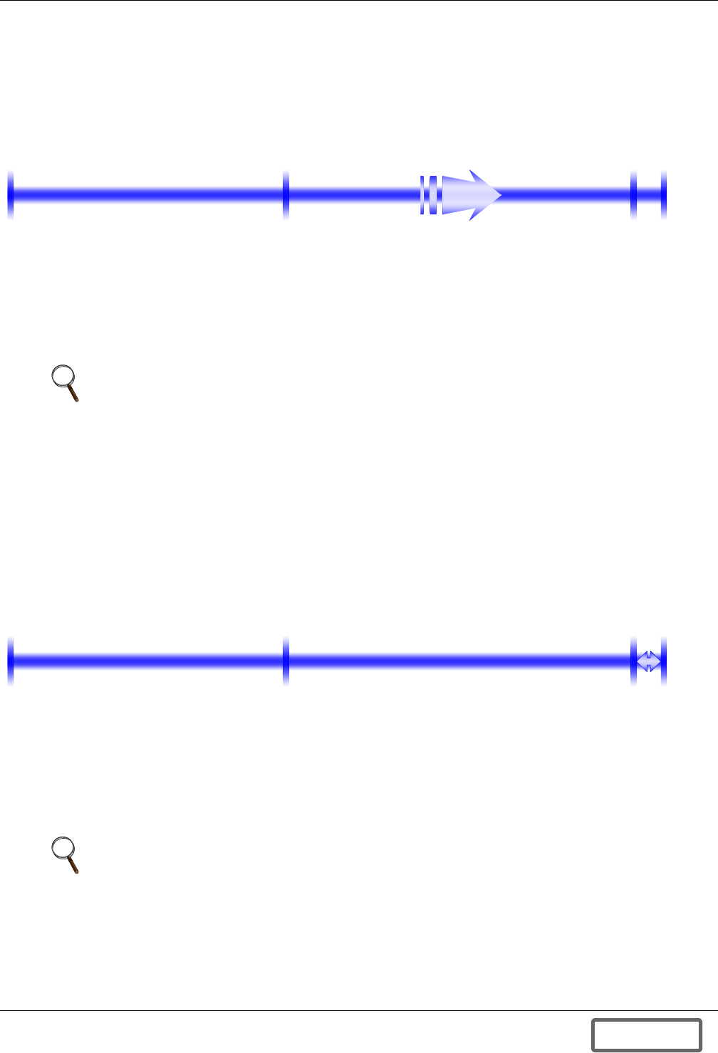
System Overview
47
5.3.4 CHARGE Mode
To charge the Liebert FS, the Liebert FS will draw power from the UPS DC bus to accelerate the fly-
wheel (as long as the UPS DC bus voltage is higher than Vcharge). In this mode, the Liebert FS State
of Charge (SOC) will progressively increase from 0% to 100%.
Figure 48 CHARGE mode diagram
The Liebert FS will be in CHARGE mode as long as:
• Liebert FS’s SOC is between 0% and 100% and
• UPS DC Bus Voltage ≥ Vcharge.
5.3.5 READY Mode
When the SOC reaches 100%, the unit will automatically transition into the READY mode. This is the
mode in which the Liebert FS will spend most of its operating time. In this mode, the Liebert FS
maintains its State Of Charge greater than 99.5%. The Liebert FS’s SOC will be allowed to drift down
to SOC = 99.5%, at which point it will transition back into CHARGE mode and charge back up to
READY mode and SOC = 100%. During normal operation, the Liebert FS will continue to automati-
cally transition between the READY and CHARGE modes to maintain a SOC between 99.5 and 100%
until either a DISCHARGE or SHUTDOWN is initiated.
Figure 49 READY mode diagram
The Liebert FS will be in READY mode as long as:
• Liebert FS’s SOC is between 99.5% and 100% and
• UPS DC Bus Voltage ≥ Vcharge.
NOTE
While in CHARGE mode, the Liebert FS will be capable of supporting the UPS DC bus.
NOTE
While in READY mode—just as in CHARGE mode—the Liebert FS will be capable of
supporting the UPS DC bus.
State of Charge < 0 State of Charge > 0
0%
100%
99.5%
Note: UPS DC Bus Voltage ≥ Vcharge
State of Charge < 0 State of Charge > 0
0%
100%
99.5%
Note: UPS DC Bus
Voltage ≥ Vcharge
DISCONTINUED
PROD UC T
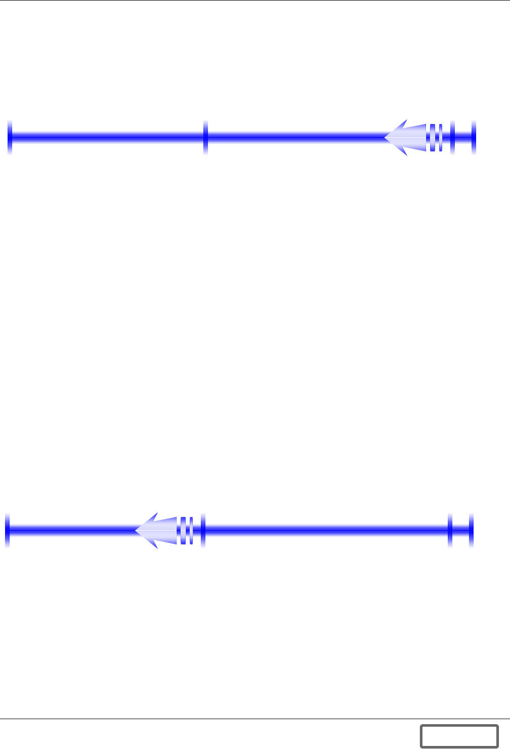
System Overview
48
5.3.6 DISCHARGE Mode
Starting from either CHARGE or READY mode, the Liebert FS will enter the DISCHARGE mode if
the UPS DC Bus Voltage goes below Vcharge. In DISCHARGE mode, the Liebert FS will regulate the
DC bus at Vreg.
Figure 50 DISCHARGE mode diagram
The Liebert FS will be in DISCHARGE mode as long as:
• UPS DC Bus Voltage < Vcharge and
• Liebert FS’s SOC is more than 0%.
The Liebert FS will leave the DISCHARGE mode and transition into CHARGE mode if the UPS DC
bus recovers (UPS DC Bus Voltage = Vcharge) before the Liebert FS’s SOC reaches 0%. In case the
UPS DC bus doesn’t recover before the Liebert FS’s SOC reaches 0%, the Liebert FS will transition
into SHUTDOWN mode.
5.3.7 SHUTDOWN Mode
In SHUTDOWN mode, the flywheel will actively spin down.
There are two ways the Liebert FS can transition into SHUTDOWN mode, by a complete discharge
and by a user command.
Following a Liebert FS Discharge Down to SOC = 0%
This is the most common SHUTDOWN process. This occurs when the Liebert FS’s SOC drops below
0% and the UPS System DC Bus voltage is less than Vcharge. If the Liebert FS entered the SHUT-
DOWN mode after leaving DISCHARGE mode, the Liebert FS will automatically transition into
STARTUP mode provided the UPS System DC Bus voltage returns to a value greater than Vcharge
(i.e., when the electric grid returns or the standby generator supplies power to the UPS).
Figure 51 SHUTDOWN mode diagram - shutdown after full discharge
State of Charge < 0 State of Charge > 0
0%
100%
99.5%
Note: UPS DC Bus Voltage = Vreg
State of Charge < 0 State of Charge > 0
0%
100%
99.5%
Note: UPS DC Bus Voltage < Vcharge
DISCONTINUED
PROD UC T
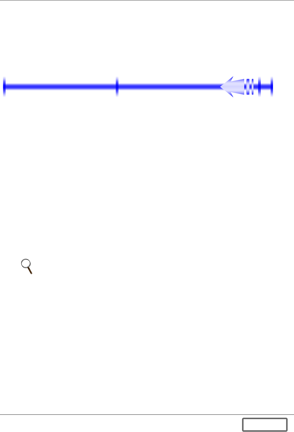
System Overview
49
Following a User Command
In any mode, except OFF mode, the user may command the Liebert FS to transition in SHUTDOWN.
While in SHUTDOWN mode, the user will still be able to command the Liebert FS to transition into
CHARGE mode (if SOC > 0%) or STARTUP mode (if SOC < 0%), provided that the UPS System DC
bus voltage is greater than Vcharge.
Figure 52 SHUTDOWN mode diagram - user-initiated shutdown
5.3.8 COAST Mode
A transition into COAST mode can occur when the UPS System DC Bus voltage drops below Vcharge
while the Liebert FS is in STARTUP mode. While in COAST mode, the Liebert FS is in an idling con-
dition where it neither draws nor generates any power.
As soon as the UPS DC Bus Voltage rises above Vcharge, the Liebert FS will automatically exit
COAST mode and resume STARTUP mode.
After five minutes in COAST Mode, if the UPS DC Bus voltage has not risen above Vcharge, the
Liebert FS will automatically transition into SHUTDOWN Mode.
5.3.9 FAULT Mode
The Liebert FS includes self-test and diagnostic circuitry such that most systems malfunctions can be
identified. In case of a system malfunction, the Liebert FS will transition into FAULT mode.
While in FAULT mode, the Liebert FS is disabled—all power electronics are turned off. Most faults
are cleared automatically by the system without the need for user intervention. Some faults do
require user action to clear the fault or to notify Liebert Services. Refer to the 8.0 - Troubleshooting
for more information).
The Liebert FS is programmed to operate in a variety of conditional modes. The modes and status for
each mode will be indicated on the control panel. The Liebert FS is set up to transition through the
various modes with no or minimal user intervention. Figure 53 illustrates the various modes of oper-
ation.
NOTE
Depending on the nature of the fault, the Liebert FS may still be capable of supporting the UPS
DC bus. Refer to 8.0 - Troubleshooting for more information.
State of Charge < 0 State of Charge > 0
0%
100%
99.5%
DISCONTINUED
PROD UC T
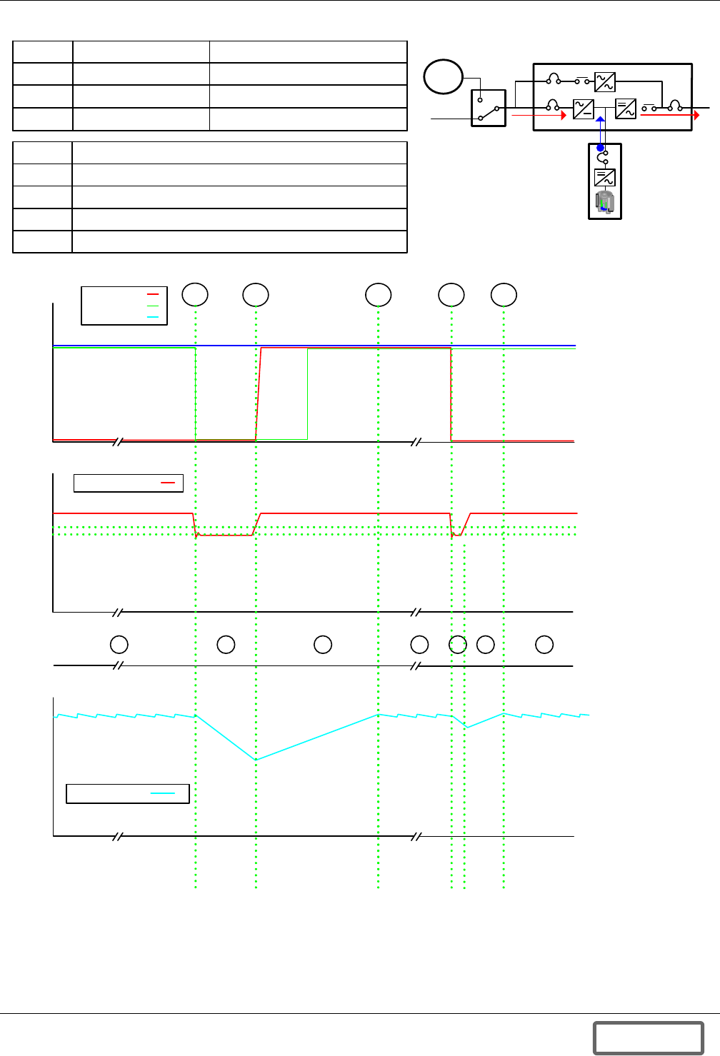
System Overview
50
Figure 53 Typical operation modes
KEY # MODE DESCRIPTION
1 READY Idle condition waiting for event
2 DISCHARGE
3 CHARGE
FS supporting the critical load
Charging to top speed
A
B
C
D
E
Gr id Supply lost , FS supporting the load
Generator Starts , A .T.S. transfers the load
FS fully charged ready to support the load
FS suppor ts the load as the A .T.S . tr ansitions back to gr id supply
FS fully charged ready to support the load
DC Bus Voltage
A B C D E
DC
VOLTAGE
AC
VOLTAGE
R. P. M .
FS Speed
ZERO
SPEED
MIN
SPEED
TOP
SPEED
FS
MODES 1 2 3 1 2 13
V Float
Vcharge
Vr eg
0 VAC
480
VAC
V Gener ator
V Grid
V Load
GEN
AC Po we r Flo w
AC Power Flow
DC Power Flow
Flywheel
Module
ATS
Grid
UPS M odul e
DISCONTINUED
PROD UC T

System Overview
51
5.4 Maintenance and Reliability
The Liebert FS is designed to require minimal preventive servicing and maintenance. There are no
user serviceable parts in the Liebert FS. Please contact a Liebert-Certified Technician before attempt-
ing to remove or service any components of the system. No bearings maintenance or replacement is
required over the life of the Liebert FS under normal operation conditions. No vacuum pump mainte-
nance or replacement is required over the life of the Liebert FS under normal operation conditions.
The optional inlet air filter in the cabinet will need to be replaced when it is sufficiently dirty as to
reduce the flow of air into the cabinet. Ambient conditions at the installation site will determine the
frequency of replacement. The Liebert FS Flywheel Module is designed for fifteen-year service life
before first scheduled maintenance. At fifteen years, the vacuum absorbers should be replaced or
regenerated.
The reliability of the Liebert FS power electronics is consistent with UPS power electronics of compa-
rable energy levels. The mechanical assemblies are of higher life and reliability than other commer-
cially available flywheel systems due to the elimination of rolling element bearings and external
vacuum-pumping systems.
DISCONTINUED
PROD UC T

Operation
52
6.0 OPERATION
6.1 Operator Controls
The Liebert FS uses a Control Panel as the primary means for an operator to interface with the sys-
tem. The Control Panel enables the operator to perform the following tasks:
Initial setup and adjustments to programmable parameters (access limited by Security
Access function):
• Set the Liebert FS Control Parameters
• Configure Liebert FS for operation with external equipment
Initial setup and adjustments to Security Access functions
• Set pass codes and access levels
Execute operational procedures:
• Startup and shutdown of the Liebert FS.
Quick view of operational status:
• View current Mode of Operation
• View current Status
Access System Status reports:
• Check temperatures and voltages
• Check vital system health indicators
Access System History
• Check number of discharges
• Check for total hours of operation
• Check for warnings and faults history
Monitor the power flow between the Liebert FS and a UPS and other Liebert FS meter
readings:
• Monitor power flow from Liebert FS to the UPS DC Bus or from UPS to the Liebert FS
• Monitor Liebert FS State of Charge
• Monitor DC Bus Voltage
• Determine if the critical load is being supplied power from the Liebert FS
• Monitor charging after discharge
DISCONTINUED
PROD UC T
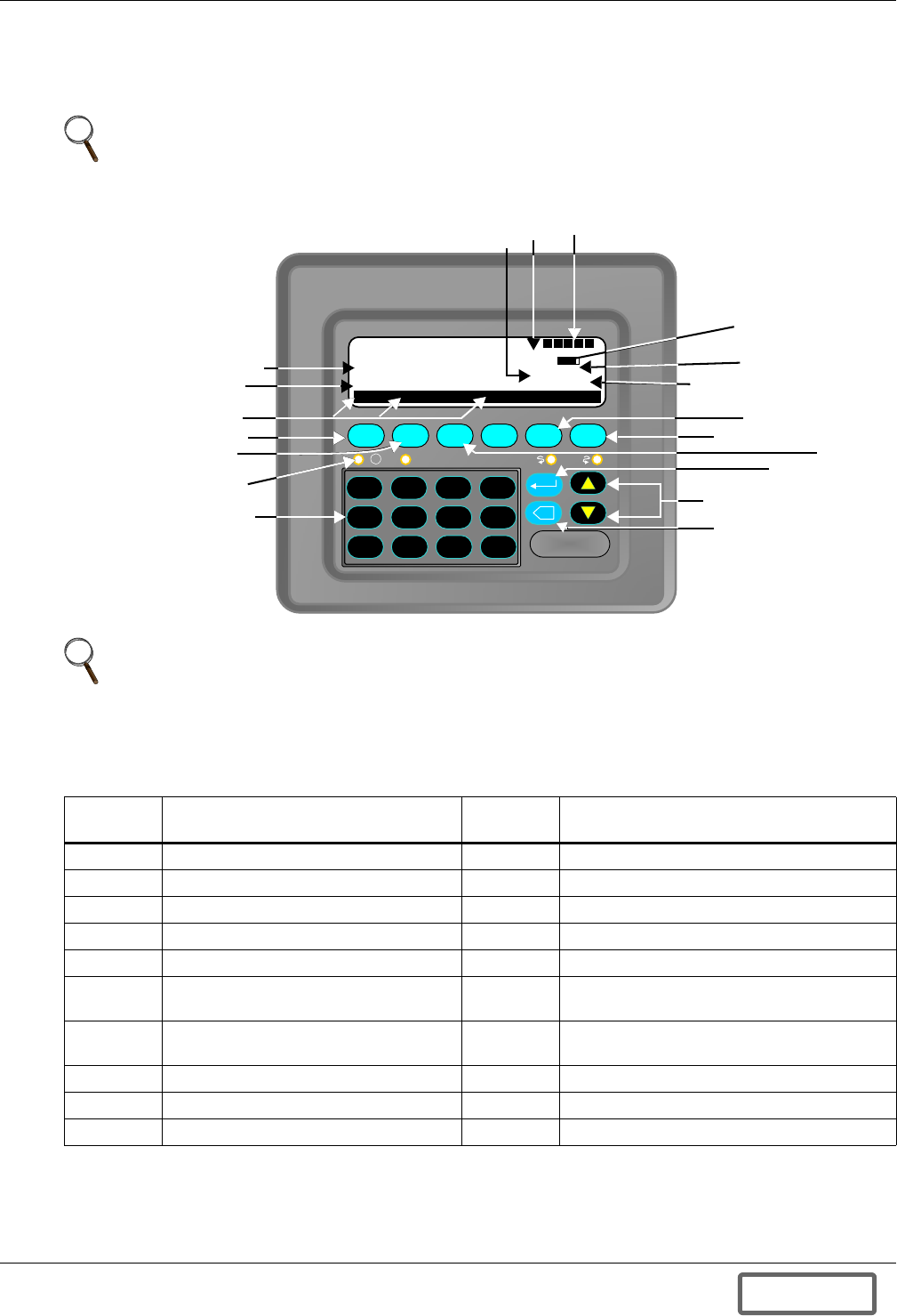
Operation
53
6.2 Control Panel
The Control Panel (see Figure 54) below represents the Control Panel on the Liebert FS. The dia-
gram is labeled as a reference for the various keys, functions and data found on the Control Panel.
Figure 54 Control panel view
Navigating the control panel is a simple process that involves responses to user prompts displayed in
the control panel. Using the panel to operate the unit will be described further in this section.
NOTE
(The actual locations of status indicators on the Control Panel display, corresponding to the
numbers below, may vary from Figure 54 depending on software version.)
NOTE
The control panel view is for reference only. Not all items will be enabled and visible on the
screen at the same time during operation
Table 4 Control panel keyboard layout (refer to Figure 54)
Keyboard
Location Operation / Navigation Keys
Keyboard
Location Screen Indication Keys
1 Numerical Keypad 11 SOC: State of Charge Bar
2 LEDs used for Servicing 12 SOC: State of Charge Value
3 F2 Shutdown key - Main Screen 13 PWR: Bus Power
4 F1 Start Up key - Main Screen 14 F5 More Information key - Fault Screen
5 Soft Menus 15 F6 Menu key - Main Screen
6STATUS: System status (see 6.2.3 -
System STATUS Indicators)16 F3 Clear Fault key - Fault Screen
7MODE: System mode (see 6.2.2 -
System MODE Indicators)17 Enter key
8 BUS: Internal DC Bus Voltage 18 Scroll Up and Down keys
9 RPM: Flywheel Rotation Speed 19 Backspace
10 Power and Options: On/Off
F1 F2 F3 F4 F5 F6
X
DISCHARGE
MODE:
STATUS:
OK
SOC :
SOC :
BUS:
PWR:
RPM:
93.3%
500 V
190 .2kW
0 1 2 3
. 4 5 6
- 7 8 9
50652
LIEBERT FS
MENU SHUTDN LOCK
I
!
D V U C P
See Table 4
for keyboard layout
89
11
12
13
14
15
16
17
18
19
1
2
3
4
5
6
7
10
DISCONTINUED
PROD UC T
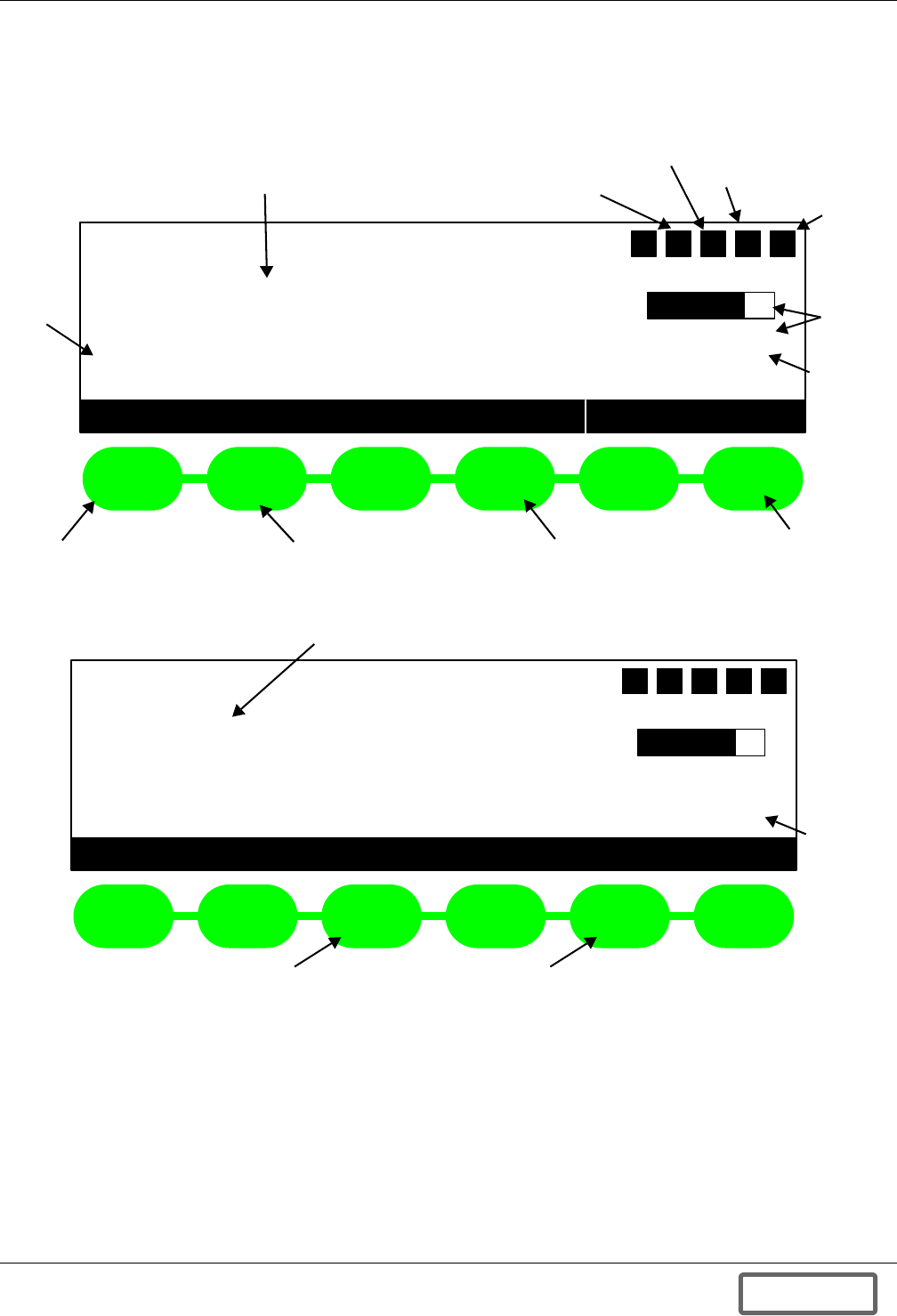
Operation
54
6.2.1 Main screen function descriptions
Figures 55 and 56. provide descriptions and locations of the information and functions available
from the Main screen and the Fault Screen.
Figure 55 Main screen functions
Figure 56 Fault screen functions
Liebert FS
48020
RPM:
SOC:
SOC:
BUS:
PWR:
73.4%
545V
12.3kW
SHUT DN MENU
F1 F2 F3 F4 F5 F6
MODE:
STATUS:
DISCHARGE
OK
START LOCK
D V U C P
Status
Message
Current Operating Mode Option Status
Current Security Level
Contactor Status
PWM
Status
Charge
Status
Internal
Bus
Voltage
Menu
Button
Panel Lock/Unlock Button
Shutdown Button
Startup Button
Liebert FS
48020
RPM:
SOC:
SOC:
BUS:
PWR:
73.4%
545V
12.3kW
CLEAR MENU
F1 F2 F3 F4 F5 F6
MODE:
STATUS:
FAULT
2 FAULTS
MORE
D V U C P
Fault Status Message
Fault Clear Button More Information
Button
Bus
Power
DISCONTINUED
PROD UC T
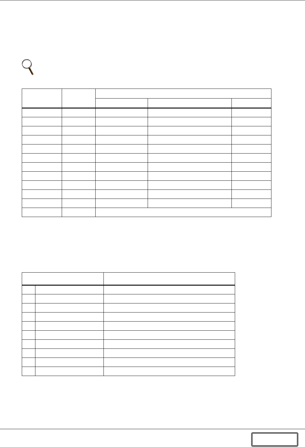
Operation
55
6.2.2 System MODE Indicators
The Liebert FS has nine modes of operation: OFF, STARTUP, CHARGE, READY, DISCHARGE,
SHUTDOWN, COAST, FAULT and STANDBY. These are displayed on the main screen of the control
panel as identified in Figure 55. Table 5 lists the system Modes along with the corresponding Con-
tactor Status, and the Conditions required to operate in these Modes: external voltage range, speed
and command.
6.2.3 System STATUS Indicators
The Liebert FS system displays multiple status conditions during operation. Table 6 shows the com-
plete list of status indicators for the Liebert FS and the corresponding condition.
NOTE:
See 5.3 - Modes of Operation for further details on modes of operation.
Table 5 Operation modes
Mode Contactor
Condition
External Voltage Speed Command
OFF Open Vext < Vchg 0 ~ 3500 —
STANDBY Open Vext > Vchg 0 ~ 200 —
STARTUP Close Vext > Vchg 200 ~ Min Speed STARTUP
CHARGE Close Vext > Vchg Min Speed ~ Max Speed STARTUP
READY Close Vext > Vchg Max Speed ~ Max Speed + 200 STARTUP
DISCHARGE Close Vext < Vchg Min Speed ~ Max Speed STARTUP
COAST Close 330 < Vext < Vchg 200 ~ Min Speed STARTUP
SHUTDOWN Open Vext < 330 200 ~ Min Speed STARTUP
Open Any Min Speed ~ Max Speed SHUTDOWN
Close Vext > 330 200 ~ Min Speed SHUTDOWN
FAULT Open Any 0 ~ Max Speed —
STANDBY — After CLRFLT
Min Speed: Minimum operating speed; State of Charge (SOC) will be 0% at this speed.
Max Speed: Maximum operating speed; State of Charge (SOC) will be 100% at this speed.
Table 6 System status indicators
Message Condition
1 OK All systems operating normally.
2 READY All systems operational and ready for startup.
3 APPLY 520*V External voltage is less than the Charge Voltage*
4 n WARNINGS Multiple warnings
5 n FAULTS Multiple faults
6 OVERSPEED Speed is higher than the Max Speed plus 200 RPM
7 TESTING VACUUM Vacuum testing at 10000 RPM
8 OPENING CONTACTOR Waiting until the current is stabilized
9 CLOSING CONTACTOR Waiting until the voltages are stabilized
10 WAIT Waiting until the voltages are stabilized
* Charge voltage is an adjustable user parameter; 520V is used only as an example.
DISCONTINUED
PROD UC T
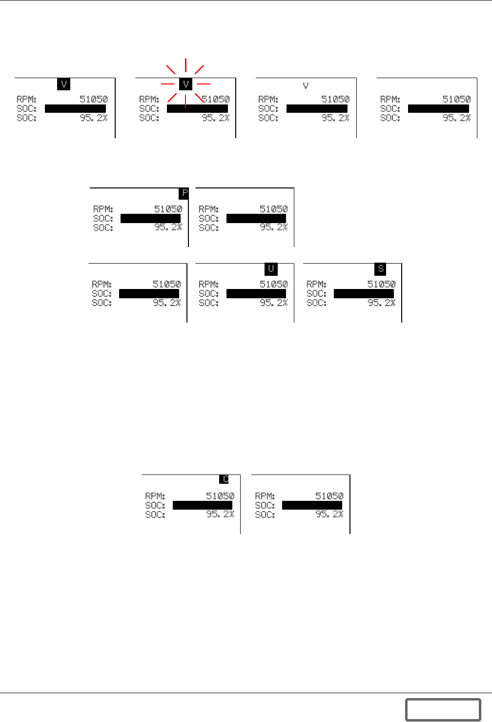
Operation
56
6.2.4 Other Status Indicators
The Liebert FS system displays additional indicators during operation.
• Option Status; DCM or VIB (example: V abbreviation for VIB enabled
• Security Levels
• PWM: Pulse Width Modulation Status (ON or OFF)
• SOC: State of Charge (0-100%)
SOC shows a relative energy stored in the system. SOC is determined with the following equa-
tion. It is 100% at Max Speed. A negative SOC means the required energy in % to get to the
CHARGE state.
• Contactor Status
• LOCK/UNLOCK of the Control Panel
Control Panel can be locked or unlocked for security purposes. Locking or unlocking the display panel
requires a user password to confirm. See 6.3.2 - Password.
• PWR: Bus Power
PWR shows the DC power transfer in kW. Positive power indicates DISCHARGE and negative
power indicates CHARGE, respectively.
RPM:
SOC:
SOC:
RPM:
SOC:
SOC:
RPM:
SOC:
SOC:
RPM:
SOC:
SOC:
51050
95.2%
51050
95.2%
51050
95.2%
51050
95.2%
V
VV
Operative Inoperative Disabled Uninstalled
Default setting
PWM on PWM off
RPM:
SOC:
SOC:
51050
95.2%
P
RPM:
SOC:
SOC:
51050
95.2%
RPM:
SOC:
SOC:
51050
95.2%
RPM:
SOC:
SOC:
51050
95.2%
U
RPM:
SOC:
SOC:
51050
95.2%
S
READ ONLY USER SERVICE
Default setting
SOC rpm2MinRpm2
–
MaxRpm2MinRpm22()
–
------------------------------------------------------------------ 100×=
51050
95.2%
Closed Open
RPM:
SOC:
SOC:
51050
95.2%
C
RPM:
SOC:
SOC:
DISCONTINUED
PROD UC T
Operation
57
6.3 Security Access
6.3.1 Security Levels
The Liebert FS software has two security levels: READ-ONLY and USER. Security levels restrict
access to system resources, such as EEPROM parameters, terminal commands and display panel
functions. From the Main Screen, Figure 55, the display can be locked at any time to prevent use of
Control Panel. Pressing F4 button under “LOCK” will prompt the user to enter a password to “LOCK”
the system. Once locked F4 will now read “UNLOCK” and pressing this will prompt you to enter the
Password to the system so that the user will be able to operate the Control Panel and adjust system
parameters and settings.
6.3.2 Password
READ-ONLY level has no password and it is default level at reset.
The USER level password is user-configurable and saved in EEPROM. The default USER level pass-
word is “1234”, and the password should be between 3 - 12 digits.
6.3.3 EPROM (System) Parameters
EEPROM (system) parameters can be accessed through display panel or terminal commands. They
can be read and written through terminal or display panel, but accessible parameters are limited by
security levels. The parameters for each level have different number range. Unused numbers are
reserved for future usage.
6.4 Menu Tree and Navigation
6.4.1 Screen Tree Menu Functions
The following diagram shows all of the screens accessible from the control panel and the path to bring
up these screens. The screens are used for configuring the Liebert FS for operation and accessing data
current and historical data on its performance. The screens are organized by five primary function
areas; Parameters, View, Security, About, and Tools. These are displayed on the Main Menu screen.
Some of the screens require User level or Service level passwords to access as shown in the legend
below. Refer to 6.3 - Security Access for more information on this subject.
Table 7 EEPROM parameter number ranges
Security Level Parameter Number Range
Read-Only 0 ~ 99
User (Editable) 0 ~ 99
Table 8 PCMC parameters, read-only and user (Liebert FS software)
No Parameter Name Unit Default Minimum Maximum
1 Vcharge Setpoint V 530 360 800
2 Vreg Setpoint V 520 350 790
3 Icharge Max Setpoint A 30 1 50
4 Amps per Volt Setpoint A/V 20 1 50
5 Vreg Delta Setpoint 1 V 0 0 150
6 Vreg Delta Transition (SOC) % 0 0 100
7 Vreg Delta Setpoint 2 V 0 0 150
DISCONTINUED
PROD UC T
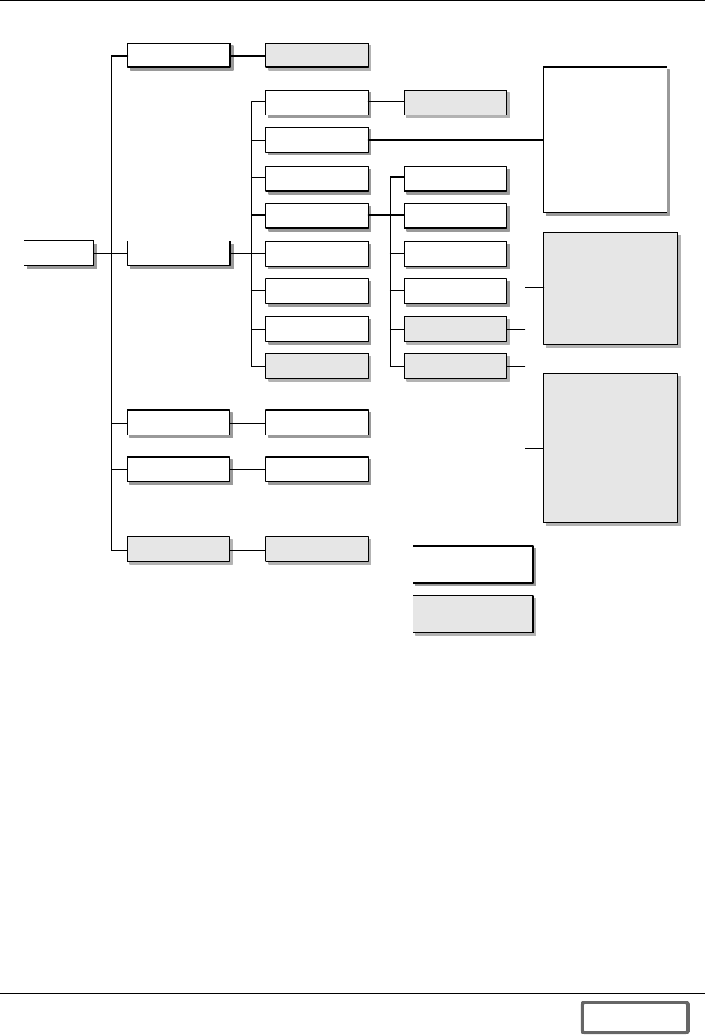
Operation
58
Figure 57 Menu tree
User/ Adv
Time/ Date
Temperatures
Voltages
History
Options
Charge
Electrical
Network
Vitals
Password Input
S/N
Reboot
Security
About
Tools
ViewMenu
Discharge
Warning
Fault
Vitals
Counters
View/ Set
Parameters
Rotor
Stator
IGBT
PCM/ PPM
MLM/ MCM
Cabinet
24V PS #1
24V PS #2 *
* FS models only
Max Drag Power
Min Drag Power
Last 10k Drag
Max Miser
Max Runout
Contact Closure
Shutdown to Off
Bootup Count
Hours since bootup
Pump On-time
Fan 1 On-time
Fan 2 On-time*
* FS, Serial P or N
units only
All Level Menu
User Level Menu
LEGEND
DISCONTINUED
PROD UC T
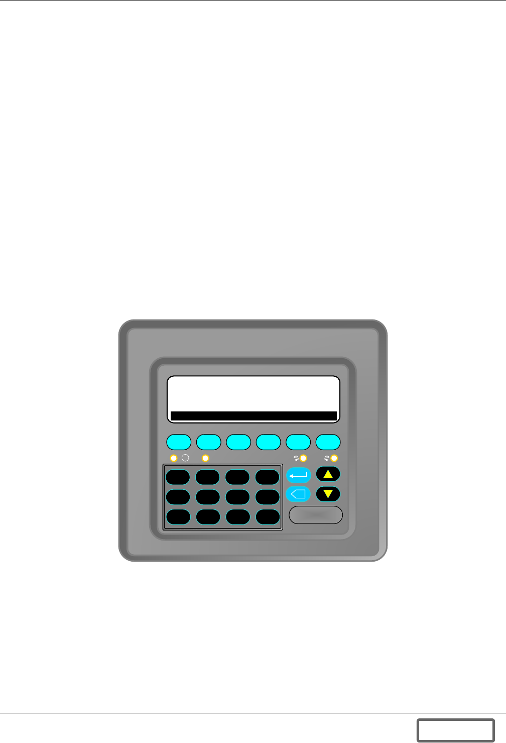
Operation
59
6.4.2 Navigation and Operation of Control Panel
Navigation of the menu screens is simple and intuitive. From the Main Screen, also referred to as
“Home”, menu functions and screens can be accessed by using the function keys and the numeric key-
pad. The function keys, F1- F6, initiate certain system functions and Modes; STARTUP, SHUT-
DOWN and also perform certain menu screen functions; DONE, PREVIOUS, NEXT, and HOME. The
up and down arrows on the control panel enable the user to scroll up or down certain menus. The
numeric keypad can be used to enter values for system setup and the Enter and Backspace keys to
enter numbers or backspace to change entry. Pressing F6 or DONE completes the entry process.
Always double check by going back to the previous screen to verify the entry is complete and accurate.
To access the Main Menu press the F6 button below the “Menu” option in the lower right. When
pressed, the “Menu” key, will display the Main Menu screen as shown in Figure 58. From this screen
each of the submenus may be accessed, provided the user has security access where needed, refer to
Figure 57.
Each screen in the menu tree will show numbers in front of the subject if more information is avail-
able at the next menu level. Pressing the number for the subject using the numeric keypad will bring
up that screen. If the subject is preceded by a double arrow symbol (>>) instead of a number no fur-
ther information is available or the parameter may not be modified without security access.
At each screen and level in the menu tree, when finished accessing data or changing system parame-
ters, the user may select DONE using the function keys to move back to the prior screen in the menu
or when available press HOME, F5, to return to the Main Screen. On some screens such as in the His-
tory screens you will be able to access additional screens of data recorded by pressing NEXT, see
Figures 70 and 71.
Figure 58 User level main menu screen
6.4.3 System Setup and Parameter Access
Setting up the Liebert FS:
In order to operate the system the system parameters must be configured for the application. The sys-
tem parameters or “EEPROM” parameters can be accessed by first pressing MENU, F6, and the num-
ber one (1) button on the Control Panel keypad for the PARAMETERS screen. Liebert FS software
has two kinds of access screen according to the security level.
In READ-ONLY mode, seven basic parameters can be monitored. Modifying the parameters in this
mode is not allowed. In this mode the parameters will have double arrow symbols to the left of the
parameters.
F1 F2 F3 F4 F5 F6
X
1. PARAMETERS
2. VIEW
3. SECURITY
4. ABOUT
5. TOOLS
0123
. 4 5 6
- 7 8 9
MENU>
DONE
I
!
DISCONTINUED
PROD UC T
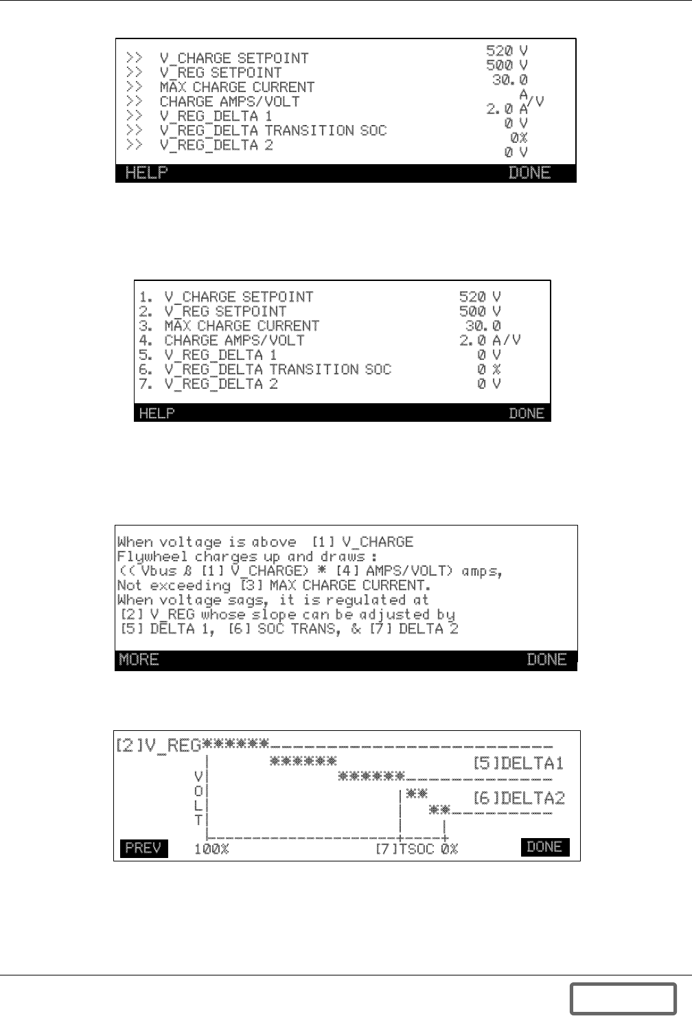
Operation
60
Figure 59 READ ONLY level parameter view screen
In the USER mode, below the 7 basic parameters can be modified, see 6.3.2 - Password for access
level and passwords. Pressing the corresponding number to the parameter to the left of the number
will take you to the parameter setup screen for that particular parameter.
Figure 60 USER level or above parameter edit screen
In setting the parameters there is a help screen to guide the user through the setup and help visualize
the operation the system when utilizing this parameter. The help screens are displayed in
Figures 61 and 62. The help screen also describes the other system parameters used in operation.
Figure 61 HELP screen for User Setup Parameters
Figure 62 Graphical HELP screen for VREG DELTA1, VREG TSOC, and VREG DELTA2 Transition setup
(Pressing the “MORE” button, F1, from Figure 5-8. accesses this screen)
>>
>>
>>
>>
>>
>>
>>
V_CHARGE SETPOINT
V_REG SETPOINT
MAX CHARGE CURRENT
CHARGE AMPS/VOLT
V_REG_DELTA 1
V_REG_DELTA TRANSITION SOC
V_REG_DELTA 2
520 V
500 V
30.0
A
2.0 A
0 V
0%
0 V
/V
HELP DONE
1.
2.
3.
4.
5.
6.
7.
V_CHARGE SETPOINT
V_REG SETPOINT
MAX CHARGE CURRENT
CHARGE AMPS/VOLT
V_REG_DELTA 1
V_REG_DELTA TRANSITION SOC
V_REG_DELTA 2
520 V
500 V
30.0
2.0 A
0 V
0 %
0 V
/V
HELP DONE
When voltage is above [1] V_CHARGE
Flywheel charges up and draws :
(( Vbus – [1] V_CHARGE) * [4] AMPS/VOLT) amps,
Not exceeding [3] MAX CHARGE CURRENT.
When voltage sags, it is regulated at
[2] V_REG whose slope can be adjusted by
[5] DELTA 1, [6] SOC TRANS, & [7] DELTA 2
DONE
MORE DONE
[2]V_REG******-------------------------
|
|
|
|
|
|
************-------------
|
|
|
****---------
|
---------------------+----+
V
O
L
T
100% [7]TSOC 0%
[5]DELTA1
[6]DELTA2
PREV DONE
DISCONTINUED
PROD UC T
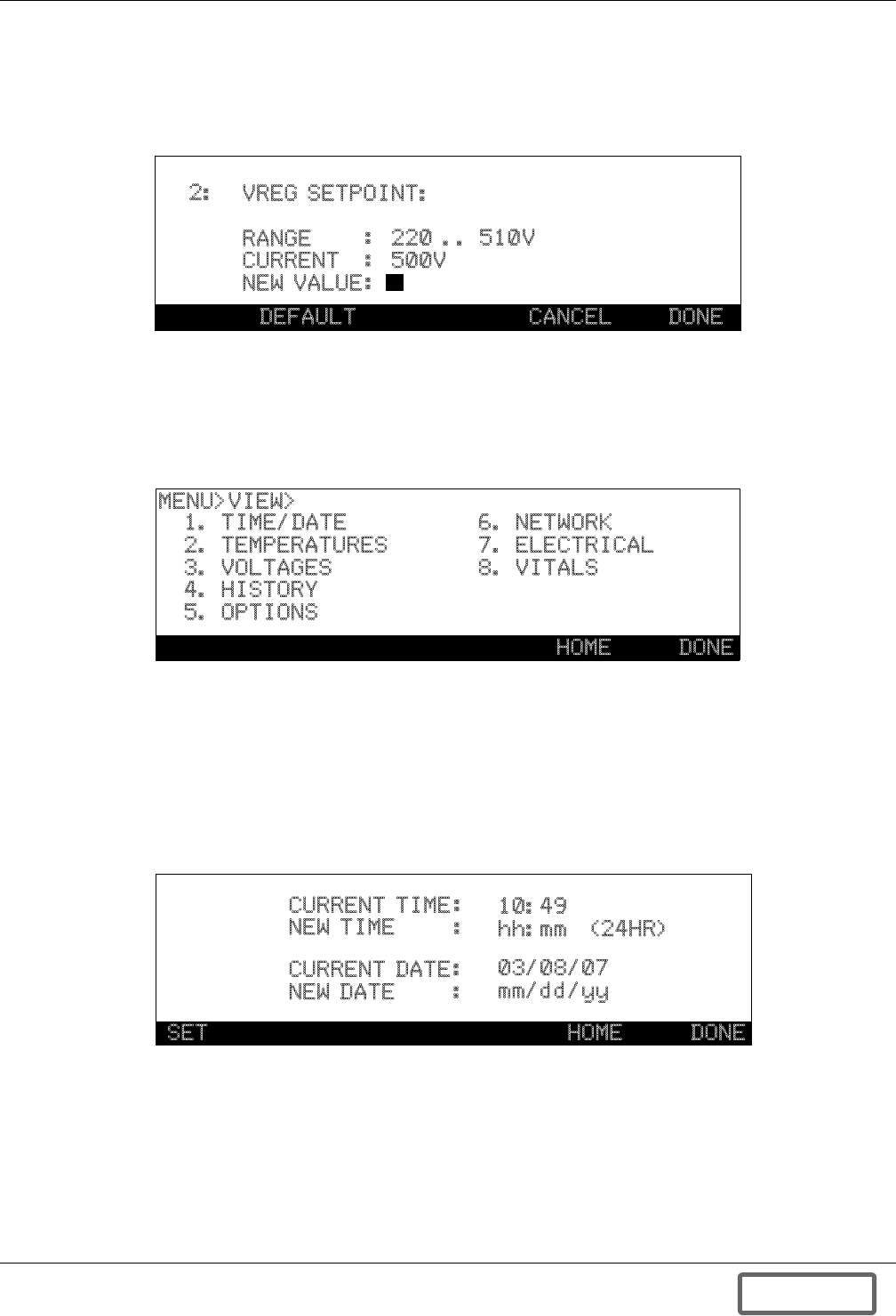
Operation
61
Each EEPROM parameter has its own screen which contains parameter description, data range, cur-
rent value and default value button. Default button shows the default value for the parameter. From
this screen the UP/DOWN arrow keys can used to move between parameters. The UP/Down arrow
will increase/decrease the parameter number, respectively.
Figure 63 USER or higher level parameter selection for view/edit
6.4.4 View
Functions in MENU > VIEW display various system status including real-time and statistical data.
The menu path is represented in the upper left hand corner of the screen and lets you know your cur-
rent screen location in the menu tree. You can select the function by entering the number.
Figure 64 VIEW menu
6.4.5 Time/Date
In MENU>VIEW>TIME/DATE, system time is displayed and can be adjusted. However, USER secu-
rity level or higher is required to adjust the time or date, see 6.3.2 - Password. Pressing SET button
changes to the edit mode. Cursor will blink on NEW TIME. You can type in new time data or move to
NEW DATE by UP/DOWN arrow button. Moving to NEW DATE should be made before typing in any
digits. All digits for time (4 digits) or date (6 digits) should be typed in before ENTER or you will get
the INVALID INPUT error message.
Figure 65 TIME/DATE set
2: VREG SETPOINT:
RANGE
CURRENT
NEW VALUE
:
:
:
220 .. 510V
500V
DEFAULT CANCEL DONE
1. TIME/DATE
2. TEMPERATURES
3. VOLTAGES
4. HISTORY
5. OPTIONS
6. NETWORK
7. ELECTRICAL
8. VITALS
MENU>VIEW>
HOME DONE
CURRENT TIME
NEW TIME
CURRENT DATE
NEW DATE
:
:
:
:
10:49
hh:mm (24HR)
03/08/07
mm/dd/yy
SET HOME DONE
DISCONTINUED
PROD UC T
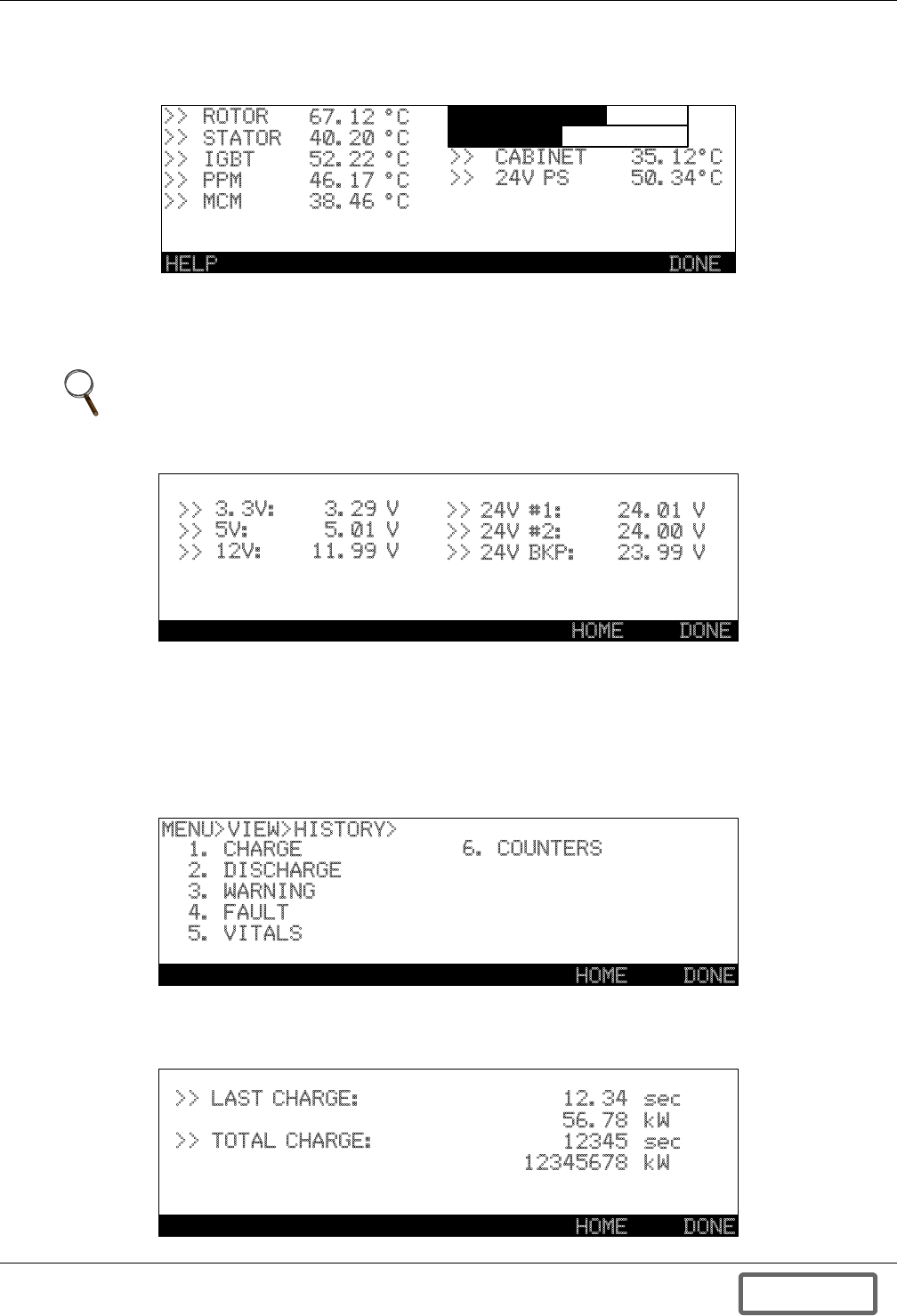
Operation
62
6.4.6 Temperatures
MENU>VIEW>TEMPERATURES shows the temperatures of various system parts.
Figure 66 Temperature view
6.4.7 Voltages
MENU>VIEW>VOLTAGES shows the major power supply voltages on the controller board. These
values are updated continuously.
Figure 67 Figure 5-14. Voltages view
6.4.8 History
The Liebert FS records and stores a limited history of the following items; CHARGE, DISCHARGE,
WARNING, FAULT, VITALS, and COUNTERS which are listed in the main History menu screen.
(See Figure 69). In the event list screens, Figures 71 through 73, users may move between pages
using the PREV and NEXT buttons. History data can be cleared by RESET button. SERVICE or
higher level is required to reset the list.
Figure 68 History view
• Charge: The most recent charge (LAST CHARGE) is displayed in time (sec.) and energy (kW) on
this screen as are the accumulated charge time/energy (TOTAL CHARGE). (See Figure 69.)
Figure 69 Charge history
NOTE
If an earlier model Liebert FS, serial number P or N, flywheel system has been upgraded with
this software, it will display only the 24V power supply voltage.
>>
>>
>>
>>
>>
ROTOR
STATOR
IGBT
PPM
MCM
67.12 °C
40.20 °C
52.22 °C
46.17 °C
38.46 °C
>>
>>
CABINET
24V PS
35.12°C
50.34°C
DONEHELP
>>
>>
>>
>>
>>
>>
3.3V:
5V:
12V:
3.29 V
5.01 V
11.99 V
24V #1:
24V #2:
24V BKP:
24.01 V
24.00 V
23.99 V
HOME DONE
MENU>VIEW>HISTORY>
1. CHARGE
2. DISCHARGE
3. WARNING
4. FAULT
5. VITALS
6. COUNTERS
HOME DONE
HOME DONE
>> LAST CHARGE:
>> TOTAL CHARGE:
12.34
56.78
12345
12345678
sec
kW
sec
kW
DISCONTINUED
PROD UC T
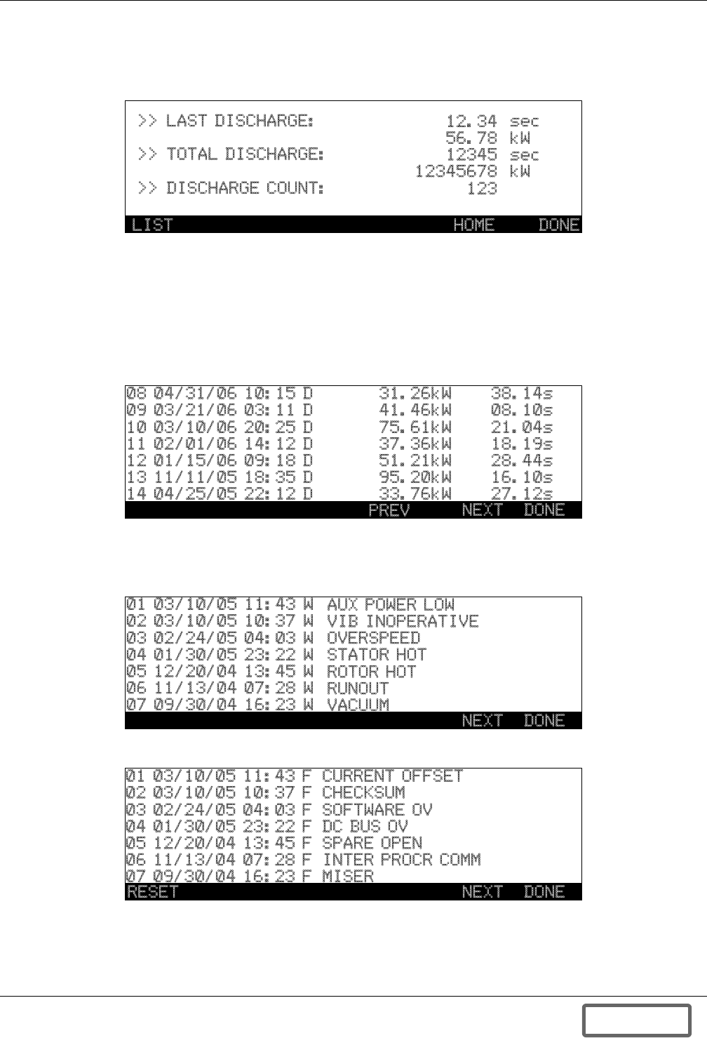
Operation
63
• Discharge: The most recent discharge (LAST DISCHARGE) is displayed in time (sec.) and energy
(kW) on this screen as are the accumulated discharge time/energy (TOTAL DISCHARGE) and the
number of times system has discharged (DISCHARGE COUNT). (SeeFigure 70.)
Figure 70 Discharge history
• A Discharge History event list screen, Figure 72, is available and shows the event number, date
(month./day/year), time of event (00:00-24:00) average power (kW), and duration of discharge (sec-
onds). The recorded events are sequentially numbered and listed from most recent to last. The let-
ter “D” after the time indicates that this is the DISCHARGE History screen.
The first screen has the function options of NEXT or DONE viewing. The next page will have the
function button options of PREV (Previous), NEXT or DONE.
Figure 71 Discharge History, Event list screen
• Warning/Fault: Liebert FS software holds 35 warning and fault event information, respec-
tively. Seven warnings/faults are displayed in a single screen.
Figure 72 Warning history, Event list screen
Figure 73 Fault history, Event list screen
HOME DONE
12.34
56.78
12345
12345678
123
sec
kW
sec
kW
>> LAST DISCHARGE:
>> TOTAL DISCHARGE:
>> DISCHARGE COUNT:
LIST
08 04/31/06 10:15 D
09 03/21/06 03:11 D
10 03/10/06 20:25 D
11 02/01/06 14:12 D
12 01/15/06 09:18 D
13 11/11/05 18:35 D
14 04/25/05 22:12 D
31.26kW
41.46kW
75.61kW
37.36kW
51.21kW
95.20kW
33.76kW
38.14s
08.10s
21.04s
18.19s
28.44s
16.10s
27.12s
NEXT DONE
PREV
NEXT DONE
01 03/10/05 11:43 W
02 03/10/05 10:37 W
03 02/24/05 04:03 W
04 01/30/05 23:22 W
05 12/20/04 13:45 W
06 11/13/04 07:28 W
07 09/30/04 16:23 W
AUX POWER LOW
VIB INOPERATIVE
OVERSPEED
STATOR HOT
ROTOR HOT
RUNOUT
VACUUM
NEXT DONE
01 03/10/05 11:43 F
02 03/10/05 10:37 F
03 02/24/05 04:03 F
04 01/30/05 23:22 F
05 12/20/04 13:45 F
06 11/13/04 07:28 F
07 09/30/04 16:23 F
CURRENT OFFSET
CHECKSUM
SOFTWARE OV
DC BUS OV
SPARE OPEN
INTER PROCR COMM
MISER
RESET
DISCONTINUED
PROD UC T
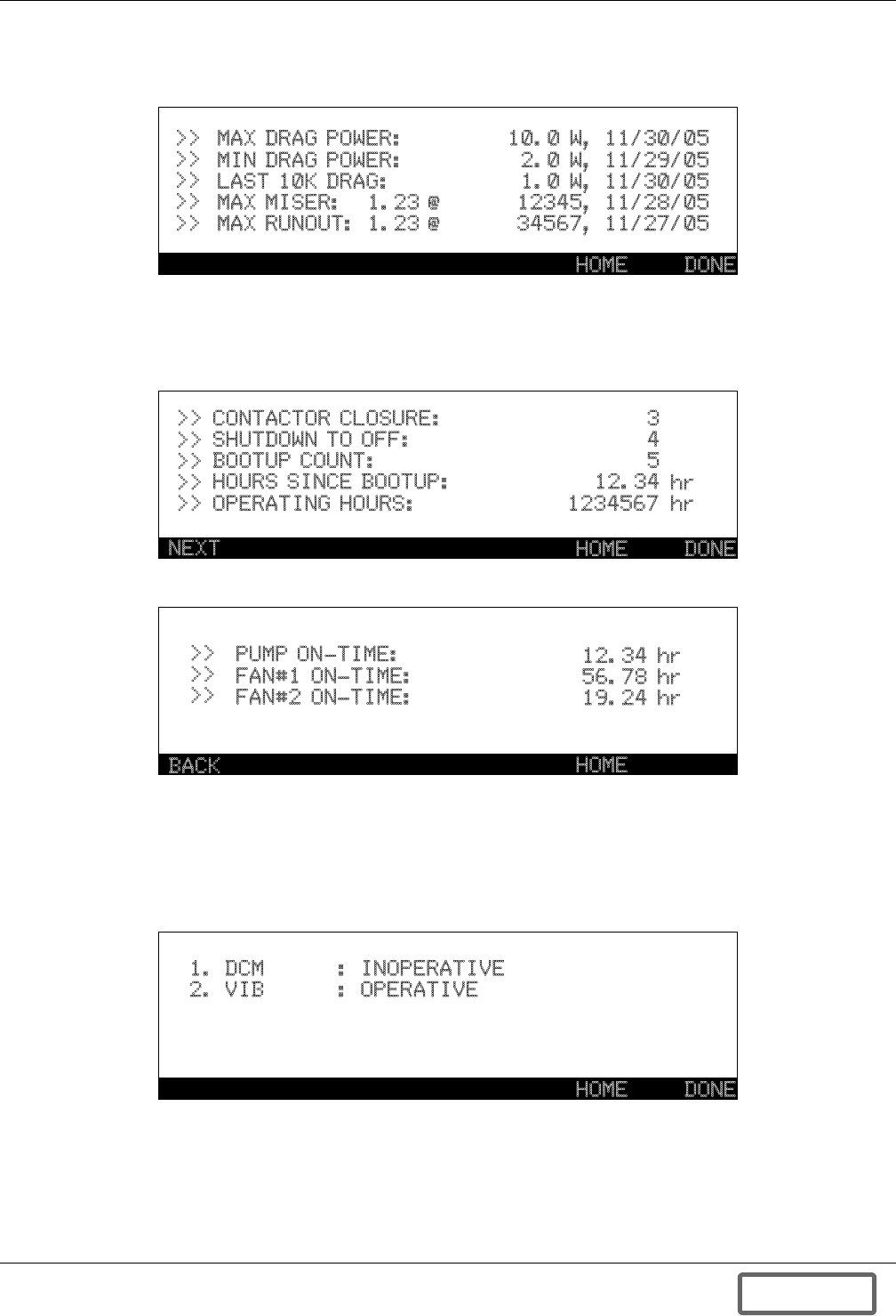
Operation
64
• Vitals (USER or above): Key system efficiency and performance measurements are displayed in
Max/Min measurements along with the date recorded.
Figure 74 Vitals history view
• Counters (USER or above) provide totals of run time hours; system and components, and numbers
of startup and shutdown events; contactor closures and bootup. OPERATING HOURS is the total
operating hours in the CHARGE/ DISCHARGE/ READY mode.
Figure 75 Counters
Figure 76 Counters - screen 2
6.4.9 Options
Each option, if installed, can be enabled by pressing its number and its status will then be displayed.
Additional information on setup and operation of these options is available in the related section of
this manual.
Figure 77 Options view
HOME DONE
MAX DRAG POWER:
MIN DRAG POWER:
LAST 10K DRAG:
MAX MISER:
MAX RUNOUT:
1.23 @
1.23 @
10.0 W, 11/30/05
2.0 W, 11/29/05
1.0 W, 11/30/05
12345, 11/28/05
34567, 11/27/05
>>
>>
>>
>>
>>
HOME DONE
>>
>>
>>
>>
>>
CONTACTOR CLOSURE:
SHUTDOWN TO OFF:
BOOTUP COUNT:
HOURS SINCE BOOTUP:
OPERATING HOURS:
3
4
5
12.34
1234567
hr
hr
NEXT
HOME
>>
>>
>>
PUMP ON-TIME:
FAN#1 ON-TIME:
FAN#2 ON-TIME:
12.34 hr
56.78 hr
19.24 hr
BACK
HOME DONE
1. DCM : INOPERATIVE
2. VIB : OPERATIVE
DISCONTINUED
PROD UC T
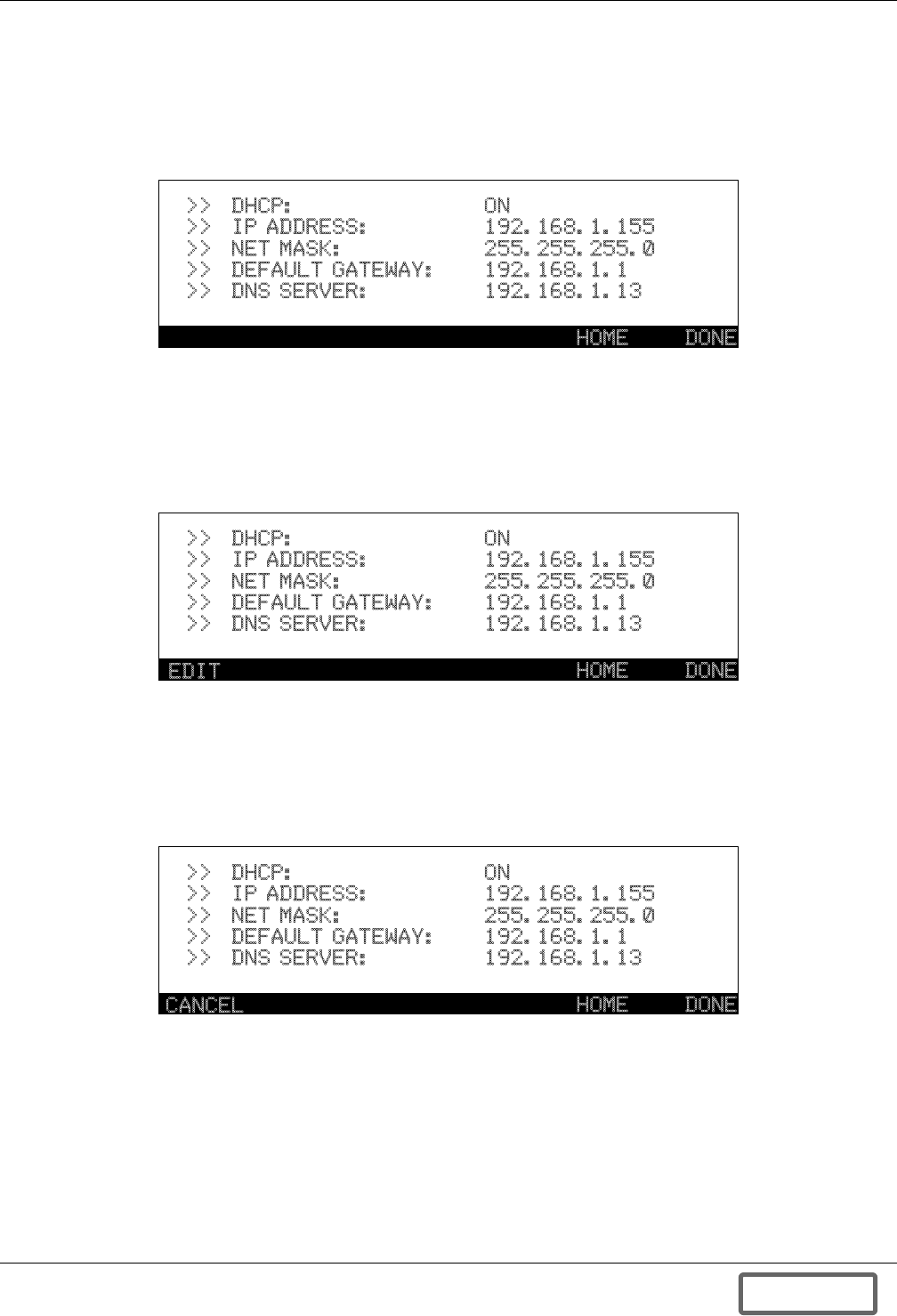
Operation
65
6.4.10 Network—Requires DCM Option
The Network view screen displays the addresses of the DCM. Static address settings can be entered
using the keypad into this screen. If this option is installed, reference the Liebert Data Collection
Module (DCM) Option Manual for more information on setting up the DCM on a network and or
assigning IP addresses. Figure 78 shows the Network screen in a read-only mode.
Figure 78 Networks view
By entering a Password to access the User level mode (see 6.3.2 - Password), you can edit this func-
tion. Pressing the EDIT button, F1, will place the system in the edit mode. The DHCP must be dis-
abled or turned OFF to proceed with setting IP addresses and other settings. After pressing EDIT you
will see up/down arrows next to the DHCP ON value. Pressing the up or down arrows on the keypad
will allow you to turn OFF or ON this function.
Figure 79 Networks view, Edit DHCP
Once you have turned DHCP OFF, press EDIT again and now you will see numbers next to each of
the settings. Pressing the corresponding number will allow you to enter or change that value. At any
time you may press CANCEL to cancel the changes. Once the changes or entries are complete, press
APPLY to complete entry process. Pressing APPLY will reboot system and in a few minutes the sys-
tem will display the new screen.
Figure 80 Networks view, Edit Settings (Service level)
HOME DONE
>>
>>
>>
>>
>>
DHCP:
IP ADDRESS:
NET MASK:
DEFAULT GATEWAY:
DNS SERVER:
ON
192.168.1.155
255.255.255.0
192.168.1.1
192.168.1.13
HOME DONE
>>
>>
>>
>>
>>
DHCP:
IP ADDRESS:
NET MASK:
DEFAULT GATEWAY:
DNS SERVER:
ON
192.168.1.155
255.255.255.0
192.168.1.1
192.168.1.13
EDIT
HOME DONE
>>
>>
>>
>>
>>
DHCP:
IP ADDRESS:
NET MASK:
DEFAULT GATEWAY:
DNS SERVER:
ON
192.168.1.155
255.255.255.0
192.168.1.1
192.168.1.13
CANCEL
DISCONTINUED
PROD UC T
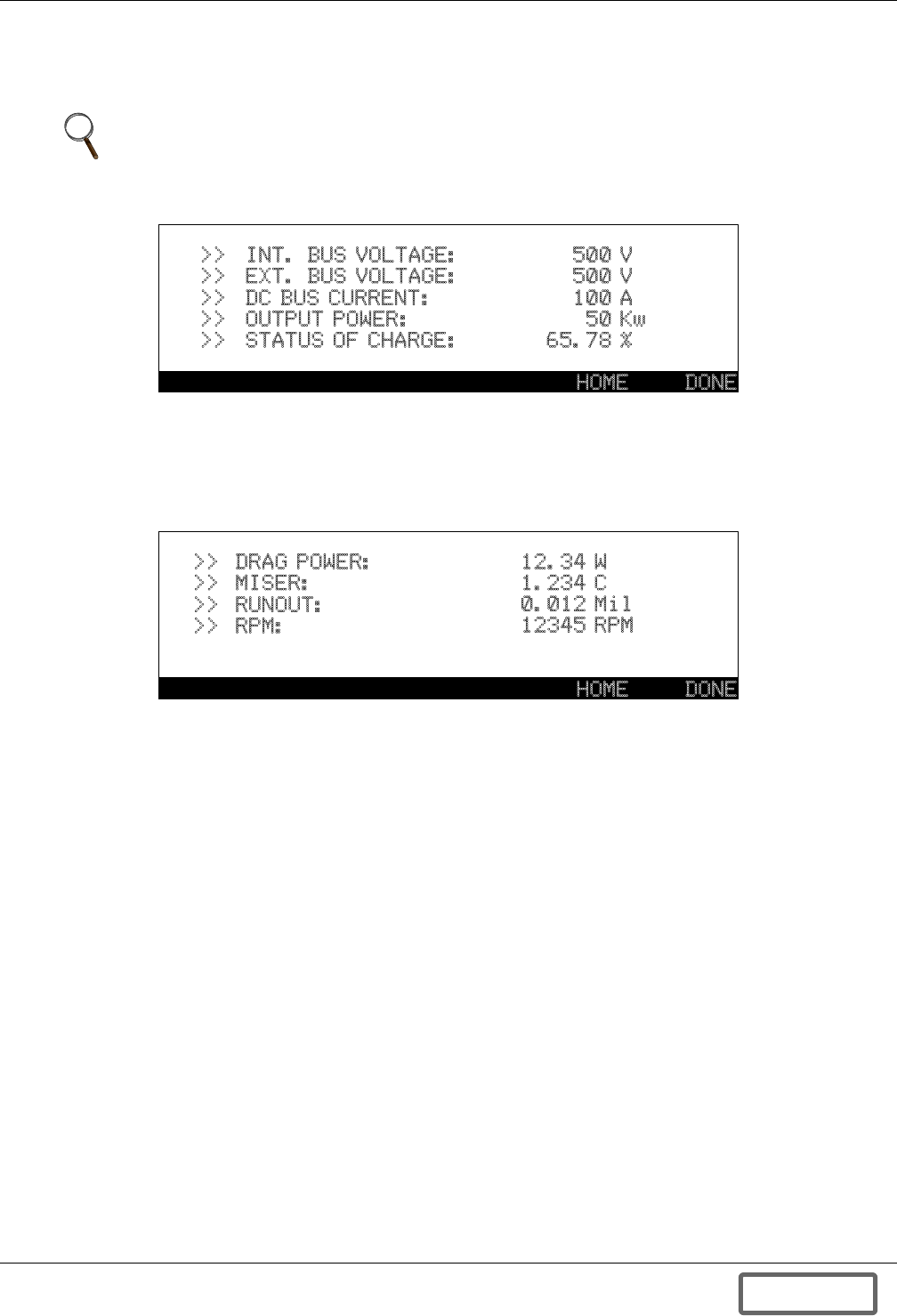
Operation
66
6.4.11 Electrical
The screen MENU>VIEW>ELECTRICAL shows the major electrical system variables. These quanti-
ties are updated continuously.
Figure 81 Electrical view
6.4.12 Vitals
MENU>VIEW>VITALS shows the current vital system values. These quantities are updated continu-
ously.
Figure 82 Vitals view
6.4.13 Security
Security levels can be changed in the MENU>SECURITY screen.
NOTE
Positive values for DC BUS CURRENT and OUTPUT POWER indicate Discharge mode and
negative values for same indicate Charge mode.
HOME DONE
>>
>>
>>
>>
>>
INT. BUS VOLTAGE:
EXT. BUS VOLTAGE:
DC BUS CURRENT:
OUTPUT POWER:
STATUS OF CHARGE:
500
500
100
50
65.78
V
V
A
Kw
%
HOME DONE
>>
>>
>>
>>
DRAG POWER:
MISER:
RUNOUT:
RPM:
12.34
1.234
0.012
12345
W
C
Mil
RPM
DISCONTINUED
PROD UC T
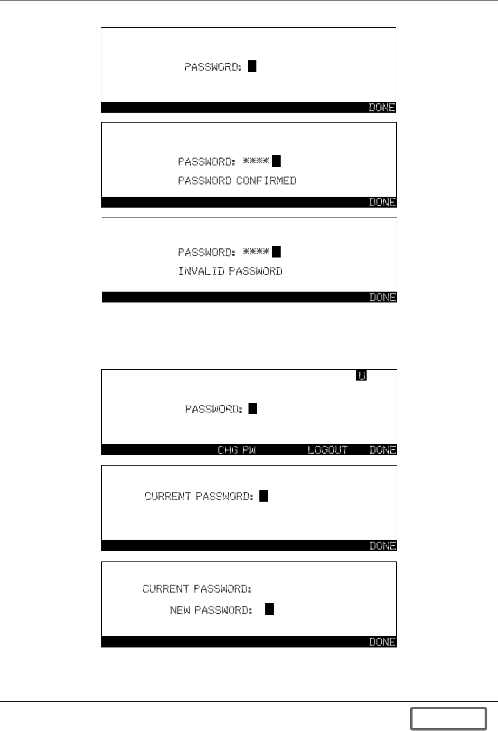
Operation
67
Figure 83 Password screens
USER level password can be modified by pressing the CHG PW button. Current password is required
to change the password. The USER level password should be between 3 - 12 digits length, hence digits
after 13th are ignored if more than 12 digits are entered.
Figure 84 Change password
DONE
PASSWORD:
DONE
PASSWORD: ****
INVALID PASSWORD
DONE
PASSWORD: ****
PASSWORD CONFIRMED
DONE
CURRENT PASSWORD:
DONE
PASSWORD:
LOGOUT
U
CHG PW
DONE
CURRENT PASSWORD:
NEW PASSWORD:
****
DISCONTINUED
PROD UC T
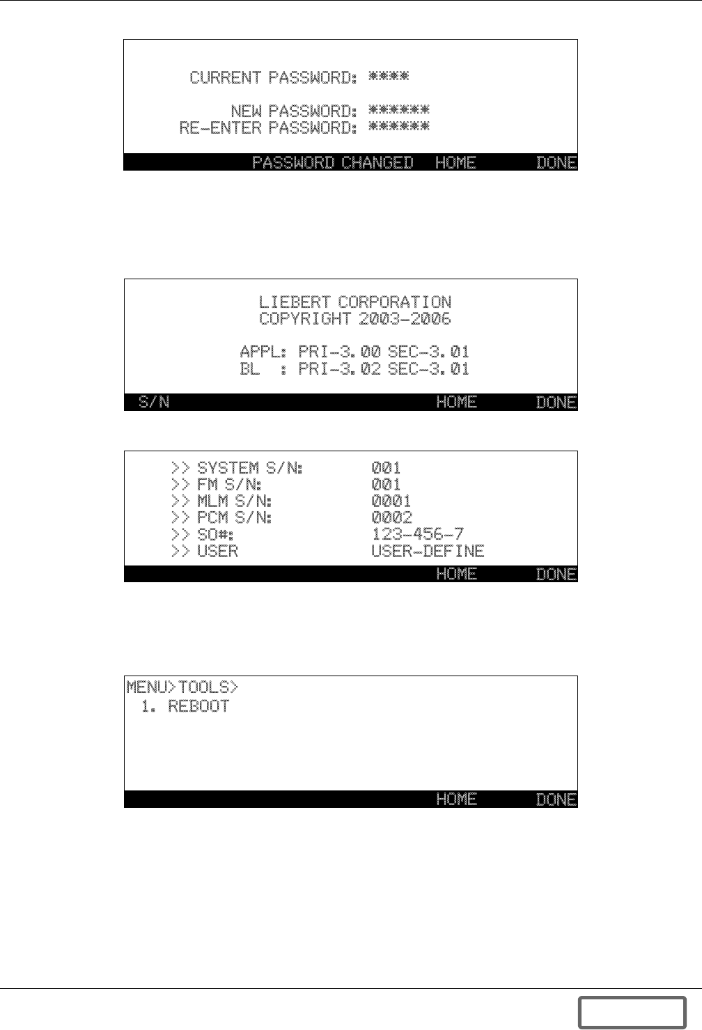
Operation
68
Figure 85 Change password
6.4.14 About
About screen shows the version of the firmware and company information. The controller board has
two DSPs and each DSP has bootloader and application firmware.
Figure 86 ABOUT screen
Figure 87 Serial numbers
6.4.15 Tools
Tools menu has REBOOT function for USER to reboot system.
Figure 88 Tools for USER
DONE
CURRENT PASSWORD:
NEW PASSWORD:
RE-ENTER PASSWORD:
****
******
******
PASSWORD CHANGED HOME
DONE
LIEBERT CORPORATION
COPYRIGHT 2003-2006
APPL: PRI-3.00 SEC-3.01
BL : PRI-3.02 SEC-3.01
S/N HOME
DONE
HOME
>>
>>
>>
>>
>>
>>
SYSTEM S/N:
FM S/N:
MLM S/N:
PCM S/N:
SO#:
USER
001
001
0001
0002
123-456-7
USER-DEFINE
DONE
HOME
MENU>TOOLS>
1. REBOOT
DISCONTINUED
PROD UC T

Operation
69
6.5 System Startup
6.5.1 Initial System Startup Procedure
Initial System Startup is defined as the first or initial startup following installation of the system.
Several additional steps are required prior to the normal startup procedure including the following
Inspection before Initial System Startup, (Section 5.5.2), and Control Parameters Setup (Section
5.5.3.). These steps are required to ensure safe and proper startup of flywheel system and for war-
ranty purposes.
6.5.2 Inspection before Initial System Startup
A Liebert technician will perform the following tasks:
• Visual Inspection
Inspect equipment for signs of damage
Verify installation per drawings
Inspect cabinet for foreign objects
Verify ground conductors are properly sized and connected
Verify all printed circuit boards are configured properly
• Mechanical Inspection
Check all control wiring connections for tightness
Check all power wiring connections for tightness
Check that cabinet is attached to the floor
Check all terminal screws, nuts and/or spade lugs for tightness
Check all cooling pump connections
• Electrical Inspection
Check fuses for continuity
Check and verify UPS DC bus voltage
• Pre-Startup
Perform MLM Pre-Start procedure using Boot Up process with UPS DC bus
Perform MLM Inspection and test
Verify UPS settings and adjustments
Run pumps and fans for several minutes
!CAUTION
The Initial System Startup shall ONLY be performed under the supervision of a
Liebert-certified service technician in order to ensure proper system operation. Failure to
abide by instructions provided herein may void your warranty.
DISCONTINUED
PROD UC T
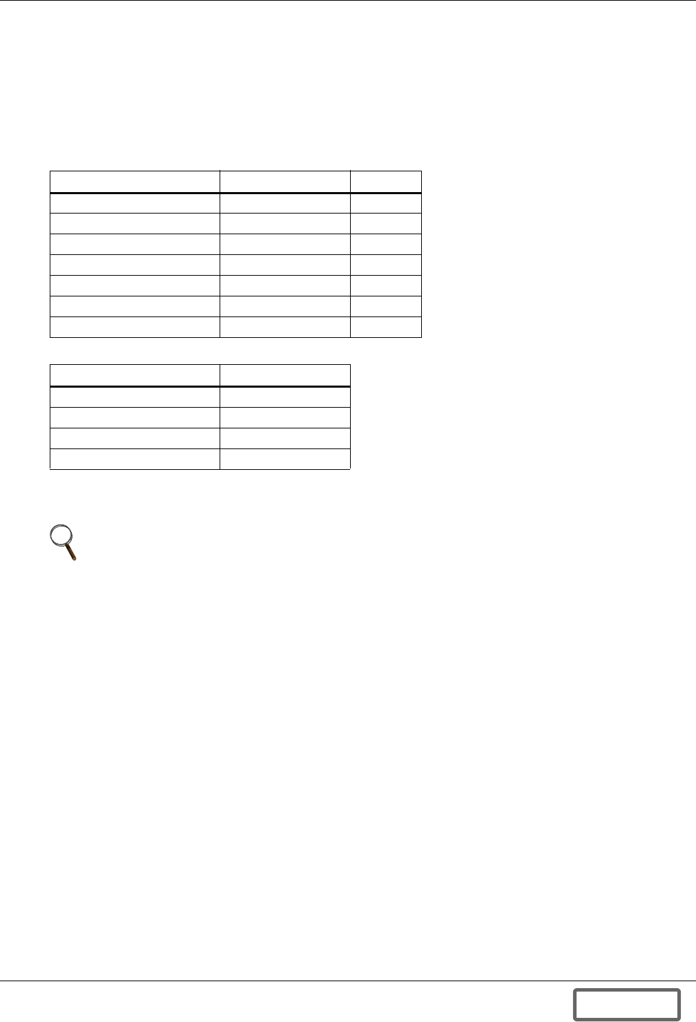
Operation
70
6.5.3 Control Parameters Setup at Initial System Startup
Please have the relevant UPS Interconnection Kit Handbook (Liebert UPS Interconnection Kit [IKIT]
Handbook for specific Brand and Model UPS) available for the Liebert technician. The Control
Parameters Setup values that need to be programmed are included in this manual.
You may record in Table 9 the values found in the specific IKIT (Interconnection Kit) Handbook for
your UPS. For future reference you may also want to record Software Versions; Primary and Second-
ary and Bootloader Version from the About parameter screen, Section 5.4.12. above.
The Liebert technician will perform or direct the Control Parameters Setup (described in 6.4.1 -
Screen Tree Menu Functions) and proceed to the Initial Startup Procedure.
6.5.4 Initial System Startup Procedure
A Liebert technician will perform or direct the following tasks at Initial System Startup:
• Inspection before Initial System Startup (Section 5.5.2. of this manual)
• System Control Parameters Setup
• Assist with Initial System Startup
• Complete Warranty documentation
• Complete commissioning documentation
• Provide basic user training on Liebert FS operation *
Table 9 Control parameters
Control Parameter Value Default
Charge Voltage VDC 530
Regulation Voltage VDC 520
Maximum Charge Current A 30
Charging Amps/Volts A/V 2
Vreg Delta 1 VDC 0
Vreg TSOC % 0
Vreg Delta 2 VDC 0
Table 10 Software versions
Software Application Version
Primary application 2812
Secondary application 6711
Primary Bootloader
Secondary Bootloader
NOTE
DC bus ripple voltage should be measured and taken into consideration when programming
the Charge Voltage; the Charge voltage should be below the DC float voltage and include
compensation for any ripple voltage present to avoid frequent charging and discharging.
DISCONTINUED
PROD UC T
Operation
71
6.5.5 Regular Startup Procedure
6.5.6 Inspection Before Regular Startup
The following verifications must be done before performing a regular startup of the Liebert FS (see
6.5.7 - Starting up the System):
1. Make sure the Liebert FS is properly secured to the floor with the Liebert-provided mounting kit
and in compliance with the floor mounting instructions in 4.1 - Cabinet Floor Mounting.
2. Check for coolant leaks in and around the Liebert FS unit.
3. Ensure that Liebert FS cabinet panels are in place on the cabinet and that no tools have been left
in the cabinet
4. Ensure that the Liebert FS Main circuit-breaker (optional) or the customer-provided external DC
disconnect switch is open
5. Verify that the AC Auxiliary Backup Power is connected and powered by closing fused disconnect
or wall disconnect and check if the Control Panel is ON and with no warning or fault messages
displayed.
The Liebert FS may now be started up.
6.5.7 Starting up the System
Powering Up the Liebert FS
Once AC voltage is applied to the Liebert FS, the Liebert FS Control Panel will boot up. Its screen will
begin to illuminate after 5 to 10 seconds and then display a series of boot up protocols.
Booting Up
1. It takes about 25 seconds to load and initialize the primary application software at STARTUP or
after reset.
2. Title block and firmware versions will be displayed (see Figure 82). If the secondary DSP does
not boot up properly, versions for the secondary DSP may be corrupted or zero.
3. EEPROM checksum will be calculated and compared with the stored value. EEPROM checksum
fault will be generated if they do not match. For this case, default values are loaded for
parameters in RAM. However, EEPROM contents are not changed.
4. Response from secondary DSP will be checked. “INTERPROCESSOR COMM FAULT” will be
generated if the communication is not set up properly. The controller will reset itself for this case.
5. Previous operation command (STARTUP or SHUTDOWN) will be retrieved to determine the
current operation mode.
6. Option status is checked. Current available options are VIB and DCM.
!CAUTION
The Initial System Startup shall be performed ONLY under the supervision of a Liebert
technician to ensure proper system operation. Failure to abide by instructions provided herein
may void your warranty.
NOTE
A regular startup is any startup after the Initial System Startup.
!CAUTION
The following procedure assumes that the Initial System Startup has been performed under
the supervision of a Liebert technician.
!CAUTION
Do not attempt to run the system unless the system loads valid parameters.
DISCONTINUED
PROD UC T

Operation
72
Validation of Control Parameters Setup
1. Once the Control Panel has successfully booted up, the Control Panel will display the Main
Screen (see Figure 55).
2. Verify the Control Parameters values are correct. (Consult Table 9 and the relevant UPS
Interconnection Kit Handbook for choosing the proper Control Parameters values).
3. Adjust the Control Parameters values if necessary (see 6.4.1 - Screen Tree Menu Functions).
for instruction on how to change the values of the Control Parameters) then press “F6 DONE”.
Initiating Liebert FS Startup Sequence
1. Once sufficient DC voltage is applied to the UPS DC Bus, the Liebert FS will be able to transition
from the OFF Mode to Startup Mode, unless system was previously Shutdown by command.
The following action is conditional on the UPS interconnection kit that has been installed on your
Liebert FS:
•Standard UPS Interconnection Kit (IKIT-STD)
The Standard UPS interconnection kit (IKIT-STD) includes a fused Power Terminal Block. It is
recommended for maintenance use to have an external disconnect switch installed between the
UPS and the Liebert FS.
Close the customer-provided external disconnect switch at the time indicated by the UPS startup
procedure.
•Optional UPS Interconnection Kit
Open the Liebert FS cabinet front door and close the Liebert FS main circuit-breaker at the time
indicated by the UPS startup procedure. Close the cabinet door.
2. The Control Panel will then show the Main screen (see Figure 55). The System Mode should read
“OFF”. The Liebert FS will actively check for presence of sufficient voltage to allow system
startup.
3. As soon as the UPS DC bus voltage is greater than Vcharge, the System Status will change from
“OFF” to “STAND BY”. The “F1 STARTUP” key will then be enabled.
4. Press the “F1 STARTUP” key.
Liebert FS Startup Sequence
As soon as the “F1 STARTUP” key is pressed, the Liebert FS will launch its startup sequence. This
will progressively lead the Liebert FS through the different Modes of Operation (STAND BY, STAR-
TUP, CHARGE) to eventually reach a ready state of idling (READY Mode) once it is completely
charged up. The automatic transition between modes is described in 5.2 - List of System User-Con-
figurable Parameters.
6.6 Shutdown Procedure
There are two ways the Liebert FS may enter a Shutdown sequence: either a) following a Liebert FS
discharge down to SOC = 0%; or b) following a user-initiated command.
In any Mode, except OFF Mode, the user may command the Liebert FS to transition in SHUTDOWN
Mode by pressing the “F2 SHUTDOWN” key. This action is recommended for normal shutdown of the
system. In this condition, the Liebert FS will not discharge to support an outage. You will be asked to
confirm “Yes” or “No” to SHUTDOWN. Press “Yes” to confirm shutdown and put system in SHUT-
DOWN mode.
For more information concerning the SHUTDOWN Mode, please refer to 5.2 - List of System User-
Configurable Parameters.
NOTE
Startup procedures will vary for each UPS model.
NOTE
Optional UPS interconnection kits include circuit-breakers then referred to as “Liebert FS
Main circuit-breaker”.
DISCONTINUED
PROD UC T
Maintenance
73
7.0 MAINTENANCE
7.1 Safety Precautions
Observe all safety precautions in this manual, paying particular attention to Important Safety
Instructions on page 1.
ONLY qualified service personnel should perform maintenance on the Liebert FS.
Observe all of the warnings below before performing any maintenance on the Liebert FS and associ-
ated equipment.
!WARNING
Before performing preventive maintenance tasks, the Liebert FS must be de-energized and
electrically isolated (both AC and DC connections to the Liebert FS must be electrically
disconnected).
!CAUTION
Always identify connecting wiring prior to disconnecting any wiring.
Do not substitute parts except as authorized by Liebert Corporation.
Keep Liebert FS cabinets free of foreign materials such as solder, wire cuttings, etc.
Contact Liebert Services if you are not sure of the procedures to follow or if you are not
familiar with the circuitry.
!WARNING
Extreme caution is required when performing maintenance.
Be constantly aware that the Liebert FS contains high DC as well as AC voltages. With input
power off and the battery disconnected, high voltage at filter capacitors and power circuits
should be discharged within 30 seconds. However, if a power circuit failure has occurred, you
should assume that high voltage may still exist after shutdown. Check with a voltmeter
before making contact.
Check for voltage with both AC and DC voltmeters prior to making contact.
When the Liebert FS is under power, both the operator and any test equipment must be
isolated from direct contact with earth ground and the chassis frame by using rubber mats.
Some components within the cabinet are not connected to chassis ground.
Any contact between floating circuits and the chassis is a lethal shock hazard. Use differential
oscilloscopes when measuring a floating circuit. The differential input should have at least
800 VRMS common mode input rating and a common mode rejection ratio of at least 80dB.
Exercise caution that the test instrument exterior does not make contact, either physically or
electrically, with earth ground.
In case of fire involving electrical equipment, use only carbon dioxide fire extinguishers or
others approved for use in fighting electrical fires.
DISCONTINUED
PROD UC T

Maintenance
74
7.2 Liebert Services
Startup, maintenance and training programs for the Liebert FS are available through your Liebert
sales representative.
Professional Startup
Liebert FS Startup—Liebert’s customer engineers perform a thorough, non-powered inspection of
the units and will then conduct a complete electrical checkout that includes calibrating all compo-
nents to published specifications. Customer operation training will be conducted during startup.
Load bank testing and full site acceptance testing are additional services that can be performed dur-
ing a Liebert FS startup. One preventive maintenance service call can be added to the initial
Liebert FS startup agreement.
Maintenance Agreements: The Signature Program
Liebert FS Service Agreements—Liebert Services has a variety of available maintenance agree-
ments, depending on specific site needs. Choose the level of support appropriate for each installation.
Mission-critical sites can have the standard parts-and-labor, around-the-clock coverage for their
Liebert FS, with or without scheduled preventive maintenance visits. Other sites can benefit from a
variety of money-saving options.
While the Liebert FS is designed to be maintenance-free, Liebert suggests at least one preventive
maintenance visit per year. This preventive maintenance work would normally be done in conjunction
with a service visit for another Liebert UPS product. The annual visit will require taking the
Liebert FS off-line for a thorough, nonpowered inspection. These visits are in addition to the general
housekeeping tasks (changing air filters, etc.) that can be performed by customer personnel.
Training
Customer training courses include the proper operation of the system, emergency procedures, preven-
tive maintenance and some corrective maintenance.
Warranties
Contact Liebert Services if you have any questions regarding the warranty on your Liebert FS.
7.3 Routine Maintenance
You are encouraged to become thoroughly familiar with the equipment, but at no time should you go
beyond the specific procedures in this manual while performing maintenance or correcting a malfunc-
tion. If you have any doubt as to what must be done, call Liebert Services at 1-800-LIEBERT for fur-
ther instructions.
The Liebert FS is designed for unattended operation, but does require some common-sense mainte-
nance:
• Keep good records—Troubleshooting is easier if you have historical background
• Keep it clean—Keep the Liebert FS free of dust and moisture
• Keep it cool—The Liebert FS will reliably meet all performance specifications and design life at
temperatures up to 122°F (50°C)
• Keep connections tight—Tighten all connections at installation and at least annually thereafter
(see torque requirements,Table 12)
DISCONTINUED
PROD UC T
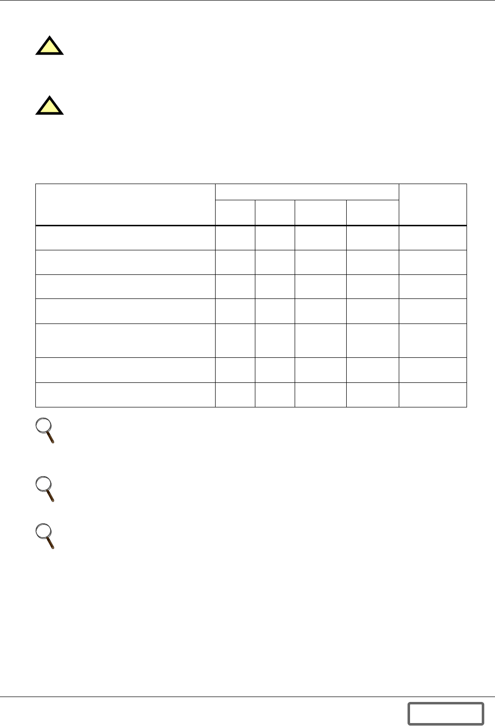
Maintenance
75
7.4 Maintenance Schedule
The Liebert FS maintenance schedule consists of actions listed in Table 11.
7.5 Record Log
Set up a maintenance log to record scheduled checks and any abnormal conditions.
The log should have space for all metered parameter indications including phase readings, alarm
messages, mode of operation, air filter replacement date and observation notes.
A periodic walk-through inspection of the Liebert FS room is advised to check for visible and audible
indications of problems. Log the inspection, metered parameter indications and any discrepancies.
!WARNING
Any maintenance on the system should be delayed by at least 10 minutes after system is shut
down to be certain all electronics have discharged. Use appropriate safety precautions to
ensure unit is disconnected and de-energized.
!CAUTION
Unless specified otherwise, ONLY a Liebert-certified service technician should perform all
maintenance work. Failure to use a Liebert technician for maintenance actions, unless
specifically noted, may void your warranty.
Table 11 Maintenance schedule
Item/Action
Frequency
Service
Performer
Every
1 yr
Every
2 yrs
Every
6 yrs
Every
15 yrs
System Visual Inspection * Check
or Test — — — Liebert/Owner
System Cleaning (if necessary) Check
or Test — — — Liebert/Owner
System Testing
(and adjustments, if necessary) —Check
or Test — — Liebert
PCM Capacitor Bank — — Service or
Replace — Liebert
Flywheel Module
Once
after
Startup
Check
or Test —Service or
Replace Liebert
UPS Interconnection Kit (if option installed) — Check
or Test — — Liebert
Air Filter (if option installed) Check
or Test — — — Liebert/Owner
NOTE
The recommended System Visual Inspection every year should include a check and torque of
cabinet DC circuit breaker box lug connections and the DC ground; see the relevant section of
Appendix A.0 - UPS Interconnection Kits for torque requirements.
NOTE
Liebert may determine additional maintenance actions as necessary and issue service or
technical bulletins to address any additions.
NOTE
The optional inlet Air Filter in the cabinet will need to be replaced when it is sufficiently dirty
to significantly reduce the flow of air into the cabinet. Ambient conditions at the installation
site will determine the frequency of replacement if option is installed
DISCONTINUED
PROD UC T
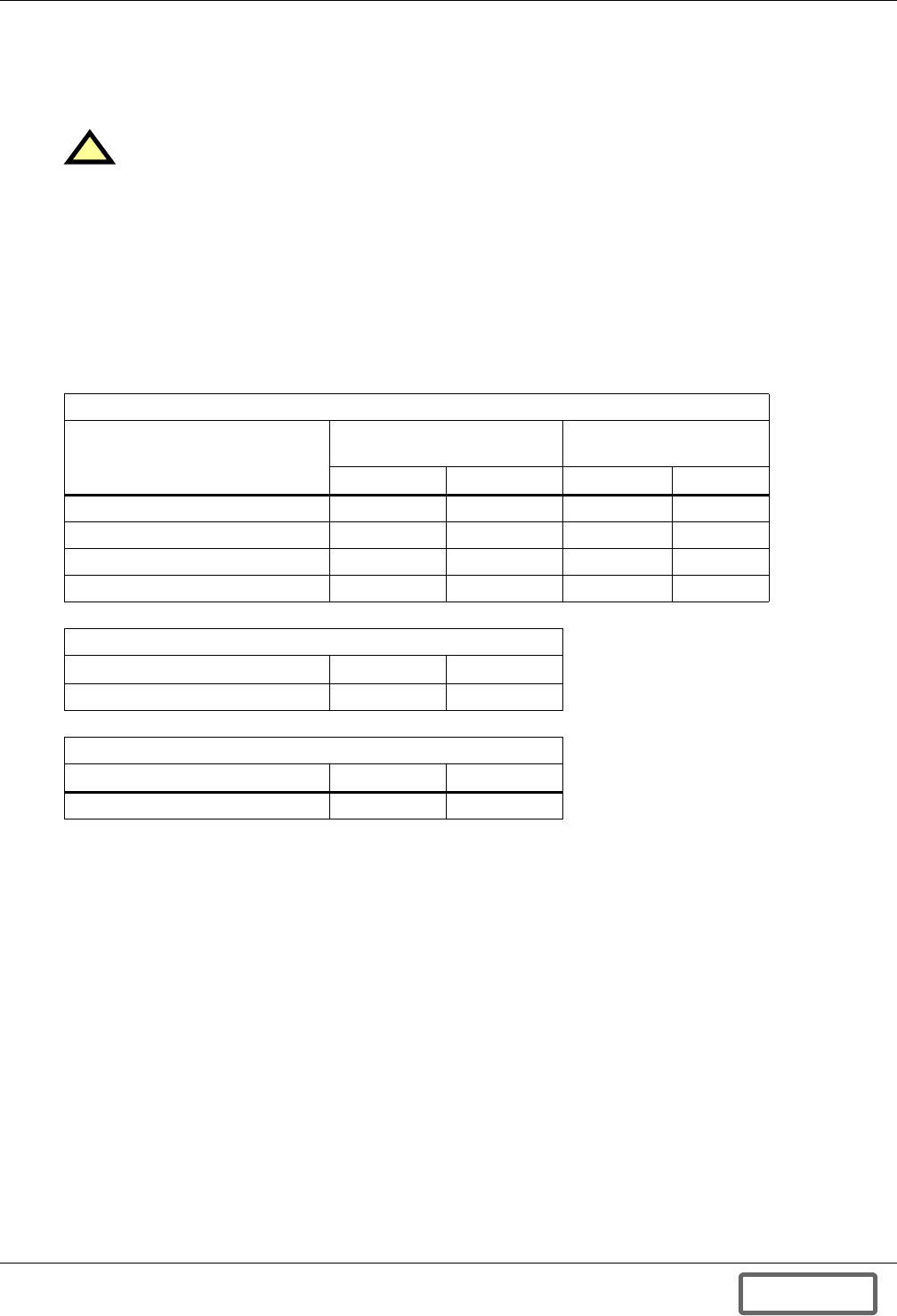
Maintenance
76
7.6 Optional Air Filters
The optional air filters must be inspected and serviced on a regular schedule. The period between
inspections will depend upon environmental conditions. Under normal conditions, the air filters will
require cleaning or replacement approximately every 12 months.
Abnormal or dusty conditions will require more-frequent cleaning and replacement of air filters
(sometimes as often as every two months). Inspect installations in new buildings more often, then
extend the inspection period as experience dictates.
7.7 Torque Requirements
All electrical connections must be tight. Table 12 provides the torque values for the connections in
the Liebert FS. Use these values unless the equipment is labeled otherwise.
7.8 Detecting Trouble
It is important that the operator check the instrument readings if abnormal equipment performance
is suspected. Any metered value that differs appreciably from normal could mean an impending mal-
function and should be investigated.
Items to check include:
• Alarm messages indicate malfunction or impending malfunction. A daily check of the operator
control panel will help to provide an early detection of problems. Refer to Table 16 to interpret
alarm messages.
• Tracing a problem to a particular section is facilitated by alarm messages and the metered
parameter indications. These are stored in the Status Reports and can be displayed at the opera-
tor control panel or at an optional terminal. A Liebert Services engineer will be familiar with test
points inside the unit.
!CAUTION
Be certain recyclable filter elements are dry before reinstalling them in the Liebert FS.
Table 12 Torque specifications (unless otherwise labeled)
Nut And Bolt Combinations
Bolt Shaft Size
Grade 2
Standard
Electrical Connections
With Belleville Washers
Lb-in N-m Lb-in N-m
1/4 53 6.0 46 5.2
5/16 107 12 60 6.8
3/8 192 22 95 11
1/2 428 48 256 29
Circuit Breakers with Compression Lugs (For Power Wiring)
Current Rating Lb-in N-m
250A 250 28
Circuit Breakers with Compression Lugs (For Control Wiring)
AWG Wire Size or Range Lb-in N-m
#22 - #14 3.5 to 5.3 0.4 to 0.6
DISCONTINUED
PROD UC T
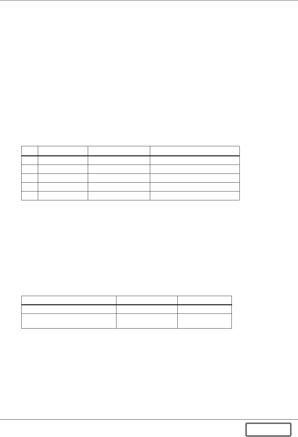
Maintenance
77
7.9 Reporting a Problem
If a problem occurs within the Liebert FS, review all alarm messages along with other pertinent data.
This information should be given by telephone to the Liebert service representative’s office nearest
you. This information can be downloaded to Liebert Services by using the optional modem. Contact
Liebert Services at 1-800-LIEBERT to report a problem or to request assistance.
7.10 Corrective Actions
For each alarm message on the operator control panel, you can find the recommended corrective
action in Table 16.
7.11 Recommended Test Equipment
Table 13 lists recommended test equipment and tools required to maintain, troubleshoot and repair
the Liebert FS. You may substitute instruments of equivalent range and accuracy.
All instruments should be calibrated and be within the current calibration cycle. Calibration data for
the instruments should be maintained in equipment-history files and the instruments labeled for
audit and verification.
7.12 Limited Life Components
Your Liebert FS has a design life well in excess of 15 years. Well-maintained units can continue to
provide economic benefits for 20 years or more. Long-life components are used in your Liebert FS
wherever practical and cost-effective.
However, due to current component material and manufacturing technology limitations, a few compo-
nents in your Liebert FS will wear out and require replacement in less than 10 years. The following
limited-life components are utilized in your Liebert FS. In order to prevent a wear-out failure of one of
these components affecting your critical load operations, it is recommended these components be peri-
odically inspected and replaced before their expected wear-out life. Individual users may have site-
specific requirements that differ from these typical life expectations.
Power capacitors are considered “failed” when their measured capacitance is –5% below their name-
plate rating.
In most cases, replacement components must exactly match the original component specifications and
are not readily available from third-party component distributors. For assistance with your specific
component specifications, replacement component selection and sourcing, call 1-800-Liebert.
For customers using Liebert Services’ Preventive Maintenance Services, periodic inspection of these
components are part of this service as is recommending to customers replacement intervals to avoid
interruptions in critical load operations.
Table 13 Recommended test equipment and tools
Qty Test Equipment Manufacturer Model or Type
1 Oscilloscope Tektronix, H-P or Fluke DC to 50 MHz
2 Voltage Probes Tektronix, H-P or Fluke 10X, with 10 ft cable
2 Voltage Probes Tektronix, H-P or Fluke 100X, with 10 ft cable
1 Digital Multi-meter Fluke 87, with test leads
1 Tool Kit N/A Standard electrical contractor tools
Table 14 Projected component life, replacement schedule
Component Expected Life Replace in:
Power DC filter capacitors About 7 years 5-6 years
Air filters, disposable
(see also 7.6 - Optional Air Filters) 1-3 years Check 4 times/year
DISCONTINUED
PROD UC T
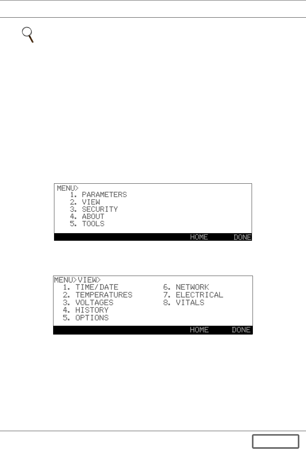
Troubleshooting
78
8.0 TROUBLESHOOTING
8.1 General
The Liebert FS is capable of detecting conditions outside of normal operating parameters and provid-
ing notice at the Control Panel. This data is recorded as either Warnings or Faults and can be viewed
in the software menu tree at the screen location MENU>VIEW>. These Warnings and Faults can also
be communicated by the Versatile Interface Board (VIB), if this option has been installed, to an exter-
nal device or system; (see Appendix C.0 - Versatile Interface Board). This data will also be
recorded in the Data Collection Module option if this has been selected. Please see Appendix B.0 -
Data Collection Module for instructions on how to access this data via the DCM.
Any Warnings and Faults that may occur will be displayed on the Main screen of the Control Panel.
The Liebert FS’ Warnings and Faults tables (see Tables 15 and 16), describe these Warnings, mean-
ings and possible causes. The operator action required or automatic system function that will result is
explained.
In addition to the information displayed on the Main screen, other system information that can be
used for troubleshooting is available and can be accessed from the Control Panel. From the Main
screen the Menu screen can be selected by pressing (F6) on the Control Panel located below MENU.
Figure 89 USER level menu
Selecting View displays various system statuses including real-time and historical data. You can
select the function by number.
Figure 90 VIEW menu
Selecting History will provide a history of Warnings and Faults as introduced in Section 5, Opera-
tions, of this manual. Other information that can be useful in troubleshooting are the Temperatures,
Voltages, Options, Electrical and Vitals screens.
Warning/Fault: The Liebert FS holds 35 warning and fault information, respectively. A single screen
shows seven warnings or faults. Users can move between pages using PREV, NEXT button. (See
Figures 91 and 92 below).
NOTE
Refer to this section before calling Liebert Services for support.
DONE
HOME
MENU>
1. PARAMETERS
2. VIEW
3. SECURITY
4. ABOUT
5. TOOLS
1. TIME/DATE
2. TEMPERATURES
3. VOLTAGES
4. HISTORY
5. OPTIONS
6. NETWORK
7. ELECTRICAL
8. VITALS
MENU>VIEW>
HOME DONE
DISCONTINUED
PROD UC T
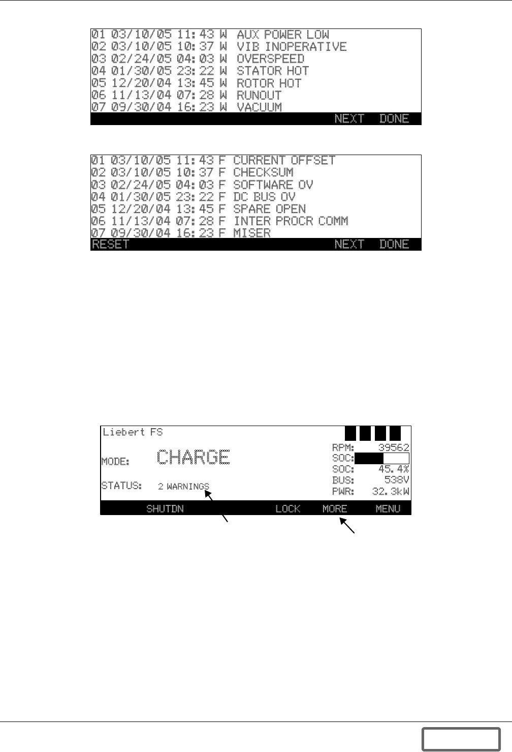
Troubleshooting
79
Figure 91 Warning history
Figure 92 Fault history
The warnings, fault meanings and possible causes in the following text and in Table 15 may be used
in troubleshooting the messages and may also aid in identifying conditions outside the flywheel sys-
tem that may adversely affect it.
8.2 Warnings
A Warning is an indication of an abnormal system condition significant enough to warrant being
annunciated and logged. Warning conditions may indicate that a system parameter is out of its nor-
mal operating range, or may signal an external problem. A Warning indication is for information only
and does not require any operator intervention for continued operation of the unit. While in Warning
condition, normal operation of the unit will continue unimpeded. A warning can indicate an operating
condition that warrants observation and may require preventative maintenance.
Figure 93 Warning screen
The Warning condition is indicated by the System Status field displaying “WARNING” in the Control
Panel window (see Figure 93). If one Warning is present, the Warning Label (see Table 15.) will be
displayed.
While the Warning condition exists, and if more than one Warning is present, F5 the “More Info” key
will be enabled in the Control Panel window. If pressed, the separate Warning Labels will be dis-
played in the Control Panel window.
Any of eight warnings could occur while the Liebert FS is operating. Warnings give advance alert of
potential problems and schedule service and preventive maintenance. These can be monitored and
investigated through the use of data from the Control Panel and system tests.
NEXT DONE
01 03/10/05 11:43 W
02 03/10/05 10:37 W
03 02/24/05 04:03 W
04 01/30/05 23:22 W
05 12/20/04 13:45 W
06 11/13/04 07:28 W
07 09/30/04 16:23 W
AUX POWER LOW
VIB INOPERATIVE
OVERSPEED
STATOR HOT
ROTOR HOT
RUNOUT
VACUUM
NEXT DONE
01 03/10/05 11:43 F
02 03/10/05 10:37 F
03 02/24/05 04:03 F
04 01/30/05 23:22 F
05 12/20/04 13:45 F
06 11/13/04 07:28 F
07 09/30/04 16:23 F
CURRENT OFFSET
CHECKSUM
SOFTWARE OV
DC BUS OV
SPARE OPEN
INTER PROCR COMM
MISER
RESET
MODE:
STATUS:
D V U C
RPM:
SOC:
SOC:
BUS:
PWR:
39562
45.4%
538V
32.3kW
CHARGE
2 WARNINGS
SHUTDN MORE MENU
Liebert FS
LOCK
More information
Button (F5)
Warning Status Message
DISCONTINUED
PROD UC T
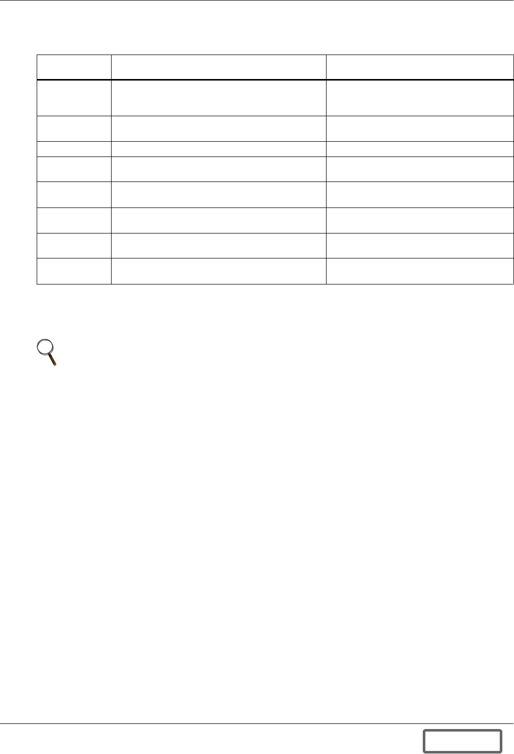
Troubleshooting
80
Table 15 lists the warnings and some troubleshooting steps that may be taken if any of the Warnings
in appear.
If Warnings persist, contact your local Liebert representative or contact Liebert Services at 800-543-
2378. You may also visit the Liebert Web site for information at www.liebert.com.
Table 15 Warnings
Warning
Label Meaning / Possible Causes Troubleshooting
AUXPOWER
LOW
Auxiliary power supply is low when the system is
not in OFF mode.
Factory-configurable warning
Check / Test Auxiliary power supply
VACUUM
LOW Drag power exceeds 85W *Check Vitals and Vacuum History
MISER HIGH Miser voltage is higher than 2V Calibrate board
RUNOUT
HIGH Runout is higher than 2.0 mil.*Check Vitals and Runout History
PWR SPLY
VOLT LOW Power supply for PPMC/PCMC is lower than 21V. Power supply for PPMC/PCMC is lower
than 21V
VIB
INOPERATIVE VIB inoperative while enabled Check VIB cable connections and wiring
OVERSPEED Speed is higher than the Max Speed Have Certified Service personnel check
software settings
SET TIME/
DATE Time and date have not been set Set Time/Date in Menu>View>Time/Date
* Warnings of this nature should be monitored and may be used to schedule preventive maintenance.
NOTE
A “Standby, Motor Hot” message may be displayed as a result of consecutive and repetitive
discharges. This is not a Warning but a normal operating occurrence that may occur due to
frequent charging and discharging of system. Once motor cools it will automatically resume
operation.
DISCONTINUED
PROD UC T
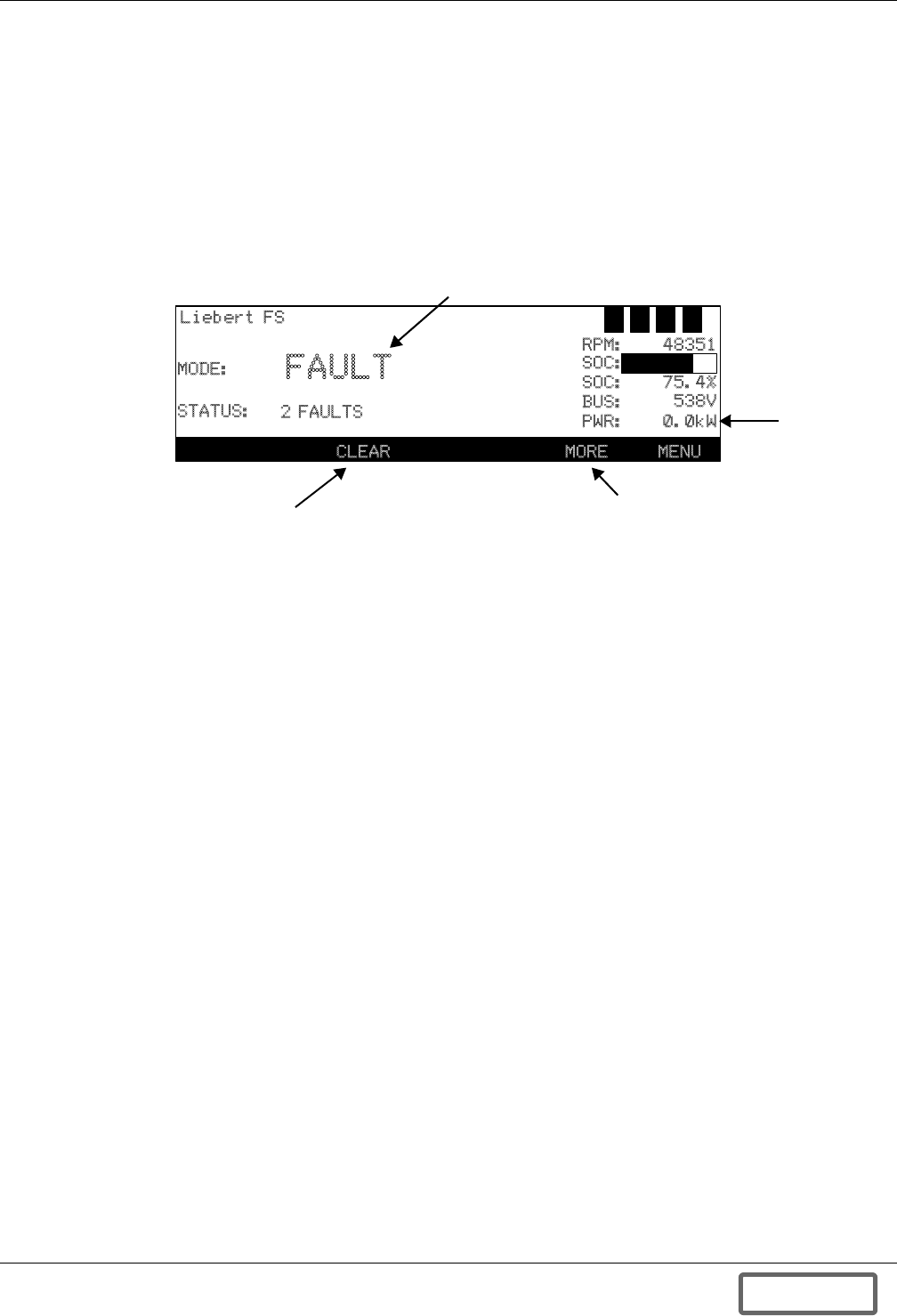
Troubleshooting
81
8.3 Faults
A Fault is defined as an undesirable system operating condition that could cause further damage to
the system or potentially drop the load. Once detected, Faults may trigger an appropriate emergency
action such as shutting the unit down. Most Fault conditions are automatically taken care of by the
Liebert FS control system and require no Operator intervention. A few Fault conditions may be
resolved only through operator intervention or service by a Liebert technician.
A Fault condition must be valid for a certain amount of time before it is recognized as an active Fault.
This prevents spurious signals from causing false Fault detection and unnecessary state changes.
Figure 93 shows the appearance of an active Fault on the main screen.
Figure 94 Fault screen descriptions
While in Fault condition, normal operation of the unit is suspended, the operation of the Power Con-
version Module is paused, and the unit transitions into FAULT Mode, where it waits for one of the fol-
lowing to occur:
1. The condition to clear the fault [AUTO CLEAR]
2. The unit to automatically transition in SHUTDOWN Mode [AUTO SHUTDOWN]
3. Operator action [OPERATOR CLEAR].
The Fault condition is indicated by the System Mode displaying “FAULT” in the Control Panel win-
dow.
If there are multiple Fault conditions present, the F5 “More Info” key will be enabled in the Control
Panel window. If pressed, information related to the specific Faults will be displayed in the Control
Panel window (see Figures 54 through 56). If there are multiple faults they will both be displayed by
pressing the F5 “MORE” button.
In many cases, when FAULT Mode is entered, the Fault may be cleared by pressing the F3 “CLEAR
FAULT” button on the Control Panel or utilizing the VIB option - if enabled - to send a “CLEAR
FAULT” signal to the system. In order to “CLEAR FAULT” the operator must be in proper security
access level; User or above. Table 16 describes the fault labels, meanings and possible causes for the
MODE:
STATUS:
D V U C
RPM:
SOC:
SOC:
BUS:
PWR:
48351
75.4%
538V
0.0kW
FAULT
2 FAULTS
CLEAR MORE MENU
Liebert FS
More information
Button (F5)
Fault Status Message
Fault Clear Button (F3)
Bus Power
DISCONTINUED
PROD UC T

Troubleshooting
82
Faults. Table 17 - Troubleshooting describes actions that may alleviate the condition or provide
valuable information for technical support.
Faults that initiate an AUTOSHUTDOWN include: MISER, RUNOUT, PWR SPLY VOLT (at high
speed), and will require Service level and higher to reset.
Table 16 Faults—causes and responses
Fault Label Meaning / Possible Causes
Operator
Clear*
Auto
Clear
Auto
Shutdown
GROUND FAULT Ground fault current out of range. X
HW BUS OV HW overvoltage. (hardware protection) X
X PHASE OC AC phase overcurrent. x = A, B, C. X
IGBT OVRTEMP IGBT overtemperature. X
VACUUM FAULT Drag power exceeds 125W. X
RUNOUT FAULT Runout higher than 2.9mil. X
MISER FAULT Miser voltage is higher than 5V. X
BEARING Magnetic bearing fault. X
AUX POWER LOW Auxiliary power supply voltage is low when the
system is in Off mode. Configurable fault. X
INTER PRCR COMM Communication error with secondary DSP. System
reboots. X
PWR SPLY VOLT Power supply voltage is lower than 19V. (Speed
dependent; auto shutdown at high speed) XX
UNDEF PDP INT Undefined PDP interrupt. X
CURRENT OFFSET AC motor current sensor error. X
SW OV DC bus voltage is higher than the threshold, which is
service-configurable. X
CHECKSUM Calculated checksum does not match the stored
checksum. S
CONTACTOR TIME OUT Bus voltage/current is not stable while trying to close
or open contactor. X
CONTACTOR CLOSE FAIL Contactor failed to close on startup. X
FAN OPEN Fan open circuit or disconnected. X
FAN SHORT Fan short circuit. X
PUMP OPEN Pump open circuit or disconnected. X
PUMP SHORT Pump short circuit. X
HW OVERSPEED Hardware detected overspeed. X
PRECHARGE PROTECTION Stop PWM when large voltage differential exists
between internal and external bus. X
BUS CURRENT OFFSET DC current sensor error. X
S - Indicates a Certified Service Provider will be required to reset system.
NOTE
If a fault recurs after being cleared by the operator, and the condition persists, contact your
Liebert technician.
DISCONTINUED
PROD UC T

Troubleshooting
83
Fault messages displayed can, in some cases, be investigated for a solution. Listed below in Table 17
are troubleshooting steps for the Fault messages that can occur.
Refer to the general drawings in Appendix D.0 - Installation Drawings for the location of system
components.
If a Fault condition persists contact your Liebert technician. You may also visit the Liebert Web site
at www.liebert.com for information.
Table 17 Troubleshooting
Fault Label Troubleshooting Action
GROUND FAULT Contact Service provider. Schedule service.
HW BUS OV Check DC bus voltage at UPS and adjust as necessary to within threshold.
X PHASE OC Check IGBT, resistor diodes.
IGBT OVRTEMP Check cooling pump, test pump and fans.
VACUUM FAULT Check in History, Vitals, collect data, contact Certified Service Provider.
RUNOUT FAULT Check in History, Vitals, collect data, contact Certified Service Provider.
MISER FAULT Check calibration in Tools.
BEARING Contact Service provider. Schedule service.
AUX POWER LOW Check and test Auxiliary Power module.
INTER PRCR COMM Contact Service provider. Schedule service.
PWR SPLY VOLT Check data in Menu>View>Electrical.
UNDEF PDP INT Contact Service provider. Schedule service.
CURRENT OFFSET Contact Service provider. Schedule service.
SW OV Contact Service provider. Schedule service.
CHECKSUM Contact Service provider. Schedule service.
CONTACTOR TIME OUT Check DC bus voltage at UPS and adjust as necessary to within threshold.
CONTACTOR CLOSE FAIL Check DC bus voltage at UPS and adjust as necessary to within threshold.
FAN OPEN Check fan connections.
FAN SHORT Check fan.
PUMP OPEN Check pump connections.
PUMP SHORT Check pump.
HW OVERSPEED Contact Service provider. Schedule service.
PRECHARGE PROTECTION Contact Service provider. Schedule service.
BUS CURRENT OFFSET Check bus voltages, contact service provider to calibrate settings.
DISCONTINUED
PROD UC T
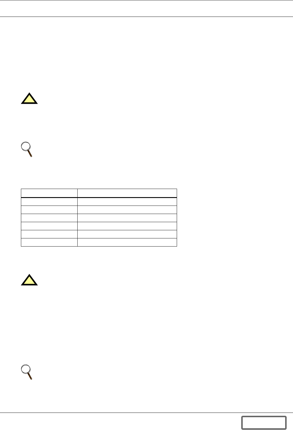
UPS Interconnection Kits
84
APPENDIX A.0UPS INTERCONNECTION KITS
Your Liebert FS is equipped with a UPS interconnection kit to connect it to one of these Liebert UPS
systems:
• Liebert Series 610™, 600T™ or 600™
• Liebert Npower™
• Liebert Series 300™
• Liebert HiPulse™
The Liebert FS system must be installed according to the instructions in 4.0 - Installation. Integrate
your Liebert FS system into an Uninterruptible Power Supply (UPS) system in accordance with the
instructions and drawings in this manual.
Appendix A.1 Wiring Connections
Appendix A.1.1 General Wiring Considerations
The electrical connections to the Liebert FS are:
• DC power
• Status/control
• Ground
• Auxiliary backup power
• Remote monitoring (optional)
!CAUTION
The initial system startup must be performed ONLY under the supervision of a
Liebert-certified service technician to ensure proper system operation. Failure to abide by
instructions provided herein may void your warranty.
Contact your local Liebert sales representative or Liebert Services at 1-800-LIEBERT to
arrange for system startup.
NOTE
Before beginning installation, ensure that your Liebert FS unit is equipped with the correct
UPS interconnection kit.
The first two digits of the Liebert FS model number represent the UPS system the product is
designed for, as shown in Table 18.
Table 18 Key to UPS model interconnection
Liebert FS Model # Use With Liebert UPS
25FS Liebert Series 300
37FS Liebert Npower
39FS Liebert Series 610/600T/600
Contact Liebert Liebert NXL
Contact Liebert Liebert NX
Contact Liebert Liebert HiPulse (50Hz European Model)
!CAUTION
A qualified electrical contractor must perform all electrical connections. The wires (DC power,
ground, optional status/control and auxiliary backup power) that connect the Liebert FS
system(s) to the UPS system are field-supplied or, as an option, by Liebert. Wire size and
installation must comply with all applicable local, regional and national regulations (e.g.,
National Electric Code for USA).
NOTE
The connection instructions included in this section address ONLY the cabling of the DC power
and Status/Control connections specific to the individual UPS interconnection kits.
Instructions for installing ground, auxiliary backup power and remote monitoring connections
are in 4.0 - Installation.
DISCONTINUED
PROD UC T
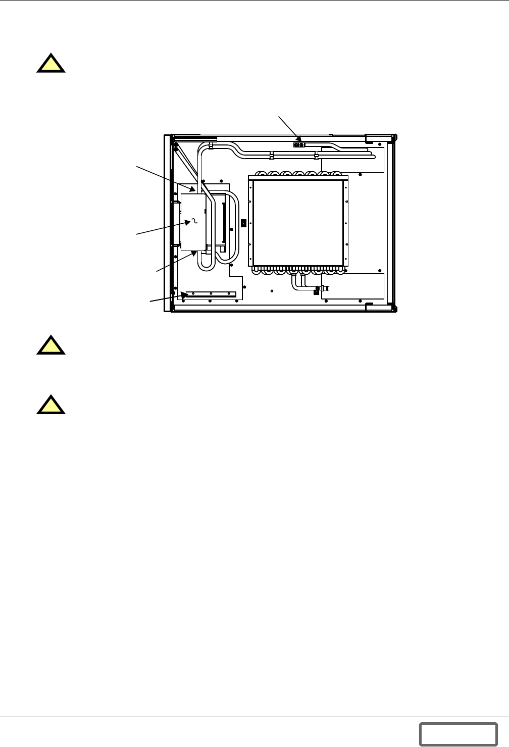
UPS Interconnection Kits
85
Power and status/control wiring must be run in separate conduits or cable trays. Refer to Appendix
D.0 - Installation Drawings for locations of the various electrical connections between Liebert FS
system(s) and UPS system.
Figure 95 Top view of Liebert FS Cabinet with UPS interconnection kit
!CAUTION
Power and status/control wiring must be separated
!CAUTION
Do not cut entry holes for conduit while the access plates are still set on the top of the
Liebert FS cabinet. Remove the access plates from the cable-access areas in the top of the
Liebert FS cabinet prior to cutting entry holes.
!CAUTION
After reinstalling access plates, be certain that no foreign matter (metal shavings, insulation
or wire fragments, etc.) remains inside the Liebert FS. Likewise, be certain to block any
“extra holes” in the plates through which foreign matter (or rodents) could later enter the
Liebert FS.
DC Power
Terminals
Front Rear
Circuit
Breaker
Status/Control
Terminal Block
(upgraded)
Manufacturer’s
Connection
Fan Coil Module
Ground Terminal
DISCONTINUED
PROD UC T
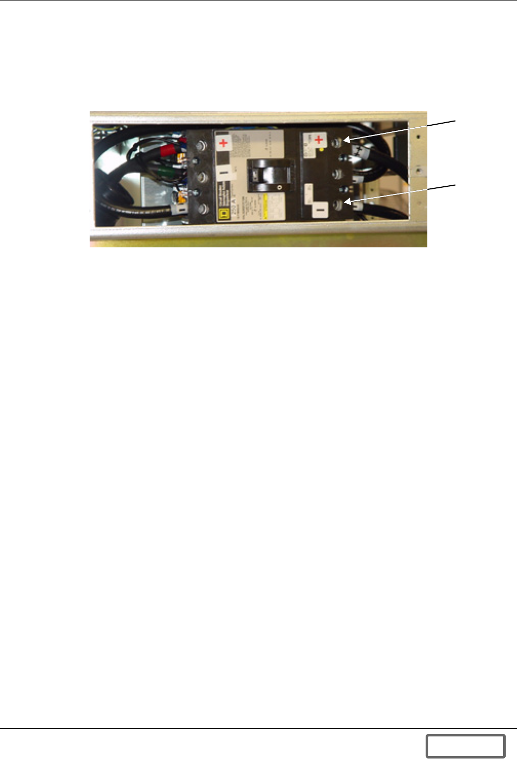
UPS Interconnection Kits
86
Appendix A.1.2 DC Power Connections
The DC power connections to the Liebert FS are made through the circuit breaker (see Figure 96) in
the UPS interconnection kit installed in your Liebert FS. The maximum wire size for the circuit
breaker terminals is 350MCM - 600VDC (approximate metric equivalent: 150mm2 wire section). Wire
size and installation must comply with all applicable local, regional and national regulations (e.g.,
National Electric Code for USA).
Figure 96 Circuit breaker
The Liebert FS cabinet is configured for top entry cables in standard configuration. The cables can
also be run through the side panels. The Liebert FS cabinet does not accommodate bottom entry
cables.
The connection of the circuit breaker is described in Figure 135 - Elevation drawing—Liebert FS
cabinet with integrated circuit breaker. Refer to this drawing to ensure that the adequate con-
nections are performed.
Circuit Breaker Torque
Tighten the positive and negative terminals of the DC power connections on the circuit breaker to
250 in-lb. (29 N-m) unless the equipment is labeled with a different torque value.
Liebert FS
Negative
Terminal
Liebert FS
Positive
Terminal
DISCONTINUED
PROD UC T
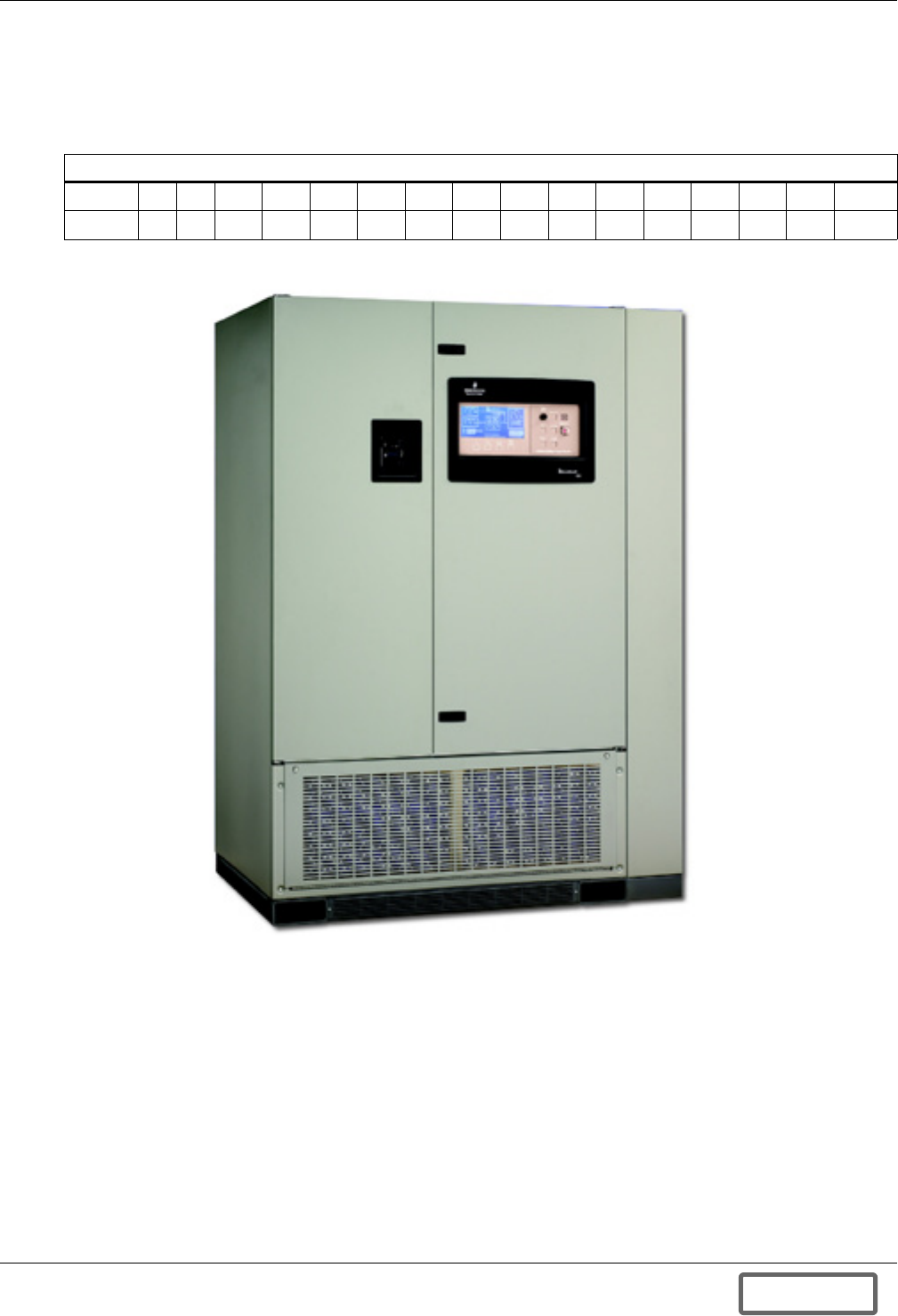
UPS Interconnection Kits
87
Appendix A.2 Installing the Liebert FS With a Liebert Series 610, Liebert Series 600T or
Liebert Series 600
The Liebert Series 610/600T/600 UPS interconnection kit for the Liebert FS is compatible with the
Liebert Series 610, Liebert Series 600T and Liebert Series 600 models in Table 19.
Figure 97 Liebert Series 610 225kVA UPS
Appendix A.2.1 Description - Liebert Series 610/600T/600 UPS Interconnection Kit
The Liebert Series 610/600T/600 UPS interconnection kit for the Liebert FS is composed of:
DC Power Interface
One Thermal-Magnetic Molded Case circuit breaker rated for 250 ADC - 600VDC equipped with:
• An undervoltage relay (UVR) rated for 48VDC, 50 mA
• Auxiliary contacts: Normally Open (NO) and Normally Closed (NC).
Status/Control Interface
One Status/Control Terminal Block used to ensure the status/control connections between the
Liebert FS and the Liebert Series 610/600T/600.
Table 19 Liebert Series 610/600T/600 model ratings
UPS Output Rating
kVA 65 80 100 125 150 225 300 400 400 450 500 500 625 750 750 1,000
kW 52 64 80 100 120 180 240 320 360 360 400 450 500 600 675 900
DISCONTINUED
PROD UC T
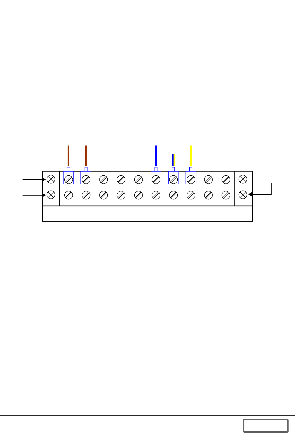
UPS Interconnection Kits
88
Appendix A.2.2 Status/Control Connections - Liebert Series 610/600T/600 UPS Interconnection Kit
The status/control interface is the Status/Control Terminal Block. The connection of the Status/Con-
trol Terminal Block is described in Figure 137 - Control wiring diagram—Liebert FS cabinet -
manually operated circuit breaker. Refer to this drawing to ensure that proper connections are
performed. In case multiple Liebert FS units are connected to the same UPS DC bus, refer to Figure
129 - Control wiring—external interconnect diagram, Liebert FS cabinet to Liebert Series
610 UPS module to perform the Status/Control connections between each Liebert FS.
This interconnection kit includes Status/Control Connections that enable transfer of signals between
the Liebert FS system(s) and the UPS system such as:
• Circuit breaker status (closed/open); and
• Undervoltage relay coil excitation voltage.
Figure 98 Liebert Series 610/600T/600 status/control terminal block wiring
The recommended gauge for Status/Control connection wires is 16 AWG - 600VDC (1.3mm2 wire sec-
tion). Wire size and installation must comply with all applicable local, regional and national regula-
tions (e.g., National Electric Code for USA).
Appendix A.2.3 UPS Configuration - Liebert FS and Liebert Series 610, 600T or 600
To optimize the integration between the Liebert Series 610/600T/600 UPS system and the Liebert FS,
some parameters must be checked on the UPS system:
• The UPS rectifier walk-in time must be set as short as possible. Contact your Liebert representa-
tive if your unit has received the upgraded board that enables the setting of “rectifier walk-in
time” lower than standard.
• Ensure that the “auto battery self test” has either been disabled or upgraded to accommodate
Liebert FS integration.
42 3 5 7 8 961 10
B
l
u
eYellow/
Blue
Y
e
l
l
o
w
Two rows
Row for
installation of
contractor wire
connections
B
r
o
w
n
B
r
o
w
n
DISCONTINUED
PROD UC T
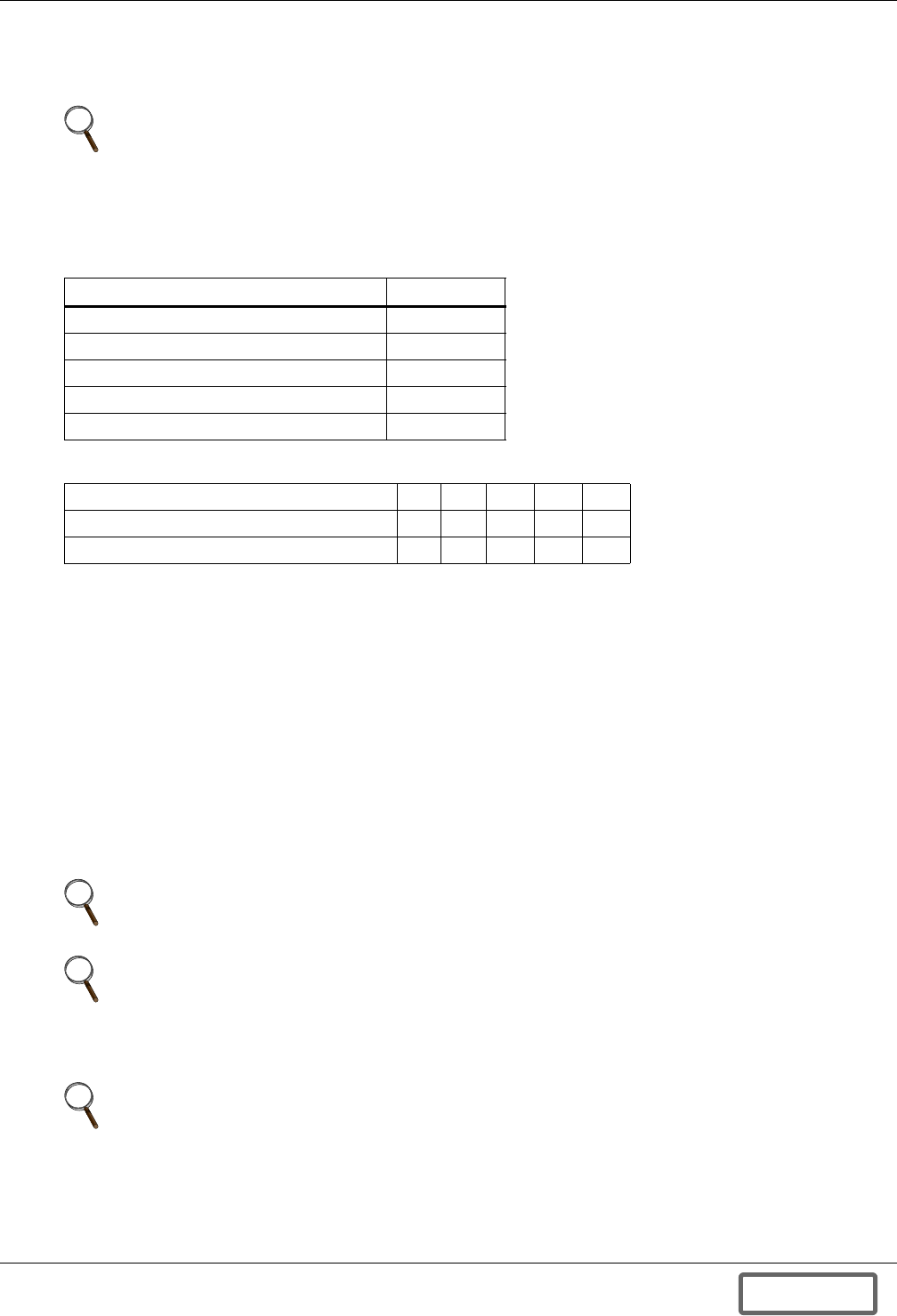
UPS Interconnection Kits
89
Appendix A.2.4 Liebert FS Configuration - Single Liebert FS on Liebert Series 610/600T/600 DC Bus
The following Software Control Parameters must be set when the Liebert FS is connected to the DC
bus of the Liebert Series 610/600T/600 UPS system.
Instructions to set these parameters on the Liebert FS are in 6.5.3 - Control Parameters Setup at
Initial System Startup.
Appendix A.2.5 Liebert FS Configuration - Multiple Liebert FS Units on Liebert Series 610/600T/600
DC Bus
The Liebert FS Software Control Parameters must be reset when multiple Liebert FS units are con-
nected in parallel on the DC bus of a Liebert Series 610/600T/600 UPS system.
Instructions to set these parameters on the Liebert FS are in 6.5.3 - Control Parameters Setup at
Initial System Startup.
Multiple Liebert FS Parallel Operation - Regular Configuration with Liebert Series 610/
600T/600
The Liebert FS Software Control Parameters must be reset when multiple Liebert FS units are con-
nected in parallel on the DC bus of a Liebert Series 610/600T/600 UPS system for proper operation
with longer run times or higher backup power requirements. The Liebert FS units will contribute all
together at the same time to the task of supporting the UPS DC bus.
NOTE
The Software Control Parameter values specified below are recommended. These values may
require adjustments due to the battery type. These must be used unless otherwise specified by
the Liebert-certified service technician at initial system startup.
Table 20 Liebert FS Software Control Parameter settings
Liebert FS Software Control Parameter Setting
Charge Voltage 530VDC
Regulation Voltage 520VDC
Vreg Delta 0VDC
Maximum Charge Current See Table 21
Charge Amps/Volts See Table 21
Table 21 Liebert FS Software Control Parameters varying with UPS size
UPS Output Rating (kVA) 65 80 100 125 150
Liebert FS Maximum Charge Current (A) 25 31 39 49 50
Liebert FS Charge Amps/Volts (A/V) 1.7 2.1 2.6 3.3 3.4
NOTE
This configuration is recommended for UPS models with output power levels greater than
150 kVA (i.e., 225, 300, 400, 450, 500, 625, 750 and 1,000 kVA).
NOTE
In this configuration, the UPS DC bus usually does NOT have batteries in parallel with the
Liebert FS units, however, parallel operation with batteries is acceptable. If batteries to be used
are in parallel with the Liebert FS units on the UPS DC bus, contact your local Liebert sales
representative to arrange a review of the application.
NOTE
Your Liebert-certified service technician will configure the Software Control Parameter values
at initial system startup depending on the number of paralleled units.
DISCONTINUED
PROD UC T
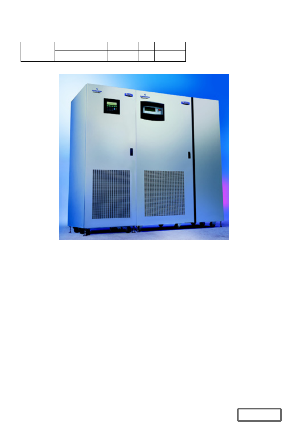
UPS Interconnection Kits
90
Appendix A.3 Installing the Liebert FS With a Liebert Npower UPS
The Liebert Npower UPS interconnection kit for the Liebert FS is compatible with the Liebert
Npower models in Table 22.
Figure 99 Liebert FS integrated into a Liebert Npower UPS system
Appendix A.3.1 Description - Liebert Npower UPS Interconnection Kit
The Liebert Npower UPS interconnection kit for the Liebert FS is composed of:
DC Power Interface
One Thermal-Magnetic Molded Case circuit breaker rated for 250 ADC - 600VDC equipped with:
• An undervoltage relay (UVR) rated for 24VDC, 50 mA
• Auxiliary contacts: Normally Open (NO) and Normally Closed (NC).
Status/Control Interface
One Liebert Npower Battery Information Board (BIB). This board is used to ensure the status/
control connections between the Liebert FS and the Liebert Npower.
Table 22 Liebert Npower model ratings
UPS
Output
Rating
kVA 30 40 50 65 80 100 130
kW 24 32 40 52 64 80 104
Liebert
Npower UPS
Liebert FS
DISCONTINUED
PROD UC T
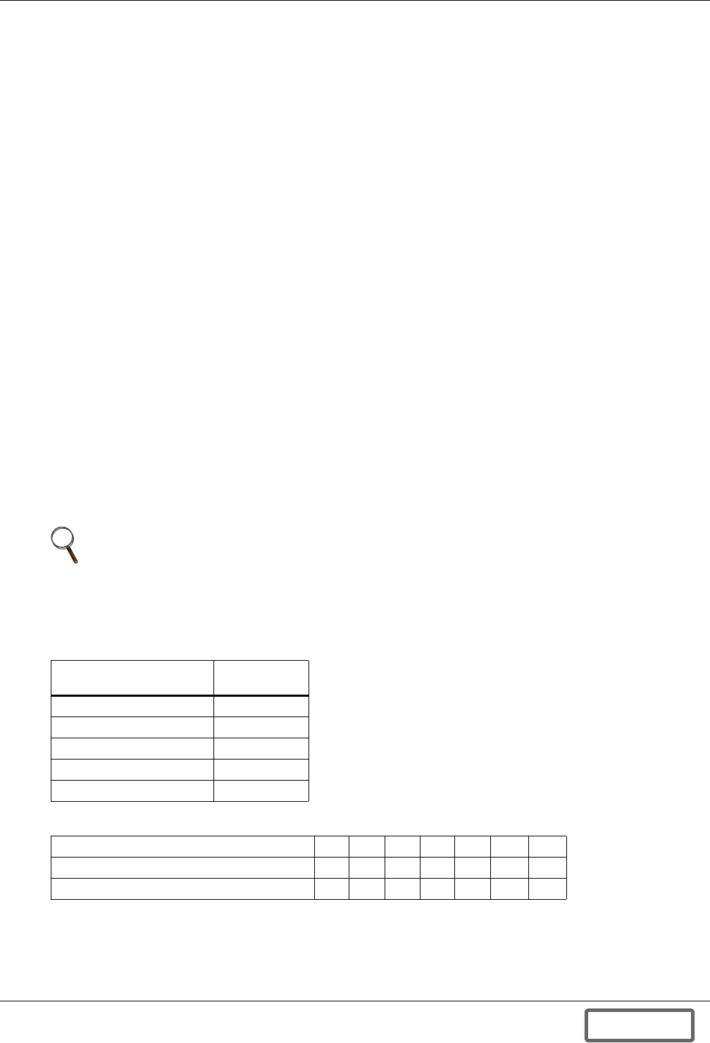
UPS Interconnection Kits
91
Appendix A.3.2 Status/Control Connections - Liebert Npower UPS Interconnection Kit
The status/control interface is the Liebert Npower Battery Information Board (BIB). The connection
of the BIB is described in Figure 140 - Control wiring diagram—Liebert FS - optional electri-
cally operated circuit breaker Liebert Npower units. Refer to this drawing to ensure that the
proper connections are performed. In case multiple Liebert FS units are connected to the same UPS
DC bus, refer to Figure 132 - Control wiring diagram, Liebert FS power rack system in paral-
lel for capacity to perform the Status/Control connections between each Liebert FS.
This interconnection kit includes Status/Control Connections that enable transfer of signals between
the Liebert FS system(s) and the UPS system such as:
• Circuit breaker status (closed/open); and
• Undervoltage relay coil excitation voltage.
The recommended gauge for status/control connection wires is 16 AWG - 600VDC (1.3mm2 wire sec-
tion). Wire size and installation must comply with all applicable local, regional and national regula-
tions (e.g., National Electric Code for USA).
Appendix A.3.3 UPS Configuration - Liebert FS and Liebert Npower
To optimize the integration between the Liebert Npower UPS system and the Liebert FS, some
parameters must be checked on the UPS system:
• The UPS rectifier walk-in time must be set at a value as low as possible. Contact your Liebert rep-
resentative if your unit has received the upgraded board that permits the setting of “rectifier
walk-in time” lower than standard.
• Ensure that the “auto battery self test” has either been disabled or upgraded to accommodate
Liebert FS integration.
Appendix A.3.4 Liebert FS Configuration - Single Liebert FS Unit
The following Software Control Parameters must be set when the Liebert FS is connected to the
DC bus of the Liebert Npower UPS system.
NOTE
The Software Control Parameter values specified below are recommended. These values may
require adjustments due to the battery type. These must be used unless otherwise specified by
the Liebert-certified service technician at initial system startup. Instructions to set these
parameters on the Liebert FS are in 6.5.3 - Control Parameters Setup at Initial System
Startup.
Table 23 Liebert FS Software Control Parameters
Liebert FS Software
Control Parameter Setting
Charge Voltage 530VDC
Regulation Voltage 520VDC
Vreg Delta 0VDC
Maximum Charge Current See Table 24
Charge Amps/Volts See Table 24
Table 24 Liebert FS Software Control Parameters varying with UPS size
UPS Output Rating (kVA) 30 40 50 65 80 100 130
Liebert FS Maximum Charge Current (A) 11 15 19 25 31 38 50
Liebert FS Charge Amps/Volts (A/V) 0.8 1.0 1.3 1.7 2.1 2.6 3.4
DISCONTINUED
PROD UC T

UPS Interconnection Kits
92
Appendix A.3.5 Liebert FS Configuration - Multiple Liebert FS Units on Liebert Npower DC Bus
Liebert FS Software Control Parameters must be reset when multiple Liebert FS units are connected
in parallel on the DC bus of a Liebert Npower UPS system for proper operation with longer run times
or higher backup power requirements.
Instructions to set these parameters on the Liebert FS are in 6.5.3 - Control Parameters Setup at
Initial System Startup.
NOTE
In this configuration, the UPS DC bus usually does NOT have batteries in parallel with the
Liebert FS units, however, parallel operation with batteries is acceptable. If batteries to be used
are in parallel with the Liebert FS units on the UPS DC bus, contact your local Liebert sales
representative to arrange a review of the application.
NOTE
Your Liebert-certified service technician will configure the Software Control Parameter values
at initial system startup depending on the number of paralleled units.
DISCONTINUED
PROD UC T
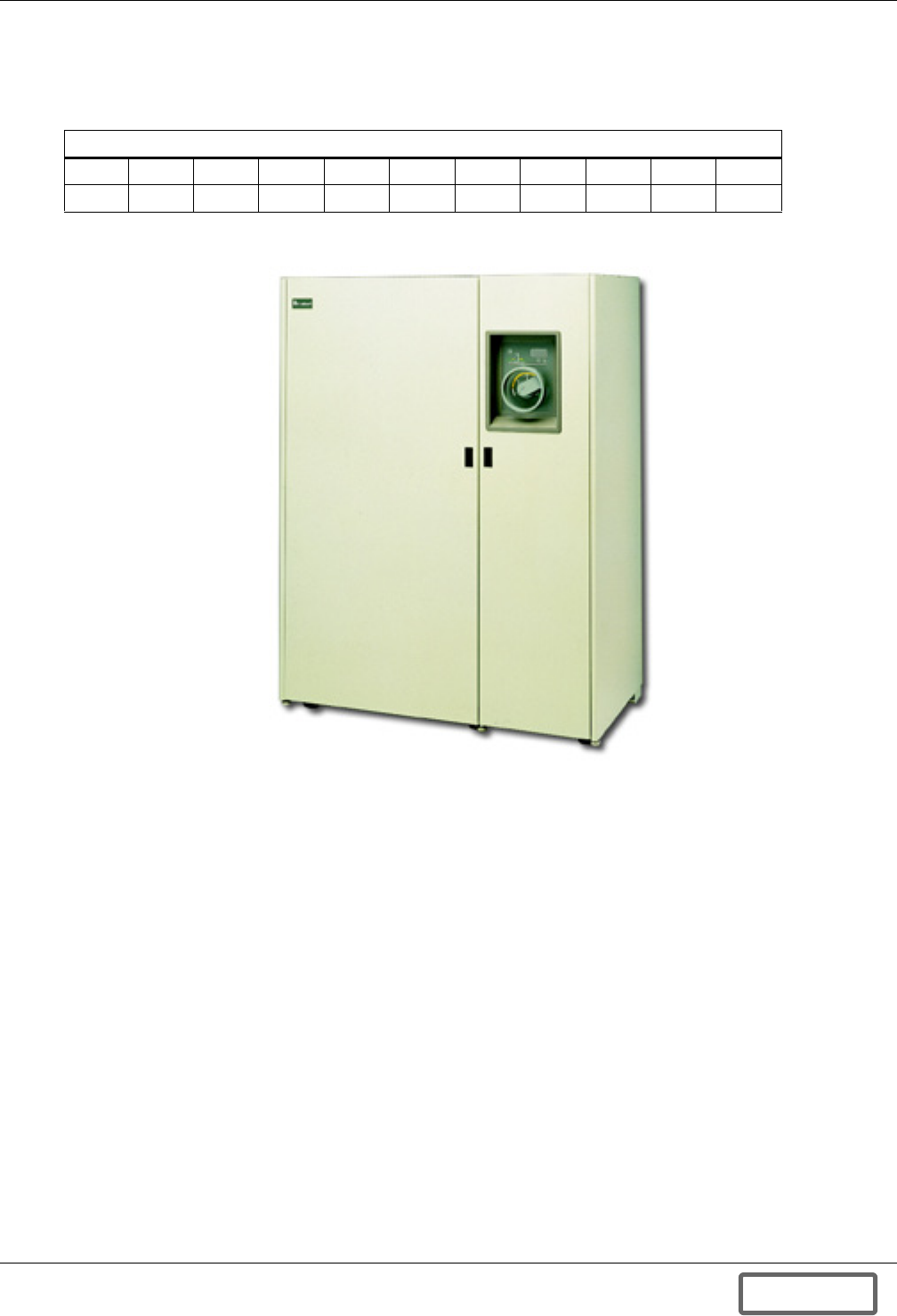
UPS Interconnection Kits
93
Appendix A.4 Installing the Liebert FS With a Liebert Series 300 UPS
The Liebert Series 300 UPS interconnection kit for the Liebert FS is compatible with the Liebert
Series 300 models in Table 25.
Figure 100 Liebert Series 300 UPS
Appendix A.4.1 Description - Liebert Series 300 UPS Interconnection Kit
The Liebert Series 300 UPS interconnection kit for the Liebert FS is composed of:
DC Power Interface
One Thermal-Magnetic Molded Case circuit breaker rated for 250 ADC - 600VDC equipped with:
• An undervoltage relay (UVR) rated for 24VDC, 50 mA
• Auxiliary contacts: Normally Open (NO) and Normally Closed (NC).
Status/Control Interface
One status/control terminal Block used to ensure the status/control connections between the
Liebert FS and the Liebert Series 300.
Table 25 List of Liebert Series 300 models ratings
UPS Output Rating
kVA 10 15 20 30 40 50 65 75 100 125
kW 8 12 16 24 32 40 52 60 80 100
DISCONTINUED
PROD UC T
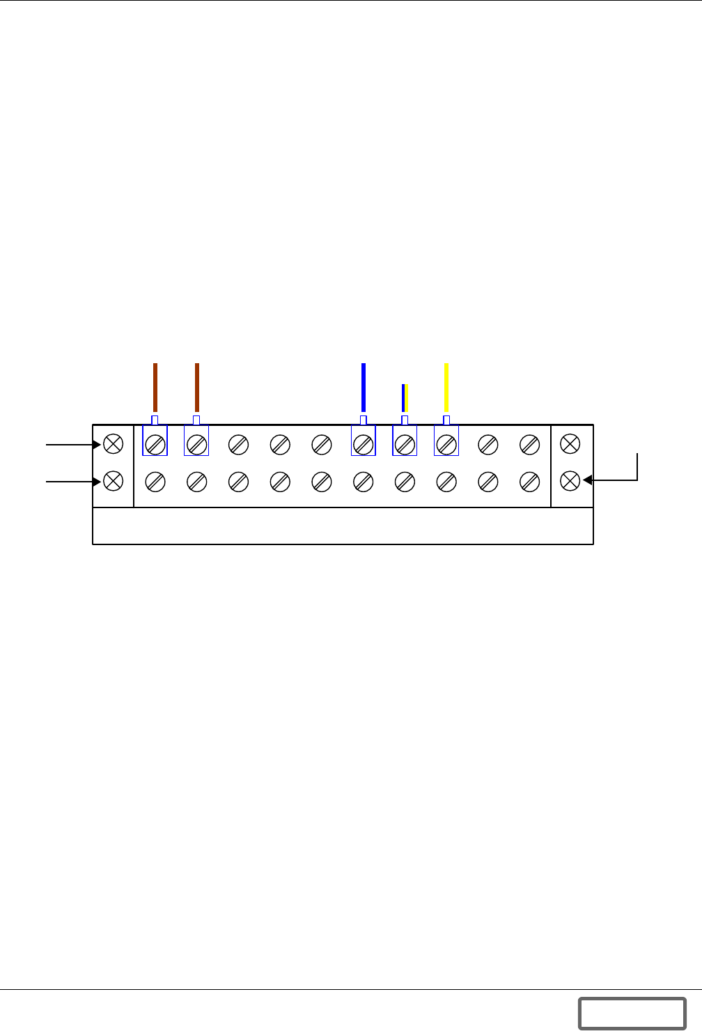
UPS Interconnection Kits
94
Appendix A.4.2 Status/Control Connections - Liebert Series 300 UPS Interconnection Kit
The status/control interface is the Status/Control Terminal Block. The connection of the Status/Con-
trol Terminal Block is described in the Figure 137 - Control wiring diagram—Liebert FS cabi-
net - manually operated circuit breaker. Refer to this drawing to ensure that the adequate
connections will be performed. If multiple Liebert FS units are connected to the same UPS DC bus,
refer to Figure 129 - Control wiring—external interconnect diagram, Liebert FS cabinet to
Liebert Series 610 UPS module to perform the Status/Control connections between each
Liebert FS.
This interconnection kit includes status/control connections that enable transfer of signals between
the Liebert FS system(s) and the UPS system such as:
• Circuit breaker status (closed/open); and
• Undervoltage relay coil excitation voltage
Figure 101 Liebert Series 300 status/control terminal block wiring
The recommended gauge for status/control connection wires is 16 AWG - 600VDC (1.3mm2 wire sec-
tion). Status/Control wires must be sized and installed in compliance with all applicable local,
regional and national regulations (e.g., National Electric Code for USA).
Appendix A.4.3 UPS Configuration - Liebert FS and Liebert Series 300
To optimize the integration between the Liebert Series 300 UPS system and the Liebert FS, some
parameters must be checked on the UPS system:
• The UPS rectifier walk-in time must be set at a value as low as possible. Contact your Liebert rep-
resentative if your unit has received the upgraded board that enables the setting of “rectifier
walk-in time” lower than standard.
• Ensure that the “auto battery self test” has been either disabled or upgraded to accommodate
Liebert FS integration.
42 3 5 7 8 961 10
B
l
u
eYellow/
Blue
Y
e
l
l
o
w
Two rows
Row for
installation of
contractor wire
connections
B
r
o
w
n
B
r
o
w
n
DISCONTINUED
PROD UC T
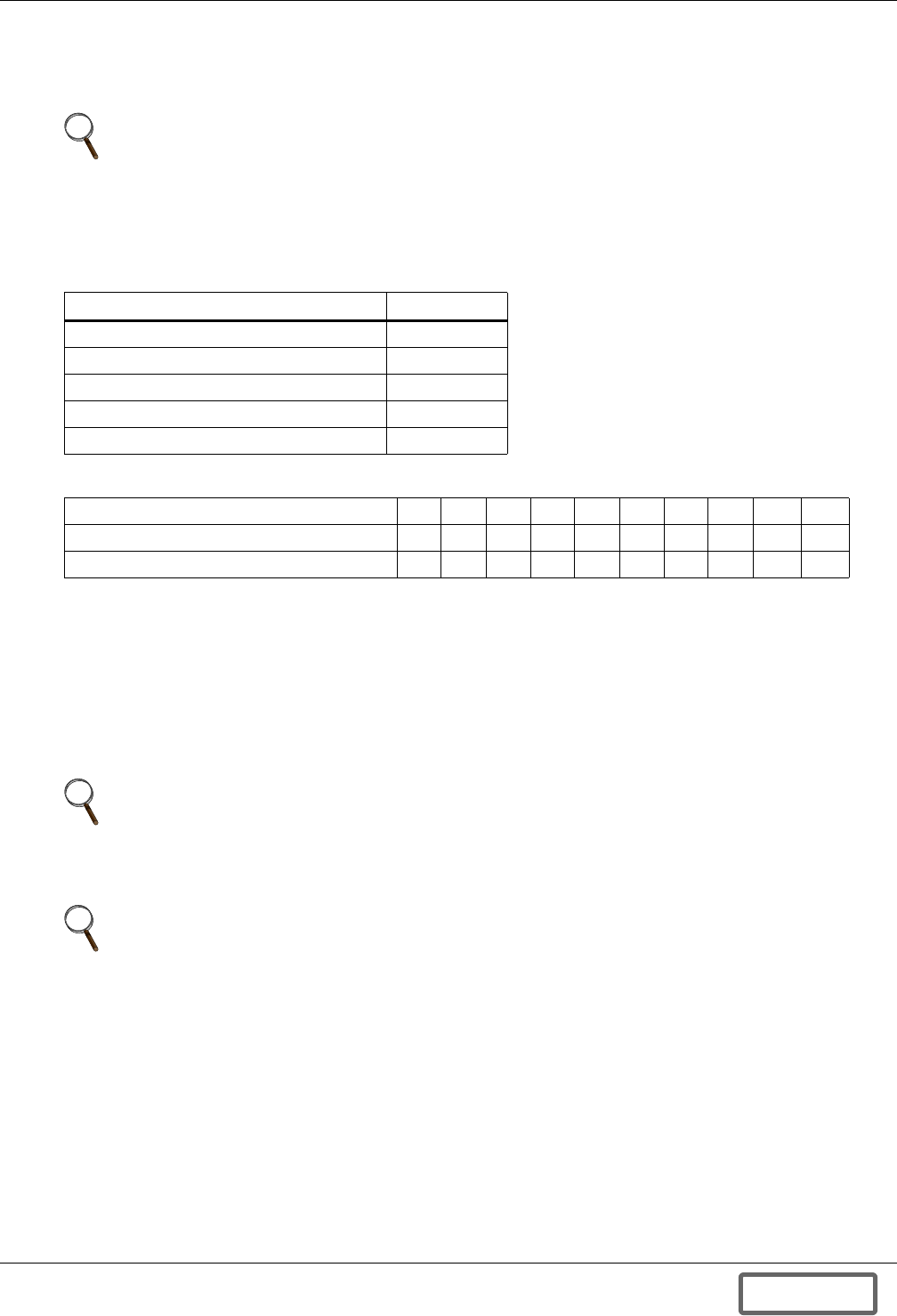
UPS Interconnection Kits
95
Appendix A.4.4 Liebert FS Configuration - Single Liebert FS on Series 300 DC Bus
The following Software Control Parameters must be reset when the Liebert FS is connected to the DC
Bus of the Liebert Series 300 UPS system.
Instructions to set these parameters on the Liebert FS are in 6.5.3 - Control Parameters Setup at
Initial System Startup.
Appendix A.4.5 Liebert FS Configuration - Multiple Liebert FS Units on Liebert Series 300 DC
Bus
Liebert FS Software Control Parameters must be reset when multiple Liebert FS units are connected
in parallel on the DC bus of a Liebert Series 300 UPS system for proper operation with longer run
times or higher backup power requirements.
Instructions to set these parameters on the Liebert FS are in 6.5.3 - Control Parameters Setup at
Initial System Startup.
NOTE
The Software Control Parameter values specified below are recommended. These values may
require adjustments due to the battery type. These must be used unless otherwise specified by
the Liebert-certified service technician at initial system startup.
Table 26 Liebert FS Software Control Parameter settings
Liebert FS Software Control Parameter Setting
Charge Voltage 395VDC
Regulation Voltage 385VDC
Vreg Delta 0VDC
Maximum Charge Current See Table 27
Charge Amps/Volts See Table 27
Table 27 Liebert FS Software Control Parameters varying with UPS size
UPS Output Rating (kVA) 10 15 20 30 40 50 65 75 100 125
Liebert FS Maximum Charge Current (A) 5 8 10 16 21 26 34 39 50 50
Liebert FS Charge Amps/Volts (A/V) 0.7 1.1 1.4 2.1 2.8 3.5 4.5 5.2 6.7 6.7
NOTE
In this configuration, the UPS DC bus usually does NOT have batteries in parallel with the
Liebert FS units, however, parallel operation with batteries is acceptable. If batteries to be used
are in parallel with the Liebert FS units on the UPS DC bus, contact your local Liebert sales
representative to arrange a review of the application.
NOTE
Your Liebert-certified service technician will configure the Software Control Parameter values
at initial system startup depending on the number of paralleled units.
DISCONTINUED
PROD UC T
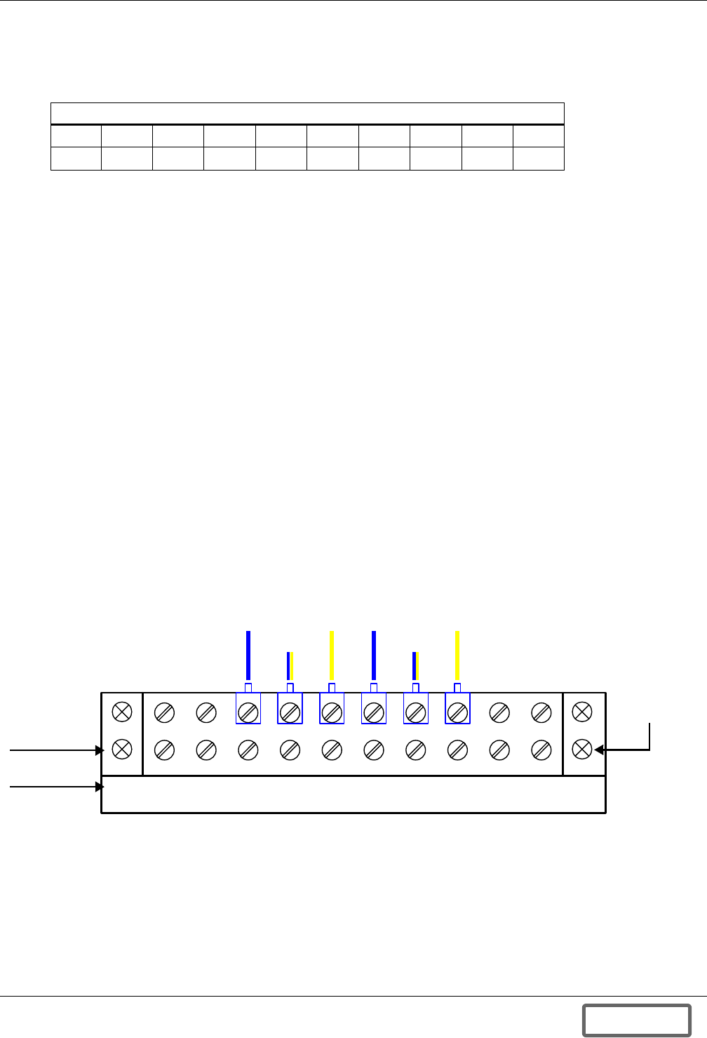
UPS Interconnection Kits
96
Appendix A.5 Installing the Liebert FS With a Liebert HiPulse UPS
The Liebert HiPulse UPS interconnection kit for the Liebert FS is compatible with the Liebert
HiPulse™ models in Table 28.
Appendix A.5.1 Description—HiPulse UPS Interconnection Kit
HiPulse UPS interconnection kit is composed of:
DC Power Interface
One Thermal-Magnetic Molded Case circuit-breaker rated for 250 ADC, 600VDC equipped with
auxiliary contacts: two (2) sets of Normally Open (NO) and Normally Closed (NC).
Status/Control Interface
One Status/Control Terminal Block used to ensure the status/control connections between the
Liebert FS and the Liebert HiPulse.
Appendix A.5.2 Status/Control Connections—Liebert HiPulse UPS Interconnection Kit
The status/control interface of the IKIT-A05 is the Status/Control Terminal Block. The connection of
the Status/Control Terminal Block is illustrated in Figure 102. Please refer to this drawing to ensure
that the proper connections are made. In case multiple Liebert FS units are connected to the same
UPS DC bus, please refer to Figure 144 to perform the Status/Control connections between each
Liebert FS.
This IKIT includes Status/Control Connections that enable transfer of “IKIT circuit-breaker status
(closed/open)” signals between the Liebert FS system(s) and the UPS system.
Figure 102 Liebert HiPulse status/control terminal block wiring
The recommended gauge for Status/Control Connection wires is 16 AWG – 600 VDC (approximate
metric equivalent: 1.3 mm² wire section). All wiring must comply with all applicable local, regional,
national regulations.
Table 28 Liebert HiPulse model ratings
UPS Output Rating
kVA 80 120 160 200 300 400 500 600 800
kW 64 96 128 160 240 320 400 480 640
42 3 5 7 8 961 10
Two rows
B
l
u
e
B
l
u
e
Y
e
l
l
o
w
Y
e
l
l
o
w
Yellow/
Blue
Yellow/
Blue
Row for
installation of
contractor wire
connections
DISCONTINUED
PROD UC T
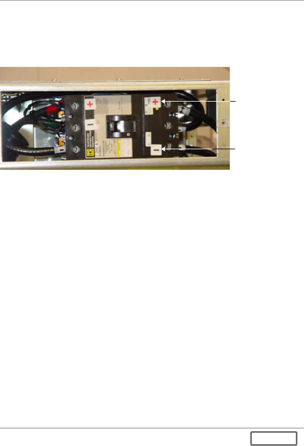
UPS Interconnection Kits
97
Appendix A.5.3 IKIT-A05 DC Power Connections
The DC power connections to the Liebert FS are made through the circuit-breaker (see Figure 103)
in the IKIT-A05. The minimum wire size to be used is 1/0 AWG - 600VDC wire (54 mm2 wire section).
The maximum wire size for the circuit-breaker terminals is 350MCM – 600VDC (150 mm2 wire sec-
tion). All wiring must comply with all applicable local, regional, national regulations. Use copper con-
ductors only, rated minimum 140°F (60°C).
Figure 103 Circuit-breaker (open door and cabinet faceplate removed)
The Liebert FS cabinet is configured for top entry cables in standard configuration. The cables can
also be run through the side panels. The Liebert FS cabinet does not accommodate bottom entry
cables.
The connection of the circuit-breaker is described in Figure 135 - Elevation drawing—Liebert FS
cabinet with integrated circuit breaker. Refer to this drawing to ensure that the proper connec-
tions are made.
Circuit Breaker Torque
Tighten the positive and negative terminals of the DC power connections on the circuit breaker to
250 in-lb. (29 N-m) unless the equipment is labeled with a different torque value.
Appendix A.5.4 UPS Configuration—Liebert FS and Liebert HiPulse
To optimize the integration between the interconnected UPS system and the Liebert FS, some param-
eters must be checked on the UPS system:
• The UPS rectifier walk-in time must be set at a value as low as possible. Please check with your
UPS Manufacturer representative if your unit has received the upgraded board that enables the
setting of “rectifier walk-in time” lower than standard.
• Check that the “auto battery self test” has either been disabled or upgraded to accommodate
Liebert FS integration.
Liebert FS positive
terminal
Liebert FS negative
terminal
DISCONTINUED
PROD UC T
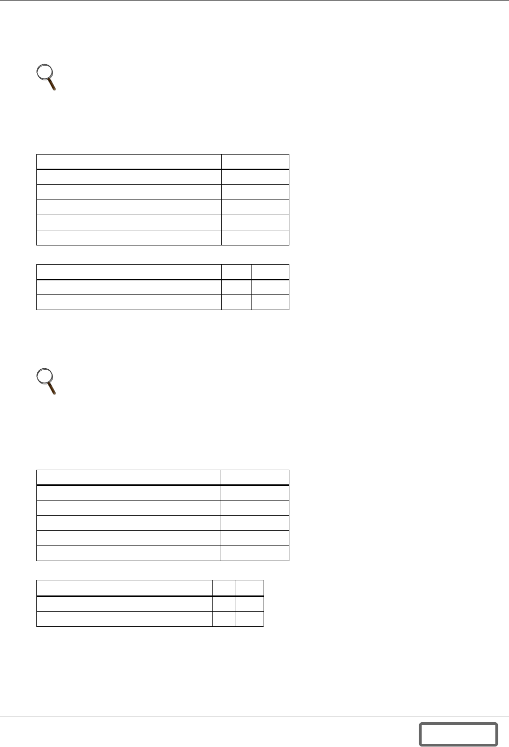
UPS Interconnection Kits
98
Appendix A.5.5 Single Liebert FS on UPS DC Bus
The following Liebert FS Software Control Parameters must be set when a single Liebert FS is con-
nected alone on the DC bus of the Liebert HiPulse UPS system.
Instructions on setting these parameters on the Liebert FS are found in 6.5.3 - Control Parameters
Setup at Initial System Startup.
Appendix A.5.6 Single Liebert FS in Parallel with Battery Pack on UPS DC Bus
The following Software Control Parameters must be reset when the Liebert FS is connected in paral-
lel with a battery pack on the DC bus of the Liebert Hipulse UPS system.
Instructions on setting these parameters on the Liebert FS are found in 6.5.3 - Control Parameters
Setup at Initial System Startup.
NOTE
The Software Control Parameter values specified below must be used unless otherwise
specified by the Liebert-certified service technician at Initial System Startup.
Table 29 Liebert FS Software Control Parameter settings
Liebert FS Software Control Parameter Setting
Charge Voltage 436 VDC
Regulation Voltage 426 VDC
Vreg Delta 0 VDC
Maximum Charge Current See Table 30
Charge Amps/Volts See Table 30
Table 30 Liebert FS Software Control Parameters varying with UPS size
UPS Output Rating (kVA) 80 120
Liebert FS Maximum Charge Current (A) 39 50
Liebert FS Charge Amps/Volts (A/V) 4 5
NOTE
The Software Control Parameter values specified below must be used unless otherwise
specified by the Liebert-certified service technician at Initial System Startup. These values may
require adjustments due to the battery type.
Table 31 Liebert FS Software Control Parameter settings
Liebert FS Software Control Parameter Setting
Charge Voltage 436 VDC
Regulation Voltage 426 VDC
Vreg Delta 0 VDC
Maximum Charge Current See Table 32
Charge Amps/Volts See Table 32
Table 32 Liebert FS Software Control Parameters varying with UPS size
UPS Output Rating (kVA) 80 120
Liebert FS Maximum Charge Current (A) 39 50
Liebert FS Charge Amps/Volts (A/V) 4 5
DISCONTINUED
PROD UC T

UPS Interconnection Kits
99
Appendix A.5.7 Liebert FS Configuration – Multiple Liebert FS Units
Liebert FS Software Control Parameters must be reset when multiple Liebert FS units are connected
in parallel on the DC bus of a Liebert HiPulse™ UPS system.
Instructions to set these parameters on the Liebert FS are found in 6.5.3 - Control Parameters
Setup at Initial System Startup.
Multiple Liebert FS Parallel Operation—Regular Configuration
Liebert FS Software Control Parameters must be reset when multiple Liebert FS units are connected
in parallel on the DC bus of a Liebert HiPulse™ UPS system for proper operation with longer run
times or higher backup power requirements. The Liebert FS units will contribute all together at the
same time to the task of supporting the UPS DC bus.
Instructions on setting these parameters on the Liebert FS are found in 6.5.3 - Control Parameters
Setup at Initial System Startup.
NOTE
In this configuration, the UPS DC bus usually does NOT have batteries in parallel with the
Liebert FS units, however, parallel operation with batteries is acceptable. If batteries to be used
are in parallel with the Liebert FS units on the UPS DC bus, contact your local Liebert sales
representative to arrange a review of the application.
NOTE
Your Liebert-certified service technician will configure the Software Control Parameter values
at Initial System Startup depending on the number of paralleled units.
DISCONTINUED
PROD UC T
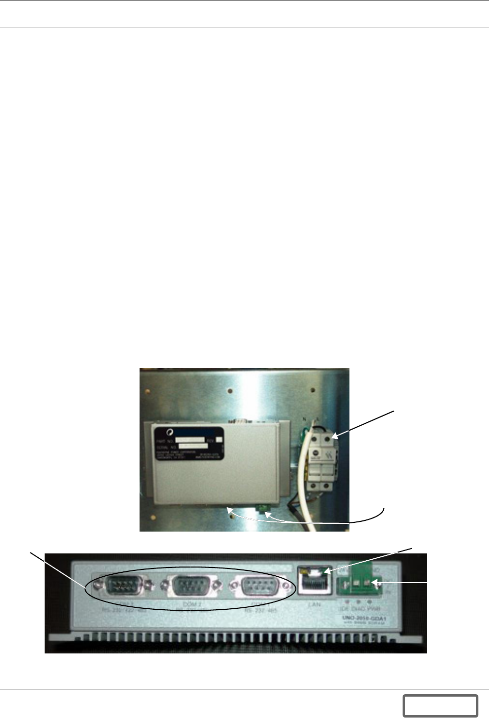
Data Collection Module
100
APPENDIX B.0DATA COLLECTION MODULE
Appendix B.1 General Information
Appendix B.1.1 Overview
The Data Collection Module (DCM) is designed to provide real-time data monitoring and data storage
for the Liebert FS. The DCM collects data on virtually every event that occurs in the Liebert FS. Data
such as speed, temperature and voltage are just a few of the data points that the DCM will be collect-
ing and storing on its internal memory card. The DCM has an HTML interface, which means any
Internet browser, such as Internet Explorer or Netscape, is all that is required to access the
Liebert FS data.
Appendix B.1.2 Features
The DCM comes equipped with four (4) RS-232 communication ports and a 10/100 Base-T RJ-45 port.
The DCM runs on the Linux operating system, which resides on the internal compact flash memory
card. Dynamic Host Configuration Protocol (DHCP) has been enabled on the DCM to allow easy inte-
gration with an existing network.
Appendix B.2 DCM Installation and Configuration
Appendix B.2.1 Installation
The DCM has been installed at the front of the Liebert FS inside the door on the service panel and has
been securely mounted adjacent to the AC auxiliary fused disconnect. The power cable and the serial
communication cable have been connected at the factory as seen in Figure 104.
The DCM has been installed on the inside door of the Liebert FS and has been securely mounted adja-
cent to the Control Panel. The power cable and the serial communication cable have been connected
at the factory as seen in Figure 104.
Figure 104 Data Collection Module location, features
DCM Power and
Serial Connections
Fused
Disconnect
Power
Connection
Serial
Connections Ethernet Port
DISCONTINUED
PROD UC T
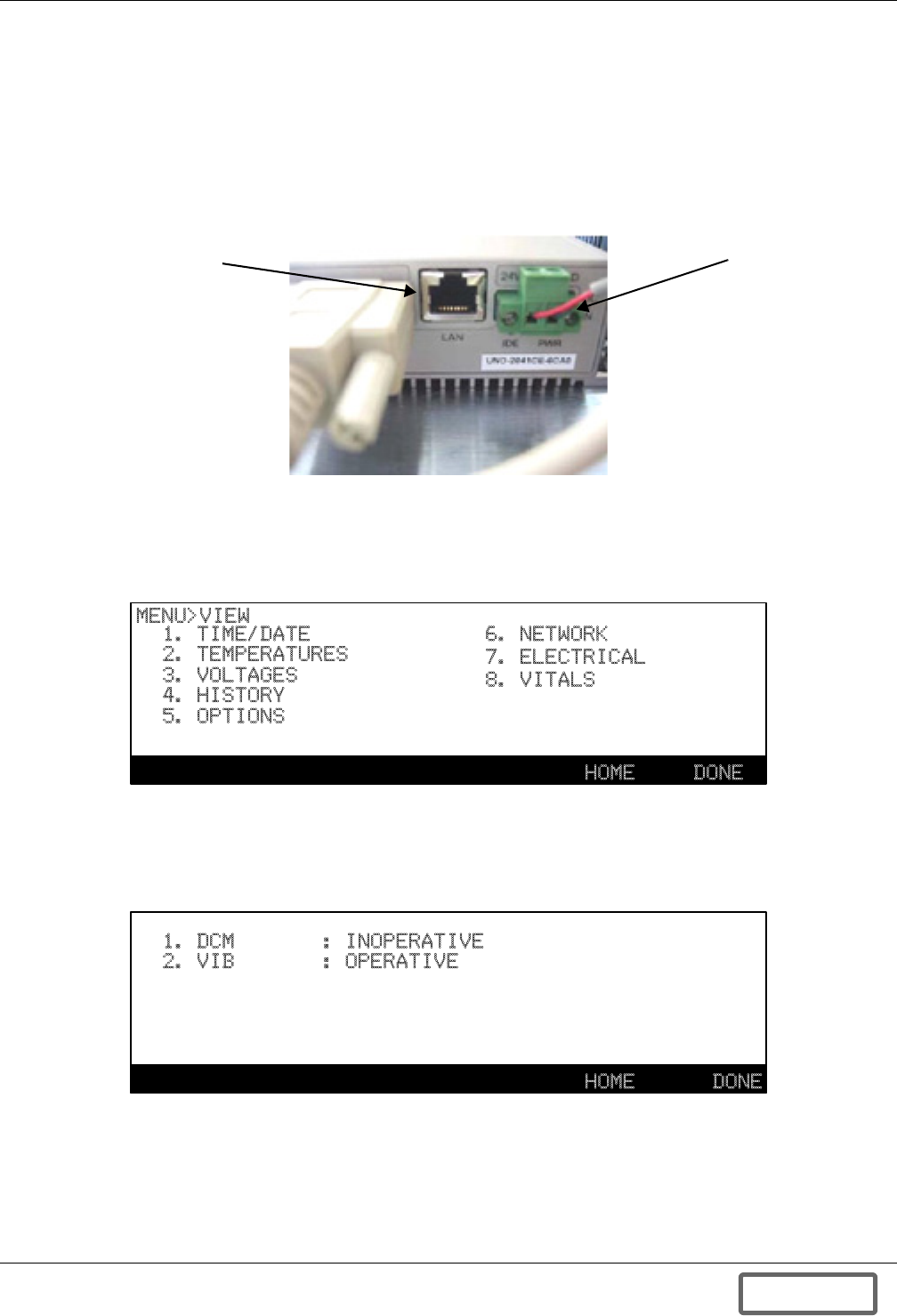
Data Collection Module
101
Appendix B.2.2 DCM Requirements
The Data Collection Module requires a connection to an existing network via an Ethernet cable. An
RJ-45 jack is built directly into the bottom of the faceplate of the DCM and located adjacent to the
power supply connection. The DCM may also be connected via modem through COM2 serial port.
By connecting to your existing network with an Ethernet cable, you will be able to access the DCM via
your Internet browser. Figure 105 displays the LAN connection, which is located on the bottom side
of the DCM.
Figure 105 DCM LAN connection
DHCP is enabled at the factory. A connected DHCP Server automatically assigns an IP Address to
the DCM. To confirm that the DCM is enabled and operative, check the Liebert FS Control Panel.
From the Main Menu Screen, select number 2 “View” screen.
Figure 106 Options view
Select the number 5 “Options” screen to view the current status of the options. To enable or disable
this option, select and press the number 1 for the DCM option. To exit this screen, press the F6 or
“Done” key.
Figure 107 Enable or disable DCM
Power Connection
LAN Connection
1. TIME/DATE
2. TEMPERATURES
3. VOLTAGES
4. HISTORY
5. OPTIONS
6. NETWORK
7. ELECTRICAL
8. VITALS
HOME
MENU>VIEW
DONE
1. DCM
2. VIB
HOME DONE
: INOPERATIVE
: OPERATIVE
DISCONTINUED
PROD UC T
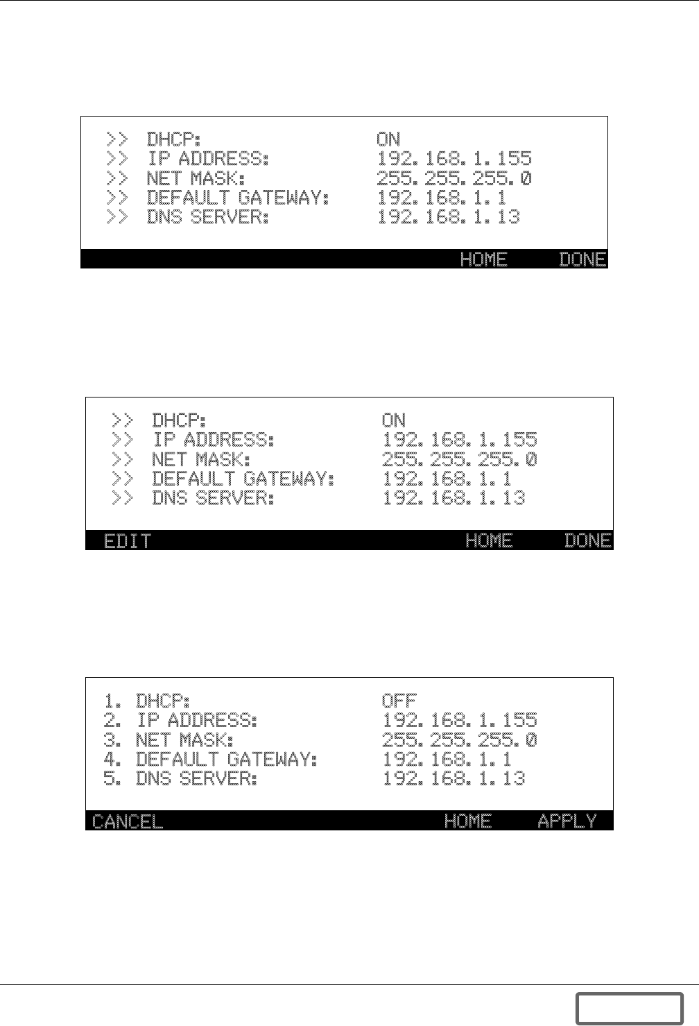
Data Collection Module
102
To view the Network settings return to the View menu and press number 6 “Network”. The Network
view screen displays the network addresses coming from the DCM. Static address settings can be
entered using the keypad into this screen. The Network screen will show the assigned IP Address,
Default Gateway, Subnet Mask and DNS Server.
Figure 108 Networks view
By entering a Password to access the User or Service level mode you can edit this function. Pressing
the EDIT button, F1, will place the system in the edit mode. The DHCP must be disabled or turned
Off to proceed with setting IP addresses and other settings. After pressing EDIT you will see up/down
arrows next to the DHCP On value. Pressing the up or down arrows on the keypad will allow you to
turn this function Off or On.
Figure 109 Networks view, turn off DHCP
Once you have turned DHCP OFF, press EDIT again and now you will see numbers next to each of
the settings. Pressing the corresponding number will allow you to enter or change that value. At any
time you may press CANCEL to cancel the changes, once changes or entries are complete, press
APPLY to complete entry process. Pressing APPLY will reboot system and in a few minutes the sys-
tem will display the new screen.
Figure 110 Networks view, edit settings (service level)
HOME DONE
>>
>>
>>
>>
>>
DHCP:
IP ADDRESS:
NET MASK:
DEFAULT GATEWAY:
DNS SERVER:
ON
192.168.1.155
255.255.255.0
192.168.1.1
192.168.1.13
HOME DONE
>>
>>
>>
>>
>>
DHCP:
IP ADDRESS:
NET MASK:
DEFAULT GATEWAY:
DNS SERVER:
ON
192.168.1.155
255.255.255.0
192.168.1.1
192.168.1.13
EDIT
HOME APPLY
1. DHCP:
2. IP ADDRESS:
3. NET MASK:
4. DEFAULT GATEWAY:
5. DNS SERVER:
OFF
192.168.1.155
255.255.255.0
192.168.1.1
192.168.1.13
CANCEL
DISCONTINUED
PROD UC T
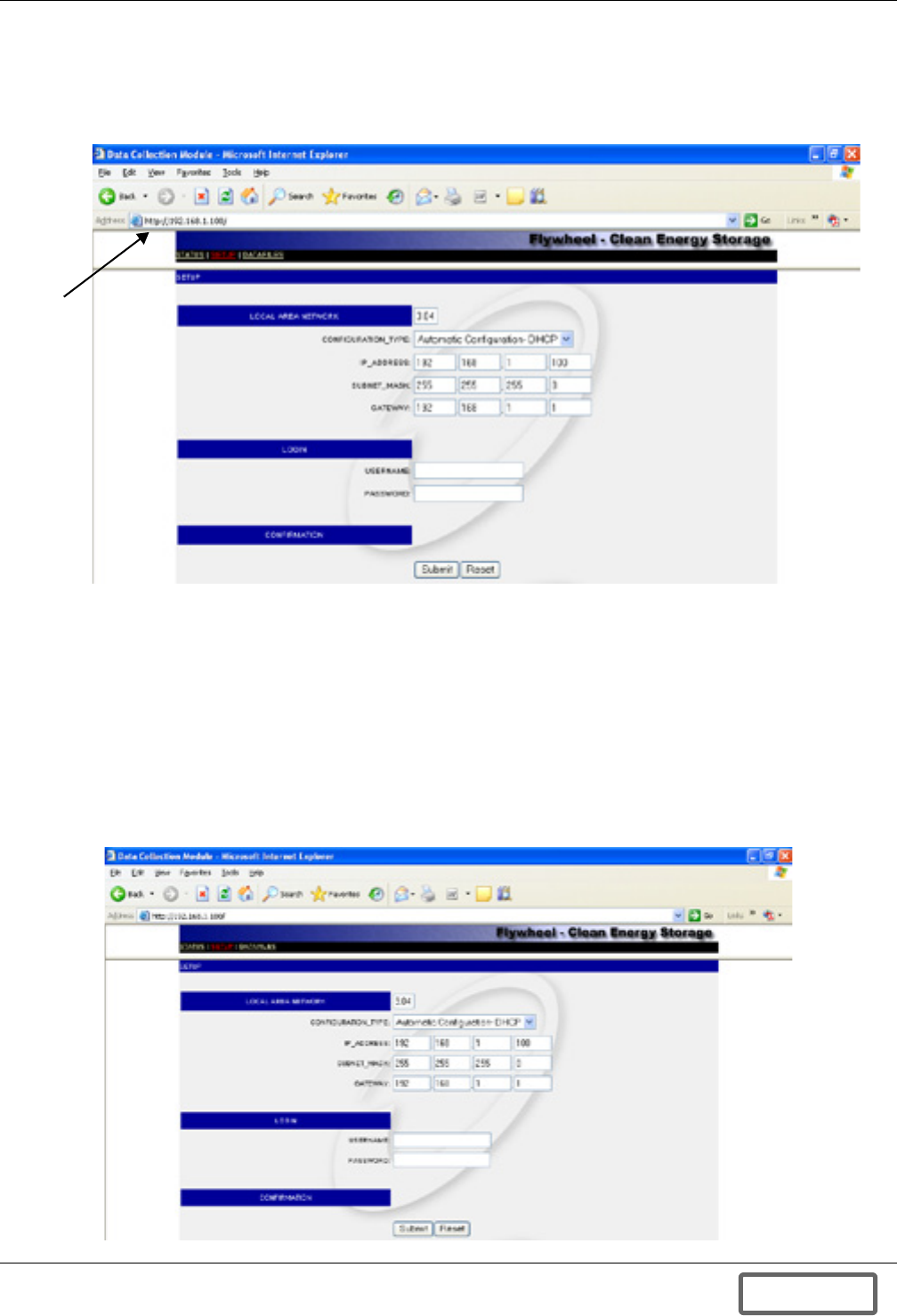
Data Collection Module
103
Appendix B.2.3 Accessing the DCM
From a personal computer connected to the same network as the DCM, enter the IP Address of the
DCM, assigned by the LAN network server or manually configured, into the address line of the Inter-
net browser to gain access to the DCM as seen in Figure 111.
Figure 111 DCM screen
The DCM software has a screen menu bar along the top of the page. Three screens may be accessed:
STATUS, SETUP and DATAFILES. The screens allow for setup of the DCM and different ways to
browse the data recorded by the DCM.
Appendix B.2.4 Configuring DCM System Parameters
One of the tabs in the menu bar is the DCM system “Setup” page. This page will allow you to custom-
ize your DCM settings. For example, you may want to assign a static IP Address to the DCM. There
are seven fields on the Setup page as seen in Figure 112. Enter data in the fields and once you are
done with entries, click the Submit button to enter changes or click Reset to reset the DCM.
The default Username and Password for setup are “hello” and “hello” respectively. Liebert recom-
mends changing both the username and password to prevent unauthorized changes to the system.
Figure 112DCM setup screen
Enter IP
Address
DISCONTINUED
PROD UC T
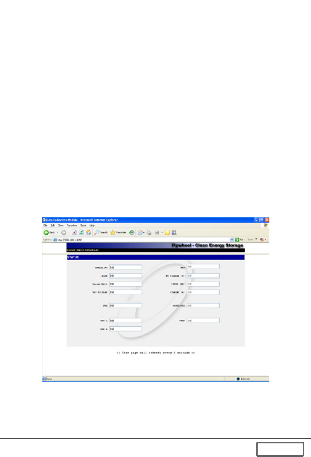
Data Collection Module
104
•Software Version: The current version of the software running on the DCM.
•Configuration Type: Select from the drop-down menu as to whether it is a Static IP Address or
a DHCP server assigned.
•IPAddress: The IP Address of the DCM
•Subnet Mask: The Subnet mask of the DCM
•Gateway: The Gateway of the DCM
•User: The user name to gain access to the DCM.
•Password: The password to gain access to the DCM.
If a parameter setting needs to be changed (i.e., dynamic IP to static IP), please consult your network
administrator for the correct parameters. To save any changes, click the Submit button. The DCM
will automatically reboot itself. You will need to reconnect to the DCM through the browser.
Appendix B.3 DCM Operation
Upon Initial System Startup of the Liebert FS by a Liebert-certified service technician, the DCM will
be operational. There is nothing to turn on or configure.
Appendix B.3.1 Logging into the DCM
Enter the IP Address into the address line of the Internet browser to gain access to the DCM as
shown in Figure 111. The DCM’s IP Address is described in Appendix B.2 - DCM Installation
and Configuration. The first page that appears is the Status Page.
Appendix B.3.2 Status and Detailed Status Screens
The Status page displays various data points from the Liebert FS as shown in Figure 113. Data is
refreshed approximately every five (5) seconds.
Figure 113 DCM status screen
The Status page provides basic system operational data, all data normally found on the Main Screen
of the system Control Panel, such as Mode, RPM and Power.
The Status screen provides more detailed information on system characteristics, such as Serial No.,
and performance. This includes real time information on voltages and temperatures in the system.
DISCONTINUED
PROD UC T
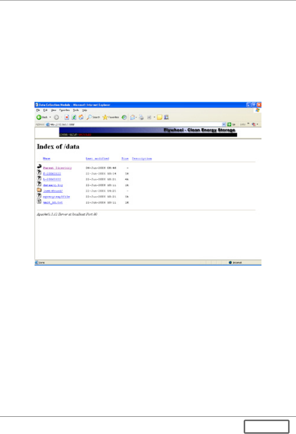
Data Collection Module
105
Appendix B.3.3 Datafiles Screen
This screen lists the different files types for viewing and download. There are five files types: F, S, L,
A and D.
•F indicates a fast data packet, containing electrical information such as voltages, amps and watts.
•S represents a slow packet for measurements collected over a longer period, such as tempera-
tures.
•L stands for Log files and these contain information on system modes, statuses and commands.
•A indicates an alarm file and will contain information on any Faults or Warnings recorded.
•D files indicate a system discharge and allow a user to view the time, duration and amount of Dis-
charge.
Figure 114 Datafiles screen
DISCONTINUED
PROD UC T
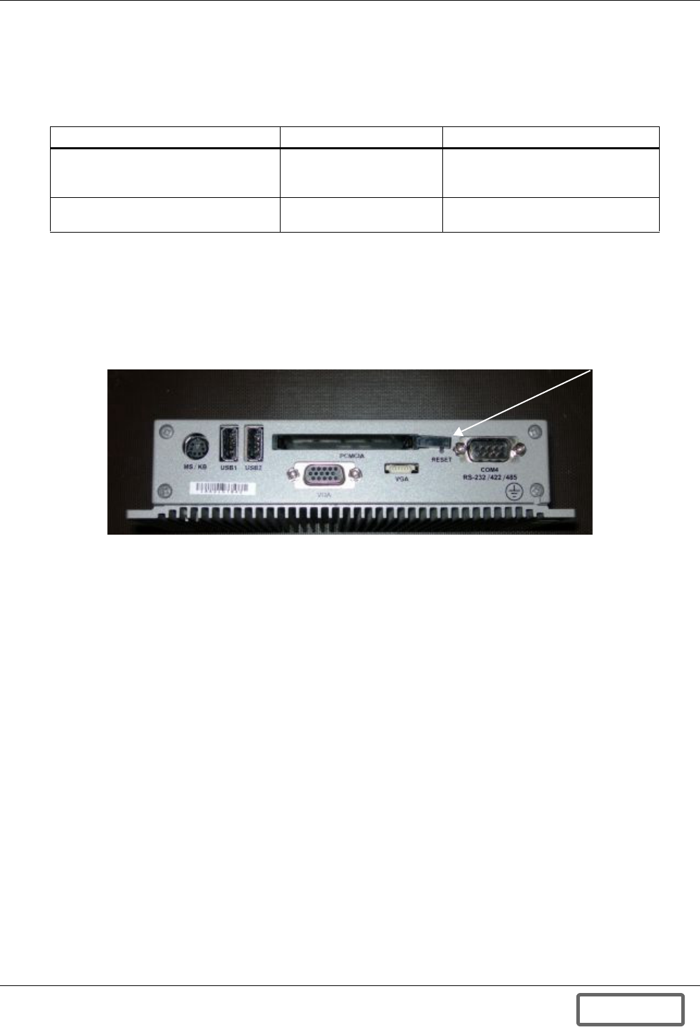
Data Collection Module
106
Appendix B.4 DCM Troubleshooting
Appendix B.4.1 DCM Troubleshooting Principles
There are few circumstances in which the Liebert FS might operate in an unexpected manner. This
section explains a few of these circumstances and offers some solutions to such issues.
Appendix B.4.2 Resetting the DCM
If the DCM requires rebooting, use a small object, such as a paperclip, to press the reset button,
shown in Figure 115. The reset button is marked RST. It is adjacent to the RS-232 COM2 Port. The
DCM will emit a series of beeps if the DCM is reset. Allow a minimum of 90 seconds for a complete
reboot before attempting to connect to the DCM.
Figure 115 Data Collection Module reset button
Table 33 Troubleshooting
What You See… What It Means… What To Do…
A gray windows appears in the Web
browser when connecting to the DCM
The HTML page is not
loading properly
Ensure that the correct IP address is
entered and or check with IT
administrator
Cannot connect to specified address The DCM is not online or
connect to the network
Verify that the Ethernet cable is
securely connected to the DCM
Reset Button
DISCONTINUED
PROD UC T
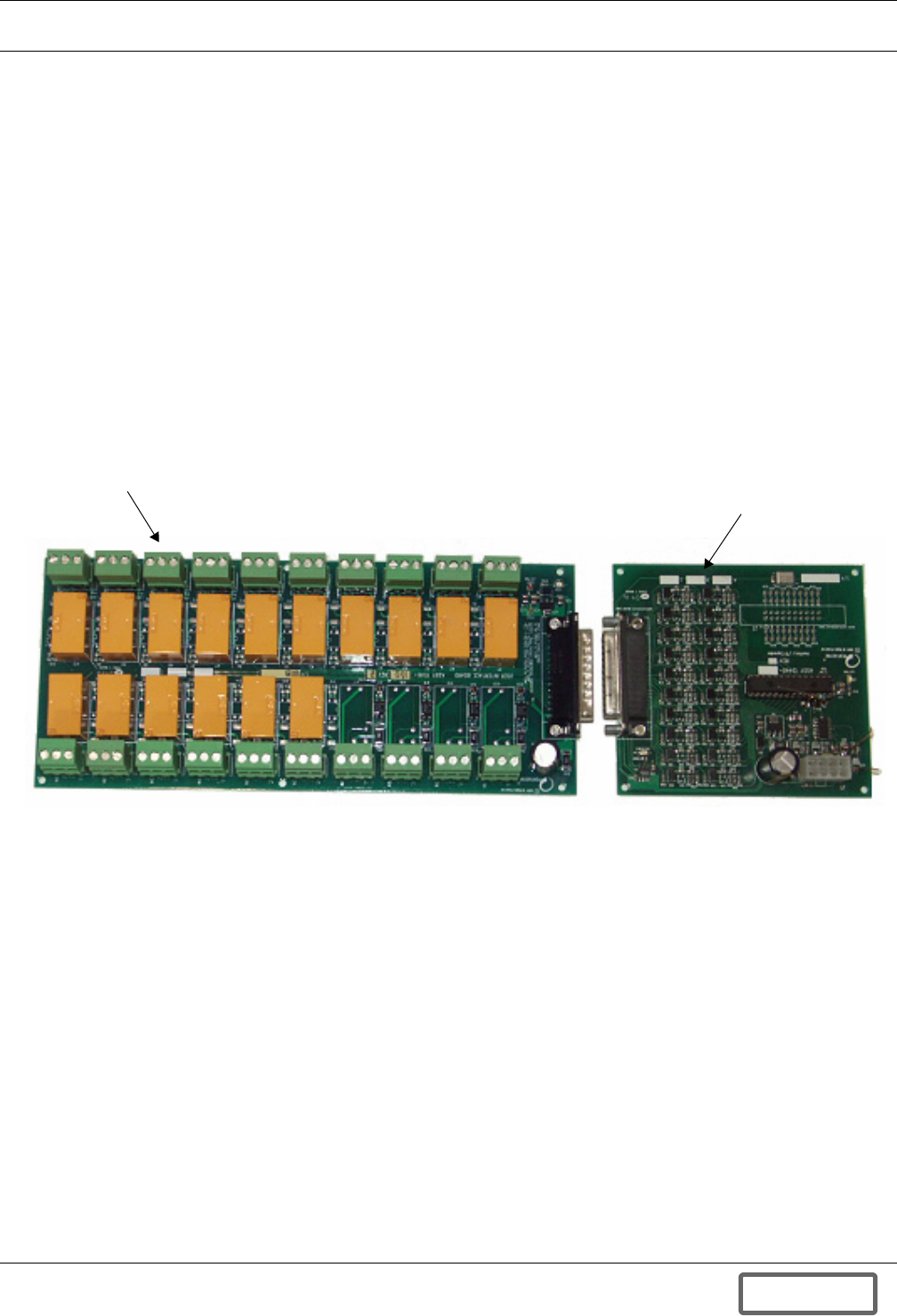
Versatile Interface Board
107
APPENDIX C.0VERSATILE INTERFACE BOARD
Appendix C.1 General Information—Versatile Interface Board
Appendix C.1.1 Versatile Interface Board Overview
The Versatile Interface Board (VIB) is designed to provide real-time status feedback and control of
the Liebert FS. The VIB has 16 digital outputs (isolated, dry Form C contacts) and three digital
inputs (optical isolator) that provide the user with information about the operational mode and state
of charge of the Liebert FS, as well as the ability for the user to start the system, stop the system and
clear alarms.
The VIB consists of the following components:
• 12578 - Auxiliary I/O Interface Board
• 11516 - User Interface Board (UIB)
• 12781 - Cable Assembly
• Mounting hardware
Figure 116 shows the two main electrical components of the VIB.
Figure 116 VIB components
P/N 11516
P/N 12578
DISCONTINUED
PROD UC T

Versatile Interface Board
108
Appendix C.1.2 VIB Features
The VIB provides fully isolated inputs and outputs that operate on a wide range of voltages for maxi-
mum flexibility. Each I/O is programmed to perform a dedicated function. The specific function of
each I/O is listed below in Table 34.
For reference, the I/O designations are shown in Figure 117. The number of each I/O is also labeled
on the circuit board.
Table 34 VIB I/O functions
I/O Interface VIB Designation Description
1 Output 1 Off1Mode = Off (RPM < 200)
2 Output 2 Startup Mode = Startup (200 < RPM < 25000)
3 Output 3 Charge Mode = Charge (RPM > 25000)
4 Output 4 SOC >= 0% State of Charge >= 0%
5 Output 5 SOC >= 12.5% State of Charge >= 12.5%
6 Output 6 SOC >= 25% State of Charge >= 25%
7 Output 7 SOC >= 37.5% State of Charge >= 37.5%
8 Output 8 SOC >= 50% State of Charge >= 50%
9 Output 9 SOC >= 62.5% State of Charge >= 62.5%
10 Output 10 SOC >= 75% State of Charge >= 75%
11 Output 11 SOC >= 87.5% State of Charge >= 87.5%
12 Output 12 Ready Mode = Ready (SOC >= 99%)
13 Output 13 Discharge Mode = Discharge
14 Output 14 Shutdown Mode = Shutdown
15 Output 15 Warning Mode = Warning
16 Output 16 Fault Mode = Fault
17 Input 1 Start2Start Command Issued
18 Input 2 Shutdown2Shutdown Command Issued
19 Input 3 Clear Fault Clear Fault Command Issued
20 Output 17 Rotor Temp Rotor Temp High
1. The “OFF” signal is also used to indicate if the temperature of the rotor is too warm. If the “OFF” output is asserted while any
of the other “Mode” outputs are asserted (STARTUP, CHARGE, SHUTDOWN, DISCHARGE) or while the State of Charge is
>= 0%, then the rotor is too warm and must cool before charge resumes.
2. “START” and “SHUTDOWN” inputs are mutually exclusive. If they are asserted simultaneously, both will be ignored.
DISCONTINUED
PROD UC T
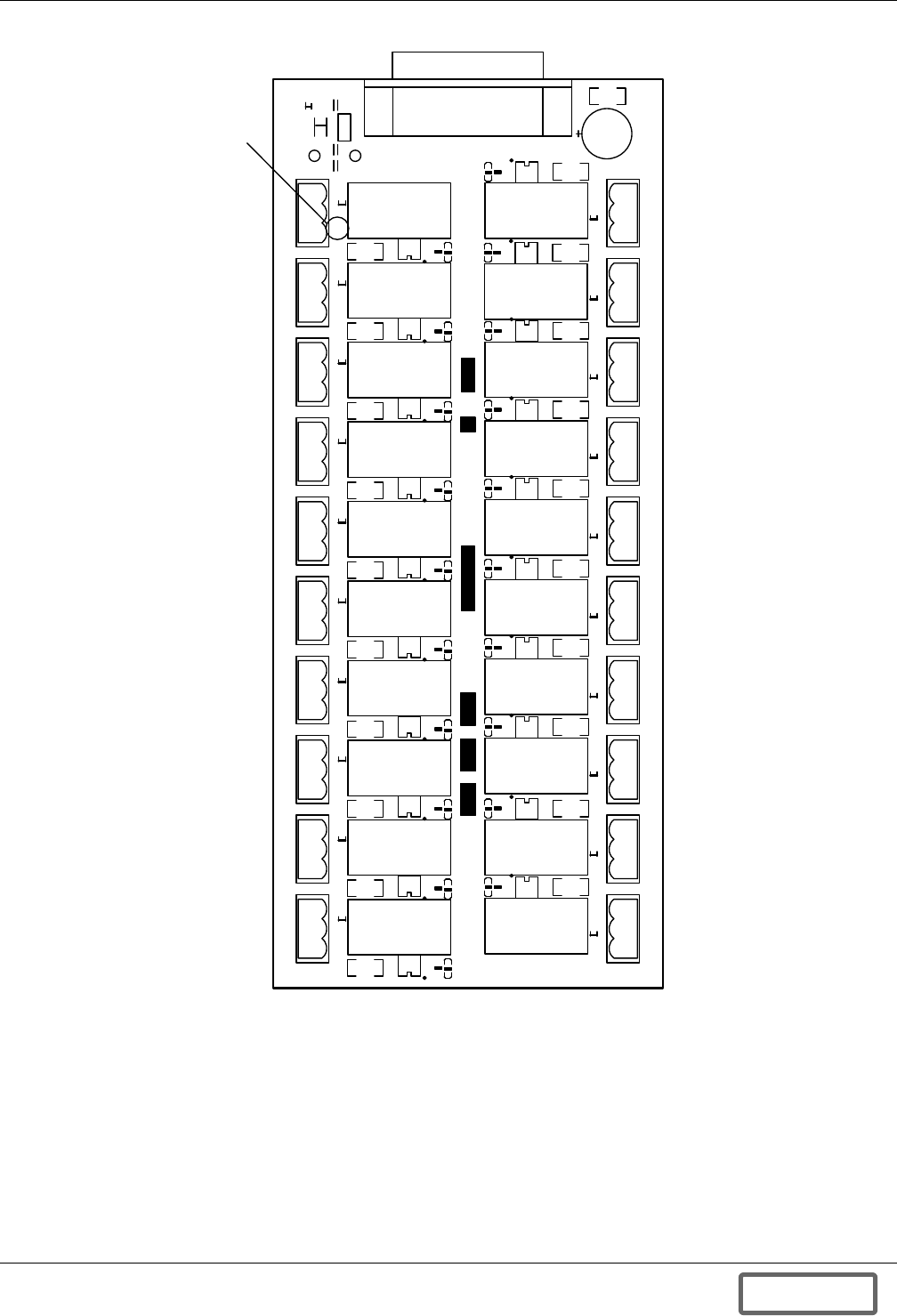
Versatile Interface Board
109
Figure 117 I/O Designations
I/O Label
(X20)
~
I /O 2
I/ O 3
I/ O 4
I/ O 5
I /O 6
I /O 7
I /O 8
I /O 9
I/O 10
COM
N.C.
W/N.O.
COM
N.C.
W/N.O.
COM
N.C.
W/N.O.
COM
N.C.
W/N.O.
COM
N.C.
W/N.O.
COM
N.C.
W/N.O.
COM
N.C.
W/N.O.
COM
N.C.
W/N.O.
COM
N.C.
W/N.O.
COM
N.C.
W/N.O.
COM
N.C.
W/N.O.
COM
N.C.
W/N.O.
COM
N.C.
W/N.O.
COM
N.C.
W/N.O.
COM
N.C.
W/N.O.
COM
N.C.
W/N.O.
COM
N.C.
W/N.O.
COM
N.C.
W/N.O .
COM
N.C.
W/ N . O .
COM
N.C.
W/N .O .
USER INTERFACE BOARD ASSY 11518-- REV
~
~
~
~
~
~
~
~
~
~
~
~
~
~
~
~
~
~
~
~
I /O1 1
I /O1 2
I /O1 3
I /O1 4
I /O1 5
I /O1 6
I /O1 7
I /O1 8
I /O1 9
I /O2 0
xxxx
Xxxxxxxxxx xxxxx xxxxxxx
xxxxx xxxxx xxxx xxxx xxxxxx
xx x xxxx xxxxx xx x xxxxxx
xxxxxxxx xxx xxxxx xxxxxxx xx
LIEBERT
XXXXX XXXXX XXX
S/N A B C
I /O 1
I/O 11
I/O 13
I/O 12
I/O 14
I/O 15
I/O 16
I/O 17
I/O 8
I/O 19
I/O 20I/O 1
I/O 3
I/O 2
I/O 4
I/O 5
I/O 6
I/O 7
I/O 8
I/O 9
I/O 10
DISCONTINUED
PROD UC T
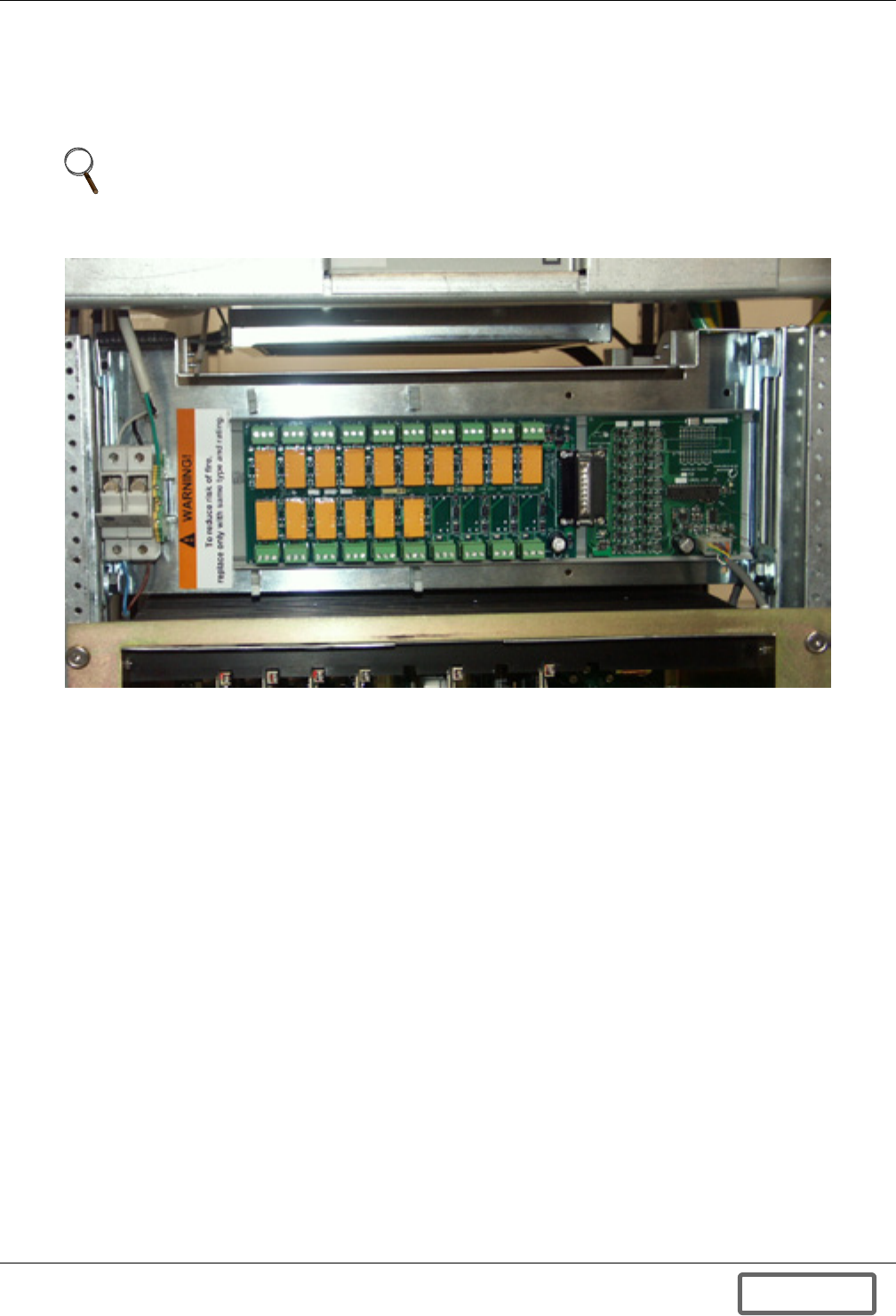
Versatile Interface Board
110
Appendix C.2 VIB Installation and Configuration
Appendix C.2.1 VIB Installation
The VIB has been installed behind the service panel of the Liebert FS. The power/communications
cable has been connected to the Main Control Module at the factory.
Figure 118 Versatile Interface Board mounted in the Liebert FS
Appendix C.2.2 VIB Requirements
The VIB requires software version 2.09 or later to operate properly. To verify the software version,
press F6 from the main screen of the display panel. The software version is displayed in the lower left
corner of the display. Press F6 when finished.
Appendix C.2.3 VIB Input Specifications
• Opto-isolated inputs, active high.
• Minimum Trigger Voltage: 3.5V DC (“IN” relative to “COM”).
• Maximum Operating Voltage: 32V DC (“IN” relative to “COM”).
• Minimum Input Current: 5mA DC.
• Inputs must be present for at least 200ms to be recognized as valid signals.
• Each input has a green status LED to indicate assertion of the signal.
Appendix C.2.4 VIB Output Specifications
• Dry contact Form C relay: Normally Open (NO), Normally Closed (NC) and Common (COM) out-
puts available.
• Maximum Contact Resistance: 50mΩ
• Minimum Insulation Resistance: 100MΩ at 500V DC
• Maximum Switching Power: 500VA, 90W
• Maximum Switching Voltage: 250V AC, 30V DC
• Maximum Switching Current: 2A AC, 3A DC
• Minimum Life: 100,000 operations on resistive loads
• Each output has a green status LED to indicate assertion of the signal
NOTE
If The VIB option has been purchased separately, refer to the installation instructions included
with the kit for the proper mounting procedure.)
DISCONTINUED
PROD UC T
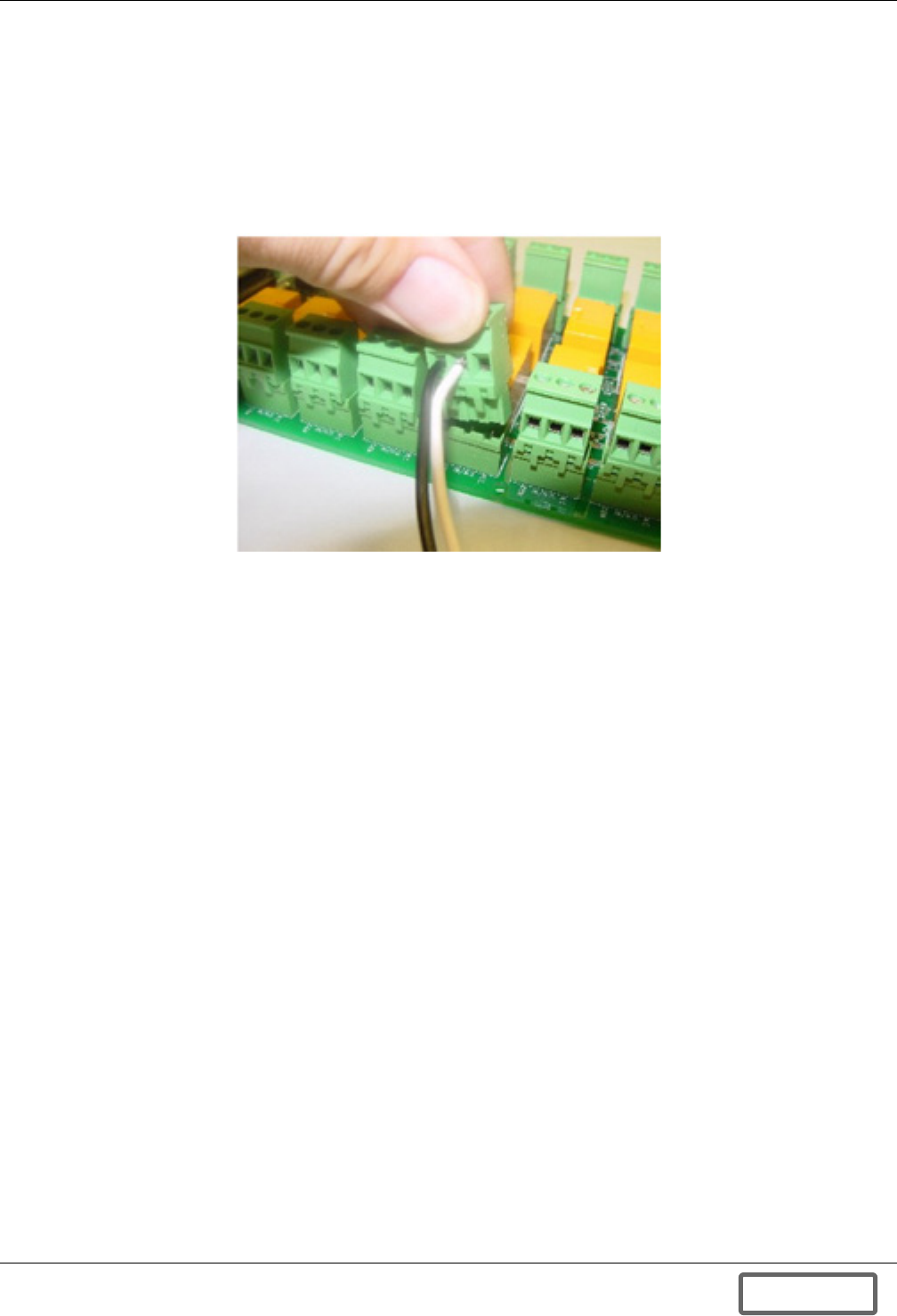
Versatile Interface Board
111
Appendix C.2.5 VIB Connections
The VIB is supplied with removable screw-terminal connectors to allow for easy integration
Figure 119. The user must supply the wire as specified below to make the connections to the VIB
connectors.
• Wire gauge: 12-24 AWG
• Stripped length: 0.125" - 0.250"
• Tightening torque: 4.4 inch-pounds (maximum)
Figure 119 VIB screw terminal connections
Appendix C.3 VIB Operation
Upon Initial System Startup of the Liebert FS by a Liebert-certified service technician, your VIB will
be operational. There is nothing to turn on or configure. Make sure that all external connections to
the VIB are made with the Liebert FS power off. Making connections while power is applied may have
undesirable effects and may damage the equipment.
Appendix C.3.1 VIB Operational States
The operational status of the VIB is indicated on the main screen of the Display Panel. There are
three possible states: “Enabled”, “Disabled” and “Not Available”. They are indicated on the Display
Panel by “1,” “0” or “NA,” respectively.
“Enabled” State
If the VIB is detected when the system is powered-up or rebooted, it will automatically be enabled. If
for any reason the VIB has been disabled, it can be re-enabled by pressing F6 (Setup Parameters),
then F3 (UIB Enable). While the VIB is enabled, the “Start,” “Stop” and “Clear Fault” buttons will not
be visible on the Display Panel. To control the Liebert FS from the Display Panel, the VIB must first
be disabled.
“Disabled” State
If the VIB is not detected when the system is powered-up or rebooted, it will automatically be dis-
abled. At any time during operation the VIB can be disabled by pressing F6 (Setup Parameters), then
F3 (UIB Disable). When the VIB is disabled, the inputs are ignored and all outputs are turned off.
Before disabling the VIB, consider how disabling the board will affect other system components.
“Not Available” State
The Liebert FS continually monitors the status of the VIB to verify that it is operating correctly. If the
response from the VIB is not what is expected by the Liebert FS, “WARNING” will be displayed on
the front panel.
DISCONTINUED
PROD UC T

Versatile Interface Board
112
Appendix C.4 Troubleshooting the VIB
Appendix C.4.1 UIB State Not Displayed on the Front Panel
• Check that no other faults are present on the display panel.
• Call Liebert for instructions on how to enable the VIB functionality.
Appendix C.4.2 VIB in “Disabled” or “Not Available” State
• Attempt to enable the VIB by pressing F6 (Setup Parameters), then F3 (UIB Enable).
• Verify that the cable to the VIB is plugged in properly.
• Verify power is present on the Auxiliary I/O board. This is indicated by illumination of LED
“LD2”.
• Verify power is provided to the UIB. This is indicated by illumination of “LD1” on the Auxiliary
I/O board and “LD21Pentagon on the UIB. Note that “LD2”on the Auxiliary I/O board will be illu-
minated only if the UIB is connected.
• Check the continuity of the cable from pin to pin.
Appendix C.4.3 Inputs Not Recognized
• Verify power is present at the VIB.
• Verify the VIB is enabled on the display panel.
• Verify that the proper voltage is being supplied to the input.
• Verify that the LED indicator corresponding to the input illuminates when the input signal is
applied.
Appendix C.4.4 Outputs Not Asserted
• Verify power is present at the VIB.
• Verify the VIB is enabled on the display panel.
• Verify that the LED indicator corresponding to the output illuminates when the output is
asserted.
DISCONTINUED
PROD UC T
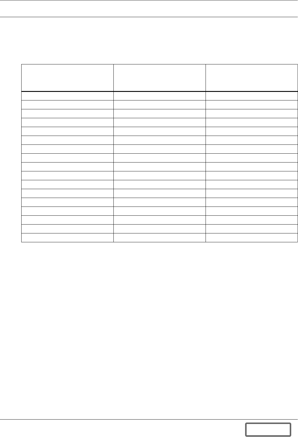
Installation Drawings
113
APPENDIX D.0INSTALLATION DRAWINGS
Appendix D.1 Liebert FS Flywheel Submittal Document Matrix
Following is a list of submittal documents that must accompany each Liebert FS that ships from the
factory. The documents are grouped by Liebert FS model number.
Table 35 Submittal documents accompanying Liebert FS
Liebert FS Model Number:
25FS19ES0000; Liebert
Series 300 Flywheel
Storage Solution
Liebert FS Model Number:
37FS19ES0000; Liebert
NPower Flywheel
Storage Solution
Liebert FS Model Number:
39FS19ES0000; Liebert Series
610/600T/
600 Flywheel Storage Solution
12-100120-00 12-100120-00 12-100120-00
12-100120-02 12-100120-01 12-100120-03
12-100120-08 12-100120-08 12-100120-04
12-100120-09 12-100120-09 12-100120-08
12-100120-10 12-100120-10 12-100120-09
12-100120-11 12-100120-11 12-100120-11
12-100120-12 12-100120-12 12-100120-12
12-100120-13 12-100120-13 12-100120-13
12-100120-14 12-100120-14 12-100120-14
12-100120-16 12-100120-16 12-100120-16
12-100120-17 12-100120-17 12-100120-17
12-100120-18 12-100120-18 12-100120-18
12-100120-20 12-100120-19 12-100120-20
12-100120-21 12-100120-20 12-100120-21
12-100120-22 12-100120-21 12-100120-22
Control_WL_S300 12-100120-22 Control_WL_S610
— Control_WL_NPower —
DISCONTINUED
PROD UC T
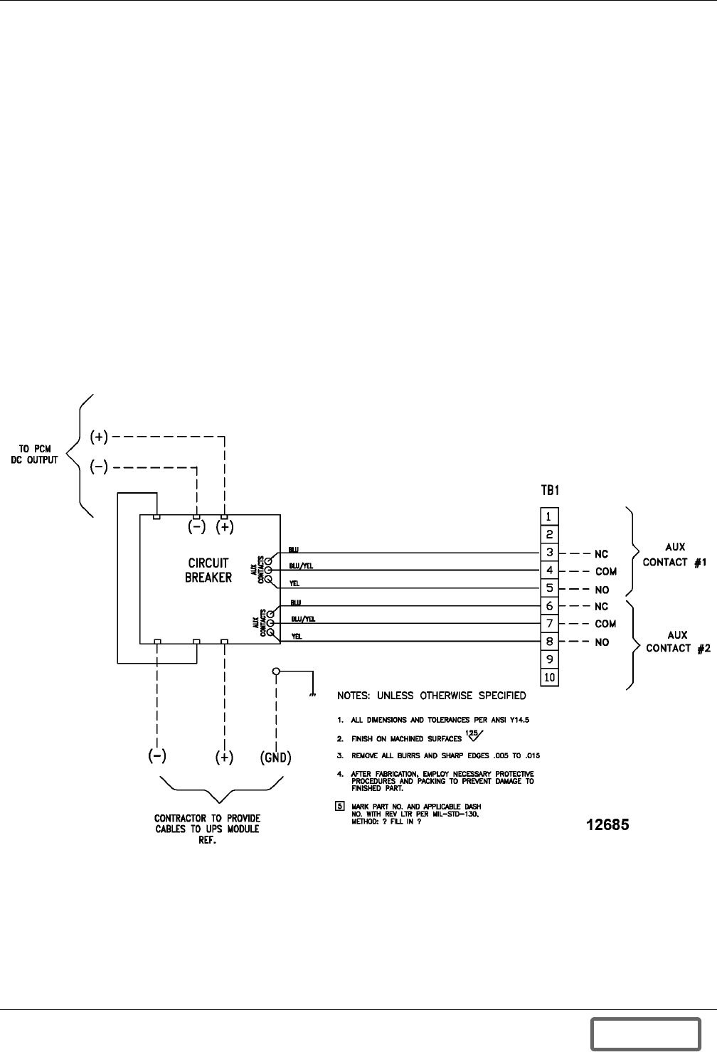
Installation Drawings
114
Appendix D.2 Other Liebert FS Drawings
Following is a list of additional Liebert FS drawings that are available for distribution. These draw-
ings are not directly linked to any specific Liebert FS model number, because most of them are appli-
cable to Liebert FS cabinets connected in parallel and we do not have a unique model number to
identify such units.
Parallel Liebert FS Cabinets – Two - Three Cabinets, no DC Junction Box
• 12-100120-04 – Control Wiring, Liebert Series 610, 600T, 600, 300
• 12-100120-14 – One Line Diagram
• 12-100120-10 – Control Wiring, Paralleled Units
• 12-100120-20 – One Line Diagram, Paralleled Units
Parallel Liebert FS Cabinets – Four-Eight Cabinets with DC Junction Box
• 12-100120-17 – One Line Diagram
• 12-100120-10 – Control Wiring, Paralleled Units
• 12-100120-20 – One Line Diagram, Paralleled Units
Single Liebert FS Cabinets – Additional Elevation Drawings
• 12-100120-11 – Liebert FS Custom Configuration without Circuit Breaker
Figure 120 No UVR, circuit breaker to terminal block wiring
Note: PCM is UPS module.
DISCONTINUED
PROD UC T
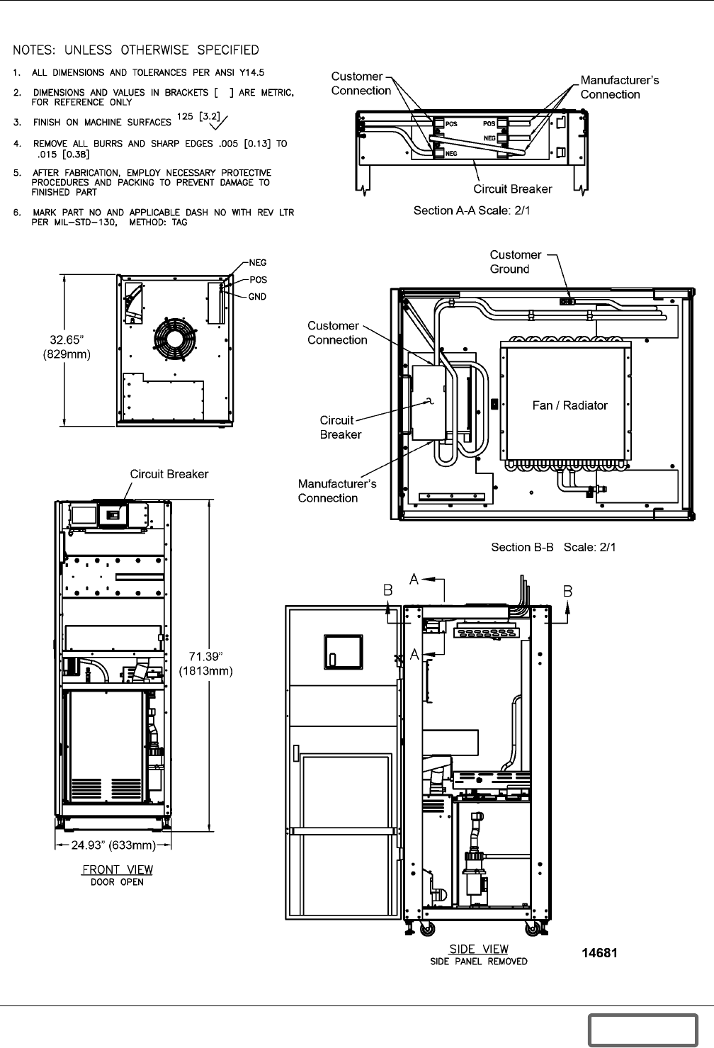
Installation Drawings
115
Figure 121 Electrical connections
DISCONTINUED
PROD UC T
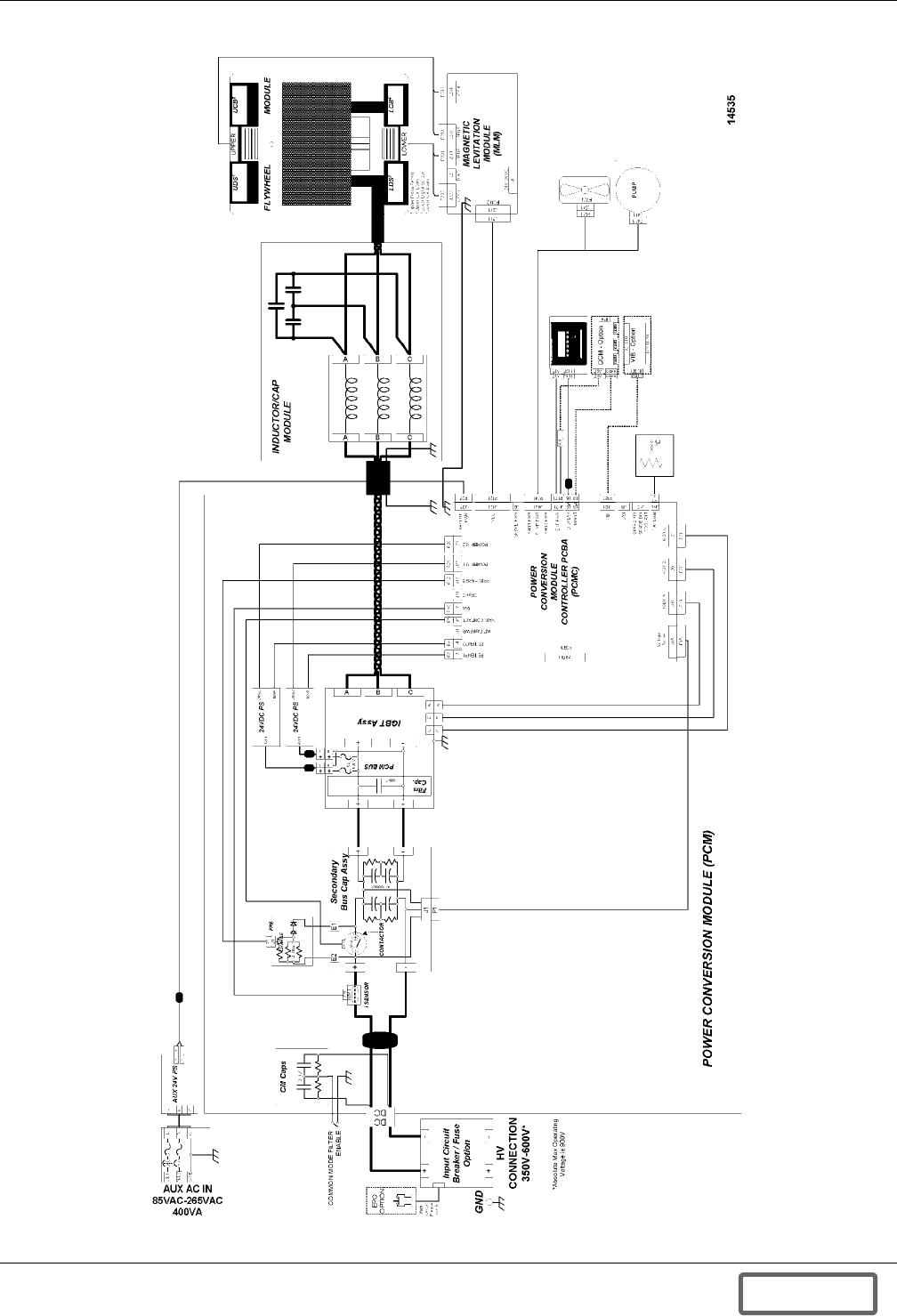
Installation Drawings
116
Figure 122 Electrical system block diagram
DISCONTINUED
PROD UC T
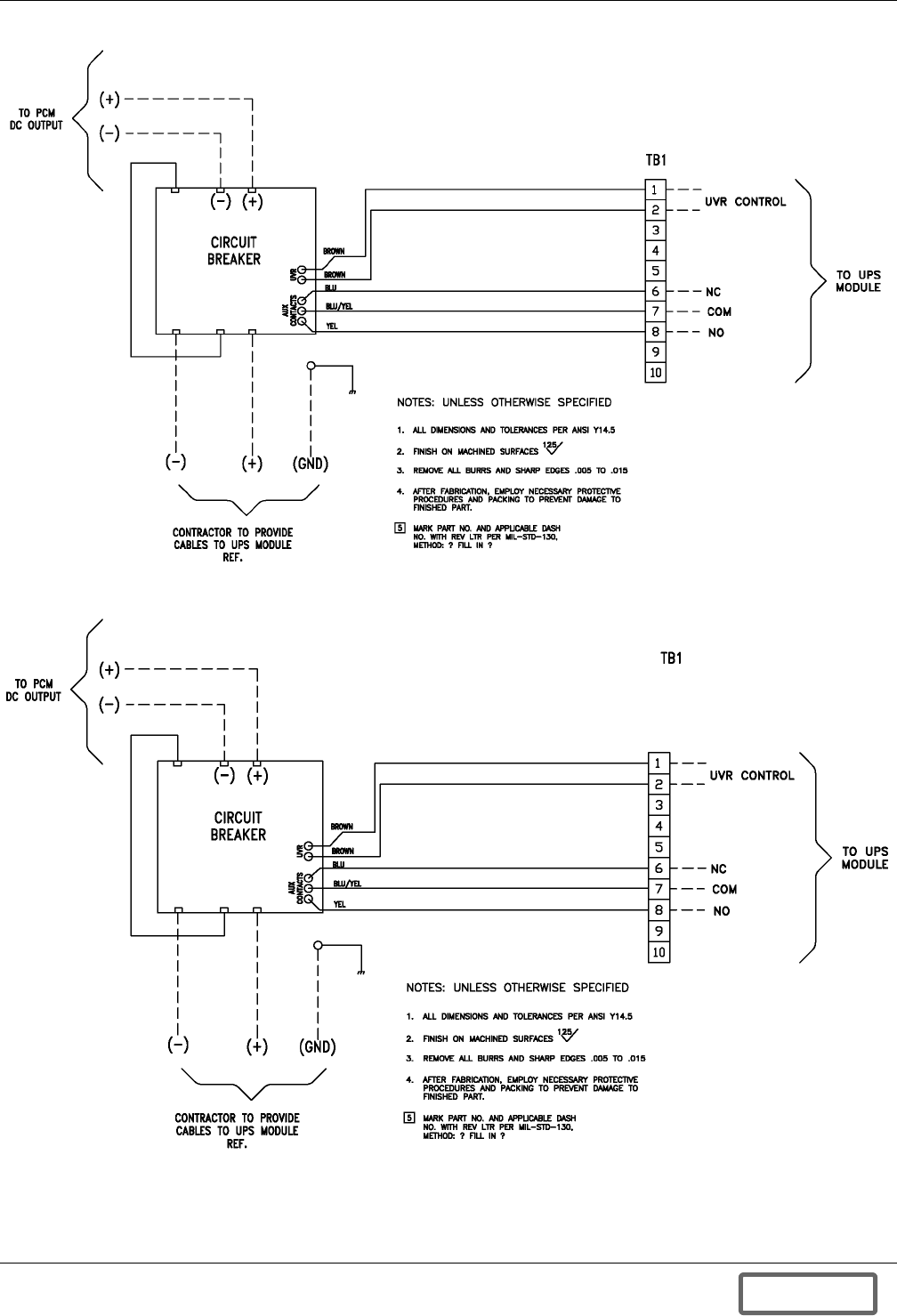
Installation Drawings
117
Figure 123 24 UVR, circuit breaker to terminal block wiring
Figure 124 48 UVR, circuit breaker to terminal block wiring
Note: PCM is UPS module.
12-100120-16
Rev. 0
Note: PCM is UPS module.
12-100120-16
Rev. 0
DISCONTINUED
PROD UC T
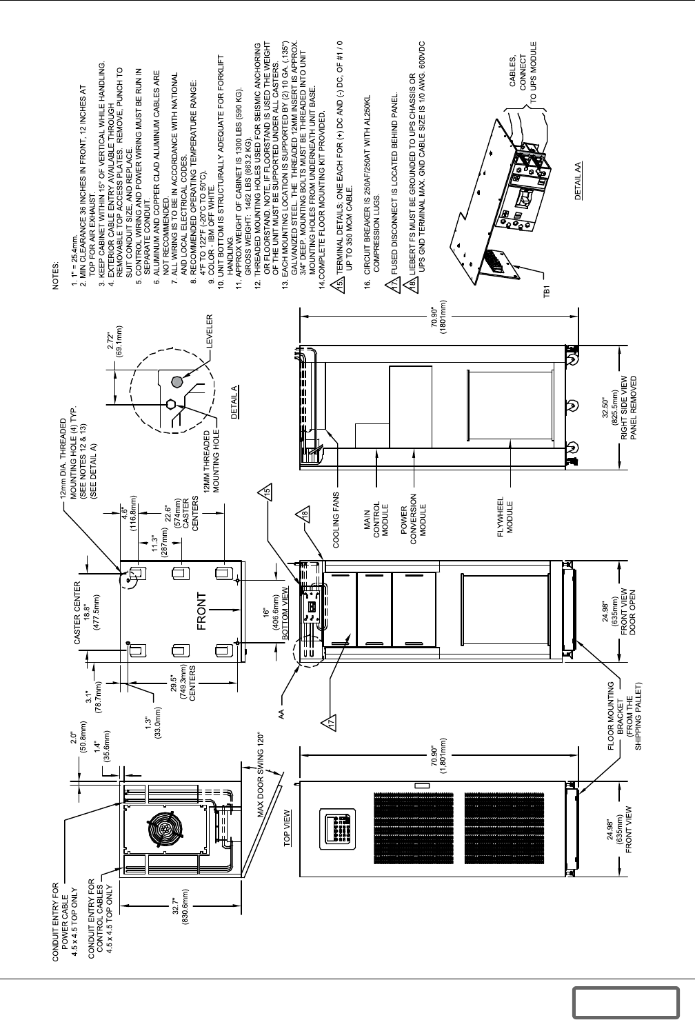
Installation Drawings
118
Figure 125 Outline drawing, Liebert FS cabinet
12-100120-00
Rev. 01
DISCONTINUED
PROD UC T
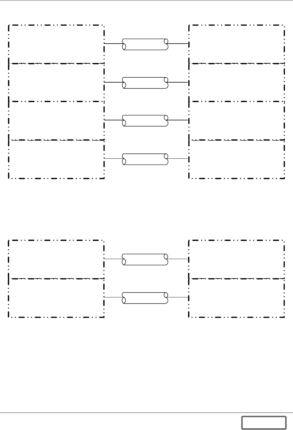
Installation Drawings
119
Figure 126 Control wiring, external interconnect diagram—Liebert FS cabinet to Liebert Npower UPS
module
Figure 127Control wiring external interconnect—Liebert FS to Liebert Series 300
C.G. #17
C.G. #19
Liebert FS Liebert Npower
UPS Module
12-100120-01
Rev. 01
FUSED
DISCONNECT
Provided by others;
120V, 60Hz AC, 400VA
UPS-Protected
Aux. Control Power
C.G. #116
TB1 TB69
C.G. #18
TB7 TB70
TB6 TB73
C.G. #29
Liebert FS Liebert Series 300
UPS Module
12-100120 -02
Rev. 01
FUSED
DISCONNECT
Provided by others;
120V, 60Hz AC, 400VA
UPS-Protected
Aux. Control Power
C.G. #116
TB1 IL -TB1
DISCONTINUED
PROD UC T
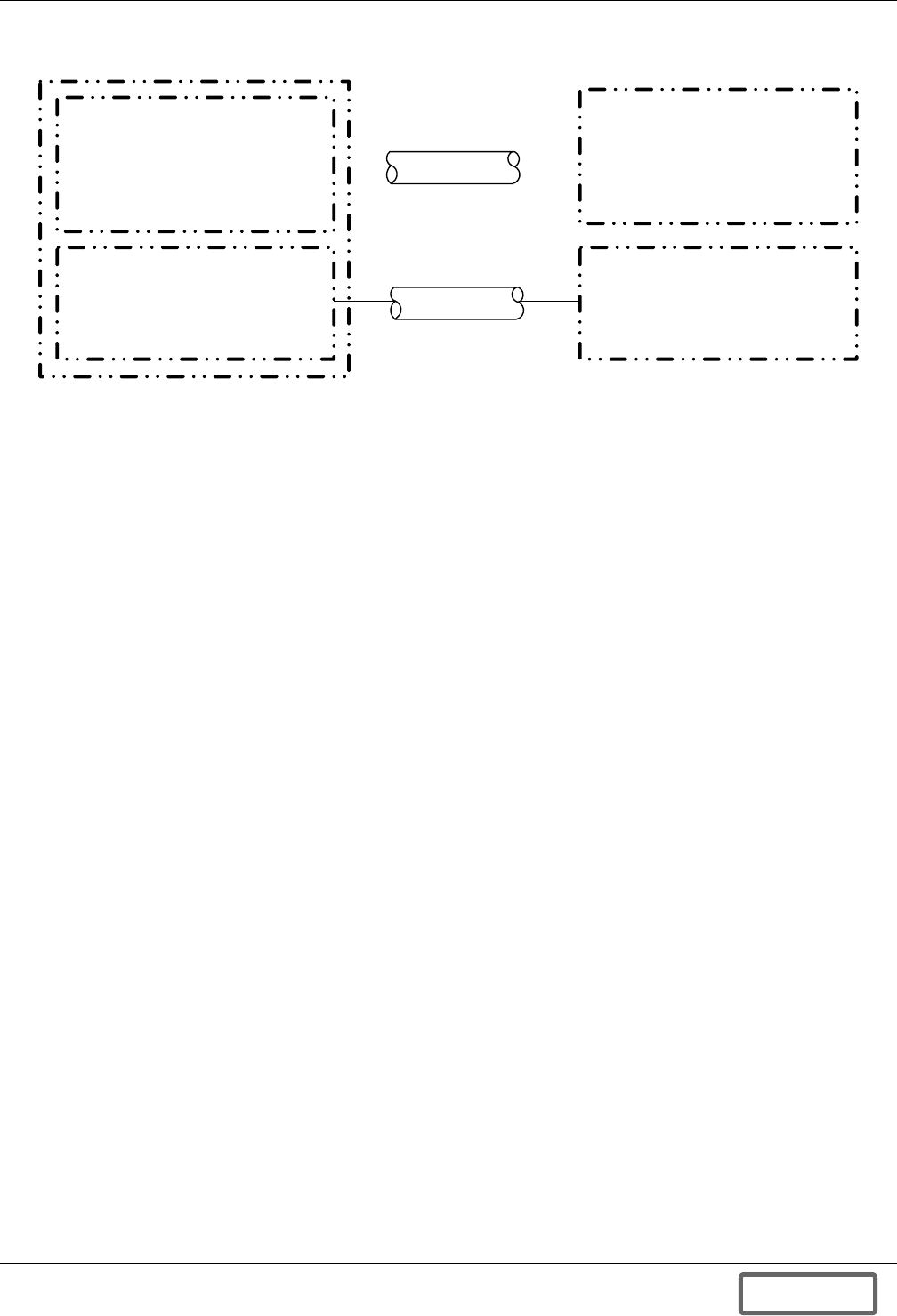
Installation Drawings
120
Figure 128Control wiring—external interconnect diagram, Liebert FS cabinet to Liebert Series 610 UPS
module
Liebert FS Liebert Series 610
UPS Module
12-100120-03
Rev. 01
FUSED
DISCONNECT
Provided by others;
120V, 60Hz AC, 400VA
UPS-Protected
Aux. Control Power
C.G. #116
I1-TB1
C.G. #16
TB1
DISCONTINUED
PROD UC T
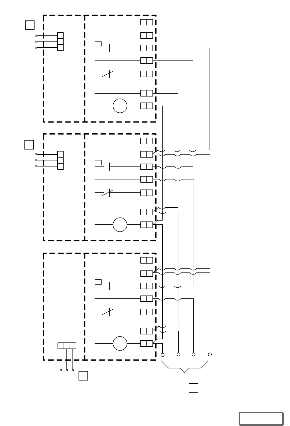
Installation Drawings
121
Figure 129 Control wiring—external interconnect diagram, Liebert FS cabinet to Liebert Series 610 UPS module
10
10
1 2 3
9
9
Fused Disconnect
Liebert FS Status/Control
Terminal Block #3
Line
N
3
Gnd
10
10
9
9
Fused Disconnect
Liebert FS Status/Control
Terminal Block #2
3
1 2 3
Line
N
Gnd
TB1
10
10
9
9
6
6
Fused Disconnect
Liebert FS Status/Control
Terminal Block #1
Line
3
Gnd
N
TB1
1
2
3
UVR
1
1
2
2
8
8
6
6
7
7
1
1
2
2
UVR
TB1
6
6
8
8
7
7
NOTES
1. Minimum available UV coil current must be N times 50mA where N = number of Liebert FS paralleled units.
2. 16AWG - 600VDC (minimum) wires to be provided and installed by custom er or installation contractor.
3. Contact closed when circuit breaker is closed.
4. Series 600/610 can power a total of three UVRs maximum in any combination of FS units, plus module
battery disconnect switches.
5. UPS-protected 1PH AC source recommended. See Section 2.4.4 in user manual.
12-100120-04
Rev. 01
Aux
UVR
To UPS
1
1
2
2
UVR
8
8
7
7
5
4
5
5
DISCONTINUED
PROD UC T

Installation Drawings
122
Figure 130Elevation drawing, Liebert FS cabinet with shipping package
12-100120-08
Rev. 01
48"
(1219mm)
4.4"
(112mm)
45"
(1143mm)
24"
(610mm)
Shipping
Support
Bands
(on either
side)
54"
(1372mm)
76.9"
(1953mm)
Front View Right Side View
Weight, unit only: 1300 lb (590kg)
Shipping Weight: 1462 lb (663kg)
Metal Support
Plates (one on
either side)
Retain -These
are the floor
mounting
brackets
6"
(1219mm)
DISCONTINUED
PROD UC T

Installation Drawings
123
Figure 131Elevation drawing—Liebert FS cabinet
70.9"
(1801mm)
25"
(635mm)
Front
Top
Bottom
32.5"
(826mm)
Right Side
Standard Upgraded
Interactive Display
12-100120 -09
Rev. 1
DISCONTINUED
PROD UC T

Installation Drawings
124
Figure 132Control wiring diagram, Liebert FS power rack system in parallel for capacity
12-100120-10
Rev. 01
FS
200
FS 200
Cabinet
Unit 1
FS 200
Cabinet
Unit 1
FS 200
Cabinet
Unit 2
FS 200
Cabinet
Unit 3
FS 200
Cabinet
Unit N FS
200
FS
200
FS
200
FS 200
Cabinet
Unit 2
FS 200
Cabinet
Unit 3
FS 200
Cabinet
Unit N
DISCONTINUED
PROD UC T

Installation Drawings
125
Figure 133Liebert FS cabinet with optional power terminal block
12-100120-11
Rev. 01
Optional Power
Terminal Block
(shown without cover)
Motor and
Bearing
Controller
Module
Power
Conversion
Module
Ground Strap
Liebert
Module
Fans NEG
GND
POS
NEG
GND
POS
To p Vi e w
24.98" (635mm)
Front View
Door Open
Bottom
View 32.5" (825.5mm)
Right Side View
Panel Removed
70.9"
(1801mm)
DISCONTINUED
PROD UC T

Installation Drawings
126
Figure 134Liebert FS cabinet mechanical installation
Do Not
Tighten
Half-Size View
of Floor Anchor
Rear Mount
12-100120-12
Rev. 01
32-5”
(825.5mm)
Right-Side View
36” (914mm)
Minimum
Front Clearance
12” (305mm) Overhead Clearance
Weight: 1300 lb. (589.6kg)
.5"
(12.7mm)
25”
(635mm)
Front View
Standard
Interactive Liquid
Crystal Display
DISCONTINUED
PROD UC T

Installation Drawings
127
Figure 135Elevation drawing—Liebert FS cabinet with integrated circuit breaker
12-100120-13
Rev. 01
Factory-Integrated
Circuit Breaker
(shown without cover)
Motor
and Bearing
Controller
Module
Power
Conversion
Module
Ground Strap
Liebert
FS Module
Fans
NEG
GND
POS
NEG
GND
POS
Top View
24.98" (635mm)
Front View
Door Open
Bottom
View
70.9"
(1801mm)
32.5" (825.5mm)
Right Side View
Panel Removed
DISCONTINUED
PROD UC T

Installation Drawings
128
Figure 136One-line drawing, three Liebert FS systems in parallel configuration
Bi-Directional
Power Converter
FLYWHEEL
Normally
Open
Factory-Integrated
Circuit Breaker
1
FLY WHEE L
Normally
Open
Factory-Integrated
Circuit Breaker
1
FLY WHEE L
Normally
Open
Factory-Integrated
Circuit Breaker
1
InverterRectifier
Liebert FS (1) Liebert FS (2) Liebert FS (3)
Battery/Usage
(optional)
Battery/DC In
Liebert FS
Systems
in Parallel
3
Out
Bi-Directional
Power Converter
When parallel, all DC power cables must be identical in length, ± 10%.
1
12-100120-14
Re v. 01
Liebert UPS Module
3
In
Bi-Directional
Power Converter
DISCONTINUED
PROD UC T

Installation Drawings
129
Figure 137Control wiring diagram—Liebert FS cabinet - manually operated circuit breaker
1
3
3
4
5
6
7
8
9
10
(+)
(-)
(+)(-) (GND)
To Liebert FS
PCM DC Output
NOTE
1. PCM – Power Conversion Module
TB1
UVR Control
NC
NO
COM
To Liebert
UPS Module
12-100120-16
Rev. 01
UVR Aux.
Contacts
Liebert FS
Circuit
Breaker
Blu
Brown
Brown
Blu/Yel
Yel
Contractor to Provide Cables
To Liebert UPS Module
DISCONTINUED
PROD UC T

Installation Drawings
130
Figure 138One-line diagram—Liebert FS systems with factory-integrated circuit breakers with Liebert UPS
module
Bi-Directional
P ower Co nve rte r
NOTES
1. Npower: 2-8 units in parallel without requiring a DC
disconnect switch.
2. Series 610/600 2-3 units in parallel without requiring a DC
disconnect switch. It can power a total of three UVRs
maximum in any combination of FS units, plus module
battery disconnect switches.
Liebert FS
Systems
in Parallel
3
Out
Liebert UPS Module
When parallel, all DC power cables
must be identical in length, ± 10%
1
Liebert FS (N)
InverterRectifier
DC Junction Box
Battery/Usage
(optional)
12-100120-17
Rev. 01
3
In
F L Y W HE EL
Normally
O pe n
Circuit Breake r
1
Bi-Directional
Power Converter
Liebert FS (3)
FLYWHEEL
Normally
Ope n
Circu it Br ea ker
1
Bi-Directional
Po wer Con verter
Liebert FS (2)
FLY WHEE L
Normally
Op en
Circuit Breaker
1
Bi-Directional
P ower Co nve rte r
Liebert FS (1)
FLYWHEEL
Normally
Op en
Circuit Breaker
1
DISCONTINUED
PROD UC T

Installation Drawings
131
Figure 139 One-line diagram—single Liebert FS system with factory-integrated circuit breaker supplying
Liebert UPS module
Battery/DC In
Liebert FS
System
12-100120 -18
Rev. 0
Liebert UPS Module
FLYWHEEL
Normally
Open
Circuit Breaker
Rectifier Inverter
3
Out
3
In
Battery/Usage
(optional)
Bi-Directional
Power Converter
DISCONTINUED
PROD UC T

Installation Drawings
132
Figure 140Control wiring diagram—Liebert FS - optional electrically operated circuit breaker Liebert
Npower units
T B3
TB1
TB2
TB5 TB9
P2
TB8
400
401
113 Therm (In )
114 ( Ther m (Out )
Contractor to Provide Cables
to Liebert UPS Module
Yellow
Blue/Yellow
Blue
Br own
Br own
(-)
(-) (+)
(+) (GND)
(-)
(+)
400
401
Liebert FS
Circuit Breaker
To Liebert FS
PCM DC
Output
Moto r Ope r. Po w er
Yellow N .C.
Bl ue /Yel l ow
Blue N .C .
Brown
Brown
12-100120-19
Rev. 0
Note:
1. PCM – Power Conversion Module
101 24 VDC +
102 24 VDC -
103 Control Relay Power
104 Motor Oper . On Signal
105 Motor Oper . Off Signal
106 N.O.
109 Logic GND
113 Therm (In)
114 Therm (Out )
112 (-)
110 (+ )
108 N.C .
107 Common
TB4 TB6 TB7
Contractor to
Provide
Cables to
Liebert UPS
Module
Breaker Aux.
Contacts
UVR
Control
Aux.
Contacts
UVR
DISCONTINUED
PROD UC T

Installation Drawings
133
Figure 141Two-eight paralleled Liebert FS units with factory-integrated circuit breaker in parallel with a
Liebert UPS
Bi-Directional
P ower Co nve rte r
NOTES
1. Series 610/600 requires the use of MBD for more than
three units in parallel. It can power a total of three UVRs
maximum in any combination of FS units, plus module
battery disconnect switches.
Liebert FS
Systems
in Parallel
3
Out
Liebert UPS Module
When parallel, all DC power cables must be
identical in length, ± 10%.
1
Liebert FS (N)
InverterRectifier
DC Junction Box
12-100120-20
Rev. 01
3
In
F L Y W HE EL
Normally
O pe n
Circuit Br eaker
2
Bi-Directional
Power Converter
Liebert FS (3)
FLYWHEEL
Normally
Ope n
Circu it Br ea ker
2
Bi-Directional
Po wer Con verter
Liebert FS (2)
FLY WHEE L
Normally
Op en
Circuit Breaker
2
Bi-Directional
P ower Co nve rte r
Liebert FS (1)
FLYWHEEL
Normally
Op en
Circuit Breaker
2
2
Battery/Usage
(optional)
Module Battery
Disconnect
2Series 610/600 requires the use of MBD
for more than three units in parallel.
DISCONTINUED
PROD UC T

Installation Drawings
134
Figure 142One-line diagram, single Liebert FS and battery with factory-integrated circuit breaker supplying
Liebert UPS—UPS DC terminal point of common connection
Liebert UPS Module
Rectifier Inverter
3
Out
3
In
Liebert FS
System
Bi-Directional
Power Converter
12-100120 -21
Rev. 0
FLYWHEEL
Normally
Open
Circuit Breaker
VRLA Battery
or
Flooded Battery
DISCONTINUED
PROD UC T

Installation Drawings
135
Figure 143One-line diagram, single Liebert FS and battery with factory-integrated circuit breaker supplying
Liebert UPS—UPS battery point of common connection
Liebert UPS Module
Rectifier Inverter
3
Out
3
In
Liebert FS
System
12-100120 -22
Rev. 0
FLYWHEEL
Normally
Open
Circuit Breaker
VRLA Battery
or
Flooded Battery
Bi-Directional
Power Converter
DISCONTINUED
PROD UC T

Installation Drawings
136
Figure 144 Status/control wiring, multiple units
3
UVR
9
9
8
8
7
7
6
6
5
5
3
3
2
2
10
10
4
4
1
1
End (N) Liebert FS Cabinet
FS Status / Control Terminal Block
3
5
4
Intermediate (1 through N-1) Liebert FS Cabinet
FS Status / Control Terminal Block
3
UVR
9
9
8
8
7
7
6
6
5
5
3
3
10
10
4
4
1
1 2
2
3
5
4
To UPS
AUX
UVR
Notes: Unless Otherwise Specified
1. Minimum UV coil current must be N times 50mA where N = Number of Liebert FS
paralleled units.
2. 16 AWG-600VDC (minimum) wires to be provided and installed by customer or
installation contractor.
3. Contact closed when circuit breaker is closed
4. UVR not available with IKIT-CB1, A05, D01, E01.
5. Available only with IKIT-CB1, A05, D01, E01.
DISCONTINUED
PROD UC T

Installation Drawings
137
Figure 145 Wiring specifications, Liebert FS and Liebert Series 300
Wire
No.
Terminal Designation Signal
Name
Maximum
Voltage
Maximum
Current Color
Wire Size
& Type
Maximum
Length RemarksFrom To
Series 300 UPS - Cable Group # 27 (Flywheel CB IFM) From I1 In UPS Module to TB1 on Liebert FS Module
901 I1-TB1-1 TB1-1 Trip Signal (+) +24 VDC 100mA
1/C #16
(2.5 mm2)
Stranded
500 ft
(150 m)
902 I1-TB1-2 TB1-2 Trip Signal (-) -24 VDC 100mA
903 I1-TB1-7 TB1-7 Aux Comm 24 VDC 100mA
904 I1-TB1-8 TB1-8 Aux N.O. 24 VDC 100mA
Series 300 UPS - Cable Group # 116 Flywheel Aux Power, Customer-Provided to Liebert FS TB1 on Fused Disconnect
914 FBO TB1-1 Line 120VAC 3.5A
1/C #16
(2.5 mm2)
Stranded
500 Ft
(150
Meters)
UPS-
Protected
Auxiliary
Control
Power
915 FBO TB1-2 Neutral 120VAC 3.5A
916 FBO TB1-3 GND 120VAC 3.5A
1. Each cable group must be run in a separate, grounded, rigid metal conduit to prevent control signal interference.
2. Refer to UPS module/Liebert FS control connection diagram for location of wiring connections.
3. All external wires furnished by others.
4. N.O. = Normally Open; N.C. = Normally Closed; Comm = Common; F.B.O. = Furnished By Others, GND = Ground
5. All wiring must be in accordance with national and local electrical codes.
Dwg. No. Control_WL_S300_Liebert-FS Rev. 01
DISCONTINUED
PROD UC T

Installation Drawings
138
Figure 146 Wiring specifications, Liebert FS and Liebert Npower
Wire
No.
Terminal Designation Signal
Name
Maximum
Voltage
Maximum
Current Color
Wire Size
& Type
Maximum
Length RemarksFrom To
Liebert N-Power UPS - Cable Group # 17 (Flywheel CB IFM) From TB69 in UPS Module to TB1 on Liebert FS Module
101 TB69-1 TB1-1 Trip Signal (+) +24 VDC 100mA 1/C #16 (2.5 mm2)
Stranded
1/C #16 (2.5 mm2)
Stranded 500 ft
(150m)
102 TB69-2 TB1-2 Trip Signal (-) -24 VDC 100mA
103 TB69-3 TB1-3 Motor Op Relay 24 VDC 100mA
104 TB69-4 TB1-4 Motor Op On 24 VDC 100mA
105 TB69-5 TB1-5 Motor Op Off 24 VDC 100mA
106 TB69-6 TB1-6 Aux N.O. 24 VDC 100mA
107 TB69-7 TB1-7 Aux Comm 24 VDC 100mA
108 TB69-8 TB1-8 Aux N.C. 24 VDC 100mA
109 TB69-9 TB1-9 Comm 24 VDC 100mA
110 TB69-10 TB1-10 Battery Sense (+) +24 VDC 100mA
112 TB69-12 TB1-11 Battery Sense (-) -24 VDC 100mA
Liebert N-Power UPS - Cable Group # 18 (Flywheel CB IFM) from TB73 in UPS Module to TB6 on Liebert FS Module
Line TB73-1 TB6-1 Motor Op Pwr 120 VAC 100mA 500 FT
(150m)
Neutral TB73-2 TB6-2 Motor Op Neutral N 100mA
Liebert N-Power UPS - Cable Group # 19 (Flywheel CB IFM) From TB70 in UPS Module to TB7 on Liebert FS Module
113 TB70-1 TB7-1 Temp Sensor 24 VDC 100mA 1/C #16 (2.5 mm2)
Stranded
500 ft
(150m)
114 TB70-2 TB7-2 Sensor Return 24 VDC 100mA
Liebert N-Power UPS - Cable Group # 116 Flywheel Aux Power, Customer Provided to Liebert FS TB1 on Fused
Disconnect
Output
A PHS FBO TB1-1 Line 120VAC 3.5A
1/C #16 (2.5 mm2)
Stranded
500 ft
(150m)
UPS-
Protected
Auxiliary
Control
Power
Output
Net FBO TB1-2 Neutral 120VAC 3.5A
Gnd FBO TB1-3 GND 120VAC 3.5A
1. Each cable group must be run in a separate grounded rigid metal conduit to prevent control signal interference.
2. Refer to UPS module/Liebert FS control connection diagram for location of wiring connections.
3. All external wires furnished by others.
4. N.O. = Normally Open; N.C. = Normally Closed; Comm = common; F.B.O. = Furnished By Others, GND = ground
5. All wiring must be in accordance with national and local electrical codes.
Dwg. No. Control_WL_NPower_Liebert-FS Rev. 1
DISCONTINUED
PROD UC T

Installation Drawings
139
Figure 147 Wiring specifications, Liebert FS and Liebert Series 610
Wire
No.
Terminal
Designation Signal
Name
Maximum
Voltage
Maximum
Current Color
Wire Size
& Type
Maximum
Length
Remarks
From To
Liebert Series 610 UPS - Cable Group #16 (Flywheel CB IFM) From I1 in UPS Module to TB1 on Liebert FS Module
901 I1-TB1-1 TB1-1 Trip Signal (+) +24 VDC 100mA
1/C #16 (2.5 mm2)
Stranded
500 Ft
(150 M
902 I1-TB1-2 TB1-2 Trip Signal (-) -24 VDC 100mA
903 I1-TB1-7 TB1-7 Aux Comm 24 VDC 100mA
904 I1-TB1-8 TB1-8 Aux N.O. 24 VDC 100mA
Liebert Series 610 UPS - Cable Group #116 Flywheel Aux Power, Customer-Provided to Liebert FS TB1 on Fused
Disconnect
914 FBO TB1-1 Line 120VAC 3.5A
1/C #16 (2.5 mm2)
Stranded
500 Ft
(150m)
UPS-
Protected
Auxiliary
Power
Control
915 FBO TB1-2 Neutral 120VAC 3.5A
916 FBO TB1-3 GND 120VAC 3.5A
1. Each cable group must be run in a separate, grounded, rigid metal conduit to prevent control signal interference.
2. Refer to UPS module/Liebert FS control connection diagram for location of wiring connections.
3. All external wires furnished by others.
4. N.O. = Normally Open; N.C. = Normally Closed; Comm = common; F.B.O. = Furnished By Others, GND = ground
5. All wiring must be in accordance with national and local electrical codes.
Dwg. No. Control_WL_S610_Liebert-FS Rev. 01
DISCONTINUED
PROD UC T

Installation Drawings
140
Figure 148 Wiring specifications, Liebert FS and Liebert HiPulse, Liebert NXL or Liebert NX
WIRING SPECIFICATIONS FOR THE
LIEBERT FS AND LIEBERT HIPULSE, LIEBERT NXL OR LIEBERT NX
ARE AVAILABLE BY CONTACTING:
Your local Liebert Sales Representative
Your local Liebert Service Representative
Liebert Corp. at 1-800-Liebert (1-800-543-2378
DISCONTINUED
PROD UC T

Installation Drawings
141
Figure 149 Floor mounting template
16"
(406mm)
NOTE: If hole is drilled too deep, backfill to correct
to proper depth.
2.25 (57mm) max.
4X O5/8" (16mm) Mason Drill x 2.00 (51mm) min.
29-1/2"
(749mm)
DISCONTINUED
PROD UC T

Installation Drawings
142
Figure 150 System mounting kit
Drill Template Dwg
1
6
Bolts and Washers come with cabinet
37
4
5
2
8
DISCONTINUED
PROD UC T

Installation Drawings
143
Figure 151 Liebert FS block diagram
OPTI ONAL
CAPACITORS
FILTER
P REC HA RGE B OARD
CAPA CI TO R BANK
FUSE BOA RD
POW ER I NT E RF A CE BOA RD
POWER BLOCK
POWER DISTRIBUTION BOARD
24VDC PO WE R SUPPLY
24VDC PO WE R SUPPLY
POWER CONVERSION MODULE
F I L TE R
AUXILIARY BACKUP
POWER 24V
UPP ER BE ARING COIL
INSUL ATOR UPPE R BE ARING COIL
UNIV ERSAL PO SITIO N SENSO R
S PEE D
ZY
X
Y
X
TEMP.
UNIV ERSAL PO SITIO N SENSO R
INSULATOR LOWER BEARING COIL
LOWER B EARING CO IL
FLY WHEE L MODULE
MCM
BACKPLANE
POW ER CONVE RS ION MODULE
CONTROLLER
A NA LOG AX IAL AXI S CONTROLL ER
Z
A NA LOG RADIAL AX IS CONTROLLER
LOW ER Y
A NA LOG RADIAL AX IS CONTROLLER
LOW ER X
A NA LOG RADIAL AX IS CONTROLLER
UP PER Y
A NA LOG RADIAL AX IS CONTROLLER
UP PER X
MAIN
CONTROL MO DULE
FAN #1 FAN # 2 PUMP
COOLING SYSTEM
UPP ER BE ARING S ENSOR
UPPE R BEA RING PO WER
LOWER BE ARING SE NSOR
LOWER BEA RING POWER
CIRCUIT BREAKER
(OPTIONAL)
TERMINAL BLOCK
AND FUSE
DATA COLLECTION
MODULE (DCM)
(OPTIONAL)
VERSATILE
INTERFACE BOARD
(VIB) (OPTIONAL)
DIS PLAY
PCM TO MCM
MCM P OWER SUPP LY
STATO R POWER CABL E
UPPE R BEA RING SE NSOR
UPPE R BEA RI NG POW ER
LO WER B EARING POWER
L OWE R BEA RI NG SE NS OR
DISCONTINUED
PROD UC T

Installation Drawings
144
Figure 152 Power line diagram
DISCONTINUED
PROD UC T

Installation Drawings
145
Figure 153 UPS cable entry—bottom
( + ) Bus
(-) Bus
Ground Bus
Liebert FS
Cabinet
Un it N
Liebert FS
Cabinet
Unit N
L iebert FS
Ca bin et
Unit N 3-Phase
Output
UPS
CABINET
3-Phase
Input
NOTES
1. All cables should be routed before bolting cabinets together.
2. All Liebert FS cabinets shown with front door open.
3. Cabinets shown connected as one system. When connected to a UPS module, all power
and control wiring supplied by customer (standard) or Liebert (option).
4. See installation, operation and maintenance manual for additional information.
5. All external wiring is to be in accordance with national and local electrical codes.
6. Bus wiring must be capable of handling total load current.
7. Power connection must be connected with a bus structure or to a single point
connection at the UPS (Do not daisy-chain).
DISCONTINUED
PROD UC T

Installation Drawings
146
Figure 154 UPS cable entry—top
( + ) Bus
( - ) Bus
Ground Bus
Liebert FS
Cabinet
Unit 1
Liebert FS
Cabinet
Unit 2
L iebert FS
Ca bin et
Unit N 3-Phase
Output
UPS
CABINET
3-Phase
Input
NOTES
1. All cables should be routed before bolting cabinets together.
2. All Liebert FS cabinets shown with front door open.
3. Cabinets shown connected as one system. When connected to a UPS module, all
power and control wiring supplied by customer (standard) or Liebert (option).
4. See installation, operation and maintenance manual for additional information.
5. All external wiring is to be in accordance with national and local electrical codes.
6. Bus wiring must be capable of handling total load current.
7. Power connection must be connected with a bus structure or to a single point
connection at the ups (Do not daisy-chain).
DISCONTINUED
PROD UC T

Installation Drawings
147
Figure 155 Raised floor mounting
2"
(50mm) dia.
1/2" (12.7mm)
dia. steel bolt
Large diameter washer
Lockwasher Raised
floor
F
NOTE: Combination of floor material of given thickness , plus
properties of large diameter washer and fastener , should result in
lateral load capability to withstand shear due to load F =1500 lb (680kg),
parallel to floor .
For thicker floors that might require a bolt length longer than
can fit inside mounting channel , insert bolt from below with nut above .
F
F
F
29-½” (75mm )
16” (406mm)
TOP VIEW
DISCONTINUED
PROD UC T

Specifications
148
APPENDIX E.0 SPECIFICATIONS
Table 36 Technical specifications
INPUT, DC
Float Voltage 350 through 600 VDC; > 520 VDC required for 200kW
Charging Current 5 through 50 Amps per Liebert FS
Rated Input Charging 350-600 VDC; > 530 VDC required for 200kW
Maximum Idling Consumption Less than 300 W
INPUT, AC
Control Circuit Rating 100-240VAC, 440W, 50/60Hz
OUTPUT, DC
Nominal Power 200kW 1
Nominal Delivered Energy 200kW for 12 seconds 1
Maximum Delivered Energy 200kW for 12 seconds 1
Discharge Voltage (adjustable) 350 through 600 VDC
Rated Output Discharge 350-600 VDC, 250A; > 520 VDC required for 200kW
DC Voltage Regulation ± 1% steady state
DC ripple < 2%
Current Short Time 500A
Short Circuit Withstand Current Capacity
(Circuit-breaker/fused terminal block) 20 kADC / 10 kADC
INPUT, AC (AUX)
Auxiliary Voltage 110VAC – 230VAC (50/60Hz)
Auxiliary Power Rating 500VA
ENVIRONMENTAL
Operating Temperature -20°C to 50°C (-4°F to 122°F)
Startup Temperature 0°C to 50°C (32°F to 122 °F)
Non-Operating Temperature -20°C to 80°C (-4°F to 176 °F)
Humidity 5% to 95% non-condensing
Operating Altitude Up to 3,000 meters (9,842 feet) above sea level
Non-Operating Altitude Up to 12,000 meters (39,370 feet) above sea level
Operating Audible Noise Level <50 dBa at 1 meter in Ready mode; less than 65 dBa
when discharging
Heat Dissipation Less than 300W (1,025 BTU/h)
Cabinet Environmental Rating NEMA 1 / IP 30
Pollution Degree 3 (Industrial)
PHYSICAL DATA
Dimensions (W x D x H) 63 x 83 x 181 cm (25 x 33 x 71 in)
Footprint 0.5 m² (5.7 sq ft)
Weight 590 kg (1,300 lb)
Shipping Package Weight 660 kg (1,460 lb)
Cable Access Top or Side Entry
STANDARDS / MARKINGS
UL Listed
cUL Listed
CE Mark
1. For discharge voltages below 520 VDC, contact Liebert (1-800-LIEBERT) or your local representative.
DISCONTINUED
PROD UC T

Specifications
149
Appendix E.1 Ground Test Procedure
The purpose of the GTS is to confirm integrity of grounding path. This test is performed when the sys-
tem is completely shutdown and isolated from all external powers. Use the checklist below.
Items Required
• Handheld Multimeter - Ohmmeter
The ground-test procedure consists of verifying the resistance between the following points (expected
values are given in some instances):
• PE and PPM Box (0 Ohms)
• PE and MCM Box (0 Ohms)
• PE and outer containment (0 Ohms)
• PE and door 0 Ohms.
• PE and external capacitor box (0 Ohms)
• PE and right side of enclosure (0 Ohms)
• PE and left side of enclosure (0 Ohms)
• PE and bottom of enclosure (0 Ohms)
• PE and top of enclosure (0 Ohms)
• PE and water slide (0 Ohms)
• PE and the ground on fused disconnect
• PE and the building ground
NOTE
Connect tester cable to non-painted metal or screw for testing.
DISCONTINUED
PROD UC T

Auxiliary Backup AC Power Supply
150
APPENDIX F.0 AUXILIARY BACKUP AC POWER SUPPLY
Appendix F.1 Overview
The Liebert FS must be operated with a backup AC power supply to protect the unit’s mechanical
bearings if:
• the external DC supply is lost,
• the Liebert FS has developed a fault and
• the configuration is two (and only two) flywheels arranged in a capacity configuration (i.e.: both
flywheels are required to carry full load). Not applicable to a redundant configuration.
If these two events occur simultaneously, the backup power supply will power the magnetic levitation
hardware to prevent the rotating group from running on the mechanical touchdown bearings.
This section details the function of the backup power supply and how it should be attached to the
Liebert FS. This is supplementary information—refer to appropriate sections of the user manual for
details on installation and operation.
Appendix F.2 Backup AC Power Supply Specification
Note: Connection to a 480VAC supply requires a 480 to 110 transformer, available from Liebert as an
option.
Appendix F.3 Recommended Backup Power Supply Configuration
Voltage: 110 to 230VAC, 500VA
Frequency: 50 to 60Hz
If the Liebert FS
is operating: Liebert recommends: For details, see:
In parallel
with batteries Attaching the backup AC power supply to the output of the UPS. Figures 156 and 157
Without batteries
Feeding the backup AC supply from a separate, protected supply.
This may be the output of another UPS or a supply from a separate
feeder circuit.
Figures 158 and 159
DISCONTINUED
PROD UC T

Auxiliary Backup AC Power Supply
151
Appendix F.3.1 Operating the Liebert FS+DC in Parallel With Batteries
If the Liebert FS is operating in parallel with batteries, Liebert recommends attaching the backup AC
power supply to the output of the UPS, as shown in Figures 156 and 157.
Figure 156 A single Liebert FS+DC unit operating with a UPS in conjunction with batteries
Figure 157 Multiple Liebert FS+DC units operating with a UPS in conjunction with batteries
BACKUP AC
POWER
SUPPLY
Liebert FS
Grid
supply
UPS AC
Output
Battery
pack
UPS
DC bus
3 Liebert FS units
Grid
supply
UPS AC
Output
Battery
pack
UPS
DC bus
BACKUP AC POWER SUPPLYDistribution
panel*
* NOTE:
Distribution panel allows
removal of a Liebert FS with-
out disrupting the other units
DISCONTINUED
PROD UC T

Auxiliary Backup AC Power Supply
152
Appendix F.3.2 Operating the Liebert FS Without Batteries
If the Liebert FS is operating without batteries, Liebert recommends feeding the backup AC power
supply from a separate, protected supply. This may be the output of another UPS or a supply from a
separate feeder circuit (see Figures 158 and 159).
Figure 158 Two Liebert FS units operating in a paralleled for capacity (not redundancy) configuration, with
a UPS and without batteries attached to the DC bus
Figure 159 Multiple Liebert FS units operating with a UPS and without batteries attached to the DC bus
BACKUP AC
POWER SUPPLY
Liebert FS
Grid
Supply
UPS
Output
UPS
DC Bus
Fed from a
protected AC
supply, either
the output of
another UPS
or a separate
feeder supply
Liebert FS
Fed from a
protected AC
supply, either
the output of
another UPS
or a separate
feeder supply
BACKUP AC
POWER SUPPLY
3 Liebert FS Units
Grid
Supply
UPS
Output
UPS
DC Bus
Distribution
panel*
* NOTE:
Distribution panel allows
removal of a Liebert FS without
disrupting the other units
DISCONTINUED
PROD UC T

Auxiliary Backup AC Power Supply
153
Appendix F.4 Scenarios
This section describes five scenarios that might occur.
•Loss of backup AC supply at 0 RPM - This causes a fault message to appear on the control
panel to indicate there is a problem with the backup supply. The unit will not start until the
backup supply is reinstalled.
•Loss of backup AC supply at full speed - This causes a warning message to appear on the con-
trol panel to indicate there is a problem with the backup supply. This warning does not affect the
operation of the system.
•Loss of external DC supply - The Liebert FS will discharge normally until it reaches
25000 RPM. It will then change to shutdown mode and drive down to 3500 RPM, it will then coast
to a stop over a number of hours.
•Loss of external DC supply and loss of backup supply - The Liebert FS can support the
magnetic levitation hardware using energy from the flywheel. It will discharge normally until
25000 RPM, then change to shutdown mode and drive down to 3500 RPM. At this speed it can no
longer support itself, and the unit will turn off. The flywheel will safely drop onto the mechanical
touchdown bearings and will slowly come to a stop.
•Loss of external DC supply, loss of backup supply and a fault message appears on the
control panel - This unlikely combination of events will cause the flywheel to drop onto the
mechanical touchdown bearings without slowing to a safe rotation speed. The ceramic touchdown
bearings can withstand very high speeds. However, if the flywheel were to drop onto the ceramic
bearings at full speed, the bearings would last only a minute before starting to degrade. Although
the system has been designed to retain the rotor as it slows, internal damage will occur during
this period. The Liebert FS would require refurbishing at the factory before it could be used again.
Figure 160 Liebert FS connection
BACKUP AC
POWER SUPPLY
DC bus
Liebert FS
Flywheel
module
DISCONTINUED
PROD UC T

Auxiliary Backup AC Power Supply
154 DISCONTINUED
PROD UC T

DISCONTINUED
PROD UC T

Ensuring The High Availability
Of Mission-Critical Data And Applications.
Emerson Network Power, the global leader in enabling business-critical
continuity, ensures network resiliency and adaptability through
a family of technologies—including Liebert power and cooling
technologies—that protect and support business-critical systems.
Liebert solutions employ an adaptive architecture that responds
to changes in criticality, density and capacity. Enterprises benefit
from greater IT system availability, operational flexibility and
reduced capital equipment and operating costs.
While every precaution has been taken to ensure the accuracy
and completeness of this literature, Liebert Corporation assumes no
responsibility and disclaims all liability for damages resulting from use of
this information or for any errors or omissions.
© 2008 Liebert Corporation
All rights reserved throughout the world. Specifications subject to change
without notice.
® Liebert is a registered trademark of Liebert Corporation.
All names referred to are trademarks
or registered trademarks of their respective owners.
Technical Support / Service
Web Site
www.liebert.com
Monitoring
liebert.monitoring@emerson.com
800-222-5877
Outside North America: +00800 1155 4499
Single-Phase UPS & Server Cabinets
liebert.upstech@emerson.com
800-222-5877
Outside North America: +00800 1155 4499
Three-Phase UPS & Power Systems
800-543-2378
Outside North America: 614-841-6598
Environmental Systems
800-543-2778
Outside the United States: 614-888-0246
Locations
United States
1050 Dearborn Drive
P.O. Box 29186
Columbus, OH 43229
Europe
Via Leonardo Da Vinci 8
Zona Industriale Tognana
35028 Piove Di Sacco (PD) Italy
+39 049 9719 111
Fax: +39 049 5841 257
Asia
29/F, The Orient Square Building
F. Ortigas Jr. Road, Ortigas Center
Pasig City 1605
Philippines
+63 2 687 6615
Fax: +63 2 730 9572
Emerson Network Power.
The global leader in enabling Business-Critical Continuity™
EmersonNetworkPower.com
Emerson, Business-Critical Continuity, Emerson Network Power and the Emerson Network Power logo are trademarks of Emerson Electric Co. or one of its affiliated companies.
©2010 Emerson Electric Co.
AC Power
Connectivity
DC Power
Embedded Computing
Embedded Power
Infrastructure Management & Monitoring
Outside Plant
Power Switching & Controls
Precision Cooling
Racks & Integrated Cabinets
Services
Surge Protection
SL-29315_REV5_04-10
DISCONTINUED
PROD UC T
