Ericsson LG GDC-600BE DECT fixed base part of ket telephone system User Manual ipLDK 60 20IM DECT USA a 1
Ericsson-LG Co., Ltd. DECT fixed base part of ket telephone system ipLDK 60 20IM DECT USA a 1
Contents
- 1. Users Manual-1
- 2. Users Manual-2
Users Manual-1

ipLDK-60 Hardware Description and Installation Manual Issue 2
TERMINAL CONNECTION AND WIRING METHOD July, 2010
67
6.3 Base Station Installation
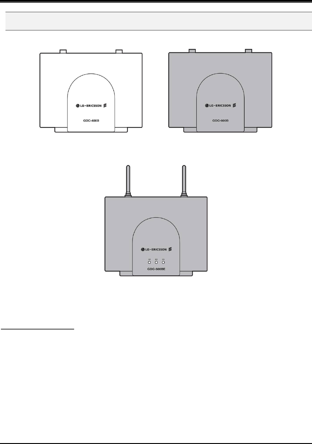
Figure 6.3.1 GDC-400B, GDC-600B(Europe Models)
Figure 6.3.2 GDC-600BE(USA/Europe Model)
There are two ways in installing the base station:
Mounting Base Station - 1
The weight of a base station is light as approx. 460g, so it can be mounted on a masonry or dry-wall surface, wooden
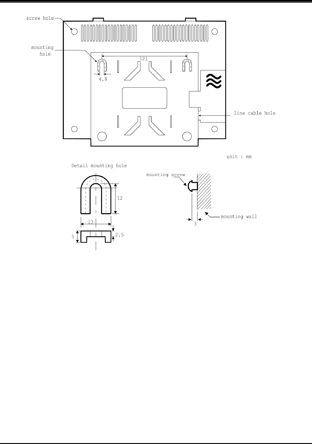
wall, or partition wall. The distance between mounting holes is 121mm as shown below. The base station is mounted
with 1 1/2 inch or longer screws. Drill pilot holes in the two locations, insert the screws and tighten leaving about 3mm
gap between the wall and screw head. Mount the base station on the screws and tighten the screws securely.
Before mounting base station permanently, you should determine locations that provide the best coverage. The wall
mounting procedure of a base station is as follows:
1. Drill two 3.5mm holes in a fixed wall. To properly position the holes, you can use mounting template that is the la
st sheet of this manual and copy it if necessary.
2. Insert anchors into the drilled holes. Then insert screws in the anchors, leaving a 3mm gap between the wall and
screw head.
3. Mount the base station eyelets on the screws.

ipLDK-60 Hardware Description and Installation Manual Issue 2
TERMINAL CONNECTION AND WIRING METHOD July, 2010
68
Figure 6.3.3 The back side of the GDC-400B/600B

ipLDK-60 Hardware Description and Installation Manual Issue 2
TERMINAL CONNECTION AND WIRING METHOD July, 2010
69
Mounting Base Station - 2 (Using Wedge)
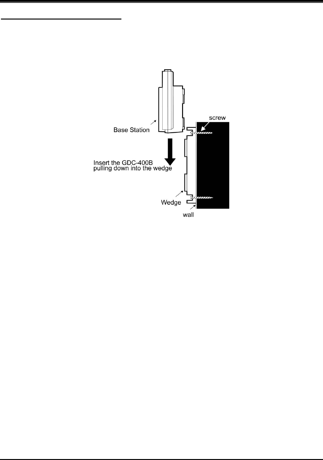
Installing the Base Station using the wedge,
1. Determine at first the location on wall where the wedge prepared for mounting the base station is to be fixed.
2. The wedge should be settled by using two screws on the wall with mounting template.
3. And insert the base station pulling down into the wedge.
Figure 6.3.4 The side of the GDC-400B/600B/GDC-600BE
Before mounting base station permanently, you should determine a suitable location providing the best coverage. Use
the last sheet of this manual for mounting template to drill pilot holes in the wall.
GDC-400B/600B/GDC-600BE Base stations may be mounted on wall or desktop up to 600m away from the WDIB4
using a twisted 2-pair unshielded cable (0.5φ, AWG 24). They are remotely powered (DC 30 volts) by the WDIB4.
The number of base stations used in a system depends on the area to be covered and the traffic density. The typical
in-house coverage is a 40m radius. In practice the cell size may vary between 10 meters indoor in worst cases
situation and up to 200m outdoor in free space.

ipLDK-60 Hardware Description and Installation Manual Issue 2
TERMINAL CONNECTION AND WIRING METHOD July, 2010
70
6.3.1 Installation of the Ferrite core and wiring
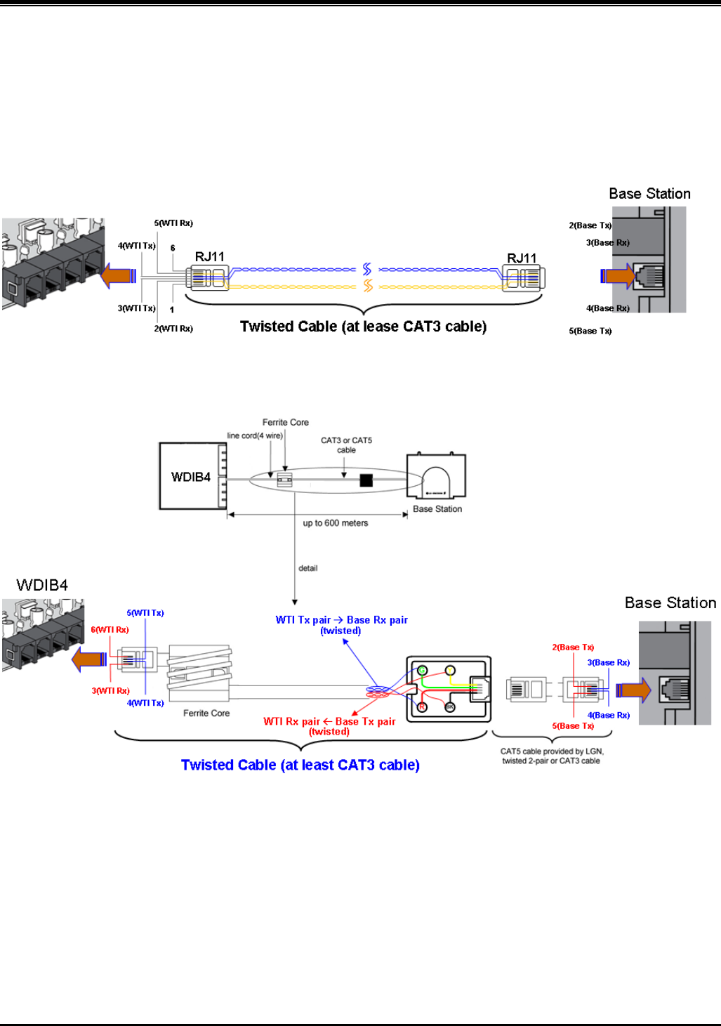
Ferrite core is provided in the package of Base station for EMI. Ferrite core should be installed when WDIB4 is
installed in the key telephone system. One Ferrite core in the package of base station is for line cord between base
station and each port of WDIB4.
Figure 6.3.5 Simple direct cable connection
Figure 6.3.5 Practical cable connection with Ferrite Core & Connetion tab