Ericsson Radio Access KRB1011047-1 Multicarrier cellular amplifier User Manual TUG
Ericsson Radio Access AB Multicarrier cellular amplifier TUG
Contents
- 1. user manuall cover page
- 2. Installation Manual
Installation Manual

MCPA 50/100 W Installation Instruction
EN/LZT 123 5396 99-08-20 1
Abstract
The installation instruction shall be used when installing the Multi Carrier Power
Amplifier MCPA 50/100W with the RBS 884.
Application
This document can be a part of the site installation of the RBS 884 library.
Contents
1 Introduction..........................................................................................2
1.1 Revision Information ............................................................................2
1.2 About this manual ................................................................................2
1.3 Document information..........................................................................3
1.3.1 Terminology.........................................................................................3
1.4 Safety Consideration............................................................................3
1.4.1 High Frequency....................................................................................3
1.4.2 ESD .....................................................................................................4
1.4.3 High Voltage ........................................................................................5
1.5 Legal Information .................................................................................5
1.6 Support ................................................................................................6
2 System Description ..............................................................................7
2.1 General................................................................................................7
2.2 RBS 884 Micro 800 MHz with MCPA ...................................................7
2.3 Definitions............................................................................................7
2.4 Installation Configurations....................................................................8
2.4.1 General................................................................................................8
2.5 Included Equipment in the mounting kit................................................9
2.6 MCPA design.....................................................................................10
2.7 Technical Specification ......................................................................11
2.8 Connectors ........................................................................................11
2.9 Indicators ...........................................................................................12
3 Installation..........................................................................................13
3.1 General..............................................................................................13
3.2 Safety Considerations........................................................................13
3.2.1 Grounding of the MCPA Cabinet........................................................13
3.2.2 Radio Frequency Radiation................................................................13
3.2.3 Tool List .............................................................................................14
3.3 Installation in an 19-Inch Equipment Cabinet .....................................15
3.3.1 Installation of MCPA...........................................................................15
3.3.2 Mounting of brackets including fan unit ..............................................16
4 Cabling of the MCPA and HPC/LPS...................................................21
5 Installation Test..................................................................................23
6 Maintenance ......................................................................................24
6.1 Replacement of HPC/LPS..................................................................24
6.2 Replacement of MCPA.......................................................................24

MCPA 50/100 W Installation Instruction
EN/LZT 123 5396 99-08-20 2
1 Introduction
This part describes the information contained in the manual and the conventions used
in its presentation.
1.1 Revision Information[J1]
This is the first issue of the manual.
1.2 About this manual
This manual contains the information required to install. troubleshoot, and maintain
the MCPA Multi Carrier Power Amplifier 50/100 W. The manual has references to
the RBS 884M Installation and Maintenance manual.
It is assumed that before the manual is used to perform any of these activities at a
Radio Base Station 884M (RBS 884M), the following actions have to be completed:
• RBS884 installation (if not, read this manual anyhow)
• DC power supply (27V) to MCPA must have been made available
The manual is divided into the following parts:
Introduction
A description of the contents of the manual and how the manual can be used.
System Description
A description of the MCPA equipment hardware and the available configurations.
Installation
Procedures for the installation, powering up and adjustment of MCPA equipment on
site.
Cabling
Procedure for the cabling of the MCPA and HPC/LPS units.
Maintenance
Procedures for basic troubleshooting and replacement of faulty items of equipment.
The target audience for the manual is RBS 884M site installation and site main-
tenance personnel.
The procedures in the manual are normally intended to be performed in the order
presented.
MCPA 50/100 W Installation Instruction
EN/LZT 123 5396 99-08-20 3
1.3 Document information
1.3.1 Terminology
Abbreviations
AC/DC Power supply
HPC High Power Combiner
DPX Duplex Filter
MCPA Multi Carrier Power Amplifier
MCU Measuring Coupler Unit
MSC Mobile Telephony Switching Center
NC Normally Closed
NO Normally Open
RF-IN RF input signal to the MCPA
RF-OUT RF output signal from the MCPA
RTP Research Triangle Park, NC, USA
TRX Transceiver Unit
TXBP TX Bandpass filter
MCU Measuring Coupler Unit
RFTL Radio Frequency Test Loop
1.4 Safety Consideration
1.4.1 High Frequency
The radio base station contain equipment that generates high frequency
electromagnetic field during operation to which the following warning applies.
WARNING
HIGH FREQUENCY ELECTROMAGNETIC FIELDS
The transmitter antenna and directly connected equipment generate high
frequency electromagnetic fields during operation. The high energy density
can cause damage to the eyes and certain tissues in the human body on persons
exposed to the radiation close to the antenna.
The station must be switched off when working with the transmitter antenna.
Avoid being close to the antenna when the station is in operation.
MCPA 50/100 W Installation Instruction
EN/LZT 123 5396 99-08-20 4
High frequency warning symbol
Following applicable warnings from the responsible telecommunication authority.
1.4.2 ESD
CAUTION
Electro Static Discharge
To avoid accidental damages while handling printed circuit boards, it is
recommended to wear a wrist strap connected to earth via a protective resistor.
Circuit boards must be kept in antistatic packing material during storage and
transportation.
ESD warning symbol
Practically all electronic components used in the RBS equipment are susceptible to
electrostatic discharges, ESD. The discharge of an electrostatic voltage exceeding 600
volt against a component will be damaging for the component, also when it is
mounted on a circuit board.
Discharges of electrostatic voltages below 4000 volt are normally not sensed or in any
other way realized by the person causing the discharge.
Normal movements by a person wearing synthetic garments, for example, can cause
the generation of electrostatic voltages of above 10.000V!.
MCPA 50/100 W Installation Instruction
EN/LZT 123 5396 99-08-20 5
The components are damaged by an electric breakdown of the ultra thin insulating
layers in the integrated circuits (typically 0,0001mm). The damage can be either acute
and lead to instant failure of functions or it can be latent and will then materialise
only after a lapse of time which may be up to several years!
1.4.3 High Voltage
The radio base station contains equipment that generates high voltages during
operation to which the following warning applies.
WARNING
HIGH VOLTAGE
All installation of power cables and units shall be performed by authorized
personnel.
Only authorized personnel with enough knowledge of the RBS system and
units are allowed to work with the different units. It is not allowed to open
incased units.
Warning Symbol for high voltage
Follow applicable warnings from the responsible authority.
1.5 Legal Information
Note:
This equipment has been tested and found to comply with the limits for a Class B
digital device, pursuant to Part 15 of the FCC Rules. These limits are designed to
provide reasonable protection against harmful interference when the equipment is
operated in a commercial environment. This equipment generates, uses, and can
radiate radio frequency energy and, if not installed and used in accordance with the
instruction manual, may cause harmful interference to radio communications.
Operation of this equipment in a residential area is likely to cause harmful interface in
which case the user will be required to correct the interference at his own expense.

MCPA 50/100 W Installation Instruction
EN/LZT 123 5396 99-08-20 6
NO MODIFICATIONS: Modifications to this device shall not be made without the
written consent of Ericsson, Incorporated. Unauthorized modifications may void the
authority granted under Federal Communications Commissions Rules permitting the
operation of this device.
In order not to violate the FCC certification of this MCPA, a filter must be used
between the MCPA output and the antenna. The filter attenuation must greater or
equal to:
Frequency range
(MHz) Attenuation
(dB)
910 – 1788 45
1788 – 2700 20
If the MCPA is used together with the RBS 884 micro and installed according to this
manual, the filter requirement is automatically fulfilled. If the MCPA is used for any
other purpose: contact Ericsson.
1.6 Support
For technical assistance, please contact your local Ericsson office.If further technical
assistance is needed, please contact:
Ericsson Radio Access AB
Antenna Near Products
P.O. Box 11
SE-164 93 Stockholm
Telephone: +46 8 757 15 00
Fax: +46 8 757 13 69
Help Desk: E-mail: anhelp@rsa.ericsson.se

MCPA 50/100 W Installation Instruction
7
2 System Description
2.1 General
This part of the manual describes the Multi Carrier Power Amplifier (MCPA)
equipment hardware and the available configurations.
2.2 RBS 884 Micro 800 MHz with MCPA
The RBS 884 Micro 800 MHz with MCPA is a standard RBS 884 Micro equipped
with a Multi Carrier Power Amplifier (MCPA) for higher output power in one cell.
The MCPA and the HPC/LPS are separate units and can be mounted below the main
cabinet.
2.3 Definitions
• Micro Base Cabinet (MBC):
One cabinet and its internal equipment, supporting one complete cell or a part of
one cell.
• Micro Base (MB):
One node in the network supporting one or more microcells. Consists of one or
more Micro Base Cabinet(s) (MBC), placed at the same physical location.
• Radio Cabinet Group (RCG):
A group of transcievers/combiners connected to the same Radio Frequency Test
Loop (RFTL).
• Alarm:
An alarm in the Mobile Service Switching Centre (MSC). Shown on an alarm
display, in the MSC.
• Fault signal:
A signal from the MCPA. Can be used to initiate a fault signal or an alarm i MSC
depending on parameter settings in the exchange.
• RBS 884M.
Name for the small, low power version of the RBS884-family.
• Cabinet:
RBS 884M 19 inch cabinet.
• Equipment Cabinet
Complete Cabinet for installation of three RBS cabinets and one MCPA unit.
MCPA 50/100 W Installation Instruction
8
2.4 Installation Configurations
2.4.1 General
The Multi Carier Power Amplifier amplifies transmitter signals within a broad band.
The MCPA 100W solution includes two MCPA units, two MCPA front panels, one
HPC/LPS unit and two cabinet fan units.
The MCPA 50W solution includes one MCPA unit, one MCPA front panel and one
cabinet fan unit.
The MCPA shall be mounted in one available position and is equipped with an alarm
signal to indicate abnormal operation of the equipment cabinet.
The MCPA output power is nominally 50W per MCPA. The 100W MCPA solution
gives 4W per carrier at 24 carriers at the MCPA output.
The MCPA is an optional product and fit to the RBS 884M program. The MCPA
shall be connected between the micro base Hybrid Combiner (HC) and the duplex
filter (DPX).
The MCPA input are connected to a signal splitter.
The input carrier level is 3dBm + 25dBm. Maximum avarage input signal is +33
dBm.
The function is amplifying RF signals from the HC and feed it to the antenna via
Measuring Coupler Unit, (MCU).
ALM
TRX1
TRX1
TRX1
TXBP MCU
RFTL
Hybrid Combiner
MCPA 50/150W
TX
R
B
S
8
8
4
N
Figur 1 MCPA environment

MCPA 50/100 W Installation Instruction
9
2.5 Included Equipment in the mounting kit.
The MCPA can be installed as single (50W) or double (100W). When single MCPA
is used no HPC/LPS unit is required.
The following equipment are included in the installation kits for 50W and 100W
respectively.
50W mounting kit NTM 20269/1
- One autenator
- One angle connector
- One front panel
- One cabinet fan unit
-Cable
- One alarm cable
100w installation kit NTM 20269/2
- Two MCPA front panels
- Two cabinet fan units
- Alarm cable kit NTM 20269/3
Mounting kit NTM 20269/3
MCPA 50/100 W Installation Instruction
10
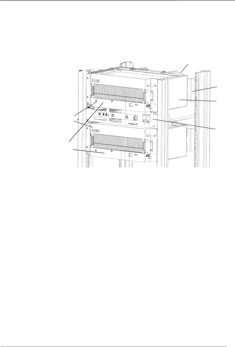
2.6 MCPA design
The MCPA is a complete stand alone unit with integrated Power Supply, cooling and
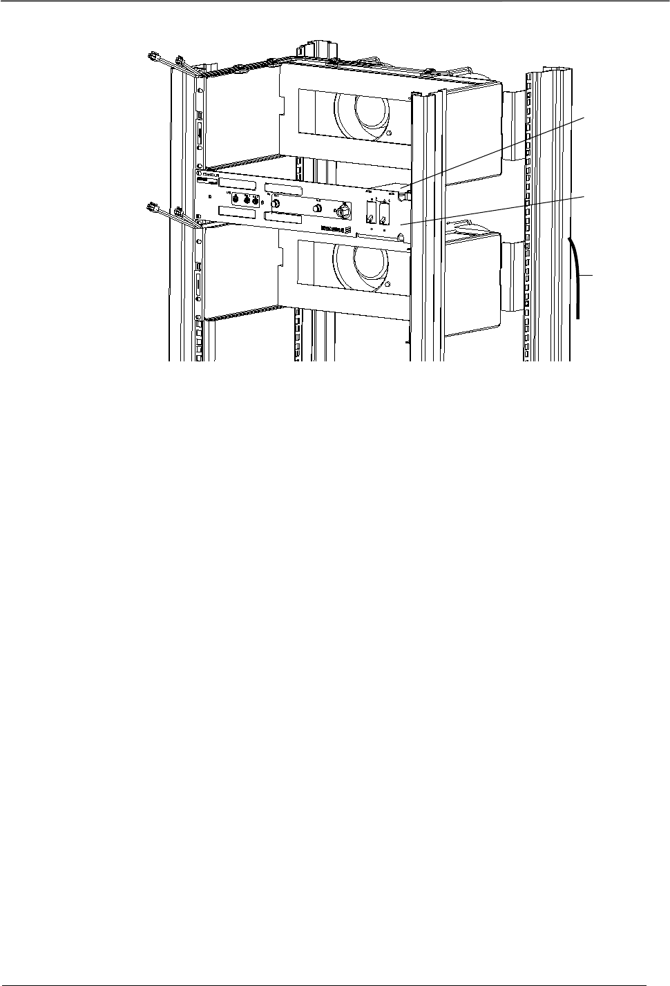
supervision. The installed MCPA 100W is shown below.
Fan unit
Support
Fan
Cabinet
HPC/LPS
MCPA
Front
panel
MCPA
Figur 2. Installed MCPA
MCPA 50/100 W Installation Instruction
11
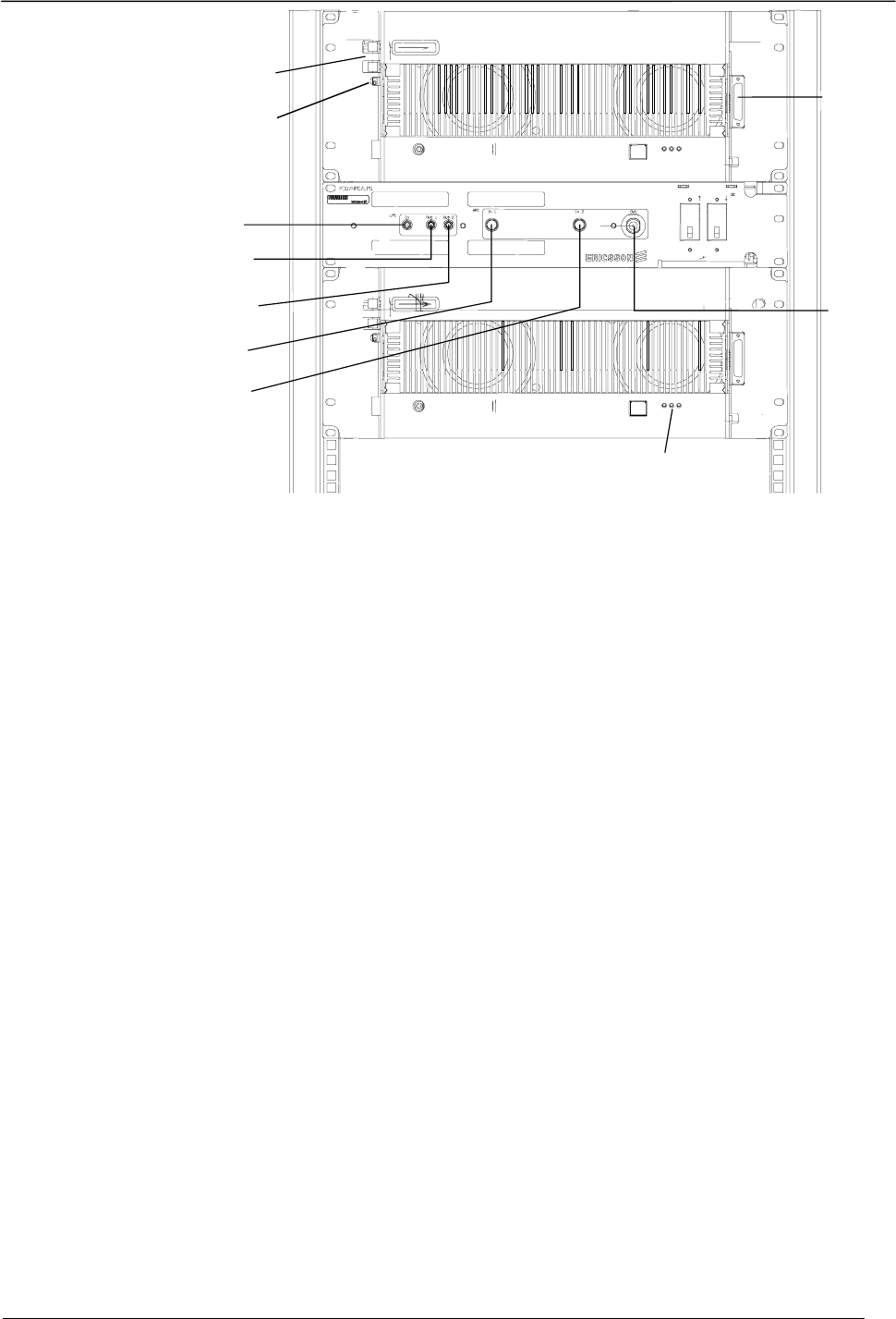
Fan
Cable
On/Off
Switch
Power
Connector
External
Output
External
Input
Output to
MCPA 1
Output to
MCPA 2
Input from
from
MCPA 1
Input from
MCPA 2
Error indication
LEDs
Figur 3 Connectors and indicators
2.7 Technical Specification
• Dimensions:
- Width: 19” rack mounting
- Depth: 14”
- Height: 11”
• Weight: 47 kg totally
• Weight one MCPA: 17 kg
• Frequency range: 869 - 894 MHz
• Power Supply DC: 27V ±1V, 1600W
• Power 50W per MCPA (100W totally)
• Output Power: 4W per carrier, 24 carriers
2.8 Connectors
RF INPUT coaxial SMA
RF OUTPUT coaxial TNC
RF TEST coaxial SMB

MCPA 50/100 W Installation Instruction
12
ALARM INTERFACE
and Control 9 Pole male D-SUB, type RPT 403 147/109
TEST & TRIM
only for authorized personell 8 Pole modular, type RNV 403 22/008
DC POWER IN 5 Pole male D-SUB, type RPT 403 140/001
FAN 1 & 2 4 Pole Molex, type RPV 403 109/04
2.9 Indicators
Status Yellow Light when start up, flashing when RF signal is on.
Error Red Flashing when start up, light steady at error.
Power Green Lit when power is on.

MCPA 50/100 W Installation Instruction
13
3 Installation
3.1 General
This part of the manual contains procedures for installation of the MCPA equipment
on site with cable installation and power up. The MCPA shall be installed at the
bottom position of the RBS 884M 19-inch equipment cabinet.
If the MCPA unit shall be installed in an equipment cabinet with RBS Cabinets
already installed, the RBS cabinet must be dismounted and before new MCPA is
mounted.
3.2 Safety Considerations
3.2.1 Grounding of the MCPA Cabinet
The MCPA-kit cabinets must be connected to the DC power mains through a special
power cable min. 16 mm2 (Red). A ground cable 16 mm2 (Blue) shall be firmly
connected to the site grounding system.
DANGER!
Any interruption of the protective (grounding) conductor, or disconnection of the
protective ground terminal will cause a potential shock hazard that could result in
personal injury.
3.2.2 Radio Frequency Radiation
DANGER!
Radio frequency radiation from an antenna may be a danger to health, causing severe
burns to skin and clothing.
Tell the MSC to switch off the transmitters if you work with or near antennas.

MCPA 50/100 W Installation Instruction
14
3.2.3 Tool List
In the following list, all the tools needs to install the MCPA, to connect the power
cable and grounding cables and to perform power up, are shown.
Table 1. Tool list
Product Number Description
LSA 126 11/30 /70 Torx Screwdriver TX30 + TX20
Posidrive no. 1, small posidrive no. 0
LTT 601 82 Torque Set with SMA tool (for the coaxial cables)
DC Voltmeter
(for checking the line voltage)
RF Power measuring equipment
Cutter
Metric Tape Measure
LYB 250 01/14 EDS Wrist Strap and Cable
14 mm block socket wrench

MCPA 50/100 W Installation Instruction
15
3.3 Installation in an 19-Inch Equipment Cabinet
This section describes the procedure for installing MCPA unit, in a 19-inch
equipment cabinet.
Two types of installations are available:
1. Installation in an already, with RBS cabinet installed, 19-inch equipment
cabinet.
2. New installation of MCPA in an empty space in a 19-inch equipment cabinet.
3.3.1 Installation of MCPA
Recommended place for the MCPA installation is the lower part in the cabinet. For
dismounting of installed equipment please refer to the RBS 884M Installation and
Maintenance Manual.
In the mounting kit NTM 20269/1/2/3 for the MCPA, all the materials needed for
mounting the MCPA in the 19-inch equipment cabinet, such as captive nuts supports,
bolts, and fun unit are included.
Caution!
Use only the designed bolts (included in the grounding and mounting kits) for
insertion in the RBS cabinets and MCPA unit. The equipment inside the cabinet unit
can be damaged if the bolt used is too long.
MCPA 50/100 W Installation Instruction
16
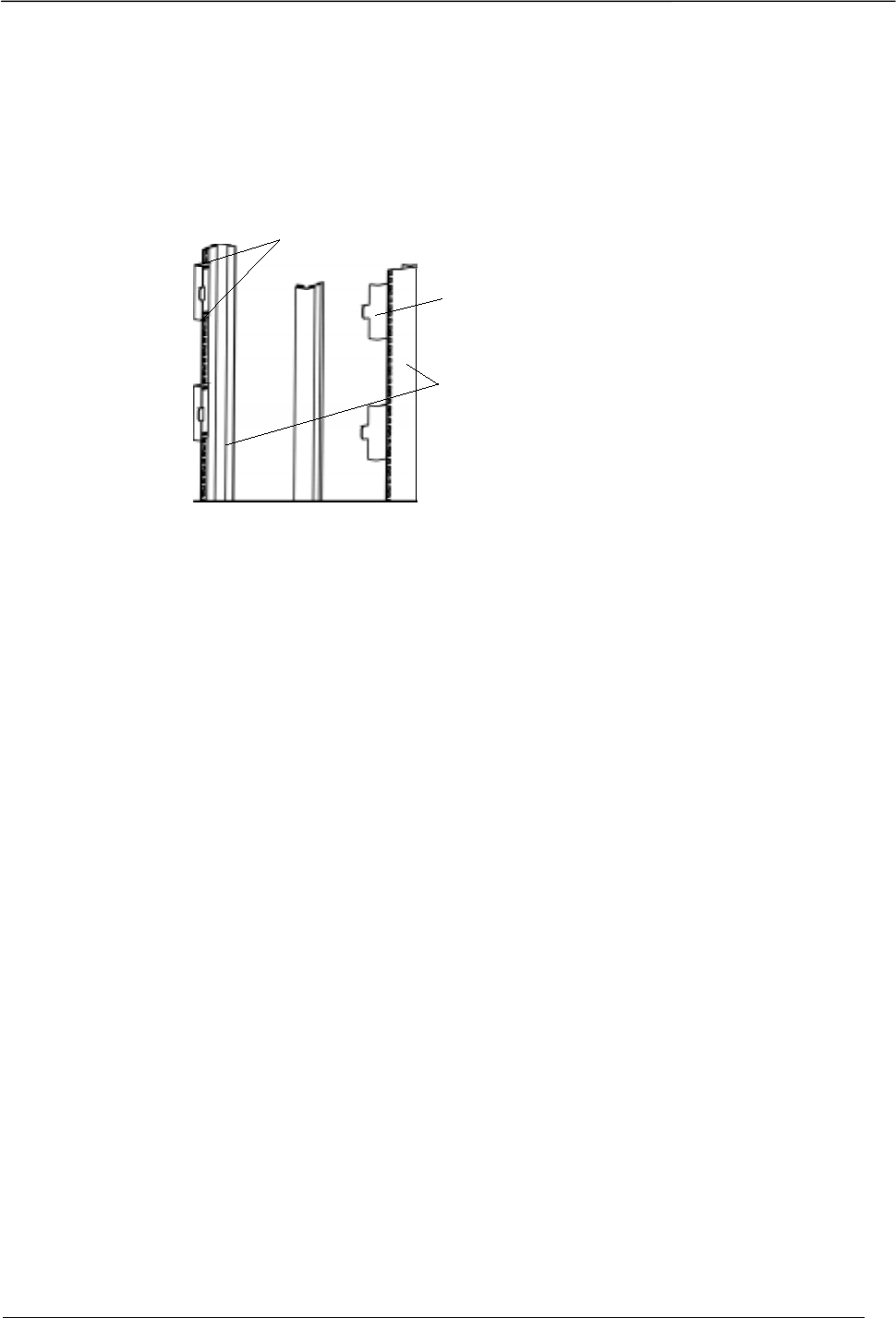
3.3.1.1 Mounting of support for fan cabinet {TC "Mounting of support for fan
cabinet"}
Two supports shall be mounted at the rear vertical bars for each fan cabinet. The
supports are used as guide pin for the fan cabinet.
C
apt
i
ve
nuts and
sc re ws
Sup p o rt
Re a r
vertical
bars
Figur 4 Mounting of supports at the rear vertical bars
3.3.2 Mounting of brackets including fan unit
For the brackets including fan unit mount captive nuts, four nuts at each side of each
bracket as described in the next steps. See the following figure.
MCPA 50/100 W Installation Instruction
17
Captive
nuts
Support
Fan
cabinet
Figur 5 Mounting captive nuts for the cabinet right side angle brackets in the 19-inch
equipment cabinet
1. Mount eight captive nuts for the upper of the fan cabinet (four of the captive nuts
are used for MCPA) in the front vertical bars.
2. Mount the upper fan cabinet. Note that the guide pin at the supports shall be put
in the two locating slots at the back of the fan cabinet.
3. Mount screws at the front, two at each side, in the uppermost and lowermost
screw-holes.
4. Mount eight captive nuts for the lower fan cabinet. Start at hole four below the
upper cabinet of the vertical bar.
5. Mount the lower fan cabinet as described above.
3.3.2.1 Installation of Mains power cables
The MCPA:s shall be feeded with +27V. Two cables with min. 16 mm2 area shall be
used, one red for +27V and one blue for ground. The maximum length of the cables
must not exceed 10 m.
Note!
If two MCPA is used (100W) two cables for +27V and ground must be installed.
The mains power cables shall be mounted with a power connector type xxxx.
1. Strip the shield of the cables about 10 mm at the connection end.
2. Mount one connector metal sheet on each cable.

MCPA 50/100 W Installation Instruction
18
3. Mount the metal sheet in the connector housing with the red cable in + and the
blue cable in -pole.
4. Connect the extra power adapter cable xxxx to the mains power connector for
MCPA1 (and 2).
5. The mains power cables shall be inserted in the cabinet from the rear and be pass
through to the front of the cabinet above HPC/LPS for MCPA1 and below
HPC/LPS for MCPA2.
6. Attach the power cables by use of cable straps at the rear of the cabinet, in
suitable position.
3.3.2.2 Mounting of HPC/LPS{TC "Mounting of PU/HPC/LPS"}
The HPC/LPS shall be mounted between the two fan cabinets.
1. Mount four captive nuts for the HPC/LPS in the front vertical bars, two nuts at
each side.
2. Before mounting the HPC/LPS, the power cables must be mounted, see section
3.3.4.2
3. Mount the cables on the HP/LPS-unit as described in section 4 before the
HPC/LPS unit is mounted in the cabinet.
4. Mount the HPC/LPS by use of four screws at the front panel.
Figure Mounting of HPC/LPS with cables. Note the cable layout.
MCPA 50/100 W Installation Instruction
19
Power
Distribution
box
PDU/HP/
LPS
Power
cable
and
ground
cable
Figur 6 HPC/LPS mounting
3.3.2.3 Mounting of MCPA front cover{TC "Mounting of MCPA front cover"}{TC
""}
The MCPA shall be mounted with a front cover which is included in the installation
kit, before they are installed in the fan cabinets.{TC ""}
1. Mount the front cover to the front of the MCPA.
2. Mount the four screws (two at each side) of the front cover.
Note.
One of the screws is used for chassie ground cable. See section 4. Cabling.
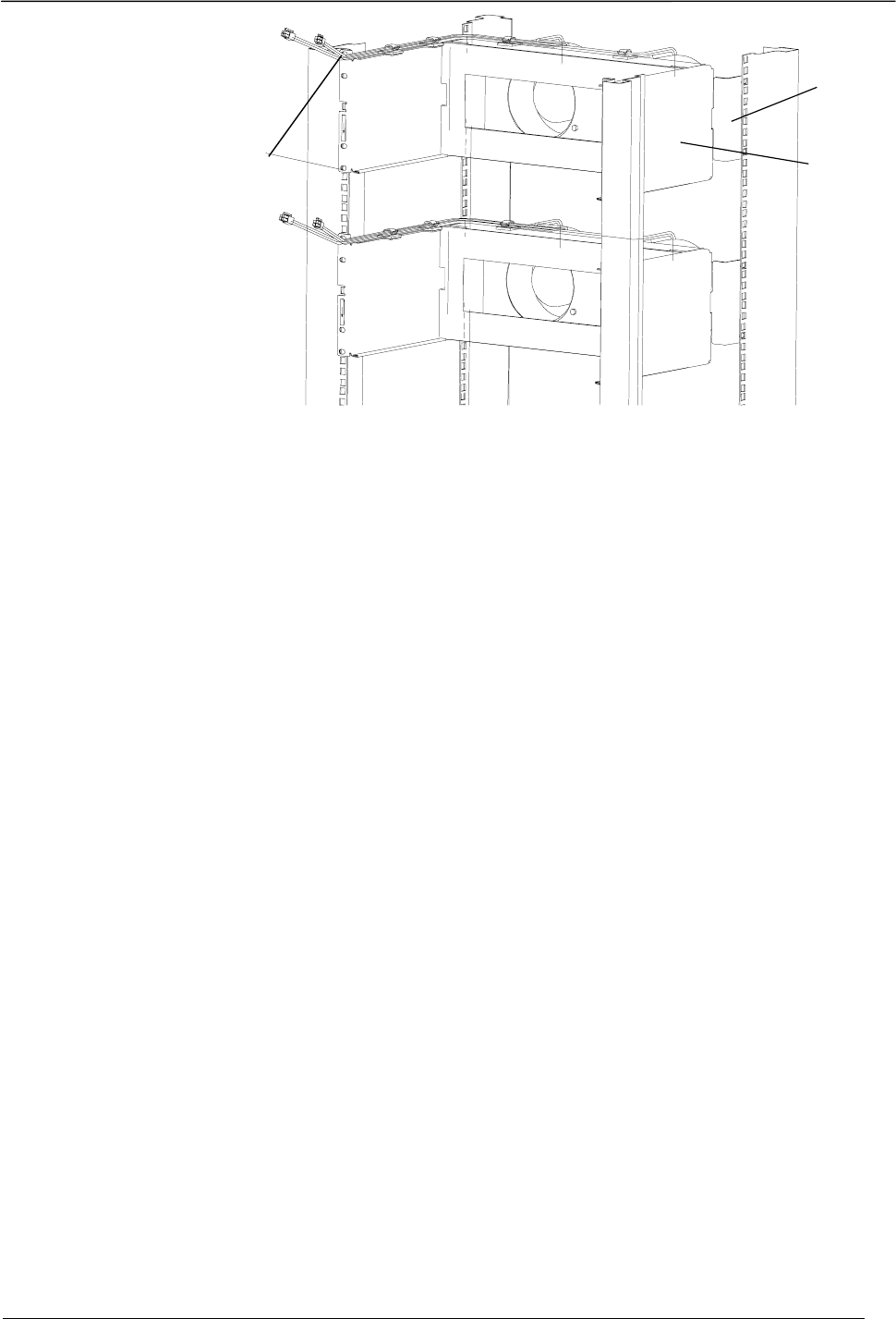
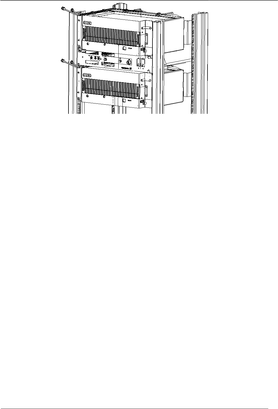
3.3.2.4 Mounting of MCPA in the fan cabinets{TC "Mounting of MCPA in the
Cabinets"}
1. Slide in the first MCPA in the upper cabinet.
2. Mount the four screws at the front of the MCPA.
3. Slide in the second MCPA in the lower cabinet.
4. Mount the four screws at the front of the MCPA.
MCPA 50/100 W Installation Instruction
20
Figur 7 Mounting of MCPA
MCPA 50/100 W Installation Instruction
21
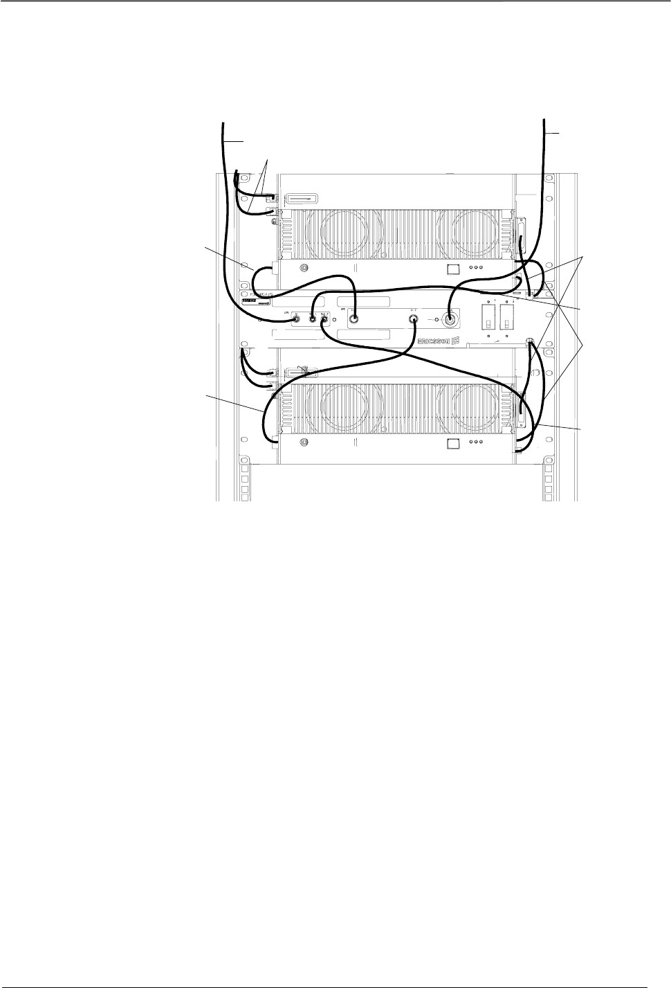
4 Cabling of the MCPA and HPC/LPS{TC
"Cabling of the MCPA and PU/HPC/LPS"}
External Input External Output
89
10
5
7
4
6
3
The numbers are referd
the list below.
11
Figur 8 MCPA HPC/LPS cabling
The MCPA and HPC/LPS shall be cabled as the description below, see
figure 12:
1. Connect the two fan cables to the MCPA 1 and 2, connector FAN 1 and FAN 2.
(3)
2. Connect the MCPA 1 RF OUT (left side) to the HPC IN 1 connector. (4)
3. Connect the MCPA 1 RF IN (right side) to the LPS OUT 1 connector. (5)
4. Connect the MCPA 2 RF OUT (left side) to the HPC IN 2 connector.(6)
5. Connect the MCPA 2 RF IN (right side) to the LPS OUT 2 connector. (7)
6. Connect the external input cable to the LPS IN connector.(8)
7. Connect the external output cable to the HPC OUT connector. (9)
8. Connect the power cables to the DC-connector on each MCPA. (10)

MCPA 50/100 W Installation Instruction
22
9. Connect the chassie ground cable to the lower screw for the MCPA front panel,
place a locking washer on the screw. (11)
10. If only one MCPA is used. The extra Alarm cable shall be fixed to the cabinet
by use of cable strap.

MCPA 50/100 W Installation Instruction
23
5 Installation Test
The installation shall be tested by power on.
WARNING
The output connector must be connected to the antenna before power on.
1. Put on the power on by pressing the push button on the left side of the MCPA.
2. Check the LED indicators see 2.9.

MCPA 50/100 W Installation Instruction
24
6 Maintenance
For ordinary maintenance and trouble shooting please refer to RBS 884M Installation
and Maintenance Manual.
6.1 Replacement of HPC/LPS
6.2 Replacement of MCPA
Sidan: 2
[J1]