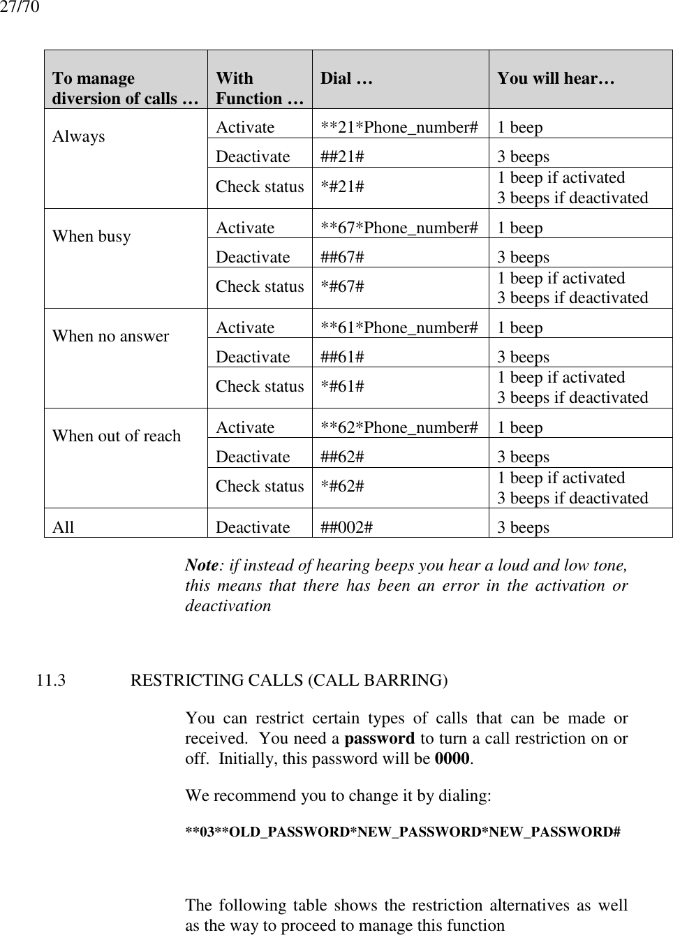
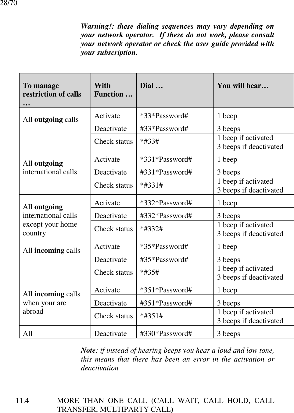
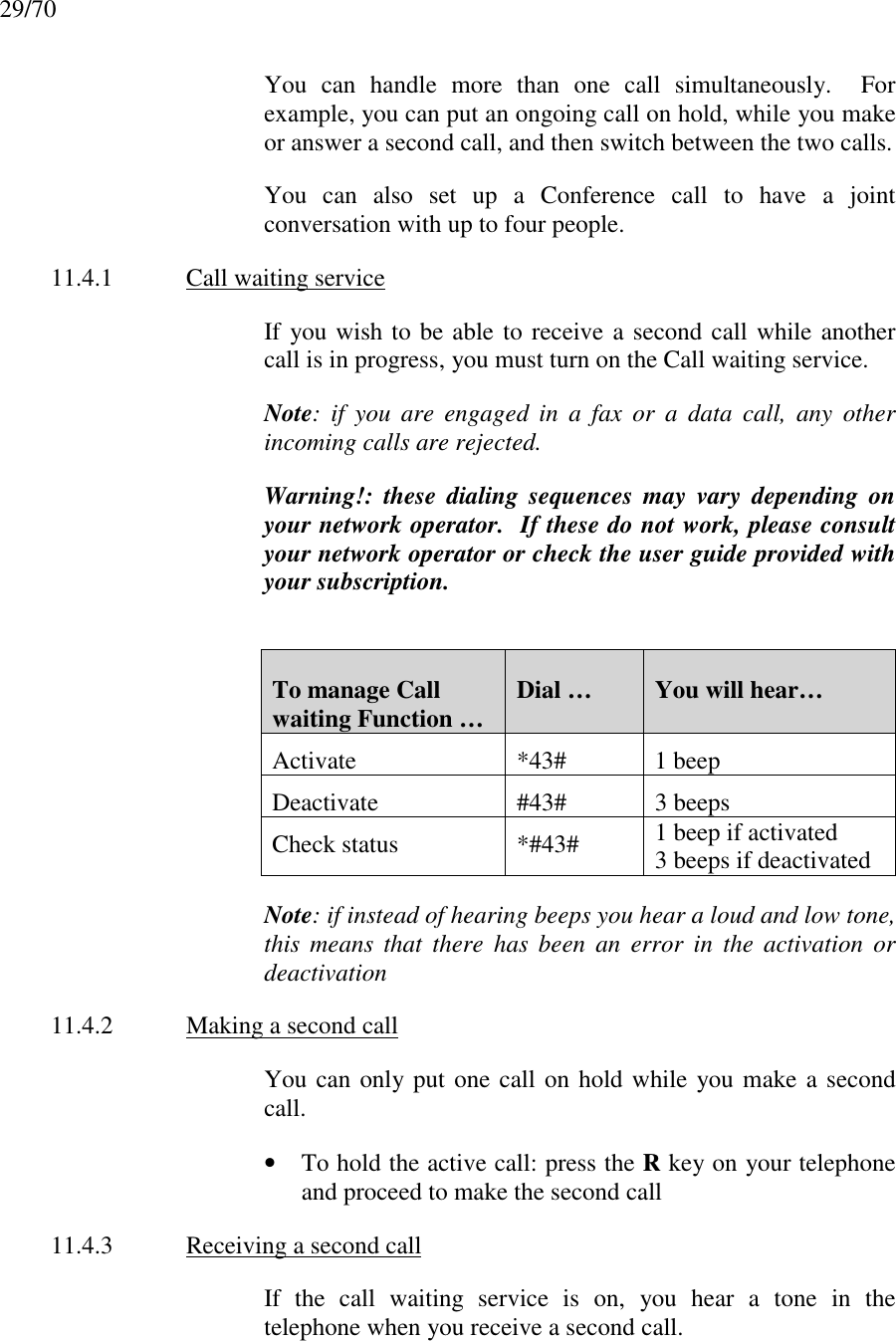
Ericsson 0130101-BV Fixed Cellular Terminal User Manual INTRODUCTION
Ericsson AB Fixed Cellular Terminal INTRODUCTION
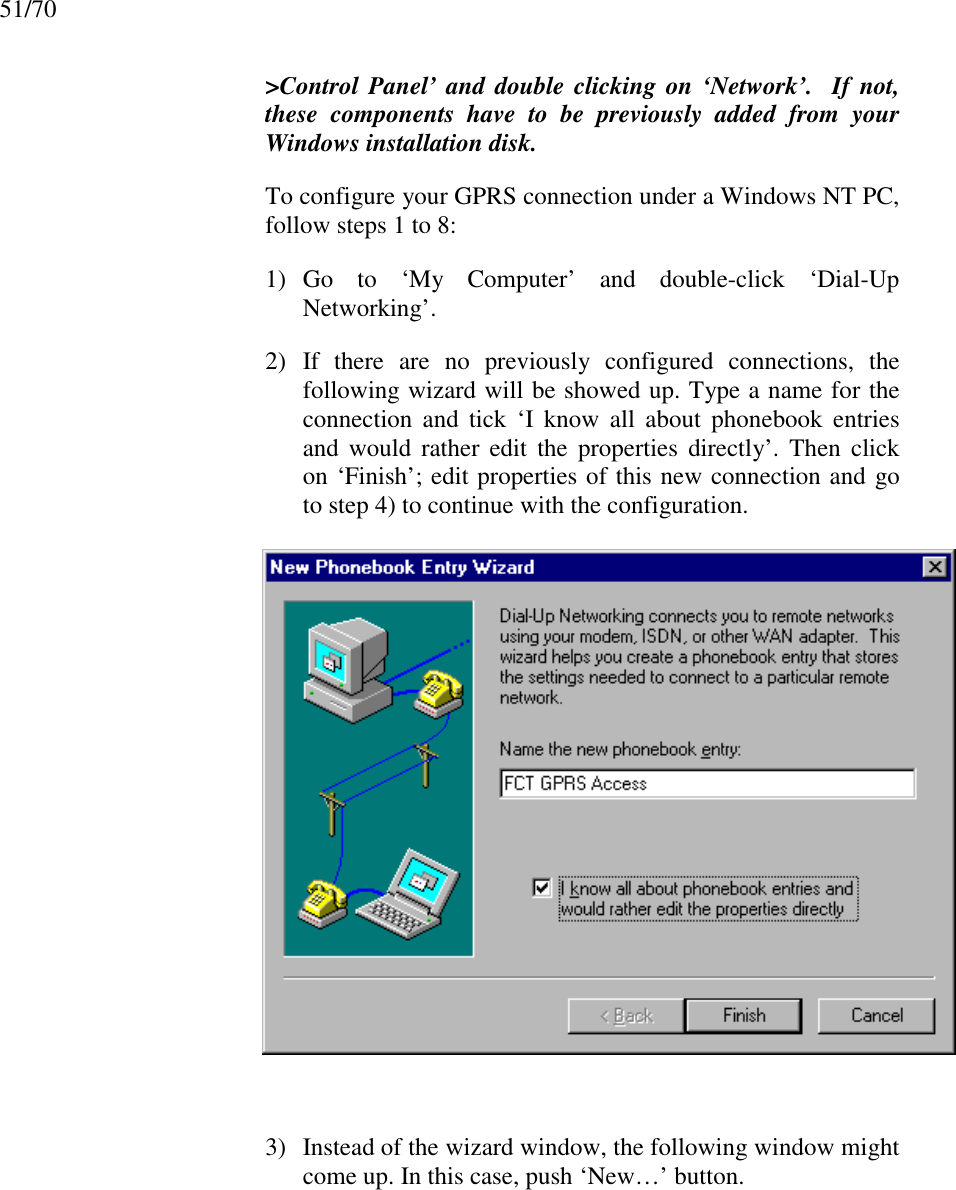
UserManual.wiki
>
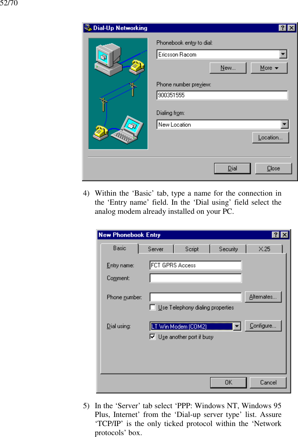
Ericsson
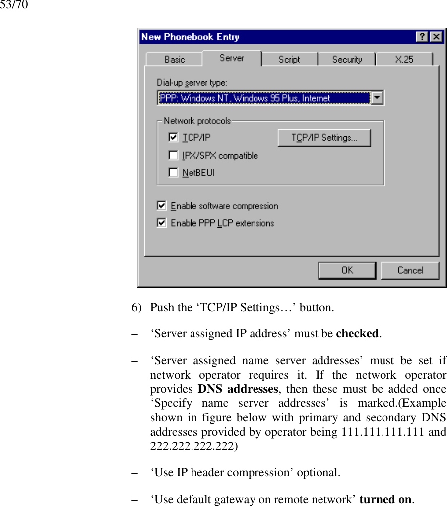
>
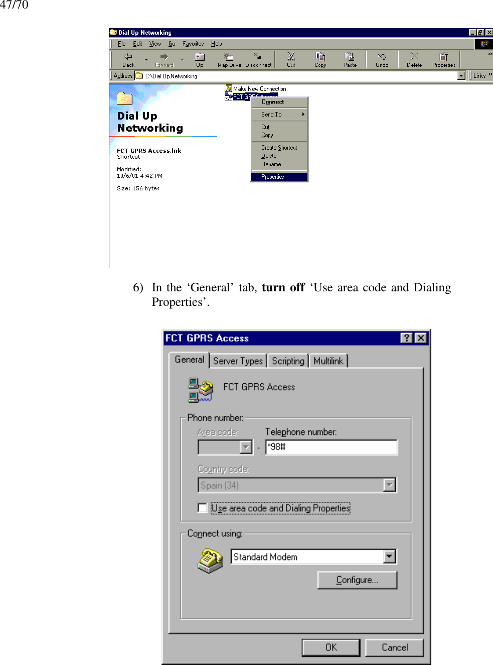
0130101 BV User Manual
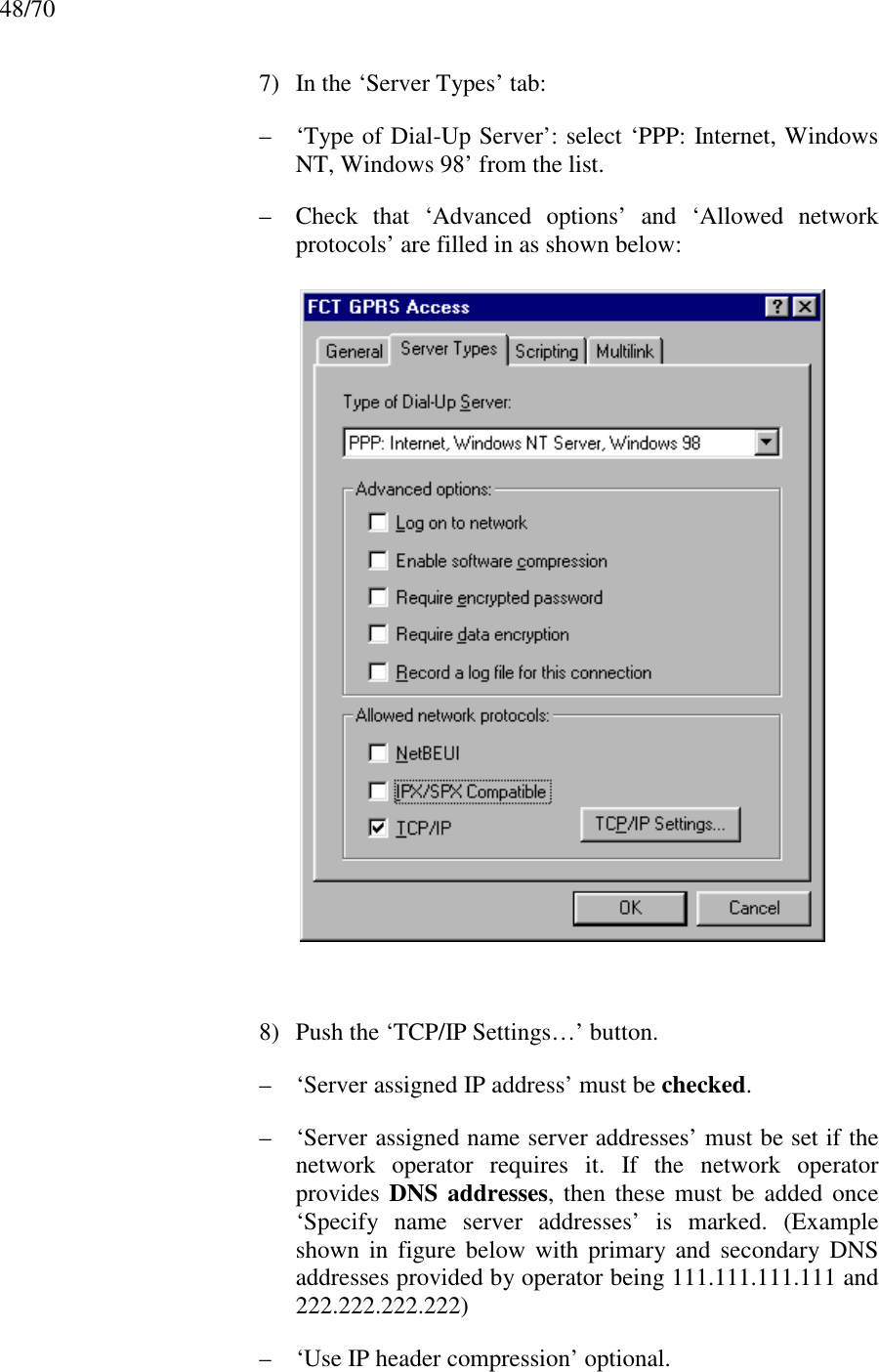
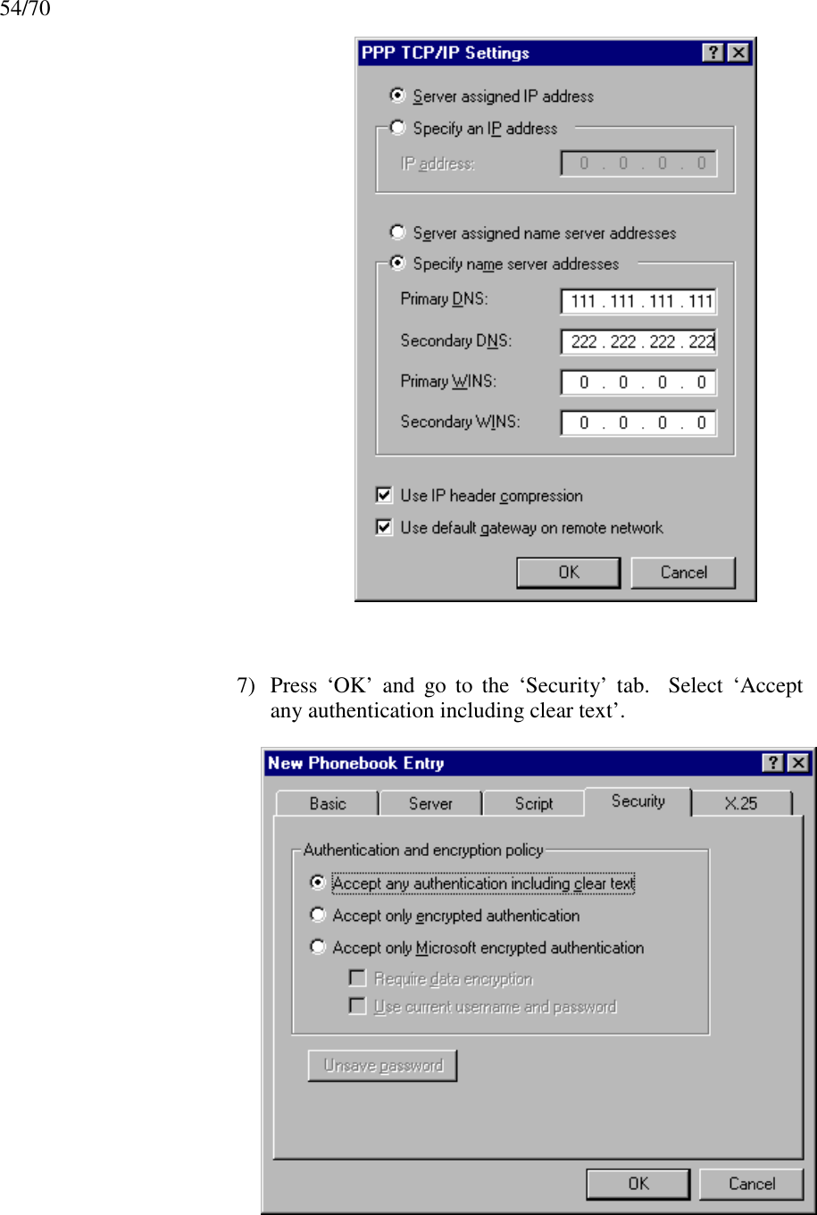
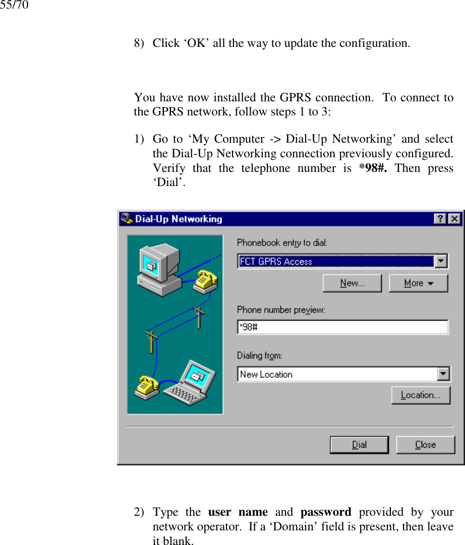
Exhibit 8 User Manual
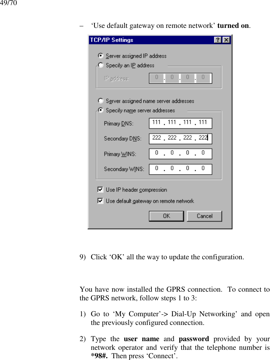
Navigation menu
Upload a User Manual
Namespaces
Wiki Guide
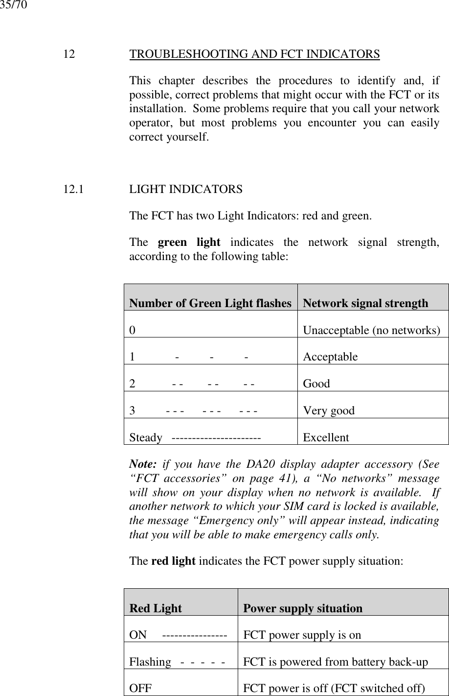
HTML
PDF
Info
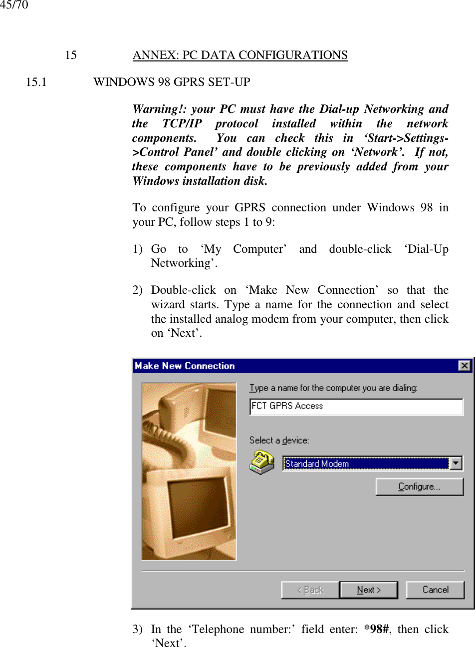
Views
User Manual
Discussion / Help
Navigation