FISHERPAYKEL Residential Dryer Manual L0812252
DE60FA27AW2-96983 DE60FA27AW2-96983 FISHER & PAYKEL RESIDENTIAL DRYER - Manuals and Guides L0812252 View the owners manual for your FISHER & PAYKEL RESIDENTIAL DRYER #DE60FA27AW296983. Home:FISHER & PAYKEL:/ Dryer Parts:FISHER & PAYKEL dryer parts:#DE60FA27AW296983 FISHER & PAYKEL dryer parts:#DE60FA27AW296983 FISHER & PAYKEL residential dryer manual
User Manual: FISHERPAYKEL FISHERPAYKEL Residential Dryer Manual FISHERPAYKEL Residential Dryer Owner's Manual, FISHERPAYKEL Residential Dryer installation guides
Open the PDF directly: View PDF ![]() .
.
Page Count: 5
WARNING- POTENTIAL FIRE AND SHOCK HAZARD
•Use only rigid metal or flexible metal 4" diameter ductwork for exhausting to the outdoors. Never use
plastic or other combustible ductwork.
• This appliance must be properly grounded and installed as described in these instructions.
•Do not install or store appliance in an area where it will be exposed to water/weather.
•The National Fuel Gas Code restricts installations of gas appliances in garages. They must be 18" off
the ground and protected by a barrier from vehicles.
Important
•Exhausting the dryer to the outdoors is strongly
recommended to prevent large amounts of moisture
and lint from being blown into the room.
• Service information and wiring diagram located
in control console.
Tools you will need
Slip joint pliers
Screwdrivers
3/8" nut driver
Installation
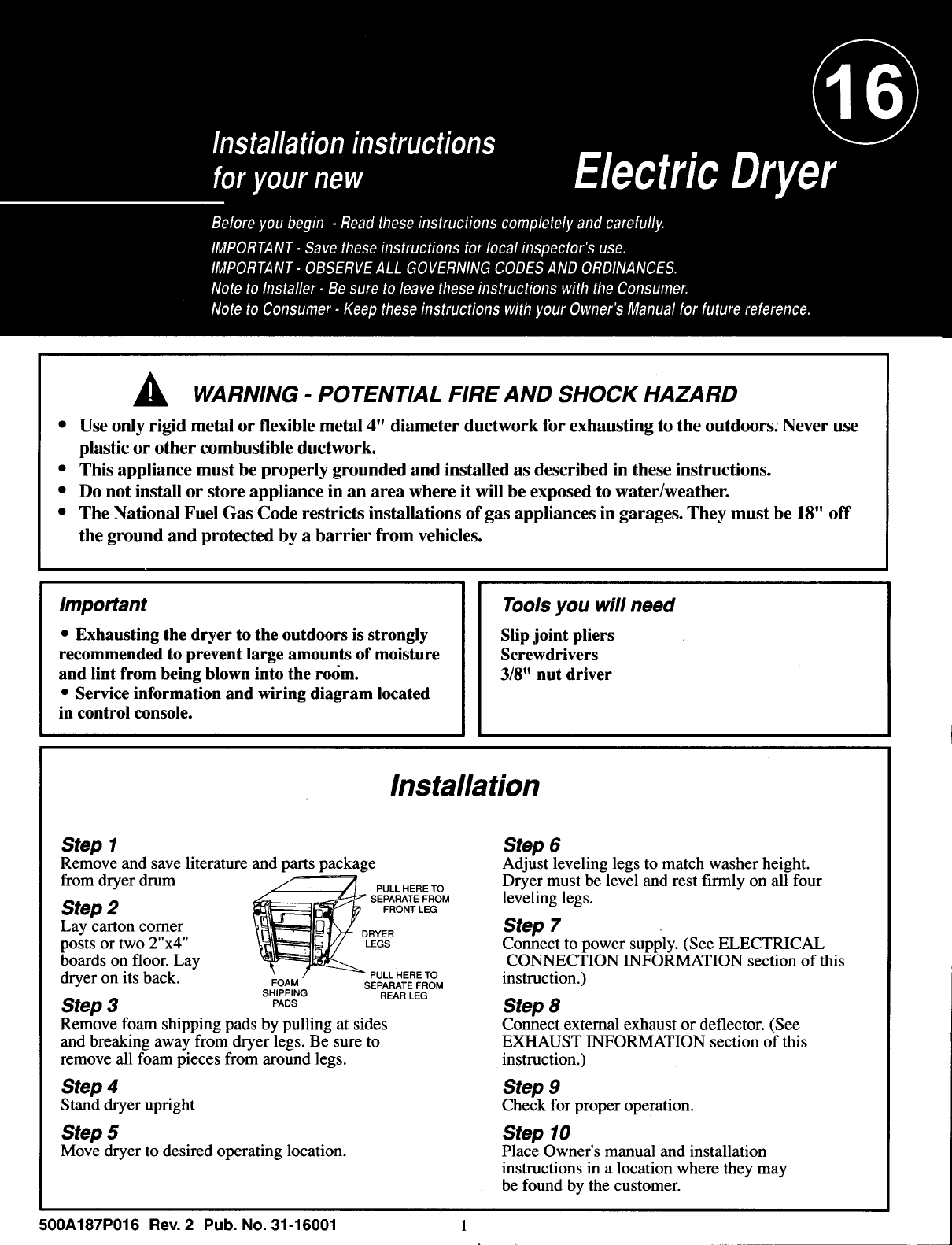
Step 1
Remove and save literature and parts package
from dryer drum PULLHEREro
Step 2 FRONTLEG
Lay carton comer DRYER
posts or two 2"x4" LEGS
boards on floor. Lay PULL HERE TO
dryer on its back. FOAM SEPARATEFROM
SHIPPING REAR LEG
Step 3 PADS
Remove foam shipping pads by pulling at sides
and breaking away from dryer legs. Be sure to
remove all foam pieces from around legs.
Step 6
Adjust leveling legs to match washer height.
Step 4
Stand dryer upright
Step 5
Move dryer to desired operating location.
Dryer must be level and rest firmly on all four
leveling legs.
Step 7
Connect to power supply. (See ELECTRICAL
CONNECTION INFORMATION section of this
instruction.)
Step 8
Place Owner's manual and installation
instructions in alocation where they may
be found by the customer.
500A187P016 Rev. 2 Pub. No. 31-16001 1
Step 10
Step 9
Check for proper operation.
Connect external exhaust or deflector. (See
EXHAUST INFORMATION section of this
instruction.)
Electrical Connection Information
WARNING: TO REDUCE THE RISK Electrical requirements:
OF FIRE, ELECTRIC SHOCK, OR
PERSONAL INJURY.
•DO NOT USE AN EXTENSION CORD
WITH THIS APPLIANCE.
•THIS APPLIANCE MUST BE PROPERLY
GROUNDED.
Dryer must be electrically grounded in
accordance with local codes and ordinances,
or in the absence of local codes, in accor-
dance with the NATIONAL ELECTRICAL
CODE, ANSI/NFPA NO. 70.
• This dryer must be connected to an
individual branch circuit, protected by the
required time-delay fuses or circuit
breakers. 208V or 240V installation 30 amps.
• If the electric supply does not meet the
above specifications, call a licensed electrician.
Grounding instructions
• This appliance must be connected to a grounded
metal, permanent wiring system, or an equipment-
grounding conductor must be run with the circuit
conductors and connected to the equipment-
grounding terminal or lead on the appliance.
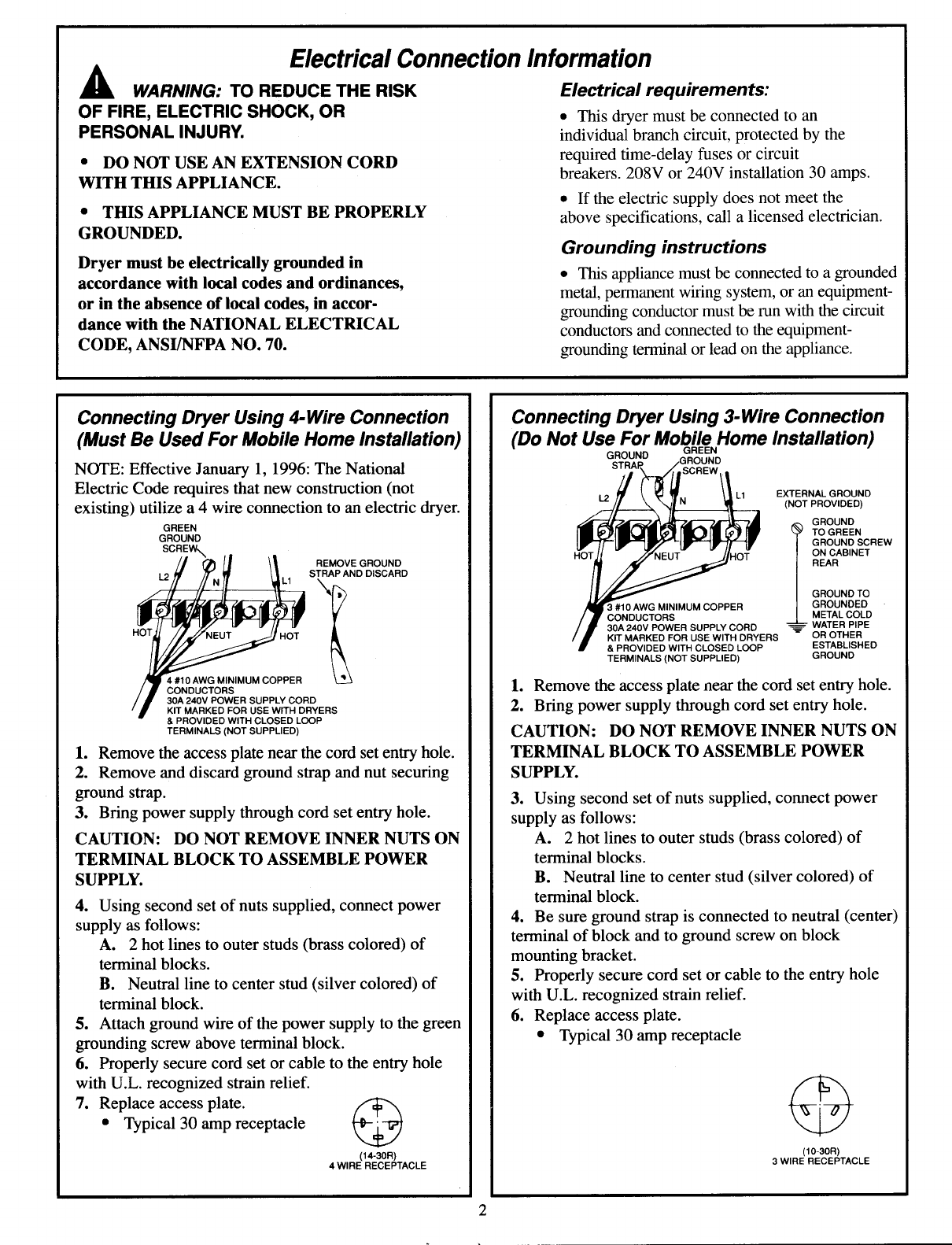
Connecting Dryer Using 4-Wire Connection
(Must Be Used For Mobile Home Installation)
NOTE: Effective January 1, 1996: The National
Electric Code requires that new construction (not
existing) utilize a 4 wire connection to an electric dryer.
GREEN
GROUND
SCREW,,.
__1 /I \l REMOVE GROUND
L.2 _'/ 7'/" IPl \| STRAP AND DISCARD
4 #10 AWG MINIMUM COPPER L_J
/JCONDUCTORS _ _
/J30A 240V POWER SUPPLY CORD
'B' KIT MARKED FOR USE WITH DRYERS
& PROVIDED WITH CLOSED LOOP
TERMINALS (NOT SUPPLIED)
1. Remove the access plate near the cord set entry hole.
2. Remove and discard ground strap and nut securing
ground strap.
3. Bring power supply through cord set entry hole.
CAUTION: DO NOT REMOVE INNER NUTS ON
TERMINAL BLOCK TO ASSEMBLE POWER
SUPPLY.
4. Using second set of nuts supplied, connect power
supply as follows:
A. 2 hot lines to outer studs (brass colored) of
terminal blocks.
B. Neutral line to center stud (silver colored) of
terminal block.
5. Attach ground wire of the power supply to the green
grounding screw above terminal block.
6. Properly secure cord set or cable to the entry hole
with U.L. recognized strain relief.
7. Replace access plate.
• Typical 30 amp receptacle %y
(14-30R)
4 WIRE RECEPTACLE
Connecting Dryer Using 3-Wire Connection
(Do Not Use For Mobile Home Installation)
GROUND GREEN
_N GROUND
SCREW --
/_L1 EXTERNAL GROUND
(NOT PROVIDED)
_GROUND
III _)11_111 @] [Uil _7 IIF ? TOGREEN
Ip_'/'-[l_'ll_'_ll_'_l_//_lV | GROUND SCREW
I-TOTJ_ -/7"_'NEUT- vJIHoT !ONCABINET
Ii/_-,_'_ / GROUNDTO
AI_I_#10 AWG MINIMUM COPPER |GROUNDED
/ # CONDUCTORS...... _L I kC°P g
/ll' 30A 240V POWER SUPPLY CORD _ R THER
/_l' KIT MARKED FOR USE WITH DRYERS O O
f &PROVIDED WITH CLOSED LOOP ESTABLISHED
TERMINALS (NOT SUPPLIED) GROUND
1. Remove the access plate near the cord set entry hole.
2. Bring power supply through cord set entry hole.
CAUTION: DO NOT REMOVE INNER NUTS ON
TERMINAL BLOCK TO ASSEMBLE POWER
SUPPLY.
3. Using second set of nuts supplied, connect power
supply as follows:
A. 2 hot lines to outer studs (brass colored) of
terminal blocks.
B. Neutral line to center stud (silver colored) of
terminal block.
4. Be sure ground strap is connected to neutral (center)
terminal of block and to ground screw on block
mounting bracket.
5. Properly secure cord set or cable to the entry hole
with U.L. recognized strain relief.
6. Replace access plate.
• Typical 30 amp receptacle
(10-30R)
3 WIRE RECEPTACLE
Exhaust information
_WARNING: TO REDUCE THE RISK
OF FIRE AND PERSONAL INJURY:
•Use only metal duct for exhausting dryer to
outdoor.
•Do not terminate exhaust in a chimney, any gas
vent, under an enclosed floor (crawi space), or into
an attic. The accumulated lint could create a fire
hazard.
•Provide an access for inspection and cleaning of
the exhaust system, especially at turns. Inspect and
clean at least once per year.
•Never terminate the exhaust into a common duct
with a kitchen exhaust. A combination of lint and
grease could create a fire hazard.
•Do not obstruct incoming or exhausted air.
Rear Exhaust Location
This dryer comes ready for rear exhausting.
U JJ 31/2
i "
nnl....... .OTE:A ,ever.ca, ,n,ens,on
L___ _.J_ J_ theOistancebetweencaOJne,
i;_ [--- - I _ bottom to floor surface.
11 3/4"
Steps to change Dryer to Side or Bottom
Exhaust
1. Remove Access Panel. -- _
2. Straighten up the tab inside the exhaust duct at
the back of the appliance, then remove the internal
duct connected to
the blower housing.
3. Cut the duct as shown, iiiiii_----_ '_
TAB OPENING /F8 5/8" _'l
4. Reconnect and secure the cut portion of the duct
to the blower housing. Make sure that the tab portion
is at the bottom of the duct.
r"
BLOWER / r t
HOUSING ---_ L_
8 5/8" CUT l "I
PORTION ---_1 I
TAB
OPENING l_j
'
4 3/4"
I
Il'Only metal duct
may be used
inside the dryer
cabinet
i _°_a
=-t 4 3/4"
NOTE: To secure the duct, insert the tab (located on
the appliance base) in the opening and bend it.
5. Detach and remove the desired knockout.
6. Use standard metal elbow and duct to exhaust.
7. Cover the opening at the back with the plate pro-
vided on the back of the appliance.
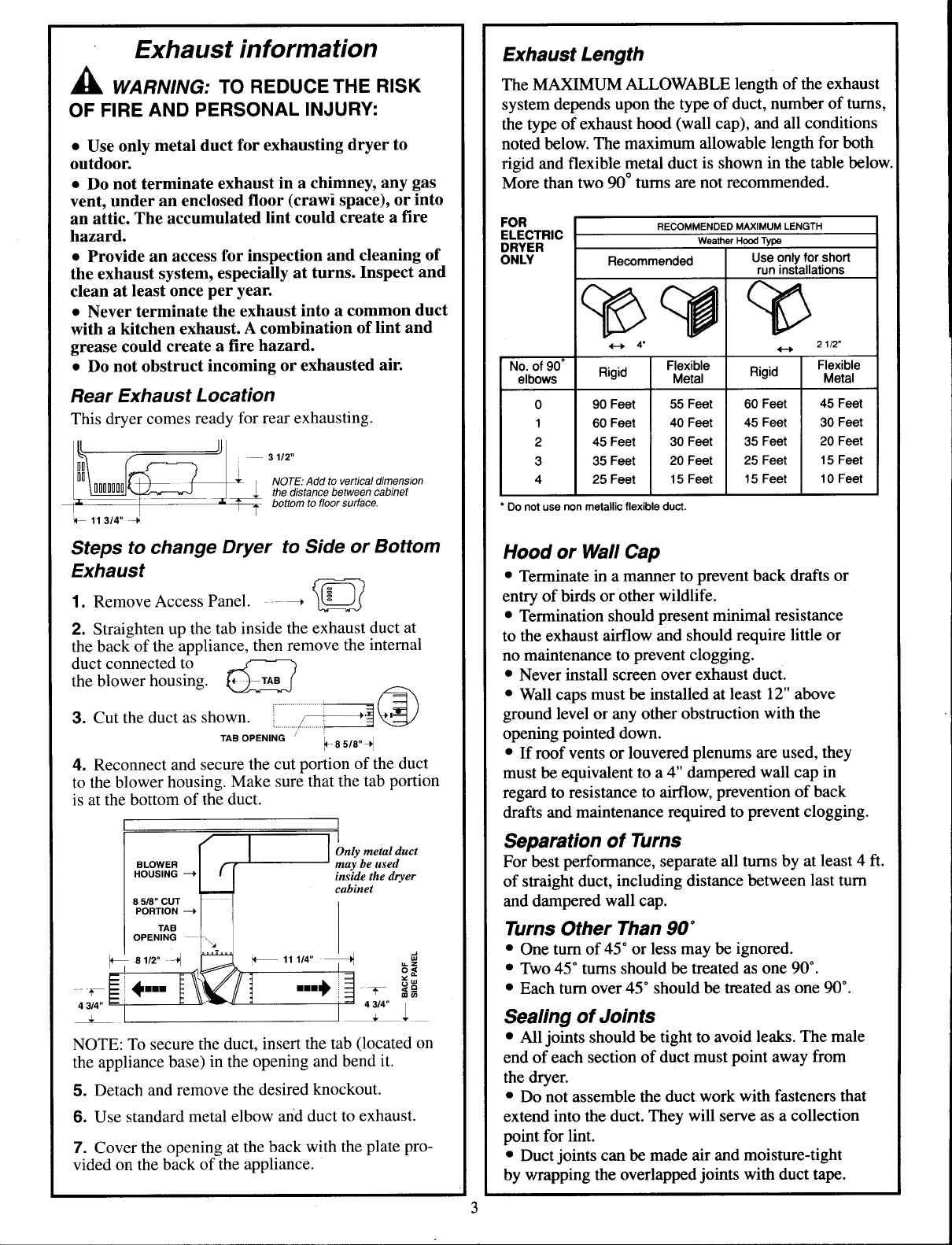
ExhaustLength
The MAXIMUM ALLOWABLE length of the exhaust
system depends upon the type of duct, number of turns,
the type of exhaust hood (wall cap), and all conditions
noted below. The maximum allowable length for both
rigid and flexible metal duct is shown in the table below.
More than two 90 °turns are not recommended.
FOR RECOMMENDED MAXIMUM LENGTH
ELECTRIC
DRYER Weather Hood Type
ONLY Recommended Use only for short
run installations
4"
Rigid Rigid
No. of 90 °
elbows
0
1
2
3
4
90 Feet
60 Feet
45 Feet
35 Feet
25 Feet
Flexible
Metal
55 Feet
40 Feet
30 Feet
20 Feet
15 Feet
60 Feet
45 Feet
35 Feet
25 Feet
15 Feet
2 112"
Flexible
Metal
45 Feet
30 Feet
20 Feet
15 Feet
10 Feet
Do not use non metallic flexible duct.
Hood or Wall Cap
• Terminate in a manner to prevent back drafts or
entry of birds or other wildlife.
• Termination should present minimal resistance
to the exhaust airflow and should require little or
no maintenance to prevent clogging.
• Never install screen over exhaust duct.
• Wall caps must be installed at least 12" above
ground level or any other obstruction with the
opening pointed down.
• If roof vents or louvered plenums are used, they
must be equivalent to a 4" dampered wall cap in
regard to resistance to airflow, prevention of back
drafts and maintenance required to prevent clogging.
Separation of Turns
For best performance, separate all turns by at least 4 ft.
of straight duct, including distance between last turn
and dampered wall cap.
Turns Other Than 90*
• One turn of 45° or less may be ignored.
• Two 45 ° turns should be treated as one 90 °.
• Each turn over 45 ° should be treated as one 90 °.
Sealing of Joints
• All joints should be tight to avoid leaks. The male
end of each section of duct must point away from
the dryer.
• Do not assemble the duct work with fasteners that
extend into the duct. They will serve as a collection
point for lint.
• Duct joints can be made air and moisture-tight
by wrapping the overlapped joints with duct tape.
Exhaust Information (cont.)
Insulation
•Ductwork which runs through an unheated area or is
near an air conditioning duct should be insulated to
reduce condensation and lint build up.
Parts Available from Local Service Organization
•Rigid Metal Duct Components
4" X 1' Duct
4" X 2' Duct
4" Elbow
4" Aluminum Hood
Exhaust Deflector
• Flexible Metal Duct Components
Kit WX8X66 7' Aluminum duct, 4" hood and
2 clamps.
7' Aluminum Flexible Duct
4" Clamps (2)
4" Aluminum Hood
UL-Listed clothes dryer transition duct.
Inside Exhausting
NOTE: MOBILE HOME, BEDROOM,
BATHROOM, ALCOVE OR CLOSET
INSTALLATIONS MUST BE EXHAUSTED
TO THE OUTDOORS.
OTHER INSTALLATION: If the installation makes it
impossible to exhaust to the outdoors, a 4" exhaust
deflector (WE25X28) must be installed. A clearance
of 8" is required between rear of dryer and the wall,
and deflector should be pointing up.
NOTE: EXHAUSTING TO THE OUTDOORS IS
STRONGLY RECOMMENDED. EXHAUSTING
INDOORS MAY CAUSE LINT ACCUMULATION,
AND MOISTURE DAMAGE INCLUDING MOLD
AND MILDEW.
Special Installation Requirements
Alcove or Closet Installation
• If your dryer is approved for installation in an
alcove or closet it will be stated on alabel on the
dryer back.
• The dryer must be exhausted to the outdoors.
• Minimum clearances between dryer cabinet and
adjacent walls or other combustible surfaces are:
0" clearance either side
3" front and rear
• Minimum vertical space from floor to overhead
cabinets, ceilings, etc. is 52".
• Closet doors must be louvered or otherwise
ventilated and must contain at least 60 square
inches open area equally distributed. If this closet
contains both a washer and a dryer, doors must contain
120 square inches of open space equally distributed.
Mobile or Manufactured Home Installation
• Installation must conform to Manufactured Home
Construction and Safety Standard, Title 24 CFR,
Part 32-80.
• The dryer must be exhausted to the outdoors with the
termination securely fastened to the mobile home
structure. (See EXHAUST INFORMATION section).
• The exhaust MUST NOT be terminated beneath the
mobile home.
• The exhaust material MUST BE METAL.
• For Electrical Connections see "CONNECTING
DRYER USING 4-WIRE CONNECTIONS".
SERVICING:
_CAUTION:
Consideration must be given to provide adequate clearances for
installation and servicing.
Label all wires prior to disconnection when servicing controls.
Wiring errors can cause improper and dangerous operation
(verify proper operation after servicing/installation).
Additional Installation Instructions
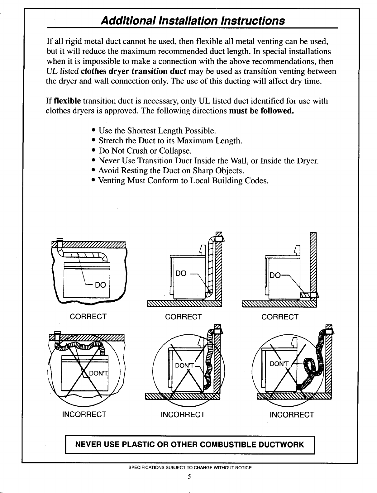
If all rigid metal duct cannot be used, then flexible all metal venting can be used,
but it will reduce the maximum recommended duct length. In special installations
when it is impossible to make a connection with the above recommendations, then
UL listed clothes dryer transition duct may be used as transition venting between
the dryer and wall connection only. The use of this ducting will affect dry time.
If flexible transition duct is necessary, only UL listed duct identified for use with
clothes dryers is approved. The following directions must be followed.
•Use the Shortest Length Possible.
• Stretch the Duct to its Maximum Length.
• Do Not Crush or Collapse.
• Never Use Transition Duct Inside the Wall, or Inside the Dryer.
• Avoid Resting the Duct on Sharp Objects.
• Venting Must Conform to Local Building Codes.
CORRECT
INCORRECT
CORRECT CORRECT
INCORRECT INCORRECT
INEVER USE PLASTIC OR OTHER COMBUSTIBLE DUCTWORK
SPECIFICATIONS SUBJECT TO CHANGE WITHOUT NOTICE
5
I
